

Motorola V200, V220, V290 Service Manual
Level 1 and 2 Service Manual
V220
Digital Wireless Telephone

1 and 2
Contents
Level 1 and 2 Service Manual Contents
V220
6809480A39-O
Introduction . . . . . . . . . . . . . . . . . . . . . . . . . . . . . . . . . . . . . . . . . . . . . . . . . . . . . . . . . . . . . . . . . . . . . . . . . . . . . . . . . 5
Product Identification . . . . . . . . . . . . . . . . . . . . . . . . . . . . . . . . . . . . . . . . . . . . . . . . . . . . . . . . . . . . . . . . . . . 5
Product Names . . . . . . . . . . . . . . . . . . . . . . . . . . . . . . . . . . . . . . . . . . . . . . . . . . . . . . . . . . . . . . . . . . . . . . . . 5
Product Changes . . . . . . . . . . . . . . . . . . . . . . . . . . . . . . . . . . . . . . . . . . . . . . . . . . . . . . . . . . . . . . . . . . . . . . . 5
Regulatory Agency Compliance . . . . . . . . . . . . . . . . . . . . . . . . . . . . . . . . . . . . . . . . . . . . . . . . . . . . . . . . . . . 5
Computer Program Copyrights . . . . . . . . . . . . . . . . . . . . . . . . . . . . . . . . . . . . . . . . . . . . . . . . . . . . . . . . . . . 6
About This Service Manual . . . . . . . . . . . . . . . . . . . . . . . . . . . . . . . . . . . . . . . . . . . . . . . . . . . . . . . . . . . . . . 6
Warranty Service Policy . . . . . . . . . . . . . . . . . . . . . . . . . . . . . . . . . . . . . . . . . . . . . . . . . . . . . . . . . . . . . . . . . 7
Parts Replacement . . . . . . . . . . . . . . . . . . . . . . . . . . . . . . . . . . . . . . . . . . . . . . . . . . . . . . . . . . . . . . . . . . . . . 8
Specifications . . . . . . . . . . . . . . . . . . . . . . . . . . . . . . . . . . . . . . . . . . . . . . . . . . . . . . . . . . . . . . . . . . . . . . . . . . . . . . 9
Product Overview . . . . . . . . . . . . . . . . . . . . . . . . . . . . . . . . . . . . . . . . . . . . . . . . . . . . . . . . . . . . . . . . . . . . . . . . . . . 11
Features . . . . . . . . . . . . . . . . . . . . . . . . . . . . . . . . . . . . . . . . . . . . . . . . . . . . . . . . . . . . . . . . . . . . . . . . . . . . . 11
General Operation . . . . . . . . . . . . . . . . . . . . . . . . . . . . . . . . . . . . . . . . . . . . . . . . . . . . . . . . . . . . . . . . . . . . . . . . . . . 14
Controls, Indicators, and Input / Output (I/O) Connections . . . . . . . . . . . . . . . . . . . . . . . . . . . . . . . . . . . . 14
User Interface Menu Structure . . . . . . . . . . . . . . . . . . . . . . . . . . . . . . . . . . . . . . . . . . . . . . . . . . . . . . . . . . 16
Alert Settings . . . . . . . . . . . . . . . . . . . . . . . . . . . . . . . . . . . . . . . . . . . . . . . . . . . . . . . . . . . . . . . . . . . . . . . . 17
Battery Function . . . . . . . . . . . . . . . . . . . . . . . . . . . . . . . . . . . . . . . . . . . . . . . . . . . . . . . . . . . . . . . . . . . . . . 17
Operation . . . . . . . . . . . . . . . . . . . . . . . . . . . . . . . . . . . . . . . . . . . . . . . . . . . . . . . . . . . . . . . . . . . . . . . . . . . . 17
Tools and Test Equipment . . . . . . . . . . . . . . . . . . . . . . . . . . . . . . . . . . . . . . . . . . . . . . . . . . . . . . . . . . . . . . . . . . . . 19
Disassembly . . . . . . . . . . . . . . . . . . . . . . . . . . . . . . . . . . . . . . . . . . . . . . . . . . . . . . . . . . . . . . . . . . . . . . . . . . . . . . . . 20
Removing and Replacing the Battery Cover and Battery . . . . . . . . . . . . . . . . . . . . . . . . . . . . . . . . . . . . . 20
Removing and Replacing the Subscriber Identity Module (SIM) . . . . . . . . . . . . . . . . . . . . . . . . . . . . . . . . 22
Removing and Replacing the Antenna . . . . . . . . . . . . . . . . . . . . . . . . . . . . . . . . . . . . . . . . . . . . . . . . . . . . 23
Removing and Replacing the Rear Housing . . . . . . . . . . . . . . . . . . . . . . . . . . . . . . . . . . . . . . . . . . . . . . . . 25
Removing and Replacing the Battery Tray . . . . . . . . . . . . . . . . . . . . . . . . . . . . . . . . . . . . . . . . . . . . . . . . . 27
Removing and Replacing the Transceiver Board Assembly . . . . . . . . . . . . . . . . . . . . . . . . . . . . . . . . . . . 28
Removing and Replacing the Real-Time Clock (RTC) Battery . . . . . . . . . . . . . . . . . . . . . . . . . . . . . . . . . . 30
Removing and Replacing the Keypad, Volume/Smart and Voice Buttons . . . . . . . . . . . . . . . . . . . . . . . . . 31
Removing and Replacing the Accessory Connector Grommet . . . . . . . . . . . . . . . . . . . . . . . . . . . . . . . . . . 32
Removing and Replacing the Polyphonic Speaker Assembly . . . . . . . . . . . . . . . . . . . . . . . . . . . . . . . . . . . 33
Subscriber Identity Module (SIM) and Identification . . . . . . . . . . . . . . . . . . . . . . . . . . . . . . . . . . . . . . . . . . . . . . . 34
SIM Card . . . . . . . . . . . . . . . . . . . . . . . . . . . . . . . . . . . . . . . . . . . . . . . . . . . . . . . . . . . . . . . . . . . . . . . . . . . . 34
Personality Transfer . . . . . . . . . . . . . . . . . . . . . . . . . . . . . . . . . . . . . . . . . . . . . . . . . . . . . . . . . . . . . . . . . . . 34
Identification . . . . . . . . . . . . . . . . . . . . . . . . . . . . . . . . . . . . . . . . . . . . . . . . . . . . . . . . . . . . . . . . . . . . . . . . . 34
Troubleshooting . . . . . . . . . . . . . . . . . . . . . . . . . . . . . . . . . . . . . . . . . . . . . . . . . . . . . . . . . . . . . . . . . . . . . . . . . . . . 36
Manual Test Mode . . . . . . . . . . . . . . . . . . . . . . . . . . . . . . . . . . . . . . . . . . . . . . . . . . . . . . . . . . . . . . . . . . . . 36
Manual Test Mode Commands . . . . . . . . . . . . . . . . . . . . . . . . . . . . . . . . . . . . . . . . . . . . . . . . . . . . . . . . . . . 36
Troubleshooting Chart . . . . . . . . . . . . . . . . . . . . . . . . . . . . . . . . . . . . . . . . . . . . . . . . . . . . . . . . . . . . . . . . . 38
Programming: Software Upgrade and Flexing . . . . . . . . . . . . . . . . . . . . . . . . . . . . . . . . . . . . . . . . . . . . . . 40
Part Numbers . . . . . . . . . . . . . . . . . . . . . . . . . . . . . . . . . . . . . . . . . . . . . . . . . . . . . . . . . . . . . . . . . . . . . . . . . . . . . . 41
Related Publications . . . . . . . . . . . . . . . . . . . . . . . . . . . . . . . . . . . . . . . . . . . . . . . . . . . . . . . . . . . . . . . . . . . 41
Exploded View Diagram . . . . . . . . . . . . . . . . . . . . . . . . . . . . . . . . . . . . . . . . . . . . . . . . . . . . . . . . . . . . . . . . 42
Exploded View Parts List . . . . . . . . . . . . . . . . . . . . . . . . . . . . . . . . . . . . . . . . . . . . . . . . . . . . . . . . . . . . . . . 43
6809480A39-O April 22, 2004 3

Contents V220
4 April 22, 2004 6809480A39-O

1 and 2
V220
Level 1 and 2 Service Manual Introduction
6809480A39-O
Introduction
Motorola® Inc. maintains a worldwide organization that is dedicated to provide
responsive, full-service customer support. Motorola products are serviced by an
international network of company-operated product-care centers as well as
authorized independent service firms.
Available on a contract basis, Motorola Inc. offers comprehensive maintenance and
installation programs that allow customers to meet requirements for reliable,
continuous communications.
To learn more about the wide range of Motorola service programs, contact your local
Motorola products representative or the nearest Customer Service Manager.
Product Identification
Motorola products are identified by the model number on a label usually located
under the battery. Use the entire model number when inquiring about the product.
Numbers are also assigned to chassis and kits. Use these numbers when requesting
information or ordering replacement parts.
Product Names
Product names are listed on the front cover. Product names are subject to change
without notice. Some product names, as well as some frequency bands, are available
only in certain markets.
Product Changes
When electrical, mechanical or production changes are incorporated into Motorola
products, a revision letter is assigned to the chassis or kit affected, for example;
-A, -B, or -C, and so on.
The chassis or kit number, complete with revision number, is imprinted during
production. The revision letter is an integral part of the chassis or kit number and
is also listed on schematic diagrams and printed-circuit board layouts.
Regulatory Agency Compliance
This device complies with Part 15 of the FCC Rules. Operation is subject to the
following conditions:
• This device may not cause any harmful interference
• This device must accept interference received, including interference that may
cause undesired operation
This class B device also complies with all requirements of the Canadian
Interference-Causing Equipment Regulations (ICES-003).
Cet appareil numérique de la classe B respecte toutes les exigences du Règlement
sur le matériel brouilleur du Canada.
6809480A39-O April 22, 2004 5

1 and 2
V220
Introduction V220
6809480A39-O
Computer Program Copyrights
The Motorola products described in this manual may include Motorola computer
programs stored in semiconductor memories or other media that are copyrighted
with all rights reserved worldwide to Motorola. Laws in the United States and other
countries preserve for Motorola, Inc. certain exclusive rights to the copyrighted
computer programs, including the exclusive right to copy, reproduce, modify,
decompile, disassemble, and reverse-engineer the Motorola computer programs in
any manner or form without Motorola's prior written consent. Furthermore, the
purchase of Motorola products shall not be deemed to grant either directly or by
implication, estoppel, or otherwise, any license or rights under the copyrights,
patents, or patent applications of Motorola, except for a nonexclusive license to use
the Motorola product and the Motorola computer programs with the Motorola
product.
About This Service Manual
Use of this manual assures proper installation, operation, and maintenance of
Motorola products and equipment. It contains all service information required for
the equipment described and is current as of the printing date. Refer questions
about this manual to the nearest Customer Service Manager.
Audience
This manual aids service personnel in testing and repairing V220 telephones.
Service personnel should be familiar with electronic assembly, testing, and
troubleshooting methods, and with the operation and use of associated test
equipment.
Scope
This manual provides basic information relating to V220 telephones, and also
provides procedures and processes for repairing the phones at Level 1 and 2 service
centers including:
•Unit swap out
• Repairing of mechanical faults
• Basic modular troubleshooting
• Testing and verification of unit functionality
• Initiate warranty claims and send faulty modules to Level 3 or 4 repair
centers
6 April 22, 2004 6809480A39-O

Level 1 and 2 Service Manual Introduction
Conventions
The following special characters and typefaces, are used in this manual to
emphasize certain types of information.
G
E
Warranty Service Policy
The product is sold with the standard 12-month warranty terms and conditions.
Accidental damage, misuse, and extended warranties offered by retailers are not
supported under warranty. Non-warranty repairs are available at agreed fixed
repair prices.
➧
M
Note: Emphasizes additional information pertinent to the subject
matter.
Caution: Emphasizes information about actions which may result in
equipment damage.
Warning: Emphasizes information about actions which may result
in personal injury.
Keys to be pressed are represented graphically. For example, instead of “Press
the Menu Key”, you will see “Press M”.
Information from a screen is shown in text as similar as possible to what
displays on the screen. For example, ALERTS or ALERTS.
Information that you need to type is printed in boldface type.
Out-of-Box Failure Policy
The standard out-of-box failure criteria applies. Return customer units that fail
very early on after the date of sale to Manufacturing for root cause analysis, to guard
against epidemic criteria. Manufacturing to bear the costs of early life failure.
Product Support
Customer’s original units will be repaired but not refurbished as standard.
Appointed Motorola Service Hubs will perform warranty and non-warranty field
service for level 2 (assemblies) and level 3 (limited PCB component). Motorola High
Tech Centers will perform level-4 (full component) repairs.
Customer Support
Customer support is available through dedicated Call Centers and in-country help
desks. Product Service training is available through the local Motorola Support
Center.
6809480A39-O April 22, 2004 7

Introduction V220
Parts Replacement
When ordering replacement parts or equipment, include the Motorola part number
and description used in the service manual.
When the Motorola part number of a component is not known, use the product model
number or other related major assembly along with a description of the related
major assembly and of the component in question.
In the U.S.A., to contact Motorola, Inc. on your TTY, call: 800-793-7834.
Accessories and Aftermarket Division (AAD)
Order replacement parts, test equipment, and manuals from AAD.
U.S.A. Outside U.S.A.
Phone: 800-422-4210 Phone: 847-538-8023
FAX: 800-622-6210 FAX: 847-576-3023
For EMEA spare parts call + 49 461 803 1638.
For Asia spare parts call +65 648 62995.
8 April 22, 2004 6809480A39-O

Level 1 and 2 Service Manual Specifications
Specifications
General Function Specification
Frequency Range GSM 850
Frequency Range GSM 900
Frequency Range DCS 1800
Frequency Range PCS 1900
Channel Spacing 200 kHz
Channels 174 EGSM, 374 DCS, 374 PCS, 124 GSM 850 carriers with
Modulation GMSK at BT = 0.3
Transmitter Phase Accuracy 5 Degrees RMS, 20 Degrees peak
Duplex Spacing 45 MHz
Frequency Stability ± 0.10 ppm of the downlink frequency (Rx)
Operating Voltage +3.2V dc to +5.5V dc (battery)
Transmit Current Drain 101-260 mA average talk current drain
Stand-by Current drain 5 mA (DRX2), 2 mA (DXR9) typical
Temperature Range -10° C to +55° C (+15° F to +130° F)
Dimensions, with 820 mAh Li Ion
battery
Size (Volume) 75 cc (4.58 in
Weight 95 grams (3.35 oz), with battery
Battery Life, with standard 820 mAh
Li-Ion Battery
Battery Charge Time 4 hours to 90% of 700 mAh capacity
Alert volume Max 95 dB @5cm, 0.5 Watts input
824-848 MHz Tx
869-893 MHz Rx
880-915 MHz Tx (with EGSM)
925-960 MHZ Rx
1710-1785 MHz Tx
1805-1880 MHz Rx
1850-1910 MHz Tx
1930-1990 MHz Rx
8 channels per carrier
+4.8V dc to +6.5V dc (external connector)
47.3 mm x 87.5 mm x 22.5 mm
(1.86 inches x 3.45 inches x 0.89 inches)
Talk Time 240 to 320 minutes
Standby time 130 to 230 hours
All talk and standby times are approximate and depend on
network configuration, signal strength, and features selected.
Standby times are quoted as a range from DRX=2 to DRX=9.
Talk times are quoted as a range from DTX off to DTX on.
3
), with battery
Transmitter Function Specification
RF Power Output 32 dBm nominal GSM 900, 29 dBm nominal GSM 1800
Output Impedance 50 ohms nominal
Spurious Emissions -36 dBm from 0.1 to 1 GHz, -30 dBm from 1 to 4 GHz
Receiver Function Specification
Receive Sensitivity Better than -103 dBm
RX Bit Error Rate (100k bits) Type II < 2%
Speech Coding Function Specification
Speech Coding Type Regular pulse excitation/linear predictive coding with long term
Bit Rate 13.0 kbps
Frame Duration 20 ms
Block Length 260 bits
prediction (RPE LPC with LTP)
6809480A39-O April 22, 2004 9

Specifications V220
Speech Coding Function Specification
Classes Class 1 bits = 182 bits; Class 2 bits = 78 bits
Bit Rate with FEC Encoding 22.8 kbps
10 April 22, 2004 6809480A39-O

Level 1 and 2 Service Manual Product Overview
Product Overview
Motorola V220 telephones are small and lightweight global system for mobile
communications (GSM) general packet radio service (GPRS) wireless application
protocol (WAP)-enabled mobile phones. The V220 phones incorporate a new user
interface (UI) for easier operation, allows multimedia message service (MMS)
messaging, and includes personal information manager (PIM) functionality.
The V220 is a quad-band phone that allows roaming within the GSM 850/1800/1900
MHz bands or GSM 900/1800/1900 MHz bands.
V220 telephones support GPRS and SMS in addition to traditional circuit switched
transport technologies.
V220 telephones have a clam form factor. They feature an externally viewable 96
x 32 pixel inverse video display for caller identification and date/time, an internal
128 x 128 pixel 65K CSFTN/TFT display, and the speaker located in the flip. The
bottom part of the clam (front housing) contains the keypad, transceiver printed
circuit board (PCB), microphone, flex connection, external accessory connector,
smart button, volume buttons, and voice button. The standard 650 mAh Lithium
Ion (Li Ion) battery fits behind a removable back cover.
The phone accepts both 3V and 1.8V mini subscriber identity module (SIM) cards
which fit into the SIM holder underneath the battery. The antenna is a fixed stub
type antenna. Inexpensive direct connection to a computer or handheld device via
RS232 or USB for data and fax calls, and for synchronizing phonebook entries with
TrueSync® software, can be accomplished by using the optional data cable and soft
modem.
Features
V220 telephones use advanced, self-contained, sealed, custom integrated circuits to
perform the complex functions required for GSM GPRS communication. Aside from
the space and weight advantage, microcircuits enhance basic reliability, simplify
maintenance, and provide a wide variety of operational functions.
Features available in this family of telephones include:
• GSM 850/1800/1900 MHz GPRS (2U/4D)
• GSM 900/1800/1900 MHz GPRS (2U4D)
• 65K Thin Film Transistor (TFT) Active Color Display
•MPEG4 Video
• 22 KHz polyphonic speaker w/ MP3, MIDI
• Downloadable themes (ringers, images, sounds)
• MotoMixer remixable Ring Tones
• External CLI Display (Transflective Reversed)
•Speaker Phone
• 1.8MB User Memory
6809480A39-O April 22, 2004 11

Product Overview V220
Speaker Dependant Voice Activation and Voice Note Recording
Voice tags can be used for voice dialing up to 20 phone numbers in the phone book
and for creating up to 5 voice shortcuts for menu items. The phone must be “trained”
by the voice tag being read into the phone’s memory twice before it is recognized.
You can add voice tags to the phone’s memory using the usual name addition
methods (i.e., via the phone book menu structure or with the shortcut editor).
➧
➧
➧
You cannot place or receive calls while adding voice tags to the phone’s memory.
Because the GSM standard does not provide the option to store voice tags onto the
SIM card, voice tags are added to the phone’s memory.
V220 telephones also include a voice recorder that allows up to 2 minutes of personal
messages to be recorded. This feature has a complete set of record, playback, and
management tools that make it easy to store and maintain a list of personal memos.
Wireless Access Protocol (WAP) 1.1 Compliancy
In the WAP environment, access to the Internet is initiated in wireless markup
language (WML), which is derived from hypertext markup language (HTML). The
request is passed to a WAP gateway which retrieves the information from the server
in standard HTML (subsequently filtered to WML) or directly in WML if available.
The information is then passed to the mobile subscriber via the mobile network.
The V220 microbrowser can be configured for baud, idle timeout, line type, phone
number, and connection type.
Bitmap image data will download as text. If the image is larger than the screen,
only part of the image will display.
➧
When the user receives a call while in browser mode, the browser will pause and
allow the user to resume after completing the call.
SIM Application ToolkitTM - Class 2
SIM Application Toolkit is a value-added service delivery mechanism that allows
GSM operators to customize the services they offer their customers, from the
occasional user who requests sports news and traffic alerts, to a high call time
business user who receives stock alerts and checks flight times. Operators can now
create their own value-added services menu quickly and easily in the phone. The
customized menu will appear as the first menu and may be updated over-the-air
with new services when customers request them.
12 April 22, 2004 6809480A39-O

Level 1 and 2 Service Manual Product Overview
Simplified Text Entry
There are three different ways to enter text using the phone keypad:
• iTAP™ predictive text entry. Press a key to generate a character and a
dynamic dictionary uses this to build and display a set of word or name
options. The iTAP™ feature may not be available on the phone in all languages.
• Tap. Press a key to generate a character.
• Numeric. The keypad produces numeric characters only. For some text areas
this is the only method available; for example, phone numbers.
Caller Line Identification
Upon receipt of a call, the calling party’s phone number is compared to the phone
book. If the number matches a phone book entry, that name will be displayed. If
there is no phone book entry, the incoming phone number will be displayed. In the
event that no caller identification information is available, the Incoming Call
message is displayed.
User must subscribe to a caller line identification service through their service
➧
provider.
Other Features
Detailed descriptions of these and other V220 features can be found in the
appropriate user’s guide listed in the “Related Publications” section toward the end
of this manual.
6809480A39-O April 22, 2004 13
General Operation V220
General Operation
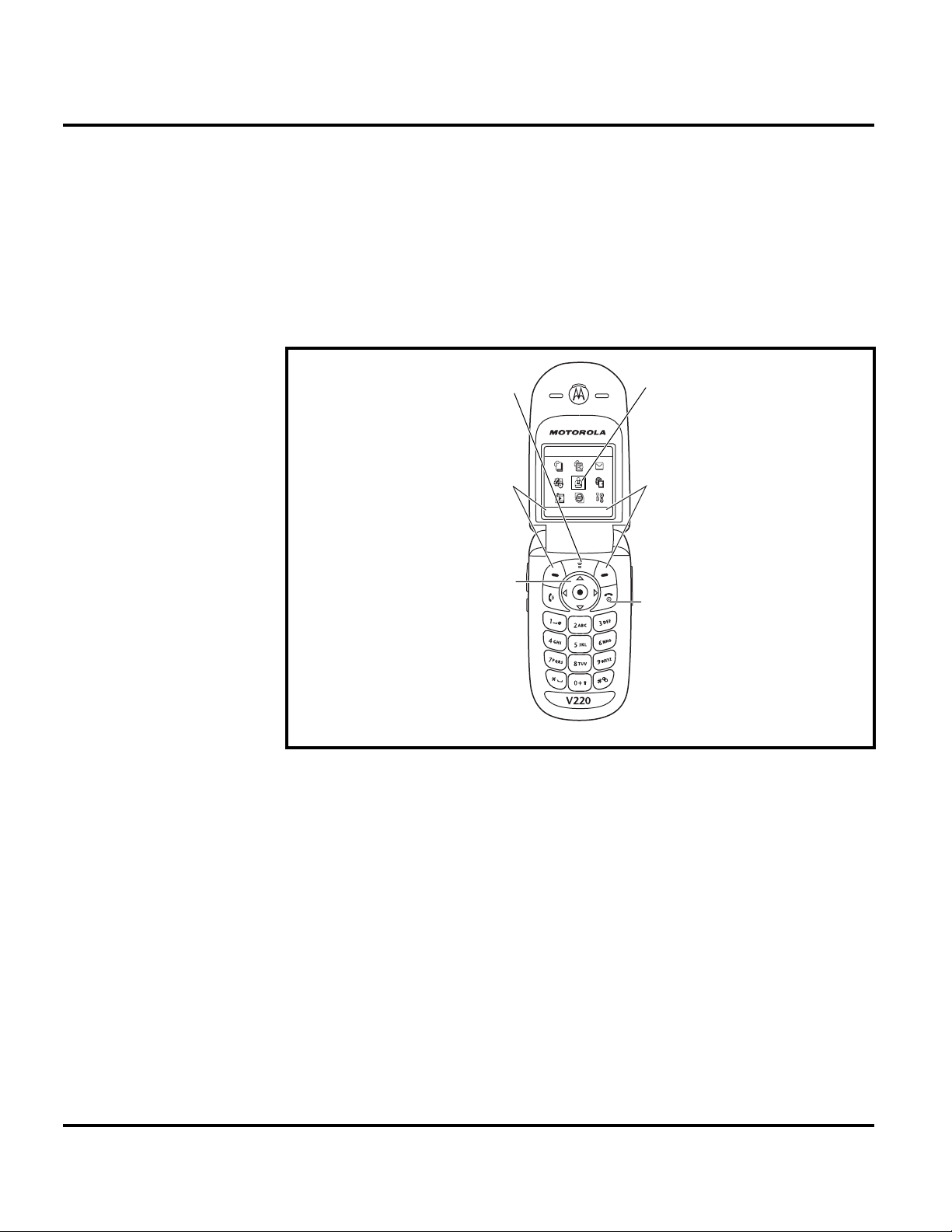
Controls, Indicators, and Input / Output (I/O) Connections
The V220 telephone’s controls are located on the sides of the device and on the
keypad. Indicators, in the form of icons, are displayed on the LCD (see Figure 2).
V220 phones have an audible alert transducer on the top and I/O connectors,
consisting of a headset jack and an accessory port, located on the top and bottom of
the phone. See Figure 1.
Menu Key
Enter menu
system
Left Soft Key
Perform left
function.
5-Way
Navigation Key
Scroll up, down,
left, or right.
Press center to
perform right
softkey function.
032486o
Games & Apps
EXIT SELECT
Highlighted
Menu Feature
Icon
Right Soft Key
Perform right
function.
End Key
Exit menu
without making
changes.
031935o
Figure 1. Controls, indicators, and I/O
“Soft keys” refer to non-labeled keys that correspond to text options displayed on
the screen. The left and right soft keys perform the function shown in the corners
of the display. The right key will usually select an option whereas the left key will
usually exit a function or return to a previous screen.
The menu key opens the initial menu structure, or allows access to a submenu
whenever
M appears on the display.
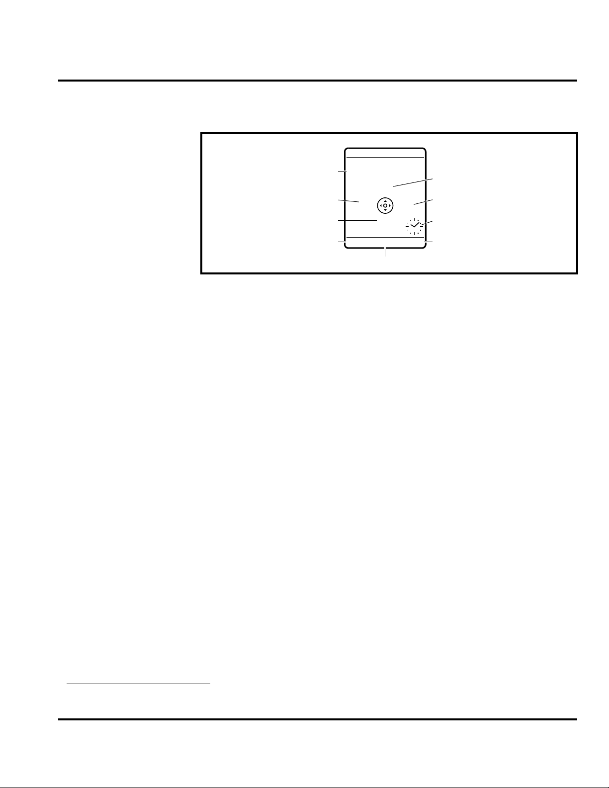
Color Display
The V220 wireless phone features a 65k color CSTN Thin Film Transistor (TFT)
128 x 128 pixel display.The flip contains a 96x32 inverse video CLI display.
14 April 22, 2004 6809480A39-O
Level 1 and 2 Service Manual General Operation
Display animation makes the phone’s menus move smoothly as the user scrolls up
and down.
Turn animation off to conserve the battery.
+49@ ] Ñr(yÉ
Service Provider
10/15/03
Date
Messages
e
Recent Calls
Phonebook
s
à
n
Browser
Clock
Left Soft Key
Label
Figure 2. Icon Indicators
Whether a phone displays all indicators depends on the programming and services
➧
to which the user subscribes.
Figure 2 shows some common icons displayed on the LCD.
• Signal Strength Indicator. Shows the strength of the phone’s connection
with the network. Calls cannot be sent or received when the “no signal” indicator is displayed.
• In Use Indicator. Appears when a call is in progress.
• Roam Indicator.
side the user’s home network. When leaving the home network area, the phone
roams, or seeks another network.
• Message Waiting Indicator.
sage. This is a network-dependent feature.
• Voice Message Waiting Indicator.
received. This is a network-dependent feature.
• Battery Level Indicator. Shows the amount of charge left in the battery. The
more segments visible, the greater the charge. Recharge the battery as soon as
possible when the Low Battery warning message appears.
• Clock. Shows the current date and time.
• Menu Indicator. Indicates the user can press the menu soft key to open a
menu.
• Alert Setting Indicator. Shows the current selected alert. The default alert
setting is a ringer.
5
Appears when the phone uses another network system out-
STYLES
M
CAMERA
Menu Indicator
5
Appears when the phone receives a text mes-
1
Appears when a voicemail message is
Right Soft Key
Label
031939o
1. Network, subscription and SIM card or service provider dependent feature. Not available in all areas.
6809480A39-O April 22, 2004 15

General Operation V220
S
User Interface Menu Structure
Figure 3 shows the telephone menu structure.
Main Menu
Q
Games & Apps
h
Multimedia
É
Tools
w
Settings
ã
IM
á
Web Access
n
Phonebook
s
Recent Calls
e
Messages
K
Chat
This is the standard main menu layout.
Menu organization and feature names
may vary on your phone.
Not all features may be available for all users.
es
Them
Camera
Pictures
Sounds
MotoMixer
SIM Apps
Calculator
Datebook
Shortcuts
Records
Voice
Alarm
Clock
Dialing Services
Call Barring
Fixed
Service Dial
Quick
(see next page)
Browser
Web Shortcuts
Stored Pages
History
Go
To URL
Web Sessions
Browser
Setup
Received Calls
Dialed Calls
Notepad
Call Times
Call Cost
Data
Times
Data
Volumes
Create Message
Voicemail
Message Inbox
Email Msgs
Browser
Msgs
Info Services
Quick
Notes
Outbox
Drafts
Dial
Dial
ettings Menu
l
Personalize
Home Screen
Menu
Main
Color Style
Greeting
Wallpaper
Screen Saver
Dial
Quick
t
Ring Styles
Style
Style
Detail
My
Tones
L
Connection
Sync
H
Call Forward
Voice Calls
Fax
Calls
Data Calls
Cancel All
Forward Status
U
In-Call Setup
Z
Initial Setup
m
Phone Status
S
Headset
J
Car Settings
j
Network
u
Security
c
Java Tools
Timer
In-Call
Call Cost Setup
My Caller ID
Talk and Fax
Answer
Options
Call Waiting
Time and Date
1-Touch Dial
Backlight
TTY Setup
Scroll
Language
Battery Save
Contrast
DTMF
Master
Reset
Master
Clear
My
Tel. Numbers
Credit Info/Available
Active Line
Battery Meter
Other Information
Phone Lock
Lock Application
Fixed
Dial
Call Barring
SIM Pin
New
Passwords
Java App Loader
Java
System
Java
Debug
TCK
Start
Remove All Midlets
031954o
Figure 3. Menu Structure
16 April 22, 2004 6809480A39-O
 Loading...