

Page 1
3UHOLPLQDU\
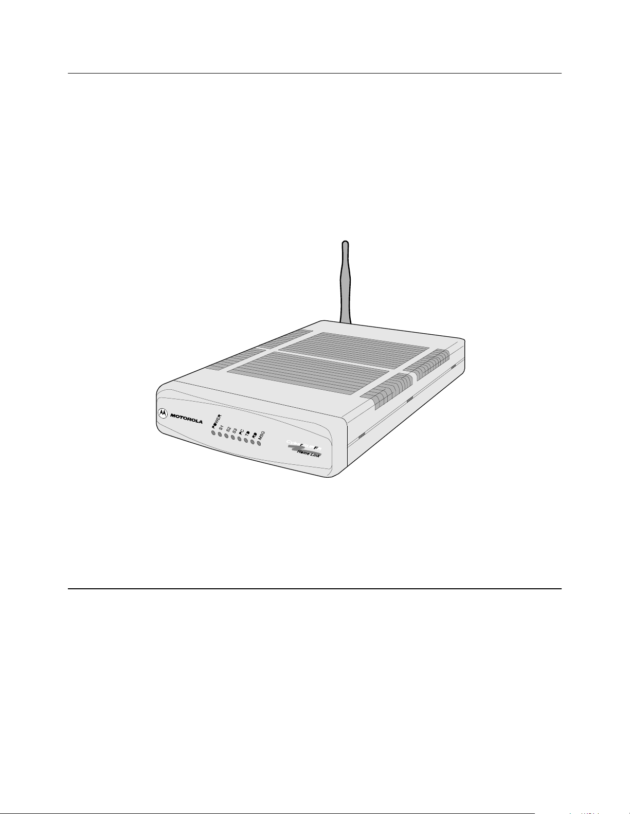
Motorola AL 200 Multi-User Modem
Installation Manual
Page 2

Notice
©2000 Motorola, Inc.
20 Cabot Boulevard
Mansfield, Massachusetts 02048
(508) 261-4000
All rights reserved
Printed in U.S.A.
Restricted Rights Notification for U.S. Government Users
The software (including firmware) addressed in this guide is provided to the U.S.
Government under agreement which grants the government the minimum “restricted rights”
in the software, as defined in the Federal Acquisition Regulatio n (FAR) or the Defense
Federal Acquisition Regulation Supplement (DFARS), whichever is applicable.
If the software is procured for use by the Department of Defense, the following legend
applies:
Restricted Rights Legend
Use, duplication, or disclosure by the Government
is subject to restrictions as set forth in
subparagraph (c)(1)(ii) of the
Rights in Technical Data and Computer Software
clause at DFARS 252.227 -70 13 .
If the software is procured for use by any U.S. Government entity other than the Department
of Defense, the following notice applies:
Notice
Notwithstanding any other lease or license agreement that may pertain to,
or accompany the delivery of, this computer software, the rights of the
Government regarding its use, repr odu cti o n, and disclos ure are as set forth
in F A R 52.227 -19 (C ).
Unpublished - rights reserved under the copyright laws of the United States.
Page 3

Notice (continued)
Proprietary Material
Information and software in this document are proprietary to Mo torola, Inc. (o r its Suppliers)
and without the express prior permission of an officer of Motorola, may not be copied,
reproduced, disclosed to others, publi s hed, or used, in whol e or i n p art , f or any purpose other
than that for which it is being made available. Use of soft ware de scribed in this document is
subject to the terms and conditions of the Motorola Software License Agreement.
This document is for information purposes only and is subject to change without notice.
Radio Frequency Interference Regulations
This equipment has been tested and found to comply with the limits for a Class B digital
device, pursuant to Part 15 of the FCC Rules. These limits are designed to provide reasonable
protection against interference in a residential installation. This equipment generates, uses,
and can radiate radio frequency energy and, if not installed and used in accordance with the
instructions, may cause harmful interference to radio communications. However, there is no
guarantee that interference will not occur in a particular installation. If this equipment does
cause harmful interference to radio or television reception, which can be determined by
turning the equipment off and on, the user is encouraged to try to correct the interference by
one or more of the following measures:
– Reorient or relocate the receiving antenna.
– Increase the separation between the equipment and receiver.
– Connect the equipment into an outlet on a circuit different from that to which the
receiver is connected.
– Consult the dealer or an experienced radio/TV technician to help.
Changes or modifications not expressly appr oved by Motoro la could void the user's authorit y
to operate the equipment.
Notification of Canadian Requirements
This digital apparatus does not exceed the Class B limits for radio noise emissions from
digital apparatus as set out in the Radio Interference Regulations of the Canadian Department
of Communications.
Le présent appareil numérique n’émet pas de bruits radioélectriques dépassant les limites
applicable aux appareils numériques de classe B prescrites dans le règlement sur le brouillage
radioélectrique édicté par let Ministère des Communications du Canada.
Note to CATV System Installers in the USA
This reminder is provided to call the cable TV system installer’s attention to Article 820-40
of the National Electrical Code (NFPA 70) that provides guidelines for proper g rounding and ,
in particular, specifies that the cable shield shall be connected to the grounding system in the
building, as close to the point of cable entry as practical.
Part No. 475866-001-00, Rev A. 6/2000 Publication Code:
Page 4

Page 5
About This Manual
Overview
Introduction The Motorola AL 200 Multi-User Modem Installation Manual describes how to
connect, install, and power up a multi-user modem and start a home network.
It also provides basic information about the lights, controls, and connectors on the
multi-user modem.
Audience This manual is intended for the installer of the AL 200.
Software Revision
Level
AL 200 Modem
Documentation Set
Special Notices The following notices emphasize certain information in the manual. Each serves a
This manual is current for R elease 1.0 of the AL 200 firmware.
Motorola provides these manuals to support the AL 200:
• Motorola AL 200 Multi-User Modem Installation Manual
• Motorola AL 200 Multi-User Modem On-line Help in the Network Manager
application
special purpose and is displayed in the format shown.
Caution
Caution provides you with information that, if not followed, can result in damage to
software, hardware, or data.
Warning
Warning is the most serious notice, indicating that you can be physically hurt.
Trademarks Motorola A L 200 is a trademark of Motorola , Inc.
Windows is either a registered trademark or trademark of Microsoft Corporation in
the United States and/or other countries.
Year 2000 Ready The AL 200 is year 2000 ready.
v
Page 6

About This Manual (continued)
Important Safety Notices
These are important safety instructions:
• Read Instructions
Read all the safety and operating instructions before you operate the product.
• Retain Instructions
Retain the sa fety and operating instruct ions for future reference.
• Heed warnings
Adhere to all the warnings on the product and in the operating instructions.
• Follow in structions
Follow all operating and use instructions.
• Cleaning
Unplug this product from the AC power before cleaning. Do not use liquid
cleaners or aerosol cleaners. Use a dry cloth for cleaning.
•Attachments
Do not use attachments not recommended by the product manufacturer as
they may cause hazards.
• Water and Moisture
Do not use this product near water — for example, near a bath tub, wash
bowl, kitchen sink, or laundry tub, in a wet basement, or near a swimming
pool; and the like.
• Power Sources
Operate this product only from the type of power source indicated on the
marking label of the power supply (or power plug). If you are not sure of the
type of power supply, consult your product dealer or local power company.
For products intended to operate from other sources, refer to the specific
operating instructions.
• Power-Cord Protection
Route the power supply cords so that they are not likely to be walked on or
pinched by items placed upon or against them. Pay particular attention to
cords at plugs, convenience receptacles, and the point where they exit from
the product.
• Replacement Parts
There are no replacement parts. If necessary, the modem is replaced with a
new modem.
•Heat
Situate the product away from heat sources such as radiators, heat registers,
stoves, and other products that produce heat.
• Rain or moisture
To prevent fire or shock hazard, do not expose this unit to rain or moisture.
vi
Page 7

About This Manual (continued)
• Damage Requiring Service
Unplug this product from the wall outlet and refer servicing to qualified
service personnel under the following conditions:
- The power supply cord or plug is damaged.
- Liquid has been spilled, or objects have fallen into the product.
- The product has been exposed to rain or water.
- The product does not operate normally by following the operating
instructions.
- The product has been dropped or the cabinet has been damaged.
- The product exhibits a distinct change in operation.
• Ventilation
Holes on the top and side of the modem provide ventilation thereby ensuring
reliable operation of the product by protecting it from overheating. Do not
block or cover these openings. Do not block the openings by placing the
product on a bed, sofa, rug, or other similar surface. Do not place the product
in a built-in installa tion such a s a bookcase or rack unle ss proper ve ntilati on is
provided or the manufacturer’s instructions have been adhered to.
Do not block the unit’s ventilation by placing objects on this product.
• Overloading
Do not overload wall outlets and extension cords as this can result in a fire or
electric shock.
•Unit Location
The AL200 has been certified as a mobile device as per FCC Section 2.1091.
In order to comply with the FCC RF exposure requirements the AL200 must
only be installed with approved ant ennas, and a minimum separ ation di stance
of 20 cm must be maintained from the antenna to any nearby persons.
Customer Support For technica l support within North America, contact Motorola Customer Support at
(800) 544-0062.
For technical support outside of North America, refer to the following World Wide
Web site for your local Motorola representative:
http://www.mot.com/MIMS/Multimedia/cont
vii
Page 8

Page 9

Important Safety Notices .............................................................................. vi
Chapter 1.
The Motorola AL 200 Multi-User Modem
About the Motorola AL 200 Multi-User Modem ......................................... 1-2
Preparing for Installation .............................................................................. 1-4
Installing the AL 200 .................................................................................... 1-7
Installing Motorola’s Net Manager Software ............................................... 1-12
Training the Subscriber to Use the AL 200 .................................................. 1-13
Appendix A.
Specifications
Appendix B.
Connector Pinouts
Using the Ethernet Port ................................................................................ B-3
Contents (continued)
Appendix C.
Front and Back Panels
LEDs ............................................................................................................. C-2
Appendix D.
Regulatory Information
Glossary
ix
Page 10

Contents (continued)
x
Page 11

Chapter 1
The Motorola AL 200 Multi-User Modem
Overview
Introduction This chapter introduces the Motorola AL 200 Multi-User Modem.
The Motorola AL 200 Multi-User Modem 1-1
Page 12
About the Motorola AL 200 Multi-User Modem
About the Motorola AL 200 Multi-User Modem
Introduction Motorola’s AL 200 Multi-User Modem enables you to access the Internet over
broadband cable and share resources in your own home network.
The AL 200 connects computers and other devices in a home or small office
network, and connects a your persona l comp uters, workstati ons, or hu b to the h ybrid
fiber/coaxial (HFC) system. After you connect the AL 200 to the HFC network,
install Motorola’s net manager software on the computers, and make logical
connections, you can:
• Share local files and resources on the local network
• Access remote network services, including the Internet and the World Wide
Web, from multiple computers, simultaneously
Local Network Hub In conjunction with br oadb and Int ernet acces s, or wi thout i t, the AL 200 per forms a s
a network hub, enabling the computers in your home to communicate with one
another. The computers on the home network must each have suitable network
adapters (hardware) and network drivers (software). This guide explains how to
install the hardware and software, and describes the available options and
configurations.
Together, the AL 200’s networking and broadband Internet access features form a
solution for a home or office that is powerful, yet easy to set up and to use.
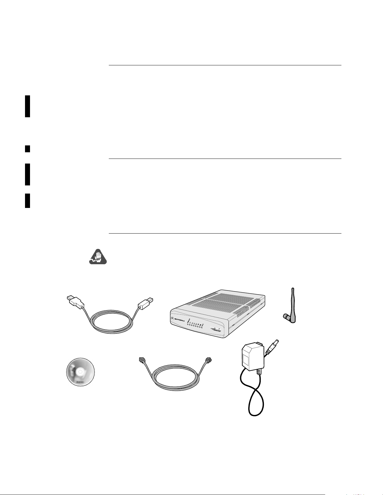
Components Figure 1-1 shows the AL 200 and its packaged components.
Warning
For your safety, do not open the AL 200. There are no serviceable parts in the unit.
Refer all service to qualified service personnel.
USB Male/Female
Cable
Motorola Home Net
Manager Software
CD-ROM
Straight-through
Ethernet Cable
AL200
Multi-User Modem
Wall-Mount Transformer
Antenna
Power-Supply
Figure 1-1. Motorola AL 200 Multi-User Modem Components
1-2 The Motorola AL 200 Multi-User Modem
Page 13

About the Motorola AL 200 Multi-User Modem
The Motorola AL 200 Multi-User Modem 1-3
Page 14

Preparing for Installation
Preparing for Inst allation
Introduction This section describes how to prepare for AL 200 installation.
Local
Requirements
Comput er or
Workstation
Requirements
Before installation, ensure that:
• Your cable service includes broadband Internet access
• The service is functioning properly
• The coaxial cable is installed and active in the room where the AL 200 is
located
• The site chosen for the AL 200 installation is within an appropriate distance
of a power source and that the site is free of accumulated dust and environmental extremes
Before installation, decide which computer(s) to connect to the network and
determine the type of adapter to use for each computer. The next section provides
further information.
Each computer or workstation must have hardware and software to establish a
connection with the AL 200.
Verify that the components listed in this section for the computer’s network
connection type are installed. The network connection types are:
•RF/USB
• RF/PCMCIA
•Ethernet
1-4 The Motorola AL 200 Multi-User Modem
Page 15
Preparing for Installation
RF/USB Connection
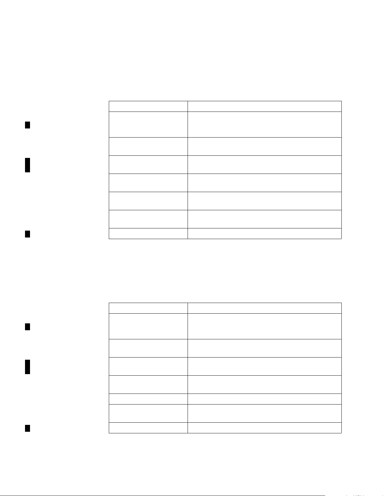
The computer connects to the AL 200 with a wireless Home RF USB adapter. This
device plugs into the computer’s USB connector and communicates on the RF
spectrum with the AL 200.
For an RF/USB connection, th ese compon ents must be inst alle d and avai labl e on the
computer:
Component Description
Network driver Software that lets you connect the AL 200 to the
communications software. This software is included
with the Home RF adapter.
TCP/IP network protocol Software installed as par t of the operating system that
lets computers communicate on a network
Wireless HomeRF USB
adapter
Device with an antenna and receiver that plugs into
USB port
Data applic ation Software that lets you connect to the Internet; for
example, a Web browser or FTP
USB port Port that meets USB standards to connect to a USB
peripheral
Windows
98 Operating system. Files from the system disk are
needed for the AL 200 installation.
Windows Networking Software for communication among computers
RF/PCMCIA Connection
The computer connects to the AL 200 with a wireless Home RF PCMCIA adapter.
This device plugs into the computer’s PCMCIA port and communicates on the RF
spectrum with the AL 200.
For an RF/PCMCIA connection, these components must be installed and available
on the computer:
Component Description
Network driver Software that lets you connect the AL 200 to the
communications software. This software is included
with the Home RF adapter.
TCP/IP network protocol Software installed as par t of the operating system that
lets computers communicate on a network
Wireless HomeRF
PCMCIA adapter
Device with an antenna and receiver; plugs into
PCMCIA port
Data applic ation Software that lets you connect to the Inte rnet; for
example, a Web browser or FTP
PCMCIA port Port that meets PCMCIA standards
Windows
95 or 98 Operating system. Files from the system disk are
needed for the AL 200 installation.
Windows Networking Software for communication among computers
The Motorola AL 200 Multi-User Modem 1-5
Page 16
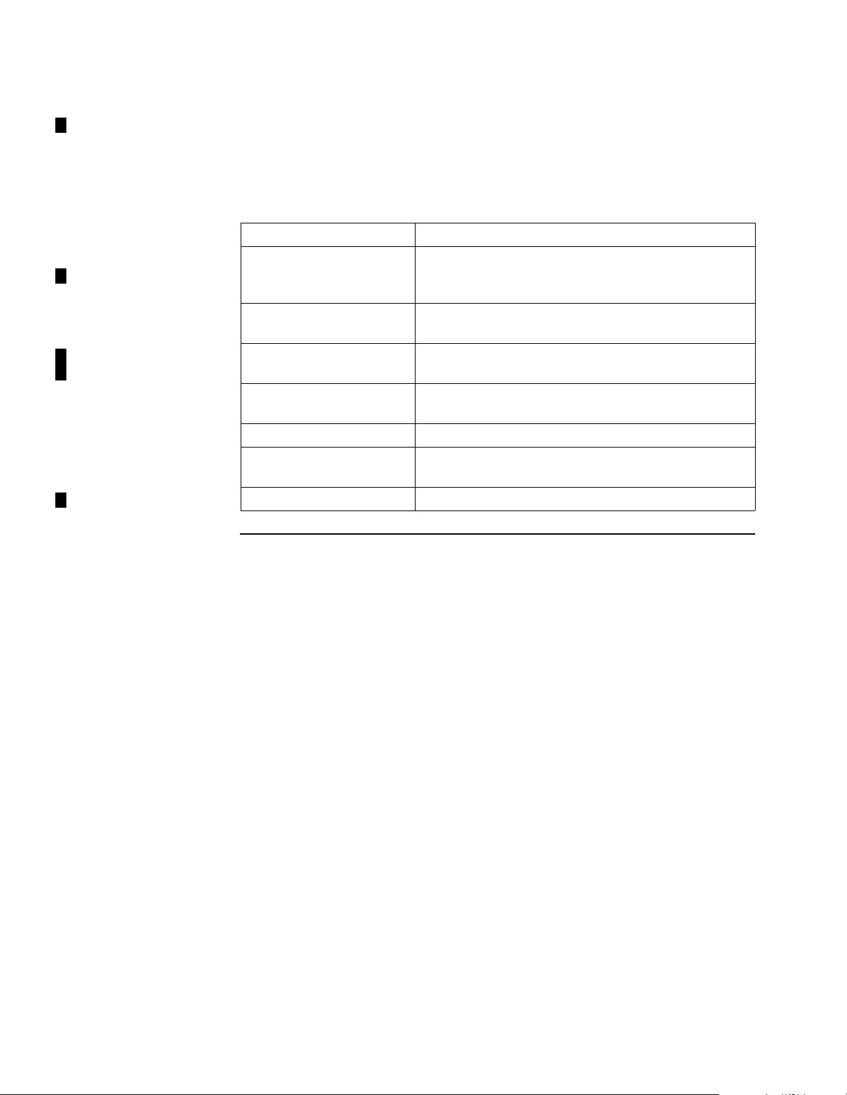
Preparing for Installation
Ethernet Connection
The computer connects to the AL 200 with an Eth ernet network adap ter. This device
plugs into the computer’s Ethernet port (on the adapter card) and communicates on
the Ethernet cable with the AL 200.
For an Ethernet connection, the se component s must be inst alle d and availabl e on the
computer:
Network driver Software that lets you connect the AL 200 to the
TCP/IP network protocol Software installed as par t of th e ope rating system that
Ethernet network adapter Device with an antenna and receiver; plugs into
Data applic ation Software that lets you connect to the Inte rnet; for
Ethernet port Network card port that meets Ethernet standards
Windows
Component Description
communications software. This software is included
with the Ethernet adapter.
lets computers communicate on a network
Ethernet port
example, a Web browser or FTP
95 or 98 Operating system. Files from the system disk are
needed for the AL 200 installation.
Windows Networking Software for communication among computers
1-6 The Motorola AL 200 Multi-User Modem
Page 17
Installing the AL 200
Introduction This section explains how to:
• Make antenna and cabl e c onne ct ion s t o t he AL 200, and power it up—see the
“AL 200 Antenna Connection” section on page 1-7.
• Connect computers to the AL 200:
- To conne ct the AL 200 to each compute r with a wireless Home RF adapter,
see the “Wireless Computer Connections” section on page 1-8
- To connect the AL 200 to one computer using a higher-rate Ethernet or
USB cable, see the “Wireline Computer Connections” sect io n on page 1-10
Caution
Ensure that the AL 200 is disconnected from the power outlet during the cabling
procedure, until the step that instructs you to connect it.
T o turn the AL 200 on or off, connect or disc onnect the po wer cord at the wal l outlet.
Do not disconnect using the connector at the back of the unit.
Do not operate a AL 200 with an object physica lly lo cated on top. This may result in
damage to the product or injury to the person.
Use the AL 200 only with the appropriate Motorola power supply.
Installing the AL 200
AL 200 Antenna
Connection
The AL200 has been certified as a mobile device as per FCC Section 2.1091. In
order to comply with the FCC RF exposure requirements the AL200 must only be
installed with ap proved antennas, an d a minimum separation dis ta n ce of 20 cm must
be maintained from the antenna to any nearby persons.
Follow these steps:
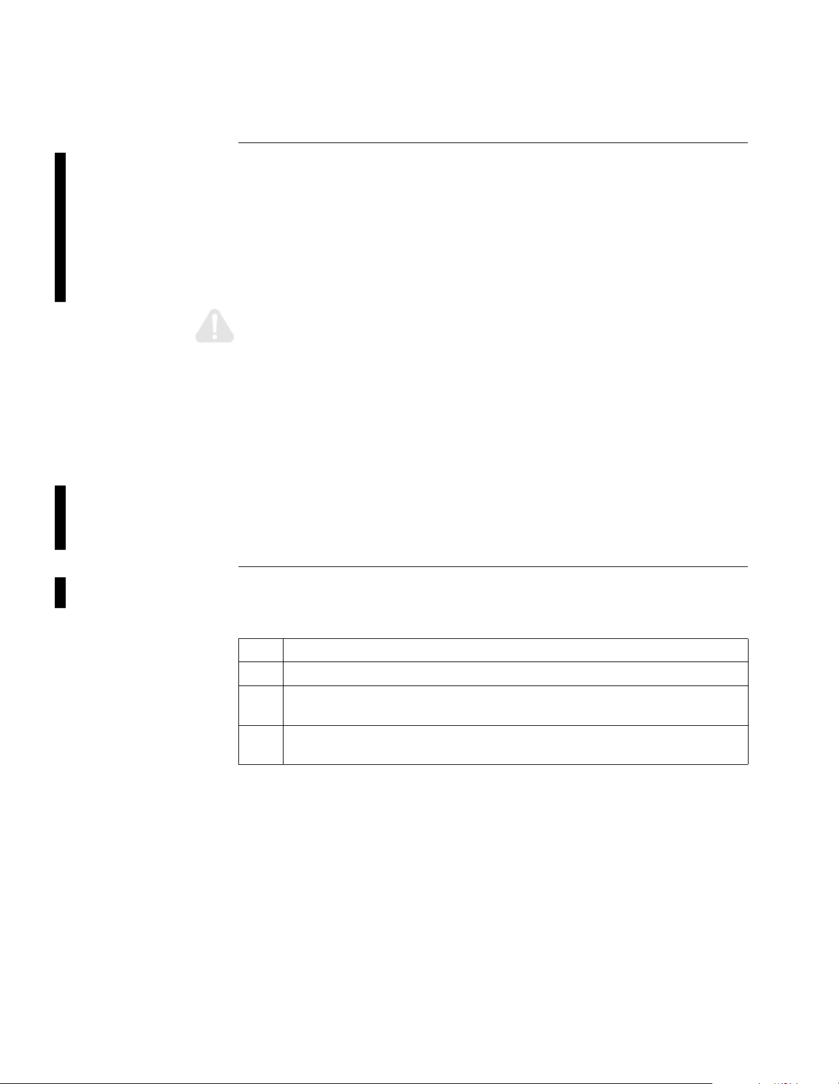
Steps to Connect t he Antenna to the AL 200
Step Action
1 Unpack the AL 200 antenna.
2 Screw the antenna connector into the AL 200 antenna connector until it is
snug.
3 Adjust the antenna elbow joint so that the antenna is vertical when the AL
200 is right side up.
The Motorola AL 200 Multi-User Modem 1-7
Page 18
Installing the AL 200
AL 200 Cable
Connections
Wireless Computer
Connections
Folow these steps.
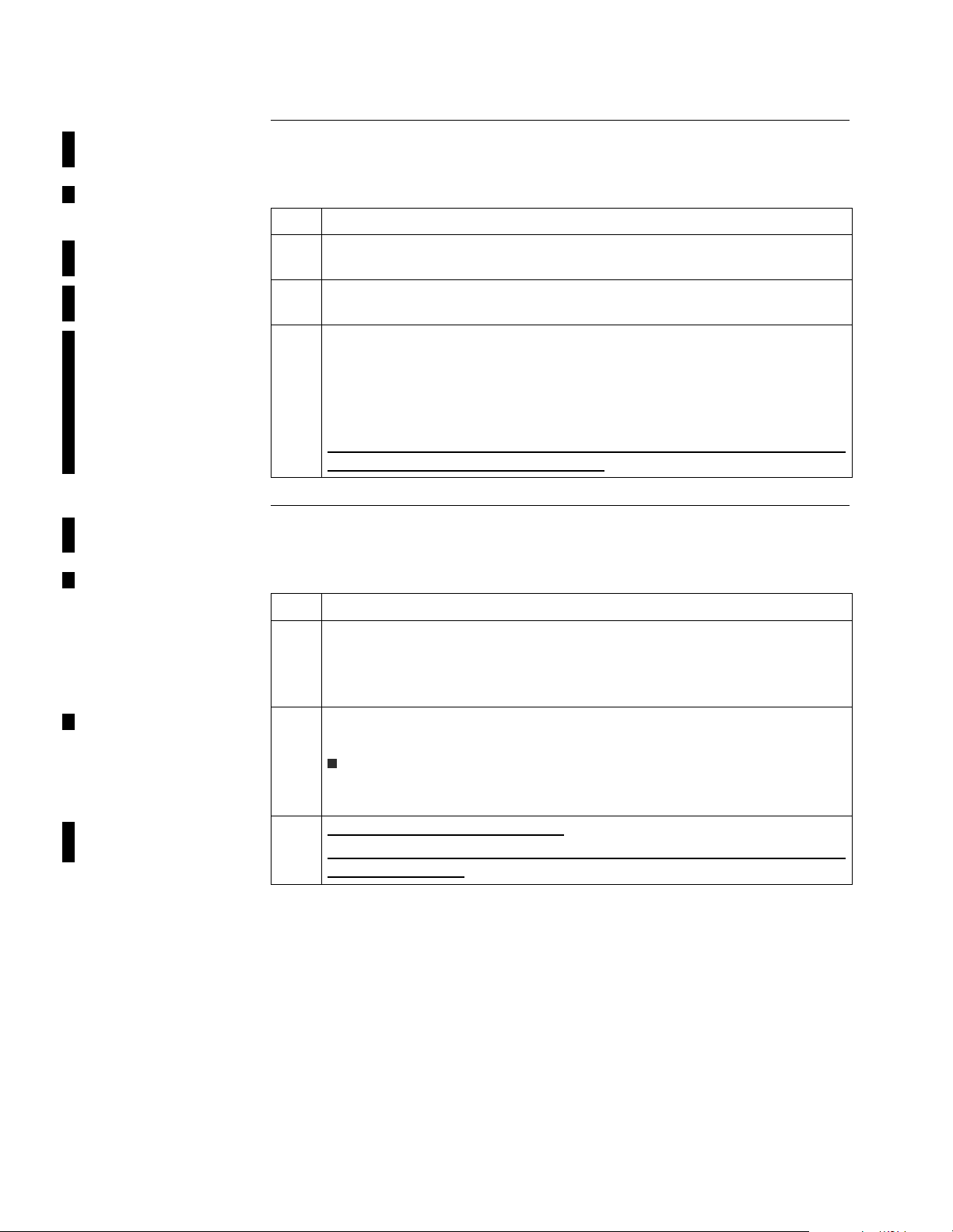
Steps to Connect Home RF on AL 200
Step Action
1 Connect a coaxial cable to the CABLE connector on the back of the AL 200
and to the cable termination point.
2 Connect the power cable to the POWER connector on the back of the AL
200.
3 Plug the wall-mount power supply into a standard electrical outlet.
The LEDs blink in the power-up sequence, then the POWER, S1, S2, and
S3 LEDs remain on. The PC LED goes on, or flickers rapidly, when a
computer is detected on the line.
**/Open Issue/from Mike McGove rn/ AL 200 must b e registerd before PC
can receive IP address/ resolve w/ Mike
Follow these steps for each computer:
Steps to Connect Home RF/USB or RF/PCMCIA Clients
Step Action
1 Connect an RF antenna/adapter to the computer’s USB or PCMCIA port.
Refer to Figure 1-2.
The New Hardware Found dia log box a ppears; the n the Add New Hardware
Wizard window.
2 Click Next. Follow the on-screen instructions. Windows installs the
network adapter driver and the required Windows files.
Note
This step requires the Windows disk. After loading files from the Windows
disk, remove the disk (before restarting the computer).
3 **Set the security ID
?/Mike/Tom
**Tell user not to follow Windws instructions--follow Symph instructions-
-for driver in stall??
1-8 The Motorola AL 200 Multi-User Modem
Page 19
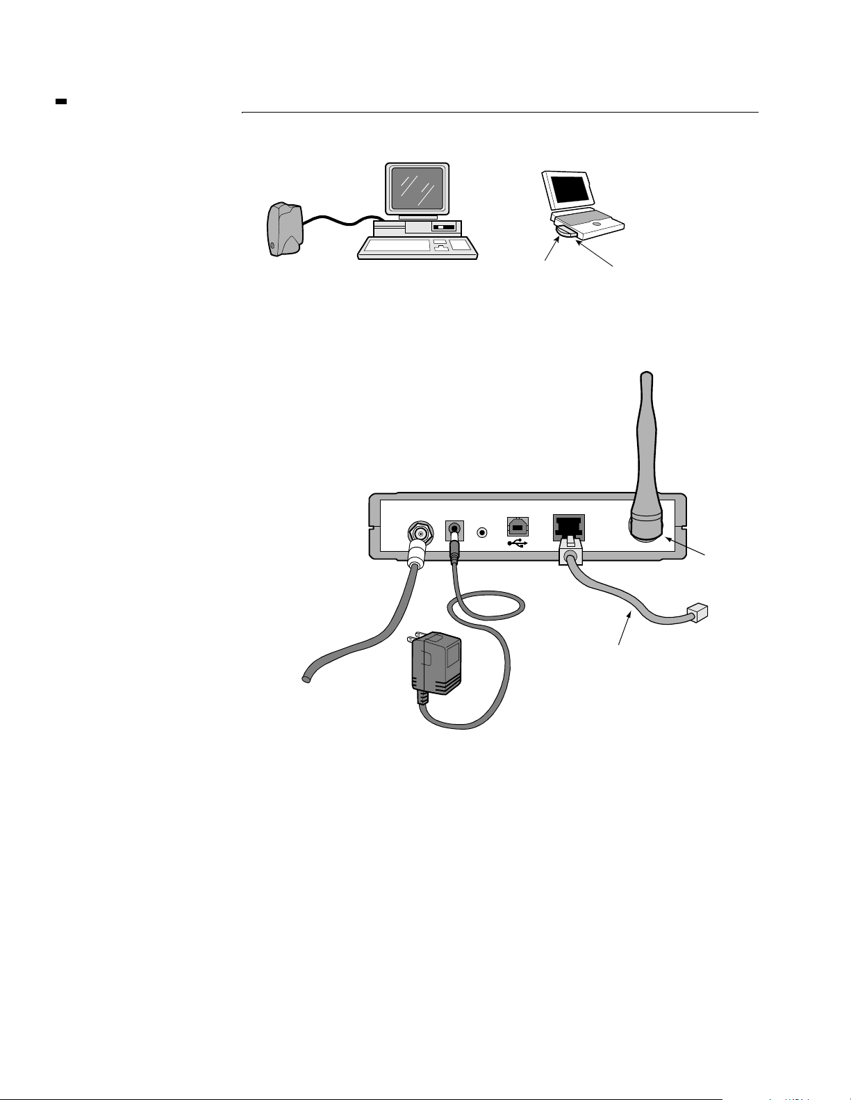
What You See Figure 1-2 shows examples of Home RF connections.
Installing the AL 200
Laptop
Computer
Home RF
Antenna/Adapter
Desktop Computer
Home RF
Antenna/Adapter
Network Interface
PCMCIA Connector
Figure 1-2. RF Network Connections, USB and PCMCIA
Figure 1-3 shows AL 200 connections.
ENET
Optional Ethernet Connection
to One Computer
Coaxial Cable
CABLE
POWER
RESET
Antenna
To Directional
Coupler or
Splitter
(if necessary)
Wall-Mount Transformer Power Supply
Figure 1-3. AL 200 Multi-User Modem Cable Connections
The Motorola AL 200 Multi-User Modem 1-9
Page 20
Installing the AL 200
Wireline Computer
Connections
Follow these steps to connect the AL 200 to one computer with Ethernet or USB
cable:
Steps to Connect the AL 200, Wireline Ethernet or USB
Step Action
1 Connect the AL 200 to your computer in one of these ways:
a)For an Ethernet connection, use a Category 5 UTP straight-through
Ethernet cable to connect the Ethernet port on the computer to the
ENET connector on the back of the AL 200.
b)For a USB connection, use a USB cable to connect the USB port on
the computer to the USB connector on the back of the AL 200.
2 Make the connections shown in Figure 1-4 and Figure 1-5.
3 **ISSUE/Check w/ Peg Burbank, Mike McGovrnre another step? Re
USB driver from CD-ROM/ install it/ add a step at appropriate location
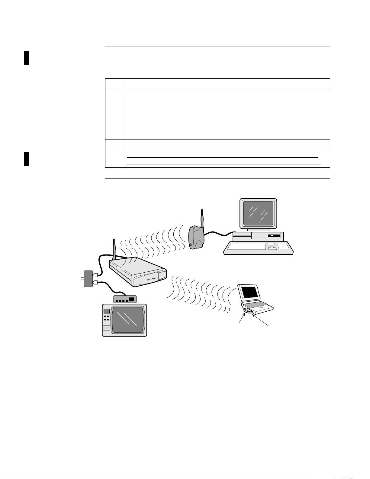
What You See Figures 1-4 and 1-5 show examples of Ethernet connections.
Antennae/Adapter
Home RF
To Cable
Service
Directional
Splitter
or Coupler
Desktop Computer
AL200
Converter
Home RF
Antenna/Adapter
Television
Laptop
Computer
Network Interface
PCMCIA Connector
Figure 1-4. Cable Service and Home Network Connections,
Ethernet/USB
1-10 The Motorola AL 200 Multi-User Modem
Page 21
Installing the AL 200
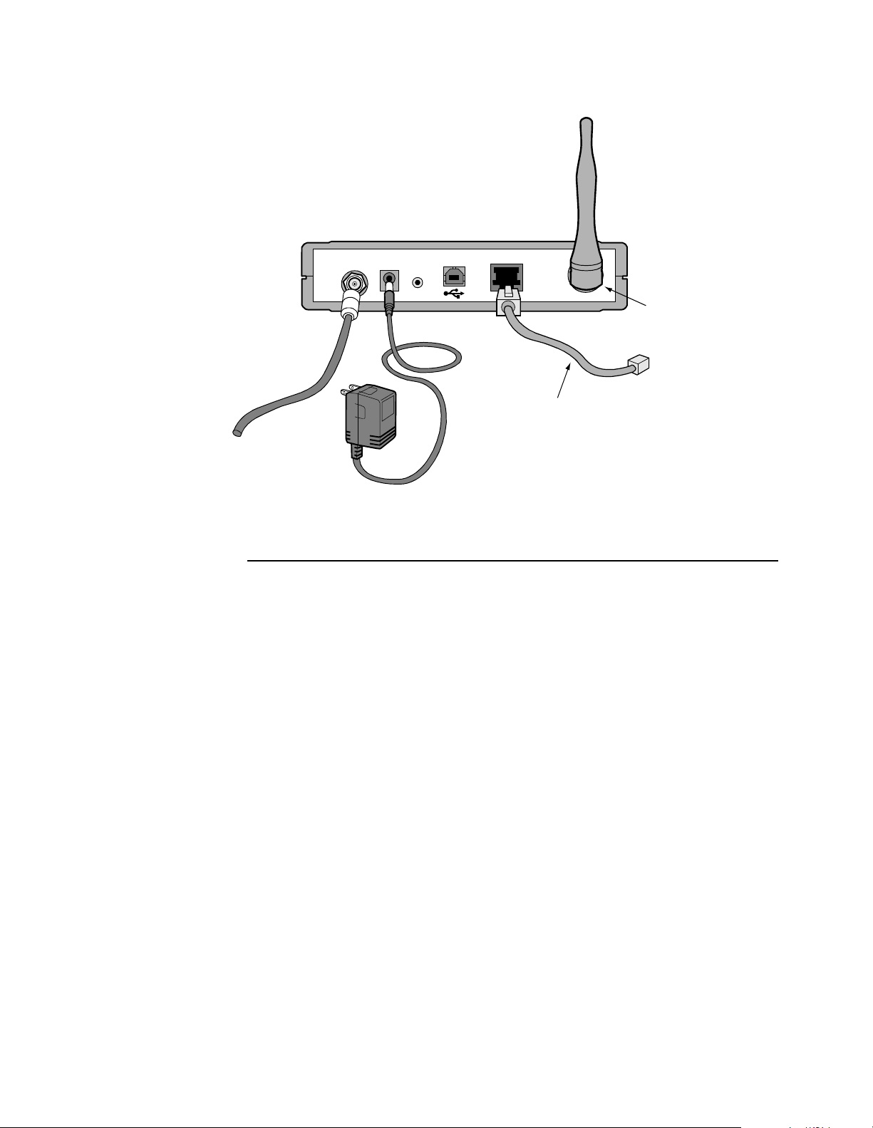
To Directional
Coupler or
Splitter
(if necessary)
CABLE
POWER
RESET
ENET
Antenna
Coaxial Cable
Optional Ethernet Connection
to One Computer
Wall-Mount Transformer Power Supply
Figure 1-5. AL 200 Multi-User Modem Cable Connections
The Motorola AL 200 Multi-User Modem 1-11
Page 22
Installing Motorola’ s Net Manager Software
Introduction When you have completed the tasks in the previous section, perform the following
steps to install the net manager software on each computer in the local network.
Procedure Follow these steps to install the net manager software on each computer:
Step Action
1 Ensure that Microsoft NetBUI and Microsoft Windows Networking are
installed on the computer.
2 Insert the Motorola Net Manage r Software CD-ROM into the CD-ROM
drive.
If auto-run is enabled , the net manage r setup pr ogram begins. Otherwis e,
double click Motorola Net Manager
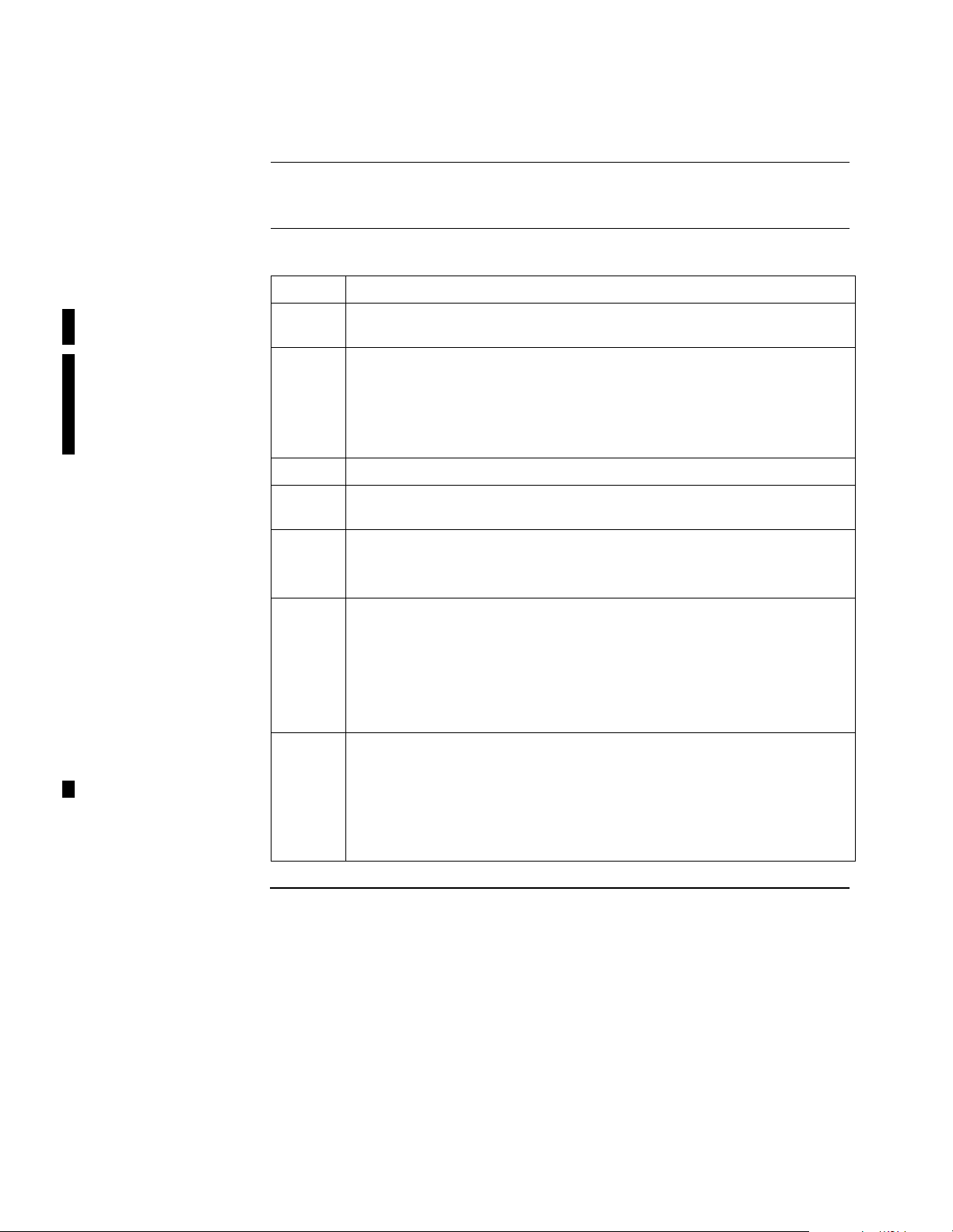
If you need help during the installation, press F1.
3 Follow the setup instructions, which include restarting the computer.
4 When the computer has been re st art ed, the Net Manager Device Shari ng
view appears. This occ urs only after the first restart.
5 Optionally, continue with these steps to change the acces s to one or more
resources. The default setting for each resource is Not Shared.
Close the Network Sharing window.
6 Locate a resource, such as a CD-ROM drive or a printer, in the list.
Click an access setting. For details on access settings, refer to the
“Sharing Resources on a Computer” topic in the net manager on-line
Help.
Click Apply or OK.
Optionally, assign access settings to other resources.
→ setup.exe on the CD-ROM.
7 The Net Manager icon appears in the Windows system tray.
You can run Net Manager to update access settings by double clicking
the Net Manager icon on the Windows Desktop or selecting Start
Programs→ Motorola Network Manager→ Network Manager.
The Network View appears. You can view the devices on the network.
To update access settings, click the Device Sharing tab.
→
Page 23
Training the Subscriber to Use the AL 200
T raining the Subscriber to Use the AL 200
Introduction This section explains how to deli ver basi c t rai ni ng to the ca ble subs cri be r dur ing the
installation visit, and lists the materials to leave with the subscriber.
It is extremely important to train the cable subscriber carefully. Providing clear
instruction during the installation visit will reduce the number of service calls to
subscribers’ homes.
What to Teach the
Subscriber
Starting t he Net
Manager
Opening the Net
Manager On-Line
Help
Troubleshooting Check network connections by running net manager and clicking the Link Test tab.
Contacting
Technical Support
Explain and demonstrate the following to the subscriber:
• How to start the net manager application
• How to open the net manager on-line Help
• Troubleshooting local connections and common problems
• Contacting Technical Support
Run net manager by double clicking its icon or selecting St art
Motorola Network Manager→ Network Manager.
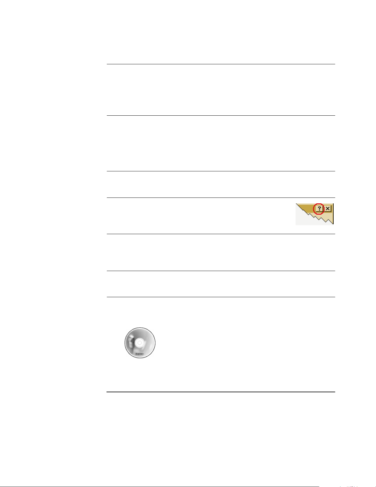
Open the Net Manager on-line Help by double clicking t he Help icon
in the upper right corner of the net manager window.
Trouble shoot problems by not ing changes in the color of the net manager system tray
icon. Refer to the “Troubleshooting” topic in the on-line Help.
If you cannot resolve a proble m, contact Motorola Customer Support, as de scribed in
the “Customer Support” section in the front of this manual.
→ Programs→
Materials for the
Subscriber
At the end of the installation visit, leave the following materials for the subscriber:
• Motorola Net Manager Software CD-ROM
Net Manager CD-ROM
Figure 1-6. Materials for the Cable Subscriber
The Motorola AL 200 Multi-User Modem 1-13
Page 24

Training the Subscriber to Use the AL 200
1-14 The Motorola AL 200 Multi-User Modem
Page 25
Appendix A
Specifications
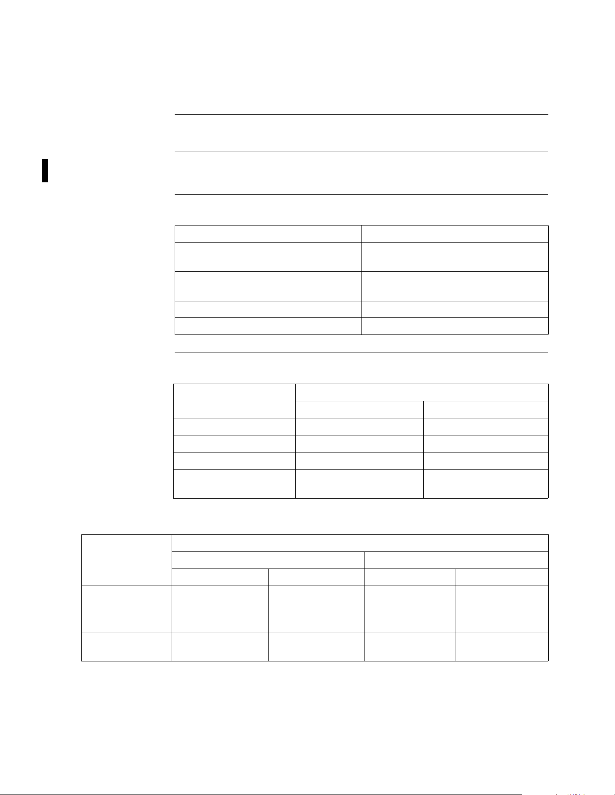
Introduction This section describes the specifications for the Motorola AL 200 Multi-User
Modem.
IP and MAC Layer
Specifications
Physical Layer
Specifications
This table describes the IP and MAC layer specifications for the AL 200.
IP and MAC Layer Specification
MAC performance 16 CPE MAC addresses and eight
downstream encryption SIDs
Upstream bandwidth request Four independent upstream transmit
controllers
Multicast 256 multicast gr oups
Filtering 272 IP filters
This table describes the Physical layer specifications for the AL 200.
Physical Layer
Property
Impedance, return loss 75 Ohms nominal, >6 dB 75 Ohms nominal, >6 dB
Frequency range 5 - 42 MHz 91-857 MHz
Channel assignment Variable center frequencies Standard, IRC, and HRC
Channel bandwidth 200, 400, 800, 1600, and
Upstream Transmitter Downstream Receiver
3200 KHz
Specification
6 MHz for 64QAM and
256QAM
This table describes the physical specifications for each modulation mode.
Physical Layer
Property
16QAM QPSK 64QAM 256QAM
Dynamic range +8 to +55 dBmV +8 to +58 dBmV -20 to +15 dBmV
Symbol rate 160, 320, 640, 1280,
2560 Ksym/s
Specifications A-1
Transmitter Receiver
160, 320, 640, 1280,
2560 Ksym/s
Specification
Typically -25 to
+15 dBmV
5.056941 Msym/s 5.360537 Msym/s
-15 to +15 dBmV
Typically -20 to
+15 dBmV
Page 26
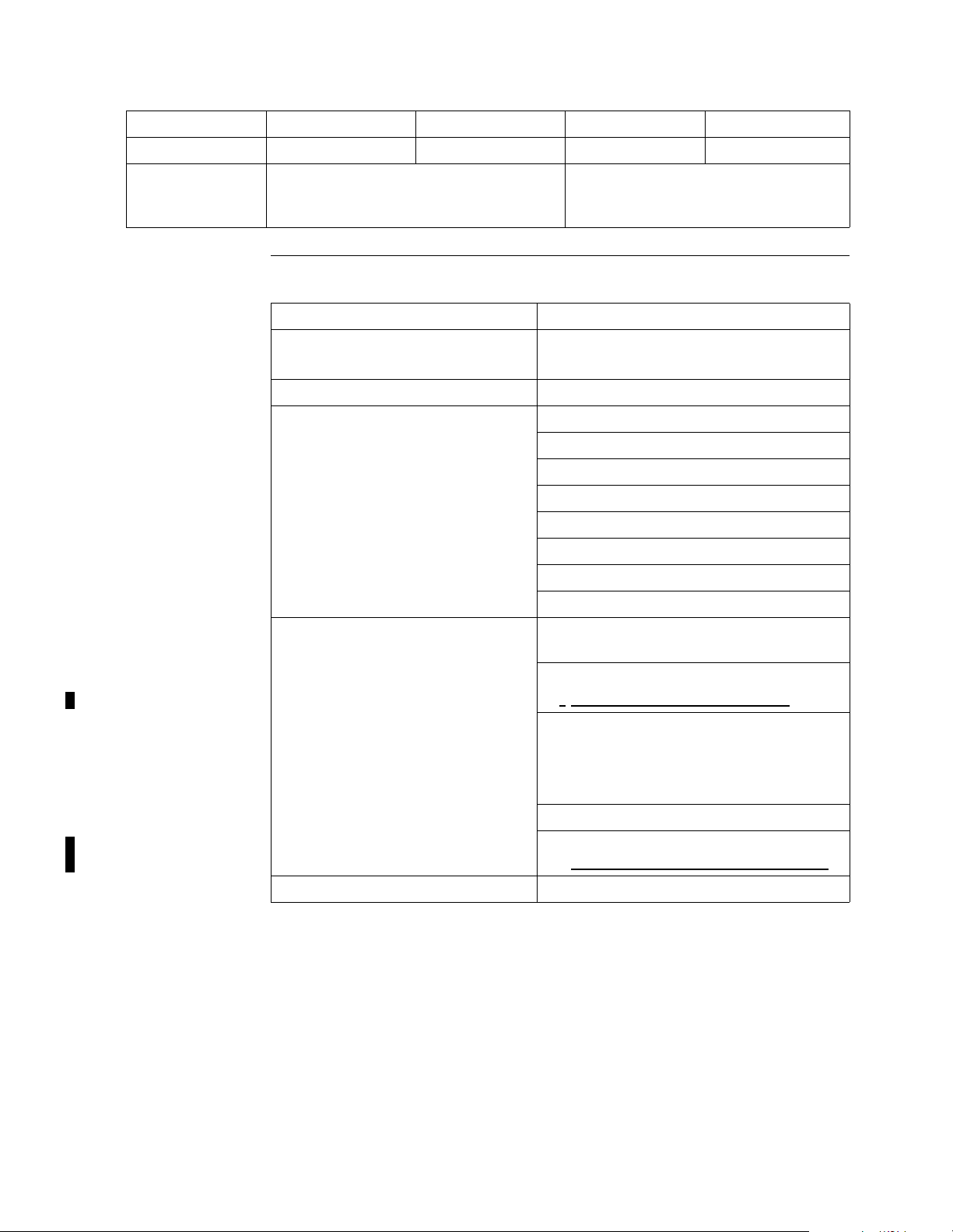
Raw signaling rate 6.4 to 10.24 Mbps .32 to 5.12 Mbps 30.34 Mbps 42.88 Mbps
Information rate 26.97 Mbps 38.81 Mbps
FEC Programmable Reed-Solomon block code Concatenation of Reed-Solomon block
code and Trellis code; ITU J.83-B;
DOCSIS RFI Sec 4.3.2
Physical and
Environmental
This table describes the physical and environmental specifications.
Physical Specification
Dimensions 1.7 in. (H) x 6.8 in. (W) x 10 in. (D)
(43.2 mm x 172.7 mm x 254 mm)
Weight 1.8 pounds (.818 kg)
Front panel LEDs •POWER
• S1 (System connectivity)
• S2 (System connectivity)
• S3 (System connectivity)
• PC (C PE connectivity)
• TRANSMIT (Transmit data)
• RECEIVE (Receive data)
• MESSAGE (programmable message)
Back panel interfac es, connectors an d
controls
• IEC 169-25 RF 75 Ohm threaded
coaxial, Type F
• 120VAC power
•
-->**this is not correct/per Peg
• Reset button, time-triggered dual
function:
– Reset
– Factory se tting
• USB v1.0
•
**need specs for antenna connector
Operating temperature 0o C to +40o C (+32o F to +104o F)
A-2 Specifications
Page 27
Regulatory and
Power
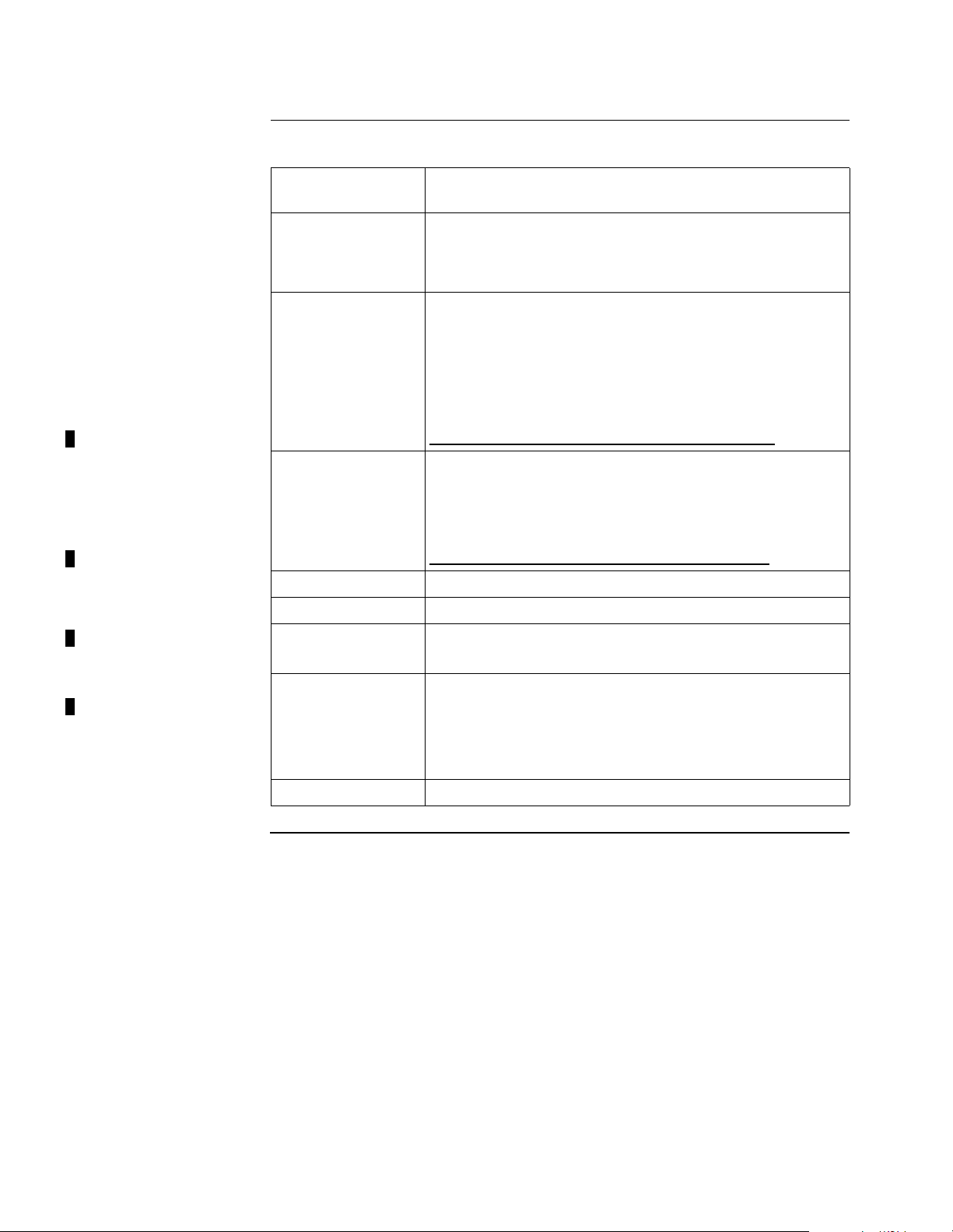
This table describes the regulatory and power specifications.
Regulatory Wall-mount Transformer Power Supply
Specification
Standards
compliance
DOCSIS 1.0
Ethernet/IEEE 802.3
ITU J83-B
Safety UL 1950
CSA C22.2 No. 950
IEC 950
EN 60950
AS/NZS 3260
**last three may be incorrect/Randy Weaner/info
Emissions FCC Part 15, Class B
CISPR 22, Class B
EN 55022, Class B
AS/NZS 3548, Class B
**last four may be incorrect/Randy Weaner/info
Immunity EN 50082-1
Power Input
Power supply, input 120Vac +/-10%, 60 Hz +/- 5%, output +12Vdc at 1.2 A
Auto-ranging 100-240Vac, 47-63Hz
AC/DC power
adapter, output
External Wall-mount Power Supply: Class 2 Type with
NEMA 1-15 plug
External AC/DC power adapter: Class II 2-wire type with
IEC320-C8 inlet, uses country specific power cord with
IEC320-C7 connector
Modem +12Vdc at 1.2 A
Specifications A-3
Page 28

Page 29

Appendix B
Connector Pinouts
Pinouts
Introduction This appendix describes th e connect or pinout requir ements for the Motor ola AL 200
Multi-user Modem.
Ethernet Port
Connector
Ethernet Port This table describes the pinouts for the Ethernet port on the modem. For examples,
Coax Cable
Connector
The Ethernet (ENET) port on the rear panel of the modem is an 8-pin modular
connector. The connector conforms to the IEEE standard for 10/100BaseT access as
defined in 802.3i.
refer to the “Using the Ethernet Port” section on page B-3.
Pin Signal
1 +Receive Data
2 -Receive Data
3 +Transmit Data
4-5 Not Used
6 -Transmit Data
7-8 Not Used
The coax cable connector uses the following pinouts:
• Center conductor — signal
• External conductor — ground
USB Port
Connector
USB Port This table describes the pinouts of the USB port:
Connector Pinouts B-1
The universal serial bus (USB) connector on the rear of the modem is a standard
USB connector. The connector conforms to the USB specifications.
Pin Signal
1+ 5 V
2 Data Negative
3 Data Positive
4Ground
Page 30
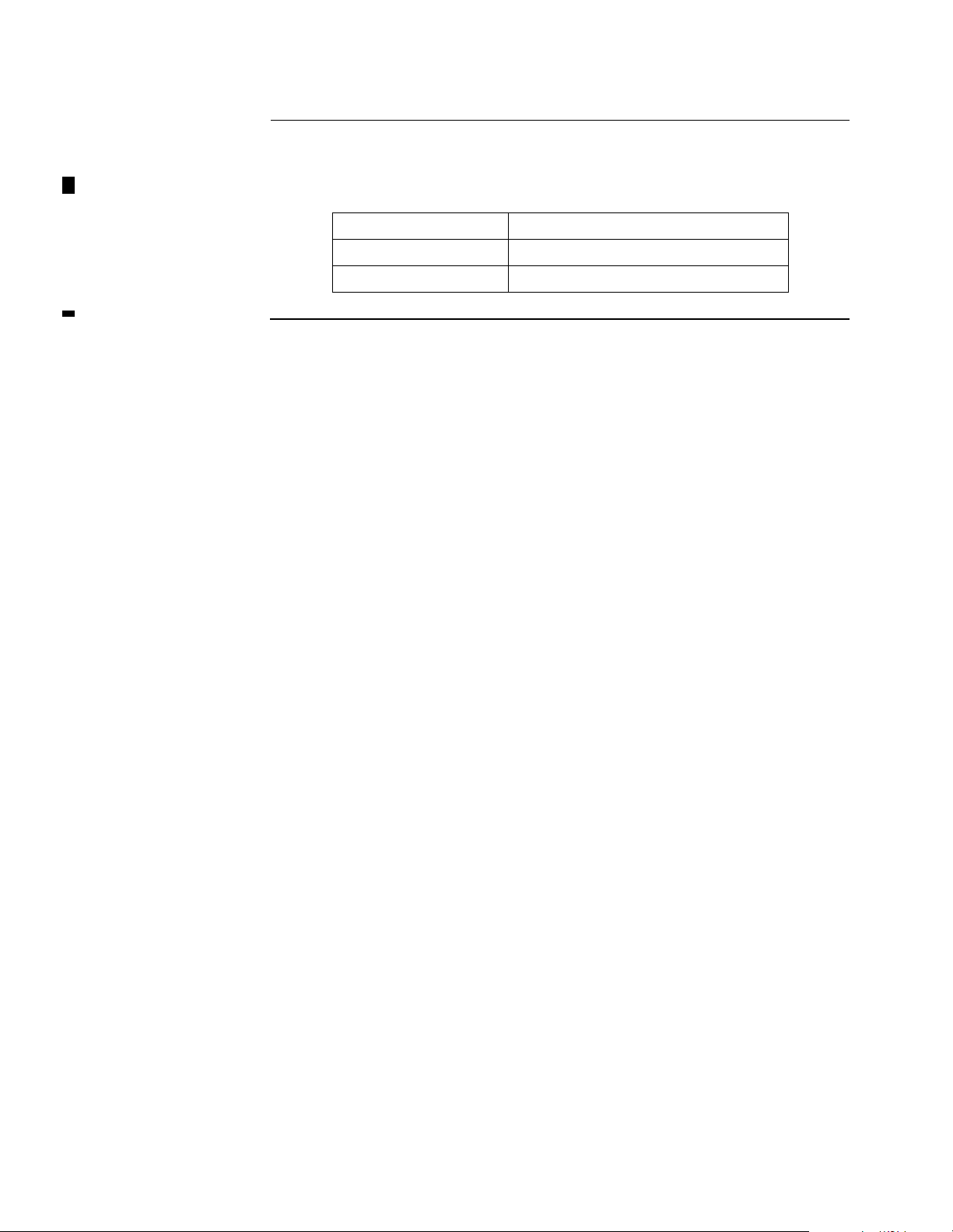
Power Connector The power supply terminates at a two conductor barrel connector on the back of the
AL 200.
This table describes the pinouts for the power connector.
Pin Signal
Outer Contact Ground
Inner Contact +12vdc (nominal)
B-2 Connector Pinouts
Page 31
Using the Ethernet Port
Using the Ethernet Port
Introduction This section shows examples of devices that can be connected to the AL 200 using
an Ethernet connection and the required cabling.
When Y ou Connect
the AL 200 to a PC
When Y ou Connect
the AL 200 to a Hub
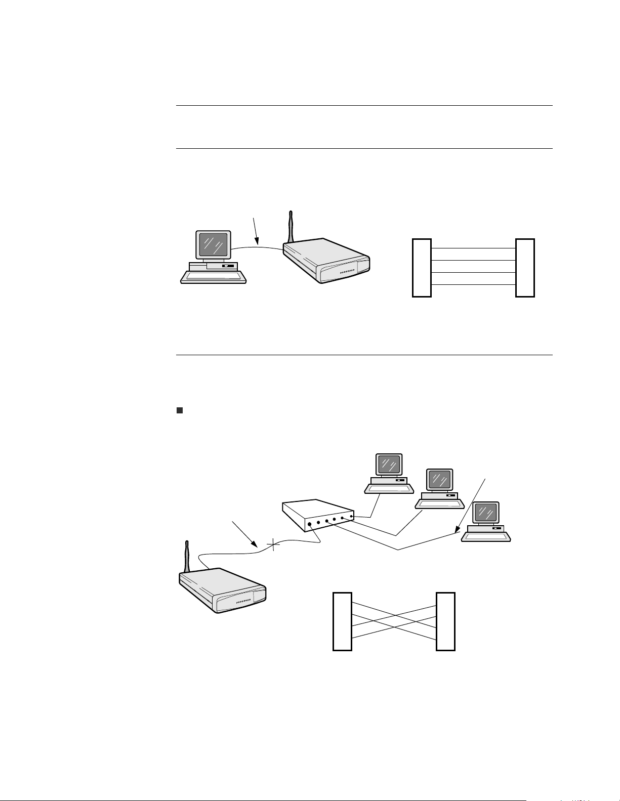
Figure B-1 shows the connection between a cable modem ENET (10/100BT) port
and the Ethernet LAN PC port using a Cat 5 UTP straight-through Ethernet cable.
The wiring diagram is included.
Straight-through
Computer
cable
Modem PC
Multi-User Modem
Wiring Diagram
1
2
3
6
Pins 4, 5, 7, and 8 are unused.
1
2
3
6
Figure B-1. Modem to PC Connection
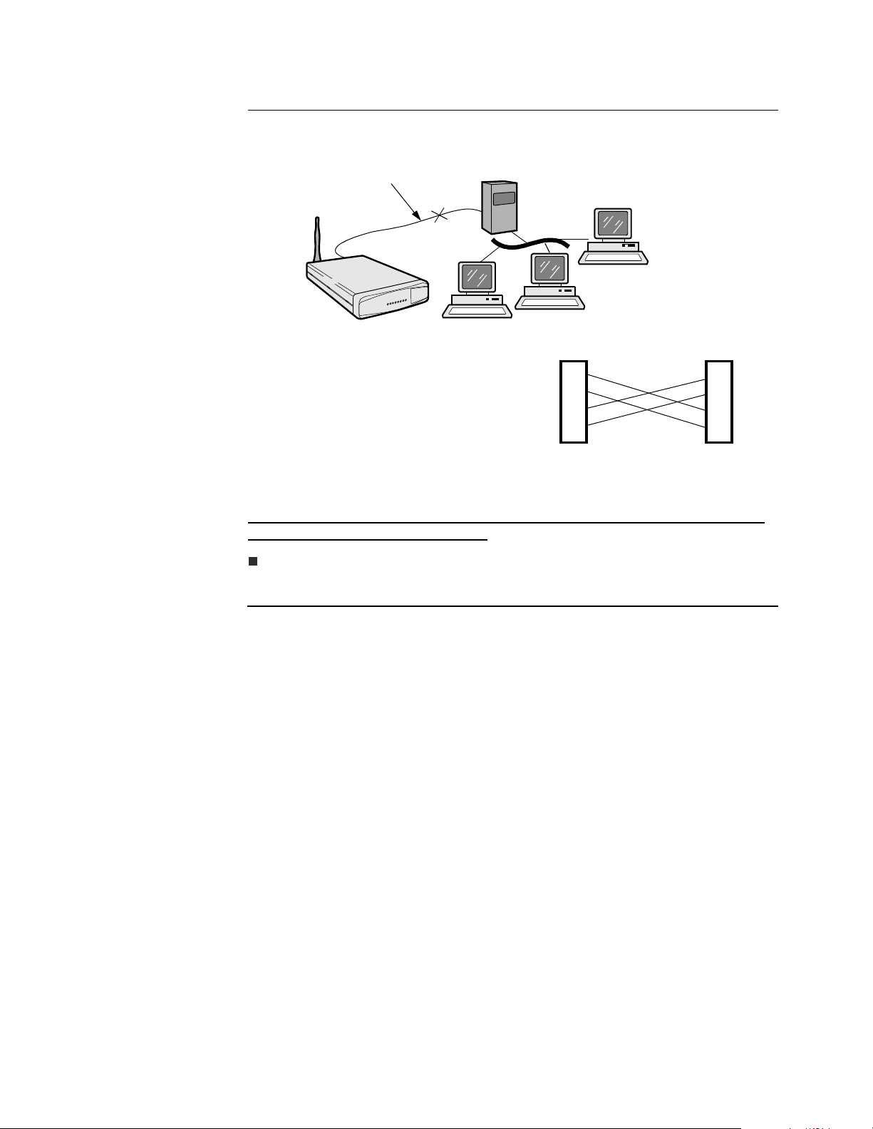
Figure B-2 shows a connection using crossover Ethernet cable (not supplied)
between the AL 200 and a hub. The wiring diagram for the crossover cable is
included.
Note
If the configuration includes an intelligent hub or a hub with an intelligent port,
you may not need crossover cable. Refer to the hub documentation.
Straight-through cable
Crossover cable
Multi-User Modem
Hub
Modem Hu b
1
2
3
6
Pins 4, 5, 7, and 8 are unused.
PC
PC
PC
Wiring Diagram
1
2
3
6
Figure B-2. Modem to Hub Connection
Connector Pinouts B-3
Page 32
Using the Ethernet Port
When Y ou Connect
the AL 200 to a
Customer Premise
Router
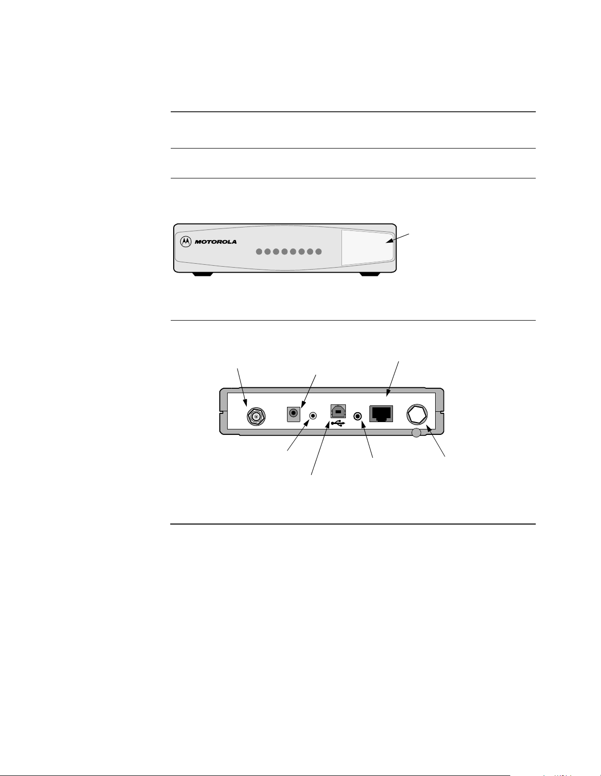
Figure B-3 shows a connection between the AL 200 and a customer premise router
using a crossover Ethernet cable (not supplied). The wiring diagram is included.
Crossover cable
Multi-User Modem
Customer Prem i s e R ou ter
PC
PC
Modem
Pins 4, 5, 7, and 8 are unused.
PC
Wiring Diagram
1
2
3
6
Hub
1
2
3
6
Figure B-3. Modem to Customer Premise Router Connection
***MIkeMcg/wants to represent bridging here? Get sketch from him; have Tim
Kinch update the graphic; paste it in.
Note
This set-up may require configuration by the service provider.
B-4 Connector Pinouts
Page 33
Appendix C
Front and Back Panels
Introduction This appendix describes the AL 200 front and back panel lights and buttons.
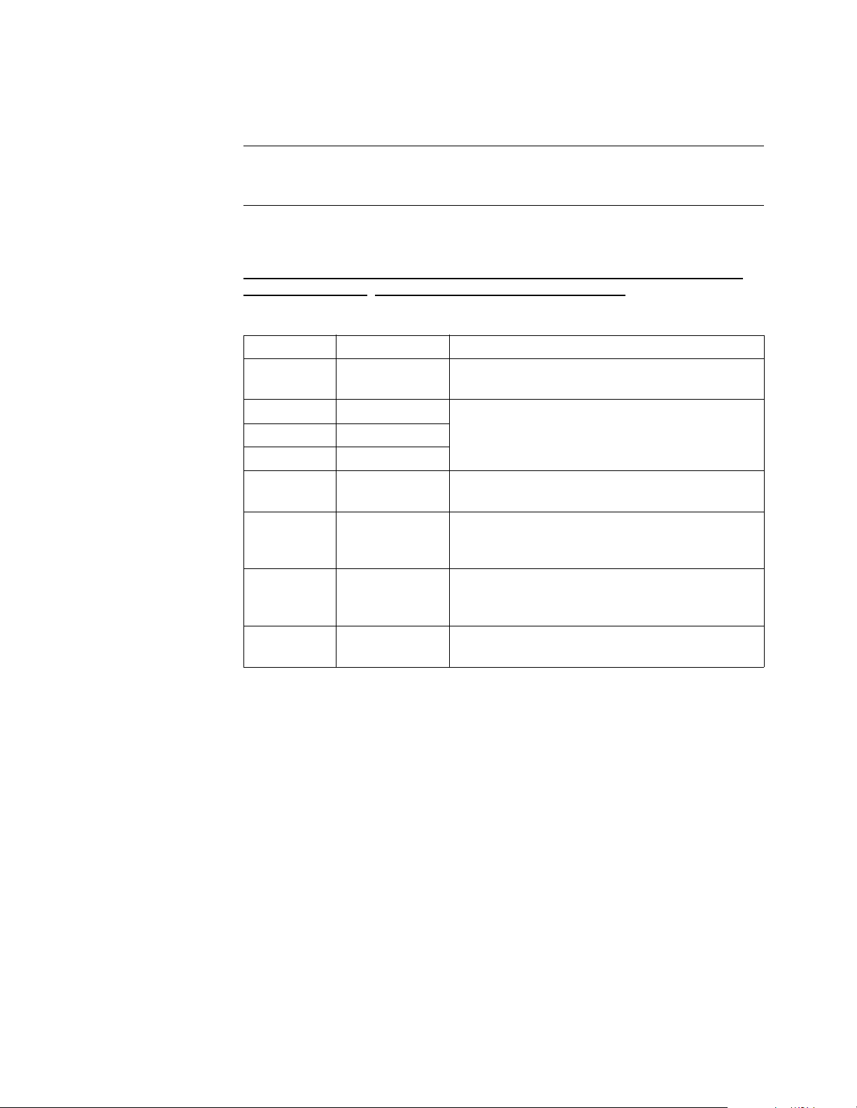
Front Panel Figure C-1 shows the front panel of the AL 200. The LEDs indicate connectivity
status and also act as a diagnostic aid. Refer to the “LEDs” section on page C-2.
Text and graphics on
ER
W
S1
PO
S2
S3
SG
D
D
M
R
T
PC
Figure C-1. Al 200 Front Panel
Back Panel Figure C-2 shows the back panel of the AL 200.
front-panel labe l may
vary with multimedia
vendor.
Coaxial Connector,
Type F
CABLE
Power Connector
POWER
RESET
Reset
Button
USB Connector
Figure C-2. AL 200 Back Panel
Ethernet LAN port
ENET ANTENNA
Reserved for
Motorola use
Antenna Connector
Front and Back Panels C-1
Page 34
LEDs
LEDs
Introduction The AL 200 front-panel LEDs offer diagnostic and connectivity status information.
This section lists the LED states.
LEDs This table describes the AL 200’s front-panel LEDs. For information on LED status
during modem states of ope rati on, ref er to t he Diagn ostic s sect io n in the Motorola io
cable modem DM 100 Installation Manual.
-->>>**this statemnt comes from the older PL 100 manual. COnfirm with Peg
Burbank or remove. Same for the same statement, next page.
Cable Modem LEDs
LED Name Indicates
Power Power Whether electrical power is applied to the
modem
S1 Status 1 The modem state (refer to the “S1, S2, and S3
S2 Status 2
LEDs” section on page C-3)
S3 Status 3
PC Personal
Computer
TRANSMIT Transmit Data That the multi-user modem is transmitting data
RECEIVE Receive Data That the multi-user modem is receiving data
MESSAGE Message The function of this LED is defined by the cable
Whether the cable modem is connected to
customer premise equipment (CPE)
(on the HPNA port, Ethernet port, or both) to a
computer or CPE on the home network
(on the HPNA port, Ethernet port, or both) from
a computer or CPE on the home network
system operator
C-2 Front and Back Panels
Page 35
LEDs
S1, S2, and S3
LEDs
This table describes the status LEDs for the AL 200 during initial power-up. For
information on changes in LEDs that indicate fail ur es or ot her prob lems, refer to the
Motorola io cable modem DM 100 Installation Manual.
S1, S2, and S3 LED Status
S1 LED S2 LED S3 LED State
Flashing Flashing Off Power-up testing
Flashing Flashing On Power-up failure
Flashing Flashing Flashin g Boot load failure
Flashing Off Off Scanning for downstream data channel
Flashing On Off Locked on downstream channel
Flashing On On Performing ranging function
Flashing Off On Obtaining upstream channel configuration
Off Flashing Off Establishing IP connectivity
On Flashing Off Establishing time of day
On Flashing On Transferring modem configuration from the
TFTP Server
Off Off Flashing Downloading software from the TFTP Server
On Off Flashing Registering
On On Flashing Establishing Baseline Privacy encryption
On Off Off Network access is disabled
Off On Off Changing upstream channel
On On Off Changing upstream channel with ranging
Off Off On Changing downstream channel
On O ff On Software download initia ted by SNMP
On On On Fully registered and operating normally
Front and Back Panels C-3
Page 36

Page 37

Appendix D
Regulatory Information
Regulatory
Marking
Product Safety
Regulatory
Marking
Type-approval labels indicate compliance with country regulations. AL 200s carry
country-specific labels to indicate compliance.
Canadian Emission Statements
AL 200: This Class B digital apparatus meets all requirements of the Canadian
Interference-Causing Equipment Regulations.
Cet appareil numé rique de la class e B respe cte tou tes les exigence s du Règl ement sur
le materiél brouilleur du Canada.
Regulatory labels in dic at e complian ce wit h saf et y st anda rds . AL 200s. Mod ems and
enclosures carry one of the following labels:
UL, CSA
Regulatory Information D-1
Page 38

D-2 Regulatory Information
Page 39

Glossary
10BaseT Unshielded, twisted pair cable with an RJ-45 connector used with an Ethernet
LAN. “10” indicates the speed: 10Mbps; “Base” means that it is baseband
technology; and “T” means that it is a twisted pair cable.
16 QAM Modulation scheme used by a modem transmitter. QAM uses amplitude and
phase modulation to encode multi ple bits of da ta in one signa ling element, thus
achieving higher data transfe r rates than ampl it ude or phas e mod ula ti on al one.
16 QAM encodes four bits per symbol as one of sixteen amplitude and phase
combinations. 16 QAM refers to th e number of disc rete pha se/ampl itude states
that represent data bi ts.
64 QAM A modulation scheme used by a cable modem receiver. 64 QAM uses
amplitude and phase modulation to encode multiple bits of data in one
signaling element. 64 QAM encodes 6 bits per symbol as one of 64 amplitude
and phase combinations.
256 QAM A modulation scheme used by a cable modem receiver. 256 QAM uses
amplitude and phase modulation to encode multiple bits of data in one
signaling element. 256 QAM encod es 8 bits per symbol as one of 256 pos si bl e
amplitude and phase combinations.
bandwidth The range of frequencies that can be passed over a channel.
bridge A device used to connect two LANs that use similar LAN protocols. The
bridge acts as an address filter, picking up packets from one LAN that are
intended for a destination on another LAN and passing them on. The bridge
does not modify the contents of a packet and does not add anything to the
packet. The bridge operates at Layer 2 of the Open System Interconnect (OSI)
model.
broadband Network technology that multiplexes multiple, independent network carriers
onto a single cabl e. The technology is us ed to c arr y voice, video, a nd dat a ove r
a cable.
broadcast Transmissi on to two or more devices at the same t ime, such as over net work or
by satellite; protocol mechanism by which group and universal addressing is
supported.
Cable Modem
Termination System
(CMTS)
coaxial cable (coax) Cable that consists of an inner conductor surrounded by insulation. An outer
A device located in the cable system headend that interfaces the hybrid
fiber/coaxial (HFC) network to local or remote Internet Protocol (IP) networks.
Motorola’s CMTS (Cable Router) provides connections between IP hosts and
cable modems, and between the cable modems and the connected subscribers.
It also manages cable modem bandwidth.
conductor is wrapped around the insulation, which is typically covered by
plastic. Coaxial cable has large bandwidth and can support transmission over
long distances.
Glossary-1
Page 40

communication network A facility that provides a data transf er servi ce among the equipment attached to
a network.
Customer Premise
Equipment (CPE)
Equipment at the end user premises. This equipment may be provided by the
end user or service provider.
DOCSIS The Data-Over-Cable S ervice Inter face Specifications.
downstream The direction of data flow from a CMTS to a cable modem.
Dynamic Host
Configuration Protocol
(DHCP)
A protocol that allows dynamic ass ignment of IP add resses to other computers.
DHCP is also used to assign IP addresses to cable modems. This protocol can
also provide other parameters such as a TFTP server address and TFTP path
and filename.
encryption A method of encoding data.
encryption key A key that is used to encrypt data to deter unauthorized interception.
Ethernet A networking standard running at speeds of 10 Mbps (10BaseT) or 100 Mbps
(100BaseT).
Ethernet address The physical address of the Ethernet port. It is also kno wn as a MAC a ddress o r
a NIC address.
Ethernet card A card that resides in an expansion slot of a PC. It can be a built-in Ethernet
port or an Ethernet port with a 10BaseT adapter. The Ethernet card takes data
from the computer, converts it to serial data, puts it into a packet format, and
sends it over the 10BaseT or 100BaseT LAN.
The Ethernet card has a 48-bi t a ddr ess bur ned i nt o the ROM. It is also refer red
to as a Net work Interface Card (NIC).
event A message generated by a cable modem to inform an operator that something
has occurred.
F connector Connector on a cable modem that connects it to the cable system.
File Transfer Protocol
(FTP)
A protocol that allows users to log into a remote system, identify them selves,
list remote directories, and copy files to and from the remote machine. FTP
understands a few basic file formats. It is more complex than Telnet in that it
maintains separate TCP connections for control and data transfer.
firewall A method of preventin g a n etwork from unautho rized acce ss by filteri ng acces s
packets. This is done by the software on a cable modem or a dedicated server.
Forward Error
Correction (FEC)
A technique for correcting errors incurred in transmission over a
communications channel by the receiver, without requiring the retransmission
of information by the transmitter; typically it involves a convolution of the
transmitted bits and the appending of extra bits, using a common algorithm by
the receiver and transmitter.
headend The central office of the service provider where cable signals originate.
Home Phone Networking
Alliance (HPNA)
Industry organization that defines a set of standards for home phoneline
networking technologies (www.homephna.org).
Glossary-2
Page 41

hub A device used to connect multiple devices to a LAN or similar structure to a
headend.
Hybrid Fiber/Coaxial
(HFC) network
A network where the trunk of the cable plant is fiber technology. The fiber is
connected to a coaxial cable and the signal is converted so that it is compatible
to that media. The coaxial cable runs through the branches of the network and
is dropped into the subscriber’s home.
Initial Maintenance (IM) A contention interval that provides an opportunity for modems to join a
network.
Internet A collection of interc onnect ed networ ks used for wor ld-wid e communica tions .
These networks use the TCP/IP protocol.
IP address A 32-bit address assigned to every device in a network. An IP address has two
parts: a network address and a host address. Each network is assigned an
address by a governing agency, and each company administrator assigns an
address to each host. Network addresses can be 8, 16, or 24 bits long
corresponding to classes A, B, and C, respectively, with the host address
occupying the remainder of the 32 bits. If a service provider uses Class C
addresses, for example, the first 24 bits are the network address and 8 bits are
used for host addresses.
An IP network address can be further divided by using classless addressing or
subnetting. See subnet.
IP filtering IP filtering allows IP pack ets to be dropped according to information in the
packet, such as its source or destination address. IP filtering can prevent
subscribers from accessing headend servers, enforce subscribers to log on to
the cable network, enforce separately-billed service packages for data, and
provide group access control for IP Multicast.
IP network A group of IP routers that route IP datagrams. These routers are sometimes
referred to as interne t gateways. Singl e users acces s the IP network f rom a host.
Each individual network in the Internet includes some combination of hosts
and IP routers.
Local Area Network
(LAN)
A privately owned and administe red network for dat a communications. A LAN
provides a relatively high bandwidth over a limited geographical area for
communication among the attached devices, typically personal computers and
servers. Communication is usually accomplished by broadcasting on a
connectionless basis over a shared me dia .
MAC Layer Domain A collection of upstream and downstream channels for which a single Media
Access Control (MAC) Allocation and Management Protocol operates. Its
attachments include one CMTS and a number of cable modems.
Maximum Transmission
Unit (MTU)
The largest amo unt of data that can be tran smitte d in o ne dis crete messag e on a
physical network. MTUs can be user configurable.
Mbps Mega (million) bits per second. A rate of data transfer.
Glossary-3
Page 42

Media Access Control
Address (MAC)
The hardware address usual ly “bur ned in” on a ROM for an y devic e connec ted
to the network. Ethernet cards in the subscriber PC have a MAC address. The
cable modem and the network interfa ce card on a CMTS have MAC add resses.
The MAC address is used by the link layer protocol to forward packets “one
hop at a time” between th e host and the first router and between t he first router
and the next router and so on t hr ough the network until t he packet arrives at i ts
final destination. In contrast, an IP address is a “source” to “destination”
address. It does not include all the intermediate hops.
Media Access Control
(MAC) sublayer
The part of the data link layer that supports topology-dependent functions and
uses the services of the physical layer to provide services to the logical link
control (LLC) sublayer.
MHz Mega Hertz. A measure of radio frequency - millions of cycles per second.
modem registration The process by which a cable modem makes itself known to a CMTS. The
modem configuration and au thori zati on are veri fied and the COS is n egoti ated.
network driver A file packaged with the Ethernet card that connects the card to the PC
communications software.
network layer Layer 3 in the O pen System Interconnection (OSI) architecture. This layer
provides services to establish a path between open systems.
packet data Each IP datagram consists of one or more packets. A packet has a header that
contains the source address and a destination address for routing (and other
housekeeping informatio n). Since b oth th e he ader and t he data are a can va ry in
length, an IP datagram itself is variable in length.
PING A program that tests host reachability by using the Internet Control Message
Protocol (ICMP) echo request and waiting for a reply. It is initiated and
verified from an IP device.
physical layer (PHY) Layer 1 in the Open System Interconnection (OSI) a rchitecture. It is the layer
that provides services t o trans mit bit s or group s of bits over a tr ansmiss ion li nk
between open systems. It includes the electrical, mechanical, and handshaking
procedures.
Physical Media
Dependent (PMD)
Sublayer
A sublayer of the physical layer that transmits bits or groups of bits over
particular types of transmission links between open systems. It entails the
electrical, mechanical, and handshaking procedures.
piggybacking A process that occurs when a modem transmits data and requests additional
bandwidth at the same time.
Quadrature Amplitude
Modulation (QAM)
Modulation scheme that uses both amplitude and phase modulation to encode
multiple bits of data in one signaling element, thus achieving higher data
transfer rates than just amplitude or phase modulation alone.
However, the signal is more prone to errors caused by noise and so requires a
better quality transmissi on circuit th an QPSK (lower noise an d therefore higher
Carrier to Noise Ratio (CNR) value).
Glossary-4
Page 43

Quadrature Phase Shift
Key (QPSK)
Modulation that sends two bits of information per symbol period with one bit
90 degrees out of phase with the other bit being sent. There are only four
constellation point s. These point s represen t the fou r combinat ions that can take
place and are represented by the coordinates:
(0,0 - 0,1 - 1,0 - 1,1).
DQPSK modulation states that the information bits are differentially encoded
prior to being modulated.
quality of service The accumulation of the cell loss, delay, and delay variation incurred by cells
belonging to a connection.
radio frequency (RF) Signals that are used by a cable modem transmitter and receiver to send data
over the HFC network. A radio frequency carrier is modulated to encode the
digital data stream for transmission across the cable network.
return loss A measurement of the quality of the match of the device to the cable system.
Return loss is the ratio of the amount of power reflected by the device.
RJ-45 An 8-pin modular connector on a Motorola cable modem or CMTS that
connects the modem to a PC or external hub. Used as a 10BaseT or 100BaseT
standard connector.
router A device used to connect two subnetworks at the network layer. These
subnetworks may be similar. An internet protocol is used in each router and in
each host of the network. A router operates at Layer 3 of the OSI model.
service p rovider A company providing cable data services to subscribers.
splitter A piece of coax equipment that divides a single spectrum into multiple
identical spectrums.
TCP/IP A set of protocols that provides the standards and rules for controlling and
managing communications between networks. TCP/IP has become the
worldwide standard for internetworking and is the basis for the worldwide
Internet. TCP/IP stands for Transmission Control Protocol/Internet Protocol.
There are related protocols, services, and applications that are part of the
TCP/IP protocol suite.
TCP/IP Communications
Stack
Software in the subscriber PC that processes packets through the
communication layers. The TCP/IP communication stack handles the
communications between the subscr iber’ s appli cati on, for example, an I nter net
browser, and servers on the Internet.
Transmission Control
Protocol (TCP)
A reliable transport proto col of the I nterne t sui te. TCP i s a con necti on-ori ented
protocol that uses IP to transmit the data across the ne twork. TCP is an
end-to-end protocol defining the rules and procedures for exchanging
informatio n between communicating p artners (hosts). Transmission Control
Protocol resides in the Transport Layer of the OSI stack. It works on top of
connectionless Network Layer IP. TCP segments messages into datagrams,
uses a timer to keep track of outstanding datagrams, retransmits datagrams if
requested, and performs error checking on incoming dat agrams.
Universal Serial Bus
(USB)
A device that allows PCs to connec t t o per ip her als, eliminating the need for an
Ethernet Card.
Glossary-5
Page 44

upstream The direction of data flow from a cable modem subscriber to a CMTS.
World Wi de Web An interface to the Internet. You use the World Wide Web to navigate and
hyperlink to other information on the Internet.
Glossary-6
Page 45

A
access setting
B
back panel
C
cable connector
cable subscriber
caution
disconnected
modem connection and disconnection
operation with object on top of cable modem
power supply
caution description
CD-ROM
CISPR
components
connecting multiple PCs to modem
connections
connectors
async
cable
PHONE (HPNA)
D-1
CSA
1-12
A-2, C-1
B-1
1-13
1-7
1-7
v
1-12
D-1
1-2
B-3
C-1
B-1
B-1
B-2
1-7
1-7
D
data application
diagnostic information
disconnecting a cable modem
driver, network
E
ENET connector
ENET port
environmental specifications
Ethernet
Ethernet cable
connecting
Ethernet connections
F
D-1
FCC
front panel
H
HPNA (PHONE) connector
I
installation
requirements
tasks
installing net manager software
1-5, 1-6
C-2
1-5, 1-6
B-1
B-3
A-2
1-6
1-10
1-10
C-1
B-2
1-4
1-4
1-7
1-12
Page 46

L
LED states
LEDs
M
MESSAGE LED
multi-user modem
N
net manager software
network driv er
O
on-line Help
P
PC LED
PCMCIA
PHONE (HPNA) connector
physical specifications
pinouts
power specifications
C-2
A-2, C-1
C-2
front and back panels
installing
1-12
C-1
1-5, 1-6
1-13
C-2
1-5
B-2
A-2
ENET port
modem to customer premise router
modem to hub
modem to PC
power connector
B-1
B-3
B-3
B-2
A-3
B-4
R
RECEIVE LED
regulatory specifications
requirements
resource
S
S1, S2, S3 LEDs
safety notices
safety standards
specifications
IP and MAC layer
modulation mode physical
physical layer
physical/environmental
power
regulatory/power
subscriber
T
TCP/IP network protocol
temperature
TRANSMIT LED
C-2
1-4
1-12
C-2
vi
D-1
A-1
A-1
A-1
A-3
A-3
1-13
A-2
C-2
A-3
A-1
A-2
1-5, 1-6
Page 47

troubleshooting 1-13
D-1
TUV
U
D-1
UL
USB cable
connecting
USB port
W
warning
service
warning description
Windows
Wireless HomeRF PCMCIA adapter
Wireless HomeRF USB adapter
1-10
1-5
1-2
v
1-5, 1-6
1-5
1-5
 Loading...