

Page 1
RDX™ Series
Two-way Radios
User Guide
en-US fr-CA
RDU4160d & RDU4163d Display Model
Page 2

Open Source Software Legal Notices:
This Motorola Solutions product contains Open Source Software. For information
regarding licenses, acknowledgements, required copyright notices and other usage
terms, refer to the documentation for this Motorola Solutions product at:
http://businessonline.motorolasolutions.com
Go to: Resource Center > Product Information > Manual > Accessories.
Informations juridiques relatives aux logiciels libres :
Ce produit Motorola Solutions contient des logiciels libres. Pour obtenir des renseignements relatifs aux licences, aux attestations, aux avis de droits d'auteur requis et
à d'autres conditions d'utilisation, reportez-vous à la documentation concernant ce
produit Motorola Solutions à l'adresse suivante :
http://businessonline.motorolasolutions.com
Allez à l'adresse Resource Center > Product Information > Manual > Accessories.
Page 3

English
CONTENTS
Contents. . . . . . . . . . . . . . . . . . . . . . . . . . . . .1
Product Safety. . . . . . . . . . . . . . . . . . . . . . . .5
Introduction . . . . . . . . . . . . . . . . . . . . . . . . . .6
Package Contents. . . . . . . . . . . . . . . . . . . . . .6
FCC Licensing Information . . . . . . . . . . . . .7
Interference Information . . . . . . . . . . . . . . . . .7
Canada Licensing Information. . . . . . . . . . .9
General Information. . . . . . . . . . . . . . . . . . . . .9
The License Application . . . . . . . . . . . . . . . . .9
Batteries and Chargers Safety Information .
10
Operational Safety Guidelines. . . . . . . . . . . .11
Radio Overview . . . . . . . . . . . . . . . . . . . . . .12
Parts Of The Radio . . . . . . . . . . . . . . . . . . . .12
On/Off/Volume Knob. . . . . . . . . . . . . . . .13
Channel Selector Knob. . . . . . . . . . . . . .13
Accessory Connector . . . . . . . . . . . . . . .13
Model Label . . . . . . . . . . . . . . . . . . . . . .13
Microphone . . . . . . . . . . . . . . . . . . . . . . .13
Antenna. . . . . . . . . . . . . . . . . . . . . . . . . .13
LED Indicator . . . . . . . . . . . . . . . . . . . . .13
Front Buttons . . . . . . . . . . . . . . . . . . . . . 13
Side Buttons. . . . . . . . . . . . . . . . . . . . . . . . . 14
The Lithium-Ion (Li-Ion) Battery . . . . . . . 14
Battery Features. . . . . . . . . . . . . . . . . . . . . . 15
About the Li-Ion Battery . . . . . . . . . . . . . 15
Battery Recycling and Disposal . . . . . . . 16
Installing the Lithium-Ion (Li-Ion)
Battery . . . . . . . . . . . . . . . . . . . . . . . . 17
Removing the Lithium-Ion (Li-Ion)
Battery . . . . . . . . . . . . . . . . . . . . . . . . 17
Attaching the Antenna . . . . . . . . . . . . . . 18
Removing the Antenna . . . . . . . . . . . . . 18
Installing Spring Action Belt clip. . . . . . . 19
Power Supply, Adaptor and Drop-in Tray
Charger . . . . . . . . . . . . . . . . . . . . . . . 19
Battery Life Information . . . . . . . . . . . . . 20
Charging the Battery . . . . . . . . . . . . . . . 21
Drop-in Tray Charger LED Indicators . . 23
Estimated Charging Time . . . . . . . . . . . 25
Multi-Unit Charger LED Indicators . . . . . 27
Getting Started . . . . . . . . . . . . . . . . . . . . . . 28
Turning radio ON/OFF . . . . . . . . . . . . . . . . . 28
Adjusting Volume . . . . . . . . . . . . . . . . . . . . . 28
CONTENTS
1
Page 4

English
READING THE DISPLAY . . . . . . . . . . . . . . .28
Selecting a Channel . . . . . . . . . . . . . . . . . . .28
Talking and Monitoring . . . . . . . . . . . . . . . . .29
Receiving a Call . . . . . . . . . . . . . . . . . . . . . .29
Signal strength indicator and channel busy
indicators . . . . . . . . . . . . . . . . . . . . . . . . . .29
Talk Range . . . . . . . . . . . . . . . . . . . . . . . . . .30
Radio LED Indicators . . . . . . . . . . . . . . . . . .31
Hands-Free Use/VOX . . . . . . . . . . . . . . . . . .32
With Compatible VOX Accessories. . . . .32
CONTENTS
Hands Free without Accessories (iVOX).32
Toggle Voice Prompt in User Mode . . . . . . .33
Power Up - Tone Mode . . . . . . . . . . . . . . . . .33
Reset to Factory Defaults . . . . . . . . . . . . . . .33
Keypad Beeps. . . . . . . . . . . . . . . . . . . . . . . .33
Keypad Lock/Unlock . . . . . . . . . . . . . . . . . . .33
Menu Options . . . . . . . . . . . . . . . . . . . . . . . .34
Setting VOX/IVOX Sensitivity . . . . . . . . . . . .34
Microphone Gain. . . . . . . . . . . . . . . . . . . . . .35
Programming Features . . . . . . . . . . . . . . . .36
Advanced Configuration Mode . . . . . . . . . . .36
Entering Advanced Configuration Mode .36
Programming RX (Reception) Frequencies .37
Programming RX (Reception) codes (CTCSS/
DPL) . . . . . . . . . . . . . . . . . . . . . . . . . . . . . 37
Programming Scramble . . . . . . . . . . . . . . . . 38
Programming Maximum Number of
Channels . . . . . . . . . . . . . . . . . . . . . . . . . . 38
Programming Call Tones . . . . . . . . . . . . . . . 39
Programming Microphone Gain Level . . . . . 39
Programming Microphone Accessory Gain
Level . . . . . . . . . . . . . . . . . . . . . . . . . . . . . 40
Other Programming Features . . . . . . . . . . . 41
Scan. . . . . . . . . . . . . . . . . . . . . . . . . . . . 41
Programming Scan List . . . . . . . . . . . . . 41
Programming Weather Channel (Not
allowed on RDX4163) . . . . . . . . . . . . 42
Editing Channel Alias Name . . . . . . . . . 42
Nuisance Channel Delete . . . . . . . . . . . 43
Customer Programming Software (CPS) . . . 44
Time-Out Timer . . . . . . . . . . . . . . . . . . . 44
Power Select . . . . . . . . . . . . . . . . . . . . . 44
Call Tones . . . . . . . . . . . . . . . . . . . . . . . 45
Scramble . . . . . . . . . . . . . . . . . . . . . . . . 45
Reverse Burst . . . . . . . . . . . . . . . . . . . . 45
Text-to-Speech (Changing Pre-Defined Voice
2
Page 5

English
Aliases). . . . . . . . . . . . . . . . . . . . . . . . . . . .45
Enable User Pre-Defined Voice Prompt
(VP) Checkbox . . . . . . . . . . . . . . . . . .45
User Pre-Defined Voice Prompt (VP) Text .
45
Import Voice File. . . . . . . . . . . . . . . . . . .45
Listen to User Customized Voice Prompt
(VP) Text. . . . . . . . . . . . . . . . . . . . . . .46
Weather Feature (Not for RDU4163) . . . . . .46
Weather Alert Mode . . . . . . . . . . . . . . . .47
Weather Channel Frequencies Table . . .47
The Weather Alert has two modes of operations
47
EOM Enabled . . . . . . . . . . . . . . . . . . . . .48
New Alert Tone Timer. . . . . . . . . . . . . . .48
Event Type Filter . . . . . . . . . . . . . . . . . . . . . .48
All Events . . . . . . . . . . . . . . . . . . . . . . . .49
Alert Test Event . . . . . . . . . . . . . . . . . . .49
Warning. . . . . . . . . . . . . . . . . . . . . . . . . . . . .49
Watch . . . . . . . . . . . . . . . . . . . . . . . . . . . . . .49
Emergency . . . . . . . . . . . . . . . . . . . . . . . . . .49
Statement . . . . . . . . . . . . . . . . . . . . . . . . . . .50
Event Code Filter. . . . . . . . . . . . . . . . . . . . . .50
Block Event . . . . . . . . . . . . . . . . . . . . . . . . . 50
Event Code . . . . . . . . . . . . . . . . . . . . . . . . . 50
The Critical Events Table . . . . . . . . . . . . . . . 50
Geographic Filter . . . . . . . . . . . . . . . . . . . . . 52
State. . . . . . . . . . . . . . . . . . . . . . . . . . . . . . . 52
County . . . . . . . . . . . . . . . . . . . . . . . . . . . . . 52
FIPS . . . . . . . . . . . . . . . . . . . . . . . . . . . . . . . 53
Cloning Radios. . . . . . . . . . . . . . . . . . . . . . . 53
Cloning with a Multi Unit Charger
(MUC) . . . . . . . . . . . . . . . . . . . . . . . . 53
Cloning Radio using the Radio to Radio
(R2R) Cloning Cable (Optional
Accessory) . . . . . . . . . . . . . . . . . . . . . 54
Cloning using the Customer Programming
Software (CPS) . . . . . . . . . . . . . . . . . 57
Troubleshooting. . . . . . . . . . . . . . . . . . . . . 58
Use and Care . . . . . . . . . . . . . . . . . . . . . . . 62
Frequency and Code Charts . . . . . . . . . . . 63
RDX UHF Frequencies Chart. . . . . . . . . . . . 63
RDU4163 – UHF Default Frequencies
Chart . . . . . . . . . . . . . . . . . . . . . . . . . . . . . 63
RDX UHF Frequencies Chart. . . . . . . . . . . . 65
RDU4160 – UHF Default Frequencies
CONTENTS
3
Page 6

English
Chart. . . . . . . . . . . . . . . . . . . . . . . . . . . . . .68
Programming Customized Frequencies On
RDU4160 . . . . . . . . . . . . . . . . . . . . . . . . . .69
CTCSS and PL/DPL Codes . . . . . . . . . . . . .70
Accessories . . . . . . . . . . . . . . . . . . . . . . . . .75
Antenna. . . . . . . . . . . . . . . . . . . . . . . . . . . . .75
Audio Accessories. . . . . . . . . . . . . . . . . . . . .75
Battery. . . . . . . . . . . . . . . . . . . . . . . . . . . . . .75
Cables . . . . . . . . . . . . . . . . . . . . . . . . . . . . . .75
Chargers . . . . . . . . . . . . . . . . . . . . . . . . . . . .76
Carry Accessories . . . . . . . . . . . . . . . . . . . . .76
CONTENTS
Software Applications . . . . . . . . . . . . . . . . . .76
Power supplies ac pin adapters . . . . . . . . . .76
Power supplies . . . . . . . . . . . . . . . . . . . . . . .76
Motorola Solutions Limited Warranty for the
United States and Canada . . . . . . . . . . . . .77
4
Page 7

English
PRODUCT SAFETY
!
C a u t i o n
PRODUCT SAFETY AND RF
EXPOSURE COMPLIANCE
Before using this product,
read the operating
instructions and RF energy
awareness information
contained in the Product
Safety and RF Exposure
booklet enclosed with your
radio.
ATTENTION!
This radio is restricted to occupational use only
to satisfy FCC RF energy exposure
requirements.
For a list of Motorola Solutions-approved
antennas, batteries and other accessories, visit
the following website which lists approved
accessories:
www.motorolasolutions.com/RDX
PRODUCT SAFETY
5
Page 8

English
INTRODUCTION
Thank you for purchasing the Motorola Solutions®
RDX Series™ Radio. This radio is a product of
Motorola Solutions' 80 plus years of experience as a
world leader in the designing and manufacturing of
communications equipment. The RDX Series radios
provide cost-effective communications for businesses
such as retail stores, restaurants, schools,
construction sites, manufacturing, property and hotel
management and more. Motorola Solutions
professional two-way radios are the perfect
communications solution for all of today's fast-paced
industries.
INTRODUCTION
Note: Read this user guide carefully to ensure you
know how to properly operate the radio
before use
PACKAGE CONTENTS
• Radio
• Antenna
• Lithium-Ion Battery
• Belt Clip
• Power Supply
• Quick Reference Guide
• Drop-in Tray Charger
• Product Safety & RF Exposure Booklet
For a copy of a large-print version of this user
guide or for product-related questions, contact
1-800-448-6686 in the USA
1-800-461-4575 in Canada
1-888-390-6456 on TTY (Text Telephone)
For product related information, visit us at:
www.motorolasolutions.com/RDX
Or
Business Radios
RPSD 1C15, Motorola
8000 West Sunrise Boulevard
Plantation, Florida 33322
6
Page 9

English
FCC LICENSING INFORMATION
INTERFERENCE INFORMATION
This device complies with Part 15 of the FCC
Rules. Operation is subject to the condition that
this device does not cause harmful
interference.
RDX Series Business two-way radios operate
on radio frequencies that are regulated by the
Federal Communications Commission (FCC).
To transmit on these frequencies, you are
required to have a license issued by the FCC.
Application is made available on FCC Form
601 and Schedules D, H, and Remittance Form
159.
To obtain these FCC forms, request document
000601 which includes all forms and
instructions. If you wish to have the document
faxed, mailed or have questions, use the
following contact information.
FCC LICENSING
INFORMATION
Faxed contact the
Fax-On- Demand
system at:
1-202-418-0177 1-800-418-FORM
7
Mailed call the FCC forms hotline at:
1-800-418-3676
Questions regarding FCC
license contact the FCC at:
1-888-CALL-FCC
1-888-225-5322
Or: http://www.fcc.gov
Page 10

English
Before filling out your application, you must
decide which frequency(ies) you can operate
on. See “Frequencies and Code Charts”. For
questions on determining the radio frequency,
call Motorola Solutions Product Services at:
1-800-448-6686
Changes or modifications not expressly
approved by Motorola Solutions may void the
INFORMATION
FCC LICENSING
user’s authority granted by the FCC to operate
this radio and should not be made. To comply
with FCC requirements, transmitter
adjustments should be made only by or under
the supervision of a person certified as
technically qualified to perform transmitter
maintenance and repairs in the private land
mobile and fixed services as certified by an
organization representative of the user of those
services.
Replacement of any transmitter component
(crystal, semiconductor and more.) not
authorized by the FCC equipment authorization
for this radio could violate FCC rules.
Use of this radio outside the country where it
was intended to be distributed is subject to
government regulations and may be prohibited.
8
Page 11

English
CANADA LICENSING INFORMATION
GENERAL INFORMATION
The operation of your Motorola Solutions radio is
subject to the Radiocommunications Act and must
comply with rules and regulations of the Federal
Government’s department of Industry Canada.
Industry Canada requires that all operators using
Private Land Mobile frequencies obtain a radio license
before operating their equipment.
An application for your Industry Canada license is
made on the form included with your radio. Additional
forms and latest license application versions can be
obtained from the nearest Industry Canada District
office. A list of these offices is included for your
information.
This device complies with Industry Canada’s licenceexempt RSSs. Operation is subject to the following
two conditions:
1. This device may not cause interference; and
2. This device must accept any interference,
including interference that may cause undesired
operation of the device.
THE LICENSE APPLICATION
General Instructions
1. Fill in the items as per the instructions. If you
need additional space for any item use the
reverse side of the application.
2. Be sure to use a typewriter or print legibly.
3. Make a copy for your files.
4. Prepare a cheque or money order made out to
the “Receiver General for Canada”, for an
amount, which is on the following schedule, for
each radio purchased. (License is valid until
April 1st of each year, and the renewed.
5. Mail your completed application, along with your
cheque or money order to the closest Industry
Canada District office, according to the list on
pages.
To obtain the latest Canadian License Application
form, please go to:
www.ic.gc.ca
CANADA LICENSING
INFORMATION
9
Page 12

English
BATTERIES AND CHARGERS SAFETY INFORMATION
This document contains important safety and
operating instructions. Read these instructions
carefully and save them for future reference.
Before using the battery charger, read all the
instructions and cautionary markings on
• the charger,
• the battery, and
• the radio using the battery
SAFETY INFORMATION
1. To reduce risk of injury, charge only the
BATTERIES AND CHARGERS
rechargeable Motorola Solutions-authorized
batteries. Other batteries may explode, causing
personal injury and damage.
2. Use of accessories not recommended by
Motorola Solutions may result in risk of fire,
electric shock, or injury.
3. To reduce risk of damage to the electric plug
and cord, pull by the plug rather than the cord
when disconnecting the charger.
4. An extension cord should not be used unless
absolutely necessary. Use of an improper
extension cord could result in risk of fire and
electric shock. If an extension cord must be
used, make sure that the cord size is 18AWG
for lengths up to 100 ft (30.48 m), and 16AWG
for lengths up to 150 ft (45.72 m).
5. To reduce risk of fire, electric shock, or injury, do
not operate the charger if it has been broken or
damaged in any way. Take it to a qualified
Motorola service representative.
6. Do not disassemble the charger; it is not
repairable and replacement parts are not
available. Disassembly of the charger may
result in risk of electrical shock or fire.
7. To reduce risk of electric shock, unplug the
charger from the AC outlet before attempting
any maintenance or cleaning
10
Page 13

English
OPERATIONAL SAFETY GUIDELINES
• Turn the radio OFF when charging battery.
• The charger is not suitable for outdoor use. Use
only in dry locations/conditions.
• Connect charger only to an appropriately fused
and wired supply of the correct voltage (as
specified on the product).
• Disconnect charger from line voltage by removing
main plug.
• The outlet to which this equipment is connected
should be nearby and easily accessible.
• In equipment using fuses, replacements must
comply with the type and rating specified in the
equipment instructions.
• Maximum ambient temperature around the power
supply equipment must not exceed 40 °C (104
°F).
• Power output from the power supply unit must not
exceed the ratings stated on the product label
located at the bottom of the charger.
• Make sure that the cord is located where it will
not be stepped on, tripped over, or subjected to
water, damage, or stress.
BATTERIES AND CHARGERS
SAFETY INFORMATION
11
Page 14
English
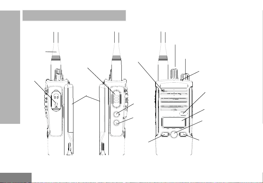
Antenna
On/Off/Volume
Knob
LED
Indicator
Channel Selector
Knob
Audio
Accessory
2 Pin
Connector
PTT (Push-ToTalk) Button
Battery
Microphone
SB1
SB2
Programmable
Button A
Programmable
Button A
Menu Button
Display
Model Label
RADIO OVERVIEW
RADIO OVERVIEW
PARTS OF THE RADIO
12
Page 15
English
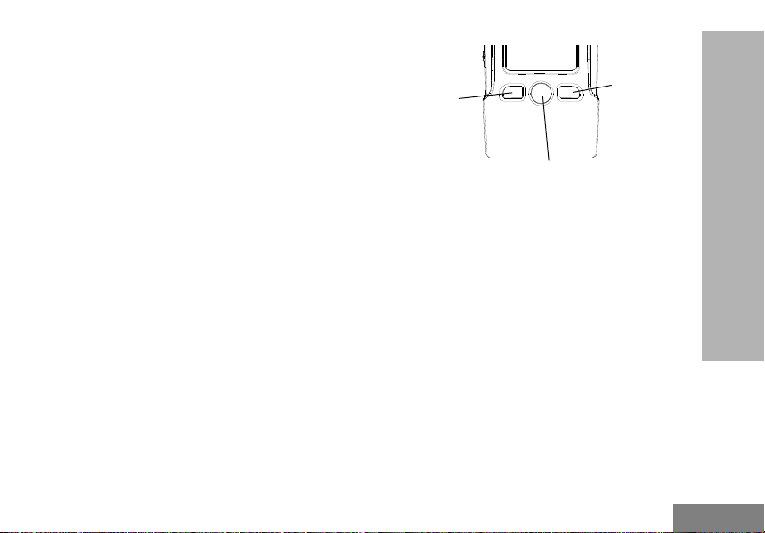
On/Off/Volume Knob
Programmable
Button A
Programmable
Button A
Menu Button
Used to turn the radio ON or OFF and to adjust
the radio’s volume.
Channel Selector Knob
Used to switch the radio to different channels.
Accessory Connector
Used to connect compatible audio accessories.
Model Label
Indicates the model of the radio.
Microphone
Speak clearly into the microphone when
sending a message.
Antenna
For models RDX4160 and RDX4163 the
antennas are removable.
LED Indicator
Used to give battery status, power-up status,
radio call information and scan status.
Front Buttons
RADIO OVERVIEW
Menu Button
• Gives access to set up features like VOX/iVOX
levels, etc. It also allows you to move through all
the features while in Programming Mode. Default
set to preset Channel 1.
Programmable Button A
• Allows you to choose level or toggle options for
features the Menu is on. Default set to generate
current programmed call tone.
Programmable Button B
• Allows you to choose level or toggle options for
features the Menu is on. Default set to Backlight
Mode.
Note: A short press of either Programmable
Button (A or B) tunes the radio to the preset
13
Page 16

English
channel and the radio will play a good chirp.
You can assign different functions to these
buttons via the CPS. For example: Backlight
Time Out, Reverse Burst, Scan/Nuisance
Channel Delete, Monitor and Call Tones. To
learn more about how to program these
buttons, refer to “Advanced Configuration
Mode” on page 36 and “Customer
Programming Software (CPS)” on page 44.
SIDE BUTTONS
Push-to-Talk (PTT) Button
• Press and hold down this button to talk, release it
RADIO OVERVIEW
to listen.
Side Button 1 (SB1)
• The Side Button 1 is a general button that can be
configured by the Customer Programming
Software - CPS. The default setting of SB1 is
‘Monitor’.
Side Button 2 (SB2)
• The Side Button 2 is a general button that can be
configured by the CPS. The SB2 default setting is
‘Scan/Nuisance Channel Delete’.
The Lithium-Ion (Li-Ion) Battery
RDX Series comes with a Standard Capacity
Li-Ion battery. Other batteries may be available.
For more information, see “Battery Features”
on page 15.
This User Guide covers multiple RDX Series
models, and may detail some features your
radio does not have. The radio’s model is
shown on the bottom of the radio and provides
the following information:
14
Page 17
English
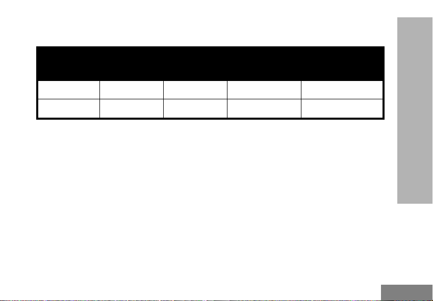
Table 1: RDX Series Radio Specifications
Model
RDU4160 UHF 4 16 Removable
RDU4163 UHF 4 16 Removable
BATTERY FEATURES
RDX Series radios provide Lithium-Ion
batteries that come in different capacities that
defines the battery life.
About the Li-Ion Battery
The RDX Series radio comes equipped with a
rechargeable Li-Ion battery. This battery should
be fully charged before initial use to ensure
optimum capacity and performance.
Battery life is determined by several factors.
Among the more critical are the regular
15
Frequency
Band
Transmit
Power (W)
Number of
Channels
overcharge of batteries and the average depth
of discharge with each cycle. Typically, the
greater the overcharge and the deeper the
average discharge, the fewer cycles a battery
will last. For example, a battery which is
overcharged and discharged 100% several
times a day, lasts fewer cycles than a battery
that receives less of an overcharge and is
discharged to 50% per day. Further, a battery
which receives minimal overcharging and
averages only 25% discharge, lasts even
longer.
Antenna
RADIO OVERVIEW
Page 18

English
Motorola Solutions batteries are designed
specifically to be used with a Motorola
Solutions charger and vice versa. Charging in
non-Motorola Solutions equipment may lead to
battery damage and void the battery warranty.
The battery should be at about 77 °F (25 °C)
(room temperature), whenever possible.
Charging a cold battery (below 50 °F [10 °C])
may result in leakage of electrolyte and
ultimately in failure of the battery. Charging a
hot battery (above 95 °F [35 °C]) results in
reduced discharge capacity, affecting the
performance of the radio. Motorola Solutions
RADIO OVERVIEW
rapid-rate battery chargers contain a
temperature-sensing circuit to ensure that
batteries are charged within the temperature
limits stated above.
Battery Recycling and Disposal
Li-Ion rechargeable batteries can be recycled.
However, recycling facilities may not be
available in all areas. Under various U.S. state
laws and the laws of several other countries,
batteries must be recycled and cannot be
disposed of in landfills or incinerators. Contact
your local waste management agency for
specific requirements and information in your
area. Motorola Solutions fully endorses and
encourages the recycling of Li-Ion batteries. In
the U.S. and Canada, Motorola Solutions
participates in the nationwide Rechargeable
Battery Recycling Corporation (RBRC)
program for Li-Ion battery collection and
recycling.
Many retailers and dealers participate in this
program. For the location of the drop-off facility
closest to you, access RBRC's Internet web
site at:
http://www.call2recycle.org
or call:
(877)723-1297
This internet site and telephone number also
provides other useful information concerning
16
Page 19
English
recycling options for consumers, businesses,
Battery
Latch
Slots
Battery Latch
and governmental agencies.
Installing the Lithium-Ion (Li-Ion) Battery
radio until a click is heard.
Note: To learn about the Li-Ion Battery Life
features, refer to “About the Li-Ion Battery”
on page 15
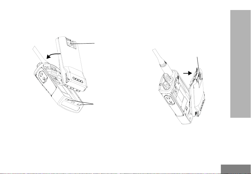
Removing the Lithium-Ion (Li-Ion) Battery
RADIO OVERVIEW
1. Turn OFF the radio.
2. With the Motorola Solutions logo side up on the
battery pack, fit the tabs at the bottom of the
battery into the slots at the bottom of the radio’s
body.
3. Press the top part of the battery towards the
17
1. Turn OFF the radio.
2. Push down the battery latch and hold it while
removing the battery.
3. Pull the battery away from the radio.
Page 20
English
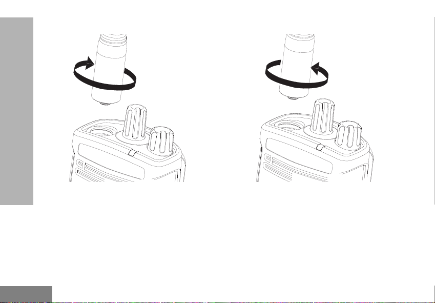
Attaching the Antenna
RADIO OVERVIEW
Removing the Antenna
1. Align the threaded end of the antenna with the
radio’s antenna connector.
2. Turn the antenna clockwise to fasten it.
18
1. Turn the antenna counter-clockwise until you
can remove it.
Note: These instructions apply ONLY to models
RDU4100 and RDV5100. Do not attempt to
remove the antenna if your radio is not one
of these models.
Page 21
English
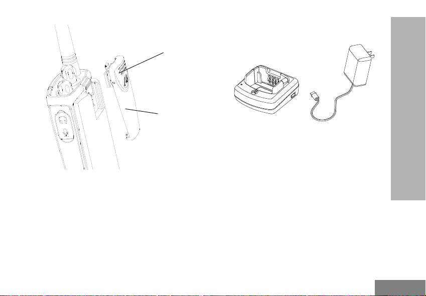
Installing Spring Action Belt clip.
Belt Clip
Tab
Spring Action
Belt Clip
Drop-in Tray Charger Power Supply
1. Slide the spring action belt clip rails into the belt
clip grooves on the back of the battery pack and
slide it down until the belt clip tab snaps into
place.
2. To remove, pull back the metal release tab on
the belt clip tab and push the spring action belt
clip upward to remove.
Power Supply, Adaptor and Drop-in Tray Charger
RADIO OVERVIEW
The radio is equipped with one Drop-in Tray Charger
and one Power Supply with Adaptor. For more
information, refer to “Chargers” on page 76.
19
Page 22
English
Battery Life Information
When the Battery Save feature is set to ON
(enabled by default), the battery life lasts
Table 2: Li-Ion Battery Life with Battery Save feature ON
Battery Type 5 W 4 W
High Capacity 15 hr 15 hr
longer. The following table summarizes battery
life estimations:
RADIO OVERVIEW
Note: Battery life is estimated based on 5%
transmit / 5% receive / 90% standby
standard duty cycle.
20
Page 23
English
Charging the Battery
Power Supply
Drop-In Tray
Charger
The RDX Series radio offers two types of
Chargers:
• Standard Charger and,
• Rapid Charger
Note: The radio comes with a Standard Power
Supply.
To charge the battery (with the radio attached),
place it in a Motorola Solutions-approved Dropin Tray Single Unit Charger or Drop-in Tray
Multi Unit Charger.
Note: When acquiring additional chargers or
power supplies, make sure you have similar
drop-in tray chargers and power supplies
sets (all “rapid” or all “standard”). For part
number details, refer to “Chargers” on
.
page 76
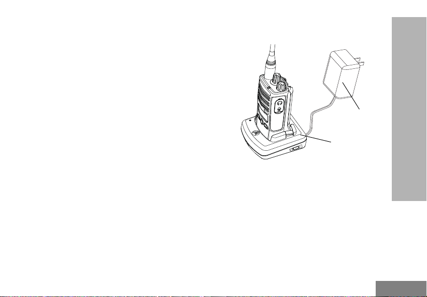
Charging with the Drop-in Tray Single Unit Charger (SUC)
RADIO OVERVIEW
1. Place the Drop-in Tray Charger on a flat
surface.
2. Insert the connector of the Power Supply into
the charger port on the back of the Drop-in Tray
Charger.
3. Plug the AC Adaptor into a power outlet.
4. Insert the radio into the Drop-in Tray Single Unit
Charger with the radio facing the front, as
shown.
21
Page 24
English
Note: When charging a battery attached to the
radio, turn the radio OFF to ensure a full
charge. See “Operational Safety Guidelines”
on page 11 for more information.
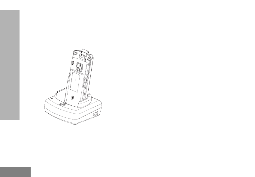
Charging A Stand-Alone Battery
RADIO OVERVIEW
To charge only the battery - at step 4 on page 21,
insert the battery into the tray, with the inside surface
of the battery facing the front of the Drop-in Tray
Single Unit Charger as shown above. Align the slots in
the battery with the alignment ribs in the Drop-in Tray
Single Unit Charger.
Note: Ensure that the bracket in the charger is
adjusted to the correct position for either
Standard or High capacity battery. See
“Charging a Standard Battery” on the right.
22
Page 25

English
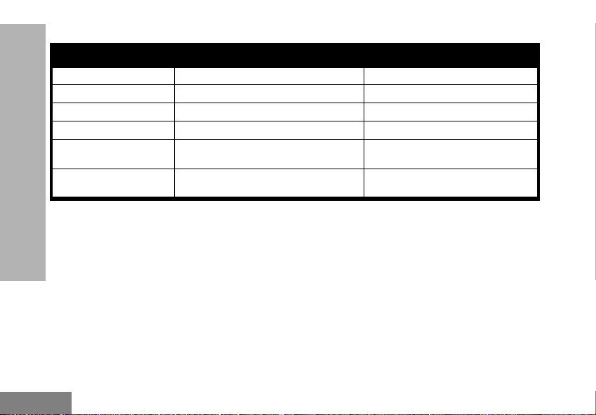
Drop-in Tray Charger LED Indicators
Table 3: Standard Charger LED Indicator
Status LED Indicator Comments
Power On Steady red indication for 3 s The charger has powered up
Charging Blinking red (slow) The charger is currently charging
Charging Complete Steady red indication Battery is fully charged
Battery Fault (*) Blinking red (fast)
(*) Normally, re-positioning the battery pack will
correct this issue.
23
RADIO OVERVIEW
Battery had a fault when battery was
inserted
Page 26
English
Table 4: Rapid Charger LED Indicator
Status LED Indicator Comments
Power On Steady green indication for 3 s The charger has powered up
Charging Blinking green The charger is currently charging
Top-off Charging Blinking green (slow) Battery is near fully charged
Charging Complete Steady green indication Battery is fully charged
Battery Fault (*) Blinking red (fast)
Waiting to Charge (**) Double-blink yellow indications
(*) Normally, re-positioning the battery pack will
RADIO OVERVIEW
correct this issue.
(**) Battery temperature is too warm or too cold or
wrong power voltage is being used.
Battery had a fault when battery was
inserted
Battery charging conditions not
suitable
24
Page 27
English
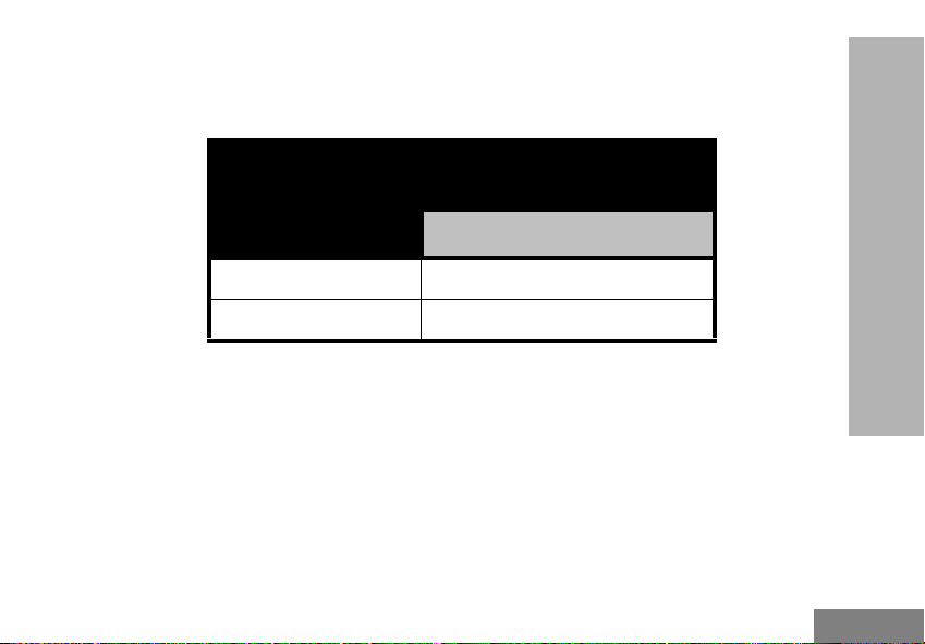
Estimated Charging Time
The following table provides the estimated
charging time of the battery. For more
Table 5: Battery Estimated Charging Time
Charging Solutions
Standard 12 hr
Rapid 3 hr
information, see “Audio Accessories” on
page 75.
RADIO OVERVIEW
Estimated Charging Time
High Capacity Battery
25
Page 28
English
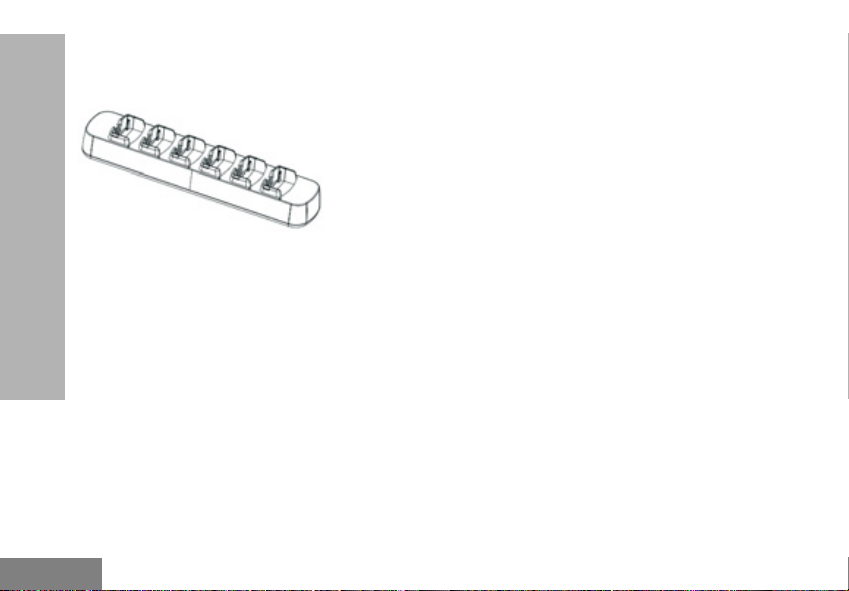
Charging a Radio and Battery using a Multi Unit-Charger - MUC (Optional Accessory)
The Multi-Unit Charger (MUC) allows drop-in
charging of up to six radios or batteries.
Batteries can be charged with the radios or
removed and placed in the MUC separately.
RADIO OVERVIEW
Each of the six charging pockets can hold a
radio (with or without the Holster) or battery, but
not both.
1. Place the Multi-Unit Charger on a flat surface.
2. Insert the power cord plug into the MUC’s dual
pin connector .
3. Plug the power cord into an AC outlet.
4. Turn the radio OFF.
5. Set removable bracket for battery type
6. Insert the radio or battery into the charging
pocket with the radio.
Note:
• This Multi-Unit Charger clones up to three radios
(three Source radios and three Target radios).
Refer to “Cloning with a Multi Unit Charger
(MUC)” on page 53 for more information.
• More information on the Multi-Unit Charger’s
operation is available in the Instruction Sheets
provided with the MUC. For more information on
the parts and their part numbers, refer to Chapter
“Accessories” on page 75.
26
Page 29
English
Multi-Unit Charger LED Indicators
Table 6: MUC Charger LED Indicator
Status LED Indicator Comments
Charging Steady Red Indication The charger is currently charging
Charging Complete Steady Green Indication Battery is fully charged
Battery Fault (*) Blinking red (fast) Battery was faulty when inserted
(*) Normally, re-positioning the battery pack will
correct this issue.
27
RADIO OVERVIEW
Page 30
English
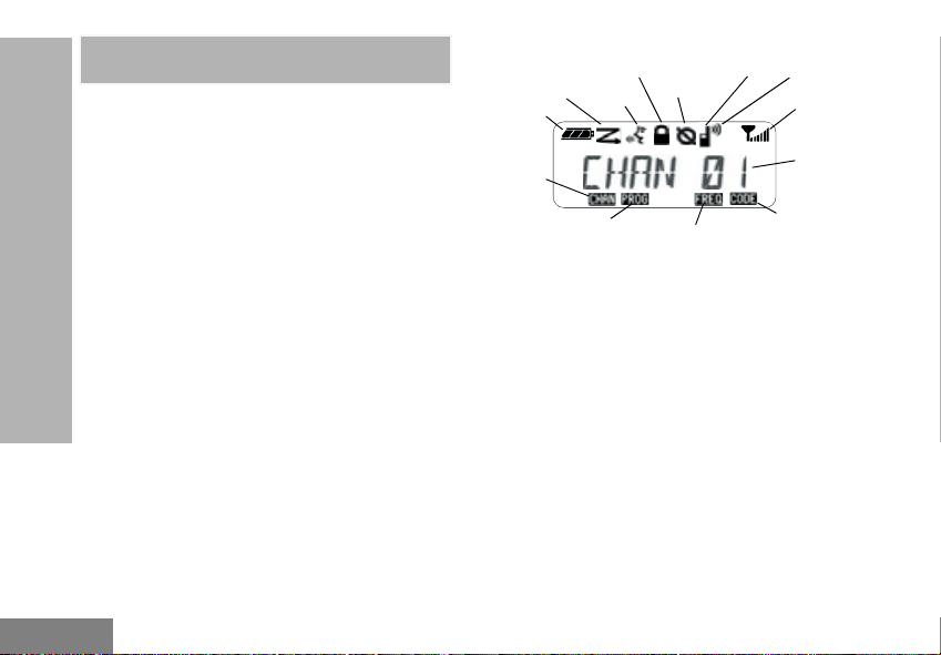
GETTING STARTED
Hi Power
Scramble
Keypad Lock
Vox / iVox
Scan
Battery
Level
Signal
Strength
Channel
Number
Interference
Eliminator Code
Indicator
Frequency
Indicator
Programming
Mode
Indicator
Channel
Indicator
GETTING STARTED
For the following explanations, refer to “Parts Of The
Radio” on page 12.
TURNING RADIO ON/OFF
To turn ON the radio, rotate the On/Off/Volume Knob
clockwise. The radio plays one of the following:
• Power up tone and channel number
announcement, or
• Battery level and channel number
announcements, or
• Silent (Audible tones disabled)
The LED blinks red briefly.
To turn the radio OFF, rotate the On/Off/Volume Knob
counterclockwise until you hear a ‘click’ and the radio
LED Indicator turns OFF.
ADJUSTING VOLUME
Turn the On/Off/Volume Knob clockwise to increase
the volume, or counterclockwise to decrease the
volume.
Note: Do not hold the radio too close to the ear
28
when the volume is high or when adjusting
the volume
READING THE DISPLAY
Note: The radio display shown here is for icon
location only. Each radio display may
appear different (channel and code) based
on the pre-programmed radio defaults and
features available in the model or region.
Pressing any button, except the PTT button,
will turn on the backlight.
SELECTING A CHANNEL
To select a channel, turn the Channel Selector Knob
until you reach the desired channel. An audible voice
indicates the selected channel.
Each channel has its own Frequency, Interference
Eliminator Code and Scan Settings.
Page 31

English
TALKING AND MONITORING
Signal
Strength
Indicator
It is important to monitor for traffic before transmitting
to avoid ‘talking over’ someone who is already
transmitting
To monitor, long press and hold the SB1(*) button to
access channel traffic. If no activity is present, you will
hear ‘static’. To release, press SB1 again. Once
channel traffic has cleared, proceed with your call by
pressing the PTT button. When transmitting, the LED
Indicator stays solid red.
• To listen to all activity on a current channel, short
press the SB1 to set the CTCSS/DPL code to 0.
This feature is called ‘CTCSS/DPL Defeat
(Squelch set to SILENT)’.
• (*) This assumes SB1 is not being programmed
for a different mode.
RECEIVING A CALL
1. Select a channel by rotating the Channel
Selector Knob until you reach the desired
channel. An audible voice indicates the
selected channel.
2. Make sure the PTT button is released and listen
for voice activity.
29
3. The LED Indicator stays solid red when the
radio is receiving a call.
4. To respond, hold the radio vertically 1 to 2
inches (2.5 to 5cm) from mouth. Press the PTT
button to talk; release it to listen.
SIGNAL STRENGTH INDICATOR AND CHANNEL BUSY INDICATORS
When there is activity on a frequency, the radio
displays the Signal Strength Indicator icon and the
radio LED blinks faster. When your radio is receiving
(Rx) and there is activity on the same frequency and
code as your radio, the radio Signal Strength Indicator
icon can change from 1 (weakest) to 6 (strongest)
depending on the radio reception coverage. This
helps you to determine if your radio is moving out of
range.
Note: Obstacles blocking the signal path affects
the strength of incoming signal.
GETTING STARTED
Page 32

English
TALK RANGE
TALK RANGE
Industrial Multi-Level
Model
UHF 4W Up to 350,000 ft2 Up to 30 Floors
To establish a proper two-way communication, the
channel, frequency, and interference eliminator codes
must be the same on both radios. This depends on
GETTING STARTED
the stored profile that has been preprogrammed on
the radio:
1. Channel: Current channel that the radio is
using, depending on radio model.
2. Frequency: The frequency the radio uses to
transmit/receive.
3. Interference Eliminator Code: These codes
help minimize interference by providing a
choice of code combinations.
Inside steel/
concrete Industrial
buildings
Inside multi-
level buildings
4. Scramble Code: Codes that make the
transmissions sound garbled to anyone
listening who is not set to that specific code.
5. Bandwidth: Some frequencies have selectable
channel spacing, which must match other
radios for optimum audio quality.
For details on how to set up frequencies and CTCSS/
DPL codes in the channels, refer to “Advanced
Configuration Mode” on page 36.
30
Page 33

English
RADIO LED INDICATORS
RADIO STATUS LED INDICATION
Channel Busy Solid Orange
Cloning Mode Double Orange Heartbeats
Cloning In Progress Solid Orange
Fatal Error at Power up
Low Battery Orange Heartbeat
Low Battery Shutdown Fast Orange Heartbeat
Monitor LED is OFF
Power-Up Solid Red for 2 s
‘Idle’ Programming Mode /
Channel Mode
Scan Mode Fast Red Heartbeat
Transmit (TX)/Receive (RX) Solid Red
Transmit in Low Power Select Solid Orange
VOX/iVOX Mode Double Red Heartbeats
One Green Blink, One Orange Blink, One Green Blink, then repeat for 4
seconds
Green Heartbeat
GETTING STARTED
31
Page 34

English
HANDS-FREE USE/VOX
VOX
Accessory
Accessory Port/
Connector
Motorola Solutions RDX Series radios can operate
hands-free (VOX) when used with compatible VOX
GETTING STARTED
accessories.
With Compatible VOX Accessories
The default factory setting for VOX sensitivity level is
OFF (level ‘0’). Before using VOX, set VOX level to a
level different from ‘0’ via the Customer Programming
Software (CPS). Then, perform the following steps:
1. Turn the radio OFF.
2. Open accessory cover.
3. Insert the audio accessory’s plug firmly into
accessory port.
4. Turn radio ON. The LED Indicator will blink
double red
5. Lower radio volume BEFORE placing
accessory near ear.
6. To transmit, speak into accessory microphone
and to receive, stop talking.
7. VOX can be temporarily disabled by pressing
the PTT button or by removing the audio
accessory.
VOX can also be activated using the (Menu) button
without using the CPS.
Note: To order accessories, refer to:
www.motorolasolutions.com/RDX,
call 1 (800) 448-6686, or contact your
Motorola Solutions point of purchase.
Hands Free without Accessories (iVOX)
• Press the PTT button while turning ON the radio
to enable iVOX. The icon blinks.
• iVOX can be temporarily disabled by pressing the
32
Page 35

English
PTT button.
Keypad Lock
icon
• A short press of the PTT Button re-enables iVOX
Note:
• There is a short delay between the time when you
start talking and when the radio transmits.
• For more information on setting VOX/iVOX
sensitivity, refer to “Setting VOX/IVOX Sensitivity”
on page 34.
TOGGLE VOICE PROMPT IN USER MODE
Short press the SB1 Button while turning ON the radio
to enable/disable the Voice Prompt in User Mode.
(Default is set to ON).
POWER UP - TONE MODE
To enable/disable power up tone mode, press SB1
and SB2 buttons simultaneously for 2-3 seconds while
powering up the radio until you hear the preprogrammed power up tone. Three different power-up
tones are available.
• Power up tone and channel number
announcement, or
• Battery level and channel number
announcements, or
33
• Silent (Audible tones disabled)
RESET TO FACTORY DEFAULTS
Reset to Factory Defaults will set back all radio
features to the original factory default settings. To do
so, press PTT, SB2 and SB1 simultaneously while
turning ON the radio until you hear a high tone chirp.
KEYPAD BEEPS
To enable/disable Keypad Beeps, short press the SB2
button while turning ON the radio until you hear ‘chirp’
tone.
KEYPAD LOCK/UNLOCK
You can lock the keypad to avoid accidentally
changing your radio settings. To lock the radio
keypad, press and hold the (Menu) button for 4
seconds.
Note: The PTT Button and Programmable Button
A (if Call Tone feature has been assigned)
cannot be locked using this feature.
GETTING STARTED
Page 36

English
MENU OPTIONS
To access the radio MENU, short press the (Menu)
button. The radio displays the feature options. For
each options, use the and buttons to navigate. After
selecting your desired option settings, you can:
• Press (Menu) button to save and go to the next
option, or
• Long press the PTT button to save and exit, or
• Turn OFF the radio to exit without saving the
changes.
The MENU mode times out automatically if there is no
activity detected for more than 10 seconds.
SETTING VOX/IVOX SENSITIVITY
The VOX/iVOX sensitivity settings can be adjusted via
GETTING STARTED
the MENU as well as the CPS. To modify via the
MENU, make sure you have enabled VOX or iVOX.
(Refer to “Hands-Free Use/VOX” on page 33 or
“Hands Free without Accessories (iVOX)” on page 34
for more information). Once VOX/iVOX is enabled,
short press the (Menu) button.
If iVOX is enabled when you press the (Menu) button,
the radio displays the following:
If VOX is enabled (with accessory connected to the
radio) when you press the (Menu) button, the radio
displays the following:
To change the sensitivity level, use the Programmable
Button A and Programmable Button B buttons:
• 0 = OFF (For VOX accessories only)
• 1 = Low sensitivity
• 2 = Medium sensitivity
• 3 = High sensitivity
Once you have selected the desired sensitivity level,
you can:
34
Page 37

English
• Press the (Menu) button to go to the next step,
or
• Turn OFF the radio to exit without saving
changes.
Note: The default sensitivity is ‘Medium’ for VOX
and ‘High’ for iVOX.
MICROPHONE GAIN
The sensitivity of the microphone can be adjusted to
fit different users or operating environments.
This feature can be adjusted only through the CPS.
Microphone default setting is set to level 2 (medium
gain).
GETTING STARTED
35
Page 38

English
PROGRAMMING FEATURES
Advanced Configuration Mode
PROGRAMMING
FEATURES
ADVANCED CONFIGURATION MODE
Advanced Configuration is a configuration mode that
allows the customization of additional features via the
radio’s front panel.
Entering Advanced Configuration Mode
To enter Advanced Configuration Mode, press and
hold the PTT Button and the SB1 Button
simultaneously for 3 s, while turning ON the radio. A
unique tone sounds, indicating the radio has entered
Advanced Configuration Mode. The radio LED blinks
a green heartbeat.
Note:
• The Advanced Configuration Mode defaults to
the ‘Idle’ Programming Mode.
• ‘Idle’ Programming Mode is the stage in the
Programming Mode where the radio waits for
the user to start the radio programming cycle.
When the radio is set to Advanced Configuration
Mode, the k icon displays and the current channel
aliasing name blinks to indicate that you can rotate the
36
Channel Selector Knob to select the channel you want
to program.
In Advanced Configuration Mode, the radio is capable
of setting values for each channel by toggling between
the different programming modes available:
• Frequencies,
• CTCSS/DPL Codes (Interference Eliminator
Code),
• Scramble,
• Maximum Channels,
• Call Tone,
• Microphone Gain,
• Scan, and
• Weather Channel.
• To move along the different Programming
Selection Mode without saving changes, short
press the PTT Button or (Menu) Button.
• To save changes, long press the PTT Button.
The radio returns to ‘Idle’ Programming Mode.
Page 39

English
• When in ‘Idle’ Programming Mode, long press
the PTT button to exit the Programming Mode.
• Whenever you wrap around to the beginning of
the Programming Mode options, the radio
automatically saves all changes made, even if
you turn OFF the radio.
• Exit the Programming Mode without saving
changes (as long as you have not wrapped
around to the beginning of the Programming
Mode options) by turning OFF the radio.
PROGRAMMING RX (RECEPTION) FREQUENCIES
Once you have chosen the channel you want to
program, short press the PTT button or (Menu) button
to scroll through the options until you reach
‘Frequency Programming Mode’.
The radio display shows the frequency code as
follows:
To program the desired frequency, use the
Programmable Button A and Programmable Button B
buttons to navigate to the frequency code value you
need. Long press the PTT button to exit and save, or
short press the PTT button to move to the next
programming feature without saving.
PROGRAMMING RX (RECEPTION) CODES (CTCSS/DPL)
Once you have chosen the channel you want to
program, short press the PTT button or (Menu) button
to scroll through the options until you reach the ‘Code
Programming Mode’.
The radio display shows the CTCSS/DPL code as
follows:
To program the desired code, use the and buttons
until you get the CTCSS/DPL code value you want to
set up. Long press the PTT button to exit and save, or
short press the PTT button to move to the next
programming feature without saving.
PROGRAMMING FEATURES
37
Page 40

English
PROGRAMMING FEATURES
MA
X
CH
PROGRAMMING SCRAMBLE
The scramble feature makes your transmissions
sound garbled to anyone listening without the same
scramble code. It does not guarantee confidentiality,
but it adds an extra layer of privacy. Scramble mode is
by default set to ‘OFF’.
Once you have entered Advanced Configuration
Mode and selected the channel in which you want to
enable Scramble, scroll up or down through the
programming modes by short pressing the PTT button
or (Menu) button until the radio reaches the Scramble
Programming Mode.
The radio display shows the Scramble settings as
follows:
The current scramble value blinks. You can select the
desired scramble value (0,1,2 or 3) by pressing the
and buttons. Long press the PTT button to exit and
save, or short press the PTT button to move to the
next programming feature without saving.
38
Note: The values available for scrambling are
dependent to the values programmed viathe
CPS. Scramble is disabled when the value
is set to ‘0’.
PROGRAMMING MAXIMUM NUMBER OF CHANNELS
You can configure the maximum number of channels
for the radio. Once you have entered the Advanced
Configuration Mode, scroll up or down through the
programming modes by short pressing the PTT button
or (Menu) button until you reach the ‘Maximum
Channel Programming Mode’.
The radio display shows the Maximum Number of
Channels as follows:
The radio display blinks the current maximum number
of channels programmed. Use the Programmable
Button A and Programmable Button B buttons until
you get the desired maximum number of channels.
Long press the PTT button to exit and save, or short
Page 41

English
press the PTT button to move to the next
programming feature without saving.
The values available for maximum channel settings
are dependent on the maximum number of channels
the radio supports.
PROGRAMMING CALL TONES
Call Tones feature allows you to transmit an audible
tone to other radios on the same channel to alert them
that you are about to talk or to alert them without
speaking.
In ‘Call Tone Selection Mode’ you can configure the
type of call tone for the radio. The settings available
are dependent on the maximum number of call tones
your radio supports.
To program Call Tones, enter the Advanced
Configuration Mode and scroll up or down through the
programming modes until your display radio shows
the ‘Programming Call Tones’ selection by short
pressing the PTT button or (Menu) button.
The radio display shows the Programming Call Tone’
as follows:
The radio display blinks the current call tone setting.
You can select the desired call tone value (0,1,2 or 3)
by pressing the Programmable Button A and
Programmable Button B buttons. Each time you select
a different value, your radio sounds the selected call
tone (except for value ‘0’). Once you have selected
the desired call tone, long press the PTT button to exit
and save, or short press the PTT button to move to
the next programming feature without saving.
Note: The values available for Call Tones settings
are dependent on the values programmed
via the CPS. Call Tones is disabled when
the value is set to ‘0’.
PROGRAMMING MICROPHONE GAIN LEVEL
To configure the Microphone Gain Level, enter the
Advanced Configuration Mode and scroll up or down
PROGRAMMING FEATURES
39
Page 42

English
PROGRAMMING FEATURES
through the programming modes by short pressing
the PTT button or (Menu) button until you reach the
‘Microphone Gain Level Programming Mode’.
The radio display shows the Microphone Gain Level
as follows:
The radio display blinks the current Microphone Gain
Level setting. You can select the desired Microphone
Gain Level (1 = low gain, 2 = medium gain or 3 = high
gain) by pressing the Programmable Button A and
Programmable Button B buttons.
Once you have selected the desired Microphone Gain
Level, long press the PTT button to exit and save, or
short press the PTT button to move to the next
programming feature without saving.
Note: The values available for Microphone Gain
Level settings are dependent on the
maximum Microphone Gain Level the radio
supports.
40
PROGRAMMING MICROPHONE ACCESSORY GAIN LEVEL
To configure the Microphone Accessory Gain Level,
enter the Advanced Configuration Mode and scroll up
or down through the programming modes by short
pressing the PTT button or (Menu) button.
The radio display shows the Microphone Accessory
Gain Level as follows:
The radio blinks the current Microphone Accessory
Gain Level setting. You can select the desired
Microphone Accessory Gain Level (1 = low gain, 2 =
medium gain or 3 = high gain) by pressing the
Programmable Button A and Programmable Button B
buttons.
Once you have selected the desired Microphone Gain
Level, long press the PTT button to exit and save, or
short press the PTT button to move to the next
programming feature without saving.
Note: The values available for Microphone
Accessory Gain Level settings are
Page 43

English
dependent on the maximum Microphone
Accessory Gain Level the radio supports.
OTHER PROGRAMMING FEATURES
Scan
Scan allows you to monitor other channels to detect
conversations. When the radio detects a transmission,
it stops scanning and goes to the active channel. This
allows you to listen and talk to people in that channel
without having to change channel manually. If there is
talking going on Channel 2 during this time, the radio
stays on Channel 1 and you will not hear Channel 2.
After talking has stopped in Channel 1, the radio waits
for 5 seconds before resuming scan again.
• To start scanning, press the SB1 or SB2
button. When the radio detects channel activity,
it stops on that channel until activity on that
channel ends. You can talk to the person(s)
transmitting without having to switch channels
by pressing the PTT button.
Note: Scan has to be programmed either to SB1
or SB2 button via CPS. SB2 is by default
Scan/Nuisance Channel delete button. If
Auto-Scan has been enabled for a particular
channel, do not press SB1 or SB2
(programmed for scan) to start scanning, as
the radio does it automatically.
• To stop scanning, short press the SB1 or SB2
button (programmed for scan) again.
• By pressing the PTT button while the radio is
scanning, the radio will transmit on the channel
which was previously selected before Scan is
activated. If no transmission occurs within 5
seconds, scanning resumes.
• If you want to scan a channel without the
Interference Eliminator Codes (CTCSS/DPL),
set the code settings for the channels to ‘0’ in
the CTCSS/DPL Programming Selection
Mode.
Note: Whenever the radio is set to Scan, the LED
Indicator blinks a Red Heartbeat.
Programming Scan List
You can enable or disable the Channel Scanning
feature for each channel in your radio. To do so, enter
the Advanced Configuration Mode and select the
channel you want to program. Scroll through the
programming modes by short pressing the PTT button
or (Menu) button until you reach the ‘Scan
Programming Mode’.
PROGRAMMING FEATURES
41
Page 44

English
The radio display shows the Scan Programming Mode
as follows:
Both the channel number and current scan setting
(YES = Enable or NO = Disable) blinks on the display,
indicating you can choose your setting. To set the
channel number, rotate the Channel Selector Knob
until you reach the desired channel number.
Once you have selected the channel, proceed to
enable (‘YES’) or disable (‘NO’) the scan feature by
pressing the SB2 (*) button. Once you have set the
values you need, long press the PTT button to exit
and save, or short press the PTT button to move to
PROGRAMMING FEATURES
the next programming feature without saving.
Note:
• (*) This assumes the SB2 button is not
programmed for a different mode.
• If the Maximum Channel setting in the radio is
set to ‘1’, the Scan Programming option is
disabled and will not show on the radio display.
Programming Weather Channel (Not allowed on RDX4163)
Weather Channel Programming Mode is the last
programming mode available. You can enable or
disable the Weather Channel.
To do so, enter the Advanced Configuration Mode and
select the channel you want to program. Scroll
through the programming modes by short pressing
the PTT button or (Menu) button until you reach the
‘Weather Channel Programming Mode’.
Press the Programmable Button A and Programmable
Button B buttons to enable or disable the mode. Refer
to “Weather Channel Frequencies Table” on page 47
for the frequency table.
Editing Channel Alias Name
To edit a Channel Alias Name, turn ON the radio and
press and hold the PTT button simultaneously with the
button for 3 seconds. The radio generate a special
beep upon entering the ‘Channel Alias Mode’.
42
Page 45

English
The radio display shows the current channel alias
name and channel number blinking as follows:
Choose the channel number you want to edit by
rotating the Channel Selector Knob. Once you have
selected the channel number, short press the PTT
button or (Menu) button to start editing the channel
alias name.
The character to be changed starts blinking. If it’s a
blank character, a cursor starts blinking.
To change character, press the and buttons until the
desired character is reached. To move to next
character on the right, press the (Menu) button. The
character sequence is [A-Z], “”, (Blank Space), [0-9]
and Special Characters. No lower case is allowed.
Long press the PTT button to save and go back to the
‘Channel Alias Mode’ to choose other channel to edit
the alias name or turn OFF the radio to exit without
saving the changes
Note: If the channel alias name is left blank, long
pressing the PTT button does not save or
leave the alias name.
Nuisance Channel Delete
Nuisance Channel Delete allows you to temporarily
remove channels from the Scan List. This feature is
useful when irrelevant conversations on a ‘nuisance’
channel ties up the radio’s scanning feature.
To delete a channel from the Scan List:
• Start Scan mode by short pressing the SB2(*)
button.
• Wait until the radio stops at the channel you wish
to eliminate. Long press the SB2 button to delete
it. You cannot delete the channel with scan
enabled (home channel).
• The channel will not be scanned again until you
exit the Scan mode by short pressing the SB2
button again or by turning OFF the radio and
back ON.
Note: (*) This assumes the SB2 button is not
programmed for a different mode.
PROGRAMMING FEATURES
43
Page 46

English
PROGRAMMING FEATURES
Drop-In Tray
Charger Tray
Radio to be
programmed
USB Ports
CPS Programming
Cable
CUSTOMER PROGRAMMING SOFTWARE (CPS)
Figure 1: Setting up the radio to the CPS
The easiest way to program or change features in
your radio is by using the Customer Programming
Software (CPS) and the CPS Programming Cable(*).
CPS Software is available for free as web based
downloadable software at:
www.motorolasolutions.com/RDX
To program, connect the RM Series radio via the
Drop-in Charger Tray and CPS Programming Cable
as shown in Figure 1 on page 44. Toggle the cable
44
switch of the CPS Programming Cable to ‘CPS
Mode’.
CPS allows you to program frequencies, PL/DPL
Codes as well as other features such as: Bandwidth
Select, Time-out Timer, Power Select, Scan List, Call
Tones, Scramble, Reverse Burst, etc. CPS is a very
useful tool as it can also lock the Front-Panel Radio
Programming or restrict any specific radio feature to
be changed (to avoid accidentally erasing the preset
radio values). It also provides security by giving the
option to set up a password for profile radio’s
management. For more information, refer to Features
Summary Chart Section at the end of the User Guide.
Note: (*) CPS Programming Cable P/N#
HKKN4027_ is an accessory sold
separately. Please contact your Motorola
point of purchase for more information.
Time-Out Timer
This timer sets the amount of time that the radio can
continuously transmit before the transmission is
automatically terminated. The default setting is 60
seconds and can be changed using the CPS.
Power Select
Power Select allows you to select between high and
low transmission power per frequency in each
Page 47

English
channel. The High Power for RDX+ is 5 W for VHF
and 4 W for UHF, Low Power for both bands is 2 W.
Note: Some frequencies may have FCC transmit
power restrictions that disallow them to be
set at a higher power level. For more
information, refer to the “Frequency and
Code Charts” on page 63.
Call Tones
See “Programming Call Tones” on page 39.
Scramble
See “Programming Scramble” on page 38.
Reverse Burst
Reverse Burst eliminates unwanted noise (squelch
tail) during loss of carrier detection. You can select
values of either 180 or 240 to be compatible with other
radios.
Note:
• The features described in previous pages are just
some of the features CPS has. CPS offers more
capabilities. For more information refer to the
HELP file in the CPS.
• Some of the features available with the CPS
software may vary depending on the radio model.
PROGRAMMING FEATURES
TEXT-TO-SPEECH (CHANGING PREDEFINED VOICE ALIASES)
Enable User Pre-Defined Voice Prompt (VP) Checkbox
Check the box to enable user-defined voice on the
selected channel. The user is given the option to
either use the Text-to-Speech synthesizer in order to
generate automated voice, or import a wave (.wav) file
containing the voice data.
User Pre-Defined Voice Prompt (VP) Text
This field is used by the Text-to-Speech synthesizer
embedded in the CPS to generate user-defined voice
for the selected channel.
Note:
• The length of the string cannot exceed 18
characters.
• The string can only contain ISO-8859-1
characters.
Import Voice File
This field allows the user to upload a pre-existing
wave (.wav) file from the local hard drive. The first
45
Page 48

English
eight characters of the wave files are used to populate
the channel “Name”.
Note:
• The wave file must be sampled at 8 kHz.
• The wave file cannot exceed 65,000 kB in
length.
Listen to User Customized Voice Prompt (VP) Text
This field allows the user to play the output voice
signal generated from the Text-to-Speech synthesizer.
WEATHER FEATURE (NOT FOR RDU4163)
The RDX radio weather mode can be programmed to
operate and receive weather channels that are
broadcast by the National Weather Radio (NWR). The
NWR system is a nationwide network of radio stations
PROGRAMMING FEATURES
(more than 1000 stations in United States) that
broadcast continuous weather information for the
public. The NWR broadcasts all types of weather
service warnings, watches, forecasts and other
hazard information. The NWR can also broadcast
non- weather alerts such as national security, natural,
environmental, and public safety in conjunctions with
the Emergency Alert System (EAS).
The RDX radio weather feature can detect weather
alerts/warnings that are broadcast by NWR. The
RDX+ radio can be programmed to detect the analog
tone or digital-over-audio protocol. The analog tone is
a 1050 Hz tone (Warning Alarm Tone), which is issued
for 10 seconds immediately before the warning
message by the NWR transmitter. When RDX radio
detects the Warning Alarm tone, it unmutes audio and
allows the user to hear the weather alert message. As
for digital-over- audio protocol, it is a newer
technology called Specific Area Message Encoding
(SAME) that allows weather radio to receive digital
data stream about the type of weather events, timing,
duration, and location. When RDX radio detects these
special warnings, the radio can be programmed to
automatically generate a loud tone, enable LED
indicator, and display “hazard” status on the display.
With the SAME technology, the RDX radio weather
mode can be programmed to detect the type of
weather warnings or watches for a specified the
county or counties.
Further information about the National Weather Radio
system such as network updates, transmitter
coverage maps, and SAME event codes can be found
on the Internet at www.nws.noaa.gov/nwr/.
46
Page 49

English
Weather Alert Mode
Select the alert mode the radio will respond to alerts
sent from the National Weather Service, which
transmitted prior to the broadcast of any message
about a life or property threatening event.
Choices available are:
• OFF (Default): Disable the Weather Alert
Feature.
• Tone Alert: Detect the Warning Alarm Tone
(WAT).
• SAME Alert: Detect the Special Area Message
Encoding (SAME).
Weather Channel Frequencies Table
Frequency Number Value (Mhz)
1 162.4000
2 162.4250
3 162.4500
Frequency Number Value (Mhz)
4 162.4750
5 162.5000
6 162.5250
7 162.5500
THE WEATHER ALERT HAS TWO MODES OF OPERATIONS
1. In Weather Channel Mode, the radio is in a
muted state until it detects the WAT/SAME.
When the radio detects the WAT, the radio
unmutes and allows the user to hear the
weather alert message.
2. In two-way mode (on two-way channel),
Weather Alert feature becomes a special scan
feature. The radio scans between the current
selected two-way channel and the selected
weather channel. When the radio detects WAT/
SAME signal on the weather channel, the radio
PROGRAMMING FEATURES
47
Page 50

English
unmutes to allow the user to listen the weather
message. For Tone Alert, the radio stays in
receiving mode until weather signal is weak or
user presses the PTT button or changes the
channel using the Channel Selector Knob. For
SAME alert, whether the radio stays in
receiving mode or switches back to two-way
mode depending on the setting of the EOM
Enabled.
Warning: RDX radio does not detect Weather Alert
while it is receiving or transmitting on a
two-way channel.
EOM Enabled
This feature is only available for SAME Alert mode
PROGRAMMING FEATURES
and it is only effective when the radio operates in twoway mode or Weather Channel mode. When checked
and in two-way mode, the radio switches back to twoway channel and continues to weather scan after it
receives end of message (EOM). For weather
channel, the radio mutes and continues to look for
new SAME alert after it receives EOM. When
unchecked, it stays in receiving mode until weather
signal is weak or user presses the PTT button or
changes the channel using the Channel Selector
Knob.
New Alert Tone Timer
Select a pre-defined time for a radio to play the new
alert tone. When a radio receives a new SAME alert
message, the LED screen lights up and the radio
starts playing the new alert tone at the end of the
message. Users have the ability to configure how long
the alert tone will be played.
Choices available are:
• 0 – forever until a button is pressed, or user
switches channel, or the new alert message is
expired.
•5 min.
• 10 min.
• 30 min.
Note: Embedded in the SAME message is the
duration of the alert message. The RDX
radio continues to display the alert until the
duration expiration time.
EVENT TYPE FILTER
The RDX radio is a programmable weather radio that
allows users to choose the type of weather warnings
48
Page 51

English
and watches that will alarm. The radio can be
programmed to allow or block an event by its type.
All Events
When checked, the radio allows for all SAME events.
Alert Test Event
When SAME alert is enabled, the radio responds to
any test events. When checked, the radio alerts the
same way as other SAME alert messages. When
unchecked, the radio displays only the Message,
lights the alert LED without unmuting the radio. The
radio does not play the new alert tone at this time.
Note: No matter how the user programs the event
filter, some critical events cannot be
blocked. The National Weather Service
broadcast a test alert every week on
Wednesday between 11 AM and Noon.
Users should use test alert to ensure that
their radios are functioning properly. See
also: The Critical Events Table.
WARNING
When checked, the radio allows all warning events.
Warning events are events that alone pose a
significant threat to public safety and/or property.
Note: No matter how the user programs the event
filter, some critical events cannot be
blocked. See also: The Critical Events
Table.
WATCH
When checked, the radio allows all watch events.
Watches are events that meet the classification of a
warning, but either the onset time, probability of
occurrence or location is uncertain.
Note: No matter how the user programs the event
filter, some critical events cannot be
blocked. See also: The Critical Events
Table.
EMERGENCY
When checked, the radio allows all emergency
events. Emergency event is an event that by itself
would not kill or injure or do property damage, but
indirectly may cause other things to happen that result
in a hazard.
Note: No matter how the user programs the event
filter, some critical events cannot be
blocked. See also: The Critical Events
Table.
PROGRAMMING FEATURES
49
Page 52

English
STATEMENT
When checked, the radio allows all statement events.
Statement is message that contains follow-up
information to a warning, watch, or emergency.
Note: No matter how the user programs the event
filter, some critical events cannot be
blocked. See also: The Critical Events
Table.
EVENT CODE FILTER
A specific SAME event can be allowed or blocked.
There are maximum of five Event Codes can be
programmed.
BLOCK EVENT
When checked, the Event Codes entered below shall
be blocked.
PROGRAMMING FEATURES
Note: No matter how the user programs the event
filter, some critical events cannot be
blocked. See also: The Critical Events
Table.
EVENT CODE
The Event Code field accepts wild card (“*”). The
following are examples of valid Event Code format.
• “***” - all events
• FL"*” – FLA or FLW
•FLA
The “blank” means unprogrammed and the radio will
bypass it without doing anything.
Note: No matter how the user programs the event
filter, some critical events cannot be
blocked. See also: The Critical Events
Table.
THE CRITICAL EVENTS TABLE
Abbreviation Description
BHW
Biological Hazard
Warning
CDW Civil Danger Warning
50
CEM
Civil Emergency
Message
Page 53

English
Abbreviation Description
CHW
Chemical Hazard
Warning
Abbreviation Description
FCW
Food Contamination
Warning
PROGRAMMING FEATURES
CWW
DBW Dam Break Warning
DEW
EAN
EAT
EQW Earthquake Warning
EVI
51
Contaminated Water
Warning
Contagious Disease
Warning
Emergency Action
Notification
Emergency Action
Termination
Evacuation
Immediate
HMW
HUW Hurricane Warning
IEW
IFW
LAE
LEW
LSW Land Slide Warning
Hazardous Materials
Warning
Immediate
Evacuation Warning
Industrial Fire
Warning
Local Area
Emergency
Law Enforcement
Warning
Page 54

English
Abbreviation Description
Abbreviation Description
PROGRAMMING FEATURES
52
NHW
NUW
RHW
SPW
National Hazard
Warning
Nuclear Power Plant
Warning
Radiological Hazard
Warning
Shelter In Place
Warning
TOR Tornado Warning
TOW Tornado Warning
TRW
Tropical Storm
Warning
TSA Tsunami Watch
TSW Tsunami Warning
VOW Volcano Warning
WFW Wild Fire Warning
GEOGRAPHIC FILTER
There are maximum of six geographic codes can be
programmed. When all fields are unselected, or any of
the geographic code is “ALL” for both State and
County code (FIPS is “000000”), the radio bypasses
the Geographic Filter check.
There are two ways to enter the geographic code,
• Select State and County Code.
• Enter the FIPS code directly (must be 6 digits).
STATE
Selects the State, Territory and Offshore (Marine
Area) portion (SS) the radio alerts for.
COUNTY
Select a county, province, or major metropolitan area
(CCC) the radio alerts for.
Page 55

English
FIPS
Pocket 1
“CLONE” symbol
Pocket 2 “CLONE” symbol Pocket 5
Pocket 4
Federal Information Processing Standards (FIPS)
contains six digits which represent PSSCCC, where P
is the region code, SS is the state code and CCC is
the county code.
Enters/Edits a specific FIPS whenever it is necessary.
Further information about FIPS can be found on the
Internet at www.nws.noaa.gov/nwr/ indexnw.htm or
call the National Weather Service Toll-Free Number
SAME county code – 1888-NWS-SAME (1-888-697-
7263).
CLONING RADIOS
You can clone RDX Series radio profiles from one
Source radio to a Target radio by using any one of
these three methods:
• Using a Multi Unit Charger (MUC- optional
• Using two Single Unit Chargers (SUC) and a
• the CPS (free software download)
Cloning with a Multi Unit Charger (MUC)
To clone radios using the MUC, there must be at least
two radios:
• a Source radio (the radio which profiles will be
cloned or copied from) and
• a Target radio (the radio which profile will be
accessory),
Radio-to-Radio cloning cable (optional
accessory),
53
cloned from the source radio.)
The Source radio has to be in Pocket 1, 3 or 5 while
the Target radio has to be in Pocket 2, 4 or 6,
matching in the MUCs pockets by pairs as follows:
• 1 and 2 or,
• 3 and 4 or,
• 5 and 6 (*).
PROGRAMMING FEATURES
Page 56

English
When cloning, the MUC does not need to be plugged
into a power source, but ALL radios require charged
batteries.
1. Turn ON the Target radio and place it into one of
the MUC Target Pockets
2. Power the Source radio following the sequence
below:
• Long Press the PTT button and SB2
simultaneously while turning the radio
ON.
• Wait for 3 seconds before releasing the
buttons until the audible tone “Cloning” is
heard.
3. Place the Source radio in the source pocket that
PROGRAMMING FEATURES
pairs with the target pocket you chose in step 1.
Press and release the SB1 button.
4. After cloning is completed, the Source radio will
announce either “successful” (cloning is
successful) or “fail” (cloning has failed). The
‘successful’ tone sounds like a good key ‘chirp’
whereas the ‘fail’ tone sounds similar to a ‘bonk’
tone. If the Source radio is a display model, it
will either show ‘Pass’ or ‘Fail’ on the display (a
tone will be heard within 5 s).
5. Once you have completed the cloning process,
turn the radios OFF and ON or, long press the
PTT button to exit the ‘cloning’ mode.
Further details on how to clone radios are explained in
the Instructions Sheet provided with the MUC.
When ordering the MUC, refer to part number
RLN6309_.
Note:
• If cloning fails, refer to “What To Do If Cloning
Fails” on page 56.
• Paired Target radios and Source radios must be
of the same band type in order for the cloning to
run successfully.
• MUC pockets numbers should be read from left to
right with the Motorola logo facing front.
54
Page 57

English
Cloning Radio using the Radio to Radio
(R2R) Cloning Cable (Optional Accessory)
Operating Instructions
1. Before starting the cloning process, make sure
you have:
• A fully charged battery on each of the radios.
• Two Single-Unit Chargers (SUC).
• Turn OFF the radios and,
• Both radios are of the same radio model.
2. Unplug any cables (power supply or USB
cables) from the SUCs.
3. Plug one side of the cloning cable mini USB
connector to the first SUC and the other end to
the second SUC.
Note: During the cloning process, no power is
being applied to the SUC. The batteries will
not be charged. Only data communication is
being established between the two radios.
4. Turn ON the Target Radio and place it into one
of the SUCs.
5. For the Source Radio, power ON the radio with
the following sequence:
• Long press the PTT button and SB2
simultaneously while turning the radio ON.
• Wait for 3 s before releasing the buttons until a
distinctive audible tone is heard.
6. Place the Source radio in its SUC, press and
release SB1.
7. After cloning is completed, the Source radio will
sound either a ‘pass’ tone (cloning was
successful) or a ‘fail’ tone (cloning process has
failed). The ‘pass’ tone sounds like a good key
PROGRAMMING FEATURES
55
Page 58

English
‘chirp’ whereas the ‘fail’ tone sounds similar to a
‘bonk’ tone. If the Source radio is a display
model, it will either show ‘Pass’ or ‘Fail’ on the
display (a tone will be heard within 5 seconds).
8. Once you have completed the cloning process,
turn the radios OFF and ON to exit ‘clone’
mode.
What To Do If Cloning Fails
The radio will emit an audible “bonk” indicating that
the cloning process has failed. In the event that the
cloning fails, perform each of the following steps
before attempting to start cloning process again:
1. Ensure that the batteries on both radios are fully
charged.
2. Check the cloning cable connection on both
PROGRAMMING FEATURES
SUCs.
3. Ensure that the battery is engaged properly on
the radio.
4. Ensure that there is no debris in the charging
tray or on the radio contacts.
5. Ensure that the Target radio is turned ON.
6. Ensure that the Source radio is in cloning mode.
7. Ensure that the two radios are both from the
same frequency band, same region and have
the same transmission power.
Note: This cloning cable is designed to operate
only with compatible Motorola SUC
RLN6175_ and RLN6304_.
When ordering Optional Cloning Cable, please refer
to part number RLN6303_. For more information
about the accessories, refer to “Accessories” on
page 75.
56
Page 59

English
Drop-In Tray
Charger Tray
Radio to be
programmed
USB Ports
CPS Programming
Cable
Cloning using the Customer Programming Software (CPS)
When cloning using this method, you need the CPS
software, a Drop-In Tray Charger and the CPS
Programming Cable.
To order the CPS Programming Cable, please refer to
part number RKN4155_.
Information on how to clone using the CPS is
available either in:
• the CPS Help File --> Content and Index -->
Cloning Radios, or
• in the CPS Programming Cable Accessory
Leaflet.
57
PROGRAMMING FEATURES
Page 60

English
TROUBLESHOOTING
Symptom Try This...
No Power
Hearing other noises or
conversation on a channel
TROUBLESHOOTING
Message Scrambled
Recharge or replace the Li-Ion battery.
Extreme operating temperatures may affect battery life.
Refer to “About the Li-Ion Battery” on page 15.
Confirm Interference Eliminator Code is set.
Frequency or Interference Eliminator Code may be in use.
Change settings: either change frequencies or codes on all radios.
Make sure radio is at the right frequency and code when transmitting.
Refer to “Talking and Monitoring” on page 29.
Scramble Code might be ON, and/or setting does not match the other radios'
settings.
Audio quality not good
enough
58
Radio settings might not be matching up correctly. Double check frequencies,
codes and bandwidths to make sure they are identical in all radios.
Page 61

English
Symptom Try This...
Steel and/or concrete structures, heavy foliage, buildings or vehicles decrease
range. Check for clear line of sight to improve transmission.
Wearing radio close to body such as in a pocket or on a belt decreases range.
Limited talk range
Message not transmitted or
received
Change location of radio. To increase range and coverage, you can reduce
obstructions or increase power. UHF radios provides greater coverage in
industrial and commercial buildings. Increasing power provides greater signal
range and increased penetration through obstructions.
Refer to “Talking and Monitoring” on page 29.
Make sure the PTT button is completely pressed when transmitting.
Confirm that the radios have the same Channel, Frequency, Interference
Eliminator Code and Scramble Code settings. Refer to “Talking and Monitoring”
on page 29 for further information.
Recharge, replace and/or reposition batteries. Refer to “About the Li-Ion
Battery” on page 15.
Obstructions and operating indoors, or in vehicles, may interfere. Change
location. Refer to “Talking and Monitoring” on page 29.
Verify that the radio is not in Scan. Refer to “Scan” on page 41 and “Nuisance
Channel Delete” on page 43.
TROUBLESHOOTING
59
Page 62

English
Symptom Try This...
Heavy static or interference
Low batteries
Drop-in Charger LED light
does not blink
TROUBLESHOOTING
Low battery indicator is
blinking although new
batteries are inserted
Radios are too close; they must be at least five feet apart.
Radios are too far apart or obstacles are interfering with transmission.
Refer to “Talking and Monitoring” on page 29.
Recharge or replace Li-Ion battery.
Extreme operating temperatures affect battery life.
Refer to “About the Li-Ion Battery” on page 15.
Check that the radio/battery is properly inserted and check the battery/charger
contacts to ensure that they are clean and charging pin is inserted correctly.
Refer to “Charging the Battery” on page 21, “Drop-in Tray Charger LED
Indicators” on page 23 and “Installing the Lithium-Ion (Li-Ion) Battery” on
page 17.
Refer to “Installing the Lithium-Ion (Li-Ion) Battery” on page 17, and “About the
Li-Ion Battery” on page 15.
60
Page 63

English
Symptom Try This...
VOX feature might be set to OFF.
Cannot activate VOX
Battery does not charge
although it has been placed
in the drop-in charger for a
while
Use the CPS to ensure that the VOX Sensitivity level is not set to ‘0’.
Accessory not working or not compatible.
Refer to “Hands-Free Use/VOX” on page 32.
Check drop-in tray charger is properly connected and correspond to a
compatible power supply.
Refer to “Charging with the Drop-in Tray Single Unit Charger (SUC)” on
page 21 and “Charging A Stand-Alone Battery” on page 22.
Check the charger’s LEDs indicators to see if the battery has a problem. Refer
to “Drop-in Tray Charger LED Indicators” on page 23.
TROUBLESHOOTING
User voice prompt does not
clone.
Note: Whenever a feature in the radio seems to not correspond to the default or preprogrammed values,
check to see if the radio has been programmed using the CPS with a customized profile.
61
Check the front radio name plate. Radios with an orange color font will not
support customize voice prompt.
Page 64

English
USE AND CARE
Use a soft damp
cloth to clean
the exterior
Do not immerse
in water
Do not use alcohol
or cleaning
solutions
If the radio is submerged in water...
Turn radio OFF
and remove
batteries
Dry with soft
cloth
Do not use radio
until completely dry
USE AND CARE
62
Page 65

English
FREQUENCY AND CODE CHARTS
RDX UHF FREQUENCIES CHART
The charts in this section provide Frequency
and Code information. These charts are useful
RDX UHF 16CH Radios Default Frequencies – RDU4163
Channel Frequency #
1 1 458.6625 1 67.0 Hz 12.5 kHz
2 2 469.2625 1 67.0 Hz 12.5 kHz
3 1 458.6625 2 71.9 Hz 12.5 kHz
4 2 469.2625 2 71.9 Hz 12.5 kHz
5 1 458.6625 3 74.4 Hz 12.5 kHz
6 2 469.2625 3 74.4 Hz 12.5 kHz
7 1 458.6625 4 77.0 Hz 12.5 kHz
8 2 469.2625 4 77.0 Hz 12.5 kHz
9 1 458.6625 5 79.7 Hz 12.5 kHz
10 2 469.2625 5 79.7 Hz 12.5 kHz
Frequency
(MHz)
when using the Motorola Solutions RDX Series
two-way radios with other business radios.
FREQUENCY AND CODE
RDU4163 – UHF DEFAULT FREQUENCIES CHART
CHARTS
Code# Code Bandwidth
63
Page 66

English
CHARTS
FREQUENCY AND CODE
RDX UHF 16CH Radios Default Frequencies – RDU4163
11 1 458.6625 6 82.5 Hz 12.5 kHz
12 2 469.2625 6 82.5 Hz 12.5 kHz
13 1 458.6625 7 85.4 Hz 12.5 kHz
14 2 469.2625 7 85.4 Hz 12.5 kHz
15 1 458.6625 8 88.5 Hz 12.5 kHz
16 2 469.2625 8 88.5 Hz 12.5 kHz
64
Page 67

English
RDX UHF FREQUENCIES CHART
RDX UHF Frequencies
Frequency # Frequency (MHz) Bandwidth Frequency # Frequency (MHz) Bandwidth
1 464.5000 12.5 kHz 15 461.1875 12.5 kHz
2 464.5500 12.5 kHz 16 461.2125 12.5 kHz
*3 467.7625 12.5 kHz 17 461.2375 12.5 kHz
*4 467.8125 12.5 kHz 18 461.2625 12.5 kHz
*5 467.8500 12.5 kHz 19 461.2875 12.5 kHz
*6 467.8750 12.5 kHz 20 461.3125 12.5 kHz
*7 467.9000 12.5 kHz 21 461.3375 12.5 kHz
*8 467.9250 12.5 kHz 22 461.3625 12.5 kHz
9 461.0375 12.5 kHz *23 462.7625 12.5 kHz
10 461.0625 12.5 kHz *24 462.7875 12.5 kHz
11 461.0875 12.5 kHz *25 462.8125 12.5 kHz
12 461.1125 12.5 kHz *26 462.8375 12.5 kHz
13 461.1375 12.5 kHz *27 462.8625 12.5 kHz
14 461.1625 12.5 kHz *28 462.8875 12.5 kHz
FREQUENCY AND CODE
CHARTS
65
Page 68

English
RDX UHF Frequencies (Continued)
Frequency # Frequency (MHz) Bandwidth Frequency # Frequency (MHz) Bandwidth
*29 462.9125 12.5 kHz 47 466.3625 12.5 kHz
30 464.4875 12.5 kHz *48 467.7875 12.5 kHz
31 464.5125 12.5 kHz *49 467.8375 12.5 kHz
32 464.5375 12.5 kHz *50 467.8625 12.5 kHz
33 464.5625 12.5 kHz *51 467.8875 12.5 kHz
34 466.0375 12.5 kHz *52 467.9125 12.5 kHz
CHARTS
FREQUENCY AND CODE
35 466.0625 12.5 kHz 53 469.4875 12.5 kHz
36 466.0875 12.5 kHz 54 469.5125 12.5 kHz
37 466.1125 12.5 kHz 55 469.5375 12.5 kHz
38 466.1375 12.5 kHz 56 469.5625 12.5 kHz
39 466.1625 12.5 kHz 57 462.1875 12.5 kHz
40 466.1875 12.5 kHz 58 462.4625 12.5 kHz
41 466.2125 12.5 kHz 59 462.4875 12.5 kHz
42 466.2375 12.5 kHz 60 462.5125 12.5 kHz
43 466.2625 12.5 kHz 61 467.1875 12.5 kHz
44 466.2875 12.5 kHz 62 467.4625 12.5 kHz
45 466.3125 12.5 kHz 63 467.4875 12.5 kHz
46 466.3375 12.5 kHz 64 467.5125 12.5 kHz
66
Page 69

English
RDX UHF Frequencies (Continued)
Frequency # Frequency (MHz) Bandwidth Frequency # Frequency (MHz) Bandwidth
65 451.1875 12.5 kHz 82 456.4375 12.5 kHz
66 451.2375 12.5 kHz 83 456.5375 12.5 kHz
67 451.2875 12.5 kHz 84 456.6375 12.5 kHz
68 451.3375 12.5 kHz 85 457.3125 12.5 kHz
69 451.4375 12.5 kHz 86 457.4125 12.5 kHz
70 451.5375 12.5 kHz 87 457.5125 12.5 kHz
71 451.6375 12.5 kHz 88 457.7625 12.5 kHz
72 452.3125 12.5 kHz 89 457.8625 12.5 kHz
73 452.5375 12.5 kHz 90 468.2125 12.5 kHz
74 452.4125 12.5 kHz 91 468.2625 12.5 kHz
75 452.5125 12.5 kHz 92 468.3125 12.5 kHz
76 452.7625 12.5 kHz 93 468.3625 12.5 kHz
77 452.8625 12.5 kHz 94 468.4125 12.5 kHz
78 456.1875 12.5 kHz 95 468.4625 12.5 kHz
79 456.2375 12.5 kHz 96 468.5125 12.5 kHz
80 456.2875 12.5 kHz 97 468.5625 12.5 kHz
81 456.3375 12.5 kHz 98 468.6125 12.5 kHz
82 456.4375 12.5 kHz 99 468.6625 12.5 kHz
Note: (*) Frequency limited to 2 W maximum power
output.
67
FREQUENCY AND CODE
CHARTS
Page 70

English
RDU4160 – UHF DEFAULT FREQUENCIES CHART
Channel Frequency #
1 1 464.5000 1 67.0 Hz 12.5 kHz
2 1 464.5000 4 77.0 Hz 12.5 kHz
3 1 464.5000 8 88.5 Hz 12.5 kHz
CHARTS
FREQUENCY AND CODE
4 1 464.5000 29 179.9 Hz 12.5 kHz
5 1 464.5000 0 - 12.5 kHz
6 2 464.5500 1 67.0 Hz 12.5 kHz
7 2 464.5500 6 82.5 Hz 12.5 kHz
8 WC 162.4000 10 67.0 Hz 25.0 kHz
9 2 464.5500 29 179.9 Hz 12.5 kHz
10 2 464.5500 0 - 12.5 kHz
11 22 461.3625 3 74.4 Hz 12.5 kHz
12 30 462.4875 5 79.7 Hz 12.5 kHz
13 32 462.5375 7 85.4 Hz 12.5 kHz
RDX UHF 16CH Radios Default Frequencies – RDU4160
Frequency
(MHz)
Code # Code Bandwidth
68
Page 71

English
RDX UHF 16CH Radios Default Frequencies – RDU4160
14 34 462.0375 9 91.5 Hz 12.5 kHz
15 36 464.0875 11 97.4 Hz 12.5 kHz
16 38 464.1375 13 103.5 Hz 12.5 kHz
Note: WC = Weather Channel Frequency
PROGRAMMING CUSTOMIZED FREQUENCIES ON RDU4160
4 W Models can be programmed to have
customized frequencies (different from the
ones shown in the UHF charts in previous
pages). UHF range is 438 – 470 MHz.
4 W models can also be programmed to work
with repeaters. Please contact your Motorola
Solutions point of purchase for details.
FREQUENCY AND CODE
CHARTS
69
Page 72

English
CTCSS AND PL/DPL CODES
CTCSS Hz CTCSS Hz CTCSS Hz
1 67.0 14 107.2 27 167.9
2 71.9 15 11 0.9 28 173.8
3 74.4 16 114.8 29 179.9
4 77.0 17 11 8.8 30 186.2
5 79.7 18 123 31 192.8
CHARTS
FREQUENCY AND CODE
6 82.5 19 127.3 32 203.5
7 85.4 20 131.8 33 210.7
8 88.5 21 136.5 34 218.1
9 91.5 22 141.3 35 225.7
10 94.8 23 146.2 36 233.6
11 97.4 24 151.4 37 241.8
12 100.0 25 156.7 38 250.3
13 103.5 26 162.2 122 (*) 69.3
Note: (*) New CTCSS code.
CTCSS Codes
70
Page 73

English
PL/DPL Codes
DPL Code DPL Code DPL Code
39 23 55 116 71 243
40 25 56 125 72 244
41 26 57 131 73 245
42 31 58 132 74 251
43 32 59 134 75 261
44 43 60 143 76 263
45 47 61 152 77 265
46 51 62 155 78 271
47 54 63 156 79 306
48 65 64 162 80 311
49 71 65 165 81 315
50 72 66 172 82 331
51 73 67 174 83 343
52 74 68 205 84 346
53 114 69 223 85 351
54 115 70 226 86 364
FREQUENCY AND CODE
CHARTS
71
Page 74

English
CHARTS
FREQUENCY AND CODE
PL/DPL Codes (Continued)
DPL Code DPL Code DPL Code
87 365 104 565 121 754
88 371 105 606 123 645
89 411
90 412 107 624 125 Customized PL
91 413 108 627 126 Customized PL
92 423 109 631 127 Customized PL
93 431 11 0 632 128 Customized PL
94 432 111 654 129 Customized PL
95 445 11 2 662 130 Inverted DPL 39
96 464 11 3 664 131 Inverted DPL 40
97 465 11 4 703 132 Inverted DPL 41
98 466 11 5 712 133 Inverted DPL 42
99 503 11 6 723 134 Inverted DPL 43
100 506 11 7 731 135 Inverted DPL 44
101 516 11 8 732 136 Inverted DPL 45
102 532 11 9 734 137 Inverted DPL 46
103 546 120 743 138 Inverted DPL 47
106 612 124 Customized PL
72
Page 75

English
PL/DPL Codes (Continued)
DPL Code DPL Code DPL Code
139 Inverted DPL 48 156 Inverted DPL 65 173 Inverted DPL 82
140 Inverted DPL 49 157 Inverted DPL 66 174 Inverted DPL 83
141 Inverted DPL 50 158 Inverted DPL 67 175 Inverted DPL 84
142 Inverted DPL 51 159 Inverted DPL 68 176 Inverted DPL 85
143 Inverted DPL 52 160 Inverted DPL 69 177 Inverted DPL 86
144 Inverted DPL 53 161 Inverted DPL 70 178 Inverted DPL 87
145 Inverted DPL 54 162 Inverted DPL 71 179 Inverted DPL 88
146 Inverted DPL 55 163 Inverted DPL 72 180 Inverted DPL 89
147 Inverted DPL 56 164 Inverted DPL 73 181 Inverted DPL 90
148 Inverted DPL 57 165 Inverted DPL 74 182 Inverted DPL 91
149 Inverted DPL 58 166 Inverted DPL 75 183 Inverted DPL 92
150 Inverted DPL 59 167 Inverted DPL 76 184 Inverted DPL 93
151 Inverted DPL 60 168 Inverted DPL 77 185 Inverted DPL 94
152 Inverted DPL 61 169 Inverted DPL 78 186 Inverted DPL 95
153 Inverted DPL 62 170 Inverted DPL 79 187 Inverted DPL 96
154 Inverted DPL 63 171 Inverted DPL 80 188 Inverted DPL 97
155 Inverted DPL 64 172 Inverted DPL 81 189 Inverted DPL 98
FREQUENCY AND CODE
CHARTS
73
Page 76

English
CHARTS
FREQUENCY AND CODE
PL/DPL Codes (Continued)
DPL Code DPL Code DPL Code
190 Inverted DPL 99 200 Inverted DPL 109 210 Inverted DPL 119
191 Inverted DPL 100 201 Inverted DPL 110 211 Inverted DPL 120
192 Inverted DPL 101 202 Inverted DPL 111 212 Inverted DPL 121
193 Inverted DPL 102 203 Inverted DPL 112 213 Inverted DPL 123
194 Inverted DPL 103 204 Inverted DPL 113 214 Customized DPL
195 Inverted DPL 104 205 Inverted DPL 114 215 Customized DPL
196 Inverted DPL 105 206 Inverted DPL 115 216 Customized DPL
197 Inverted DPL 106 207 Inverted DPL 116 217 Customized DPL
198 Inverted DPL 107 208 Inverted DPL 117 218 Customized DPL
199 Inverted DPL 108 209 Inverted DPL 118 219 Customized DPL
74
Page 77

English
ACCESSORIES
Part No. Description
ANTENNA
Part No. Description
RAN4031
RAN4033
AUDIO ACCESSORIES
Part No. Description
HKLN4601 Surveillance Earpiece BR
53815 Headset w/Boom Mic BR
HMN4606 Remote Speaker Mic BR
53865 Headset w/Swivel Boom Mic
75
UHF Whip Antenna 438–470
MHz
UHF Stubby Antenna 438–470
MHz
HKLN4599 Earpiece w/Inline Mic Swivel
HKLN4604 Earpiece BR
BATTERY
Part No. Description
RLN6308 High Capacity Li-Ion Battery
RLN6351 Standard Li-ion Battery
CABLES
Part No. Description
RLN6303 Radio to Radio Cloning Cable
RKN4155 CPS Programming Cable
ACCESSORIES
Page 78

English
CHARGERS
SOFTWARE APPLICATIONS
ACCESSORIES
Part No. Description
RLN6304
RLN6309
RLN6175 Standard Drop-in Tray Charger
Rapid ACCY Charging Kit Americas (*)
Multi Unit Charger (MUC) Kit North America
CARRY ACCESSORIES
Part No. Description
RLN6302 Leather Carry Case
RLN6307 Spring Action Belt Clip
76
Part No. Description
RVN5147
Customer Programming
Software (CPS)
POWER SUPPLIES AC PIN ADAPTERS
Part No. Description
RLN6349 North America AC Pin Adapter
POWER SUPPLIES
Part No. Description
RPN4054
RPN4058
PMPN4005 Rapid Exchg AC pin Pwr Supply
Standard US Fixed Power
Supply
Standard Exchg AC pin Pwr
Supply
Page 79

English
MOTOROLA SOLUTIONS LIMITED WARRANTY FOR THE UNITED STATES AND CANADA
What Does this Warranty Cover?
Subject to the exclusions contained below, Motorola
Solutions, Inc. warrants its telephones, pagers, and
consumer and business two-way radios (excluding
commercial, government or industrial radios) that
operate via Family Radio Service or General Mobile
Radio Service, Motorola Solutions-branded or
certified accessories sold for use with these Products
(“Accessories”) and Motorola Solutions software
contained on CD-ROMs or other tangible media and
sold for use with these Products (“Software”) to be
free from defects in materials and workmanship under
normal consumer usage for the period(s) outlined
below.
This limited warranty is a consumer's exclusive
remedy, and applies as follows to new Motorola
Solutions Products, Accessories and Software
purchased by consumers in the United States, which
are accompanied by this written warranty.
Products and Accessories
Products Covered Length of Coverage
Products and
Accessories as defined
above, unless otherwise
provided for below.
Decorative
Accessories and
Cases.
Decorative covers,
bezels, PhoneWrap™
covers and cases.
Business Two-way
Radio Accessories
Products and
Accessories that are
Repaired or Replaced.
One (1) year from the date
of purchase by the first
consumer purchaser of the
product unless otherwise
provided for below.
Limited lifetime warranty
for the lifetime of ownership
by the first consumer
purchaser of the product.
One (1) year from the date
of purchase by the first
consumer purchaser of the
product.
The balance of the original
warranty or for ninety (90)
days from the date returned
to the consumer, whichever
is longer.
MOTOROLA SOLUTIONS LIMITED
WARRANTY FOR THE UNITED
STATES AND CANADA
77
Page 80

English
Exclusions
Normal Wear and Tear. Periodic maintenance, repair
and replacement of parts due to normal wear and tear
are excluded from coverage.
Batteries. Only batteries whose fully charged
capacity falls below 80% of their rated capacity and
batteries that leak are covered by this limited
warranty.
Abuse & Misuse. Defects or damage that result from:
(a) improper operation, storage, misuse or abuse,
accident or neglect, such as physical damage (cracks,
scratches, etc.) to the surface of the product resulting
from misuse; (b) contact with liquid, water, rain,
extreme humidity or heavy perspiration, sand, dirt or
the like, extreme heat, or food; (c) use of the Products
or Accessories for commercial purposes or subjecting
the Product or Accessory to abnormal usage or
STATES AND CANADA
conditions; or (d) other acts which are not the fault of
Motorola Solutions, are excluded from coverage.
Use of Non-Motorola Solutions Products and
WARRANTY FOR THE UNITED
Accessories. Defects or damage that result from the
MOTOROLA SOLUTIONS LIMITED
use of Non-Motorola Solutions branded or certified
Products, Accessories, Software or other peripheral
equipment are excluded from coverage.
Unauthorized Service or Modification. Defects or
damages resulting from service, testing, adjustment,
installation, maintenance, alteration, or modification in
any way by someone other than Motorola Solutions,
or its authorized service centers, are excluded from
coverage.
Altered Products. Products or Accessories with (a)
serial numbers or date tags that have been removed,
altered or obliterated; (b) broken seals or that show
evidence of tampering; (c) mismatched board serial
numbers; or (d) nonconforming or non-Motorola
Solutions housings, or parts, are excluded form
coverage.
Communication Services. Defects, damages, or the
failure of Products, Accessories or Software due to
any communication service or signal you may
subscribe to or use with the Products Accessories or
Software is excluded from coverage.
Software
Products Covered Length of Coverage
Software. Applies only
to physical defects in
the media that
embodies the copy of
the software (e.g. CDROM, or floppy disk).
Ninety (90) days from the
date of purchase.
Exclusions
Software Embodied in Physical Media. No warranty
is made that the software will meet your requirements
or will work in combination with any hardware or
software applications provided by third parties, that
the operation of the software products will be
78
Page 81

English
uninterrupted or error free, or that all defects in the
software products will be corrected.
Software NOT Embodied in Physical Media.
Software that is not embodied in physical media (e.g.
software that is downloaded from the internet), is
provided “as is” and without warranty.
WHO IS COVERED?
This warranty extends only to the first consumer
purchaser, and is not transferable.
HOW TO OBTAIN WARRANTY SERVICE OR
OTHER INFORMATION?
Contact your Motorola point of purchase.
SOFTWARE COPYRIGHT NOTICE
The Motorola Solutions products described in this
manual may include copyrighted Motorola Solutions
and third party software stored in semiconductor
memories or other media. Laws in the United States
and other countries preserve for Motorola Solutions
and third party software providers certain exclusive
rights for copyrighted software, such as the exclusive
rights to distribute or reproduce the copyrighted
software. Accordingly, any copyrighted software
contained in the Motorola Solutions products may not
be modified, reverse-engineered, distributed, or
reproduced in any manner to the extent allowed by
law.
Furthermore, the purchase of the Motorola Solutions
products shall not be deemed to grant either directly
or by implication, estoppel, or otherwise, any license
under the copyrights, patents, or patent applications of
Motorola Solutions or any third party software
provider, except for the normal, non-exclusive, royaltyfree license to use that arises by operation of law in
the sale of a product.
PATENT NOTICE
This product is covered by one or more of the
following United States patents.
5896277 5894292 5864752 5699006 5742484
D408396 D399821 D387758 D389158 5894592
5893027 5789098 5734975 5861850 D395882
D383745 D389827 D389139 5929825 5926514
5953640 6071640 D413022 D416252 D416893
D433001
EXPORT LAW ASSURANCES
This product is controlled under the export regulations
of the United States of America. The Governments of
the United States of America may restrict the
exportation or re-exportation of this product to certain
destinations. For further information contact the U.S.
Department of Commerce.
MOTOROLA SOLUTIONS LIMITED
WARRANTY FOR THE UNITED
STATES AND CANADA
79
Page 82

Français
(Canada)
TABLE DES MATIÈRES
Table des matières . . . . . . . . . . . . . . . . . . . .1
Sécurité du produit . . . . . . . . . . . . . . . . . . . .5
Introduction . . . . . . . . . . . . . . . . . . . . . . . . . .6
Contenu de l'emballage. . . . . . . . . . . . . . . . . .6
Renseignements de licence FCC. . . . . . . . .7
Informations relatives aux interférences . . . . .7
Renseignements relatifs aux licences
canadiennes. . . . . . . . . . . . . . . . . . . . . . . . . .9
Information générale . . . . . . . . . . . . . . . . . . . .9
Demande de licence . . . . . . . . . . . . . . . . . . . .9
Renseignements sur l'utilisation
sécuritaire des batteries et des
chargeurs. . . . . . . . . . . . . . . . . . . . . . . . . . .11
TABLE DES MATIÈRES
Directives d'utilisation sécuritaire . . . . . . . . .12
Présentation de la radio . . . . . . . . . . . . . . .13
Parties de la radio . . . . . . . . . . . . . . . . . . . . .13
Bouton Marche/Arrêt/Volume . . . . . . . . .14
Bouton sélecteur de canal . . . . . . . . . . .14
Connecteur accessoire . . . . . . . . . . . . . .14
Étiquette du modèle . . . . . . . . . . . . . . . .14
Microphone . . . . . . . . . . . . . . . . . . . . . . .14
1
Antenne . . . . . . . . . . . . . . . . . . . . . . . . . 14
Voyant lumineux . . . . . . . . . . . . . . . . . . 14
Boutons avant . . . . . . . . . . . . . . . . . . . . 14
Boutons latéraux . . . . . . . . . . . . . . . . . . . . . 15
Batterie au lithium-ion (Li-Ion) . . . . . . . . 15
Caractéristiques de la batterie . . . . . . . . . . . 16
À propos de la batterie lithium-ion . . . . . 16
Recyclage et mise au rebut des
batteries . . . . . . . . . . . . . . . . . . . . . . . 17
Installation de la batterie au lithium-ion (Li-
Ion). . . . . . . . . . . . . . . . . . . . . . . . . . . 18
Retrait de la batterie au lithium-ion
(Li-Ion). . . . . . . . . . . . . . . . . . . . . . . . 18
Installation de l'antenne . . . . . . . . . . . . . 19
Retrait de l'antenne . . . . . . . . . . . . . . . . 19
Installation de la pince de ceinture à
ressort . . . . . . . . . . . . . . . . . . . . . . . . 20
Bloc d'alimentation, adaptateur et
chargeur instantané . . . . . . . . . . . . . . 20
Information sur l'autonomie de la
batterie. . . . . . . . . . . . . . . . . . . . . . . . 21
Charge de la batterie . . . . . . . . . . . . . . . 22
Voyants DEL du chargeur instantané . . 24
Page 83

Français
(Canada)
Durée de charge estimée . . . . . . . . . . . .26
Voyants DEL du chargeur multi-unités . .28
Pour commencer . . . . . . . . . . . . . . . . . . . . .29
Mise sous tension et hors tension
de la radio. . . . . . . . . . . . . . . . . . . . . . . . . .29
Réglage du volume . . . . . . . . . . . . . . . . . . . .29
LECTURE DE L’AFFICHAGE . . . . . . . . . . . .29
Sélection d'un canal . . . . . . . . . . . . . . . . . . .29
Conversation et contrôle . . . . . . . . . . . . . . . .30
Recevoir un appel . . . . . . . . . . . . . . . . . . . . .30
Indicateurs d’intensité du signal
et de canal occupé . . . . . . . . . . . . . . . . . . .30
Portée de communication . . . . . . . . . . . . . . .31
Voyants DEL de la radio . . . . . . . . . . . . . . . .33
Utilisation en mains libres/VOX . . . . . . . . . . .34
Avec accessoires VOX compatibles . . . .34
Activation du message vocal en mode
utilisateur . . . . . . . . . . . . . . . . . . . . . . . . . .35
Mode de tonalité de mise sous tension. . . . .35
Réinitialisation des paramètres par défaut . .35
Bips du clavier. . . . . . . . . . . . . . . . . . . . . . . .35
Verrouillage et déverrouillage du clavier . . . .36
Options de menu. . . . . . . . . . . . . . . . . . . . . .36
Réglage de la sensibilité VOX/iVOX . . . . . . 36
Gain du microphone. . . . . . . . . . . . . . . . . . . 37
Fonctions de programmation . . . . . . . . . . 38
Mode de configuration avancée . . . . . . . . . . 38
Accès au mode de configuration
avancée . . . . . . . . . . . . . . . . . . . . . . . 38
Programmation des fréquences RX
(réception) . . . . . . . . . . . . . . . . . . . . . . . . . 39
Programmation des codes RX (réception)
(CTCSS/DPL) . . . . . . . . . . . . . . . . . . . . . . 39
Programmation du brouillage . . . . . . . . . . . . 40
Programmation d’un nombre maximal de
canaux . . . . . . . . . . . . . . . . . . . . . . . . . . . . 41
Programmation des tonalités d'appel. . . . . . 41
Programmation du niveau de gain du
microphone . . . . . . . . . . . . . . . . . . . . . . . . 42
Programmation du niveau de gain du
microphone auxiliaire. . . . . . . . . . . . . . . . . 43
Autres fonctions de programmation . . . . . . . 44
Balayage . . . . . . . . . . . . . . . . . . . . . . . . 44
Programmation de la liste de
balayage . . . . . . . . . . . . . . . . . . . . . . 44
Programmation du canal météo
TABLE DES MATIÈRES
2
Page 84

Français
(Canada)
(non autorisé sur le modèle
RDX4163) . . . . . . . . . . . . . . . . . . . . . .45
Modification du nom de l'alias du
canal . . . . . . . . . . . . . . . . . . . . . . . . . .46
Suppression des nuisances sur le
canal . . . . . . . . . . . . . . . . . . . . . . . . . .46
Logiciel de programmation client (CPS) . . . .47
Minuterie de délai d’attente. . . . . . . . . . .48
Sélection de l'alimentation . . . . . . . . . . .48
Tonalités d'appel. . . . . . . . . . . . . . . . . . .49
Brouillage . . . . . . . . . . . . . . . . . . . . . . . .49
Rafale en arrière . . . . . . . . . . . . . . . . . . .49
Texte-parole (modification des alias
vocaux prédéfinis). . . . . . . . . . . . . . . . . . . .49
TABLE DES MATIÈRES
Case à cocher Activation des messages
vocaux prédéfinis par l'utilisateur . . . .49
Messages vocaux prédéfinis par
l'utilisateur . . . . . . . . . . . . . . . . . . . . . .49
Importer un fichier vocal . . . . . . . . . . . . .49
Écoute des messages vocaux définis par
l'utilisateur . . . . . . . . . . . . . . . . . . . . . .50
Fonction météo (non offerte sur le modèle
RDU4163). . . . . . . . . . . . . . . . . . . . . . . . . .50
3
Mode d'alerte météo . . . . . . . . . . . . . . . 51
Tableau des fréquences de canal
météo. . . . . . . . . . . . . . . . . . . . . . . . . 51
Il existe deux modes d'opération des alertes
météo :. . . . . . . . . . . . . . . . . . . . . . . . . . . . 52
EOM activé . . . . . . . . . . . . . . . . . . . . . . 52
Minuterie de nouvelle tonalité d'alerte . . 52
Filtre de type d'événement. . . . . . . . . . . . . . 53
Tous les événements. . . . . . . . . . . . . . . 53
Événement de test d'alarme . . . . . . . . . 53
Avertissement . . . . . . . . . . . . . . . . . . . . . . . 54
Veille . . . . . . . . . . . . . . . . . . . . . . . . . . . . . . 54
Urgence . . . . . . . . . . . . . . . . . . . . . . . . . . . . 54
Communiqué . . . . . . . . . . . . . . . . . . . . . . . . 54
Filtre de code d'événement . . . . . . . . . . . . . 55
Blocage d'événement. . . . . . . . . . . . . . . . . . 55
Code d'événement . . . . . . . . . . . . . . . . . . . . 55
Tableau des événements critiques . . . . . . . 55
Filtre géographique . . . . . . . . . . . . . . . . . . . 57
État. . . . . . . . . . . . . . . . . . . . . . . . . . . . . . . . 57
Comté. . . . . . . . . . . . . . . . . . . . . . . . . . . . . . 57
FIPS . . . . . . . . . . . . . . . . . . . . . . . . . . . . . . . 57
Clonage de radios . . . . . . . . . . . . . . . . . . . . 58
Page 85

Français
(Canada)
Clonage avec un chargeur
multi-unités (MUC) . . . . . . . . . . . . . . .58
Clonage de la radio au moyen du câble
de clonage de radio à radio (R2R)
(accessoire en option). . . . . . . . . . . . .60
Clonage à partir du logiciel de
programmation client (CPS) . . . . . . . .62
Dépannage. . . . . . . . . . . . . . . . . . . . . . . . . .63
Utilisation et entretien. . . . . . . . . . . . . . . . .67
Graphiques des fréquences et des
codes . . . . . . . . . . . . . . . . . . . . . . . . . . . . . .68
RDU4163 – TABLEAU DES FRÉQUENCES
UHF PAR DÉFAUT. . . . . . . . . . . . . . . . . . .68
RDX – Tableau des fréquences UHF . . . . . .70
RDU4160 – Tableau des fréquences UHF par
défaut . . . . . . . . . . . . . . . . . . . . . . . . . . . . .73
PROGRAMMATION DES FRÉQUENCES
PERSONNALISÉES SUR LE MODÈLE
EDR4160 . . . . . . . . . . . . . . . . . . . . . . . . . .74
Codes CTCSS et PL/DPL . . . . . . . . . . . . . . .75
Accessoires . . . . . . . . . . . . . . . . . . . . . . . . .80
Antenne . . . . . . . . . . . . . . . . . . . . . . . . . . . . 80
Accessoires audio . . . . . . . . . . . . . . . . . . . . 80
Batterie. . . . . . . . . . . . . . . . . . . . . . . . . . . . . 80
Câbles . . . . . . . . . . . . . . . . . . . . . . . . . . . . . 81
Chargeurs . . . . . . . . . . . . . . . . . . . . . . . . . . 81
Accessoires de transport . . . . . . . . . . . . . . . 81
Applications logicielles . . . . . . . . . . . . . . . . . 81
Adaptateurs c.a. à broches pour blocs
d’alimentation . . . . . . . . . . . . . . . . . . . . . . 81
Blocs d'alimentation . . . . . . . . . . . . . . . . . . . 82
Garantie limitée de Motorola Solutions pour
les États-Unis et le Canada . . . . . . . . . . . . 83
TABLE DES MATIÈRES
4
Page 86

Français
(Canada)
SÉCURITÉ DU PRODUIT
!
Mise en garde
SÉCURITÉ DU PRODUIT ET
RESPECT DES NORMES
RELATIVES À L'EXPOSITION AUX
FRÉQUENCES RADIO
SÉCURITÉ DU PRODUIT
Pour être conforme aux règlements de la
FCC relatifs aux normes d'exposition aux
radiofréquences, cette radio ne doit être
utilisée qu'à des fins professionnelles.
5
Pour obtenir une liste des antennes, des
batteries et des autres accessoires autorisés
par Motorola Solutions, visitez le site Web
suivant :
www.motorolasolutions.com/RDX
Avant d'utiliser ce produit,
veuillez lire les instructions
d'utilisation et les informations
sur l'exposition aux
fréquences radio contenues
dans la brochure « Sécurité
du produit et exposition aux
fréquences radio » fournie
avec votre radio.
ATTENTION!
Page 87

Français
(Canada)
INTRODUCTION
Nous vous remercions d'avoir acheté la radio RDX
Series™ de Motorola Solutions
produit de plus de 80 années d'expérience de
Motorola Solutions en tant que leader mondial dans la
conception et la fabrication d'équipement de
communication. Les radios RDX Series offrent des
communications à bon prix pour les entreprises telles
que les magasins de détail, les restaurants, les
écoles, les sites de construction, les manufactures,
l'hôtellerie et bien plus encore. Les radios
professionnelles bidirectionnelles de Motorola
Solutions constituent la solution parfaite pour tous les
secteurs au rythme rapide d'aujourd'hui.
Remarque : Lisez attentivement ce guide d'utilisation
pour vous assurer que vous savez
comment vous servir de votre radio de
la façon adéquate avant de l'utiliser
CONTENU DE L'EMBALLAGE
• Radio
• Antenne
• Batterie au lithium-ion
• Pince de ceinture
®
. Cette radio est le
• Bloc d'alimentation
• Guide de référence rapide
• Chargeur instantané
• Brochure sur la sécurité du produit et
l'exposition aux RF
Si vous souhaitez obtenir un exemplaire en
gros caractères de ce guide de l'utilisateur ou
avez une question relative au produit, veuillez
communiquer avec
1 800 448-6686 aux États-Unis
1 800 927-4575 au Canada
1 888 390-6456 sur TTY (téléscripteur)
Pour des renseignements relatifs au produit,
visitez-nous au :
www.motorolasolutions.com/RDX
Ou
Radios professionnelles
Boîte postale 1C15, Motorola
8000, boul. Sunrise Ouest
Plantation, Floride 33322
INTRODUCTION
6
Page 88

Français
(Canada)
RENSEIGNEMENTS DE LICENCE FCC
INFORMATIONS RELATIVES AUX INTERFÉRENCES
Cet appareil est conforme aux stipulations
de la Partie 15 des règlements de la FCC.
Son utilisation est assujettie à la condition qu'il
ne cause pas d'interférence nuisible.
Les radios professionnelles bidirectionnelles
de la série RDX fonctionnent sur des
LICENCE FCC
fréquences radio régies par la Federal
Communications Commission (FCC). Afin de
RENSEIGNEMENTS DE
transmettre sur ces fréquences, vous devez
vous procurer une licence émise par la FCC.
La demande doit être faite en remplissant le
formulaire 601 et les annexez D et H, ainsi que
le formulaire 159 (Remittance Form) de la FCC.
Pour obtenir ces formulaires de la FCC,
demandez le document 000601 qui comprend
tous les formulaires et les instructions. Si vous
souhaitez que le document vous soit envoyé
par télécopieur, par la poste ou si vous avez
des questions, utilisez les coordonnées
suivantes.
Pour obtenir une
télécopie, appelez le
système Fax-On-
Demand au :
1 202 418-0177 1 800 418-FORM
7
Pour obtenir une copie par la poste
des formulaires de la FCC,
1 800 418-3676
appelez au :
Pour des questions
concernant la licence FCC,
appelez la FCC au :
1 888 CALL-FCC
1 888 225-5322
Ou visitez la page :
http://www.fcc.gov
Page 89

Français
(Canada)
Avant de remplir votre demande, vous devez
décider sur quelles fréquences vous souhaitez
exploiter les radios. Reportez-vous à la section
« Graphiques des fréquences et des codes ».
Pour toute question sur le choix de la
fréquence radio, appelez les services sur les
produits de Motorola Solutions au :
1 800 448-6686
Toute modification effectuée à cet appareil
sans l'autorisation explicite de Motorola
Solutions peut annuler l'autorisation d'utiliser
cet appareil, telle qu'autorisée par la FCC, et
ne devrait pas être faite. Pour se conformer
aux exigences de la FCC, les réglages de
l'émetteur doivent être effectués par ou sous la
surveillance d'un technicien certifiée pour faire
l'entretien et les réparations d'émetteurrécepteur pour les services fixes ou mobiles
terrestres privés, dont la certification provient
d'un représentant de l'organisation de
l'utilisateur de ces services.
Le remplacement de n'importe quel
composant de l'émetteur-récepteur (quartz,
semi-conducteurs, etc.) non autorisé par
l'autorisation d'équipement de la FCC
pour cette radio risque d'enfreindre la
réglementation de la FCC.
L'utilisation de cette radio en dehors du pays
pour lequel elle est distribuée est soumise aux
réglementations gouvernementales et peut
être interdite.
RENSEIGNEMENTS DE
LICENCE FCC
8
Page 90

Français
(Canada)
RENSEIGNEMENTS RELATIFS AUX LICENCES CANADIENNES
INFORMATION GÉNÉRALE
Le fonctionnement de votre radio Motorola Solutions
est assujetti à la Loi sur la radiocommunication et doit
se conformer aux règles et règlements du ministère
de l’Industrie Innovation, Sciences
et Développement économique Canada)
(du gouvernement fédéral. Innovation, Sciences et
Développement économique Canada exige que les
utilisateurs de fréquences mobiles terrestres privées
obtiennent une licence avant d'utiliser leur
équipement.
Le formulaire de demande de licence d'Industrie
Canada est inclus avec votre radio. Vous pouvez obtenir
des formulaires supplémentaires et
RENSEIGNEMENTS RELATIFS
AUX LICENCES CANADIENNES
les plus récentes versions de demandes de licence
auprès d'un bureau de district d'Innovation, Sciences
et Développement économique Canada. Une liste de
ces bureaux est incluse pour votre information.
Cet appareil est conforme aux CNR d'Industrie
Canada applicables aux appareils radio exempts de
licence. Son utilisation est assujettie aux deux
conditions suivantes:
9
1. Cet appareil ne doit pas causer d'interférence.
2. Cet appareil doit accepter toute interférence
reçue, y compris les interférences pouvant
entraîner un fonctionnement indésirable de
l'appareil.
DEMANDE DE LICENCE
Instructions générales
1. Remplissez les éléments en suivant les
instructions. Si vous avez besoin d'espace
supplémentaire pour tout élément, utilisez le
verso de la demande.
2. Assurez-vous d'utiliser une machine à écrire ou
d'écrire lisiblement.
3. Faites une copie pour vos fichiers.
4. Préparez un chèque ou un mandat-poste au
nom du « receveur général du Canada » au
montant qui figure dans l'annexe suivante
pour chaque radio achetée. (Les licences sont
valides jusqu'au 1
puis sont renouvelées.)
5. Postez votre demande remplie ainsi que votre
chèque ou votre mandat-poste au bureau de
district d'Innovation, Sciences et Développement
économique Canada le plus près, conformément
er
avril de chaque année,
Page 91

Français
(Canada)
à la liste des pages à.
Pour obtenir le plus récent formulaire de demande de
licence canadienne, veuillez visiter :
www.ic.gc.ca
AUX LICENCES CANADIENNES
RENSEIGNEMENTS RELATIFS
10
Page 92

Français
(Canada)
RENSEIGNEMENTS SUR L'UTILISATION SÉCURITAIRE DES BATTERIES ET DES CHARGEURS
Ce document contient d'importantes directives
relatives à la sécurité et au fonctionnement de
l'appareil. Veuillez lire attentivement cette notice et la
conserver pour vous y référer ultérieurement.
Avant d'utiliser le chargeur de batterie,
lisez toutes les directives et marquages
d'avertissement propres
• au chargeur,
RENSEIGNEMENTS SUR
• à la batterie et
BATTERIES ET DES CHARGEURS
L'UTILISATION SÉCURITAIRE DES
• à la radio qui utilise cette batterie
1. Afin de réduire les risques de blessure,
ne chargez que les batteries rechargeables
agréées Motorola Solutions. Les batteries non
agréées pourraient exploser et causer des
blessures corporelles et autres dommages.
2. L'utilisation d'accessoires non recommandés
11
par Motorola Solutions pourrait occasionner
des risques d'incendie, de choc électrique ou
de blessure.
3. Afin de réduire la possibilité d'endommager la
fiche et le cordon d'alimentation, débranchez le
chargeur en tirant sur la fiche au lieu du cordon.
4. Il n'est pas recommandé d'utiliser une rallonge,
sauf en cas de nécessité absolue. L'utilisation
d'une rallonge inappropriée pourrait causer un
risque d'incendie et de choc électrique. Si une
rallonge doit être utilisée, assurez-vous que le
format du cordon est de calibre 18 lorsque sa
longueur est de 100 pieds (30,48 m) ou moins
et de calibre 16 lorsque sa longueur est de
150 pieds (45,72 m) ou moins.
5. Pour réduire le risque d'incendie, de choc
électrique ou de blessure, n'utilisez pas le
chargeur s'il est brisé ou endommagé de
quelque manière que ce soit. Apportez-le à un
technicien Motorola qualifié.
Page 93

Français
(Canada)
6. Ne désassemblez pas le chargeur. Il ne peut
être réparé et aucune pièce de rechange n'est
disponible. Le désassemblage du chargeur
pourrait occasionner des risques de choc
électrique ou d'incendie.
7. Pour réduire les risques de choc électrique,
débranchez le chargeur de la prise c.a. avant
de procéder à une maintenance ou à un
nettoyage.
DIRECTIVES D'UTILISATION SÉCURITAIRE
• Éteignez la radio lorsque vous chargez la batterie.
• Le chargeur n'est pas conçu pour une utilisation à
l'extérieur. Ne l'utilisez que dans des
emplacements secs et sous des conditions de
nature semblable.
• Ne branchez le chargeur qu'à un bloc
d'alimentation à fusible câblé approprié de
tension prescrite (telle que spécifiée sur
le produit).
• Débranchez le chargeur de la tension de secteur
en retirant la fiche principale.
• La prise de courant à laquelle cet équipement est
branché doit se trouver à proximité et être
facilement accessible.
• Pour les appareils utilisant des fusibles, les
pièces de rechange devront être conformes aux
instructions fournies dans la documentation.
• La température ambiante maximale autour
du bloc d'alimentation ne doit pas dépasser
40 °C (104 °F).
• La puissance de sortie du bloc d'alimentation ne
devra pas dépasser la puissance indiquée sur
l'étiquette du produit apposée sous le chargeur.
• Assurez-vous que le cordon est placé à un
endroit où il ne sera pas écrasé ou endommagé,
ne gênera pas le passage, ne sera pas tendu de
façon anormale et ne sera pas exposé à une
source d'humidité.
L'UTILISATION SÉCURITAIRE DES
BATTERIES ET DES CHARGEURS
RENSEIGNEMENTS SUR
12
Page 94

Français
(Canada)
Antenne
Bouton Marche/
Arrêt/Volume
Voyant
lumineux
Bouton sélecteur
de canal
Connecteur
à deux
broches pour
accessoire
audio
Bouton PTT
(Push-To-Talk)
Batterie
Microphone
SB1
SB2
Bouton
programmable a
Bouton
programmable a
Bouton de menu
Affichage
Étiquette du
modèle
PRÉSENTATION DE LA RADIO
PRÉSENTATION DE LA
RADIO
PARTIES DE LA RADIO
13
Page 95

Français
(Canada)
Bouton
programmable a
Bouton
programmable a
Bouton de menu
Bouton Marche/Arrêt/Volume
Utilisé pour allumer et éteindre la radio et
régler le volume.
Bouton sélecteur de canal
Utilisé pour changer les canaux de la radio.
Connecteur accessoire
Utilisé pour connecter des accessoires audio
compatibles.
Étiquette du modèle
Indique le modèle de la radio.
Microphone
Parlez clairement dans le microphone lors de l'envoi
d'un message.
Antenne
Pour les modèles RDX4160 et RDX4163,
les antennes sont amovibles.
Voyant lumineux
Utilisé pour indiquer l'état de la batterie,
de mise sous tension et de balayage et donner de
l’information relative aux appels radio.
Boutons avant
Bouton de menu
• Donne accès aux fonctions de configuration
comme les niveaux VOX/iVOX, etc. Il vous
permet également de parcourir toutes les
fonctions lorsque vous êtes en mode de
programmation. Paramètre par défaut pour
prérégler le canal 1.
Bouton programmable a
• Vous permet de sélectionner les options de
niveau ou de bascule pour des fonctions
affichées à l’écran. Paramètre par défaut
pour générer la tonalité d'appel actuellement
programmée.
PRÉSENTATION DE LA RADIO
14
Page 96

Français
(Canada)
Bouton programmable b
• Vous permet de sélectionner les options de
niveau ou de bascule pour des fonctions
affichées à l’écran. Paramètre par défaut
réglé au mode de rétroéclairage.
Remarque : Le fait d’appuyer brièvement sur le
bouton programmable (A ou B) règle la
radio au canal prédéfini et la radio émet
une forte tonalité. Vous pouvez attribuer
différentes fonctions à ces boutons
depuis le CPS. Exemple : Expiration du
rétroéclairage, rafale en arrière, balayage
ou suppression d’un canal nuisible,
contrôle et tonalités d'appel. Pour en
savoir plus sur la façon de programmer
ces boutons, reportez-vous aux sections
« Mode de configuration avancée » à la
PRÉSENTATION DE LA RADIO
page 38 et « » à la page 47.
BOUTONS LATÉRAUX
Bouton d'émission (PTT)
• Maintenez ce bouton enfoncé pour parler et
relâchez-le pour écouter.
Bouton latéral 1 (SB1)
15
• Le bouton latéral 1 est un bouton général
qui peut être configuré à partir du logiciel de
programmation client (CPS). Le paramètre
par défaut du SB1 est réglé à « Contrôle ».
Bouton latéral 2 (SB2)
• Le bouton latéral 2 est un bouton général qui
peut être configuré par le CPS. Le paramètre par
défaut du bouton SB2 est Balayage/Suppression
d'un canal nuisible.
Batterie au lithium-ion (Li-Ion)
La radio de série RDX est livrée avec une batterie au
lithium-ion de capacité standard. D'autres batteries
peuvent être disponibles. Pour plus d'informations,
reportez-vous à la section « Caractéristiques de la
batterie » à la page 16.
Ce guide de l'utilisateur couvre plusieurs modèles de
la série RDX et peut décrire certaines fonctionnalités
dont ne dispose pas votre radio. Le modèle de la radio
est indiqué au bas de la radio et fournit les
informations suivantes :
Page 97

Français
(Canada)
Tableau 1 : Spécifications de la radio Série RDX
PRÉSENTATION DE LA RADIO
Modèle
RDU4160 UHF 4 16 Amovible
RDU4163 UHF 4 16 Amovible
Bande de
fréquences
CARACTÉRISTIQUES DE LA BATTERIE
Les radios de série RDX sont offertes avec des
batteries au lithium-ion de différentes capacités qui
définissent la durée de vie de la batterie.
À propos de la batterie lithium-ion
La radio Série RDX est équipée d'une batterie lithiumion rechargeable. Cette batterie doit être entièrement
chargée avant la première utilisation pour assurer une
capacité et une performance optimales.
L'autonomie de la batterie dépend de plusieurs
facteurs. Parmi les plus importants, on retrouve la
surcharge régulière des batteries et le niveau de perte
de charge associé à chaque cycle. Généralement, un
état de surcharge fréquent et un niveau de perte de
charge important entraînent une diminution du
16
Puissance de
transmission
(watts)
Nombre de
canaux
nombre de cycles de la batterie. Par exemple, une
batterie surchargée et déchargée à 100 % plusieurs
fois par jour offrira moins de cycles de vie qu'une
batterie moins surchargée et dont le niveau de perte
de charge est de 50 % par jour. En outre, une batterie
dont l'état de surcharge est minimal et dont le niveau
de perte de charge moyen est de 25 % durera plus
longtemps.
Les batteries Motorola Solutions sont conçues
spécifiquement pour être utilisées avec un chargeur
Motorola Solutions et inversement. La charge de la
batterie au moyen d'un chargeur non-Motorola
Solutions peut endommager la batterie et annuler sa
garantie. La température de la batterie doit être
d'environ 25 °C (77 °F) chaque fois que c'est possible.
La charge de la batterie froide (moins de 10 °C
Antenne
Page 98

Français
(Canada)
[50 °F]) peut entraîner une fuite d'électrolytes et,
éventuellement, la défaillance de la batterie.
La charge d'une batterie chaude (plus de
35 °C [95 °F]) réduit la capacité de permet de charge,
ce qui affecte la performance de la radio. Les
chargeurs rapides de Motorola Solutions contiennent
un circuit de détection de la chaleur pour s'assurer
que la température des batteries en cours de charge
respecte les seuils de température indiqués cidessus.
Recyclage et mise au rebut des batteries
Les batteries au lithium-ion peuvent être recyclées.
Cependant, on ne retrouve pas des installations de
recyclage appropriées dans toutes les régions. En
vertu de différentes lois d’États américains et des lois
de plusieurs autres pays, les batteries doivent être
recyclées et ne peuvent pas être mises au rebut dans
les sites d'enfouissement ou les incinérateurs.
Communiquez avec votre agence de gestion de
PRÉSENTATION DE LA RADIO
l'élimination des déchets obtenir des renseignements
et connaître les exigences applicables dans votre
région. Motorola Solutions soutient pleinement et
encourage le recyclage des batteries au lithium-ion.
Aux États-Unis et au Canada, Motorola Solutions
participe au programme national Rechargeable
Battery Recycling Corporation (Société de recyclage
17
des piles rechargeables) qui a comme objectif la
collecte et le recyclage des batteries au lithium-ion.
De nombreux détaillants participent à ce programme.
Pour connaître l'emplacement du dépôt le plus
proche, consultez le site Web de la RBRC à l'adresse
suivante :
http://www.call2recycle.org
Ou encore, composez le :
877 723-1297
Ce site Internet et ce numéro de téléphone donnent
accès à des informations utiles sur
les possibilités de recyclage qui s'offrent
aux consommateurs, aux entreprises et aux agences
gouvernementales.
Page 99

Français
(Canada)
Installation de la batterie au lithium-ion
Loquet de la
batterie
Fentes
Loquet de la batterie
(Li-Ion)
Remarque : Pour en savoir plus sur les
caractéristiques liées à la durée de vie
de la batterie au lithium-ion, reportezvous à la section « À propos de la
batterie lithium-ion » à la page 16.
Retrait de la batterie au lithium-ion (Li-Ion)
PRÉSENTATION DE LA RADIO
1. Éteignez la radio.
2. Le logo Motorola Solutions sur la batterie étant
3. Appuyez sur la partie supérieure de la batterie
tourné vers le haut, insérez les languettes au
bas de la batterie dans les fentes au bas du
corps de la radio.
en direction de la radio jusqu'à ce que vous
entendiez un clic.
18
1. Éteignez la radio.
2. Poussez le loquet de la batterie vers le bas et
maintenez-le pendant que vous enlevez la
batterie.
3. Retirez la batterie de la radio.
Page 100

Français
(Canada)
Installation de l'antenne
Retrait de l'antenne
1. Alignez l'extrémité filetée de l'antenne de la
PRÉSENTATION DE LA RADIO
radio au connecteur d'antenne.
2. Tournez l'antenne dans le sens horaire pour
la fixer.
19
1. Tournez l'antenne dans le sens antihoraire
jusqu’à ce que vous puissiez la retirer.
Remarque : Ces directives s'appliquent
UNIQUEMENT aux modèles RDU4100
et RDV5100. Ne tentez pas de retirer
l'antenne si votre radio n'est pas un de
ces modèles.
 Loading...