

Page 1
MC3000
User Guide
Page 2

Page 3

MC3000
User Guide
72E-68899-04
Revision A
September 2007
Page 4

ii MC3000 User Guide
© 2007 by Motorola, Inc. All rights reserved.
No part of this publication may be reproduced or used in any form, or by any electrical or mechanical means,
without permission in writing from Motorola. This includes electronic or mechanical means, such as
photocopying, recording, or information storage and retrieval systems. The material in this manual is subject to
change without notice.
The software is provided strictly on an “as i s” basis. All sof twar e, including firmware, furnished to the user is on
a licensed basis. Motorola grants to the user a non-transferab le and non-exclusive license to use each
software or firmware program delivered hereunder (licensed program). Except as noted below, such license
may not be assigned, sublicensed, or otherwise transferred by the user without prior written consent of
Motorola. No right to copy a licensed program in whole or in part is granted, except as permitted unde r
copyright law. The user shall not modify, merge, or incorporate any form or portion of a licensed program with
other program material, create a derivative work from a licensed program, or use a licensed program in a
network without written permission from Motorola. The user agrees to maintain Motorola’s copyright notice on
the licensed programs delivered hereunder, and to include the same on any authorized copies it makes, in
whole or in part. The user agrees not to deco mpile, disassemble, decode, or reverse engineer any licensed
program delivered to the user or any portion thereof.
Motorola reserves the right to make changes to any software or product to improve reliability, function, or
design.
Motorola does not assume any product liability arising out of, or in connection with, the application or use of
any product, circuit, or application described herein.
No license is granted, either expressly or by implication, estoppel, or otherwise under any Motorola, Inc.,
intellectual property rights. An implied license only exists for equipment, circuits, and subsystems contained in
Motorola products.
MOTOROLA and the Stylized M Logo and Symbol and the Symbol logo are registered in the US Patent &
Trademark Of fice. All other product or service names are the prope rty of their respective owners. Bluetooth is a
registered trademark of Bluetooth SIG. Microsoft, Windows and ActiveSync are either registered tr ademarks or
trademarks of Microsoft Corporation. Other product names mentioned in this manual may be trademarks or
registered trademarks of their respective companies and are hereby acknowledge d.
Motorola, Inc.
One Motorola Plaza
Holtsville, New York 11742-1300, USA
http://www.symbol.com
Patents
This product is covered by one or more of the patents listed on the website: www.symbol.com/patents
Page 5

Revision History
Changes to the original manual are listed below:
Change Date Description
-01 Rev A Dec. 2004 Initial Release
-01 Rev B June 2005 Added Four Slot Ethernet cradle.
-02 Rev A November 2005 Chapter 7, removed WZC, replaced with wireless application description.
-02 Rev B June 2006 Add Direct Part Marking information, MC3090S 128 MB RAM/64 MB Flash
iii
Appendix A, added Accessory Sp ecifications.
Global changes:
Changed Windows CE.NET 4.2 to Windows CE.NET 5.0
Removed WZC references, replaced with wireless application references.
Added 802.11a.
Page 2-9 and 2-10 added Four Slot Ethernet crad le.
configuration and update SMDK information.
-03 Rev A Jan 2007 Add 20-key mechanical keypad, Fusion 2.5, BT Profile application.
-04 Rev A August 2007 Motorola re-branding, operating system update: OEM version 05.26.0000.
Page 6

iv MC3000 User Guide
Page 7

Table of Contents
Patents.................................................................................................................................................. ii
Revision History.................................................................................................................................... iii
About This Guide
Introduction........................................................................................................................................... xi
Documentation Set ......................................................................................................................... xi
Configurations....................................................................................................................................... xii
Software Versions........................................................................................................................... xiii
Chapter Descriptions............................................................................................................................ xiv
Notational Conventions......................................................................................................................... xiv
Related Documents and Software........................................................................................................ xv
Service Information............................................................................................................................... xv
Chapter 1: Getting Started
Introduction .......................................................................................................................................... 1-1
Unpacking the Mobile Computer ......................................................................................................... 1-1
Accessories ......................................................................................................................................... 1-2
Parts .................................................................................................................................................... 1-3
Rotating Scan Turret ...................................................................................................................... 1-4
Mobile Computer Startup ..................................................................................................................... 1-5
Install Main Battery ........................................................................................................................ 1-5
Battery Charging .................................................................................................................................. 1-7
Spare Battery Charging ....................................................................................................................... 1-9
Stylus ................................................................................................................................................... 1-9
Starting the Mobile Computer .............................................................................................................. 1-9
Calibration Screen ......................................................................................................................... 1-10
Waking the Mobile Computer .............................................................................................................. 1-11
Main Battery Removal ......................................................................................................................... 1-11
Strap/Door Assembly Removal and Replacement (MC3000S/R) ....................................................... 1-12
Strap/Door Assembly Removal and Replacement (MC3090G) ........................................................... 1-13
Turning Off the Radios ......................................................................................................................... 1-14
On Device with CE 5.0 (OEM Version 01.15 or lower) .................................................................. 1-14
WLAN Radio ............................................................................................................................ 1-14
Page 8

vi MC3000 User Guide
Bluetooth Radio ....................................................................................................................... 1-15
On Device with CE 5.0 (OEM Version 01.16 or higher) ................................................................. 1-15
WLAN Radio ............................................................................................................................ 1-15
Bluetooth Radio ....................................................................................................................... 1-15
Chapter 2: Operating the MC3000
Introduction .......................................................................................................................................... 2-1
Power Button ....................................................................................................................................... 2-1
Keypads ............................................................................................................................................... 2-1
Keypad Special Functions ................................................................................................................... 2-2
20-Key Mechanical Keypad ........................................................................................................... 2-3
28-Key Keypad .............................................................................................................................. 2-5
38-Key Keypad .............................................................................................................................. 2-8
48-Key Keypad .............................................................................................................................. 2-11
Demo Window ..................................................................................................................................... 2-13
Desktop Window .................................................................................................................................. 2-13
Taskbar ................................................................................................................................................ 2-14
Battery Unknown Icon .................................................................................................................... 2-15
Start Button .................................................................................................................................... 2-15
Programs Menu ............................................................................................................................. 2-16
Keyboard Input Panel Button ......................................................................................................... 2-16
Desktop Display Button .................................................................................................................. 2-16
Task Manager and Properties ............................................................................................................. 2-17
Task Manager ................................................................................................................................ 2-17
Properties ....................................................................................................................................... 2-18
Entering Information ............................................................................................................................ 2-19
Entering Information Using Keypad ............................................................................................... 2-19
Entering Information Using the Keyboard Input Panel ................................................................... 2-19
Entering Data via the Bar Code Scanner ....................................................................................... 2-19
Data Capture ....................................................................................................................................... 2-20
Laser Scanning .............................................................................................................................. 2-20
Scan LED Indicators ...................................................................................................................... 2-20
Scanning Considerations ............................................................................................................... 2-20
Laser Decode Ranges ................................................................................................................... 2-21
Imaging ................................................................................................................................................ 2-23
Imager ............................................................................................................................................ 2-23
Operational Modes ................................................................................................................... 2-23
Aiming the Mobile Computer .......................................................................................................... 2-24
Imager Decode Ranges ................................................................................................................. 2-25
Direct Part Marking ........................................................................................................................ 2-27
Resetting the Mobile Computer ........................................................................................................... 2-28
Performing a Warm Boot ............................................................................................................... 2-28
Performing a Cold Boot .................................................................................................................. 2-28
Waking the Mobile Computer .............................................................................................................. 2-29
File System Directory Structure ........................................................................................................... 2-29
Connecting to the Internet on a Wireless LAN Network ...................................................................... 2-30
Page 9

Table of Contents vii
Chapter 3: Using Bluetooth
Introduction .......................................................................................................................................... 3-1
Security ................................................................................................................................................ 3-2
Turning the Bluetooth Radio Mode On and Off ................................................................................... 3-2
Disabling Bluetooth ........................................................................................................................ 3-2
Enabling Bluetooth ......................................................................................................................... 3-3
Bluetooth Power States ................................................................................................................. 3-3
Cold Boot ................................................................................................................................. 3-3
Warm Boot ............................................................................................................................... 3-3
Suspend ................................................................................................................................... 3-4
Resume .................................................................................................................................... 3-4
Bluetooth Profiles ................................................................................................................................. 3-4
Modes .................................................................................................................................................. 3-5
Wizard Mode .................................................................................................................................. 3-5
Explorer Mode ................................................................................................................................ 3-7
Discovering Bluetooth Device(s) .......................................................................................................... 3-8
Bonding with Discovered Device(s) ......................................................................................... 3-9
Renaming a Bonded Device .................................................................................................... 3-11
Deleting a Bonded Device ....................................................................................................... 3-11
Accepting a Bond ..................................................................................................................... 3-12
File Transfer Services .................................................................................................................... 3-14
Create New File or Folder ........................................................................................................ 3-14
Delete File ................................................................................................................................ 3-15
Get File .................................................................................................................................... 3-15
Put File ..................................................................................................................................... 3-15
Connect to Internet Using Access Point ........................................................................................ 3-15
Dial-Up Networking Services ......................................................................................................... 3-15
Add a Dial-up Entry .................................................................................................................. 3-17
OBEX Object Push Services .......................................................................................................... 3-18
Send a Picture ......................................................................................................................... 3-18
Headset Services ........................................................................................................................... 3-19
Serial Port Services ....................................................................................................................... 3-20
Personal Area Network Services ................................................................................................... 3-21
Bluetooth Settings ................................................................................................................................ 3-21
Device Info Tab .............................................................................................................................. 3-21
Services Tab .................................................................................................................................. 3-22
Dial-Up Networking Service ..................................................................................................... 3-22
File Transfer Service ................................................................................................................ 3-23
OBEX Object Push Service ..................................................................................................... 3-24
Personal Area Networking Service .......................................................................................... 3-24
Serial Port Service ................................................................................................................... 3-25
Headset Service ....................................................................................................................... 3-25
Security Tab ................................................................................................................................... 3-26
Discovery Tab ................................................................................................................................ 3-26
Virtual COM Port Tab ..................................................................................................................... 3-27
Miscellaneous Tab ......................................................................................................................... 3-28
Chapter 4: Accessories
Introduction .......................................................................................................................................... 4-1
Page 10

viii MC3000 User Guide
Cradles ........................................................................................................................................... 4-1
Spare Battery Chargers ................................................................................................................. 4-1
Cables ............................................................................................................................................ 4-1
SD Card ......................................................................................................................................... 4-2
Plastic Holster ................................................................................................................................ 4-2
Fabric Holster ................................................................................................................................. 4-2
Single Slot Serial/USB Cradle ............................................................................................................. 4-2
Battery Charging ............................................................................................................................ 4-2
LED Charge Indications ........................................................................................................... 4-3
Four Slot Cradles ................................................................................................................................. 4-5
Battery Charging ............................................................................................................................ 4-5
LED Charge Indications ................................................................................................................. 4-6
Power LED ..................................................................................................................................... 4-6
Speed LED ..................................................................................................................................... 4-6
Link LED ........................................................................................................................................ 4-6
Four Slot Spare Battery Charger ......................................................................................................... 4-7
Spare Battery Charging ................................................................................................................. 4-7
LED Charge Indications ................................................................................................................. 4-8
Cables .................................................................................................................................................. 4-8
Battery Charging and Operating Power ......................................................................................... 4-9
LED Charge Indications ................................................................................................................. 4-9
Universal Battery Charger (UBC) Adapter ........................................................................................... 4-10
Spare Battery Charging ................................................................................................................. 4-10
UBC Adapter LED Charge Indications ........................................................................................... 4-10
Secure Device Card ............................................................................................................................. 4-12
Plastic Holster ...................................................................................................................................... 4-13
Fabric Holster ...................................................................................................................................... 4-15
Belt Clip .................................................................................................................................... 4-15
Shoulder Strap ......................................................................................................................... 4-16
Chapter 5: Maintenance and Troubleshooting
Introduction .......................................................................................................................................... 5-1
Maintaining the Mobile Computer ........................................................................................................ 5-1
Battery Safety Guidelines .................................................................................................................... 5-1
Troubleshooting ................................................................................................................................... 5-2
Mobile Computer ............................................................................................................................ 5-2
Single Slot Serial/USB Cradle ........................................................................................................ 5-4
Four Slot Charge Only Cradle ........................................................................................................ 5-5
Four Slot Ethernet Cradle .............................................................................................................. 5-6
Four Slot Spare Battery Charger ................................................................................................... 5-6
UBC Adapter .................................................................................................................................. 5-7
Cables ............................................................................................................................................ 5-8
Appendix A: Technical Specifications
Mobile Computer And Accessory Technical Specifications ................................................................. A-1
Page 11

Table of Contents ix
Appendix B: Keypad Functions/Special Characters
Introduction .......................................................................................................................................... B-1
Keypads ............................................................................................................................................... B-1
Appendix C: Regulatory
Introduction .......................................................................................................................................... C-1
Accessory Power Supply Regulatory Compliance ............................................................................... C-1
Glossary
Index
Page 12

x MC3000 User Guide
Page 13

About This Guide
Introduction
This guide provides information about us ing the MC 300 0 mob ile co mp u te rs and accessories.
NOTE Screens and windows pictured in this guide are samples and may differ from actual screens.
Documentation Set
The documentation set for the MC3000 is divided into guides that provide information for specific user needs.
•
Microsoft Application Guide - describes how to use Microsoft developed applications.
•
Symbol Application Guide - describes how to use Symbol developed applications.
•
MC3000 User Guide - describes how to use the MC3000 mobile computer.
•
MC3000 Integrator Guide - describes how to set up the MC3000 mobile computer and the accessories.
•
SMDK Help File - provides API information for writing applications.
Page 14

xii MC3000 User Guide
Configurations
This guide covers the following configurations:
Configuration Radios Display Memory
MC3000R None Color or
MC3090G WLAN: 802.11a/b/g
MC3090S WLAN: 802.11a/b/g
MC3090R WLAN: 802.11a/b/g
WPAN: Bluetooth
WPAN: Bluetooth
WPAN: Bluetooth
monochrome
Color or
monochrome
Color 64 MB RAM/
Color or
monochrome
32 MB RAM/
64 MB Flash or
64 MB RAM/
64 MB Flash
32 MB RAM/
64 MB Flash or
64 MB RAM/
64 MB Flash
64 MB Flash or
128 MB RAM/
64 MB Flash
32 MB RAM/
64 MB Flash
Data
Capture
1D laser
scanner in
rotating
turret
1D laser
scanner or
2D imager
2D imager or
DPM Imager
1D laser
scanner in
rotating
turret
Operating
System
Windows
CE 5.0 Core or
Professional
Windows
CE 5.0 Core or
Professional
Windows
CE 5.0
Professional
Windows
CE 5.0 Core or
Professional
Keypads
28, 38 or 48
key
28, 38 or 48
key
28, 38, 48 key
or 20 key
Mechanical
28, 38, 48 key
or 20 key
Mechanical
Page 15
About This Guide xiii
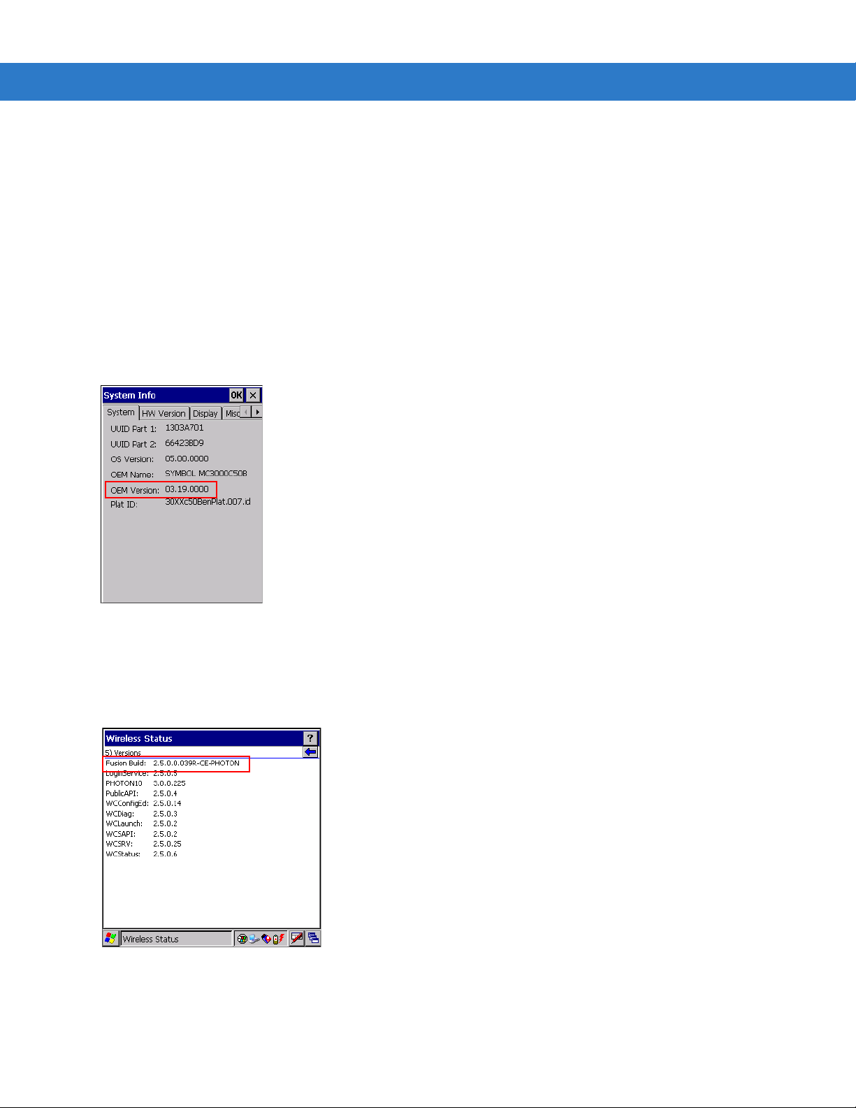
Software Versions
This guide covers various software configurations and references are made to operating system or software
versions for:
•
OEM version
•
Fusion version.
OEM Software
To determine the OEM software version:
Tap
Start > Settings > Control Panel > System Information icon > System tab.
Fusion Software
To determine the Fusion software version:
Tap
Wireless Strength icon > Wireless Status > Versions.
Page 16

xiv MC3000 User Guide
Chapter Descriptions
Topics covered in this guide are as follows:
•
Chapter 1, Getting Started, describes the mobile computer’s physical characteristic s, ho w to ins tall and
charge the batteries, remove and replace the Strap/Door assembly and how to start the mobile computer for
the first time.
•
Chapter 2, Operating the MC3000, provides basic instructions for using the mobile computer and navigating
the mobile computer software.
•
Chapter 3, Using Bluetooth, explains how to perform Bluetooth functionality on the mobile computer.
•
Chapter 4, Accessories, describes the accessories available for the mobile computer and how to use the
accessories to charge the mobile computer.
•
Chapter 5, Maintenance and Troublesho oting, includes instructions on cleaning and storing the mobile
computer, and provides troubleshooting solutions for potential problems during mobile computer operation.
•
Appendix A, Technical Specifications, includes a table listing the technical specifications for the mobile
computer.
•
Appendix B, Keypad Functions/Special Characters, contains special character generation tables.
Notational Conventions
The following conventions are used in this document:
•
The term “mobile computer” refers to the Symbol MC3000.
•
Italics are used to highlight the following:
• Chapters and sections in this and related documents
• Dialog box, window and screen names
• Drop-down list and list box names
• Check box and radio button names
• Icons on a screen.
•
Bold text is used to highlight the following:
• Key names on a keypad
• Button names on a screen.
•
Bullets (•) indicate:
• Action items
• Lists of alternatives
• Lists of required steps that are not necessa rily sequential.
•
Sequential lists (e.g., those that describe step-by-s te p pr oc ed ur e s) ap pe a r as nu m be re d lists.
Page 17

Related Documents and Software
The following items provide more information about the MC3000 mobile computers.
•
MC3000 Series Quick Start Guide, p/n 72-68902-xx
•
MC3090G Quick Start Guide, p/n 72-71347-xx
•
MC3000 Licensing, Patent and Regulatory In fo rm at ion , p/n 72-68903-xx
•
MC3000 Integrator Guide, p/n 72E-68900-xx
•
Symbol Application Guide for Symbol Devices, p/n 72E-68901-xx
•
Microsoft® Applications for Mobile and CE 5.0 User Guide, p/n 72E-78456-xx
•
Symbol Mobility Developer Kit (SMDK) Help File, p/n 72E-38880-03
•
Windows CE Platform SDK for MC3000c50, available at: http://support.symbol.com
•
Symbol Mobility Developer Kit for C (SMDK for C), available at: http://support.symbol.com
•
Device Configuration Package for MC3000 (DCP for MC3000), available at: http://support.symbol.com
About This Guide xv
•
ActiveSync software, available at: http://www.microsoft.com.
For the latest version of this guide and all guides, go to: http://support.symbol.com.
Service Information
If you have a problem with your equipment, contact Motorola Enterprise Mobility support for your region. Contact
information is available at: http://www.symbol.com/contactsupport
When contacting Enterprise Mobility support, please have the following information available:
•
Serial number of the unit
•
Model number or product name
•
Software type and version number
Motorola responds to calls by email, telephone or fax within the time limits set forth in support agreements.
If your problem cannot be solved by Motorola Enterprise Mobility Support, you may need to return your equipment
for servicing and will be given specific directions. Motorola is not responsible for any damages incurred during
shipment if the approved shipping container is not used. Shipping the units improperly can possibly void the
warranty.
If you purchased your Enterprise Mobility business product from a Motorola business partner, contact that business
partner for support.
.
Page 18

xvi MC3000 User Guide
Page 19

Chapter 1 Getting Started
Introduction
This chapter describes the mobile computer physical chara cteristics, how to inst all and charge the ba tteries, how to
remove and replace the Strap/Door Assembly and how to start the mobile computer for the first time.
Unpacking the Mobile Computer
Carefully remove all protective material from around the mobile computer and save the shipping cont ainer for later
storage and shipping. Verify that the equipment listed below is included:
• MC3000 mobile computer
• Strap/Door Assembly, attached to the mobile computer
•Stylus
• Regulatory Guide
• Quick Start Guide.
Depending on the configuration ordered, the mobile computer shipping container or additional shipping container
may include:
• Standard battery (lithium-polymer)
• Extended life battery (lithium-ion)
•Cable(s)
• Power supply
•Cradles.
Inspect the equipment for damage. If any equipment is missing or damaged, contact the Motorola Enterprise
Mobility Support immediately. See Service Information on page xv for contact information.
Page 20

1 - 2 MC3000 User Guide
Accessories
Table 1-1 lists the MC30 00 accessories.
Table 1-1 MC3000 Accessories
Accessory Description
Single Slot Serial/USB Cradle Charges the mobile computer main battery and a spare battery, and
Four Slot Charge Only Cradle Charges up to four mobile computers.
Four Slot Ethernet Cradle Charges up to four mobile computers and provides Ethernet communications.
Four Slot Spare Battery Charger Charges up to four mobile computer spare batteries.
Power Supply Country specific and accessory specific, power supply.
USB Client Charge Cable Provides USB client communication capabilities and charges the mobile
synchronizes the mobile computer with a host computer through eithe r a serial
or USB connection.
computer.
RS232 Charge Cable Provides RS232 communication capabilities and charges the mobile
computer.
O’Neil Printer Cable Provides printer specific communication capabilities (provided by O’Neil).
Zebra Printer Cable Provides printer specific communication capabilities (provided by Zebra).
Monarch Printer Cable Provides printer specific communication capabilities (provided by Monarch).
Single Slot Cradle RS232 Cable Provides serial host communication capabilities and charges the mobile
computer.
Single Slot Cradle USB Cable Provides USB communication capabilities and charges the mobile computer.
MC3000 Universal Battery Charger
Adapter (UBC)
Stylus Performs pen and mouse functions.
Plastic Holster Provides a clip on holder for the mobile computer.
Fabric Holster Provides a soft, clip on holder and a shoulder strap for the mobile computer.
Symbol Mobility Developer Kit for
C (SMDK for C)
Device Configuration Package
(DCP) for MC3000
Adapts the UBC for use with MC3000 batteries.
A development tool used to create native C and C++ applications for all
Symbol mobile computers running the Microsoft Windows CE operating
system. Available at:
A development tool used to create and download hex images that represent
flash partitions to the mobile computer. Available at:
http://support.symbol.com
http://support.symbol.com
.
.
Page 21
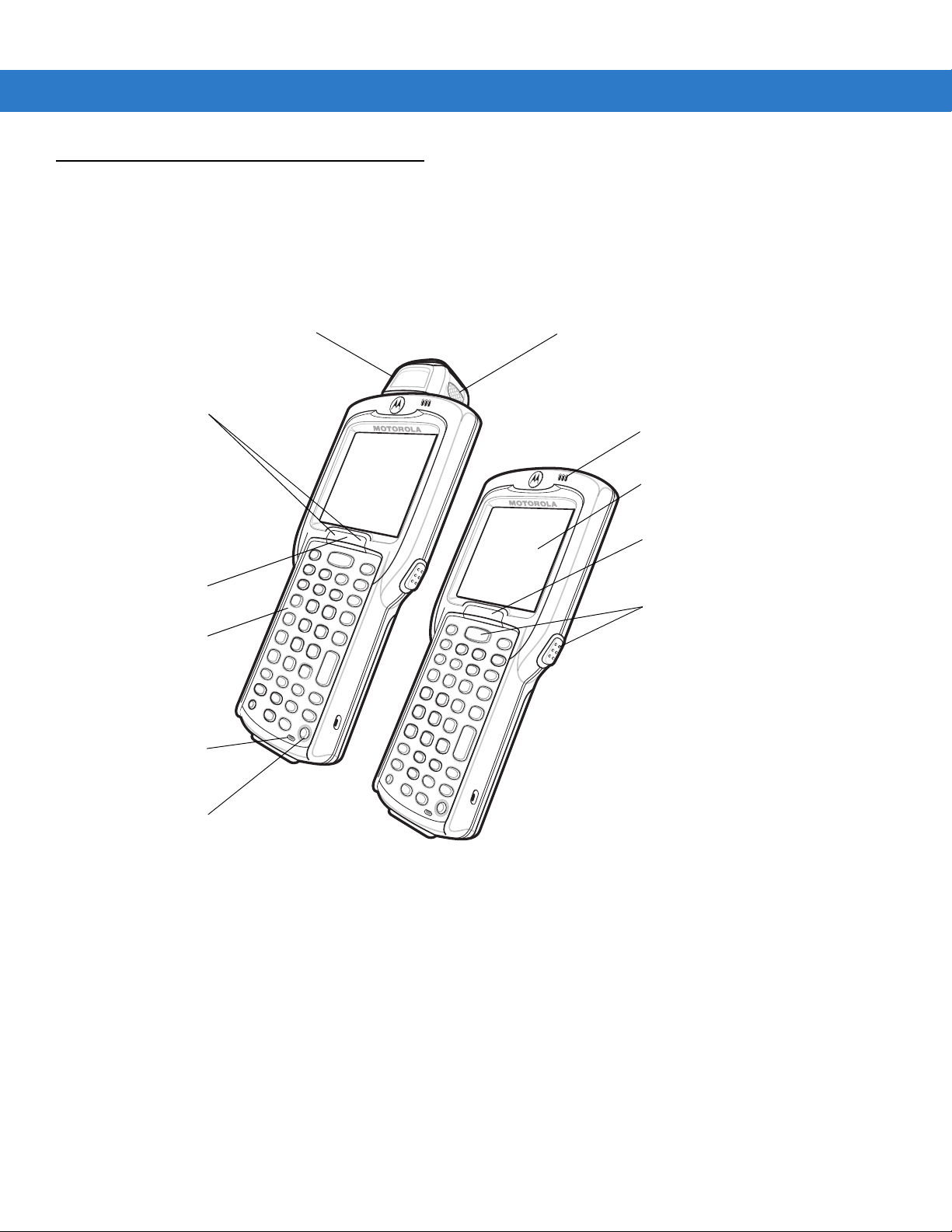
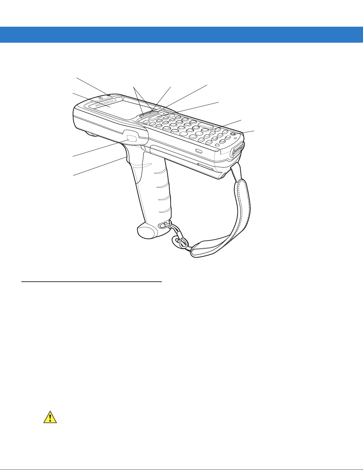
Parts
Keypad
Indicator LED Bar
Display
Scan LED Indicator
(red/green)
Power
Scan Buttons
MC3000R
MC3000S
Rotating Scan
Turret
Beeper or
Receiver
(optional)
Microphone
(optional)
Scan LED
Indicators
(red/green)
Charge LED
Indicator
(amber)
Getting Started 1 - 3
There are three versions of the MC3000 mobile computers, the MC3000 1D/2D Imager (MC3000S or MC3090S),
the MC3000 Laser with Rotating Scan Turret (MC3000R or MC3090R) and the MC3090 Gun (MC3 090G). For
more information on the Rotating Scan Turret, see Figure 1-3 on page 1-4.
Figure 1-1
MC3000 Imager and MC3000 Laser Mobile Computers (Front View)
Page 22
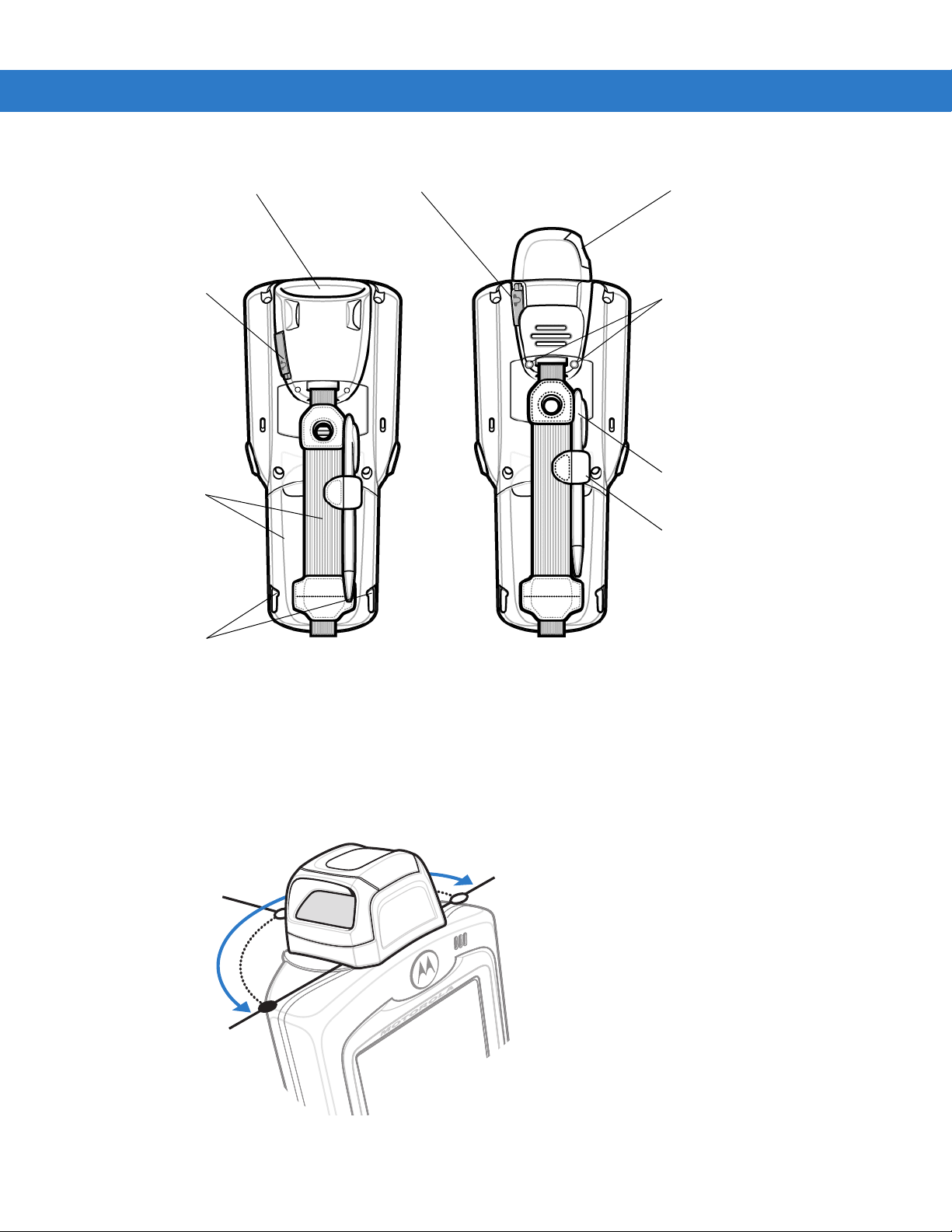
1 - 4 MC3000 User Guide
Strap/Door
Assembly
Scan Window
Stylus
MC3000S
MC3000R
Latches
Strap/Door
Assembly
Screws
Stylus
Holder
Headset Jack
(optional)
Headset Jack
(optional)
Scan Window
Position Stop
Position Stop
Position Stop
Figure 1-2
Rotating Scan Turret
MC3000 Imager and MC3000 Laser Mobile Computers (Back View)
The MC3000R mobile computer features a Rotating Scan Turret with three position stops. This feature offers
greater scanning flexibility.
Figure 1-3
Rotating Scan Turret
Page 23
Getting Started 1 - 5
Keypad
Indicator LED Bar
Display
Power
Scan Button
Beeper
Trigger
Scan LED
Indicators
(red/green)
Charge LED
Indicator
(amber)
Scan LED
Indicator
(red/green)
Mobile Computer Startup
Figure 1-4
MC3090G Mobile Computer
To start using the mobile computer:
• Install the main battery.
• Charge the main battery and the backup battery.
• Start the mobile computer.
Install Main Battery
If the main battery is charged, the mobile computer can be used immediately. If the main battery is not charged,
see Battery Charging on page 1-7. To remove the main battery, see Main Battery Removal on page 1-11.
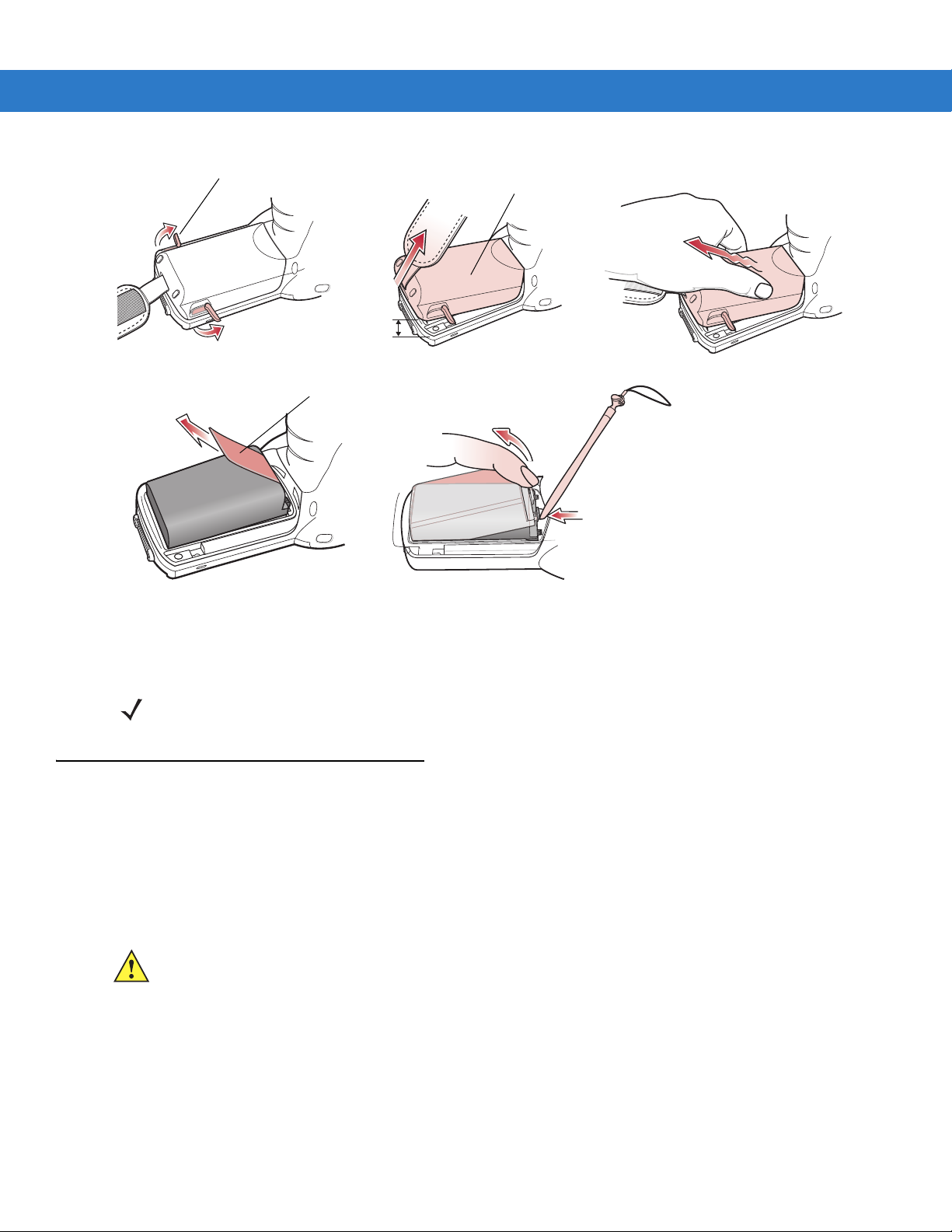
To install the main battery:
1. Rotate the latches to the open position.
CAUTION Do not lift up on the latches when removing the Strap/Door Assembly. Lift up on the Hand Strap only.
2. Pull on the strap to lift the Strap/Door Assembly off, bottom first.
Page 24
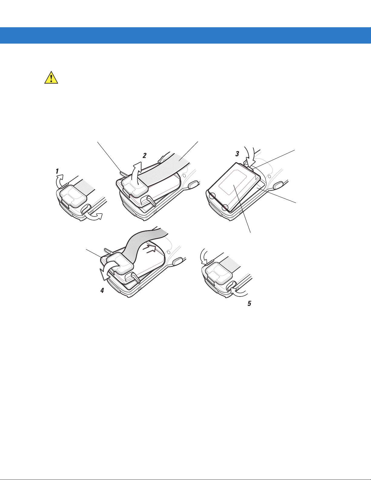
1 - 6 MC3000 User Guide
Battery Clip
Strap/Door
Assembly
Battery
Battery Slot
Hand Strap
Latches
CAUTION On the MC3090G battery, do not remove the battery pull tab. The pull tab is for enabling easy battery
removal from the device.
3. Insert the battery into the slot, bottom first and press the battery gently into the slot. The battery clip locks the
battery into place.
4. With the latches in the open position, replace the Strap/Door Assembly, top first and press to close.
5. Rotate the latches (to the lock position) to lock the Strap/Door Assembly in place.
Figure 1-5
Main Battery Installation (MC3000S/R)
Page 25
Getting Started 1 - 7
5
2
0.5 in.
(12.7 mm)
3
Strap/Door
Assembly
Battery
Hand Strap
Latches
Strap/Door
Assembly
1
Figure 1-6
Main Battery Installation (MC3090G)
Battery Charging
CAUTION Ensure that you follow the guidelines for battery safety described in Battery Safety Guidelines on page 7-1.
Use the mobile computer cradles, cables and spare battery chargers to charge the mobile computer main battery.
The main battery can be charged before insertion into the mobile computer or after it is installed. There are two
main batteries for the MC3000, the Standard Battery and the Extended Life Battery. Either battery can be used, but
the Extended Life Battery requires a different Strap/Door Assembly. Use one of the spare battery chargers to
charge the main battery (out of the mobile computer) or one of the cradles to charge the main battery while it is
installed in the mobile computer.
Before using the mobile computer for the first time, fully charge the main battery until the amber Charge LED
Indicator remains lit (see Table 1-2 on page 1-8 for charge statu s indications). The S tandard Battery fully char ges in
less than four hours and the Extended Life Battery fully charges in less than six hours.
The mobile computer is equipped with a memory backup battery which automatically charges from the main
battery whether or not the mobile computer is operating or is in suspend mode. The memory backup battery retains
data in memory for at least 30 minutes when the mobile computer’s main battery is removed or fully discharged.
When the mobile computer is used for the first time or after the memory backup battery has fully discharged, the
memory backup battery requires approximately 15 hours to fully charge. Do not remove the main battery from the
mobile computer for 15 hours to ensure that the memory backup battery fully charges. If the main battery is
Page 26

1 - 8 MC3000 User Guide
removed from the mobile computer or the main battery is fully discharged, the memory backup battery completely
discharges in several hours.
When the main battery reaches a very low battery state, the combination of main battery and backup battery
retains data in memory for at least 72 hours.
NOTE Do not remove the main battery within the first 15 hours of use. If the main battery is removed before the
backup battery is fully charged, data may be lost.
Batteries must be charged within the 32° to 104° F (0° to +40° C) ambient temperature range.
The following accessories can be used to charge batteries:
• Cradles (and a power supply):
• Single Slot Serial/USB Cradle
• Four Slot Cradles.
• Cables (and a power supply):
• USB Client Charge Cable
• Serial (RS232) Charge Cable.
• Spare Battery Chargers (and a power supply):
• Single Slot Serial/USB Cradle
• Four Slot Spare Battery Charger
• Universal Battery Charger (UBC) Adapter.
To charge the mobile computer using the cradles:
1. Insert the mobile computer into a cradle. See Chapter 4, Accessor ies for accessory setup.
2. The mobile computer starts to charge automatically. The amber Charge LED Indicator indicates the charge
status. See Table 1-2 on page 1-8 for charging indications.
To charge the mobile computer using the cables:
1. Connect the MC3000 Communication/Charge Cable to the appropriate power source and connect to the
mobile computer. See Chapter 4, Accessories for accessory setup.
2. The mobile computer starts to charge automatically. The amber Charge LED Indicator indicates the charge
status. See Table 1- 2 for charging indications.
Table 1-2 Mobile Computer LED Charge Indicators
LED Indication
Off Mobile computer not placed correctly in the cradle; charge cable not connected correctly;
charger is not powered.
Fast Blinking Amber Error in charging; check placement of the mobile computer.
Slow Blinking Amber Mobile computer is charging.
Solid Amber Charging complete.
Note: When the battery is initially inserted in the mobile computer, the amber LED
flashes once if the battery power is low or the battery is not fully inserted.
Page 27

Spare Battery Charging
OR
There are three accessories that can be used to charge a spar e battery:
• Single Slot Serial/USB Cradle
• Four Slot Spare Battery Charger
• UBC Adapter.
To charge a spare battery:
1. Connect the charging accessory to the appropriate power source. See Chapter 4, Accessories for setup
instructions.
2. Insert the spare battery into the spare battery charging slot and gently press down on the battery to ensure
proper contact.
The battery starts to charge automatically. The amber charge LED Indicator lights to indicate the charge status.
See Chapter 4, Accessories for charging indications. The Standard Battery usually fully charges in less than four
hours and the Extended Life Battery usually fully charges in less than six hours.
Getting Started 1 - 9
Stylus
Use the stylus for selecting items and entering information on the screen. The stylus functions as a pen and a
mouse. Tap the touch screen once with the stylus to select options and open menu items.
To remov e th e stylu s, slide th e sty l us out of the stylus holder. To store the stylus, push the stylus ba ck into th e
stylus holder.
Starting the Mobile Computer
On 28, 38 and 48-key keypad configurations, press the Power button to turn on the mobile computer. On 20-key
keypad configurations, simultaneously press the Fn and MENU buttons to turn on the mobile computer. If the
mobile computer does not power on, perform a cold boot. See Resetting the Mobile Computer on page 2-28.
When the mobile computer is powered on for the first time, it initializes. The Splash screen appears for a short
period of time, followed by the Calibration screen.
Figure 1-7
Splash Screen
Page 28

1 - 10 MC3000 User Guide
Calibration Screen Confirm Calibration
Resave Screen
After the calibration procedure is performed the factory settings launch the Demo window. Application specific
shells may provide application specific windows instead of the Demo window. These screens also appear when a
cold boot is performed.
If the mobile computer does not power on, see Resetting the Mobile Computer on page 2-28.
Calibration Screen
Use the Calibration screen to align the touch screen:
1. Remove the stylus from the stylus holder.
2. Carefully press and briefly hold the stylus tip on the center of the Calibration screen target. Repeat the
procedure as the target moves and stops at different locations on the screen. This enters the new calibration
settings.
Figure 1-8
3. Once all of the new calibration settings are input, tap the screen or press the ENTER button to save the new
Calibration Screen
calibration settings. Press ESC to discard the new calibration settings.
Demo Window
The Demo window is the factory default menu. On initial power up (or on a warm or cold boot) the Demo window
appears. These sample/demo applications are intended to be used by application developers as application
development examples. These applications were not developed to support end users. Refer to the Symbol
Application Guide for information about the Demo window applications.
Figure 1-9
Demo Window
Page 29
Waking the Mobile Computer
Battery Clip
Latches
Strap/Door
Assembly
Battery
Hand Strap
The wakeup condition settings are used to define what actions wake up the mobile computer. The settings are
configurable so they are subject to change/update. For more information see, Waking the Mobile Computer on
page 2-29.
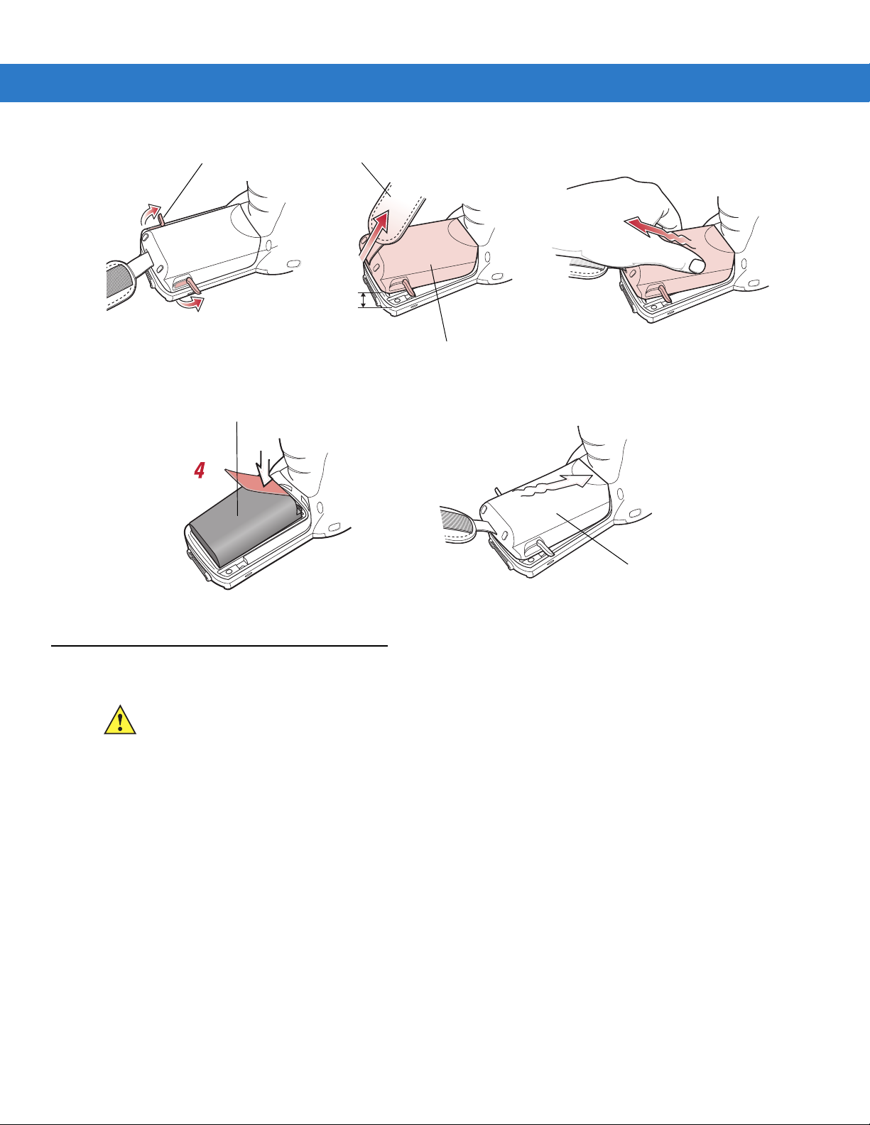
Main Battery Removal
Before removing the main battery, turn off the mobile computer.
To remove the main battery:
1. Rotate the latches to the open position.
CAUTION Do not lift up on the latches when removing the Strap/Door Assembly. Lift up on the Hand Strap only.
2. Lift the Hand Strap to lift the Strap/Door Assembly off, bottom first.
Getting Started 1 - 11
3. Release battery:
a. On the MC3000S/R, release the battery clip (at the top of the battery) and lift the battery out top first.
b. On the MC3090G, pull the battery pull tab to unclip the battery and lift the battery out top first. If the battery
does not have a pull tab, use the stylus to unclip the battery and then lift the battery.
CAUTION On the MC3090G battery, do not remove the battery pull tab. The pull tab is for enabling easy battery
removal from the device.
Figure 1-10
Main Battery Removal (MC3000S/R)
Page 30
1 - 12 MC3000 User Guide
4
4
Strap/Door
Assembly
Latches
Battery Pull Tab
Battery with Pull Tab Battery without Pull T a b
1
Figure 1-11
0.5 in.
(12.7 mm)
Main Battery Removal (MC3090G)
2
3
NOTE The SD card holder is located under the battery. To install the SD card, see Secure Device Card on page 4-12.
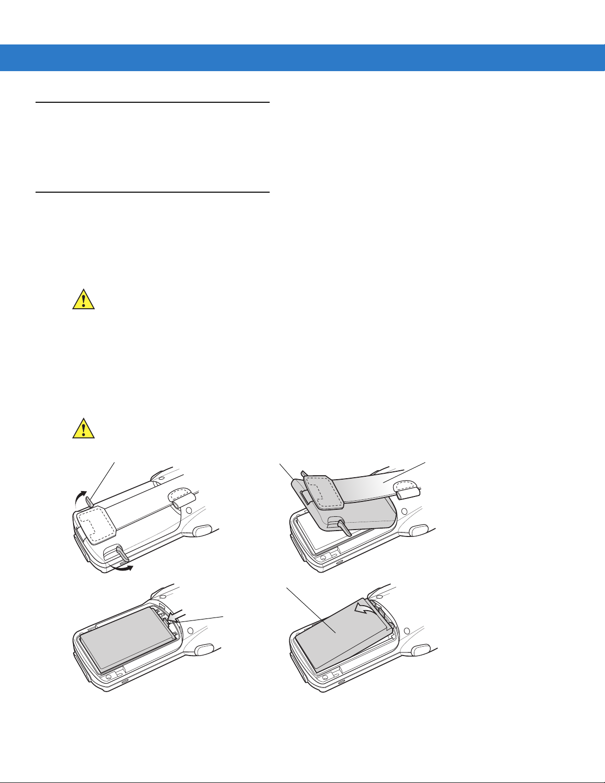
Strap/Door Assembly Removal and Replacement (MC3000S/R)
The Strap/Door Assembly consists of a hand strap and the battery door. There are two versions of this assembly,
one for the Standard Battery and one for the Extended Life Battery. Before removing the Strap/Door Assembly,
press the red Power button to turn off the screen and set the mobile computer to su spend mode.
To remove the Strap/Door Assembly:
1. Rotate the latches to the open position.
CAUTION Do not lift up on the latches when removing the Strap/Door Assembly. Lift up on the Hand Strap only.
2. Lift the Hand Strap to lift the Strap/Door Assembly off, bottom first.
3. Use a #00 Phillips screwdriver to remove the screws.
4. Lift the mounting clip.
5. Slide the mounting clip out of the strap loop.
Reverse the procedure to replace the Strap/Door Assembly.
Page 31

Getting Started 1 - 13
Strap/Door
Assembly
Latches
Screws
#00 Phillips
Screwdriver
Mounting
Clip
Strap Loop
Mounting
Clip
Hand Strap
Figure 1-12
Strap/Door Removal and Replacement (MC3000S/R)
Strap/Door Assembly Removal and Replacement (MC3090G)
The Strap/Door Assembly consist s of a hand strap and the battery door. Before removing the Strap/Door Assembly,
press the red Power button to turn off the screen and set the mobile computer to su spend mode.
To remove the Strap/Door Assembly:
1. Slip the button through the loop.
2. Remove loop section from handle.
3. Rotate the latches to the open position.
CAUTION Do not lift up on the latches when removing the Strap/Door Assembly. Lift up on the Hand Strap only.
4. Lift the Hand Strap to lift the Strap/Door Assembly off, bottom first.
Reverse the procedure to replace the Strap/Door Assembly.
Page 32

1 - 14 MC3000 User Guide
Strap/Door
Assembly
Latches
Button
Loop
Figure 1-13
Turning Off the Radios
On Device with CE 5.0 (OEM Version 01.15 or lower)
NOTE To determine the operating system OEM version, see Configurations on page xii.
WLAN Radio
To turn off the WLAN radio:
1. Tap Start > Settings > Control Panel > Power icon > PwrDevices tab.
2. In the text box, scroll down until WLP1: displays.
3. Select WLP1:. WLP1: displays in the text box at the top of the window.
4. In the drop-down list box, select D4.
5. Tap Set.
0.5 in.
(12.7 mm)
Strap/Door Removal and Replacement (MC3090G)
To turn on the radio:
1. Tap Start > Settings > Control Panel > Power icon > PwrDevices tab.
2. In the text box, scroll down until WLP1: displays.
Page 33

Getting Started 1 - 15
Bluetooth Icon
Wireless Connection Status Icon
Bluetooth Icon
3. Select WLP1:. WLP1: displays in the text box at the top of the window.
4. In the drop-down list box, select D0.
5. Tap Set.
Bluetooth Radio
To turn off the Bluetooth radio, tap Bluetooth icon in the task tray and select Disable Bluetooth.
Figure 1-14
To turn on the Bluetooth radio, tap
Bluetooth Icon
Bluetooth icon in the task tray and select Enable Bluetooth.
On Device with CE 5.0 (OEM Version 01.16 or higher)
NOTE To determine the operating system OEM version, see Configurations on page xii.
WLAN Radio
To turn off the WLAN radio tap the Wireless Connection Status icon on the task tray and select Disable Radio. A red
X appears across the icon indicating that the radio is disabled (off).
Figure 1-15
To turn the radio back on, tap the
X disappears from the icon indicating that the radio is enabled (on).
Bluetooth Radio
Wireless Connection Status Icon
Wireless Connection St atu s icon on the t ask tray and select Enable Radio. The red
To turn off the Bluetooth radio, tap Bluetooth icon in the task tray and select Disable Bluetooth.
Figure 1-16
To turn on the Bluetooth radio, tap
Bluetooth Icon
Bluetooth icon in the task tray and select Enable Bluetooth.
Page 34

1 - 16 MC3000 User Guide
Page 35

Chapter 2 Operating the MC3000
Introduction
This chapter provides basic instructions for using the mobile computer and navigating the mobile compute r
software.
Power Button
Press the red Power button to toggle the mobile computer between suspend and resume. When the screen is off
the mobile computer is in suspend mode and when the screen is on the mobile computer is on.
Keypads
The mobile computer is available with the following keypad configurations:
• 20-key mechanical keypad
• 28-key keypad
• 38-key keypad
• 48-key keypad.
NOTE For information about using the soft keyboard input panel. For more information, see Entering Information
Using the Keyboard Input Panel on page 2-19.
Page 36
2 - 2 MC3000 User Guide
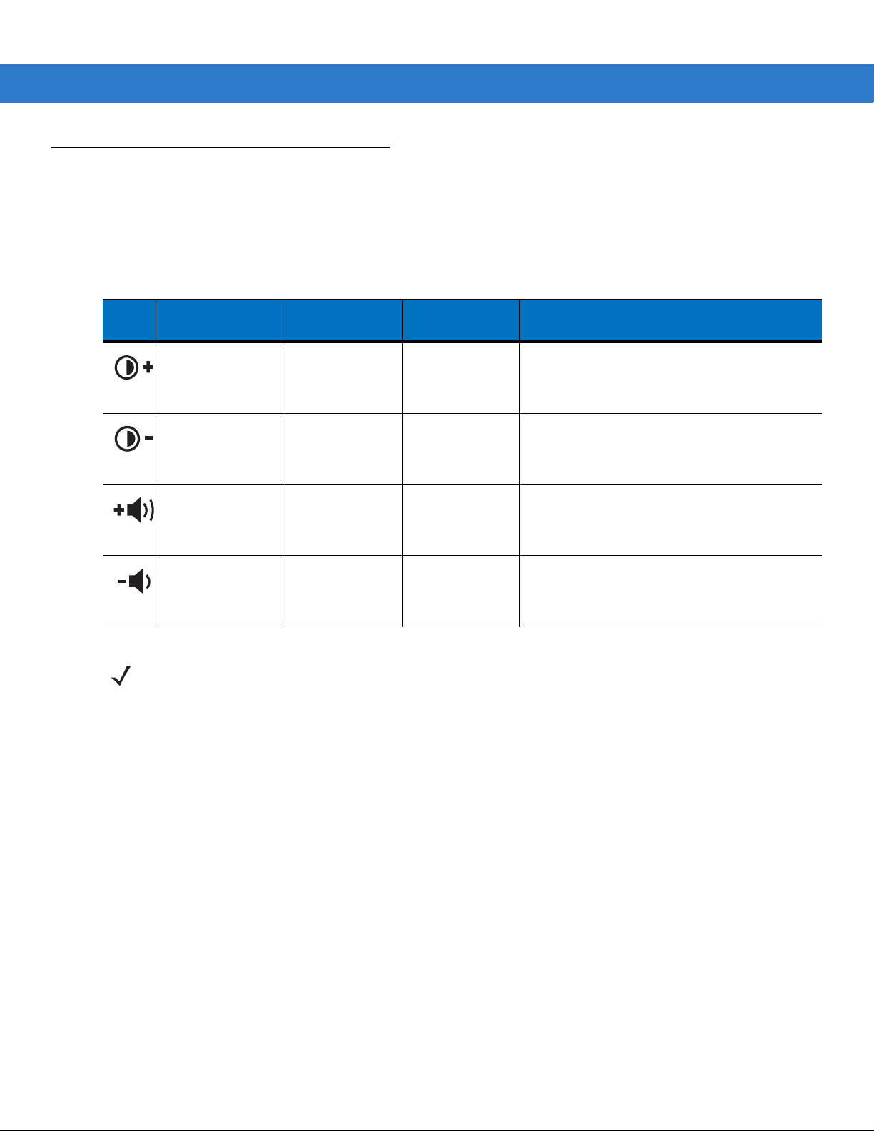
Keypad Special Functions
The keypad special functions are color coded on the keypads. For example, on the 38-key keypad, the display
contrast icon is blue indicating that the blue function key must be selected first along with the F6 key, to increase
the display contrast.
Table 2-1 Keypad Special Functions
Icon
28-Key
Keystrokes
Blue function key
and
period
.
Blue function key
and
BKSP
.
Blue function key
and the up arrow.
Blue function key
and down arrow.
NOTE Mobile computers with color screens do not have contrast settings.
38-Key
Keystrokes
Blue function
key and
Blue function
key and
Blue function
key and
Blue function
key and
F6
F9
F7
F10
48-Key
Keystrokes
Blue function
key and
Blue function
key and
Blue function
key and
Blue function
key and
N
S
R
W
Special Function
Increases display contrast setting, darkens the
display (on monochrome units only).
Decreases display contrast setting, lightens the
display (on monochrome units only).
Increases scan decode beeper volume.
Decreases scan decode beeper volume.
Page 37
Operating the MC3000 2 - 3
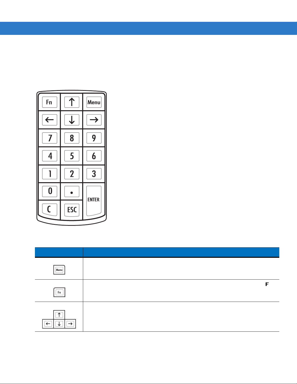
20-Key Mechanical Keypad
The 20-key mechanical keypad contains a Power button, application keys, scroll keys and function keys. The
keypad is color-coded to indicate the alternate function key (blue) values. Note, that keypad functions can be
changed by an application so the mobile computer keypad may not function as d escribed. See Table 2-4 on page
2-8 for key and button descriptions.
Figure 2-1 20-Key Mechanical Keypad
Table 2-2 20-Key Mechanical Keypad Descriptions
Key Description
Menu Produces the lower case alphabetic f.
Turns the mobile computer on and off when simultaneously pressed with the down arrow
key. See
Fn
Arrow keys Moves up and down from one item to another.
Press and release the blue
icon appears on the taskbar. Press and release the blue
default keypad functions.
Resetting the Mobile Computer on page 2-28
FUNC
key to activate the keypad alternate functions. The
for warm and cold boot procedures.
FUNC
key again to return to the
Page 38
2 - 4 MC3000 User Guide
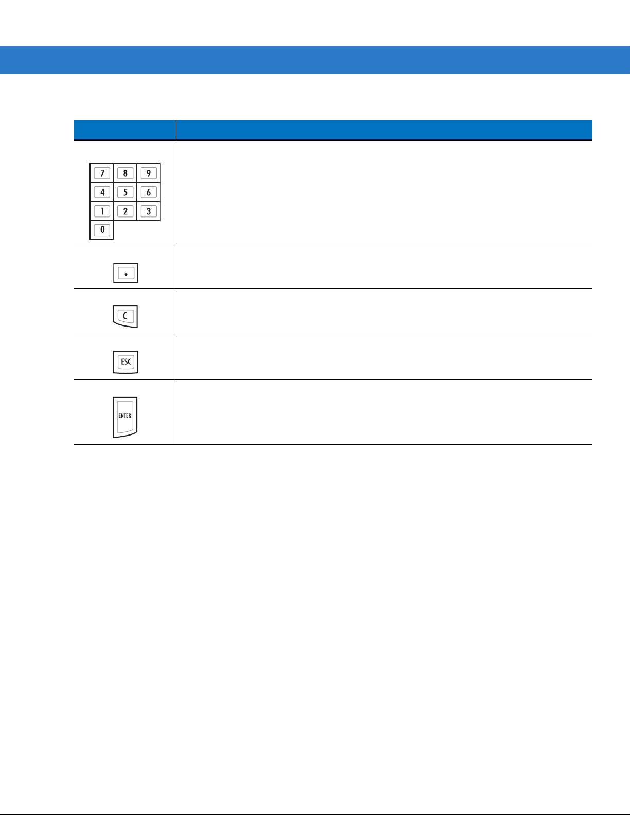
Table 2-2 20-Key Mechanical Keypad Descriptions (Continued)
Key Description
Numeric keys Produces 0 - 9 numeric characters.
period Produces a (.) period.
C Produces a backspace.
ESC Exits the current operation.
ENTER Executes a selected item or function.
Produces a TAB character when pressed after the
Fn
key.
Page 39

Operating the MC3000 2 - 5
28-Key Keypad
The 28-key keypad contains a Power button, application keys, scroll keys and function keys. The keypad is
color-coded to indicate the alternate function key (blue) values a nd the alternate ALPHA key (orange) values. Note
that keypad functions can be changed by an application so the mobile computer keypad may not function as
described. See Table 2-3 on page 2-5 for key and button descriptions and Table 2-1 on page 2-2 for the keypad
special functions.
Figure 2-2 28-Key Keypad
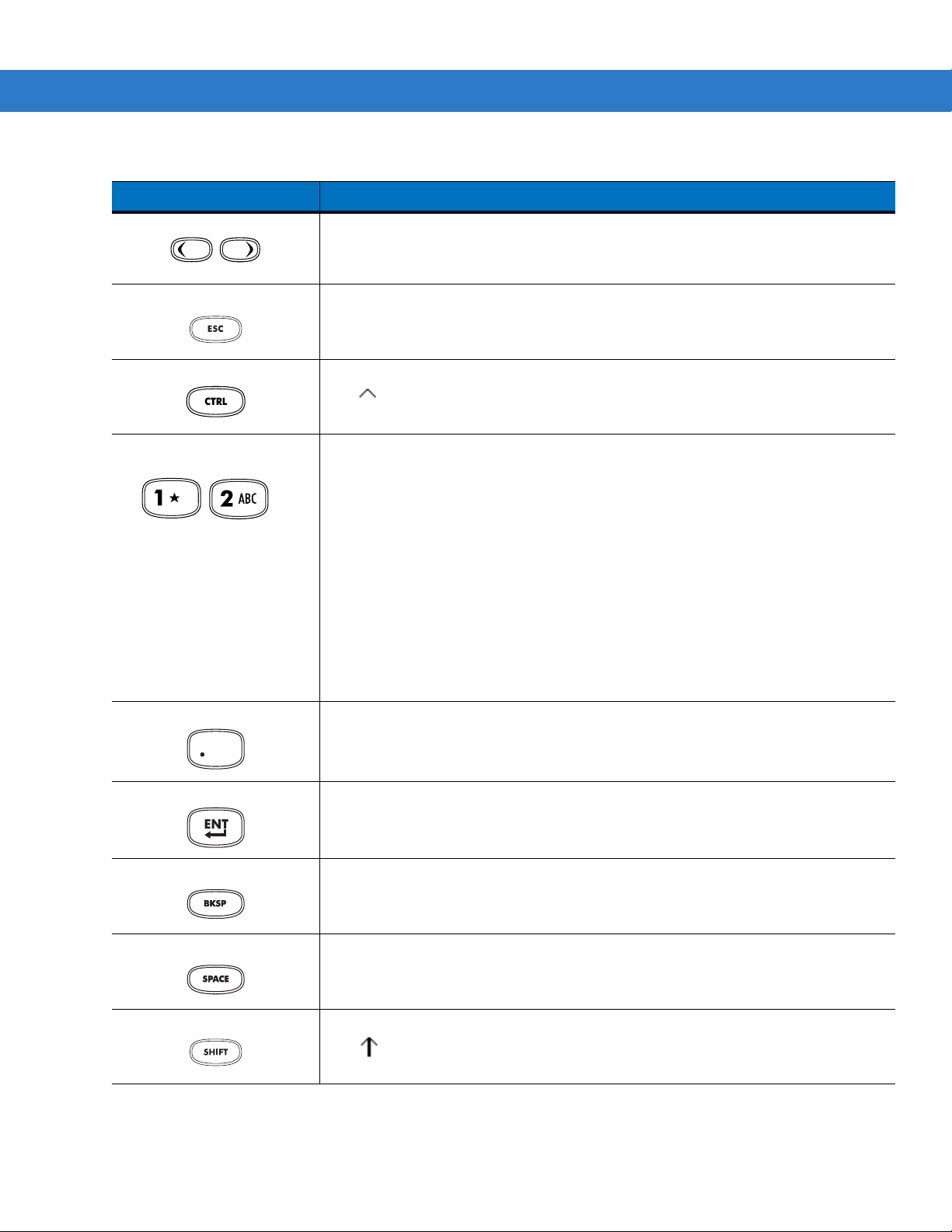
Table 2-3 28-Key Descriptions
Key Description
Power (red) Powers the mobile computer screen on and off (resume and suspend).
Green Circle Programmable application function key by default.
Red Circle Programmable application function key by default.
Scan (yellow) Used in scanning applications, press to scan a bar code. This key has the same
function as activating the side mounted scan buttons.
Scroll Up and Down Moves up and down from one item to another. Increases/decreases specified
values.
Page 40
2 - 6 MC3000 User Guide
Table 2-3 28-Key Descriptions (Continued)
Key Description
Scroll Left and Right Moves left and right from one item to another. Increases/decreases specified values.
Produces a
pressed.
TAB
when the blue
FUNC
key is activated and the right arrow key is
ESC Produces the
CTRL Press and release the CTRL key to activate the keypad alternate CTRL functions.
The icon appears on the taskbar. Press and release the CTRL key again to
return to the default keypad functions.
Numeric/Alpha/Special
Function
Period/Decimal Point Produces a period for alpha entries and a decimal point for numeric entries by
Numeric, alpha or special function keys. Numeric by default.
Produces a special function when the blue
Produces alpha values when the orange
In Alpha state, produces the lower case alphabetic characters on the key. Each key
press produces the next alphabetic character in sequence. For example, press and
release the
and release the
letter ‘i’.
When the
on the key are produced. For example, p ress and release the
hold the
and release the
three times to produce the letter ‘I’.
default.
Produces the
ESC
function by default.
FUNC
key is activated.
ALPHA
ALPHA
SHIFT
SHIFT
key and then press the 4 key once to produce the letter ‘g’; press
ALPHA
key is pressed in Alpha state, the upper case alphabetic characters
key and then press the 4 key once to produce the letter ‘G’; press
ALPHA
F10
key and then press the 4 key three times to produce the
key , press and hold the
function when the blue
FUNC
key is activated.
ALPHA
SHIFT
key and then press the 4 key
key is activated.
key , press and
Enter Executes a selected item or function.
BKSP
BKSP
SPACE
Shift Press and release the
, backspace function by default.
SP ACE
The icon appears on the taskbar. Press and release the
return to the default keypad functions.
, space function by default.
SHIFT
key to activate the keypad alternate SHIFT functions.
SHIFT
key again to
Page 41
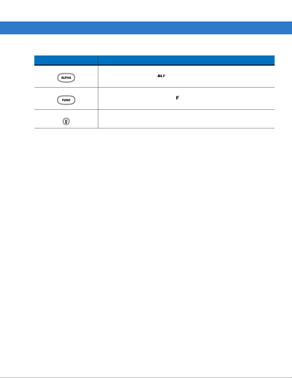
Table 2-3 28-Key Descriptions (Continued)
Key Description
Operating the MC3000 2 - 7
ALPHA (orange) Press the orange
the keypad in orange). The icon appears on the taskbar. Press and release the
orange
FUNC (blue) Press and release the blue
(shown on the keypad in blue). The icon appears on the taskbar. Press and
release the blue
Display backlight
Toggles the display backlight on and off.
ALPHA
ALPHA
key again to return to the default keypad functions.
FUNC
key to access the alternate
key again to return to the default keypad functions.
ALPHA
FUNC
key to activate the keypad alternate functions
characters (shown on
Page 42

2 - 8 MC3000 User Guide
38-Key Keypad
The 38-key keypad contains a Power button, application keys, scroll keys and function keys. The keypad is
color-coded to indicate the alternate function key (blue) values. Note that keypad functions can be changed by an
application so the mobile computer keypad may not function as described. See Tabl e 2- 4 on page 2-8 for key and
button descriptions and Table 2-1 on page 2-2 for the keypad special functions.
Figure 2-3 38-Key Keypad
Table 2-4 38-Key Descriptions
Key Description
Power (red) Powers the mobile computer screen on and off (resume and suspend).
Green Circle Programmable application function key by default.
Red Circle Programmable application function key.
Page 43

Table 2-4 38-Key Descriptions (Continued)
...
Key Description
Scan (yellow) Used in scanning applications, press to scan a bar code.
Scroll Left and Right Moves left and right from one item to another by default.
Produces a
pressed.
Scroll Up and Down Moves up and down from one item to another by default.
TAB
when the blue
FUNC
key is activated and the right arrow key is
Operating the MC3000 2 - 9
ALPHA (orange) Press the orange
keypad in orange). The icon appears on the taskbar. Press and release the or ange
ALPHA
CTRL Press and release the
default keypad functions.
CLEAR Clears inputs.
FUNC (blue) Press and release the blue
on the keypad in blue). The icon appears on the taskbar. Press and release the blue
FUNC
Numeric/Alpha/Special
Function
BKSP/SPACE
SHIFT Press and release the
Press for the default numeric value.
Produces alpha values when the orange
BKSP
Produces the
default keypad functions.
key again to return to the default keypad functions.
icon appears on the taskbar. Press and release the
key again to return to the default keypad functions.
, backspace function by default.
icon appears on the taskbar. Press and release the
ALPHA
SPACE
key to access the alternate
CTRL
function when the orange
SHIFT
ALPHA
key to activate the keypad alternate
FUNC
key to activate the keypad alternate functions (shown
ALPHA
key to activate the keypad alternate
key is activated.
ALPHA
characters (shown on the
CTRL
functions. The
CTRL
key again to return to the
key is activated.
SHIFT
functions. The
SHIFT
key again to return to the
Enter Executes a selected item or function.
Period/Decimal Point Produces a period for alpha entries and a decimal point for numeric entries.
Produces alpha values when the orange
ALPHA
key is activated.
Page 44

2 - 10 MC3000 User Guide
...
Table 2-4 38-Key Descriptions (Continued)
Key Description
Comma Produces a comma by default.
Special Function/Alpha Special function by default or when the blue
Display backlight Toggles the display backlight on and off.
Produces alpha values when the orange
Produces alpha values when the orange
ALPHA
FUNC
ALPHA
key is activated.
key is activated.
key is activated.
Page 45

Operating the MC3000 2 - 11
48-Key Keypad
The 48-key keypad contains a Power button, application keys, scroll keys and function keys. The keypad is
color-coded to indicate the alternate function key (blue) values. Note, that keypad functions can be changed by an
application so the mobile computer keypad may not function as described. See Tabl e 2- 4 on page 2-8 for key and
button descriptions and Table 2-1 on page 2-2 for the keypad special functions.
Figure 2-4 48-Key Keypad
Table 2-5 48-Key Descriptions
Key Description
Power (red) Powers the mobile computer screen on and off (resume and suspend).
Green Circle Unassigned application function key by default.
Red Circle Unassigned application function key.
Scan (yellow) Scan key, used for scanning applications.
Orange
Press the orange key to access the alternate navigation and selection functions. The
icon appears on the taskbar. Press and release the orange key again to return to the
default keypad functions.
Page 46

2 - 12 MC3000 User Guide
...
ALT
...
Table 2-5 48-Key Descriptions (Continued)
Key Description
Numeric/Scroll/Select Numeric, scroll, select keys. Numeric by default.
With the orange key activated, the
2, 4, 6
key produces a select function. With the
and
9
produces the
TAB
function.
, and 8 keys produce scroll functions and the 5
FUNC
key activated, 7 produces the
ESC
function
Shift Press and release the
icon appears on the taskbar. Press and release the
SHIFT
key to activate the keypad alternate
SHIFT
key again to return to the
SHIFT
functions. The
default keypad functions.
Enter Executes a selected item or function.
BKSP/SPACE
BKSP
, backspace function by default.
Produces the
SPACE
function when the blue
FUNC
key is activated.
Period/Decimal Point Produces a period for alpha entries and a decimal point for numeric entries.
Control
Press and release the
CTRL
key to activate the keypad alterna te
icon appears on the taskbar. Press and release the
CTRL
functions. The
CTRL
key again to return to the default
keypad functions.
Press and release the blue
functions. The icon appears on the taskbar. Press and release the
FUNC
key and then the
CTRL
key to activate the
CTRL
times to return to the default keypad functions.
Alpha/Special
Function
Alpha by default.
Special function by default when the blue
FUNC
key is activated.
ALT
key two
FUNC (blue) Press and release the blue
FUNC
function key to activate the keypad alternate functions
(shown on the keypad in blue). The icon appears on the taskbar . Press and release the
blue
FUNC
function key again to return to the default keypad functions.
Display Backlight Toggles the display backlight on and off.
Page 47

Demo Window
Test Applications WindowDemo Window
Windows CE .NET 5.0 Core DesktopWindows CE .NET 5.0 Professional Desktop
On initial power up (or on a warm or cold boot) the Demo window appears. This window links to the Test
Applications window and the two windows provide the sample/demo applications. The sample/demo applications
are intended to be used by application developers as applica tion develop ment ex amples. T hese applica tions were
not developed to support end users. Refer to th e Symbol Application Guide for the Demo window applications.
Operating the MC3000 2 - 13
Figure 2-5 Demo Window
NOTE The Demo window is the factory default launcher menu. Application specific shells may vary.
Desktop Window
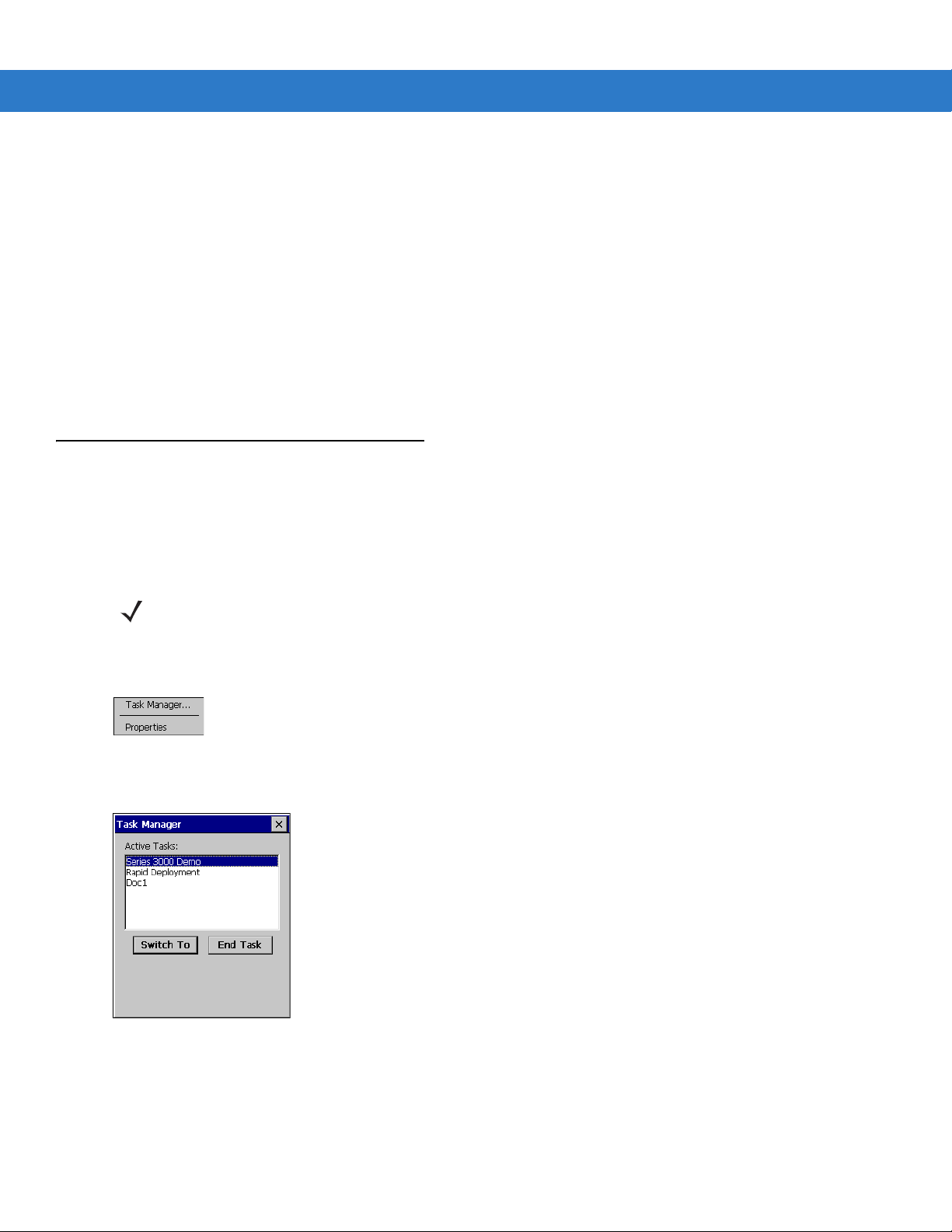
To access the desktop tap the Exit icon on the Demo window or tap the Desktop Display button. See Figure 2-7 on
page 2-14 for the Desktop Display button location. The desktop displays the applications available with the
Windows CE .NET 5.0 Professional and with the Windows CE .NET 5.0 Core configurations. For information on
using the Microsoft
72E-68197-xx.
®
Applications refer to the Microsoft® Applications User Guide for Symbol Devices, p/n
Figure 2-6 Desktop Window
Page 48
2 - 14 MC3000 User Guide
Start Button
Open Programs and Status Icons
Keyboard Input Panel Button
Desktop Display Button
Window Title
Scroll Status Icons
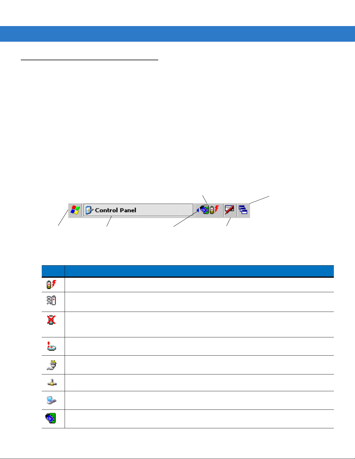
Taskbar
The taskbar (at the bottom of the screen) displays the Start button, active programs, battery status and
communication status. The taskbar icons are described in Table 2-6. The taskbar icons display the function status,
indicate what programs are active and indicate the battery charge status. The Taskbar buttons are used to access
menus, select/deselect functions or to change display windows.
• Status Icons: The status icons indicate the function key status. If the FUNC, SHIFT, CTRL, ALT or ALPHA
functions are active the appropriate status icon is displayed.
• Active Programs Icons: The active applications icons are displayed on the t askbar. If more than one program
is active, icons can be used to toggle between the open programs (applications). Tap on a taskbar application
to maximize the application.
• AC Power/Battery Status Icons: The AC Power/Battery Status icons are shown in the taskbar to indicate the
present power supply status of the mobile computer. The main battery status icons provide the battery status
in 10% increments from 10% to 100%. The backup batte ry low icon in dicates that th e backup batter y char ge
is low. See Battery Charging on page 1-7 for backup battery charging instructions.
Figure 2-7 Taskbar
Table 2-6 Taskbar Icons
Icon Description
Indicates that the battery is charging.
Indicates that the battery is fully charged (100% charged).
The battery status icons provide the battery status in 10% increments from 10% to 100%.
Indicates that communication with the smart battery has not been established. After a mobile computer
reset, this icon may be displayed for up to 30 seconds. See,
additional information.
Indicates that the backup battery is low.
Indicates that the battery is fully charged and the mobile computer is running on external power.
Indicates IP status. Only displays when the mobile computer is in emulation mode.
Indicates that the ActiveSync application is running.
Indicates that the wireless application radio is connected to a wireless LAN network with excellent signal
strength. See
Table 2-11 on page 2-30
for all of the signal strength icons.
Battery Unknown Icon on page 2-15
for
Page 49
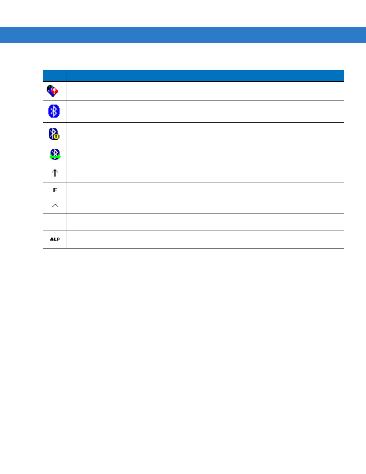
Table 2-6 Taskbar Icons (Continued)
ALT
Icon Description
Indicates that the wireless application radio is not connected to a wireless LAN network.
The Bluetooth Enabled icon appears in the task tray and indicates that the Bluetooth radio is on.
The Bluetooth Disabled icon appears in the task tray and indicates that the Bluetooth radio is off.
The Bluetooth Communication icon appears in the task tray and indicates that the mobile computer is
communicating with another Bluetooth device.
Operating the MC3000 2 - 15
Indicates that the
Indicates that the
Indicates that the
Indicates that the
Indicates that the mobile computer is in
SHIFT
FUNC
CTRL
ALT
button function is selected.
button function is selected.
button function is selected.
character selection is selected.
ALPHA
button mode is selected.
Battery Unknown Icon
The Battery Unknown icon displays when communication with the smart battery has not been established. As part
of normal operation this icon may be displayed for 30 seconds following a mobile computer reset.
If the icon displays beyond this 30 second period:
1. Remove and re-seat the battery.
2. If after re-seating the battery, the icon remains, warm boot the mobile computer.
3. If after warm booting the mobile computer, the icon remains, then cold boot the mobile computer.
4. If after cold booting the mobile computer, the icon remains, install a new (tested and working) battery.
5. If the icon remains, return the mobile computer for servicing.
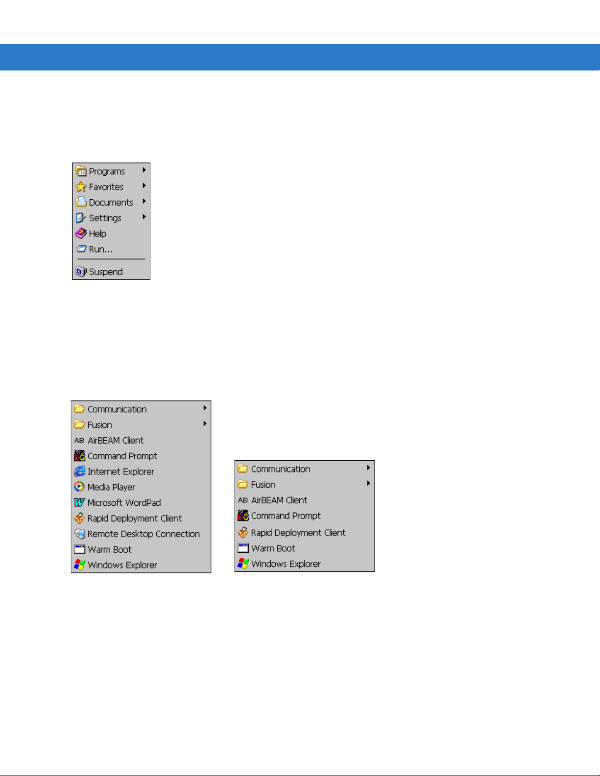
Start Button
Tap th e Start button to launch the Start menu.
• Programs: Use to access available programs.
• Favorites: Displays files in Favorites directory.
• Documents: Displays files in Documents directory.
• Settings: Accesses the Control Panel, the Network and Dial-up Connections and the Taskbar and Start
menu.
Page 50
2 - 16 MC3000 User Guide
Windows CE .NET 5.0 Professional
Windows CE .NET 5.0 Core
• Help: Accesses the Windows CE Help. Not available on mobile computers running Windows CE .NET 5.0
Core.
• Run . . . : Runs a program or application.
• Suspend: Places the mobile computer in the suspend state.
Figure 2-8 Start Menu
Programs Menu
From the Start menu, tap Programs to launch the Programs menu. The programs provided with Windows CE .NET
5.0 Professional and Windows CE .NET 5.0 Core are displayed in the Programs menu. Refer to the Symbol
Application Guide, p/n 72-68901-xx and the Microsoft
72E-68197-xx for application information.
®
Applications User Guide for Symbol Devices, p/n
Figure 2-9 Programs Menu
Keyboard Input Panel Button
Use the Keyboard Input Panel as an alternate input device. For more information, see Entering Information Using
the Keyboard Input Panel on page 2-19.
Desktop Display Button
Use the Desktop Display button to minimize all open programs and display the desktop.
Page 51
Windows CE .NET 5.0 Core desktop functions include:
• My Computer: Double-tap the icon to open My Computer.
• Recycle Bin: Deleted files remain in the recycle bin until the recycle bin is emptied. Once emptied the files
cannot be retrieved.
Windows CE .NET 5.0 Professional desktop functions include:
• My Computer: Double-tap the icon to open My Computer.
• Recycle Bin: Deleted files remain in the recycle bin until the recycle bin is emptied. Once emptied the files
cannot be retrieved.
• Remote Desktop Connection: Tap the Remote Desktop Connection icon to access the Remote Desktop
Connection window.
Task Manager and Properties
Use the Task Manager to control an application’s use and use the Properties functions to set display and clock
options.
Operating the MC3000 2 - 17
Task Manager
NOTE The 20-key mechanical keypad does not contain a CTRL key.
1. Select FUNC - CTRL, (to activate the ALT state) and tap on the taskbar to display the Task Manager,
Properties Selection menu.
Figure 2-10 Task Manager, Properties Selection Menu
2. Tap Task Manager to display the Task Manager window.
Figure 2-11 Task Manager Window
3. Tap a task in the Active Ta sks list and tap Switch To to make that task the primary task, or tap End T ask to end
the selected task.
4. Tap X to exit the Task Manager window.
Page 52
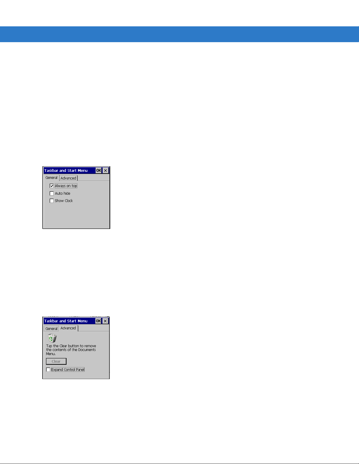
2 - 18 MC3000 User Guide
Properties
1. Tap Start > Control Panel > Taskbar and Start Menu ... . The Task Manager, Properties window displays, see
Figure 2-10 on page 2-17.
2. Tap Properties to display the Taskbar and Start Menu, General tab.
3. This menu provides taskbar options:
• Check the Always on Top checkbox to keep the taskbar on top of all other windows.
• Check the AutoHide checkbox to make the taskbar disappear, touch the bottom of the display to make the
taskbar return.
• Check the Show Clock checkbox to display the clock on the taskbar.
4. Tap OK to save the settings and exit the window.
Figure 2-12 Taskbar and Start Menu, General Tab
Advanced Tab
1. Tap th e Advanced tab to enter the Taskbar and Start Menu, Advanced tab.
2. Tap th e Clear button to delete all of the documents listed in the Start > Documents entry, see Start Button on
page 2-15. Typically this list is empty, but if there were documents in the list the Clear button would delete
them.
3. Tap the Expand Control Panel checkbox to display the entire contents of the MS control p anel in list form, rather
than icons.
Figure 2-13 Taskbar and Start Menu, Advanced Tab
4. Tap OK to save the settings and exit the window.
Page 53

Entering Information
To enter information:
• Use the keypad.
• Use the keyboard input panel (soft keyboard) to enter text.
• Scan bar code data into data fields.
• Use Microsoft
computer. For more information on ActiveSync, refer to the MC3000 Integrator Guide.
Entering Information Using Keypad
The 28, 38 and 48-key alphanumeric keypads produce the 2 6-characte r alphabet (A - Z), nu mbers (0 - 9) , functio n
keys and assorted characters. The keypads default characters/functions are printed black or white, the ALPHA
character/functions are printed orange and the FUNC character/functions are printed blue. The 20-key mechanical
keypad produces numbers (0 - 9) and function key and various characters. See Keypads on page 2-1 for keypad
configurations, see Table 2-1 on page 2-2 for keypad special functions and see Table B-1 on page B-2 for the
special character generation.
®
ActiveSync® to synchronize or copy information from the host computer to the mobile
Operating the MC3000 2 - 19
Entering Information Using the Keyboard Input Panel
Use the keyboard input panel (soft keyboard) to enter information in any program. To launch the keyboard input
panel, tap the button on the taskbar. Tap a key to enter the value. Tap the keyboard input panel button to
display or to hide the keyboard input panel.
Figure 2-14 Keyboard Input Panel
Entering Data via the Bar Code Scanner
The sample bar code scanner application scans data into data fields in the same way data is entered via the
keypad.
Page 54
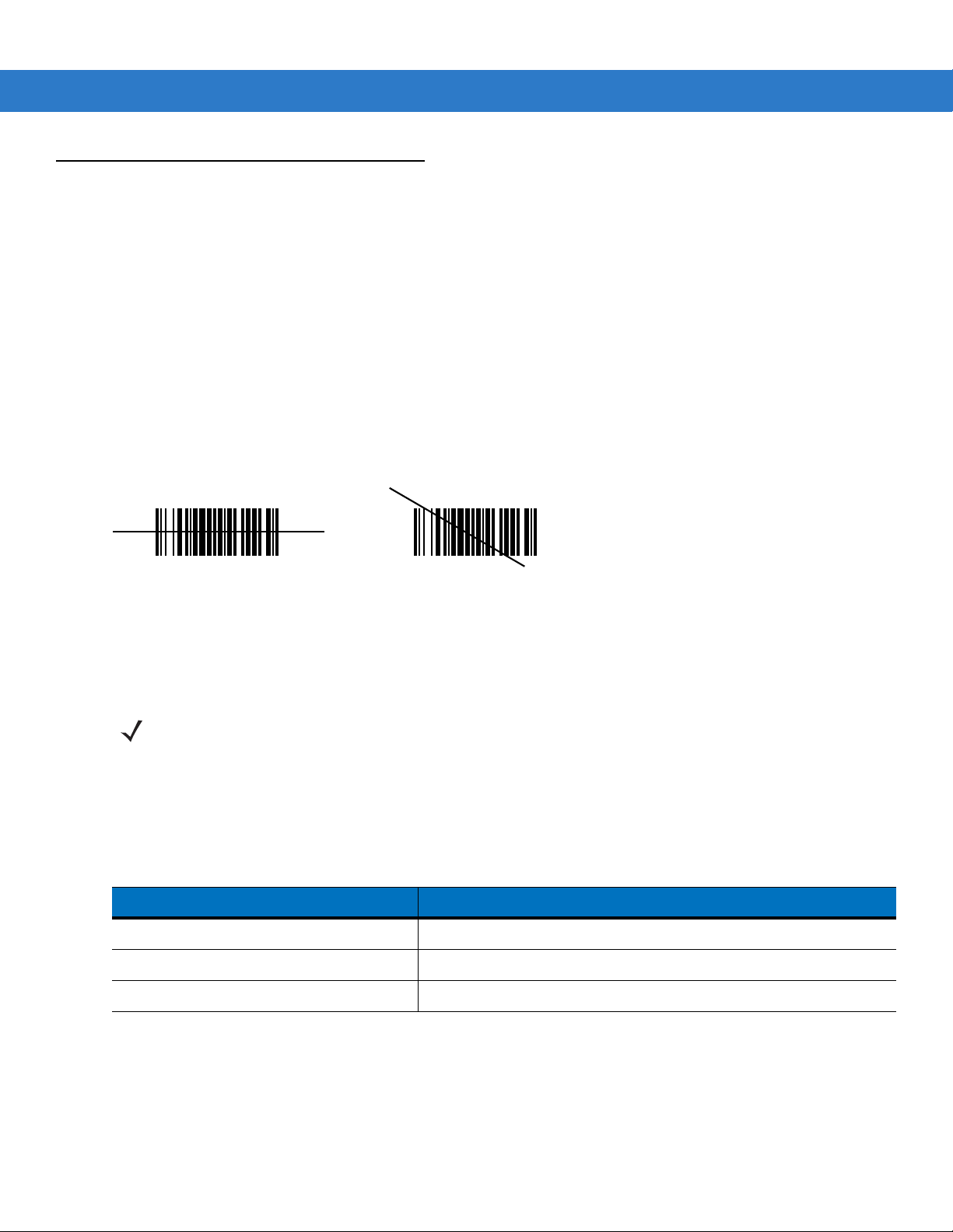
2 - 20 MC3000 User Guide
Wrong
Right
Data Capture
The mobile computer has an integrated scanner or imager that collects data by scanning bar codes.
Laser Scanning
To scan bar codes with the mobile computer:
1. Ensure that the mobile computer is loaded with a scanning application.
2. If the mobile computer is equipped with a rotating head, adjust the head prior to scanning.
3. Aim the scan window at the bar code.
4. Press the scan button or trigger. Ensure the red scan beam covers the entire bar code. The Scan LED
Indicators illuminate red to indicate that the laser is on. The Scan LED Indicators illuminate green and a beep
sounds to indicate a successful decode.
Figure 2-15 Laser Aiming
Optimal scanning distance varies with bar code density and scanner optics.
• Hold the scanner farther away for larger symbols.
• Move the scanner closer for symbols with bars that are close together.
NOTE Scanning procedures depend on the application and mobile computer configuration. An application may use
different scanning procedures from the one listed above.
Scan LED Indicators
The red/green Scan LED Indicators (located in the Indicator LED Bar and in the rotating turret) indicates the scan
status. For the location of the Scan LED Indicators see, Figure 1-1 on page 1-3.
Table 2-7 Scan LED Indicators
LED Status Indication
Off Not scanning.
Solid Red Laser enabled, scanning in process.
Solid Green Successful decode.
Scanning Considerations
Scanning consists of; aim, scan and decode. Scanning performance can be optimized by considering the range
and the scanning angle:
Page 55

Operating the MC3000 2 - 21
• Range
Any scanning device decodes well over a particular working range (minimum and maximum distances from
the bar code). This range varies according to bar code density and scanning device optics.
Scanning within range brings quick and constant decodes; scanning too close or too far away prevents
decodes. Move the scanner closer and further away to find the right working range for the bar codes being
scanned. However, the situation is complicated by the availability of various integrated scanning modules.
The best way to specify the appropriate working range per bar code density is through a chart called a
decode zone for each scan module. A decode zone simply plots working range as a function of minimum
element widths of bar code symbols.
•Angle
The scan angle is important for optimizing decode performance. When laser beams reflect directly back into
the scanner from the bar code, this specular reflection can “blind” the scanner.
To avoid this, scan the bar code so that the beam does not bounce directly back. But do not scan at too sharp
an angle; the scanner needs to collect scattered reflections from the scan to make a successful decode.
Practice quickly shows what tolerances to work within.
NOTE Contact the Symbol Support Center if chronic scanning difficulties develop. Decoding of properly printed bar
codes should be quick and effortless.
Laser Decode Ranges
The decode ranges provide the decode ranges for barcodes of specified densities. Figure 2-16 shows the laser
decode ranges and Table 2-8 on page 2-22 lists the scan ranges for the sele cted bar code densities. Th e minimum
element width (or “symbol density”) is the width in mils of the narrowest element (bar or space) in the symbol. The
maximum usable length of a symbol at any given range is shown below.
Page 56
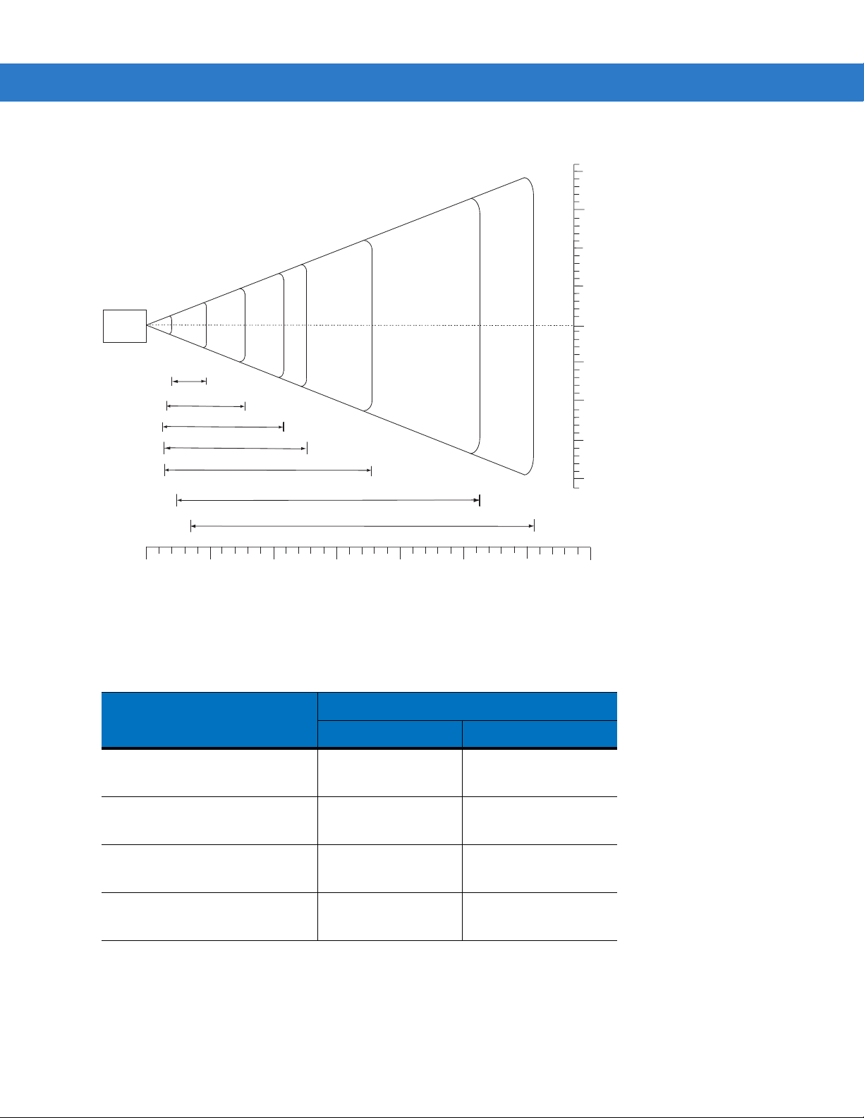
2 - 22 MC3000 User Guide
in.
cm
MC3000
5 mil
4.9
7.5 mil
10 mil
7.9
10.8
12.7
17.9
26.4
20 mil
40 mil
30.6
55 mil
W
i
d
t
h
o
f
F
i
e
l
d
Depth of Field
Note: Typical performance at 73˚ F (23˚ C)
on high quality symbols.
0
0
5
12.7
10
25.4
15
38.1
1.3
0
3
6
9
0
7.62
15.25
22.86
7.62
15.25
3
6
12 30.48
in. cm
22.869
30.4812
1.2
1.6
2.0
20
50.8
25
63.5
30
76.2
35
88.9
UPC A
1.4
2.4
3.4
Figure 2-16 MC3000 Laser Decode Ranges
Table 2-8 MC3000 Laser Decode Ranges
Bar Code Density
5.0 mil 2.0 in
7.5 mil 1.6 in
10 mil 1.2 in
UPC A 1.3 in
5.08 cm
4.06 cm
3.05 cm
3.30 cm
Ranges
Near Far
4.9 in
12.45 cm
7.9 in
20.07 cm
10.8 in
67.95cm
12.7 in
32.26 cm
Page 57

Table 2-8 MC3000 Laser Decode Ranges (Continued)
Operating the MC3000 2 - 23
20 mil 1.4 in
40 mil 2.4 in
55 mil 3.4 in
Imaging
The imager version of the mobile computer has the following features:
Imager
Bar Code Density
Near Far
3.56 cm
6.10 cm
8.64 cm
• Omnidirectional reading of a variety of bar code symbologies, including the most popular linear, postal,
PDF417 and 2-D matrix code types.
• The ability to capture and download images to a host for a variety of imaging applications.
• Advanced intuitive laser aiming for easy point-and-shoot operation.
Ranges
17.9 in
45.47 cm
26.4 in
67.06 cm
30.6 in
77.72 cm
The imager uses digital camera technology to take a digital picture of a bar code, the image is stored in memory
and software decoding algorithms are executed to extract the data from the image. A typical bar code decoding
process is as follows:
1. Aim the mobile computer at a bar code and press the scan button or trigger.
2. The red laser aiming pattern turns on to assist in aiming the mobile computer.
3. The mobile computer turns on the secondary white LEDs to illuminate the target bar code.
4. The mobile computer takes a digital picture (image) of the bar code and stores it in memory for decoding. A
beep sounds to indicate that the bar code was prop e rly de co de d .
5. Release the scan button.
This process usually occurs instantaneously. Steps 2 - 4 are repeated on poor or difficult bar codes as long as the
scan button remains active.
Operational Modes
Mobile computers with an integrated imager have three modes of operation: Decode Mode, Pick List Mode and
Image Capture Mode. All modes are activated by pulling the trigger or pressing the Scan button.
Decode Mode
This mode allows the user to decode a bar code when a single bar code in the mobile computer’s field of view. In
this mode the Imager attempts to locate and decode enable d bar codes within it s fiel d of view. The Imager remains
in this mode as long as the trigger is pulled, or until a bar code is decoded.
Page 58

2 - 24 MC3000 User Guide
Linear bar code
PDF417 symbol
Symbol
View Finder
(Aiming Pattern)
Right
Wrong
Pick List Mode
Pick List mode allows the user to selectively decode a bar code when more than one bar code is in the mobile
computer’s field of view. By moving the aiming crosshair over the wanted bar code the user can selectively read
only the required bar code. This feature is particularly valued for pick lists containing multiple bar codes and
manufacturing or transport labels containing more than one bar code type (either 1D or 2D).
Aiming the Mobile Computer
The imager version of the mobile computer projects a laser aiming pattern (shown below) similar to those used on
cameras. The aiming pattern is used to position the bar code or object within the field of view.
Figure 2-17 Laser Aiming Pattern
To scan a symbol using the imager:
1. Center the symbol in any orientation within the aiming pattern. Ensure the entire symbol is within the
rectangular area formed by the brackets in the aiming pattern.
Figure 2-18 Centering Symbol in Aiming Pattern
The imager can also read a bar code presented within the aiming pattern but not centered, such as the figure
below on the left. The figure on the right, however, can not be decoded.
Figure 2-19 Bar Code not Centered in Aiming Pattern
Note that when the mobile computer is in Pick List Mode, the bar code is not decoded until the crosshair is
touching the bar code.
Page 59

Operating the MC3000 2 - 25
Figure 2-20 Pick List Mode with Multiple Bar Codes in Aiming Pattern
2. The aiming pattern is smaller when the Imager is closer to the symbol and larger when it is farther from the
symbol. Scan symbols with smaller bars or elements (mil size) closer to the unit and those with larger bars or
elements (mil size) farther from the unit.
3. Hold the mobile computer between two and nine inches (depending on symbol density) from the symbol,
centering the aiming pattern cross hairs on the symbol.
4. Press the scan button. The Scan LED Indicators illuminate red to indicate that the laser is on. The Scan LED
Indicators illuminate green and a beep sounds to indicate a successful decode.
Imager Decode Ranges
The decode ranges provide the decode distances for barcodes of specified densities. Figure 2-21 shows the
imager decode ranges and Table 2-9 on page 2-26 lists the scan ranges for the selected bar code densities. The
minimum element width (or “symbol density”) is the width in mils of the narrowest element (bar or space) in the
symbol. The maximum usable length of a symbol at any given range is shown below.
Page 60

2 - 26 MC3000 User Guide
in.
cm
MC3000
5 mil
6.5
PDF417 6.67 mil
7.5 mil
7.7
10.7
11.1
14.2
14.4
UPC A
PDF417 15 mil
18.9
20 mil
W
i
d
t
h
o
f
F
i
e
l
d
Depth of Field
Note: Typical performance at 73˚ F (23˚ C)
on high quality symbols.
0
0
5
12.7
4.3
0
1
2
3
0
2.54
5.08
7.62
2.54
5.08
1
2
4 10.16
in. cm
7.623
10.164
3.3
5.3
4.5
10
25.4
15
38.1
PDF417 10 mil
2.5
3.8
2.8
20
50.8
5
12.7
5
12.7
15.246
15.246
Figure 2-21 MC3000 Imager Decode Ranges
Table 2-9 MC3000 Imager Decode Ranges
Bar Code Density
5.0 mil 4.5 in
7.5 mil 3.3 in
UPC A 2.5 in
20 mil 2.8 in
11.43 cm
8.38 cm
6.35 cm
7.11 cm
Ranges
Near Far
6.5 in
16.51cm
10.7 in
27.18 cm
14.2 in
36.07cm
18.9 in
48.01 cm
Page 61

Table 2-9 MC3000 Imager Decode Ranges (Continued)
LaserDot Peening
Operating the MC3000 2 - 27
Bar Code Density
Ranges
Near Far
PDF417 6.67 mil 5.3 in
13.46 cm
PDF417 10 mil 4.3 in
10.92 cm
PDF417 15 mil 3.8 in
9.65 cm
7.7 in
19.56 cm
11.1 in
28.19 cm
14.4 in
36.58 cm
Direct Part Marking
Direct Part Marking (DPM) is where an item is physically altered by methods such as dot peening, laser and
electro-chemical etching to produce two different surface conditions. These marking result in the symbol being
created by either smooth and rough (or dull and shiny) areas on the subs trate or a sym bol com pri sed “d ots” below
or above the substrate surface. DPM is typically used with matrix symbologies. As a result, there is of ten ver y little
or no contrast between the “marked” elements of a symbol and the backgro und.
Figure 2-22 Examples of Direct Part Marking
To scan a DPM symbol using the imager:
1. Center the symbol in any orientation within the aiming pattern. Ensure the entire symbol is within the
rectangular area formed by the brackets in the aiming pattern.
Symbol
View Finder
(Aiming Pattern)
Figure 2-23 Centering Symbol in Aiming Pattern
2. The aiming pattern is smaller when the Imager is closer to the symbol and larger when it is farther from the
symbol. Scan symbols with smaller elements closer to the unit and those with larger elements farther fr om the
unit.
3. Hold the mobile computer between two and nine inches (depending on symbol density) from the symbol,
centering the aiming pattern cross hairs on the symbol. Do not aim the exit wind ow directly at the surface to
avoid reflection back into the imager. Hold at a slight angle.
Page 62

2 - 28 MC3000 User Guide
4. Press the scan button. The Scan LED Indicators illuminate red to indicate that the laser is on. The Scan LED
Indicators illuminate green and a beep sounds to indicate a successful decode.
Resetting the Mobile Computer
If the mobile computer stops responding to input, reset it. There are two reset functions, warm boot and cold boot.
A warm boot restarts the mobile computer by closing all running programs. All data that is not saved is lost.
A cold boot also restarts the mobile computer, but erases all stored records and entries from RAM. In addition it
returns formats, preferences and other settings to the factory default settings.
Perform a warm boot first. If the mobile computer still does not respond, perform a cold boot.
Performing a Warm Boot
To perform a warm boot on 28, 38 and 48-key keypad configurations:
1. Press and simultaneously hold 7, 9 and Power. Do not hold down any other keys or buttons.
2. As the mobile computer initializes MC3000 demo window appears.
CAUTION Files that remain open during a warm boot may not be retained.
To perform a warm boot on 20-key keypad configurations:
1. Press and simultaneously hold the 7 and 9 keys and the press the MENU and Fn keys. Do not hold down any
other keys or buttons.
2. As the mobile computer initializes MC3000 demo window appears.
CAUTION Files that remain open during a warm boot may not be retained.
Performing a Cold Boot
A cold boot restarts the mobile computer and e rases all u ser sto red re co rd s and en tr ies fr om RAM. Ne ve r pe rfor m
a cold boot unless a warm boot does not solve the problem.
CAUTION Cold boot resets the mobile computer, to the default settings. All added applications and all stored data are
removed. Do not cold boot without support desk approval.
To perform a cold boot 28, 38 and 48-key keypad configurations:
1. Simultaneously press and then release the 1, 9 and Power keys. Do not hold down any other keys or buttons.
As the mobile computer initializes, the Symbol splash window, Figure 1-7 on page 1-9, appears for about a
minute.
2. Calibrate the touch screen. See Calibration Screen on page 1-10 to calibrate the mobile computer screen.
To perform a cold boot on 20-key keypad configurations:
1. Simultaneously press and then release the 1 and 9, MENU and Fn keys. Do not hold down any other keys or
buttons. As the mobile computer initializes, the Symbol splash window, Figure 1-7 on page 1-9, appears for
about a minute.
Page 63

2. Calibrate the touch screen. See Calibration Screen on page 1-10 to calibrate the mobile computer screen.
Waking the Mobile Computer
The wakeup conditions define what actions wake up the mobile co mputer after it has gone into suspe nd mode. The
mobile computer can go into suspend mode by either pressing the Power button or automatically by Control Panel
time-out settings. These settings are configurable and the factory default settings are shown in Table 2-10.
Table 2-10 Wakeup Default Settings
Condition for Wakeup Power Button Automatic Time-out
AC power is applied. No Yes
Mobile computer is inserted into a cradle. No Yes
Mobile computer is removed from a cradle. No Ye s
Mobile computer is connected to a serial device. No Yes
Mobile computer is connected to a USB device. No Yes
Operating the MC3000 2 - 29
Mobile computer is disconnected from a USB device. No Yes
A key is pressed. No Yes
The scan triggered is pressed. No Yes
The screen is touched. No No
Wireless LAN activity is detected. No No
File System Directory Structure
The mobile computer directory structure displays all of the file folders. The pre-installed folders are in flash file
system memory and optional removable storage devices (SD storage cards).
Figure 2-24 Mobile Computer Directory Structure
• Application and Platform folders are located in flash file system memory.
Page 64

2 - 30 MC3000 User Guide
•The Windows, Program Files, profiles, and My Documents folders are composites, RAM based folders
generated from ROM (many of these files are marked read only).
•The Network folder is a link to file systems mapped using the network redirector. The files do not physically
reside on the mobile computer.
•The Temp and Recycled folders typically contain RAM based files.
NOTE All files copied to the RAM based folders are lost after a cold boot.
Connecting to the Internet on a Wireless LAN Network
The mobile computer can connect to the Internet across a wireless LAN network. The Wireless Applications utility
starts automatically when the mobile computer is turned on and the wirele ss application icon appear s in the taskb ar
to indicate the connection and the signal strength status. Before attempting a wirele ss internet con nection, confirm
that the wireless application radio is connecte d to a wire less LAN network. If the WLAN ra dio is not connected or if
the signal strength is not “Good” or better, contact the network administrator.
Table 2-11 Wireless Applications Icons, Signal Strength Descriptions
Icon Status Action
Excellent signal strength Wireless LAN network is ready to use.
Very good signal strength Wireless LAN network is ready to use.
Good signal strength Wireless LAN network is ready to use.
Fair signal strength Wireless LAN network is ready to use. Notify the network administrator
that the signal strength is only “Fair”.
Poor signal strength Wireless LAN network is ready to use. Perfor mance may not be optimum.
Notify the network administrator that the signal strength is “Poor”.
Out-of-network range (not
No wireless LAN network connection. Notify the network administrator.
associated)
No wireless LAN network card
No wireless LAN network card detected. Notify the network administrator.
detected.
To connect using Internet Explorer (IE) tap
NOTE IE is provided only on mobile computers provided with Microsoft
not provided on mobile computers with Microsoft® Windows CE .NET 5.0 Core.
Start > Programs > Internet Explorer to start Internet Explorer.
®
Windows CE .NET 5.0 Professional. IE is
Page 65

Figure 2-25 Typical Internet Explorer (IE) Connection
Operating the MC3000 2 - 31
Page 66

2 - 32 MC3000 User Guide
Page 67

Chapter 3 Using Bluetooth
Introduction
Bluetooth-equipped devices can communicate without wires, using frequency-hopping spread spectrum (FHSS)
RF to transmit and receive data in the 2.4 GHz Industry Scientific and Medical (ISM) band (802.15.1). Bluetooth
wireless technology is specifically designed for short-range (30 feet/10 meters) communications and low power
consumption.
Mobile computers with Bluetooth capabilities can exchange information (e.g., files, appointments and tasks) with
other Bluetooth enabled devices such as phones, printers, access points and other mobile computers. In addition,
a dial-up modem connection can be create d be tw ee n th e Bluetooth mobile computer and a Bluetooth enabled
phone. The Bluetooth phone can then be used as a modem.
Symbol mobile computers with Bluetooth technology use the StoneStreet One Bluetooth stack. To program
Bluetooth within the mobile computer refer to the StoneStreet One SDK.
Adaptive Frequency Hopping
Adaptive Frequency Hopping (AFH) is a method of avoiding fixed frequency interferers. AFH can be used with
Bluetooth voice. All devices in the piconet (Bluetooth network) must be AFH-capable in order for AFH to work.
There is no AFH when connecting and discovering devices. Avoid making Bluetooth connections and discoveries
during critical 802.11b communications. AFH for Bluetooth can be broken-down into four main sections:
• Channel Classification - A method of detecting an interference on a cha nnel-by-channel b asis, or pre-defin ed
channel mask.
• Link Management - Coordinates and distributes the AFH information to the rest of the Bluetooth network.
• Hop Sequence Modification - Avoids the interference by selectively reducing the number of hopping
channels.
• Channel Maintenance - A method for periodically re-evaluating the channels.
When AFH is enabled, the Bluetooth radio “hops-around” (in stead of through) the 802.11b high-rate channels. AFH
coexistence allows Symbol mobile computers to operate in any infrastructure. AFH is always enabled in the
MC3000.
The Bluetooth radio in this mobile computer operates as a Class 2 de vice power class. The maximum output power
is 2.5mW and the expected range is up to 32.8 feet (10 meters). A definitive definition of ranges based on power
Page 68

3 - 2 MC3000 User Guide
class is difficult to obtain due to power and device differences, and whether one measures open space or closed
office space.
NOTE It is not recommended to perform Bluetooth wireless technology inquiry when high rate 802.11b operation is
required.
Security
The current Bluetooth specification defines security at the link level. Application-level security is not specified. This
allows application developers to define security mechanisms tailored to their specific need. Link-level security is
really between devices not users, while application-level security can be implemented on a per-user basis. The
Bluetooth specification defines security algorithms and procedures ne eded to authenticate device s, and if nee ded,
encrypt the data flowing on the link between the devices. Device authentication is a mandatory feature of Bluetooth
while link encryption is optional.
Pairing of Bluetooth devices is accomplished by creating an initialization key that is used to authenticate the
devices and create a link key for them. Entering a common PIN number in the devices being paired generates the
initialization key. The PIN number is never sent over the air. By default, the Bluetooth stack responds with no key
when a key is requested (it is up to user to respond to the key request event). Authentication of Bluetooth devices
is based-upon a challenge-response transaction. Bluetooth allows for a PIN number or passkey that is used to
create other 128-bit keys used for security and encryption. The encryption key is derived from the link key used to
authenticate the pairing devices. Also worthy of note is the limited range and fast frequency hopping of the
Bluetooth radios that makes long-distance eavesdropping difficult.
It is recommended:
• Perform pairing in a secure environment
• Keep PIN codes private and don't store the PIN codes in the mobile computer
• Implement application-level security.
Turning the Bluetooth Radio Mode On and Off
Turn off th e Bluetooth radio to save po wer or if entering an area with radio r estrictions (e.g., a n airplane). When th e
radio is off, the mobile computer can not b e seen or connected to b y other Bluetooth devices. T urn on the Bluetooth
radio to exchange information with other Bluetooth devices (within range). Comm unicate only with Bluetooth radios
in close proximity.
NOTE To achieve the best battery life in mobile computers with multiple radios, turn off the radios that are not being
used.
Disabling Bluetooth
To disable Bluetooth, tap Bluetooth icon > Disable Bluetooth. The Bluetooth icon changes to indicate that Bluetooth
is disabled. An exclamation point appears with the icon.
Page 69
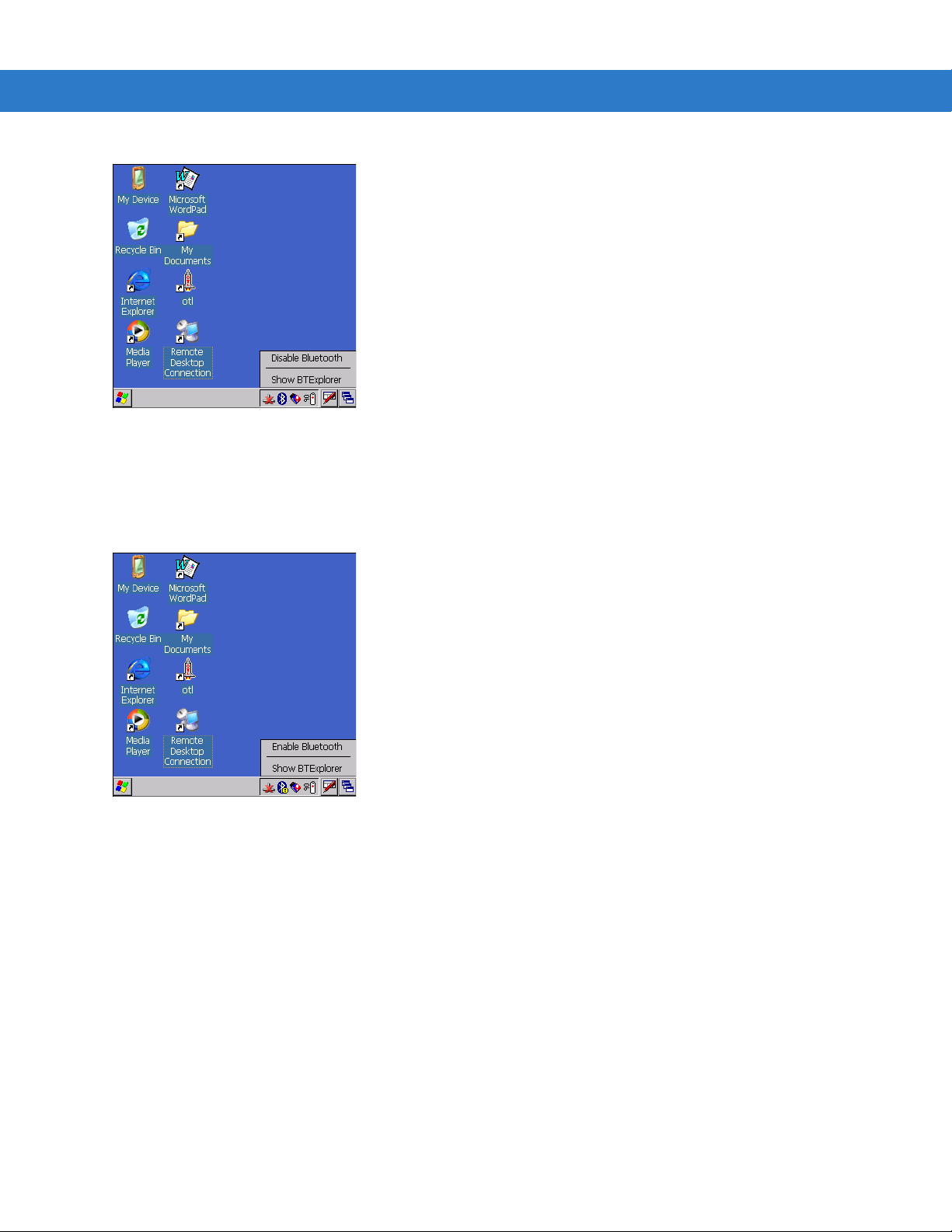
Using Bluetooth 3 - 3
Figure 3-1 Disable Bluetooth
Enabling Bluetooth
To enable Bluetooth, tap Bluetooth icon > Enable Bluetooth. The Bluetooth icon changes to indicate that Bluetooth
is enabled.
Figure 3-2 Enable Bluetooth
Bluetooth Power States
Cold Boot
When a cold boot is performed on the mobile computer, Bluetooth turns off. It is normal to see the Bluetooth icon
appear and disappear, as well as a wait cursor, when initialization proceeds in all modes.
Warm Boot
When a warm boot is performed on the mobile computer, Bluetooth returns to the disabled state (off).
Page 70
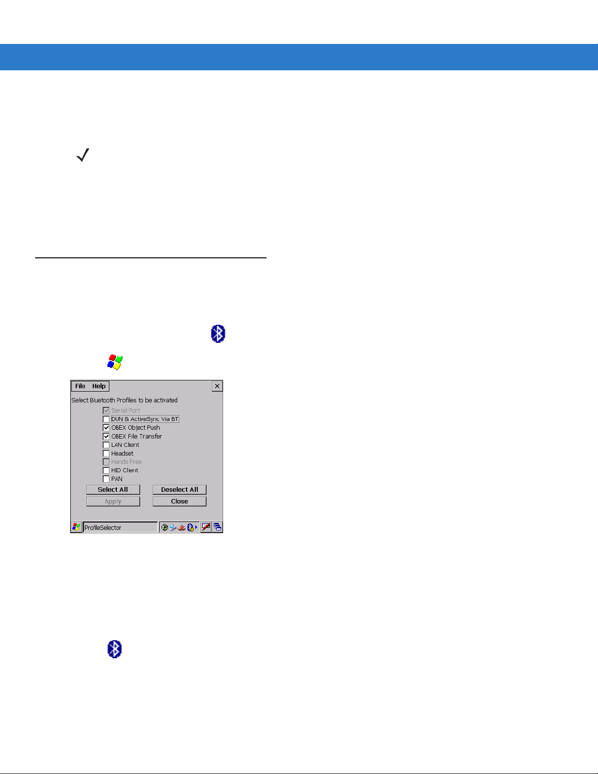
3 - 4 MC3000 User Guide
Suspend
When the mobile computer suspends, Bluetooth turns off.
NOTE When the mobile computer is placed in suspend mode, the Bluetooth radio mode powers off and the piconet
(Bluetooth connection) is dropped. When the mobile computer resumes, it could take up to 10 seconds for the
Bluetooth radio driver to re-initialize the radio.
Resume
When the mobile computer resumes, Bluetooth turns on if it was on prior to suspend. Note that any Bluetooth
connection that was dropped during a suspend needs to be reconnected after a resume.
Bluetooth Profiles
The mobile computer is loaded with a number of Bluetooth services profiles. These profiles can be loaded or
removed from memory. If a profile is not used, it can be removed to save memory. To load or remove profiles:
BTExplorer is running, tap > Disable Bluetooth.
1. If
2. Tap >
Figure 3-3 Bluetooth Profile Selector Window
3. Tap a check box next to the profile to load (activate).
The Serial Port profile is always active and cannot be removed.
4. Tap
5. Tap
Programs > BTProfileSelctor. The ProfileSelector window appears.
Select All to select all profiles or tap Deselect All to deselect all profiles.
Apply to activate the profiles and then Close to exit the application.
6. Tap >
See Services Tab on page 3-22 for more information on selecting services.
Enable Bluetooth to enable BTExplorer application.
Page 71
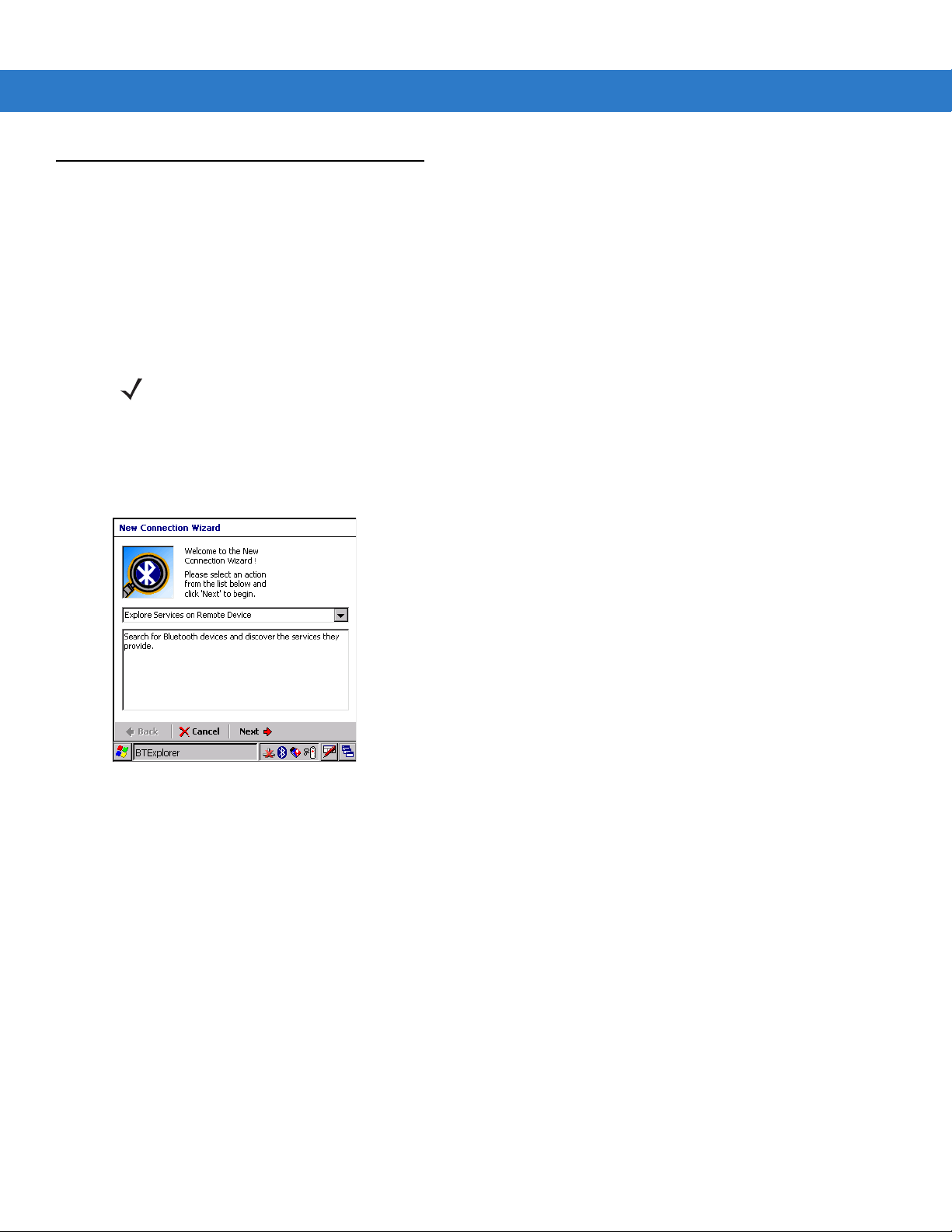
Modes
The BTExplorer application has two mode for managing Bluetoo th conne ction s: Wiza rd Mod e and Expl ore r Mode.
The Wizard Mode is for novice Bluetooth users and the Explorer Mode is for experienced Bluetooth users.
Wizard Mode
Wizard Mode provides a simple step by step process for discovering and connecting to Bluetooth devices. The
wizard takes you through the entire process.
The following steps provide an example for using the Wizard to services for remote devices.
Using Bluetooth 3 - 5
NOTE When switching between Wizard Mode and Explorer Mode, all active connections are closed.
1. Tap the
2. Tap
Figure 3-4 New Connection Wizard Window
3. Select an action from the drop-down list. In this example,
4. Tap
Remote Device
Bluetooth icon and select Show BTExplorer. The BTExplorer window appears.
File > New Connection. The New Connection Wizard window appears.
Next. The BTExplorer searches for Bluetooth devices in the area and displays the devices in the Select
window.
Explore Services on Remote Device is selected.
Page 72
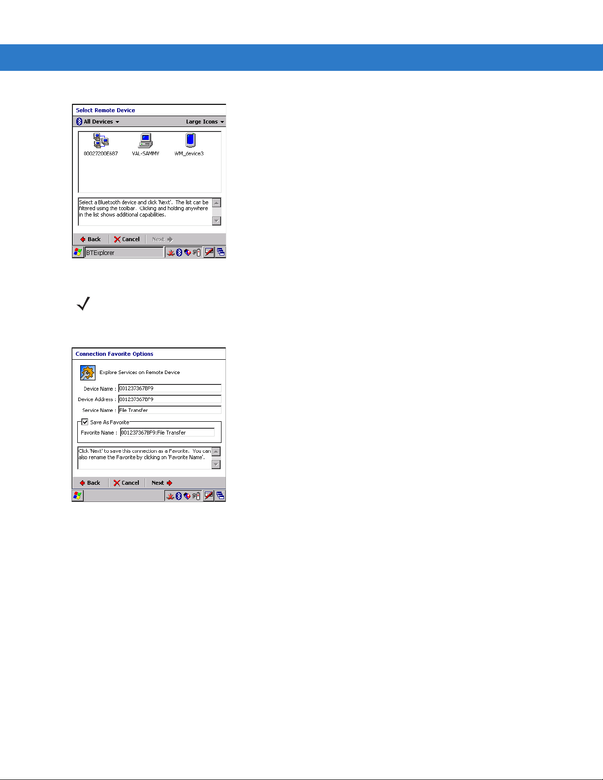
3 - 6 MC3000 User Guide
Figure 3-5 Select Remote Device Window
NOTE Devices discovered previously are listed to save time. To start a new device discovery, tap and hold and select
Discover Devices from the menu.
5. Select a device from the list and then tap
Next. The Connection Favorite Options window appears.
Figure 3-6 Connection Favorite Options Window
6. Select
7. In the
8. Tap
Save As Favorite check box to save this service in the Favorite view.
Favorite Name text box, enter a name for this service that will appear in the Favorite list.
Next. The Connection Summary window appears.
Page 73
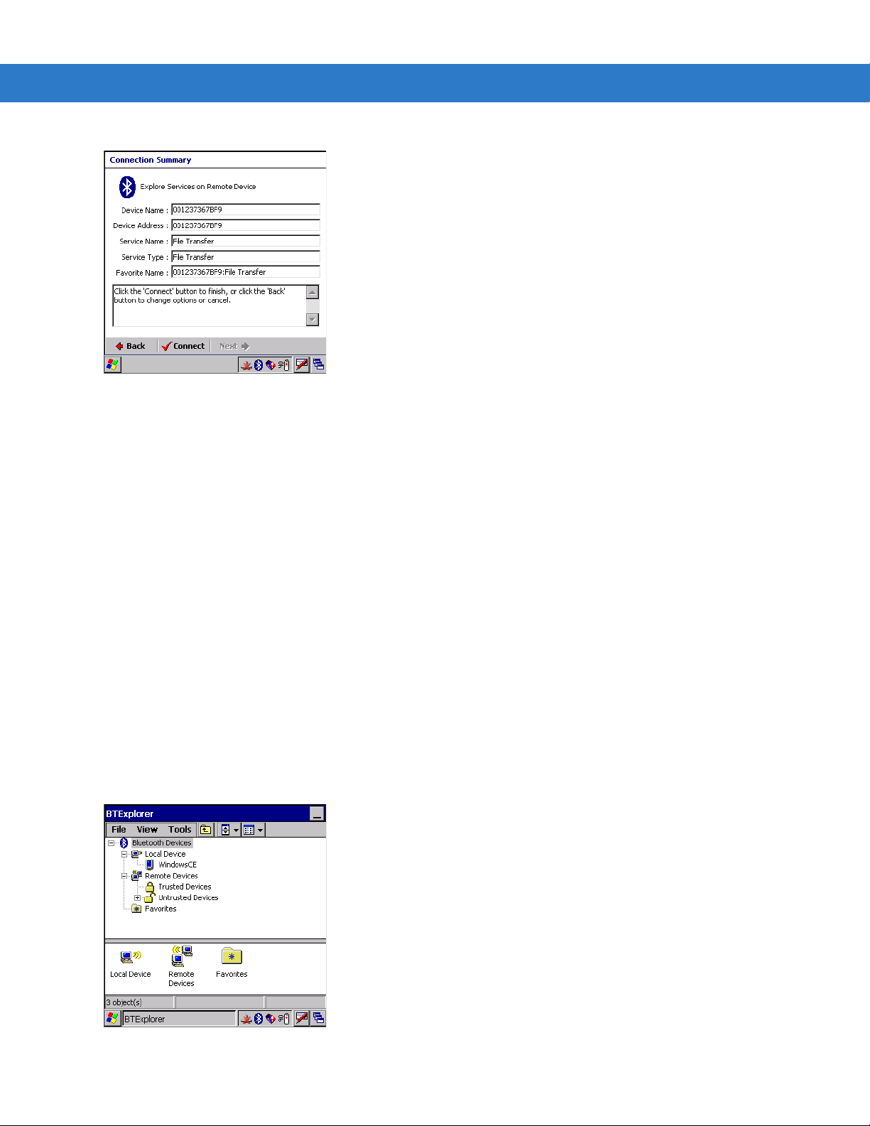
Figure 3-7 Connection Summary Window
Using Bluetooth 3 - 7
9. Tap
The following actions are available in the drop-down list (actions may vary depending upon configurations):
Connect to connect to the service.
• Explore Services on Remote Device
• Pair with a Remote Device
• ActiveSync via Bluetooth
• Browse Files on Remote Device
• Connect to Internet Using Access Point
• Connect to Internet Using Phone/Modem
• Connect to a Personal Area Network
• Send or Exchange Objects
• Associate Serial Port.
Explorer Mode
The BTExplorer window is streamlined and easy to navigate and provides greater control to users familiar with
Bluetooth functionality. The menu bar provides quick access to the options and tools used to connect to devices.
Figure 3-8 Explorer Mode Window
Page 74

3 - 8 MC3000 User Guide
You can also use the “tap and hold” tec hnique to view available options. Scroll bars and view options are like those
you’re familiar with on your Windows desktop. The tree structure lists the following sub-items:
• Local Device - This MC3000 mobile computer
• Remote Device - Other Bluetooth devices
• Trusted Devices - Bonded (paired) Bluetooth devices
• Untrusted Devices - Discovered devices that are not bonded
• Favorites - Selected services that are set as being
NOTE When switching between Wizard Mode and Explorer Mode, all active connections are closed.
Discovering Bluetooth Device(s)
Follow the steps below to discover Bluetooth devices. The mobile computer can receive information from
discovered devices, without bonding. However, once bonded, an exchange of information between the mobile
computer and a bonded device occurs automatically when the Bluetooth radio is turned on.
To find Bluetooth devices in the area:
1. Ensure that the Bluetooth device being looked for is in discoverable mode.
2. Ensure that the two devices are within 30 feet (10 meters) of one another.
3. Tap the
Bluetooth icon and select Show BTExplorer. The BTExplorer window appears.
Favorite for quick access.
Figure 3-9 BTExplorer Window
4. Tap and hold
searches for Bluetooth devices in the area.
Remote Devices and select Discover Devices from the pop-up menu. The mobile computer
Page 75

Figure 3-10 Discover Devices
Using Bluetooth 3 - 9
5. The discovered devices display in the
Figure 3-11 Discovered Devices Listed in Untrusted Folder
Untrusted Devices folder.
Bonding with Discovered Device(s)
A bond is a relationship created between the mobile computer and another Bluetooth device in order to exchange
information in a secure manner . Creating a bond involves entering the same PIN on th e two devices to bond. Once
a bond is created, and the Bluetooth radios are turned on, the devices recognize the bond and are able to
exchange information without re-entering a PIN.
To bond with a discovered Bluetooth device:
1. Discover remote devices. See Discovering Bluetooth Device(s) on page 3-8.
2. In the
Untrusted Devices folder, tap and hold on a device to pair with.
Page 76

3 - 10 MC3000 User Guide
Figure 3-12 Pair a Remote Device
3. Select
4. On the mobile computer, the
Pair from the pop-up menu.
PIN Code Request window appears.
Figure 3-13 PIN Code Request Window
5. In the
PIN Code: text box, enter the PIN number (between 1 and 16 characters) and then tap OK.
6. On the remote device, enter the same PIN number.
7. The devices are successfully paired. The device name moves to the
Trusted Devices folder.
Figure 3-14 Bonded (Paired) Discovered Device
Page 77

Renaming a Bonded Device
If it is necessary to rename a bonded device, it can be done fro m the BTExplorer window.
Using Bluetooth 3 - 11
1. Launch
2. Tap and hold the device to rename and select
Figure 3-15 Rename Device Selection Dialog Box
3. The
BTExplorer.
Change Device Name window appears.
Rename in the pop-up menu.
Figure 3-16 Change Device Name Window
4. Enter a new name for the bonded device in the text box. Tap OK.
Deleting a Bonded Device
If it is no longer necessary to connect with a device, delete it from the Bluetooth Bonded Devices window.
1. Launch
2. Tap and hold the device to delete and.select
BTExplorer.
Delete in the pop-up menu.
Page 78

3 - 12 MC3000 User Guide
Figure 3-17 Delete a Bonded Device
3. A confirmation dialog appears. Tap Yes.
Accepting a Bond
When a remote device wants to bond with a mobile computer you give permission by entering a PIN when
requested.
1. Ensure that the mobile computer is set to discoverable and connectable. See Bluetooth Settings on page 3-21.
2. When prompted to bond with the remote device the
PIN Code Request window appears.
Figure 3-18 PIN Code Request Window
NOTE Connections to untrusted devices are a security risk.
3. In the
PIN Code: text box, enter the same PIN that was entered on the device requesting the bond. The PIN
must be between 1 and 16 characters.
4. In the
Device Name: text box, edit the name of the device requesting the bond, if desired.
5. Tap OK.
6. The bond is created and the mobile computer can now exchange information with the other device.
Page 79

Using Bluetooth 3 - 13
Discovering Services
Before services can be used, you must first discover remote devices and then bond to those devices.
To determine what services are available on a bonded remote device:
1. Tap the
2. In
Figure 3-19 Discovering Services
3. The mobile computer communicates with the remote device and then lists the services under th e device name.
Bluetooth icon and select Show BTExplorer.
BTExplorer window, tap and hold on the remote device and select Explore from the pop-up menu.
Figure 3-20 List of Discovered Services
Some examples of available services are:
• File Transfer Services
• Dial-Up Networking Services
• Headset or Hands-Free Services
• OBEX Object Push Services
• Serial Port Services
These services are discussed in the following paragraphs.
Page 80
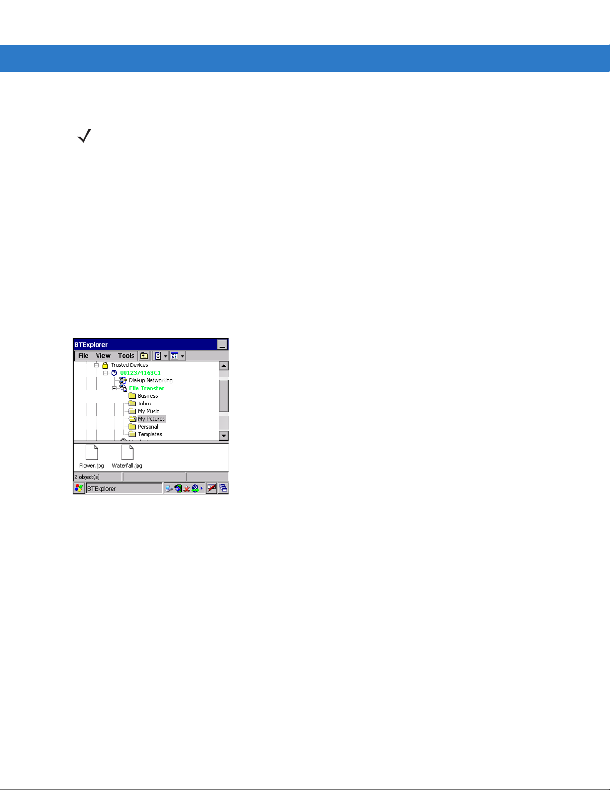
3 - 14 MC3000 User Guide
File Transfer Services
NOTE Shared folders are a security risk.
To transfer files between the mobile computer and another Bluetooth enabled device:
1. Ensure the mobile computer is discoverable and connectable. See Bluetooth Settings on page 3-21.
2. Discover and bond (pair) with the remote access point.See Bonding with Discovered Device(s) on page 3-9.
BTExplorer, select the Remote Devices folder.
3. In
4. Select the
Trusted Devices folder.
5. Tap the remote device folder.
6. Tap and hold on the remote device and select
7. Tap and hold on
File Transfer and select Connect. The remote device’s accessible folders appear.
Explore from the pop-up menu.
8. Select a folder. The contents of the folder appear in the sub-window.
Figure 3-21 Remote Device Folders
9. Tap and hold on the file. A pop-up menu appears.
10. Select the action to perform:
a. New - create a new file or folder. on the remote device
b. Delete - delete the selected file on the remote device.
c. Get File - copy the file from the remote device to the mobile computer.
d. Put File - copies a file from the mobile computer to the remote device.
Create New File or Folder
To create a new folder or file on the remote device:
1. Tap and hold on the file and select
window appears.
2. Enter the name for the new folder or file. Tap
3. A new folder or file is created on the remote device.
New > Folder or New > File. The Create New Folder or Create New File
OK.
Page 81

Delete File
To delete a file from the remote device:
Using Bluetooth 3 - 15
1. Tap and hold on the file and select
2. In the
Delete Remote Device File dialog box tap OK.
Delete.
Get File
To copy a file from a remote device:
1. Tap and hold on the file and select
2. Navigate to the directory to save the file.
3. Tap
Save. The file is transferred from the remote device to the mobile computer.
Get. The Save Remote File window appears.
Put File
To copy a file to a remote device:
1. Tap and hold on the file and select
2. Navigate to the directory to save the file and select a file.
3. Tap
Open. The file is transferred from the mobile computer to the remote device.
Put. The Send Local File window appears.
Connect to Internet Using Access Point
This section explains how to access a Bluetooth-enabled LAN access point (AP) for a network connection. With
this method of communication the Internet Explorer can be used to connect to a server.
1. Ensure the mobile computer is discoverable and connectable. See Bluetooth Settings on page 3-21.
2. Discover and bond (pair) with the remote access point.See Bonding with Discovered Device(s) on page 3-9.
3. In
BTExplorer, select the Remote Devices folder.
4. Select the
5. Tap the remote device folder.
6. Tap and hold on the remote device and select
7. Tap and hold
8. The mobile computer connects with the Access Point.
9. Tap
10. In the address field, enter an internet address and tap the
Trusted Devices folder.
Explore from the pop-up menu.
LAN Access using PPP service and select Connect from the pop-up menu.
Start > Internet Explorer. The Internet Explorer window appears.
Enter button. The web page loads.
Dial-Up Networking Services
To use a phone that has Bluetooth capabilities as a modem for the mobile computer, create a Bluetooth modem
connection on the mobile computer and send information to the phone using Bluetooth. The phone relays the
information over the phone line and sends back to the mobile comp uter any information that was requested over
the connection. Once a modem connection is created to the Bluetooth phone, it can be reused.
Page 82

3 - 16 MC3000 User Guide
Prior to creating a connection, ensure the following:
• Bluetooth phone is turned on.
• Bluetooth phone is discoverable. (Some phones may also need to be pairable in order to accept a bonding
request. For more information, refer to the phone documentation.)
• Mobile computer’s and phone's Bluetooth radios are turned on.
• Mobile computer and phone are within range of each other (30 feet/10 meters).
Complete the following steps to create a new Bluetooth connection. Before setting up dial-up networking, obtain
dial-up information and other necessary settings for the office network or ISP.
1. Ensure the mobile computer is discoverable and connectable. See Bluetooth Settings on page 3-21.
2. Discover and bond (pair) with the remote device.See Bonding with Discovered Device(s) on page 3-9.
3. In
BTExplorer, select the Remote Devices folder.
4. Select the
Trusted Devices folder.
5. Tap the remote device folder.
6. Tap and hold on
Entry
window appears.
Dial-up Networking and select Connect from the pop-up menu. The Select Dial-up Networking
Figure 3-22 Select Dial-up Networking Entry Window
NOTE If a dial-up entry is not listed, see Add a Dial-up Entry on page 3-17.
7. Select a dial-up entry.
8. Tap
OK. The mobile computer begins to communicate with the phone. If required, the phone requests
permission to communicate with the mobile computer.
9. Confirm the connection on the phone. The
Network Log On window appears.
Page 83

Figure 3-23 Network Log On Window
Using Bluetooth 3 - 17
10. In the
11. In the
12. In the
13. Tap
User name: text box, enter the user name for this connection.
Password: text box, enter the password for this connection.
Domain: text box, enter the domain for this connection, if required.
OK.
14. The phone begins dialing.
15. The phone connects to the network.
16. To end a session, tap the
Connection icon and then tap Disconnect in the dialog box.
Add a Dial-up Entry
To add a dial-up entry:
1. In the
Select Dial-up Networking Entry window, tap and hold and then select Add Entry from the pop-up menu.
Figure 3-24 Add Dial-Up Entry
2. The
Add Phone Book Entry window appears.
Page 84
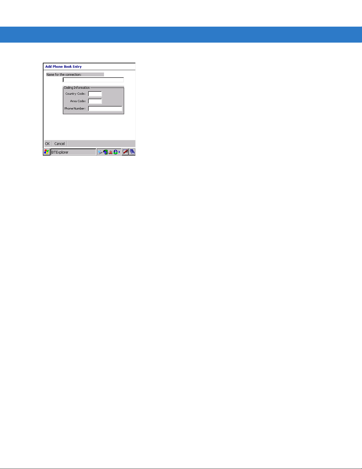
3 - 18 MC3000 User Guide
3. In the Name for the connection text box, enter a name for this conne ctio n.
4. In the
5. In the
6. In the
7. Tap
Country Code text box, enter the country code for the country that you are calling.
Area Code text box, enter the area code.
Phone Number text box, enter the phone number.
OK.
OBEX Object Push Services
Object Exchange (OBEX) is a set of protocols allowing objects such as pictures to be shared using Bluetooth.
To exchange information with another Bluetooth enabled device:
1. Ensure the mobile computer is discoverable and connectable. See Bluetooth Settings on page 3-21.
2. Discover and bond (pair) with the remote device.See Bonding with Discovered Device(s) on page 3-9.
BTExplorer, select the Remote Devices folder.
3. In
4. Select the
5. Tap the remote device folder.
6. Tap and hold on
7. In the
Fetch Contact Information or Send a Picture.
Trusted Devices folder.
OBEX Object Push and select Connect. The OBEX Object Push window appears.
Action drop-down list, select one of the options: Send Contact Information, Swap Contact Information,
Send a Picture
To send a picture to another device:
1. Ensure the mobile computer is discoverable and connectable. See Bluetooth Settings on page 3-21.
2. Discover and bond (pair) with the remote device.See Bonding with Discovered Device(s) on page 3-9.
3. In
BTExplorer, select the Remote Devices folder.
4. Select the
5. Tap the remote device folder.
6. Tap and hold on
Trusted Devices folder.
OBEX Object Push and select Connect. The OBEX Object Push window appears.
Page 85
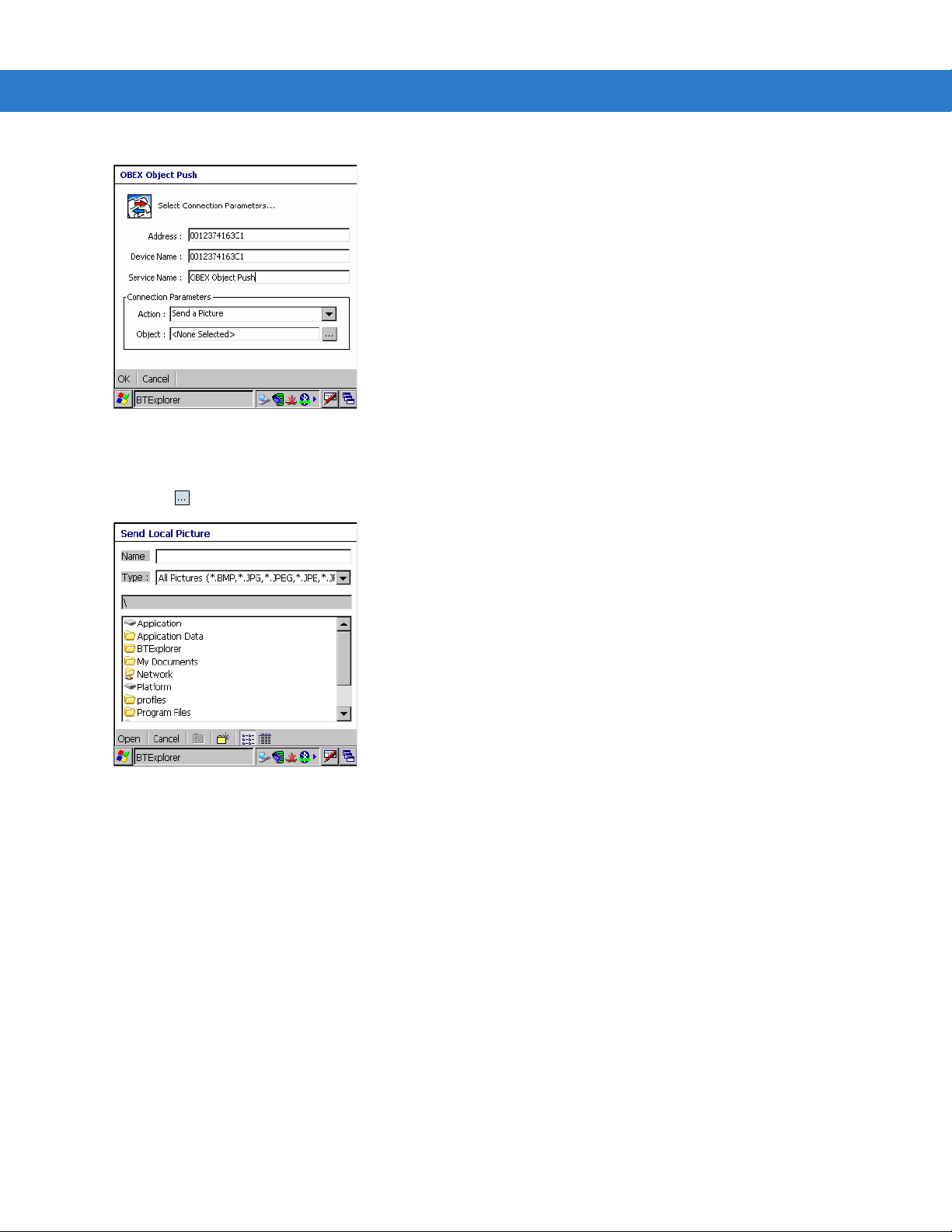
Figure 3-25 OBEX Object Push Window
Using Bluetooth 3 - 19
7. In the
8. Tap . The
Action drop-down list, select Send A Picture.
Send Local Picture window appears.
Figure 3-26 Send Local Picture Window
9. Navigate to the picture that you wa nt to send to the ot he r de vice .
10. Tap
11. Tap
Open.
OK. The picture is sent to the other device and a confirmation dialog box appears on the other device to
accept the picture. A
Send Picture dialog appears.
12. Tap
Ok.
Headset Services
To connect to a Bluetooth headset:
1. Ensure the mobile computer is discoverable and connectable. See Bluetooth Settings on page 3-21.
2. Discover and bond (pair) with the headset.See Bonding with Discovered Device(s) on page 3-9.
3. In
BTExplorer, select the Remote Devices folder.
4. Select the
Trusted Devices folder.
Page 86
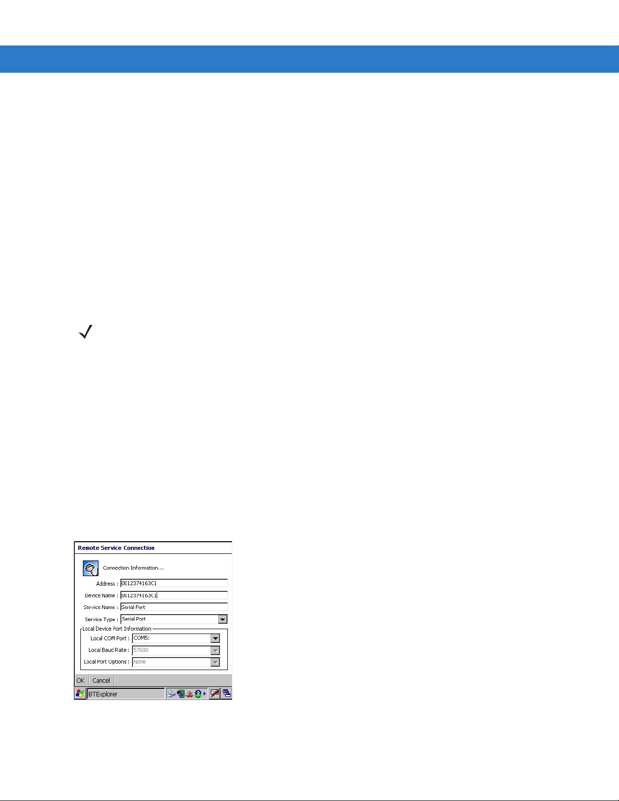
3 - 20 MC3000 User Guide
5. Tap the remote device folder.
6. Tap and hold on the remote device and select
7. Tap and hold on the headset service name and select
Explore. A headset service item appears.
Connect.
8. The mobile computer connects to the headset. Refer to your headset user manual for instruction on
communicating with a Bluetooth device.
To adjust the microphone gain:
1. Tap and hold on the headset service item and select
Microphone Properties window appears.
Adjust Microphone from the pop-up menu. The
2. Select the slider and adjust the gain.
3. Tap
OK.
Serial Port Services
NOTE By default, COM ports COM4, COM5 and COM9 are Bluetooth virtual ports. If an application opens one of
these ports, the Bluetooth driver activates and guides you through a Bluetooth connection.
Use the wireless Bluetooth serial port connection just as you would a physical serial cable connection. You must
configure the application that will use the connection to the correct serial port.
To establish a serial port connection:
1. Ensure the mobile computer is discoverable and connectable. See Bluetooth Settings on page 3-21.
2. Discover and bond (pair) with the remote device.See Bonding with Discovered Device(s) on page 3-9.
3. In
BTExplorer, select the Remote Devices folder.
4. Select the
Trusted Devices folder.
5. Tap the remote device folder.
6. Tap and hold
Serial Port and select Connect in the pop-up menu. The Remote Service Connection window
appears.
Figure 3-27 Remote Service Connection Window
7. In the
8. Tap
OK.
Local COM Port drop-down list select a COM port.
Page 87
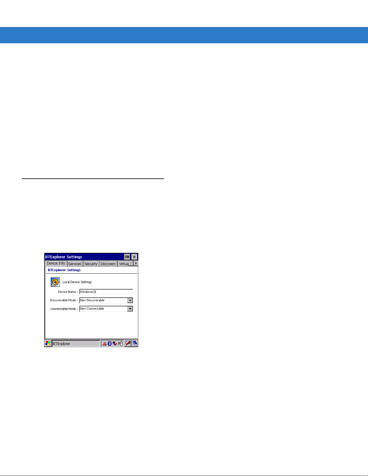
Using Bluetooth 3 - 21
Personal Area Network Services
Connect two or more Bluetooth devices to share files, collaborate or play multi player games.
To establish a Personal Area Network connection:
1. Ensure the mobile computer is discoverable and connectable. See Bluetooth Settings on page 3-21.
2. Discover and bond (pair) with the remote device.See Bonding with Discovered Device(s) on page 3-9.
3. In
BTExplorer, select the Remote Devices folder.
4. Select the
5. Tap the remote device folder.
6. Tap and hold
Trusted Devices folder.
Bluetooth Settings
Use the BTExplorer Settings window to configure the operation of the BTExplorer application . Tap Tools > Settings.
The
BTExplorer Settings window appears.
Device Info Tab
Use the Device Info tab to configure the mobile computer’s Bluetooth connection modes.
Personal Area Network and select Connect in the pop-up menu.
Figure 3-28 BTExplorer Settings - Device Info Tab
Device Name Displays the name of the mobile computer.
Discoverable Mode Allows you to set the mobile computer to be discoverable by other Bluetooth devices or not be
discoverable.
Note:
For security reasons, the default is set to
Connectable Mode Allows you to set the mobile computer to be connectable by other Bluetooth devices or not be
connectable.
Note:
For security reasons, the default is set to
Non Discoverable
Non Connectable
.
.
Page 88
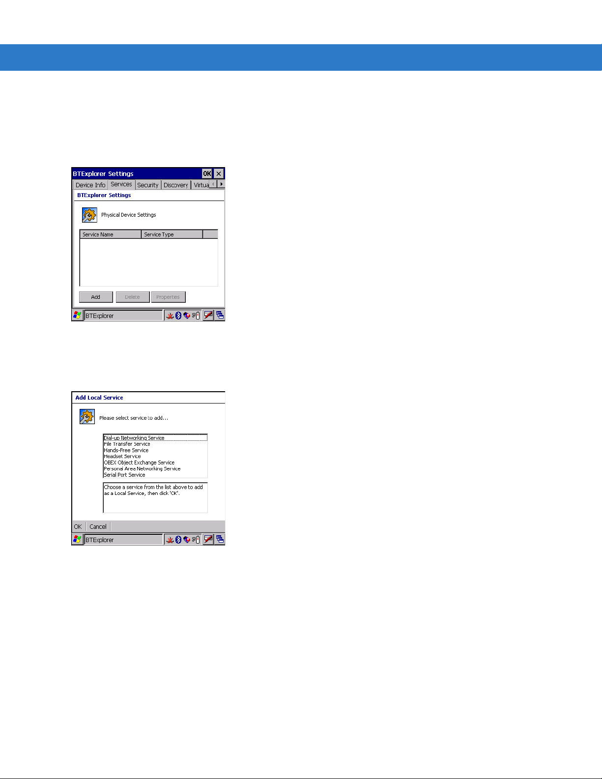
3 - 22 MC3000 User Guide
Services Tab
For security reason, by default services are not enabled.
Use the
Figure 3-29 BTExplorer Settings - Services Tab
To add a service:
1. Tap
Services tab to add or delete Bluetooth services.
Add. The Add Local Service window displays.
Figure 3-30 Add Local Service Window
2. In the list, select a service to add.
3. Tap
4. Select the appropriate information and then tap
OK. The Edit Local Service window displays for the selected service.
OK. See the following paragraphs for detailed informa tion on
the available services.
Dial-Up Networking Service
Dial-up Networking allows a dial-up modem to be accessed by other Bluetooth devices.
Page 89
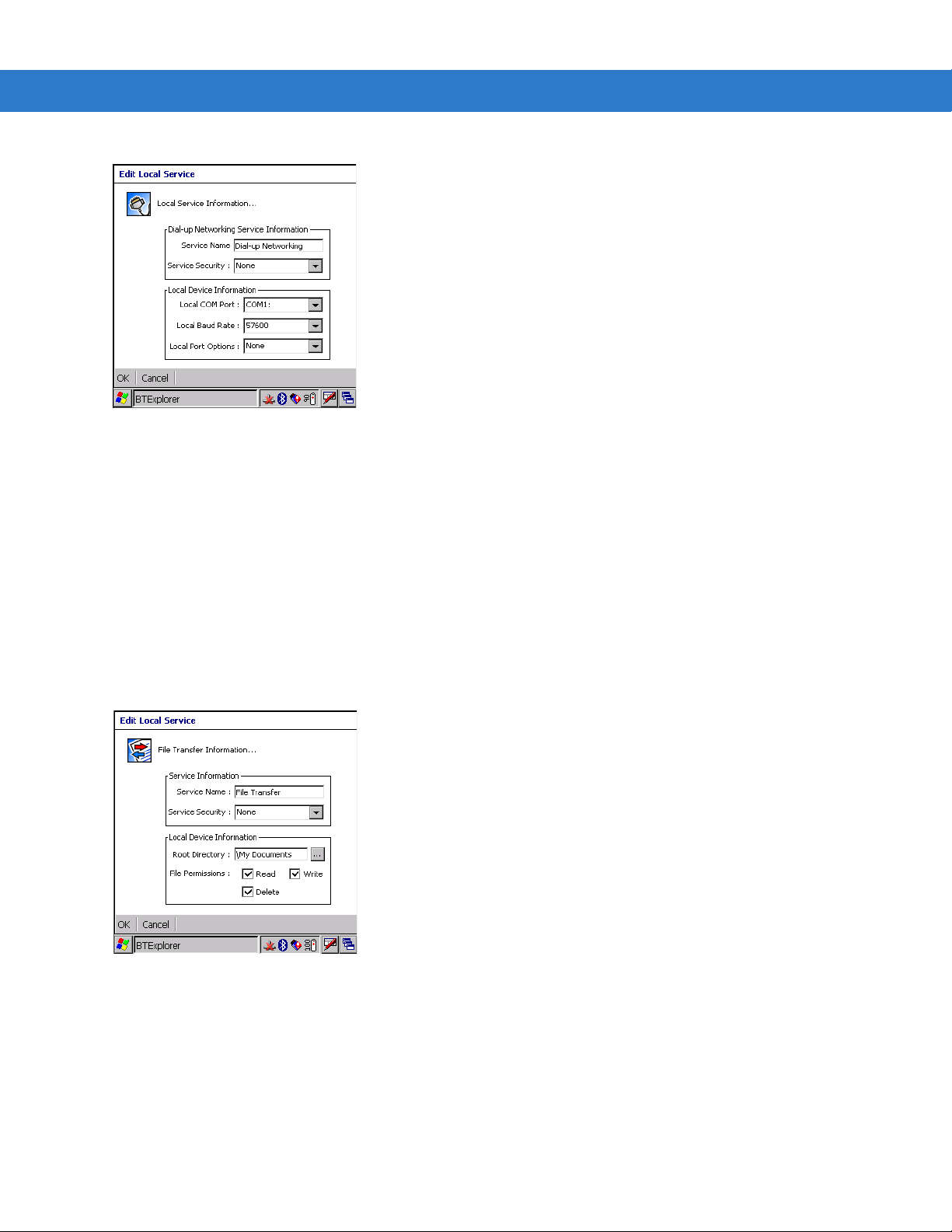
Using Bluetooth 3 - 23
Figure 3-31 Add Local Service Window
Service Name Displays the name of the service.
Service Security Select the type of security from the drop-down list;
Authenticate/Encrypt
.
Local COM Port Select the COM port. Select COM1 to use a modem or other device that is connected to the
connector on the bottom of the mobile computer.
Local Baud Rate Select the communication baud rate.
Local Port Options Select the port option.
None, Authenticate
or
File Transfer Service
File transfer allows files to be browsed by other Bluetooth devices.
Figure 3-32 File Transfer Information Window
Service Name Displays the name of the service.
Service Security Select the type of security from the drop-down list;
Authenticate/Encrypt
.
Root Directory Select the directory that other Bluetooth devices can access.
File Permissions Select the file permissions for the selected directory. Check the appropriate box to
grant Read access, write access and delete access.
None, Authenticate
or
Page 90

3 - 24 MC3000 User Guide
OBEX Object Push Service
OBEX Object Push allows contacts, business cards, pictures, appointments, and tasks to be pushed to the device
by other Bluetooth devices.
Figure 3-33 OBEX Exchange Information Window
Service Name Displays the name of the service.
Service Security Select the type of security from the drop-down list;
Authenticate/Encrypt
Do not allow clients to push
objects
Inbox Directory Select a directory where another Bluetooth device can store files.
Disables clients from pushing objects to the mobile computer.
.
None, Authenticate
or
Personal Area Networking Service
Personal Area Networking hosts a Personal Area Network which allows communication with other Bluetooth
devices.
Figure 3-34 Personal Area Networking Window
Service Name Displays the name of the service.
Page 91
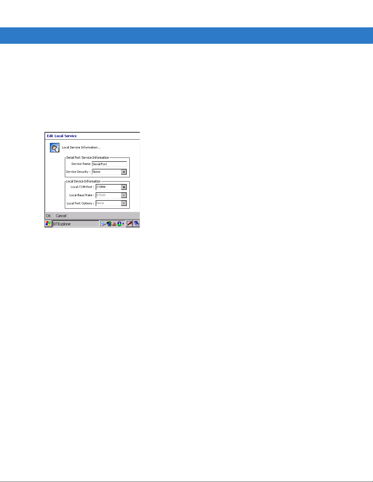
Using Bluetooth 3 - 25
Service Security Select the type of security from the drop-down list;
Support Group Ad-Hoc
Networking
Authenticate/Encrypt
Select to enable Ad-Hoc networking.
.
Serial Port Service
Serial port allows COM ports to be accessed by other Bluetooth devices.
Figure 3-35 Serial Port Service Window
None, Authenticate
or
Service Name Displays the name of the service.
Service Security Select the type of security from the drop-down list;
Authenticate/Encrypt
Local COM Port Select the COM port. Select COM1 to use a modem or other device that is connected to the
connector on the bottom of the mobile computer.
Local Baud Rate Select the communication baud rate.
Local Port Options Select the port option.
.
None, Authenticate
or
Headset Service
Serial port allows COM ports to be accessed by other Bluetooth devices.
Page 92

3 - 26 MC3000 User Guide
Figure 3-36 Headset Service Window
Service Name Displays the name of the service.
Security Tab
To adjust the security settings for an individual service, select the Services tab first, then select the individual
service, then
Figure 3-37 BTExplorer Settings - Security Tab
Use PIN Code (Incoming
Connecting)
PIN Code Enter the PIN code.
Encrypt Link On All Outgoing
Connections
Properties.
Select for automatic use of the PIN code entered in the
recommended not to use this automatic PIN code feature. See
more information.
Select to enable or disable encryption. Use encryption whenever possible.
PIN Code
text box. It is
Security on page 3-2
for
Discovery Tab
Use the Discovery tab to set and modify discovered devices.
Page 93

Using Bluetooth 3 - 27
Figure 3-38 BTExplorer Settings - Discovery Tab
Inquiry Length Sets the amount of time that the mobile computer takes to discover Bluetooth
devices in the area.
Name Discovery Mode Select either Automatic or manual.
Discovered Devices Deletes all discovered devices and link keys.
Virtual COM Port Tab
Use the Virtual COM Port tab to select the COM ports for Bluetooth communication.
Figure 3-39 BTExplorer Settings - Virtual COM Port Tab
COM4:Bluetooth Enable or disable COM Port 4.
COM5:Bluetooth Enable or disable COM Port 5
COM9:Bluetooth Enable or disable COM Port 9
NOTE If an application uses one of the COM ports assigned to Bluetooth, opening this port causes the Bluetooth
stack to activate and guide you through the connection process.
Page 94
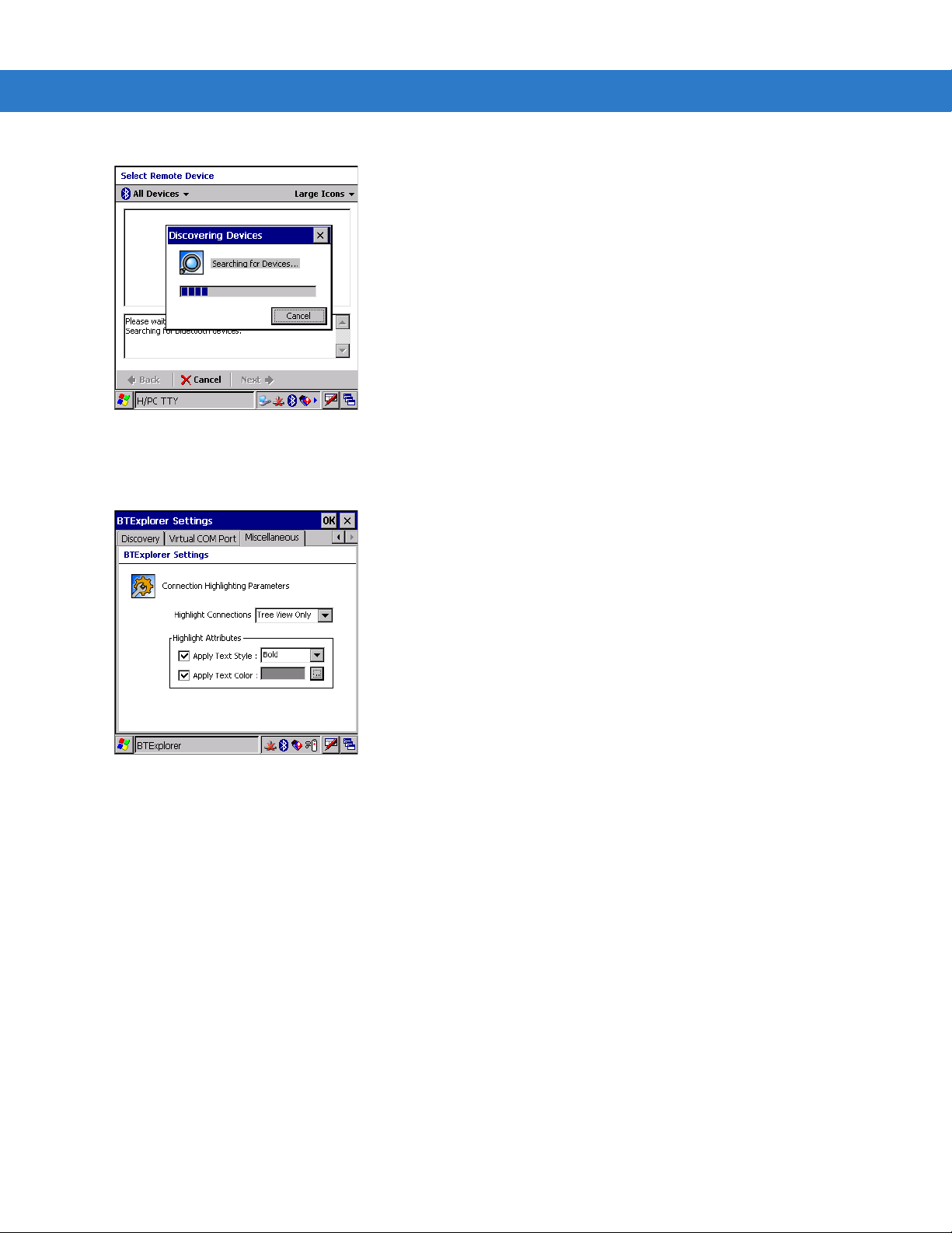
3 - 28 MC3000 User Guide
Figure 3-40 COM Port Connection
Miscellaneous Tab
Figure 3-41 BTExplorer Settings - Miscellaneous Tab
Highlight Connections Select the connection type to highlight when connected. In the Wizard Mode,
the only option is Favorites or None. In the Explorer Mode the options are
None, Tree View Only, List View Only
Apply Text Style Select the text style to be applied to the connection text.
Apply Text Color Select the text color to be applied to the connection text.
or
Tree and List View
.
Page 95

Chapter 4 Accessories
Introduction
The MC3000 accessories provide a variety of product support capabilities. Accessories include cradles, cables,
spare battery chargers and SD cards.
Cradles
• The Single Slot Serial/USB cradle charges the mobile computer main battery and/or a spare battery. It also
synchronizes the mobile computer with a host computer through either a serial or a USB connection.
• The Four Slot Charge Only cradle charges up to four mobile computers.
• The Four Slot Ethernet cradle charges up to four mobile computers and provides Ethernet communication.
Spare Battery Chargers
• Four Slot Spare Battery Charger charges up to four MC3000 spare batteries.
• UBC Adapter adapts the UBC2000 for use with the MC3000 batteries.
NOTE The accessory power supply regulatory compliance statements are provided in Table C-1 on page C-1.
Cables
The cables snap on to the mobile computer and are used to connect external devices to the mobile computer.
• USB client charge cable
• RS232 Charge cable
• O’Neil printer cable
• Zebra printer cable
• Monarch printer cable.
Page 96

4 - 2 MC3000 User Guide
SD Card
The SD card provides additional storage capacity for the mobile computer.
Plastic Holster
The Plastic Holster provides a clip on holder for the mobile computer.
Fabric Holster
The Fabric Holster provides a clip on holder for the mobile computer.
Single Slot Serial/USB Cradle
CAUTION Ensure that you follow the guidelines for battery safety described in Battery Safety Guidelines on page 7-1.
The Single Slot Serial/USB cradle:
• Provides 5.4VDC power for operating the mobile computer, charging the battery and charging a spare
battery.
• Provides a serial port and a USB port for data communication between the mobile computer and a host
computer or other serial devices (e.g., a printer).
• Synchronizes information between the mobile computer and a host computer. With customized or third party
software, it can also synchronize the mobile computer with corporate databases.
• Provides serial connection through the serial pass-through port for communication with a serial device, such
as a host computer. For communication setup procedures, refer to the MC3000 Integrator Guide.
• Provides USB connection through the USB pass-through port for communication with a USB device, such as
a host computer. For comm unication setup procedures, refer to the MC3000 Integrator Guide.
CAUTION Use only a Symbol approved power supply output rated 12 VDC and minimum 3.3 A. Use of an alternative
power supply will void the product warranty and may cause product damage. See Appendix C, Regulatory
for the power supply regulatory compliance statement.
Battery Charging
The Single Slot Serial/USB cradle can charge the mobile computer main battery and a spare battery
simultaneously.
To charge the mobile computer:
1. Slide the mobile computer into the mobile computer slot. The mobile computer amber Charge LED Indicator,
indicates the mobile computer battery charging status. The Standard Battery charges in less than four hours
and the Extended Life Battery charges in less than six hours. See Table 4-1 for charging status indications.
Page 97
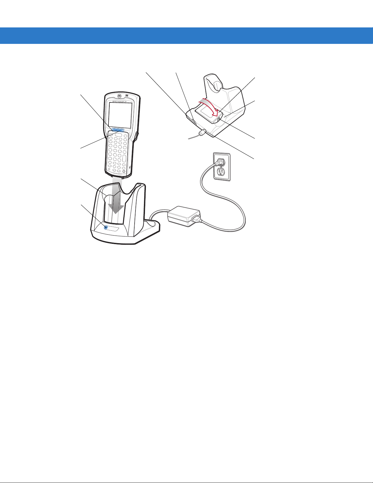
Accessories 4 - 3
Indicator
LED Bar
Mobile
Computer Slot
Spare Battery
Spare Battery
Charging
LED
Power Port
Serial Port
USB Port
Spare Battery
Charging Slot
Battery
Clip
Charge LED
Indicator
(amber)
Figure 4-1 Single Slot Serial/USB Cradle
2. When charging is complete, remove the mobile computer from the mobile computer slot.
To charge the spare battery:
1. Insert the spare battery into the spare battery charging slot, bottom first, and pivot the top of the battery down
onto the contact pins.
2. Gently press down on the battery to ensure proper contact.
3. The Spare Battery Cha rging LED (see F igure 4-1 on p age 4-3) indicates the spare battery charging status. The
Stan dard Battery charg es in less than four hours an d th e Extended Life Battery char ges in less th an six hours.
See Table 4-1 for charging status indications.
4. When charging is complete, press the battery clip and lift the battery out of the slot.
LED Charge Indications
The Single Slot Serial/USB cradle uses the mobile computer amber Charge LED Indicator to indicate the battery
charging status and the Spare Battery Charging LED to indicate spare battery charging status. See Table 4-1 for
charging status indications.
Page 98

4 - 4 MC3000 User Guide
Table 4-1 LED Charging Status Indicators
LED Indication
Mobile Computer Charging (LED on mobile computer)
Off Mobile computer not placed correctly in the cradle; cable not connected correctly;
Fast Blinking Amber Error in charging; check placement of mobile computer.
Slow Blinking Amber Mobile computer is charging.
Solid Amber Charging complete.
Spare Battery Charging (LED on cradle)
Off No spare battery in slot; spare battery not placed correctly; cradle is not powered.
Fast Blinking Amber Error in charging; check placement of spare battery.
charger is not powered.
Note: When the battery is initially inserted in the mobile computer, the amber LED flashes
once if the battery power is low or the battery is not fully inserted.
Slow Blinking Amber Spare battery is charging.
Solid Amber Charging complete.
Page 99
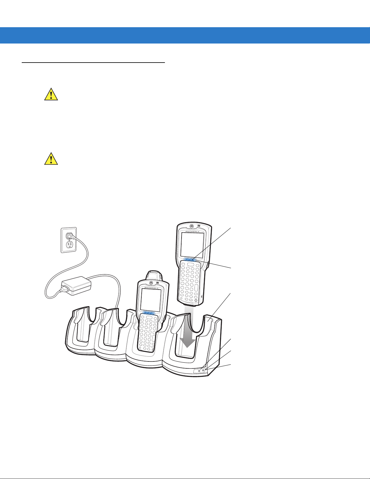
Four Slot Cradles
Scan/Charge Indicator LED Bar
Mobile Computer Slot
Charge LED Indicator (amber)
Speed LED (Ethernet Cradle Only)
Link LED (Ethernet Cradle Only)
Power LED (Charge Only Cradle)
CAUTION Ensure that you follow the guidelines for battery safety described in Battery Safety Guidelines on page 7-1.
There are two four slot cradles, Four Slot Charge Only cradle and Four Slot Ethernet cradle. The Four Slot
Ethernet cradle provides Ethernet communications. Both four slot cradles:
• Provide 5.4 VDC power for operating the mobile computer and charging the battery.
• Simultaneously charges up to four mobile computers.
CAUTION Use only a Symbol approved power supply output rated 12 VDC and minimum 9 A. Use of an alternative
Battery Charging
The four slot cradle can charge up to four mobile computers simultaneously. To charge the mobile computer:
Accessories 4 - 5
power supply will void the product warranty and may cause product damage. See Appendix C, Regulatory
for the power supply regulatory compliance statement.
1. Slide the mobile computer into the mobile computer slot.
Figure 4-2 Four Slot Cradles
2. The mobile computer amber Charge LED Indicator , indi cates the mobile computer ba ttery charging st atus. The
Stan dard Batter y usually charges in less th an four hour s a nd the Extended Li fe Batter y usually charges in less
than six hours. See Tab l e 4- 1 for charging status indications.
3. When charging is complete, remove the mobile computer from the cradle.
Page 100

4 - 6 MC3000 User Guide
LED Charge Indications
The Four Slot cradles use the mobile computer amber Charge LED Indicator to indicate the battery charging
status. See Table 4-1 on page 4-4 for charging status indications.
Power LED
The green Power LED (only on the Four Slot Charge Only cradle) lights to indicate that the Four Slot Charge Only
cradle is connected to a power source.
Speed LED
The green Speed LED (only on the Four Slot Ethernet cradle) lights to indicate that the transfer rate is 100 Mbps.
When it is not lit it indicates that the transfer rate is 10 Mbps.
Link LED
The yellow Link LED (only on the Four Slot Ethernet cradle) blinks to indicate activity, or stays lit to indicate that a
link is established. When it is not lit, it indicates that there is no link.
 Loading...