

Page 1
SURFboard
®
SB5100 Series
Cable Modem
Installation Manual
O
W
P
E
R
C
E
E
R
I
V
E
S
E
N
D
N
O
L
I
N
E
C
A
/
T
C
I
V
P
I
T
Y
A
T
N
S
D
B
Y
S
B
S
5
U
10
R
C
F
0
a
b
b
o
le
a
r
d
M
®
o
d
e
m
Page 2
CAUTION
RISK OF ELECTR IC SHOCK
TO REDUCE THE RISK OF ELECTRIC SHOCK,
CAUTION:
DO NOT REM OVE COVE R (OR BACK).
NO USER-SERVICEABLE PARTS INSIDE.
REFER SERVICING TO QUALIFIED SERVICE PERSONNEL.
Caution
These servicing instructions are for use by qualified personnel only. To reduce the risk of electrical shock, do not perform any servicing other
than that contained in the Installation and Troubleshooting Instructions unless you are qualified to do so. Refer all servicing to qualified service
personnel.
Special Symbols That Might Appear on the Equipment
This symbol indicates that dangerous voltage levels are present within the equipment. These voltages are not
insulated and may be of sufficient strength to cause serious bodily injury when touched. The symbol may also
appear on schematics.
This product was qualified under test conditions that included the use of the supplied cable between system
components. To be in compliance with regulations, the user must use this cable and install it properly.
Different types of cord sets may be used for connections to the main supply circuit. Use only a main line cord
that complies with all applicable product safety requirements of the country of use.
WARNING: TO PREVENT FIRE OR SHOCK HAZARD, DO NOT EXPOSE THIS APPLIANCE TO RAIN OR MOISTURE. THE APPARATUS
MUST NOT BE EXPOSED TO DRIPPING OR SPLASHING AND NO OBJECTS FILLED WITH LIQUIDS, SUCH AS VASES, MUST BE
PLACED ON THE APPARATUS.
CAUTION: TO PREVENT ELECTRICAL SHOCK, DO NOT CONNECT THE PLUG INTO AN EXTENSION CORD, RECEPTACLE, OR OTHER
OUTLET UNLESS THE BLADES CAN BE FULLY INSERTED WITH NO PART OF THE BLADES EXPOSED.
CAUTION: TO ENSURE REGULATORY AND SAFETY COMPLIANCE, USE ONLY THE PROVIDED POWER AND INTERFACE CABLES.
CAUTION: DO NOT OPEN THE CABLE MODEM. DO NOT PERFORM ANY SERVICING OTHER THAN THAT CONTAINED IN THE
INSTALLATION AND TROUBLESHOOTING INSTRUCTIONS UNLESS YOU ARE QUALIFIED TO DO SO. REFER ALL SERVICING TO
QUALIFIED SERVICE PERSONNEL.
Installation of this product must be in accordance with national wiring codes.
It is recommended that the customer install an AC surge arrestor in the AC outlet to which this device is connected. This is to avoid damaging
the equipment by local lightning strikes and other electrical surges.
Postpone cable modem installation until there is no risk of thunderstorm or lightning activity in the area. Avoid damaging the cable modem with
static by touching the coaxial cable connector when it is attached to the earth grounded coaxial cable TV wall outlet. Always first touch the
coaxial cable connector on the cable m odem when you are disconnecting or re-connecting your USB or Ethernet cable from the cable modem
or your PC.
To prevent overheating, do not block the ventilation holes on the sides of the cable modem or lay the cable modem on its side.
Page 3

FCC Compliance
This equipment has been tested and found to comply with the limits for a Class B digital device, pursuant to Part 15 of the FCC Rules. These
limits are designed to provide reasonable protection against harmful interference when the equipment is operated in a residential environment.
This equipment generates, uses, and can radiate radio frequency energy and, if not installed and used in accordance with the instructions, may
cause harmful interference to radio communications. However, there is no guarantee that interference will not occur in a particular installation. If
this equipment does cause harmful interference to radio or television reception, which can be determined by turning the equipment off and on,
the user is encouraged to try to correct the interference by one of the following measures:
Re-orient or relocate the receiving antenna
Increase the separation between the equipment and receiver
Connect the equipment into an outlet on a circuit different from that to which the receiver is connected.
Consult the dealer or an experienced radio/TV technician for help.
Changes or modification not expressl y approved by the party responsible for compliance could void the user’s authority to operate the
equipment.
Canadian Compliance
This Class B digital apparatus complies with Canadian ICES-003. Cet appareil numérique de la classe B est conforme á la norme NMB-003 du
Canada.
FCC Declaration of Conformity
According to 47CFR, Parts 2 and 15 for Class B Personal Computers and Peripherals; and/or CPU Boards and Power Supplies used with Class
B Personal Computers, Motorola, Inc. Broadband Communications Sector, 101 Tournament Drive, Horsham, PA 19044, 1-215-323-1000,
declares under sole responsibility that the product identifies with 47CFR Part 2 and 15 of the FCC Rules as a Class B digital d evice. Each
product marketed is identical to the representative unit tested and found to be compliant with the standards. Records maintained continue to
reflect the equipment being produced can be expected to be within the variation accepted, due to quantity production and testing on a statistical
basis as required by 47CFR 2.909. This device complies with Part 15 of the FCC rules. Operation is subject to the following two conditions:
(1) this device may not cause harmful interference, and (2) this device must accept all interference received, including interference that may
cause undesired operation. The above named party is responsible for ensuring that the equipment complies with the standards of 47CFR,
Paragraph 15.101 to 15.109.
The SURFboard cable modem meets one or more of the standards listed:
Declaration of Conformity
We
Motorola, Inc.
Declare under our sole responsibility that the
SURFboard Cable Modem Model SB5100 Series
To which the declaration relates is in conformity with one of the following standards:
EN55022 EN55024 EN60950 (3rd Edition)
CISPR 22 CISPR 24 IEC60950 (3rd Edition)
following the provisions of the Directive(s) of the Council of the European Union:
EMC Directive 89/336/EEC
Directive 93/68/EEC
Broadband Communications Sector
101 Tournament Drive
Horsham, PA, U.S.A.
Low Voltage Directive 73/23/EEC
This product was qualified under test conditions that included the use of the supplied cable between system components. To be in
compliance with regulations, the user must use this cable and install it properly.
Model Standards
SB5100 FCC Part 15, ICES-003, UL/C-UL 60950 (3rd Edition)
SB5100E EN55022, EN55024, EN60950 (3rd Edition), CISPR 22, CISPR 24, IEC60950 (3rd Edition)
SB5100i EN55022, EN55024, EN60950 (3rd Edition), CISPR 22, CISPR 24, IEC60950 (3rd Edition), FCC Part 15,
UL/C-UL 60950 (3
rd
Edition)
Page 4

Copyright © 2003 by Motorola, Inc.
All rights reserved. No part of this publication may be reproduced in any form or by any means or used to make any derivative work (such as
translation, transformation or adaptation) without written permission from Motorola, Inc.
Motorola reserves the right to revise this publication and to make changes in content from time to time without obligation on the part of Motorola
to provide notification of such revision or change. Motorola provides this guide without warranty of any kind, either implied or expressed,
including, but not limited to, the implied warranties of merchantability and fitness for a particular purpose. Motorola may make improvements or
changes in the product(s) described in this manual at any time.
Motorola, the stylized M logo, and SURFboard are registered trademarks and StormWatch and the SURFboard logo are trademarks of
Motorola, Inc.
Acrobat and Acrobat Reader are registered trademarks of Adobe Systems Incorporated.
Microsoft, Windows, and W indows Me are registered trademarks of Microsoft Corporation; Windows XP is a trademark of Microsoft Corporation.
Microsoft Windows screen shots are used by permission of Microsoft Corporation.
Macintosh, Quicktime and Quicktime logo are registered trademarks of Apple Computer, Inc.
UNIX is a registered trademark of the Open Group.
All other product or service marks are the property of their respective owners. © Motorola, Inc. 2003.
Page 5

Contents
Section 1
Introduction
Using This Manual............................................................................................................................................................................1-2
Document Conventions ...................................................................................................................................................................1-2
If You Need Help ...............................................................................................................................................................................1-3
Calling for Repairs............................................................................................................................................................................1-3
Section 2
Overview
Top and Front Panel.........................................................................................................................................................................2-2
Rear Panel .........................................................................................................................................................................................2-4
Section 3
Installation and Operation
Before You Begin .............................................................................................................................................................................3-2
Installing a Single User ....................................................................................................................................................................3-3
Setting Up a USB Driver...................................................................................................................................................................3-5
Setting Up a USB Driver for Windows 98 ..............................................................................................................................3-5
Setting Up a USB Driver for Windows 2000 ........................................................................................................................3-10
Setting Up a USB Driver for Windows Me ...........................................................................................................................3-14
Setting Up a USB Driver for Windows XP ...........................................................................................................................3-16
Configuring the Computer for TCP/IP ..........................................................................................................................................3-18
Configuring for TCP/IP in Windows 95, Windows 98, and Windows Me..........................................................................3-18
Configuring for TCP/IP in Windows 2000............................................................................................................................3-21
Configuring for TCP/IP in Windows XP...............................................................................................................................3-25
Verifying an IP Address .................................................................................................................................................................3-27
Verifying an IP Address in Windows 95, Windows 98, and Windows Me........................................................................3-27
Verifying an IP Address in Windows 2000 and Windows XP............................................................................................3-29
Renewing an IP Address................................................................................................................................................................3-31
Installing Multiple Users ................................................................................................................................................................3-31
Removing the USB Driver..............................................................................................................................................................3-33
Removing the USB Driver from Windows 98 or Windows Me ..........................................................................................3-33
Removing the USB Driver from Windows 2000 ..................................................................................................................3-37
Removing USB Driver from Windows XP............................................................................................................................3-41
SURFboard Cable Modem Installation Manual
Page 6

ii Contents
Recovering from Windows 98 or Win98_SE Installation Errors................................................................................................ 3-46
Remove Program................................................................................................................................................................... 3-46
Solutions................................................................................................................................................................................ 3-47
Solution 1........................................................................................................................................................................ 3-47
Solution 2........................................................................................................................................................................ 3-48
Setting the Frequency Using StormWatch.................................................................................................................................. 3-49
Section 4
HTML User Interface
Section 5
Troubleshooting
Appendix A
Specifications
Downstream......................................................................................................................................................................................A-1
Upstream...........................................................................................................................................................................................A-1
General..............................................................................................................................................................................................A-1
Appendix B
Event Log Messages
Event Message Format....................................................................................................................................................................B-1
Priority Levels ..................................................................................................................................................................................B-1
Predefined Log Messages...............................................................................................................................................................B-2
SP-RFI_I05-991105 – Error Codes for MAC Management Messages .................................................................................B-2
SYNC Timing Synchronization .........................................................................................................................................B-2
UCD Upstream Channel Descriptor .................................................................................................................................B-2
MAP Upstream Bandwidth Allocation...............................................................................................................................B-2
RNG-RSP Ranging Response .........................................................................................................................................B-3
RNG-REQ Ranging Request............................................................................................................................................B-3
REG-REQ Registration Request ......................................................................................................................................B-3
REG-RSP Registration Response....................................................................................................................................B-5
UCC-REQ Upstream Channel Change Request..............................................................................................................B-5
UCC-RSP Upstream Channel Change Response ...........................................................................................................B-6
DHCP CM Net Configuration Download and Time of Day ...............................................................................................B-6
Baseline Privacy...............................................................................................................................................................B-7
SURFboard Cable Modem Installation Manual
Page 7

Contents iii
SURFboard Cable Modem Specific Log Messages............................................................................................................. B-7
Baseline Privacy .............................................................................................................................................................. B-7
DHCP / TFTP................................................................................................................................................................. B-10
Filtering .......................................................................................................................................................................... B-13
Driver.............................................................................................................................................................................. B-19
Registration.................................................................................................................................................................... B-20
Miscellaneous ................................................................................................................................................................ B-21
Acquisition...................................................................................................................................................................... B-22
Unit Update .................................................................................................................................................................... B-23
=
Figures
Figure 2-1 SURFboard cable modem data path ...........................................................................................................................2-1
Figure 2-2 Front panel LEDs and Standby button........................................................................................................................2-2
Figure 2-3 Rear-panel connections and LEDs..............................................................................................................................2-3
Figure 3-1 Cable connections ........................................................................................................................................................3-3
Figure 3-2 Ethernet - Multiple users ............................................................................................................................................3-31
Figure 3-3 Ethernet - Two users with two interfaces .................................................................................................................3-31
Figure 3-4 Ethernet - Multiple users with two interfaces...........................................................................................................3-32
Figure 4-1 Configuration Manager Help window..........................................................................................................................4-1
Figure 4-2 Configuration Manager Startup window.....................................................................................................................4-2
Figure 4-3 Configuration Manager Signal window.......................................................................................................................4-3
Figure 4-4 Configuration Manager Addresses window ...............................................................................................................4-4
Figure 4-5 Configuration window...................................................................................................................................................4-5
Figure 4-6 Configuration Manager Logs window.........................................................................................................................4-6
Tables
Table 2-1 Front-panel LEDs and Standby button.........................................................................................................................2-2
Table 2-2 Rear-panel connections and LEDs ...............................................................................................................................2-3
Table 5-1 Troubleshooting guidelines...........................................................................................................................................5-1
Table 5-2 Troubleshooting checklist .............................................................................................................................................5-2
Table B-1 Priority level....................................................................................................................................................................B-1
SURFboard Cable Modem Installation Manual
Page 8
Section 1
Introduction
The Motorola® SURFboard SB5100 series cable modem provides a link from a home or business
computer to a high-speed DOCSIS or Euro-DOCSIS 2.0, 1.1, or 1.0 compliant data network. This
network provides a downstream data transfer rate up to 38 Mbps in a single 6 MHz channel
(55 Mbps in a 8 MHz channel for Euro-DOCSIS) using 64 QAM and 256 QAM technologies. The
SURFboard cable modem provides a USB or Ethernet connection.
The features of the SURFboard cable modem include:
®
! Windows
! USB interface for direct connection to USB-equipped computers
! 10/100Base-T Ethernet port supporting up to 32 users
! Standby switch on top of unit
! Remote management through SNMP, internal web pages, or StormWatch
! Automatic configuration and address assignment
98, Windows® 2000, Windows Me®, and Windows XP™ based USB support
™
Diagnostic Suite
! Software upgrades over the network
! Compatibility with Windows, Macintosh
TCP/IP
! Extensive event logs for troubleshooting
®
, and UNIX
®
operating system computers running
SURFboard Cable Modem Installation Manual
Page 9

1-2 Introduction
Using This Manual
The following sections provide information and instructions to install, configure, and operate the
SURFboard cable modem:
Section 1 Introduction provides a product description, the technical help line, and repair/return
information.
Section 2 Overview describes the functions of the SURFboard cable modem and identifies the
front-panel LEDs and the rear-panel connectors.
Section 3 Installation and Operation provides instructions on how to install the SURFboard cable
modem.
Section 4 HTML User Interface provides information on the user interface windows.
Section 5 Troubleshooting provides troubleshooting tips.
Appendix A Specifications provide the technical specifications.
Appendix B Event Log Messages provides a description of the format and field codes of the
diagnostic events log.
Abbreviations
and Acronyms
The Abbreviations and Acronyms list contains the full spelling of the short forms used in
this manual.
Document Conventions
Before you begin using the SURFboard cable modem, familiarize yourself with the stylistic
conventions used in this manual:
Bold type
SMALL CAPS
Italic type
KEY+KEY
* (asterisk)
(asterisk)
(asterisk)(asterisk)
Indicates text that you must type exactly as it appears or indicates a default value
Denotes silk screening on the equipment, typically representing front- and rear-panel controls
and input/output (I/O) connections, and LEDs
Denotes a displayed variable, a variable that you must type, or is used for emphasis
Key combinations indicating that you hold down the first key and then press the second key
Indicates that several versions of the same model number exist and the information applies to
all models; when the information applies to a specific model, the complete model number is
given
SURFboard Cable Modem Installation Manual
Page 10

Introduction 1-3
If You Need Help
If you need assistance while working with the SURFboard cable modem, contact the Motorola
Technical Response Center (TRC):
! Inside the U.S.A.: 1-888-944-HELP (1-888-944-4357)
! Outside the U.S.A.: 1-215-323-0044
! Online: http://www.motorola.com/broadband
, click HTML/Modem Version, click
Customer Support, then click Web Support.
The TRC is open from 8:00 AM to 7:00 PM Eastern Time, Monday through Friday and 10:00 AM
to 6:00 PM Eastern Time, Saturday. When the TRC is closed, emergency service only is
available on a call-back basis. Web Support offers a searchable solutions database, technical
documentation, and low priority issue creation/tracking 24 hours per day, 7 days per week.
Calling for Repairs
If repair is necessary, call the Motorola BCS Repair Facility at 1-800-227-0450 for a Return for
Service Authorization (RSA) number before sending the unit. The RSA number must be
prominently displayed on all equipment cartons. The Repair Facility is open from 8:00 AM to
5:00 PM Central Time, Monday through Friday.
When calling from outside the United States, use the appropriate international access code and
then call 956-541-0600 to contact the Repair Facility.
When shipping equipment for repair, follow these steps:
1 Pack the unit securely.
2 Enclose a note describing the exact problem.
3 Enclose a copy of the invoice that verifies the warranty status.
4 Ship the unit PREPAID to the following address:
Motorola Corporation
Broadband Communications Sector
Attn: RSA #___________
5964 E. 14
th
Street
Brownsville, TX 78521
SURFboard Cable Modem Installation Manual
Page 11
Section 2
Overview
The SURFboard cable modem delivers digital multimedia content in a two-way transmission
system. It provides access to a cable data network, which provides access to the Internet and
World Wide Web.
The SURFboard cable modem is authorized by a cable modem terminations system (CMTS) for
use on the network and automatically configures itself with parameters received from the
CMTS or headend. When the SURFboard cable modem is powered on, it:
! Scans the frequency spectrum to locate the data frequency and automatically locks on to the
channel.
! Searches for a message containing the upstream parameters such as frequency, modulation,
symbol rate, and forward error correction (FEC) format.
! Transmits a message to the CMTS requesting additional information enabling network
connection.
! Establishes Internet Protocol (IP) connectivity using Dynamic Host Configuration Protocol
(DHCP)
! Receives a configuration file using the Trivial File Transfer Protocol (TFTP). This file
contains additional parameters required by the SURFboard cable modem.
! Registers with the CMTS and is authorized to use the network.
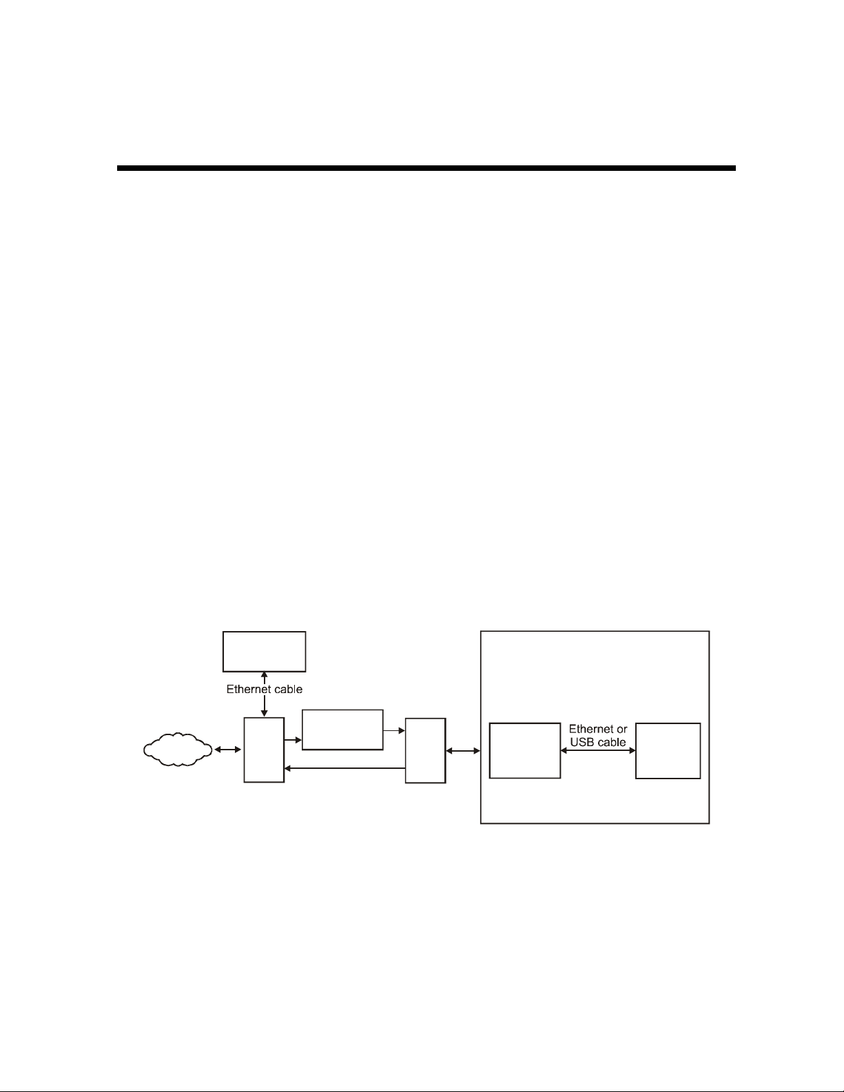
Figure 2-1 illustrates the SURFboard cable modem data path:
Figure 2-1
SURFboard cable modem data path
Internet
Network
management
services
IF
CMTS
Upconverter
RF
HFC plant
RF
Diplex
filter
RF
SURFboard
Customer premises
external
cable
modem
equipment
Client PC
The SURFboard cable modem supports 64 QAM and 256 QAM signals that are necessary for the
DOCSIS/Euro-DOCSIS data network. This network carries IP data in standard MPEG-2
packets. The RF downstream receives data at rates up to 38 Mbps (55 Mbps for Euro-DOCSIS)
and the RF upstream transfers data rates of up to 30 Mbps. The actual speeds will vary; speeds
of 30 Mbps are only attainable with A-TDMA or S-CDMA technology.
SURFboard Cable Modem Installation Manual
Page 12
2-2 Overview
1
The SURFboard cable modem provides an HTML user interface to:
! Monitor the cable modem and data signals
! Troubleshoot network connections
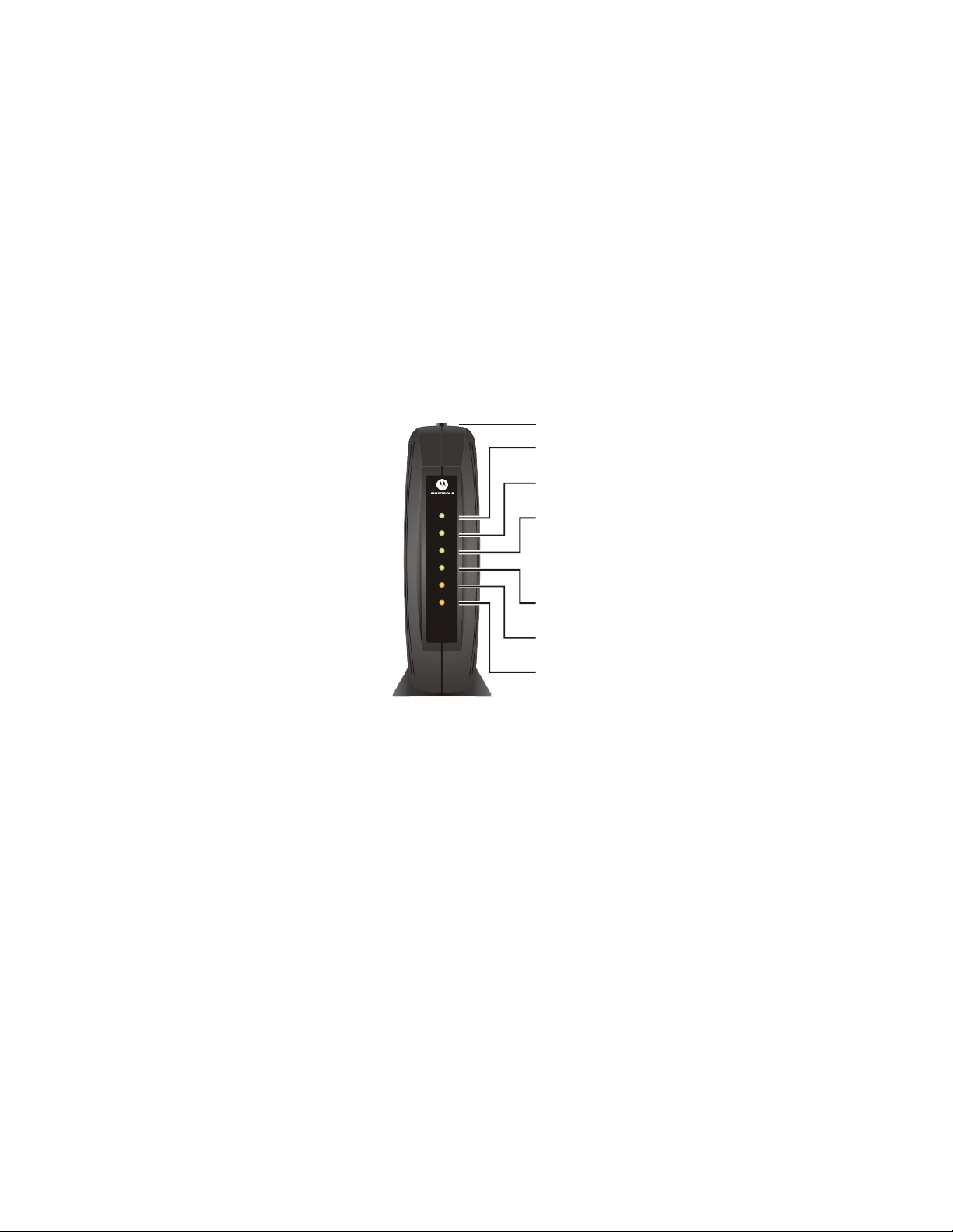
Top and Front Panel
The six front-panel LEDs provide status and activity information. The Standby button enables
the subscriber to disconnect the Ethernet and USB interfaces from the cable modem network.
The LEDs and Standby button are illustrated in Figure 2-2:
Figure 2-2
Front panel LEDs and Standby button
2
3
W
E
R
O
P
E
R
S
N
O
A
/
C
P
A
T
S
SB5100
SURFboard®
Cable Modem
E
I
C
V
E
N
E
D
L
I
N
E
T
C
I
V
I
T
Y
N
D
B
Y
4
5
6
7
Table 2-1 describes the front-panel LEDs and Standby button:
Table 2-1
Front-panel LEDs and Standby button
Key Item Description
1
Standby
Button
Press this button to suspend the Internet connection (Ethernet and USB ports remain active
for the local area network). When the Standby button is activated, all other LEDs turn off.
Press this button again to enable the channel connections for transmitting and receiving
data.
The Standby button offers Internet security.
SURFboard Cable Modem Installation Manual
Page 13

Overview 2-3
Key Item When Flashing When On
2 Power
3 Receive
4 Send
5 Online
6 PC/
Activity
7 Standby
Startup diagnostics in process. The cable modem is powered on.
Scanning for a receive (downstream)
channel connection.
Scanning for a send (upstream) channel
connection.
Scanning for a network configuration
server connection.
Transmitting or receiving data. A device, such as a computer or hub, is
This light does not flash. Press the Standby button and the light is on
The downstream channel is connected.
The upstream channel is connected.
The network connection is acquired.
connected to the USB or Ethernet connectors on
the back panel.
indicating the Internet service is suspended. The
connections to the Local Area Network remain
active. When this light is on, all other lights are
off. The Standby button offers added Internet
security.
During normal operation, the Power, Receive, Send, and Online lights are on and the
PC/Activity light flashes when the cable modem is transferring data.
SURFboard Cable Modem Installation Manual
Page 14
2-4 Overview
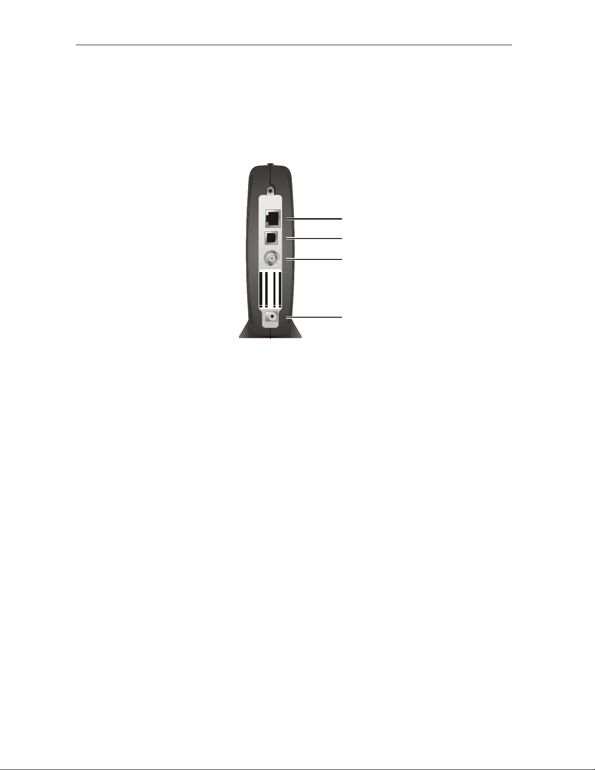
Rear Panel
The SURFboard cable modem rear panel provides the cabling connectors, status LEDs, and
power plug as illustrated in Figure 2-3:
Figure 2-3
Rear-panel connections and LEDs
ETHERNET
1
USB
CABLE
USB CPE MAC ID :ABDCEF0 12345
S/N: PPPP MMYJJJSSSSS CAABBCCCC
HFC MAC ID: ABCDEF012345
CUSTOMER S/ N:BCDF GHJKLMNP
2
3
+12VDC
4
Table 2-2 describes the SURFboard cable modem rear-panel connections and LEDs:
Table 2-2
Rear-panel connections and LEDs
Key Item Description
1
2
3
4
ETHERNET The Ethernet port provides a connection to Ethernet equipped computers using a cable
terminated with an RJ-45 connector.
USB This port provides a direct connection to USB equipped computers.
CABLE This port provides a connection to the coaxial cable outlet.
+12VDC This connector provides power to the cable modem.
SURFboard Cable Modem Installation Manual
Page 15
Section 3
Installation and Operation
This section provides instructions for cabling all SURFboard cable modem models and checking
their operation.
To complete the installation, you must:
! Connect the cables
! Configure the subscriber’s computer
Avoid damaging the SURFboard cable
modem or your PC with static electricity.
ETHERNET USB CABLE
USB CPE MAC ID:ABDCEF012345
S/N: PPPPMMYJJJSSSSSCAABBCCCC
HFC MAC ID: ABCDEF012345
CUSTOMER S/N:BCDFGHJKLMNP
+12VDC
To release any static charges, btouch the
coaxial cable connection on the modem
efore connecting or disconnecting the USB
or Ethernet cables.
Postpone SURFboard cable modem installation until there is no risk of thunderstorm or
lightning activity in the area.
SURFboard Cable Modem Installation Manual
Page 16

3-2 Installation and Operation
Before You Begin
Before you begin the installation, take a few minutes to review the installation information,
gather the required items, and complete the tasks listed below to make the installation as quick
and easy as possible:
1 Verify that the following items are included with the SURFboard cable modem:
Power adapter
SURFboard cable
modem CD-ROM
10/100Base-T
Ethernet cable
USB cable
Acquire the following items that are not included with the SURFboard cable modem:
2
75-ohm coaxial
TV cable with F-type
connectors
Laptop or PC
with TCP/IP and
HTML browser
RF splitter
Connects the SURFboard cable modem to the AC electrical outlet
Contains the User Guide and USB drivers
Required to connect an Ethernet computer port to the cable modem
Required to connect a USB-equipped computer to the cable modem
Required to connect the SURFboard cable modem to the nearest cable outlet
Required to access the internal web server for diagnostics
You may need a 5-900 MHz RF splitter if there is a TV connected to the cable
outlet.
Determine if you are installing a single user or a multiple user configuration. Verify that the
3
subscriber’s computer has:
# A USB connector for installing a single user configuration.
# For a single user connecting to the USB port, be sure to disable the Legacy USB Support
in BIOS. The SURFboard cable modem does not support Legacy USB architecture. Refer
to the subscriber’s system information to access the BIOS of the subscriber’s computer.
# An Ethernet card for installing a multiple user configuration (can be used for single user
in place of a USB). It must be installed before installing the cable modem.
SURFboard Cable Modem Installation Manual
Page 17
Installation and Operation 3-3
A
A
A
A
A
A
A
/
Installing a Single User
You can connect a single user to a SURFboard cable modem using the USB or Ethernet port.
Allow 5 to 30 minutes to power up the first time because the SURFboard cable modem must find
and lock on the appropriate channels for communications. To install the SURFboard cable
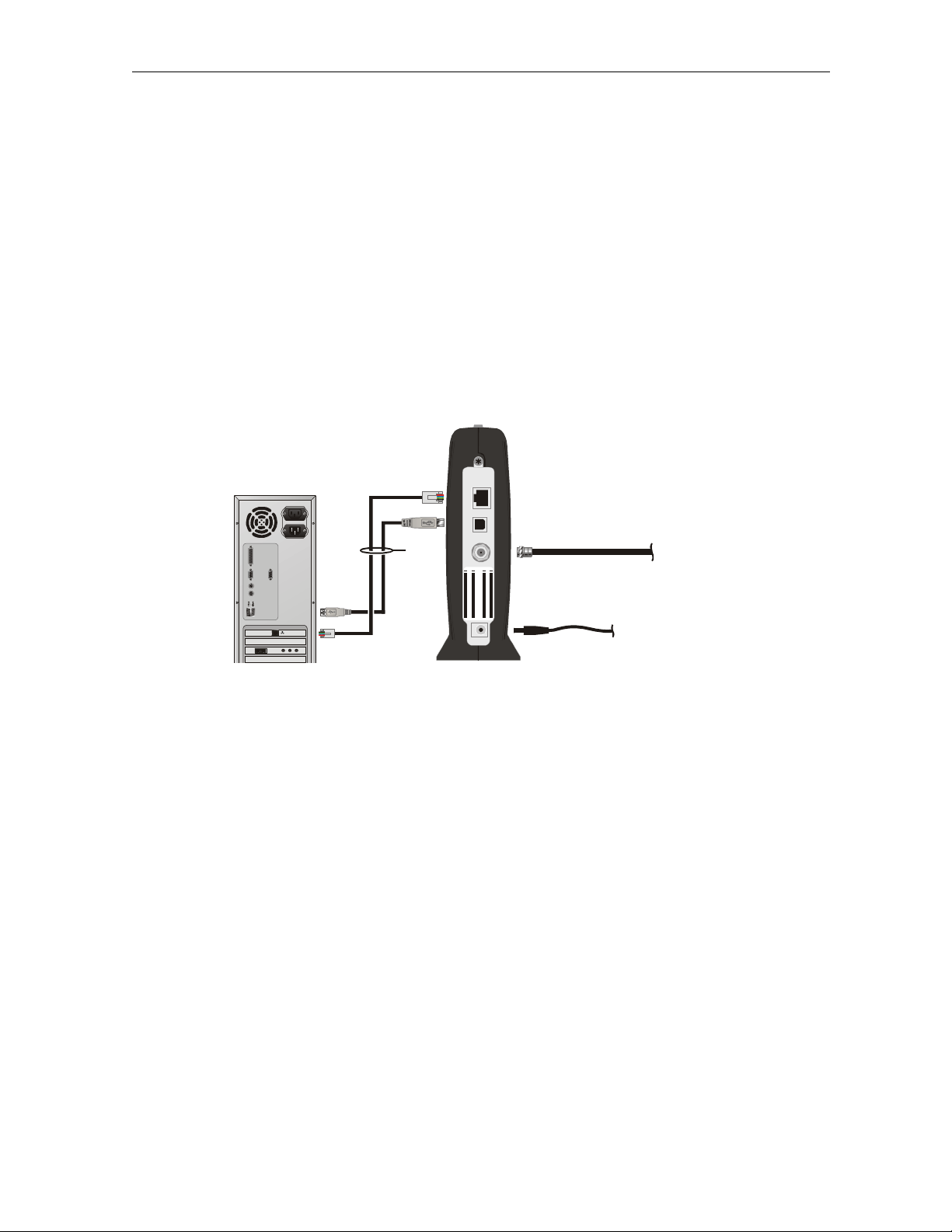
modem for a single user:
1 Be sure the subscriber’s computer is on and the cable modem is unplugged.
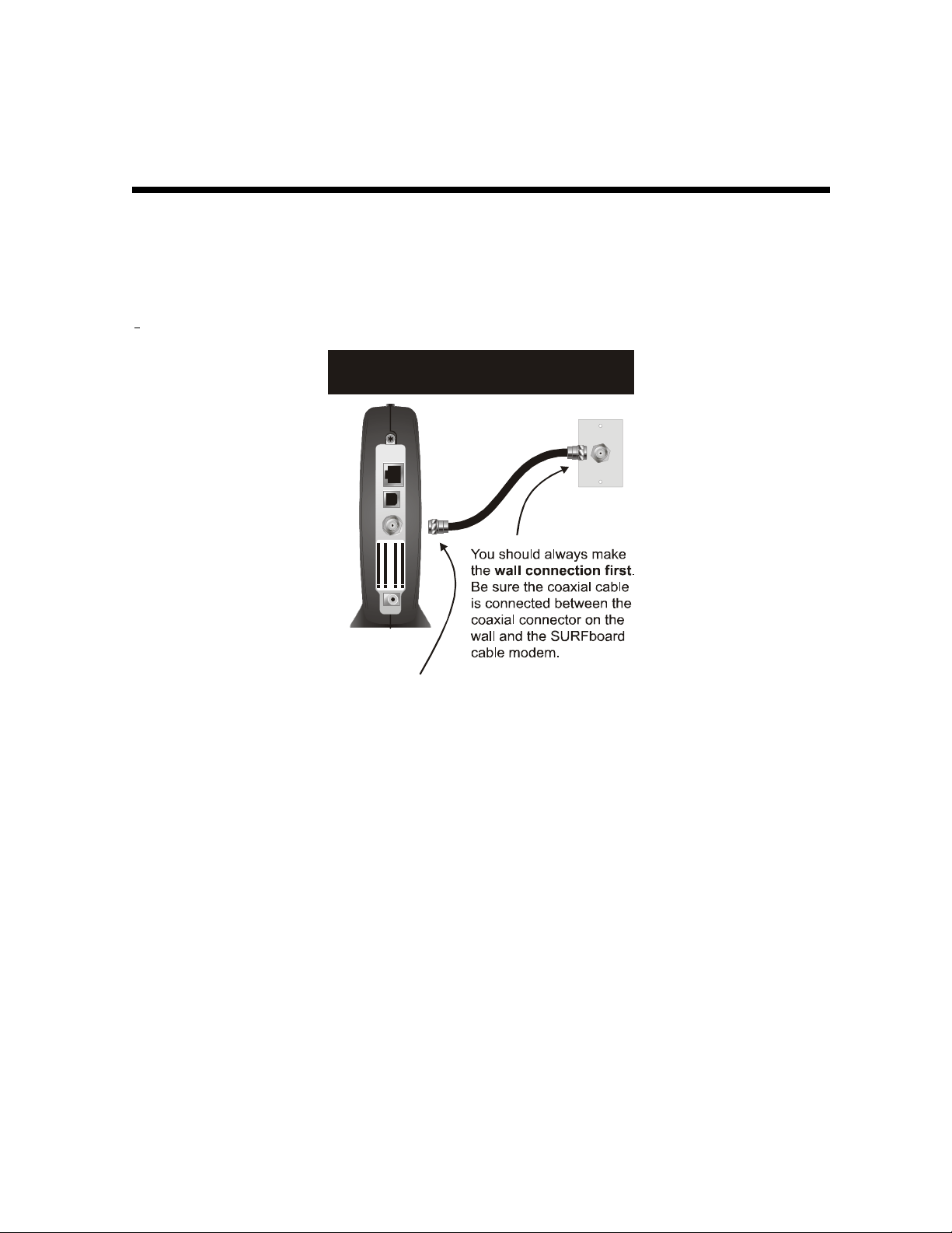
2 Connect one end of the coaxial cable to the cable outlet or splitter (Always make the wall
connection first). Connect the other end of the coaxial cable to the CABLE connector on the
cable modem. Hand-tighten the connectors to avoid damaging them. Figure 3-1 illustrates
the cable connections:
Figure 3-1
Cable connections
ETHERNET USB C
To
Ethernet
or USB
BLE
USBCPE M
HFCM
S/N: PPPPMMYJJJSSSSSC
CUSTOMER S
C ID:
C ID:
N:BCDFGHJKLMNP
BCDEF012345
BDCEF012345
BBCCCC
+12VDC
To
power
outlet
To c ab l e
outlet
3 Insert the SURFboard Cable Modem CD-ROM into the CD-ROM drive.
4 Plug the power cord into the +12VDC connector on the cable modem and the electrical
outlet. This turns the SURFboard cable modem on. The cable modem does not need to be
unplugged when not in use.
5 Check that the LEDs on the front of the cable modem cycle through this sequence:
POWER flashes during the self-test and changes to solid green when the self-test is
#
successfully complete.
RECEIVE flashes while scanning for the receive channel and changes to solid green when
#
the receive channel is locked.
SEND flashes while scanning for the send channel and changes to solid green when the
#
send channel is locked.
ONLINE flashes while the cable modem downloads configuration data and changes to
#
solid green when the download is complete. Configuration data includes the DHCP
server IP address, configuration, and time and date stamp.
SURFboard Cable Modem Installation Manual
Page 18

3-4 Installation and Operation
# If an error occurs:
When What occurs Provides
During power up
During normal
operation
Specific LEDs are off. For example,
if the downstream channel is not
acquired, the
from flashing to off.
The SURFboard cable modem
automatically loads configuration
updates.
The LED corresponding to the
failure is off.
For example, if the downstream
channel is lost, the
goes from on to off.
RECEIVE LED goes
RECEIVE LED
Immediate feedback as to where
the problem has occurred.
The SURFboard cable modem
automatically reboots if the IP
address and the cable modem
configuration file is not found.
By noting the LED status, you can
determine the source of the
problem.
For more information on errors, refer to Section 5, “Troubleshooting”.
It is not necessary to turn the cable modem off when it is not in use.
6 Connect the computer to the cable modem using the USB or Ethernet:
USB: Be sure the SURFboard Cable Modem CD-ROM is inserted in your CD-ROM drive.
Connect the USB cable to the USB port on the cable modem. Connect the other end to the
USB port on your computer. Then perform one of following:
# “Setting Up a USB Driver for Windows 98,” on page 3-5
# “Setting Up a USB Driver for Windows 2000,” on page 3-10
# “Setting Up a USB Driver for Windows Me,” on page 3-14
# “Setting Up a USB Driver for Windows XP,” on page 3-16
You can upgrade the USB drivers from the Internet. For information, check our website
http://www.motorola.com/broadband.
Ethernet: Connect the 10/100Base-T Ethernet cable to the SURFboard cable modem
connector marked
ETHERNET and the other end to the Ethernet jack on the back of the
computer. Ethernet users do not need to set up USB.
7 Configure TCP/IP using one of the following:
# “Configuring for TCP/IP in Windows 95, Windows 98, or Windows Me,” on page 3-18
# “Configuring for TCP/IP in Windows 2000,” on page 3-21
# “Configuring for TCP/IP in Windows XP,” on page 3-25
# The instructions in your Macintosh or UNIX user manual
SURFboard Cable Modem Installation Manual
Page 19
Installation and Operation 3-5
Setting Up a USB Driver
The following subsections provide instructions for setting up a USB driver for Windows 98,
Windows 2000, Windows Me, and Windows XP.
Setting Up a USB Driver for Windows 98
To set up a USB driver for Windows 98:
1 Be sure the SURFboard Cable Modem CD-ROM is inserted in your CD-ROM drive before
you plug in the USB cable.
This CD contains the USB drivers and must be inserted and read by the PC before you
connect the cable modem to the PC.
2 Be sure the disc load activity is complete before plugging in the USB cable.
System files are needed when loading the USB drivers. These files may already be on the
PC or you may be required to load them from the Microsoft CD that came with the
subscriber’s PC.
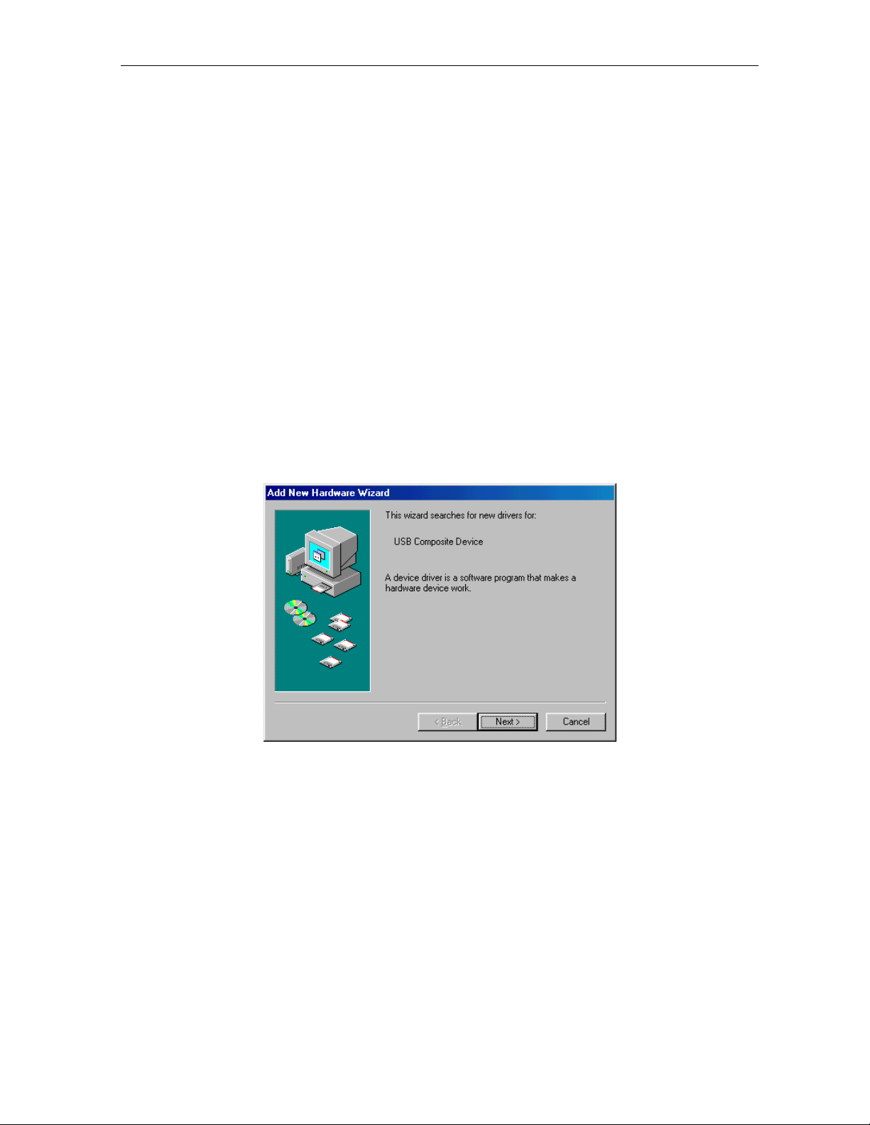
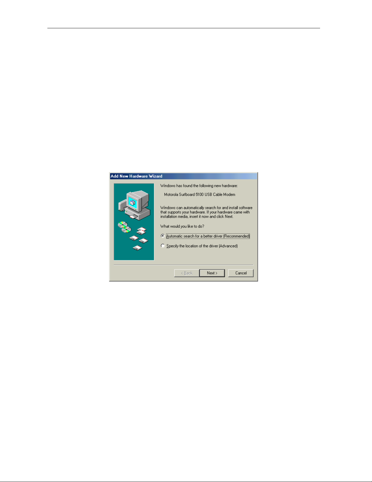
The PC automatically recognizes the USB connection and after several seconds, the
following window is displayed:
Although your SURFboard cable modem model number may be different than in the images
in this manual, the procedure is the same.
SURFboard Cable Modem Installation Manual
Page 20
3-6 Installation and Operation
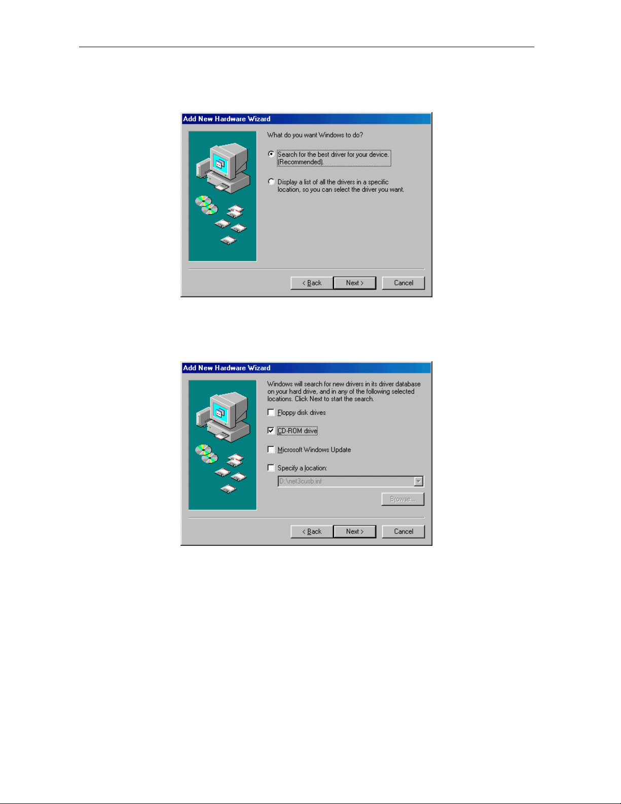
Click Next and the following window is displayed:
3
4 Ensure that the Search for the best driver for your device is selected as shown on the
window above.
5 Click Next, and the window below is displayed showing a location:
6 Ensure that the CD-ROM drive is the only box checked as shown in the window above.
7 Click Next.
If the computer successfully locates the driver, skip to step 11.
SURFboard Cable Modem Installation Manual
Page 21
Installation and Operation 3-7
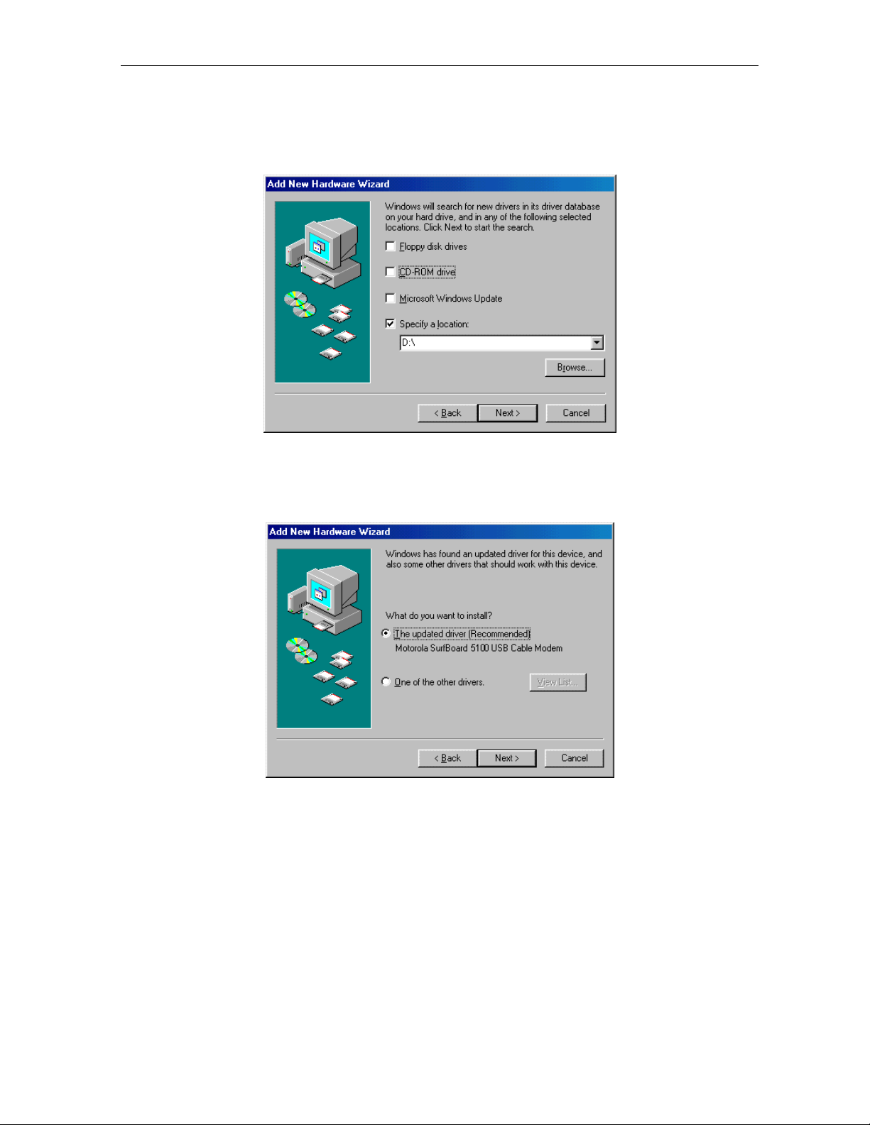
If the computer does not locate the driver, the previous window is displayed again. Select
8
Specify a location and type the location of your CD-ROM drive:
In this example, to load the driver successfully, you may need to click Browse to manually
select the NetMotCM.sys files on the CD-ROM.
9 Click Next to display the following window:
10 Select the updated driver... and click Next.
If the window above is not displayed, verify that the SURFboard Cable Modem CD-ROM is
properly inserted in the CD-ROM drive. If you still cannot find the correct driver file, click
Cancel to cancel the installation and perform the procedure for “Removing the USB Driver
from Windows 98 or Windows Me” on page 3-33 and then repeat this procedure.
SURFboard Cable Modem Installation Manual
Page 22
3-8 Installation and Operation
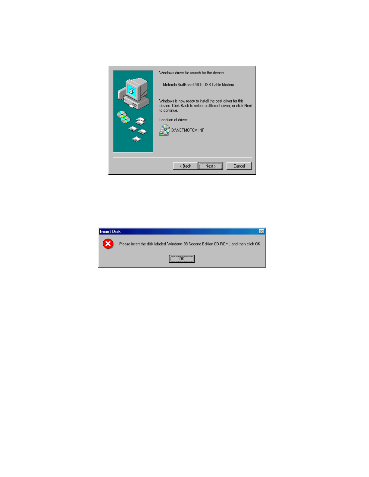
When the window below is displayed, click Next.
11
If a window with the message Copying Files... displays and asks for your CD-ROM drive,
type your CD-ROM drive letter (for example, “D:”) and click OK.
If an Insert Disk window similar to the one below is displayed, Windows 98 system files are
needed to complete the installation. To install the files, insert your Windows 98 CD-ROM in
the CD-ROM drive and click OK.
Although your SURFboard cable modem model number may be different than in the images
in this manual, the procedure is the same.
SURFboard Cable Modem Installation Manual
Page 23
Installation and Operation 3-9
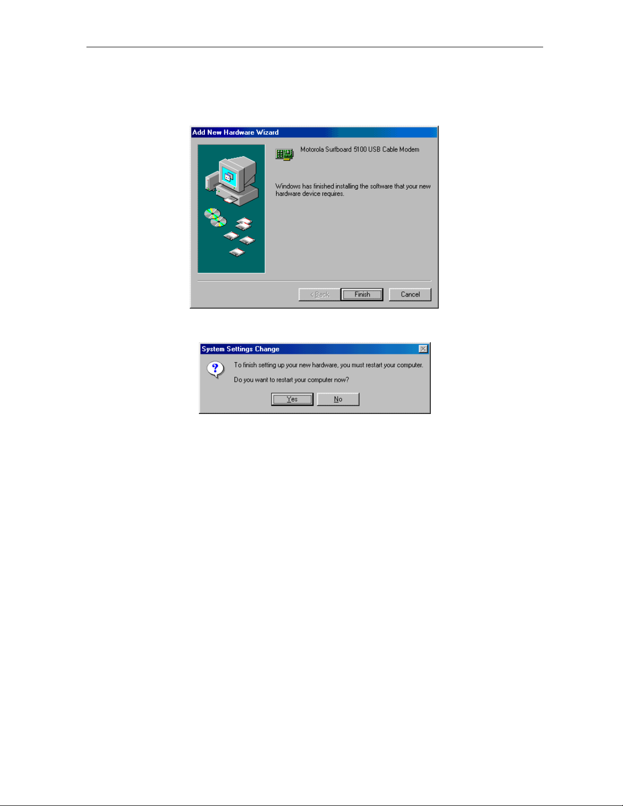
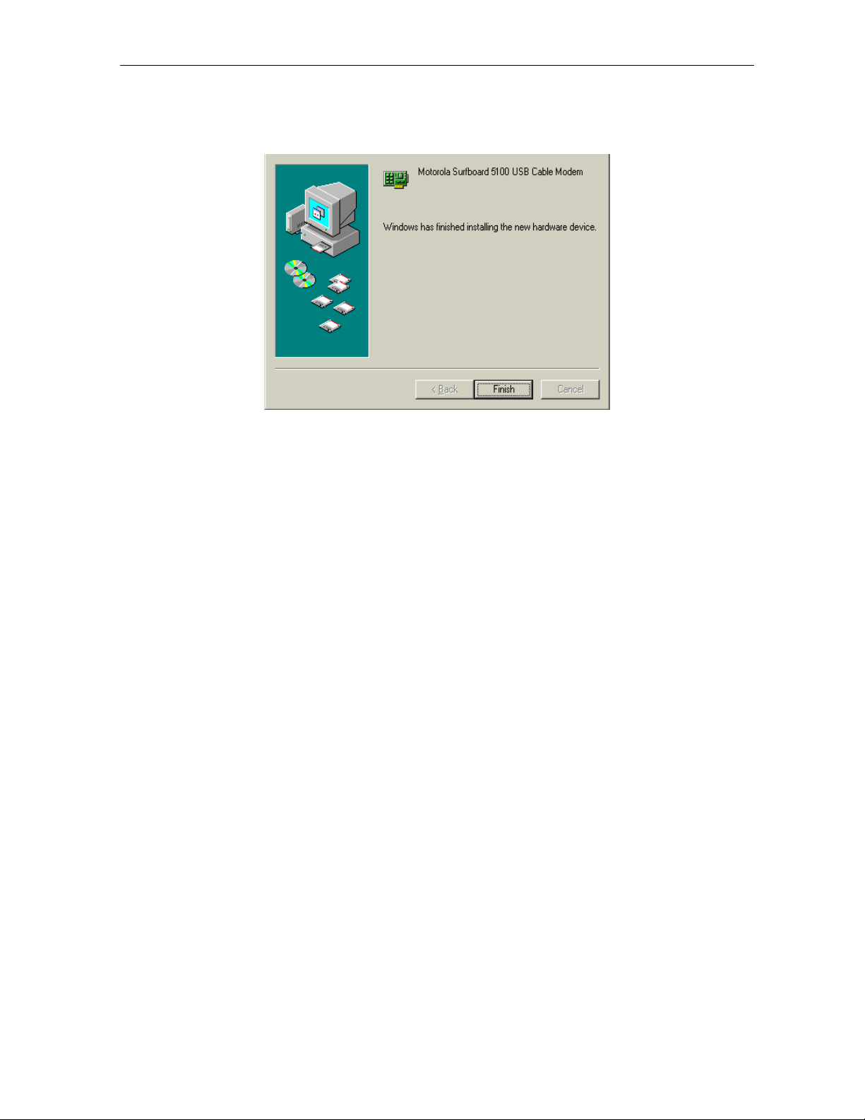
After all the necessary files are loaded, the window below is displayed confirming a
successful installation:
12 Click Finish. The window below is displayed:
13 Click Yes to restart your computer.
When you have successfully finished setting up the USB driver, you can continue with
“Configuring for TCP/IP in Windows 95, Windows 98, or Windows Me,” on page 3-18
If you have difficulties setting up the USB driver, perform the procedure for “Removing the USB
Driver from Windows 98 or Windows Me” on page 3-33, and then repeat this procedure.
SURFboard Cable Modem Installation Manual
Page 24
3-10 Installation and Operation
Setting Up a USB Driver for Windows 2000
To set up a USB driver for Windows 2000:
1 Be sure the SURFboard Cable Modem CD-ROM is inserted in your CD-ROM drive before
you plug in the USB cable.
This CD contains the USB drivers and must be inserted and read by the PC before you
connect the cable modem to the PC.
2 Be sure disc load activity is complete before plugging in the USB cable.
System files are needed when loading the USB drivers. These files may already be on the
PC or you may be required to load them from the Microsoft CD that came with the
subscriber’s PC.
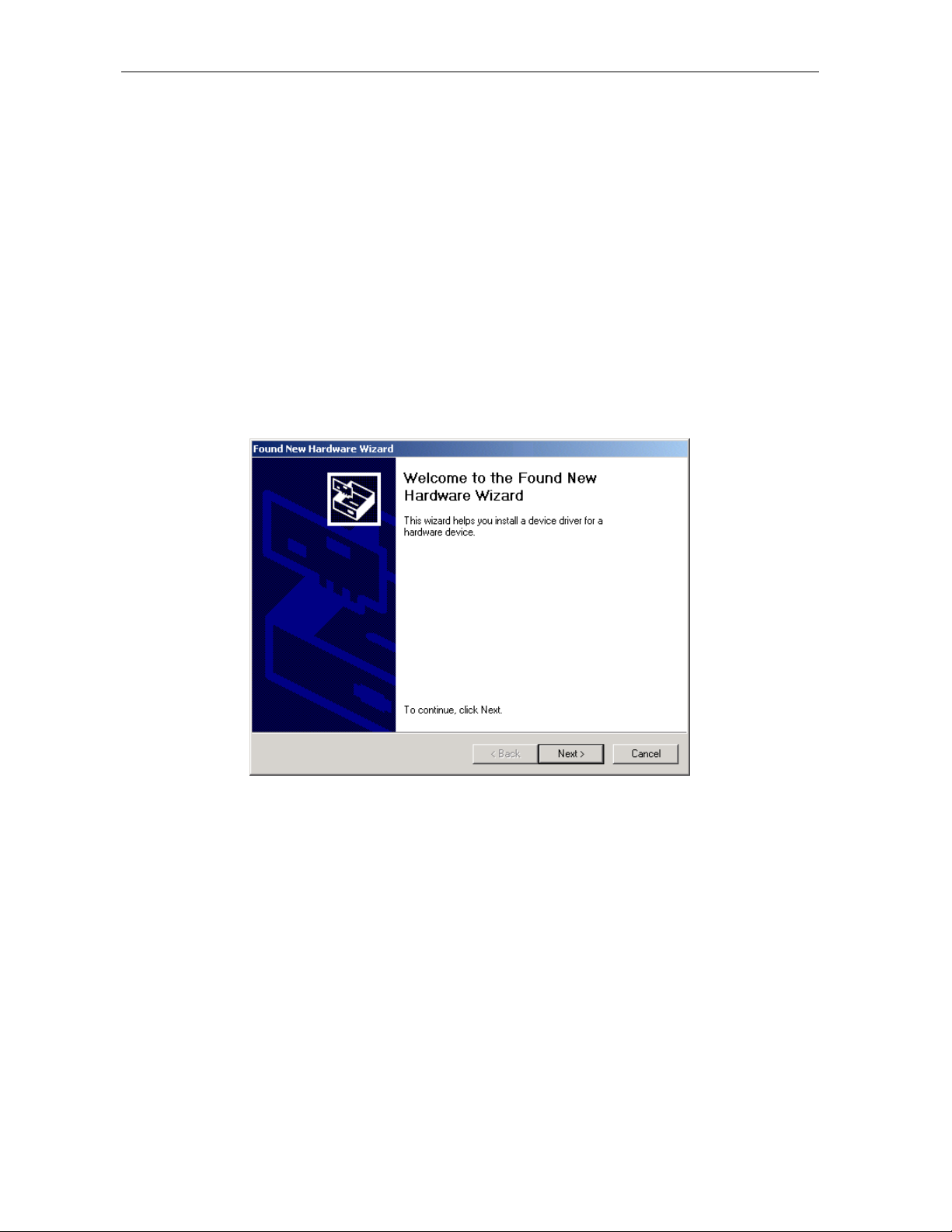
The PC automatically recognizes the USB connection and after several seconds, the
following window is displayed:
Although your SURFboard cable modem model number may be different than in the images
in this manual, the procedure is the same.
SURFboard Cable Modem Installation Manual
Page 25
Installation and Operation 3-11
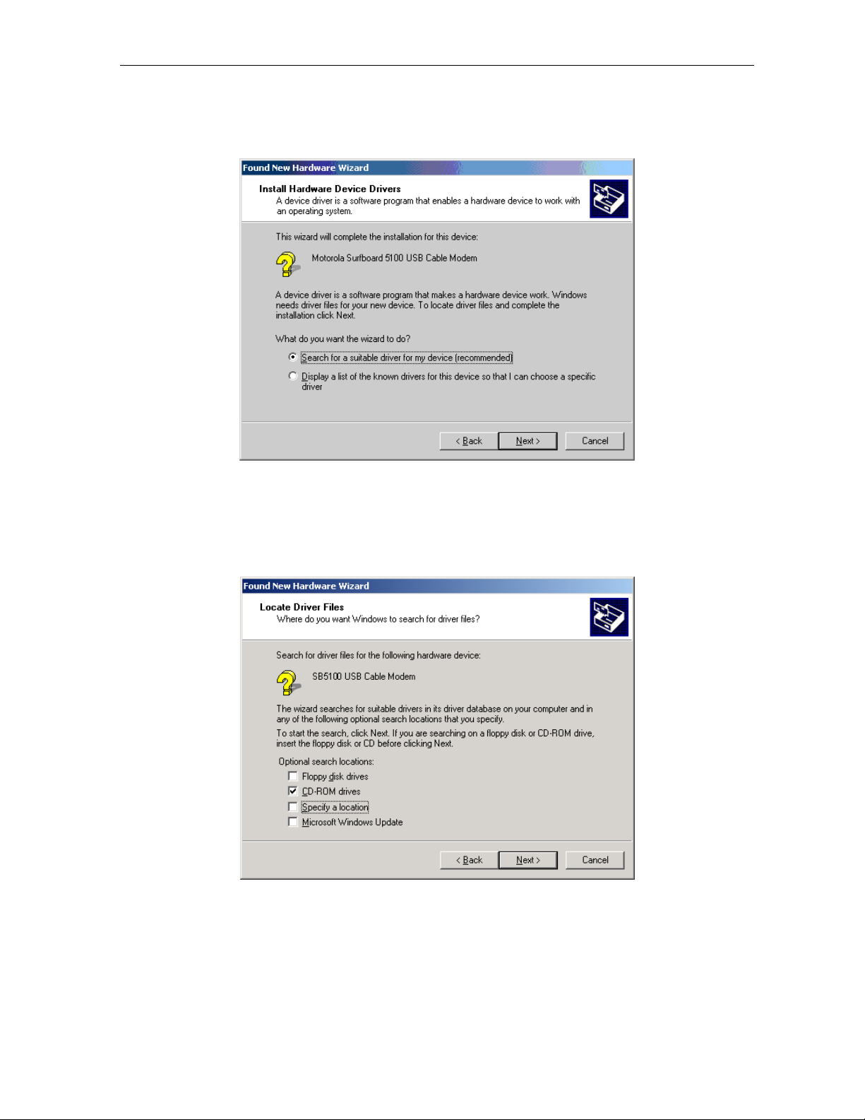
Click Next, and the following window is displayed:
3
Although your SURFboard cable modem model number may be different than in the images
in this manual, the procedure is the same.
4 Ensure that Search for a suitable driver for my device is selected.
5 Click Next and the following window is displayed:
6 Ensure that the box next to the CD-ROM drives is the only one checked as shown in the
window above.
SURFboard Cable Modem Installation Manual
Page 26

3-12 Installation and Operation
Click Next and the window shown below is displayed:
7
Although your SURFboard cable modem model number may be different than in the images
in this manual, the procedure is the same
8
Click Next. If the Insert Disk window is displayed, be sure the SURFboard Cable Modem
.
CD-ROM is in the CD-ROM drive and follow steps 8 to 12. Otherwise, you can skip to
step 12.
9 On the Insert Disk window, click OK. The following window is displayed:
10 If necessary, select your CD-ROM drive in the Copy files from list.
To load the driver successfully, you may need to click Browse to manually select the
NetMotCM.sys file on the CD-ROM.
SURFboard Cable Modem Installation Manual
Page 27
Installation and Operation 3-13
Double-click the NetMotCM.sys file. The Files Needed window is displayed.
11
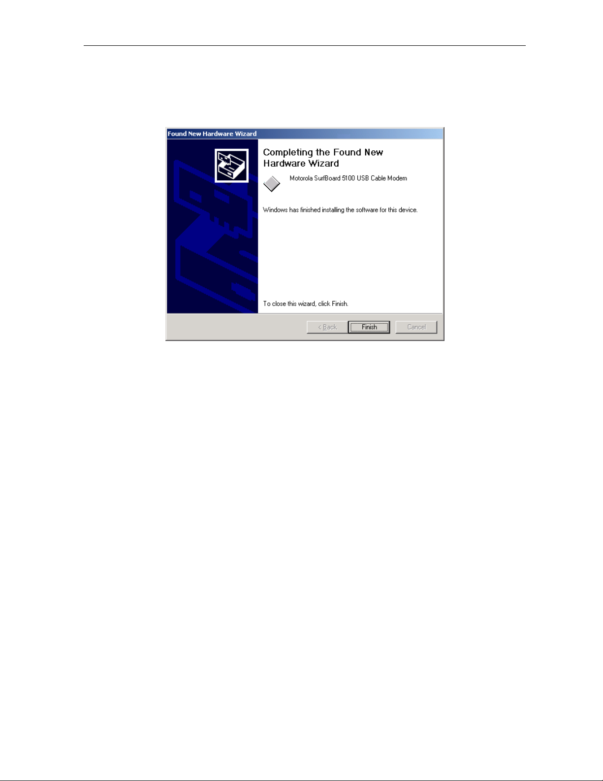
12 Click OK. The Found New Hardware Wizard window is displayed:
13 Click Finish to complete the installation.
When you have successfully finished setting up the USB driver, you can continue with
“Configuring for TCP/IP in Windows 2000,” on page 3-21.
If you have any difficulties setting up the USB driver, follow the instructions for “Removing the
USB Driver from Windows 2000” on page 3-37.
SURFboard Cable Modem Installation Manual
Page 28
3-14 Installation and Operation
Setting Up a USB Driver for Windows Me
To set up a USB driver for Windows Me:
1 Be sure the SURFboard Cable Modem CD-ROM is inserted into the CD-ROM drive before
you plug in the USB cable.
This CD contains the USB drivers and must be inserted and read by the PC before you
connect the cable modem to the PC.
2 Be sure disc load activity is complete before plugging in the USB cable.
System files are needed when loading the USB drivers. These files may already be on the
PC or you may be required to load them from the Microsoft CD that came with the
subscriber’s PC.
The PC automatically recognizes the USB connection and after several seconds, the
following window is displayed:
Although your SURFboard cable modem model number may be different than in the images in
this manual, the procedure is the same.
14 Click Next. Windows Me automatically searches for the correct USB drivers and installs
them.
SURFboard Cable Modem Installation Manual
Page 29
Installation and Operation 3-15
If the window below is displayed, click Finish:
15
Otherwise, ensure that the SURFboard Cable Modem CD-ROM is correctly inserted in your
CD-ROM drive.
When you have successfully finished setting up the USB driver, you can continue with
“Configuring for TCP/IP in Windows 95, Windows 98, and Windows Me,” on page 3-18.
SURFboard Cable Modem Installation Manual
Page 30
3-16 Installation and Operation
Setting Up a USB Driver for Windows XP
To set up a USB driver for Windows XP:
1 Be sure the SURFboard Cable Modem CD-ROM is inserted into the CD-ROM drive before
you plug in the USB cable.
This CD contains the USB drivers and must be inserted and read by the PC before you
connect the cable modem to the PC.
2 Be sure disc load activity is complete before plugging in the USB cable.
System files are needed when loading the USB drivers. These files may already be on the
PC or you may be required to load them from the Microsoft CD that came with the
subscriber’s PC.
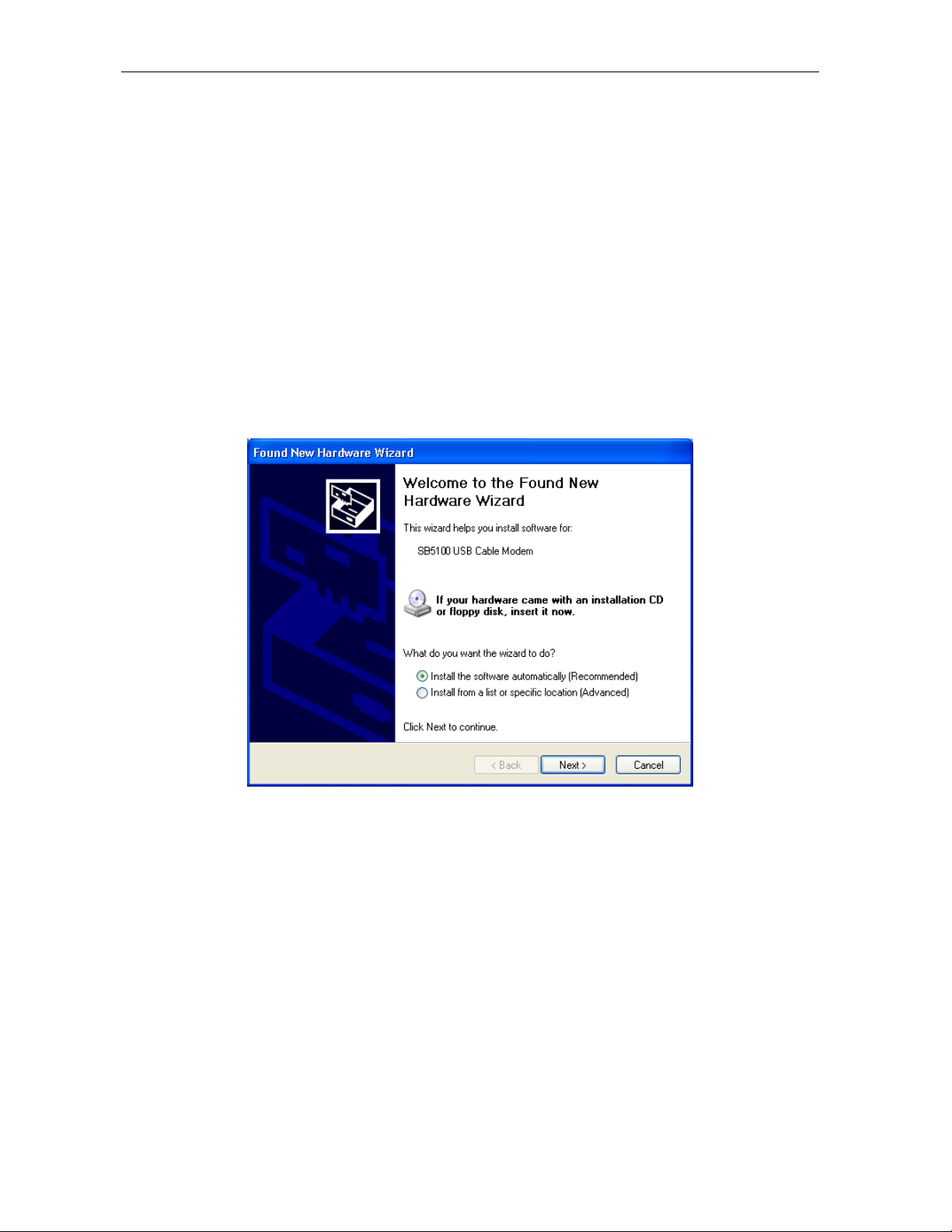
The PC automatically recognizes the USB connection and after several seconds, the
following window is displayed:
Although the SURFboard cable modem model number may be different than in the images in
this manual, the procedure is the same.
3 Ensure that Install the software automatically is selected.
SURFboard Cable Modem Installation Manual
Page 31

Installation and Operation 3-17
Click Next. Windows XP automatically searches for the correct USB drivers and installs
4
them. The following window is displayed:
5 Click Finish to complete the installation.
If you have difficulties setting up the USB driver, follow the instructions for “Removing the
USB Driver from Windows XP on page 3-41.
When you have successfully finished setting up the USB driver, you can continue with
“Configuring for TCP/IP in Windows XP,” on page 3-21.
SURFboard Cable Modem Installation Manual
Page 32

3-18 Installation and Operation
Configuring the Computer for TCP/IP
The computer must be configured for TCP/IP. An IP address is assigned automatically during
the TCP/IP configuration process. Instructions are provided for Windows 95, Windows 98,
Windows Me, Windows 2000, and Window XP users.
The SURFboard cable modem contains all required software. You do not need to configure the
cable modem, but you must configure your computer for TCP/IP (a software protocol for
communication between computers) and check for an IP address. Your service provider may
provide additional instructions for setting up your computer.
Configuring for TCP/IP in Windows 95, Windows 98, and Windows Me
To configure for TCP/IP for Windows 95, Window 98, and Windows Me:
1 On the Windows Desktop, click Start. The pop-up menu is displayed.
2 Click Settings and then Control Panel from the Windows pop-up menus.
3 Double-click the Network icon on the Control Panel window. The Network window is
displayed:
Although your SURFboard cable modem model number may be different than in the images
in this manual, the procedure is the same.
4 Click the Configuration tab on the Network window.
5 Verify that TCP/IP is installed for the adapter that will be used to connect to the
SURFboard cable modem. If TCP/IP is installed, then skip to step 10. If TCP/IP is not
installed for the adapter, continue with step 6.
SURFboard Cable Modem Installation Manual
Page 33

Installation and Operation 3-19
Select the adapter to be used for the SURFboard cable modem connection and then click
6
Add. The Select Network Component Type window is displayed:
7 Double-click the Protocol option. The Select Network Protocol window is displayed:
8 Click Microsoft in the Manufacturers section and then click TCP/IP in the Network
Protocols section.
9 Click OK. The Network window is displayed:
SURFboard Cable Modem Installation Manual
Page 34

3-20 Installation and Operation
Click TCP/IP on the Network window. If there is more than one TCP/IP entry, choose the
10
one for the Ethernet card or USB port connected to the cable modem.
11 Click Properties. The TCP/IP Properties window is displayed:
12 Click the IP Address tab.
13 Click Obtain an IP address automatically.
14 Click OK to accept the TCP/IP settings.
15 Click OK to close the Network window.
16 Click OK when prompted to restart the computer and then click OK again.
When you complete TCP/IP configuration, go to “Verifying an IP Address in Windows 95,
Windows 98, and Windows Me” on page 3-27.
SURFboard Cable Modem Installation Manual
Page 35

Installation and Operation 3-21
Configuring for TCP/IP in Windows 2000
To configure for TCP/IP for Windows 2000:
1 On the Windows Desktop, click Start.
2 Click Settings and then Control Panel from the pop-up menus:
3 Double-click the Network and Dial-up Connections icon on the Control Panel window to
display the window shown below:
4 On the Network and Dial-up Connections window, double-click Local Area Connection
number. The value of this number varies from system to system.
SURFboard Cable Modem Installation Manual
Page 36

3-22 Installation and Operation
The Local Area Connection number Status window is displayed:
5 Click Properties. A window similar to the following is displayed:
6 If Internet Protocol (TCP/IP) is displayed in the list of network components, TCP/IP is
installed. You can skip to step 10.
SURFboard Cable Modem Installation Manual
Page 37

Installation and Operation 3-23
If Internet Protocol (TCP/IP) is not in the list, click Install. The Select Network Component
Type window is displayed:
7 Click Protocol on the Select Network Component Type window and then click ADD. The
Select Network Protocol window is displayed similar to the one shown below:
8 Click Internet Protocol (TCP/IP) in the Network Protocol section of Select Network Protocol
window.
9 Click OK.
SURFboard Cable Modem Installation Manual
Page 38

3-24 Installation and Operation
The Local Area Connection number Properties window is re-displayed:
10 On the Local Area Connection number Properties window, ensure that the box next to
Internet Protocol (TCP/IP) is checked.
11 Click Properties. The Internet Protocol (TCP/IP) Properties window is displayed:
12 Ensure that Obtain IP address automatically and Obtain DNS server address
automatically are selected.
SURFboard Cable Modem Installation Manual
Page 39

Installation and Operation 3-25
Click OK to accept the TCP/IP settings.
13
14 Click OK to close the Local Area Connection number Properties window.
15 Click OK when prompted to restart the computer and then click OK again.
When you complete the TCP/IP configuration, go to “Verifying an IP Address in Windows 2000
or Windows XP” on page 3-29.
Configuring for TCP/IP in Windows XP
To configure for TCP/IP for Windows XP:
1 On the Windows Desktop, click Start to display the Start window:
2 Click Control Panel to display the Control Panel widow. The display varies, depending on
your Windows XP view options. If the display is a Category view as shown in the following
illustration, continue to step 3. Otherwise, skip to step 5.
3 Click Network and Internet Connections to display the Network and Internet
Connections window.
4 On the Network and Internet Connections Pick a task window, click Network
Connections to display the LAN or High-speed Internet connections. Skip to step 6.
SURFboard Cable Modem Installation Manual
Page 40

3-26 Installation and Operation
If a classic view similar to the illustration below is displayed, click Network Connections
5
to display the LAN or High-speed Internet connections.
6 Right-click on your network connection. If more than one connection is displayed, be sure to
select the one for your network interface.
7 Select Properties from the pop-up menu to display the Local Area Connection Properties
window:
8 On the Local Area Connection Properties window, be sure Internet Protocol (TCP/IP) is
checked. If it is not checked, check it.
9 Select Internet Protocol (TCP/IP) and click Properties to display the Internet Protocol
(TCP/IP) Properties window:
SURFboard Cable Modem Installation Manual
Page 41

Installation and Operation 3-27
Verify that the settings are correct, as shown in the illustration below:
10
11 Click OK to close the TCP/IP Properties window.
12 Click OK to close the Local Area Connection Properties window.
When you complete the TCP/IP configuration, go to “Verifying an IP Address in Windows 2000
and Windows XP on page 3-29
Verifying an IP Address
The following sections describe how to verify an IP address. Instructions are provided for
Windows 95, Windows 98, Windows Me, Windows 2000, and Windows XP users.
Verifying an IP Address in Windows 95, Windows 98, and Windows Me
To check the IP address on a computer running Windows 95, Windows 98 or Windows Me:
1 On the Windows Desktop, click Start. The pop-up menu is displayed.
2 Click Run, and the Run dialog box is displayed:
SURFboard Cable Modem Installation Manual
Page 42

3-28 Installation and Operation
Type winipcfg.exe and then click OK. The IP Configuration window is displayed:
3
In Windows 98, IP Autoconfiguration should not be shown before IP address or an error
condition exists. An example is shown below.
The values shown for Adapter Address, IP Address, Subnet Mask, and Default Gateway on your PC will be different from those
shown in the examples.
If an IP address is not displayed or has all zeros in Windows 95, an error condition exists.
If Autoconfiguration is displayed before IP Address in Windows 98, an error condition exists.
4
Select the adapter — the Ethernet card or USB device.
5 Click Renew.
6 After the system displays an IP address, click OK.
SURFboard Cable Modem Installation Manual
Page 43

Installation and Operation 3-29
Verifying an IP Address in Windows 2000 and Windows XP
To check the IP address on a computer running Windows 2000 or Windows XP:
1
On the Windows Desktop, click Start.
2 Click Run. The Run window is displayed:
3 Type cmd and click OK. A DOS window is displayed:
4 Type ipconfig and press ENTER to display the computer’s IP configuration:
SURFboard Cable Modem Installation Manual
Page 44

3-30 Installation and Operation
Type exit and press ENTER to return to the Windows operating system.
5
Improper connections between the subscriber’s PC, the SURFboard cable modem, and the
cable network are indicated when you receive an Autoconfiguration IP Address. An example
is displayed below. Check the subscriber’s cabling and determine if you can see the regular
cable-TV channels on the subscriber’s television.
After verifying the subscriber’s cable connections and proper operation of the cable-TV system
by looking at the channels on the TV, you can renew the IP address.
SURFboard Cable Modem Installation Manual
Page 45

Installation and Operation 3-31
Renewing an IP Address
To renew an IP address:
1 Type ipconfig /renew and then press ENTER. If a valid IP address is displayed, then Internet
access should be available.
2 Type exit and then press ENTER to return to Windows.
Installing Multiple Users
The SURFboard cable modem can serve as a gateway to the Internet for up to 32 users when
using an optional hub or switch. The users must be on the LAN and the SURFboard cable
modem must be attached to the LAN and the cable system.
The following three diagrams illustrate sample configurations. Figure 3-2 illustrates the basic
connections with one interface:
Figure 3-2
Ethernet - Multiple users
Cable outlet
Coaxial cable
SURFboard
cable modem
Ethernet crossover cable
Ethernet hub
or switch
Ethernet cable
Computer Computer
Computer
SURFboard Cable Modem Installation Manual
Page 46

3-32 Installation and Operation
Figure 3-3 illustrates connecting one computer to the USB port and a second computer to the
Ethernet port:
Figure 3-3
Ethernet - Two users with two interfaces
Cable outlet
Coaxial cable
SURFboard
cable modem
USB cable
Computer
Ethernet crossover cable
Computer
You can use the Ethernet and USB interfaces to connect multiple users. Connect a single user to
the USB port and up to 31 users to the Ethernet hub or switch. Figure 3-4 illustrates both
interfaces:
Figure 3-4
Ethernet - Multiple users with two interfaces
Cable outlet
Coaxial cable
SURFboard
cable modem
USB cable
Computer
Ethernet cable
Ethernet crossover cable
Ethernet hub
or switch
Computer Computer
Computer
SURFboard Cable Modem Installation Manual
Page 47

Installation and Operation 3-33
Removing the USB Driver
The following sections describe how to remove the device listings from the SURFboard cable
modem. Instructions are provided for Windows 98, Windows Me, Windows 2000, and
Windows XP users.
Removing the USB Driver from Windows 98 or Windows Me
To remove the USB driver from Windows 98 or Windows Me:
1 Ensure that the USB cable is removed from your PC or cable modem.
The USB cable must be unplugged prior to restarting or the PC will re-detect the modem and
reinstall the USB driver.
2 On the Windows Desktop, right-click the Network Neighborhood icon for Windows 98 or
My Network Places for Windows Me and then click Properties. The Network window is
displayed:
SURFboard Cable Modem Installation Manual
Page 48

3-34 Installation and Operation
Select Motorola SurfBoard USB Cable Modem (although your SurfBoard cable modem
3
model number may be different than the images in this guide, the procedure is the same):
4 Click Remove. The Network window no longer shows the Motorola SURFboard USB Cable
Modem in the list:
SURFboard Cable Modem Installation Manual
Page 49

Installation and Operation 3-35
Click OK, and the System Settings Change window is displayed:
5
6 Click Yes to restart your computer.
7 Insert the SURFboard Cable Modem CD-ROM in the CD-ROM drive. After a short time, a
window with language choices is displayed.
8 Press the Esc key on the keyboard to exit the start-up screens.
9 To start Windows Explorer, click Start and select Run.
10 In the Run window, type explorer and click OK. The Explorer window is displayed.
11 Double-click the CD-ROM drive icon (drive D: in our example).
12 Double-click the remove.exe icon to run the Remove utility from the SURFboard Cable
Modem CD-ROM.
SURFboard Cable Modem Installation Manual
Page 50

3-36 Installation and Operation
The SURFboard Cable Modem USB Driver Removal window is displayed:
13 Click Remove Driver to remove the USB driver.
After you remove the USB driver, re-install the USB driver following either:
“Setting Up a USB Driver for Windows 98,” on page 3-5.
“Setting Up a USB Driver for Windows Me,” on page 3-14
SURFboard Cable Modem Installation Manual
Page 51

Installation and Operation 3-37
Removing the USB Driver from Windows 2000
To remove the USB driver from Windows 2000:
1 From the Windows 2000 desktop, click Start.
2 Click Settings:
3 Click the Control Panel icon and the Control Panel window is displayed:
SURFboard Cable Modem Installation Manual
Page 52

3-38 Installation and Operation
Double-click System and the System Properties window is displayed:
4
5 Click the Hardware tab then click on Device Manager to display the Device Manager
window.
6 Double-click Network Adapters:
SURFboard Cable Modem Installation Manual
Page 53

Installation and Operation 3-39
Click Motorola Surfboard USB Cable Modem. The Uninstall icon is displayed on the
7
window near the top:
8 Click the Uninstall icon
9 Close the Device Manager window.
10 Close the Control Panel window.
11 Insert the SURFboard Cable Modem CD-ROM in the CD-ROM drive. After a short time, a
window with language choices is displayed.
12 Press the Esc key on the keyboard to exit the start-up screens.
13 To start Windows Explorer, click Start and select Run.
14 In the Run window, type Explorer and click OK.
15 Double-click My Computer.
SURFboard Cable Modem Installation Manual
Page 54

3-40 Installation and Operation
Double-click the CD-ROM drive icon (drive D: in our example).
16
17 Double-click the remove.exe icon. The SURFboard Cable Modem USB Driver Removal
window is displayed:
The USB cable must be disconnected before running the REMOVE utility.
SURFboard Cable Modem Installation Manual
Page 55

Installation and Operation 3-41
Click Remove Driver.
18
Informational messages similar to the ones shown in the window above are displayed on the
SURFboard Cable Modem USB Driver Removal window.
After you remove the USB driver, re-install the USB driver from “Setting Up a USB Driver for
Windows 2000,” on page 3-10.
Removing USB Driver from Windows XP
To remove USB driver from Windows XP:
1 Click Start to display the Windows XP Start window:
SURFboard Cable Modem Installation Manual
Page 56

3-42 Installation and Operation
Click Control Panel to display the Control Panel window (the display varies, depending on
2
your Windows XP view options).
3 If a Category view similar to the one illustrated above is displayed, click Performance and
Maintenance. The Performance and Maintenance window is displayed:
4 Click System to display the System Properties window.
SURFboard Cable Modem Installation Manual
Page 57

Installation and Operation 3-43
If a classic view is displayed, click System to display the System Properties window:
5
6 Click the Hardware tab.
7 Double-click the Device Manager button to display the Device Manager window:
SURFboard Cable Modem Installation Manual
Page 58

3-44 Installation and Operation
Double-click Network adapters. The adapters are displayed:
8
9 Click Motorola Surfboard USB Cable Modem. The Uninstall icon is displayed on the
window near the top:
SURFboard Cable Modem Installation Manual
Page 59

Installation and Operation 3-45
Click the Uninstall icon.
10
11 Close the Device Manager window.
12 Close the Control Panel window.
13 Insert the SURFboard Cable Modem CD-ROM in the CD-ROM drive. After a short time, a
window with language choices is displayed.
14 Press ESC to exit the start-up screens.
15 To start Windows Explorer, click Start and select Run.
16 In the Run window, type explorer and click OK.
17 Double-click My Computer.
18 Double-click the CD-ROM drive icon (drive D: in our example).
SURFboard Cable Modem Installation Manual
Page 60

3-46 Installation and Operation
Double-click the remove.exe icon. The SURFboard Cable Modem USB Driver Removal
19
window is displayed:
The USB cable must be disconnected before running the REMOVE utility.
20 Click Remove Driver.
Informational messages similar to the ones shown in the window above are displayed on the
SURFboard Cable Modem USB Driver Removal window.
After you remove the USB driver, re-install the USB driver from “Setting Up a USB Driver for
Windows XP,” on page 3-16.
Recovering from Windows 98 or Win98_SE Installation Errors
This section discusses recovering from installation errors using the Motorola Remove program
or Solution procedures.
If you cannot successfully install the USB driver or an error is displayed during driver
installation, there may be invalid entries in the Windows Device Manager. Depending on where
the error occurred, run the Motorola Remove program or perform the Solution procedures.
Remove Program
The Motorola Remove program deletes improper Windows entries that may have occurred
during installation. It performs the same function as the device removals in Solutions 1 and 2.
The Remove program and the latest drivers can be downloaded from the website
ftp://ftp.surfboard.com/
pub/Downloads/SURFboard_USB_Driver/v20_Drivers.exe.
. The files are in the following directory path:
Before running the Remove program, unplug the USB cable from the cable modem.
SURFboard Cable Modem Installation Manual
Page 61

Installation and Operation 3-47
Solutions
If you choose not to run the Motorola Remove program, you can perform the procedures in
Solution 1 or Solution 2. Review both solutions before choosing which one to run.
Solution 1
1 Leave the USB cable plugged into the SURFboard cable modem and the computer.
2 From the Windows Desktop, right-click the My Computer icon to display a list of options.
3 Click Properties at the bottom of the list. The System Properties window is displayed.
4 On the System Properties window, click the Device Manager tab.
5 Expand the Universal Serial Bus controllers branch and see if there is an entry for USB
Composite Device. The following additional entries are automatically removed when the
USB Composite Device is removed:
# Windows 98 Second Edition may list two entries as USB Cable Modem under Other
Devices.
# Windows 98 may list two entries as Unknown Devices under Other Devices.
These additional entries are automatically removed when the USB Composite Device is
removed.
6 Select the USB Composite Device and click Remove.
CAUTION!
Extremely Important: After removing the USB composite device, disconnect the USB cable from the SURFboard
cable modem and reboot the PC. To reinstall the USB drivers, follow the instructions in “Setting Up a USB Driver
for Windows 98”, page 3-5
SURFboard Cable Modem Installation Manual
Page 62

3-48 Installation and Operation
Solution 2
The USB drivers may have loaded, but a protocol was not bound to the adapter. To test this:
1 Remove the USB cable from the SURFboard cable modem.
2 From the Windows Desktop, right-click the Network Neighborhood icon to display a list of
options.
3 Click Properties at the bottom of the list. The Network window is displayed:
4 Click the Configuration tab, select the Motorola Surfboard USB Cable Modem entry, and
then click Properties.
5 Click the Bindings tab. If TCP/IP is not listed, either add the protocol to the adapter or
remove the entry for Motorola SURFboard USB Cable Modem.
6 To remove the entry, in the Network window, select Motorola SURFboard USB Cable
Modem and click Remove.
CAUTION!
Extremely Important: After removing the device, restart the computer. To reinstall the USB drivers, follow the
instructions in “Setting Up a USB Driver for Windows 98”, page 3-5
The Motorola Remove program deletes improper Windows 98, Windows 98 Second Edition,
Windows Me, Windows 2000, and Windows XP entries that may have occurred in the installation
process.
The Remove program and the latest drivers are available for download from the website
ftp://ftp.surfboard.com/
. The files are in the following directory path:
pub/Downloads/SURFboard_USB_Driver/v20_Drivers.exe.
SURFboard Cable Modem Installation Manual
Page 63

Installation and Operation 3-49
Prior to running the Remove program, unplug the USB cable from the SURFboard cable
modem. The Remove program performs the same function as the removal of devices performed
in Solution 1 and Solution 2 on the previous pages.
Setting the Frequency Using StormWatch
StormWatch™, the SURFboard Cable Modem Diagnostic Suite, is a cable modem utility that is
available from Motorola. It runs from a CD-ROM and does not require installation on a hard
drive. It can be used when installing the SURFboard cable modem to set the frequency and save
startup time.
To set the frequency:
1 For the SURFboard cable modem, ensure that a laptop or PC is connected to the SURFboard
cable modem rear-panel Ethernet port.
2 Turn on the PC and ensure that the SURFboard cable modem is booted up.
3 Connect StormWatch to 192.168.100.1.
4 Click Configure and then click Channel Parameter.
5 Type the desired frequency in Hertz; for example, 411 MHz = 411000000, in the
Downstream Frequency field.
6 Type the upstream channel ID in the Upstream Channel ID field. (Not required)
7 Select a frequency plan type in the Frequency Plan field.
8 Click Save and then restart the cable modem.
SURFboard Cable Modem Installation Manual
Page 64

Section 4
HTML User Interface
This section provides instructions for using the SURFboard cable modem HTML user interface.
The windows — Help, Startup, Signal, Addresses, Configuration, and Logs — provide
configuration and troubleshooting information, such as MAC and IP addresses and frequency
and Event logs.
The IP address for this user interface is 192.168.100.1. To use the HTML user interface:
1 Connect a cable from the laptop or PC Ethernet port to the cable modem Ethernet port on
the SURFboard cable modem rear panel.
2 Turn on the PC and verify that the SURFboard cable modem is plugged in.
3 Open the browser.
4 Type http://192.168.100.1/mainhelp.html. A Configuration Manager Help window is
displayed as illustrated in Figure 4-1:
Figure 4-1
Configuration Manager Help window
This window provides an overview of the other windows and a standard troubleshooting
checklist. From this window you can select any of the other windows by clicking on the
buttons on the bottom toolbar.
SURFboard Cable Modem Installation Manual
Page 65

4-2 HTML User Interface
Click Status, and the Configuration Manager Startup window is displayed:
5
Figure 4-2
Configuration Manager Startup window
This window provides a power-up status for each item on the Task list. The last Status
entry should be Operational as illustrated in Figure 4-2.
SURFboard Cable Modem Installation Manual
Page 66

HTML User Interface 4-3
Click Signal to display the Configuration Manager Signal window:
6
Figure 4-3
Configuration Manager Signal window
This window provides the current downstream and upstream information.
SURFboard Cable Modem Installation Manual
Page 67

4-4 HTML User Interface
Click Addresses to display the Configuration Manager Addresses window:
7
Figure 4-4
Configuration Manager Addresses window
This window provides a serial number, a list of current addresses, and DHCP information.
SURFboard Cable Modem Installation Manual
Page 68

HTML User Interface 4-5
Click Configuration to display the Configuration Manager Configuration window:
8
Figure 4-5
Configuration window
The Configuration window displays the Frequency Plan, Upstream Channel ID, and Frequency
that the cable modem currently uses for communication.
SURFboard Cable Modem Installation Manual
Page 69

4-6 HTML User Interface
Type http://192.168.100.1/logs.html, and the Configuration Manager Logs window is
9
displayed:
Figure 4-6
Configuration Manager Logs window
This is a sample Events Log that is generated during startup and during operation. Refer to
Appendix B, “Event Log Messages,” for the format and code definitions.
SURFboard Cable Modem Installation Manual
Page 70

Section 5
Troubleshooting
This section provides information to assist you in quickly detecting, isolating, and resolving
error conditions that might occur when using the SURFboard cable modem.
If you are still having trouble after trying the solutions found in this section, contact the
Motorola Technical Response Center (TRC) at 1-888-944-HELP. Fill out the Troubleshooting
Checklist (Table 5-2) before calling TRC.
If the SURFboard cable modem was off, it may require up to 10 minutes to scan for the
upstream and downstream channels again. Table 5-1 lists fault indications, their symptoms,
and possible resolutions:
Table 5-1
Troubleshooting guidelines
Problem Possible Solution
Green POWER LED is off
Cannot receive or send
data
Receive
Send
Online
Power The modem may be in standby mode, press the Standby
Check that the power cord is properly plugged into the outlet and SURFboard
cable modem.
Check that the electrical outlet is working.
Press the Standby button to reconnect to the Internet service.
Press the Reset button.
Check the LEDs. From top to bottom, note the first LED that is off. This LED
indicates where the error occurred. If the first LED that is off is:
During startup, the downstream receive channel is not acquired.
During normal operation, the downstream receive channel is
lost.
During startup, the upstream transmit channel is not acquired.
During normal operation, the upstream transmit channel is lost.
During startup, the IP registration was not successful.
During normal operation, the IP registration is lost.
button.
Verify that the TV is working and has a clear picture.
Check the coaxial cable at the modem and outlet and hand-tighten if
necessary.
Check the IP address (follow the steps in Section 3, “Installation and
Operation”).
SURFboard cable modem Installation Manual
Page 71

5-2 Troubleshooting
Table 5-2 is the troubleshooting checklist that provides TRC with needed information:
Table 5-2
Troubleshooting checklist
Complete description of the problem
Network layout and IP addresses
Firmware version *
CMTS:
Type
Operating system version
DHCP:
Operating system
Software version
Copy of the Event Log *
Copy of cable modem TFTP configuration
file
Where in boot sequence does the
SURFboard cable modem:
! fail
! monitor the LEDs
! monitor the console cable output if active
Does it acquire a downstream frequency
lock?
Does it acquire an upstream channel?
Does it complete DHCP registration?
Does it get a successful TFTP download?
Did it work at one time, and if so, what has
changed?
Does this issue affect other DOCSIS
vendor modems?
Does this issue affect all nodes in the
cable system?
Does the SURFboard cable modem work if
provisioned in the headend, for example
system test point or right at the node?
What application, if any, is failing and in
what way?
If multi-user, is the MAX-CPE turned on in
the DOCSIS TFTP configuration file?
* The firmware version and Event Log are accessible using the StormWatch Diagnostic Suite.
SURFboard cable modem Installation Manual
Page 72

Appendix A
Specifications
Downstream
Modulation
Data rate
Frequency
Bandwidth
Symbol rate:
64 QAM
256 QAM
Operating level
Input impedance
Upstream
Modulation
Transmission rate
Bandwidth
Frequency
Symbol rates
Operating levels:
16 QAM
QPSK
Output impedance
64 QAM or 256 QAM
38 Mbps maximum (limited by such factors as customer provider
equipment (CPE) and service provider restrictions)
88 MHz to 860 MHz (30 kHz minimum step size)
6 MHz
5.069 Msym/s maximum
5.361 Msym/s maximum
-15 dBmV to +15 dBmV
75 ohms nominal
16 QAM or QPSK (variable symbol rates)
30 Mbps maximum
200 kHz to 3200 kHz
5 MHz to 42 MHz (edge to edge)
160, 320, 640, 1280, and 2560 ksym/s
+8 dBmV to +55 dBmV
+8 dBmV to +53 dBmV
75 ohms nominal
General
Data protocol
Interface to PC
Power
Power adapter input
Dimensions
Operating temperature
Storage temperature
Operating humidity
SURFboard Cable Modem Installation Manual
TCP/IP
Ethernet 10/100Base-T and USB
Approximately 9 Watts (+12VDC)
North America:
105 to 125 Vac, 60 Hz
International:
100 to 240 Vac, 50 to 60 Hz
6.2” H x 2.3” W x 6.0” L
0 to +40º C
-30º C to +80º C
0% to 95% RH, non-condensing
Page 73

Appendix B
Event Log Messages
This appendix defines the messages in the Events Log. This log is generated during startup and
operation and contains up to 200 entries.
Event Message Format
The entries can be 80 characters long and contain a time stamp, the priority level, and a letter
and numeric code.
The format is MMDDHHMMSS P XNNN.N event message.
MMDDHHMMSS
P
X
NNN.N
Event message
Time stamp consisting of 10 characters. ********** is displayed until the time is
retrieved from the timeserver
Log priority level (refer to Table B-1)
Letter code associated with the message
Numeric code associated with the message
String reporting status or error (can contain specific values which apply to the
event being reported)
Priority Levels
Table B-1 describes the priority level:
Table B-1
Priority level
Priority
Level
1 Emergency
2 Alert
3 Critical
4 Error
5 Warning
6 Notice
7 Information
8 Debug
Description Log Priority Level
A panic condition that is broadcasted to all users.
A condition to be corrected immediately, such as a corrupted system database.
A critical condition such as hard device errors.
Error messages.
Warning messages.
Conditions that are not error conditions but may require special handling.
Informative messages.
Messages that contain information normally used to debug a program.
SURFboard Cable Modem Installation Manual
Page 74

B-2 Event Log Messages
Predefined Log Messages
SP-RFI_I05-991105 – Error Codes for MAC Management Messages
SYNC Timing Synchronization
Code Event Log Messages Level Cable Modem Actions
T00.0
T01.0
T02.0
T02.1
T03.0
T04.0
T05.0
SYNC Timing Synchronization
Failed to acquire QAM/QPSK symbol
timing. Error stats? Retry #s?
Failed to acquire FEC framing. Error
stats? Retry #s? # of bad frames?
Acquired FEC framing. Failed to aquifer
MPEG2 Sync. Retry #s?
Failed to acquire MAC framing. Error
stats? Retry #s? # of bad frames?
Failed to Receive MAC SYNC frame
within time-out period.
Loss of Sync. (Missed 5 in a row, after
having Synced at one time)
UCD Upstream Channel Descriptor
Code Event Log Messages Level Cable Modem Actions
U00.0
U01.0
U02.0
U03.0
U04.0
U05.0
U06.0
UCD Upstream Channel Descriptor
No UCDs Received. Time-out.
UCD invalid or channel unusable.
UCD valid, BUT no SYNC received.
TIMED OUT.
UCD & SYNC valid, NO MAPS for THIS
Channel.
UCD received with invalid or out of order
Configuration Change Count.
US Channel wide parameters not set
before Burst Descriptors
MAP Upstream Bandwidth Allocation
Code Event Log Messages Level Cable Modem Actions
M00.0
M01.0
SURFboard Cable Modem Installation Manual
MAP Upstream Bandwidth Allocation
A transmit opportunity was missed
because the MAP arrived too late
Page 75

Event Log Messages B-3
RNG-RSP Ranging Response
Code Event Log Messages Level Cable Modem Actions
R00.0
R01.0
R02.0
R03.0
R04.0
R05.0
R06.0
R07.0
RNG-RSP Ranging Response
NO Maintenance Broadcasts for Ranging
opportunities Received T2 time-out.
No Ranging Response received, T3 timeout
Ranging Request Retries exhausted.
Received Response to Broadcast
Maintenance Request, But no Unicast
Maintenance opportunities received. T4
time-out.
Started Unicast Maintenance Ranging no
Response received. T3 time-out.
Unicast Maintenance Ranging attempted,
No Response, Retries exhausted.
Unicast Ranging Received Abort
Response, Re-initializing MAC.
RNG-REQ Ranging Request
Code Event Log Messages Level Cable Modem Actions
R100.0
R101.0
R102.0
R103.0
R104.0
RNG-REQ Ranging Request
No Ranging Requests received from
POLLED CM (CMTS generated polls)
Retries exhausted for polled CM (report
SID). After 16 R101.0 errors.
Unable to Successfully Range CM (report
SID) Retries Exhausted. Note: this is
different from R102.0 in that it was able to
try; i.e., got REQs but failed to Range
properly.
Failed to receive Periodic RNG-REQ from
modem (SID X), Timing-out SID.
REG-REQ Registration Request
Code Event Log Messages Level Cable Modem Actions
I100.0
I101.0
REG-REQ Registration Request 7 (Info) No action taken
Invalid MAC header.
I102.0
SURFboard Cable Modem Installation Manual
Invalid SID, not in use.
Page 76

B-4 Event Log Messages
Code Event Log Messages Level Cable Modem Actions
I103.0
I104.0
I105.0
I105.1
I105.2
I106.0
I106.1
I107.0
I108.0
I109.0
I110.0
I111.0
I111.1
I112.0
I112.1
I113.0
I113.1
I114.0
I114.1
I114.2
I114.3
I114.4
I115.0
Required TLVs out of order.
Required TLVs not present.
Down Stream Frequency format invalid in
length.
Down Stream Frequency not in use.
Down Stream Frequency invalid, not a
multiple of 62500Hz.
Up Stream Channel invalid, unassigned. 4 (Error)
Up Stream Channel Change followed with
(RE-) Registration REQ.
Up Stream Channel overloaded.
Network Access configuration has invalid
parameter (length).
Class of Service configuration is invalid.
Class of Service ID is not in TFTP config. 7 (Info) No action taken
Class of Service ID out of range. 4 (Error) Continue reading next bytes of Config
Class of Service ID invalid length 4 (Error)
Max Downstream Bit rate configuration
has invalid length
Max Downstream Bit Rate configuration is
not in TFTP config.
Max Upstream Bit rate configuration has
invalid length
Max Upstream Bit Rate configuration is
not in TFTP config
Up Stream Priority configuration invalid
format.
Up Stream Priority configuration setting
out of range.
Upstream Priority configuration has invalid
length
Vendor Spec has invalid length/type of
vendor ID
Vendor Spec has invalid length 4 (Error) Set to correct length and continue
Min Upstream Channel Bit Rate
configuration setting invalid length
4 (Error) Won’t be saved to memory
4 (Error) CM will continue reading next bytes of
Config file.
Set to 0 value
4 (Error) Continue reading next bytes of Config
file. Set to 0 value
file. Log it. If Reg-Response returns OK,
reboot to notify CMTS the range error
4 (Error) Continue reading next bytes of Config
file. Set to 0 value
7 (Info) Continue reading next bytes of Config
file. Set to 0 value
4 (Error) Continue reading next bytes of Config
file. Set to 0 value
7 (Info) Continue reading next bytes of Config
file.
4 (Error)
4 (Error) Continue reading next bytes of Config
file.
Set to 7 value as lowest priority
4 (Error) Set to correct length and continue
reading next bytes of Config file.
4 (Error) Set to correct length and continue
reading next bytes of Config file.
reading next bytes of Config file.
4 (Error) Continue reading next bytes of Config
file. Set to 0 value
SURFboard Cable Modem Installation Manual
Page 77

Event Log Messages B-5
Code Event Log Messages Level Cable Modem Actions
I115.1
I115.2
I116.0
I116.1
I117.0
I117.1
Guaranteed Min Up Stream Channel Bit
Rate configuration setting exceeds Max
Upstream Bit Rate.
Guaranteed Min Up Stream Channel Bit
Rate configuration setting out of range
Max Upstream Channel Transmit Burst
configuration setting invalid length
Max Up Stream Channel Transmit Burst
configuration setting out of range
Modem Capabilities configuration setting
invalid format.
Modem Capabilities configuration setting. 7 (Info) No action taken
4 (Error) Continue reading next bytes of Config
file. Set to Max
4 (Error) Continue reading next bytes of Config
file. Set to 0 value
4 (Error) Continue reading next bytes of Config
file. Set to 255
7 (Info) Continue reading next bytes of Config
file. Set to 0 value
REG-RSP Registration Response
Code Event Log Messages Level Cable Modem Actions
I00.0
I01.0
I02.0
I03.0
I04.0
I04.1
I04.2
I04.3
REG-RSP Registration Response 7 (Info) No action taken
Registration RSP invalid format or not
recognized
Registration RSP not received. 4 (Error) Reset the board.
Registration RSP with bad SID. 4 (Error) Continue reading next bytes of REG-
Service not available. Reason: Other
Service not available. Reason:
Unrecognized configuration setting
Service not available. Reason:
Temporarily unavailable
Service not available. Reason: Permanent
4 (Error) Ignore it and continue reading next
bytes of REG-RSP msg
RSP msg.
UCC-REQ Upstream Channel Change Request
Code Event Log Messages Level Cable Modem Actions
C00.0
C01.0
C02.0
SURFboard Cable Modem Installation Manual
UCC-REQ Upstream Channel Change
Request
Async Msg received with invalid US
Channel ID length.
UCC-REQ received unable to send UCCRSP, no TX opportunity.
7 (Info) No action taken
4 (Error) CM will fix to correct length, continue
parsing the channel ID value, and send
UCC-RSP to CMTS.
Page 78

B-6 Event Log Messages
UCC-RSP Upstream Channel Change Response
Code Event Log Messages Level Cable Modem Actions
C100.0
C101.0
C102.0
C103.0
UCC-RSP Upstream Channel Change
Response
UCC-RSP not received on previous
channel ID.
UCC-RSP received with invalid channel
ID.
UCC-RSP received with invalid channel
ID on new channel.
7 (Info) No action taken
DHCP CM Net Configuration Download and Time of Day
Code Event Log Messages Level Cable Modem Actions
D00.0
D01.0
D02.0
D03.0
D03.1
D04.0
D04.1
D04.2
D05.0
D06.0
D07.0
DHCP CM Net Configuration download
7 (Info) No action taken
and Time of Day
Discover sent no Offer received, No
4 (Error)
available DHCP Server.
Request sent, no Response. 4 (Error)
Requested Info not supported. 4 (Error)
DHCP response doesn't contain ALL the
4 (Error)
valid fields as described in the RF spec
Time of Day, none set or invalid data.
Time of Day Request sent no Response
5 (Warn) CM will time out in 10 secs and retry 2
received
Time of Day Response received but
5 (Warn) CM will time out in 10 secs and retry 2
invalid data/format.
TFTP Request sent, No Response/No
1 (Alert) CM will keep retrying 3 times. If
Server.
TFTP Request Failed, configuration file
1 (Alert)
NOT FOUND.
TFTP Failed, OUT OF ORDER packets.
nd
time. If still fails, ignore it
nd
time. If still fails, ignore it
unsuccessful, reset the board and
acquire the same frequency.
If still failed after 3 attempts, again, reset
the board 2
nd
frequency in memory.
2
If still failed after 3 attempts, reset the
board 3
nd
time and try to acquire the
rd
time and try to scan the next
frequency in the frequency plan. The
board will eventually reboot due to
incomplete registration
Notes: To avoid repeated retrying, type
“clrscanflag” and reset the board. It will
acquire the current frequency over and
over when 3 TFTP attempts are failed
SURFboard Cable Modem Installation Manual
Page 79

Event Log Messages B-7
Code Event Log Messages Level Cable Modem Actions
D08.0
D09.0
D10.0
TFTP complete, but failed Integrity Check
(MIC).
TFTP, Unable to allocate spaces,
CONTINUE
REG-RESP, Serv Not Avail Resp Len 4 (Error) CM set to correct length and continue
1 (Alert) Same as D05.0
4 (Error) CM continues reading the next bytes of
REG-RSP msg
reading the next bytes
Baseline Privacy
B00.0
B01.0
Baseline Privacy 7 (Info) No action taken
TBD
SURFboard Cable Modem Specific Log Messages
The SB5100 supports only DOCSIS required log messages and does not support x500 messages.
Baseline Privacy
Code Event Log Messages Level Cable Modem Actions
B500.0
B502.0
B502.1
B502.2
B502.3
B503.0
B503.1
B503.2
B503.3
B503.4
B503.5
B504.0
B504.1
Error occurred while reading MAC
messages for BLP
Unmatched Id when received Auth Reply
[ReqId] [RecId]
Unmatched Id when received Key Reply
[ReqId] [RecId]
Unmatched Id when received Auth Invalid
[ReqId] [RecId]
Unmatched Id when received TEK Invalid
Msg [ReqId] [RecId]
Invalid Key Seq Num type [invalid type
num] from Auth Reply Msg
Invalid type [type] from Auth Reject or
TEK Invalid Msg
Invalid Auth key type [type] from Auth
Reply Msg
Invalid Error Code type [invalid type num]
from Auth Reject or TEK Invalid Msg
Invalid Error String type from Auth Reject
or Auth Invalid Msg
Invalid Auth key type [type] from Auth
Reply Msg
Invalid type [type] from Key Reply Msg 4 (Error) Ignore it. Continue parsing next bytes
Invalid SID [Sid Num] from Key Reply Msg 4 (Error) Discard the msg and call
4 (Error) Discard the msg and wait for the next
one
2 (Alert) Discard the msg and wait for the next
one
2 (Alert) Discard the msg and wait for the next
one
2 (Alert) Unsolicited ID. Continue parsing next
bytes
2 (Alert) Unsolicited ID. Continue parsing next
bytes
4 (Error) Ignore it. Continue parsing next bytes
4 (Error) Ignore it. Continue parsing next bytes
4 (Error) Ignore it. Continue parsing next bytes
4 (Error) Discard the Auth Reject or TEK Invalid
Msg
4 (Error) Ignore it. Continue parsing next bytes
4 (Error) Ignore it. Continue parsing next bytes
HandleTekInvalid() to issue another
key request to CMTS
SURFboard Cable Modem Installation Manual
Page 80

B-8 Event Log Messages
Code Event Log Messages Level Cable Modem Actions
B504.2
B504.3
B504.4
B505.0
B506.0
B507.0
B507.1
B508.0
B509.0
B510.0
B510.1
B510.2
B511.0
B511.1
B511.2
B511.3
B511.4
B511.5
B512.0
B513.0
B514.0
B515.0
B516.0
B516.1
B516.2
B516.3
B516.4
B516.5
Invalid HMAC Digest type [type] from Key
Reply Msg
Invalid Msg type [type] from Key Reject or
TEK Inv
Invalid SID [sid] from Key Reject or TEK
Inv
BC3220 driver supports up to [nsid] Sids
and CMTS sent [nsids] Sids
Unmatched Identifier when received Auth
Reject Msg, ReqId = [reqid], Rec Id =
[recid]
Received BLP MAC code type [Type] from
CMTS
Received Invalid BLP MAC code type
[type] from CMTS
Received BLP Internal Msg [Msg] 7 (Info) For information purposes.
Authentication HMAC digest Failed.
Invalid Packet
Driver has forwarded INVALID TEK Sid. 5 (Warn) Discard the message
SNMP forwarded INVALID Sid %d.
Unable to enable it
SNMP forwarded INVALID Sid %d or it's
already disabled
KEK bad state on HandleTimer() 2 (Alert) Discard the message
KEK bad state on HandleStartup() 2 (Alert) Discard the message
KEK bad state [state] on HandleAuthOk() 2 (Alert) Discard the message
KEK bad state on HandleAuthReject() 2 (Alert) Discard the message
KEK bad state on HandleAuthInvalid() 2 (Alert) Discard the message
KEK bad state on ForceReauth() 2 (Alert) Discard the message
Author Reject error code [error code] 4 (Error) Report error code to SNMP event log
Error writing BLP data to MAC pipe 4 (Error) No action taken
Driver allows [NumSid] Sids, CMTS
provided [NumSid] Sids
Throw away this Sid [NumSid] 5 (Warn) No action taken
TEK bad state on HandleTimer() 2 (Alert) Discard the message
TEK bad state on HandleStartup() 2 (Alert) Discard the message
TEK bad state on HandleStop() 2 (Alert) Discard the message
TEK bad state on HandleAuthPending() 2 (Alert) Discard the message
TEK bad state on HandleAuthComplete() 2 (Alert) Discard the message
TEK bad state on HandleTekInvalid() 2 (Alert) Discard the message
4 (Error) Ignore it.
4 (Error) Ignore it. Continue parsing next bytes
4 (Error) Discard the msg.
5 (Warn) Set up to nsids(4) BC3220 supports
2 (Alert) Unsolicited ID. Continue parsing next
bytes
7 (Info) For information purposes.
7 (Info) Continue parsing next bytes
4 (Error) Ignore it. CMTS send 0 HMAC Digest
value.
5 (Warn) Discard the message
5 (Warn) Discard the message
5 (Warn) Set to nSids in Driver
SURFboard Cable Modem Installation Manual
Page 81

Event Log Messages B-9
Code Event Log Messages Level Cable Modem Actions
B516.6
B516.7
B517.0
B517.1
B517.2
B517.3
B518.0
B519.0
B520.0
B521.0
B521.1
B522.0
B523.0
B523.1
B523.2
B523.3
B524.0
B530.0
B531.0
B532.0
B533.0
B534.0
B535.0
B551.0
TEK bad state %d on Key Reply() 2 (Alert) Discard the message
TEK bad state on HandleKeyReject() 2 (Alert) Discard the message
Received Auth Invalid with error code
[ErrorCode]
Received SNMP Rekey. Unauthorized CM 4 (Error) Report error code to SNMP event log
Received Key Reject with error code
[ErrorCode]
Received TEK Invalid Msg with error code
[ErrorCode]
Baseline privacy is skipped 7 (Info) For information purposes
Missing required attributes from Key
Reply msg [number]
Missing required attributes from Auth
Reply msg [number]
BPKM message packet len [packet len
value] > length field [length field value]
BPKM message packet len [packet len
value] < length field [length field value]
Ignore invalid error code [error code]. 7 (Info) Discard the message
Error extracting Author Reject Msg 4 (Error) Discard the message
Error extracting Key Reject Msg 4 (Error) Discard the message
Error extracting Author Invalid Msg 4 (Error) Discard the message
Error extracting TEK Invalid Msg 4 (Error) Discard the message
Unmatched Identifier when received Key
reject Msg [ReqId] [RecId]
Unable to allocate private key 1 (Emerg) No action taken. For future
Unable to create decryption algorithm
object
Unable to set decryption algorithm object 1 (Emerg) No action taken. For future
Unable to initialize RSA decryption 1 (Emerg) No action taken. For future
Unable to perform RSA decryption 1 (Emerg) No action taken. For future
Unable to finalize RSA decryption 1 (Emerg) No action taken. For future
Invalid Sid From Key Reply, Issue Another
Key Req
4 (Error) Report error code to SNMP event log
4 (Error) Report error code to SNMP event log
4 (Error) Report error code to SNMP event log
2 (Alert) Silently discarded and send another
Key Request to CMTS
2 (Alert) MUST silently discarded according to
PICS. However, current image, CM
always received up to 3 attributes vs.
4 from CMTS, we have to take it
anyway. Need to fix it later to silently
discard.
7 (Info) Ignore it. Continue parsing the msg
7 (Info) Discard the message
2 (Alert) Unsolicited ID. Continue parsing the
next bytes
development will reset the CM
1 (Emerg) No action taken. For future
development will reset the CM
development will reset the CM
development will reset the CM
development will reset the CM
development will reset the CM
1 (Emerg) Discard the message and issue
another Key request
SURFboard Cable Modem Installation Manual
Page 82

B-10 Event Log Messages
Code Event Log Messages Level Cable Modem Actions
B555.0
B555.1
B556.0
B556.1
B556.2
B556.3
B556.4
B556.5
B556.6
DHCP / TFTP
First DRIVER_TEK_INVALID Msg 7 (Info) Information purpose to indicate that
CM just receives a first TEK Invalid
Message from the driver due to CRC
failed.
Just received another TEK_INVALID Msg 7 (Info) Information purpose to indicate that
CM received another TEK Invalid
message from the driver due to CRC
failed
BLP – Authorization Wait Timeout out of
range
BLP – Reauthorization Wait Timeout out
of range
BLP – Operational Wait Timeout out of
range
BLP – Rekey Wait Timeout out of range 4 (Error) Log it
BLP – TEK Grace Timeout out of range 4 (Error) Log it
BLP – Authorization Reject Wait Timeout
out of range
BLP – Authorization Grace Timeout out of
range
4 (Error) Log it
4 (Error) Log it
4 (Error) Log it
4 (Error) Log it
4 (Error) Log it
Code Event Log Messages Level Cable Modem Actions
D500.0
D501.0
D501.1
D501.2
D501.3
D501.4
D501.5
D501.6
D501.7
D501.8
Error in initializing DHCP Client 4 (Error)
TFTP - Unable to allocate spaces for
Modem Capabilities data.
TFTP, Unable to allocate space for
software upgrade filename, CONTINUE
TFTP, Unable to allocate spaces for Class
of Service, CONTINUE
TFTP, Unable to allocate spaces for
SNMP Access Ctrl Obj, CONTINUE
TFTP, Unable to allocate space for SNMP
Access Ctrl, CONTINUE
TFTP, Unable to allocate spaces for
SNMP MIB Obj, CONTINUE
TFTP, Unable to allocate spaces for
whole buffer
TFTP, Unable to allocate spaces for
Vendor Spec Data, CONTINUE
TFTP, Unable to allocate spaces for
vendor spec
4 (Error) Set value to 0. Possibly reset the
4 (Error) Set to NULL.
4 (Error) Set to NULL.
4 (Error) Set to NULL.
4 (Error) Set to NULL.
4 (Error) Set to NULL.
4 (Error) Set to NULL. The board will reset
4 (Error) Set to NULL
4 (Error) Set to NULL
board
SURFboard Cable Modem Installation Manual
Page 83

Event Log Messages B-11
Code Event Log Messages Level Cable Modem Actions
D501.9
D502.0
D502.1
D502.2
D502.3
D502.4
D502.5
D502.6
D502.7
D502.8
D503.0
D503.1
D507.0
D507.1
D508.0
D509.0
D510.0
D511.0
D512.0
D514.0
D514.1
D515.0
D516.0
D517.0
TFTP, Unable to allocate spaces for
4 (Error) Set to NULL
SNMP Write Access Control Data,
CONTINUE
TFTP, Invalid CM MIC Len, CONTINUE 4 (Error) Continue parsing the next bytes
TFTP, Invalid CMTS MIC Len,
4 (Error) Continue parsing the next bytes
CONTINUE
TFTP, Invalid Vendor ID Len, CONTINUE 4 (Error) Continue parsing the next bytes
TFTP, Invalid SNMP MIB Obj Len,
4 (Error) Continue parsing the next bytes
CONTINUE
TFTP, Modem IP Addr Len, CONTINUE 4 (Error) Continue parsing the next bytes
TFTP, Serv Not Avail Resp Len,
4 (Error) Continue parsing the next bytes
CONTINUE
TFTP, CPE Ether MAC Addr Len,
4 (Error) Continue parsing the next bytes
CONTINUE
TFTP, SNMP IP Addr Len, CONTINUE 4 (Error) Continue parsing the next bytes
Invalid Class Of Service Privacy Enable
4 (Error) Continue parsing the next bytes
Length
TFTP, Max CPEs exceed its limit of 32
4 (Error) Set to 32
allowed by CM. Set to 32 only.
TFTP, Invalid type, CONTINUE 4(Error) Ignore that type
Retrieved Time ……. SUCCESS 7 (Info) No action taken
Retrieved Time ……. FAILED 7 (Info) No action taken
nd
Unable to retrieve Time from Time Server.
Continue.
4 (Error) CM will retry 2
ignore it.
time. If still fails,
Retrieved TFTP Config …….SUCCESS 7 (Info)
nd
Unable to create Timer client socket 5 (Warn) CM will retry 2
time. If still fails,
ignore it.
Retrieved DHCP …….SUCCESS 7 (Info)
nd
Unable to send Timer Request 5 (Warn) CM will retry 2
time. If still fails,
ignore it.
Unable to write config params to NVRAM. 1 (Emerg) Reports flash corruption to event
log.
Unable to write logs to NVRAM. 1 (Emerg) Reports flash corruption to event
log.
Unable to retrieve config params from
3 (Critical) Set to defaults
NVRAM
Unable to write
1 (Emerg) Continue
DHCP_LEASE_RENEWAL_FAILED to
pipe
DHCP Lease Renewal 7 (Info)
SURFboard Cable Modem Installation Manual
Page 84

B-12 Event Log Messages
Code Event Log Messages Level Cable Modem Actions
D518.0
D519.0
D520.0
D521.0
D522.0
D523.0
D530.0
D530.1
D530.2
D530.3
D530.4
D530.5
D530.6
D531.0
D532.0
D533.0
D534.0
D536.0
D537.0
Unable to write
DHCP_LEASE_RENEWAL_ABOUT_TO_
FAIL to pipe
DHCP Client shutting down 7 (Info) Continue
DHCP Client unable to bind HFC interface 1 (Emerg) Retry 2 more times
DHCP Lease Renewal Failure 5 (Warn) Renew Lease function fails
DHCP Lease Expired 1 (Emerg) Logged when event occurs
DHCP Rebinding Timer Event 5 (Warn) Logged if the 87% point is reached
DHCP - Invalid IP Address 4 (Error) Logged if the Address is 0 or
DHCP - Invalid Subnet Mask 4 (Error) Logged if the Address is 0 or
DHCP - Invalid TFTP Server IP Address 4 (Error) Logged if the Address is 0 or
DHCP - Invalid TFTP Boot File 4 (Error) Logged if the Boot File has a strlen
DHCP - Invalid Security IP Address 4 (Error) Logged if the Address is 0 or
DHCP - Invalid Time Server IP Address 4 (Error) Logged if the Address is 0 or
DHCP - Invalid Time Offset 4 (Error) Logged if timeoffset = 0
Class of Service is not in TFTP Config 7 (Info) No action taken
Missing End Data Marker, rejecting TFTP
Config file.
Net Access Ctrl Data out of range 4 (Error) Keep reading the next bytes of
Missing Net Access Ctrl Object, rejecting
TFTP Config file.
Invalid filename [filename] 4 (Error) Can’t retrieve the config file, retry a
Class-of-Service Privacy Enable out of
range
1 (Emerg) Continue
in the lease
FFFFFFFF
return NULL pointer to SC
FFFFFFFF
return NULL pointer to SC
FFFFFFFF
return NULL pointer to SC
of 0
return NULL pointer to SC
FFFFFFFF
return NULL pointer to SC
FFFFFFFF
return NULL pointer to SC
return NULL pointer to SC
4 (Error) Fail TFTP. Retry twice. If still failed,
reboot the board and start scanning
next frequency in the plan
TFTP config. If Reg-Response
returns OK, reboot the CM to notify
the CMTS range error
4 (Error) Fail TFTP. Retry twice. If still failed,
reboot the board and start scanning
next frequency in the plan
few times.
4 (Error) Log it and continue reading next
bytes of Config file.
SURFboard Cable Modem Installation Manual
Page 85

Event Log Messages B-13
Code Event Log Messages Level Cable Modem Actions
D538.0
D539.0
TFTP - Invalid COS encoding type,
CONTINUE
CM reset due to config value out of range 1 (Emerg) Save all event logs to flash before
4 (Error) Log it and continue reading next
bytes of Config file.
resetting
Filtering
Code Event Log Messages Level Cable Modem Actions
F501.0
F501.1
F501.2
F501.3
F501.4
F502.1
F502.2
F502.3
F502.4
F502.5
F502.6
F504.1
F504.2
F506.0
Bridge Hook. Init failed to get Ethernet
Interface Pointer
BridgeHook. Init failed to get HFC
Interface Pointer.
BridgeHook. Init failed to get Ethernet
MAC address.
BridgeHook. Init failed to get HFC MAC
address.
BridgeHook. Init failed to get Ethernet IP
Address.
Bridge Forwarding Enabled. 7 (Info) Bridge Forwarding has been
Bridge Forwarding Disabled. 7 (Info) Bridge Forwarding has been
Bridge Learning Enabled 7 (Info) Bridge Learning has been enabled.
Bridge Learning Disabled 7 (Info) Bridge Learning has been disabled.
Bridge MCNS BPDU Forwarding
Enabled
Bridge MCNS BPDU Forwarding
Disabled
Bridge Ethernet Hook. Failed to learn
CPE MAC Address
Bridge Ethernet Hook. Failed to learn
Multicast Filter.
Bridge Multicast Aging. Failed to start
WatchDog Timer.
1 (Emerg) The CM would not return a pointer to
Ethernet interface. Contact your
vendor.
1 (Emerg) The CM would not return a pointer to
Cable interface. Contact your
vendor.
1 (Emerg) The CM would not return the
Ethernet MAC address. Contact
your vendor.
1 (Emerg) The CM would not return the HFC
MAC address. Contact your vendor.
1 (Emerg) The CM would not return the
Ethernet IP address. Contact your
vendor.
enabled. No other action.
disabled. No other action.
No other action.
No other action.
7 (Info) DOCSIS BPDU forwarding has been
enabled. No other action.
7 (Info) DOCSIS BPDU forwarding has been
disabled. No other action.
7 (Info) Bridge failed to learn a CPE MAC
address for its filtering table. Table is
either full or corrupted. No other
action taken.
4 (Error) Bridge failed to learn Multicast filter.
Table is either full or corrupted. No
other action taken by CM.
5 (Warn) Bridge couldn’t start timer for aging
multicast filters. Error at system
level. No other action taken.
SURFboard Cable Modem Installation Manual
Page 86

B-14 Event Log Messages
Code Event Log Messages Level Cable Modem Actions
F506.1
F506.2
F507.0
F507.1
F507.2
F507.3
F507.4
F507.5
F507.6
F507.7
F508.0
Bridge Multicast Aging. Failed to get
mbuf to Send Igmp Request.
Bridge Multicast Aging. Failed to set WD
timer to schedule Deletes
MAC Filters. Constructor can't allocate
memory for hash table.
MAC Filters. Constructor can't allocate
memory for entries array.
MAC Filters. Set Max Entries setting max
to 32. Requested max too large
MAC Filters. Set Max Entries. Can't get
memory for address entries
MAC Filters. Can't set Max Entries.
Already have entries in the table
MAC Filters. Add MAC Address can't
add entry. Table is full.
MAC Filters. Add MAC Address can't
add entry. Table is corrupted.
MAC Filters. Delete MAC Address can't
delete entry. Entry not found
LLC Filters. Failed to add filter. Table full. 4 (Error) SNMP tried to add an LLC filter and
5 (Warn) Bridge failed to get an mbuf to send
an Igmp request for aging multicast
filters. CM continues through aging
loop.
5 (Warn) Could not set second watchdog
timer for aging Multicast filters. CM
continues through aging loop.
1 (Emerg) Bridge could not allocate memory for
the MAC filter hash table. Startup
will receive error from Bridge Init.
Bridge will not be started. CM will
not be able to forward traffic.
Contact your vendor.
1 (Emerg) Bridge could not allocate memory to
hold entries for MAC filter hash
table. Startup will receive error from
bridge Init. Bridge will not be started.
CM will not be able to forward traffic.
Contact your vendor.
5 (Warn) Config file tried to set the MAX
CPEs value to > 32. The
SURFboard cable modem only
supports a max of 32. Set max to 32
and write this message to log.
1 (Emerg) Bridge could not allocate memory to
hold MAX CPE # of entries in MAC
address hash table. Startup will
receive an error. Bridge will not be
started. CM will not be able to
forward traffic. Contact your vendor.
4 (Error) An attempt was made to set MAX
CPEs after the MAC filter table
already had entries. Max not
changed. No other action taken.
4 (Error) An attempt was made to add either
a MAC filter or a Multicast filter to a
hash table that is full. Entry not
added. No other action taken.
4 (Error) An attempt was made to add either
a MAC filter or a Multicast filter to a
hash table that is corrupted. Entry
not added. Contact your vendor.
4 (Error) An attempt was made to delete a
MAC filter or Multicast filter that did
not exist. Nothing deleted.
the table is full. Filter not added.
Error returned to SNMP.
SURFboard Cable Modem Installation Manual
Page 87

Event Log Messages B-15
Code Event Log Messages Level Cable Modem Actions
F508.1
F508.2
F508.3
F508.4
F508.5
F508.6
F508.7
F509.0
F509.1
F509.2
F509.3
F509.4
F509.5
LLC Filters. Failed to add filter. Filter
already exists.
LLC Filters. Failed to add filter. Invalid
Protocol Type.
LLC Filters. Failed to delete filter. Filter
not found.
LLC Filters. Failed to delete filter. Invalid
Protocol Type
LLC Filters. Failed to return filter
matches. Filter not found.
LLC Arp Storm Filtering. Failed to Enable
Filter. Already Enabled.
LLC Arp Storm Filtering. Failed to start
WatchDog Timer
IP Filter Set Default Action failed. Invalid
action.
IP Filters. Failed to add IP Filter. Invalid
direction.
IP Filters. Failed to add IP Filter. Index
already exists.
IP Filters. Failed to add IP Filter. Inbound
filter table full.
IP Filters. Failed to add IP Filter. Cannot
allocate memory for entry.
IP Filters. Failed to add IP Filter.
Outbound filter table full.
4 (Error) SNMP tried to add an LLC filter that
already exists. Filter not added.
Error returned to SNMP.
4 (Error) SNMP tried to add an LLC filter with
an invalid protocol type. Filter not
added. Error returned to SNMP.
4 (Error) SNMP tried to delete an LLC filter
that does not exist. Nothing deleted.
Error returned to SNMP.
4 (Error) SNMP tried to delete a filter with an
invalid protocol type. Nothing
deleted. Error returned to SNMP.
4 (Error) SNMP tried to read an LLC filter that
doesn’t exist in the table. Error
returned to SNMP.
4 (Error) An attempt was made to enable Arp
storm filtering when it was already
enabled. No action taken.
4 (Error ) CM was unable to start timer for
clearing ARP counters for ARP
Storm Filters. Contact your vendor.
4 (Error ) SNMP tried to set
docsDevFilterIpDefault to an invalid
value. Default is not changed. Error
returned to SNMP.
4 (Error ) SNMP tried to add an IP filter with
an invalid value for direction. Filter is
not added to filter table. Error
returned to SNMP.
4 (Error ) SNMP tried to add an IP filter with
an index of a filter that already
exists. Filter is not added to filter
table. Error returned to SNMP.
4 (Error ) SNMP tried to add an inbound filter
and the inbound filter table is full.
Filter is not added to filter table.
Error returned to SNMP.
1 (Emerg) SNMP tried to add an inbound IP
filter and bridge could not allocate
memory to store the filter. Filter not
stored. Error returned to SNMP.
Contact your vendor.
4 (Error) SNMP tried to add an outbound filter
and the outbound filter table is full.
Filter is not added to filter table.
Error returned to SNMP.
SURFboard Cable Modem Installation Manual
Page 88

B-16 Event Log Messages
Code Event Log Messages Level Cable Modem Actions
F509.6
F509.7
F509.8
F510.0
F510.1
F510.2
F510.3
F510.4
F510.5
F510.6
F510.7
F510.8
F510.9
F510.10
F510.11
IP Filters. Failed to add IP Filter. Cannot
allocate memory for entry.
IP Filters. Failed to delete IP Filter. Index
does not exist.
IP Filters. Failed to return IP filter match
count. Filter not found.
Bridge Api. Pipe creation for filter add
and delete routines failed.
Bridge Api. Semaphore creation for filter
add/delete routines failed
Bridge Api. Failed to Add CPE filter.
Semaphore take failed
Bridge Api. Failed to Add CPE. Failed to
open filter pipe
Bridge Api. Add CPE failed to retrieve
add status from pipe
Bridge Api. Failed to Delete CPE filter.
Semaphore take failed.
Bridge Api. Delete CPE failed. Failed to
open filter pipe.
Bridge Api. Delete CPE failed to retrieve
add status from pipe.
Bridge Api. Failed Get CPE List.
Semaphore take failed.
Bridge Api. Failed Get CPE List. Failed
to open filter pipe.
Bridge Api. Get CPE List failed to
retrieve return value from pipe
Bridge Api. Failed to Add LLC filter.
Semaphore take failed.
1 (Emerg) SNMP tried to add an outbound IP
filter and bridge could not allocate
memory to store the filter. Filter not
stored. Error returned to SNMP.
Contact your vendor.
4 (Error) SNMP tried to delete an IP filter that
doesn’t exist. Error returned to
SNMP.
4 (Error) SNMP asked to read a filter that
doesn’t exist. Error returned to
SNMP.
1 (Emerg) The CM experienced a problem
using a pipe. This is serious.
Contact your vendor.
1 (Emerg) The CM experienced a problem
using a semaphore. This is serious.
Contact your vendor.
2 (Alert) The CM experienced a problem
using a semaphore. This is serious.
Contact your vendor.
2 (Alert) The CM experienced a problem
using a pipe. This is serious.
Contact your vendor.
2 (Alert) The CM experienced a problem
using a pipe. This is serious.
Contact your vendor.
2 (Alert) The CM experienced a problem
using a semaphore. This is serious.
Contact your vendor.
2 (Alert) The CM experienced a problem
using a pipe. This is serious.
Contact your vendor.
2 (Alert) The CM experienced a problem
using a pipe. This is serious.
Contact your vendor.
2 (Alert) The CM experienced a problem
using a semaphore. This is serious.
Contact your vendor.
2 (Alert) The CM experienced a problem
using a pipe. This is serious.
Contact your vendor.
2 (Alert) The CM experienced a problem
using a pipe. This is serious.
Contact your vendor.
2 (Alert) The CM experienced a problem
using a semaphore. This is serious.
Contact your vendor.
SURFboard Cable Modem Installation Manual
Page 89

Event Log Messages B-17
Code Event Log Messages Level Cable Modem Actions
F510.12
F510.13
F510.15
F510.16
F510.17
F510.18
F510.19
F510.20
F510.21
F510.22
F510.23
F510.25
F510.26
F510.27
F510.28
F510.29
Bridge Api. Add LLC Filter failed. Failed
to open filter pipe.
Bridge Api. Add LLC Filter failed to
retrieve add status from pipe
Bridge Api. Failed to Delete LLC filter.
Semaphore take failed.
Bridge Api. Delete LLC Filter failed.
Failed to open filter pipe
Bridge Api. Delete LLC Filter failed to
retrieve add status from pipe
Bridge Api. Failed to Add IP filter.
Semaphore take failed.
Bridge Api. Failed to Add IP Filter. Failed
to open filter pipe.
Bridge Api. Add IP Filter failed to retrieve
add status from pipe.
Bridge Api. Failed to Delete IP filter.
Semaphore take failed.
Bridge Api. Failed to Delete IP Filter.
Failed to open filter pipe.
Bridge Api. Delete IP Filter failed to
retrieve add status from pipe.
Bridge.Api. Failed to Set IpSpoofEnroll.
Semaphore take failed.
Bridge Api. Failed to set IpSpoofEnroll.
Failed to open filter pipe.
Bridge Api. Set IP Spoof Enroll failed to
retrieve set status from pipe.
Bridge Api. Failed to Set IpSpoofMax.
Semaphore take failed.
Bridge Api. Failed to set IpSpoofMax.
Failed to open filter pipe.
2 (Alert) The CM experienced a problem
using a pipe. This is serious.
Contact your vendor.
2 (Alert) The CM experienced a problem
using a pipe. This is serious.
Contact your vendor.
2 (Alert) The CM experienced a problem
using a semaphore. This is serious.
Contact your vendor.
2 (Alert) The CM experienced a problem
using a pipe. This is serious.
Contact your vendor.
2 (Alert) The CM experienced a problem
using a pipe. This is serious.
Contact your vendor.
2 (Alert) The CM experienced a problem
using a semaphore. This is serious.
Contact your vendor.
2 (Alert) The CM experienced a problem
using a pipe. This is serious.
Contact your vendor.
2 (Alert) The CM experienced a problem
using a pipe. This is serious.
Contact your vendor.
2 (Alert) The CM experienced a problem
using a semaphore. This is serious.
Contact your vendor.
2 (Alert) The CM experienced a problem
using a pipe. This is serious.
Contact your vendor.
2 (Alert) The CM experienced a problem
using a pipe. This is serious.
Contact your vendor.
2 (Alert) The CM experienced a problem
using a semaphore. This is serious.
Contact your vendor.
2 (Alert) The CM experienced a problem
using a pipe. This is serious.
Contact your vendor.
2 (Alert) The CM experienced a problem
using a pipe. This is serious.
Contact your vendor.
2 (Alert) The CM experienced a problem
using a semaphore. This is serious.
Contact your vendor.
2 (Alert) The CM experienced a problem
using a pipe. This is serious.
Contact your vendor.
SURFboard Cable Modem Installation Manual
Page 90

B-18 Event Log Messages
Code Event Log Messages Level Cable Modem Actions
F510.30
F510.31
F510.32
F510.33
F510.34
F510.35
F510.36
F510.37
F510.38
F510.39
F510.40
F510.41
F510.42
Bridge Api. Set IP Spoof Max failed to
retrieve set status from pipe.
Bridge Api. Failed to Add IP Spoof Entry.
Semaphore take failed.
Bridge Api. Failed to Add IP Spoof Entry.
Failed to open filter pipe.
Bridge Api. Add IP Spoof Entry failed to
retrieve add status from pipe.
Bridge Api. Failed to Del IP Spoof Entry.
Semaphore take failed.
Bridge Api. Failed to Delete IP Spoof
Entry. Failed open filter pipe.
Bridge Api. Delete IP Spoof Entry. Failed
to retrieve del status from pipe.
Bridge Api. Failed to Get IP Spoof
Entries. Semaphore take failed.
Bridge Api. Failed to Get IP Spoof
Entries. Failed open filter pipe.
Bridge Api. Get IP Spoof Entries. Failed
to retrieve get status from pipe.
Bridge Api. Failed to Set IP Default
Action. Semaphore take failed
Bridge Api. Failed Set IP Default Action.
Failed to open filter pipe
Bridge Api. Set IP Default Action failed to
retrieve pipe status
2 (Alert) The CM experienced a problem
using a pipe. This is serious.
Contact your vendor.
2 (Alert) The CM experienced a problem
using a semaphore. This is serious.
Contact your vendor.
2 (Alert) The CM experienced a problem
using a pipe. This is serious.
Contact your vendor.
2 (Alert) The CM experienced a problem
using a pipe. This is serious.
Contact your vendor.
2 (Alert) The CM experienced a problem
using a semaphore. This is serious.
Contact your vendor.
2 (Alert) The CM experienced a problem
using a pipe. This is serious.
Contact your vendor
2 (Alert) The CM experienced a problem
using a pipe. This is serious.
Contact your vendor
2 (Alert) The CM experienced a problem
using a semaphore. This is serious.
Contact your vendor.
2 (Alert) The CM experienced a problem
using a pipe. This is serious.
Contact your vendor
2 (Alert) The CM experienced a problem
using a pipe. This is serious.
Contact your vendor
2 ( Alert ) SNMP tried to change the value of
docsDevFilterIPDefault. Action failed
because system was not able to get
necessary semaphore. This is
serious. Contact your vendor
2 ( Alert ) SNMP tried to change the value of
docsDevFilterIPDefault. Action failed
because system was not able to
open a necessary pipe. This is
serious. Contact your vendor
2 ( Alert ) SNMP tried to change the value of
docsDevFilterIPDefault. Action failed
because system was not able to
write to a necessary pipe. This is
serious. Contact your vendor
SURFboard Cable Modem Installation Manual
Page 91

Event Log Messages B-19
Code Event Log Messages Level Cable Modem Actions
F511.1
F511.2
F511.3
F511.4
F511.5
Bridge Api. Failed to Add LLC filter.
Invalid interface
Bridge Api. Failed to Read IP filter stats.
Invalid interface.
Bridge Api. Failed Set IP Spoof Enroll.
Can't get memory to clear table.
Bridge Api. Failed Set IP Spoof Max.
New Max won't hold existing filter
entries.
Bridge Api. Failed to get Ip Spoofing
Filter Entries. Can't allocate memory.
4 (Error) A management station attempted to
add an LLC filter for an interface
other than Ethernet or Hfc. Retry the
add with the correct interface
number.
2 (Alert) A management station attempted to
add an IP filter for an interface other
than Ethernet or Hfc. Retry the add
with the correct interface number.
2 (Alert) An attempt was made to set
docsDevFilterCpeEnroll to –a new
value. CM could not get enough
memory to make necessary
modifications to
docsDevFilterCpeTable entries.
Contact your vendor.
4 (Error) An attempt was made to decrease
the size of docsDevFilterCpeMax
and there were already more entries
in docsDevFilterCpeTable than the
new max would hold. Delete filters
from docsDevFilterCpeTable and
retry decrease of
docsDevFilterCpeMax.
2 (Alert) An attempt was made to query the
system for docsDevFilterCpeTable
entries. There was not enough
system memory to return the entries.
Contact your vendor.
Driver
Code Event Log Messages Level Cable Modem Actions
H501.1
H501.2
H501.3
H501.4
H501.5
H501.6
H501.7
H501.8
H501.9
H501.10
H501.11
H501.12
HFC: Shutting Upstream Down 7 (Info)
HFC: Shutting Downstream Down 7 (Info)
HFC: US BABBLE PHY ERROR 3 (Critical)
HFC: LOST TRC SYNC- trying to
recover
HFC: TRC RECOVERY FAILED 3 (Critical)
HFC: TRC LOCK Recovery OK 7 (Info)
HFC: T2 Timer Expired 3 (Critical)
HFC: T4 Timer Expired 3 (Critical)
HFC: T1 Timer Expired 3 (Critical)
HFC: Bandwidth request failure 5 (Warn)
HFC: FEC LOCK recovery failed 3 (Critical)
HFC: FEC LOCK recovery OK 7 (Info)
3 (Critical)
SURFboard Cable Modem Installation Manual
Page 92

B-20 Event Log Messages
Code Event Log Messages Level Cable Modem Actions
H501.13
H501.14
H501.15
H501.16
H501.17
H501.18
H501.19
H501.20
H501.21
H501.22
HFC: Invalid UCD 3 (Critical)
HFC: Lost FEC LOCK - trying to recover 3 (Critical)
HFC: FEC LOCK recovery OK 7 (Info)
HFC: FEC LOCK recovery failed 3 (Critical)
HFC: UCD Minislot size change 7 (Info)
HFC: UCD Symbol rate change 7 (Info)
HFC: UCD Invalid minislot size 3 (Critical)
HFC: UCD Invalid symbol rate 3 (Critical)
HFC: UCD Invalid upstream freq 3 (Critical)
HFC: UCD Invalid actual preamble
3 (Critical)
length
Registration
Code Event Log Messages Level Cable Modem Actions
I500.0
I502.0
I503.0
I504.0
I505.0
I506.0
I507.0
I508.0
I509.0
I509.1
I510.0
I511.0
Registration Completed 7 (Info)
Error transmitting Registration Request
4 (Error) Time out and the board will reset
message
Cable Modem is OPERATIONAL 7 (Info) No action taken
REG-RESP Invalid Vendor ID Len,
CONTINUE
4 (Error) Ignore and continue reading the
next bytes
Registration RSP with COV failure 1 (Emerg) Resend Reg-Req up to 3x before
power cycle
Retried 2nd time and REG-RSP is still
1 (Emerg) Retransfer TFTP Config
failed. Retransfer TFTP config
Retried 3
time and REG-RSP is still
1 (Emerg) Power Cycle
rd
failed. Power Cycle
Registration RSP with authentication
failure
TFTP Server Provisioned Modem
Address format invalid in length
TFTP Server Timestamp format invalid in
length
***BOOTING [sw_version]*** 7 (Info)
Reset due to SNMP docsDevResetNow 7 (Info)
1 (Emerg) Resend Reg-Req up to 3 times
before power cycle
4 (Error) Ignore and continue reading the
next bytes
4 (Error) Ignore and continue reading the
next bytes
SURFboard Cable Modem Installation Manual
Page 93

Event Log Messages B-21
Miscellaneous
Code Event Log Messages Level Cable Modem Actions
M500.0
M500.1
M503.0
M503.1
M504.0
M505.0
M510.0
M510.1
M550.0
M550.1
M550.2
M550.3
M550.4
M550.5
M550.6
M551.0
M552.0
M553.0
M553.1
Startup pipe cannot be retrieved 1 (Emerg) When time out, the board will reset
Startup pipe cannot be created 1 (Emerg) When time out, the board will reset
Unable to initialize HTTP Server, no
HTML supported
Unable to initialize UI, no HTML supported 5 (Warn) No action taken
Unable to create or start WDT. No
automate Reset supported
Unable to create SnmpDelayReset task 5 (Warn)
ReadFromFlash - flash Semaphore NULL,
cannot access flash
WriteToFlash - flash Semaphore NULL,
cannot access flash
Hash Table failed to allocate memory for
entries.
Hash Table failed to allocate memory for
hash table.
Hash Table failed to add entry. Hash Key
out of table range.
Hash Table failed to delete entry. Hash
Key out of table range
Hash Table failed to delete entry. Entry
not found
Hash Table can’t allocate memory to
resize table.
Hash Table failed to resize table. Current
entries > new size.
***** REACHED MAX ENTRIES, LOG IS
WRAPPED *****
Unable to set SMNPv3 my engine info 4 (Error) No action taken SNMPv3 won’t work
Unable to create SNMPv3 group 4 (Error) No action taken SNMPv3 won’t work
Unable to build or install group 4 (Error) No action taken SNMPv3 won’t work
5 (Warn) No action taken
5 (Warn) When Timeout, the board will reset
1 (Emerg)
1 (Emerg)
1 (Emerg) Attempt was made to create a hash
table. System did not have enough
memory. Contact your vendor.
1 (Emerg) Attempt was made to create a hash
table. System did not have enough
memory. Contact your vendor.
1 (Emerg) System attempted to hash into a hash
table. Hash key that was calculated
was out of the table range. Contact
your vendor.
1 (Emerg) System attempted to hash into a hash
table. Hash key that was calculated
was out of the table range. Contact
your vendor.
4 (Error) An attempt was made to delete an
entry from a hash table and the entry
did not exist in the table.
1 (Emerg) An attempt was made to change the
size of a Hash Table. The system was
not able to allocate enough memory to
perform the operation. Contact your
vendor.
4 (Error) An attempt was made to decrease the
size of an existing hash table that has
more entries than the new size will
hold. If possible delete some of the
entries and try the operation again.
7 (Info) No action taken
SURFboard Cable Modem Installation Manual
Page 94

B-22 Event Log Messages
Code Event Log Messages Level Cable Modem Actions
M554.0
M555.0
M556.0
M557.0
Error setting read string for SNMPv3
access
Error setting write string for SNMPv3 4 (Error) No action taken SNMPv3 won’t work
Error setting notify string for SNMPv3 4 (Error) No action taken SNMPv3 won’t work
Error creating SNMPv3 2275 view 4 (Error) No action taken SNMPv3 won’t work
4 (Error) No action taken SNMPv3 won’t work
Acquisition
Code Event Log Messages Level Cable Modem Actions
T500.0
T501.0
T502.0
T503.0
T503.1
T503.2
T504.0
T505.0
T506.0
T507.0
T508.0
T509.0
T510.0
Acquired Upstream SUCCESS 7 (Info)
Acquired Downstream [Curr Freq in Hz]
SUCCESS
Scan Downstream [Curr Freq in Hz] for
[enum] time with status [status enum]
Acq DS [Curr Freq in Hz] with status
[status string]
Acquire US with status [status string]
powerLevel [value] tempSid [SID]
Move Downstream with status [status] 8 (Debug)
Both Downstream & Upstream have been
changed
Acquired Upstream with status [status
enum]
Downstream Frequency has been
changed
Received Async Error [UCC Type] 2 (Alert) Shutdown3220 and reset the board.
Fail to Acquire Upstream. Error Stats
[statnum], Retry [num]
Acquired DS with status %s, DS Freq %d,
US Id %d
Acquire DS after RR Chg with status
[status]
7 (Info)
8 (Debug) No action taken
8 (Debug) No action taken
8 (Debug) No action taken
8 (Debug) No action taken
8 (Debug) No action taken
8 (Debug) No action taken
4 (Error) After received a UCC-REQ to change
upstream, attempt to acquire
upstream with new data and it failed.
Keep acquiring upstream until
success
8 (Debug) No action taken
8 (Debug) No action taken
SURFboard Cable Modem Installation Manual
Page 95

Event Log Messages B-23
Unit Update
Code Event Log Messages Level Cable Modem Actions
X500.0
X501.0
X501.1
X501.2
X501.4
X501.5
X501.6
X501.7
X501.8
X501.9
X501.10
X501.11
X501.12
X501.13
X501.14
Attempting Unit Update. 7(Info) No action needed.
Can’t allocate memory to read UU data
from flash
Can’t read Unit Update data from flash. 4(Error) Update will complete. If problem
Can’t write Unit Update data to flash. 4(Error) Update will complete, but value for
Provisioned Unit Update skipped. Image
is current.
Unable to create UnitUpdate Task. 2(Alert) Update failed. CM was unable to
Unit Update Failed. Reached Max
Retries.
Unable to write image file to flash 4 (Error) Continue using current image file.
Unit Update From SNMP...... SUCCESS 7(Info) No action taken
Unit Update From CLI...... SUCCESS 7(Info) No action taken
Unit Update From Config File......
SUCCESS
Unit Update Image length is invalid.
Length = [length]
Unit Update MD5 Checksum Failed.
Image corrupt.
Unit Update: Could not write App image
to flash.
Unit Update: Could not write Header to
flash.
2(Alert) Continue using current image. CM is
out of memory. Try rebooting CM. If
problem persists contact your vendor.
persists contact your vendor
docsDevSwOperStatus may be
incorrect after CM reboots. If problem
persists contact your vendor.
7(Info) CM did not perform a provisioned Unit
Update because it is already running
the image it was told to download. No
Action needed.
create the task to do the update.
Reboot CM and try the update again.
If problem persists contact your
vendor.
4(Error) Unit Update failed. The TFTP transfer
failed 16 times in a row.
Possibly troubleshoot flash.
7(Info) No action taken
4 (Error) Continue using current image. Unit
update failed. Image is too large,
probably bad image file. Obtain new
image file.
4(Error) Continue using current image. Update
failed. Image is corrupted. Get new
copy of image file.
2(Alert) Continue using current image. Update
failed. System could not write the new
image to the flash. Try operation
again. If problem persists, contact your
vendor.
2(Alert) Continue using current image. Update
failed. System could not write the new
image header to the flash. Try
operation again. If problem persists,
contact your vendor.
SURFboard Cable Modem Installation Manual
Page 96

B-24 Event Log Messages
Code Event Log Messages Level Cable Modem Actions
X501.15
X501.16
X501.17
X501.18
X501.19
X501.20
X501.21
X501.22
X501.23
Unit Update: Could not write Bootrom to
flash..
Unable to start TFTP of software update
image. Out of resources.
Unable to retrieve software image. TFTP
failed. Select timed out.
Unit Update, Unable to allocate memory
for image.
Unit Update – TFTP of image failed. 4(Error) Continue using current image. CM
Unit Update, Unable to allocate memory
for Bootrom image.
Unit Update – Error retrieving image file. 4(Error) Continue using current image. CM
Unit Update – Read wrong number of
bytes for Bootrom.
Unit Update failure. No data read from
file.
2(Alert) Update failed. System could not write
the new bootrom to flash. Try
operation again. If problem persists,
contact your vendor.
4(Error) Continue using current image. CM
was unable to transfer the new image
from the server. Check for network
problems, that file exists, that
docsDevSwServer is the correct
address of the Software Server and
retry the operation.
4(Error) Continue using current image. CM
was unable to transfer the new image
from the server. Check for network
problems, that file exists, that
docsDevSwServer is the correct
address of the Software Server and
retry the operation
2(Alert) Continue using current image. Update
failed. CM is out of memory. Try
rebooting CM. If problem persists
contact your vendor.
was unable to transfer the new image
from the server. Check for network
problems, that file exists, that
docsDevSwServer is the correct
address of the Software Server and
retry the operation.
4(Error) Continue using current image. Update
failed. The image file is most likely
corrupt. Obtain a new copy of the
image file.
4(Error) Continue using current image. CM
was unable to transfer the new image
from the server or the image is
corrupt. Check for network problems,
that file exists, that docsDevSwServer
is the correct address of the Software
Server and retry the operation. Obtain
a new copy of the image file.
SURFboard Cable Modem Installation Manual
Page 97

Event Log Messages B-25
Code Event Log Messages Level Cable Modem Actions
X501.24
X501.25
X501.27
X501.28
X501.29
X501.30
X501.31
X501.32
X501.33
X501.34
Unit Update – error reading header from
[filename]
Unit Update – error reading image file
header.
Unit Update – can’t update from <image
name> to <image name>
Unit Update – Not updating. This image
is not for this platform.
No need to update to <name of image> same image
Can’t allocate memory to write SNMP Uu
Parameters to Flash.
Unable to save SNMP Uu Parameters to
Flash.
Unit Update. Can’t perform Unit Update,
Unit Update already in progress.
SNMP Unit Update was in progress
before reboot. Retrying Update.
Unit Updated Failed. Reached Max
Download Retries.
4 (Error) Continue using current image. Update
failed. CM was unable to transfer the
new image from the server or the
image is corrupt. Check for network
problems, that file exists, that
docsDevSwServer is the correct
address of the Software Server and
retry the operation. Obtain a new copy
of the image file.
4 (Error) Continue using current image file.
Illegal update. Can’t go from installed
image to requested image. Either
image is for wrong product, or an
illegal downgrade was attempted.
4 (Error) Continue using current image file.
Illegal update. Can’t go from installed
image to requested image. Image is
wrong image for this product.
7 (Info) No action taken. Attempted to update
to image that is already loaded on CM.
4(Error) See previous messages to determine
if Update completed. Value of
docsDevSwOperStatus may be
incorrect after reboot. If problem
persists contact your vendor.
4(Error) See previous messages to determine
if Update completed. Value of
docsDevSwOperStatus may be
incorrect after reboot. If problem
persists contact your vendor.
4(Error) SNMP attempted to start a Unit
Update while another Unit Update was
already in progress.
4(Error) SNMP was attempting a Unit Update
when the CM rebooted for some
reason. CM will reattempt the Unit
Update.
4(Error) Unit Update failed. The image
requested was corrupt.
SURFboard Cable Modem Installation Manual
Page 98

B-26 Event Log Messages
Code Event Log Messages Level Cable Modem Actions
X501.35
X501.36
Unit Update Failed 4(Error) Unit Update failed. See previous log
messages for more detail on reason
for failure.
Failed to restore image after error. 4(Error) There was a problem with the image
placed into flash during Unit Update
and the program was not able to
restore the previous image to flash.
The image in flash now likely to be
corrupt and the CM may not be able to
boot.
SURFboard Cable Modem Installation Manual
Page 99

Abbreviations and Acronyms
CMTS
CPE
DHCP
FEC
IP
LAN
LED
MIB
PC
QAM
RF
SNMP
TCP/IP
TFTP
TRC
USB
Cable Modem Termination System
Customer Premises Equipment
Dynamic Host Configuration Protocol
Forward error correction
Internet Protocol
Local area network
Light-emitting diode
Management Information Base
Personal computer
Quadrature amplitude modulation
Radio frequency
Simple Network Management Protocol
Transport Control Protocol/Internet Protocol
Trivial File Transfer Protocol
Technical Response Center
Universal Serial Bus
SURFboard Cable Modem Installation Manual
Page 100

501652-001
01/03
MGBI
 Loading...