

Page 1
Level 1 and 2 Service Manual
Product Family C25
C300
Dual Band Wireless Telephone
C300
GSM 900/1800 MHz
Page 2

Page 3

1 and 2
C25
Level 1 and 2 Service Manual Table of Contents
6881041B25
Table of Contents
Contents
Contents . . . . . . . . . . . . . . . . . . . . . . . . . . . . . . . . . . . . . . . . . . . . . . . . . . . . . . . . . . . . . . . . . . . . . . . . . . . . . . . . . .i
Introduction . . . . . . . . . . . . . . . . . . . . . . . . . . . . . . . . . . . . . . . . . . . . . . . . . . . . . . . . . . . . . . . . . . . . . . . . . . . . . . 1
Product Identification . . . . . . . . . . . . . . . . . . . . . . . . . . . . . . . . . . . . . . . . . . . . . . . . . . . . . . . . . . . . . . . . 1
Product Names . . . . . . . . . . . . . . . . . . . . . . . . . . . . . . . . . . . . . . . . . . . . . . . . . . . . . . . . . . . . . . . . . . . . . 1
Product Changes . . . . . . . . . . . . . . . . . . . . . . . . . . . . . . . . . . . . . . . . . . . . . . . . . . . . . . . . . . . . . . . . . . . . 1
Regulatory Agency Compliance . . . . . . . . . . . . . . . . . . . . . . . . . . . . . . . . . . . . . . . . . . . . . . . . . . . . . . . . 1
Computer Program Copyrights . . . . . . . . . . . . . . . . . . . . . . . . . . . . . . . . . . . . . . . . . . . . . . . . . . . . . . . . 2
About This Service Manual . . . . . . . . . . . . . . . . . . . . . . . . . . . . . . . . . . . . . . . . . . . . . . . . . . . . . . . . . . . 2
Warranty Service Policy . . . . . . . . . . . . . . . . . . . . . . . . . . . . . . . . . . . . . . . . . . . . . . . . . . . . . . . . . . . . . . 3
Parts Replacement . . . . . . . . . . . . . . . . . . . . . . . . . . . . . . . . . . . . . . . . . . . . . . . . . . . . . . . . . . . . . . . . . . 4
Specifications . . . . . . . . . . . . . . . . . . . . . . . . . . . . . . . . . . . . . . . . . . . . . . . . . . . . . . . . . . . . . . . . . . . . . . . . . . . 5
Product Overview . . . . . . . . . . . . . . . . . . . . . . . . . . . . . . . . . . . . . . . . . . . . . . . . . . . . . . . . . . . . . . . . . . . . . . . . . 6
Features . . . . . . . . . . . . . . . . . . . . . . . . . . . . . . . . . . . . . . . . . . . . . . . . . . . . . . . . . . . . . . . . . . . . . . . . . . . 6
General Operation . . . . . . . . . . . . . . . . . . . . . . . . . . . . . . . . . . . . . . . . . . . . . . . . . . . . . . . . . . . . . . . . . . . . . . . . . 9
Controls, Indicators, and Input / Output (I/O) Connectors . . . . . . . . . . . . . . . . . . . . . . . . . . . . . . . . . . 9
Idle Display Icons . . . . . . . . . . . . . . . . . . . . . . . . . . . . . . . . . . . . . . . . . . . . . . . . . . . . . . . . . . . . . . . . . . 11
User Interface Menu Structure . . . . . . . . . . . . . . . . . . . . . . . . . . . . . . . . . . . . . . . . . . . . . . . . . . . . . . . 12
Alert Settings . . . . . . . . . . . . . . . . . . . . . . . . . . . . . . . . . . . . . . . . . . . . . . . . . . . . . . . . . . . . . . . . . . . . . 14
Battery Function . . . . . . . . . . . . . . . . . . . . . . . . . . . . . . . . . . . . . . . . . . . . . . . . . . . . . . . . . . . . . . . . . . . 14
Operation . . . . . . . . . . . . . . . . . . . . . . . . . . . . . . . . . . . . . . . . . . . . . . . . . . . . . . . . . . . . . . . . . . . . . . . . . 14
Tools and Test Equipment . . . . . . . . . . . . . . . . . . . . . . . . . . . . . . . . . . . . . . . . . . . . . . . . . . . . . . . . . . . . . . . . . 15
Disassembly . . . . . . . . . . . . . . . . . . . . . . . . . . . . . . . . . . . . . . . . . . . . . . . . . . . . . . . . . . . . . . . . . . . . . . . . . . . . . 16
Removing and Replacing the Battery Cover . . . . . . . . . . . . . . . . . . . . . . . . . . . . . . . . . . . . . . . . . . . . . 17
Removing and Replacing the Battery . . . . . . . . . . . . . . . . . . . . . . . . . . . . . . . . . . . . . . . . . . . . . . . . . . 18
Removing and Replacing the Subscriber Identity Module (SIM) . . . . . . . . . . . . . . . . . . . . . . . . . . . . . 19
Removing and Replacing the Antenna Cover . . . . . . . . . . . . . . . . . . . . . . . . . . . . . . . . . . . . . . . . . . . . 20
Removing and Replacing the Antenna Assembly . . . . . . . . . . . . . . . . . . . . . . . . . . . . . . . . . . . . . . . . . 20
Removing and Replacing the Rear Housing . . . . . . . . . . . . . . . . . . . . . . . . . . . . . . . . . . . . . . . . . . . . . 22
Removing and Replacing the Vibrator and Vibrator Grommet . . . . . . . . . . . . . . . . . . . . . . . . . . . . . . 24
Removing and Replacing the Transceiver Board . . . . . . . . . . . . . . . . . . . . . . . . . . . . . . . . . . . . . . . . . 25
Removing and Replacing the RTC Battery . . . . . . . . . . . . . . . . . . . . . . . . . . . . . . . . . . . . . . . . . . . . . . 26
Removing and Replacing the Keypad . . . . . . . . . . . . . . . . . . . . . . . . . . . . . . . . . . . . . . . . . . . . . . . . . . 27
Removing and Replacing the Earpiece Speaker . . . . . . . . . . . . . . . . . . . . . . . . . . . . . . . . . . . . . . . . . . 28
Removing and Replacing the Microphone and Microphone Grommet . . . . . . . . . . . . . . . . . . . . . . . . . 29
Removing and Replacing the Keypad Switch Dome Array . . . . . . . . . . . . . . . . . . . . . . . . . . . . . . . . . 30
SIM Card and Identification . . . . . . . . . . . . . . . . . . . . . . . . . . . . . . . . . . . . . . . . . . . . . . . . . . . . . . . . . . . . . . . . 32
SIM Card . . . . . . . . . . . . . . . . . . . . . . . . . . . . . . . . . . . . . . . . . . . . . . . . . . . . . . . . . . . . . . . . . . . . . . . . . 32
Identification . . . . . . . . . . . . . . . . . . . . . . . . . . . . . . . . . . . . . . . . . . . . . . . . . . . . . . . . . . . . . . . . . . . . . . 32
Troubleshooting . . . . . . . . . . . . . . . . . . . . . . . . . . . . . . . . . . . . . . . . . . . . . . . . . . . . . . . . . . . . . . . . . . . . . . . . . 34
Manual Test Mode . . . . . . . . . . . . . . . . . . . . . . . . . . . . . . . . . . . . . . . . . . . . . . . . . . . . . . . . . . . . . . . . . 34
Manual Test Mode Commands . . . . . . . . . . . . . . . . . . . . . . . . . . . . . . . . . . . . . . . . . . . . . . . . . . . . . . . . 34
Troubleshooting Chart . . . . . . . . . . . . . . . . . . . . . . . . . . . . . . . . . . . . . . . . . . . . . . . . . . . . . . . . . . . . . . 35
Programming: Software Upgrade and Flexing . . . . . . . . . . . . . . . . . . . . . . . . . . . . . . . . . . . . . . . . . . . 37
Part Number Charts . . . . . . . . . . . . . . . . . . . . . . . . . . . . . . . . . . . . . . . . . . . . . . . . . . . . . . . . . . . . . . . . . . . . . . . 38
Exploded View Diagram . . . . . . . . . . . . . . . . . . . . . . . . . . . . . . . . . . . . . . . . . . . . . . . . . . . . . . . . . . . . . 38
Exploded View Parts List . . . . . . . . . . . . . . . . . . . . . . . . . . . . . . . . . . . . . . . . . . . . . . . . . . . . . . . . . . . . 39
Model-dependent Part Numbers . . . . . . . . . . . . . . . . . . . . . . . . . . . . . . . . . . . . . . . . . . . . . . . . . . . . . . 40
Accessories . . . . . . . . . . . . . . . . . . . . . . . . . . . . . . . . . . . . . . . . . . . . . . . . . . . . . . . . . . . . . . . . . . . . . . . . 41
Related Publications . . . . . . . . . . . . . . . . . . . . . . . . . . . . . . . . . . . . . . . . . . . . . . . . . . . . . . . . . . . . . . . . 41
6881041B25 October 14, 2002 i
Page 4

Table of Contents Product Family C25
ii October 14, 2002
Page 5

1 and 2
C25
Level 1 and 2 Service Manual Introduction
6881041B25
Introduction
Motorola® Inc. maintains a worldwide organization that is dedicated to provide
responsive, full-service customer support. Motorola products are serviced by an
international network of company-operated product-care centers as well as
authorized independent service firms.
Available on a contract basis, Motorola Inc. offers comprehensive maintenance and
installation programs that enable customers to meet requirements for reliable,
continuous communications.
To learn more about the wide range of Motorola service programs, contact your local
Motorola products representative or the nearest Customer Service Manager.
Product Identification
Motorola products are identified by the model number on the housing. Use the entire
model number when inquiring about the product. Numbers are also assigned to
chassis and kits. Use these numbers when requesting information or ordering
replacement parts.
Product Names
Product names included in Product Family C25 telephones are listed on the front
cover. Product names are subject to change without notice. Some product names,
as well as some frequency bands, are available only in certain markets.
Product Changes
When electrical, mechanical or production changes are incorporated into Motorola
products, a revision letter is assigned to the chassis or kit affected, for example:
-A, -B, or -C.
The chassis or kit number, complete with revision number is imprinted during
production. The revision letter is an integral part of the chassis or kit number and
is also listed on schematic diagrams and printed circuit board layouts.
Regulatory Agency Compliance
This device complies with Part 15 of the FCC Rules. Operation is subject to the
following conditions:
1. This device may not cause any harmful interference, and
2. must accept interference received, including interference that may cause
undesired operation.
This class B device also complies with all requirements of the Canadian
Interference-Causing Equipment Regulations (ICES-003).
Cet appareil numérique de la classe B respecte toutes les exigences du Règlement
sur le matériel brouilleur du Canada.
6881041B25 October 14, 2002 1
Page 6

6881041B25
C25
Introduction Product Family C25
1 and 2
Computer Program Copyrights
The Motorola products described in this manual may include Motorola computer
programs stored in semiconductor memories or other media that are copyrighted
with all rights reserved worldwide to Motorola. Laws in the United States and other
countries preserve for Motorola, Inc. certain exclusive rights to the copyrighted
computer programs, including the exclusive right to copy, reproduce, modify,
decompile, disassemble, and reverse-engineer the Motorola computer programs in
any manner or form without Motorola's prior written consent. Furthermore, the
purchase of Motorola products shall not be deemed to grant either directly or by
implication, estoppel, or otherwise, any license or rights under the copyrights,
patents, or patent applications of Motorola, except for a nonexclusive license to use
the Motorola product and the Motorola computer programs with the Motorola
product.
About This Service Manual
Using this service manual and the suggestions contained in it assures proper
installation, operation, and maintenance of C300 telephones. Refer questions about
this manual to the nearest Customer Service Manager.
A product family is the group of products having the same Account Product Code
(APC). To locate the APC on a device, refer to “Mechanical Serial Number (MSN)”
later in this manual.
Audience
This document aids service personnel in testing and repairing C300 (APC 0C25)
telephones. Service personnel should be familiar with electronic assembly, testing,
and troubleshooting methods, and with the operation and use of associated test
equipment.
Use of this document assures proper installation, operation, and maintenance of
Motorola products and equipment. It contains all service information required for
the equipment described and is current as of the printing date.
Scope
This document provides the reader with basic information relating to C300
telephones and procedures and processes for repairing the units at Level 1 and 2
service centers including:
•Unit swap out
• Repairing of mechanical faults
• Basic modular troubleshooting
• Testing and verification of unit functionality
• Initiate warranty claims and send faulty modules to Level 3 or 4 repair
centers.
2 October 14, 200 2 6881041B25
Page 7

Level 1 and 2 Service Manual Introduction
Conventions
Special characters and typefaces, listed and described below, are used in this
publication to emphasize certain types of information.
➧
G
E
E
Revisions
Any changes that occur after manuals are printed are described in publication
revision bulletins (PMRs). These PMRs provide change information that can include
new parts listing data, schematic diagrams, and printed board layouts.
Warranty Service Policy
Note: Emphasizes additional information pertinent to the subject
matter.
Caution: Emphasizes information about actions that may result in
equipment damage.
Warning: Emphasizes information about actions that may result in
personal injury.
Keys to be pressed are represented graphically. For example, instead of “Press
the Enter Key”, you will see “Press
Information from a screen is shown in text as similar as possible to what
appears in the display. For example, ALERTS or ALERTS or ALERTS.
Information that you need to type is printed in boldface type.
E”.
The product will be sold with the standard 12 months warranty terms and
conditions. Accidental damage, misuse, and extended warranties offered by
retailers are not supported under warranty. Non-warranty repairs are available at
agreed fixed repair prices.
Out of Box Failure Policy
The standard out of box failure criteria applies. Customer units that fail very early
after the date of sale, are to be returned to Manufacturing for root-cause analysis,
to guard against epidemic criteria. Manufacturing to bear the costs of early life
failure.
Product Support
Customer’s original units will be repaired but not refurbished as standard.
Appointed Motorola Service Hubs will perform warranty and non-warranty field
service for level 2 (assemblies) and level 3 (limited PCB component). The Motorola
HTC centers will perform level 4 (full component) repairs.
6881041B25 October 14, 2002 3
Page 8

Introduction Product Family C25
Customer Support
Customer support is available through dedicated Call Centers and in-country help
desks. Product Service training should be arranged through the local Motorola
Support Center.
Parts Replacement
When ordering replacement parts or equipment, include the Motorola part number
and description used in the service manual or supplement.
When ordering crystals or channel elements, specify the Motorola part number,
description, crystal frequency, and operating frequency desired.
When the Motorola part number of a component is not known, use the product model
number or other related major assembly along with a description of the related
major assembly and of the component in question.
In the U.S.A., to contact Motorola, Inc. on your TTY, call: 800-793-7834.
Accessories and Aftermarket Division (AAD)
Order replacement parts, test equipment, and manuals from AAD.
U.S.A. Outside U.S.A.
Phone: 800-422-4210 Phone: 847-538-8023
FAX: 800-6 22-6210 FAX: 847-576-3023
To order spare parts in EMEA, call +44 131 479 1274.
To order spare parts in Asia, call +65 648 62995.
4 October 14, 200 2 6881041B25
Page 9

Level 1 and 2 Service Manual Specifications
Specifications
General Function Specification
Frequency Range GSM 880-915 MHz Tx (with EGSM)
Frequency Range DCS 1710-1785 MHz Tx
Channel Spacing 200 kHz
Channels 174 EGSM / 374 DCS carriers with 8 channels per carrier
Modulation GMSK at BT = 0.3
Transmitter Phase Accuracy 5 Degrees RMS, 20 Degrees peak
Duplex Spacing 45 MHz GSM, 95 MHz DCS
Frequency Stability ± 0.10 ppm of the downlink frequency (Rx)
Operating Voltage +3.0V dc to +5.1V dc (battery)
Transmit Current 185 - 250 mA average talk current drain
Stand-by Current Typically 6mA (DRX2), 4mA (DXR9)
Dimensions 106 mm x 40 mm x 16 mm
Size (Volume) 68 cc (4.1 in
Weight 99 gm (3.49 oz), with 700 mAh battery
Temperature Range -10° C to +55° C (+15° F to +130° F)
Battery Life, 700 mAh Lion Battery Talk Time 280 to 330 minutes
Battery Charge Time 3 Hours
Alert Volume 95 dB @ 5 cm
925-960 MHz Rx
1805-1880 MHz Rx
3.6V, 600mA (external connector)
(4.17 inches x 1.57 inches x 0.63 inches)
Standby 150 to 180 hours
3
), with 700 mAh battery
Transmitter Function Specification
RF Power Output 33 dBm nominal GSM 900, 30 dBm nominal GSM 1800
Output Impedance 50 ohms nominal
Spurious Emissions -36 dBm from 0.1 to 1 GHz, -30 dBm from 1 to 4 GHz
Receiver Function Specification
Receive Sensitivity Better than -103 dBm
RX bit error rate (100k bits) Type II < 2%
Channel Hop Time 500 microseconds
Time to Camp Approximately 5-10 seconds
Speech Coding Function Specification
Speech Coding Type Regular pulse excitation/linear predictive coding with long term
Bit Rate 13.0 kbps
Frame Duration 20 ms
Block Length 260 bits
Classes Class 1 bits = 182 bits; Class 2 bits = 78 bits
Bit Rate with FEC Encoding 22.8 kbps
prediction (RPE LPC with LTP)
6881041B25 October 14, 2002 5
Page 10

Product Overview Product Family C25
Product Overview
Motorola C300 mobile telephones feature global system for mobile communications
(GSM) air interface. The C300 also provides a wireless application protocol (WAP)
Internet browser. The C300 telephones incorporate a new user interface (UI) for
easier operation, allows short message service (SMS) text messaging, and includes
personal information manager (PIM) functionality. It is a dual-band phone that
allows roaming within the GSM 900 MHz and digital cellular system (DCS) 1800
MHz bands. PFC25 telephones support SMS in addition to traditional circuit
switched transport technologies.
The C300 is made of a polycarbonate plastic. The display and speaker, as well as
the keypad, transceiver printed circuit board (PCB), microphone, external accessory
connector, volume buttons, power button, and voice button, are contained within
the candy-bar form-factor housing. The phone accepts both 3V and 5V mini
subscriber identity module (SIM) cards which fit into the SIM holder under the
battery. The antenna is contained within the phone’s housing.
Features
The C300 telephones use advanced, self-contained, sealed, custom integrated
circuits to perform the complex functions required for GSM communication. Aside
from the space and weight advantage, microcircuits enhance basic reliability,
simplify maintenance, and provide a wide variety of operational functions.
Features available in this family of telephones include:
• Ergonomic design for comfort and enhancement of one-hand operation
•700 mm
• Icon based simplified user interface
• Animated screen savers
• Display animation
• Display zoom
• Low-voltage technology that provides increased standby and talk times
• Extended GSM (EGSM) channels
• Tri-coder/decoder (CODEC) that allows full-rate, half-rate, and enhanced
full- rate modes of transmission
• Supports SMS, concatenated SMS, and cell-broadcast messages
• EMS 5.0 messaging support
• WAP 1.2.1 compliant
• M-Services support
• VibraCall® vibrating alert
• Voice recorder personal memo feature
• Voice activation for phone book entries and menu shortcuts
• Simplified text entry using iTAP™ predictive text entry
• Supports calling name presentation
• Supports call forwarding for incoming voice, fax, and data calls
• Supports 3V and 5V SIM cards
• SIM Toolkit (STK), Class II
2
98 x 64 pixel, high-resolution 4-line graphic display
6 October 14, 200 2 6881041B25
Page 11

Level 1 and 2 Service Manual Product Overview
Speaker Dependant Voice Recognition and Voice Note Recording
This feature allows you to use voice tags for voice dialing up to 20 phone numbers
in the phonebook and for creating up to 5 voice shortcuts for menu items. The phone
must be “trained” by the voice tag being read into the phone’s memory twice before
it is recognized.
Voice tags can be added to the phone’s memory using the usual name addition
methods using the phone book menu structure or with the shortcut editor).
➧
➧
➧
➧
The user cannot place or receive calls while adding voice tags to the phone’s memory.
Because the GSM standard does not allow you to store voice tags on the SIM card,
voice tags are added to the phone’s memory.
Wireless Access Protocol (WAP) 1.2.1 Compliancy
In the WAP environment, access to the Internet is initiated in wireless markup
language (WML), which is derived from hypertext markup language (HTML). The
request is passed to a WAP gateway which retrieves the information from the server
in standard HTML (subsequently filtered to WML) or directly in WML if available.
The information is then passed to the mobile subscriber using the mobile network.
The PF C25’s microbrowser can be configured for baud, idle timeout, line type,
phone number, and connection type.
Bitmap image data downloads as text. If the image is larger than the screen, only
part of the image displays.
If the user receives a call while in browser mode, the browser pauses and allows
the user to resume after completing the call.
Simplified Text Entry
There are three different ways to enter text using the phone keypad:
• iTAP™ predictive text entry. Press a key to generate a character and a
dynamic dictionary uses this to build and display a set of word or name
options. The iTAP™ feature may not be available on the phone in all
languages.
• Tap. Press a key to generate a character.
• Numeric. The keypad produces numeric characters only. For some text areas
this is the only method available; for example, phone numbers.
Caller Line Identification
When the phone receives a call from a caller whose phone number is stored in the
phonebook, the caller’s name displays. If the caller does not have a phonebook entry,
6881041B25 October 14, 2002 7
Page 12

Product Overview Product Family C25
the phone number displays, if no caller identification information is available,
INCOMING CALL displays.
User must subscribe to a caller line identification service through their service
➧
provider.
Call Forwarding
Call forwarding is a network feature that diverts incoming calls to another phone
number if the user or phone is unavailable, or the user does not wish to receive calls.
This option can be used to:
• Divert all incoming voice calls unconditionally
• Divert incoming voice calls whenever the phone is unavailable, busy, not
reachable, or not answered
• Divert incoming fax calls
• Divert incoming data calls
• Allow all calls to the phone.
Detailed operating instructions for these features and other C300 features are found
in the appropriate C300 telephone user’s guides listed in the “Related Publications”
section toward the end of this manual.
8 October 14, 200 2 6881041B25
Page 13

Level 1 and 2 Service Manual General Operation
General Operation
Controls, Indicators, and Input / Output (I/O) Connectors
The C300 telephone controls are located on the keyboard. The headphone jack and
power jack are on the side and bottom, respectively. Indicators, in the form of icons,
are displayed on the LCD (see Figure 1 and Figure 2).
Earpiece
LCD Display
Left Soft Key
Perform functions
identified by left
display prompt
Power On/Off Key
Press and hold to
switch phone on/off,
or to end or cancel
a call
Alphanumeric
Keys
123
456
789
*0#
Headset Jack
For connection
to optional
hands-free
headset
Figure 1. PF C25 Controls and indicators locations
Microphone
Right Soft Key
Perform functions
identified by right
display prompt
Menu Key
Send Key
Send and answer
calls, view recent
dialed calls list
Scroll Key
Move through
menus and lists
Accessory
Connector Port
Insert charger and
phone accessories
020323-o
Function and Keypad Keys
The keys on the front of the phone (along with the display) provide the phone’s user
interface. The function keys, above the keypad, are described in Table 1.
Table 1. Function and Keypad Keys
Keys Commands and Functions
O
6881041B25 October 14, 2002 9
Power on/off key
• Long press to turn phone on/off .
• Press to end or cancel a call.
• Press to return to the previous menu.
• Press to exit browser and back to idle.
Page 14

General Operation Product Family C25
Table 1. Function and Keypad Keys (Continued)
Keys Commands and Functions
N
M
+
-
*
#
Send/Answer key
• Press to send or answer a call.
• In idle mode, press to display last dialed/missed/received numbers.
• In idle mode, long press to redial the last dialed number.
• Press to select or activate an option.
Menu key (in the middle of the Scroll Key)
• Accessing main menu from idle screen.
• During a call, press to access
• During input, press to access
Right soft key
• Executes command shown at bottom right of screen
• In menus, press to select or activate an option.
• In idle mode, press to access the
• Confirms entered digits/text during input.
• Links to next web page/selects browser menu option during Internet
session.
Left soft key
• Executes command shown at bottom left of screen.
• In menus, press to abort selection/operation and return to previous men u or
screen.
• In idle mode, press to access Phone Book directory.
• During input, press to clear one digit/character; long press to clear all digits/
characters.
• During an Internet session, press to return to previous page; long press to
return to home page.
Scroll key
• Scrolling through menus and options.
• Adjusting volume during a call.
S
• In idle mode, press to access
• In idle mode, long press to initiate voice dial call (if voice dial feature is
activated).
• During input, press once to move cursor to next/last insertion point; long
press to move cursor continuously.
Voicemail key
• In idle mode, long press to dial voice mail box number.
• During an internet session, long press to access browser menu.
Lock key
• In idle mode, long press to lock keypad.
Call Options
Input Mode
Messages
Shortcuts
menu.
menu.
menu.
menu.
10 October 14, 200 2 6881041B25
Page 15

Level 1 and 2 Service Manual General Operation
Table 1. Function and Keypad Keys (Continued)
Keys Commands and Functions
Idle Display Icons
-
Number key
• In idle mode, long press to dial any of first 9 phone numbers saved in the
Phone Book.
• In menus, press to access corresponding option directly.
1
9
Liquid Crystal Display (LCD)
The LCD provides a high contrast backlit display for easy readability in all light
conditions. The large bit-mapped 98 x 64 pixel display includes 3 lines of text, 1 line
of icons, and 1 line of soft key labels.
Display animation makes the phone’s menus move smoothly as the user scrolls up
and down.
Whether a phone displays all indicators depends on the programming and services
➧
to which the user subscribes.
Figure 2 shows the appearance of the C300 display when idle. Table 2 describes the
idle display icons.
Turn animation off to conserve the battery.
010715-o
Figure 2. Idle Display
Icons often shown on the idle display:
Table 2. Idle Display Icons
Icon Function Descriptions
5
p
I
6881041B25 October 14, 2002 11
Signal Strength Signal strength of designated network. The more bars
displayed, the stronger the signal. The strongest signal
represented by five bars.
Short Message You have unread messages.
Voice Mail Waiting You have a new voice mail.
Page 16
General Operation Product Family C25
Table 2. Idle Display Icons (Continued)
Icon Function Descriptions
J
Call Divert All incoming calls are diverted to a designated number .
P
u
y
E
f
,
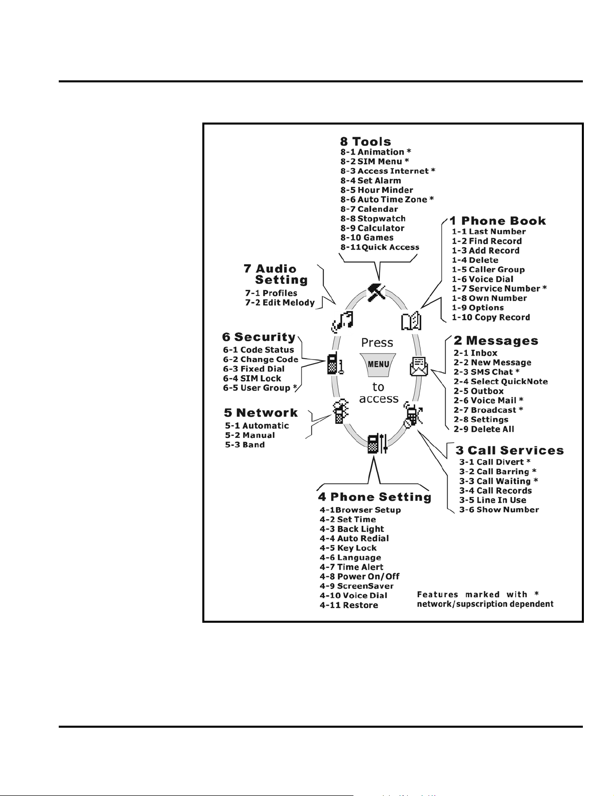
User Interface Menu Structure
Menu Navigation
C300 telephones are equipped with a simplified user-friendly interface that uses
soft keys and a 2-way scroll key to access phone functions and features. See Figure
1.
Active Line Identifies current active line.
Vibrate and Ring Your phone vibrates and rings when it receives a call.
Vibrate Only Your phone only vibrates without ringing when a call comes
in.
Battery Battery power level, the more bars, the more battery power.
Three bars: full. No bars: Recharging needed immediately.
The icon scrolls during charging until the battery is fully
charged.
Key lock Key lock is activated.
Roaming When phone is operated on a foreign network, this icon
displays.
“Soft keys” refer to non-labeled keys that correspond to text options displayed on
the screen. The left and right soft keys perform the function shown in the corners
of the display. The left key will usually select an option whereas the right key will
usually exit a function or return to a previous screen.
The menu key opens the initial menu structure, or allows access to a submenu
whenever displays on the screen. See Figure 3 for details of the menu structure.
12 October 14, 200 2 6881041B25
Page 17
Level 1 and 2 Service Manual General Operation
010717-o
Figure 3. Menu Structure
6881041B25 October 14, 2002 13
Page 18

General Operation Product Family C25
Alert Settings
C300 telephones include up to 32 preset alert tones and vibrations that can be
applied individually to specific alert events or to all events at the same time.
Pressing either volume key will mute the alert.
➧
Battery Function
Battery Gauge
The phone displays a battery-level indicator icon in the idle screen to indicate the
battery charge level. The gauge shows four levels: 100%, 66%, 33%, and Low
Battery.
Battery Removal
Removing the battery causes the phone to immediately shut down and any pending
work (for example, partially entered phone book entries or outgoing messages) is
lost.
Operation
E
G
➧
All batteries can cause property damage and/or bodily injury such as burns if a
conductive material such as jewelry, keys, or beaded chains touch exposed terminals.
The conductive material may complete an electrical circuit (short circuit) and
become quite hot. Exercise care in handling any charged battery, particularly when
placing it inside a pocket, purse, or other container with metal objects.
If the battery is removed while receiving a message, the message will be lost.
To ensure proper memory retention, turn the phone OFF before removing the
battery. Immediately replace the old battery with a fully charged battery.
For detailed operating instructions, refer to the appropriate User’s Guide listed in
the Related Publications section toward the end of this manual.
14 October 14, 200 2 6881041B25
Page 19

1 and 2
Level 1 and 2 Service Manual Tools and Test Equipment
6881041B25
C25
Tools and Test Equipment
The following tables list the tools and test equipment used on PF C25 (C300)
telephones. Use either the listed items or equivalents.
Table 3. General Test Equipment and Tools
Motorola
Part Number
See Table 6 Charger Used to charge battery and to power device
0180386A82
6680388B67 Disassembly tool, plastic with flat and pointed
RSX4043-A Torque Driver Used to remove and replace screws
6680388B01 Tweezers, plastic Used during assembly/disassembly
HP34401A
1. To order in North America, contact Motorola Aftermarket and Accessories Division (AAD) at (847) 538-8000;
Internationally, AAD can be reached by calling (847) 538-8023 or faxing (847) 576-3023.
2. Not available from Motorola. To order, contact Hewlett Packard at (800) 452-4844.
1
Antistatic Mat Kit (includes 66-80387A95 antistatic
mat, 66-80334B36 ground cord, and 42-80385A59
wrist band)
ends (manual opening tool)
Torque Driver Bit (long) T-5, Apex 440-5IP Torx
Plus or equivalent
2
Digital Multimeter Used to measure battery voltage
Description Application
Provides protection from damage to device caused
by electrostatic discharge (ESD)
Used during assembly/disassembly of device
Used with torque driver
6881041B25 October 14, 2002 15
Page 20

Disassembly Product Family C25
Disassembly
The procedures in this section provide instructions for the disassembly of PF C25
(C300) telephones. Tools and equipment used for the phone are listed in Table 3.
Many of the integrated devices used in this equipment are vulnerable to damage
G
G
from electrostatic discharge (ESD). Ensure adequate static protection is in place
when handling, shipping, and servicing the internal components of this equipment.
Avoid stressing the plastic in any way to avoid damage to either the plastic or
internal components.
16 October 14, 200 2 6881041B25
Page 21

Level 1 and 2 Service Manual Disassembly
Removing and Replacing the Battery Cover
1. Press down on the battery cover release and slide the battery cover away from
the phone as indicated in Figure 4.
BATTERY COVER RELEASE
BATTERY COVER
BATTERY COVER
020578o
Figure 4. Battery Cover Removal
2. To replace. Align the battery cover with the end of the phone and slide the
battery cover into position until it locks in place.
6881041B25 October 14, 2002 17
Page 22

Disassembly Product Family C25
Removing and Replacing the Battery
All batteries can cause property damage and/or bodily injury such as burns if a
conductive material such as jewelry, keys, or beaded chains touch exposed terminals.
E
The conductive material may complete an electrical circuit (short circuit) and
become quite hot. Exercise care in handling any charged battery, particularly when
placing it inside a pocket, purse, or other container with metal objects.
1. Ensure the phone is turned off.
2. Remove the battery cover as described in the procedures.
3. Lift the bottom end of the battery from the phone, then remove it completely
as shown in Figure 5.
BATTERY
020579o
Figure 5. Removing the Battery
There is a danger of explosion if the Nickel Metal Hydride battery is replaced
incorrectly. Replace only with the same type of battery or equivalent as recommended
E
18 October 14, 200 2 6881041B25
by the battery manufacturer. Dispose of used batteries according to the
manufacturer’s instructions.
Page 23

Level 1 and 2 Service Manual Disassembly
4. To replace, align the battery with the battery compartment so the contacts on
the battery match the battery contacts in the phone.
5. Slide the top of the battery into the receptacle molded into the housing, then
press the bottom end of the battery securely into the battery compartment until
it locks into place.
6. Replace the battery cover as described in the procedures.
Removing and Replacing the Subscriber Identity Module (SIM)
1. Remove the battery cover and battery as described in the procedures.
2. Slide the SIM in the direction of the arrow to remove it from the SIM holder
as shown in Figure 6.
SIM HOLDER
SIM
020580-o
Figure 6. Removing the SIM
3. To replace, carefully slide the SIM into the SIM holder. Be sure the SIM is
correctly positioned to contact the terminals.
4. Replace the battery, and battery cover as described in the procedures.
6881041B25 October 14, 2002 19
Page 24

Disassembly Product Family C25
Removing and Replacing the Antenna Cover
1. Remove the battery cover, battery, and SIM as described in the procedures.
2. The antenna cover is secured to the rear housing by three latches Their location
inside the antenna cover is indicated by the red arrows. Use the flat end of the
disassembly tool, beginning at the first location indicated by the red arrow to
carefully pry the antenna cover off of the rear housing. See Figure 7.
1
ANTENNA COVER
3
2
Figure 7. Removing the Antenna Cover
3. To replace, carefully align the antenna cover with the top of the rear housing.
4. Press the antenna cover firmly into place onto the rear housing.
5. Replace the SIM, battery, and battery cover as described in the procedures.
Removing and Replacing the Antenna Assembly
1. Remove the battery cover, battery, SIM, and antenna cover as described in the
procedures.
2. Using the Torx driver with a T5 bit, remove the 2 screws securing the antenna
as shown in Figure 9 and set aside for reuse.
020581-o
20 October 14, 200 2 6881041B25
Page 25

Level 1 and 2 Service Manual Disassembly
3. Insert the flat end of the disassembly tool between the antenna assembly and
the rear housing and gently pry the antenna out of the rear housing. See Figure
8.
ANTENNA
SCREWS
G
ANTENNA
DISASSEMBLY TOOL
020583-o
Figure 8. Removing the Antenna
Exercise caution when handling the antenna assembly to prevent damage to the
antenna connectors.
4. To replace, insert the widest edge of the antenna assembly carefully into
position in the rear housing, and then carefully press the top end of the antenna
into position. Be careful not to bend or otherwise damage the two antenna
connectors, ensuring they are correctly aligned to contact the transceiver board
when reassembled.
5. Replace the 2 screws and tighten firmly. Do not over tighten.
6. Replace the antenna cover, SIM, battery, and battery cover as described in the
procedures.
6881041B25 October 14, 2002 21
Page 26

Disassembly Product Family C25
Removing and Replacing the Rear Housing
This product contains static-sensitive devices. Use anti-static handling procedures
G
to prevent electrostatic discharge (ESD) and component damage.
G
1. Remove the battery cover, battery, SIM, and antenna cover as described in the
procedures.
2. Using the Torx driver with a T5 bit, remove the 4 screws shown in Figure 9
and set aside for reuse.
3. Carefully lift the rear housing away from the front housing as shown in
Figure 8.
SCREWS
SCREWS
REAR HOUSING
020582-o
Figure 9. Removing the Rear Housing
22 October 14, 200 2 6881041B25
Page 27

Level 1 and 2 Service Manual Disassembly
4. To replace, align the front housing with the rear housing then carefully press
together.
5. Replace the 4 screws and tighten firmly. Do not over tighten.
6. Replace the antenna cover, SIM, battery and battery cover as described in the
procedures.
6881041B25 October 14, 2002 23
Page 28

Disassembly Product Family C25
Removing and Replacing the Vibrator and Vibrator Grommet
1. Remove the battery cover, battery, SIM, antenna cover, and rear housing as
described in the procedures
VIBRATOR ASSEMBLY
FRONT HOUSING
.
VIBRATOR GROMMET
VIBRATOR MOTOR
020584-o
Figure 10. Removing the Vibrator and Vibrator Grommet
2. Turn the rear housing so the vibrator assembly is facing upward.
3. Using the flat end of the disassembly tool, carefully pry the vibrator assembly
from its cavity in the rear housing as shown in Figure 10. The assembly should
come away from the rear housing easily.
4. Separate the vibrator from the vibrator grommet.
5. To replace, insert the vibrator into the grommet. Ensure the vibrator shaft can
to rotate freely.
6. Align the vibrator assembly with the rear housing so the vibrator terminals
will contact the transceiver board contacts when reassembled, then press into
place until fully seated.
7. Replace the rear housing, antenna cover, SIM, battery, and battery cover as
described in the procedures.
24 October 14, 200 2 6881041B25
Page 29

Level 1 and 2 Service Manual Disassembly
Removing and Replacing the Transceiver Board
This product contains static-sensitive devices. Use anti-static handling procedures
G
to prevent electrostatic discharge (ESD) and component damage.
1. Remove the battery cover, battery, SIM, antenna cover, and rear housing as
described in the procedures
2. Using the flat end of the disassembly tool, carefully loosen the transceiver
board from the front housing.
.
DISASSEMBLY TOOL
TRANSCEIVER BOARD
Figure 11. Removing the Transceiver Board
3. Lift the transceiver board completely away from the front housing as shown
in Figure 11.
4. To replace, align the transceiver board with the front housing and gently press
into place.
➧
6881041B25 October 14, 2002 25
Ensure the keypad is correctly positioned in the front housing relative to the
transceiver board. Verify operation of the keys after replacing the transceiver board.
5. Replace the rear housing, antenna cover, SIM, battery and battery cover as
described in the procedures.
FRONT HOUSING
020585-o
Page 30

Disassembly Product Family C25
Removing and Replacing the RTC Battery
1. Remove the battery cover, battery, SIM, antenna cover, rear housing, and
transceiver board as described in the procedures
2. Use the flat end of the disassembly tool to pry the real time clock (RTC) battery
from its socket on the transceiver board. See Figure 12.
.
G
Dispose of used batteries according to the manufacturer’s instructions.
TRANSCEIVER BOARD
RTC BATTERY
020586-o
Figure 12. Removing the RTC Battery
3. To replace, align the new RTC battery with its socket so its positive terminal
is facing upward, then snap the battery in place until it is completely seated
in the socket.
4. Replace the transceiver board, rear housing, antenna cover, SIM, battery, and
battery cover as described in the procedures.
26 October 14, 200 2 6881041B25
Page 31

Level 1 and 2 Service Manual Disassembly
Removing and Replacing the Keypad
1. Remove the battery cover, battery, SIM, antenna cover, rear housing, and
transceiver board, as described in the procedures
.
FRONT HOUSING
PLASTIC TWEEZERS
Figure 13. Removing the Keypad
2. Lift the keypad from the front housing as shown in Figure 13.
3. To replace, insert the keypad into the front housing. Ensure the keys align
properly with the openings and the keypad is fully seated in the front housing.
4. Replace the transceiver board, rear housing, SIM, battery, and battery cover
as described in the procedures.
5. Verify correct operation.
KEYPAD
020587-o
6881041B25 October 14, 2002 27
Page 32

Disassembly Product Family C25
Removing and Replacing the Earpiece Speaker
1. Remove the battery cover, battery, SIM, antenna cover, rear housing, and
transceiver board as described in the procedures.
FRONT HOUSING
SPEAKER
G
DISASSEMBLY TOOL
020588-o
Figure 14. Removing the Earpiece Speaker
2. Using the flat end of the disassembly tool, pry the earpiece speaker from its
cavity in the front housing as shown in Figure 17.
The earpiece speaker is fastened to the front housing with adhesive. Exercise care
when removing to prevent damage to the front housing.
3. To replace the earpiece speaker, remove the protective backing from the new
earpiece speaker, then press the earpiece speaker into place in its front housing
cavity. Be sure the speaker is straight, fully seated within the cavity, and
positioned so its terminals will contact the transceiver board when
reassembled.
4. Replace the transceiver board, rear housing, antenna cover, SIM, battery, and
battery cover as described in the procedures.
28 October 14, 200 2 6881041B25
Page 33

Level 1 and 2 Service Manual Disassembly
Removing and Replacing the Microphone and Microphone Grommet
This product contains static-sensitive devices. Use anti-static handling procedures
G
to prevent electrostatic discharge (ESD) and component damage.
1. Remove the battery cover, battery, SIM, antenna cover, rear housing, and
transceiver board as described in the procedures
.
TRANSCEIVER BOARD
PLASTIC TWEEZERS
MICROPHONE ASSEMLBY
MICROPHONE
GROMMET
MICROPHONE
020690-o
Figure 15. Removing the Microphone and Microphone Grommet
2. Using the plastic tweezers, carefully pull the microphone assembly from its
socket on the transceiver board. The microphone assembly should come out of
its socket easily. See Figure 15.
3. Separate the microphone from the microphone grommet.
4. To replace, insert the microphone into the microphone grommet so the
terminals on the bottom of the microphone face inward. Ensure the microphone
is straight and pushed completely into the grommet.
6881041B25 October 14, 2002 29
Page 34

Disassembly Product Family C25
5. Align the microphone assembly with the microphone socket press into place
until fully seated.
The microphone assembly is keyed to fit the microphone socket only one way. Be
➧
sure the opening in the microphone grommet is positioned to face the opening in
the housing when reassembled.
6. Replace the transceiver board, rear housing, antenna cover, SIM, battery, and
battery cover as described in the procedures.
Removing and Replacing the Keypad Switch Dome Array
1. Remove the battery, SIM, and transceiver board as described in the procedures.
G
DISASSEMBLY
TOOL
SWITCH
DOME
ARRAY
TRANSCEIVER
BOARD
010711-o
Figure 16. Removing the Keypad Switch Dome Array
2. While holding the transceiver board stationary, carefully work the flat end of
the disassembly tool under a corner of the keypad switch dome array as shown
in Figure 19.
3. Slowly peel the keypad switch dome array from the transceiver board to
remove. Discard the keypad switch dome array just removed.
Do not touch the adhesive on the back of the keypad switch dome array or poor
adhesion and improper operation may result.
4. To replace, remove the protective backing from a new keypad switch array.
5. Align the new keypad switch dome array with the transceiver board.
30 October 14, 200 2 6881041B25
Page 35

Level 1 and 2 Service Manual Disassembly
6. Apply even pressure across the entire surface of the switch dome array to
ensure proper adhesion.
7. Replace the transceiver board, rear housing, SIM, and battery as described in
the procedures.
8. Verify correct operation.
6881041B25 October 14, 2002 31
Page 36

SIM Card and Identification Product Family C25
SIM Card and Identification
SIM Card
A SIM (Subscriber Identity Module) card is required to access the existing local
GSM network, or remote networks when traveling (if a roaming agreement has been
made with the provider).
The SIM card contains:
• All the data necessary to access GSM services
• The ability to store user information such as phone numbers.
• All information required by the network provider to provide access to the
network.
Identification
Each Motorola GSM device is labelled with a variety of identifying numbers.
The following information describes the current identifying labels.
Mechanical Serial Number (MSN)
The Mechanical Serial Number (MSN) is an individual unit identity number and
remains with the unit throughout the life of the unit.
The MSN can be used to log and track a unit on Motorola's Service Center Database.
The MSN is divided into 4 sections as shown in Figure 17.
MSN 10 Digits
3 Digits 1 Digit 2 Digits 4 Digits
APC DC DC SNR
Account Product Code
i.e. StarTAC Phone130
TM
Distribution Center
i.e. Easter Inch
Date Code: Year and
Month of Shipment
Unit's individual serial
number
000807-A
Figure 17. MSN Label Breakdown
International Mobile Station Equipment Identity (IMEI)
The International Mobile station Equipment Identity (IMEI) number is an
individual number unique to the PCB and is stored within the unit's memory. The
32 October 14, 200 2 6881041B25
Page 37

Level 1 and 2 Service Manual SIM Card and Identification
following diagram illustrates the various parts of this number as shown
in Figure 21.
IMEI 16 Digits
6 Digits 2 Digits 6 Digits 2 Digits
TAC FAC SNR IU
Type Approval Code Distribution Center
factory code
Individual PCB Serial
Number
Internal Use - spare
digits
000808-O
Figure 18. IMEI Label Breakdown
Other label number configurations present are:
• TRANSCEIVER NUMBER: Identifies the product type. Normally the SWF
number. (i.e. V100).
• PACKAGE NUMBER: Identifies the equipment type, mode, and language in
which the product is shipped.
6881041B25 October 14, 2002 33
Page 38

Troubleshooting Product Family C25
Troubleshooting
Manual Test Mode
Motorola PF C25 telephones are equipped with a manual test mode capability. This
allows service personnel to verify functionality and perform fault isolation by
entering keypad commands.
To enter the manual test command mode, a GSM / DCS test SIM must be used.
1. Press , to turn the phone OFF.
2. Remove the battery as described in the procedures.
3. Remove the customer’s SIM card from the phone as described in the procedures.
4. Insert the test SIM into the SIM slot.
5. Replace the battery as described in the procedures.
6. Press , to turn the phone ON.
7. Press and hold the # button for approximately 3 seconds until TEST displays
on the screen. The phone may now be issued test commands listed in Table 4.
Manual Test Mode Commands
Table 4. Test Commands
Test Command Test Function/Name
*#300# OK List Software and Hardware version
*#301# OK Full keypad functional test
*#302# OK Acoustic Test
1 - Greeting
2 - Main Vo lume Gain
3 - Input Cal
4 - Output Cal
5 - Side In Gain
6 - Vox Gain
7 - Min Mic Energy
8 - More
(a) - In Volume Gain
(b) - Aux Volume Gain
(c) - Silence Prd
(d) - Supp Prd
(e) - In Volume
(f) - Out Volume
(g) - Icon
(h) - Image
(i) - Animation
#303# OK Settings Saved
*#307# OK Engineering Test Mode
#400# OK ADC, Cal val
*#402# OK Adjust display Intensity/Contrast
*#403# OK List the Manufacturing Information
1998 0722 OK Master Unlock code for Phone and Sim Lock
1
1
1
1. Use with care - Contains calibration factors
34 October 14, 200 2 6881041B25
Page 39

Level 1 and 2 Service Manual Troubleshooting
Troubleshooting Chart
Table 5. PF C25 Telephones: Level 1 and 2 Troubleshooting Chart
SYMPTOM PROBABLE CAUSE VERIFICATION AND REMEDY
1. Telephone will not turn on or stay on. a) Battery either discharged or
2. Telephone exhibits poor reception or
erratic operation such as calls frequently
dropping or weak or distorted audio.
3. Display is erratic, or provides partial or
no display.
4. Incoming call alert transducer audio
distorted or volume is too low.
5. Telephone transmit audio is weak.
(usually indicated by called parties
complaining of difficulty in hearing voice).
6. Receive audio from earpiece speaker is
weak or distorted.
defective.
b) Battery terminals open or
misaligned.
c) Transceiver board assembly
defective.
a) Antenna assembly defective. Check to make sure that the antenna terminal
b) Transceiver board assembly
defective.
Transceiver board assembly defective. Replace the transceiver board assembly
a) Defective alert transducer. Replace alert transducer according to the
b) Faulty transceiver board assembly. Replace the transceiver board assembly
a) Microphone misaligned or
defective.
b) Transceiver board assembly
defective.
a) Earpiece speaker defective. T emporarily replace the earpiece speaker
Measure battery voltage across a 50 ohm
(>1 Watt) load. If the battery voltage is <3.25
Vdc, recharge the battery using the appropriate
battery charger. If the battery will not recharge,
replace the battery. If battery is not at fault,
proceed to b.
Visually inspect the battery terminals on both
the battery and the telephone. Realign and, if
necessary, either replace the battery or refer to
a Level 3 Service Center for the battery
connector replacement. If battery terminals are
not at fault, proceed to c.
Remove the transceiver board assembly.
Substitute a known good assembly and
temporarily reassemble the unit. Depress the
PWR button; if unit turns on and stays on,
disconnect the dc power source and reassemble
the telephone with the new transceiver board
assembly. Verify that the fault has been cleared.
makes proper contact with the transceiver board
assembly. If connected properly, substitute a
known good antenna. If the fault is still present,
proceed to b.
Replace the transceiver board assembly
(refer to 1c). Verify that the fault has been
cleared and reassemble the unit with the new
transceiver board assembly.
(refer to 1c). Verify that the fault has been
cleared and reassemble the unit with the new
transceiver board assembly.
procedures. If fault still present, proceed to b.
(refer to 1c). Verify that the fault has been
cleared and reassemble the unit with the new
transceiver board assembly.
Ensure microphone is correctly positioned in
socket. If fault still present, replace the
microphone as described in the procedures. If
fault is not cleared, proceed to b.
Replace the transceiver board assembly (refer
to 1c). Verify that the f ault has been cleared and
reassemble the unit with the new transceiver
board assembly.
assembly with a known good assembly. Ensure
good connection. Place a call and verify
improvement in earpiece audio. If fault is
cleared, reassemble the phone with the good
assembly. If fault is not cleared, proceed to b.
6881041B25 October 14, 2002 35
Page 40

Troubleshooting Product Family C25
Table 5. PF C25 Telephones: Level 1 and 2 Troubleshooting Chart (Continued)
SYMPTOM PROBABLE CAUSE VERIFICATION AND REMEDY
b) Transceiver board assembly
defective.
7. Telephone will not recognize or accept
SIM card.
8. Vibrator feature not functioning. a) Vibrator defective. Replace vibrator as described in the
9. Internal Charger not working. Faulty charger circuit on transceiver
10. No or weak audio when using headset. a) Headset plug not fully inserted. Ensure the headset plug is fully seated in the
a) SIM card defective. Check the SIM card contacts for dirt. Clean if
b) Transceiver board assembly
defective.
b) Transceiver board assembly
defective.
board assembly.
b) Faulty jack on transceiver board
assembly.
Replace the transceiver board assembly
(refer to 1c). Verify that the fault has been
cleared and reassemble with the new
transceiver board assembly.
necessary, and check if fault has been cleared.
If the contacts are clean, insert a known good
SIM card into the telephone. Power up the unit
and confirm that the card has been accepted. If
the fault no longer exists, replace the defecti ve
SIM card. If the SIM card is not at fault, proceed
to b.
Replace the transceiver board assembly
(refer to 1c). Verify that the fault has been
cleared and reassemble the unit with the new
transceiver board assembly.
procedures. If the fault has not been cleared,
proceed to b.
Replace the transceiver board assembly
(refer to 1c). Verify that the fault has been
cleared and reassemble the unit with the new
transceiver board assembly.
insert a known good discharged battery.
Connect a known good charger and verify
battery is being charged. If fault still present,
replace the transceiver board assembly (refer to
1c). Verify that the fault has been cleared and
reassemble the unit with the new transceiver
board assembly.
jack.
Replace the transceiver board assembly
(refer to 1c). Verify that the fault has been
cleared and reassemble the unit with the new
transceiver board assembly.
36 October 14, 200 2 6881041B25
Page 41

Level 1 and 2 Service Manual Troubleshooting
Programming: Software Upgrade and Flexing
The following hardware codes must be observed in the flashing software when the
phone is flashed:
Hardware
Code
ID1 EMEA
ID2 Asia
Region
If the phone is flexed with the wrong software, the phone displays the following
message: Invalid S/W load.
Contact your local technical support engineer for information about equipment and
procedures for flashing and flexing.
6881041B25 October 14, 2002 37
Page 42

Part Number Charts Product Family C25
Part Number Charts
The following charts are provided as a reference for the parts associated with
C300 telephones.
Exploded View Diagram
1
2
3
7
9
16
Figure 19. Exploded View Diagram
6
5
11
17
8
10
12
13
14
15
020618-o
38 October 14, 200 2 6881041B25
Page 43

Level 1 and 2 Service Manual Part Number Charts
Exploded View Parts List
Table 6. Exploded View Parts List
Item
Number
1 42.G2708.001 LCD lens assembly 10 39.G2712.001 Antenna cover
2 60.G2710.001 Front housing assembly 11 23.46002.001 Vibrator
3 23.40051.022 320 Ohm speaker 12 60.G2706.001 Rear housing
4 47.G2706.001 Keypad 13 29.90029.001 Antenna assembly
5 34.G2703.001 Membrane dial 14 86.00T03.2P2 Antenna assembly screws (2)
6 23.20059.001 Backup battery 15 60.G2712.011 Battery pack
7 23.42021.001 Microphone 16 See Table 7 Battery cover assembly
8 See Table 7 Transceiver PCB Assembly 17 86.00T03.2P1 Machine screws (4)
9 47.G0104.001 Microphone Grommet
Notes:
Motorola Part
Number
Description
Item
Number
Motorola Part
Number
Description
E
There is a danger of explosion if the Lithium ion battery pack is replaced incorrectly.
Replace only with the same type of battery or equivalent as recommended by the
battery manufacturer. Dispose of used batteries according to the manufacturer’s
instructions.
You can use the following link to order parts:
https://wissc.motorola.com/wissc_root/main/BrowserOK.html
A password is required.
For information on ordering parts for EMEA region please call +44 131 479 1274
For information on ordering spare parts for Asia, call +65 648 62995.
6881041B25 October 14, 2002 39
Page 44

Part Number Charts Product Family C25
Model-dependent Part Numbers
Table 7. Model-dependent Part Numbers
Item
Number
8 C300 , Silver, Thai SUG2778
8 C300, Dark blue, Thai SUG2779
8 C300, Silver, Simplified Chinese SUG2780
8 C300, Dark blue, Simplified Chinese SUG2781
8 C300, Pink, BPMF SUG2784
8 C300, Dark blue, English SUG2787
8 C300, Dark blue, Complex Chinese SUG2788
8 C300, Dark blue, BPMF SUG2789
8 C300, Silver, English SUG2790
8 C300, Silver, Complex Chinese SUG2791
8 C300, Silver, BPMF SUG2792
8 C300, Pink, Thai SUG2836
8 C300, Pink, Simplified Chinese SUG2837
8 C300, Pink, English SUG3314
8 C300, Pink, Complex Chinese SUG3315
16 Battery cover, Cosmic Blue SHN8207
16 Battery cover, Silver SHN8208
16 Battery cover, Shimmering Pink SHN9127
-
-
-
-
-
-
-
-
-
-
-
Part Description Part Number
40 October 14, 200 2 6881041B25
Page 45

Level 1 and 2 Service Manual Part Number Charts
Accessories
Table 8. Accessories
Part Description Part Number
Battery, EMEA, 550 mAh NiMH SNN5626
Battery, S. Asia, 550 mAh NiMH SNN5623
Battery, S.Asia, 600mAh Li-Ion SNN5647
Battery, China, 600 mAh Li-Ion SNN5648
Battery Charger, Hong Kong SPN4984
Battery Charger, China SPN4985
Battery Charger, US SPN4987
Battery Charger, Europe SPN4989
Battery Charger, UK SPN4990
Adapter, Euro Plug SPN4940
Vehicle Power Adapter SYN7818
Easy-Install Hands Free Car Kit (analog audio) SYN8597
Headset Ear bud – Silver AAYN4264
Lanyard SYN8392
Belt Clip, Black SYN8631
Pouch, Leather, Black MOTFL0074K
Pouch, Black & Light Grey w/ plastic front MOTFQ0075M
Pouch, Light Blue w/velcro MOTPT0076M
Pouch, Medium Blue MOTPT0076M
Related Publications
Motorola C300 User Guide, English 6881134B63
6881041B25 October 14, 2002 41
Page 46

Part Number Charts Product Family C25
42 October 14, 200 2 6881041B25
Page 47

1 and 2
Index
Level 1 and 2 Service Manual Index
C25
6881041B25
A
accessories
part numbers
alert modes
antenna cover, removing and replacing
antenna, removing and replacing
41
14
20
20
B
battery
function
gauge
removing
14
14
18
C
caller ID 7
Canadian Interference-Causing Equipment regulations
changes
product
closed user group
commands, manual test mode
controls
conventions
copyrights
computer software
1
7
34
9
3
2
product
IMEI
32
Introduction
1
1
K
keypad switch dome array, removing and replacing 30
keypad, removing and replacing
27
L
LCD 11
liquid crystal display (LCD)
11
M
manual test mode 34
microphone, removing and replacing
1
MSN
32
29
N
names
product
1
O
overview 6
D
disassembly 16
display animation
8
E
earpiece speaker, removing and replacing 28
exploded view diagram
exploded view parts list
38
39
F
FCC rules 1
features
6
call diverting
caller ID
text entry
voice recognition
Wireless Access Protocol (WAP)
8
7
7
7
7
I
identification 32
international mobile station equipment identity
mechanical serial number
32
32
P
part numbers
accessories
parts
38
exploded view diagram
exploded view parts list
product
changes
identification
names
publications, related
41
38
39
1
1
1
41
R
rear housing
removing
regulatory agency compliance
related publications
removing
antenna
antenna cover
battery
earpiece speaker
keypad
22
41
20
20
14
28
27
1
6881041B25 October 14, 2002 Index-1
Page 48

Running H/F 2
keypad switch dome array 30
microphone
rear housing
SIM card
transceiver board
replacing
antenna
antenna cover
earpiece speaker
keypad
keypad switch dome array
microphone
revisions
service manual
29
22
19
25
20
20
28
27
29
3
S
serial number
mechanical
service manual
about
revisions
scope
service policy
customer support
out of box failure
product support
shut down
upon battery removal
SIM card
removing
replacing
support
customer
product
32
2
3
2
3
4
3
3
32
19
19
4
3
14
30
W
WAP (Wireless Access Protocol) 7
warranty service
Wireless Access Protocol (WAP)
3
7
T
test equipment 15
text entry
tools
transceiver board
troubleshooting
7
15
removing
25
34
manual test mode
manual test mode commands
troubleshooting chart
34
35
34
V
voice recognition 7
Index-# Oct ober 14, 2002 Running H/F 3
Page 49

Page 50

MOTOROLA, the Stylized M Logo, and all other trademarks indicated as such herein are trademarks of Motorola, Inc.
All other product or service names are the property of their respective owners.
® Reg. U.S. Pat. & Tm. Off.
2002 Motorola, Inc.
All rights reserved.
Personal Communications Sector,
1500 Gateway Blvd.
Boynton Beach, FL 33426-8292
@6881041B25@
6881041B25-O
Page 51

../Graphics/020322-o.eps 1
../Graphics/020323-o.eps 9
../Graphics/idle screen.eps 11
../Graphics/010717-o.eps 13
../Graphics/020578-o.eps 17
../Graphics/020579-o.eps 18
../Graphics/020580-o.eps 19
../Graphics/020581-o.eps 20
../Graphics/020583-o.eps 21
../Graphics/020582-o.eps 22
../Graphics/020584-o.eps 24
../Graphics/020585-o.eps 25
../Graphics/020586-o.eps 26
../Graphics/020587-o.eps 27
../Graphics/020588-o.eps 28
../Graphics/020690-o.eps 29
../Graphics/010711-o.eps 30
../Graphics/000807-A.eps 32
../Graphics/000808-o.eps 33
../Graphics/020618-o.eps 38
Page 52

ScalaSans @ 24.0 pt 1
Times @ 12.0 pt 1
Motofont @ 80.0 pt 1
ScalaSans-Bold @ 40.0 pt 1
ScalaSans-Bold @ 30.0 pt 1
ScalaSans @ 20.0 pt 1
ScalaSans @ 15.0 pt 1
Helvetica @ 85.0 pt 1
Times @ 12.0 pt 2
Times @ 7.0 pt i
Helvetica @ 10.0 pt i
Helvetica @ 18.0 pt i
NewCenturySchlbk @ 10.0 pt i
NewCenturySchlbk @ 12.0 pt i
Times @ 12.0 pt i
Helvetica @ 7.0 pt ii
Helvetica @ 10.0 pt ii
Times @ 7.0 pt 1
Helvetica @ 10.0 pt 1
Helvetica @ 85.0 pt 1
Helvetica @ 18.0 pt 1
NewCenturySchlbk @ 10.0 pt 1
Helvetica @ 14.0 pt 1
NewCenturySchlbk @ 12.0 pt 1
Times @ 12.0 pt 1
Helvetica @ 7.0 pt 2
Helvetica @ 10.0 pt 2
Helvetica @ 85.0 pt 2
Helvetica @ 14.0 pt 2
NewCenturySchlbk @ 10.0 pt 2
Helvetica @ 12.0 pt 2
Times @ 12.0 pt 2
NewCenturySchlbk @ 12.0 pt 2
Times @ 7.0 pt 3
Helvetica @ 10.0 pt 3
Helvetica @ 85.0 pt 3
Helvetica @ 12.0 pt 3
NewCenturySchlbk @ 10.0 pt 3
ZapfDingbats @ 24.0 pt 3
ITCSymbol @ 24.0 pt 3
Techpubskeycap @ 14.0 pt 3
Helvetica @ 9.0 pt 3
MongooseText @ 8.0 pt 3
Mauitext @ 11.0 pt 3
Bravo @ 9.0 pt 3
BeepwearLED @ 8.0 pt 3
Helvetica @ 14.0 pt 3
Helvetica @ 7.0 pt 4
Helvetica @ 10.0 pt 4
Helvetica @ 85.0 pt 4
Helvetica @ 12.0 pt 4
NewCenturySchlbk @ 10.0 pt 4
Helvetica @ 14.0 pt 4
Helvetica @ 9.0 pt 4
Page 53

Times @ 7.0 pt 5
Helvetica @ 10.0 pt 5
Helvetica @ 85.0 pt 5
Helvetica @ 18.0 pt 5
Times @ 12.0 pt 5
Helvetica @ 9.0 pt 5
Helvetica @ 7.0 pt 6
Helvetica @ 10.0 pt 6
Helvetica @ 85.0 pt 6
Helvetica @ 18.0 pt 6
NewCenturySchlbk @ 10.0 pt 6
Helvetica @ 14.0 pt 6
Times @ 7.0 pt 7
Helvetica @ 10.0 pt 7
Helvetica @ 85.0 pt 7
Helvetica @ 12.0 pt 7
NewCenturySchlbk @ 10.0 pt 7
ZapfDingbats @ 24.0 pt 7
Times @ 12.0 pt 7
Helvetica @ 7.0 pt 8
Helvetica @ 10.0 pt 8
Helvetica @ 85.0 pt 8
NewCenturySchlbk @ 10.0 pt 8
ZapfDingbats @ 24.0 pt 8
Helvetica @ 12.0 pt 8
Times @ 7.0 pt 9
Helvetica @ 10.0 pt 9
Helvetica @ 85.0 pt 9
Helvetica @ 18.0 pt 9
Helvetica @ 14.0 pt 9
NewCenturySchlbk @ 10.0 pt 9
Helvetica @ 2.0 pt 9
Helvetica @ 7.0 pt 9
Helvetica @ 12.0 pt 9
Helvetica @ 9.0 pt 9
C300 @ 18.0 pt 9
Times @ 10.0 pt 9
Helvetica @ 7.0 pt 10
Helvetica @ 10.0 pt 10
Helvetica @ 85.0 pt 10
C300 @ 18.0 pt 10
Times @ 10.0 pt 10
Times @ 9.5 pt 10
Times @ 7.0 pt 11
Helvetica @ 10.0 pt 11
Helvetica @ 85.0 pt 11
Helvetica @ 12.0 pt 11
NewCenturySchlbk @ 10.0 pt 11
Times @ 12.0 pt 11
ZapfDingbats @ 24.0 pt 11
Helvetica @ 14.0 pt 11
Helvetica @ 2.0 pt 11
Helvetica @ 7.0 pt 11
Helvetica @ 9.0 pt 11
Page 54

SYNICN12 @ 18.0 pt 11
C300 @ 18.0 pt 11
Courier @ 10.0 pt 11
Times @ 9.5 pt 11
Helvetica @ 7.0 pt 12
Helvetica @ 10.0 pt 12
Helvetica @ 85.0 pt 12
NewCenturySchlbk @ 10.0 pt 12
Helvetica @ 14.0 pt 12
Helvetica @ 12.0 pt 12
SYNICN12 @ 18.0 pt 12
Times @ 7.0 pt 13
Helvetica @ 10.0 pt 13
Helvetica @ 85.0 pt 13
NewCenturySchlbk @ 10.0 pt 13
Helvetica @ 2.0 pt 13
Helvetica @ 7.0 pt 13
Helvetica @ 7.0 pt 14
Helvetica @ 10.0 pt 14
Helvetica @ 85.0 pt 14
Helvetica @ 14.0 pt 14
NewCenturySchlbk @ 10.0 pt 14
Times @ 12.0 pt 14
ZapfDingbats @ 24.0 pt 14
Helvetica @ 12.0 pt 14
ITCSymbol @ 36.0 pt 14
Times @ 7.0 pt 15
Helvetica @ 10.0 pt 15
Helvetica @ 85.0 pt 15
Helvetica @ 18.0 pt 15
NewCenturySchlbk @ 10.0 pt 15
Times @ 12.0 pt 15
Helvetica @ 9.0 pt 15
NewCenturySchlbk @ 12.0 pt 15
Helvetica @ 7.0 pt 16
Helvetica @ 10.0 pt 16
Helvetica @ 85.0 pt 16
Helvetica @ 18.0 pt 16
NewCenturySchlbk @ 10.0 pt 16
Times @ 12.0 pt 16
ITCSymbol @ 36.0 pt 16
Times @ 7.0 pt 17
Helvetica @ 10.0 pt 17
Helvetica @ 85.0 pt 17
Helvetica @ 14.0 pt 17
NewCenturySchlbk @ 10.0 pt 17
Helvetica @ 9.0 pt 17
Helvetica @ 7.0 pt 17
Helvetica @ 7.0 pt 18
Helvetica @ 10.0 pt 18
Helvetica @ 85.0 pt 18
Helvetica @ 14.0 pt 18
Times @ 12.0 pt 18
ITCSymbol @ 36.0 pt 18
Page 55

NewCenturySchlbk @ 10.0 pt 18
Helvetica @ 2.0 pt 18
Times @ 7.0 pt 19
Helvetica @ 10.0 pt 19
Helvetica @ 85.0 pt 19
NewCenturySchlbk @ 10.0 pt 19
Helvetica @ 14.0 pt 19
Times @ 12.0 pt 19
Helvetica @ 2.0 pt 19
Helvetica @ 7.0 pt 19
Helvetica @ 7.0 pt 20
Helvetica @ 10.0 pt 20
Helvetica @ 85.0 pt 20
Helvetica @ 14.0 pt 20
NewCenturySchlbk @ 10.0 pt 20
Helvetica @ 2.0 pt 20
Times @ 7.0 pt 21
Helvetica @ 10.0 pt 21
Helvetica @ 85.0 pt 21
NewCenturySchlbk @ 10.0 pt 21
Times @ 10.0 pt 21
Times @ 12.0 pt 21
Helvetica @ 2.0 pt 21
Helvetica @ 7.0 pt 21
ITCSymbol @ 36.0 pt 21
Helvetica @ 7.0 pt 22
Helvetica @ 10.0 pt 22
Helvetica @ 85.0 pt 22
Helvetica @ 14.0 pt 22
Times @ 12.0 pt 22
NewCenturySchlbk @ 10.0 pt 22
ITCSymbol @ 36.0 pt 22
Helvetica @ 9.0 pt 22
Times @ 7.0 pt 23
Helvetica @ 10.0 pt 23
Helvetica @ 85.0 pt 23
NewCenturySchlbk @ 10.0 pt 23
Helvetica @ 7.0 pt 24
Helvetica @ 10.0 pt 24
Helvetica @ 85.0 pt 24
Helvetica @ 14.0 pt 24
NewCenturySchlbk @ 10.0 pt 24
Times @ 12.0 pt 24
Helvetica @ 2.0 pt 24
Times @ 7.0 pt 25
Helvetica @ 10.0 pt 25
Helvetica @ 85.0 pt 25
Helvetica @ 14.0 pt 25
Times @ 12.0 pt 25
ITCSymbol @ 36.0 pt 25
NewCenturySchlbk @ 10.0 pt 25
Helvetica @ 2.0 pt 25
Helvetica @ 7.0 pt 25
ZapfDingbats @ 24.0 pt 25
Page 56

Helvetica @ 7.0 pt 26
Helvetica @ 10.0 pt 26
Helvetica @ 85.0 pt 26
Helvetica @ 14.0 pt 26
NewCenturySchlbk @ 10.0 pt 26
Times @ 12.0 pt 26
ITCSymbol @ 36.0 pt 26
Helvetica @ 2.0 pt 26
Times @ 7.0 pt 27
Helvetica @ 10.0 pt 27
Helvetica @ 85.0 pt 27
Helvetica @ 14.0 pt 27
NewCenturySchlbk @ 10.0 pt 27
Times @ 12.0 pt 27
Helvetica @ 2.0 pt 27
Helvetica @ 7.0 pt 27
Helvetica @ 7.0 pt 28
Helvetica @ 10.0 pt 28
Helvetica @ 85.0 pt 28
Helvetica @ 14.0 pt 28
NewCenturySchlbk @ 10.0 pt 28
Times @ 12.0 pt 28
Helvetica @ 2.0 pt 28
ITCSymbol @ 36.0 pt 28
Times @ 7.0 pt 29
Helvetica @ 10.0 pt 29
Helvetica @ 85.0 pt 29
Helvetica @ 14.0 pt 29
Times @ 12.0 pt 29
ITCSymbol @ 36.0 pt 29
NewCenturySchlbk @ 10.0 pt 29
Helvetica @ 2.0 pt 29
Helvetica @ 7.0 pt 29
Helvetica @ 7.0 pt 30
Helvetica @ 10.0 pt 30
Helvetica @ 85.0 pt 30
NewCenturySchlbk @ 10.0 pt 30
Times @ 12.0 pt 30
ZapfDingbats @ 24.0 pt 30
Helvetica @ 14.0 pt 30
Helvetica @ 2.0 pt 30
ITCSymbol @ 36.0 pt 30
Times @ 7.0 pt 31
Helvetica @ 10.0 pt 31
Helvetica @ 85.0 pt 31
NewCenturySchlbk @ 10.0 pt 31
Helvetica @ 7.0 pt 32
Helvetica @ 10.0 pt 32
Helvetica @ 85.0 pt 32
Helvetica @ 18.0 pt 32
Helvetica @ 14.0 pt 32
NewCenturySchlbk @ 10.0 pt 32
Helvetica @ 12.0 pt 32
Helvetica @ 2.0 pt 32
Page 57

Times @ 7.0 pt 33
Helvetica @ 10.0 pt 33
Helvetica @ 85.0 pt 33
NewCenturySchlbk @ 10.0 pt 33
Times @ 12.0 pt 33
Helvetica @ 2.0 pt 33
Helvetica @ 7.0 pt 33
Helvetica @ 7.0 pt 34
Helvetica @ 10.0 pt 34
Helvetica @ 85.0 pt 34
Helvetica @ 18.0 pt 34
Helvetica @ 14.0 pt 34
NewCenturySchlbk @ 10.0 pt 34
CamelotGrafix @ 10.0 pt 34
CamelotText @ 10.0 pt 34
Times @ 12.0 pt 34
Helvetica @ 9.0 pt 34
Times @ 7.0 pt 35
Helvetica @ 10.0 pt 35
Helvetica @ 85.0 pt 35
Helvetica @ 14.0 pt 35
Times @ 12.0 pt 35
Helvetica @ 9.0 pt 35
Helvetica @ 7.0 pt 36
Helvetica @ 10.0 pt 36
Helvetica @ 85.0 pt 36
Helvetica @ 9.0 pt 36
Times @ 7.0 pt 37
Helvetica @ 10.0 pt 37
Helvetica @ 85.0 pt 37
Helvetica @ 14.0 pt 37
NewCenturySchlbk @ 10.0 pt 37
Helvetica @ 9.0 pt 37
Helvetica @ 8.0 pt 37
Courier @ 10.0 pt 37
Helvetica @ 7.0 pt 38
Helvetica @ 10.0 pt 38
Helvetica @ 85.0 pt 38
Helvetica @ 18.0 pt 38
NewCenturySchlbk @ 10.0 pt 38
Helvetica @ 14.0 pt 38
Helvetica @ 2.0 pt 38
Times @ 7.0 pt 39
Helvetica @ 10.0 pt 39
Helvetica @ 85.0 pt 39
Helvetica @ 14.0 pt 39
Times @ 12.0 pt 39
Helvetica @ 9.0 pt 39
Helvetica @ 8.0 pt 39
ITCSymbol @ 36.0 pt 39
NewCenturySchlbk @ 10.0 pt 39
Helvetica @ 7.0 pt 40
Helvetica @ 10.0 pt 40
Helvetica @ 85.0 pt 40
Page 58

Helvetica @ 14.0 pt 40
Times @ 12.0 pt 40
Helvetica @ 9.0 pt 40
Times @ 7.0 pt 41
Helvetica @ 10.0 pt 41
Helvetica @ 85.0 pt 41
Helvetica @ 14.0 pt 41
Times @ 12.0 pt 41
Helvetica @ 9.0 pt 41
NewCenturySchlbk @ 10.0 pt 41
Helvetica @ 7.0 pt 42
Helvetica @ 10.0 pt 42
Helvetica @ 85.0 pt 42
Times @ 7.0 pt 1
Helvetica @ 10.0 pt 1
Helvetica @ 13.0 pt 1
Times @ 12.0 pt 1
NewCenturySchlbk @ 12.0 pt 1
Helvetica @ 7.0 pt 2
Helvetica @ 10.0 pt 2
Times @ 12.0 pt 2
Helvetica @ 13.0 pt 2
NewCenturySchlbk @ 24.0 pt 1
NewCenturySchlbk @ 24.0 pt 2
Helvetica @ 7.0 pt 2
Symbol @ 8.0 pt 2
BarcodeThreeOfNine @ 24.0 pt 2
Helvetica @ 12.0 pt 2
Times New Roman @ 12.0 pt 1
Times New Roman @ 12.0 pt 1
Times New Roman @ 12.0 pt 2
Times New Roman @ 12.0 pt 3
Times New Roman @ 12.0 pt 4
Times New Roman @ 12.0 pt 5
Times New Roman @ 12.0 pt 6
Times New Roman @ 12.0 pt 7
 Loading...