

Page 1
Air Handling Unit Controller
PAC-AH125, 140, 250M-H
FOR INSTALLER
INSTALLATION MANUAL
For safe and correct use, please read this installation manual thoroughly before installing the controller.
GB
Page 2
2
[Fig. 2.0.1]
12 3
456
3
[Fig. 3.0.1]
7
D
8
1 Controller
2 LEV-kit
3 Thermistor
4 Clip
5 Insulation
6 Tie band
7 Installation manual
8 Tube
C
A
E
B
L
K
H
I
J
F
G
A Air handling unit controller (PAC-AH · M-H)
B Air handling unit (field supply)
C Controller (field supply)
D Outdoor unit
E Heat exchanger (field supply)
F Gas pipe
G Liquid pipe
H LEV-kit
I Thermistor (gas pipe)
J Thermistor (liquid pipe)
K Thermistor (suction air)
L Thermistor (discharge air)
2
Page 3
4
[Fig. 4.2.1]
B
A Controller
B Screw (field supply)
6
[Fig. 6.2.1]
A
A Remove the cap
A
410
260
[Fig. 6.2.2]
A
B
D
C
C
Type 63 - 140
A Heat exchanger (field supply)
B LEV-kit
C Brazing
D Linear expansion valve
E Outdoor unit
E
[Fig. 6.2.3]
[Fig. 6.3.0.1]
B
H
A
D
C
FF
C
G
B
Type 250
A
A Most sensitive point of the
thermistor
B
B Maximize the contact
G
E
H
[Fig. 6.3.0.2]
A Heat exchanger (field supply)
B LEV-kit
C Brazing
D Linear expansion valve
E Outdoor unit
F Refrigerant pipe size ø9.52 (field supply)
G Distributor (field supply)
H Refrigerant pipe size ø9.52 (field supply)
3
Page 4
6
[Fig. 6.3.2]
[Fig. 6.3.1]
A
B
D
E
C
F
A Heat exchanger (field supply)
B Gas pipe
C Thermistor (gas pipe)
D Aluminum tape (field supply)
E Insulation
F Tie band
A
B
G
[Fig. 6.3.3]
7
[Fig. 7.0.1]
D
C
C
B
E
F
D
A Heat exchanger (field supply)
B Gas pipe
C Thermistor (liquid pipe)
D Aluminum tape (field supply)
E Insulation
F Tie band
G Capillary tube
A
B
A
C
A Thermistor (suction/discharge air)
B Clip
C Screw (field supply)
D Plate (field supply)
A
A Outer cover
B
CN31
SW3
SW1
CN20
CN21
CN29
CN22
CN30
CN32
G
CN2M
SW2
SW4
CN3T
SW7
F
T31
A2
v
K
T32
A1
T21
P
T22
T11
Q
T12
D2
L
T1
D1
W
T2
D12
M
White
D11
Yellow
R
Green
Black
D22
N
Red
C
D21
D32
D31
Brown
O
M1
IH
2
1
E
J
M2
S
D
B Inner cover
C Terminal block TB2
D Terminal block TB5
E Terminal block TB15
F Terminal block TBX
G Terminal block TB4
H Power supply (208 - 240 V)/Ear th
I To outdoor unit
J To remote controller
K Distant signal (ON/OFF)
L Operation signal
M Error signal
N Fan signal
O Defrost signal
P Thermistor (gas pipe)
Q Thermistor (liquid pipe)
R LEV-kit
S Distant signal
T Thermistor
U Transmission
V Thermistor (suction air)
W Thermistor (discharge air)
UTRSH
4
Page 5
7
[Fig. 7.1.1]
AB D
[Fig. 7.2.1] [Fig. 7.2.2]
B
M1M2 21 21
TB3
SM1M2 SM1M2
TB5 TB15 TB5 TB15
[Fig. 7.2.3] [Fig. 7.2.4]
2
1
DC10~13 V
B
AB
12
E
CCC
AA
TB3
CC
A
M1M2
B
A Switch 16 A B Overcurrent protection 16 A
C Indoor unit D Total operating current be less than 16 A
E Pull box
AA
SM1M2 SM1M2
TB5 TB5
A Terminal block for AHU controller/
indoor transmission cable
B Terminal block for outdoor trans-
mission cable
C Remote controller
A Non-polarized
B Remote Controller
M2
M1
DC24~30 V
12
(A, B)
CC
S
A
B
[Fig. 7.4.1]
8
[Fig. 8.1.1]
B
B
C
A Bunch of wires
D
A
B Plug
C Tube
D Insulation tape
9
[Fig. 9.0.1]
A
A Address switch
B SW2
5
Page 6
Contents
1. Safety precautions ...................................................................................... 6
1.1. Before installation and electric work .......................................... 6
1.2. Precautions for devices that use R410A refrigerant .................. 6
1.3. Before getting installed .............................................................. 7
1.4. Before getting installed (moved) - electrical work ...................... 7
1.5. Before starting the test run ........................................................ 7
2. Accessories ................................................................................................ 7
3. System component ..................................................................................... 8
3.1. Selection of the heat exchanger (air handling unit) ................... 8
4. Selecting an installation site and installing the controller ............................ 9
4.1. Combining indoor units with outdoor units ................................ 9
4.2. Installing the controller .............................................................. 9
5. Refrigerant pipe specifications .................................................................... 9
6. Connecting refrigerant pipes ....................................................................... 9
6.1. Refrigerant piping work ............................................................. 9
1. Safety precautions
1.1. Before installation and electric work
GBDFEINLPGRRUTR
s Before installing the unit, make sure you read all the “Safety
precautions”.
s The “Safety precautions” provide very important points re-
garding safety. Make sure you follow them.
Symbols used in the text
Warning:
Describes precautions that should be observed to prevent danger of injury
or death to the user.
Caution:
Describes precautions that should be observed to prevent damage to the
unit.
Symbols used in the illustrations
: Indicates an action that must be avoided.
: Indicates that important instructions must be followed.
: Indicates a part which must be grounded.
: Indicates that caution should be taken with rotating parts. (This symbol is
displayed on the main unit label.) <Color: yellow>
: Beware of electric shock (This symbol is displayed on the main unit label.)
<Color: yellow>
Warning:
Carefully read the labels affixed to the main unit.
Warning:
• Ask the dealer or an authorized technician to install the controller.
- Improper installation by the user may result in water leakage, electric shock,
or fire.
• Use the specified cables for wiring. Make the connections securely so
that the outside force of the cable is not applied to the terminals.
- Inadequate connection and fastening may generate heat and cause a fire.
• Prepare for typhoons and other strong winds and earthquakes and install the unit at the specified place.
- Improper installation may cause the unit to topple and result in injury.
• Never repair the unit. If the controller must be repaired, consult the dealer.
- If the unit is repaired improperly, electric shock, or fire may result.
• When handling this product, always wear protective equipment.
EG: Gloves, full arm protection namely boiler suit, and safety glasses.
- Improper handling may result in injury.
• If refrigerant gas leaks during installation work, ventilate the room.
- If the refrigerant gas comes into contact with a flame, poisonous gases will
CZSVHGPO
be released.
• Install the controller according to this Installation Manual.
- If the unit is installed improperly, electric shock, or fire may result.
• Have all electric work done by a licensed electrician according to “Electric Facility Engineering Standard” and “Interior Wire Regulations” and
the instructions given in this manual and always use a special circuit.
- If the power source capacity is inadequate or electric work is performed im-
properly, electric shock and fire may result.
• Keep the electric parts away from water (washing water etc.).
- It might result in electric shock, catching fire or smoke.
• Securely install the outdoor unit terminal cover (panel).
- If the terminal cover (panel) is not installed properly, dust or water may enter
the outdoor unit and fire or electric shock may result.
6
6.2. Liner expansion valve piping work ............................................. 9
6.3. Thermistor setting work ............................................................. 9
7. Electrical wiring ......................................................................................... 10
7.1. Power supply wiring ................................................................. 11
7.2. Connecting remote controller, AHU controller and outdoor
transmission cables ................................................................. 11
7.3. Connecting LEV-kit and thermistor cables .............................. 11
7.4. Connecting distant signal line .................................................. 11
7.5. External I/O specifications ....................................................... 12
8. Setting switches ........................................................................................ 12
8.1. Setting addresses .................................................................... 12
8.2. Setting unit capacity ................................................................ 12
8.3. Setting temperature control ..................................................... 13
8.4. Dip-switch function .................................................................. 13
9. Initial setting and test run .......................................................................... 13
• When installing and moving the air handling unit to another site, do not
charge the it with a refrigerant different from the refrigerant specified on
the unit.
- If a different refrigerant or air is mixed with the original refrigerant, the refrig-
erant cycle may malfunction and the unit may be damaged.
• If the air handling unit is installed in a small room, measures must be
taken to prevent the refrigerant concentration from exceeding the safety
limit even if the refrigerant should leak.
- Consult the dealer regarding the appropriate measures to prevent the safety
limit from being exceeded. Should the refrigerant leak and cause the safety
limit to be exceeded, hazards due to lack of oxygen in the room could result.
• When moving and reinstalling the air handling unit, consult the dealer or
an authorized technician.
- If the controller is installed improperly, electric shock, or fire may result.
• After completing installation work, make sure that refrigerant gas is not
leaking.
- If the refrigerant gas leaks and is exposed to a fan heater, stove, oven, or
other heat source, it may generate noxious gases.
• Do not reconstruct or change the settings of the protection devices.
- If the pressure switch, thermal switch, or other protection device is shorted
and operated forcibly, or parts other than those specified by Mitsubishi Electric are used, fire or explosion may result.
• To dispose of this product, consult your dealer.
• Do not use a leak detection additive.
1.2. Precautions for devices that use R410A
refrigerant
Caution:
• Do not use the existing refrigerant piping.
- The old refrigerant and refrigerator oil in the existing piping contains a large
amount of chlorine which may cause the refrigerator oil of the new unit to
deteriorate.
• Use refrigerant piping made of C1220 (Cu-DHP) phosphorus deoxidized
copper as specified in the JIS H3300 “Copper and copper alloy seamless
pipes and tubes”. In addition, be sure that the inner and outer surfaces of
the pipes are clean and free of hazardous sulphur, oxides, dust/dirt, shaving particles, oils, moisture, or any other contaminant.
- Contaminants on the inside of the refrigerant piping may cause the refriger-
ant residual oil to deteriorate.
• Store the piping to be used during installation indoors and keep both
ends of the piping sealed until just before brazing. (Store elbows and
other joints in a plastic bag.)
- If dust, dirt, or water enters the refrigerant cycle, deterioration of the oil and
compressor trouble may result.
• Use ester oil, ether oil or alkylbenzene (small amount) as the refrigerator
oil to coat flares and flange connections.
- The refrigerator oil will degrade if it is mixed with a large amount of mineral
oil.
• Use liquid refrigerant to fill the system.
- If gas refrigerant is used to seal the system, the composition of the refriger-
ant in the cylinder will change and performance may drop.
• Do not use a refrigerant other than R410A.
- If another refrigerant (R22, etc.) is used, the chlorine in the refrigerant may
cause the refrigerator oil to deteriorate.
• Use a vacuum pump with a reverse flow check valve.
- The vacuum pump oil may flow back into the refrigerant cycle and cause the
refrigerator oil to deteriorate.
• Do not use the following tools that are used with conventional refrigerants.
(Gauge manifold, charge hose, gas leak detector, reverse flow check valve,
refrigerant charge base, vacuum gauge, refrigerant recovery equipment.)
- If the conventional refrigerant and refrigerator oil are mixed in the R410A,
the refrigerant may deteriorated.
Page 7

- If water is mixed in the R410A, the refrigerator oil may deteriorate.
- Since R410A does not contain any chlorine, gas leak detectors for conventional refrigerants will not react to it.
• Do not use a charging cylinder.
- Using a charging cylinder may cause the refrigerant to deteriorate.
• Be especially careful when managing the tools.
- If dust, dirt, or water gets in the refrigerant cycle, the refrigerant may deteriorate.
1.3. Before getting installed
Caution:
• Do not install the unit where combustible gas may leak.
- If the gas leaks and accumulates around the unit, an explosion may result.
• Do not use the air conditioner where food, pets, plants, precision instruments, or artwork are kept.
- The quality of the food, etc. may deteriorate.
• Do not use the air conditioner in special environments.
- Oil, steam, sulfuric smoke, etc. can significantly reduce the performance of
the air conditioner or damage its parts.
• When installing the unit in a hospital, communication station, or similar
place, provide sufficient protection against noise.
- The inverter equipment, private power generator, high-frequency medical
equipment, or radio communication equipment may cause the air conditioner
to operate erroneously, or fail to operate. On the other hand, the air conditioner may affect such equipment by creating noise that disturbs medical
treatment or image broadcasting.
• Do not install the unit on a structure that may cause leakage.
- When the room humidity exceeds 80 % or when the drain pipe is clogged,
condensation may drip from the indoor unit. Perform collective drainage work
together with the outdoor unit, as required.
1.4. Before getting installed (moved) - elec-
trical work
Caution:
• Ground the unit.
- Do not connect the ground wire to gas or water pipes, lightning rods, or
telephone ground lines. Improper grounding may result in electric shock.
• Install the power cable so that tension is not applied to the cable.
- Tension may cause the cable to break and generate heat and cause a fire.
• Install an leak circuit breaker, as required.
- If an leak circuit breaker is not installed, electric shock may result.
• Use power line cables of sufficient current carrying capacity and rating.
- Cables that are too small may leak, generate heat, and cause a fire.
• Use only a circuit breaker and fuse of the specified capacity.
- A fuse or circuit breaker of a larger capacity or a steel or copper wire may
result in a general unit failure or fire.
• Do not wash the air conditioner units.
- Washing them may cause an electric shock.
• Be careful that the installation base is not damaged by long use.
- If the damage is left uncorrected, the unit may fall and cause personal injury
or property damage.
• Be very careful about product transportation.
- Only one person should not carr y the product if it weighs more than 20 kg.
- Some products use PP bands for packaging. Do not use any PP bands for a
means of transportation. It is dangerous.
- Do not touch the heat exchanger fins. Doing so may cut your fingers.
- When transporting the outdoor unit, suspend it at the specified positions on
the unit base. Also support the outdoor unit at four points so that it cannot
slip sideways.
• Safely dispose of the packing materials.
- Packing materials, such as nails and other metal or wooden parts, may cause
stabs or other injuries.
- Tear apart and throw away plastic packaging bags so that children will not
play with them. If children play with a plastic bag which was not torn apar t,
they face the risk of suffocation.
1.5. Before starting the test run
Caution:
• Turn on the power at least 12 hours before starting operation.
- Star ting operation immediately after turning on the main power switch can
result in severe damage to internal parts. Keep the power switch turned on
during the operational season.
• Do not touch the switches with wet fingers.
- Touching a switch with wet fingers can cause electric shock.
• Do not touch the refrigerant pipes during and immediately after operation.
- During and immediately after operation, the refrigerant pipes are may be hot
and may be cold, depending on the condition of the refrigerant flowing through
the refrigerant piping, compressor, and other refrigerant cycle parts. Your
hands may suffer burns or frostbite if you touch the refrigerant pipes.
• Do not operate the air conditioner with the panels and guards removed.
- Rotating, hot, or high-voltage parts can cause injuries.
• Do not turn off the power immediately after stopping operation.
- Always wait at least five minutes before turning off the power. Otherwise,
water leakage and trouble may occur.
GBDFEINLPGRRUTRCZSVHGPO
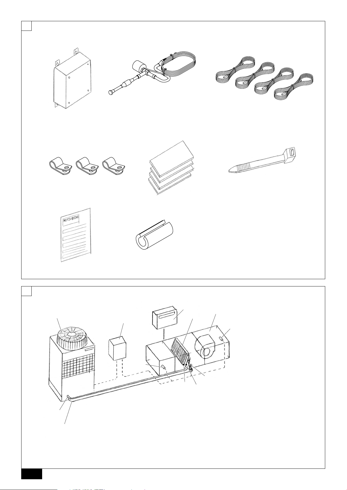
2. Accessories
The unit is provided with the following accessories:
[Fig. 2.0.1] (P.2)
No. Accessories
1 Controller 1 1 1
LEV-kit (EDM804) 1 0 2
2
LEV-kit (EDM1004) 0 1 0
3 Thermistor 4 4 4
4 Clip (1 spare) 3 3 3
5 Insulation (2 spares) 4 4 4
6 Tie band (2 spares) 6 6 6
7 Installation manual 1 1 1
8 Tube 5 5 5
AH125 AH140 AH250
Quantity
7
Page 8

3. System component
[Fig. 3.0.1] (P.2)
A Air handling unit controller (PAC-AH · M-H)
B Air handling unit (field supply)
C Controller (field supply)
D Outdoor unit
E Heat exchanger (field supply)
F Gas pipe
G Liquid pipe
H LEV-kit
I Thermistor (gas pipe)
J Thermistor (liquid pipe)
K Thermistor (suction air)
L Thermistor (discharge air)
3.1. Selection of the heat exchanger (air handling unit)
3.1.1 Compressive strength
The design pressure of this system is 4.15MPa. The compressive strength of the
GBDFEINLPGRRUTR
evaporator and of other pipes must exceed 12.45MPa (=4.15 × 3).
3.1.2 Contamination control
Control the contamination to keep proper quality of the models using HFC refrigerant.
Contamination
Residual water content
Residual oil content
Residual foreign substance
(including residual machining
oil content)
Others
The content shall be less than [10 mg/lit.].
The low residual oil pipe [0.5 mg/m or less] shall
be used for heat exchangers.
For long piping connected or piping tended to be
stagnated with oil, the content shall be less than
[3 mg/m]. For other piping, [9 mg/m or less] shall
be applied.
The content shall be less than [25 mg/m
No chlorine content shall be found inside the
refrigerant circuit.
Content
3.1.3 Specifications of the heat exchanger
Select the heat exchanger (field supply) according to the table below.
Caution:
If not, malfunction of the outdoor unit may be caused.
125
2500
1900
3550
14.0
11.2
4~5
16.0
12.5
PAC-M-H
140
3000
2150
4050
16.0
14.0
5~6
18.0
16.0
200
4000
3000
5700
22.4
16.0
6~10
25.0
18.0
250
5000
3750
7100
28.0
22.4
8~10
31.5
25.0
Model name
Unit capacity
Reference air flow rate (m
Min. volume inside heat exchanger
3
tube (cm
)
Max. volume inside heat exchanger
Common part
Cooling
2
].
3
tube (cm
Max. capacity (kW)
Min. capacity (kW)
Standard number of paths (Heat exchanger tube size (ø9.52)
Pressure drop of the refrigerant in
heat exchanger
LEV inlet temperature
Evaporating temperature
SH
Evaporator outlet Temperature
Evaporator suction air temperature
Max. capacity (kW)
Min. capacity (kW)
Condensing temperature =TC
)
55
50
45
40
TC (˚C)
35
30
25
3
/h)
Outdoor temperture 0 ˚CDB / -2.9 ˚CWB
AH125 AH140 AH250
100
2000
1500
2850
11.2
9.0
4~5
Max. 0.03MPa
25 ˚C
8.5 ˚C
5K
13.5 ˚C
27 ˚CDB/19 ˚CWB
12.5
10.0
Choose TC satisfying a condenser
design condition among chart below
depending on unit size. In the case of
using a heat recovery, choose TC=
49 ˚C as the suction temperature of
heat exchanger may become 10 ˚C
or more even if outdoor temperature
is 0 ˚C.
Available
CZSVHGPO
P100
P125
Heating
P140
P200
P250
Unit
ca-
pacity
HEX inlet temperature Choose HEX inlet temperature from
SC
Condensor outlet temperature
Condensor suction air temperature
800
1000
1120
1600
2000
80
75
70
65
60
55
50
Hex inlet temperature (˚C)
45
40
25 30 35 40 45 50
1200
1500
1680
2400
3000
Air flow rate (CMH)
1600
2000
2240
3200
4000
chart below depending on TC.
TC (˚C)
15K
TC–15
0 ˚CDB / –2.9 ˚CWB
2000
2500
2800
4000
5000
2400
3000
3360
4800
6000
Caution:
The heat exchanger must be used within the following temperature range.
Inlet air temperature range of the air handling unit: 15-24 ˚CWB (cooling), –10
- +15 ˚CDB (heating)
8
Page 9

4. Selecting an installation site and installing the controller
• Avoid locations in direct sunlight.
• Avoid locations exposed to stream or oil vapour.
• Avoid locations where combustible gas may leak, settle or be generated.
• Avoid installation near machines emitting high-frequency waves.
• Avoid places where acidic solutions are frequently handled.
• Avoid places where sulphur-based or other sprays are frequently used.
5. Refrigerant pipe specifications
To avoid dew drops, provide sufficient antisweating and insulating work to the refrigerant and drain pipes.
When using commercially available refrigerant pipes, be sure to wind commercially available insulating material (with a heat-resisting temperature of more than
100 °C and thickness given below) onto both liquid and gas pipes.
Be also sure to wind commercially available insulating material (with a form
polyethylene’s specific gravity of 0.03 and thickness given below) onto all pipes
which pass through rooms.
4.1. Combining indoor units with outdoor
units
For combining indoor units with outdoor units, refer to the outdoor unit installation
manual.
4.2. Installing the controller
[Fig. 4.2.1] (P.3)
A Controller B Screw (field supply)
When mounting the controller, use 4 supplied controller mounting screws, and
mount it vertically.
Warning:
Do not mount the horizontally laid controller.
1 Select the thickness of insulating material by pipe size.
Pipe size Insulating material’s thickness
6.4 mm to 25.4 mm More than 10 mm
28.6 mm to 38.1 mm More than 15 mm
2 If the unit is used on the highest story of a building and under conditions of
high temperature and humidity, it is necessary to use pipe size and insulating
material’s thickness more than those given in the table above.
3 If there are customer’s specifications, simply follow them.
GBDFEINLPGRRUTRCZSVHGPO
6. Connecting refrigerant pipes
6.1. Refrigerant piping work
This piping work must be done in accordance with the installation manuals for both
outdoor unit and BC controller (simultaneous cooling and heating series R2).
• Series R2 is designed to operate in a system that the refrigerant pipe from an
outdoor unit is received by BC controller and branches at the BC controller to
connect between indoor units.
• For constraints on pipe length and allowable difference of elevation, refer to
the outdoor unit manual.
Cautions On Refrigerant Piping
ss
s Be sure to use non-oxidative brazing for brazing to ensure that no for-
ss
eign matter or moisture enter into the pipe.
ss
s Be sure to apply refrigerating machine oil over the flare connection seat-
ss
ing surface and tighten the connection using a double spanner.
ss
s Provide a metal brace to support the refrigerant pipe so that no load is
ss
imparted to the indoor unit end pipe. This metal brace should be provided 50 cm away from the indoor unit’s flare connection.
Warning:
When installing and moving the unit, do not charge it with refrigerant other
than the refrigerant specified on the unit.
- Mixing of a different refrigerant, air, etc. may cause the refrigerant cycle to mal-
function and result in severe damage.
Caution:
• Use refrigerant piping made of C1220 (CU-DHP) phosphorus deoxidized
copper as specified in the JIS H3300 “Copper and copper alloy seamless
pipes and tubes”. In addition, be sure that the inner and outer surfaces of
the pipes are clean and free of hazardous sulphur, oxides, dust/dirt, shaving particles, oils, moisture, or any other contaminant.
• Never use existing refrigerant piping.
- The large amount of chlorine in conventional refrigerant and refrigerator oil
in the existing piping will cause the new refrigerant to deteriorate.
• Store the piping to be used during installation indoors and keep both
ends of the piping sealed until just before brazing.
- If dust, dir t, or water gets into the refrigerant cycle, the oil will deteriorate and
the compressor may fail.
• Use Suniso 4GS or 3GS (small amount) refrigerator oil to coat the flare
and flange connection part. (For models using R22)
• Use ester oil, ether oil or alkylbenzene (small amount) as the refrigerator
oil to coat flares and flange connections. (For models using R410A or
R407C)
- The refrigerant used in the unit is highly hygroscopic and mixes with water
and will degrade the refrigerator oil.
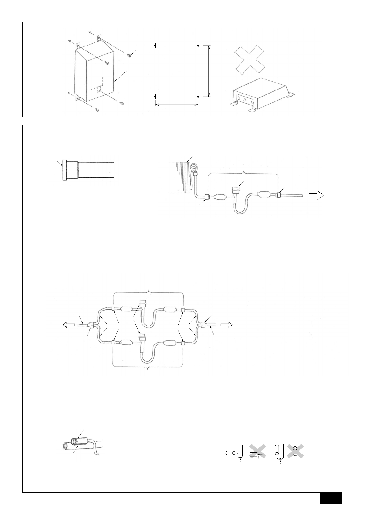
6.2. Liner expansion valve piping work
Attach the supplied LEV-kit to the liquid pipe of the heat exchanger (field supply).
For Type250, connect two LEV-kits.
[Fig. 6.2.1] (P.3)
A Remove the cap
[Fig. 6.2.2] (P.3)
A Heat exchanger (field supply) B LEV-kit
C Brazing D Linear expansion valve
E Outdoor unit
[Fig. 6.2.3] (P.3)
A Heat exchanger (field supply) B LEV-kit
C Brazing D Linear expansion valve
E Outdoor unit
F Refrigerant pipe size ø9.52 (field supply)
G Distributor (field supply)
H Refrigerant pipe size ø9.52 (field supply)
Caution:
Install the LEV-kit inside the AHU, and keep it away from rain or direct sunlight.
Caution:
Install the LEV-kit with its motor upward.
6.3. Thermistor setting work
Caution:
The evaporator and the thermistor must touch each other. The top of the
most sensitive part of the thermistor must touch the evaporator.
[Fig. 6.3.0.1] (P.3)
A Most sensitive point of the thermistor
B Maximize the contact
Caution:
Put the thermistor wire slightly down to avoid water accumulation on top of
the thermistor.
[Fig. 6.3.0.2] (P.3)
9
Page 10

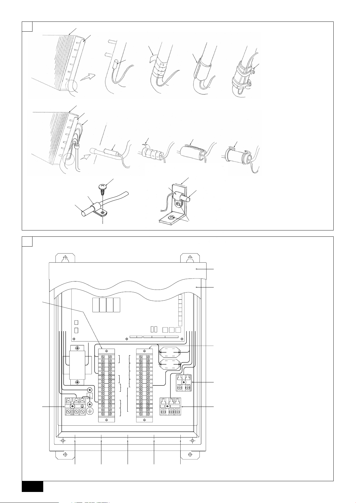
6.3.1 Thermistor for gas pipe
Put the thermistor as close as possible to the branch pipe that is located the closest to the gas pipe (header) connection on the evaporator (field supply).
Turn the lead wire of the thermistor downward, and wind the aluminum tape (field
supply) around the header to fix the thermistor.
Wind the insulation material over it.
Tighten the top and bottom of the insulation material using the supplied tie band.
Fold the lead wire of the thermistor at the bottom, and fix it with the insulation
material using the tie band.
[Fig. 6.3.1] (P.4)
A Heat exchanger (field supply) B Gas pipe
C Thermistor (gas pipe) D Aluminum tape (field supply)
E Insulation F Tie band
GBDFEINLPGRRUTR
7. Electrical wiring
6.3.2 Thermistor for liquid pipe
Put the thermistor on the coldest position to prevent the evaporator from freezing.
Turn the lead wire of the thermistor downward, and wind the aluminum tape (field
supply) around the pipe to fix the thermistor.
Wind the insulation material over it.
Tighten the top and bottom of the insulation material using the supplied tie band.
Fold the lead wire of the thermistor, and fix it with the insulation material using the
tie band.
[Fig. 6.3.2] (P.4)
A Heat exchanger (field supply) B Gas pipe
C Thermistor (liquid pipe) D Aluminum tape (field supply)
E Insulation F Tie band
G Capillary tube
6.3.3 Thermistor for suction/discharge air
Attach the thermistor where the suction/discharge air temperature of the air handling unit can be detected.
[Fig. 6.3.3] (P.4)
A Thermistor (suction/discharge air)
B Clip
C Screw (field supply)
D Plate (field supply)
Precautions on electrical wiring
Warning:
Electrical work should be done by qualified electrical engineers in accordance with “Engineering Standards For Electrical Installation” and supplied
installation manuals. Special circuits should also be used. If the power circuit lacks capacity or has an installation failure, it may cause a risk of electric shock or fire.
1. Be sure to take power from the special branch circuit.
2. Be sure to install an earth leakage breaker to the power.
3. Install the unit to prevent that any of the control circuit cables (remote controller, transmission cables) is brought in direct contact with the power cable outside the unit.
4. Ensure that there is no slack on all wire connections.
5. Some cables (power, remote controller, transmission cables) above the ceiling
may be bitten by mouses. Use as many metal pipes as possible to insert the
cables into them for protection.
6. Never connect the power cable to leads for the transmission cables. Otherwise
the cables would be broken.
7. Be sure to connect control cables to the indoor unit, remote controller, and the
outdoor unit.
8. Put the unit to the ground on the outdoor unit side.
9. Select control cables from the conditions given in page
10
.
Transmission cable specifications
Transmission cables
Type of cable
Cable diameter
Maximum length of transmission lines for centralized
control and indoor/outdoor transmission lines (Maximum
Remarks
The maximum length of the wiring between power
supply unit for transmission lines (on the transmission
lines for centralized control) and each outdoor unit and
CZSVHGPO
*1 Connected with simple remote controller.
Shielding wire (2-core)
CVVS, CPEVS or MVVS
More than 1.25 mm
Max length: 200 m
length via indoor units): 500 m MAX
system controller is 200 m.
2
Caution:
Be sure to put the unit to the ground on the outdoor unit side. Do not connect the earth cable to any gas pipe, water pipe, lightening rod, or telephone
earth cable. Incomplete grounding may cause a risk of electric shock.
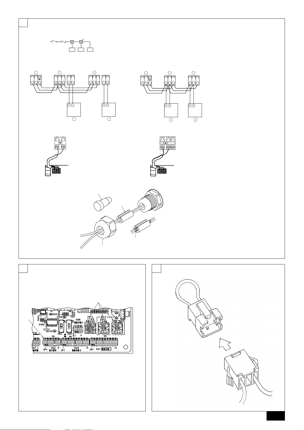
Connecting wiring
[Fig. 7.0.1] (P.4)
A Outer cover B Inner cover
C Ter minal block TB2 D Ter minal block TB5
E Ter minal block TB15 F Ter minal block TBX
G Ter minal block TB4 H Power supply (208 - 240 V)/Ear th
I To outdoor unit J To remote controller
K Distant signal (ON/OFF) L Operation signal
M Error signal N Fan signal
O Defrost signal P Thermistor (gas pipe)
Q Thermistor (liquid pipe) R LEV-kit
S Distant signal T Ther mistor
U Transmission V Thermistor (suction air)
W Thermistor (discharge air)
ME Remote controller cables
Sheathed 2-core cable (unshielded) CVV
0.3 ~ 1.25 mm
When 10 m is exceeded, use cables
with the same specification as
CVVS, MVVS : PVC insulated PVC jacketed shielded control cable
CPEVS : PE insulated PVC jacketed shielded communication cable
CVV : PVC insulated PVC sheathed control cable
2
(0.75 ~ 1.25 mm2)*1
transmission cables.
MA Remote controller cables
0.3 ~ 1.25 mm
2
(0.75 ~ 1.25 mm2)*1
Max length: 200 m
10
Page 11

7.1. Power supply wiring
D1
D2
L1
D11
D12
L2
• Power supply cords of appliances shall not be lighter than design 245 IEC 57
or 227 IEC 57.
• A switch with at least 3 mm contact separation in each pole shall be provided
by the Air conditioner installation.
Power cable size: more than 1.5 mm
[Fig. 7.1.1] (P.5)
A Switch 16 A
B Overcurrent protection 16 A
C Indoor unit
D Total operating current be less than 16 A
E Pull box
[Selecting non-fuse breaker (NF) or earth leakage breaker (NV)]
To select NF or NV instead of a combination of Class B fuse with switch, use the
following:
• In the case of Class B fuse rated 15 A or 20 A,
NF model name (MITSUBISHI): NF30-CS (15 A) (20 A)
NV model name (MITSUBISHI): NV30-CA (15 A) (20 A)
Use an earth leakage breaker with a sensitivity of less than 30 mA 0.1 s.
2
Caution:
Do not use anything other than the correct capacity breaker and fuse. Using
fuse, wire or copper wire with too large capacity may cause a risk of malfunction or fire.
7.2. Connecting remote controller, AHU con-
troller and outdoor transmission cables
(Remote contoroller is optionally available.)
A remote controller is required to perform initial setting. No remote controller is
required after the initial setting, as the unit is controlled on site. Initial setting can
be performed using the M-NET remote controllers connected to other indoor units.
• Connect AHU controller TB5 and outdoor unit TB3. (Non-polarized 2-wire)
The “S” on AHU controller TB5 is a shielding wire connection. For specifications about the connecting cables, refer to the outdoor unit installation manual.
• Install a remote controller following the manual supplied with the remote controller.
• Connect the “1” and “2” on AHU controller TB15 to a MA remote controller.
(Non-polarized 2-wire)
• Connect the “M1” and “M2” on AHU controller TB5 to a M-NET remote control-
ler. (Non-polarized 2-wire)
• Connect the remote controller’s transmission cable within 10 m using a 0.75 mm
core cable. If the distance is more than 10 m, use a 1.25 mm2 junction cable.
[Fig. 7.2.1] (P.5) MA Remote controller
[Fig. 7.2.2] (P.5) M-NET Remote controller
A Terminal block for AHU controller/indoor transmission cable
B Terminal block for outdoor transmission cable
C Remote controller
• DC 9 to 13 V between 1 and 2 (MA remote controller)
• DC 24 to 30 V between M1 and M2 (M-NET remote controller)
[Fig. 7.2.3] (P.5) MA Remote controller
[Fig. 7.2.4] (P.5) M-NET Remote controller
A Non-polarized B Remote Controller
• The MA remote controller and the M-NET remote controller cannot be used at
the same time or interchangeably.
Note:
Ensure that the wiring is not pinched when fitting the terminal box cover.
Pinching the wiring may cut it.
Caution:
Install wiring so that it is not tight and under tension. Wiring under tension
may break, or overheat and burn.
• Fix power source wiring to control box by using buffer bushing for tensile force.
(PG connection or the like.) Connect transmission wiring to transmission terminal block through the knockout hole of control box using ordinary bushing.
• After wiring is complete, make sure again that there is no slack on the connections, and attach the cover onto the control box in the reverse order removal.
Caution:
Wire the power supply so that no tension is imparted. Otherwise disconnection, heating or fire result.
7.3. Connecting LEV-kit and thermistor cables
7.3.1 Connecting LEV-kit cables
Connect the lead wire of the linear expansion valve to the controller.
Pull the end of wire (ring terminal) through the bunch of wires (LEV-kit) at the
bottom of the controller.
Connect the lead wire of the expansion valve to the same colored terminal.
When the lead wire is too long, cut it to the appropriate length. Do not bind it in the
box.
This time, connect the lead wire to the same colored terminal.
7.3.2 Connecting thermistor cables
Pull the end of the wire through the bunch of wires (Thermistor) at the bottom of
the controller.
Connect the thermistor for the discharge air to T1 and T2 on the terminal block, the
thermistor on the gas side to T11 and T12, the thermistor on the liquid side to T21
and T22, the thermistor for the suction air to T31 and T32.
When the lead wire is too long, cut it to the appropriate length. Do not bind it in the
box.
Take proper measures not to miswire. E.g. Attach a label before the cutting part, so
that it is obvious whether the wire is for inlet air, for gas side or for liquid side.
Caution:
Do not route the thermistor cables together with power cables.
7.4. Connecting distant signal line
Pull the wires for operation command (pulse maneuvering), for operation signal
and for error signal through the bunch of wires (Distant signal) at the bottom of the
controller.
Connect each wire to operation command: A1 and A2, to operation signal: D1 and
D2, to error signal: D11 and D12, to fan signal: D21 and D22, and to defrost signal:
D31 and D32.
Item
Operation
2
Operation
signal
Error signal
Fan signal
Connection circuit
■ Operation contact specifications
A1
A2
■ Use a relay when the electrical wire exceeds 10 m.
Relay
power
source
If error resets (stop operation) and restart operations are repeatedly performed, the compressor may be damaged seriously. Install an error lamp, and contact the service firm or the dealer
when an error occurs. Installation of the remote controller is recommended so that the error details can be checked.
D21
D22
A fan control signal is output. It is usually the ON output at the
time of operating, but it is the OFF output in defrosting.
- Be careful to miscarriage lines because over AC200 V is impressed in ON.
- In the case that Dip-switch SW3-4 on the control board is ON,
the fan operates in defrosting also. In this case, be careful of
the cold wind of AHU or to freeze of a humidifier.
- When the switch SWE on the control board is turned on, the
fan signal is always ON.
SW1
Maximum 10 m
A1
A2
Maximum 10 m
X
SW2
SW1: Operation command
(field supply)
Minimum applicable load
DC5 V, 1 mA
X
X: Relay (field supply)
Minimum applicable load
DC5 V, 1 mA
SW2: Operation command
(field supply)
L1: Operation display lamp
(field supply)
Display power source:
DC30 V 1 A, AC100 V/200 V 1 A
L2: Error display lamp
(field supply)
Display power source:
DC30 V 1 A, AC100 V/200 V 1 A
X: Relay (field supply)
X
AC208~240 V 1 A
GBDFEINLPGRRUTRCZSVHGPO
11
Page 12

Defrost signal
Notes:
• After connecting each wire to the terminal, tighten each nut tightly through
which the wire runs.
• Check that the bunch of wires do not come off even if they are pulled
strongly.
D31
D32
A defrost signal is output in defrosting. Be careful to miscarriage
lines because over AC200 V is impressed in ON.
X: Relay (field supply)
X
AC208~240 V 1 A
Caution:
• After the wiring work is completed, mount the inner cover first and then
the outer cover.
• Tighten the screws tightly. (If not, drop of water may enter, leading to
malfunction.)
• Operation signal cables and Error signal cables and Operation command
cables must be routed in a distance of at least 20 cm from all other cables.
• When Operation signal, Error signal and Distant signal are taken out,
remove the plug inside the bunch of wires.
• Wind the supplied tube around the wire according to the size and number
of the wire.
GBDFEINLPGRRUTR
• If the wire comes off the tightly tightened bunch of wires, wind the insulation tape around the wire to make the wire thicker.
[Fig. 7.4.1] (P.5)
A Bunch of wires
B Plug
C Tube
D Insulation tape
7.5. External I/O specifications
Caution:
1. Wiring should be covered by insulation tube with supplementary insulation.
2. Use relays or switches with IEC or equivalent standard.
3. The electric strength between accessible parts and control circuit should
have 2750 V or more.
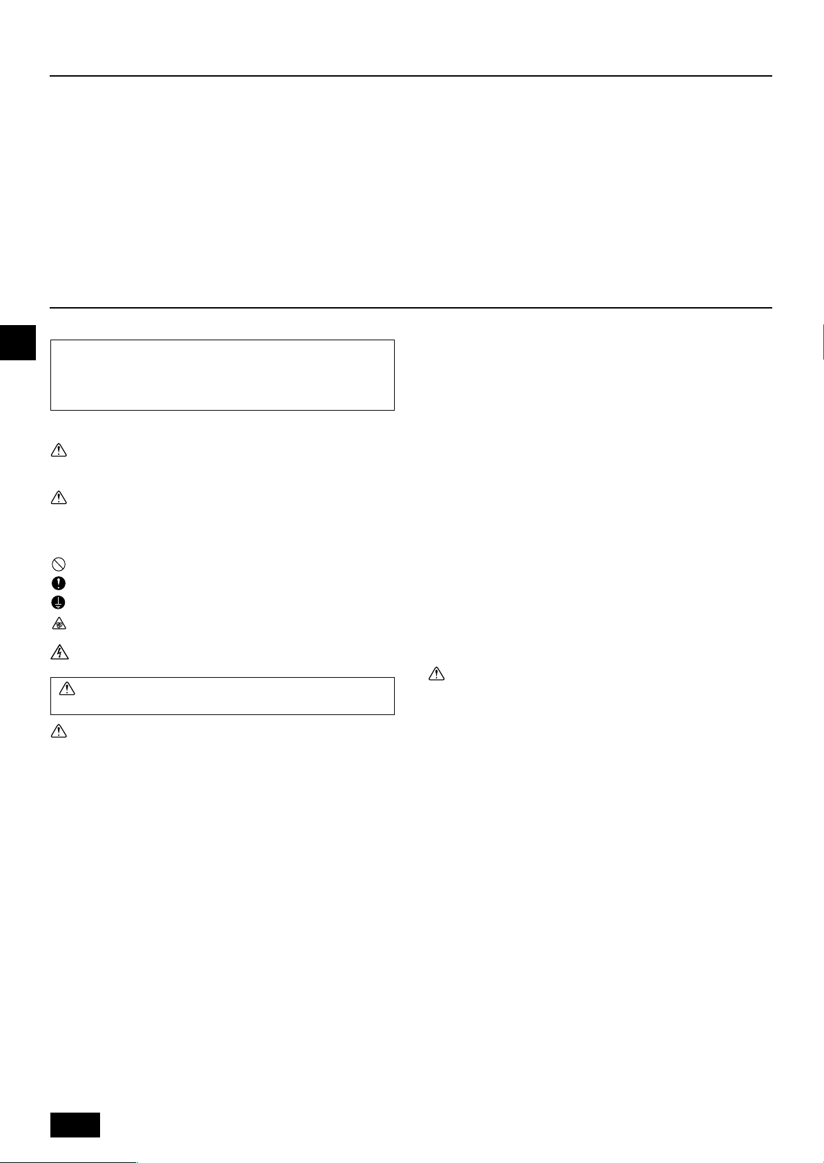
8. Setting switches
8.1. Setting addresses
(Be sure to operate with the main power turned OFF.)
[Fig. 8.1.1] (P.5)
A Address switch B SW2
• There are two types of rotary switch setting available: setting addresses 1 to 9
and over 10, and setting branch numbers.
◆How to set addresses
Example: If Address is “3”, remain SW12 (for over 10) at “0”, and match
SW11 (for 1 to 9) with “3”.
• The rotary switches are all set to “0” when shipped from the factory. These
switches can be used to set unit addresses and branch numbers at will.
• The determination of indoor unit addresses varies with the system at site. Set
them referring to technical data.
8.2. Setting unit capacity
Set the unit capacity according to the heat exchanger type (field supply).
Set the dip switch (SW2) on the control board in accordance with the chart below.
Type
PAC-AH125M-H
PAC-AH140M-H
PAC-AH250M-H
*
indicates ON/OFF state.
Unit capacity
(Air handling unit)
P100
P125
P140
P200
P250
Allowed heat
exchanger capacity
Cooling (heating)
9.0 ~ 11.2 kW
(10.0 ~ 12.5 kW)
11.2 ~ 14.0 kW
(12.5 ~ 16.0 kW)
14.0 ~ 16.0 kW
(16.0 ~ 18.0 kW)
16.0 ~ 22.4 kW
(18.0 ~ 25.0 kW)
22.4 ~ 28.0 kW
(25.0 ~ 31.5 kW)
Setting switches
(SW2)*
123456
ON
OFF
123456
ON
OFF
123456
ON
OFF
123456
ON
OFF
123456
ON
OFF
CZSVHGPO
12
Page 13

8.3. Setting temperature control
1 Thermostat condition in controlling the discharge air temperature
TH21: Discharge air temperature
TH24: Suction air temperature
To: The preset temperature on the remote controller
* The value indicated by boldface in the table below can be changed by a dip-
switch.
<Cooling>
The range of “To”
Thermostat OFF
a) or b) or c)
Thermostat ON
a) & b) & c) & d)
<Heating>
The range of “To”
Thermostat OFF
a) or b) or c)
Thermostat ON
a) & b) & c) & d)
2 Thermostat condition in controlling the suction/return air temperature
TH21: Suction/Return air temperature
TH24: Suction air temperature
To: The preset temperature on the remote controller
* The value indicated by boldface in the table below can be changed by a dip-
switch.
<Cooling>
The range of “To”
Thermostat OFF
a) or b)
Thermostat ON
a) & b) & c)
<Heating>
The range of “To”
Thermostat OFF
14 ~ 30 ˚C
a) TH24 < To
b) TH24 < 14 ˚C
c) TH21 < To – 2 ˚C is continued for 10 minutes.
a) TH24 > To +1 ˚C
b) TH24 > 15 ˚C
c) TH21 > To +1 ˚C
d) It passes from thermostat OFF for 3 minutes.
17 ~ 28 ˚C
a) TH24 > To
b) TH24 > 15 ˚C
c) TH21 > To + 3 ˚C is continued for 10 minutes.
a) TH24 < To –1 ˚C
b) TH24 < 14 ˚C
c) TH21 < To –1 ˚C
d) It passes from thermostat OFF for 3 minutes.
14 ~ 30 ˚C
a) TH24 < 20 ˚C
b) TH21 < To –0.5 ˚C
a) TH24 > 21 ˚C
b) TH21 > To +0.5 ˚C
c) It passes from thermostat OFF for 3 minutes.
17 ~ 28 ˚C
a) TH24 > 21 ˚C
b) TH21 > To
8.4. Dip-switch function
1 Change of discharge or suction air temperature control
Dip switch
SW7-2
OFF
ON
2 TH21
Detection temperature of the thermistor TH21 is replaced to the value below
by Dip switch on the control board.
Dip switch
SW1-2
OFF
ON
OFF
ON
3 TH24
i) Discharge air temperature control
<Cooling>
<Heating>
ii) Suction/return air temperature control
<Cooling>
<Heating>
SW1-3
OFF
OFF
ON
ON
Dip switch
SW3-10
OFF
ON
Dip switch
SW3-8
OFF
ON
Dip switch
SW1-8
OFF
ON
Dip switch
SW3-8
OFF
ON
Thermostat control
Suction / return
Discharge
Detection temperature Remarks
Cooling
TH21
TH21-1
TH21-2
TH21-3
Thermostat condition of TH24 Remarks
Thermo-OFF
14 ˚C
20 ˚C
Thermostat condition of TH24 Remarks
Thermo-OFF
10 ˚C
15 ˚C
Thermostat condition of TH24 Remarks
Thermo-OFF
20 ˚C
15 ˚C
Thermostat condition of TH24 Remarks
Thermo-OFF
10 ˚C
15 ˚C
Heating
TH21
TH21+1
TH21+2
TH21+3
Thermo-ON
15 ˚C
21 ˚C
Thermo-ON
9 ˚C
14 ˚C
Thermo-ON
21 ˚C
16 ˚C
Thermo-ON
9 ˚C
14 ˚C
Remarks
—
Initial setting
Initial setting
—
—
—
Initial setting
—
—
Initial setting
Initial setting
—
—
Initial setting
GBDFEINLPGRRUTRCZSVHGPO
9. Initial setting and test run
After the installation work, which was performed in accordance with the outdoor
unit installation manual, and after the AHU refrigerant piping work, drain piping
work, electrical wiring work, AHU controller wiring work, and switch setting, turn on
the main power at least 12 hours before starting operation in accordance with the
outdoor unit installation manual.
Test run, initial setting
1 Start the fan of AHU.
2 Remove the switch connector inside the controller.
3 Start AHU using the remote controller.
4 Set the operation mode to cooling mode, and set the temperature to 14 °C.
5 Check that cool air blows.
6 Stop AHU using the remote controller.
7 Connect the switch connector as it was.
8 Close the contact A1/A2 (close: ON, open: off)
[Fig. 9.0.1] (P.5)
Notes:
After 16-minute or more cooling operation, and when 1
mistor detection temperature for liquid pipe is detected for 3 minutes in a
row, the linear expansion valve will be closed to prevent freezing. The operation will be normal when either of the following conditions is met.
• When 3 minutes have passed after 10
tion temperature for liquid pipe is detected.
• When 6 minutes have passed after the expansion valve was closed to
prevent freezing.
°C or more of the thermistor detec-
°C or less of the ther-
13
Page 14

Page 15

Page 16

This product is designed and intended for use in the residential, commer-
cial and light-industrial environment.
The product at hand is
based on the following
EU regulations:
• Low Voltage Directive 73/23/EEC
• Electromagnetic Compatibility Directive 89/
336/EEC
Please be sure to put the contact address/telephone number on
this manual before handing it to the customer.
WT04980X02
HEAD OFFICE: TOKYO BLDG., 2-7-3, MARUNOUCHI, CHIYODA-KU, TOKYO 100-8310, JAPAN
Printed in Japan
 Loading...