

Mitsubishi WS-73615, WS-65615A, WS-65615, WS-65515, WS-55615 Owner’s Manual
...
ON SCREEN OPF RAT JIG SYSTEM
TV Information:
Use this space to record the model and serial numbers of your television.
This information is on the back of your TV.
Model number
Serial number
__<_<!i__¸_i_!!_i_illiiii_ _
RISK OF ELECTRIC SHOCK •
DO NOT OPEN
CAUTION: TO REDUCE THE RISK OF ELECTRIC SHOCK, DO NOT REMOVE COVER (OR
BACK). NO USER SERVICEABLE PARTS INSIDE. REFER SERVICING TO QUALIFIED SERVICE
PERSONNEL.
/_The lightning flash with arrowhead symbol within an equilateral triangle is intended to alert the user of
the presence of uninsulated "dangerous voltage" within the product's enclosure that may be sufficient
magnitude to constitute a risk of electric shock.
The exclamation point within an equilateral triangle is intended to alert the user to the presence of important
operating and maintenance (servicing) instructions in the literature accompanying the appliance.
This TV is very heavy! Exercise extreme care when moving TV as foreign material may become
embedded in the castor wheels which could damage wood or other delicate flooring.
Warning: To avoid permanently imprinting a fixed image onto your TV screen, please do not display the same
stationary images on the screen for more than 15% of your total TV viewing in one week. Examples of stationary
images are letterbox top/bottom bars from DVD disc or other video sources, side bars when showing standard
TV pictures on widescreen TVs, stock market reports, video game patterns, black or bright Closed Caption
backgrounds, station Iogos, web sites or stationary computer images. Such patterns can unevenly age the picture
tubes causing permanent damage to the TV. Please see pages 12 and 54 for a detailed explanation.
Note: This equipment has been tested and found to comply with the limits for a Class B digital device, pursuant to
part 15 of the FCC Rules. These limits are designed to provide reasonable protection against harmful interference in
a residential installation. This equipment generates, uses and can radiate radio frequency energy and, if not installed
and used in accordance with the instructions, may cause harmful interference to radio communications. However,
there is no guarantee that interference will not occur in a particular installation. If this equipment does cause harmful
interference to radio or television reception, which can be determined by turning the equipment off and on, the user
is encouraged to try to correct the interference by one or more of the following measures:
• Reorient or relocate the receiving antenna.
• Increase the separation between the equipment and the receiver.
• Connect the equipment into an outlet on a circuit different from that to which the receiver is connected.
• Consult the dealer or an experienced radio/TV technician for help.
Changes or modifications not expressly approved by Mitsubishi could cause harmful interference
and would void the user's authority to operate this equipment.
WARNING: TO REDUCE THE RISK OF FIRE OR ELECTRIC SHOCK, DO NOT EXPOSE THIS APPLIANCE TO RAIN
OR MOISTURE.
CAUTION: TO PREVENT ELECTRIC SHOCK, MATCH WIDE BLADE OF PLUG TO WIDE SLOT, FULLY INSERT.
NOTE TO CATV SYSTEM INSTALLER: THIS REMINDER IS PROVIDED TO CALL THE CATV SYSTEM INSTALLER'S
ATTENTION TO ARTICLE 820-40 OF THE NEC THAT PROVIDES GUIDELINES FOR THE PROPER GROUNDING AND,
IN PARTICULAR, SPECIFIES THAT THE CABLE GROUND SHALL BE CONNECTED TO THE GROUNDING SYSTEM
OF THE BUILDING, AS CLOSE TO THE POINT OF CABLE ENTRY AS PRACTICAL.
Contents
Chapter 1 Television Overview
TV Accessories ..................................................... 8
Special Features ................................................... 8
Front Control Panel ............................................... 9
Back Panel .......................................................... 10
Important Notes ................................................... 12
Chapter 2 Connecting
External Devices
& NetCommand® Setup ...................................... 14
Wall Outlet Cable or Cable Box ........................... 15
Single Analog Antenna ......................................... 16
Separate UHF and VHF Antennas ....................... 16
VCR Video and Audio to an Antenna
or Wall Outlet Cable ............................................. 17
VCR Video and Audio to a Cable Box .................. 18
A/V Receiver or Stereo System .......................... 19
Satellite Receiver or Other Device
with S-Video ......................................................... 19
DVD Player with Component Video .................... 20
DVI Device ............................................................ 20
HDMI Device ........................................................ 21
External DTV Receiver with Component Video ...21
IR Emitter NetCommand@ ................................... 22
IEEE 1394 Devices ............................................... 23
IEEE 1394 Device Connection Styles .................. 24
CableCARD TM Definition and Initial
Screen Display ..................................................... 25
Helpful Hints ......................................................... 26
Chapter 3 NetCommand® Setup and Editing
NetCommand® Pre-Memorized Devices ............ 28
Remote Control Functions: Overview .................. 29
Remote Control Functions: Operation,
Care, Sleep Timer ................................................ 30
NetCommand@ OnScreen Buttons ..................... 31
3D Graphical )_W[0_I Menu System ..................... 32
NetCommand® Initial Setup ................................ 33
Edit NetCommand@
Adding an A/V Receiver ................................. 35
Adding Devices .............................................. 38
Changing, Deleting Devices,
Finish Screen ................................................. 42
Device Selection Menu ........................................ 43
Using the Device Menu Button to
Display Menus ...................................................... 44
Chapter 4 IEEE 1394 Devices and
NetCommand® Controlled Recordings
Adding IEEE 1394 Devices Automatically ............ 46
IEEE 1394 Devices Compatibility ......................... 48
Using the Guide Button to Display
ChannelView TM and Menus .................................. 49
NetCommand@ Controlled Recordings .............. 50
Direct VCR Recording ......................................... 52
NetCommand@ Controlled Peer-to-Peer
Connections ......................................................... 53
Important Notes ................................................... 54
Chapter 5 TV Menu Screen Operations
Main Menu Choices ............................................. 56
Setup Menu .......................................................... 57
NetCommand® Menu .......................................... 59
Antenna Menu ...................................................... 60
Time Menu ........................................................... 62
Captions Menu ..................................................... 63
V-Chip Lock Menu ............................................... 65
Audio Video Menu ................................................ 68
A/V Setting Descriptions ..................................... 69
Chapter 6 Special Features
Display Formats .................................................. 72
Operation of PIP and POP ................................... 74
Device Menu with NetCommand@ ...................... 75
Appendix A: Bypassing the V-Chip Lock ............ 77
Appendix B: High Definition Input
Connection Compatibility .................................... 79
Appendix C: Remote Control
Programming Codes ............................................ 80
Appendix D: On-Screen Information
Displays ................................................................ 83
Appendix E: NetCommand® Specialized
Device Keys ......................................................... 84
Appendix F: Cleaning and Service ...................... 85
Appendix G: Diamond Shield TM Removal ............ 86
Appendix H: Cabinet Separation ........................ 89
Troubleshooting ................................................. 90
Additional Information .......................................... 94
Index ..................................................................... 95
Warranty ............................................................... 97

IM PORTANT SAFEG UAR DS
Please read the following safeguards for your TV and retain for future reference. Always follow all
warnings and instructions marked on the television.
,
Read, Retain and Follow All Instructions
Read all safety and operating instructions before operating the TV. Retain the safety and operating instructions
for future reference. Follow all operating and use instructions.
,
Heed Warnings
Adhere to all warnings on the appliance and in the operating instructions.
,
Cleaning
Unplug the TV from the wall outlet before cleaning. Do not use liquid, abrasive, or aerosol cleaners. Cleaners
can permanently damage the cabinet and screen. Use a lightly dampened cloth for cleaning.
,
Attachments and Equipment
Never add any attachments and/or equipment without approval of the manufacturer as such additions may result
in the risk of fire, electric shock or other personal injury.
,
Water and Moisture
Do not use the TV where contact with or immersion in water is possible. Do not use near bath tubs, wash bowls,
kitchen sinks, laundry tubs, swimming pools, etc.
6. Accessories
Do not place the TV on an unstable cart, stand, tripod or table. The TV may fall, causing
tripod, bracket or table recommended by the manufacturer, or sold with the TV. Any
mounting of the TV should follow the manufacturer's instructions, and should use mounting
accessories recommended by the manufacturer.
serious injury to a child or adult and serious damage to the TV. Use only with a cart, stand,
An appliance and cart combination should be moved with care. Quick stops, excessive force,
and uneven surfaces may cause the appliance and cart combination to overturn.
7. Ventilation
Slots and openings in the cabinet are provided for ventilation and to ensure reliable operation of the TV and to
protect it from overheating. Do not block these openings or allow them to be obstructed by placing the TV on a
bed, sofa, rug, or other similar surface. Nor should it be placed over a radiator or heat register. If the TV is to be
placed in a rack or bookcase, ensure that there is adequate ventilation and that the manufacturer's instructions
have been adhered to.
,
Power Source
This TV should be operated only from the type of power source indicated on the marking label. If you are not sure
of the type of power supplied to your home, consult your appliance dealer or local power company.
g,
Grounding or Polarization
This TV is equipped with a polarized alternating current line plug having one blade wider than the other. This plug
will fit into the power outlet only one way. If you are unable to insert the plug fully into the outlet, try reversing the
plug. If the plug should still fail to fit, contact your electrician to replace your obsolete outlet. Do not defeat the
safety purpose of the polarized plug.
10.
Power-Cord Protection
Power-supply cords should be routed so that they are not likely to be walked on or pinched by items placed
upon or against them, paying particular attention to cords at plugs, convenience receptacles, and the point
where they exit from the TV.
11.
Lightning
For added protection for this TV during a lightning storm, or when it is left unattended and unused for long
period of time, unplug it from the wall outlet and disconnect the antenna or cable system. This will prevent
damage to the TV due to lightning and power-line surges.
4
IMPORTANT SAFEGUARDS, cont'd.
12.
Power Lines
An outside antenna system should not be located in the vicinity of overhead power lines or other electric light or
power circuits, or where it can fall into such power lines or circuits. When installing an outside antenna system,
extreme care should be taken to keep from touching such power lines or circuits as contact with them might be
fatal.
13.
Overloading
Do not overload wall outlets and extension cords as this can result in a risk of fire or electric shock.
14.
Object and Liquid Entry
Never push objects of any kind into this TV through openings as they may touch dangerous voltage points or
short-out parts that could result in fire or electric shock. Never spill liquid of any kind on or into the TV.
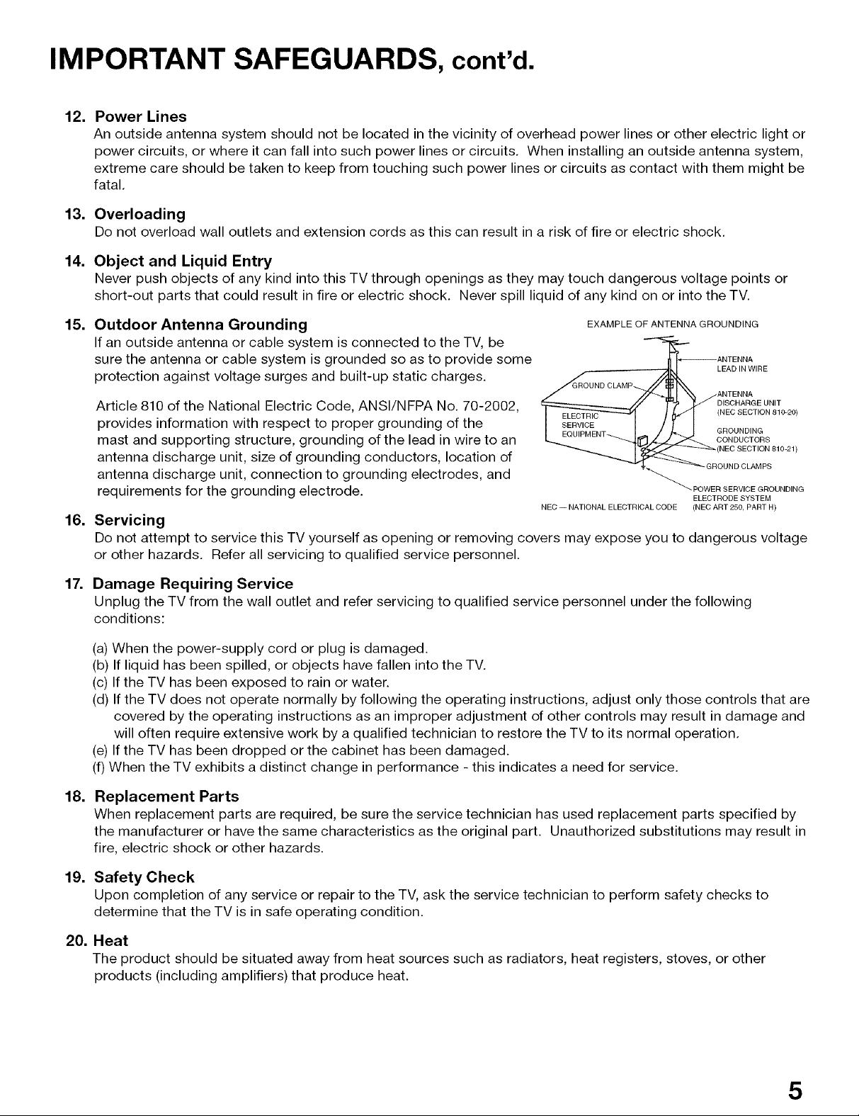
15.
Outdoor Antenna Grounding
EXAMPLE OF ANTENNA GROUNDING
If an outside antenna or cable system is connected to the TV, be
sure the antenna or cable system is grounded so as to provide some
protection against voltage surges and built-up static charges.
Article 810 of the National Electric Code, ANSI/NFPA No. 70-2002,
provides information with respect to proper grounding of the
mast and supporting structure, grounding of the lead in wire to an
antenna discharge unit, size of grounding conductors, location of
antenna discharge unit, connection to grounding electrodes, and
requirements for the grounding electrode.
16.
Servicing
ELECTRIC
SERVICE
NEC -- NATIONAL ELECTRICAL CODE
LEAD IN WIRE
(NEC SECTION 810_20)
GROUNDING
CONDUCTORS
-GROUND CLAMPS
-POWER SERVICE GROUNDING
ELECTRODE SYSTEM
(NEC ART 250, PART H)
Do not attempt to service this TV yourself as opening or removing covers may expose you to dangerous voltage
or other hazards. Refer all servicing to qualified service personnel.
17.
Damage Requiring Service
Unplug the TV from the wall outlet and refer servicing to qualified service personnel under the following
conditions:
(a) When the power-supply cord or plug is damaged.
(b) If liquid has been spilled, or objects have fallen into the TV.
(c) If the TV has been exposed to rain or water.
(d) Ifthe TV does not operate normally by following the operating instructions, adjust only those controls that are
covered by the operating instructions as an improper adjustment of other controls may result in damage and
will often require extensive work by a qualified technician to restore the TV to its normal operation.
(e) If the TV has been dropped or the cabinet has been damaged.
(f) When the TV exhibits a distinct change in performance - this indicates a need for service.
I)
18.
Replacement Parts
When replacement parts are required, be sure the service technician has used replacement parts specified by
the manufacturer or have the same characteristics as the original part. Unauthorized substitutions may result in
fire, electric shock or other hazards.
19.
Safety Check
Upon completion of any service or repair to the TV, ask the service technician to perform safety checks to
determine that the TV is in safe operating condition.
20.
Heat
The product should be situated away from heat sources such as radiators, heat registers, stoves, or other
products (including amplifiers) that produce heat.
5
Our Thanks...
Thank you for choosing Mitsubishi as your premier Home Entertainment provider.
This Owner's Guide describes the features and functions of your Mitsubishi
widescreen, high definition TV. We urge you to examine this Owner's Guide to
become familiar with the innovative features and operations this unique television
offers.
The very core of our corporate philosophy is to provide our customers with the
very best. Our development team at Mitsubishi has worked to provide you with
a television that defines "state-of-the-art," with the capability to meet your needs
now and in the future.
Whether this is your first Mitsubishi electronic product, or an addition to your
Mitsubishi collection, we befieve you and your family will continue to enjoy your
Mitsubishi home theater for many years.
Thank you,
Mitsubishi Digital Electronics America, Inc.
6
TV Accessories ............................................................ ................................. 8
Special Features ............................................................................................ 8
Front Control Panel ....................................................................................... 9
Back Panel .................................................................................................. 10
Important Notes .......................................................................................... 12
TV Accessories
Special Features
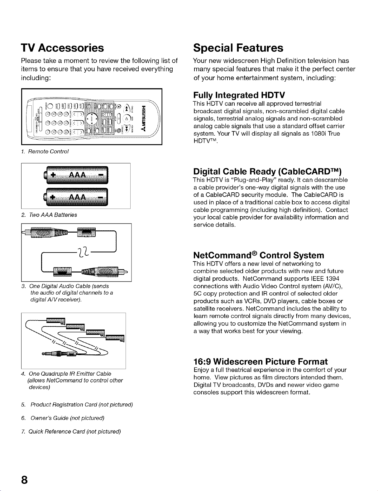
Please take a moment to review the following list of
items to ensure that you have received everything
including:
1. Remote Control
2. Two AAA Batteries
Your new widescreen High Definition television has
many special features that make it the perfect center
of your home entertainment system, including:
Fully Integrated HDTV
This HDTV can receive all approved terrestrial
broadcast digital signals, non-scrambled digital cable
signals, terrestrial analog signals and non-scrambled
analog cable signals that use a standard offset carrier
system. Your TV will display all signals as 1080i True
HDTVTM.
Digital Cable Ready (CableCARD TM)
This HDTV is "Plug-and-Play" ready. It can descramble
a cable provider's one-way digital signals with the use
of a CableCARD security module. The CableCARD is
used in place of a traditional cable box to access digital
cable programming (including high definition). Contact
your local cable provider for availability information and
service details.
3. One Digital Audio Cable (sends
the audio of digital channels to a
digital A/V receiver).
4. One Quadruple IR Emitter Cable
(allows NetCommand to control other
devices)
5. Product Registration Card (not pictured)
6. Owner's Guide (not pictured)
7. Quick Reference Card (not pictured)
NetCommand ® Control System
This HDTV offers a new level of networking to
combine selected older products with new and future
digital products. NetCommand supports IEEE 1394
connections with Audio Video Control system (AV/C),
5C copy protection and IR control of selected older
products such as VCRs, DVD players, cable boxes or
satellite receivers. NetCommand includes the ability to
learn remote control signals directly from many devices,
allowing you to customize the NetCommand system in
a way that works best for your viewing.
16:9 Widescreen Picture Format
Enjoy a full theatrical experience in the comfort of your
home. View pictures as film directors intended them.
Digital TV broadcasts, DVDs and newer video game
consoles support this widescreen format.
8
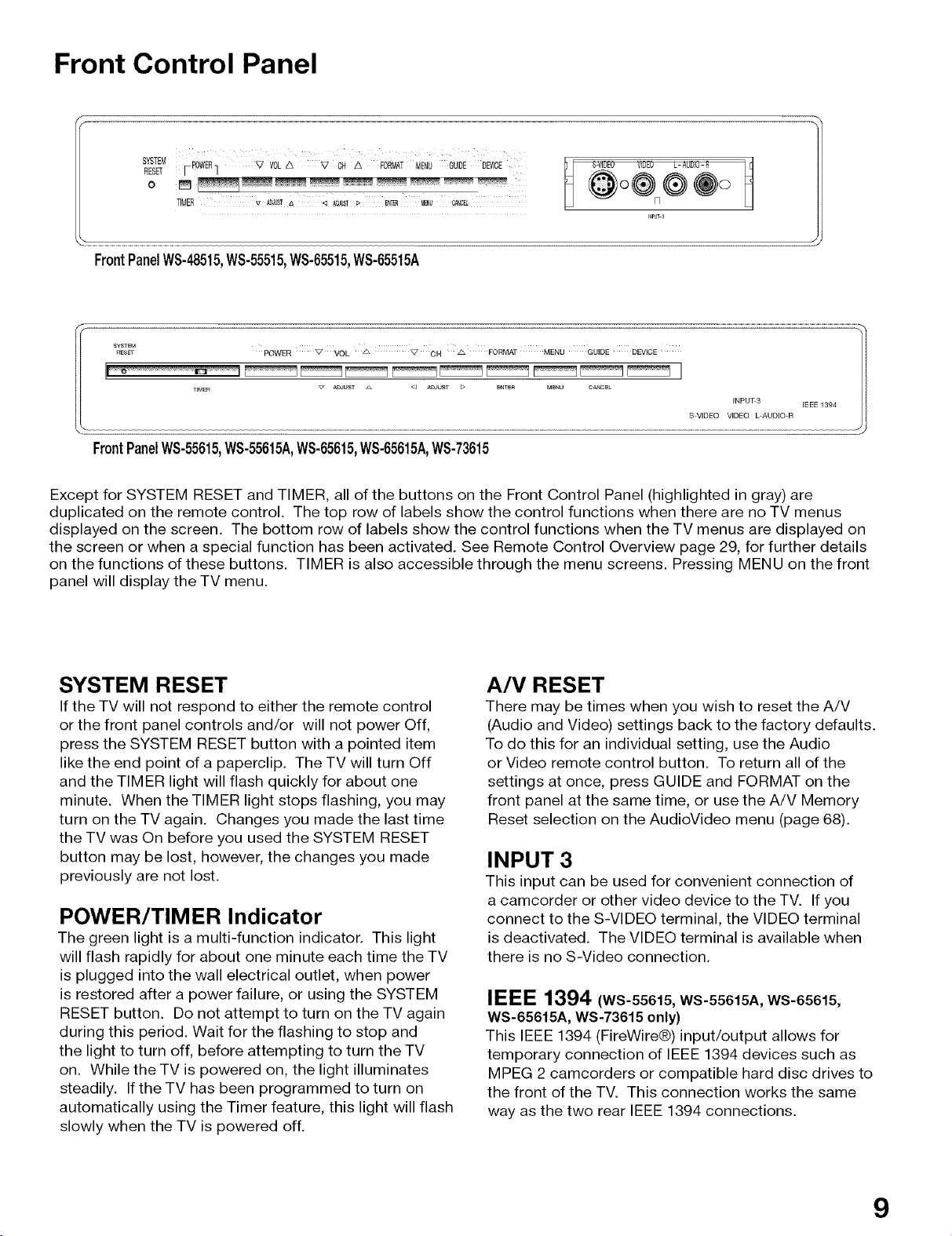
Front Control Panel
SYSTEM r POWER_ V V0L A V ON A FORMAT MENU GUIDE DE_JICE
RESET / /
TIMER v _JUS_A < AOJUST_ Et_ MENU _C_L
FrontPanelWS-48515,WS-55515,WS-65515,WS-65515A
FrontPanelWS-55615,WS-55615A,WS-65615,WS-65615A,WS-73615
Except for SYSTEM RESET and TIMER, all of the buttons on the Front Control Panel (highlighted in gray) are
duplicated on the remote control. The top row of labels show the control functions when there are no TV menus
displayed on the screen. The bottom row of labels show the control functions when the TV menus are displayed on
the screen or when a special function has been activated. See Remote Control Overview page 29, for further details
on the functions of these buttons. TIMER is also accessible through the menu screens. Pressing MENU on the front
panel will display the TV menu.
S-_iDEO JiOEO L-AUDiO-R _
@o®®÷o
INPUT-S
SYSTEM RESET
If the TV will not respond to either the remote control
or the front panel controls and/or will not power Off,
press the SYSTEM RESET button with a pointed item
like the end point of a paperclip. The TV will turn Off
and the TIMER light will flash quickly for about one
minute. When the TIMER light stops flashing, you may
turn on the TV again. Changes you made the last time
the TV was On before you used the SYSTEM RESET
button may be lost, however, the changes you made
previously are not lost.
POWER/TIMER Indicator
The green light is a multi-function indicator. This light
will flash rapidly for about one minute each time the TV
is plugged into the wall electrical outlet, when power
is restored after a power failure, or using the SYSTEM
RESET button. Do not attempt to turn on the TV again
during this period. Wait for the flashing to stop and
the light to turn off, before attempting to turn the TV
on. While the TV is powered on, the light illuminates
steadily. If the TV has been programmed to turn on
automatically using the Timer feature, this light will flash
slowly when the TV is powered off.
A/V RESET
There may be times when you wish to reset the A/V
(Audio and Video) settings back to the factory defaults.
To do this for an individual setting, use the Audio
or Video remote control button. To return all of the
settings at once, press GUIDE and FORMAT on the
front panel at the same time, or use the A/V Memory
Reset selection on the AudioVideo menu (page 68).
INPUT 3
This input can be used for convenient connection of
a camcorder or other video device to the TV. If you
connect to the S-VIDEO terminal, the VIDEO terminal
is deactivated. The VIDEO terminal is available when
there is no S-Video connection.
IEEE 1394 (ws-55015,WS-55615A, WS-65615,
WS-65615A, WS-73615 only)
This IEEE 1394 (FireWire®) input/output allows for
temporary connection of IEEE 1394 devices such as
MPEG 2 camcorders or compatible hard disc drives to
the front of the TV. This connection works the same
way as the two rear IEEE 1394 connections.
9
Back Panel
10. 9.
1_8.
1. 2. 3. 4. 5. 6. 7,
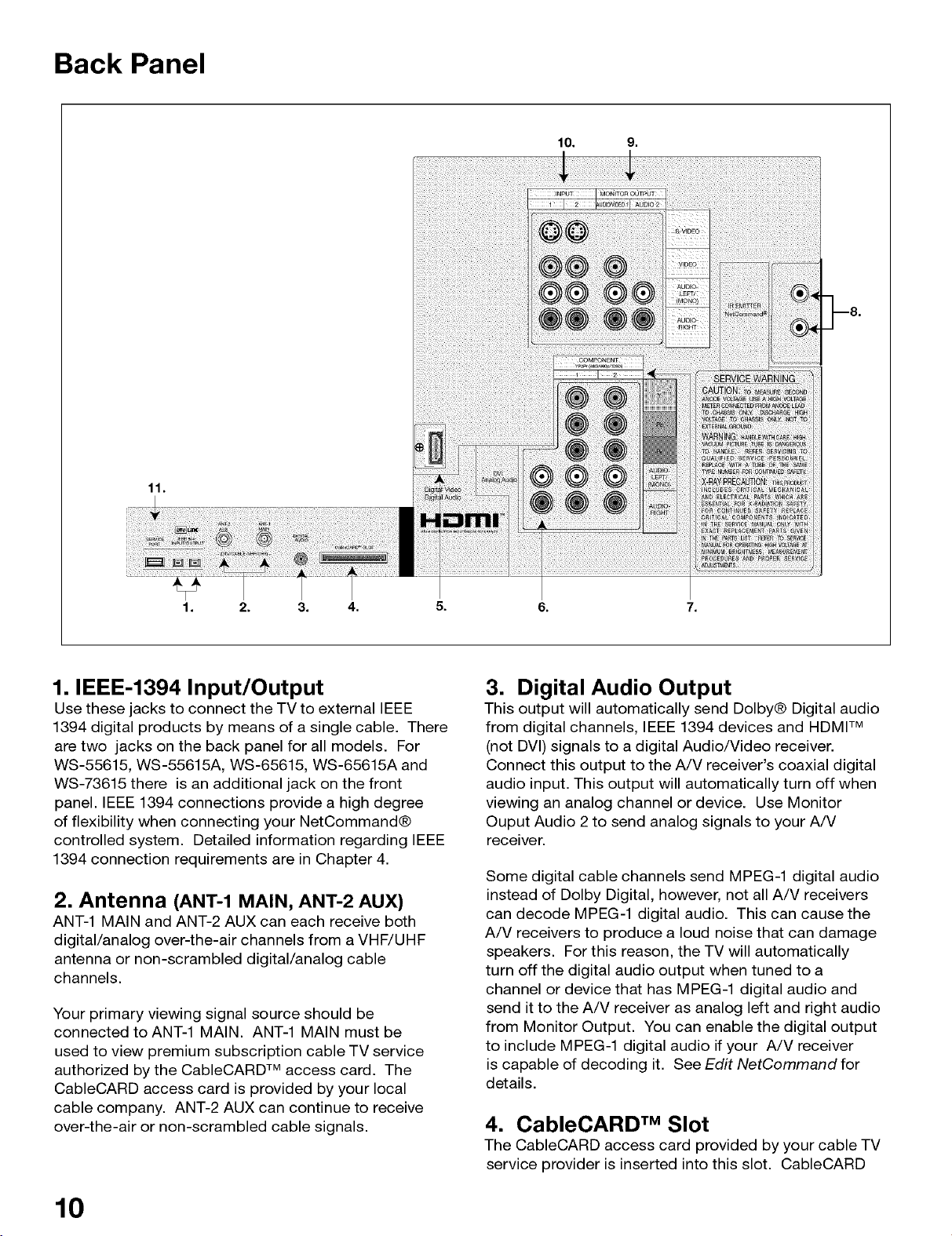
1. IEEE-1394 Input/Output
Use these jacks to connect the TV to external IEEE
1394 digital products by means of a single cable. There
are two jacks on the back panel for all models. For
WS-55615, WS-55615A, WS-65615, WS-65615A and
WS-73615 there is an additional jack on the front
panel. IEEE 1394 connections provide a high degree
of flexibility when connecting your NetCommand®
controlled system. Detailed information regarding IEEE
1394 connection requirements are in Chapter 4.
2. Antenna (ANT-1 MAIN, ANT-2 AUX)
ANT-1 MAIN and ANT-2 AUX can each receive both
digital/analog over-the-air channels from a VHF/UHF
antenna or non-scrambled digital/analog cable
channels.
Your primary viewing signal source should be
connected to ANT-1 MAIN. ANT-1 MAIN must be
used to view premium subscription cable TV service
authorized by the CableCARD TM access card. The
CableCARD access card is provided by your local
cable company. ANT-2 AUX can continue to receive
over-the-air or non-scrambled cable signals.
3. Digital Audio Output
This output will automatically send Dolby® Digital audio
from digital channels, IEEE 1394 devices and HDMI TM
(not DVI) signals to a digital Audio/Video receiver.
Connect this output to the A/V receiver's coaxial digital
audio input. This output will automatically turn off when
viewing an analog channel or device. Use Monitor
Ouput Audio 2 to send analog signals to your A/V
receiver.
Some digital cable channels send MPEG-1 digital audio
instead of Dolby Digital, however, not all A/V receivers
can decode MPEG-1 digital audio. This can cause the
A/V receivers to produce a loud noise that can damage
speakers. For this reason, the TV will automatically
turn off the digital audio output when tuned to a
channel or device that has MPEG-1 digital audio and
send it to the A/V receiver as analog left and right audio
from Monitor Output. You can enable the digital output
to include MPEG-1 digital audio if your A/V receiver
is capable of decoding it. See Edit NetCommand for
details.
4. CableCARD TM Slot
The CableCARD access card provided by your cable TV
service provider is inserted into this slot. CableCARD
10
Back Panel, continued
is a nationwide standard system that allows your local
cable TV provider to supply you with an access card
customized to your account. This card allows the
TV to receive, decode and unscramble the premium
digital channels included in your cable TV subscription
without the use of a cable box. It also allows your
cable provider to automatically update and change your
subscription. See pages 15, 25, and 44 for additional
CableCARD information and activation instructions.
If your cable company is not currently offering
CableCARD, you will need to use an external cable box.
5. HDMF Mor DVI Devices
The HDMI TM interface supports uncompressed
standard, enhanced and high definition digital video
formats. This interface also supports existing digital
multi-channel audio formats. The HDMI input supports
both video and audio using one single cable. Use this
input to connect to EIA/CEA-861 compliant devices
such as a high definition receiver or DVD player. This
input supports the 480i, 480p and 1080i video formats.
It is not intended for use with personal computers
or devices outputting video signals with computer
resolutions.
This input can also be used as a DVI connection
with separate analog audio inputs (see DVI Analog
Audio, below). An optional HDMI-to-DVI adaptor will
be necessary to make this connection and can be
purchased from your local electronics retailer. When
using the optional HDMI-to-DVI adapter, the DVI analog
audio inputs on your TV allow you to receive left and
right audio from your DVI device.
This input is HDCP (High-Bandwidth Digital Copy
Protection) compliant.
8. IR Output-NetCommand ®
Two jacks are provided for connecting IR emitters. IR
Emitters connected to these jacks are used by the
TV's NetCommand system to control external analog
devices such as VCRs, DVDs, cable boxes, satellite
and audio receivers.
9. Monitor Output (Audio/Video 1, Audio 2)
The Monitor Output sends the TV audio and video
signals from the antennas or Inputs 1-3 to an A/V
Receiver or other analog A/V equipment such as a
VCR. Digital channels and IEEE 1394 signals will be
down converted to analog signals compatible with
traditional analog VCRs. There will be no video signals
from digital channels or IEEE 1394 signals that have
copy restrictions. There will be no video signals from
Monitor Outputs when viewing the Component 1 & 2
inputs or the HDMI input
Monitor Output Audio/Video 1 should be connected to
a VCR for recording. Monitor Output Audio 2 should
be connected to your A/V Receiver for home theater
surround sound.
10. Inputs 1-2
These inputs can be used for the connection of a VCR,
Super VHS (S-VHS) VCR, DVD player, standard satellite
receiver or other A/V device to the TV. Please note
that if you connect to the S-VIDEO terminal, the VIDEO
terminal is deactivated. The VIDEO terminal is available
when there is no S-Video connection.
11. SERVICE PORT
This input is for use by Authorized Mitsubishi Servicers
only.
6. DVI Analog Audio
Unlike HDMI, DVI does not carry audio information on
the same cable. Use these analog stereo audio inputs
when using the HDMI input with a device that outputs
DVl instead of HDMI.
7. Component Inputs 1-2
YPbPr(480i/480p/1080i)
These inputs can be used for the connection of devices
with component video outputs, such as a DVD player,
external HDTV receiver or compatible video game
system. Please see Appendix B for signal compatibility.
11
I
IMPORTAN NOTES
Warning: Do not leave stationary PIP/POP, or letterbox images on the screen
for extended periods of time. Mix the types of pictures shown.
Uneven picture tube aging is NOT covered by your warranty.
The normal use of a TV should include a mixture of TV picture types. The most frequently used picture types
should fill the screen with constantly moving images rather than stationary images or patterns. Displaying the same
stationary patterns over extended periods of time or displaying the same stationary pattern frequently can leave
subtle but permanent ghost images. To avoid this, mix your viewing patterns. Reducing the initial contrast level can
help slow the aging process. Do not show the same stationary image for more than 15% of your total TV viewing in
any given week. Display constantly moving and changing images that fill the screen whenever possible.
This projection TV uses picture tubes to project the image to the screen. All picture tubes age with use. As they age,
their light output is gradually reduced. Normal TV pictures fill the screen with constantly changing images. Under
these conditions, picture tubes age at an even rate across the entire screen. This maintains a TV picture that is
evenly bright over the whole screen. Stationary images or images that only partially fill the screen (leaving black
or colored bars to fill the screen), when used over extended periods of time or when viewed repeatedly, can cause
uneven aging of the phosphors and leave subtle ghosts from the stationary images in the picture.
Still or stationary images may be received from broadcasters, cable channels, satellite channels, DVD discs, video
tapes, laser discs, on-line services, web/Internet searching devices, video games, and digital TV tuner/converter
boxes.
I
Examples of these types of images can be, but are not limited to the following:
_q. Letterbox top/bottom black bars:
shown at the top and bottom of the TV screen when you watch a widescreen (16:9) movie on a standard (4:3) TV.
_q. Side bar images:
solid bars shown on each side of an image when watching a standard (4:3) program on a widescreen (16:9) TV.
_. News and stock-market report bars:
ticker running at the bottom of the TV screen.
_. Shopping channel Iogos & pricing displays:
bright graphics that are shown constantly or repeatedly in the same location.
_. Video game patterns and scoreboards
Bright station Iogos:
moving or low-contrast graphics are less likely to cause uneven aging of the picture tubes.
_q. Online (Internet) websites:
or any other stationary or repetitive computer style images, including digital photos or computer applications/
programs.
_I. Closed Captioning
Mitsubishi recommends using a gray background rather than black or a bright color if you frequently use closed
captioning.
12

External Devices & NetCommand® Setup ................................................... 14
DV! Device ........................
HDMI Device .................................................................. 20
• •= • • _ _ •J ,a • ==
.m m......mm.mm.am= • =.m =J'mm='m_m*'mm.am...mm.mm.am.._.m=.m.
External DTV Receiver with Component Video ..... i............................... 21
IR Emitter NetCommand® ..... ".......................................... 21
IEEE 1394 Devices ....... "................................................. 22
IEEE 1394 Device Connection ............................... 23
Helpful Hints Styles ............................................................ 24
CableCARDT_ Definition and Initial Screen Display .................................... 25
==================================================================================================== 26
"•='l•='_'=='ma'J =========================== ,ml.••.m _
-liar=m==,=•, ,, mll•=_,

Connecting External Devices & NetCommand ® Setup
NetCommand is able to control many current audio and video devices by sending remote control signals from the
TV to each device through IR emitters. Additionally, it is able to learn the remote control signals used by most audio
video devices not already in the TV's memory. NetCommand can automatically switch the TV along with compatible
or learned Audio/Video (A/V) Receivers to the correct input for use with each device. It is important that the inputs
on the TV and A/V Receiver back panel match the NetCommand setup that is displayed on-screen.
To simplify the installation of NetCommand, there is a step-by-step on-screen NetCommand setup procedure in this
chapter, which details the type and brand of devices you are connecting to the TV. The NetCommand Setup also
assigns preset TV and A/V Receiver inputs for each device. You should connect each device to the TV input (both
audio and video) and to the A/V Receiver (audio) as shown in the figure below.
Device to be
video and stereo connected stereo and/or digital
audio cables _-.__ _ I audio cables
TV "_ AV
I stereo and digital audio cables I
The following charts show which preset inputs you should use on the TV and A/V Receiver.
Chart 1 shows TV inputs.
Chart 2 shows the A/V Receiver inputs used by A/V Receiver models already known by NetCommand.
Chart 1
Device Audio and Video Outputs to TV Inputs
Cable for CableCARD TM Service ANT-1
Antenna/Cable (digital/analog) ANT-1 if primary viewing source,
ANT-2 if secondary viewing source
Cable box ANT-2
VCR Input-1
Satellite Receiver (DBS) Input-2
Camcorder Input-3 (onfront panel)
DVD Player Component-1
IMit_Hhi_hilIMit_Hhi_hi_lMitsubishi1 Mitsubishi 2 Bose Denon Inte ra Kenwood Marantz Pioneer I Pioneer 2 Rotel Son Yamaha 1 Yamaha 2
Chart 2 _ -_'d'el Model
Lifestyle ®28
Device Audio Output to AV Receiver Inputs by Name
VCR VCR 1 VCR VCR VCR-1 Video 1 Video 1 VCR1 VCR/Ta e VCR 1/DVR Video 2 Video 1 VCR 1 VCR 1
_ D-WILD
Receiver
i Xo pi TVlTV I TV CBL/SAT
After using NetCommand Setup, you may go to the NetCommand menu (see "Edit NetCommand") at any time
to change the inputs you used for connecting each device, custom name devices, add devices not included in
the presets above or delete devices no longer used. See Connection Helpful Hints, at the end of this chapter for
additional information on device setup.
14
Connecting a Wall Outlet Cable or Cable Box
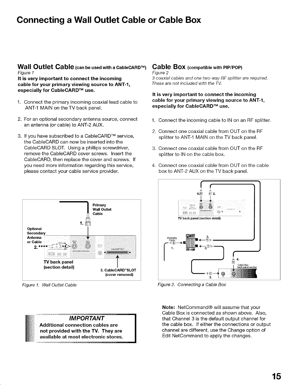
Wall Outlet Cable (can be used with a CableCARDTM)
Figure 1
It is very important to connect the incoming
cable for your primary viewing source to ANT-l,
especially for CableCARD TM use.
1. Connect the primary incoming coaxial lead cable to
ANT-1 MAIN on the TV back panel.
2. For an optional secondary antenna source, connect
an antenna (or cable) to ANT-2 AUX.
3. If you have subscribed to a CableCARD TM service,
the CableCARD can now be inserted into the
CableCARD SLOT. Using a phillips screwdriver,
remove the CableCARD cover screws. Insert the
CableCARD, then replace the cover and screws. If
you need more information regarding this service,
please contact your cable service provider.
Wall Outlet
Cable
_ Primary
1.
Cable Box (compatible with PIP/POP)
Figure 2
3 coaxial cables and one two-way RF splitter are required.
These are not included with the TV.
It is very important to connect the incoming
cable for your primary viewing source to ANT-l,
especially for CableCARD TM use.
1. Connect the incoming cable to IN on an RF splitter.
2. Connect one coaxial cable from OUT on the RF
splitter to ANT-1 MAIN on the TV back panel.
3. Connect one coaxial cable from OUT on the RF
splitter to IN on the cable box.
4. Connect one coaxial cable from OUT on the cable
box to ANT-2 AUX on the TV back panel.
f f
2.
/ /
TV back panel (section detail)
(section detail)
Figure 1. Wall Outlet Cable
i!
IMPORTANT
Additional connection cables are
not provided with the TV. They are
available at most electronic stores,
3. CableCARD_SLOT
(cover removed)
Incoming
Cable
1.
f
Cable Box
3.
Figure 2. Connecting a CableBox
Note: NetCommand® will assume that your
Cable Box is connected as shown above. Also,
that Channel 3 is the default output channel for
the cable box. If either the connections or output
channel are different, use the Change option of
Edit NetCommand to apply the changes.
15
Connecting a Single Analog Antenna or Separate UHF and
VHF Antennas
'_'-'olngle Antenna (notfor usewith CableCARDTM)
Figure 3
A 300-Ohm to 75-Ohm transformer is required. Thisis not
included with the TV.
For antennas with twin flat lead
1. For antenna with twin flat leads, connect the
300-Ohm twin leads to the 300-Ohm to 75-Ohm
transformer.
2. Push the 75-Ohm side of the transformer onto ANT-1
MAIN on the TV back panel.
For antennas with coaxial lead
3. Connect the coaxial lead directly to ANT-1 MAIN on
the TV back panel.
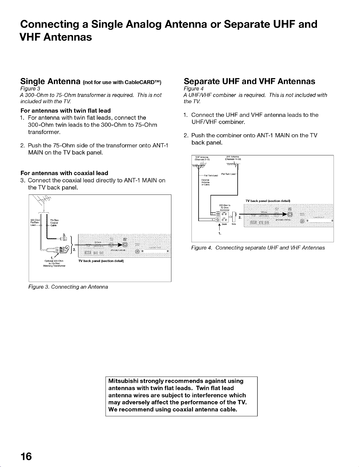
Separate UHF and VHF Antennas
Figure 4
A UHF/VHF combiner is required. Thisis not included with
the TV.
1. Connect the UHF and VHF antenna leads to the
UHF/VHF combiner.
2. Push the combiner onto ANT-1 MAIN on the TV
back panel.
VHFAnte_a UHFAnte_a
(Ch_ne_ 213) (Channels1_-6e)
n_T
F_ TwinLead
EXt0m_
An_nn_
orCable
TV back panel (section detail)
Comb_r
t B_ S_e
1.
Figure 4. Connecting separate UHF and VHF Antennas
W back panel (section detail)
Figure 3. Connecting an Antenna
Mitsubishi strongly recommends against using
antennas with twin flat leads. Twin flat lead
antenna wires are subject to interference which
may adversely affect the performance of the TV.
We recommend using coaxial antenna cable.
16
Connecting VCR Video and Audio to an Antenna or Wall Outlet
Cable
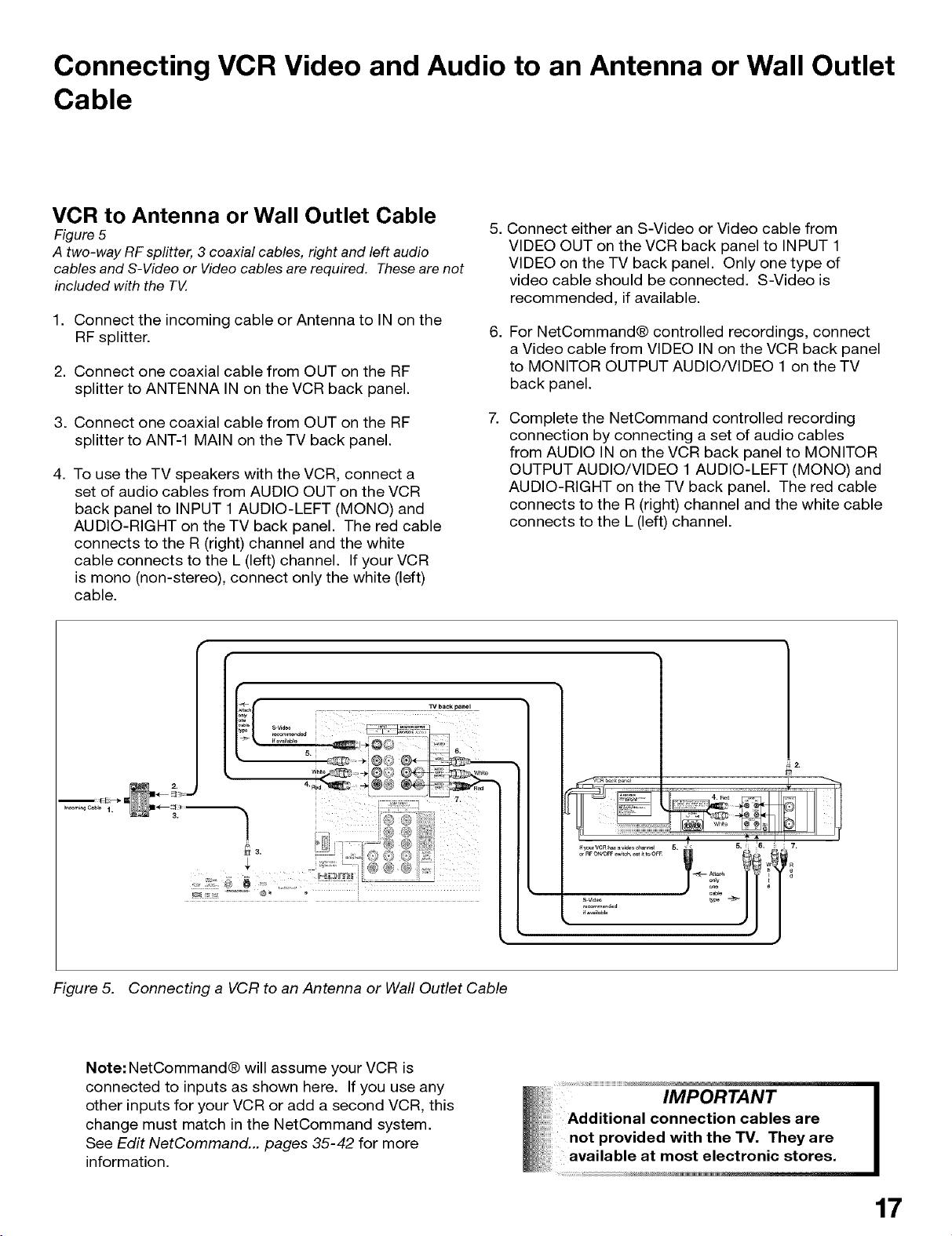
VCR to Antenna or Wall Outlet Cable
Figure 5
A two-way RFsplitter, 3 coaxial cables, right and left audio
cables and S-Video or Videocables are required. Thesearenot
included with the TV.
1. Connect the incoming cable or Antenna to IN on the
RF splitter.
2. Connect one coaxial cable from OUT on the RF
splitter to ANTENNA IN on the VCR back panel.
3. Connect one coaxial cable from OUT on the RF
splitter to ANT-1 MAIN on the TV back panel.
4. To use the TV speakers with the VCR, connect a
set of audio cables from AUDIO OUT on the VCR
back panel to INPUT 1 AUDIO-LEFT (MONO) and
AUDIO-RIGHT on the TV back panel. The red cable
connects to the R (right) channel and the white
cable connects to the L (left) channel. If your VCR
is mono (non-stereo), connect only the white (left)
cable.
5. Connect either an S-Video or Video cable from
VIDEO OUT on the VCR back panel to INPUT 1
VIDEO on the TV back panel. Only one type of
video cable should be connected. S-Video is
recommended, if available.
.
For NetCommand® controlled recordings, connect
a Video cable from VIDEO IN on the VCR back panel
to MONITOR OUTPUT AUDIO/VIDEO 1 on the TV
back panel.
Complete the NetCommand controlled recording
connection by connecting a set of audio cables
from AUDIO IN on the VCR back panel to MONITOR
OUTPUT AUDIO/VIDEO 1 AUDIO-LEFT (MONO) and
AUDIO-RIGHT on the TV back panel. The red cable
connects to the R (right) channel and the white cable
connects to the L (left) channel.
TV backpanel
4 _ _Ps
I
Figure 5. Connecting a VCR to an Antenna or Wall Outlet Cable
Note: NetCommand® will assume your VCR is
connected to inputs as shown here. If you use any
other inputs for your VCR or add a second VCR, this
change must match in the NetCommand system.
See Edit NetCommand... pages 35-42 for more
information.
2,
IMPORTANT
Additional connection cables are
not provided with the TV. They are
available at most electronic stores.
17
Connecting VCR Video and Audio to a Cable Box
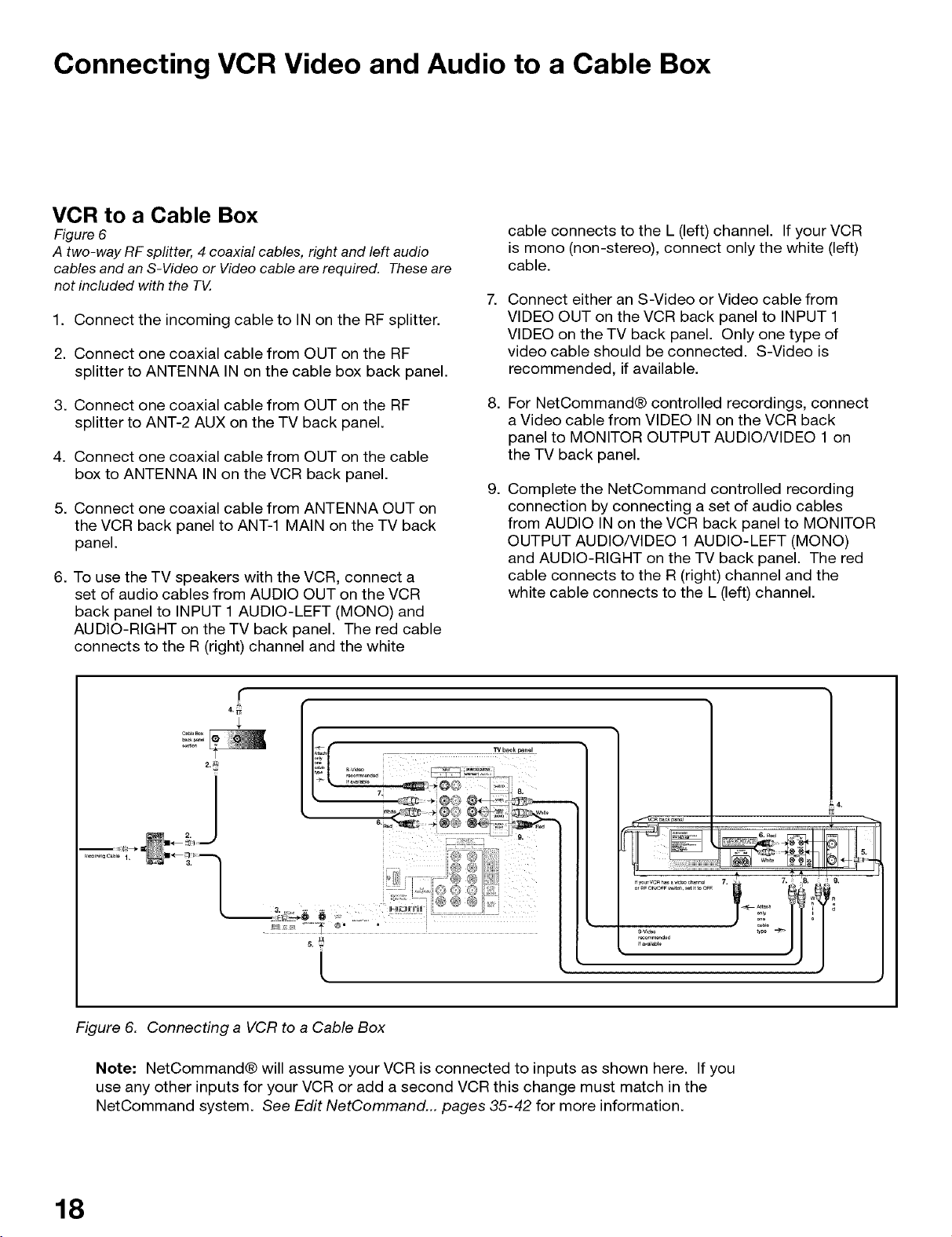
VCR to a Cable Box
Figure 6
A two-way RFsplitter, 4 coaxial cables, right and left audio
cables and an S-Video or Video cable arerequired. These are
not included with the TV.
1. Connect the incoming cable to IN on the RF splitter•
2. Connect one coaxial cable from OUT on the RF
splitter to ANTENNA IN on the cable box back panel•
cable connects to the L (left) channel• If your VCR
is mono (non-stereo), connect only the white (left)
cable•
7• Connect either an S-Video or Video cable from
VIDEO OUT on the VCR back panel to INPUT 1
VIDEO on the TV back panel• Only one type of
video cable should be connected• S-Video is
recommended, if available•
3. Connect one coaxial cable from OUT on the RF
splitter to ANT-2 AUX on the TV back panel•
4. Connect one coaxial cable from OUT on the cable
box to ANTENNA IN on the VCR back panel•
5. Connect one coaxial cable from ANTENNA OUT on
the VCR back panel to ANT-1 MAIN on the TV back
panel•
6. To use the TV speakers with the VCR, connect a
set of audio cables from AUDIO OUT on the VCR
back panel to INPUT 1 AUDIO-LEFT (MONO) and
AUDIO-RIGHT on the TV back panel• The red cable
connects to the R (right) channel and the white
•
For NetCommand® controlled recordings, connect
a Video cable from VIDEO IN on the VCR back
panel to MONITOR OUTPUT AUDIO/VIDEO 1 on
the TV back panel•
•
Complete the NetCommand controlled recording
connection by connecting a set of audio cables
from AUDIO IN on the VCR back panel to MONITOR
OUTPUT AUDIO/VIDEO 1 AUDIO-LEFT (MONO)
and AUDIO-RIGHT on the TV back panel• The red
cable connects to the R (right) channel and the
white cable connects to the L (left) channel•
F .................................................................
IIfvourVCRh d h I _ 7 " =T8 I I g
/
L
Figure 6. Connecting a VCR to a Cable Box
Note: NetCommand® will assume your VCR is connected to inputs as shown here. If you
use any other inputs for your VCR or add a second VCR this change must match in the
NetCommand system• See Edit NetCommand... pages 35-42 for more information•
18
Connecting an A/V Receiver or Stereo System or
a Satellite Receiver or Other Device with S-Video
A/V Receiver or Stereo System
Figure 7
A digital audio cable and stereo audio cables arerequired. The
digital audio cable isprovided. Thestereo audio cables are not
included with the TV.
1. Connect a set of stereo audio cables from OUTPUT
AUDIO 2 on the TV back panel to the TV AUDIO
INPUT on the back of the A/V Receiver. The red
cable connects to the R (right) channel and the
white cable connects to the L (left) channel.
To connect a digital A/V Receiver with Dolby®
Digital surround sound:
2. Connect one end of the digital audio cable supplied
with the TV to DIGITAL AUDIO on the back of the
TV. Connect the other end to the COAXIAL DIGITAL
INPUT on the back of the A/V Receiver.
Check A/V Receiver's Owner's Guide for information
concerning the use of the digital input and switching
between the digital sound and analog stereo sound
from the TV.
TV back panel
i
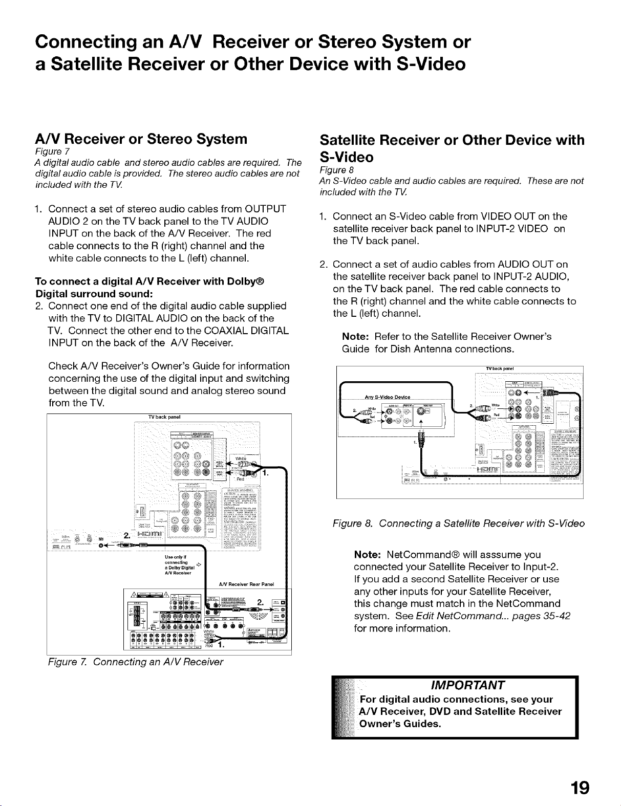
Satellite Receiver or Other Device with
S-Video
Figure 8
An S-Video cable and audio cables are required. Theseare not
included with the TV.
1. Connect an S-Video cable from VIDEO OUT on the
satellite receiver back panel to INPUT-2 VIDEO on
the TV back panel.
2. Connect a set of audio cables from AUDIO OUT on
the satellite receiver back panel to INPUT-2 AUDIO,
on the TV back panel. The red cable connects to
the R (right) channel and the white cable connects to
the L (left) channel.
Note: Refer to the Satellite Receiver Owner's
Guide for Dish Antenna connections.
TV back panel
H +++++,,+ +_+ ++
"W +: t++_++_'+++
I p++ '+y+®® M+++
I ++/,++',+'++@+ _+_:++_+J
+ +L+ + _+++++++® ® ® ++++
+++++'_2 _+ + •.......................+....................................• + ..... +
+++ M+++ ............ @ ' =_'+'_' `+u +.....
Useon_if
connecUng
a DolbyDigital _>
A_/Receiver
Figure 7. Connecting an A/V Receiver
A/V Receiver Rear Panel
Figure 8. Connecting a Satellite Receiver with S-Video
Note: NetCommand® will asssume you
connected your Satellite Receiver to Input-2.
If you add a second Satellite Receiver or use
any other inputs for your Satellite Receiver,
this change must match in the NetCommand
system. See Edit NetCommand... pages 35-42
for more information.
19
Connecting a DVD Player with Component Video or
DVI Device
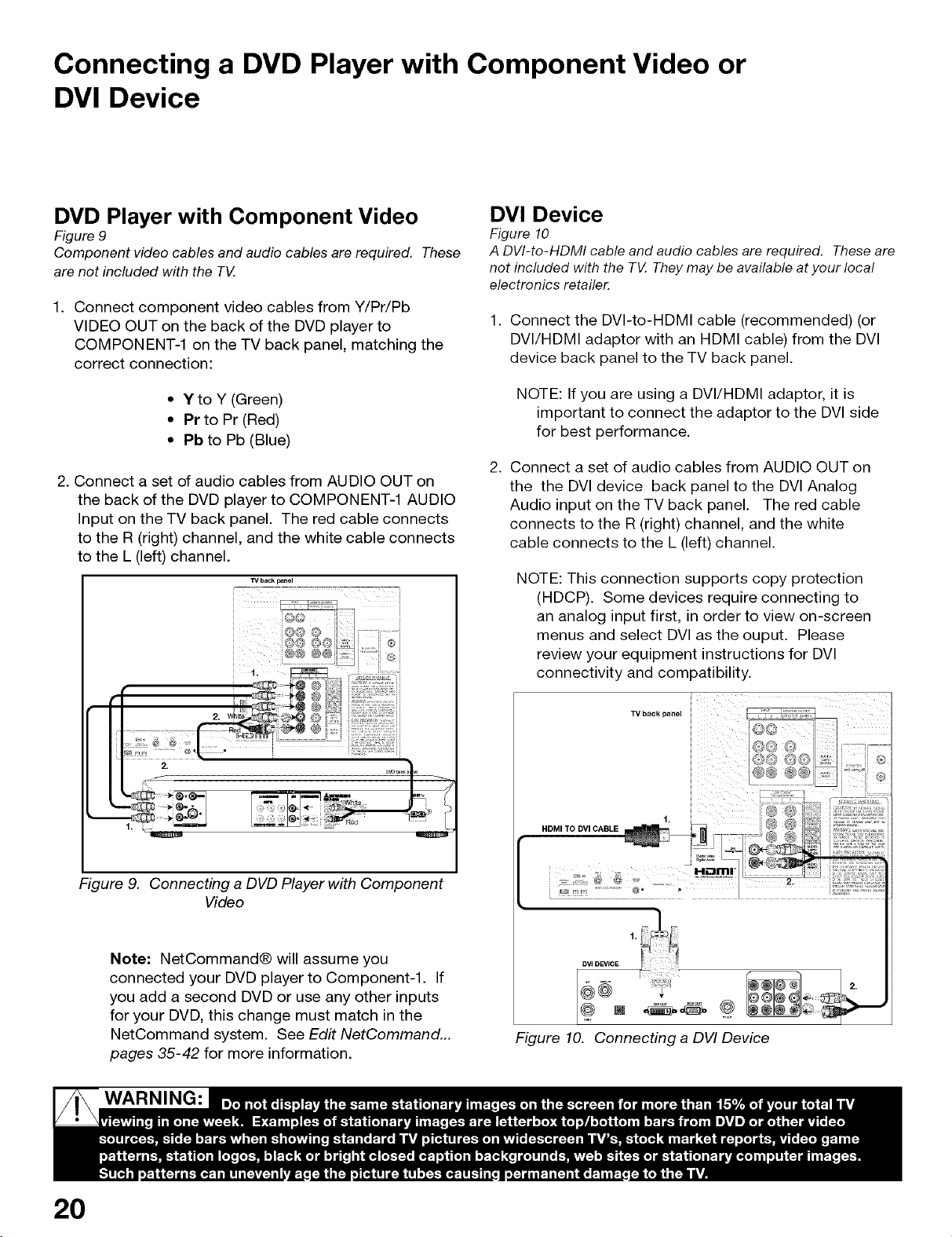
DVD Player with Component Video
Figure 9
Component video cables and audio cables are required. These
are not included with the TV.
1. Connect component video cables from Y/Pr/Pb
VIDEO OUT on the back of the DVD player to
COMPONENT-1 on the TV back panel, matching the
correct connection:
• Y to Y (Green)
• Pr to Pr (Red)
• Pb to Pb (Blue)
2. Connect a set of audio cables from AUDIO OUT on
the back of the DVD player to COMPONENT-1 AUDIO
Input on the TV back panel. The red cable connects
to the R (right) channel, and the white cable connects
to the L (left) channel.
TV back panel
_- 7 7--:_ 7 = = = = 777: 777]
i
i i®i
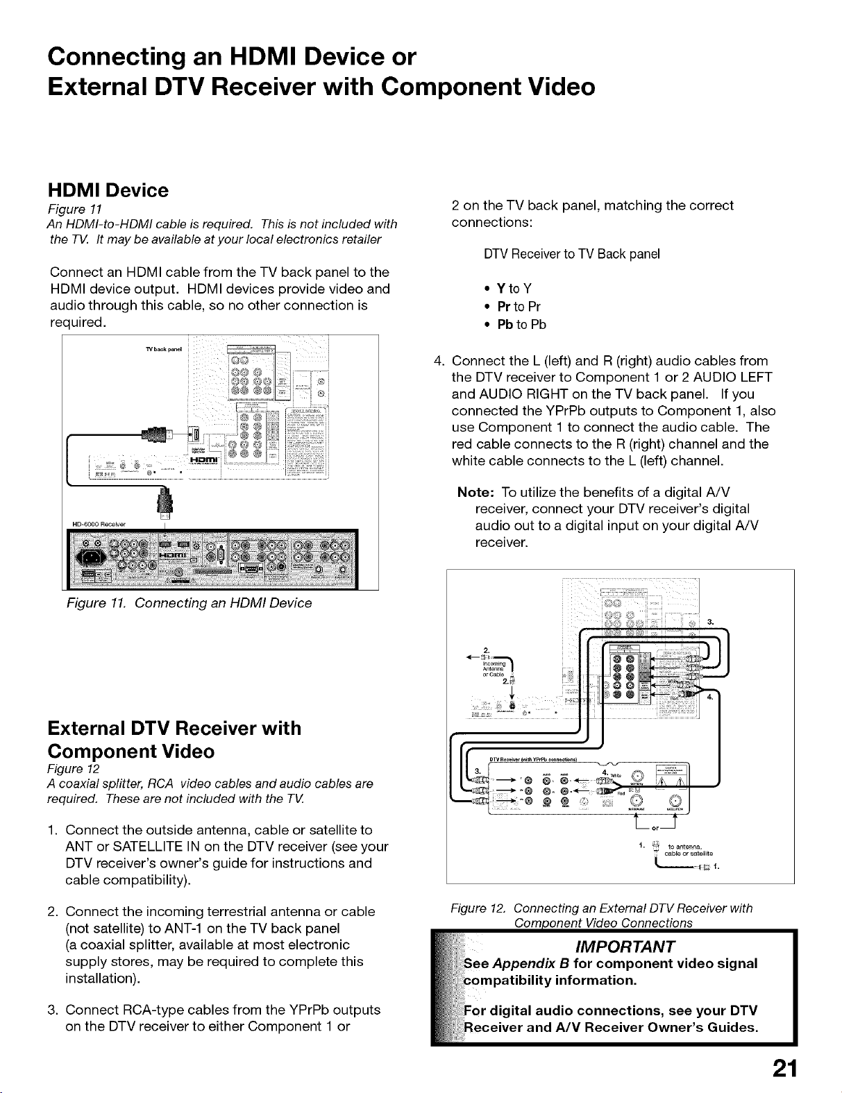
DVI Device
Figure 10
A DVI-to-HDMI cable and audio cables are required. Theseare
not included with the TV.Theymay be available at your local
electronics retailer.
1. Connect the DVI-to-HDMI cable (recommended) (or
DVI/HDMI adaptor with an HDMI cable) from the DVI
device back panel to the TV back panel.
NOTE: If you are using a DVI/HDMI adaptor, it is
important to connect the adaptor to the DVI side
for best performance.
2. Connect a set of audio cables from AUDIO OUT on
the the DVI device back panel to the DVI Analog
Audio input on the TV back panel. The red cable
connects to the R (right) channel, and the white
cable connects to the L (left) channel.
NOTE: This connection supports copy protection
(HDCP}. Some devices require connecting to
an analog input first, in order to view on-screen
menus and select DVI as the ouput. Please
review your equipment instructions for DVI
connectivity and compatibility.
2.
Figure 9. Connecting a DVD Player with Component
Video
Note: NetCommand® will assume you
connected your DVD player to Component-l. If
you add a second DVD or use any other inputs
for your DVD, this change must match in the
NetCommand system. See Edit NetCommand...
pages 35-42 for more information.
WARNING:
TV back Dane _/,
H£3111F
Figure 10. Connecting a DVI Device
20
Connecting an HDMI Device or
External DTV Receiver with Component Video
HDMI Device
Figure 11
An HDMI-to-HDMI cable is required. This isnot included with
the TV. It may be availableat your local electronics retailer
Connect an HDMI cable from the TV back panel to the
HDMI device output. HDMI devices provide video and
audio through this cable, so no other connection is
rec uired.
i
_/baok panel i _/ i i
i i
2 on the TV back panel, matching the correct
connections:
DTVReceiverto TV Back panel
• YtoY
• Prto Pr
• Pbto Pb
4. Connect the L (left) and R (right) audio cables from
the DTV receiver to Component 1 or 2 AUDIO LEFT
and AUDIO RIGHT on the TV back panel. If you
connected the YPrPb outputs to Component 1, also
use Component 1 to connect the audio cable. The
red cable connects to the R (right) channel and the
white cable connects to the L (left) channel.
HD=6000 Receiver
#, o- =..
Figure 11. Connecting an HDMI Device
External DTV Receiver with
Component Video
Figure 12
A coaxial splitter, RCA video cables and audio cables are
required. These are not included with the TV.
1. Connect the outside antenna, cable or satellite to
ANT or SATELLITE IN on the DTV receiver (see your
DTV receiver's owner's guide for instructions and
cable compatibility).
Note: To utilize the benefits of a digital A/V
receiver, connect your DTV receiver's digital
audio out to a digital input on your digital A/V
receiver.
t.
to antenna,
cable or satellit e
t.
2. Connect the incoming terrestrial antenna or cable
(not satellite) to ANT-1 on the TV back panel
(a coaxial splitter, available at most electronic
supply stores, may be required to complete this
installation).
3. Connect RCA-type cables from the YPrPb outputs
on the DTV receiver to either Component 1 or
Figure 12. Connecting an External DTV Receiver with
Video Connections
21
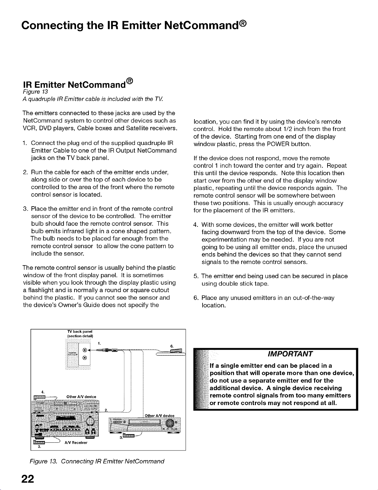
Connecting the IR Emitter NetCommand ®
IR Emitter NetCommand ®
Figure 13
A quadruple IR Emitter cable is included with the TV.
The emitters connected to these jacks are used by the
NetCommand system to control other devices such as
VCR, DVD players, Cable boxes and Satellite receivers.
1. Connect the plug end of the supplied quadruple IR
Emitter Cable to one of the IR Output NetCommand
jacks on the TV back panel.
2. Run the cable for each of the emitter ends under,
along side or over the top of each device to be
controlled to the area of the front where the remote
control sensor is located.
3. Place the emitter end in front of the remote control
sensor of the device to be controlled. The emitter
bulb should face the remote control sensor. This
bulb emits infrared light in a cone shaped pattern.
The bulb needs to be placed far enough from the
remote control sensor to allow the cone pattern to
include the sensor.
The remote control sensor is usually behind the plastic
window of the front display panel. It is sometimes
visible when you look through the display plastic using
a flashlight and is normally a round or square cutout
behind the plastic. If you cannot see the sensor and
the device's Owner's Guide does not specify the
location, you can find it by using the device's remote
control. Hold the remote about 1/2 inch from the front
of the device. Starting from one end of the display
window plastic, press the POWER button.
If the device does not respond, move the remote
control 1 inch toward the center and try again. Repeat
this until the device responds. Note this location then
start over from the other end of the display window
plastic, repeating until the device responds again. The
remote control sensor will be somewhere between
these two positions. This is usually enough accuracy
for the placement of the IR emitters.
.
With some devices, the emitter will work better
facing downward from the top of the device. Some
experimentation may be needed. If you are not
going to be using all emitter ends, place the unused
ends behind the devices so that they cannot send
signals to the remote control sensors.
5. The emitter end being used can be secured in place
using double stick tape.
6. Place any unused emitters in an out-of-the-way
location.
TV back panel
(section detail)
1.
4.
3.
Other ANdevice
AN Receiver
Figure 13. Connecting IR Emitter NetCommand
22
6.
IMPORTANT
If a single emitter end can be placed in a
that will operate more than one device,
do not use a separate emitter end for the
additional device. A single device receiving
control signals from too many emitters
or remote controls may not respond at all.
Other ANdevice
Connecting IEEE 1394 Devices
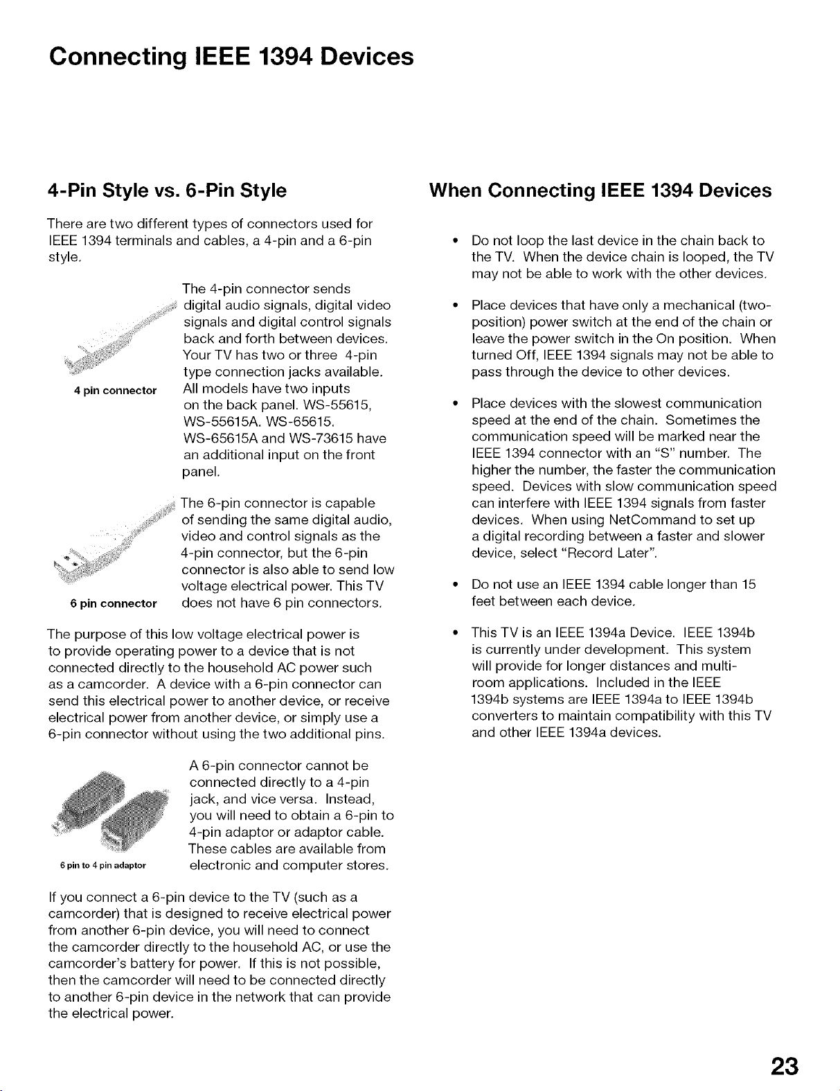
4-Pin Style vs. 6-Pin Style
There are two different types of connectors used for
IEEE 1394 terminals and cables, a 4-pin and a 6-pin
style.
The 4-pin connector sends
digital audio signals, digital video
signals and digital control signals
back and forth between devices.
Your TV has two or three 4-pin
type connection jacks available.
All models have two inputs
on the back panel. WS-55615,
WS-55615A. WS-65615.
WS-65615A and WS-73615 have
an additional input on the front
panel.
The 6-pin connector is capable
of sending the same digital audio,
video and control signals as the
4-pin connector, but the 6-pin
connector is also able to send low
voltage electrical power. This TV
6 pin connector
does not have 6 pin connectors.
When Connecting IEEE 1394 Devices
Do not loop the last device in the chain back to
the TV. When the device chain is looped, the TV
may not be able to work with the other devices.
Place devices that have only a mechanical (two-
position) power switch at the end of the chain or
leave the power switch in the On position. When
turned Off, IEEE 1394 signals may not be able to
pass through the device to other devices.
Place devices with the slowest communication
speed at the end of the chain. Sometimes the
communication speed will be marked near the
IEEE 1394 connector with an "S" number. The
higher the number, the faster the communication
speed. Devices with slow communication speed
can interfere with IEEE 1394 signals from faster
devices. When using NetCommand to set up
a digital recording between a faster and slower
device, select "Record Later".
Do not use an IEEE 1394 cable longer than 15
feet between each device.
The purpose of this low voltage electrical power is
to provide operating power to a device that is not
connected directly to the household AC power such
as a camcorder. A device with a 6-pin connector can
send this electrical power to another device, or receive
electrical power from another device, or simply use a
6-pin connector without using the two additional pins.
A 6-pin connector cannot be
connected directly to a 4-pin
jack, and vice versa. Instead,
you will need to obtain a 6-pin to
4-pin adaptor or adaptor cable.
These cables are available from
6 pin to 4 pin adaptor
If you connect a 6-pin device to the TV (such as a
camcorder) that is designed to receive electrical power
from another 6-pin device, you will need to connect
the camcorder directly to the household AC, or use the
camcorder's battery for power. If this is not possible,
then the camcorder will need to be connected directly
to another 6-pin device in the network that can provide
the electrical power.
electronic and computer stores.
This TV is an IEEE 1394a Device. IEEE 1394b
is currently under development. This system
will provide for longer distances and multi-
room applications. Included in the IEEE
1394b systems are IEEE 1394a to IEEE 1394b
converters to maintain compatibility with this TV
and other IEEE 1394a devices.
23
IEEE 1394 Device Connection Styles
Connection Styles
There are two different connection styles that can be used when connecting IEEE 1394 devices. Use the style that
fits your network of audio/video products.
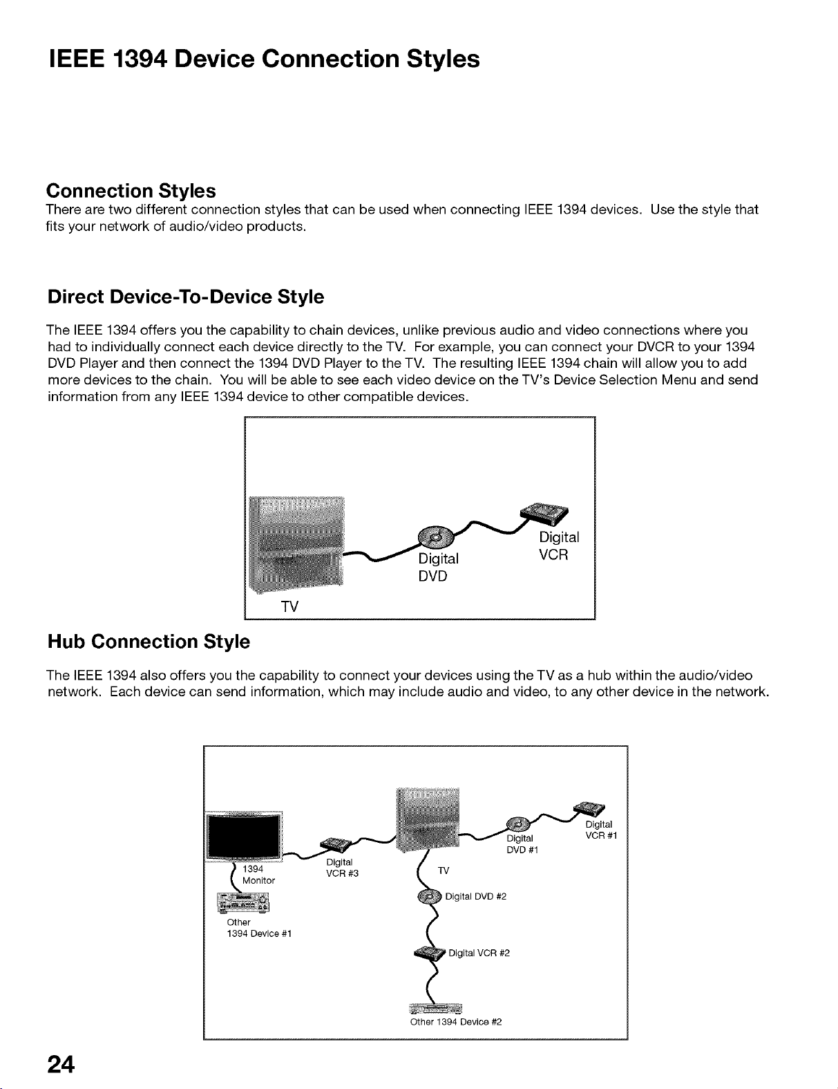
Direct Device-To-Device Style
The IEEE 1394 offers you the capability to chain devices, unlike previous audio and video connections where you
had to individually connect each device directly to the TV. For example, you can connect your DVCR to your 1394
DVD Player and then connect the 1394 DVD Player to the TV. The resulting IEEE 1394 chain will allow you to add
more devices to the chain. You will be able to see each video device on the TV's Device Selection Menu and send
information from any IEEE 1394 device to other compatible devices.
Digital
Digital
VCR
DVD
TV
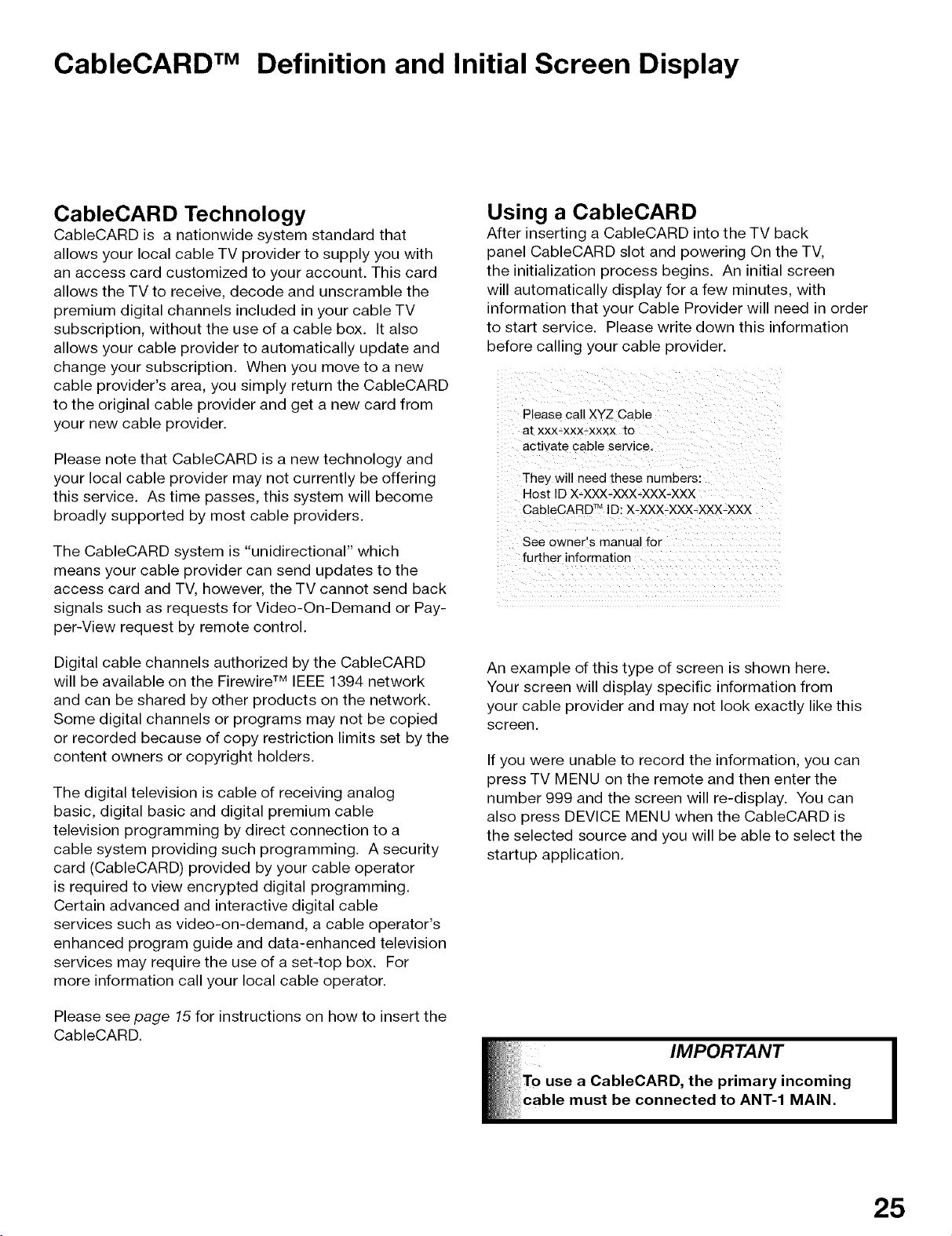
Hub Connection Style
The IEEE 1394 also offers you the capability to connect your devices using the TV as a hub within the audio/video
network. Each device can send information, which may include audio and video, to any other device in the network.
VCR #1
1394 VCR #3 TV
Monitor
Other
1394 Device #1
Digital
Digital
DVD #1
Digital DVD #2
Digital VCR #2
24
Other 1394 Device #2
CableCARD TM Definition and Initial Screen Display
CableCARD Technology
CableCARD is a nationwide system standard that
allows your local cable TV provider to supply you with
an access card customized to your account. This card
allows the TV to receive, decode and unscramble the
premium digital channels included in your cable TV
subscription, without the use of a cable box. It also
allows your cable provider to automatically update and
change your subscription. When you move to a new
cable provider's area, you simply return the CableCARD
to the original cable provider and get a new card from
your new cable provider.
Please note that CableCARD is a new technology and
your local cable provider may not currently be offering
this service. As time passes, this system will become
broadly supported by most cable providers.
The CableCARD system is "unidirectional" which
means your cable provider can send updates to the
access card and TV, however, the TV cannot send back
signals such as requests for Video-On-Demand or Pay-
per-View request by remote control.
Digital cable channels authorized by the CableCARD
will be available on the Firewire TM IEEE 1394 network
and can be shared by other products on the network.
Some digital channels or programs may not be copied
or recorded because of copy restriction limits set by the
content owners or copyright holders.
The digital television is cable of receiving analog
basic, digital basic and digital premium cable
television programming by direct connection to a
cable system providing such programming. A security
card (CableCARD) provided by your cable operator
is required to view encrypted digital programming.
Certain advanced and interactive digital cable
services such as video-on-demand, a cable operator's
enhanced program guide and data-enhanced television
services may require the use of a set-top box. For
more information call your local cable operator.
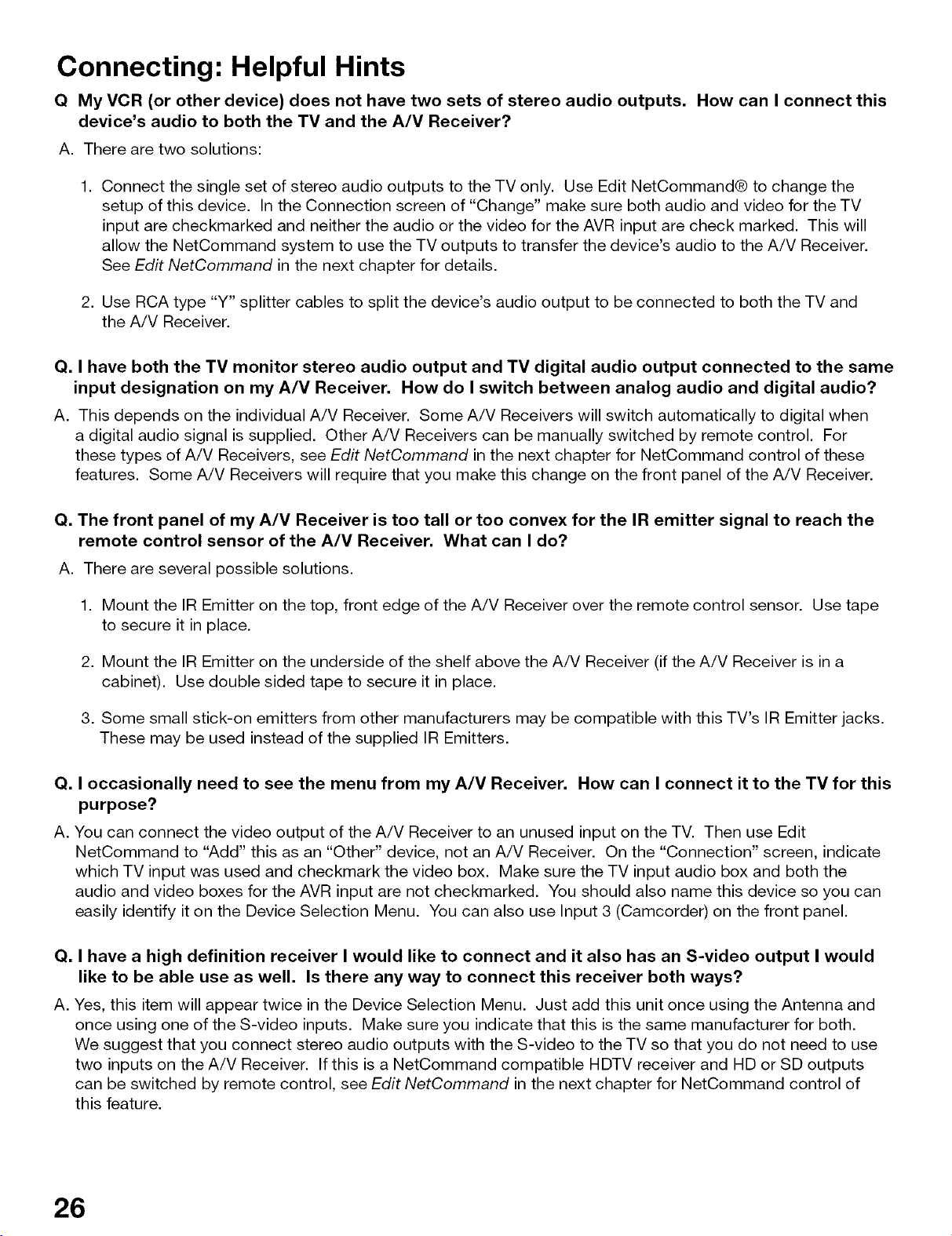
Using a CableCARD
After inserting a CableCARD into the TV back
panel CableCARD slot and powering On the TV,
the initialization process begins. An initial screen
will automatically display for a few minutes, with
information that your Cable Provider will need in order
to start service. Please write down this information
before calling your cable provider.
Please call XYZ Cable
at xxx-xxx-xxxx to
activate cable service.
They will need these numbers:
Host ID X-XXX-XXX-XXX-XXX
CableCARD TMID: X-XXX-XXX-)O(X-XXX
See owner s manual for
fu "ther information
An example of this type of screen is shown here.
Your screen will display specific information from
your cable provider and may not look exactly like this
screen.
If you were unable to record the information, you can
press TV MENU on the remote and then enter the
number 999 and the screen will re-display. You can
also press DEVICE MENU when the CableCARD is
the selected source and you will be able to select the
startup application.
Please see page 15 for instructions on how to insert the
CableCARD.
25
Connecting: Helpful Hints
Q My VCR (or other device) does not have two sets of stereo audio outputs. How can I connect this
device's audio to both the TV and the A/V Receiver?
A. There are two solutions:
1. Connect the single set of stereo audio outputs to the TV only. Use Edit NetCommand® to change the
setup of this device. In the Connection screen of "Change" make sure both audio and video for the TV
input are checkmarked and neither the audio or the video for the AVR input are check marked. This will
allow the NetCommand system to use the TV outputs to transfer the device's audio to the A/V Receiver.
See Edit NetCommand in the next chapter for details.
2. Use RCA type "Y" splitter cables to split the device's audio output to be connected to both the TV and
the A/V Receiver.
Q. I have both the TV monitor stereo audio output and TV digital audio output connected to the same
input designation on my A/V Receiver. How do I switch between analog audio and digital audio?
A. This depends on the individual A/V Receiver. Some A/V Receivers will switch automatically to digital when
a digital audio signal is supplied. Other A/V Receivers can be manually switched by remote control. For
these types of A/V Receivers, see Edit NetCommand in the next chapter for NetCommand control of these
features. Some A/V Receivers will require that you make this change on the front panel of the A/V Receiver.
Q. The front panel of my A/V Receiver is too tall or too convex for the IR emitter signal to reach the
remote control sensor of the A/V Receiver. What can I do?
A. There are several possible solutions.
1. Mount the IR Emitter on the top, front edge of the A/V Receiver over the remote control sensor. Use tape
to secure it in place.
2. Mount the IR Emitter on the underside of the shelf above the A/V Receiver (if the A/V Receiver is in a
cabinet). Use double sided tape to secure it in place.
3. Some small stick-on emitters from other manufacturers may be compatible with this TV's IR Emitter jacks.
These may be used instead of the supplied IR Emitters.
Q. I occasionally need to see the menu from my A/V Receiver. How can I connect it to the TV for this
purpose?
A. You can connect the video output of the A/V Receiver to an unused input on the TV. Then use Edit
NetCommand to "Add" this as an "Other" device, not an A/V Receiver. On the "Connection" screen, indicate
which TV input was used and checkmark the video box. Make sure the TV input audio box and both the
audio and video boxes for the AVR input are not checkmarked. You should also name this device so you can
easily identify it on the Device Selection Menu. You can also use Input 3 (Camcorder) on the front panel.
Q. I have a high definition receiver I would like to connect and it also has an S-video output I would
like to be able use as well. Is there any way to connect this receiver both ways?
A. Yes, this item will appear twice in the Device Selection Menu. Just add this unit once using the Antenna and
once using one of the S-video inputs. Make sure you indicate that this is the same manufacturer for both.
We suggest that you connect stereo audio outputs with the S-video to the TV so that you do not need to use
two inputs on the A/V Receiver. If this is a NetCommand compatible HDTV receiver and HD or SD outputs
can be switched by remote control, see Edit NetCommand in the next chapter for NetCommand control of
this feature.
26
NetCommand Setup and Ed,tmg
NetCommand® Pre-Memorized Devices ..................................................... 28
Remote Control Functions: Overview ........................................................... 29
Remote Control Functions: Operation, Care, Sleep Timer ......................... 30
NetCommand® OnScreen Buttons ............................................................... 31
3D Graphical kViSWP0Jl][Menu System ............................................................... 32
NetCommand® Initial Setup .......................................................................... 33
Edit NetCommand®
Adding an A/V Receiver ............................................................................ 35
Adding Devices .......................................................................................... 38
Changing, Deleting Devices, Finish Screen ........................................... 42
Device Selection Menu ................................................................................... 43
Using the Device Menu Button to Display Menus ....................................... 44
NetCommand® Pre-Memorized Devices
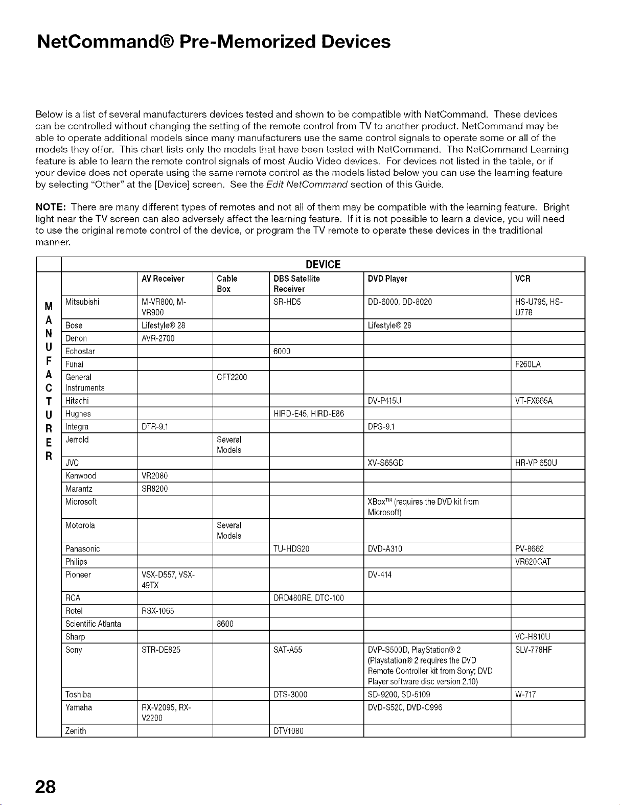
Below is a list of several manufacturers devices tested and shown to be compatible with NetCommand. These devices
can be controlled without changing the setting of the remote control from TV to another product. NetCommand may be
able to operate additional models since many manufacturers use the same control signals to operate some or all of the
models they offer. This chart lists only the models that have been tested with NetCommand. The NetCommand Learning
feature is able to learn the remote control signals of most Audio Video devices. For devices not listed in the table, or if
your device does not operate using the same remote control as the models listed below you can use the learning feature
by selecting "Other" at the [Device] screen. See the Edit NetCommand section of this Guide.
NOTE: There are many different types of remotes and not all of them may be compatible with the learning feature. Bright
light near the TV screen can also adversely affect the learning feature. If it is not possible to learn a device, you will need
to use the original remote control of the device, or program the TV remote to operate these devices in the traditional
manner.
DEVICE
AVReceiver Cable DBSSatellite DVDPlayer VCR
M Mitsubishi M-VR800,M- SR-HD5 DD-6000,DD-8020 HS-U795,HS-
A Bose Lifestyle@28 Lifestyle@28
N Denon AVR-2700
U Echostar 6000
F Funai F260LA
A General CFT2200
C Instruments
T Hitachi DV-P415U VT-FX665A
U Hughes HIRD-E45,HIRD-E86
R Integra DTR-9.1 DPS-9.1
E Jerrold Several
R Models
JVC XV-S65GD HR-VP650U
Kenwood VR2080
Marantz SR8200
Microsoft XBox (requirestheDVDkitfrom
Motorola Several
Panasonic TU-HDS20 DVD-A310 PV-8662
Philips VR620CAT
Pioneer VSX-D557,VSX- DV-414
RCA DRD480RE,DTC-IO0
Rotel RSX-1065
ScientificAtlanta 8600
Sharp VC-H810U
Sony STR-DE825 SAT-A55 DVP-S5OOD,PlayStation®2 SLV-778HF
Toshiba DTS-3000 SD-9200,SD-5109 W-717
Yamaha RX-V2095,RX- DVD-S520,DVD-C996
Zenith DTVl080
VR900 U778
49TX
V2200
Box Receiver
TM
Microsoft)
Models
(Playstation®2requirestheDVD
RemoteControllerkitfromSony;DVD
Playersoftwarediscversion2.10)
28
Remote Control Functions: Overview
Figure 1, following page
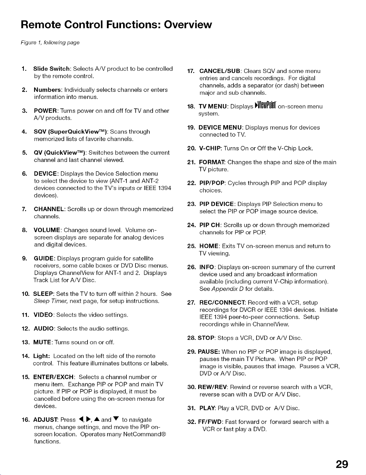
1. Slide Switch: Selects A/V product to be controlled
by the remote control.
2. Numbers: Individually selects channels or enters
information into menus.
3. POWER: Turns power on and off for TV and other
A/V products.
4. SQV (SuperQuickViewTM): Scans through
memorized lists of favorite channels.
5. QV (QuickViewTM): Switches between the current
channel and last channel viewed. 21.
.
DEVICE: Displays the Device Selection menu
to select the device to view (ANT-1 and ANT-2
devices connected to the TV's inputs or IEEE 1394
devices).
7. CHANNEL: Scrolls up or down through memorized
channels.
8. VOLUME: Changes sound level. Volume on-
screen displays are separate for analog devices
and digital devices.
g.
GUIDE: Displays program guide for satellite
receivers, some cable boxes or DVD Disc menus.
Displays ChannelView for ANT-1 and 2. Displays
Track List for A/V Disc.
10. SLEEP: Sets the TV to turn off within 2 hours. See
Sleep Timer, next page, for setup instructions.
11. VIDEO: Selects the video settings.
12. AUDIO: Selects the audio settings.
13. MUTE: Turns sound on or off.
14. Light: Located on the left side of the remote
control. This feature illuminates buttons or labels.
15. ENTER/EXCH: Selects a channel number or
menu item. Exchange PIP or POP and main TV
picture. If PIP or POP is displayed, it must be
cancelled before using the on-screen menus for
devices.
17. CANCEL/SUB: Clears SQV and some menu
entries and cancels recordings. For digital
channels, adds a separator (or dash) between
major and sub channels.
18. TV MENU: Displays dig llill[on-screen menu
system.
19.
DEVICE MENU: Displays menus for devices
connected to TV.
20.
V-CHIP: Turns On or Off the V-Chip Lock.
FORMAT: Changes the shape and size of the main
TV picture.
22.
PIP/POP: Cycles through PIP and POP display
choices.
23.
PIP DEVICE: Displays PIP Selection menu to
select the PIP or POP image source device.
24.
PIP OH: Scrolls up or down through memorized
channels for PIP or POE
25.
HOME: Exits TV on-screen menus and return to
TV viewing.
26.
INFO: Displays on-screen summary of the current
device used and any broadcast information
available (including current V-Chip information).
See Appendix D for details.
27.
REC/CONNECT: Record with a VCR, setup
recordings for DVCR or IEEE 1394 devices. Initiate
IEEE 1394 peer-to-peer connections. Setup
recordings while in ChannelView.
28.
STOP: Stops a VCR, DVD or A/V Disc.
29.
PAUSE: When no PIP or POP image is displayed,
pauses the main TV Picture. When PIP or POP
image is visible, pauses that image. Pauses a VCR,
DVD or A/V Disc.
30.
REW/REV: Rewind or reverse search with a VCR,
reverse scan with a DVD or A/V Disc.
31.
PLAY: Play a VCR, DVD or A/V Disc.
16. ADJUST: Press 4, _', • and • to navigate
menus, change settings, and move the PIP on-
screen location. Operates many NetCommand®
functions.
32.
FF/FWD: Fast forward or forward search with a
VCR or fast play a DVD.
29
Remote Control Functions:Operation, Care, Sleep Timer
CABLE/DBS/DTV DVD
VCR
_lllr_UO,O
0
4QQ Q oU,OE
DEVICE CHANNEL VOLUME
MITSUBISHI
Care
For Best Results from the Remote Control:
• Be within 20 feet of the equipment.
• Do not press two or more buttons at the same
time unless instructed to do so.
• Do not allow unit to get wet or become heated.
• Avoid dropping on hard surfaces.
• Do not use harsh chemicals to clean. Use only
a soft, lightly moistened cloth.
• Do not mix new and old batteries.
• Do not heat, take apart or throw batteries into
fire.
• Use only AAA alkaline batteries.
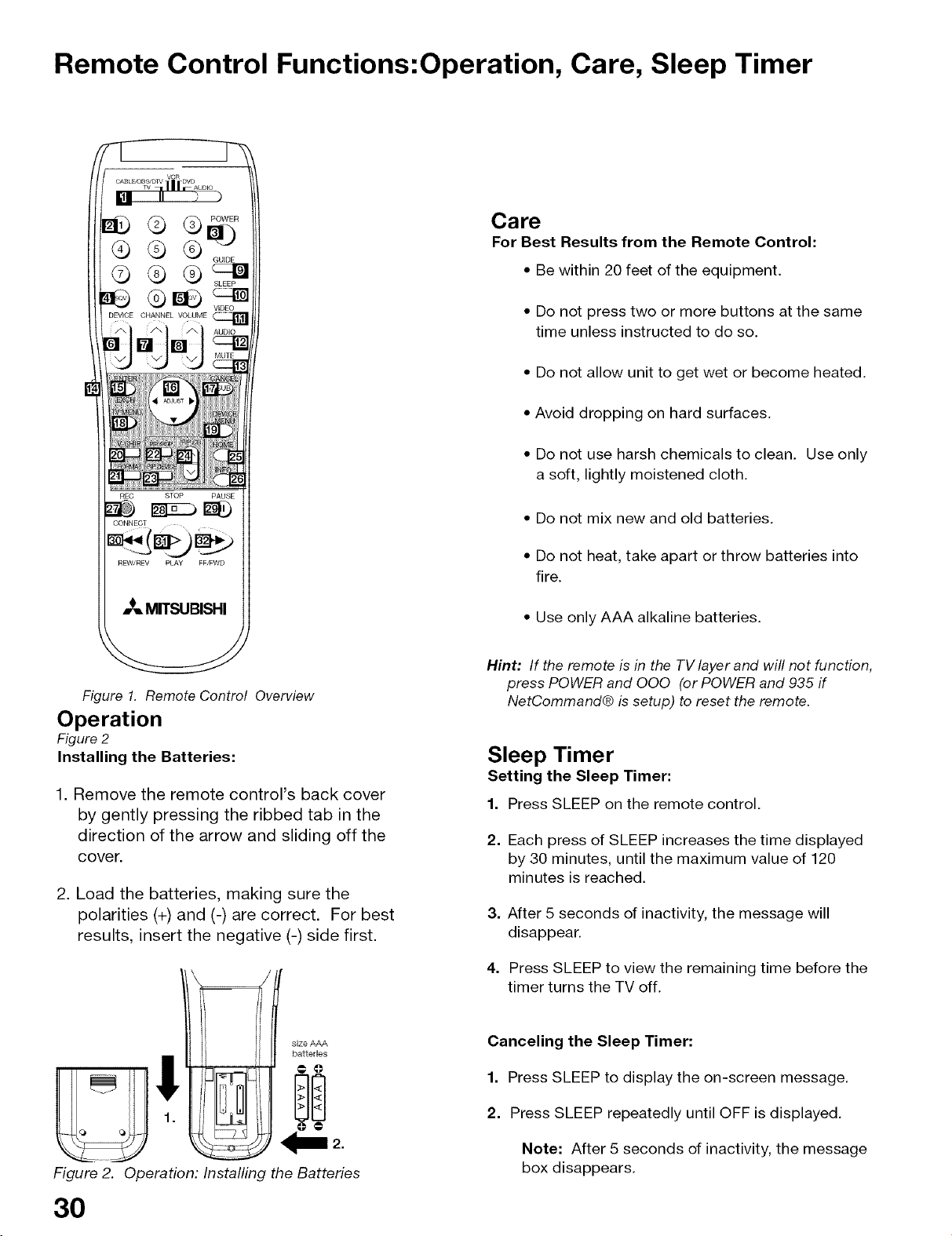
Figure 1. Remote Control Overview
Operation
Figure 2
Installing the Batteries:
1. Remove the remote control's back cover
by gently pressing the ribbed tab in the
direction of the arrow and sliding off the
cover.
2. Load the batteries, making sure the
polarities (+) and (-) are correct. For best
results, insert the negative (-) side first.
size AAA
batteries
!
Hint: If the remote is in the TV layer and will not function,
press POWER and 000 (or POWER and 935 if
NetCommand@ is setup) to reset the remote.
Sleep Timer
Setting the Sleep Timer:
1. Press SLEEP on the remote control.
2. Each press of SLEEP increases the time displayed
by 30 minutes, until the maximum value of 120
minutes is reached.
3. After 5 seconds of inactivity, the message will
disappear.
4. Press SLEEP to view the remaining time before the
timer turns the TV off.
Canceling the Sleep Timer:
1. Press SLEEP to display the on-screen message.
2. Press SLEEP repeatedly until OFF is displayed.
Fi rure 2. C
30
oeration: Installing the Batteries
Note: After 5 seconds of inactivity, the message
box disappears.
 Loading...