

Page 1
General ........................
00
WORKSHOP MANUAL
SUPPLEMENT
FOREWORD
This manual outlines changes in servicing
procedures related to the chassis including vehicle
inspections, adjustments, and improvements in the
newly equipped models. Use the following manuals
in combination with this manual required.
TECHNICAL INFORMATION MANUAL
PYDE9802
WORKSHOP MANUAL
CHASSIS GROUP PWDE9803
ENGINE GROUP PWEEjjjj
(Looseleaf edition)
ELECTRICAL WIRING PHDE9802
PHDE9802-A
BODY REPAIR MANUAL PBDE9802
PARTS CATALOGUE
SPACE RUNNER B608V500Aj
SPACE WAGON B608W500Aj
Engine .........................
Fuel ...........................
Engine Cooling .................
Intake and Exhaust ............
Engine Electrical ...............
Engine and Emission Control ....
Clutch .........................
Automatic Transmission ........
Front Axle ......................
Wheel and Tyre .................
Front Suspension ...............
Service Brakes .................
Steering ........................
11
13
14
15
16
17
21
23
26
31
33
35
37
All information, illustrations and product
descriptions contained in this manual are current
as at the time of publication. We, however, reserve
the right to make changes at any time without prior
notice or obligation.
“GDI” is th e trade mark which Mitsubishi Motors
Corporation holds.
E
Mitsubishi Motors Corporation May 1999
Page 2

GENERAL
CONTENTS
00-1
HOW TO USE THIS MANUAL 2..............
Model Indications 2............................
VEHICLE IDENTIFICATION 3.................
Models 3......................................
Model Code 3.................................
Chassis Number 4.............................
Engine Model Number 5........................
New Vehicles 5................................
MAJOR SPECIFICATIONS 6..................
Page 3

00-2
GENERAL -
How to Use This Manual
HOW TO USE THIS MANUAL
MODEL INDICATIONS
The following abbreviations are used in this manual for classification of model types.
2000: Indicates models equipped with the 2,000 mL <4G63> petrol engine.
2400: Indicates models equipped with the 2,400 mL <4G64> petrol engine.
MPI: Indicates the multipoint injection, or engine equipped with the multipoint injection.
GDI: Indicates the gasoline direct injection, or engine equipped with the gasoline direct injection.
SOHC: Indicates an engine with the single overhead camshaft, or models equipped with such an
engine.
DOHC: Indicates an engine with the double overhead camshaft, or models equipped with such an
engine.
M/T: Indicates the manual transmission, or models equipped with the manual transmission.
A/T: Indicates the automatic transmission, or models equipped with the automatic transmission.
A/C: Indicates the air conditioner.
Page 4
GENERAL -
Vehicle Identification
00-3
VEHICLE IDENTIFICATION
MODELS
Model code Engine model Transmission model Fuel supply system
N63W SNUEL6/R6 4G63-SOHC (1,997 mL) F5M42 (2WD-5M/T) MPI
SNFEL6
SNUJL6
SRUEL6/R6 F4A42 (2WD-4A/T)
SRFEL6
SRUJL6
N64W SNHCL6 4G64-DOHC-GDI F5M42 (2WD-5M/T) GDI
(2,351 mL)
SNGCL6
SNHGL6
SRHCL6 F4A42 (2WD-4A/T)
123456
SRGCL6
SRHGL6
7
89
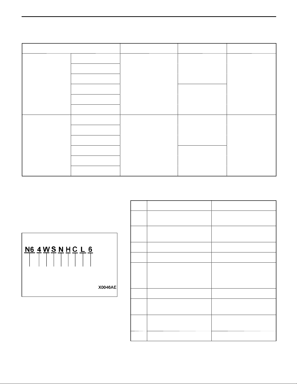
MODEL CODE
No. Items Contents
1 Development N6: SPACE RUNNER
(2WD)
2 Engine type 3: 2,000 mL petrol engine
4: 2,400 mL petrol engine
3 Body type W: Wagon
4 Body style S: 3-door station wagon
5 Transmission type N: 5-speed manual
transmission
R: 4-speed automatic
transmission
6 Trim level U,F,H,G: GLX
7 Specification engine
feature
8 Steering wheel location L: Left hand
9 Destination 6: For Europe
E,J: MPI-SOHC
C,G: GDI-DOHC
R: Right hand
Page 5
00-4
GENERAL -
CHASSIS NUMBER
Vehicle Identification
23 4
1
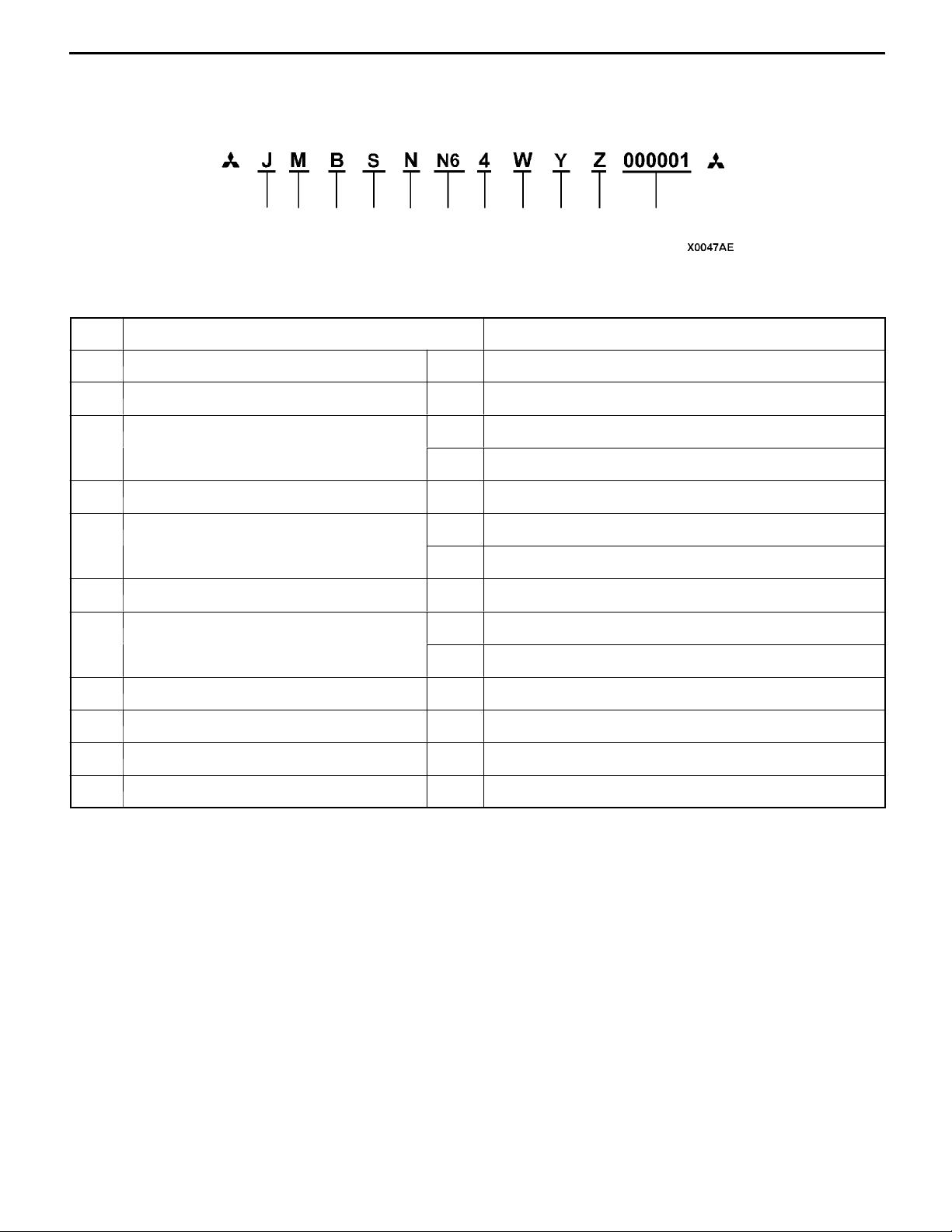
No. Items Contents
1 Fixed figure J Asia
2 Distribution channel M Japan channel
3 Destination A For Europe, right hand drive
4 Body style S 3-door station wagon
5 Transmission type N 5-speed manual transmission
6 Development order N6 SP ACE RUNNER (2WD)
7 Engine 3 4G63: 1,997 mL petrol engine
67891110
5
B For Europe, left hand drive
R 4-speed automatic transmission
4 4G64: 2,351 mL petrol engine
8 Sort W Station wagon
9 Model year Y 2000
10 Plant Z Okazaki Motor Vehicle Works
11 Serial number - -
Page 6
GENERAL -
Vehicle Identification
00-5
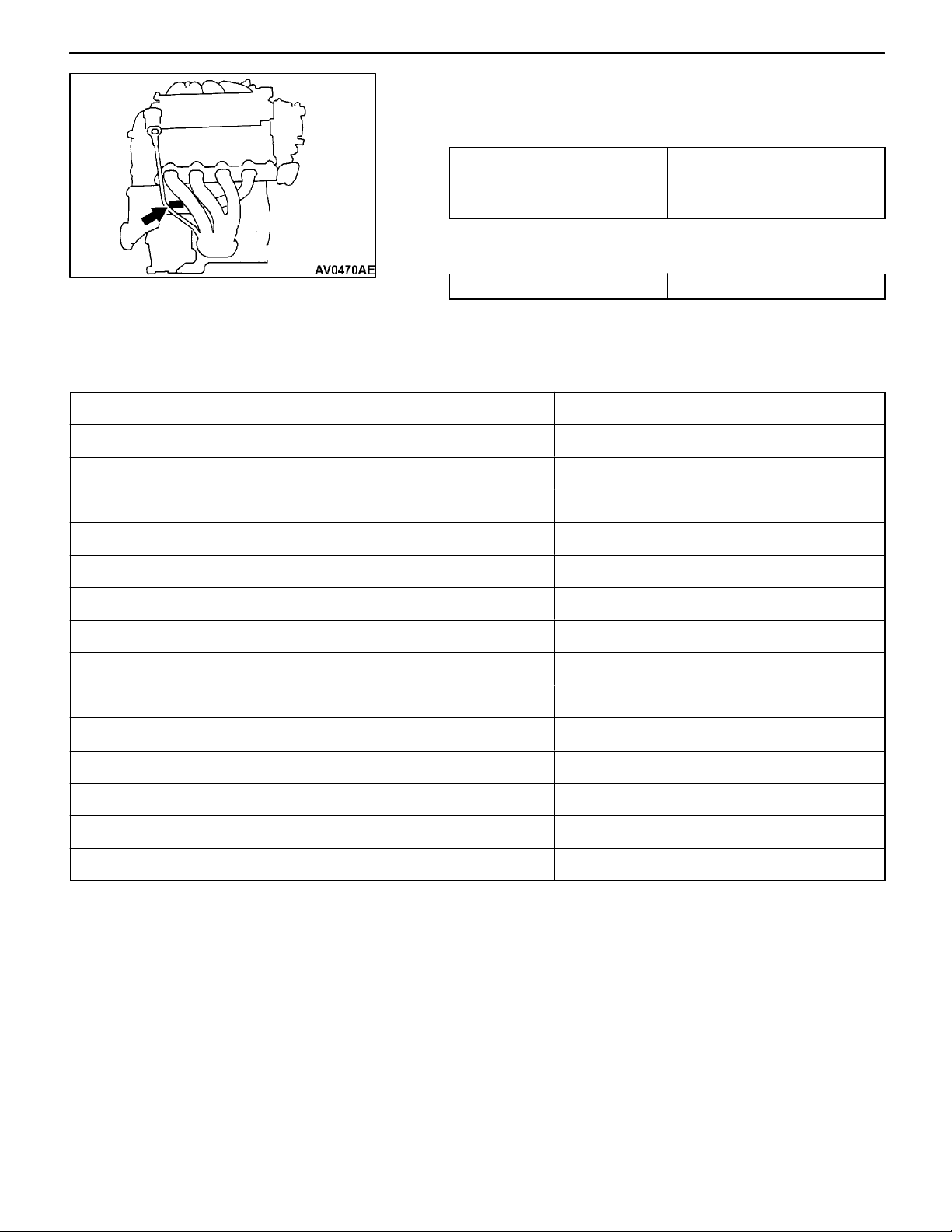
ENGINE MODEL NUMBER
1. The engine model number is stamped at the cylinder
block as shown in the following.
Engine model Engine displacement mL
4G63
4G64
1,997
2,351
2. The engine serial number is stamped near the engine
model number.
Engine serial number AA0201 to YY9999
NEW VEHICLES
New vehicles has been added as shown below.
New vehicle has been developed from the respective basic vehicle. Specification show only a particular
part of the new vehicle. For the remaining par, refer to specifications for basic vehicle.
New vehicle Basic vehicle
N63W SNUEL6 N61W SNUCL6
N63W SNUER6 N61W SNUCR6
N63W SNFEL6 N61W SNFCL6
N63W SNUJL6 N61W SNUGL6
N63W SRUEL6 N61W SRUCL6
N63W SRUER6 N61W SRUCR6
N63W SRFEL6 N61W SRFCL6
N63W SRUJL6 N61W SRUGL6
N64W SNHCL6 N61W SNUCL6
N64W SNGCL6 N61W SNFCL6
N64W SNHGL6 N61W SNUGL6
N64W SRHCL6 N61W SRUCL6
N64W SRGCL6 N61W SRFCL6
N64W SRHGL6 N61W SRUGL6
Page 7
00-6
GENERAL -
MAJOR SPECIFICATIONS
Major Specifications
3
3*
Items
5
2
9
7
N63W
SNUEL6,
SNUER6,
SNFEL6,
SNUJL6
4
1
N63W
SRUEL6,
SRUER6,
SRFEL6,
SRUJL6
8
N64W
SNHCL6,
SNGCL6,
SNHGL6
6
N64W
SRHCL6,
SRGCL6,
SRHGL6
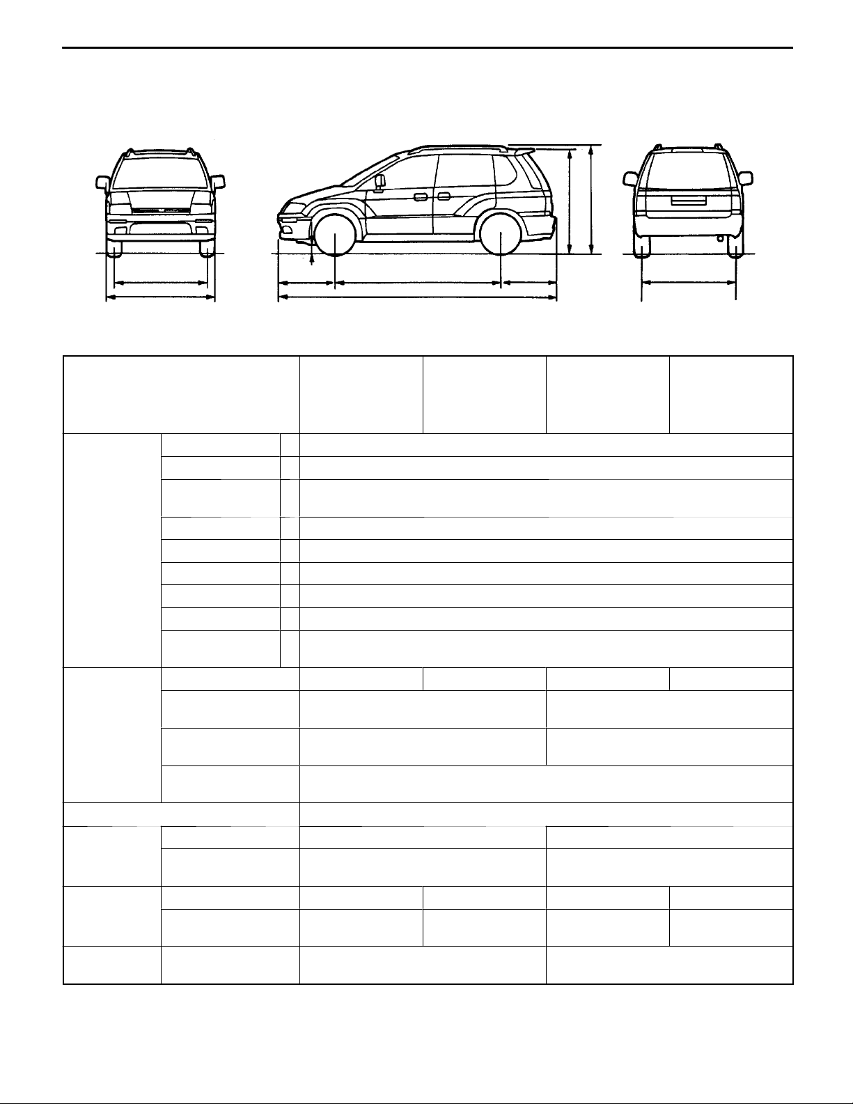
Vehicle Overall length 1 4,290
dimensions
mm
Overall width 2 1,695
Overall height
(unladen)
3 1,650
1,680*
Wheelbase 4 2,550
Track-front 5 1,460
Track-rear 6 1,465
Overhang-front 7 890
Overhang-rear 8 850
Ground clear-
9 155
ance (unladen)
Vehicle Kerb weight 1,360 1,380 1,400 1,420
weight kg
Max. gross vehicle
1,880 1,920
weight
Max. axle weight
1,000 1,050
rating-front
Max. axle weight
900
rating-rear
Seating capacity 5
Engine Model No. 4G63 4G64
Total displacementmL1,997 2,351
Transmis- Model No. F5M42 F4A42 F5M42 F4A42
sion
Fuel system Fuel supply system Electronically controlled multipoint
Type 5-speed manual 4-speed
automatic
5-speed manual 4-speed
automatic
Gasoline Direct Injection
injection
*: Vehicles with roof rails
Page 8

ENGINE
<4G6-MPI>
CONTENTS
11C-1
GENERAL 3.................................
Outline of Changes 3..........................
GENERAL INFORMATION 3..................
SERVICE SPECIFICATIONS 3.................
SEALANTS 4................................
SPECIAL TOOLS 5..........................
ON-VEHICLE SERVICE 6.....................
Drive Belt Tension Check and Adjustment 6......
Ignition Timing Check 9........................
Idle Speed Check 10...........................
Idle Mixture Check 10..........................
Compression Pressure Check 11................
Manifold Vacuum Check 12.....................
Lash Adjuster Check 12........................
CRANKSHAFT PULLEY 15..................
CAMSHAFT AND CAMSHAFT OIL SEAL 16..
OIL PAN 19.................................
CRANKSHAFT OIL SEAL 21.................
CYLINDER HEAD GASKET 24...............
TIMING BELT 27............................
TIMING BELT B 31..........................
ENGINE ASSEMBLY 34.....................
Page 9

11C-2
NOTES
Page 10

ENGINE <4G6-MPI> -
General/General Information/
Service Specifications
11C-3
GENERAL
OUTLINE OF CHANGES
The following service procedures have been established in line with the addition of vehicles with 4G63-MPI
engine.
GENERAL INFORMATION
Items 4G63
Total displacement mL 1,997
Bore´Stroke mm 85.0´88.0
Compression ratio 10.0
Combustion chamber Pentroof type
Camshaft arrangement SOHC
Number of valve Intake 8
Exhaust 8
V alve timing Intake Opening BTDC 11
Closing ABDC 53
Exhaust Opening BBDC 63
Closing ATDC 21
Fuel system Electronically controlled multipoint fuel injection
Rocker arm Roller type
Auto-lash adjuster Equipped
_
_
_
_
SERVICE SPECIFICATIONS
Items Standard value Limit
Alternator drive belt checked
When adjusting the alternator
drive belt
Vibration frequency Hz 177 - 232 -
Tension N 343 - 588 -
Deflection (Reference value) mm 6.7 - 9.8 -
Vibration frequency Hz 201 - 222 -
Tension N 441 - 539 -
When replacing the alternator
drive belt
Power steering oil pump and A/C
compressor drive belt tension
(When checked)
Deflection (Reference value) mm 7.2 - 8.4 -
Vibration frequency Hz 241 - 276 -
Tension N 637 - 833 -
Deflection (Reference value) mm 5.0 - 6.4 -
Vibration frequency Hz 108 - 132 -
Tension N 392 - 588 -
Deflection (Reference value) mm 11.7 - 15.3 -
Page 11

11C-4
Items LimitStandard value
ENGINE <4G6-MPI> -
Service Specifications/Sealants
Power steering oil pump and A/C
compressor drive belt tension
(When adjusted)
Power steering oil pump and A/C
compressor drive belt tension
(When replaced)
Basic ignition timing 5_ BTDC ± 3_ -
Ignition timing Approx.10_ BTDC -
Idle speed r/min 750 ± 100 -
CO contents % 0.5 or less -
HC contents ppm 100 or less -
Compression pressure kPa-r/min 1,400 Min. 1,060
Compression pressure difference of all cylinder kPa - Max. 100
Intake manifold vacuum kPa - Min. 69
Cylinder head bolt shank length mm - 99.4
Vibration frequency Hz 1 14 - 126 -
Tension N 441 - 539 -
Deflection (Reference value) mm 12.5 - 14.3 -
Vibration frequency Hz 137 - 157 -
Tension N 637 - 834 -
Deflection (Reference value) mm 8.8 - 11.0 -
Auto-tensioner push rod movement mm Within 1 -
Timing belt tension torque Nm (Reference value) 3.5 -
Auto-tensioner rod protrusion amount mm 3.8 - 4.5 -
Timing belt B tension mm 5-7 -
SEALANTS
Items Specified sealants Remarks
Rocker cover and cylinder head
Semi-circular packing
Oil pan
Thermostat case
Flywheel or drive plate bolt 3M Stud Locking 4170 or equivalent -
3M ATD Part No.8660 or equivalent -
MITSUBISHI GENUINE PART
MD970389 or equivalent
Semi-drying sealant
Page 12
ENGINE <4G6-MPI> -
Special Tools
SPECIAL TOOLS
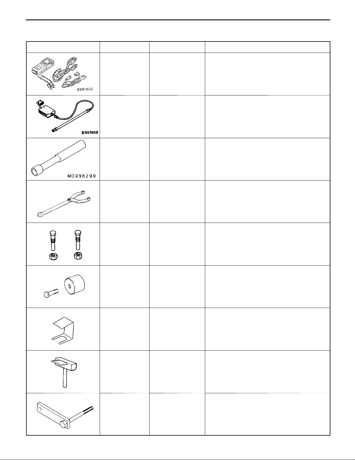
Tool Number Name Use
11C-5
MB991502 MUT-II sub assem-
bly
MB991668 Belt tension meter
set
MD998299 MAS screwdriver Adjustment of the mixture adjusting screw
MB990767 End yoke holder D Holding the camshaft sprocket
D Checking the ignition timing
D Checking the idle speed
D Erasing diagnosis code
D Measuring the drive belt tension
Measuring the drive belt tension
(used together with the MUT-II)
<Vehicles without catalytic converter>
D Holding the crankshaft sprocket
MD998719 or
MD998754
MD998713 Camshaft oil seal
MD998443 Auto-lash adjuster
MD998727 Oil pan remover Removal of oil pan
Crankshaft pulley
holder pin
installer
holder
D Holding the camshaft sprocket
D Holding the crankshaft sprocket
Press-in of the camshaft oil seal
Supporting of auto-lash adjuster
MD998781 Flywheel stopper Securing the flywheel or drive plate
Page 13
11C-6
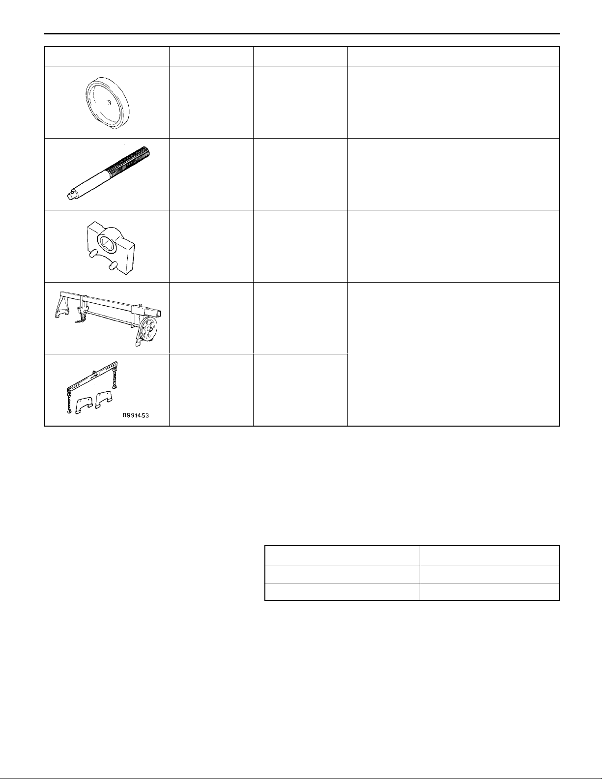
Tool UseNameNumber
ENGINE <4G6-MPI> -
Special Tools/On-vehicle Service
MD998776 Crankshaft rear oil
seal installer
MB990938 Handle Press-in of the crankshaft rear oil seal
MD998767 Tension pulley
socket wrench
GENERAL
SERVICE
TOOL
MZ203827
Engine lifter Supporting the engine assembly during
Press-in of the crankshaft rear oil seal
Timing belt tension adjustment
removal and installation of the transmission
MB991453 Engine hanger
assembly
ON-VEHICLE SERVICE
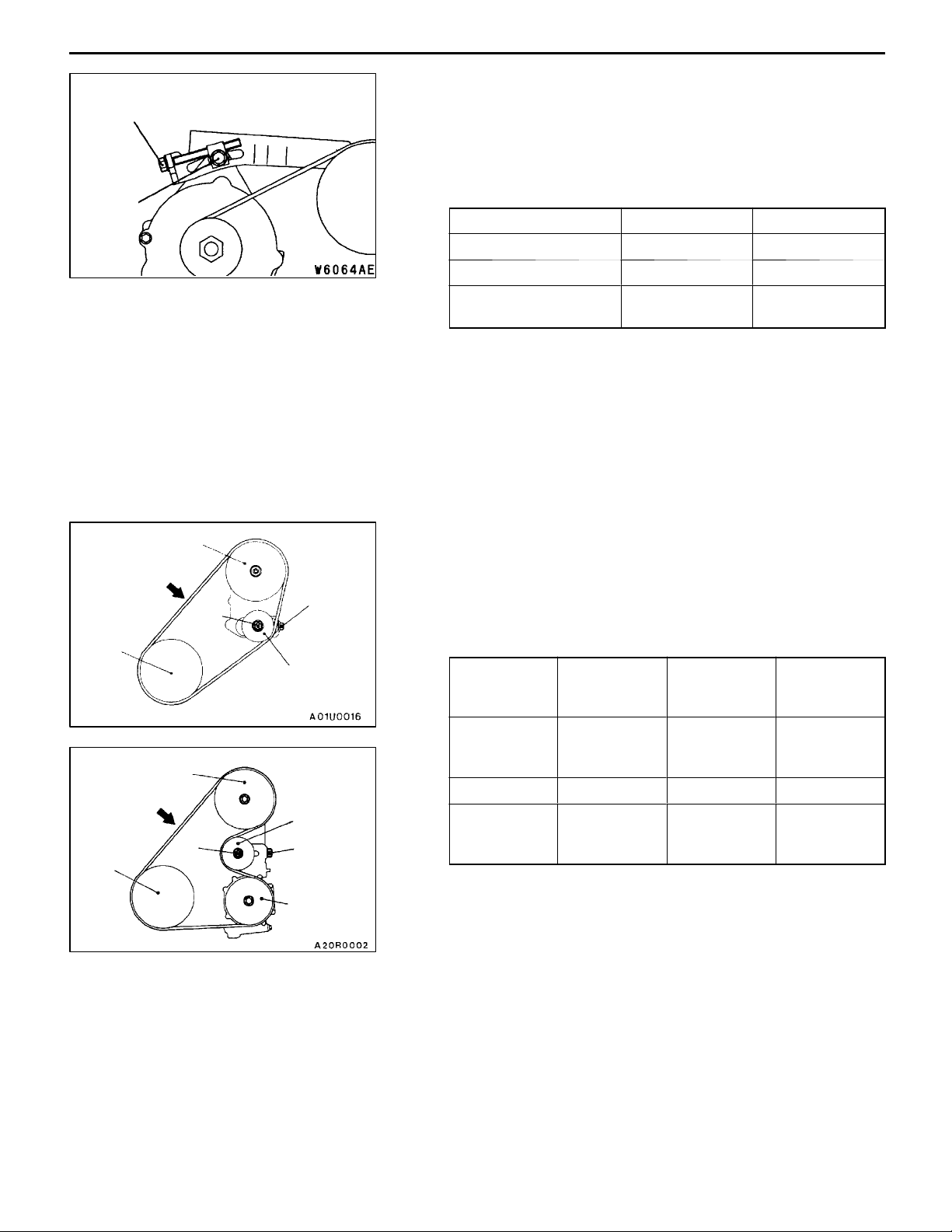
DRIVE BELT TENSION CHECK AND
ADJUSTMENT
ALTERNATOR DRIVE BELT TENSION CHECK
Check the drive belt tension in the following procedure.
Standard value:
Vibration frequency Hz 177 - 232
Tension N 343 - 588
Deflection (Reference value) mm 6.7 - 9.8
Page 14
ENGINE <4G6-MPI> -
On-vehicle Service
11C-7
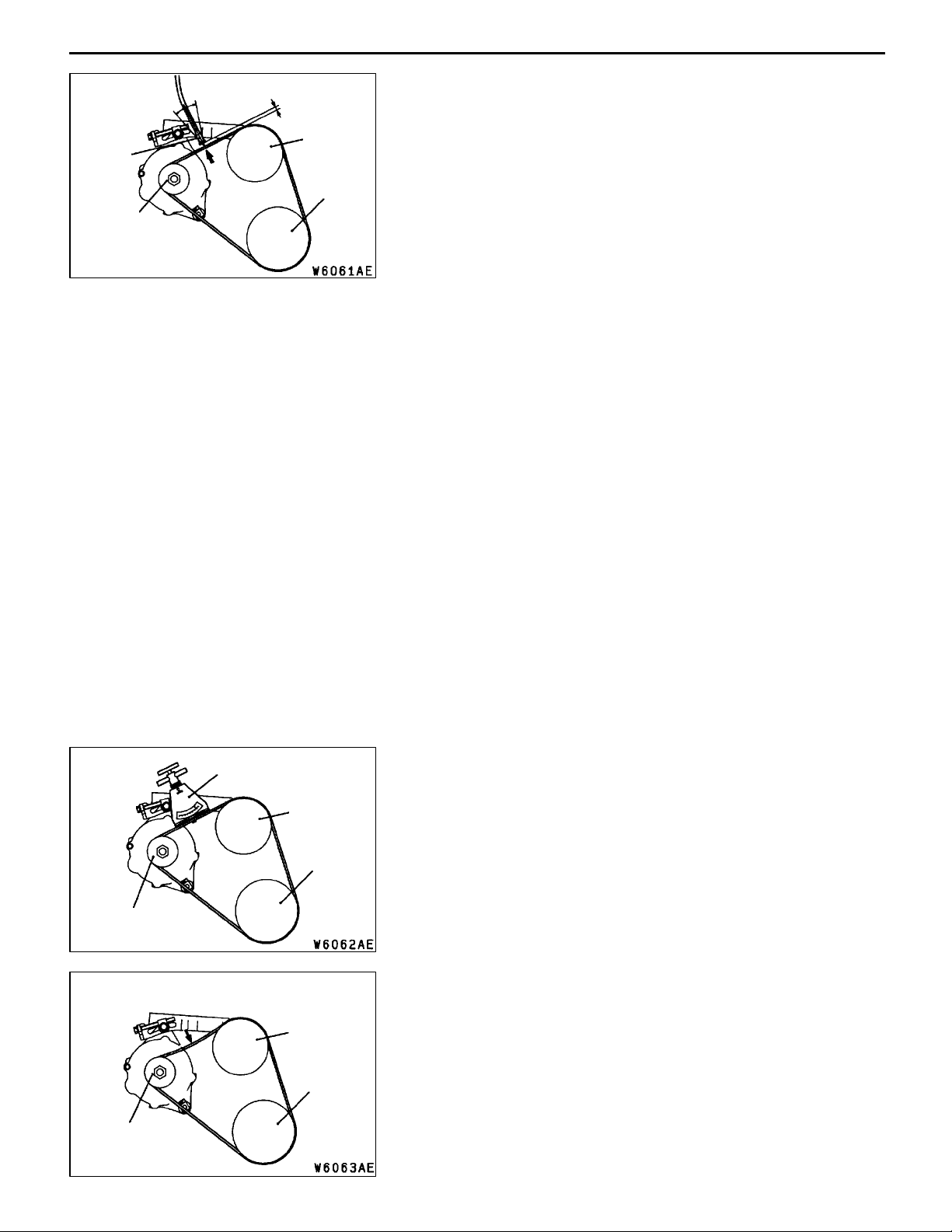
MB991668
(Microphone)
Alternator
pulley
15
15
_
_
10 - 20 mm
Water pump
pulley
Crankshaft
pulley
1. Connect the special tool (belt tension meter set) to the
MUT-II.
2. Connect the MUT-II to the diagnosis connector.
3. Turn the ignition switch to ON a n d select “Belt Tension
Measurement” from th e menu screen.
4. Hold the microphone to the middle of the drive belt
between the pulleys (at the place indicated by the arrow),
about 10 - 20 mm away from the rear surface of the
belt and so that it is perpendicular to the belt (within
an angle of ± 15_).
5. Gently tap the middle of the belt between the pulleys
(the place indicated by the arrow) with your finger as
shown in the illustration, and check that the vibration
frequency of the belt is within the standard value.
Caution
(1) The temperature of the surface of the belt should
be as close as possible to normal temperature.
(2) Do not let any contaminants such as water or
oil get onto the microphone.
(3) If strong gusts of wind blow against the
microphone or if there are any loud sources of
noise nearby, the values measured by the
microphone may not correspond to actual values.
(4) If the microphone is touching the belt while the
measurement is being made, the values measured
by the microphone may not correspond to actual
values.
(5) Do not take the measurement while the vehicle’s
engine is running.
<When using the MUT-II>
Alternator
pulley
Alternator
pulley
Belt tension gauge
98 N
Water pump
pulley
Crankshaft
pulley
Water pump
pulley
Crankshaft
pulley
<When using a tension gauge>
Use a belt tension gauge to check that the belt tension is
within the standard value.
<Belt deflection check>
Apply 98 N of force to the middle of the drive belt between
the pulleys (at the place indicated by the arrow) and check
that the amount of deflection is within the standard value.
Page 15
11C-8
Adjusting bolt
Lock bolt
ENGINE <4G6-MPI> -
ALTERNATOR DRIVE BELT TENSION ADJUSTMENT
1. Loosen the nut of the alternator pivot bolt.
2. Loosen the lock bolt.
3. Use the adjusting bolt to adjust the belt tension and belt
deflection to the standard values.
Standard value:
Items When adjusting When replacing
Vibration frequency Hz 201 - 222 241 - 276
Tension N 441 - 539 637 - 833
Deflection
(Reference value) mm
4. Tighten the nut of the alternator pivot bolt.
Tightening torque: 49 Nm
5. Tighten the lock bolt.
Tightening torque: 22 Nm
6. Tighten the adjusting bolt.
Tightening torque: 5 Nm
On-vehicle Service
7.2 - 8.4 5.0 - 6.4
<Vehicles without A/C>
Oil pump pulley
98 N
Crankshaft
pulley
<Vehicles with A/C>
Oil pump pulley
98 N
Crankshaft
pulley
A
POWER STEERING OIL PUMP AND AIR CONDITIONER
COMPRESSOR DRIVE BELT TENSION CHECK AND
ADJUSTMENT
A
B
1. Check if the belt tension is within the standard value
using one of the methods below.
Standard value:
Tensioner pulley
Tensioner
pulley
B
A/C
compressor
pulley
Items When
checked
Vibration
frequency
Hz
Tension N 392 - 588 441 - 539 637 - 834
Deflection
(Reference
value) mm
108 - 132 114 - 126 137 - 157
11.7 - 15.3 12.5 - 14.3 8.8 - 11.0
When a
used belt is
installed
When a new
belt is
installed
<When measuring the vibration frequency>
With your finger tip lightly tap the centre of the belt between
the pulleys in the location shown by the arrow in t he
illustration and then measure the belt vibration frequency.
NOTE
Refer to P.11C-7 for information regarding the vibration
frequency measurement method using MUT-II.
<When measuring the tension>
Use a belt tension gauge to measure the belt tension.
Page 16

ENGINE <4G6-MPI> -
<When measuring the deflection>
Apply 98 N of pressure against the location between
the pulleys shown by the arrow in the illustration and
then measure the deflection.
2. If the tension or deflection is outside the standard value,
adjust by the following procedure.
(1) Loosen tensioner pulley fixing nut A.
(2) Adjust the amount of belt deflection using adjusting
(3) Tighten fixing nut A.
(4) Check the belt deflection amount and tension, and
On-vehicle Service
bolt B.
Tightening torque: 25 Nm
readjust if necessary.
Caution
Check after turning the crankshaft once or more
clockwise (right turn).
11C-9
IGNITION TIMING CHECK
1. Before inspection, set the vehicle to the pre-inspection
condition.
2. Connect the MUT-II to the diagnosis connector.
3. Set up a timing light.
4. Start the engine and run at idle.
5. Check that engine idle speed is within the standard value.
Standard value: 750±100 r/min
6. Select No.17 of the MUT-II Actuator test.
7. Check that basic ignition timing is within the standard
value.
Standard value: 5_BTDC±3
8. If the basic ignition timing is outside the standard value,
inspect th e MPI system while referring to GROUP 13A
- Troubleshooting.
9. Press the MUT-II clear key (Select a forced driving cancel
mode) to release the Actuator test.
Caution
If the test is not cancelled, a forced driving will
continue for 27 minutes. Driving under this condition
may damage the engine.
10. Check that ignition timing is at the standard value.
_
Standard value: approx. 10_BTDC
NOTE
1. Ignition timing is variable within about ± 7_, even
under normal operating.
2. And it is automatically further advanced by about
5_ from standard value at higher altitudes.
Page 17

11C-10
ENGINE <4G6-MPI> -
IDLE SPEED CHECK
1. Before inspection, set the vehicle to the pre-inspection
condition.
2. Turn the ignition switch to “LOCK” (OFF) position and
connect the MUT-II to the diagnosis connector.
3. Check the basic ignition timing.
Standard value: 5_BTDC±3
4. Run the engine at idle for 2 minutes.
5. Check the idle speed. Select item No. 22 and take a
reading of the idle speed.
Standard value: 750±100 r/min
NOTE
The idle speed is controlled automatically by the idle speed
control (ISC) system.
6. If the idle speed is outside the standard value, inspect
the MPI components by referring to GROUP 13A Troubleshooting.
On-vehicle Service
_
IDLE MIXTURE CHECK
1. Before inspection, set the vehicle to the pre-inspection
condition.
2. Turn the ignition switch to “LOCK” (OFF) position and
connect the MUT-II to the diagnosis connector.
3. Check that the basic ignition timing is within the standard
value.
Standard value: 5_BTDC±3
4. Run the engine at 2,500 r/min for 2 minutes.
5. Set the CO, HC tester.
6. Check the CO contents and the HC contents at idle.
Standard value
CO contents: 0.5% or less
HC contents: 100 ppm or less
7. If there is a deviation from the standard value, check
the following items:
D Diagnosis output
D Closed-loop control (When the closed-loop control
is normal, the output signal of the oxygen sensor
changes between 0 - 400 mV and 600 - 1,000 mV
at idle.)
D Fuel pressure
D Injector
D Ignition coil, spark plug cable, spark plug
D Leak in the EGR system and in the EGR valve
D Evaporative emission control system
D Compression pressure
_
Page 18
ENGINE <4G6-MPI> -
NOTE
Replace the three way catalyst when the CO and HC
contents are not within the standard value, even though
the result of the inspection is normal on all items.
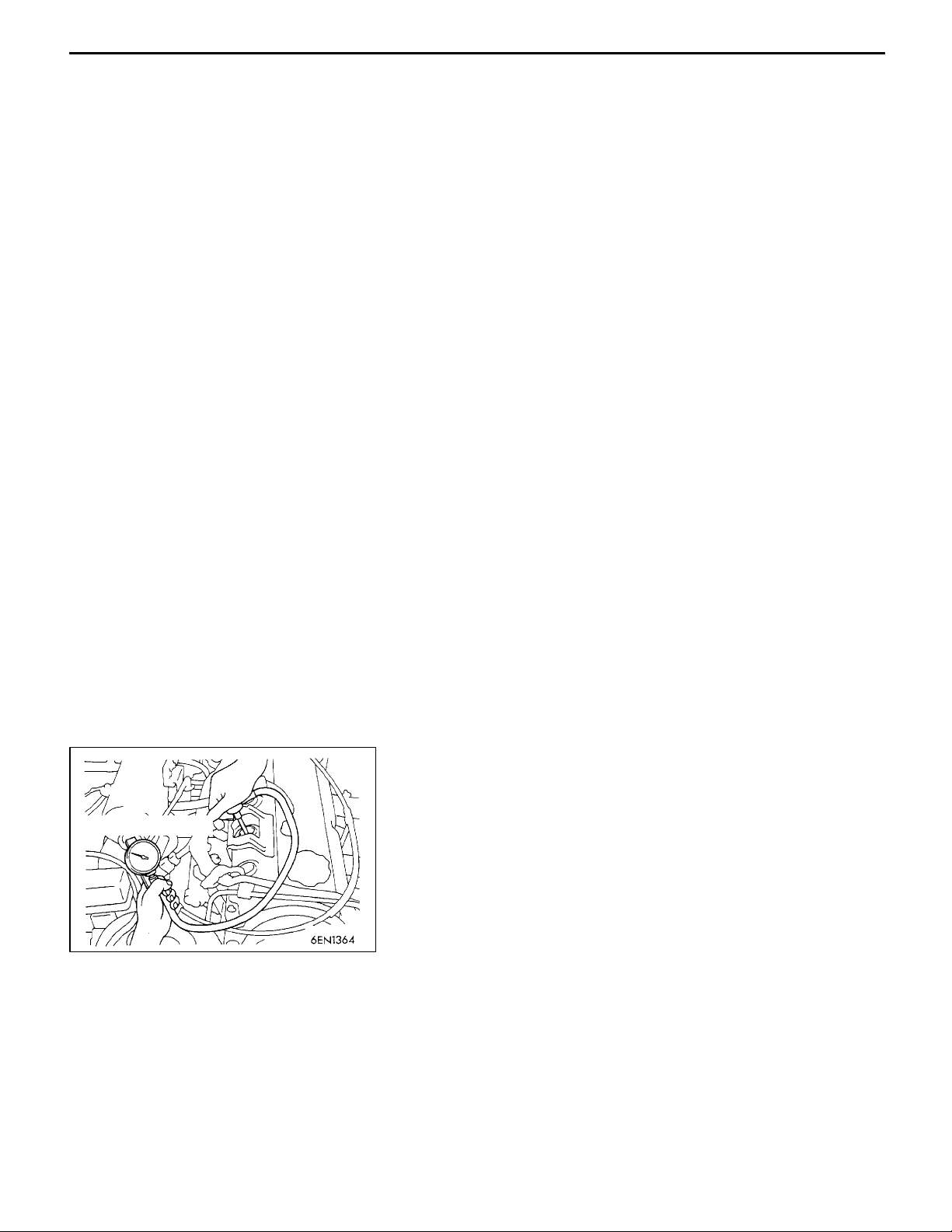
COMPRESSION PRESSURE CHECK
1. Before inspection, check that the engine oil, starter and
battery are normal. In addition, set the vehicle to the
pre-inspection condition.
2. Disconnect the spark plug cables.
3. Remove all of the spark plugs.
4. Disconnect the crank angle sensor connector.
NOTE
Doing this will prevent the engine-ECU <M/T> or
engine-A/T-ECU <A/T> from carrying out ignition and fuel
injection.
5. Cover the spark plug hole with a shop towel etc., and
after the engine has been cranked, check that no foreign
material is adhering to the shop towel.
On-vehicle Service
11C-11
Compression gauge
Caution
1. Keep away from the spark plug hole when
cranking.
2. If compression is measured with water, oil, fuel,
etc., that has come from cracks inside the cylinder,
these materials will become heated and will gush
out from the spark plug hole, which is dangerous.
6. Set compression gauge to one of the spark plug holes.
7. Crank the engine with the throttle valve fully open and
measure the compression pressure.
Standard value (at engine speed of 250 - 400 r/min):
1,400 kPa
Limit (at engine speed of 250- 400 r/min):
Min. 1,060 kPa
8. Measure the compression pressure for all the cylinders,
and check that the pressure differences of the cylinders
are below the limit.
Limit: Max. 100 kPa
9. If there is a cylinder with compression or a compression
difference that is outside th e limit, pour a small amount
of engine oil through the spark plug hole, and repeat
the operations in steps 7 and 8.
(1) If the compression increases after oil is added, the
cause of the malfunction is a worn or damaged piston
ring and/or cylinder inner surface.
Page 19
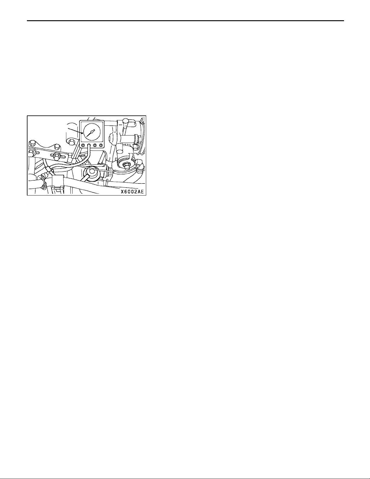
11C-12
Vacuum gauge
ENGINE <4G6-MPI> -
(2) If the compression does not rise after oil is added,
10. Connect the crank angle sensor connector.
11. Install the spark plugs and spark plug cables.
12. Use the MUT-II to erase the diagnosis codes.
NOTE
This will erase the diagnosis code resulting from the crank
angle sensor connector being disconnected.
MANIFOLD VACUUM CHECK
1. Before inspection, set the vehicle to the pre-inspection
condition.
2. Attach a three-way union to the vacuum hose between
the fuel pressure regulator and the air intake plenum,
and connect a vacuum gauge.
3. Start the engine and check that idle speed is within
standard value. Then read off the vacuum gauge.
Limit: Min. 69 kPa
On-vehicle Service
the cause is a burnt or defective valve seat, or pressure
is leaking from the gasket.
LASH ADJUSTER CHECK
If an abnormal noise (knocking) that seems to be coming
from the lash adjuster is heard after starting the engine and
does not stop, carry out the following check.
NOTE
(1) The abnormal noise which is caused by a problem
with the lash adjusters is generated after the engine
is started, and will vary according to the engine speed.
However, this noise is not related to the actual engine
load.
Because of this, if the noise does not occur
immediately after the engine is started, if it does not
change in accordance with the engine speed, or if
it changes in accordance with the engine load, the
source of the noise is not the lash adjusters.
(2) If there is a problem with the lash adjusters, the noise
will almost never disappear, even if the engine has
been run at idle to let it warm up.
The only case where the noise might disappear is
if the oil in the engine has not been looked after
properly and oil sludge has caused the lash adjusters
to stick.
1. Start the engine.
2. Check that the noise occurs immediately after the engine
is started, and that the noise changes in accordance
with changes in the engine speed.
If the noise does not occur immediately after the engine
is started, or if it does not change in accordance with
the engine speed, the problem is not being caused by
the lash adjusters, so check for some other cause of
the problem. Moreover, if the noise does not change in
accordance with the engine speed, the cause of the
problem is probably not with the engine. (In these cases,
the lash adjusters are normal.)
Page 20
ENGINE <4G6-MPI> -
3. While the engine is idling, check that the noise level does
not change when the engine load is varied (for example,
by shifting from N ® D).
If the noise level changes, the cause of the noise is
probably parts striking because of worn crankshaft
bearings or connecting rod bearings. (In such cases, the
lash adjusters are normal.)
4. After the engine has warmed up, run it at idle and check
if any noise can be heard.
If the noise has become smaller or disappeared, oil sludge
could make the lash adjusters stick. Clean the lash
adjusters. (Refer to the Engine Workshop Manual.) If not
improved, go to step 5.
5. Bleed air from the lash adjusters.
6. If the noise has not disappeared even after the air
bleeding, clean the lash adjusters. (Refer to the Engine
Workshop Manual.)
<LASH ADJUSTER AIR BLEEDING>
NOTE
(1) If the vehicle is parked on a slope for a long period
(2) After parking the vehicle for long periods, the oil drains
(3) If either of the above situations occur, the abnormal
On-vehicle Service
of time, the amount of oil inside the lash adjuster
will decrease, and air may get into the high pressure
chamber when starting the engine.
out of the oil passage, an d it takes time for the oil
to be supplied to the lash adjuster, so air can get
into the high pressure chamber.
noise can be eliminated by bleeding the air from inside
the lash adjusters.
11C-13
Good
1. Check the engine oil and replenish or replace the oil
if necessary.
NOTE
(1) If there is a only small amount of oil, air will be drawn
in through the oil screen and will get into the oil
passage.
(2) If the amount of oil is greater than normal, then the
oil will being mixed by the crankshaft and a large
amount of air may get mixed into the oil.
(3) If the oil is degenerated, air and oil will not separate
easily in oil, and the amount of air mixed into the
oil will increase.
Page 21
11C-14
ENGINE <4G6-MPI> -
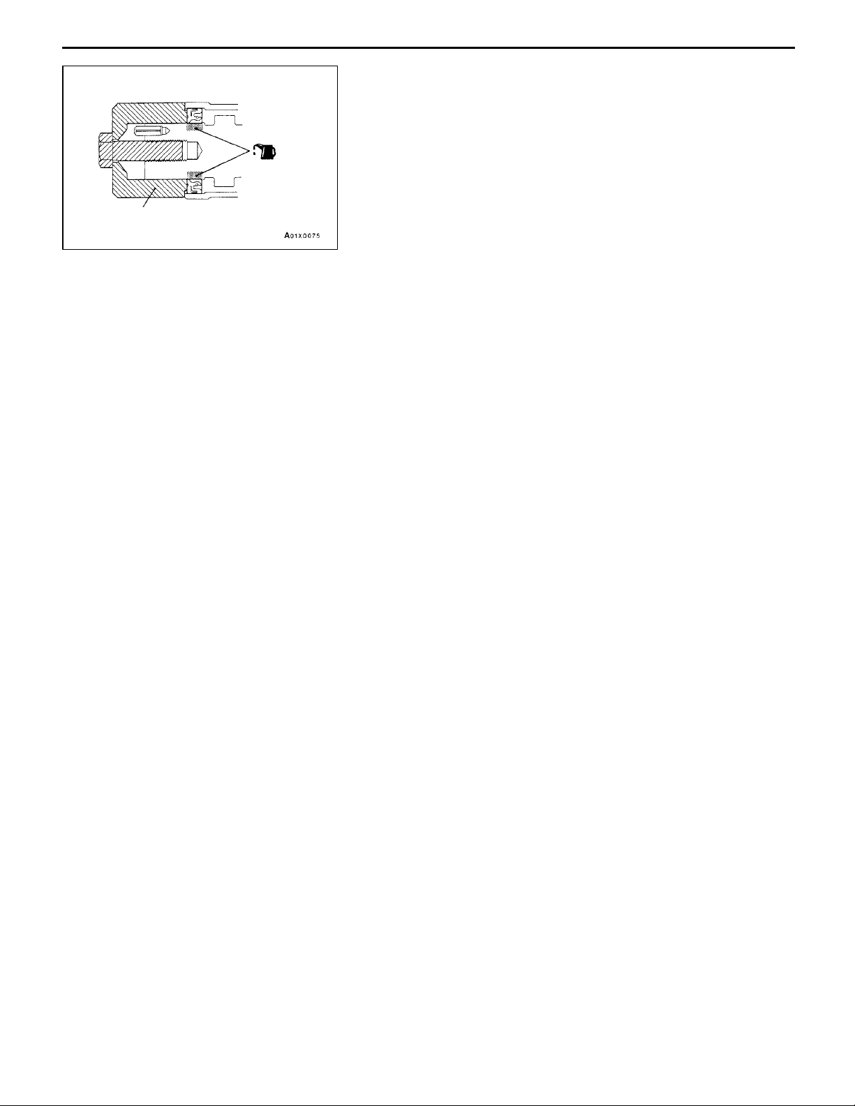
(4) If the air which has been mixed in with the oil due
Highpressure
chamber
On-vehicle Service
to any of the above reasons gets into the high pressure
chamber of the lash adjuster, the air inside the high
pressure chamber will be compressed when the valve
is open and the lash adjuster will over-compress,
resulting in abnormal noise when the valve closes.
This is the same effect as if the valve clearance is
adjusted to be too large by mistake. If the air inside
the lash adjusters is then released, the operation
of the lash adjusters will return to normal.
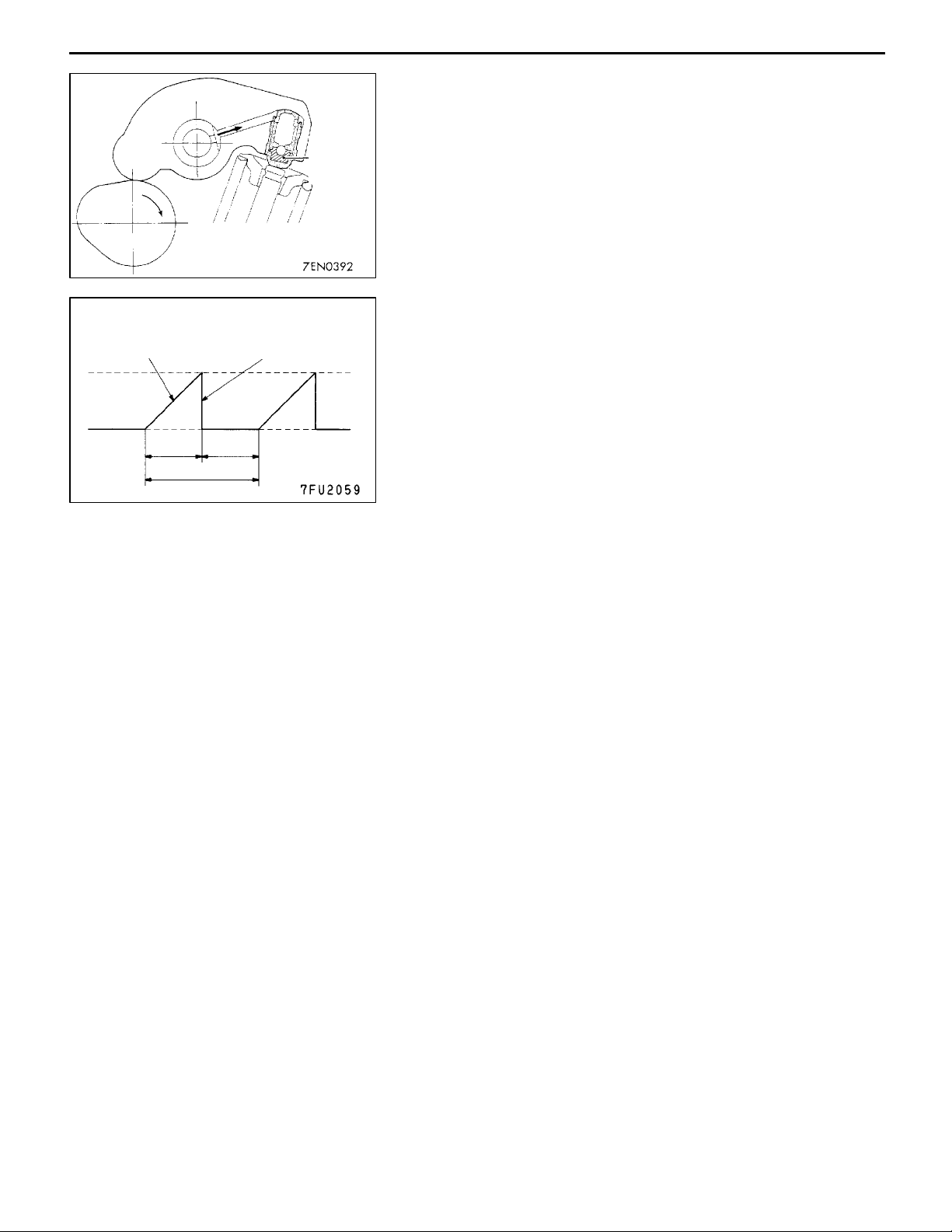
Drive pattern for air bleeding
Gradually open the
throttle valve.
Approx.
3,000 r/min
Idle speed
15
seconds
Once
Close the throttle
valve.
15
seconds
2. Run the engine at idle for 1 - 3 minutes to let it warm
up.
3. With no load on the engine, repeat the drive pattern shown
in the illustration at left and check if the abnormal noise
disappears. (The noise should normally disappear after
10 - 30 repetitions, but if there is no change in the noise
level after 30 repetitions or more, the problem is probably
not due to air inside the lash adjusters.)
4. After the noise has disappeared, repeat the drive pattern
shown in the illustration at left a further 5 times.
5. Run the engine at idle for 1 - 3 minutes and check that
the noise has disappeared.
Page 22
ENGINE <4G6-MPI> -
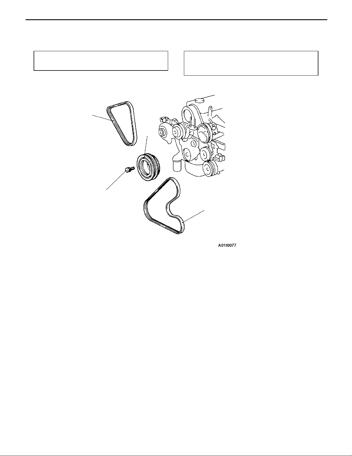
CRANKSHAFT PULLEY
REMOVAL AND INSTALLATION
Crankshaft Pulley
11C-15
Pre-removal Operation
D Under Cover Removal
2
Post-installation Operation
D Drive Belt Tension Adjustment (Refer to P.11C-6.)
D Under Cover Installation
3
25 Nm
1
Removal steps
1. Drive belt (Power steering and
A/C)
2. Drive belt (Alternator)
3. Crankshaft pulley
Page 23
11C-16
ENGINE <4G6-MPI> -
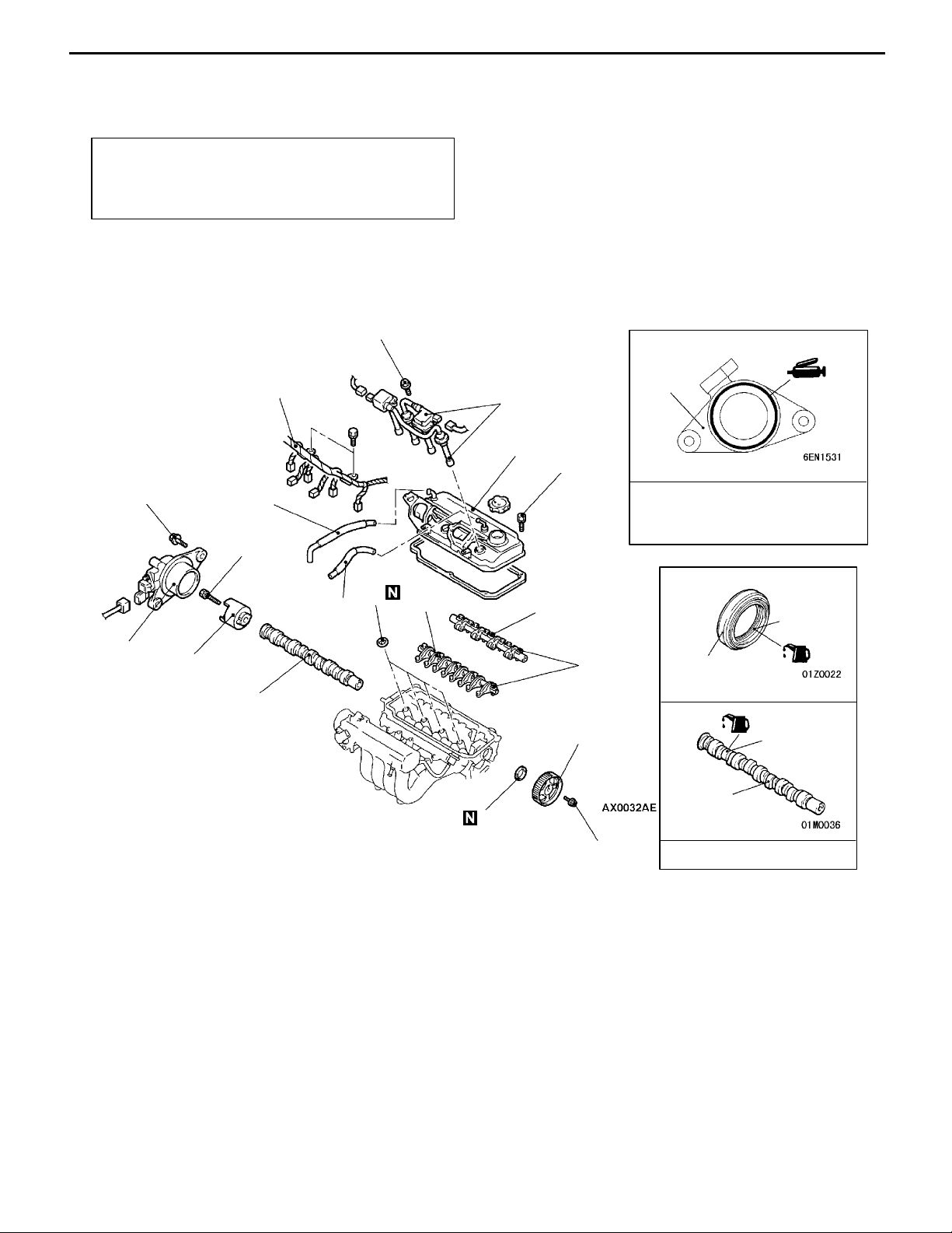
Camshaft and Camshaft Oil Seal
CAMSHAFT AND CAMSHAFT OIL SEAL
REMOVAL AND INSTALLATION
Pre-removal and Post-installation Operation
D Air Cleaner Removal and Installation
D Timing Belt Removal and Installation (Refer to
P.11C-27.)
10 Nm
(f 3 ± 1 mm)
14 Nm
6
1
2
6
5
3.4 Nm
4
22 Nm
10
3
7
12
11
28 - 34 Nm
Sealant:
MITSUBISHI GENUINE PART
MD970389 or equivalent
Lip section
9
13
8
Cam section
and journal
section
13
9
AA""CA
Removal steps
1. Control harness connection
2. Spark plug cable and ignition coil
3. PCV hose connection
4. Breather hose
5. Rocker cover
6. Camshaft position sensor support
7. Camshaft position sensing cylinder
8. Camshaft sprocket
"BA
AB""AA
AB""AA
88 Nm
9. Camshaft oil seal
10. Spark plug guide oil seal
11. Rocker arm and shaft assembly
12. Rocker arm and shaft assembly
13. Camshaft
Engine oil
(intake side)
(exhaust side)
Page 24
MB990767
ENGINE <4G6-MPI> -
MD998719 or
MD998754
Camshaft and Camshaft Oil Seal
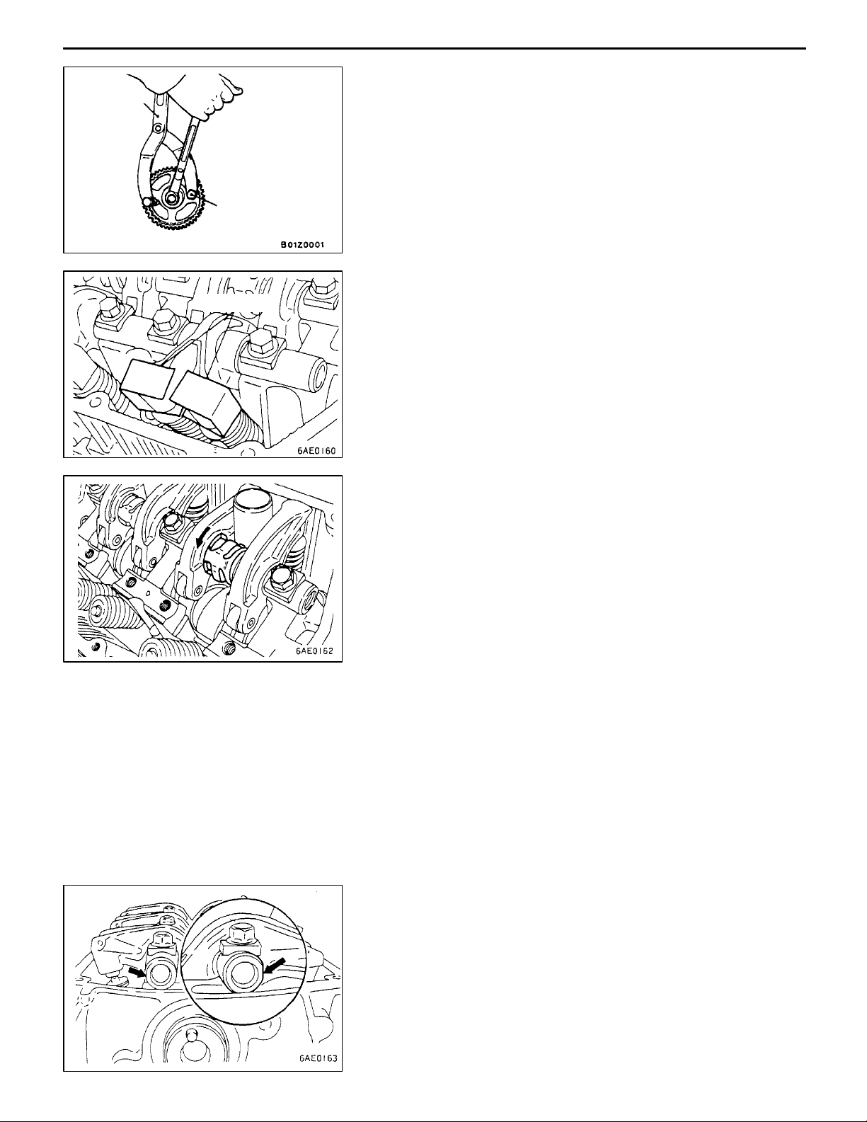
REMOVAL SERVICE POINTS
AA"
CAMSHAFT SPROCKET REMOVAL
11C-17
MD998443
AB"
Before removing the rocker arm an d shaft assembly, install
the special tools as shown in the illustration so that the lash
adjusters will not fall out.
ROCKER ARM AND SHAFT ASSEMBLY
REMOVAL
INSTALLATION SERVICE POINTS
"AA
1. Temporarily tighten the rocker shaft with the bolt so that
2. Fit the rocker shaft spring from the above and position
3. Remove the special tool for fixing the lash adjuster.
ROCKER ARM AND SHAFT ASSEMBLY
INSTALLATION
all rocker arms on the inlet valve side do not push the
valves.
it so that it is right angles to the plug guide.
NOTE
Install the rocker shaft spring before installing the rocker
arm and rocker arm shaft on the exhaust side.
4. Confirm that the rocker shaft notch is in the direction
shown in the diagram.
Page 25
11C-18
ENGINE <4G6-MPI> -
Camshaft and Camshaft Oil Seal
MD998713
"BA
1. Apply engine oil to the camshaft oil seal lip.
2. Use the special tool to press-fit the camshaft oil seal.
"CA
Use the special tool to stop the camshaft sprocket from turning
in the same way as was done during removal, and then tighten
the bolts to the specified torque.
CAMSHAFT OIL SEAL INSTALLATION
CAMSHAFT SPROCKET INSTALLATION
Page 26
ENGINE <4G6-MPI> -
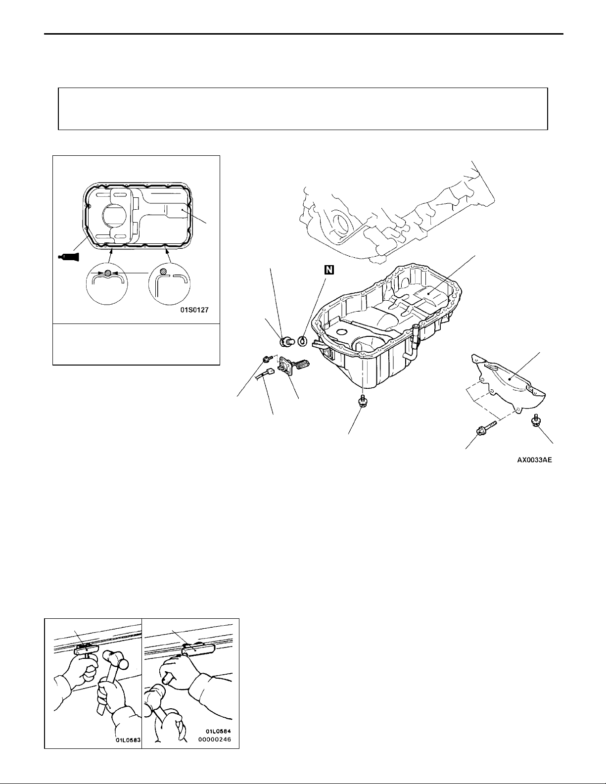
OIL PAN
REMOVAL AND INSTALLATION
Pre-removal and Post-installation Operation
D Under Cover Removal and Installation
D Engine Oil Draining and Supplying
5
Oil Pan
D Oil Level Gauge Removal and Installation
D Front Exhaust Pipe Removal and Installation
11C-19
f 4 ± 1mm
Groove
Sealant:
MITSUBISHI GENUINE PART
MD970389 or equivalent
Removal steps
"AA
1. Drain plug
2. Drain plug gasket
3. Harness connector
Bolt
hole
9Nm
39 Nm
1
3
6
2
AA"
9Nm
44 Nm
4. Bell housing cover
5. Oil pan
6. Oil level sensor
5
4
9Nm
MD998727
MD998727
REMOVAL SERVICE POINT
AA"
After removing the oil pa n mounting bolts, remove the oil
pan with the special tool and a brass bar.
Caution
Perform this slowly to avoid deformation of the oil pan
flange.
OIL PAN REMOVAL
Page 27

11C-20
Drain plug
gasket
ENGINE <4G6-MPI> -
INSTALLATION SERVICE POINT
"AA
Oil pan side
Install the drain plug gasket in the direction so that it faces
as shown in the illustration.
Oil Pan
DRAIN PLUG GASKET INSTALLATION
Page 28
ENGINE <4G6-MPI> -
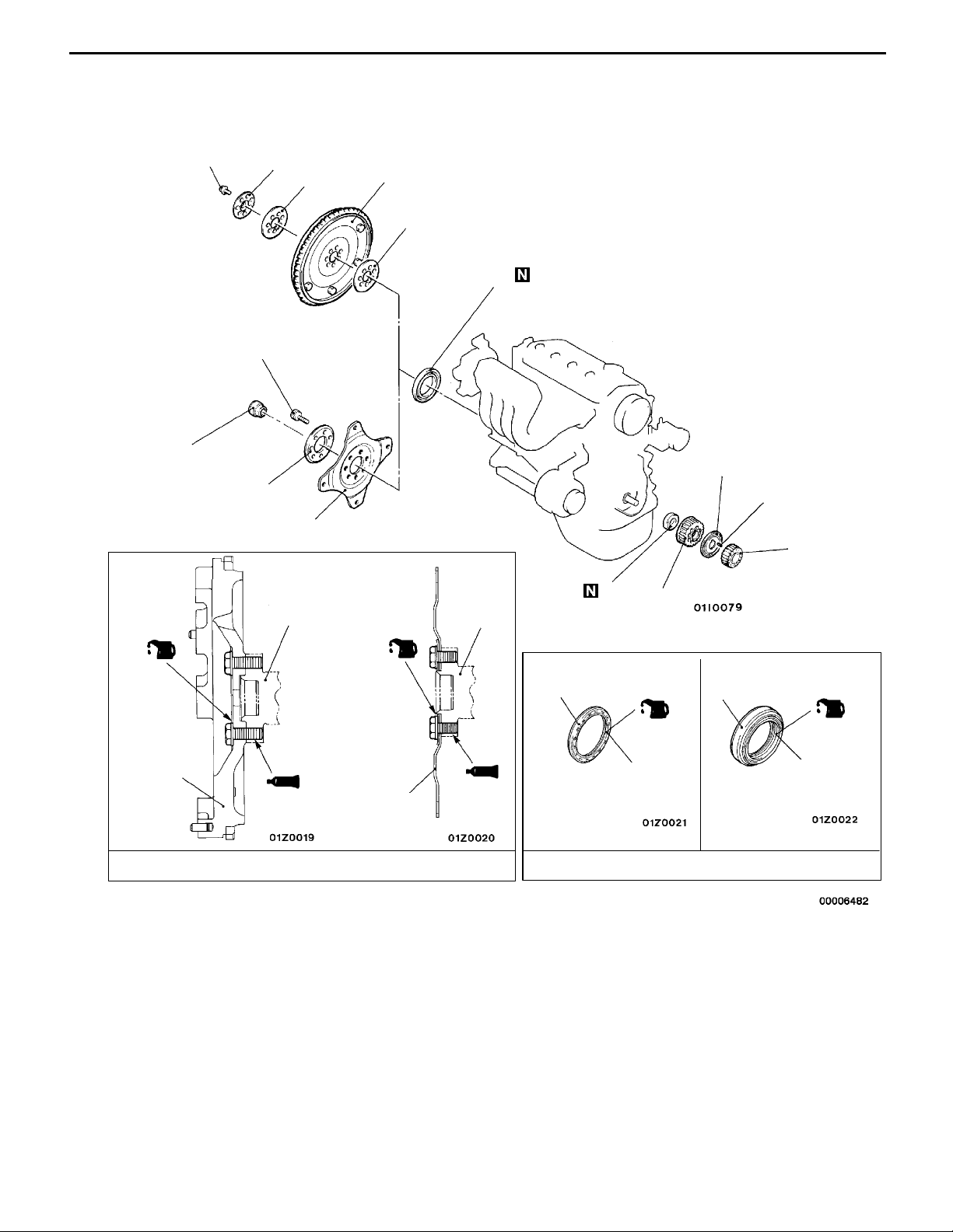
CRANKSHAFT OIL SEAL
REMOVAL AND INSTALLATION
Crankshaft Oil Seal
11C-21
127 - 137 Nm
<M/T>
<M/T>
7
8
9
11
12
127 - 137 Nm
<A/T>
6
2
8
4
10
1
<A/T>
Crankshaft
Crankshaft
5
3
(Engine oil:
(Engine oil:
bolt washer surface)
bolt washer
surface)
9
10
Sealant: 3M Stud locking 4170 or equivalent
Crankshaft front oil seal removal
steps
D
Timing belt (Refer to P.11C-27.)
D
Timing belt B (Refer to P.11C-31.)
D
Crank angle sensor
(Refer to GROUP 16.)
1. Crankshaft sprocket
2. Flange
3. Crankshaft sprocket B
"CA
4. Key
5. Crankshaft front oil seal
12
Lip section
Engine oil
Crankshaft rear oil seal removal
steps
D
AA"D
AB""BA
AB""BA
AB""BA
AB""BA
AB""BA
"AA
Oil pan (Refer to P.11C-19.)
Transmission assembly
D
Clutch cover and disc <M/T>
6. Crankshaft bushing <A/T>
7. Plate <M/T>
8. Adapter plate
9. Flywheel <M/T>
10. Drive plate <A/T>
11. Adapter plate <M/T>
12. Crankshaft rear oil seal
5
Lip section
Page 29
11C-22
ENGINE <4G6-MPI> -
Crankshaft Oil Seal
<M/T>
Flywheel
Bolt
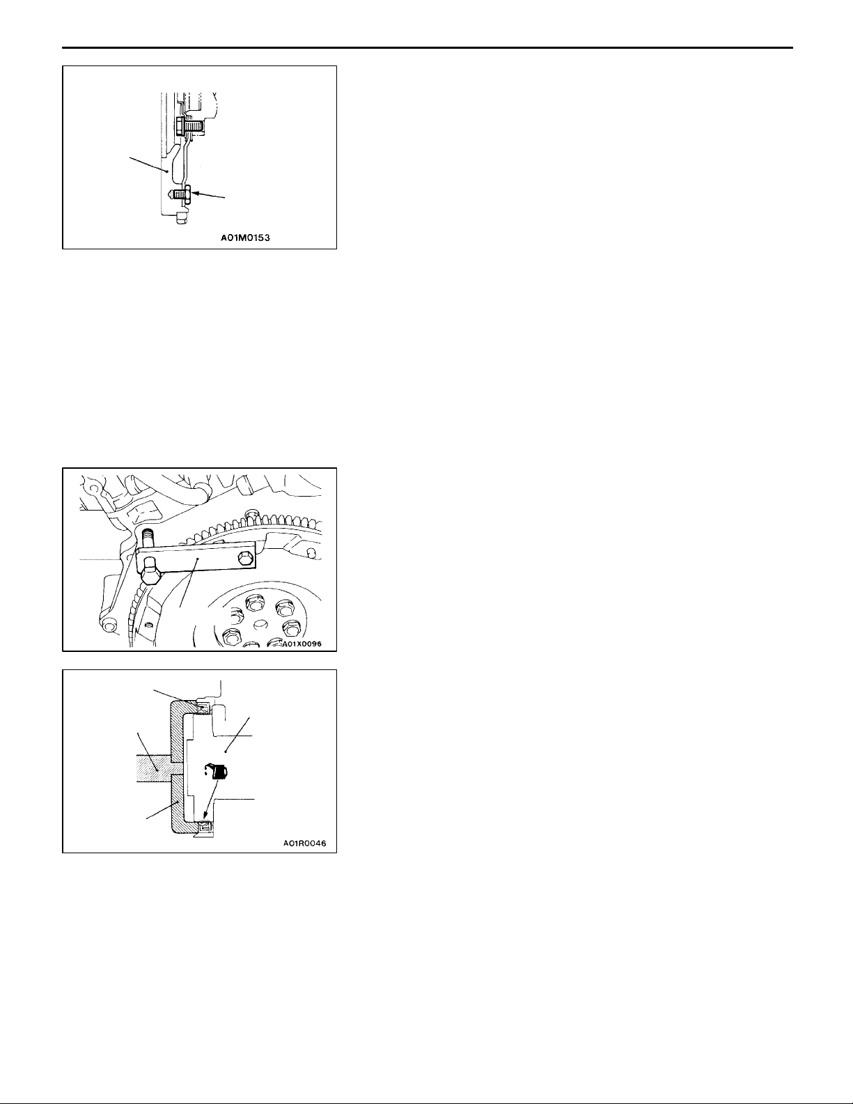
REMOVAL SERVICE POINTS
AA"
<M/T>:
Refer to ’99 SPACE RUNNER/SPACE WAGON Workshop
Manual (Pub. No. PWDE9803) GROUP 22.
Caution
Do not remove the flywheel mounting bolt shown by the
arrow. If this bolt Is removed, the flywheel will become
out of balance and damaged.
<A/T>:
Refer to ’99 SPACE RUNNER/SPACE WAGON Workshop
Manual (Pub. No. PWDE9803) GROUP 23.
AB"
Use the special tool to secure the flywheel or drive plate,
and remove the bolts.
TRANSMISSION ASSEMBLY REMOVAL
PLATE <M/T>/ADAPTER PLATE/FLYWHEEL
<M/T>/DRIVE PLATE <A/T> REMOVAL
Crankshaft
rear oil seal
MD990938
MD998776
MD998781
Crankshaft
INSTALLATION SERVICE POINTS
"AA
1. Apply a small mount of engine oil to the entire
2. Install the oil seal by tapping it as far as the chamfered
"BA
1. Clean off all sealant, oil and other substances which are
CRANKSHAFT REAR OIL SEAL INSTALLATION
circumference of the oil seal lip.
position of the oil seal case as shown in the illustration.
DRIVE PLATE <A/T>/FLYWHEEL <M/T>/ADAPTER
PLATE/PLATE <M/T> INSTALLATION
adhering to the threaded bolts, crankshaft thread holes
and the flywheel or drive plate.
Page 30

ENGINE <4G6-MPI> -
2. Apply oil to the bearing surface of the flywheel or drive
plate bolts.
3. Apply oil to the crankshaft thread holes.
4. Apply sealant to the threaded mounting holes.
Specified sealant: 3M Stud locking 4170 or equivalent
5. Use the special tool to hold the flywheel or drive plate
in the same manner as removal, and install the bolt.
Crankshaft Oil Seal
11C-23
"CA
1. Apply a small amount of engine oil to the entire
2. Press-fit the oil seal unit it is flush with the oil seal case.
CRANKSHAFT FRONT OIL SEAL INSTALLATION
circumference of the oil seal lip.
Page 31

11C-24
ENGINE <4G6-MPI> -
CYLINDER HEAD GASKET
REMOVAL AND INSTALLATION
Cylinder Head Gasket
Pre-removal and Post-installation Operation
D Fuel Discharge Prevention (Refer to GROUP 13D
- On-vehicle Service.) <Pre-removal only>
D Engine Coolant Draining and Supplying
D Engine Oil Draining and Supplying
1
78 Nm®0Nm®20 Nm®+90
_ ®
+90
9
(Engine oil)
3
10
D Intake Manifold Removal and Installation (Refer to
GROUP 15.)
D Thermostat Case Assembly Removal and Installation
(Refer to GROUP 14 - Water Hose and Pipe.)
D Timing Belt Removal and Installation (Refer to
P.11C-27.)
10 Nm
2
1
_
7
8
3.4 Nm
AA"
11
Removal steps
1. Ignition coil connector
2. Ignition coil assembly
3. Camshaft position sensor connector
4. Power steering oil pump and
bracket assembly
5. Front exhaust pipe connection
4
34 Nm
AB""BA
"AA
49 Nm
6
5
44 Nm
6. Engine oil level gauge
7. Breather hose
8. Rocker cover
9. Cylinder head bolt
10. Cylinder head assembly
11. Cylinder head gasket
Page 32

ENGINE <4G6-MPI> -
REMOVAL SERVICE POINTS
AA"
Remove the power steering oil pump and bracket assembly
from the engine with the hose attached.
NOTE
Place the removed power steering oil pump in a place where
it will not be a hindrance when removing and installing the
cylinder head assembly, and tie it with a cord.
Cylinder Head Gasket
11C-25
POWER STEERING OIL PUMP AND BRACKET
ASSEMBLY REMOVAL
Intake side
351082
17964
Exhaust side
A
Burred side
Head bolt
washer
Cylinder
head
Front of engine
Head bolt
(Engine
oil)
AB"
CYLINDER HEAD BOLT REMOVAL
Loosen the bolts in 2 or 3 steps in order of the numbers
shown in the illustration, and remove the cylinder head
assembly.
Caution
Because the plug guides cannot be replaced by
themselves, be careful not to damage or deform the plug
guides when removing the cylinder head bolts.
INSTALLATION SERVICE POINTS
"AA
1. Wipe off all oil an d grease from the gasket mounting
2. Install so that the shapes of the cylinder head holes match
"BA
1. When installing the cylinder head bolts, the length below
2. The head bolt washer should be installed with the burred
3. Apply a small amount of engine oil to the thread section
CYLINDER HEAD GASKET INSTALLATION
surface.
the shapes of the respective cylinder head gasket holes.
CYLINDER HEAD BOLT INSTALLATION
the head of the bolts should be within the limit.
If it is outside the limit, replace t h e bolts.
Limit (A): 99.4 mm
side caused by tapping out facing upwards.
and the washer of the cylinder head bolt.
Page 33

11C-26
ENGINE <4G6-MPI> -
Cylinder Head Gasket
Intake side
86139
104257
Exhaust side
Step 4
90
_
Painted mark
Front of engine
Step 5
Painted mark
90
4. Tighten the bolts by the following procedure.
Step Operation Remarks
1 Tighten to 78 Nm. Carry out in the order
shown in the illustration.
2 Fully loosen. Carry out in the reverse
order of that shown in the
illustration.
3 Tighten to 20 Nm. Carry out in the order
shown in the illustration.
4 Tighten 90_of a turn. In the order shown in the
illustration. Mark the head
of the cylinder head bolt
_
5 Tighten 90_of a turn. In the order shown in the
and cylinder head by paint.
illustration. Check that the
painted mark of the head
bolt is lined up with that of
the cylinder head.
Caution
1. Always make a tightening angle just 90_. If it is less
than 90_, the head bolt will be loosened.
2. If it is more than 90_, remove the head bolt and repeat
the procedure from step 1.
"CA
HIGH-PRESSURE FUEL HOSE INSTALLATION
1. Apply a small amount of new engine oil to the O-ring.
Caution
Do not let any engine oil get into the delivery pipe.
2. While turning the high-pressure fuel hose to the right
and left, install the delivery pipe, while being careful not
to damage the O-ring. After installing, check that the hose
turns smoothly.
3. If the hose does not turn smoothly, the O-ring is probably
being clamped. Disconnect the high-pressure fuel hose
and check the O-ring for damage. After this, re-insert
the delivery pipe and check that the hose turns smoothly.
Page 34

ENGINE <4G6-MPI> -
TIMING BELT
REMOVAL AND INSTALLATION
Pre-removal and Post-installation Operation
D Crankshaft Pulley Removal and Installation (Refer
to P.11C-15.)
D Engine Mount Bracket Removal and Installation
Timing Belt
3
11C-27
10 - 12 Nm
"CAD
AA""BA
"AA
1
5
9Nm
Removal steps
1. Timing belt upper cover
2. Timing belt lower cover
Timing belt tension adjustment
3. Timing belt
4. T ension pulley
5. Auto tensioner
48 Nm
4
24 Nm
2
Page 35

11C-28
ENGINE <4G6-MPI> -
Timing Belt
Timing mark (Top
of cylinder head)
Timing mark
Timing mark
Crankshaft
sprocket
B
A
Auto tensioner
Timing mark
98 - 196N
Camshaft sprocket
Timing mark
Oil pump
sprocket
Centre bolt
Movement
Push rod
REMOVAL SERVICE POINT
AA"
1. Turn the crankshaft clockwise (right turn) to align each
2. Loosen the tension pulley centre bolt.
3. Move the tension pulley to the water pump side, and
TIMING BELT REMOVAL
timing mark and to set the No. 1 cylinder at compression
top dead centre.
Caution
The crankshaft should always be turned only
clockwise.
then remove the timing belt.
Caution
If the timing belt is to be re-used, use chalk to mark
(on its flat side) an arrow indicating the clockwise
direction.
INSTALLATION SERVICE POINTS
"AA
1. Apply 98 - 196 N force to the auto tensioner by pressing
2. If it is out of the standard value, replace the auto tensioner.
AUTO TENSIONER INSTALLATION
it against a metal (cylinder block, etc.), and measure the
movement of the push rod.
Standard value: Within 1 mm
A: Length when it is free (not pressed)
B: Length when it is pressed
A - B: Movement
AB
3. Use a press or vice to gently compress the auto tensioner
push rod until pin hole A of the push rod and pin hole
B of the tensioner cylinder are aligned.
Caution
If the compression speed is too fast, the rod may
become damaged, so be sure to carry out this
operation slowly.
Page 36

ENGINE <4G6-MPI> -
Timing Belt
11C-29
Timing mark (Top
of cylinder head)
Timing mark
Timing mark
Crankshaft
sprocket
Plug
Set pin
Timing mark
Camshaft sprocket
Timing mark
60 mm or
more
Counterbalance
shaft
Oil pump
sprocket
Screwdriver
Cylinder
block
8mm
4. Once the holes are aligned, insert the set pin.
NOTE
When replacing the auto tensioner with a new part, the
pin will be in the auto tensioner.
5. Install the auto tensioner to the engine.
"BA
TIMING BELT INSTALLATION
1. Align the timing marks on the camshaft sprocket,
crankshaft sprocket and oil pump sprocket.
2. After aligning the timing mark on the oil pump sprocket,
remove the cylinder block plug and insert a Phillips
screwdriver with a diameter of 8 mm, and check to be
sure that the screwdriver goes in 60 mm or more. If
the screwdriver will only go in 20 - 25 mm before striking
the counterbalance shaft, turn the sprocket once, realign
the timing mark and check that the screwdriver goes in
60 mm or more. The screwdriver should not be taken
out until the timing belt is installed.
Fixing bolt
Pin hole
Belt tension side
Belt tension side
3. Install the belt to the crankshaft sprocket, oil pump
sprocket and camshaft sprocket in that order, so that
there is no slackness in the belt tension.
Caution
If the timing belt is re-used, install so that the arrow
marked on it at time of removal is pointing in the
clockwise direction.
4. Set the tension pulley so that the pin holes are at the
top, press the tension pulley lightly against the timing
belt, and then provisionally tighten the fixing bolt.
5. Adjust the timing belt tension.
Page 37

11C-30
ENGINE <4G6-MPI> -
Timing Belt
50 Nm
MD998767
A
Auto tensioner
Tension
direction
"CA
TIMING BELT TENSION ADJUSTMENT
1. After turning the crankshaft 1/4 of a revolution in the
anticlockwise direction, turn it in the clockwise direction
until the timing marks are aligned.
2. Loosen the tension pulley fixing bolt, and then use the
special tool and a torque wrench to tighten the fixing
bolt to the specified torque while applying tension to the
timing belt.
Standard value: 3.5 Nm <Timing belt tension torque>
Caution
When tightening the fixing bolt, make sure that the
tension pulley does not turn with the bolt.
3. Turn the crankshaft two revolutions in the clockwise
direction so that the timing marks are aligned. After leaving
it for 15 minutes, measure the amount of protrusion of
the auto tensioner.
Standard value (A): 3.8 - 4.5 mm
4. If the amount of protrusion is outside the standard value,
repeat the operation in steps (1) to (3).
5. Check again to be sure that the timing marks of each
sprocket are aligned.
Page 38

ENGINE <4G6-MPI> -
TIMING BELT B
REMOVAL AND INSTALLATION
1
19 Nm
4
Timing Belt B
11C-31
5
Removal steps
1. Timing belt (Refer to P.11C-27.)
AA""CA 2. Crankshaft sprocket
"BA 3. Flange
Crankshaft
sprocket
MD998719 or MD998754
MB990767
2
108 - 127 Nm
REMOVAL SERVICE POINTS
AA"
3
4. Timing belt B tensioner
AB""AA 5. Timing belt B
CRANKSHAFT SPROCKET REMOVAL
AB"
TIMING BELT B REMOVAL
Caution
If timing belt “B” is to be re-used, use chalk to mark
it with an arrow on its flat side indicating the turning
direction (to the right).
Page 39

11C-32
ENGINE <4G6-MPI> -
Timing Belt B
Counterbalance shaft sprocket
Timing
marks
Crankshaft
sprocket B
Centre of
tensioner
pulley
Centre of installation
bolt
Shaft
Belt tension side
Timing marks
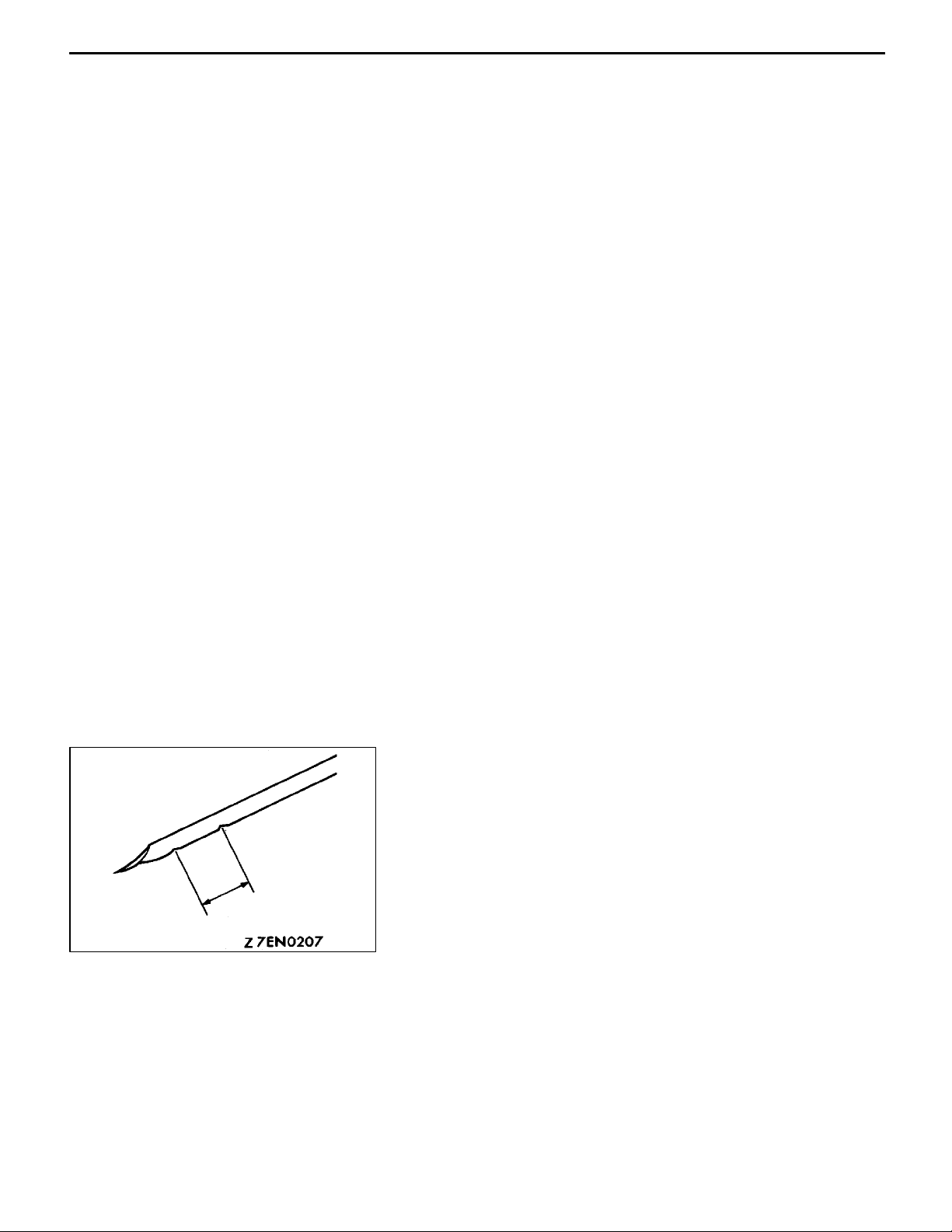
INSTALLATION SERVICE POINTS
"AA
1. Install timing belt “B” by the following procedure.
2. Adjust the tension of timing belt “B” by the following
TIMING BELT B INSTALLATION, ADJUSTMENT
(1) Ensure that crankshaft sprocket “B” timing mark and
the counterbalance shaft sprocket timing mark are
aligned.
(2) Fit timing belt “B” over crankshaft sprocket “B” an d
the counterbalance shaft sprocket. Ensure that there
is no slack in the belt.
procedure.
(1) Temporarily fix the timing belt “B” tensioner such that
the centre of the tensioner pulley is to the left a nd
above the centre of the installation bolt, and
temporarily attach the tensioner pulley so that the
flange is toward the front of the engine.
(2) Holding the timing belt “B” tensioner up with your
finger in th e direction of the arrow, place pressure
on the timing belt so that the tension side of the
belt is taut. Now tighten the bolt to fix the tensioner.
Caution
When tightening the bolt, ensure that the tensioner
pulley shaft does not rotate with the bolt. Allowing
it to rotate with the bolt can cause excessive
tension on the belt.
Centre of
tensioner
pulley
Centre of
installation
bolt
Crankshaft
sprocket
A
Flange
Crankshaft
Crankshaft
sprocket “B”
3. To ensure that the tension is correct, depress the belt
(point A) with a finger. I f not, adjust.
Standard value: 5 - 7 mm
"BA
FLANGE INSTALLATION
When installing, make sure the direction is correct. See figure.
Page 40

ENGINE <4G6-MPI> -
Timing Belt B
11C-33
Crankshaft
sprocket
MD998719 or MD998754
MB990767
"CA
CRANKSHAFT SPROCKET INSTALLATION
NOTE
Apply the minimum amount of engine oil to the bearing surface
and thread of the crankshaft bolt.
Page 41

11C-34
ENGINE <4G6-MPI> -
Engine Assembly
ENGINE ASSEMBLY
REMOVAL AND INSTALLATION
Caution
Mounting locations marked by * should be provisionally tightened, and then fully tightened after
placing the vehicle horizontally and loading the full weight of the engine on the vehicle body.
Pre-removal and Post-installation Operation
D Fuel Discharge Prevention (Refer to GROUP 13D
- On-vehicle Service.) <Pre-removal only>
D Engine Cover Removal and Installation
D Under Cover Removal and Installation
D Engine Coolant Draining and Supplying
3
5Nm 39Nm
9
13
12
4
2
67 Nm
11
16
57 Nm
10
16
D Hood Removal and Installation
D Transmission Assembly Removal and Installation
D Drive Belt Tension Adjustment (Refer to P.11C-6.)
<Post-installation only>
D Accelerator Cable Adjustment <Post-installation only>
2
5
17
6
39 Nm
8
7
1
AA"
AB"
15
14
98 - 118 Nm*
Removal steps
1. Drive belt (Power steering and
A/C)
2. Engine harness connector
3. Earth cable connection
4. Accelerator cable connection
5. Alternator connector
6. Power steering hose clamp
7. A/C compressor
8. Power steering oil pump
9. Vacuum hose connection
AC""CA
"BA
AD""AA
10. Brake booster vacuum hose
connection
11. Heater hose connection
12. Fuel return hose connection
13. Fuel pressure hose connection
14. Power steering oil reservoir
15. Engine mount bracket
16. Engine mount stopper
17. Engine assembly
Page 42

ENGINE <4G6-MPI> -
REMOVAL SERVICE POINTS
AA"
Disconnect the A/C compressor connector and remove the
compressor from the compressor bracket with the hose still
attached.
NOTE
Place the removed A/C compressor where it will not be a
hindrance when removing and installing the engine assembly,
and tie it with a cord.
A/C COMPRESSOR REMOVAL
Engine Assembly
11C-35
MB991453
MZ203827
AB"
Remove the power steering oil pump and bracket assembly
from the engine with the hose attached.
NOTE
Place the removed power steering oil pump in a place where
it will not be a hindrance when removing and installing the
engine assembly, and tie it with a cord.
AC"
1. Support the engine with a garage jack.
2. Remove the special tool which was attached when the
3. Hold the engine assembly with a chain block or similar
4. Place a garage jack against the engine oil pan with a
AD"
After checking that all cables, hoses and harness connectors,
etc., are disconnected from the engine, lower the chain block
slowly to remove the engine assembly downward from the
engine compartment.
POWER STEERING OIL PUMP REMOVAL
ENGINE MOUNT BRACKET REMOVAL
transmission assembly was removed.
tool.
piece of wood in between, jack up the engine so that
the weight of the engine is no longer being applied to
the engine mount bracket, and then remove the engine
mount bracket.
ENGINE ASSEMBLY REMOVAL
Page 43

11C-36
ENGINE <4G6-MPI> -
INSTALLATION SERVICE POINTS
"AA
Install the engine assembly, checking that the cables, hoses,
and harness connectors are not clamped.
ENGINE ASSEMBLY INSTALLATION
Engine Assembly
Engine
mount
stopper
Engine mount bracket
Engine side
Arrow
"BA
ENGINE MOUNT STOPPER INSTALLATION
Clamp the engine mount stopper so that the arrow points
in the direction as shown in the diagram.
"CA
ENGINE MOUNT BRACKET INSTALLATION
1. Place a garage jack against the engine oil pan with a
piece of wood in between, and install the engine mount
bracket while adjusting the position of the engine.
2. Support the engine with the garage jack.
3. Remove the chain block and support the engine assembly
with the special tool.
Page 44

FUEL
CONTENTS
GASOLINE DIRECT INJECTION (GDI) 13A..................................
MULTIPOINT FUEL INJECTION (MPI) <4G6> 13D............................
13A-1
Page 45

13A-2
GASOLINE
DIRECT
INJECTION (GDI)
CONTENTS
GENERAL 3.................................
Outline of Change 3...........................
SERVICE SPECIFICATIONS 3.................
TROUBLESHOOTING 3.......................
ON-VEHICLE SERVICE 11....................
Accelerator Pedal Position Switch and Accelerator
Pedal Position Sensor Adjustment 11............
Accelerator Pedal Position Sensor Inspection 11..
Accelerator Pedal Position Switch Inspection 12..
FUEL PUMP (HIGH PRESSURE) AND FUEL
PRESSURE REGULATOR
(HIGH PRESSURE) 14.......................
INJECTOR 18...............................
Page 46

GDI <4G6> -
General/Service Specification/Troubleshooting
13A-3
GENERAL
OUTLINE OF CHANGES
The following service procedures for items which are different from before have been established to
correspond to the addition of vehicles with 4G6-GDI engine.
Other service procedures are the same as before.
D An integrated-type accelerator pedal position sensor has been adopted.
D A GDI ECO indication lamp has been adopted.
D The fuel feed pipe and fuel return pipe shapes have been changed.
SERVICE SPECIFICATIONS
Items Standard value
Adjustment voltages (1) and (2) of accelrator pedal position sensor V 0.5 - 0.9
Resistance (1) and (2) of accelerator pedal position sensor k
W
3.5 - 6.5
TROUBLESHOOTING
INSPECTION CHART FOR DIAGNOSIS CODES
Diagnosis code Nos. 77 and 78 have been changed in line with the adoption of an integrated-type accelerator
pedal position sensor. Other items are the same as before.
Code No. Diagnosis item Reference page
77 Accelerator pedal position sensor (2nd channel) system 13A - 4
78 Accelerator pedal position sensor (1st channel) system 13A-5
Page 47

13A-4
GDI <4G6> -
Troubleshooting
INSPECTION PROCEDURE FOR DIAGNOSIS CODES
Code No.77 Accelerator pedal position sensor (2nd
channel) system
Range of check
D Accelerator pedal position sensor (1st channel) system is normal.
D Communication between the engine-ECU and throttle valve controller is normal.
Set conditions
D Output voltage of accelerator position sensor (2nd channel) system is 0.2 V or
less for one second.
or
D Output voltage of the accelerator pedal position sensor (1st channel) is 2.5 V
or less, and output voltage of the accelerator pedal position sensor (2nd channel)
is 4.5 V or more for one second.
or
D Difference between the accelerator pedal position sensor output voltages (1st
and 2nd channels) exceeds 1.0 V (i.e. when the throttle valve opening angle changes
slightly).
Check the accelerator pedal position
sensor (2nd channel). (Refer to P.13A-
11.)
OK
Measure at accelerator pedal position
sensor connector A-103.
D Disconnect the connector, and
measure at the harness side.
D Voltage between terminal 8 and
earth
(Ignition switch: ON)
OK:
earth
OK:
4.8 - 5.2 V
Continuity
OK
D Continuity between terminal 7 and
NG
NG
Replace the accelerator pedal position
sensor assembly.
Check the following connectors:
A-27, B-50
OK
Check trouble symptom.
Probable cause
D Malfunction of the accelerator pedal position sensor
(2nd channel)
D Open circuit or short-circuited harness wire in the
accelerator pedal position sensor (2nd channel)
system, or poor connector contact
D Malfunction of the throttle valve controller
D Malfunction of the engine-ECU
NG
NG
Repair
Check the harness wire between the
throttle valve controller and the accelerator pedal position sensor (2nd channel).
OK
Replace the throttle valve controller.
NG
Repair
Measure at throttle valve controller connector B-50.
D Connect the connector.
D Voltage between terminal 20 and
earth (Ignition switch: ON)
OK:
0.3 - 1.0 V
(Accelerator pedal: fully released)
4.2 - 5.5 V
(Accelerator pedal: fully depressed)
OK
MUT-IIData list
78 Accelerator pedal position sensor
(1st channel). (Refer to P.13A-9.)
OK
Replace the throttle valve controller.
NG
NG
Check the following connectors:
A-27, A-103
OK
Check trouble symptom.
Check the accelerator pedal position
sensor (1st channel) system. (Refer to
P.13A-5, INSPECTION PROCEDURE
FOR DIAGNOSIS CODE 78.)
NG
NG
Repair
Check the harness wire between the
accelerator pedal position sensor (2nd
channel) and throttle valve controller.
OK
Adjust the accelerator pedal position
sensor. (Refer to P.13A-11.)
Check trouble symptom.
NG
Replace the throttle valve controller.
NG
Repair
Page 48

GDI <4G6> -
Troubleshooting
13A-5
Code No.78 Accelerator pedal position sensor (1st
channel) system
Range of check
D Accelerator pedal position sensor (2nd channel) system is normal.
D Communication between the engine-ECU and throttle valve controller is normal.
Set conditions
D Output voltage of accelerator position sensor (1st channel) system is 0.2 V or
less for one second.
or
D Output voltage of the accelerator pedal position sensor (2nd channel) is 2.5 V
or less, and (1st channel) output voltage of the accelerator pedal position sensor
is 4.5 V or more for one second.
or
D Difference between the accelerator pedal position sensor (1st and 2nd channels)
output voltages exceeds 1.0 V (i.e. when the throttle valve opening angle changes
slightly).
or
D Although the accelerator pedal position switch is on, 1st-channel output voltage
of the accelerator pedal position sensor exceeds 1.1 V for one second.
MUT-IIData list
26 Accelerator pedal position switch
(P.13A-9.)
OK
Check the accelerator pedal position
sensor (1st channel). (Refer to P.13A-
11.)
OK
Measure at the accelerator pedal position sensor connector A-103.
D Disconnect the connector, and
measure at the harness side.
D Voltage between terminal 2 and
earth (Ignition switch: ON)
OK:
D Continuity between terminal 1 and
Measure at the engine-ECU B-51.
D Connect the connector.
D Voltage between terminal 87 and
MUT-IIData list
78 Accelerator pedal position sensor
(2nd channel). (Refer to P.13A-9.)
Replace the engine-ECU.
4.8 - 5.2 V
earth
OK:
Continuity
OK
earth
(Ignition switch: ON)
OK:
0.3 - 1.0 V
(Accelerator pedal: fully released)
4.2 - 5.5 V
(Accelerator pedal: fully depressed)
OK
OK
NG
NG
NG
NG
NG
Check the accelerator pedal position
switch system. (Refer to P.13A-7, INSPECTION PROCEDURE 27.)
Replace the accelerator pedal position
sensor assembly.
Check the following connectors:
A-27, B-51
OK
Check trouble symptom.
Check the following connectors:
A-27, A-103
OK
Check trouble symptom.
Check the accelerator pedal position
sensor (2nd channel) system. (Refer
to P.13A-4, INSPECTION PROCEDURE FOR DIAGNOSIS CODE 77.)
Probable cause
D Malfunction of the accelerator pedal position sensor
(1st channel)
D Open circuit or short-circuited harness wire in the
accelerator pedal position sensor (1st channel) system,
or poor connector contact
D ON-seizure of the accelerator pedal position switch
D Malfunction of the throttle valve controller
D Malfunction of the engine-ECU
NG
NG
NG
NG
Repair
Check the harness wire between the
accelerator pedal position sensor (1st
channel) and engine-ECU.
OK
Replace the engine-ECU.
Repair
Check the harness wire between the
accelerator pedal position sensor (1st
channel) and engine-ECU.
OK
Adjust the accelerator pedal position
sensor. (Refer to P.13A-11.)
Check trouble symptom.
NG
Replace the engine-ECU.
NG
Repair
NG
Repair
Page 49

13A-6
GDI <4G6> -
Troubleshooting
INSPECTION CHART FOR TROUBLE SYMPTOMS
Inspection procedure No. 27 has been changed in line with the adoption of an integrated-type accelerator
pedal position sensor. Inspection procedure Nos. 36 and 37 have been added in line with the adoption
of a GDI indication lamp. Other items are the same as before.
Trouble symptom Inspection
procedure No.
GDI ECO indication The GDI ECO indication lamp does not illuminate. 36 13A- 8
lamp system
The GDI ECO indication lamp remains on (does not
extinguish).
37 13A-8
Reference page
Page 50

GDI <4G6> -
GDI <4G6> -
Troubleshooting
Troubleshooting
INSPECTION PROCEDURE FOR TROUBLE SYMPTOMS
INSPECTION PROCEDURE 2 7
13A-7
Accelerator pedal position switch system
The accelerator pedal position switch detects that the accelerator pedal is fully closed,
and sends a signal to the engine-ECU. The engine-ECU controls idle speed, based
on this signal.
Check the accelerator pedal position switch. (Refer to P.13A-11.)
OK
Measure at accelerator pedal position sensor connector A-103.
D Disconnect the connector, and measure at the harness side.
D Voltage between terminal 4 and earth
(Ignition switch: ON)
OK:
OK:
4 V or more
Continuity
OK
A-103
OK
D Continuity between terminal 5 and earth
Check the following connector:
Check trouble symptom.
NG
NG
NG
NG
Replace the accelerator pedal position sensor assembly.
Check the following connectors:
Check trouble symptom.
Check the harness wire between the engine-ECU and accelerator
pedal position sensor 1 (1st channel).
Repair
Replace the engine-ECU.
Probable cause
D Maladjustment of the accelerator cable
D Maladjustment of the accelerator pedal position switch
D Open circuit or short-circuited harness wire in the
accelerator pedal position switch system, or poor
connector contact
D Malfunction of the engine-ECU
A-27, B-51, B-52
OK
NG
OK
NG
Repair
NG
Repair
Page 51

13A-8
INSPECTION PROCEDURE 3 6
GDI <4G6> -
Troubleshooting
The GDI ECO indication lamp does not illuminate.
If the GDI ECO indication lamp does not illuminate after turning on the ignition switch,
the causes listed in the right column are suspected.
MUT-IIData list
16 System voltage (Refer to P.13A-76*.)
OK
Measure at engine-ECU connector B-54.
D Disconnect the connector, measure at the harness side.
D Earth terminal 19
(Ignition switch: ON)
OK:
The GDI ECO indication lamp illuminates.
NG
Check a burned-out bulb.
OK
Measure at combination meter B-01.
D Disconnect the connector, measure at the harness side.
D Voltage between terminal 42 and earth
(Ignition switch: ON)
OK:
System voltage
NG
Check the GDI ECO indication lamp circuit, and repair if necessary.
NG
Replace
NG
OK
OK
Check the engine-ECU power supply and earth circuits system.
(Refer to P.13A-64*, INSPECTION PROCEDURE 23.)
Check the following connector:
Check trouble symptom.
Replace the engine-ECU.
Check the following connectors:
Check trouble symptom.
Probable cause
D Burned-out GDI ECO indication lamp bulb
D Open circuit or short -circuited harness wire in the
GDI ECO indication lamp circuit
D Malfunction of the engine-ECU
B-54
OK
NG
OK
NG
NG
Repair
B-02, B-15, B-54
NG
Repair
Check the harness wire between the combination meter and engineECU, and repair if necessary.
NOTE
*: Refer to the ’99 SPACE RUNNER/SPACE WAGON Workshop Manual (Pub. No. PWDE9803)
INSPECTION PROCEDURE 37
The GDI ECO indication lamp remains on (does not
Probable cause
extinguish).
If the GDI ECO indication lamp does not extinguish during high load operation, the
causes listed int right column are suspected.
Measure at combination meter connector B-02.
D Disconnect the connector, measure at the harness side.
D Disconnect the engine-ECU connector.
D Continuity between terminal 19 and earth.
OK:
No continuity
OK
Replace the engine-ECU.
NG
D Short circuit between the GDI ECO indication lamp
and engine-ECU
D Malfunction of the engine-ECU
Check the harness wire between the combination meter and engineECU, and repair if necessary.
Page 52

GDI <4G6> -
Troubleshooting
13A-9
DATA LIST REFERENCE TABLE
Caution
When shifting the select lever to D range, the brakes should be applied so that vehicle does not
move forward.
NOTE
1.*1: When the accelerator pedal position sensor (1st channel) output is 500 - 900 mV, the accelerator
pedal position switch should normally change from ON to OFF. If this does not happen, adjust the
accelerator pedal position sensor.
2.*2: Check if the difference in output between *2 and *3 is 4 V or more.
Item
No.
Check
items
Requirements Normal condition Inspection
procedure No.
Reference
page
26 Accelera-
tor pedal
position
switch
77 Accelera-
tor pedal
position
sensor
(2nd
channel)
78 Accelera-
tor pedal
position
sensor (1st
channel)*
ignition switch: ON
Depress and release
the accelerator pedal
several times)
ignition switch: ON
ignition switch: ON
1
Release the accelerator pedal.
Depress the accelerator pedal slightly.
Release the accelerator pedal.
Depress the accelerator pedal gradually.
Depress the accelerator pedal fully.
Release the accelerator pedal.
Depress the accelerator pedal gradually.
Depress the accelerator pedal fully.
CHECK AT THE ENGINE-ECU TERMINALS
TERMINAL VOLTAGE CHECK CHART
Engine-ECU Connector Terminal Arrangement
ON
OFF
300-1,000 mV*
Increases in response to the pedal
depression stroke.
4,200-5,500 mV*
300-1,000 mV*
Increases in response to the pedal
depression stroke.
4,200-5,500 mV*
2
2
Procedure
No. 27
Code No. 77 13A-4
3
Code No. 78 13A-5
3
13A-7
Terminal No. Check items Check requirements (engine condition) Normal condition
3 GDI ECO indication
lamp
57 Accelerator pedal Ignition switch:
position switch ON
81 Power supply to accel-
erator pedal position
sensor (1st channel)
87 Accelerator pedal Ignition switch:
position sensor
(1st channel)
Engine: idling 0-3 mV
Engine: When the accelerator pedal is suddenly
depressed while the engine is idling
Release the accelerator pedal. 0-1 V
Depress the accelerator pedal slightly. 4 V or more
Ignition switch: ON 4.5 - 5.5 V
Release the accelerator pedal. 0.3-1.0 V*
ON
Depress the accelerator pedal fully. 4.2- 5.5 V*
System voltage
1
2
NOTE
Check if the difference in output between *1 and *2 is 4 V or more.
Page 53

13A-10
GDI <4G6> -
Troubleshooting
Engine-ECU Connector Terminal Arrangement
Terminal No. Check items Standard value, Normal condition (Check require-
ments)
57-53 Accelerator pedal position switch Continuity (when the accelerator pedal is
released)
No continuity (when the accelerator pedal is
slightly depressed)
CHECK AT THE THROTTLE VALVE CONTROLLER TERMINALS
TERMINAL VOLTAGE CHECK CHART
Throttle Valve Controller Connector Terminal Arrangement
Terminal No. Check items Requirements Normal value
20 Accelerator pedal Ignition switch: ON Release the accelerator pedal. 0.3-1.0 V*
position sensor
(2nd channel)
Depress the accelerator pedal
fully.
4.5-5.5 V*
NOTE
Check if the difference in output between *1 and *2 is 4 V or more.
1
2
Page 54

GDI <4G6> -
ON-VEHICLE SERVICE
On-Vehicle Service
13A-11
Accelerator pedal
position sensor
Power steering
reservoir tank
Thickness
gauge
Accelerator pedal position sensor
Fully-closed stopper
Terminal (4)
Accelerator
lever
1. ACCELERATOR PEDAL POSITION SWITCH AND
ACCELERATOR PEDAL POSITION SENSOR
ADJUSTMENT
Caution
(1) The accelerator pedal position sensor is adjusted
correctly at the time of shipment from the factory,
and so it should not normally be moved.
(2) If adjustment does become necessary, use the
following procedure.
<When using t h e MUT-II>
(1) Connect the MUT-II to the diagnosis connector.
(2) Remove the two accelerator pedal position sensor
assembly mounting bolts, and then insert a thickness
gauge with a thickness of 0.60 mm in between the
accelerator lever and the fully-closed stopper.
(3) Turn the ignition switch to ON (without starting the engine).
(4) Loosen the accelerator pedal position sensor mounting
bolt, and then turn the accelerator pedal position sensor
anti-clockwise as far as it will go.
(5) Check that the idle switch turns on at this time.
(6) Turn the accelerator pedal position sensor clockwise until
the point is found where the idle switch turns off. Securely
tighten the accelerator pedal position sensor mounting
bolt at this point.
(7) Check that the accelerator pedal position sensor (1st
channel) output at this time is within the standard value
range.
Standard value: 0.5 - 0.9 V
Power steering
reservoir tank
Terminal (5)MB991658
Accelerator pedal
position sensor
(8) Turn the ignition switch to the LOCK (OFF) position.
(9) Remove the thickness gauge and then install the
accelerator pedal position sensor assembly.
(10)Remove th e MUT-II.
2. ACCELERATOR PEDAL POSITION SENSOR
INSPECTION
(1) Disconnect the accelerator pedal position sensor
connector.
Page 55

13A-12
GDI <4G6> -
(2) Measure the resistance between accelerator pedal
On-Vehicle Service
position sensor connector terminal (1) [accelerator pedal
position sensor (1st channel) earth] and terminal (2)
[accelerator pedal position sensor (1st channel) power
supply], and between terminal (7) [accelerator pedal
position sensor (2nd channel) earth] and terminal (8)
[accelerator pedal position sensor (2nd channel) power
supply].
Accelerator pedal position sensor
(1st channel) power supply
Accelerator
pedal position
sensor (1st
channel) earth
Accelerator pedal
position sensor (1st
channel) output
Accelerator pedal
position sensor (2nd
channel) earth
Accelerator pedal
position sensor
(2nd channel)
power supply
Accelerator pedal
position sensor (2nd
channel) output
Standard value: 0.5 - 0.9 k
W
(3) Measure the resistance between accelerator pedal
position sensor connector terminal (2) [accelerator pedal
position sensor (1st channel) power supply] and terminal
(3) [accelerator pedal position sensor (1st channel)
output], and between terminal (8) [accelerator pedal
position sensor (2nd channel) power supply] and terminal
(6) [accelerator pedal position sensor (2nd channel)
output].
Normal condition:
When accelerator pedal is
gently depressed
Changes comparatively
smoothly in proportion to the
accelerator pedal depression
amount
(4) If the measured values are outside the standard value
range, or if the resistance does not change smoothly,
replace the accelerator pedal position sensor.
NOTE
After replacement, adjust the accelerator pedal position
sensor. (Refer to P.13A - 11.)
Power steering
reservoir tank
Accelerator pedal
position switch
3. ACCELERATOR PEDAL POSITION SWITCH
INSPECTION
(1) Disconnect the accelerator pedal position sensor
connector.
(2) Check the continuity between accelerator pedal position
sensor connector terminal (4) (accelerator pedal position
switch) and terminal (5) (earth).
Normal condition:
Accelerator pedal Continuity
Depressed No continuity
Released Continuity
Page 56

Accelerator pedal
position switch
Earth
GDI <4G6> -
(3) If there is a malfunction, replace the accelerator pedal
On-Vehicle Service
position sensor.
NOTE
After replacement, adjust the accelerator pedal position
sensor. (Refer to P.13A - 11.)
13A-13
Page 57

13A-14
GDI <4G6> -
Fuel Pump (High Pressure) and
Fuel Pressure Regulator (High Pressure)
FUEL PUMP (HIGH PRESSURE) AND FUEL PRESSURE
REGULATOR (HIGH PRESSURE)
REMOVAL AND INSTALLATION
Pre-removal and Post-installation Operation
D Prevention of fuel discharge <before removal only>
D Engine Cover Removal and Installation
D Air Cleaner Assembly Removal and Installation
D Fuel Leak Check <after installation only>
19 Nm
24 Nm
1
9
19 Nm
1
10 - 13 Nm
10
16
6
7
8
11
9Nm
19 Nm
5
10 - 13 Nm
2
9Nm
20
3
11 Nm
4
18
17
19
15
5Nm
13
12
14
5Nm®17 Nm
9Nm
10 - 13 Nm
O-ring
3, 5,
12,
13,
16
Engine oil
Page 58

GDI <4G6> -
Fuel Pump (High Pressure) and
Fuel Pressure Regulator (High Pressure)
13A-15
Fuel pressure regulator (High
pressure) removal steps
1. Harness connector and clamp
4. Fuel return hose connection
"CA 5. Low-pressure fuel pipe
"CA 6. Fuel return pipe connection
7. Fuel pressure regulator (high pressure) assembly
AA""GA 8. Fuel pressure sensor
AA""GA 9. Flange
"FA 10. O-ring
"FA 11. Back-up ring
"BA 17. Back-up ring A
"BA 18. O-ring
"BA 19. Back-up ring
Fuel pump (High pressure) removal
steps
D Intake manifold removal (Refer to
GROUP 15.)
2. Fuel pipe clamp
"CA 3. Fuel feed pipe
"CA 5. Low-pressure fuel pipe
12. Fuel return hose connection
"EA 13. Fuel pressure hose connection
14. Fuel nipple assembly
"DA 15. Fuel pump (high pressure)
"BA 17. Back-up ring A
"BA 18. O-ring
"BA 19. Back-up ring
Pump camshaft case removal steps
7. Fuel pressure regulator (high pressure) assembly
"DA 15. Fuel pump (high pressure)
"CA 16. Fuel return pipe
"BA 17. Back-up ring A
"BA 18. O-ring
"BA 19. Back-up ring
"AA 20. Pump camshaft case
Flange
Fuel pressure
sensor
Mating marks
REMOVAL SERVICE POINT
AA"
If reusing the fuel pressure sensor, make the mating marks
on the sensor and the flange before removing the flange.
NOTE
The flange will be bent when it is installed to the engine.
Because of this, the sealing condition and installation condition
of the fuel pressure sensor will be maintained in good
condition. Therefore, the mating marks should be made in
order to install the flange in the original condition. If replacing
the fuel pressure sensor with a new part, the sensor and
flange should be replaced together.
FUEL PRESSURE SENSOR/FLANGE REMOVAL
Page 59

13A-16
Mating marks
GDI <4G6> -
GDI <4G6> -
O-ring
Fuel Pump (High Pressure) and
Fuel Pump (High Pressure) and
Fuel Pressure Regulator (High Pressure)
Fuel Pressure Regulator (High Pressure)
INSTALLATION SERVICE POINTS
"AA
1. Set the No.1 cylinder to the compression top dead centre
2. Align the mating mark on the housing of the pump
PUMP CAMSHAFT CASE ASSEMBLY
INSTALLATION
position.
camshaft case assembly with t h e mating mark on the
coupling, and then install the pump camshaft case
assembly to the engine.
Caution
Take care not to drop the O-ring.
Back-up ring A
Back-up ring B
Fuel
pump
(high
pressure)
"BA
BACK-UP RING B/O-RING/BACK-UP RING A
INSTALLATION
O-ring
Install the back-up rings and the O-ring as shown in th e
illustration.
Caution
1. Install the back-up ring B facing its cutaway surface
Cutaway
surface
toward the opposite side of the O-ring as shown in
the illustration.
2. Confirm the outer diameter of the back-up ring A.
Take care not to install the back-up ring for the fuel
pressure sensor by mistake. (Outer diameter of the
back-up ring A: 14.8 mm)
"CA
FUEL RETURN PIPE/LOW-PRESSURE FUEL
PIPE/FUEL FEED PIPE INSTALLATION
Apply a small amount of fresh engine oil to the O-ring.
Caution
Take care not to let any of the engine oil get inside the
fuel pump (high pressure), fuel pressure regulator (high
pressure) or the delivery pipe assembly.
"DA
FUEL PUMP (HIGH PRESSURE) INSTALLATION
Use a torque wrench with a precision of 0.5 Nm to tighten
the fuel pump mounting bolts according to the following
1
3
procedure.
1. Tighten the bolts to 5 Nm in the order shown in the
illustration.
2. Tighten the bolts to 17 Nm in the order shown in the
4
2
illustration. The overall difference in tightening torque
between the four bolts should be within 2 Nm.
Page 60

GDI <4G6> -
Fuel Pump (High Pressure) and
Fuel Pressure Regulator (High Pressure)
13A-17
Back-up ring
Fuel pressure sensor
O-ring
"EA
HIGH-PRESSURE FUEL HOSE INSTALLATION
1. Apply a small amount of fresh engine oil to the O-ring.
Caution
Take care not to let any of the engine oil get inside
the fuel pump (high pressure).
2. While being careful not to damage the O-ring, turn the
high-pressure fuel hose to the left and right and connect
it to the fuel pump (high pressure). After connecting, check
that the hose turns smoothly.
3. If the hose does not turn smoothly, the cause may be
that the O-ring is getting caught. Disconnect the hose,
check the O-ring for damage and re-connect the hose
to the fuel pump (high pressure) and then re-check.
"FA
BACK-UP RING/O-RING INSTALLATION
Install the back-up ring and the O-ring as shown in t h e
illustration.
Caution
Take care not to install the back-up ring A for the injector,
fuel feed pipe or fuel return pipe by mistake. (Outer
diameter of the back-up ring for the fuel pressure sensor:
15.1 mm)
"GA
FUEL PRESSURE SENSOR/FLANGE
INSTALLATION
1. Apply a small amount of fresh engine oil to the O-ring.
Caution
Take care not to let any of the engine oil get inside
the fuel pressure regulator (high pressure) assembly.
2. Align th e mating marks which were made at the time
of removal, and then install the fuel pressure sensor and
flange to the fuel pressure regulator (high pressure)
assembly.
Caution
If replacing the fuel pressure sensor with a new part,
the sensor and flange should be replaced together.
Page 61

13A-18
INJECTOR
REMOVAL AND INSTALLATION
GDI <4G6> -
Injector
Pre-removal and Post-installation Operation
D Prevention of fuel discharge <before removal only>
D Engine Cover Removal and Installation
D Air Cleaner Assembly Removal and Installation
9
D Intake Manifold Removal and Installation
D Fuel Leak Check <after installation only>
7
10
11
20 - 25 Nm
1
8
3
10 - 13 Nm
9Nm
11 Nm
Engine oil
AA"
14
16
"DA
"DA
"CA
"CA
"CA
18
17
16
14
15
12
2, 3
Removal steps
1. Fuel pipe clamp
2. Fuel feed pipe
3. Fuel return pipe
4. Back-up ring A
5. O-ring
6. Back-up ring B
7. Injector harness connector
8. Washer
9. Injector holder
13
O-ring
2
10 - 13 Nm
4
7
5
AB""BA
AB""BA
"AA
10. Delivery pipe assembly
11. Insulator
12. Fuel injector assembly
13. Back-up ring
14. O-ring
15. Back-up ring
16. Fuel injector
17. Gasket
18. Corrugated washer
Page 62

GDI <4G6> -
GDI <4G6> -
Injector
Injector
REMOVAL SERVICE POINTS
AA"
Caution
Disconnect the battery (-) cable from its terminal before
carrying out this operation.
INJECTOR HARNESS CONNECTOR
DISCONNECTION
13A-19
Corrugated washer
OK NG
f
×
AB"
Remove the delivery pipe assembly with the fuel injector
assembly still attached.
Caution
Be careful not to drop the fuel injector assembly when
removing the delivery pipe assembly.
DELIVERY PIPE ASSEMBLY/FUEL INJECTOR
ASSEMBLY REMOVAL
INSTALLATION SERVICE POINTS
"AA
Caution
1. The corrugated washer should always be replaced
2. There should be no scratches or foreign particles
3. Be careful not to mistake the corrugated washer
"BA
1. Apply a small amount of fresh engine oil to the O-ring.
CORRUGATED WASHER INSTALLATION
with a new part.
on the corrugated washer mounting surface of the
injector.
installation direction.
FUEL INJECTOR ASSEMBLY/DELIVERY PIPE
ASSEMBLY INSTALLATION
Caution
Take care not to let any of the engine oil get inside
the delivery pipe assembly.
2. While being careful not to damage the O-ring, turn the
fuel injector assembly to the left and right and connect
it to the delivery pipe assembly. After connecting, check
that the fuel injector turns smoothly.
3. If the fuel injector does not turn smoothly, the cause may
be that the O-ring is getting caught. Remove the fuel
injector, check the O-ring for damage and re-connect the
fuel injector to the delivery pipe assembly and then
re-check.
Page 63

13A-20
Mating
marks
Fuel injector
Delivery pipe
assembly
GDI <4G6> -
Injector
4. Align the mating marks on the delivery pipe assembly
and the fuel injector, and then install the delivery pipe
assembly with th e injector assembly still attached.
Back-up ring A
Back-up ring B
O-ring
Cutaway
surface
"CA
BACK-UP RING B/O-RING/BACK-UP RING A
INSTALLATION
Install the back-up rings and the O-ring as shown in th e
illustration.
Caution
1. Install the back-up ring B facing its cutaway surface
toward the opposite side of the O-ring as shown in
the illustration.
2. Confirm the outer diameter of the back-up ring A.
Take care not to install the back-up ring for the fuel
pressure sensor by mistake. (Outer diameter of the
back-up ring A: 14.8 mm)
"DA
FUEL RETURN PIPE/FUEL FEED PIPE
INSTALLATION
Apply a small amount of fresh engine oil to the O-ring.
Caution
Take care not to let any of the engine oil get inside the
fuel pump (high pressure), fuel pressure regulator (high
pressure) and delivery pipe.
Page 64

13D-1
MULTIPOINT FUEL
INJECTION
(4G6-MPI)
CONTENTS
MULTIPOINT FUEL INJECTION <4G6>
GENERAL 2...............................
Outline of Change 2.........................
GENERAL INFORMATION 2................
SERVICE SPECIFICATIONS 6..............
SEALANT 6...............................
SPECIAL TOOLS 7........................
TROUBLESHOOTING 8....................
ON-VEHICLE SERVICE 79................
Throttle Body (Throttle Valve Area)
Cleaning 79.................................
Idle Position Switch and Throttle Position
Sensor Adjustment 79.......................
Fixed SAS Adjustment 80....................
Basic Idle Speed Adjustment 81..............
Fuel Pressure Test 82.......................
Fuel Pump Connector Disconnection (How to
Reduce the Fuel Pressure) 84...............
Fuel Pump Operation Check 84..............
Component Location 85......................
Control Relay and Fuel Pump Relay Continuity
Check 86...................................
Intake Air Temperature Sensor Check 86......
Engine Coolant Temperature Sensor
Check 86...................................
Throttle Position Sensor Check 86............
Idle Position Switch Check 87................
Oxygen Sensor Check 88....................
Injector Check 89...........................
Idle Speed Control (ISC) Servo (Stepper
Motor) Check 91............................
Purge Control Solenoid Valve Check 91.......
EGR Control Solenoid Valve Check 91........
INJECTOR 92............................
THROTTLE BODY 94.....................
Page 65

13D-2
MPI -
General/General Information
MULTIPOINT FUEL INJECTION (MPI)
GENERAL
OUTLINE OF CHANGE
The following service procedures have been established in line with the addition of SPACE RUNNER
vehicles with 4G63-MPI engine.
GENERAL INFORMATION
The Multipoint Fuel Injection System consists
of sensors which detect the engine conditions,
the engine-ECU which controls the system
based on signals from these sensors, an d
actuators which operate under the control of
the engine-ECU. The engine-ECU carries out
FUEL INJECTION CONTROL
The injector drive times and injector timing are
controlled so that the optimum air/fuel mixture
is supplied to the engine to correspond to the
continually-changing engine operation conditions.
A single injector is mounted at the intake port
of each cylinder. Fuel is sent under pressure
from the fuel tank by the fuel pump, with the
pressure being regulated by the fuel pressure
regulator. The fuel thus regulated is distributed
to each of the injectors.
Fuel injection is normally carried out once for
each cylinder for every two rotations of the
crankshaft. The firing order is 1-3-4-2. This is
called sequential fuel injection.
IDLE AIR CONTROL
The idle speed is kept at the optimum speed
by controlling the amount of air that bypasses
the throttle valve in accordance with changes
in idling conditions and engine load during
idling. The engine-ECU drives the idle speed
control (ISC) motor to keep the engine running
at the pre-set idle target speed in accordance
with the engine coolant temperature and air
activities such as fuel injection control, idle
speed control and ignition timing control. In
addition, the engine-ECU is equipped with
several diagnosis modes which simplify
troubleshooting when a problem develops.
The engine-ECU provides a richer air/fuel
mixture by carrying out “open-loop” control
when the engine is cold or operating under
high load conditions in order to maintain engine
performance. In addition, when the engine is
warm or operating under normal conditions,
the engine-ECU controls the air/fuel mixture
by using the oxygen sensor signal to carry out
“closed-loop” control in order to obtain the
theoretical air/fuel mixture ratio that provides
the maximum cleaning performance from the
three way catalyst.
conditioner load. In addition, when the air
conditioner switch is turned off and o n while
the engine is idling, the ISC motor operates
to adjust the throttle valve bypass air amount
in accordance with the engine load conditions
in order to avoid fluctuations in the engine
speed.
IGNITION TIMING CONTROL
The power transistor located in the ignition
primary circuit turns ON a nd OFF to control
the primary current flow to the ignition coil. This
controls the ignition timing in order to provide
the optimum ignition timing with respect to the
engine operating conditions. The ignition timing
is determined by t h e engine-ECU from the
engine speed, intake air volume, engine coolant
temperature and atmospheric pressure.
Page 66

MPI -
SELF-DIAGNOSIS FUNCTION
D When an abnormality is detected in one
of the sensors or actuators related to
emission control, the engine warning lamp
(check engine lamp) illuminates as a
warning to the driver.
D When an abnormality is detected in one
of the sensors or actuators, a diagnosis
OTHER CONTROL FUNCTIONS
1. Fuel Pump Control
Turns the fuel pump relay ON so that current
is supplied to the fuel pump while the engine
is cranking or running.
2. A/C Relay Control
Turns the compressor clutch of the A/C
ON and OFF.
3. Fan Relay Control
The revolutions of the radiator fan and
GENERAL SPECIFICATIONS
General Information
code corresponding to the abnormality is
output.
D The RAM data inside the engine-ECU that
is related to the sensors and actuators can
be read by means of the MUT-II. In addition,
the actuators can be force-driven under
certain circumstances.
condenser fan are controlled in response
to the engine coolant temperature and
vehicle speed.
4. Purge Control Solenoid Valve Control
Refer to GROUP 17.
5. EGR Control Solenoid Valve Control
Refer to GROUP 17.
13D-3
Items Specifications
Throttle body Throttle bore mm 54
Throttle position sensor Variable resistor type
Idle speed control servo Stepper motor type (Stepper motor type by-pass air
control system with the air volume limiter)
Idle position switch Rotary contact type, within throttle position sensor
Engine-ECU Identification model
No.
Sensors Air flow sensor Karman vortex type
Barometric pressure sensor Semiconductor type
Intake air temperature sensor Thermistor type
Engine coolant temperature sensor Thermistor type
Oxygen sensor Zirconia type
Vehicle speed sensor Magnetic resistive element type
Except vehicles for
Germany
Vehicles for Germany E2T73676 <M/T>
E2T73675 <M/T>
E2T76371 <A/T>
E2T76372 <A/T>
Inhibitor switch Contact switch type
Camshaft position sensor Hall element type
Crank angle sensor Hall element type
Detonation sensor Piezoelectric type
Power steering fluid pressure switch Contact switch type
Page 67

13D-4
Items Specifications
Actuators Control relay type Contact switch type
Fuel pump relay type Contact switch type
Injector type and number Electromagnetic type, 4
Injector identification mark CDH275
EGR control solenoid valve Duty cycle type solenoid valve
Purge control solenoid valve ON/OFF type solenoid valve
MPI -
General Information
Fuel pressure
regulator
Regulator pressure kPa 329
Page 68

MPI -
General Information
MULTIPOINT FUEL INJECTION SYSTEM DIAGRAM
13D-5
*1 Oxygen sensor (front)
*2 Air flow sensor
*3 Intake air temperature sensor
*4 Throttle position sensor
*5 Idle position switch
*6 Camshaft position sensor
*7 Crank angle sensor
*8 Barometric pressure sensor
*9 Engine coolant temperature sensor
*10 Detonation sensor
*11 Oxygen sensor (rear)
D Power supply voltage
D Vehicle speed sensor
D A/C switch 1, 2
D Inhibitor switch
D Power steering fluid pressure switch
D Ignition switch - ST
D Ignition switch - IG
D Alternator FR terminal
D A/T-ECU
*6 Camshaft position sensor
Throttle position sensor
*4
Idle position switch
*5
Engine-ECU
<M/T> and
Engine-A/TECU <A/T>
z3
z1 Injector
z2 Purge control solenoid valve
z3 Idle speed control servo
z4 EGR control solenoid valve
D Fuel pump relay
D Control relay
D A/C power relay
D Engine warning lamp
D Diagnosis signal
D Ignition coil, power transistor
D Fan controller
D Alternator G terminal
Idle speed
control servo
*3 Intake air
temperature
sensor
*2, *8Air flow sensor (with
barometric pressure sensor)
Air cleaner
Air
Fuel pressure
regulator
To fuel
tank
PCV valve
From fuel
pump
z1
Injector
*9
*10 Detonation sensor
*1 Oxygen sensor (front)
*7 Crank angle sensor
EGR valve
Engine coolant
temperature sensor
Catalytic converter
z4
EGR control
solenoid valve
*11 Oxygen sensor (rear)
Throttle position sensor
(with idle position switch)
Canister
z2
Purge control
solenoid valve
Page 69

13D-6
MPI -
Service Specifications/Sealant
SERVICE SPECIFICATIONS
Items Specifications
Basic idle speed r/min 750±50
Throttle position sensor adjusting voltage mV 400 - 1,000
Throttle position sensor resistance kW 3.5 - 6.5
Idle speed control servo coil resistance W 28 - 33 (at 20_C)
Intake air temperature sensor 20_C 2.3 - 3.0
resistance kW
80_C 0.30 - 0.42
Engine coolant temperature 20_C 2.1 - 2.7
sensor resistance kW
80_C 0.26 - 0.36
Oxygen sensor output voltage (when engine is racing) V 0.6 - 1.0
Fuel pressure kPa Vacuum hose disconnection 324 - 343 at kerb idle
V acuum hose connection Approx. 265 at kerb idle
Injector coil resistance W 13 - 16 (at 20_C)
SEALANT
Item Specified sealant Remark
Engine coolant temperature sensor
threaded portion
3M Nut Locking Part No. 4171 or equivalent Drying sealant
Page 70

MPI -
Special Tools
SPECIAL TOOLS
Tool Number Name Use
13D-7
A
B
C
D
MB991223
A: MB991219
B: MB991220
C: MB991221
D: MB991222
MB991502 MUT-II sub
Harness set
A: Test harness
B: LED harness
C: LED harness
adapter
D: Probe
assembly
D Fuel gauge simple inspection
A: Connector pin contact pressure inspection
B: Power circuit inspection
C: Power circuit inspection
D: Commercial tester connection
D Reading diagnosis code
D MPI system inspection
MB991348 Test harness set D Measurement of voltage during trouble-
shooting
D Inspection using an analyzer
MB991709 Test harness
MB991519 Alternator harness
connector
MD998463 Test harness
(6-pin, square)
Measurement of voltage during
troubleshooting
D Inspection of idle speed control servo
D Inspection using an analyzer
MD998464 Test harness
(4-pin, square)
Inspection of oxygen sensor (front)
Page 71

13D-8
Tool UseNameNumber
MPI -
Special Tools/Troubleshooting
MD998478 Test harness
(3-pin, triangle)
MD998709 Adaptor hose Measurement of fuel pressure
MD998742 Hose adaptor
MD998706 Injector test set Checking the spray condition of injectors
D Measurement of voltage during trouble-
shooting
D Inspection using an analyzer
MB991607 Injector test
harness
MD998741 Injector test
adaptor
MB991608 Clip
TROUBLESHOOTING
DIAGNOSIS TROUBLESHOOTING FLOW
Refer to GROUP 00 - How to Use Troubleshooting/Inspection
Service Points.
NOTE
If the ECU is replaced, the immobilizer-ECU and ignition key
should replaced together with it. Each ECU has a n individual
information for immobilizer-ECU, and the individual information
is registerd in the immobilizer-ECU.
Page 72

Engine warning lamp
(check engine lamp)
MPI -
Troubleshooting
13D-9
DIAGNOSIS FUNCTION
ENGINE WARNING LAMP (CHECK ENGINE LAMP)
If an abnormality occurs in any of the following items related
to the Multipoint Fuel Injection (MPI) system, the engine
warning lamp will illuminate.
If the lamp remains illuminated or if the lamp illuminates while
the engine is running, check the diagnosis code output.
Engine warning lamp inspection items
Engine-ECU <M/T> or Engine-A/T-ECU <A/T>
Oxygen sensor
Air flow sensor
Intake air temperature sensor
Throttle position sensor
Engine coolant temperature sensor
Crank angle sensor
Camshaft position sensor
Barometric pressure sensor
Detonation sensor
Injector
Ignition coil, power transister
Immobilizer system
METHOD OF READING AND ERASING DIAGNOSIS
CODES
Refer to GROUP 00 - How to Use Troubleshooting/Inspection
Service Points.
INSPECTION USING MUT-IIDATA LIST AND
ACTUATOR TESTING
1. Carry out inspection by means of the data list and the
actuator test function.
If there is an abnormality, check and repair the chassis
harnesses and components.
2. After repairing, re-check using the MUT-II and check that
the abnormal input and output have returned to normal
as a result of the repairs.
3. Erase the diagnosis code memory.
4. Remove the MUT-II.
5. Start the engine again and carry out a road test to confirm
that the problem has disappeared.
Page 73

13D-10
MPI -
Troubleshooting
FAIL-SAFE FUNCTION REFERENCE TABLE
When the main sensor malfunctions are detected by the diagnosis function, the vehicle is controlled
by means of the pre-set control logic to maintain safe conditions for driving.
Malfunctioning item Control contents during malfunction
Air flow sensor 1. Uses the throttle position sensor signal and engine speed signal (crank angle sensor
signal) to take reading of the basic injector drive time and basic ignition timing from
the pre-set mapping.
2. Fixes the ISC servo in the appointed position so idle control is not performed.
Intake air temperature
sensor
Throttle position
sensor (TPS)
Engine coolant
temperature sensor
Camshaft position
sensor
Barometric pressure
sensor
Detonation sensor Switches the ignition timing from ignition timing for super petrol to ignition timing for standard
Ignition coil, power
transistor
Oxygen sensor Air/fuel ratio feedback control (closed loop control) is not performed.
Communication wire
with transmission
control unit <A/T>
Controls as if the intake air temperature is 25_C.
No increase in fuel injection amount during acceleration due to the throttle position sensor
signal.
Controls as if the engine coolant temperature is 80_C.
Injects fuel to all cylinders simultaneously.
(However, after the ignition switch is turned to ON, the No. 1 cylinder top dead centre is not
detected at all.)
Controls as if the barometric pressure is 101 kPa.
petrol.
Cuts off the fuel supply to cylinders with an abnormal ignition.
Ignition timing is not retarded during transmission gear shifting (overall engine and
transmission control).
Alternator FR terminal Does not control the output of the alternator according to an electrical load. (works as a
normal alternator)
Page 74

MPI -
Troubleshooting
13D-11
INSPECTION CHART FOR DIAGNOSIS CODES
Code No. Diagnosis item Reference page
11 Oxygen sensor (front) system 13D-12
12 Air flow sensor system 13D-13
13 Intake air temperature sensor system 13D-14
14 Throttle position sensor system 13D-15
21 Engine coolant temperature sensor system 13D-16
22 Crank angle sensor system 13D-17
23 Camshaft position sensor 13D-18
24 Vehicle speed sensor system 13D-19
25 Barometric pressure sensor system 13D-20
31 Detonation sensor system 13D-21
41 Injector system 13D-21
44 Ignition coil system 13D-22
54 Immobilizer system 13D-23
59 Oxygen sensor (rear) system 13D-24
61 Communication wire with A/T-ECU system <A/T> 13D-25
64 Alternator FR terminal system 13D-25
Page 75

13D-12
MPI -
Troubleshooting
INSPECTION PROCEDURE FOR DIAGNOSIS CODES
Code No. 11 Oxygen sensor (front) system Probable cause
Range of Check
D 3 minutes have passed after engine was started.
D Engine coolant temperature is approx. 80_C or more.
D Intake air temperature is 20 - 50_C.
D Engine speed is approx. 2,000 - 3,000 r/min
D Vehicle is moving at constant speed on a flat, level road surface
Set conditions
D The oxygen sensor (front) output voltage is around 0.6 V for 30 seconds (does
not cross 0.6 V for 30 seconds).
D When the range of check operations given above which accompany starting of
the engine are carried out four time in succession, a problem is detected after
each operation.
D Malfunction of the oxygen sensor (front)
D Improper connector contact, open circuit or
short-circuited harness wire
D Malfunction of the engine-ECU <M/T> or
engine-A/T-ECU <A/T>
Check the oxygen sensor (front). (Refer to P.13D-88.)
OK
Measure at the oxygen sensor (front) connector B-17.
D Disconnect the connector, and measure at the
harness side.
1. Voltage between 2 and earth (Ignition switch: ON)
OK:
2. Continuity between 1 and earth
Measure at the engine-ECU connector B-52 <M/T>
or the engine-A/T-ECU connector B-113 <A/T>.
D Disconnect the connector, and measure at the
D Voltage between 60 <M/T>, 3 <A/T> and earth
Check the following connectors:
B-17, B-52 <M/T>, B-113 <A/T>
Check trouble symptom.
Check the harness wire between the engine-ECU <M/T>
or engine-A/T-ECU <A/T> and the oxygen sensor (front)
connector.
Replace the engine-ECU <M/T> or engine-A/T-ECU
<A/T> .
System voltage
OK:
Continuity
harness side.
(Ignition switch: ON)
OK:
System voltage
OK
OK
OK
NG
OK
NG
1. NG
2. NG
NG
NG
NG
Replace
Repair
Repair
Check the harness wire between the
oxygen sensor (front) and the control
relay connector, and repair if necessary.
Check the following connector:
B-51 <M/T>, B-112 <A/T>
OK
Check trouble symptom.
NG
Check the harness wire between the
engine-ECU <M/T> or engine-A/T-ECU
<A/T> and the oxygen sensor (front)
connector.
OK
Replace the engine-ECU <M/T> or engine-A/T-ECU <A/T>.
Check the following connector:
B-17
OK
Check trouble symptom.
NG
Check the harness wire between the
engine-ECU <M/T> or engine-A/T-ECU
<A/T> and the oxygen sensor (front)
connector, and repair if necessary.
NG
NG
NG
Repair
Repair
Repair
Page 76

MPI -
Troubleshooting
Code No. 12 Air flow sensor system Probable cause
Range of Check
D Engine speed is 500 r/min or more.
Set conditions
D Sensor output frequency is 3 Hz or less for 4 seconds.
D Malfunction of the air flow sensor
D Improper connector contact, open circuit or
short-circuited harness wire of the air flow sensor
D Malfunction of the engine-ECU <M/T> or
engine-A/T-ECU <A/T>
13D-13
Measure at the air flow sensor connector A-07.
D Connect the connector. (Use
the test harness: MB991709)
1. Voltage between 3 and earth
(Engine: Idling)
OK:
2. Voltage between 7 and earth
Replace the engine-ECU <M/T>
or engine-A/T-ECU <A/T>.
2.2 - 3.2 V
OK:
0- 1 V (Engine: idling)
6- 9 V (2,000 r/min)
OK
1. NG
2. NG
Measure at the air flow sensor connector A-07.
D Disconnect the connector and
measure at the harness side.
1. Voltage between 4 and earth
(Ignition switch: ON)
OK:
2. Voltage between 3 and earth
3. Continuity between 5 and earth
Check the following connector:
A-07
Check trouble symptom.
Replace the air flow sensor.
Measure at the engine-ECU
connector B-54 <M/T> or the
engine-A/T-ECU connector
B-113 <A/T>.
D Connect the connector.
D Voltage between 19 and earth
System voltage
(Ignition switch: ON)
OK:
4.8 - 5.2 V
OK:
Continuity
OK
OK
NG
(Ignition switch: ON)
OK:
6-9 V
OK
1. NG
Check the harness wire between
the air flow sensor and control relay
connector, and repair if necessary.
2, 3.
NG
Check the following connector:
B-51 <M/T>, B-112 <A/T>
Check trouble symptom.
Check the harness wire between
the engine-ECU <M/T> or engineA/T-ECU<A/T>andair flow sensor
connector.
NG
Repair
Replace the engine-ECU <M/T>
or engine-A/T-ECU <A/T>.
NG
Check the following connector:
A-07
Check trouble symptom.
Replace the air flow sensor.
OK
NG
OK
OK
NG
NG
NG
NG
Repair
Repair
Repair
Check the following connector:
B-54 <M/T>, B-113 <A/T>
OK
Check trouble symptom.
NG
Replace the engine-ECU <M/T>
or engine-A/T-ECU <A/T>.
NG
Repair
Page 77

13D-14
MPI -
Troubleshooting
Code No. 13 Intake air temperature sensor system Probable cause
Range of Check
D Ignition switch: ON
D Excluding 60 seconds after the ignition switch is turned to ON or immediately
after the engine starts.
Set conditions
D Sensor output voltage is 4.6 V or more (corresponding to an intake air temperature
of - 45_C or less) for 4 seconds.
or
D Sensor output voltage is 0.2V or less (corresponding to an intake air temperature
of 125_C or more) for 4 seconds.
D Malfunction of the intake air temperature sensor
D Improper connector contact, open circuit or
short-circuited harness wire of the intake air
temperature sensor circuit
D Malfunction of the engine-ECU <M/T> or
engine-A/T-ECU <A/T>
Check the intake air temperature
sensor. (Refer to P.13D-86.)
OK
Measure at the air flow sensor connector A-07.
D Disconnect the connector, and
measure at the harness side.
D Voltage between 6 and earth
(Ignition switch: ON)
OK:
OK:
4.5 - 4.9 V
Continuity
OK
OK
D Continuity between 5 and earth
Check the following connector:
A-07
Check trouble symptom.
NG
Replace
NG
NG
Repair
NG
Replace the engine-ECU <M/T>
or engine-A/T-ECU <A/T>.
Check the following connector:
B-51 <M/T>, B-112 <A/T>
OK
Check trouble symptom.
NG
Check the harness wire between
the engine-ECU <M/T> or engineA/T-ECU <A/T> and the intake air
temperature sensor connector.
OK
Replace the engine-ECU <M/T>
or engine-A/T-ECU <A/T>.
NG
NG
Repair
Repair
Page 78

MPI -
Troubleshooting
Code No. 14 Throttle position sensor system Probable cause
Range of Check
D Ignition switch: ON
D Excluding 60 seconds after the ignition switch is turned to ON or immediately
after the engine starts.
Set conditions
D When the idle position switch is ON, the sensor output voltage is 2 V or more
for 4 seconds.
or
D The sensor output voltage is 0.2 V or less for 4 seconds.
D Malfunction of the throttle position sensor or
maladjustment
D Improper connector contact, open circuit or
short-circuited harness wire of the throttle position
sensor circuit
D Improper “ON” state of idle position switch
D Short circuit of the idle position switch signal line
D Malfunction of the engine-ECU <M/T> or
engine-A/T-ECU <A/T>
13D-15
MUT-IIData list
26 Idle position switch system
OK:
With the throttle valve at the
idle position: ON
With the throttle valve slightly open: OFF
OK
Check the throttle position sensor.
(Refer to P.13D-87.)
OK
Measure at the throttle position sensor
connector A-73.
D Disconnect the connector, and
measure at the harness side.
D Voltage between 1 and earth
(Ignition switch: ON)
OK:
D Continuity between 4 and earth
Measure at the engine-ECU
connector B-51 <M/T> or the
engine-A/T-ECU connector B-111
<A/T>.
D Connect the connector.
D Voltage between 84 <M/T>, 78
Check the following connector:
A-73
Check trouble symptom.
Check the harness wire between engine-ECU <M/T> or engine-A/T-ECU
<A/T> and throttle position sensor connector, and repair if necessary.
4.8 - 5.2 V
OK:
Continuity
OK
<A/T> and earth (Ignition switch:
ON)
OK:
0.3 - 1.0 V (Throttle valve
at idle position)
4.5 - 5.5 V (Throttle valve
fully open)
NG
OK
NG
NG
NG
NG
OK
NG
Check the idle position switch system.
(Refer to P.13D-52, INSPECTION
PROCEDURE 29.)
Replace
Check the following connector:
B-51 <M/T>, B-112 <A/T>
OK
Check trouble symptom.
NG
Check the harness wire between the
engine-ECU <M/T> or engineA/T-ECU <A/T> and the throttle position sensor connector.
OK
Replace the engine-ECU <M/T> or engine-A/T-ECU <A/T>.
Check the following connector:
B-51 <M/T>, B-111 <A/T>
OK
Check trouble symptom.
NG
Replace the engine-ECU <M/T> or engine-A/T-ECU <A/T>.
Repair
NG
NG
NG
Repair
Repair
Repair
Page 79

13D-16
MPI -
Troubleshooting
Code No. 21 Engine coolant temperature sensor system Probable cause
Range of Check
D Ignition switch: ON
D Excluding 60 seconds after the ignition switch is turned to ON or immediately
after the engine starts.
Set conditions
D Sensor output voltage is 4.6 V or more (corresponding to an engine coolant
temperature of - 45_C or less) for 4 seconds.
or
D Sensor output voltage is 0.1 V or less (corresponding to an engine coolant
temperature of 140_C or more) for 4 seconds.
Range of Check
D Ignition switch: ON
D Engine speed is approx. 50 r/min or more
Set conditions
D The sensor output voltage increases from 1.6 V or less (corresponding to an
engine coolant temperature of 40_C or more) to 1.6 V or more (corresponding
to an engine coolant temperature of 40_C or less).
D After this, the sensor output voltage is 1.6 V or more for 5 minutes.
D Malfunction of the engine coolant temperature sensor
D Improper connector contact, open circuit or
short-circuited harness wire of the engine coolant
temperature sensor circuit
D Malfunction of the engine-ECU <M/T> or
engine-A/T-ECU <A/T>
Check the engine coolant temperature
sensor. (Refer to P.13D-86.)
OK
Measure at the engine coolant temperature sensor connector A-80.
D Disconnect the connector, and
measure at the harness side.
D Voltage between 1 and earth
(Ignition switch: ON)
OK:
OK:
4.5 - 4.9 V
Continuity
OK
NG
Repair
D Continuity between 2 and earth
Check the following connector:
A-80
NG
NG
OK
Replace
Check the following connector:
B-51 <M/T>, B-112 <A/T>
OK
Check trouble symptom.
NG
Check the harness wire between the
engine-ECU <M/T> or engineA/T-ECU <A/T> and the engine coolant
temperature sensor connector.
OK
Replace the engine-ECU <M/T> or engine-A/T-ECU <A/T>.
Check trouble symptom.
NG
Replace the engine-ECU <M/T> or engine-A/T-ECU <A/T>.
NG
NG
Repair
Repair
Page 80

MPI -
Troubleshooting
Code No. 22 Crank angle sensor system Probable cause
Range of Check
D Engine is cranking.
Set conditions
D Sensor output voltage does not change for 4 seconds (no pulse signal input.)
D Malfunction of the crank angle sensor
D Improper connector contact, open circuit or
short-circuited harness wire of the crank angle sensor
D Malfunction of the engine-ECU <M/T> or
engine-A/T-ECU <A/T>
13D-17
Measure at the crank angle sensor connector A-71.
D Connect the connector. (Use the test harness: MD998478.)
D Voltage between 2 and earth (Engine: cranking)
OK:
D Voltage between 2 and earth (Engine: idling)
Measure at the crank angle sensor connector A-71.
D Disconnect the connector, and measure at the harness side.
1. Voltage between 3 and earth (Ignition switch: ON)
2. Voltage between 2 and earth (Ignition switch: ON)
3. Continuity between 1 and earth
Check the following connector:
Check trouble symptom.
Replace the crank angle sensor.
0.4 - 4.0 V
OK:
1.5 - 2.5 V
OK:
System voltage
OK:
4.8 - 5.2 V
OK:
Continuity
A-71
NG
OK
OK
NG
NG
Repair
OK
1. NG
2. NG
3. NG
Replace the engine-ECU <M/T> or engine-A/T-ECU <A/T>.
Check the harness wire between the crank angle sensor and the
control relay connector, and repair if necessary.
Check the following connector:
<A/T>
Check trouble symptom.
Check the harness wire
between the engine-ECU
<M/T> or engine-A/T-ECU
<A/T> and the crank angle
sensor connector.
Replace the engine-ECU <M/T> or engine-A/T-ECU <A/T>.
Check the harness wire between the crank angle sensor and the
earth, and repair if necessary.
B-51 <M/T>, B-112
OK
NG
OK
NG
NG
Repair
Repair
Page 81

13D-18
MPI -
Troubleshooting
Code No. 23 Camshaft position sensor system Probable cause
Range of Check
D Ignition switch: ON
D Engine speed is approx. 50 r/min or more.
Set conditions
D Sensor output voltage does not change for 4 seconds (no pulse signal input.)
D Malfunction of the camshaft position sensor
D Improper connector contact, open circuit or
short-circuited harness wire of the camshaft position
sensor circuit
D Malfunction of the engine-ECU <M/T> or
engine-A/T-ECU <A/T>
Measure at the camshaft position sensor connector A-78.
D Connect the connector. (Use the test harness: MB991223 and
jumper wire.)
D Voltage between 2 and earth (Engine: cranking)
OK:
D Voltage between 2 and earth (Engine: idling)
Measure at the camshaft position sensor connector A-78.
D Disconnect the connector, and measure at the harness side.
1. Voltage between 3 and earth (Ignition switch: ON)
2. Voltage between 2 and earth (Ignition switch: ON)
3. Continuity between 1 and earth
Check the following connector:
Check trouble symptom.
Replace the camshaft position sensor.
0.4 - 3.0 V
OK:
1.5 - 2.0 V
OK:
System voltage
OK:
4.8 - 5.2 V
OK:
Continuity
A-78
OK
OK
NG
NG
NG
Repair
OK
1. NG
2. NG
3. NG
Replace the engine-ECU <M/T> or engine-A/T-ECU <A/T>.
Check the harness wire between the camshaft position sensor
and the control relay connector, and repair if necessary.
Check the following connector:
<A/T>
Check trouble symptom.
Check the harness wire
between the engine-ECU
<M/T> or engine-A/T-ECU
<A/T> and the camshaft
position sensor connector.
Replace the engine-ECU <M/T> or engine-A/T-ECU <A/T>.
Check the harness wire between the camshaft position sensor
and the earth, and repair if necessary.
B-51 <M/T>, B-112
OK
NG
OK
NG
NG
Repair
Repair
Page 82

MPI -
Troubleshooting
Code No. 24 Vehicle speed sensor system Probable cause
Range of check
D Ignition switch: ON
D Excluding 60 seconds after the ignition switch is turned to ON or immediately
after the engine starts.
D Idle position switch: OFF
D Engine speed is 3,000 r/min or more.
D Driving under high engine load conditions.
Set conditions
D Sensor output voltage does not change for 4 seconds (no pulse signal input).
D Malfunction of the vehicle speed sensor
D Improper connector contact, open circuit or
short-circuited harness wire of the vehicle speed
sensor circuit
D Malfunction of the engine-ECU <M/T> or
engine-A/T-ECU <A/T>
13D-19
Does the speedometer operate normally?
Yes
Measure at the engine-ECU connector B-51 <M/T> or the
engine-A/T-ECU connector B-111 <A/T>.
D Connect the connector.
D Voltage between terminal 86 <M/T>, 80 <A/T> and earth
(Ignition switch: ON)
OK:
If the vehicle is moved forward without starting the engine,
0 V and system voltage alternates.
NG
Check the following connector:
OK
Check trouble symptom.
Check the harness wire between the vehicle speed sensor and
engine-ECU <M/T> or engine-A/T-ECU <A/T>.
A-81 <A/T>
NG
Repair
NG
No
OK
Check the vehicle speed sensor circuit. (Refer to GROUP 54 Combination Meter.)
Check the following connector:
OK
Check trouble symptom.
Replace the engine-ECU <M/T> or engine-A/T-ECU <A/T>.
B-51 <M/T>, B-111 <A/T>
NG
Repair
NG
Page 83

13D-20
MPI -
Troubleshooting
Code No. 25 Barometric pressure sensor system Probable cause
Range of Check
D Ignition switch: ON
D Excluding 60 seconds after the ignition switch is turned to ON or immediately
after the engine starts.
D Battery voltage is 8 V or more.
Set conditions
D Sensor output voltage is 4.5 V or more (corresponding to a barometric pressure
of 114 kPa or more) for 4 seconds.
or
D Sensor output voltage is 0.2 V or less (corresponding to a barometric pressure
of 5.33 kPa or less) for 4 seconds.
D Malfunction of the barometric pressure sensor
D Improper connector contact, open circuit or
short-circuited harness wire of the barometric pressure
sensor circuit
D Malfunction of the engine-ECU <M/T> or
engine-A/T-ECU <A/T>
Measure at the air flow sensor connector A-07.
D Connect the connector. (Use
the test harness: MB991709)
D Voltage between 2 and earth
(Ignition switch: ON)
OK:
3.7 - 4.3 V (Altitude: 0 m)
3.2 - 3.8 V (Altitude:
1,200 m)
OK
Measure at the engine-ECU
connector B-51 <M/T> or the
engine-A/T-ECU connector
B-112 <A/T>.
D Connect the connector.
D Voltage between 85 <M/T>, 55
<A/T> and earth (Ignition
switch: ON)
OK:
3.7 - 4.3 V (Altitude: 0 m)
3.2 - 3.8 V (Altitude:
1,200 m)
OK
Check the following connector:
B-51 <M/T>, B-112 <A/T>
OK
NG
NG
NG
Measure at the air flow sensor connector A-07.
D Disconnect the connector, and
measure at the harness side.
D Voltage between 1 and earth
(Ignition switch: ON)
OK:
OK:
4.8 - 5.2 V
Continuity
D Continuity between 5 and earth
Check the following connector:
A-07
Check trouble symptom.
Check the harness wire between
the engine-ECU <M/T> or engineA/T-ECU <A/T> and the barometric pressure sensor connector.
Check the harness wire between
the engine-ECU <M/T> or engineA/T-ECU <A/T> and the barometric pressure sensor connector, and
repair if necessary.
Repair
OK
OK
NG
NG
Check the following connector:
B-51 <M/T>, B-112 <A/T>
Check trouble symptom.
Check the harness wire between
the engine-ECU <M/T> or engineA/T-ECU <A/T> and the barometric pressure sensor connector.
NG
Repair
Replace the engine-ECU <M/T>
or engine-A/T-ECU <A/T>.
NG
Repair
OK
Replace the air flow sensor.
OK
NG
OK
NG
NG
Repair
Repair
Check trouble symptom.
NG
Replace the engine-ECU <M/T>
or engine-A/T-ECU <A/T>.
Page 84

MPI -
MPI -
Troubleshooting
Troubleshooting
Code No. 31 Detonation sensor system Probable cause
Range of Check
D Ignition switch: ON
D Excluding 60 seconds after the ignition switch is turned to ON or immediately
after the engine starts.
D Engine speed is approx. 5,000 r/min or more
Set conditions
The change in the detonation sensor output voltage (detonation sensor peak voltage
at each 1/2 revolution of the crankshaft) is less than 0.06 V for 200 times in succession.
D Malfunction of the detonation sensor
D Improper connector contact, open circuit or
short-circuited harness wire of the detonation sensor
circuit
D Malfunction of the engine-ECU <M/T> or
engine-A/T-ECU <A/T>
13D-21
Measure at the detonation sensor connector A-79.
D Disconnect the connector and
measure at the harness side.
D Continuity between 2 and earth
OK:
Continuity
NG
Check the harness wire between the
detonation sensor and earth, and repair
if necessary.
OK
Check the following connectors:
A-79, B-51 <M/T>, B-111 <A/T>
OK
Check trouble symptom.
NG
Check the harness wire between the
engine-ECU <M/T> or engine-A/T-ECU
<A/T> and the detonation sensor connector.
NG
Repair
NG
OK
Repair
Replace the detonation sensor.
Check trouble symptom.
Replace the engine-ECU <M/T> or engine-A/T-ECU <A/T>.
Code No. 41 Injector system Probable cause
Range of Check
D Engine speed is approx. 50 - 1,000 r/min
D The throttle position sensor output voltage is 1.15 V or less.
D Actuator test by MUT-II is not carried out.
Set conditions
D Surge voltage of injector coil is not detected for 4 seconds.
Check the injector. (Refer to P.13D-89.)
OK
Measure at the injector connectors
A-02, A-03, A-04, A-05.
D Disconnect the connector, and
measure at the harness side.
D Voltage between 1 and earth
(Ignition switch: ON)
OK:
System voltage
OK
Measure at the engine-ECU connector B-54 <M/T> or the
engine-A/T-ECU connector B-113 <A/T>.
D Disconnect the connector and measure at the harness side.
D Voltage between <M/T> 1, 2, 14, 15 <A/T> 1, 2, 9, 24 and
earth (Ignition switch: ON)
OK:
System voltage
Check the following connector:
NG
NG
OK
B-54 <M/T>, B-113 <A/T>
OK
Replace
Check the following connectors:
A-02, A-03, A-04, A-05
Check trouble symptom.
OK
NG
NG
D Malfunction of the injector
D Improper connector contact, open circuit or
short-circuited harness wire of the injector circuit
D Malfunction of the engine-ECU <M/T> or
engine-A/T-ECU <A/T>
NG
NG
Check the following
connectors:
A-04, A-05
Check trouble symptom.
Check the harness between engine-ECU <M/T> or engine-A/T-ECU
<A/T> and injector connector, and repair if necessary.
Repair
A-02, A-03,
OK
NG
Repair
Check the harness wire between the
control relay and the injector connector,
and repair if necessary.
NG
NG
Repair
Check trouble symptom.
NG
Replace the engine-ECU <M/T> or engine-A/T-ECU <A/T>.
Page 85

13D-22
MPI -
Troubleshooting
Code No. 44 Ignition coil system Probable cause
Range of Check
D Engine speed is approx. 50 - 4,000 r/min
D Excluding deceleration driving and sudden acceleration or deceleration driving
Set conditions
D Misfire occurs in No.1 and No.4 cylinders or No.2 and No.3 cylinders more than
predeterminated times per 1,000 r/min.
D Malfunction of the ignition coil
D Improper connector contact, open circuit or
short-circuited harness wire of the ignition primary
circuit
D Malfunction of the spark plug and spark plug cable
D Improper compression pressure
D Malfunction of the engine-ECU <M/T> or
engine-A/T-ECU <A/T>
Measure at the ignition coil connectors
A-97, A-98.
D Disconnect the connector, and
measure at the harnessside.
1. Voltage between 1 and earth
(Ignition switch: ON)
OK:
2. Voltage between 3 and earth
3. Continuity between the 2 and earth
Check the following connectors:
A-97, A-98
Check trouble symptom.
Check the following items.
D Check the spark plugs, spark plug
D Check the compression pressure.
System voltage
(Engine: Cranking)
OK:
0.5 - 4.0 V
OK:
Continuity
cables.
OK
OK
NG
OK
1. NG
2. NG
3. NG
NG
NG
Check the following connectors:
B-13, B-89, B-103
NG
Repair
Check the following connector:
B-54 <M/T>, B-113 <A/T>
OK
Check trouble symptom.
NG
Check the harness wire between the
engine-ECU <M/T> or engine-A/T-ECU
<A/T> and ignition coil connector.
NG
Repair
Check the harness wire between the
ignition coil connector and earth, and
repair if necessary.
Repair
Repair or replace
OK
NG
OK
Check trouble symptom.
NG
Check the harness wire between the
ignition coil and ignition switch connector, and repair if necessary.
Repair
Replace the engine-ECU <M/T> or engine-A/T-ECU <A/T>.
Replace the ignition coil.
Check trouble symptom.
NG
Replace the engine-ECU <M/T> or engine-A/T-ECU <A/T>.
Page 86

MPI -
Troubleshooting
13D-23
Code No.54 Immobilizer system Probable cause
Range of Check
D Ignition switch: ON
Set Conditions
D Improper communication between the engine-ECU <M/T> or engine-A/T-ECU<A/T>
and immobilizer-ECU
D Radio interference of ID codes
D Incorrect ID code
D Malfunction of harness or connector
D Malfunction of immobilizer-ECU
D Malfunction of engine-ECU <M/T> or engine-A/T-ECU
<A/T>
NOTE
(1) If the ignition switches are close each other when starting the engine, radio interference may cause
this code to be displayed.
(2) This code may be displayed when registering the key ID code.
Is there another ignition key near the ignition key that is inserted
in the ignition switch?
No
Is a diagnosis code output from the immobilizer-ECU?
No
Check the following connectors:
B-52 <M/T>, B-110 <A/T>, B-14, B-82
OK
Check trouble symptom.
NG
Check the harness wire between the engine-ECU <M/T> or engineA/T-ECU <A/T> and the immobilizer-ECU.
NG
Repair
Yes
Yes
NG
OK
Remove the extra ignition key.
NG
Check trouble symptom.
Check the immobilizer system. (Refer to GROUP 54 - Ignition
Switch and Immobilizer System.)
Repair
Replace the immobilizer-ECU.
NG
Check trouble symptom.
NG
Replace the engine-ECU <M/T> or engine-A/T-ECU <A/T>.
Page 87

13D-24
MPI -
Troubleshooting
Code No. 59 Oxygen sensor (rear) system Probable cause
Range of Check
D 3 minutes have passed after engine was started.
D Engine coolant temperature is approx. 80_C or more.
D Idle position switch: OFF
D The throttle position sensor output voltage is 4.1 V or more.
D Open loop control in operation
D 20 seconds have passed after deceleration finished.
Set conditions
D The oxygen sensor (rear) output voltage is 0.1 V or less.
D The difference in the maximum and minimum values for the oxygen sensor (rear)
output voltage is 0.08 V or less.
D The oxygen sensor (rear) output voltage is 0.5 V or more.
D The above conditions continue for a continuous period of 5 seconds.
D Malfunction of the oxygen sensor (rear)
D Improper connector contact, open circuit or
short-circuited harness wire
D Malfunction of the engine-ECU <M/T> or
engine-A/T-ECU <A/T>
Check the oxygen sensor (rear). (Refer to P.13D-88.)
OK
Measure at the oxygen sensor (rear) connector C-29.
D Disconnect the connector, and measure at the
harness side.
1. Voltage between 3 and earth (Ignition switch: ON)
OK:
2. Continuity between 2 and earth
3. Continuity between 4 and earth
System voltage
OK:
Continuity
OK:
Continuity
OK
NG
1. NG
2. NG
3. NG
Replace
Check the following connector:
B-14, B-49
OK
Check trouble symptom.
NG
Check the harness wire between the
oxygen sensor (rear) and the control
relay connector,and repair if necessary.
Check the following connector:
B-51 <M/T>, B-111 <A/T>, B-14, B-49
OK
Check trouble symptom.
NG
Check the harness wire between the
engine-ECU <M/T> or engine-A/T-ECU
<A/T> and the oxygen sensor (rear)
connector.
OK
Replace the engine-ECU <M/T> or engine-A/T-ECU <A/T>.
NG
NG
NG
Repair
Repair
Repair
Check the following connectors:
B-51 <M/T>, B-111 <A/T>, B-14, B-49
OK
Check trouble symptom.
NG
Check the harness wire between the engine-ECU <M/T>
or engine-A/T-ECU <A/T> and the oxygen sensor (rear)
connector.
OK
Replace the oxygen sensor (rear).
Check trouble symptom.
NG
Replace the engine-ECU <M/T> or engine-A/T-ECU
<A/T>.
NG
NG
Repair
Repair
Check the harness wire between the
oxygen sensor (rear) and the earth, and
repair if necessary.
Page 88

MPI -
Troubleshooting
13D-25
Code No. 61 Communication wire with A/T-ECU system
Probable cause
<A/T>
Range of Check
D 60 seconds or more have passed immediately after engine was started.
D Engine speed is approx. 50 r/min or more
Set conditions
The voltage of the torque reduction request signal from the engine-A/T-ECU is LOW
for 1.5 seconds or more.
Replace the engine-A/T-ECU.
D Malfunction of the harness wire and the connector
D Malfunction of the engine-A/T-ECU
Code No. 64 Alternator FR Terminal System Probable cause
Range of Check, Set Conditions
D The alternator FR terminal signal voltage remains high for approximately 20 seconds
while the engine is running.
Measure at the alternator connector A-52.
D Connect the connector.
D Voltage between 4 and earth
(Engine: Idling)
(Radiator fan: Stopped)
(Headlamp: OFF ® ON)
OK:
1.8 - 2.4 ® 1.0 - 1.6 V
NG
Measure at the alternator connector A-52.
D Disconnect the connector, and measure at the harness side.
D Voltage between 4 and earth
(Ignition switch: ON)
OK:
4.8 - 5.2 V
OK
Check the following connector:
Check trouble symptom.
Check the harness wire between the engine-ECU <M/T> or engineA/T-ECU <A/T> and the alternator connector.
Replace the alternator.
A-52
OK
NG
OK
OK
NG
NG
NG
Replace the engine-ECU
<M/T> or engine-A/TECU <A/T>.
Repair
Repair
D Open circuit in alternator FR terminal circuit
D Malfunction of the engine-ECU <M/T> or
engine-A/T-ECU <A/T>
Check the following
connectors:
<M/T>, B-112 <A/T>,
A-30
OK
Check trouble symptom.
NG
Check the harness wire
between the engine-ECU
<M/T> or engineA/T-ECU <A/T> and the
alternator connector.
OK
Replace the engine-ECU
<M/T> or engineA/T-ECU <A/T>.
NG
B-53
NG
Repair
Repair
Page 89

13D-26
MPI -
Troubleshooting
INSPECTION CHART FOR TROUBLE SYMPTOMS
Trouble symptom Inspection
procedure
No.
Communication Communication with all systems is not possible. 1 13D-28
with MUT-II is
impossible.
Engine warning
lamp and
related parts
Starting No initial combustion (starting impossible) 5 13D-30
Idling stability Unstable idling (Rough idling, hunting) 8 13D-33
(Improper idling)
Communication with engine-ECU <M/T> or engine-A/T-ECU
<A/T> only is not possible.
The engine warning lamp does not illuminate right after the
ignition switch is turned to the ON position.
The engine warning lamp remains illuminating and never goes
out.
Initial combustion but no complete combustion
(starting impossible)
Long time to start (improper starting) 7 13D-32
Idling speed is high. (Improper idling speed) 9 13D-35
Idling speed is low. (Improper idling speed) 10 13D-35
2 13D-28
3 13D-29
4 13D-29
6 13D-31
Reference page
Idling stability When the engine is cold, it stalls at idling. (Die out) 11 13D-36
(Engine stalls)
When the engine becomes hot, it stalls at idling. (Die out) 12 13D-37
The engine stalls when starting the car. (Pass out) 13 13D-39
The engine stalls when decelerating. 14 13D-39
Driving Hesitation, sag or stumble 15 13D-40
The feeling of impact or vibration when accelerating 16 13D-41
The feeling of impact or vibration when decelerating 17 13D-41
Poor acceleration 18 13D-42
Surge 19 13D-44
Knocking 20 13D-45
Dieseling 21 13D-45
Too high CO and HC concentration when idling 22 13D-46
Low alternator output voltage (approx. 12.3 V) 23 13D-47
Idling speed is improper when A/C is operating 24 13D-47
Fans (radiator fan, A/C condensor fan) are inoperative 25 13D-48
Page 90

MPI -
Troubleshooting
13D-27
PROBLEM SYMPTOMS TABLE (FOR YOUR INFORMATION)
Items Symptom
Starting Won’t start The starter is used to crank the engine, but there is no combustion within the
cylinders, and the engine won’t start.
Fires up and dies There is combustion within the cylinders, but then the engine soon stalls.
Hard starting Engine starts after cranking a while.
Idling Hunting Engine speed doesn’t remain constant; changes at idle.
stability
Rough idle Usually, a judgement can be based upon the movement of the tachometer
pointer, and the vibration transmitted to the steering wheel, shift lever, body, etc.
This is called rough idle.
Incorrect idle speed The engine doesn’t idle at the usual correct speed.
Engine stall
(Die out)
Engine stall
(Pass out)
The engine stalls when the foot is taken from the accelerator pedal, regardless
of whether the vehicles is moving or not.
The engine stalls when the accelerator pedal is depressed or while it is being
used.
Driving Hesitation Sag “Hesitation” is the delay in response
of the vehicle speed (engine speed)
that occurs when the accelerator is
depressed in order to accelerate
from the speed at which the vehicle
is now traveling, or a temporary drop
in vehicle speed (engine speed)
during such acceleration.
Serious hesitation is called “sag”.
Poor acceleration Poor acceleration is inability to obtain an acceleration corresponding to the
degree of throttle opening, even though acceleration is smooth, or the inability
to reach maximum speed.
Stumble Engine speed increase is delayed
when the accelerator pedal is
initially depressed for acceleration.
Vehicle
speed
Vehicle
speed
Hesitation
Normal
Initial accelerator
pedal depression
Sag
Time
Normal
Initial accelerator
pedal depression
Idling
Time
Stumble
Shock The feeling of a comparatively large impact or vibration when the engine is
accelerated or decelerated.
Surge This is repeated surging ahead during constant speed travel or during variable
speed travel.
Knocking A sharp sound like a hammer striking the cylinder walls during driving and which
adversely affects driving.
Page 91

13D-28
Items Symptom
MPI -
Troubleshooting
Stopping Run on
(“Dieseling”)
The condition in which the engine continues to run after the ignition switch is
turned to OFF. Also called “Dieseling”.
INSPECTION PROCEDURE FOR TROUBLE SYMPTOMS
INSPECTION PROCEDURE 1
Communication with MUT-IIis not possible.
(Communication with all systems is not possible.)
The cause is probably a defect in the power supply system (including earth) for the
diagnosis line.
Measure at the diagnostic connector
(16-pin) B-25.
Voltage between 16 and earth
D
Measure at the diagnostic connector
(16-pin) B-25.
D
D
Battery voltage
OK:
OK
Continuity between 4 and earth
Continuity between 5 and earth
Continuity
OK:
OK
NG
NG
Check the following connectors:
B-66, B-91, B-92
OK
Check trouble symptom.
Check the harness wire between the
diagnostic connector (16-pin) and earth,
and repair if necessary.
Probable cause
Malfunction of the connector
D
Malfunction of the harness wire
D
NG
NG
Repair
Check the harness wire between the
power supply and diagnostic connector
(16 pin), and repair if necessary.
Replace the MUT-II.
INSPECTION PROCEDURE 2
MUT-IIcommunication with engine-ECU <M/T> or
engine-A/T-ECU <A/T> is impossible.
One of the following causes may be suspected.
No power supply to engine-ECU <M/T> or engine-A/T -ECU <A/T>.
D
Defective earth circuit of engine-ECU <M/T> or engine-A/T-ECU <A/T>.
D
Defective engine-ECU <M/T> or engine-A/T-ECU <A/T>.
D
Improper communication line between engine-ECU <M/T> or engine-A/T-ECU
D
<A/T> and MUT-
Check the following connectors:
B-04, B-14, B-25, B-52 <M/T>, B-111 <A/T>
Check trouble symptom.
Check the harness wire between engine-ECU <M/T> or engineA/T-ECU <A/T> and diagnosis connector.
Check the engine-ECU <M/T> or engine-A/T-ECU <A/T> power
supply and earth circuit system. (Refer to P.13D-49, INSPECTION
PROCEDURE 26.)
II
NG
OK
NG
NG
OK
Repair
Repair
Probable cause
Malfunction of engine-ECU <M/T> or engine-A/T-ECU
D
<A/T> power supply circuit
Malfunction of engine-ECU <M/T> or engine-A/T-ECU
D
<A/T>
Open circuit between the engine-ECU <M/T> or
D
engine-A/T-ECU <A/T> and diagnosis connector
NOTE
On vehicles with multi center display, if a malfunction cannot be resolved after the procedure above, check the
multi center display and replace if necessary. (Refer to GROUP 54 - Multi center display.)
Page 92

INSPECTION PROCEDURE 3
MPI -
Troubleshooting
13D-29
The engine warning lamp does not illuminate right after
the ignition switch is turned to the ON position.
Because there is a burnt-out bulb, the engine-ECU <M/T> or engine-A/T-ECU <A/T>
causes the engine warning lamp to illuminate for five seconds immediately after the
ignition switch is turned to ON.If theengine warning lamp does not illuminate immediately
after the ignition switch is turned to ON, one of the malfunctions listed at right has
probably occurred.
MUT-IIData list
16 engine-ECU power supply voltage (Refer to P.13D-59.)
OK
Measure at the engine-ECU connector B-53 <M/T> or the
engine-A/T-ECU connector B-113 <A/T>.
D Disconnect the connector, and measure at the harness side.
D Earth the terminal No. 36 <M/T> or No. 22 <A/T>.
OK:
The engine warning lamp illuminates.
NG
Check a burnt-out bulb.
OK
Measure at the combination meter connector B-01.
D Disconnect the connector, and measure at the harness side.
D Voltage between 42 and earth (Ignition switch: ON)
OK:
System voltage
OK
Check the following connectors:
B-02, B-14, B-53 <M/T>, B-113 <A/T>
OK
Check trouble symptom.
NG
Replace
NG
OK
NG
NG
NG
Check the engine-ECU <M/T> or engine-A/T-ECU <A/T> power
supply and earth circuit.
(Refer to P.13D-49, INSPECTION PROCEDURE 26.)
Check the following
connector:
B-113 <A/T>
Check trouble symptom.
Replace the engine-ECU <M/T> or engine-A/T-ECU <A/T>.
Check the engine warning lamp power supply circuit, and repair
if necessary.
Repair
Check the harness wire between combination meter and engineECU <M/T> or engine-A/T-ECU <A/T>, and repair if necessary.
Probable cause
D Burnt-out bulb
D Defective warning lamp circuit
D Malfunction of the engine-ECU <M/T> or
engine-A/T-ECU <A/T>
NG
B-53 <M/T>,
OK
NG
Repair
INSPECTION PROCEDURE 4
The engine warning lamp remains illuminating and never
goes out.
In cases such as the above, the cause is probably that the engine-ECU <M/T> or
engine-A/T-ECU <A/T> is detecting a problem in a sensor or actuator, or that one
of the malfunctions listed at right has occurred.
MUT-IISelf-Diag code
Are diagnosis codes displayed?
No
Measure at the combination meter connector B-02.
D Disconnect the connector, and measure at the harness side.
D Disconnect the engine-ECU <M/T> or engine-A/T-ECU <A/T>
connector
D Continuity between 16 and earth
OK:
No continuity
OK
Replace the engine-ECU <M/T> or engine-A/T-ECU <A/T>.
Yes
NG
Probable cause
D Short-circuit between the engine warning lamp and
engine-ECU <M/T> or engine-A/T-ECU <A/T>
D Malfunction of the engine-ECU <M/T> or
engine-A/T-ECU <A/T>
Refer to P.13D-11, INSPECTION CHART FOR DIAGNOSIS
CODES
Check the harness wire between combination meter and engineECU <M/T> or engine-A/T-ECU <A/T> connector, and repair if
necessary.
Page 93

13D-30
INSPECTION PROCEDURE 5
MPI -
Troubleshooting
No initial combustion (starting impossible)
In cases such as the above, the cause is probably that a spark plug is defective,
or that the supply of fuel to the combustion chamber is defective.
In addition, foreign materials (water, kerosene, etc.) may be mixed with the fuel.
Check battery voltage when cranking.
OK:
8 V or higher
OK
Is immobilizer-ECU diagnosis code displayed?
No
MUT-IIData list
16 Power supply voltage (Refer to P.13D-59.)
OK
Does the camshaft rotate at the engine cranking?
(When oil filler cap is removed.)
Yes
MUT-IISelf-Diag code
Are diagnosis codes displayed?
No
MUT-IIData list
22 Crank angle sensor
OK:
Cranking speed is displayed
OK
MUT-IIActuator test
07 Fuel pump (Refer to P.13D-62.)
OK
MUT-IIData list
21 Engine coolant temperature sensor (Refer to P.13D-59.)
OK
Can any sound be heard from the injectors when cranking?
Yes
Measure at the ignition coil connectors A-97 and A-98
D Connectors connected
D Check by connecting the timing light to terminal (1) of
each connector (engine: cranking)
OK:
The timing light flashes.
OK
NG
Yes
NG
No
Yes
No
NG
NG
No
No
Check the battery. (Refer to GROUP 54 - Battery.)
Check the immobilizer.
(Refer to GROUP 54 - Ignition Key and Immobilizer.)
Check the power supply and ignition switch-IG system. (Refer to
P.13D-50, INSPECTION PROCEDURE 27.)
Check timing belt for breakage.
Refer to P.13D-11, INSPECTION CHART FOR DIAGNOSIS
CODES.
Check the crank angle sensor system. (Refer to P.13D-17, INSPECTION PROCEDURE FOR DIAGNOSIS CODE 22.)
Check the fuel pump system.
(Refer to P.13D-51, INSPECTION PROCEDURE 28.)
Check the engine coolant temperature sensor system.
(Refer to P.13D-16, INSPECTION PROCEDURE FOR DIAGNOSIS
CODE 21.)
Check the injector system. (Refer to P.13D-21, INSPECTION PROCEDURE FOR DIAGNOSIS CODE 41.)
Check the ignition circuit system (Refer to P.13D-55, INSPECTION
PROCEDURE 34.)
Probable cause
D Malfunction of the ignition system
D Malfunction of the fuel pump system
D Malfunction of the injectors
D Malfunction of the engine-ECU <M/T> or
engine-A/T-ECU <A/T>
D Malfunction of the immobilizer system
D Foreign materials in fuel
Check the following items.
D Check the ignition coil, spark plugs, spark plug cables.
D Check if the injectors are clogged.
D Check if foreign materials (water, alcohol, etc.) got into fuel.
D Check the compression pressure.
D Check the immobilizer system.
Page 94

INSPECTION PROCEDURE 6
MPI -
Troubleshooting
13D-31
Initial combustion but no complete combustion
(starting impossible)
In such cases as the above, the cause is probably that the spark plugs are generating
sparks but the sparks are weak, or the initial mixture for starting is not appropriate.
Check battery voltage when cranking.
OK:
8 V or higher
OK
MUT-IISelf-Diag code
Are diagnosis codes displayed?
No
MUT-IIActuator test
07 Fuel pump (Refer to P.13D-62.)
OK
MUT-IIData list
21 Engine coolant temperature sensor (Refer to P.13D-59.)
OK
MUT-IIData list
18 Ignition switch-ST (Refer to P.13D-59.)
OK
NG
Yes
NG
NG
NG
Check the battery. (Refer to GROUP 54 - Battery.)
Refer to P.13D-11, INSPECTION CHART FOR DIAGNOSIS CODE
Check the fuel pump system.
(Refer to P.13D-51, INSPECTION PROCEDURE 28.)
Check the engine coolant temperature sensor system.
(Refer to P.13D-16, INSPECTION PROCEDURE FOR DIAGNOSIS
CODE 21.)
Check the ignition switch-ST system <M/T>.
(Refer to P.13D-51, INSPECTION PROCEDURE 30.)
Check the ignition switch-ST and inhibitor switch system <A/T>.
(Refer to P.13D-52, INSPECTION PROCEDURE 31.)
Probable cause
D Malfunction of the ignition system
D Malfunction of the injector system
D Foreign materials in fuel
D Poor compression
D Malfunction of the engine-ECU <M/T> or
engine-A/T-ECU <A/T>
Can any sound be heard from the injectors when cranking?
OK
Is starting good if the engine is cranked with the accelerator pedal
slightly depressed?
No
Check the ignition timing when cranking.
OK:
Approx. 5_BTDC
OK
Check the following items.
D Check the ignition coil, spark plugs, spark plug cables.
D Check if the injectors are clogged.
D Check the compression pressure.
D Check fuel lines for clogging.
D Check if foreign materials (water, alcohol, etc.) got into fuel.
NG
Yes
NG
Check the injector system, (Refer to P.13D-21, INSPECTION PROCEDURE FOR DIAGNOSIS CODE 41.)
Check ISC servo for operation sound.
(Refer to P.13D-91.)
OK
D Clean the throttle valve area. (Refer to P.13D-79.)
D Check and adjust the fixed SAS. (Refer to P.13D-80.)
Check that the crank angle sensor is installed properly.
NG
Check the ISC servo system. (Refer to P.13D-55,
INSPECTION PROCEDURE 35.)
Page 95

13D-32
INSPECTION PROCEDURE 7
MPI -
Troubleshooting
It takes too long time to start. (Incorrect starting)
In cases such as the above, the cause is probably that the spark is weak and ignition
is difficult, the initial mixture for starting is not appropriate, or sufficient compression
pressure is not being obtained.
Check battery voltage when cranking
OK:
8 V or higher
OK
MUT-IISelf-Diag code
Are diagnosis codes displayed?
No
MUT-IIActuator test
07 Fuel pump (Refer to P.13D-62.)
OK
MUT-IIData list
21 Engine coolant temperature sensor (Refer to P.13D-59.)
OK
MUT-IIData list
18 Ignition switch-ST (Refer to P.13D-59.)
OK
Can any sound be heard from the injectors when cranking?
OK
Check the ignition timing when cranking.
OK:
Approx. 5_BTDC
OK
NG
Yes
NG
NG
NG
NG
NG
Check the battery. (Refer to GROUP 54 - Battery.)
Refer to P.13D-11, INSPECTION CHART FOR DIAGNOSIS CODE
Check the fuel pump system.
(Refer to P.13D-51, INSPECTION PROCEDURE 28.)
Check the engine coolant temperature sensor system.
(Refer to P.13D-16, INSPECTION PROCEDURE FOR DIAGNOSIS
CODE 21.)
Check the ignition switch-ST system <M/T>.
(Refer to P.13D-52, INSPECTION PROCEDURE 30.)
Check the ignition switch-ST and inhibitor switch system <A/T>.
(Refer to P.13D-53, INSPECTION PROCEDURE 31.)
Check the injector system. (Refer to P.13D-21, INSPECTION PROCEDURE FOR DIAGNOSIS CODE 41.)
Check that the crank angle sensor is installed properly.
Probable cause
D Malfunction of the ignition system
D Malfunction of the injector system
D Inappropriate gasoline use
D Poor compression
Check the following items.
D Check the ignition coil, spark plugs, spark plug cables.
D Check if the injectors are clogged.
D Check the compression pressure.
D Check if foreign materials (water, alcohol, etc.) got into fuel.
Page 96

INSPECTION PROCEDURE 8
MPI -
Troubleshooting
13D-33
Unstable idling (Rough idling, hunting)
In cases as the above, the cause is probably that the ignition system, air/fuel mixture,
idle speed control (ISC) or compression pressure is defective.
Because the range of possible causes is broad, inspection is narrowed down to simple
items.
Were the battery terminals disconnected?
No
MUT-IISelf-Diag code
Are diagnosis codes displayed?
No
Does idling speed fluctuate excessively?
No
Yes
Yes
Yes
After warming-up, let the engine run at idling for 10 minutes.
Refer to P.13D-11, INSPECTION CHART FOR DIAGNOSIS
CODES.
Clean the throttle body. (Refer to P.13D-79.)
Check and adjust the fixed SAS. (Refer to P.13D-80.)
Check trouble symptom.
Inspect the intake of air into the air intake system
D Broken intake manifold gasket
D Broken air intake hose
D Broken vacuum hose
D Positive crankcase ventilation valve does not operate.
Probable cause
D Malfunction of the ignition system
D Malfunction of air-fuel ratio control system
D Malfunction of the ISC system
D Malfunction of the purge control solenoid valve system
D Malfunction of the EGR solenoid valve system
D Poor compression
D Drawing air into exhaust system
NG
Check the ISC servo for operation sound. (Refer to P.13D-91.)
OK
Check the injector for operation sound.
OK
MUT-IIData list
26 Idle position switch (Refer to P.13D-60.)
OK
MUT-IIData list
13 Intake air temperature sensor (Refer to P.13D-59.)
OK
MUT-IIData list
25 Barometric pressure sensor (Refer to P.13D-60.)
OK
MUT-IIData list
21 Engine coolant temperature sensor (Refer to P.13D-59.)
OK
MUT-IIActuator test
08 Purge control solenoid valve (Refer to P.13D-62.)
OK
MUT-IIActuator test
10 EGR control solenoid valve (Refer to P.13D-62.)
NG
NG
NG
NG
NG
NG
NG
NG
Check the ISC servo system.
(Refer to P.13D-55, INSPECTION PROCEDURE 35.)
Check the injector system. (Refer to P.13D-21, INSPECTION PROCEDURE FOR DIAGNOSIS CODE 41.)
Check the idle position switch system.
(Refer to P.13D-52, INSPECTION PROCEDURE 29.)
Check the intake air temperature sensor system. (Refer to P.13D-14,
INSPECTION PROCEDURE FOR DIAGNOSIS CODE 13.)
Check the barometric pressure sensor system. (Refer to P.13D-20,
INSPECTION PROCEDURE FOR DIAGNOSIS CODE 25.)
Check the engine coolant temperature sensor system.
(Refer to P.13D-16, INSPECTION PROCEDURE FOR DIAGNOSIS
CODE 21.)
Check the purge control solenoid valve system
(Refer to P.13D-56, INSPECTION PROCEDURE 36.)
Check the EGR control solenoid valve system. (Refer to P.13D-57,
INSPECTION PROCEDURE 37.)
To the next page.
Page 97

13D-34
From the previous page.
OK
MUT-IIData list
59 Oxygen sensor (rear) (Refer to P.13D-62.)
D Transmission: 2nd gear <M/T>, L range <A/T>
D Driving with throttle widely open
OK
: 600 - 1,000 mV
OK
MUT-IIData list
11 Oxygen sensor
OK:
600-1,000 mV during sudden racing
OK
MUT-IIData list
11 Oxygen sensor
OK:
Changes between 0 -400 mV and 600 - 1,000 mV during
idling
OK
MUT-IIData list
27 Power steering fluid pressure switch (Refer to P.13D-60.)
OK
MPI -
Troubleshooting
NG
NG
NG
NG
Check the oxygen sensor (rear) system. (Refer to P.13D-24, INSPECTION PROCEDURE FOR DIAGNOSIS CODE 59.)
Check the oxygen sensor (front) system. (Refer to P.13D-12, INSPECTION PROCEDURE FOR DIAGNOSIS CODE 11.)
Check the fuel pressure.
(Refer to P.13D-82.)
Check the power steering
fluid pressure switch system. (Refer to P.13D-54,
INSPECTION PROCEDURE 32.)
OK
1. Inspect the intake of
air into the air intake
system.
D Broken intake
manifold gasket
D Broken vacuum
hose
D PCV valve does
not operate.
D Broken air intake
hose
2. Check the injector for
clog.
MUT-IIData list
28 A/C switch (Refer to P.13D-60.)
OK
MUT-IIData list
29 Inhibitor switch (Refer to P.13D-60.)
OK
MUT-IIData list
45 ISC Servo position (Refer to P.13D-61.)
OK
Check the ignition timing.
(Refer to GROUP 11A - On-vehicle Service.)
OK
Check the following items.
D Check the ignition coil, spark plugs, spark plug cables.
D Check the purge control system.
D Check the EGR control system.
D Check the compression pressure.
D Check if foreign materials (water, alcohol, etc.) got into fuel.
NG
NG
NG
NG
Check the A/C switch and A/C relay system.
(Refer to P.13D-54. INSPECTION PROCEDURE 33.)
Check the ignition switch-ST and inhibitor switch system. <A/T>
(Refer to P.13D-53, INSPECTION PROCEDURE 31.)
Adjust the basic idle speed. (Refer to P.13D-81.)
Check that the crank angle sensor is installed properly.
Page 98

INSPECTION PROCEDURE 9
MPI -
Troubleshooting
13D-35
Idling speed is high. (Improper idling speed)
In such cases as the above, the cause is probably that the intake air volume during
idling is too great.
MUT-IISelf-Diag code
Are diagnosis codes displayed?
No
Check the ISC servo for operation sound. (Refer to P.13D-91.)
OK
MUT-IIData list
26 Idle position switch (Refer to P.13D-49.)
OK
MUT-IIData list
21 Engine coolant temperature sensor (Refer to P.13D-59.)
OK
MUT-IIData list
28 A/C switch (Refer to P.13D-60.)
OK
Basic idle adjustment (Refer to P.13D-81.)
Check trouble symptom.
Yes
NG
NG
NG
NG
NG
Refer to P.13D-11, INSPECTION CHART FOR DIAGNOSIS
CODES.
Check the ISC servo system.
(Refer to P.13D-55, INSPECTION PROCEDURE 35.)
Check the idle position switch system.
(Refer to P.13D-52, INSPECTION PROCEDURE 29.)
Check the engine coolant temperature sensor system.
(Refer to P.13D-16, INSPECTION PROCEDURE FOR DIAGNOSIS
CODE 21.)
Check the A/C switch and A/C relay system.
(Refer to P.13D-54, INSPECTION PROCEDURE 33.)
Clean the throttle valve area. (Refer to P.13D-79.)
Probable cause
D Malfunction of the ISC servo system
D Malfunction of the throttle body
INSPECTION PROCEDURE 1 0
Idling speed is low. (Improper idling speed)
In cases such as the above, the cause is probably that the intake air volume during
idling is too small.
MUT-IISelf-Diag code
Are diagnosis codes displayed?
No
Check the ISC servo for operation sound. (Refer to P.13D-91.)
OK
MUT-IIData list
26 Idle position switch (Refer to P.13D-60.)
OK
MUT-IIData list
21 Engine coolant temperature sensor (Refer to P.13D-59.)
OK
MUT-IIData list
29 Inhibitor switch (Refer to P.13D-60.)
OK
Basic idle adjustment (Refer to P.13D-81.)
Yes
NG
NG
NG
NG
Check and adjust the fixed SAS. (Refer to P.13D-80.)
Probable cause
D Malfunction of the ISC servo system
D Malfunction of the throttle body
Refer to P.13D-11, INSPECTION CHART FOR DIAGNOSIS
CODES.
Check the ISC servo system.
(Refer to P.13D-55, INSPECTION PROCEDURE 35.)
Check the idle position switch system.
(Refer to P.13D-52, INSPECTION PROCEDURE 29.)
Check the engine coolant temperature sensor system.
(Refer to P.13D-16, INSPECTION PROCEDURE FOR DIAGNOSIS
CODE 21.)
Check the ignition switch ST and inhibitor switch system <A/T>.
(Refer to P.13D-53, INSPECTION PROCEDURE 31.)
Check trouble symptom.
NG
Clean the throttle valve area. (Refer to P.13D-79.)
Check and adjust the fixed SAS. (Refer to P.13D-80.)
Page 99

13D-36
INSPECTION PROCEDURE 11
MPI -
Troubleshooting
When the engine is cold, it stalls at idling. (Die out)
In such cases as the above, the cause is probably that the air/fuel mixture is inappropriate
when the engine is cold, or that the intake air volume is insufficient.
Were the battery terminals disconnected?
No
MUT-IISelf-Diag code
Are diagnosis codes displayed?
No
Does the engine stall right after the accelerator pedal is released?
No
Is engine-idling stable after the warming-up?
Yes
Check the ISC servo for operation sound. (Refer to P.13D-91.)
OK
Check the injector for operation sound.
OK
MUT-IIData list
26 Idle position switch (Refer to P.13D-60.)
OK
MUT-IIData list
21 Engine coolant temperature sensor (Refer to P.13D-59.)
OK
MUT-IIActuator test
10 EGR control solenoid valve (Refer to P.13D-62.)
OK
Yes
Yes
Yes
No
NG
NG
NG
NG
NG
After warming-up, let the engine run at idling for 10 minutes.
Refer to P.13D-11, INSPECTION CHART FOR DIAGNOSIS
CODES.
Clean the throttle valve
area. (Refer to P.13D-79.)
Check if the unstable idling (Rough idling, hunting).
(Refer to P.13D-33, INSPECTION PROCEDURE 8.)
Check the ISC servo system.
(Refer to P.13D-55, INSPECTION PROCEDURE 35.)
Check the injector system. (Refer to P.13D-21, INSPECTION PROCEDURE FOR DIAGNOSIS CODE 41.)
Check the idle position switch system.
(Refer to P.13D-52, INSPECTION PROCEDURE 29.)
Check the engine coolant temperature sensor system.
(Refer to P.13D-16, INSPECTION PROCEDURE FOR DIAGNOSIS
CODE 21.)
Check the EGR control solenoid valve system. (Refer to P.13D-57,
INSPECTION PROCEDURE 37.)
Probable cause
D Malfunction of the ISC servo system
D Malfunction of the throttle body
D Malfunction of the injector system
D Malfunction of the ignition system
Check and adjust the
fixed SAS.
(Refer to P.13D-80.)
Check the fuel pressure. (Refer to P.13D-82.)
OK
Check the ignition timing.
(Refer to GROUP 11A - On-vehicle Service.)
OK
Check the following items.
D Check the ignition coil, spark plugs, spark plug cables.
D Check the compression pressure.
D Check the engine oil viscosity.
NG
Check that the crank angle sensor is installed properly.
Page 100

INSPECTION PROCEDURE 1 2
MPI -
Troubleshooting
13D-37
When the engine is hot, it stalls at idling. (Die out)
In such cases as the above, the cause is probably that ignition system, air/fuel mixture,
idle speed control (ISC) or compression pressure is defective.
In addition, if the engine suddenly stalls, the cause may also be a defective connector
contact.
Were the battery terminals disconnected?
No
MUT-IISelf-Diag code
Are diagnosis codes displayed?
No
Check the ISC servo for operation sound. (Refer to P.13D-91.)
OK
Check the injector for operation sound.
OK
Does the engine stall right after the accelerator pedal is released?
No
Does the engine stall easily again?
Yes
Yes
Yes
NG
NG
Yes
No
After warming-up, let the engine run at idling for 10 minutes.
Refer to P.13D-11, INSPECTION CHART FOR DIAGNOSIS
CODES.
Check the ISC servo system.
(Refer to P.13D-55, INSPECTION PROCEDURE 35.)
Check the injector system. (Refer to P.13D-21, INSPECTION PROCEDURE FOR DIAGNOSIS CODE 41.)
Clean the throttle valve
area. (Refer to P.13D-79.)
While carrying out an intermittent malfunction simulation test (Refer
to GROUP 00 - Points to Note for Intermittent Malfunctions.), check
for sudden changes in the signals shown below.
D Crank angle sensor signal
D Air flow sensor signal
D Injector drive signal
Probable cause
D Malfunction of the ignition system
D Malfunction of air-fuel ratio control system
D Malfunction of the ISC system
D Drawing air into intake system
D Improper connector contact
Check and adjust the
fixed SAS.
(Refer to P.13D-80.)
D Primary and secondary
ignition signal
D Fuel pump drive signal
D Engine-ECU <M/T> or
engine-A/T-ECU <A/T>
power supply voltage
MUT-IIData list
26 Idle position switch (Refer to P.13D-60.)
OK
MUT-IIData list
13 Intake air temperature sensor (Refer to P.13D-59.)
OK
MUT-IIData list
25 Barometric pressure sensor (Refer to P.13D-60.)
OK
MUT-IIData list
21 Engine coolant temperature sensor (Refer to P.13D-59.)
OK
MUT-IIActuator test
10 EGR control solenoid valve (Refer to P.13D-62.)
OK
MUT-IIData list
59 Oxygen sensor (rear) (Refer to P.13D-62.)
D Transmission: 2nd gear <M/T>, L range <A/T>
D Driving with throttle widely open
OK
: 600 - 1,000 mV
To the next page.
NG
NG
NG
NG
NG
NG
Check the idle position switch system.
(Refer to P.13D-52, INSPECTION PROCEDURE 29.)
Check the intake air temperature sensor system. (Refer to P.13D-14,
INSPECTION PROCEDURE FOR DIAGNOSIS CODE 13.)
Check the barometric pressure sensor system. (Refer to P.13D-20,
INSPECTION PROCEDURE FOR DIAGNOSIS CODE 25.)
Check the engine coolant temperature sensor system.
(Refer to P.13D-16, INSPECTION PROCEDURE FOR DIAGNOSIS
CODE 21.)
Check the EGR control solenoid valve system. (Refer to P.13D-57,
INSPECTION PROCEDURE 37.)
Check the oxygen sensor (rear) system. (Refer to P.13D-24, INSPECTION PROCEDURE FOR DIAGNOSIS CODE 59.)
 Loading...