

Page 1

GENERAL
CONTENTS
00-1
HOW TO USE THIS MANUAL 2. . . . . . . . . . . . . .
Model Indications 2. . . . . . . . . . . . . . . . . . . . . . . . . . . . .
VEHICLE IDENTIFICATION 2. . . . . . . . . . . . . . . . . .
Models 2. . . . . . . . . . . . . . . . . . . . . . . . . . . . . . . . . . . . . . .
Model code 3. . . . . . . . . . . . . . . . . . . . . . . . . . . . . . . . . .
MAJOR SPECIFICATIONS 4. . . . . . . . . . . . . . . . . .
Page 2

00-2
(Multi Point Fuel Injection)
(Di
l)
(G
)
GENERAL – How To Use This Manual/Vehicle Identification
HOW TO USE THIS MANUAL
MODEL INDICATIONS
The following abbreviations are used in this manual for identification of model types.
MPI: Indicates the multi point fuel injection.
GD-D: Indicates the direct injection diesel.
GDI: Indicates the gasoline direct injection.
M/T: Indicates the manual transmission, or models equipped with the manual transmission.
A/T: Indicates the automatic transmission, or models equipped with the automatic transmission.
A/C: Indicates the air conditioner.
VEHICLE IDENTIFICATION
MODELS
Model code Engine model Transmission model Fuel supply system
DG1A
DG4A
DG5A
LNDEL6/R6
LNJEL6/R6
LNPEL6/R6
LNDFL6/R6
LNJFL6/R6
LNPFL6/R6
LNDCL6
LNJCL6/R6
LRJCL6/R6 F4A42
LNPCL6/R6 F5M42 <5M/T>
LRPCL6/R6 F4A42
4G13 MPI (1,299 mL) F5MR1 <5M/T> MPI
F9Q1 (1,870 mL) F5MV1 <5M/T> DI-D
4G93 GDI (1,834 mL) F5M42 <5M/T> GDI
<INVECS-II 4A/T with
Sports Mode>
<INVECS-II 4A/T with
Sports Mode>
rect Injection Diese
asoline Direct Injection
Page 3
GENERAL – Vehicle Identification
2
Engine ty e
1: 1,299 mL etrol engine
,g
y
6
Trim level
D: Family
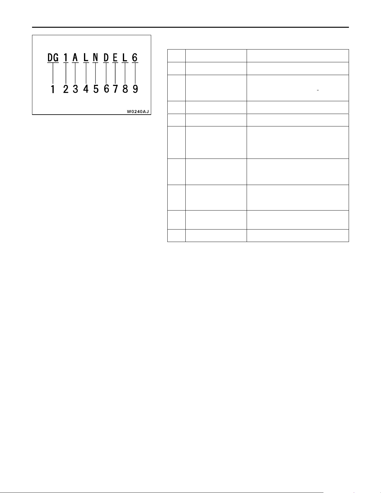
MODEL CODE
No. Items Contents
1 Development DG: MITSUBISHI SPACE STAR
2 Engine type 1: 1,299 mL petrol engine
3 Sort A: Passenger car
4 Body style L: 5-door
5 Transmission type N: 5-speed manual
6 Trim level D: Famil
00-3
4: 1,870 mL diesel engine
5: 1,834 mL petrol engine
transmission
R: 4-speed automatic
transmission
J: Comfort
P: Sport
7 Specification engine
feature
8 Steering wheel
location
9 Destination 6: For Europe
E: MPI
F: DI-D
C: GDI
L: Left hand
R: Right hand
Page 4
00-4
Items
g
GENERAL – Major Specifications
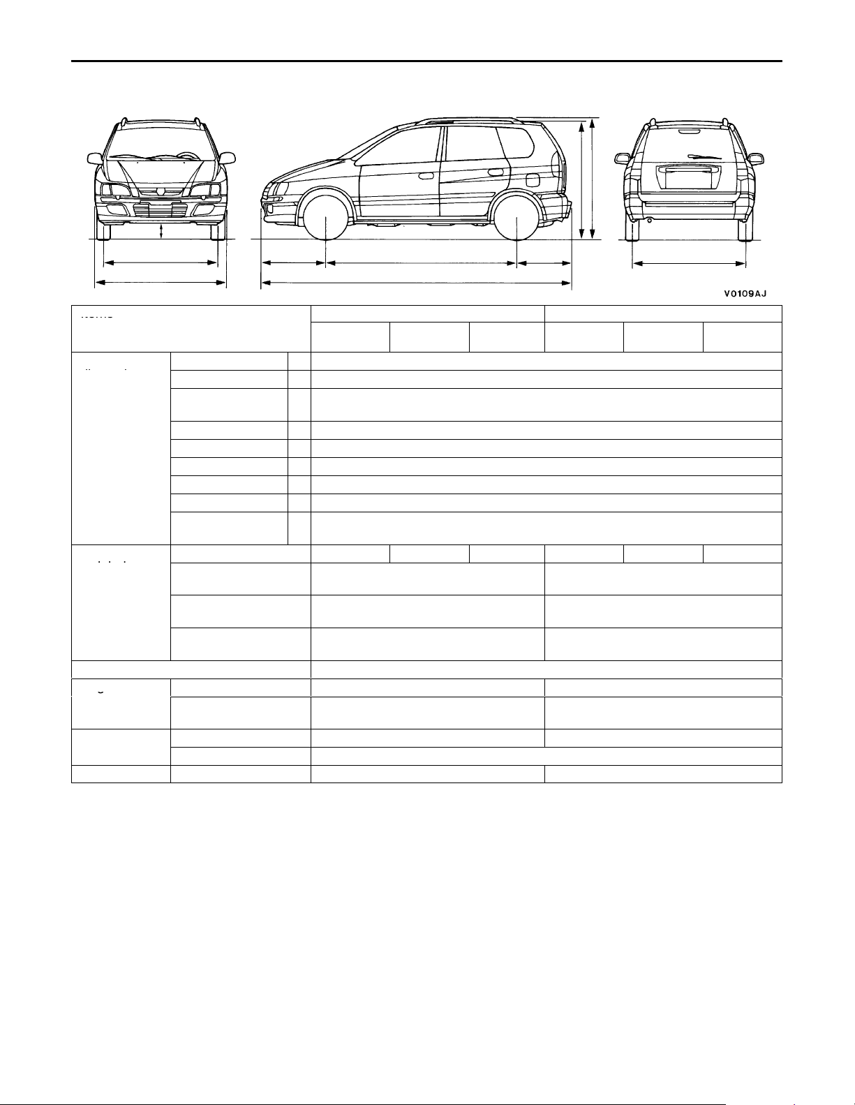
MAJOR SPECIFICATIONS
9
*1
3
3
Items
Vehicle
dimensions
mm
DG1A DG4A
LNDEL6
/R6
Overall length 1 4,030
Overall width 2 1,715
Overall height
(unladen)
3 1,515,
1,555
45
12
LNJEL6
/R6
*1
LNPEL6
/R6
8
LNDFL6
/R6
LNJFL6
/R6
Wheelbase 4 2,500
Track-front 5 1,475
Track-rear 6 1,470
Overhang-front 7 835
Overhang-rear 8 695
Ground clear-
9 155
ance (unladen)
Vehicle
weight kg
Kerb weight 1,158 1,170 1,173 1,248 1,260 1,258
Max. gross vehicle
1,655 1,730
weight
Max. axle weight
855 920
rating-front
Max. axle weight
830 850
rating-rear
Seating capacity 5
Engine
Model No. 4G13 F9Q1
Total displacement
1,299 1,870
mL
Transmission
Model No. F5MR1 F5MV1
Type 5 speed-manual
Fuel system Fuel supply system Multi Point Fuel Injection Direct Injection Diesel
NOTE:
1
*
: Vehicles with roof rails
67
LNPFL6
/R6
Page 5
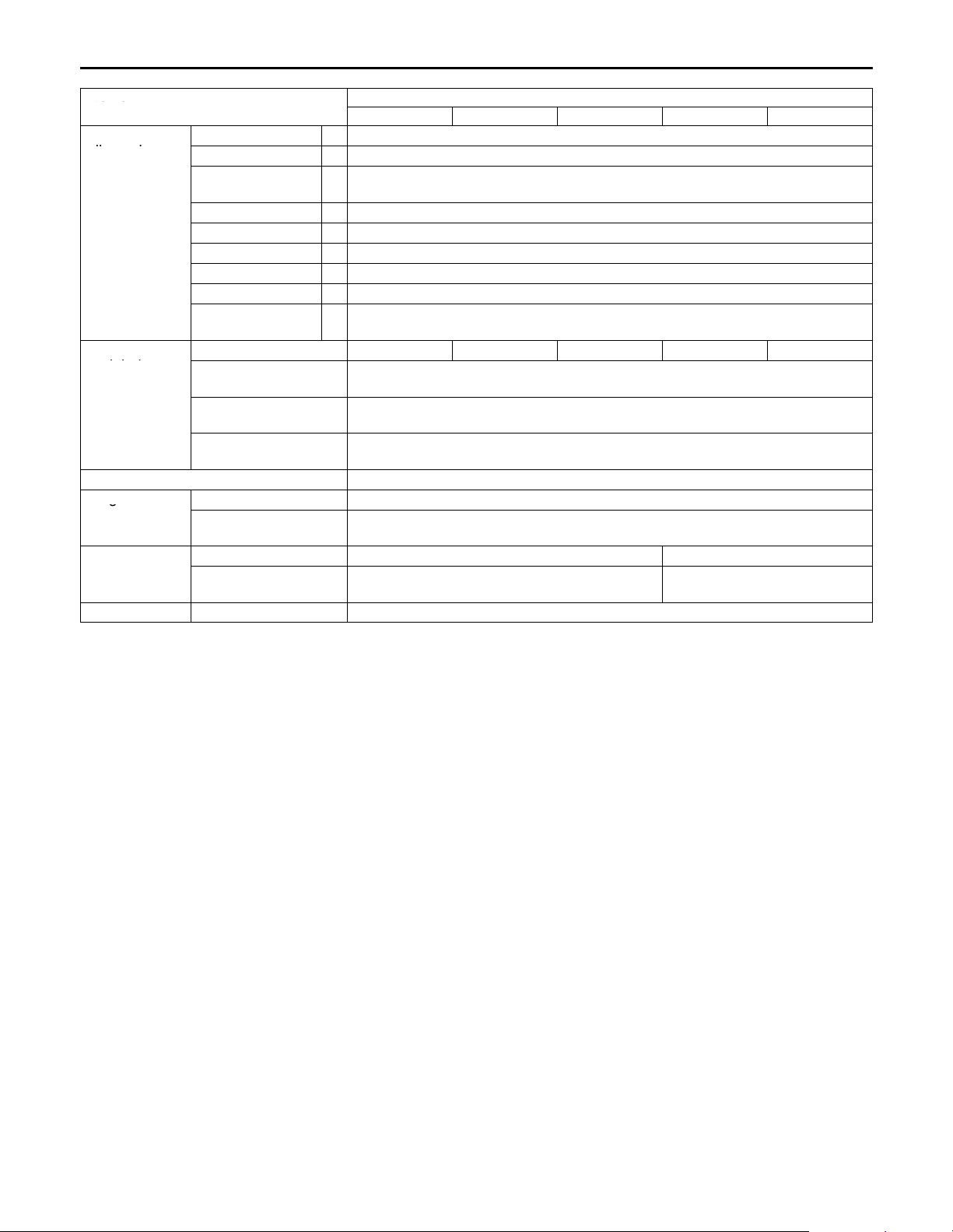
GENERAL – Major Specifications
Items
g
00-5
Items
Vehicle
dimensions
mm
Vehicle
weight kg
Seating capacity 5
Engine
Transmission
Fuel system Fuel supply system Gasoline Direct Injection
NOTE:
1
*
: Vehicles with roof rails
Overall length 1 4,030
Overall width 2 1,715
Overall height
(unladen)
Wheelbase 4 2,500
Track-front 5 1,475
Track-rear 6 1,470
Overhang-front 7 835
Overhang-rear 8 695
Ground clear-
ance (unladen)
Kerb weight 1,228 1,240 1,238 1,255 1,253
Max. gross vehicle
weight
Max. axle weight
rating-front
Max. axle weight
rating-rear
Model No. 4G93
Total displacement
mL
Model No. F5M42 F4A42
Type 5 speed-manual INVECS-II 4A/T with Sports
DG5A
LNDCL6 LNJCL6/R6 LNPCL6/R6 LRJCL6/R6 LRPCL6/R6
3 1,515,
9 150
1,555
1,730
920
850
1,834
*1
Mode
Page 6

NOTES
Page 7

ENGINE
CONTENTS
ENGINE <4G9> 11A. . . . . . . . . . . . . . . . . . . . . . . . . . . . . . . . . . . . . . . . . . . . . . . . . . . . . .
ENGINE <4G1> 11B. . . . . . . . . . . . . . . . . . . . . . . . . . . . . . . . . . . . . . . . . . . . . . . . . . . . . .
ENGINE <F9Q1> 11C. . . . . . . . . . . . . . . . . . . . . . . . . . . . . . . . . . . . . . . . . . . . . . . . . . . . .
11A-1
Page 8

11A-2
ENGINE <4G9>
CONTENTS
GENERAL 3. . . . . . . . . . . . . . . . . . . . . . . . . . . . . . . . .
Outline of Changes 3. . . . . . . . . . . . . . . . . . . . . . . . . . .
SERVICE SPECIFICATIONS 3. . . . . . . . . . . . . . . . .
SEALANTS 3. . . . . . . . . . . . . . . . . . . . . . . . . . . . . . . .
SPECIAL TOOLS 3. . . . . . . . . . . . . . . . . . . . . . . . . . .
CAMSHAFT AND CAMSHAFT OIL SEAL 5. . . .
CRANKSHAFT REAR OIL SEAL <A/T> 10. . . .
CYLINDER HEAD GASKET 12. . . . . . . . . . . . . . . .
ENGINE ASSEMBLY 15. . . . . . . . . . . . . . . . . . . . . .
Page 9
General/Service Specifications/Sealants/Special ToolsENGINE <4G9> –
11A-3
GENERAL
OUTLINE OF CHANGES
Since the resin intake manifold is adopted, the fuel system is changed, and the vehicle with A/T is added
to the lineup, the following service adjustment procedures are made.
Other service procedures are the same as before.
SERVICE SPECIFICATIONS
Items Standard value Limit
Idle speed r/min A/T 650 ± 100 –
Cylinder head bolt shank length mm – 96.4
SEALANTS
Items Specified sealants Remarks
Beam camshaft cap and cylinder
head
Camshaft position sensor support MITSUBISHI GENUINE PART
Drive plate bolt 3M Stud locking 4170 or equivalent –
3M ATD Part No.8660 or equivalent
MD970389 or equivalent
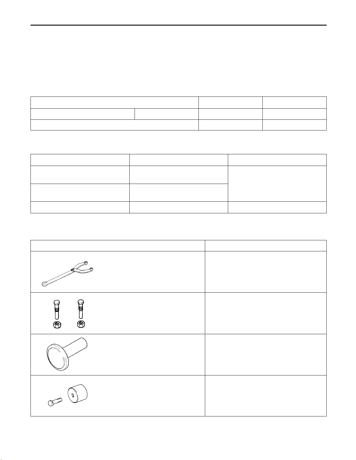
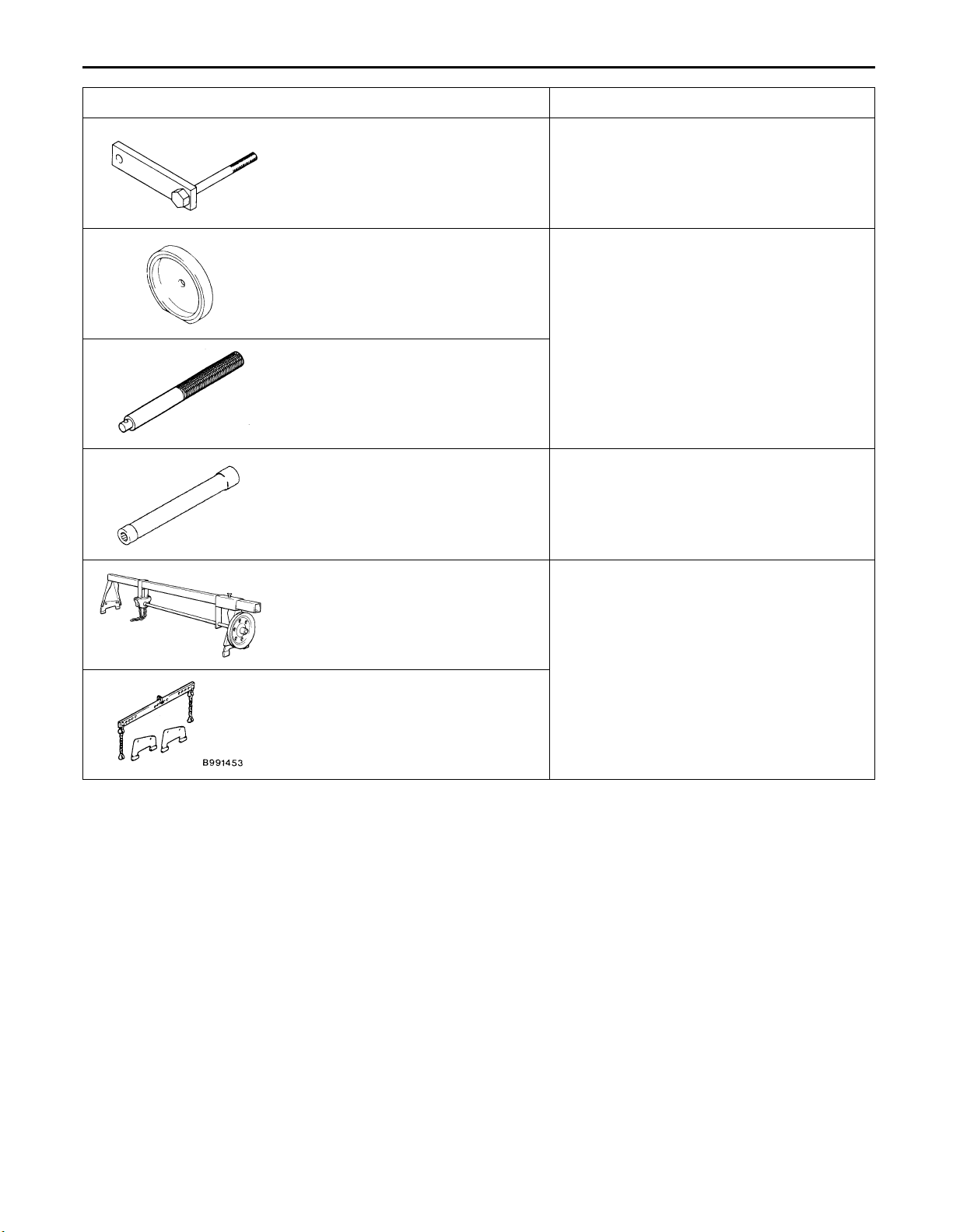
SPECIAL TOOLS
Tool Number Name Use
MB990767 End yoke holder Holding the camshaft sprocket
MD998719 Crankshaft pulley
holder pin
MD998762 Circular packing
installer
Holding the camshaft sprocket
Press-fitting the circular packing
Semi-drying sealant
MD998713 Camshaft oil seal
installer
Press-fitting the camshaft oil seal
Page 10
11A-4
Tool UseNameNumber
MD998781 Flywheel stopper Securing the drive plate
ENGINE <4G9> – Special Tools
MD998776 Crankshaft rear oil
seal installer
MB990938 Handle
MB991653 Cylinder head bolt
wrench
GENERAL
SERVICE
TOOL
MZ203827
MB991453 Engine hanger
Engine lifter Supporting the engine assembly during
assembly
Press-fitting the crankshaft rear oil seal
Cylinder head bolt removal and installation
removal and installation of the transmission
Page 11
ENGINE <4G9> – Camshaft and Camshaft Oil Seal
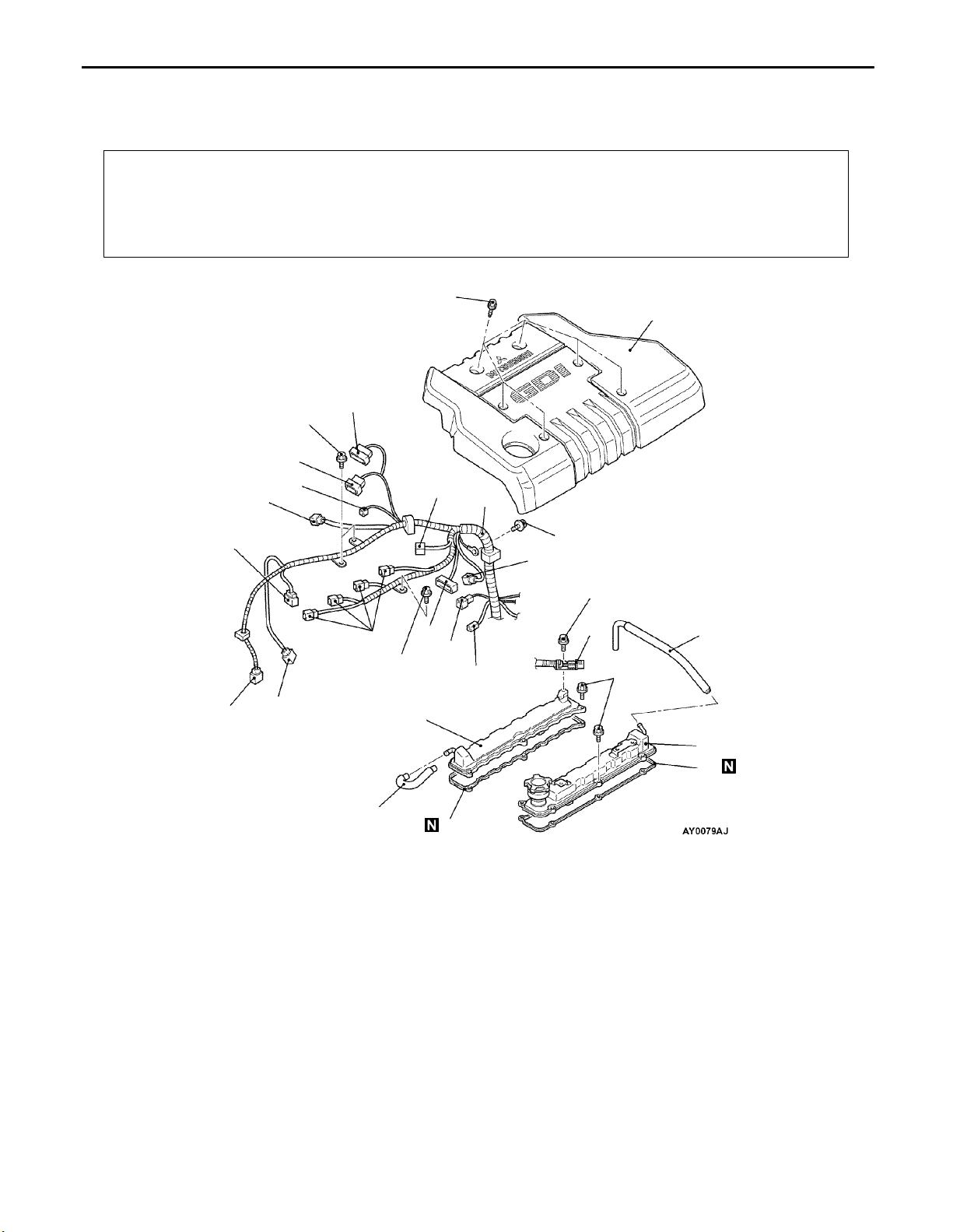
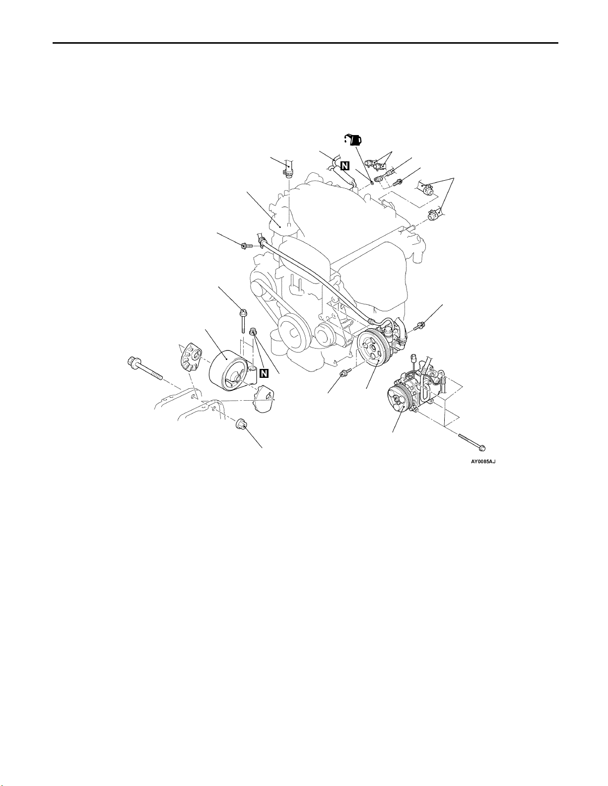
CAMSHAFT AND CAMSHAFT OIL SEAL
REMOVAL AND INSTALLATION
Pre-removal and Post-installation Operation
Prevention of Fuel Discharge <before removal only>
Fuel Leak Check <after installation only>
Air Bleeding the High Pressure Fuel Path
<after installation only>
[Refer to GROUP 13A – Fuel Pump (High pressure).]
3.0 Nm
Under Cover Removal and Installation
Engine Coolant Draining and Supplying
Air Cleaner Removal and Installation
11A-5
1
7.0 Nm
8
7
6
5
3
9
15
5.0 Nm
12
10 – 12 Nm
10
5.0 Nm
11
13
14
2
4
19
18
3.4 Nm
17
21
22
16
20
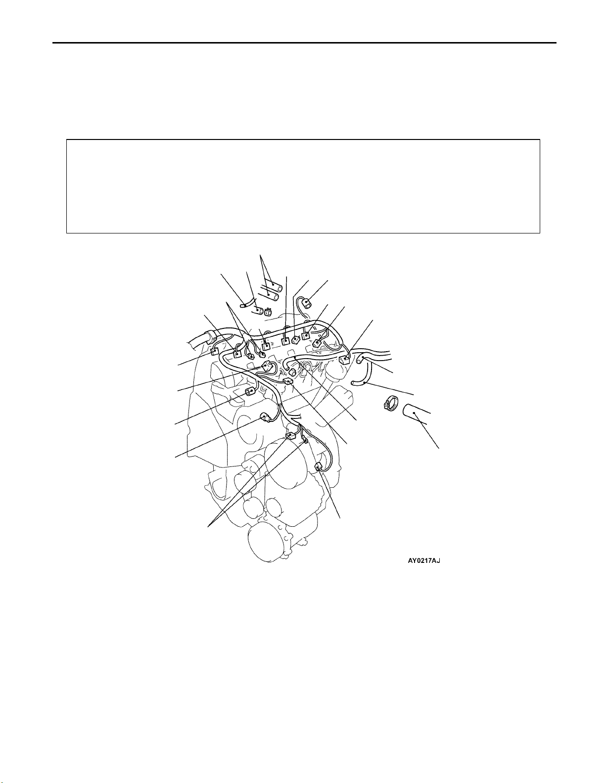
Removal steps
F 1. Engine cover
2. Crank angle sensor connector
3. Fuel pressure sensor
4. Oxygen sensor (front) connector
5. Control wiring harness and EGR
wiring harness combination
connector
6. Purge control solenoid valve
connector
7. Throttle position sensor connector
8. Throttle valve control servo
connector
9. Control wiring harness and injector
wiring harness combination
connector
10. Ignition coil connector
11. Ignition failure sensor connector
12. Camshaft position sensor connector
13. Engine coolant temperature sensor
connector
14. Engine coolant temperature gauge
unit connector
15. Control wiring harness
16. PCV hose
17. Breather hose
Ignition coil (Refer to GROUP 16.
Intake manifold (Refer to GROUP 15.)
Timing belt
18. Connector bracket (injector wiring
harness)
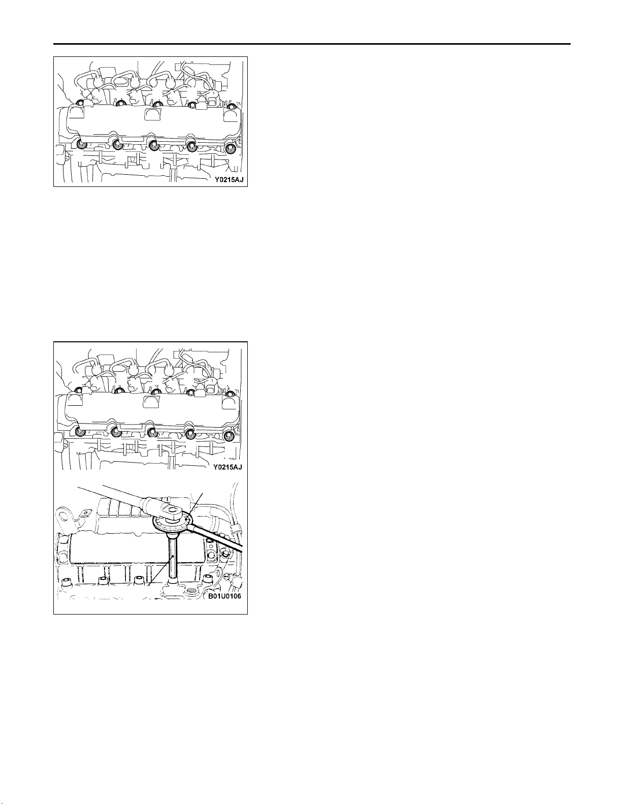
19. Rocker cover (intake side)
20. Rocker cover gasket
21. Rocker cover (exhaust side)
22. Rocker cover gasket
Page 12
11A-6
ENGINE <4G9> – Camshaft and Camshaft Oil Seal
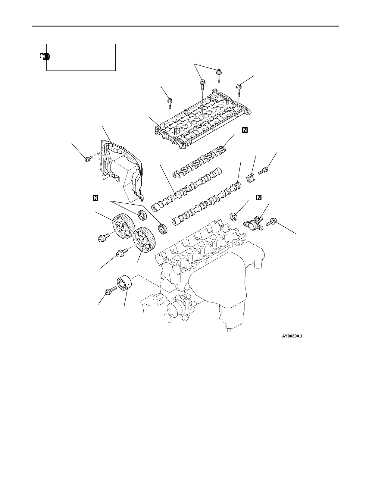
Apply engine oil to all
sliding parts during
installation.
25
10 – 12 Nm
21 – 25 Nm
10 – 12 Nm
29
31
30
32
21 – 25 Nm
33
22 Nm
23
88 Nm
35 Nm
26
24
23
28
27
12 – 15 Nm
AE 23. Camshaft sprocket
24. Idler pulley
25. Timing belt rear upper cover
D 26. Camshaft oil seal
27. Camshaft position sensor support
C 28. Circular packing
Fuel pump (high pressure) assembly
(Refer to GROUP 13A.)
B 29. Beam camshaft cap
30. Beam camshaft cap gasket
A 31. Camshaft (intake side)
A 32. Camshaft (exhaust side)
33. Camshaft position sensing cylinder
Page 13
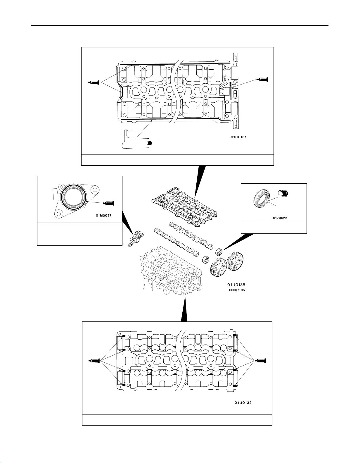
Lubrication points
Sealant: 3M ATD Part No.8660 or equivalent
ENGINE <4G9> – Camshaft and Camshaft Oil Seal
<Seen from underneath
φ3mm
beam camshaft cap>
11A-7
Sealant:
MITSUBISHI GENUINE PART
MD970389 or equivalent
Lip section
Engine oil
<Seen from above cylinder head>
Sealant: 3M ATD Part No.8660 or equivalent
Page 14
11A-8
MB990767
MD998719
ENGINE <4G9> – Camshaft and Camshaft Oil Seal
REMOVAL SERVICE POINT
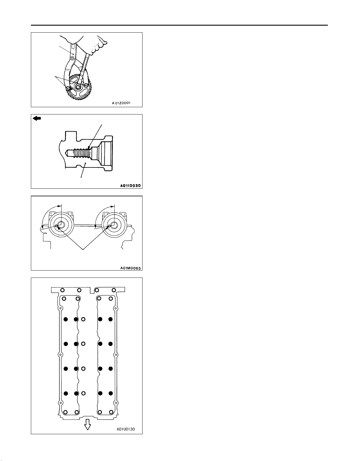
A CAMSHAFT SPROCKET REMOVAL
Camshaft sprocket side
Exhaust camshaft
Approx.
106
Dowel pin
Intake side Exhaust side
28 27 31 32
20 19 23 24
12 11 15 163
Screw hole
Approx.
101
INSTALLATION SERVICE POINTS
A CAMSHAFT INSTALLATION
1. Apply engine oil to journals and cams of the camshafts.
2. Install the camshafts on the cylinder head.
Caution
Be careful not to confuse the intake camshaft with
the exhaust one. There is a screw hole for the cam
position sensing cylinder mounting bolt on the
exhaust-side camshaft.
B BEAM CAMSHAFT CAP INSTALLATION
1. Place the camshaft dowel pin as shown in the illustration.
2. Tighten the beam camshaft cap mounting bolts to the
specified torque in the order shown in the illustration.
Tightening torque:
: 10 – 12 Nm
: 21 – 25 Nm
87 561
Intake side Exhaust
14 13 9 102
22 21 17 184
30 29 25 26
Front of engine
side
Page 15
Press-fitting
depth 2 mm
MD998762
ENGINE <4G9> – Camshaft and Camshaft Oil Seal
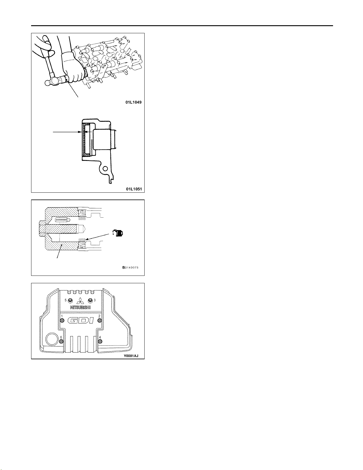
C CIRCULAR PACKING INSTALLATION
Use the special tool to press-fit the circular packing as shown
in the illustration.
11A-9
MD998713
D CAMSHAFT OIL SEAL INSTALLATION
1. Apply engine oil to the entire circumference of the oil seal
lip.
2. Press-fit the oil seal as shown in the illustration.
E CAMSHAFT SPROCKET INSTALLATION
Use the special tool to secure the camshaft sprocket in the
same way as during removal, and then tighten the bolt to
the specified torque.
F ENGINE COVER INSTALLATION
1. Temporarily tighten the mounting bolt in the order of the
numbers shown in the illustration so that the engine cover
can move easily by hand.
2. Tighten the mounting bolt to the specified torque in the
order of the numbers shown in the illustration.
Tightening torque: 3.0 Nm
Page 16
11A-10
ENGINE <4G9> – Crankshaft Rear Oil Seal <A/T>
CRANKSHAFT REAR OIL SEAL <A/T>
REMOVAL AND INSTALLATION
Pre-removal and Post-installation Operation
Transmission Assembly Removal and Installation
(Refer to GROUP 23.)
3
4
1
93 – 103 Nm
2
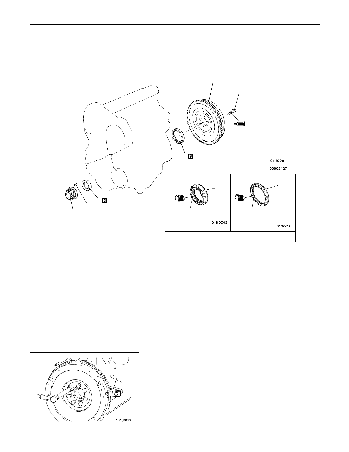
Removal steps
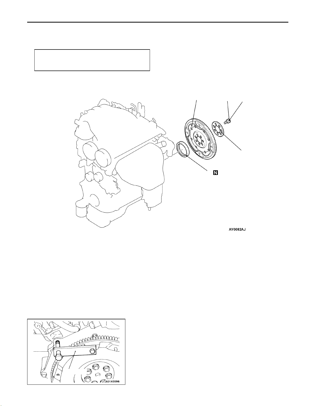
AB 1. Drive plate bolts
B 2. Adapter plate
B 3. Drive plate
A 4. Crankshaft rear oil seal
MD998781
REMOVAL SERVICE POINT
A DRIVE PLATE BOLTS REMOVAL
Use the special tool to secure the drive plate, and remove
the bolts.
Page 17
ENGINE <4G9> – Crankshaft Rear Oil Seal <A/T>
11A-11
Crankshaft
rear oil seal
MD990938
MD998776
Crankshaft
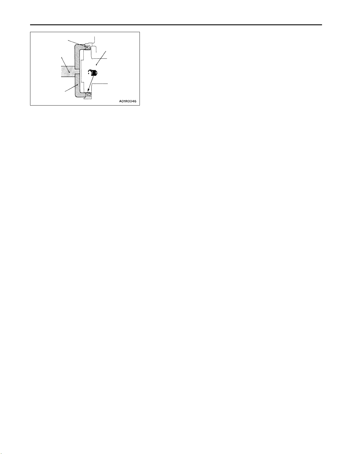
INSTALLATION SERVICE POINTS
A CRANKSHAFT REAR OIL SEAL INSTALLATION
1. Apply a small mount of engine oil to the entire
circumference of the oil seal lip.
2. Install the oil seal by tapping it as far as the chamfered
position of the oil seal case as shown in the illustration.
B DRIVE PLATE/ADAPTOR PLATE/DRIVE PLATE
BOLTS INSTALLATION
1. Clean off all sealant, oil and other substances which are
adhering to the threaded bolts, crankshaft thread holes
and the drive plate.
2. Apply oil to the bearing surface of the drive plate bolts.
3. Apply oil to the crankshaft thread holes.
4. Apply sealant to the threaded mounting holes.
Specified sealant: 3M Stud locking 4170 or equivalent
5. Use the special tool to secure the drive plate, and then
tighten the bolts to the specified torque.
Specified torque: 93 – 103 Nm
Page 18
11A-12
ENGINE <4G9> – Cylinder Head Gasket
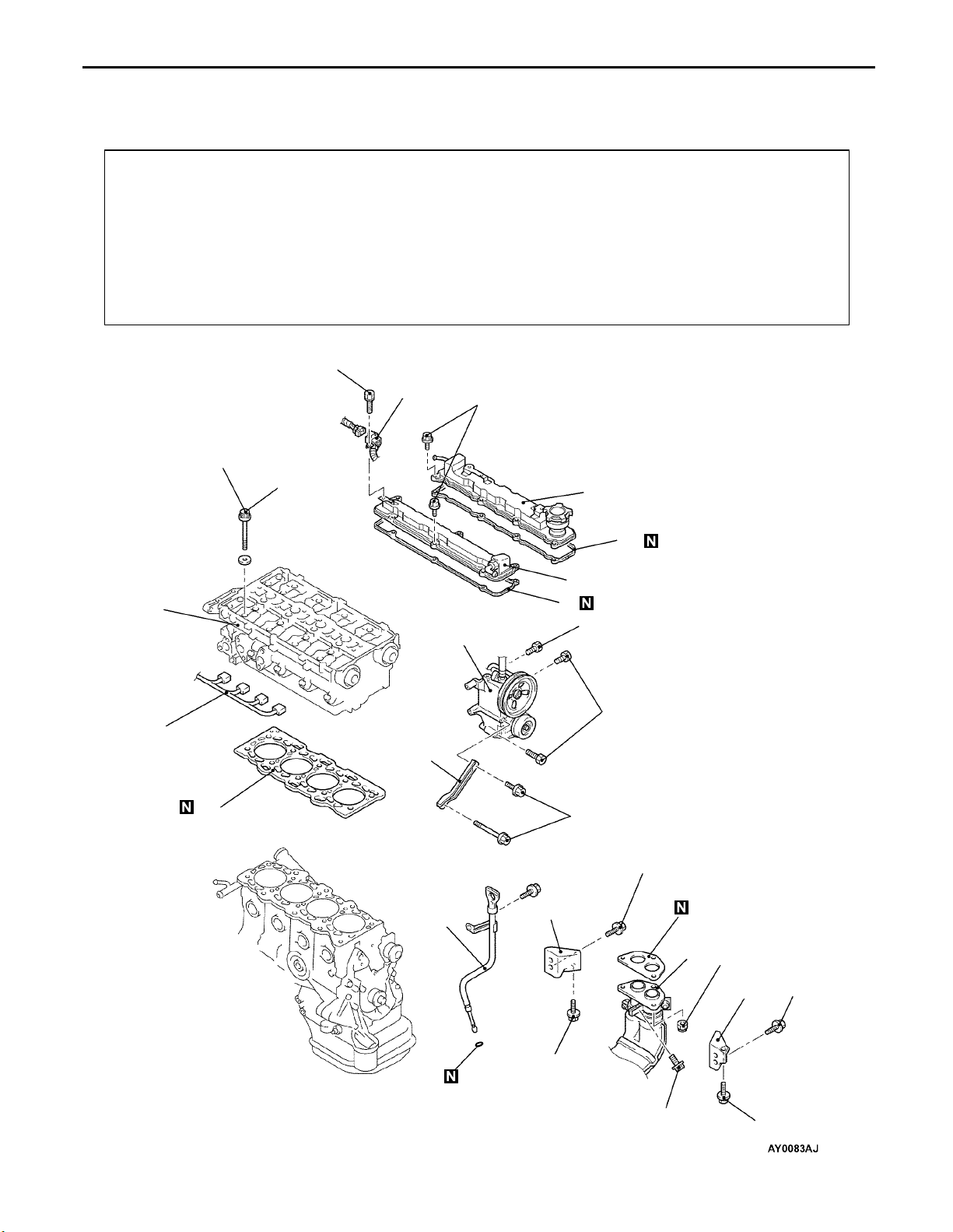
CYLINDER HEAD GASKET
REMOVAL AND INSTALLATION
Pre-removal and Post-installation Operation
Engine Cover Removal and Installation
(Refer to P.11A-5.)
Prevention of Fuel Discharge <before removal only>
Fuel Leak Check <after installation only>
Air Bleeding the High Pressure Fuel Path<after
installation only>
[Refer to GROUP 13A – Fuel Pump (High-pressure).]
Under Cover Removal and Installation
Engine Coolant Draining and Supplying
Engine Oil Draining and Supplying
10 – 12 Nm
74 Nm → 0 Nm → 20 Nm
→ +90 → +90
12
Air Cleaner Removal and Installation
Intake Manifold Removal and Installation
(Refer to GROUP 15.)
Fuel Pump (high-pressure) Assembly Removal and
Installation (Refer to GROUP 13A.)
Timing Belt Rear Upper Cover Removal and
Installation (Refer to P.11A-5.)
Thermostat Case Assembly and Radiator upper hose
Removal and Installation
(Refer to GROUP 14 – Water Hose and Water Pipe.)
7
3.4 Nm
10
13
11
8
9
5
22 Nm
44 Nm
1
4
14
6
3
49 Nm
35 Nm
2
34 Nm
35 Nm
3
19 Nm
34 Nm
19 Nm
Page 19
ENGINE <4G9> – Cylinder Head Gasket
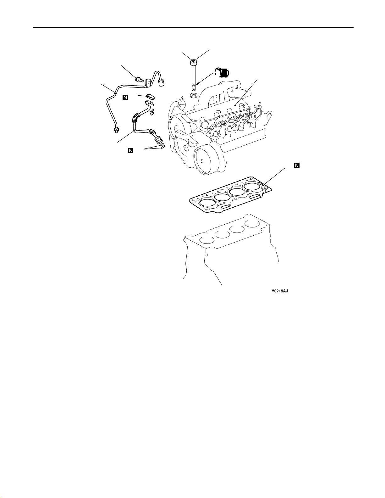
Removal steps
1. Injector harness connector
2. Front exhaust pipe connection
3. Exhaust manifold bracket
4. Power steering oil pump bracket
stay
A 5. Power steering oil pump and brack-
et assembly
6. Engine oil level gauge assembly
7. Connector bracket (injector wiring
harness)
REMOVAL SERVICE POINTS
A POWER STEERING OIL PUMP AND BRACKET
Remove the power steering oil pump and bracket assembly
from the engine with the hose attached.
NOTE
Place the removed power steering oil pump in a place where
it will not be a hindrance when removing and installing the
cylinder head assembly, and tie it with a cord.
11A-13
8. Rocker cover (intake side)
9. Rocker cover gasket
10. Rocker cover (exhaust side)
11. Rocker cover gasket
BB 12. Cylinder head bolt
13. Cylinder head assembly
A 14. Cylinder head gasket
ASSEMBLY REMOVAL
MB991653
Intake side Front of engine
351082
1796 4
Exhaust side
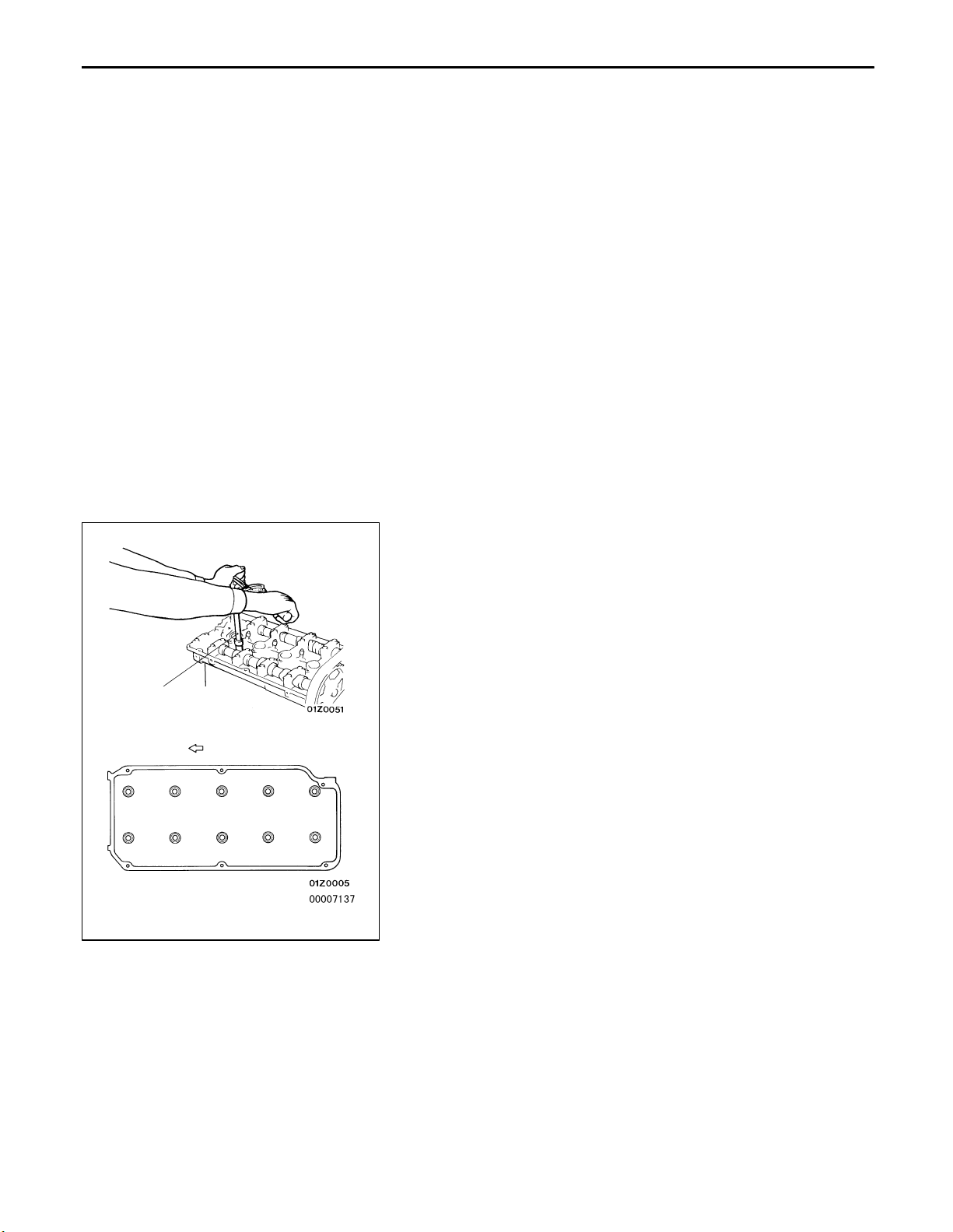
B CYLINDER HEAD BOLT REMOVAL
Use the special tool to loosen the bolts in two or three stages
in the order of the numbers shown in the illustration, and
then remove the bolts.
INSTALLATION SERVICE POINTS
A CYLINDER HEAD GASKET INSTALLATION
1. Wipe off all oil and grease from the gasket mounting
surface.
2. Install so that the shapes of the cylinder head holes match
the shapes of the respective cylinder head gasket holes.
Page 20
11A-14
ENGINE <4G9> – Cylinder Head Gasket
Burred side
Head bolt
A
Intake side Front of engine
washer
Cylinder
head
MB991653
351082
1796 4
Head bolt
(Engine
oil)
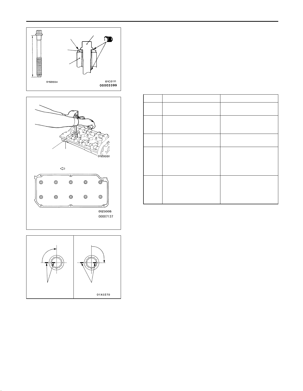
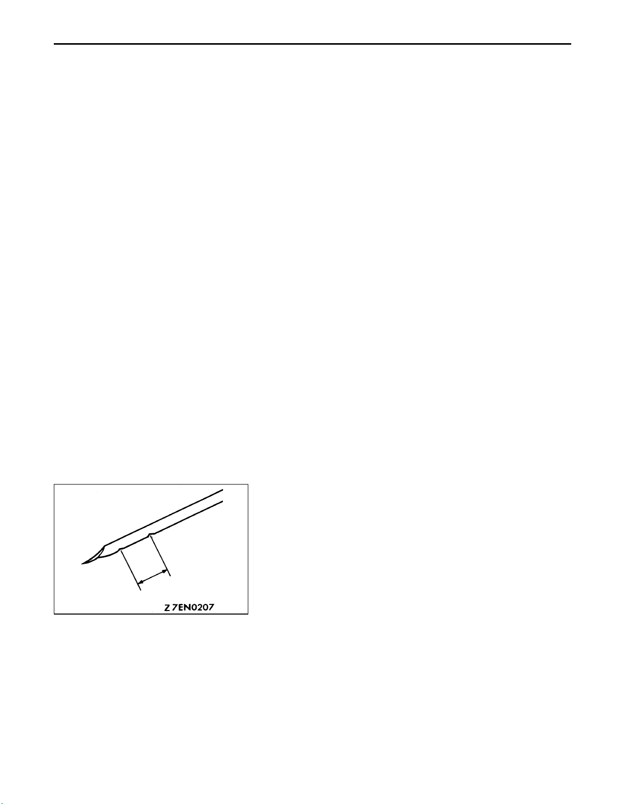
B CYLINDER HEAD BOLT INSTALLATION
1. When installing the cylinder head bolts, the length below
the head of the bolts should be within the limit.
If it is outside the limit, replace the bolts.
Limit (A): 96.4 mm
2. The head bolt washer should be installed with the burred
side caused by tapping out facing upwards.
3. Apply a small amount of engine oil to the thread section
and the washer of the cylinder head bolt.
4. Tighten the bolts by the following procedure.
Step Operation Remarks
1 Tighten to 74 Nm. Carry out in the order
shown in the illustration.
2 Fully loosen. Carry out in the reverse
order of that shown in the
illustration.
3 Tighten to 20 Nm. Carry out in the order
shown in the illustration.
4 Tighten 90 of a turn. In the order shown in the
illustration. Mark the
head of the cylinder head
bolt and cylinder head by
paint.
5 Tighten 90 of a turn. In the order shown in the
illustration. Check that
the painted mark of the
head bolt is lined up with
that of the cylinder head.
Exhaust side
Step 4
90
Painted mark
Caution
(1) Always make a tightening angle just 90. If it is
less than 90, the head bolt will be loosened.
(2) If it is more than 90, remove the head bolt and
repeat the procedure from step 1.
Step 5
90
Painted mark
Page 21
ENGINE <4G9> – Engine Assembly
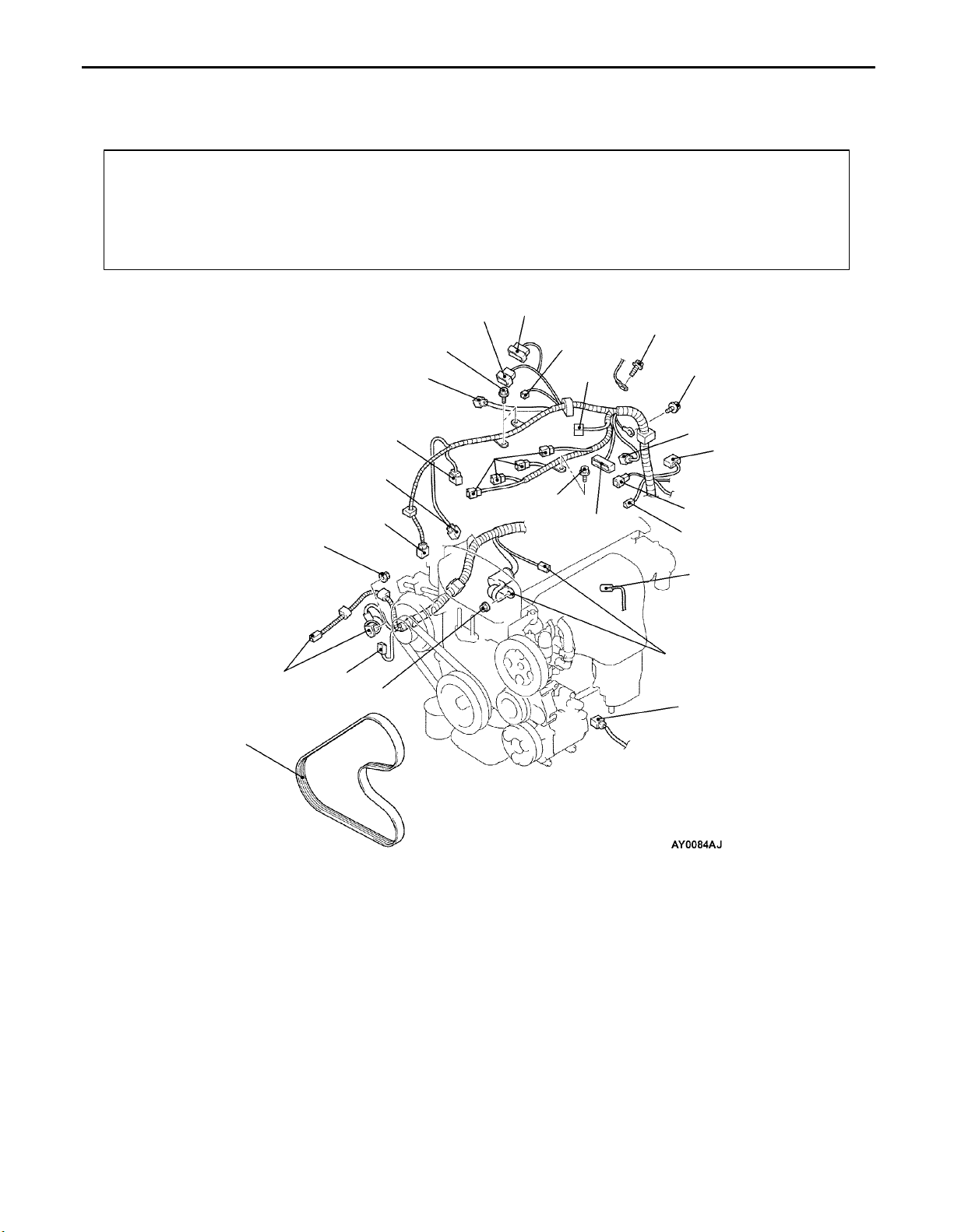
ENGINE ASSEMBLY
REMOVAL AND INSTALLATION
Pre-removal and Post-installation Operation
Engine Cover Removal and Installation
(Refer to P.11A-5.)
Prevention of Fuel Discharge <before removal only>
Air Bleeding the High Pressure Fuel Path
<after installation only>
[Refer to GROUP 13A – Fuel Pump (High pressure).]
11A-15
Fuel Leak Check <after installation only>
Drive Belt Tension Adjustment
Under Cover Removal and Installation
Air Cleaner Removal and Installation
Hood Removal and Installation
Radiator Assembly Removal (Refer to GROUP 14.)
20
9.0 Nm
17
18
2
3
1
9.0 Nm
7.0 Nm
4
6
7
9.0 Nm
5
8
5.0 Nm
11
9
5.0 Nm
10
14
12
13
15
19
16
Removal steps
1. Crank angle sensor connector
2. Fuel pressure sensor
3. Oxygen sensor (front) connector
4. Control wiring harness and EGR
wiring harness combination connector
5. Purge control solenoid valve connector
6. Throttle position sensor connector
7. Throttle valve control servo connector
8. Control wiring harness and injector
wiring harness combination connector
9. Ignition coil connector
10. Ignition failure sensor connector
11. Camshaft position sensor connector
12. Engine coolant temperature sensor
connector
13. Engine coolant temperature gauge
unit connector
14. Detonation sensor connector
15. Power steering oil pressure switch
connector
16. A/C compressor connector
17. Alternator connector
18. Engine oil pressure switch connector
19. Starter connector
20. Drive belt (Power steering and A/C)
Page 22
11A-16
ENGINE <4G9> – Engine Assembly
Caution
Mounting locations marked by * should be provisionally tightened, and then fully tightened when
the body is supporting the full weight of the engine.
(Engine Oil)
12 Nm
67 Nm
29
30
23
57 Nm
24
22 Nm
28
21
26
27
5.0 Nm
25
22 Nm
A 21. Power steering oil pump
B 22. A/C compressor
23. Brake booster vacuum hose
connection
24. Vacuum hose connection
25. Heater hoses connection
D 26. Fuel return hoses connection
C 27. High-pressure fuel hose connection
22
98 – 118 Nm*
C 28. O-ring
Transmission assembly
(Refer to ’99 SPACE STAR Workshop
Manual.)
(Refer to GROUP 23. <A/T>)
CB 29. Engine mount Bracket
DA 30. Engine assembly
Page 23
ENGINE <4G9> – Engine Assembly
REMOVAL SERVICE POINTS
A POWER STEERING OIL PUMP REMOVAL
Remove the power steering oil pump from the engine with
the hose attached.
NOTE
Place the removed power steering oil pump where it will not
be a hindrance when removing and installing the engine
assembly, and tie it with a cord.
B A/C COMPRESSOR REMOVAL
Disconnect the A/C compressor connector and remove the
compressor from the compressor bracket with the hose still
attached.
NOTE
Place the removed A/C compressor where it will not be a
hindrance when removing and installing the engine assembly,
and tie it with a cord.
11A-17
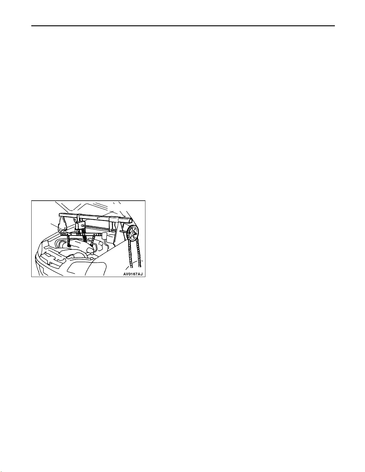
MB991453
MZ203827
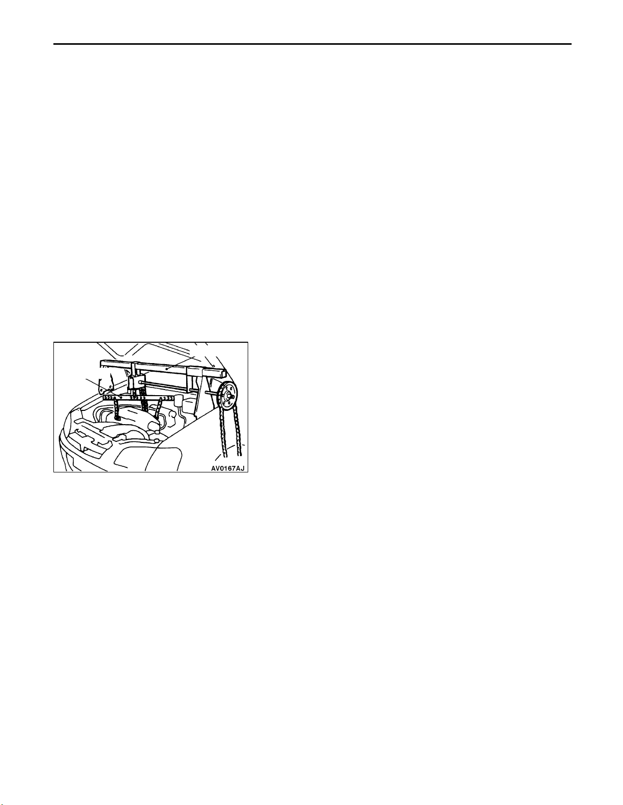
C ENGINE MOUNT BRACKET REMOVAL
1. Support the engine with a garage jack.
2. Remove the mechanical hanger (recommended tool) which
was attached when the transmission assembly was
removed.
3. Hold the engine assembly with a chain block or similar
tool.
4. Place a garage jack against the engine oil pan with a
piece of wood in between, jack up the engine so that
the weight of the engine is no longer being applied to
the engine mount bracket, and then remove the engine
mount bracket.
D ENGINE ASSEMBLY REMOVAL
After checking that all cables, hoses and harness connectors,
etc., are disconnected from the engine, lift the chain block
slowly to remove the engine assembly upward from the engine
compartment.
INSTALLATION SERVICE POINTS
A ENGINE ASSEMBLY INSTALLATION
Install the engine assembly, checking that the cables, hoses,
and harness connectors are not clamped.
Page 24
11A-18
ENGINE <4G9> – Engine Assembly
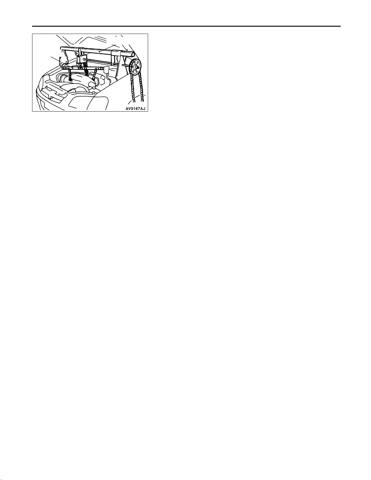
MB991453
MZ203827
B ENGINE MOUNT BRACKET INSTALLATION
1. Place a garage jack against the engine oil pan with a
piece of wood in between, and install the engine mount
bracket while adjusting the position of the engine.
2. Support the engine with the garage jack.
3. Remove the chain block and support the engine assembly
with the mechanical hanger (recommended tool).
C O-RING/HIGH-PRESSURE FUEL HOSE
INSTALLATION
1. Apply a small amount of new engine oil to the O-ring.
Caution
Do not let any engine oil get into the delivery pipe.
2. While turning the high-pressure fuel hose to the right and
left, install the delivery pipe, while being careful not to
damage the O-ring. After installing, check that the hose
turns smoothly.
3. If the hose does not turn smoothly, the O-ring is probably
being clamped. Disconnect the high-pressure fuel hose
and check the O-ring for damage. After this, re-insert the
delivery pipe and check that the hose turns smoothly.
4. Tighten to the specified torque.
Specified torque: 5.0 Nm
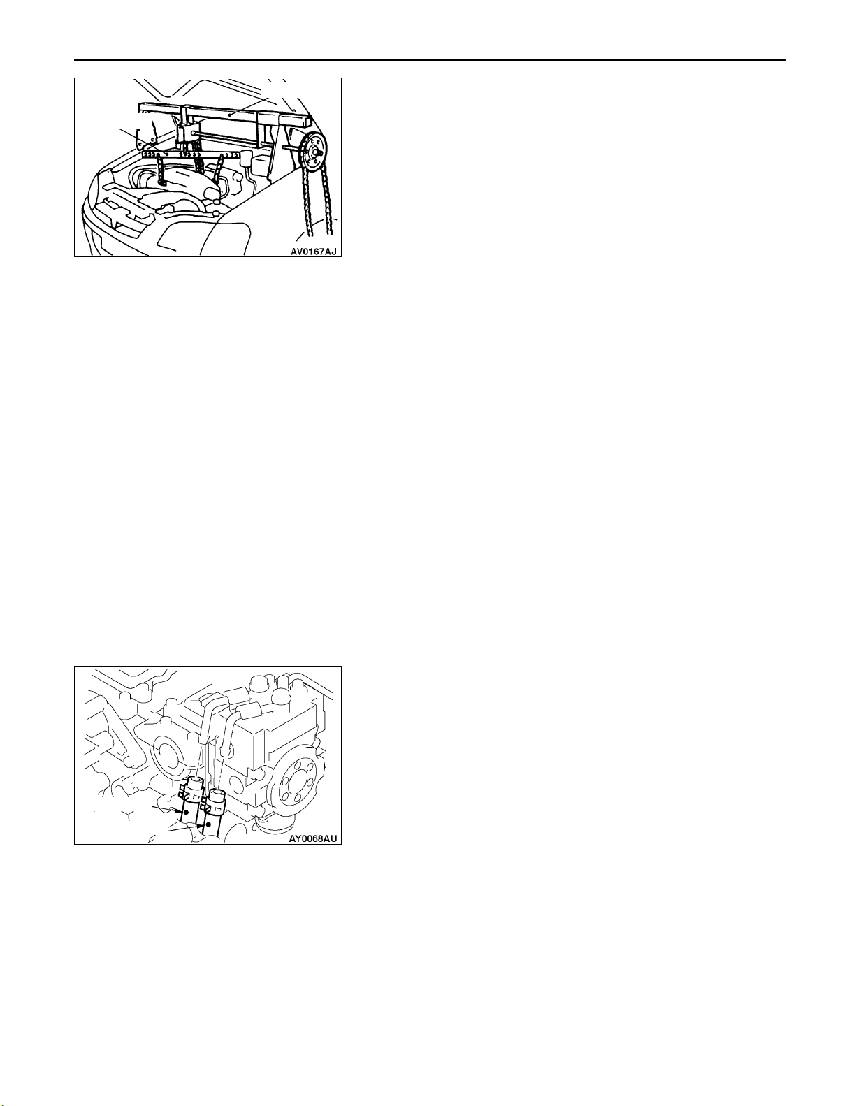
White mark
Blue mark
D FUEL RETURN HOSES INSTALLATION
Install so that the identification marks of the fuel return hoses
are at the positions shown in the illustration.
Page 25

ENGINE <4G1>
CONTENTS
11B-1
GENERAL 2. . . . . . . . . . . . . . . . . . . . . . . . . . . . . . . . .
Outline of Change 2. . . . . . . . . . . . . . . . . . . . . . . . . . . .
GENERAL INFORMATION 2. . . . . . . . . . . . . . . . . .
SERVICE SPECIFICATIONS 2. . . . . . . . . . . . . . . . .
SEALANT 2. . . . . . . . . . . . . . . . . . . . . . . . . . . . . . . . . .
SPECIAL TOOLS 3. . . . . . . . . . . . . . . . . . . . . . . . . . .
ON-VEHICLE SERVICE 4. . . . . . . . . . . . . . . . . . . . .
Ignition Timing Check and Adjustment 4. . . . . . . . . .
Lash Adjuster Check 5. . . . . . . . . . . . . . . . . . . . . . . . . .
CAMSHAFT AND CAMSHAFT OIL SEAL 8. . . .
CRANKSHAFT FRONT OIL SEAL 10. . . . . . . . . .
CYLINDER HEAD GASKET 12. . . . . . . . . . . . . . . .
ENGINE ASSEMBLY 15. . . . . . . . . . . . . . . . . . . . . .
Page 26

11B-2
ENGINE <4G1> –
General/General Information/Service
Specifications/Sealant
GENERAL
OUTLINE OF CHANGE
Since the catalytic converter internal-type exhaust manifold and the auto-lash adjuster are adopted, and
intake manifold and the ignition system are changed, the following service adjustment procedures are
made. Otherwise, the procedures are the same as that of the existing models.
GENERAL INFORMATION
Items 4G13
Auto-lash adjuster Equipped
SERVICE SPECIFICATIONS
Items Standard value Limit
Basic ignition timing 5 BTDC ± 3 –
Cylinder head bolt shank length mm – 103.2
SEALANT
Items Specified sealant Remarks
Camshaft position sensor support MITSUBISHI GENUINE PART
MD970389 or equivalent
Semi-drying sealant
Page 27
ENGINE <4G1> – Special Tools
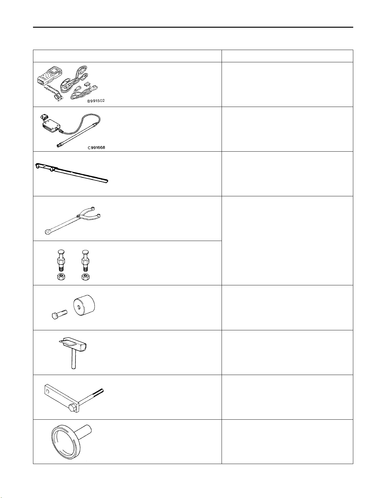
SPECIAL TOOLS
Tool Number Name Use
11B-3
MB991502 MUT-II sub
assembly
MB991668 Belt tension meter
set
MD998747 Crankshaft pulley
holder
MB990767 End yoke holder Holding the camshaft sprocket
MD998719 or
MD998754
Crankshaft pulley
holder pin
Measuring the drive belt tension
Checking the idle speed
Measuring the drive belt tension
(used together with MUT-II)
Holding the crankshaft pulley
MD998713 Camshaft oil seal
installer
MD998727 Oil pan remover Removing the oil pan
MD998781 Fly wheel stopper Securing the flywheel
MD998718 Crankshaft rear oil
seal installer
Press-in of the camshaft oil seal
Press-fitting the crankshaft rear oil seal
Page 28
11B-4
Tool UseNameNumber
ENGINE <4G1> – Special Tools/On-vehicle Service
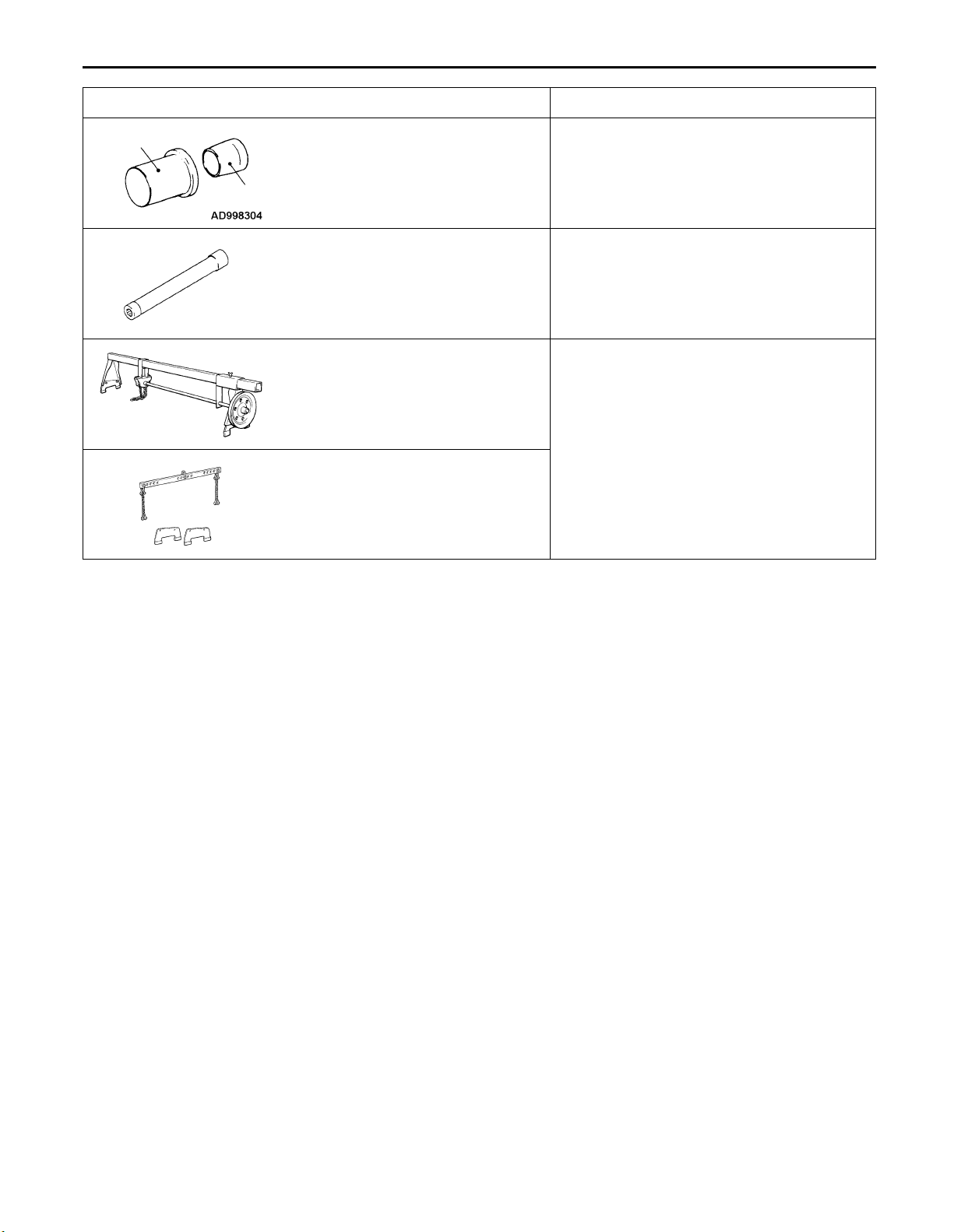
A
A: MD998304
B: MD998305
B
MB991653 Cylinder head bolt
GENERAL
SERVICE
TOOL
MZ203827
MB991453 Engine hanger as-
A: Crankshaft front
oil seal installer
B: Crankshaft front
oil seal guide
wrench
Engine lifter Supporting the engine assembly during
sembly
Press-fitting the crankshaft front oil seal
Cylinder head bolt removal and installation
removal and installation of the transmission
ON-VEHICLE SERVICE
IGNITION TIMING CHECK
1. Set the vehicle to the pre-inspection condition.
2. After turning the ignition switch to the LOCK (OFF) position,
connect the MUT-II to the diagnosis connector.
3. Connect a timing light.
4. Start the engine and run it at idle.
5. Select item No. 22 on the MUT-II and take a reading of the
engine speed. Check that the idle speed is at the standard
value.
Standard value: 750 ± 100 r/min
6. Select item No. 17 (actuator test function) on the MUT-II,
and set the ignition timing to the basic ignition timing.
7. Check the basic ignition timing.
Standard value: 5 BTDC ± 3
8. If the basic ignition timing is outside the standard value
range, check the MPI system while referring to GROUP 13B
– Troubleshooting.
9. Press the CLEAR key on the MUT-II to cancel the basic
ignition timing setting mode by the actuator test function.
Caution
If the mode is not cancelled, the basic ignition timing
setting mode will remain active for 27 minutes, and
problems with engine operation may result if the
vehicle is driven during this period.
Page 29

ENGINE <4G1> – On-vehicle Service
10. Check that the ignition timing is at the standard ignition
timing.
Standard value: Approx. 10 BTDC
NOTE
(1) There should be no problems if the ignition timing
varies within a range of about 7.
(2) At high altitudes, advance the ignition timing by about
a further 5 from the standard value.
LASH ADJUSTER CHECK
If an abnormal noise (knocking) that seems to be coming
from the lash adjuster is heard after starting the engine and
does not stop, carry out the following check.
NOTE
(1) The abnormal noise which is caused by a problem
with the lash adjusters is generated after the engine
is started, and will vary according to the engine speed.
However, this noise is not related to the actual engine
load.
Because of this, if the noise does not occur immediately
after the engine is started, if it does not change in
accordance with the engine speed, or if it changes
in accordance with the engine load, the source of
the noise is not the lash adjusters.
(2) If there is a problem with the lash adjusters, the noise
will almost never disappear, even if the engine has
been run at idle to let it warm up.
The only case where the noise might disappear is
if the oil in the engine has not been looked after properly
and oil sludge has caused the lash adjusters to stick.
1. Start the engine.
2. Check that the noise occurs immediately after the engine
is started, and that the noise changes in accordance with
changes in the engine speed.
If the noise does not occur immediately after the engine
is started, or if it does not change in accordance with
the engine speed, the problem is not being caused by
the lash adjusters, so check for some other cause of the
problem. Moreover, if the noise does not change in
accordance with the engine speed, the cause of the
problem is probably not with the engine. (In these cases,
the lash adjusters are normal.)
11B-5
Page 30
11B-6
ENGINE <4G1> – On-vehicle Service
3. While the engine is idling, check that the noise level does
not change when the engine load is varied.
If the noise level changes, the cause of the noise is probably
parts striking because of worn crankshaft bearings or
connecting rod bearings. (In such cases, the lash adjusters
are normal.)
4. After the engine has warmed up, run it at idle and check
if any noise can be heard.
If the noise has become smaller or disappeared, oil sludge
could make the lash adjusters stick. Clean the lash
adjusters. (Refer to the Engine Workshop Manual.) If not
improved, go to step 5.
5. Bleed air from the lash adjusters.
6. If the noise has not disappeared even after the air bleeding,
clean the lash adjusters. (Refer to the Engine Workshop
Manual.)
<LASH ADJUSTER AIR BLEEDING>
NOTE
(1) If the vehicle is parked on a slope for a long period
of time, the amount of oil inside the lash adjuster will
decrease, and air may get into the high pressure
chamber when starting the engine.
(2) After parking the vehicle for long periods, the oil drains
out of the oil passage, and it takes time for the oil
to be supplied to the lash adjuster, so air can get
into the high pressure chamber.
(3) If either of the above situations occur, the abnormal
noise can be eliminated by bleeding the air from inside
the lash adjusters.
Good
1. Check the engine oil and replenish or replace the oil if
necessary.
NOTE
(1) If there is a only small amount of oil, air will be drawn
in through the oil screen and will get into the oil
passage.
(2) If the amount of oil is greater than normal, then the
oil will being mixed by the crankshaft and a large
amount of air may get mixed into the oil.
(3) If the oil is degenerated, air and oil will not separate
easily in oil, and the amount of air mixed into the
oil will increase.
Page 31
ENGINE <4G1> – On-vehicle Service
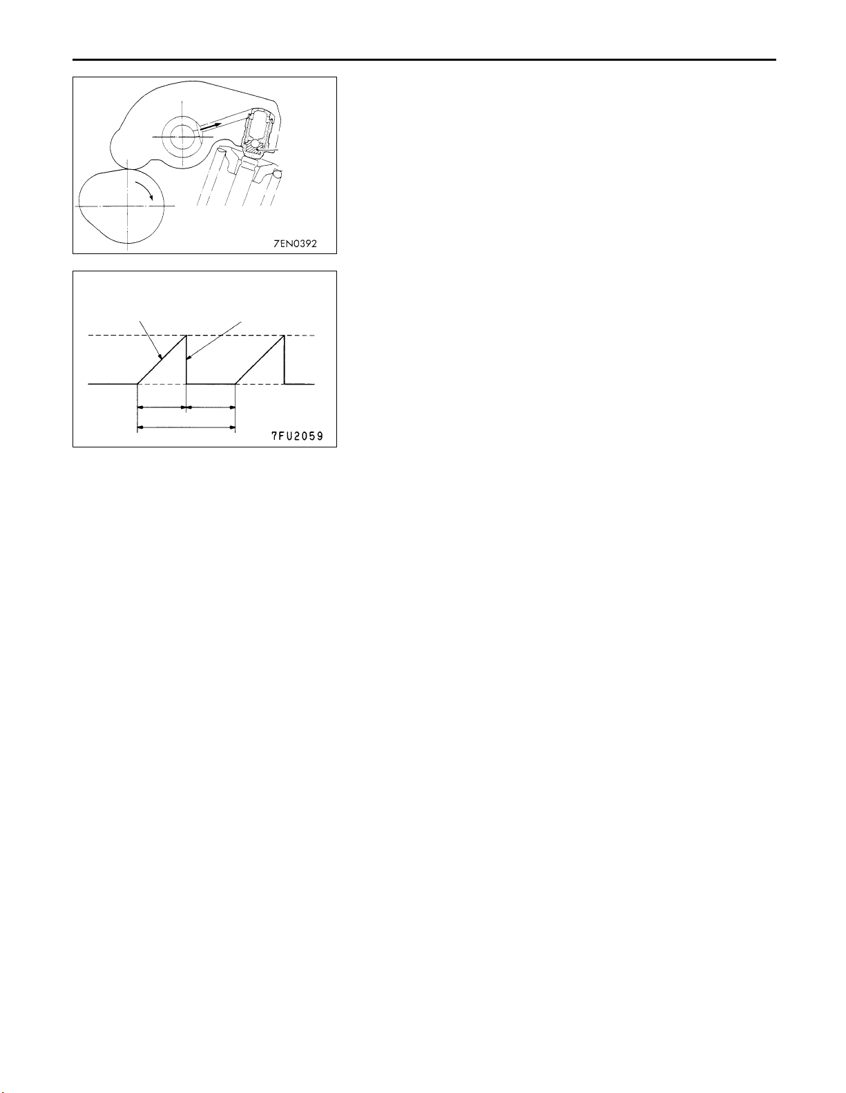
(4) If the air which has been mixed in with the oil due to any
of the above reasons gets into the high pressure
chamber of the lash adjuster, the air inside the high
Highpressure
chamber
pressure chamber will be compressed when the valve
is open and the lash adjuster will over-compress,
resulting in abnormal noise when the valve closes.
This is the same effect as if the valve clearance is
adjusted to be too large by mistake. If the air inside the
lash adjusters is then released, the operation of the
lash adjusters will return to normal.
11B-7
Drive pattern for air bleeding
Gradually open the
throttle valve.
Approx.
3,000 r/min
Idle speed
15
seconds
Once
Close the throttle
valve.
15
seconds
2. Run the engine at idle for 1 – 3 minutes to let it warm
up.
3. With no load on the engine, repeat the drive pattern shown
in the illustration at left and check if the abnormal noise
disappears. (The noise should normally disappear after
10 – 30 repetitions, but if there is no change in the noise
level after 30 repetitions or more, the problem is probably
not due to air inside the lash adjusters.)
4. After the noise has disappeared, repeat the drive pattern
shown in the illustration at left a further 5 times.
5. Run the engine at idle for 1 – 3 minutes and check that
the noise has disappeared.
Page 32

11B-8
ENGINE <4G1> – Camshaft and Camshaft Oil Seal
CAMSHAFT AND CAMSHAFT OIL SEAL
REMOVAL AND INSTALLATION
Pre-removal and Post-installation Operation
Air Cleaner Removal and Installation
Ignition Coil Removal and Installation
(Refer to GROUP16.)
Apply engine oil to all
sliding parts during
installation.
2
4
1
3.5 Nm
9.8 Nm
5.0 Nm
13
12
11
14
3
5
28 – 34 Nm
10
6
16
15
5.0 Nm
12 – 15 Nm
22 Nm
7
9.8 – 12 Nm
9.8 – 12 Nm
8
9
88 Nm
Removal steps
1. Breather hose
2. PCV hose
3. Accelerator cable clamp
4. Rocker cover
5. Rocker cover gasket
6. Spark plug guide
7. Timing belt front upper cover
14
Sealant:
MITSUBISHI GENUINE PART
MD970389 or equivalent
AB 8. Camshaft sprocket
A 9. Camshaft oil seal
10. Rocker arm and shaft assembly
11. Camshaft position sensor connector
12. Ignition failure sensor connector
13. Ignition failure sensor
14. Camshaft position sensor support
15. Camshaft
16. Camshaft position sensing cylinder
Page 33

ENGINE <4G1> – Camshaft and Camshaft Oil Seal
REMOVAL SERVICE POINT
Timing mark
Camshaft
sprocket
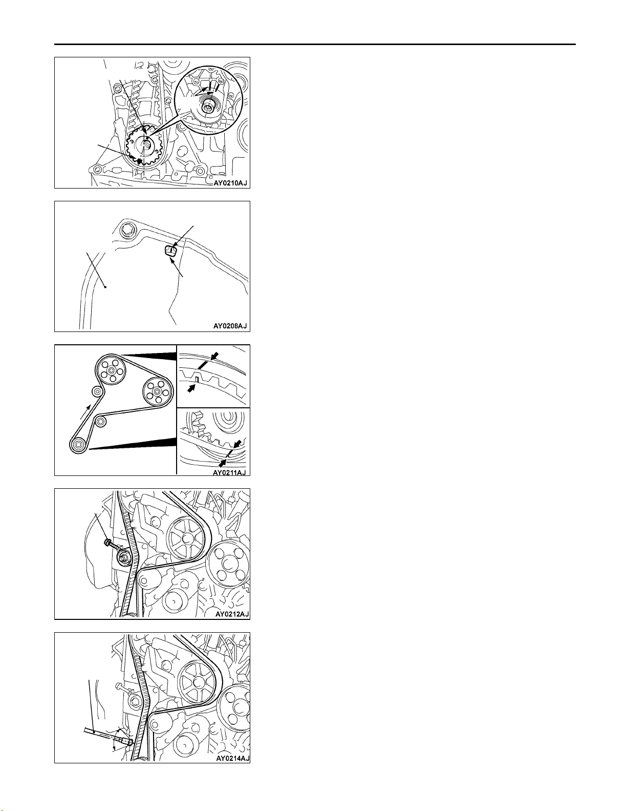
A CAMSHAFT SPROCKET REMOVAL
1. Turn the crankshaft in the forward direction (clockwise)
to align the timing mark so that No.1 cylinder is at the
compression TDC.
Caution
Always turn the crankshaft in the forward direction
(clockwise).
2. Secure the camshaft sprocket and the timing belt with
band cablesto prevent deviation from the relative positions
between the camshaft sprocket and the timing belt.
11B-9
MB990767
MD998719 or
MD998754
MD998713
3. Use the special tool to stop the camshaft sprocket from
turning.
4. Remove the camshaft sprocket with the timing belt
attached.
Caution
Do not turn the crankshaft after the camshaft sprocket
is removed.
INSTALLATION SERVICE POINTS
A CAMSHAFT OIL SEAL INSTALLATION
1. Apply engine oil to the camshaft oil seal lip.
2. Use the special tool to press-fit the camshaft oil seal.
B CAMSHAFT SPROCKET INSTALLATION
Use the special tool to stop the camshaft sprocket from turning
in the same way as was done during removal, and then tighten
the bolts to the specified torque.
Tightening torque: 88 Nm
Page 34

11B-10
ENGINE <4G1> – Crankshaft Front Oil Seal
CRANKSHAFT FRONT OIL SEAL
REMOVAL AND INSTALLATION
5
(Lip)
Engine oil
3
1
Removal steps
Timing belt
Crank angle sensor
(Refer to GROUP 16.)
B 1. Crankshaft sprocket
B 2. Spring pin
B 3. Crankshaft sensing blade
B 4. Crankshaft spacer
A 5. Crankshaft front oil seal
5
4
2
MD998304
MD998305
Crankshaft
Oil seal
INSTALLATION SERVICE POINTS
A CRANKSHAFT FRONT OIL SEAL INSTALLATION
1. Apply a small amount of engine oil to the entire
circumference of the oil seal lip.
2. Tap the oil seal unit it flushes with the oil seal case.
Page 35

ENGINE <4G1> – Crankshaft Front Oil Seal
11B-11
Crankshaft
sprocket
Front of
engine
Spring pin
Crankshaft
sensing blade
Crankshaft
spacer
B CRANKSHAFT SPACER/CRANKSHAFT SENSING
BLADE/SPRING PIN/CRANKSHAFT SPROCKET
INSTALLATION
Install the crankshaft sprocket assembled with the spring pin,
the crankshaft sensing blade, and the crankshaft spacer to
the crankshaft.
Page 36

11B-12
ENGINE <4G1> – Cylinder Head Gasket
CYLINDER HEAD GASKET
REMOVAL AND INSTALLATION
Pre-removal and Post-installation Operation
Prevention of Fuel Discharge <before removal only>
Fuel Leak Check <after installation only>
Under Cover Removal and Installation
Engine Coolant Draining and Supplying
Engine Oil Draining and Supplying
Air Cleaner Removal and Installation
9.8 – 12 Nm
9.8 – 12 Nm
(Engine oil)
19
20
23
21
49 Nm → 0 Nm → 20 Nm → +90 → + 90 (Cold engine)
22
4
8
7
3
2
6
5
6
5
1
16
9
10
11
5.0 Nm
14
12
13
17
17
24 Nm
88 Nm
Removal steps
1. Crank angle sensor connector
2. Detonation sensor connector
3. Boost sensor connector
4. EGR solenoid valve connector
5. Ignition coil connector
6. Injector connector
7. Purge control solenoid valve connector
8. Throttle position sensor connector
9. Idle speed control servo connector
10. Ignition failure sensor connector
11. Camshaft position sensor connector
12. Engine coolant temperature sensor
connector
13. Engine coolant temperature gauge
unit connector
15
35 Nm
14. Oxygen sensor (front) connector
Rocker cover (Refer to P.11B-8.)
Intake manifold
(Refer to GROUP 15.)
Water inlet pipe (Refer to GROUP 14.)
15. Front exhaust pipe connection
16. Front exhaust pipe gasket
17. Oil level gauge assembly
18. O-ring
19. Timing belt front upper cover
AC 20. Camshaft sprocket
BB 21. Cylinder head bolts
22. Cylinder head assembly
A 23. Cylinder head gasket
18
(Engine oil)
Page 37

ENGINE <4G1> – Cylinder Head Gasket
REMOVAL SERVICE POINT
Timing mark
Camshaft
sprocket
A CAMSHAFT SPROCKET REMOVAL
1. Turn the crankshaft in the forward direction (clockwise)
to align the timing mark so that No.1 cylinder is at the
compression TDC.
Caution
Always turn the crankshaft in the forward direction
(clockwise).
2. Secure the camshaft sprocket and the timing belt with
band cablesto prevent deviation from the relative positions
between the camshaft sprocket and the timing belt.
11B-13
MB990767
MD998719 or
MD998754
Intake side
MB991653
Front of engine
3. Use the special tool to stop the camshaft sprocket from
turning.
4. Remove the camshaft sprocket with the timing belt
attached.
Caution
Do not turn the crankshaft after the camshaft sprocket
is removed.
B CYLINDER HEAD BOLT REMOVAL
Use the special tool to loosen the bolts in 2 or 3 steps in
order of the numbers shown in the illustration, and remove
the cylinder head assembly.
Caution
Because the plug guides cannot be replaced by
themselves, be careful not to damage or deform the plug
guides when removing the cylinder head bolts.
3510
1
Exhaust side
7
8
964
2
Page 38

11B-14
ENGINE <4G1> – Cylinder Head Gasket
INSTALLATION SERVICE POINTS
A CYLINDER HEAD GASKET INSTALLATION
1. Wipe off all oil and grease from the gasket mounting
surface.
2. Install so that the shapes of the cylinder head holes match
the shapes of the respective cylinder head gasket holes.
Burred side
Head bolt
A
MB991653
Intake side
washer
Cylinder
head
Front of engine
8613
4
10
257
Head bolt
(Engine
oil)
9
B CYLINDER HEAD BOLT INSTALLATION
1. When installing the cylinder head bolts, the length below
the head of the bolts should be within the limit.
If it is outside the limit, replace the bolts.
Limit (A): 103.2 mm
2. The head bolt washer should be installed with the burred
side caused by tapping out facing upwards.
3. Apply a small amount of engine oil to the thread section
and the washer of the cylinder head bolt.
4. Use the special tool to tighten the bolts by the following
procedure.
Step Operation Remarks
1 Tighten to 49 Nm Carry out in the order
shown in the illustration.
2 Fully loosen. Carry out in the reverse
order of that shown in the
illustration.
3 Tighten to 20 Nm Carry out in the order
shown in the illustration.
4 Tighten 90 of a turn. In the order shown in the
illustration. Mark the head
of the cylinder head bolt
and cylinder head by paint.
5 Tighten 90 of a turn. In the order shown in the
illustration. Check that the
painted mark of the head
bolt is lined up with that of
the cylinder head.
Exhaust side
Step 4
90
Painted mark
Step 5
Painted mark
90
Caution
1. Always make a tightening angle just 90. If it is less
than 90, the head bolt will be loosened.
2. If it is more than 90, remove the head bolt and repeat
the procedure from step 1.
C CAMSHAFT SPROCKET INSTALLATION
Use the special tool to stop the camshaft sprocket from turning
in the same way as was done during removal, and then tighten
the bolts to the specified torque.
Tightening torque: 88 Nm
Page 39
ENGINE <4G1> – Engine Assembly
ENGINE ASSEMBLY
REMOVAL AND INSTALLATION
Pre-removal and Post-installation Operation
Prevention of Fuel Discharge <before removal only>
Fuel Leak Check <after installation only>
Accelerator Cable Adjustment
(Refer to GROUP 17 – On-vehicle Service.)
Drive Belt Tension Adjustment
21
20
19
Under Cover Removal and Installation
Air Cleaner Removal and Installation
Hood Removal and Installation
Radiator Assembly Removal (Refer to GROUP 14.)
8
4
2
7
3
9
12
5
11B-15
11
5.0 Nm
9.0 Nm
9.0 Nm
17
18
22
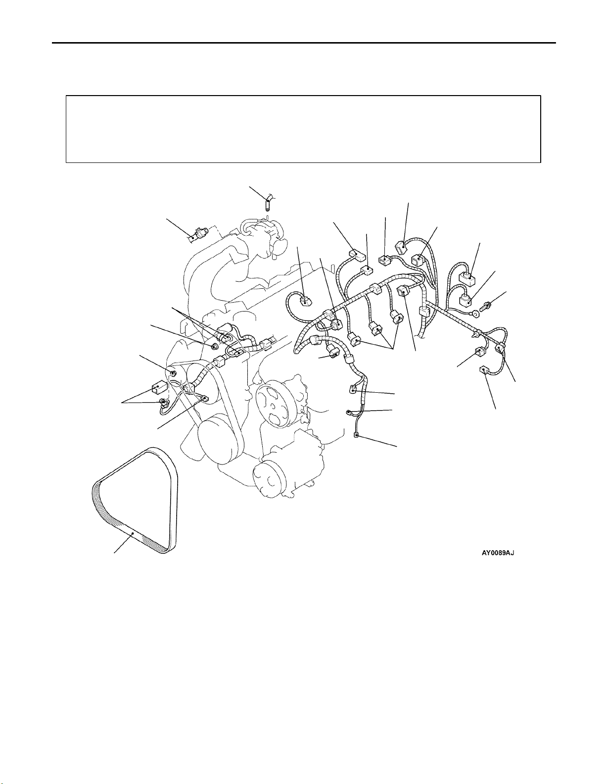
Removal steps
1. Crank angle sensor connector
2. Detonation sensor connector
3. Boost sensor connector
4. EGR solenoid valve connector
5. Ignition coil connector
6. Injector connector
7. Purge control solenoid valve connector
8. Throttle position sensor connector
9. Idle speed control servo connector
10. Ignition failure sensor connector
11. Camshaft position sensor connector
12. Engine coolant temperature sensor
connector
6
6
5
12
1
15
14
13
16
13. Engine coolant temperature gauge
unit connector
14. Oxygen sensor (front) connector
15. Power steering oil pressure switch
connector
16. A/C compressor connector
17. Alternator connector
18. Oil pressure switch connector
19. Starter connector
20. Brake booster vacuum hose connection
21. Vacuum hose connection
22. Drive belt (Power steering and A/C)
Page 40

11B-16
ENGINE <4G1> – Engine Assembly
Caution
*: Indicates parts which should be temporarily tightened, and then fully tightened with the vehicle
on the ground in the unladen condition.
25
30
26
12 Nm
27
5.0 Nm
28
(Engine oil)
67 Nm
57 Nm
29
98 – 118 Nm*
A 23. Power steering oil pump and brack-
et assembly
B 24. A/C compressor
25. Heater hoses connection
26. Fuel return hose connection
39 Nm
23
39 Nm
22 Nm
24
C 27. High-pressure fuel hose connection
C 28. O-ring
Transmission assembly
CB 29. Engine mount Bracket
DA 30. Engine assembly
Page 41
ENGINE <4G1> – Engine Assembly
REMOVAL SERVICE POINTS
A POWER STEERING OIL PUMP REMOVAL
Remove the power steering oil pump and bracket with the
hose attached from the engine.
NOTE
Place the removed power steering oil pump where it will not
be a hindrance when removing and installing the engine
assembly, and tie it with a cord.
B A/C COMPRESSOR REMOVAL
Disconnect the A/C compressor connector and remove the
compressor from the compressor bracket with the hose still
attached.
NOTE
Place the removed A/C compressor where it will not be a
hindrance when removing and installing the engine assembly,
and tie it with a cord.
11B-17
MB991453
MZ203827
C ENGINE MOUNT BRACKET REMOVAL
1. Support the engine with a garage jack.
2. Remove the special tool which was attached when the
transmission assembly was removed.
3. Hold the engine assembly with a chain block or similar
tool.
4. Place a garage jack against the engine oil pan with a
piece of wood in between, jack up the engine so that
the weight of the engine is no longer being applied to
the engine mount bracket, and then remove the engine
mount bracket.
D ENGINE ASSEMBLY REMOVAL
After checking that all cables, hoses and harness connectors,
etc., are disconnected from the engine, lift the chain block
slowly to remove the engine assembly upward from the engine
compartment.
INSTALLATION SERVICE POINTS
A ENGINE ASSEMBLY INSTALLATION
Install the engine assembly, checking that the cables, hoses,
and harness connectors are not clamped.
Page 42
11B-18
ENGINE <4G1> – Engine Assembly
MB991453
MZ203827
B ENGINE MOUNT BRACKET INSTALLATION
1. Place a garage jack against the engine oil pan with a
piece of wood in between, and install the engine mount
bracket while adjusting the position of the engine.
2. Support the engine with the garage jack.
3. Remove the chain block and support the engine assembly
with the special tools.
C FUEL HIGH PRESSURE HOSE INSTALLATION
1. Apply a small amount of new engine oil to the O-ring.
Caution
Do not let any engine oil get into the delivery pipe.
2. While turning the fuel high-pressure hose to the right and
left, install the delivery pipe, while being careful not to
damage the O-ring. After installing, check that the hose
turns smoothly.
3. If the hose does not turn smoothly, the O-ring is probably
being clamped. Disconnect the fuel high-pressure hose
and check the O-ring for damage. After this, re-insert the
delivery pipe and check that the hose turns smoothly.
4. Tighten to the specified torque.
Tightening torque: 5.0 Nm
Page 43

ENGINE <F9Q1>
CONTENTS
11C-1
GENERAL 2. . . . . . . . . . . . . . . . . . . . . . . . . . . . . . . . .
Outline of Change 2. . . . . . . . . . . . . . . . . . . . . . . . . . . .
GENERAL INFORMATION 2. . . . . . . . . . . . . . . . . .
SERVICE SPECIFICATIONS 2. . . . . . . . . . . . . . . . .
SEALANTS 3. . . . . . . . . . . . . . . . . . . . . . . . . . . . . . . .
SPECIAL TOOLS 3. . . . . . . . . . . . . . . . . . . . . . . . . . .
ON-VEHICLE SERVICE 5. . . . . . . . . . . . . . . . . . . . .
Valve Clearance Check and Adjustment 5. . . . . . . .
Idle Speed Check 6. . . . . . . . . . . . . . . . . . . . . . . . . . . . .
Compression Pressure Check 6. . . . . . . . . . . . . . . . . .
Timing Belt Tension Adjustment 7. . . . . . . . . . . . . . . .
CRANKSHAFT PULLEY 8. . . . . . . . . . . . . . . . . . . . .
CAMSHAFT AND CAMSHAFT OIL SEAL
10. . . . . . . . . . . . . . . . . . . . . . . . . . . . . . . . . . . . . . . . . . .
OIL PAN 12. . . . . . . . . . . . . . . . . . . . . . . . . . . . . . . . . .
CRANKSHAFT OIL SEAL 13. . . . . . . . . . . . . . . . . .
CYLINDER HEAD GASKET 15. . . . . . . . . . . . . . . .
TIMING BELT 18. . . . . . . . . . . . . . . . . . . . . . . . . . . . .
ENGINE ASSEMBLY 22. . . . . . . . . . . . . . . . . . . . . .
Page 44

11C-2
(at
ld)
ENGINE <F9Q1> – General/General Information/Service Specifications
GENERAL
OUTLINE OF CHANGE
The following maintenance service points have been established to correspond to the adoption of the
F9Q1 engine.
GENERAL INFORMATION
Items Specification
Total displacement mL 1,870
Bore × Stroke mm 80 × 93
Compression ratio 19
Combustion chamber Direct injection type
Camshaft arrangement SOHC
Number of valve
Valve timing Intake
Fuel system Common rail fuel injection
Intake 4
Exhaust 4
Opening 3 BTDC
Closing 21 ABDC
Exhaust
Opening 46 BBDC
Closing 6 BTDC
SERVICE SPECIFICATIONS
Items Standard value Limit
Valve clearance
co
mm checking
Idle speed r/min 750 ± 10 –
When
When
adjusting
Intake valve 0.15 – 0.25 –
Exhaust valve 0.35 – 0.45 –
Intake valve 0.20 –
Exhaust valve 0.40 –
Compression pressure (250 – 400 r/min) kPa – Min. 2,000
Compression pressure difference of all cylinder kPa – Max. 400
Timing belt frequency Hz 90 ± 15 –
Page 45

ENGINE <F9Q1> – Sealants/Special Tools
MD970389
t
SEALANTS
Item Specified sealant Remark
11C-3
Oil pan
Beam cam cap
Fly wheel bolt 3M stud locking 4170 or equivalent Anaerobic sealant
MITSUBISHI GENUINE PART
or equivalen
Semi-drying sealant
SPECIAL TOOLS
Tool Number Name Use
MB991502 MUT-II sub
assembly
MB991668 Belt tension meter
set
MD998747 Crankshaft pulley
holder
Measuring the drive belt tension
Checking the idle speed
Measuring the drive belt tension
(Used together with the MUT-II)
Holding the crankshaft pulley
MB991614 Angle gauge Tightening of the crankshaft pulley bolt
Tightening of the cylinder head bolts
MB990767 End yoke holder Holding the camshaft sprocket
MD998719 Crankshaft pulley
holder pin
MB996042 Oil seal installer Installation of camshaft oil seal
Page 46

11C-4
Tool UseNameNumber
MB996015 Flywheel stopper Locking the flywheel
MB996038 Oil seal installer Installation of the crankshaft rear oil seal
MB996040 Oil seal installer Installation of the crankshaft front oil seal
ENGINE <F9Q1> – Special Tools
GENERAL
SERVICE
TOOL
MZ203827
MB991453 Engine hanger
Engine lifter Supporting the engine assembly during
assembly
removal and installation of the transmission
Page 47

ENGINE <F9Q1> – On-vehicle Service
ON-VEHICLE SERVICE
VALVE CLEARANCE CHECK AND ADJUSTMENT
1. The valve clearances have to be checked/adjusted in the
following sequence.
Cylinder at point of balance Cylinder being checked/
11C-5
adjusted
Cylinder at point
of balance
Cylinder being
checked/adjusted
1 4
2 3
3 2
4 1
2. Measure the valve clearance.
Standard value:
Cold engine Checking Adjusting
Intake valve mm 0.15 – 0.20 0.20
Exhaust valve mm 0.35 – 0.45 0.40
3. If the valve clearance is outside the standard value, adjust
by replacing the tappets using the following procedure.
4. Re-measure the places which were outside the standard
value, and make a note of the measurement value.
Adapter
Thickness
(X)
Micrometer
5. Measure the thickness of the tappet (X) with a micrometer.
6. Select a tappet which will bring the valve clearance to then
standard value based on the measurement value.
Thickness of tappet for adjustment =
Thickness of tappet installed during inspection (X)
+ (measurement value – standard value)
NOTE
(1) Measure the thickness of the tappet pad with a
micrometer.
(2) Always use new tappets.
(3) Tappets are available in thickness from 7.550 mm
to 8.150 mm, increasing by increments of 0.025 mm.
7. Remove the camshaft, and then install the selected tappet.
8. Install the camshaft.
9. After rotating the camshaft once, check that the valve
clearances are at the standard values.
Page 48

11C-6
ENGINE <F9Q1> – On-vehicle Service
IDLE SPEED CHECK
1. Before inspection, set the vehicle to the pre-inspection
condition.
2. Turn the ignition switch to the “LOCK” (OFF) position and
the connect the MUT-II to the diagnosis connector.
3. Start the engine and check that the idle speed is at the
standard value.
Standard value: 750 ± 10 r/min
4. If the idle speed is not at the standard value, refer to
GROUP 13D – Troubleshooting.
COMPRESSION PRESSURE CHECK
1. Before inspection, check that the engine oil, starter and
battery are normal. In addition, set the vehicle to the
pre-inspection condition.
2. Disconnect the all injector connector.
NOTE
Doing this will prevent carrying out fuel injection.
3. Remove all of the glow plugs.
4. Cover the glow plug hole with a shop towel etc., and after
the engine has been cranked, check that no foreign material
is adhering to the shop towel.
Caution
(1) Keep away from the glow plug hole when cranking.
(2) If compression is measured with water, oil, fuel,
etc., that has come from cranks inside the cylinder,
these materials will become heated and will gush
out from glow plug hole, which is dangerous.
5. Set compression gauge to one of the glow plug holes.
6. Crank the engine and measure the compression pressure.
Limit: Min. 2000 kPa
7. Measure the compression pressure for all cylinders, and
check that the pressure differences of the cylinders are
below the limit.
Limit: Max. 400 kPa
8. If there is a cylinder with compression or a compression
difference that is outside the limit, pour a small amount of
engine oil through the glow plug hole, and repeat the
operations in steps 6 and 7.
(1) If the compression increases after oil is added, the
cause of the malfunction is a worn or damaged piston
ring and/or cylinder inner surface.
(2) If the compression does not rise after oil is added,
the cause is a burnt or defective valve seat, or pressure
is leaking from the gasket.
9. Install the glow plugs.
10. Connect the injector connectors.
Page 49

15
15
MB991668
(Microphone)
10 – 20 mm
M6
bolt
ENGINE <F9Q1> – On-vehicle Service
TIMING BELT TENSION ADJUSTMENT
1. Connect the special tool (belt tension meter set) to the
MUT-II.
2. Connect the MUT-II to the diagnosis connector.
3. Remove the timing belt cover.
4. Turn the crankshaft clockwise to set the No. 1 cylinder to top
dead compression centre.
5. Turn the ignition switch to “ON” position and select “Belt
tension measurement” from the MUT-II menu screen.
6. Slacken the lock nut of the timing belt tensioner.
7. Tension the timing belt with the aid of an M6 bolt.
8. As shown in the illustration, keep the microphone
(MB991668) 10 to 20 mm away from the back side of the
belt perpendicularly (within an inclination of ±15 degrees).
9. With your finger tip lightly tap the centre of the belt between
the tensioner and crankshaft sprocket in the location shown
Lock nut
by the arrow in the illustration to check whether the belt
frequency in within the standard value.
Standard value: 90 ± 15 Hz
Caution
(1) Measure when the belt surface temperature is
close to room temperature.
(2) Make sure that the water or oil, etc., does not get
on the microphone.
(3) If a strong wind blows or noise is made close
to the microphone during measure, the meter will
show a value that differs from the actual value.
(4) If the measurement is taken with the microphone
touching the belt, the meter will show a value that
differs from the actual value.
(5) Do not measure while the engine is running.
11C-7
Page 50

11C-8
ENGINE <F9Q1> – Crankshaft Pulley
CRANKSHAFT PULLEY
REMOVAL AND INSTALLATION
Pre-removal and Post-installation Operation
Under Cover Removal and Installation
10 Nm
2
10 Nm
1
1
10 Nm
5
4
25 Nm
20 Nm → + 115 ± 15
3
Removal steps
1. A/C suction hose clump
2. Power steering pressure hose
clamp
A 3. Engine-ECU assembly
B 4. Drive belt
CA 5. Crankshaft pulley
REMOVAL SERVICE POINTS
A ENGINE-ECU ASSEMBLY REMOVAL
Remove the engine
to hold in the location where the removal of drive belt cannot
be hindered.
-ECU assembly with the harness attached
Page 51

ENGINE <F9Q1> – Crankshaft Pulley
11C-9
Belt’s automatic
pulley tensioner
MD998747
MB991614
Drive belt
Drive belt
B DRIVE BELT REMOVAL
1. Loosen the belt’s automatic pulley tensioner mounting bolt.
2. Hook 16 mm wrench to the protrusion of the belt’s automatic
pulley tensioner and turn the belt’s automatic pulley
tensioner clockwise to remove the drive belt.
Caution
Do not use the removed drive belt again. Always make
sure to replace the used drive belt with a new one.
C CRANKSHAFT PULLEY REMOVAL
Caution
1. This drive belt will get damaged. Do not use the
engine’s drive belt.
2. Never use a damaged drive belt.
INSTALLATION SERVICE POINT
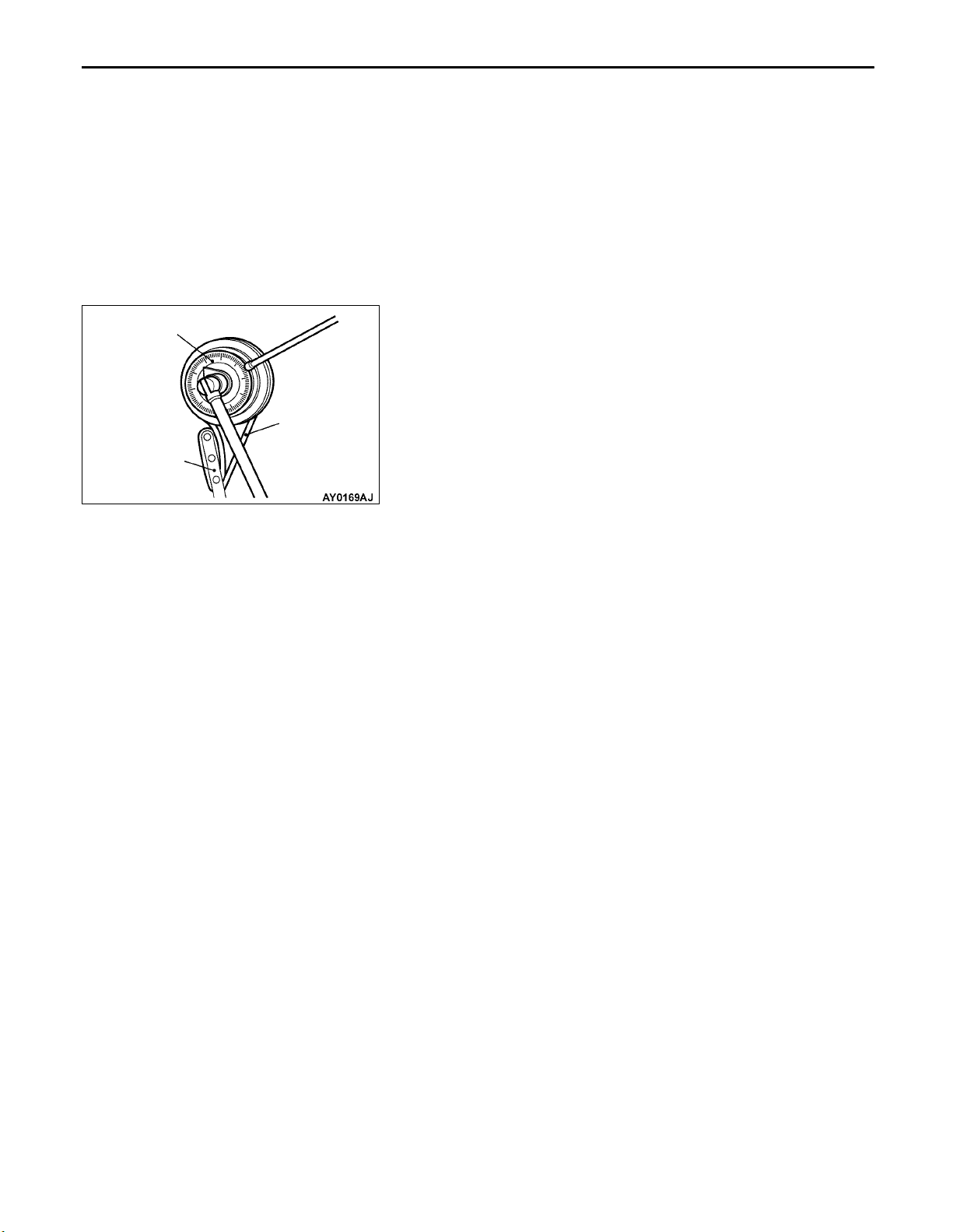
A CRANKSHAFT PULLEY INSTALLATION
1. Use the special tool to hold the crankshaft pulley.
2. Tighten the crankshaft pulley mounting bolt to 20 Nm.
3. Place the special tool in a wrench to tighten the crankshaft
pulley mounting bolt to 115°±15°.
MD998747
Page 52

11C-10
ENGINE <F9Q1> – Camshaft and Camshaft Oil Seal
CAMSHAFT AND CAMSHAFT OIL SEAL
REMOVAL AND INSTALLATION
Pre-removal and Post-installation Operation
Engine Coolant Draining and Supplying
(Refer to GROUP 14 – On-vehicle Service.)
Air Cleaner Removal and Installation
(Refer to GROUP 15.)
7
Timing Belt Removal and Installation
(Refer to P.11C-18.)
5 Nm
7
Sealant:
MITSUBISHI GENUINE PART
MD970389 or equivalent
1
50 Nm
10 Nm
8
11
4
22 Nm
6
13
12
2
3
5
10
10 Nm
9
3
Lip section
Removal steps
AC 1. Camshaft sprocket
2. Timing belt under cover upper
B 3. Camshaft oil seal
4. Brake booster vacuum hose
connection
5. Vacuum hose connection
6. Vacuum pump assembly
Engine oil
7. Rocker cover
8. Rocker cover gasket
9. Radiator upper hose connection
10. Water inlet fitting
A 11. Beam camshaft cap
12. Camshaft
13. Key
Page 53

MB990767
MD998719
ENGINE <F9Q1> – Camshaft and Camshaft Oil SealENGINE <F9Q1> – Camshaft and Camshaft Oil Seal
REMOVAL SERVICE POINT
A CAMSHAFT SPROCKET REMOVAL
11C-11
Front of the engine
MB996042
INSTALLATION SERVICE POINTS
A BEAM CAMSHAFT CAP INSTALLATION
Tighten the beam camshaft cap mounting bolts to the specified
torque in the order shown in the illustration.
Tightening torque: 10 Nm
B CAMSHAFT OIL SEAL INSTALLATION
1. Coat the lip of the oil seal with a thin layer of engine
oil.
2. Tape off the camshaft.
3. Locate the oil seal over the camshaft.
4. Fit the oil seal with the special tool.
C CAMSHAFT SPROCKET INSTALLATION
Use the special tool to secure the camshaft sprocket in the
same way as during removal, and then tighten the bolt to
the specified torque.
Page 54

11C-12
ENGINE <F9Q1> – Oil Pan
OIL PAN
REMOVAL AND INSTALLATION
Pre-removal and Post-installation Operation
Under Cover Removal and Installation
Engine Oil Draining and Supplying
(Refer to GROUP 12 – On-vehicle Service.)
3
Sealant:
MITSUBISHI GENUINE PART
MD970389 or equivalent
Oil Level Gauge Removal and Installation
Removal steps
1. Drain plug
2. Drain plug gasket
A 3. Oil pan
Oil pan
Flat-tipped
screwdriver
Notch
13 Nm
3
25 Nm
2
1
REMOVAL SERVICE POINT
A OIL PAN REMOVAL
Insert a flat-tipped screwdriver into the notch of the oil pan,
and turn it to remove the oil pan.
Caution
Because the upper oil pan used is made from aluminium,
the oil pan remover (MB998727) should not be used.
Page 55
ENGINE <F9Q1> – Crankshaft Oil Seal
CRANKSHAFT OIL SEAL
REMOVAL AND INSTALLATION
11C-13
4
53 Nm
(3M stud locking
4170 or equivalent)
5
3
2
1
Crankshaft front oil seal removal
steps
Timing belt (Refer to P.11C-18.)
1. Crankshaft sprocket
C 3. Crankshaft front oil seal
2. Key
5, 3
Lip section
Engine oil
Crankshaft rear oil seal removal
steps
Transmission assembly
Clutch cover and disc
AB 4. Flywheel assembly
A 5. Crankshaft rear oil seal
Lip section
(Refer to GROUP 22.)
7
MB996015
REMOVAL SERVICE POINT
B FLYWHEEL ASSEMBLY REMOVAL
Use the special tool to secure the flywheel and remove the
bolts.
Page 56

11C-14
MB996038
ENGINE <F9Q1> – Crankshaft Oil Seal
INSTALLATION SERVICE POINTS
A CRANKSHAFT REAR OIL SEAL INSTALLATION
1. Coat the lip of the oil seal with a thin layer of engine
oil.
2. Locate the special tool (installer guide) over the crankshaft.
3. Locate the oil seal over the guide.
4. Fit the oil seal with special tool (installer).
MB996038
B FLYWHEEL ASSEMBLY INSTALLATION
1. Clean off all sealant, oil and other substances which are
adhering to the threaded bolts, crankshaft thread holes
and the flywheel.
2. Apply sealant to the threaded mounting bolts.
Specified sealant: 3M Stud locking 4170 or equivalent
3. Use the special tool to secure the flywheel, and then tighten
the bolts to the specified torque.
Tightening torque: 53 Nm
MB996040
MB996040
C CRANKSHAFT FRONT OIL SEAL INSTALLATION
1. Coat the lip of the oil seal with a thin layer of engine
oil.
2. Locate the special tool (installer guide) over the crankshaft.
3. Locate the oil seal over the guide.
4. Fit the oil seal with special tool (installer).
Page 57

ENGINE <F9Q1> – Cylinder Head Gasket
CYLINDER HEAD GASKET
REMOVAL AND INSTALLATION
Pre-removal and Post-installation Operation
Engine Coolant Draining and Supplying
(Refer to GROUP 14 – On-vehicle Service.)
Engine Oil Draining and Supplying
(Refer to GROUP 12 – On-vehicle Service.)
Timing Belt Removal and Installation
(Refer to P.11C-18.)
13
10
9
11C-15
Air Cleaner and Air Intake Hose Removal and
Installation (Refer to GROUP 15.)
Catalytic Converter Removal and Installation
(Refer to GROUP 15 – Exhaust Pipe and Main Muffler.)
Fuel Line Air Bleeding <After Installation Only>
(Refer to GROUP 13C – On-vehicle Service.)
5
6
8
5
5
6
5
6
7
14
1
11
2
3
15
9
12
4
Removal steps
1. Camshaft position sensor connector
2. Fuel pressure sensor connector
3. Fuel high pressure pump connector
4. Fuel temperature sensor connector
5. Fuel injector connector
6. Glow plug connector
7. Water temperature sensor
connector
8. EGR valve connector
9. Vacuum hose connection
10. Brake booster vacuum hose
connection
11. Radiator upper hose connection
12. Water hose connection
13. Heater hose connection
A 14. Fuel return hose connection
A 15. Fuel supply hose connection
Page 58
11C-16
ENGINE <F9Q1> – Cylinder Head Gasket
30 Nm → + 100 ± 4 → 0 N m → 25 Nm →+ 213 ± 7
20
10 Nm
(Engine oil)
16
21
18
17
19
22
16. Oil pipe assembly
17. Oil return pipe assembly
18. Oil return pipe gasket
19. O-ring
BB 20. Cylinder head bolt
21. Cylinder head assembly
A 22. Cylinder head gasket
REMOVAL SERVICE POINTS
B FUEL RETURN HOSE CONNECTION/FUEL
SUPPLY HOSE CONNECTION REMOVAL
After disconnecting the fuel return hose and the fuel supply
hose, put the cover at the end of the fuel line to prevent foreign
objects from entering.
Page 59
ENGINE <F9Q1> – Cylinder Head GasketENGINE <F9Q1> – Cylinder Head Gasket
11C-17
REMOVAL SERVICE POINTS
B CYLINDER HEAD BOLT REMOVAL
4
3
8
7
9
10
5
6
1
2
Loosen the cylinder head bolt in the order of the illustrated
numbers in two or three stages for removal.
Caution
Do not use the removed cylinder head bolt again. Always
replace the used cylinder head bolt with a new one.
INSTALLATION SERVICE POINTS
A CYLINDER HEAD GASKET INSTALLATION
1. Wipe off all oil and grease from the gasket mounting
surface.
2. Install so that the shapes of the cylinder head holes match
the shapes of the respective cylinder head gasket holes.
8
General service tool
4
B CYLINDER HEAD BOLT INSTALLATION
1. Tighten the new cylinder head bolt in the order of the
23
1
67
5
MB991614
10
9
illustrated numbers to 30 Nm.
2. Place the special tool in a wrench to tighten the cylinder
head bolt in the order of the illustrated numbers to 100°
± 4°.
3. Wait for approximately 3 minutes until the cylinder head
gasket fits in the cylinder hear and the cylinder block.
4. Loosen the illustrated number 1 and 2 bolts completely.
5. Tighten the illustrated number 1 and 2 bolts to 25 Nm.
6. Place the special tool in a wrench to tighten the illustrated
number 1 and 2 bolts to 213°± 7°.
7. Divide the rest of the bolts into pairs: Number 3 and 4
bolts, number 5 and 6 bolts, number 7 and 8 bolts, number
9 and 10 bolts. And tighten them as a pair according
to the procedures 3, 4, and 5.
Caution
The cylinder head bolt will be extended if the cylinder
head is tightened. If the cylinder head bolt is tightened
too much, replace it with a new one instead of tightening
it again.
Page 60

11C-18
ENGINE <F9Q1> – Timing Belt
TIMING BELT
REMOVAL AND INSTALLATION
Pre-removal and Post-installation Operation
Under Cover Removal and Installation
Engine Mount Bracket Removal and Installation
(Refer to GROUP 32.)
10 Nm
1
9 Nm
2
10 Nm
10 Nm
6
2
8
9
7
20 Nm → + 115 ± 15
50 Nm
4
Removal steps
1. A/C suction hose clump
2. Power steering pressure hose
clamp
A 3. Engine-ECU assembly
B 4. Drive belt
25 Nm
5
3
5. Stud bolt
CB 6. Crankshaft pulley
7. Timing belt cover
DA 8. Timing belt
9. Timing belt tensioner pulley
Page 61

ENGINE <F9Q1> – Timing Belt
REMOVAL SERVICE POINTS
A ENGINE-ECU ASSEMBLY REMOVAL
Remove the engine
and hold it in the location where the removal of drive belt
cannot be hindered.
-ECU assembly with the harness attached
11C-19
Belt’s automatic
pulley tensioner
Timing belt
cover
MD998747
Timing mark
Window
Drive belt
B DRIVE BELT REMOVAL
1. Loosen the belt’s automatic pulley tensioner mounting bolt.
2. Hook 16 mm wrench to the protrusion of the belt’s automatic
pulley tensioner and turn the belt’s automatic pulley
tensioner clockwise to remove the drive belt.
Caution
Do not use the removed drive belt again. Always make
sure to replace the used drive belt with a new one.
C CRANKSHAFT PULLEY REMOVAL
1. Turn the crankshaft clockwise to align the timing mark
of the camshaft sprocket with the center of the window
of the timing belt cover.
Caution
The crankshaft must always be turned clockwise.
2. Use the special tool to hold the crankshaft pulley, loosen
the crankshaft pulley mounting bolt, and remove the
crankshaft pulley.
Caution
1. This drive belt will get damaged. Do not use the
engine’s drive belt.
2. Never use a damaged drive belt.
3. When the crankshaft pulley mounting bolt is loosened,
be careful not to miss the timing mark while turning
the crankshaft pulley.
Timing belt tensioner
pulley mounting nut
D TIMING BELT REMOVAL
Loosen the timing belt tensioner pulley mounting nut to remove
the timing belt.
Caution
Do not use the removed timing belt again. Always replace
the used timing belt with a new one.
Page 62
11C-20
ENGINE <F9Q1> – Timing Belt
Crankshaft groove
Timing mark
Timing belt
cover
Ribs
Timing mark
Window
INSTALLATION SERVICE POINTS
A TIMING BELT INSTALLATION
1. Turn the crankshaft clockwise to align the crankshaft
groove with the center of the two ribs of the crankshaft
closure cover. Furthermore, confirm that the timing mark
of the crankshaft sprocket is a tooth off to the left of the
perpendicular shaft in the engine.
2. Confirm that the timing mark of the camshaft sprocket
aligns with the center of the window of the timing belt
cover.
3. Fit the timing belt so that the lines on the belt are aligned
with the marks on the crankshaft and camshaft sprockets.
Bolt
Bolt
MB991668
(Microphone)
15
15
4. Place the bolt in the timing belt tensioner pulley to tighten
the bolt so that the timing belt tension becomes the
standard value.
Use the MUT-II to measure the timing belt tension.
Standard value: 90 ± 15 Hz
THE MEASUREMENT METHOD OF TIMING BELT
TENSION
(1) Connect the special tool (MB991668) to the MUT-II.
(2) Connect the MUT-II to the diagnosis connector.
(3) Turn the ignition switch to the on position to select
“Belt tension measurement” in the menu.
(4) Place the microphone 10 to 20 mm behind the belt
located in the center between the camshaft sprocket
and the crankshaft sprocket and hole it perpendicular
to the belt (approximate inclination of ± 15° or less).
Page 63
MB991614
MD998747
Drive belt
ENGINE <F9Q1> – Timing Belt
(5) Pluck the center position of the belt between the
camshaft sprocket and the crankshaft sprocket to
measure the vibration frequency of the belt.
B CRANKSHAFT PULLEY INSTALLATION
1. Use the special tool to hold the crankshaft pulley as shown
in the removal procedures.
2. Tighten the crankshaft pulley mounting bolt to 20 Nm.
3. Place the special tool in a wrench to tighten the crankshaft
pulley mounting bolt to 115
11C-21
°±15°.
Page 64
11C-22
ENGINE <F9Q1> – Engine Assembly
ENGINE ASSEMBLY
REMOVAL AND INSTALLATION
Caution
Mounting locations marked by * should be provisionally tightened, and then fully tightened when
the body is supporting the full weight of the engine.
Pre-removal and Post-installation Operation
Hood Removal and Installation
Under Cover Removal and Installation
Engine Coolant Draining and Supplying
(Refer to GROUP 14 – On-vehicle Service.)
Air Cleaner Removal and Installation
(Refer to GROUP 15.)
Inter Cooler and Inter Cooler Hose Removal and
Installation (Refer to GROUP 15.)
15
13
12
5
Front Exhaust Pipe Removal and Installation
(Refer to GROUP 15.)
Drive Belt Removal and Installation
(Refer to P.11C-8.)
Fuel Line Air Bleeding <After Installation Only>
(Refer to GROUP 13C – On-vehicle Service.)
6
8
11
6
5
5
5
6
7
1
16
2
3
17
4
10
9
12
14
Removal steps
1. Camshaft position sensor connector
2. Fuel pressure sensor connector
3. Fuel high pressure pump connector
4. Fuel temperature sensor connector
5. Fuel injector connector
6. Glow plug connector
7. Water temperature sensor
connector
8. EGR valve connector
9. A/C compressor connector
10. Alternator connector
11. Oil pressure switch connector
12. Vacuum hose connection
13. Brake booster vacuum hose
connection
14. Water hose connection
15. Heater hose connection
A 16. Fuel return hose connection
A 17. Fuel supply hose connection
Page 65

60 Nm
19
18
10 Nm
ENGINE <F9Q1> – Engine Assembly
21
60 Nm
11C-23
54 Nm
B 18. Power steering oil pump
C 19. A/C compressor
Transmission assembly
(Refer to GROUP 22.)
20
90 Nm*
DB 20. Engine mount bracket
EA 21. Engine assembly
REMOVAL SERVICE POINTS
B FUEL RETURN HOSE CONNECTION/FUEL
SUPPLY HOSE CONNECTION REMOVAL
After disconnecting the fuel return hose and the fuel supply
hose, put the cover at the end of the fuel line to prevent the
foreign objects from entering.
B POWER STEERING OIL PUMP REMOVAL
Remove the power steering oil pump from the engine with
the hose attached.
NOTE
Place the removed power steering oil pump where it will not
be a hindrance when removing and installing the engine
assembly, and tie it with a cord.
Page 66
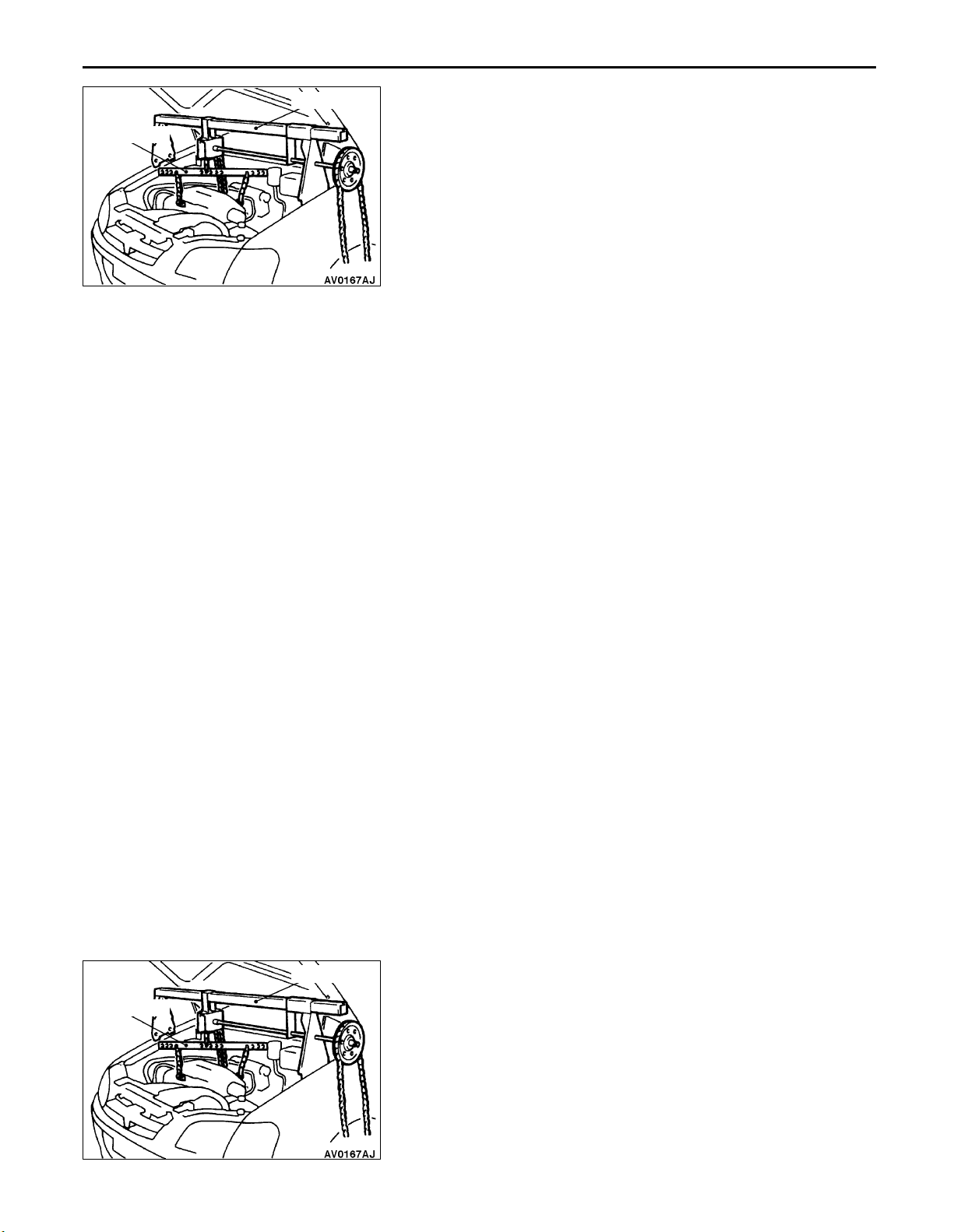
11C-24
ENGINE <F9Q1> – Engine AssemblyENGINE <F9Q1> – Engine Assembly
MB991453
MZ203827
C A/C COMPRESSOR REMOVAL
Disconnect the A/C compressor connector and remove the
compressor from the compressor bracket with the hose still
attached.
NOTE
Place the removed A/C compressor where it will not be a
hindrance when removing and installing the engine assembly,
and tie it with a cord.
D ENGINE MOUNT BRACKET REMOVAL
1. Support the engine with a garage jack.
2. Remove the special tool which was attached when the
transmission assembly was removed.
3. Hold the engine assembly with a chain block or similar
tool.
4. Place a garage jack against the engine oil pan with a
piece of wood in between, jack up the engine so that
the weight of the engine is no longer being applied to
the engine mount bracket, and then remove the engine
mount bracket.
E ENGINE ASSEMBLY REMOVAL
After checking that all cables, hoses and harness connectors,
etc., are disconnected from the engine, lift the chain block
slowly to remove the engine assembly upward from the engine
compartment.
MB991453
MZ203827
INSTALLATION SERVICE POINTS
A ENGINE ASSEMBLY INSTALLATION
Install the engine assembly, checking that the cables, hoses,
and harness connectors are not clamped.
B ENGINE MOUNT BRACKET INSTALLATION
1. Place a garage jack against the engine oil pan with a
piece of wood in between, and install the engine mount
bracket while adjusting the position of the engine.
2. Support the engine with the garage jack.
3. Remove the chain block and support the engine assembly
with the special tool.
Page 67

ENGINE
LUBRICATION
CONTENTS
12-1
GENERAL 2. . . . . . . . . . . . . . . . . . . . . . . . . . . . . . . . .
Outline of Change 2. . . . . . . . . . . . . . . . . . . . . . . . . . . .
LUBRICANT <F9QT> 2. . . . . . . . . . . . . . . . . . . . . . .
ON-VEHICLE SERVICE <F9QT> 2. . . . . . . . . . . . .
Engine Oil Inspection 2. . . . . . . . . . . . . . . . . . . . . . . . .
Engine Oil Replacement 2. . . . . . . . . . . . . . . . . . . . . . . .
Oil Filter Replacement 3. . . . . . . . . . . . . . . . . . . . . . . . .
Page 68

General/Lubricant <F9QT>/
ACEA cl
ificati
SERVICE B2-96
96
12-2
ENGINE LUBRICATION –
On-vehicle Service <F9QT>
GENERAL
OUTLINE OF CHANGE
The following service procedures have been established to correspond to the addition of the F9QT diesel
engine. Other service procedures are the same as before.
LUBRICANT <F9QT>
Items Engine oil Quantity L
Oil filter
Total quantity
Good
MIN
CCMC classification For SERVICE PD2,
ass
on For
ON-VEHICLE SERVICE <F9QT>
ENGINE OIL INSPECTION
1. Pull out the level gauge slowly and check that the oil
level is in the illustrated range.
2. Check that the oil is not excessively dirty, that there is
MAX
no coolant or gasoline mixed in, and that it has sufficient
viscosity.
0.14
or B3-
5.04
Drain plug
ENGINE OIL REPLACEMENT
1. Start the engine and allow it to warm up until the
temperature of the coolant reaches 80C to 90C.
2. Remove the engine oil filler cap.
3. Remove the under cover.
4. Remove the drain plug to drain oil.
Caution
Use care as oil could be hot.
5. Fit the drain plug after oil has been drained completely.
NOTE
Tightening torque: 25 Nm
6. Refill with specified quantity of oil.
Specified Engine Oil:
CCMC classification For SERVICE PD2
ACEA classification For SERVICE B2-96 or B3-96
Total quantity (Includes volume inside oil filter):
5.04 L
7. Install the engine oil filler cap.
8. Check oil level.
Page 69

ENGINE LUBRICATION – On-vehicle Service <F9QT>
OIL FILTER REPLACEMENT
1. After removing the engine oil filler cap, remove the engine
oil drain plug to drain the engine oil.
2. Use the oil filter wrench to remove the engine oil filter.
3. Clean the cylinder block side mounting surface.
4. Apply a small amount of engine oil to the O-ring of a
new oil filter.
5. Use the oil filter wrench to install the engine oil filter.
NOTE
Tightening torque: 10 – 14 Nm
6. Fill with engine oil.
7. Race the engine 2 – 3 times, and check to be sure that
no engine oil leaks from installation section of the oil filter.
O-ring
12-3
Page 70

NOTES
Page 71

FUEL
CONTENTS
GASOLINE DIRECT INJECTION (GDI) 13A. . . . . . . . . . . . . . . . . . . . . . . . . . . . . . . . . . .
MULTIPOINT FUEL INJECTION (MPI) 13B. . . . . . . . . . . . . . . . . . . . . . . . . . . . . . . . . . . .
FUEL SUPPLY 13C. . . . . . . . . . . . . . . . . . . . . . . . . . . . . . . . . . . . . . . . . . . . . . . . . . . . . . . . . .
13A-1
DIESEL FUEL 13D. . . . . . . . . . . . . . . . . . . . . . . . . . . . . . . . . . . . . . . . . . . . . . . . . . . . . . . . . .
Page 72

13A-2
GASOLINE DIRECT
INJECTION (GDI)
CONTENTS
GENERAL 3. . . . . . . . . . . . . . . . . . . . . . . . . . . . . . . . .
Outline of Change 3. . . . . . . . . . . . . . . . . . . . . . . . . . . .
GENERAL INFORMATION 3. . . . . . . . . . . . . . . . . .
SERVICE SPECIFICATIONS 5. . . . . . . . . . . . . . . . .
TROUBLESHOOTING 6. . . . . . . . . . . . . . . . . . . . . . .
ON-VEHICLE SERVICE 121. . . . . . . . . . . . . . . . . . .
Accelerator Pedal Position Sensor
Adjustment 121. . . . . . . . . . . . . . . . . . . . . . . . . . . . . . . .
Fuel Pressure Test 122. . . . . . . . . . . . . . . . . . . . . . . . .
Fuel Leak Check 125. . . . . . . . . . . . . . . . . . . . . . . . . .
Component Location 126. . . . . . . . . . . . . . . . . . . . . . .
Accelerator Pedal Position Sensor Check 127. . . .
Accelerator Pedal Position Switch Check 127. . . .
Oxygen Sensor Check 128. . . . . . . . . . . . . . . . . . . . .
FUEL PUMP (HIGH PRESSURE) 130. . . . . . . . . .
FUEL INJECTOR 133. . . . . . . . . . . . . . . . . . . . . . . .
THROTTLE BODY 137. . . . . . . . . . . . . . . . . . . . . . . .
Page 73

GDI – General/General Information
13A-3
GENERAL
OUTLINE OF CHANGES
Due to the changes shown below, the service procedures regarding the different description from the
previous version have been established.
On-board Diagnostics System has been adopted to expand the diagnostic items and to change diagnosis
code numbering system.
Fuel pressure regulator (high-pressure) incorporate fuel pump (high-pressure) has been adopted.
An oxygen sensor (rear) has been added.
A ignition failure sensor has been added.
Lead cables of the crank angle sensor have been contained in the timing belt cover.
An accelerator pedal position sensor attached to the accelerator pedal has been adopted.
An engine-ECU has been changed.(Change of terminal layout) <Vehicles with M/T>
An engine-A/T-ECU has been adopted. <Vehicles with A/T>
GENERAL INFORMATION
SELF-DIAGNOSIS FUNCTION
Following functions have been added.
The engine-ECU records the engine operating condition when the diagnosis code is set.
This data is called “freeze frame” data.
This data can be read by using the MUT-II, are can then be used in simulation tests for troubleshooting.
GENERAL SPECIFICATIONS
Items Specifications
Engine-ECU <M/T> Identification No. E2T72675
Engine-A/T-ECU <A/T> Identification No. E2T77572
Page 74
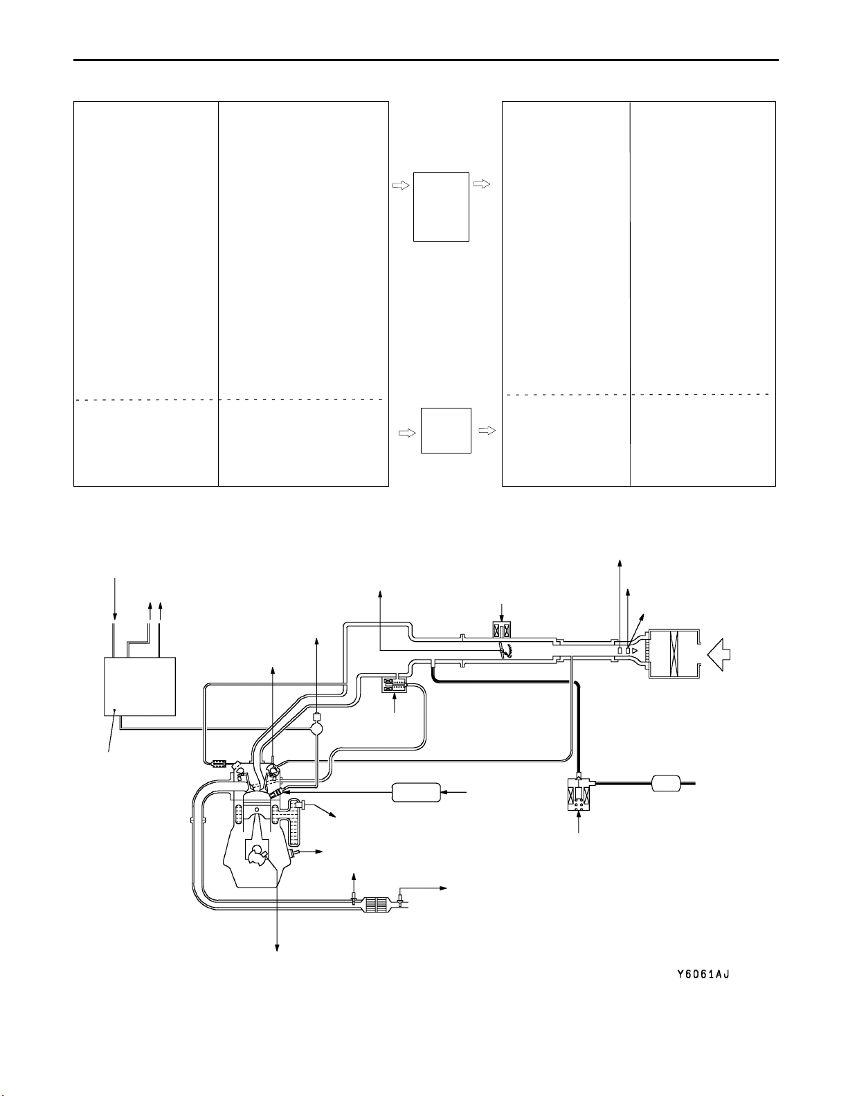
13A-4
GDI – General Information
GASOLINE DIRECT INJECTION SYSTEM DIAGRAM
1 Oxygen sensor
(front)
2 Oxygen sensor
(rear)
3 Air flow sensor
4 Intake air tempera-
ture sensor
5 Throttle position
sensor (2nd channel)
6 Camshaft position
sensor
7 Crank angle sensor
8 Barometric pres-
sure sensor
9 Engine coolant tem-
perature sensor
10 Detonation sensor
11 Fuel pressure sen-
sor
Power supply
Ignition switch-IG
Ignition switch-ST
Accelerator pedal position
sensor (1st channel)
Accelerator pedal position
switch
Vehicle speed sensor
A/C switch 1
A/C switch 2
M/T oil temperature
sensor <M/T>
Inhibitor switch <A/T>
Power steering fluid
pressure switch
Alternator FR signal
Stop lamp switch
Small lamp switch
Clutch switch <M/T>
Brake vacuum sensor
Injector open circuit check
signal
Throttle valve controller
EngineECU
<M/T> or
engineA/T-ECU
<A/T>
1 Injector driver
(injector)
2 EGR valve
(stepper motor)
3 Purge control
solenoid valve
Engine control relay
Fuel pump relay
Injector driver relay
Throttle control
servo relay
A/C relay
Ignition coil
Fan controller
Engine warning
lamp
GDI ECO indicator
lamp
Diagnosis output
Alternator G termi-
nal
Throttle valve
controller
Oxygen sensor
heater
12 Throttle position
sensor (1st channel)
From fuel pump
(low-pressure)
To fuel tank
Fuel pump
(high-pressure)
Power supply
Ignition switch-IG
Accelerator pedal position
sensor (2nd channel)
Engine-ECU <M/T>
Engine-A/T-ECU <A/T>
5 Throttle position sensor (2nd channel)
12 Throttle position sensor (1st channel)
11 Fuel pressure sensor
6 Camshaft
position sensor
10 Detonation sensor
Throttle
valve
controller
4 Throttle control servo
2 EGR valve
4 Throttle valve
Injector
1 Injector
driver
9 Engine coolant temperature sensor
1 Oxygen sensor (front)
2 Oxygen sensor (rear)
Engine-ECU<M/T>
control servo
Engine-A/T-ECU
<A/T>
4 Intake air temperature sensor
3 Air flow sensor
8 Barometric pressure
sensor
Canister
3 Purge control
solenoid valve
7 Crank angle sensor
Page 75
GDI – Service Specifications
SERVICE SPECIFICATIONS
Items Standard value
13A-5
Adjustment voltage of accelerator pedal position sensor
(1st and 2nd channel) V
Resistance of accelerator pedal position sensor
(1st and 2nd channel) kΩ
Fuel pressure
Oxygen sensor output voltage (during revving) V 0.6 – 1.0
Oxygen sensor heater resistance (at 20C) Ω
High-pressure side MPa 4 – 6.9
Low-pressure side kPa Approximately 329
Front 4.5 – 8.0
Rear 11 – 18
0.985 – 1.085
3.5 – 6.5
Page 76

13A-6
GDI – Troubleshooting
TROUBLESHOOTING
DIAGNOSIS FUNCTION
Engine warning lamp
(check engine lamp)
Engine warning lamp inspection items
Code No. Diagnosis item
– Engine-ECU <M/T> or engine-A/T-ECU <A/T>
P0100 Air flow sensor system
P0105 Barometric pressure sensor system
P0110 Intake air temperature sensor system
ENGINE WARNING LAMP (CHECK ENGINE LAMP)
If an abnormality occurs in any of the following items related
to the GDI system, the engine warning lamp will illuminate
or flash. If the lamp remains illuminated or if the lamp illuminates
while the engine is running, check the diagnosis code output.
However, the warning lamp will illuminate as bulb check for
five seconds whenever the ignition switch is turned to the
ON position.
P0115 Engine coolant temperature sensor system
P0120 Throttle position sensor (1st channel) system
P0125 Feedback system
P0130 Oxygen sensor (front) system <sensor 1>
P0135 Oxygen sensor heater (front) system <sensor 1>
P0136 Oxygen sensor (rear) system <sensor 2>
P0141 Oxygen sensor heater (rear) system <sensor 2>
P0170 Abnormal fuel system
P0190 Abnormal fuel pressure
P0201 No. 1 injector system
P0202 No. 2 injector system
P0203 No. 3 injector system
P0204 No. 4 injector system
P0220 Accelerator pedal position sensor (1st channel) system
P0225 Throttle position sensor (2nd channel) system
P0300 Ignition coil (power transistor) system
P0301 No. 1 cylinder misfire detected
P0302 No. 2 cylinder misfire detected
P0303 No. 3 cylinder misfire detected
P0304 No. 4 cylinder misfire detected
Page 77

GDI – Troubleshooting
Code No. Diagnosis item
P0335 Crank angle sensor system
P0340 Camshaft position sensor system
P0403 EGR valve system
P0420 Catalyst malfunction
P0443 Purge control solenoid valve system
P1200 Injector driver system
P1220 Electronic-controlled throttle valve system
P1221 Throttle valve position feedback system
P1223 Communication line with throttle valve controller
P1224 Throttle valve control servo motor (motor 1st phase malfunction) system
P1225 Accelerator pedal position sensor (2nd channel) system
P1228 Throttle valve control servo motor (motor 2nd phase malfunction) system
13A-7
P1515 Brake vacuum sensor system
NOTE
1. If the engine warning lamp illuminates because of a malfunction of the engine-ECU (engine-A/T-ECU),
communication between MUT-II and the engine-ECU (engine-A/T-ECU) is impossible. In this case,
the diagnosis code cannot be read.
2. After the engine-ECU (engine-A/T-ECU) has detected a malfunction, the engine warning lamp illuminates
when the engine is next turned on and the same malfunction is re-detected. However, for items marked
with a “” in the diagnosis code number column, the engine warning lamp illuminates only on the
first detection of the malfunction.
As for P1220, P1221, P1223, P1224, and P1228, the engine warning lamp flashes. If malfunctions
are detected at the throttle position sensor (1st channel) and the throttle position sensor (2nd channel)
at the same time, or malfunctions are detected at the accelerator pedal position sensor (1st channel)
and the accelerator pedal position sensor (2nd channel) at the same time, the engine warning lamp
will flash.
3. After the engine warning lamp illuminates, it will be switched off under the following conditions.
(1) When the engine-ECU (engine-A/T-ECU) monitored the power train malfunction three times* and
met set condition requirements, it detected no malfunction.
*: In this case, “one time” indicates from engine start to stop.
(2) For misfiring malfunction, when driving conditions (engine speed, engine coolant temperature, etc.)
are similar to those when the malfunction was first recorded.
4. Sensor 1 indicates the sensor mounted at a position closest to the engine, and sensor 2 indicates
the sensor mounted at the position second closest to the engine.
Page 78

13A-8
GDI – Troubleshooting
METHOD OF READING AND ERASING DIAGNOSIS
CODES
Refer to GROUP 00 – How to Use Troubleshooting/Inspection
Service Points.
DIAGNOSIS USING DIAGNOSIS 2 MODE
1. Switch the diagnosis mode of the engine control unit to
DIAGNOSIS 2 mode using the MUT-II.
2. Carry out a road test.
3. Take a reading of the diagnosis code and repair the problem
location.
4. Turn the ignition switch to OFF and then back to ON again.
NOTE
By turning the ignition switch to OFF, the engine-ECU
<M/T> or engine-A/T-ECU <A/T> will switch the diagnosis
mode from DIAGNOSIS 2 mode to DIAGNOSIS 1 mode.
5. Erase the diagnosis codes.
INSPECTION USING MUT-II DATA LIST AND
ACTUATOR TESTING
1. Carry out inspection by means of the data list and the
actuator test function. If there is an abnormality, check
and repair the chassis harnesses and components.
2. After repairing, re-check using the MUT-II and check that
the abnormal input and output have returned to normal
as a result of the repairs.
3. Erase the diagnosis code memory.
4. Remove the MUT-II, and then start the engine again and
carry out a road test to confirm that the problem has
disappeared.
Page 79

GDI – Troubleshooting
ti
FREEZE FRAME DATA
When the engine-ECU <M/T> or engine-A/T-ECU <A/T>
detects a malfunction and stores a diagnosis code, it also
stores a current status of the engine. This function is called
“Freeze frame data.” By analyzing this “freeze frame” data
with the MUT-II, an effective troubleshooting can be performed.
The display items of freeze frame data are shown below.
Display item list
Data item Unit
Engine coolant temperature sensor C
Engine speed r/min
Vehicle speed km/h
13A-9
Long-term fuel compensation (long-term
fuel trim)
Short-term fuel compensation (short-term
fuel trim)
Fuel control condi-
on
Calculation load value %
Diagnosis code during data recording –
Open loop OL
Closed loop CL
Open loop owing to
drive condition
Open loop owing to
system malfunction
Closed loop based
on one oxygen sensor
%
%
OL-DRV.
OL-SYS.
CL-H02S
NOTE
If malfunctions have been detected in multiple systems, store
one malfunction only, which has been detected first.
READINESS TEST STATUS
The engine-ECU <M/T> or engine-A/T-ECU <A/T> monitors
the following main diagnosis items, judges if these items are
in good condition or not, and the stores its history. This history
can be read out by using MUT-II. (If the ECU has judged
a item before, the MUT-II displays “Complete.”)
In addition, if diagnosis codes are erased or the battery cable
is disconnected, this history will also be erased (the memory
will be reset).
Catalyst: P0420
Oxygen sensor: P0130
Oxygen sensor heater: P0135, P0141
Page 80

13A-10
GDI – Troubleshooting
FAIL-SAFE FUNCTION REFERENCE TABLE
When the main sensor malfunctions are detected by the diagnosis function, the vehicle is controlled by
means of the pre-set control logic to maintain safe conditions for driving.
Malfunctioning item Control contents during malfunction
Air flow sensor 1. Suspends lean burn operation.
2. Uses the throttle position sensor signal and engine speed signal (crank angle
sensor signal) to take reading of the basic injector drive time and basic ignition
timing from the pre-set mapping.
Intake air temperature sensor Controls as if the intake air temperature is 25C.
Throttle position sensor (2nd
channel)
Engine coolant temperature
sensor
Camshaft position sensor Controls maintaining the condition before determined as failure.
Vehicle speed sensor 1. Suspends lean burn operation. However, the control is cancelled as a certain
Barometric pressure sensor Controls as if the barometric pressure is 101 kPa.
Detonation sensor Fixes the ignition timing as that for standard petrol.
Injector 1. Suspends lean burn operation.
Ignition coil (incorporating power transistor)
1. Suspends lean burn operation.
2. Controls the throttle opening angle feedback (half as much as the opening
rate in the normal condition) by using signals from the throttle position sensor
(1st channel). However, this controlling system is not applied if the throttle
position sensor (1st channel) and throttle position sensor (2nd channel)
combination output voltage is outside 4 – 6 V.
3. Refrains from controlling the throttle opening angle feedback if the throttle
position sensor (1st channel) is also defective.
Controls as if the engine coolant temperature is 80C. (Moreover, the control system
is working until the ignition switch is turned OFF if the sensor signal returns to normal.)
Fuel will be cut-off 4 seconds after a malfunction is detected. (However, only if
No. 1 cylinder TDC has never been detected after the ignition switch is turned
to the ON position)
time passes by with the engine speed of 1,500 r/min or more.
2. Suspends lean burn operation during the engine idling.
2. Suspends the exhaust gas recirculation.
1. Suspends lean burn operation.
2. Cuts off the fuel supply to cylinders with an abnormal ignition signal.
Fuel pressure sensor 1. Controls as if the fuel pressure is 5 MPa. (In case of open/short circuit)
2. Turns the fuel pump relay off. (In case of abnomality in high pressure)
3. Suspends fuel injection. (when the low pressure is detected and the engine
speed is more than 3,000 r/min)
Alternator FR terminal Refrains from controlling to suppress the alternator output to electrical load.
(Operated as a normal alternator)
Accelerator pedal position sensor (2nd channel)
1. Suspends lean burn operation.
2. Controls the throttle valve position by using signals from the accelerator pedal
position sensor (1st channel). (However, the control system is not applicable
if the difference from the accelerator pedal position sensor (1st channel) output
voltage is 1.0 V or higher.)
3. Suspends the electronic controlled throttle valve system if accelerator pedal
position sensor (1st channel) is also defective.
Page 81

GDI – Troubleshooting
Malfunctioning item Control contents during malfunction
13A-11
Accelerator pedal position sensor (1st channel)
Throttle position sensor (1st
channel)
Electronic-controlled throttle
valve system
Throttle valve position feedback
Communication line between
the throttle valve controller and
the engine-ECU <M/T> or
engine-A/T-ECU <A/T>
1. Suspends lean burn operation.
2. Controls the throttle valve position by using signals from the accelerator pedal
position sensor (2nd channel). (However, this control is not applicable if the
voltage difference between the accelerator pedal position sensor (1st channel)
and accelerator pedal position sensor (2nd channel) is 1.0 V or higher.)
3. Also suspends the electronic-controlled throttle valve system when the
accelerator pedal position sensor (2nd channel) is defective.
1. Suspends lean burn operation.
2. Controls throttle opening angle feedback by using signals from throttle position
sensor (2nd channel). (However, the controlling system is not applied when
the throttle position sensor (1st channel) and throttle position sensor (2nd
channel) combination output voltage is outside 4 – 6 V.)
3. Refrains from controlling the throttle opening angle feedback when throttle
position sensor (2nd channel) is also defective.
1. Suspends the electronic controlled throttle valve system.
2. Suspends lean burn operation.
3. Suspends the idle speed feedback control.
1. Suspends the electronic controlled throttle valve system.
2. Suspends lean burn operation.
3. Suspends the engine speed feedback control.
1. Communication error between the throttle valve controller and the engine-ECU
<M/T> or engine-A/T-ECU <A/T>:
Suspends lean burn operation.
Cuts the fuel supply when the engine speed reaches 3,000 r/min or more.
Suspends the cruise-control.
2. Communication error between the throttle valve controller and the engine-ECU
<M/T> or engine-A/T-ECU <A/T>:
Suspends lean burn operation.
Cuts the fuel supply when the engine speed reaches 3,000 r/min or more.
Suspends the cruise-control.
The throttle valve controller controls the throttle valve opening angle by
using signals from accelerator pedal position sensor (2nd channel).
Throttle control servo motor 1st
phase malfunction
Throttle control servo motor
2nd phase malfunction
Misfiring If the detected misfiring causes damage to the catalyst, the misfiring cylinder will be
Bans lean burn operation.
1. Suspends electronic control throttle valve system.
2. Bans lean burn operation.
3. Bans engine speed feed back control.
shut down.
NOTE
If the electronic-controlled throttle valve system is suspended, the engine warning lamp will illuminate.
Page 82

13A-12
GDI – Troubleshooting
INSPECTION CHART FOR DIAGNOSIS CODES
Code No. Diagnosis item Reference page
P0100 Air flow sensor system 13A-14
P0105 Barometric pressure sensor system 13A-16
P0110 Intake air temperature sensor system 13A-18
P0115 Engine coolant temperature sensor system 13A-19
P0120 Throttle position sensor 1 (1st channel) system 13A-22
P0125 Feedback system 13A-24
P0130 Oxygen sensor (front) system <sensor 1> 13A-26
P0135 Oxygen sensor heater (front) system <sensor 1> 13A-28
P0136 Oxygen sensor (rear) system <sensor 2> 13A-29
P0141 Oxygen sensor heater (rear) system <sensor 2> 13A-31
P0170 Abnormal fuel system 13A-32
P0190 Abnormal fuel pressure 13A-34
P0201 No. 1 injector system 13A-35
P0202 No. 2 injector system 13A-37
P0203 No. 3 injector system 13A-38
P0204 No. 4 injector system 13A-39
P0220 Accelerator pedal position sensor (1st channel) system 13A-41
P0225 Throttle position sensor (2nd channel) system 13A-44
P0300 Ignition coil (power transistor) system 13A-45
P0301 No. 1 cylinder misfire detected 13A-47
P0302 No. 2 cylinder misfire detected 13A-47
P0303 No. 3 cylinder misfire detected 13A-47
P0304 No. 4 cylinder misfire detected 13A-47
P0325 Detonation sensor system 13A-48
P0335 Crank angle sensor system 13A-48
P0340 Camshaft position sensor system 13A-50
P0403 EGR valve system 13A-52
P0420 Catalyst malfunction 13A-54
P0443 Purge control solenoid valve system 13A-55
P0500 Vehicle speed sensor system 13A-56
P1200 Injector driver system 13A-56
P1220 Electronic-controlled throttle valve system 13A-57
Page 83

GDI – Troubleshooting
Code No. Reference pageDiagnosis item
P1221 Throttle valve position feedback system 13A-58
P1223 Communication line with throttle valve controller 13A-59
P1224 Throttle valve control servo motor (motor 1st phase malfunction) system 13A-60
P1225 Accelerator pedal position sensor (2nd channel) system 13A-61
P1228 Throttle valve control servo motor (motor 2nd phase malfunction) system 13A-63
P1500 Alternator FR terminal system 13A-64
P1515 Brake vacuum sensor system 13A-65
P1610 Immobilizer system 13A-67
13A-13
NOTE
1. Do not replace the engine-ECU <M/T> or engine-A/T-ECU <A/T> until a through terminal check reveals
there are no short/open circuit.
2. Check that the engine-ECU <M/T> or engine-A/T-ECU <A/T> earth circuit is normal before checking
for the cause of the problem.
3. After the engine-ECU <M/T> or engine-A/T-ECU <A/T> has detected a malfunction, a diagnosis code
is recorded the next time the engine is started and the same malfunction is re-detected. However,
for items marked with a “”, the diagnosis code is recorded on the first detection of the malfunction.
4. Sensor 1 indicates the sensor mounted at a position closest to the engine, and sensor 2 indicates
the sensor mounted at the position second closest to the engine.
Page 84

13A-14
GDI – Troubleshooting
INSPECTION PROCEDURE CLASSIFIED BY DIAGNOSIS CODE
Code No. P0100 Air flow sensor system Probable cause
Range of Check
Engine speed: 500 r/min or more
Set Conditions
The sensor output frequency is 3.3 Hz or less for four seconds.
Malfunction of air flow sensor
Open or short circuit in air flow sensor circuit or
loose connector contact
Malfunction of engine-ECU <M/T>
Malfunction of engine-A/T-ECU <A/T>
MUT-II Data list
12 Air flow sensor (Refer to
P.13A-99, DATA LIST REFERENCE
TABLE.)
NG
Check the following connector:
A-73
OK
Measure at air flow sensor
connector A-73.
Disconnect the connector and
measure at the harness side.
(1) Voltage between terminal 3 and
earth (Ignition switch: ON)
OK: 4.8 – 5.2 V
(2) Voltage between terminal 4 and
earth (Ignition switch: ON)
OK: System voltage
(3) Resistance between terminal 5
and earth
OK: 2 Ω or less
OK
OK
NG
(1) NG
(2) NG
(3) NG
Transient malfunction
(Refer to GROUP 00 – Points to
Note for Intermittent Malfunctions.)
Repair
Measure at engine-ECU connector
B-86 <M/T> or engine-A/T-ECU
connector B-85 <A/T>.
Measure the voltage at the
engine-ECU terminal <M/T> or
engine-A/T-ECU terminal <A/T>.
Ignition switch: ON
Voltage between terminal 61
<M/T>, 65 <A/T> and earth
OK: 4.8 – 5.2 V
NG
Check the following connectors:
B-86 <M/T>, B-85 <A/T>
OK
Check the harness between the air
flow sensor and the engine-ECU
<M/T> or engine-A/T-ECU <A/T>.
OK
Check the trouble symptoms.
Check the following connector:
B-26
OK
Check the harness between the air
flow sensor and the engine control
relay, and repair if necessary.
Check the following connectors:
B-87 <M/T>, B-86 <A/T>
OK
Check the harness between the air
flow sensor and the engine-ECU
<M/T> or engine-A/T-ECU <A/T>.
OK
Check the trouble symptoms.
OK
NG
NG
NG
NG
NG
NG
NG
Check the following connectors:
B-86 <M/T>, B-85 <A/T>
OK
Check the harness between the air
flow sensor and the engine-ECU
<M/T> or engine-A/T-ECU <A/T>,
and repair if necessary.
Repair
Repair
Replace the engine-ECU <M/T> or
engine-A/T-ECU <A/T>.
Repair
Repair
Repair
Replace the engine-ECU <M/T> or
engine-A/T-ECU <A/T>.
NG
Repair
To the next page
Page 85

From the previous page
OK
Measure at air flow sensor
connector A-73.
Use test harness (MB991709) to
connect the connector, and
measure at the pick-up harness.
Ignition switch: ON
Voltage between terminal 7 and
earth
OK: 7 – 8 V
OK
NG
GDI – Troubleshooting
Check the following connectors:
B-87 <M/T>, B-84 <A/T>
OK
Check the harness between the air
flow sensor and the engine-ECU
<M/T> or engine-A/T-ECU <A/T>.
OK
Replace the air flow sensor.
NG
NG
13A-15
Repair
Repair
Measure at air flow sensor
connector A-73.
Use test harness (MB991709) to
connect the connector, and
measure at the pick-up harness.
Selector lever position: P
Voltage between terminal 7 and
earth
OK: Engine: Idling
0 – 1 V
Engine speed: 3,000 r/min
6 – 9 V
OK
Measure the output wave form at
air flow sensor connector A-73 (by
using an analyzer).
Use test harness (MB991709) to
connect the connector, and
measure at the pick-up harness.
Engine: Idling
Voltage between terminal 3 and
earth
OK: Waveforms should be dis-
played on P.13A-118 (Inspection Procedure Using
an Analyzer) and noise
should not be displayed in
the waveform.
OK
NG
NG
Check the following connectors:
B-87 <M/T>, B-84 <A/T>
OK
Check the harness between the air
flow sensor and the engine-ECU
<M/T> or engine-A/T-ECU <A/T>.
OK
Check the trouble symptoms.
NG
Replace the engine-ECU <M/T> or
engine-A/T-ECU <A/T>.
Replace the air flow sensor.
Check the trouble symptoms.
NG
Check the following connectors:
B-86 <M/T>, B-85 <A/T>
Check the harnesses between the
air flow sensor and the engine-ECU
<M/T> or engine-A/T-ECU <A/T>
and between the air flow sensor
and the engine control relay, and
repair if necessary.
OK
OK
NG
NG
NG
Repair
Repair
Repair
Check the trouble symptoms.
NG
Replace the engine-ECU <M/T> or
engine-A/T-ECU <A/T>.
Page 86

13A-16
GDI – Troubleshooting
Code No. P0105 Barometric pressure sensor system Probable cause
Range of Check
Two seconds have passed since the ignition switch is turned ON or the
engine starting process is completed.
Battery voltage: 8 V or more
Set Conditions
The sensor output voltage is 4.5 V or more for four seconds (equivalent to
114 kPa of barometric pressure)
or
The sensor output voltage is 0.2 V or less (equivalent to 53 kPa of
barometric pressure)
Malfunction of barometric pressure sensor
Open or short circuit in barometric pressure
sensor circuit or loose connector contact
Malfunction of engine-ECU <M/T>
Malfunction of engine-A/T-ECU <A/T>
MUT-II Data list
25 Barometric pressure sensor
(Refer to P.13A-99, DATA LIST
REFERENCE TABLE.)
NG
Check the following connector:
A-73
OK
Measure at air flow sensor
connector A-73.
Disconnect the connector and
measure at the harness side.
(1) Voltage between terminal 1 and
earth (Ignition switch: ON)
OK: 4.8 – 5.2 V
(2) Resistance between terminal 5
and earth
OK: 2 Ω or less
OK
To the next page
OK
NG
(1) NG
(2) NG
Transient malfunction
(Refer to GROUP 00 – Points to
Note for Intermittent Malfunctions.)
Repair
Measure at engine-ECU connector
B-86 <M/T> or engine-A/T-ECU
connector B-86 <A/T>.
Measure the voltage at the
engine-ECU terminal <M/T> or
engine-A/T-ECU terminal <A/T>.
Ignition switch: ON
Voltage between terminal 41
<M/T>, 87 <A/T> and earth
OK: 4.8 – 5.2 V
NG
Check the following connector:
B-86
OK
Check the harness between the air
flow sensor and the engine-ECU
<M/T> or engine-A/T-ECU <A/T>.
OK
Check the trouble symptoms.
Check the following connectors:
B-87 <M/T>, B-86<A/T>
OK
Check the harness between the air
flow sensor and the engine-ECU
<M/T> or engine-A/T-ECU <A/T>.
OK
Check the trouble symptoms.
NG
NG
NG
NG
NG
NG
OK
Check the following connector:
B-86
OK
Check the harness between the air
flow sensor and the engine-ECU
<M/T> or engine-A/T-ECU <A/T>,
and repair if necessary.
Repair
Repair
Replace the engine-ECU <M/T> or
engine-A/T-ECU <A/T>.
Repair
Repair
Replace the engine-ECU <M/T> or
engine-A/T-ECU <A/T>.
NG
Repair
Page 87

From the previous page
OK
Measure at air flow sensor
connector A-73.
Connect connector terminals No.
1, No. 2 and No. 5 only by
using test harness (MB991709),
and measure at the pick-up
harness.
Ignition switch: ON
(1) Voltage between terminal 1 and
earth
OK: 4.8 – 5.2 V
(2) Voltage between terminal 2 and
earth
OK: Altitude 0 m: 3.7 – 4.3 V
Altitude 1,200 m:
3.2 – 3.8 V
(3) Voltage between terminal 5 and
earth
OK: 0.5 V or less
OK
(1) NG
(2) NG
(3) NG
GDI – Troubleshooting
Check the following connector:
B-86
OK
Check the harness between the air
flow sensor and the engine-ECU
<M/T> or engine-A/T-ECU <A/T>,
and repair if necessary.
Replace the air flow sensor.
Check the trouble symptoms.
NG
Check the following connectors:
B-86 <M/T>, B-85 <A/T>
OK
Check the harness between the air
flow sensor and the engine-ECU
<M/T> or engine-A/T-ECU <A/T>,
and repair if necessary.
NG
NG
13A-17
Repair
Repair
Measure at engine-ECU connector
B-86 <M/T> or engine-A/T-ECU
connector B-85 <A/T>.
Measure the voltage at the
engine-ECU terminal <M/T> or
engine-A/T-ECU terminal <A/T>.
Ignition switch: ON
Voltage between terminal 51
<M/T>, 65 <A/T> and earth
OK: Altitude 0 m: 3.7 – 4.3 V
Altitude 1,200 m:
3.2 – 3.8 V
NG
OK
Check the following connectors:
B-87 <M/T>, B-86 <A/T>
OK
Check the harness between the air
flow sensor and the engine-ECU
<M/T> or engine-A/T-ECU <A/T>,
and repair if necessary.
Check the following connectors:
B-86 <M/T>, B–85<A/T>
OK
Check the harness between the air
flow sensor and the engine-ECU
<M/T> or engine-A/T-ECU <A/T>,
and repair if necessary.
Check the following connectors:
B-86 <M/T>, B-87<A/T>
OK
Check the trouble symptoms.
NG
Replace the engine-ECU <M/T> or
engine-A/T-ECU <A/T>.
NG
NG
NG
Repair
Repair
Repair
Page 88

13A-18
GDI – Troubleshooting
Code No. P0110 Intake air temperature sensor system Probable cause
Range of Check
Two seconds have passed since the ignition switch is turned ON or the
engine starting process is completed.
Set Conditions
The sensor output voltage is 4.6 V or more for four seconds (equivalent to
–45C of intake air temperature)
or
The sensor output voltage is 0.2 V or more for four seconds (equivalent to
125C of intake air temperature)
Malfunction of intake air temperature sensor
Open or short circuit in intake air temperature
sensor or loose connector contact
Malfunction of engine-ECU <M/T>
Malfunction of engine-A/T-ECU <A/T>
MUT-II Data list
13 Intake air temperature sensor
OK: Roughly the same as am-
bient temperature.
NG
Check the intake air temperature
sensor itself.
(Refer to P.13A-105*.)
OK
Check following connector: A-73
OK
Measure at air flow sensor
connector A-73.
Disconnect the connector and
measure at the harness side.
(1) Resistance between terminal 5
and earth
OK: 2 Ω or less
(2) Voltage between terminal 6 and
earth
(Ignition switch: ON)
OK: 4.8 – 5.2 V
OK
NG
NG
(1) NG
(2) NG
Transient malfunction
(Refer to GROUP 00 – Points to
Note for Intermittent Malfunctions.)
Repair
Repair
Check the following connectors:
B-87 <M/T>, B-86 <A/T>
OK
Check the harness between the air
flow sensor and the engine-ECU
<M/T> or engine-A/T-ECU <A/T>.
OK
Check the trouble symptoms.
Measure at engine-ECU connector
B-86 <M/T> or engine-A/T-ECU
connector B-85 <A/T>.
Measure the voltage at the
engine-ECU terminal <M/T> or
engine-A/T-ECU terminal <A/T>.
Disconnect connector A-73.
Ignition switch: ON
Voltage between terminal 62
<M/T>, 64 <A/T> and earth
OK: 4.8 – 5.2 V
NG
NG
NG
NG
OK
Repair
Repair
Replace the engine-ECU <M/T> or
engine-A/T-ECU <A/T>.
Check the following connectors:
B-86 <M/T>, B-85 <A/T>
OK
Check the harness between the air
flow sensor and the engine-ECU
<M/T> or engine-A/T-ECU <A/T>,
and repair if necessary.
NG
Repair
Check the following connectors:
B-86 <M/T>, B-85 <A/T>
OK
OK
Check the harness between the air
flow sensor and the engine-ECU
<M/T> or engine-A/T-ECU <A/T>.
OK
Check the trouble symptoms.
To the next page
NG
NG
NG
Repair
Repair
Replace the engine-ECU <M/T> or
engine-A/T-ECU <A/T>.
NOTE
*: Refer to the ’99 SPACE STAR Workshop Manual (Pub. No. CMXE99E1).
Page 89

From the previous page
OK
Measure at air flow sensor
connector A-73.
Use the test harness
(MB991709) to connect only
terminals 5 and 6, and then
measure at the pick-up harness.
Ignition switch: ON
Voltage between terminal 6 and
earth
OK: Ambient temperature 0C:
3.2 – 3.8 V
Ambient temperature 20C:
2.3 – 2.9 V
Ambient temperature 40C:
1.5 – 2.1 V
Ambient temperature 80C:
0.4 – 1.0 V
OK
Check the trouble symptoms.
NG
NG
GDI – Troubleshooting
Check the following connectors:
B-86, B-87 <M/T>, B-85, B-86 <A/T>
OK
Check the harness between the air
flow sensor and the engine-ECU
<M/T> or engine-A/T-ECU <A/T>,
and repair if necessary.
Replace the engine-ECU <M/T> or
engine-A/T-ECU <A/T>.
NG
13A-19
Repair
Code No. P0115 Engine coolant temperature sensor
system
Range of Check
Engine: Two seconds after the engine has been started
Set Conditions
The sensor output voltage is 4.6 V or more for four seconds (equivalent to
–45C of engine coolant temperature)
or
The sensor output voltage is 0.1 V or less for four seconds (equivalent to
140C of engine coolant temperature)
Range of Check
Engine: After starting
Set Conditions
The engine coolant temperature has reduced from over 40C to less than
40C, and that condition has lasted for five minutes or more.
Probable cause
Malfunction of engine coolant temperature sensor
Open or short circuit in the engine coolant
temperature sensor circuit or loose connector
contact
Malfunction of engine-ECU <M/T>
Malfunction of engine-A/T-ECU <A/T>
Page 90
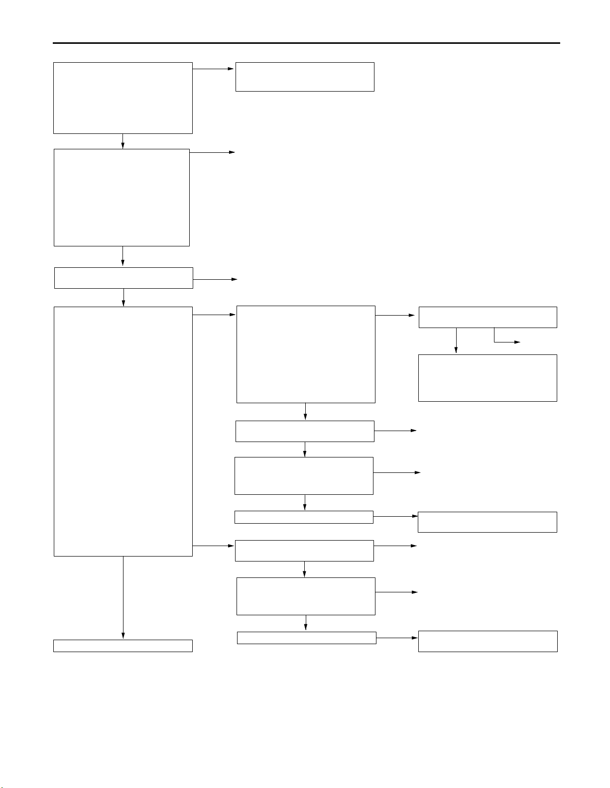
13A-20
GDI – Troubleshooting
MUT-II Data list
21 Engine coolant temperature
sensor
OK: When the engine is cold,
the temperature is roughly
the same as ambient temperature. If warm, it is 80
– 120C.
NG
Measure at engine coolant
temperature sensor connector A-76.
Disconnect the connector and
measure at the harness side.
Resistance between terminals 1
and 2
OK: At 20C of engine coolant
temperature: 2.1 – 2.7 kΩ
At 80C of engine coolant
temperature: 0.26 – 0.36
kΩ
OK
Check the following connector:
A-76
OK
Measure at engine coolant
temperature sensor connector A-76.
Disconnect the connector and
measure at the harness side.
(1) Voltage between terminal 1 and
earth
(Ignition switch: ON)
OK: 4.8 – 5.2 V
(2) Resistance between terminal 2
and earth
OK: 2 Ω or less
OK
To the next page
OK
NG
NG
(1) NG
(2) NG
Transient malfunction
(Refer to GROUP 00 – Points to
Note for Intermittent Malfunctions.)
Replace
Repair
Measure at engine-ECU connector
B-86 <M/T> or engine-A/T-ECU
connector B-85 <A/T>.
Measure the voltage at the
engine-ECU terminal <M/T> or
engine-A/T-ECU terminal <A/T>.
Disconnect connector A-76.
Ignition switch: ON
Voltage between terminal 44 and
earth
OK: 4.8 – 5.2 V
NG
Check the following connectors:
B-86 <M/T>, B-85 <A/T>
OK
Check the harness wire between
the engine coolant temperature
sensor and the engine-ECU <M/T>
or engine-A/T-ECU <A/T>.
OK
Check the trouble symptoms.
Check the following connectors:
B-87 <M/T>, B-86 <A/T>
OK
Check the harness wire between
the engine coolant temperature
sensor and the engine-ECU <M/T>
or engine-A/T-ECU <A/T>.
OK
Check the trouble symptoms.
NG
NG
NG
NG
OK
NG
NG
Check the following connector:
B-86 <M/T>, B-85 <A/T>
OK
Check the harness wire between
the engine coolant temperature
sensor and the engine-ECU <M/T>
or engine-A/T-ECU <A/T>, and
repair if necessary.
Repair
Repair
Replace the engine-ECU <M/T> or
engine-A/T-ECU <A/T>.
Repair
Repair
Replace the engine-ECU <M/T> or
engine-A/T-ECU <A/T>.
NG
Repair
Page 91

GDI – Troubleshooting
From the previous page
OK
Measure at engine coolant
temperature sensor connector A-76.
Use test harness (MB991658) to
connect the connector, and
measure at the pick-up harness.
Ignition switch: ON
Voltage between terminal 1 and
earth
OK: At 0C of engine coolant
temperature: 3.2 – 3.8 V
At 20C of engine coolant
temperature: 2.3 – 2.9 V
At 40C of engine coolant
temperature: 1.3 – 1.9 V
At 80C of engine coolant
temperature: 0.3 – 0.9 V
OK
Check the trouble symptoms.
NG
NG
Check the engine coolant
temperature sensor.
(Refer to P.13A-106*.)
OK
Check the following connectors:
B-86, B-87 <M/T>, B-85, B-86 <A/T>
OK
Check the harness wire between
the engine coolant temperature
sensor and the engine-ECU <M/T>
or engine-A/T-ECU <A/T>, and
repair if necessary.
Replace the engine-ECU <M/T> or
engine-A/T-ECU <A/T>.
NOTE
*: Refer to the ’99 SPACE STAR Workshop Manual (Pub. No. CMXE99E1).
NG
NG
Repair
Repair
13A-21
Page 92

13A-22
GDI – Troubleshooting
Code No. P0120 Throttle position sensor (1st channel)
system
The throttle valve controller judges a malfunction, and then transmit the result
to the engine-ECU <M/T> or engine-A/T-ECU <A/T>.
Range of Check
Ignition switch: ON
Set Conditions
The sensor output voltage is 0.2 V or less.
or
The sensor output voltage is 4.9 V or more.
or
The throttle position sensor (1st channel) and throttle position sensor (2nd
channel) combination output voltage is outside 4 – 6 V.
or
The output voltage of the throttle position sensor (1st channel) is
significantly different (approx. 1V) from the throttle valve opening angle
(voltage), whitch the engine-ECU <M/T> or engine-A/T-ECU <A/T> request
the throttle valve controller.
MUT-II Data list
79 Throttle position sensor (1st
channel) (Refer to P.13A-99,
DATA LIST REFERENCE
TABLE.)
NG
Check the throttle position sensor.
(Refer to P.13A-106*.)
OK
Check the following connector:
A-66
OK
Measure at throttle position sensor
connector A-66.
Disconnect the connector and
measure at the harness side.
(1) Voltage between terminal 1 and
earth
(Ignition switch: ON)
OK: 4.8 – 5.2 V
(2) Resistance between terminal 3
and earth
OK: 2 Ω or less
OK
To the next page
OK
NG
NG
(1) NG
(2) NG
Transient malfunction
(Refer to GROUP 00 – Points to
Note for Intermittent Malfunctions.)
Replace
Repair
Measure at throttle valve controller
connector B-15.
Measure voltage at the throttle
valve controller connector
terminals.
Ignition switch: ON
Voltage between terminal 6 and
earth
OK: 4.8 – 5.2 V
NG
Check the following connector:
B-15
OK
Check the harness wire between
the throttle position sensor and the
throttle valve controller.
OK
Check the trouble symptoms.
Check the following connector:
B-15
OK
Check the harness wire between
the throttle position sensor and the
throttle valve controller.
OK
Check the trouble symptoms.
Probable cause
Malfunction of throttle position sensor
Open or short circuit in the throttle position
sensor (1st channel) circuit or loose connector
contact
Malfunction of throttle valve controller
Malfunction of engine-ECU <M/T>
Malfunction of engine-A/T-ECU <A/T>
OK
NG
NG
NG
NG
NG
NG
Check the following connector:
B-15
OK
Check the harness wire between
the throttle position sensor and the
throttle valve controller, and repair if
necessary.
Repair
Repair
Replace the throttle valve controller.
Repair
Repair
Replace the throttle valve controller.
NG
Repair
NOTE
*: Refer to the ’99 SPACE STAR Workshop Manual (Pub. No. CMXE99E1)
Page 93
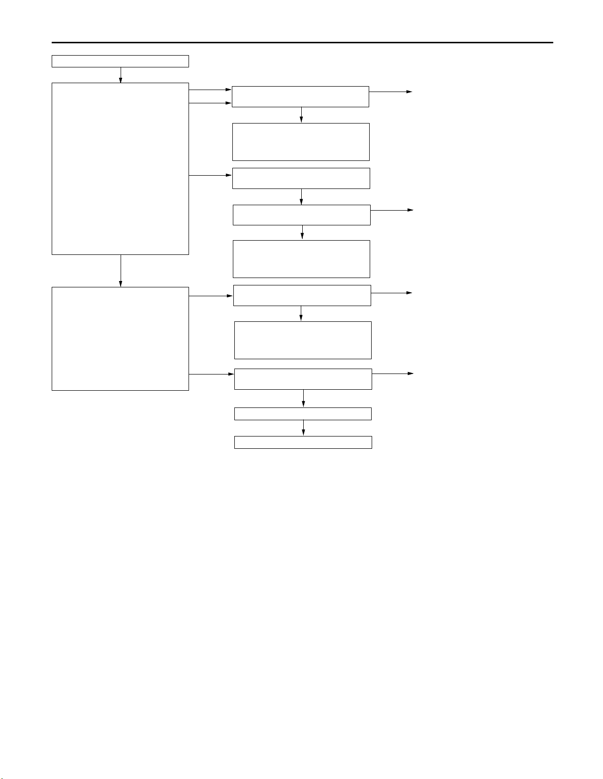
From the previous page
OK
Measure at throttle position sensor
connector A-66.
Use test harness (MB991536) to
connect the connector, and
measure at the pick-up harness.
Ignition switch: ON
(1) Voltage between terminal 1 and
earth
OK: 4.8 – 5.2 V
(2) Voltage between terminal 2 and
earth
OK: Accelerator pedal fully re-
leased: 0.4 – 0.8 V
Accelerator pedal fully depressed: 4.2 – 4.8 V
(3) Voltage between terminal 3 and
earth
OK: 0.5 V or less
OK
Measure at throttle valve controller
connector B-15.
Measure voltage at the throttle
valve controller connector
terminals.
Ignition switch: ON
Voltage between terminal 7 and
earth
OK: Accelerator pedal fully re-
leased: 0.4 – 0.8 V
Accelerator pedal fully depressed: 4.2 – 4.8 V
(1) NG
(3) NG
(2) NG
NG
OK
GDI – Troubleshooting
Check the following connector:
B-15
OK
Check the harness wire between
the throttle position sensor and the
throttle valve controller, and repair if
necessary.
Adjust the throttle position sensor.
(Refer to P.13A-96*.)
Check the following connector:
B-15
OK
Check the harness wire between
the throttle position sensor and the
throttle valve controller, and repair if
necessary.
Check the following connector:
B-15
OK
Check the harness wire between
the throttle position sensor and the
throttle valve controller, and repair if
necessary.
Check the following connector:
B-15
OK
NG
NG
NG
NG
13A-23
Repair
Repair
Repair
Repair
Check the trouble symptoms.
NG
Replace the throttle valve controller.
NOTE
*: Refer to the ’99 SPACE STAR Workshop Manual (Pub. No. CMXE99E1)
Page 94

13A-24
GDI – Troubleshooting
Code No. P0125 Feedback system Probable cause
Range of Check
The engine coolant temperature is approx. 80C or more.
During stoichiometric feedback control
The vehicle is not being decelerated.
Set Conditions
Oxygen sensor (front) output voltage has been higher or lower than 0.5 V
for at least thirty seconds.
Malfunction of oxygen sensor (front)
Open or short circuit in the oxygen sensor (front)
circuit or loose connector contact
Malfunction of engine-ECU <M/T>
Malfunction of engine-A/T-ECU <A/T>
Page 95
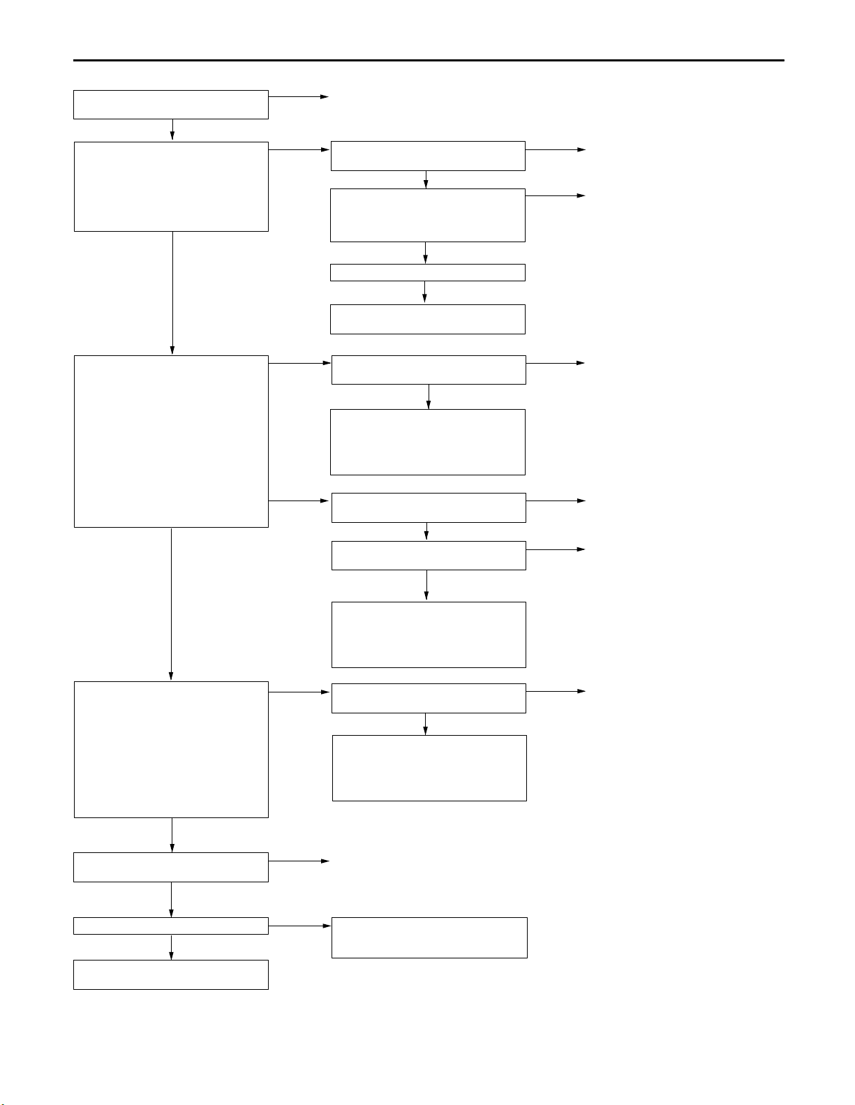
GDI – Troubleshooting
13A-25
Check the following connector:
A-55
OK
Measure at oxygen sensor (front)
connector A-55.
Disconnect the connector and
measure at the harness side.
Resistance between terminal 2
and earth
OK: 2 Ω or less
OK
Measure at oxygen sensor (front)
connector A-55.
Use the test harness
(MD998464) to connect the
connector, and measure at the
pick-up harness side.
Engine: 2,500 r/min (after
warming up)
(1) Voltage between terminal 2 and
earth
OK: 0.5 V or less
(2) Voltage between terminal 4 and
earth
OK: 0 V and 0.8 V alternate.
OK
NG
NG
(1) NG
(2) NG
Repair
Check the following connectors:
B-87 <M/T>, B-86 <A/T>
OK
Check the harness wire between
the oxygen sensor (front) and the
engine-ECU <M/T> or
engine-A/T-ECU <A/T>.
OK
Check the trouble symptoms.
NG
Replace the engine-ECU <M/T> or
engine-A/T-ECU <A/T>.
Check the following connectors:
B-87 <M/T>, B-86 <A/T>
OK
Check the harness wire between
the oxygen sensor (front) and the
engine-ECU <M/T> or
engine-A/T-ECU <A/T>, and repair if
necessary.
Check the oxygen sensor (front).
(Refer to P.13A-128.)
OK
Check the following connectors:
B-87 <M/T>, B-86 <A/T>
OK
NG
NG
NG
NG
NG
Repair
Repair
Repair
Replace
Repair
Measure at engine-ECU connector
B-87 <M/T> or engine-A/T-ECU
connector B-86 <A/T>.
Measure the voltage at the
engine-ECU terminal <M/T> or
engine-A/T-ECU terminal <A/T>.
Engine: 2,500 r/min (after
warming up)
Voltage between terminal 71 and
earth
OK: 0 V and 0.8 V alternate.
OK
Check the following connectors:
B-87 <M/T>, B-86 <A/T>
OK
Check the trouble symptoms.
NG
Replace the engine-ECU <M/T> or
engine-A/T-ECU <A/T>.
NG
NG
OK
Check the harness wire between
the oxygen sensor (front) and the
engine-ECU <M/T> or
engine-A/T-ECU <A/T>, and repair if
necessary.
Check the following connectors:
B-87 <M/T>, B-86 <A/T>
OK
Check the harness wire between
the oxygen sensor (front) and the
engine-ECU <M/T> or
engine-A/T-ECU <A/T>, and repair if
necessary.
Repair
Transient malfunction
(Refer to GROUP 00 – Points to
Note for Intermittent Malfunctions.)
NG
Repair
Page 96

13A-26
GDI – Troubleshooting
Code No. P0130 Oxygen sensor (front) system
<sensor 1>
Range of Check
Three minutes have been passed since the engine has been started.
The engine coolant temperature is approx. 80C or more.
Intake air temperature is 20 – 50C
Engine speed is 1,200 r/min or more
Driving on a level surface at constant speed.
Set Conditions
The oxygen sensor (front) output voltage is 4.5 V or more when the sensor
output voltage is 0.2 V or less and a voltage of 5 V is applied to the
oxygen sensor (front) inside the engine-ECU.
Range of Check
Engine speed is 3,000 r/min or less
During driving
During air/fuel ratio feedback control
Set Conditions
The oxygen sensor (front) output frequency is five or less per 12 seconds
on average.
Probable cause
Malfunction of oxygen sensor (front)
Open or short circuit in the oxygen sensor (front)
circuit or loose connector contact
Malfunction of engine-ECU <M/T>
Malfunction of engine-A/T-ECU <A/T>
Page 97

GDI – Troubleshooting
13A-27
Check the following connector:
A-55
OK
Measure at oxygen sensor (front)
connector A-55.
Disconnect the connector and
measure at the harness side.
Resistance between terminal 2
and earth
OK: 2 Ω or less
OK
Measure at oxygen sensor (front)
connector A-55.
Use the test harness
(MD998464) to connect the
connector, and measure at the
pick-up harness side.
Engine: 2,500 r/min (after
warming up)
(1) Voltage between terminal 2 and
earth
OK: 0.5 V or less
(2) Voltage between terminal 4 and
earth
OK: 0 V and 0.8 V alternate.
OK
NG
NG
(1) NG
(2) NG
Repair
Check the following connectors:
B-87 <M/T>, B-86 <A/T>
OK
Check the harness wire between
the oxygen sensor (front) and the
engine-ECU <M/T> or
engine-A/T-ECU <A/T>.
OK
Check the trouble symptoms.
NG
Replace the engine-ECU <M/T> or
engine-A/T-ECU <A/T>.
Check the following connectors:
B-87 <M/T>, B-86 <A/T>
OK
Check the harness wire between
the oxygen sensor (front) and the
engine-ECU <M/T> or
engine-A/T-ECU <A/T>, and repair if
necessary.
Check the oxygen sensor (front).
(Refer to P.13A-128.)
OK
Check the following connectors:
B-87 <M/T>, B-86 <A/T>
OK
NG
NG
NG
NG
NG
Repair
Repair
Repair
Replace
Repair
Measure at engine-ECU connector
B-87 <M/T> or engine-A/T-ECU
connector B-86 <A/T>.
Measure the voltage at the
engine-ECU terminal.
Engine: 2,500 r/min (after
warming up)
Voltage between terminal 71 and
earth
OK: 0 V and 0.8 V alternate.
OK
Check the following connectors:
B-87 <M/T>, B-86 <A/T>
OK
Check the trouble symptoms.
NG
Replace the engine-ECU <M/T> or
engine-A/T-ECU <A/T>.
NG
NG
OK
Check the harness wire between
the oxygen sensor (front) and the
engine-ECU <M/T> or
engine-A/T-ECU <A/T>, and repair if
necessary.
Check the following connectors:
B-87 <M/T>, B-86 <A/T>
OK
Check the harness wire between
the oxygen sensor (front) and the
engine-ECU <M/T> or
engine-A/T-ECU <A/T>, and repair if
necessary.
Repair
Transient malfunction
(Refer to GROUP 00 – Points to
Note for Intermittent Malfunctions.)
NG
Repair
Page 98

13A-28
GDI – Troubleshooting
Code No. P0135 Oxygen sensor heater (front) system
<sensor 1>
Range of Check
The engine coolant temperature is approx. 20C or more.
The oxygen sensor heater (front) remains on.
The engine speed is 50 r/min or more.
Battery voltage is 11 – 16 V.
Set Conditions
The current, which flows through the oxygen sensor heater (front), is 0.2 A
or less or 3.5 A or more for six seconds.
Measure at oxygen sensor (front)
connector A-55.
Disconnect the connector and
measure at the harness side.
Resistance between terminals 1
and 3
OK: 4.5 – 8.0 Ω
OK
Check the following connector:
A-55
OK
Measure at oxygen sensor (front)
connector A-55.
Disconnect the connector and
measure at the harness side.
Ignition switch: ON
Voltage between terminal 1 and
earth
OK: System voltage
OK
Measure at engine-ECU connector
B-87 <M/T> or engine-A/T-ECU
connector B-84 <A/T>.
Measure the voltage at the
engine-ECU terminal.
Ignition switch: ON
Voltage between terminal 86
<M/T>, 3 <A/T> and earth
OK: System voltage
OK
Check the following connectors:
B-87<M/T>, B-84 <A/T>
OK
Check the harness wires between
the oxygen sensor (front) and the
engine-ECU <M/T> or
engine-A/T-ECU <A/T> and between
the oxygen sensor (front) and the
engine control relay.
OK
Check the trouble symptoms.
NG
Replace the engine-ECU <M/T> or
engine-A/T-ECU <A/T>.
NG
NG
NG
NG
NG
NG
OK
Replace
Repair
Check the following connector:
B-26
OK
Check the harness wires between
the oxygen sensor (front) and the
engine control relay, and repair if
necessary.
Check the following connectors:
B-87<M/T>, B-84 <A/T>
OK
Check the harness wire between
the oxygen sensor (front) and the
engine-ECU <M/T> or
engine-A/T-ECU <A/T>, and repair if
necessary.
OK
Repair
Replace the engine-ECU <M/T> or
engine-A/T-ECU <A/T>.
Repair
Transient malfunction
(Refer to GROUP 00 – Points to
Note for Intermittent Malfunctions.)
Probable cause
Malfunction of oxygen sensor heater (front)
Open or short circuit in the oxygen sensor heater
(front) circuit or loose connector contact
Malfunction of engine-ECU <M/T>
Malfunction of engine-A/T-ECU <A/T>
NG
NG
NG
Repair
Repair
Repair
Page 99

GDI – Troubleshooting
13A-29
Code No. P0136 Oxygen sensor (rear) system
<sensor 2>
Range of Check
Three minutes have been passed since the engine has been started.
The engine coolant temperature is approx. 80C or more.
Intake air temperature is 20 – 50C
Engine speed is 1,200 r/min or more
Driving on a level surface at constant speed.
Set Conditions
The oxygen sensor (rear) output voltage is 4.5 V or more when the sensor
output voltage is 0.2 V or less and a voltage of 5 V is applied to the
oxygen sensor (rear) inside the engine-ECU <M/T> or engine-A/T-ECU
<A/T>.
Range of Check
Two seconds have passed after the engine-ECU <M/T> or engine-A/T-ECU
<A/T> detected an open circuit.
When the oxygen sensor (front) is in good condition.
Set Conditions
When the air/fuel ratio is rich, the oxygen sensor (front) output voltage is
0.5 V or more, the oxygen sensor (rear) output voltage is less than 0.1 V,
and the oxygen sensor (rear) output voltage fluctuates within 0.078 V.
Probable cause
Malfunction of oxygen sensor (rear)
Open or short circuit in the oxygen sensor (rear)
circuit or loose connector contact
Malfunction of engine-ECU <M/T>
Malfunction of engine-A/T-ECU <A/T>
Page 100
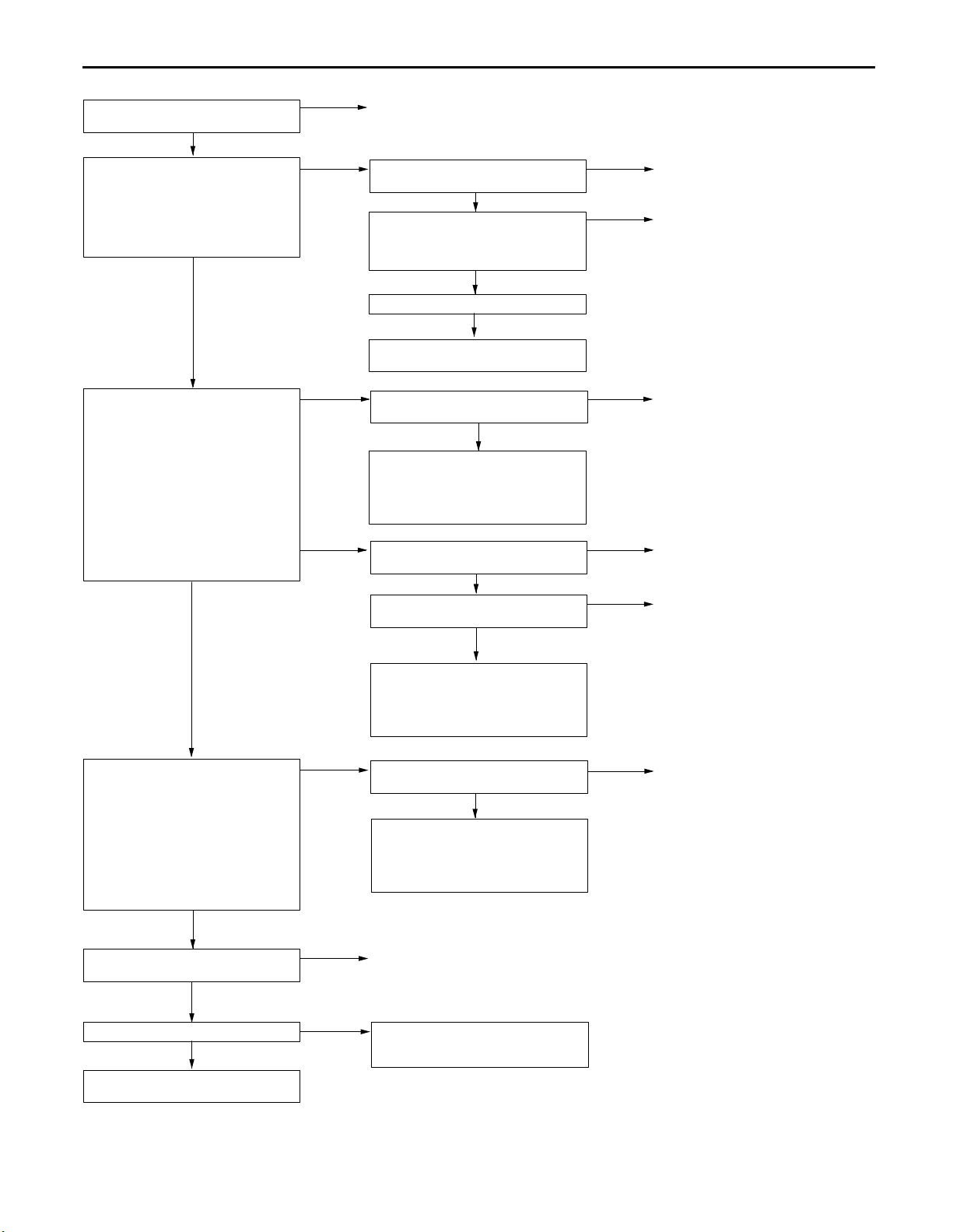
13A-30
GDI – Troubleshooting
Check the following connector:
D-22
OK
Measure at oxygen sensor (rear)
connector D-22.
Disconnect the connector and
measure at the harness side.
Resistance between terminal 2
and earth
OK: 2 Ω or less
OK
Measure at oxygen sensor (rear)
connector D-22.
Measure the voltage at the
oxygen sensor (rear) terminal.
Engine: 2,500 r/min (after
warming up)
(1) Voltage between terminal 2 and
earth
OK: 0.5 V or less
(2) Voltage between terminal 1 and
earth
OK: 0 V and 0.8 V alternate.
OK
NG
NG
(1) NG
(2) NG
Repair
Check the following connectors:
B-87 <M/T>, B-86 <A/T>
OK
Check the harness wire between
the oxygen sensor (rear) and the
engine-ECU <M/T> or
engine-A/T-ECU <A/T>.
OK
Check the trouble symptoms.
NG
Replace the engine-ECU <M/T> or
engine-A/T-ECU <A/T>.
Check the following connectors:
B-87 <M/T>, B-86 <A/T>
OK
Check the harness wire between
the oxygen sensor (rear) and the
engine-ECU <M/T> or
engine-A/T-ECU <A/T>, and repair if
necessary.
Check the oxygen sensor (rear).
(Refer to P.13A-128.)
OK
Check the following connector:
B-86
OK
NG
NG
NG
NG
NG
Repair
Repair
Repair
Replace
Repair
Measure at engine-ECU connector
B-86 <M/T> or engine-A/T-ECU
connector B-86 <A/T>.
Measure the voltage at the
engine-ECU terminal <M/T> or
engine-A/T-ECU terminal <A/T>.
Engine: 2,500 r/min (after
warming up)
Voltage between terminal 53
<M/T>, 73 <A/T> and earth
OK: 0 V and 0.8 V alternate.
OK
Check the following connectors:
B-86 , B-87 <M/T>, B-86 <A/T>
OK
Check the trouble symptoms.
NG
Replace the engine-ECU <M/T> or
engine-A/T-ECU <A/T>.
NG
NG
OK
Check the harness wire between
the oxygen sensor (rear) and the
engine-ECU <M/T> or
engine-A/T-ECU <A/T>, and repair if
necessary.
Check the following connector:
B-86
OK
Check the harness wire between
the oxygen sensor (rear) and the
engine-ECU <M/T> or
engine-A/T-ECU <A/T>, and repair if
necessary.
Repair
Transient malfunction
(Refer to GROUP 00 – Points to
Note for Intermittent Malfunctions.)
NG
Repair
 Loading...