

Mitsubishi PUH-P25_140(VY)GAA, PU-P35_140(VY)GAA Service Manual
SPLIT-TYPE, HEAT PUMP AIR CONDITIONERS
SPLIT -TYPE, AIR CONDITIONERS
SERVICE MANUAL
R407C
Outdoor unit
[model names]
PUH-P25VGAA
PUH-P35VGAA PU-P35VGAA
PUH-P35YGAA PU-P35YGAA
PUH-P50VGAA PU-P50VGAA
PUH-P50YGAA PU-P50YGAA
PUH-P60VGAA PU-P60VGAA
[Service Ref.]
Service Ref. is on page 2.
August 2005
No.OC336
• This manual describes only
service data of the outdoor
units.
PUH-P60YGAA PU-P60YGAA
PUH-P71VGAA PU-P71VGAA
PUH-P71YGAA PU-P71YGAA
PUH-P100VGAA PU-P100VGAA
PUH-P100YGAA PU-P100YGAA
PUH-P125YGAA PU-P125YGAA
PUH-P140YGAA PU-P140YGAA
CONTENTS
1. REFERENCE MANUAL··································3
2. SAFETY PRECAUTION ··································4
3. PART NAMES AND FUNCTIONS··················6
4. SPECIFICATIONS ···········································7
5. DATA ·····························································11
6. OUTLINES AND DIMENSIONS····················18
7. WIRING DIAGRAM·······································22
8. WIRING SPECIFICATIONS ··························24
9.
REFRIGERANT SYSTEM DIAGRAM
10. TROUBLESHOOTING··································30
11. FUNCTION SETTING ···································65
12. DISASSEMBLY PROCEDURE·····················71
13. PARTS LIST··················································75
··············28

[Service Ref.]
PUH-P25VGAA.UK
PUH-P35VGAA.UK PU-P35VGAA.UK
PUH-P35YGAA.UK PU-P35YGAA.UK
PUH-P50VGAA.UK PU-P50VGAA.UK
PUH-P50YGAA.UK PU-P50YGAA.UK
PUH-P60VGAA.UK PU-P60VGAA.UK
PUH-P60YGAA.UK PU-P60YGAA.UK
PUH-P71VGAA.UK PU-P71VGAA.UK
PUH-P71YGAA.UK PU-P71YGAA.UK
PUH-P100VGAA.UK PU-P100VGAA.UK
PUH-P100YGAA.UK PU-P100YGAA.UK
PUH-P125YGAA.UK PU-P125YGAA.UK
PUH-P140YGAA.UK PU-P140YGAA.UK
2
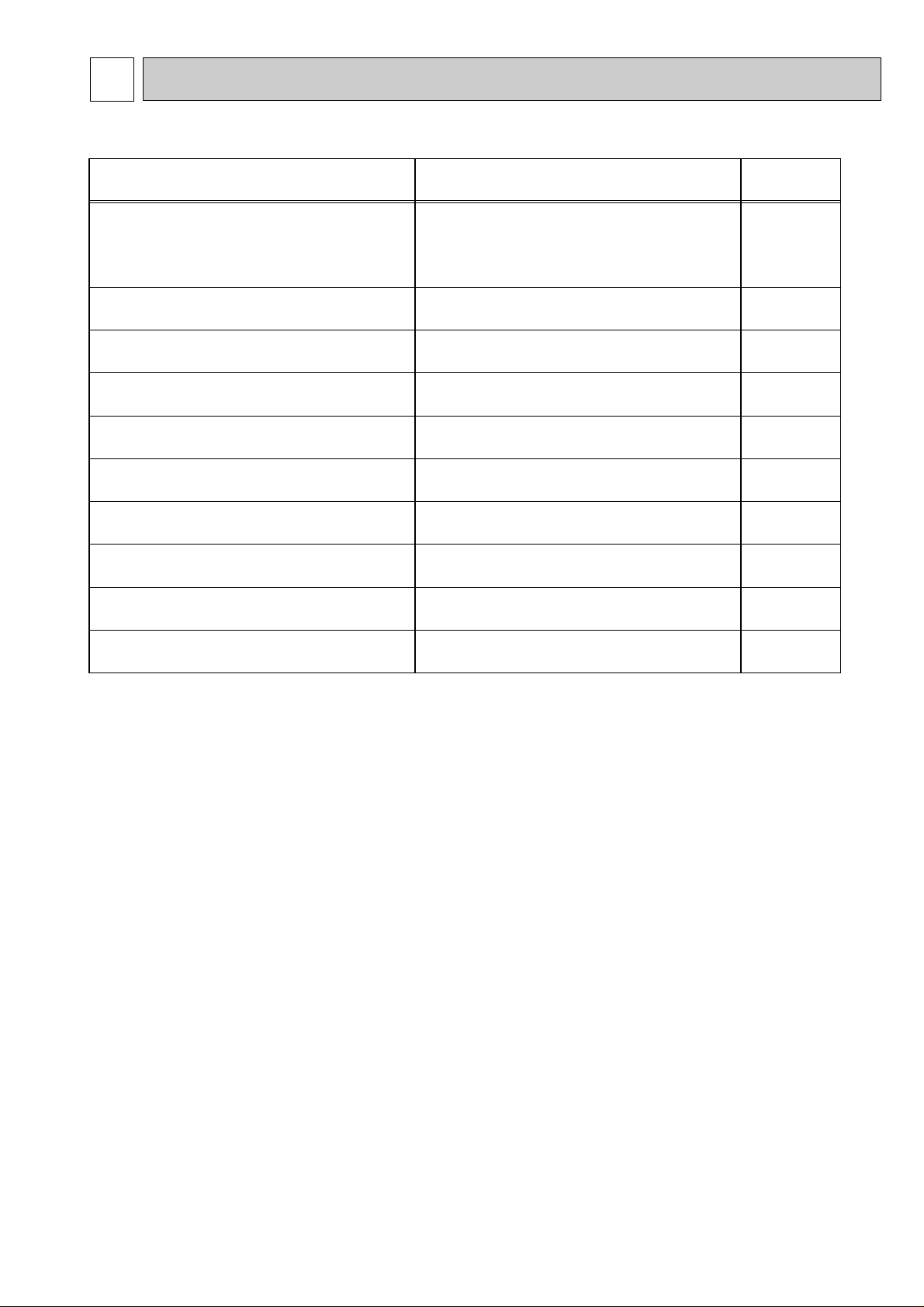
1-1. INDOOR UNIT'S SERVICE MANUAL
Model name Service Ref. Service
Manual No.
PLA-RP35/50/60/71AA PLA-RP35/50/60/71AA.UK OC335
PLA-RP100/125/140AA PLA-RP100/125/140AA.UK
PLH-P35/50/60/71AAH PLH-P35/50/60/71AAH.UK
PLH-P100/125/140AAH PLH-P100/125/140AAH.UK
PMH-P25/35/50BA PMH-P25/35/50BA OC333
PCA-RP50/60/71/100/125/140GA PCA-RP50/60/71/100/125/140GA OC328
PCH-P50/60/71/100/125/140GAH PCH-P50/60/71/100/125/140GAH
PCA-RP71/125HA PCA-RP71/125HA OC329
PKA-RP35/50GAL PKA-RP35/50GAL OC330
PKH-P35/50GALH PKH-P35/50GALH
PKA-RP60/71/100FAL PKA-RP60/71/100FAL OC331
PKH-P60/71/100FALH PKH-P60/71/100FALH
PSA-RP71/100/125/140GA PSA-RP71/100/125/140GA OC332
PSH-P71/100/125/140GAH PSH-P71/100/125/140GAH
PEAD-RP35/50/60/71EA PEAD-RP35/50/60/71EA.UK PEAD-RP100/125/140EA PEAD-RP100/125/140EA.UK
PEHD-P35/50/60/71EAH PEHD-P35/50/60/71EAH.UK PEHD-P100/125/140EAH PEHD-P100/125/140EAH.UK
PEAD-RP60/71/100GA PEAD-RP60/71/100GA.UK -
1-2. TECHNICAL DATA BOOK
1
REFERENCE MANUAL
Manual No.OCS02
3
2
Do not use the existing refrigerant piping.
The old refrigerant and lubricant in the existing piping
contains a large amount of chlorine which may cause the
lubricant deterioration of the new unit.
Use “low residual oil piping”
If there is a large amount of residual oil (hydraulic oil, etc.)
inside the piping and joints, deterioration of the lubricant
will result.
Use ESTER , ETHER or HAB as the lubricant to
coat flares and flange connection parts.
If large amount of mineral oil enter, that can cause
deterioration of refrigerant oil etc.
Use liquid refrigerant to charge the system.
If gas refrigerant is used to seal the system, the composition
of the refrigerant in the cylinder will change and performance
may drop.
Do not use a refrigerant other than R407C.
If another refrigerant (R22, etc.) is used, the chlorine in the
refrigerant may cause the lubricant deterioration.
Use a vacuum pump with a reverse flow check valve.
The vacuum pump oil may flow back into the refrigerant
cycle and cause the lubricant deterioration.
Store the piping to be used during installation
indoors with keep both ends sealed until just
before brazing.
(Store elbows and other joints in a plastic bag.)
If dust, dirt, or water enters the refrigerant cycle,
deterioration of the oil and compressor trouble may result.
Ventilate the room if refrigerant leaks during
operation. If refrigerant comes into contact with
a flame, poisonous gases will be released.
Gravimeter
Unit
SAFETY PRECAUTION
CAUTIONS RELATED TO NEW REFRIGERANT
Cautions for units utilising refrigerant R407C
[1] Cautions for service
·After recovering the all refrigerant in the unit, proceed to working.
·Do not release refrigerant in the air.
·After completing the repair service, recharge the cycle with the specified amount of
liquid refrigerant.
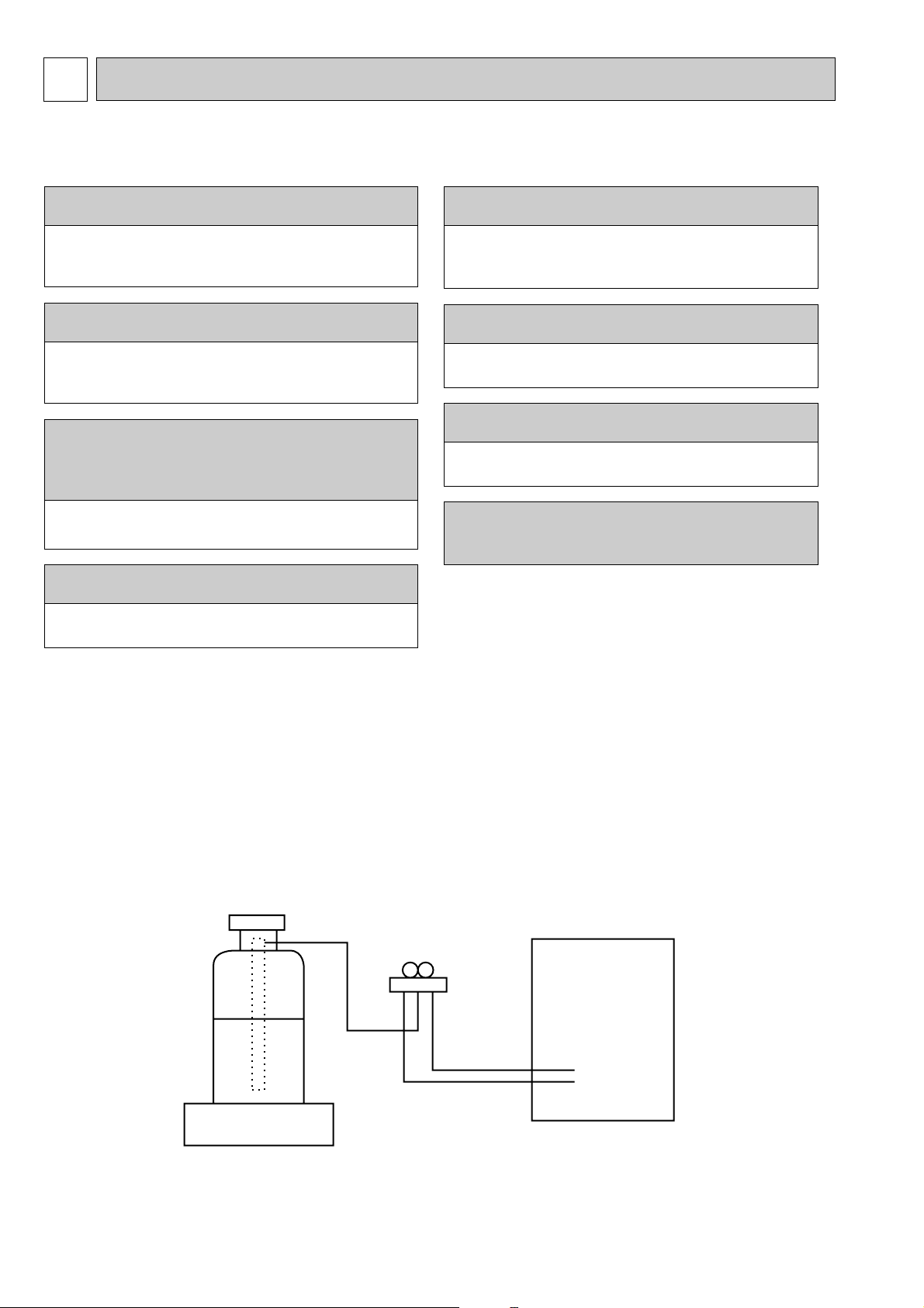
[2] Refrigerant recharging
(1) Refrigerant recharging process
1Direct charging from the cylinder.
·R407C cylinder are available on the market has a syphon pipe.
·Leave the syphon pipe cylinder standing and recharge it.
(By liquid refrigerant)
(2) Recharge in refrigerant leakage case
·After recovering the all refrigerant in the unit, proceed to working.
·Do not release the refrigerant in the air.
·After completing the repair service, recharge the cycle with the specified amount of
liquid refrigerant.
4
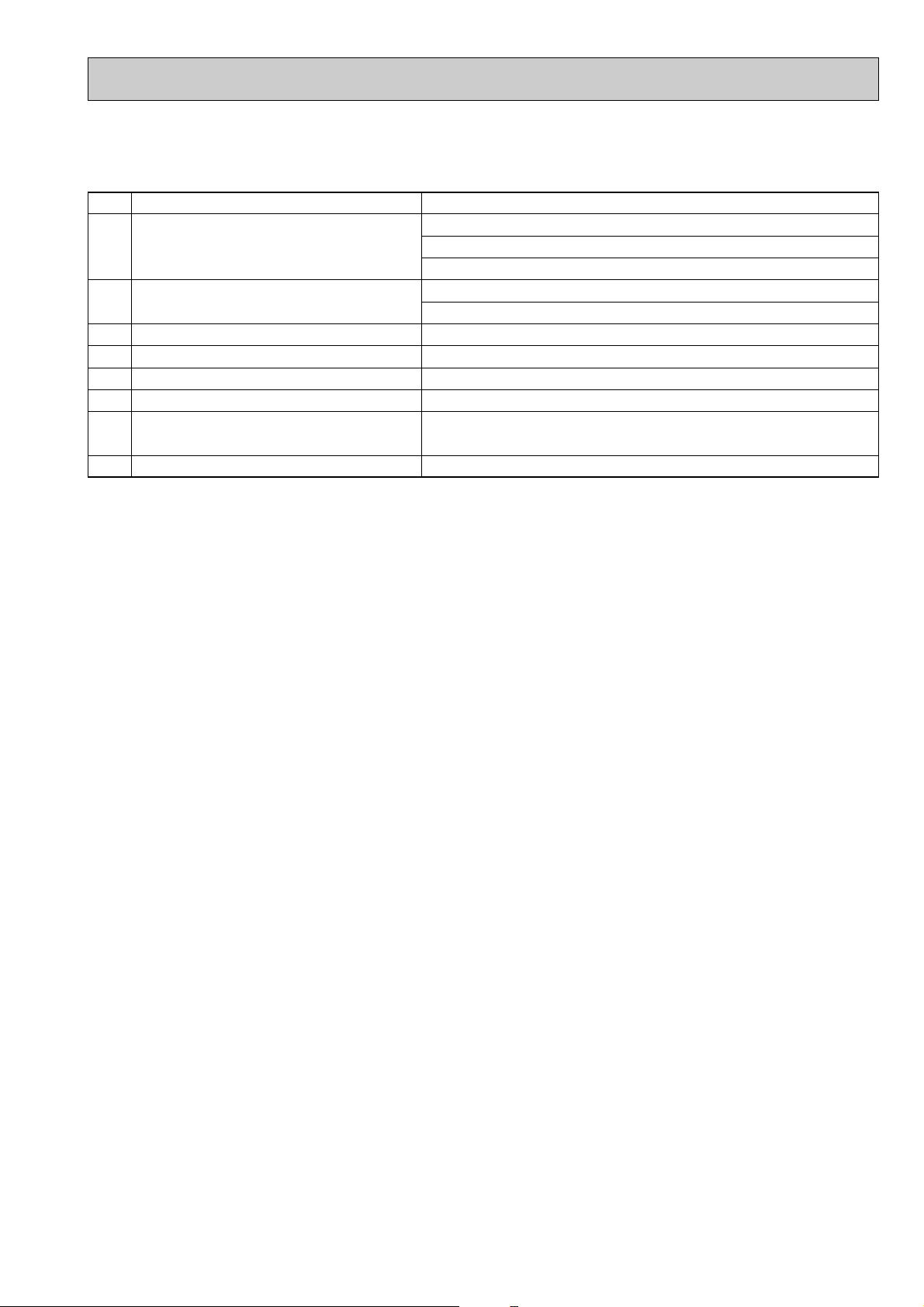
[3] Service tools
Use the below service tools as exclusive tools for R407C refrigerant.
No. Tool name Specifications
1 Gauge manifold ·Only for R407C.
·Use the existing fitting SPECIFICATIONS. (UNF7/16)
·Use high-tension side pressure of 3.43MPa·G or over.
2 Charge hose ·Only for R407C.
·Use pressure performance of 5.10MPa·G or over.
3 Electronic scale
4 Gas leak detector ·Use the detector for R134a or R407C.
5 Adapter for reverse flow check. ·Attach on vacuum pump.
6 Refrigerant charge base.
7 Refrigerant cylinder. ·For R407C ·Top of cylinder (Brown)
·Cylinder with syphon
8 Refrigerant recovery equipment.
5
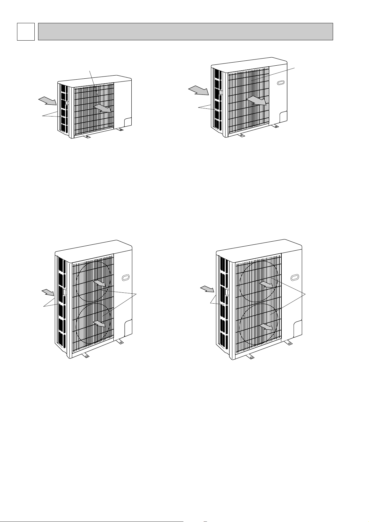
3 PART NAMES AND FUNCTIONS
Air intake
Air outlet
(Expels warm air during cooling)
Air intake
Air outlet
Air intake
Air outlet
Air intake
Air outlet
PUH-P25VGAA.UK
PUH-P35VGAA.UK
PUH-P35YGAA.UK
PU-P35VGAA.UK
PU-P35YGAA.UK
PUH-P50VGAA.UK PUH-P50YGAA.UK
PUH-P60VGAA.UK PUH-P60YGAA.UK
PUH-P71VGAA.UK PUH-P71YGAA.UK
PU-P50VGAA.UK PU-P50YGAA.UK
PU-P60VGAA.UK PU-P60YGAA.UK
PU-P71VGAA.UK PU-P71YGAA.UK
PUH-P100VGAA.UK
PUH-P100YGAA.UK
PU-P100VGAA.UK
PU-P100YGAA.UK
CHARGELESS SYSTEM
PRE-CHARGED REFRIGERANT IS SUPPLIED FOR PIPING LENGTH AT SHIPMENT.
PU/PUH-P25, P35, P50, P60 : max 20m
PU/PUH-P71, P100, P125, P140 : max 30m
The refrigerant circuit with LEV(Linear Expansion Valve) and a large accumulator always control the optimal refrigerant
level regardless of the length (20/30m max. and 5m min.) of piping. The additional refrigerant charging work during
installation often causes problems. Heretofore it is completely eliminated. This unique system improves the quality
and reliability of the work done.It also helps to speed up the installation time.
PUH-P125YGAA.UK
PUH-P140YGAA.UK
PU-P125YGAA.UK
PU-P140YGAA.UK
6
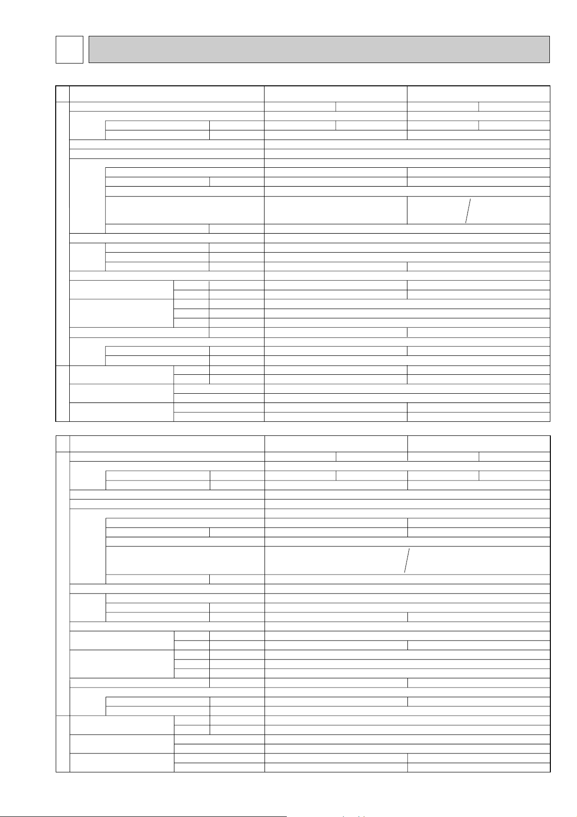
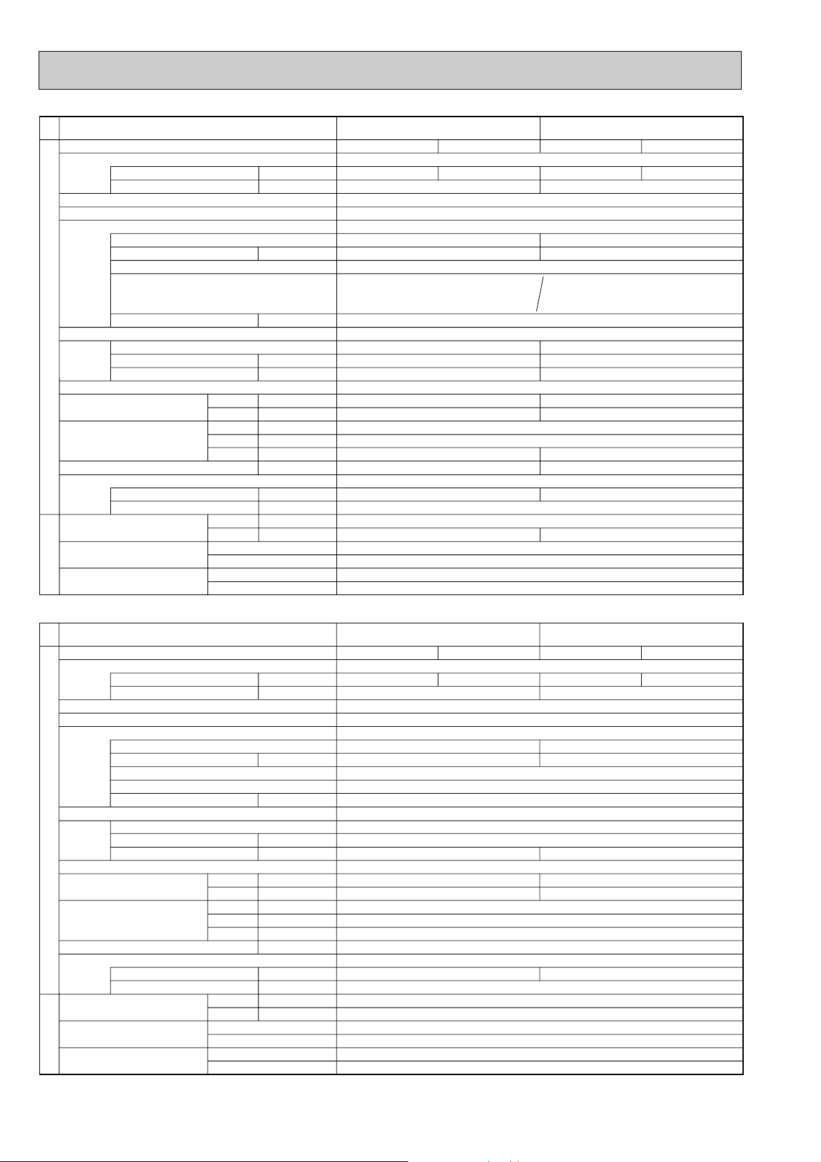
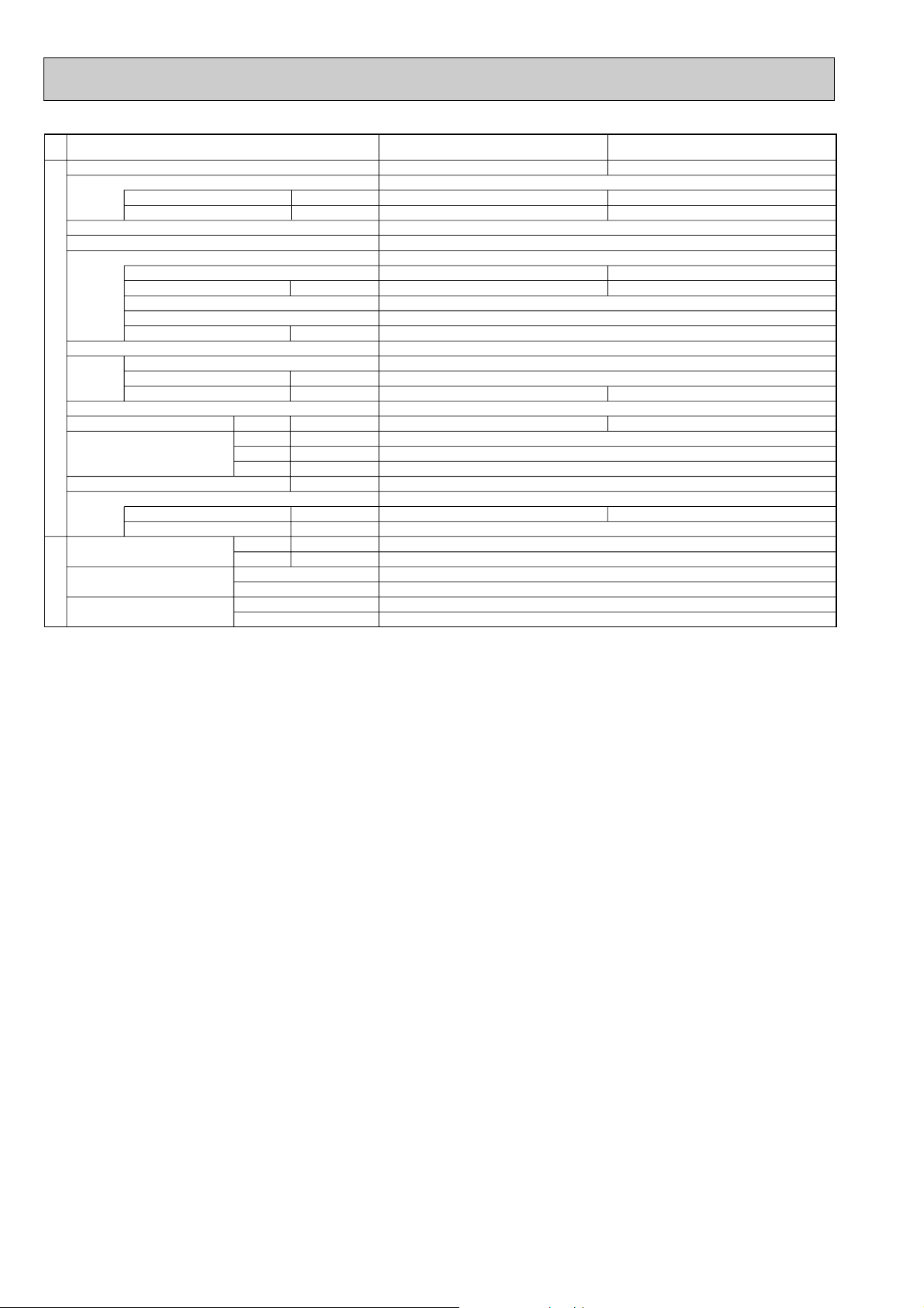
4 SPECIFICATIONS
A
A
kW
W
kW
K
/min(CFM
)
dB
dB
mm(in.)
mm(in.)
mm(in.)
kg(lbs)
kg(lbs)
L
mm(in.)
mm(in.)
Mode
Power supply (phase, cycle, voltage)
Running current
Max current
External finish
Refrigerant control
Compressor
Model
Motor output
Starter type
Protection devices
Crankcase heater
Heat exchanger
Fan Fan(drive) o No.
Fan motor output
Airflow
Defrost method
Noise level
Dimensions
Weight
Refrigerant
Charge
Oil (Model)
Pipe size O.D.
Connection method
Between the indoor &
outdoor unit
OUTDOOR UNIT
REFRIGERANT PIPING
Cooling
Heating
W
D
H
Liquid
Gas
Indoor side
Outdoor side
Height difference
Piping length
Service Ref.
PUH-P25VAA.UK
PUH-P35VGAA / YGAA.UK
Cooling
5.32
Single,50Hz,230V
7.23
RE189VHSMT
0.9
45(1,590)
46
48
50(110)
1.7(3.8)
6.35(1/4)
12.7(1/2)
Max. 30m
Max. 30m
Munsell 5Y 7/1
Linear Expansion Valve
Hermetic
Line start
30
Plate fin coil
Propeller (direct) o 1
0.07
Reverse cycle
900(35-7/16)
330+20(13+3/4)
650(25-5/8)
R407C
0.57(Ester)MEL56
Flared
Flared
Heating
4.89
Cooling
7.61 / 2.54
Single,50Hz,230V / 3-ph,50Hz,400V
10.67/5.4
RE277VHSMT/RE277YFKM
1.3
45(1,590)
47
49
54(119)
2.5(5.5)
9.52(3/8)
15.88(5/8)
Max. 40m
Max. 40m
Heating
7.85 / 2.62
Internal thermostat
HP switch
Discharge thermo
Thermal relay
HP switch
Discharge thermo
Internal thermostat
HP switch
Discharge thermo
A
A
kW
W
kW
K
/min(CFM
)
dB
dB
mm(in.)
mm(in.)
mm(in.)
kg(lbs)
kg(lbs)
L
mm(in.)
mm(in.)
Mode
Power supply (phase, cycle, voltage)
Running current
Max current
External finish
Refrigerant control
Compressor
Model
Motor output
Starter type
Protection devices
Crankcase heater
Heat exchanger
Fan Fan(drive) o No.
Fan motor output
Airflow
Defrost method
Noise level
Dimensions
Weight
Refrigerant
Charge
Oil (Model)
Pipe size O.D.
Connection method
Between the indoor &
outdoor unit
OUTDOOR UNIT
REFRIGERANT PIPING
Cooling
Heating
W
D
H
Liquid
Gas
Indoor side
Outdoor side
Height difference
Piping length
Service Ref.
PUH-P50VGAA / YGAA.UK
PUH-P60VGAA / YGAA.UK
Cooling
10.97 / 3.98
15.35 /7.0
NE36VMJMT / NE36YEKMT
1.6
55(1,940)
49
74(163)
2.6(5.7)
Max. 40m
Max. 40m
Single, 50Hz, 230V / 3-ph, 50Hz,400V(4wires)
Munsell 5Y 7/1
Linear Expansion Valve
Hermetic
Line start
38
Plate fin coil
Propeller (direct) o 1
0.07
Reverse cycle
48
900(35-7/16)
330+20(13+3/4)
855(33-5/8)
R407C
1.2 (Ester)MEL56
9.52(3/8)
15.88(5/8)
Flared
Flared
Heating
11.30 / 3.95
Cooling
13.27 / 4.43
18.03 / 7.7
NE41VMJMT / NE41YEKMT
1.9
50(1,770)
50
79(174)
3.1(6.8)
Max. 50m
Max. 50m
Heating
12.84/ 4.29
Internal thermostat
HP switch
Discharge thermo
Thermal relay
HP switch
Discharge thermo
4-1. HEAT PUMP
7
Service Ref.
Mode
Power supply (phase, cycle, voltage)
External finish
Refrigerant control
Compressor
Heat exchanger
OUTDOOR UNIT
Fan Fan(drive) o No.
Defrost method
Noise level
Dimensions
Weight
Refrigerant
Pipe size O.D.
Connection method
Between the indoor &
outdoor unit
REFRIGERANT PIPING
Running current
Max current
Model
Motor output
Starter type
Protection devices
Crankcase heater
Fan motor output
Airflow
Charge
Oil (Model)
Indoor side
Outdoor side
Height difference
Piping length
Cooling
Heating
W
D
H
Liquid
Gas
kW
kW
K
/min(CFM
dB
dB
mm(in.)
mm(in.)
mm(in.)
kg(lbs)
kg(lbs)
mm(in.)
mm(in.)
PUH-P71VGAA / YGAA.UK
A
A
W
)
L
Cooling
15.66 / 5.23
NE52VNJMT / NE52YDKMT
Single, 50Hz, 230V / 3-ph, 50Hz, 400V(4wires)
22.66 / 10.8
Propeller (direct) o 1
0.07
50(1,770)
855(33-5/8)
79(174)
3.3(7.3)
15.88(5/8)
Heating
16.67 / 5.56
Munsell 5Y 7/1
Linear Expansion Valve
Hermetic
2.5
Line start
Internal thermostat
HP switch
Discharge thermo
Plate fin coil
Reverse cycle
49
51
900(35-7/16)
330+20(13+3/4)
R407C
1.3 (Ester)MEL56
9.52(3/8)
Flared
Flared
Max. 50m
Max. 50m
PUH-P100VGAA / YGAA.UK
Cooling
16.43/ 5.48
23.57 / 10.8
NE56VNJMT / NE56YDKMT
Thermal relay
HP switch
Discharge thermo
38
Propeller (direct) o 2
0.07+0.07
85(3,000)
1,260(49-5/8)
97(214)
4.0(8.8)
19.05(3/4)
Heating
17.34 / 5.79
2.7
51
53
Service Ref.
Mode
Power supply (phase, cycle, voltage)
External finish
Refrigerant control
Compressor
Heat exchanger
OUTDOOR UNIT
Fan Fan(drive) o No.
Defrost method
Noise level
Dimensions
Weight
Refrigerant
Pipe size O.D.
Connection method
Between the indoor &
outdoor unit
REFRIGERANT PIPING
Running current
Max current
Model
Motor output
Starter type
Protection devices
Crankcase heater
Fan motor output
Airflow
Charge
Oil (Model)
Indoor side
Outdoor side
Height difference
Piping length
Cooling
Heating
W
D
H
Liquid
Gas
kW
kW
/min(CFM
K
dB(A)
dB(A)
mm(in.)
mm(in.)
mm(in.)
kg(lbs)
kg(lbs)
mm(in.)
mm(in.)
PUH-P125YGAA.UK
Cooling
A
A
W
)
L
7.52
18.0
BE82YADMT
95(3,360)
4.6(10.1)
Heating
3-ph, 50Hz, 400V(4wires)
8.06
Munsell 5Y 7/1
Linear Expansion Valve
Hermetic
3.5
Line start
Thermal relay, HP switch, Discharge thermo
38
Plate fin coil
Propeller (direct) o 2
0.07 +0.07
Reverse cycle
55
56
1,050(41-5/16)
330+20(13+3/4)
1,260(49-5/8)
125(276)
R407C
1.7 (Ester) MEL56
9.52(3/8)
19.05(3/4)
Flared
Flared
Max. 50m
Max. 50m
PUH-P140YGAA.UK
Cooling
8.92
20.4
BE96YADMT
4.2
100(3,530)
57
58
4.9(10.8)
Heating
9.45
8
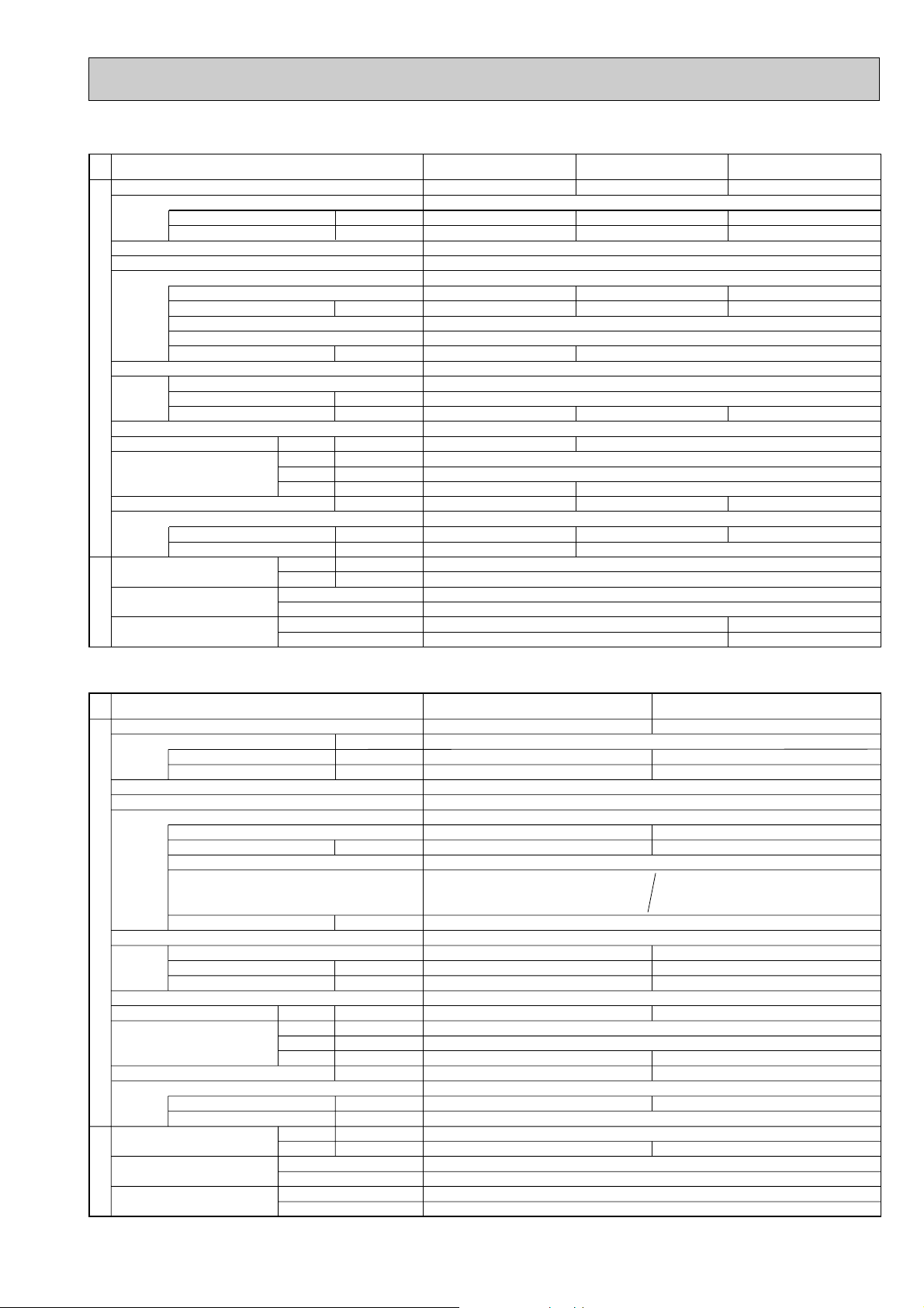
4-2. COOLING ONLY TYPE
A
A
kW
W
kW
K
/min(CFM
)
dB
mm(in.)
mm(in.)
mm(in.)
kg(lbs)
kg(lbs)
L
mm(in.)
mm(in.)
Mode
Power supply (phase, cycle, voltage)
Running current
Max. current
External finish
Refrigerant control
Compressor
Model
Motor output
Starter type
Protection devices
Crankcase heater
Heat exchanger
Fan Fan(drive) o No.
Fan motor output
Airflow
Defrost method
Noise level
Dimensions
Weight
Refrigerant
Charge
Oil (Model)
Pipe size O.D.
Connection method
Between the indoor &
outdoor unit
OUTDOOR UNIT
REFRIGERANT PIPING
Cooling
W
D
H
Liquid
Gas
Indoor side
Outdoor side
Height difference
Piping length
Service Ref. PU-P71VGAA / YGAA.UK PU-P100VGAA / YGAA.UK
Cooling
15.66 / 5.23
22.66 / 10.8
NE52VNJMT / NE52YDKMT
2.5
Propeller (direct) o 1
0.07
50(1,770)
49
855(33-5/8)
79(174)
3.3(7.3)
15.88(5/8)
Single, 50Hz, 230V / 3-ph, 50Hz, 400V(4wires)
Munsell 5Y 7/1
Linear Expansion Valve
Hermetic
Line start
38
Plate fin coil
—
900(35-7/16)
330+20(13+3/4)
R407C
1.3 (Ester)MEL56
9.52(3/8)
Flared
Flared
Max. 50m
Max. 50m
Cooling
16.43/ 5.48
23.57 / 10.8
NE56VNJMT / NE56YDKMT
2.7
Propeller (direct) o 2
0.07+0.07
85(3,000)
51
1,260(49-5/8)
97(214)
4.0(8.8)
19.05(3/4)
Internal thermostat
HP switch
Discharge thermo
Thermal relay
HP switch
Discharge thermo
Service Ref.
Mode
Power supply (phase, cycle, voltage)
External finish
Refrigerant control
Compressor
OUTDOOR UNIT
Heat exchanger
Fan Fan(drive) o No.
Defrost method
Noise level
Dimensions
Weight
Refrigerant
Pipe size O.D.
Connection method
Between the indoor &
REFRIGERANT PIPING
outdoor unit
Running current
Max. current
Model
Motor output
Starter type
Protection devices
Crankcase heater
Fan motor output
Airflow
Charge
Oil (Model)
/min(CFM
K
Cooling
W
D
H
Liquid
Gas
Indoor side
Outdoor side
Height difference
Piping length
mm(in.)
mm(in.)
mm(in.)
kg(lbs)
kg(lbs)
mm(in.)
mm(in.)
A
A
kW
W
kW
dB
L
PU-P35VGAA / YGAA.UK
Cooling
7.61 / 2.54
10.67 / 5.4
RE277VHSMT/RE277YFKM
Internal thermostat, HP switch, Discharge thermo / Thermal relay,Discharge thermo,HP switch
)
45(1,590)
650(25-5/8)
0.57 (Ester)MEL56
Single, 50Hz, 230V / 3-ph, 50Hz, 400V(4wires)
1.3
30
47
54(119)
2.5(5.5)
PU-P50VGAA / YGAA.UK
Cooling
10.97 / 3.98
15.35 / 7.0
Munsell 5Y 7/1
Linear Expansion Valve
Hermetic
NE36VMJMT/NE36YEKMT
1.6
Line start
Plate fin coil
Propeller (direct) o 1
0.07
55(1,940)
—
900(35-7/16)
330+20(13+3/4)
74(163)
R407C
2.6(5.7)
9.52(3/8)
15.88(5/8)
Flared
Flared
Max. 40m
Max. 40m
PU-P60VGAA / YGAA.UK
Cooling
13.27 / 4.43
18.03 / 7.7
NE41VMJMT/NE41YEKMT
1.9
38
50(1,770)
48
855(33-5/8)
79(174)
3.1(6.8)
1.2 (Ester)MEL56
Max. 50m
Max. 50m
9
Service Ref.
Mode
Power supply (phase, cycle, voltage)
External finish
Refrigerant control
Compressor
OUTDOOR UNIT
Heat exchanger
Fan Fan(drive) o No.
Defrost method
Noise level
Dimensions
Weight
Refrigerant
Pipe size O.D.
Connection method
Between the indoor &
outdoor unit
REFRIGERANT PIPING
Running current
Max. current
Model
Motor output
Starter type
Protection devices
Crankcase heater
Fan motor output
Airflow
Cooling
Charge
Oil (Model)
Indoor side
Outdoor side
Height difference
Piping length
W
D
H
Liquid
Gas
kW
kW
/min(CFM
K
dB
mm(in.)
mm(in.)
mm(in.)
kg(lbs)
kg(lbs)
mm(in.)
mm(in.)
PU-P125YGAA.UK PU-P140YGAA.UK
Cooling
A
A
W
)
L
7.52
18.0
BE82YADMT
3.5
Thermal relay, HP switch, Discharge thermo
95(3,360)
55
4.6(10.1)
3-ph, 50Hz,400V(4wires)
Munsell 5Y 7/1
Linear Expansion Valve
Hermetic
Line start
38
Plate fin coil
Propeller (direct) o 2
0.07+0.07
—
1,050(41-5/16)
330+20(13+3/4)
1,260(49-5/8)
125(276)
R407C
1.7 (Ester) MEL56
9.52(3/8)
19.05(3/4)
Flared
Flared
Max. 50m
Max. 50m
Cooling
8.92
20.4
BE96YADMT
4.2
100(3,530)
57
4.9(10.8)
10
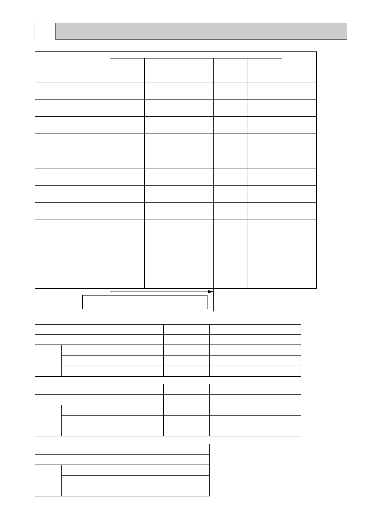
5 DATA
Piping length (one way)
10m 20m 30m
40m
50m
Factory
charged
1.6
2.4
2.4
2.5
2.5
2.9
2.9
2.9
2.9
3.4
3.4
4.0
4.3
1.7
2.5
2.5
2.6
2.6
3.1
3.1
3.1
3.1
3.7
3.7
4.3
4.6
1.8
2.6
2.6
3.1
3.1
3.3
3.3
3.3
3.3
4.0
4.0
4.6
4.9
—
3.0
3.0
3.7
3.7
3.9
3.9
3.9
3.9
4.7
4.7
5.3
5.6
—
—
—
—
—
4.5
4.5
4.5
4.5
5.4
5.4
6.0
6.3
1.7
2.5
2.5
2.6
2.6
3.1
3.1
3.3
3.3
4.0
4.0
4.6
4.9
Service Ref.
PUH-P140YGAA.UK
PU-P140YGAA.UK
PUH-P125YGAA.UK
PU-P125YGAA.UK
PUH-P100VGAA.UK
PU-P100VGAA.UK
PUH-P100YGAA.UK
PU-P100YGAA.UK
PUH-P71YGAA.UK
PU-P71YGAA.UK
PUH-P71VGAA.UK
PU-P71VGAA.UK
PUH-P60YGAA.UK
PU-P60YGAA.UK
PUH-P60VGAA.UK
PU-P60VGAA.UK
PUH-P50YGAA.UK
PU-P50YGAA.UK
PUH-P50VGAA.UK
PU-P50VGAA.UK
PUH-P35YGAA.UK
PU-P35YGAA.UK
PUH-P35VGAA.UK
PU-P35VGAA.UK
PUH-P25VGAA.UK
Compressor model
Winding
Resistance
( " )
U-V
(R-C)
U-W
(S-C)
W-V
U-V
(R-C)
U-W
(S-C)
W-V
RE277VHSMT RE277YFKM
Unit
NE36VMJMT
1.80
3.00
—
10.8
10.8
10.8
5.01
5.01
5.01
NE36YEKMT
0.89
2.03
—
Unit
Compressor model
Winding
Resistance
( " )
(at 20°C)
BE96YADMTBE82YADMT
2.123
2.123
2.123
NE52VNJMT
0.64
1.67
—
3.59
3.59
3.59
1.963
1.963
1.963
NE56YDKMT
3.32
3.32
3.32
PUH-P35VGAA.UK
PU-P35VGAA.UK
PUH-P35YGAA.UK
PU-P35YGAA.UK
PUH-P50VGAA.UK
PU-P50VGAA.UK
PUH-P50YGAA.UK
PU-P50YGAA.UK
PUH-P25VGAA.UK
PUH-P60YGAA.UK
PU-P60YGAA.UK
PUH-P60VGAA.UK
PU-P60VGAA.UK
PUH-P71VGAA.UK
PU-P71VGAA.UK
PUH-P100VGAA.UK
PU-P100VGAA.UK
PUH-P71YGAA.UK
PU-P71YGAA.UK
PUH-P125YGAA.UK
PU-P125YGAA.UK
PUH-P100YGAA.UK
PU-P100YGAA.UK
U-V
(R-C)
U-W
(S-C)
W-V
Unit
Compressor model
Winding
Resistance
( " )
NE41VMJMT
NE41YEKMT
5.00
5.00
5.00
NE56VNJMT
0.62
1.59
—
RE189VHSMT
2.79
3.36
—
0.87
2.22
—
NE52YDKMT
PUH-P140YGAA.UK
PU-P140YGAA.UK
5-1. REFILLING REFRIGERANT CHARGE (R407C : kg)
5-2. COMPRESSOR TECHNICAL DATA
PRE- CHARGED REFRIGERANT IS SUPPLIED
FOR PIPING LENGTH AT SHIPMENT.
11
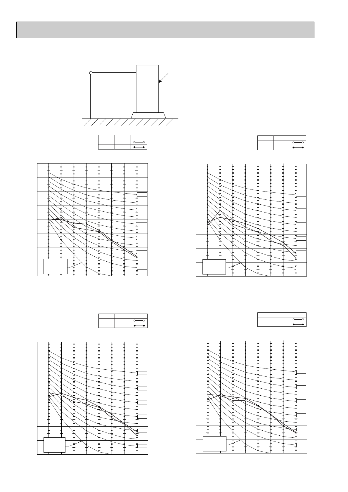
5-3. NOISE CRITERION CURVES
1m
1m
MICROPHONE
UNIT
GROUND
SPL(dB)48LINE
PUH-P25VGAA.UK
90
MODE
COOLING
HEATING
SPL(dB)49LINE
46
PUH-P35VGAA.UK
PUH-P35YGAA.UK
PU-P35VGAA.UK
MODE
COOLING
HEATING
47
PU-P35YGAA.UK
90
80
70
60
50
40
30
APPROXIMATE
20
THRESHOLD OF
HEARING FOR
CONTINUOUS
OCTAVE BAND SOUND PRESSURE LEVEL, dB (0 dB = 0.0002 µbar)
PUH-P50VGAA
NOISE
10
63 125 250 500 1000 2000 4000 8000
BAND CENTER FREQUENCIES, Hz
.UK
PUH-P50YGAA.UK
PU-P50VGAA.UK
PU-P50YGAA.UK
90
MODE
COOLING
HEATING
NC-70
NC-60
NC-50
NC-40
NC-30
NC-20
SPL(dB) LINE
48
49
80
70
60
50
40
30
APPROXIMATE
20
THRESHOLD OF
HEARING FOR
CONTINUOUS
OCTAVE BAND SOUND PRESSURE LEVEL, dB (0 dB = 0.0002 µbar)
NOISE
10
63 125 250 500 1000 2000 4000 8000
BAND CENTER FREQUENCIES, Hz
PUH-P60VGAA.UK
PUH-P60YGAA.UK
PU-P60VGAA.UK
PU-P60YGAA.UK
90
MODE
COOLING
HEATING
NC-70
NC-60
NC-50
NC-40
NC-30
NC-20
SPL(dB) LINE
48
50
80
70
60
50
40
30
APPROXIMATE
20
THRESHOLD OF
HEARING FOR
CONTINUOUS
NOISE
OCTAVE BAND SOUND PRESSURE LEVEL, dB (0 dB = 0.0002 µbar)
10
63 125 250 500 1000 2000 4000 8000
BAND CENTER FREQUENCIES, Hz
NC-70
NC-60
NC-50
NC-40
NC-30
NC-20
12
OCTAVE BAND SOUND PRESSURE LEVEL, dB (0 dB = 0.0002 µbar)
80
70
60
50
40
30
APPROXIMATE
20
THRESHOLD OF
HEARING FOR
CONTINUOUS
NOISE
10
63 125 250 500 1000 2000 4000 8000
BAND CENTER FREQUENCIES, Hz
NC-70
NC-60
NC-50
NC-40
NC-30
NC-20
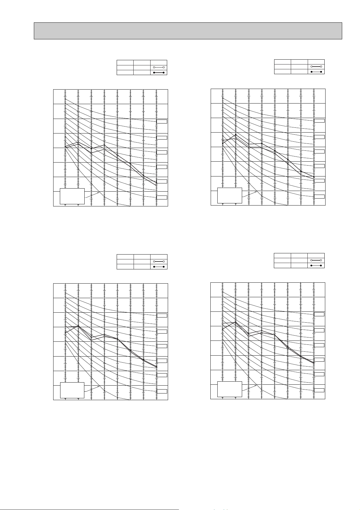
PUH-P71VGAA.UK
PUH-P71YGAA.UK
PU-P71VGAA.UK
PU-P71YGAA.UK
90
MODE
COOLING
HEATING
SPL(dB) LINE
49
51
PUH-P100VGAA.UK
PUH-P100YGAA.UK
PU-P100VGAA.UK
PU-P100YGAA.UK
90
MODE
COOLING
HEATING
SPL(dB)
51
53
LINE
80
70
60
50
40
30
APPROXIMATE
20
THRESHOLD OF
HEARING FOR
CONTINUOUS
NOISE
10
OCTAVE BAND SOUND PRESSURE LEVEL, dB (0 dB = 0.0002 µbar)
63 125 250 500 1000 2000 4000 8000
BAND CENTER FREQUENCIES, Hz
PUH-P125YGAA.UK
PU-P125YGAA.UK
MODE
COOLING
HEATING
NC-70
NC-60
NC-50
NC-40
NC-30
NC-20
SPL(dB) LINE
55
56
80
70
60
50
40
30
APPROXIMATE
20
THRESHOLD OF
HEARING FOR
CONTINUOUS
OCTAVE BAND SOUND PRESSURE LEVEL, dB (0 dB = 0.0002 µbar)
NOISE
10
63 125 250 500 1000 2000 4000 8000
BAND CENTER FREQUENCIES, Hz
PUH-P140YGAA.UK
PU-P140YGAA.UK
MODE
COOLING
HEATING
NC-70
NC-60
NC-50
NC-40
NC-30
NC-20
SPL(dB) LINE
57
58
OCTAVE BAND SOUND PRESSURE LEVEL, dB (0 dB = 0.0002 µbar)
90
80
70
60
50
40
30
APPROXIMATE
20
THRESHOLD OF
HEARING FOR
CONTINUOUS
NOISE
10
63 125 250 500 1000 2000 4000 8000
BAND CENTER FREQUENCIES, Hz
NC-70
NC-60
NC-50
NC-40
NC-30
NC-20
OCTAVE BAND SOUND PRESSURE LEVEL, dB (0 dB = 0.0002 µbar)
90
80
70
60
50
40
30
APPROXIMATE
20
THRESHOLD OF
HEARING FOR
CONTINUOUS
NOISE
10
63 125 250 500 1000 2000 4000 8000
BAND CENTER FREQUENCIES, Hz
NC-70
NC-60
NC-50
NC-40
NC-30
NC-20
13
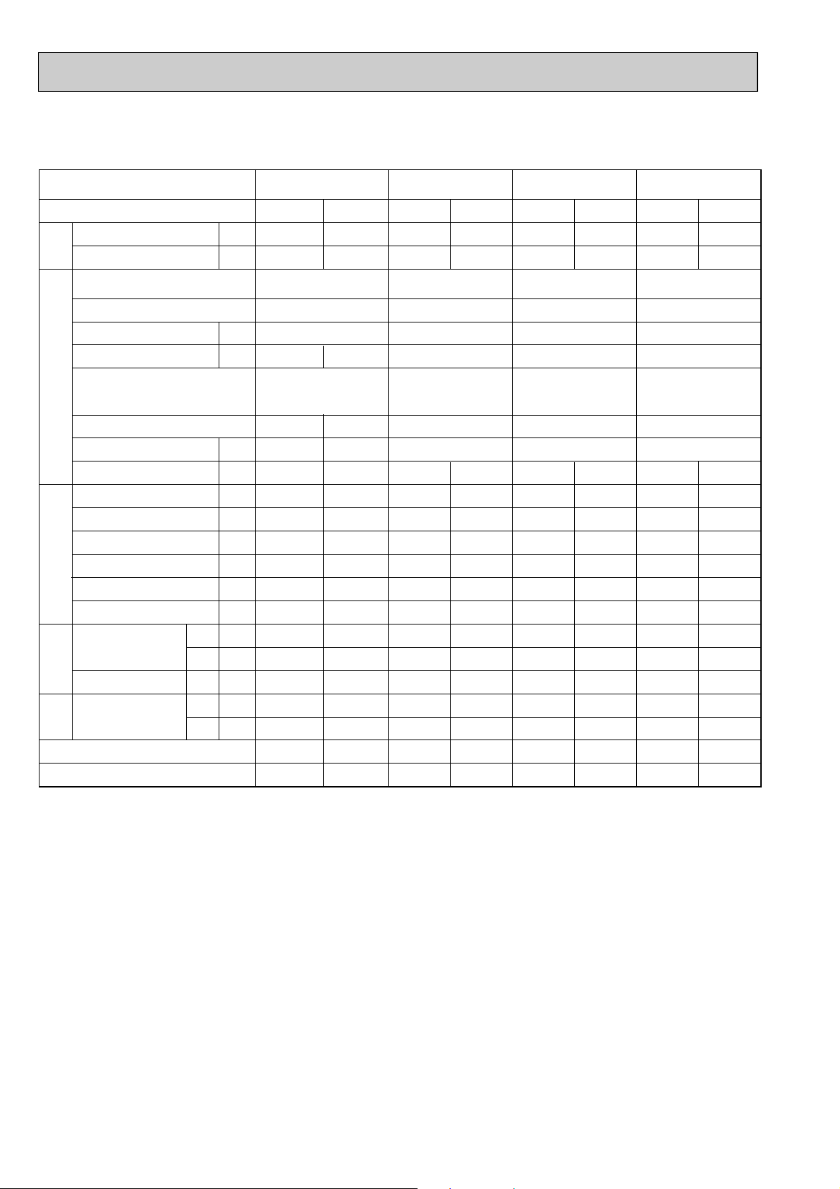
5-4. STANDARD OPERATION DATA
Heat pump type
Representative matching
Mode
Capacity
TotalElectrical circuitRefrigerant circuitIndoor side
Input
Indoor unit
Phase , Hz
Volts
Amperes
Outdoor unit
Phase , Hz
Volts
Amperes
Discharge pressure
Suction pressure
Discharge temperature
Condensing temperature
Suction temperature
Ref. pipe length
Intake air temperature
Discharge air temperature
Intake air temperature
side
Outdoor
SHF
BF
D.B.
W.B.
D.B.
D.B.
W.B.
W
kW
V
A
V
A
MPa
MPa
°C
°C
°C
m
°C
°C
°C
°C
°C
PMH-P25BA
Cooling
3,100
1.14
PMH-P25BA
0.19
PUH-P25VGAA.UK
1, 50
230
5.13
2.01
0.55
71
48
8.0
5
27
19
13.3
35
24
0.77
0.09
Heating
3,350
1.05
1, 50
230
0.19
1, 50
230
4.72
1.85
0.44
70
44
4.0
5
20
15
41.5
7
6
—
—
PLA-RP35AA
Cooling
4,500
1.72
PLA-RP35AA PLA-RP50AA PLA-RP60AA
PUH-P35VGAA.UK
PUH-P35YGAA.UK
7.43/1.94
2.01
0.59
78
48
11
5
27
19
14.1
35
24
0.75
0.16
Heating
4,950
1.70
1 , 50
230
0.79
1/3 , 50
230/400
7.33/1.91
1.92
0.37
77
48
1
5
20
15
38.9
7
6
—
—
PLA-RP50AA
Cooling
5,600
2.53
PUH-P50VGAA.UK
PUH-P50YGAA.UK
11.30/3.23
2.48
0.59
85
55
10
5
27
19
14.6
35
24
0.82
0.12
Heating
1 , 50
230
0.79
1/3 , 50
230/400
9.72/2.70
6,350
2.20
1.96
0.38
76
45
0
5
20
15
38.9
7
6
—
—
PLA-RP60AA
Cooling
6,700
2.57
1 , 50
230
0.79
PUH-P60VGAA.UK
PUH-P60YGAA.UK
1/3 , 50
230/400
11.49/3.29
2.18
0.54
80
51
9
5
27
19
12.9
35
24
0.72
0.14
Heating
7,300
2.40
10.68/3.02
1.92
0.38
75
47
1
5
20
15
41.9
7
6
—
—
The unit of pressure has been changed to MPa based on international SI system.
The conversion factor is : 1(MPa)=10.2(kgf/ff)
14
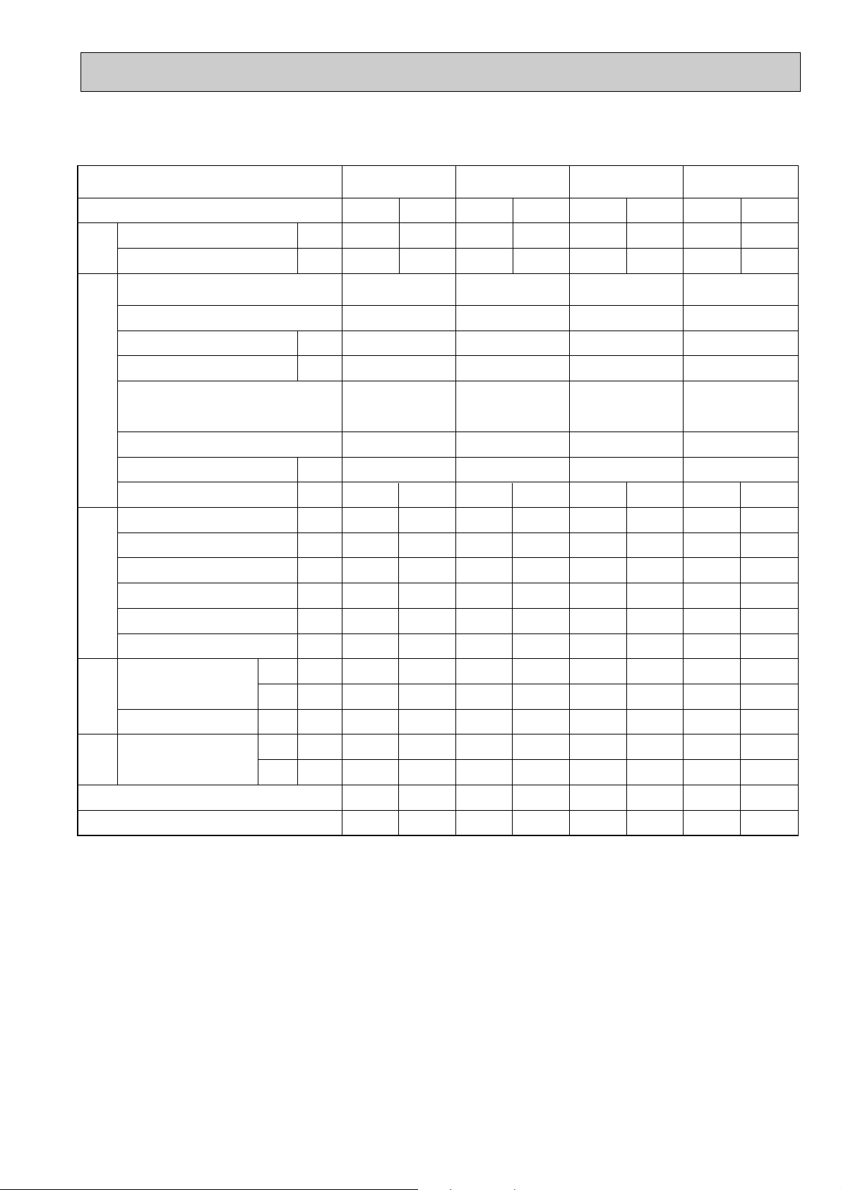
Representative matching
PLA-RP71AA PLA-RP100AA
PLA-RP125AA
PLA-RP140AA
Mode
Capacity
TotalElectrical circuitRefrigerant circuitIndoor side
Input
Indoor unit
Phase , Hz
Volts
Amperes
Outdoor unit
Phase , Hz
Volts
Amperes
Discharge pressure
Suction pressure
Discharge temperature
Condensing temperature
Cooling
W
7,700
kW
V
A
V
A
MPa
MPa
°C
°C
3.42
PLA-RP71AA PLA-RP100AA
PUH-P71VGAA.UK
PUH-P71YGAA.UK
15.55/4.64
2.30
0.47
81
44
Heating
9,200
1 , 50
230
0.79
1/3 , 50
230/400
15.84/4.74
3.48
2.38
0.39
88
45
Cooling
9,600
3.68
PUH-P100VGAA.UK
PUH-P100YGAA.UK
16.33/4.59
1.98
0.54
71
42
Heating
10,500
3.91
1 , 50
230
1.25
1/3 , 50
230/400
17.43/4.96
2.12
0.42
75
47
Cooling
13,300
5.09
PLA-RP125AA
PUH-P125YGAA.UK
6.44
2.11
0.48
71
41
Heating
15,600
5.54
1 , 50
230
1.64
3 , 50
400
7.16
2.39
0.42
79
44
Cooling
14,200
5.90
PLA-RP140AA
PUH-P140YGAA.UK
7.73
2.27
0.45
81
45
Heating
17,000
6.35
1 , 50
230
1.64
3 , 50
400
8.44
2.36
0.41
84
46
Suction temperature
Ref. pipe length
Intake air temperature
Discharge air temperature
Intake air temperature
side
Outdoor
SHF
BF
D.B.
W.B.
D.B.
D.B.
W.B.
°C
m
°C
°C
°C
°C
°C
5
5
27
19
13.4
35
24
0.74
0.13
0
5
20
15
45.1
7
6
—
—
8
5
27
19
14.0
35
24
0.78
0.12
1
5
20
15
40.1
7
6
—
—
6
5
27
19
11.7
35
24
0.72
0.06
The unit of pressure has been changed to MPa based on international SI system.
The conversion factor is : 1(MPa)=10.2(kgf/ff)
0
5
20
15
48.7
7
6
—
—
2
5
27
19
11.3
35
24
0.69
0.09
-1
5
20
15
51.2
7
6
—
—
15
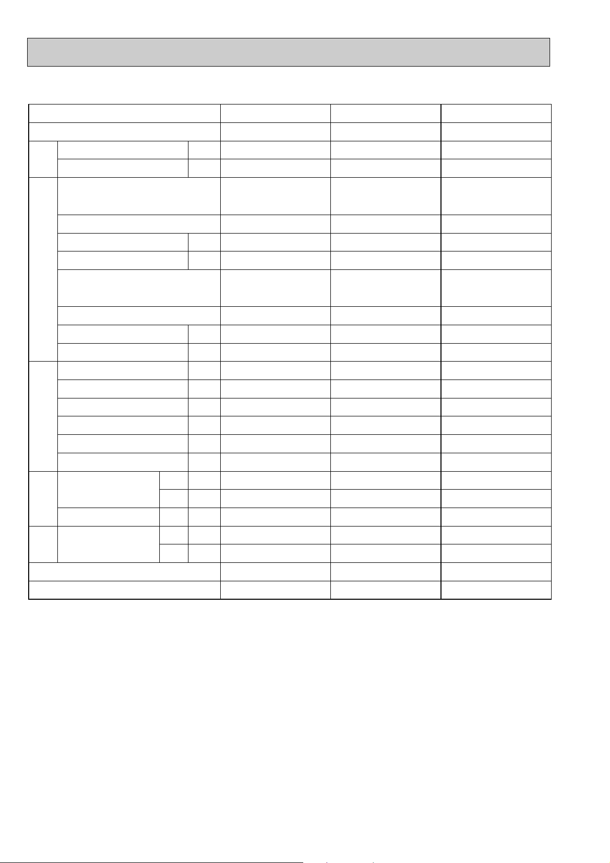
Cooling only type
Representative matching
Mode
Capacity
TotalElectrical circuitRefrigerant circuitIndoor side
Input
W
kW
PLA-RP35AA
Cooling
4,500
1.72
PLA-RP50AA
Cooling
5,600
2.53
PLA-RP60AA
Cooling
6,700
2.57
Indoor unit
Phase , Hz
Volts
Amperes
Outdoor unit
Phase , Hz
Volts
Amperes
Discharge pressure
Suction pressure
Discharge temperature
Condensing temperature
Suction temperature
Ref. pipe length
Intake air temperature
Discharge air temperature
Intake air temperature
side
Outdoor
SHF
BF
D.B.
W.B.
D.B.
D.B.
W.B.
V
A
V
A
MPa
MPa
°C
°C
°C
m
°C
°C
°C
°C
°C
PLA-RP35AA
1 , 50
230
0.79
PU-P35VGAA.UK
PU-P35YGAA.UK
1/3 , 50
230/400
7.43/1.94
2.01
0.59
78
48
11
5
27
19
14.1
35
24
0.75
0.16
PLA-RP50AA
1 , 50
230
0.79
PU-P50VGAA.UK
PU-P50YGAA.UK
1/3 , 50
230/400
11.30/3.23
2.48
0.59
85
55
10
5
27
19
14.6
35
24
0.82
0.12
PLA-RP60AA
1 , 50
230
0.79
PU-P60VGAA.UK
PU-P60YGAA.UK
1/3 , 50
230/400
11.49/3.29
2.18
0.54
80
51
9
5
27
19
12.9
35
24
0.72
0.14
The unit of pressure has been changed to MPa based on international SI system.
The conversion factor is : 1(MPa)=10.2(kgf/ff)
16
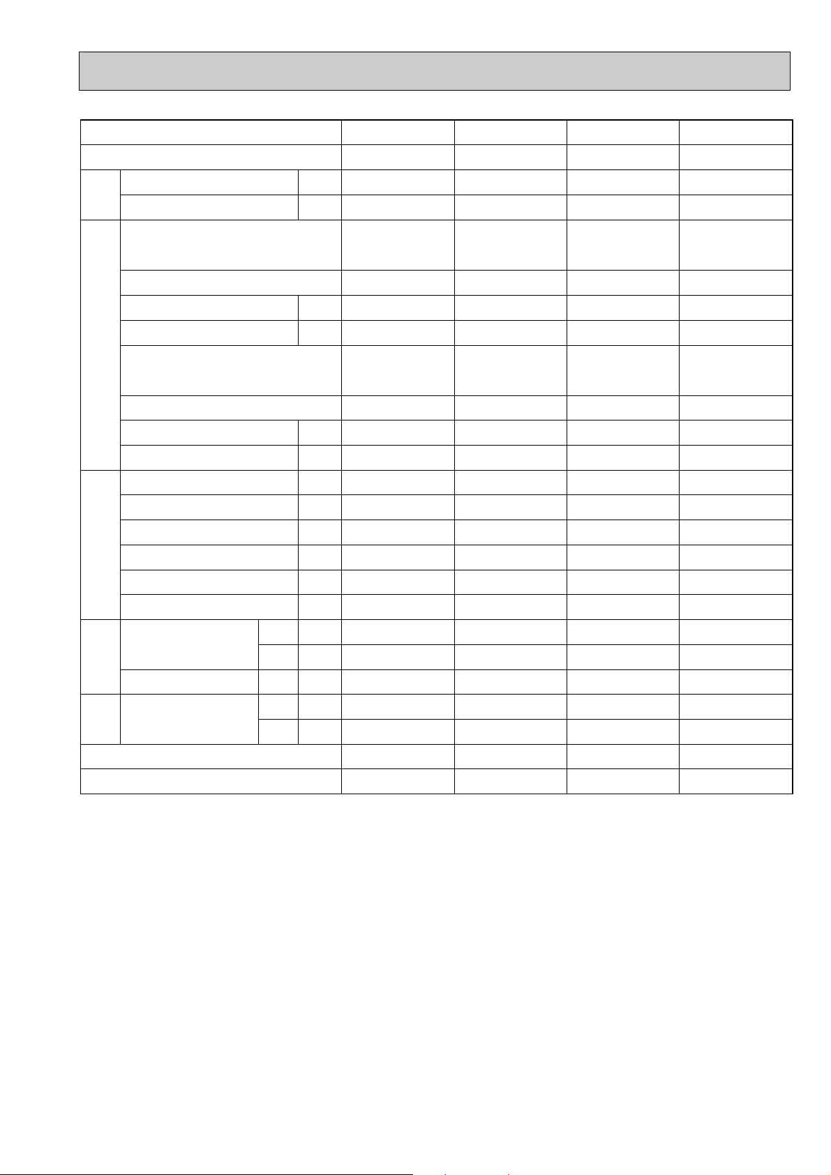
Representative matching
Mode
Capacity
TotalElectrical circuitRefrigerant circuitIndoor side
Input
W
kW
PLA-RP71AA PLA-RP100AA
Cooling
7,700
3.42
Cooling
9,200
3.68
PLA-RP125AA
Cooling
13,300
5.09
PLA-RP140AA
Cooling
14,200
5.90
Indoor unit
Phase , Hz
Volts
Amperes
Outdoor unit
Phase , Hz
Volts
Amperes
Discharge pressure
Suction pressure
Discharge temperature
Condensing temperature
Suction temperature
Ref. pipe length
Intake air temperature
Discharge air temperature
Intake air temperature
side
Outdoor
SHF
BF
D.B.
W.B.
D.B.
D.B.
W.B.
V
A
V
A
MPa
MPa
°C
°C
°C
m
°C
°C
°C
°C
°C
PLA-RP71AA PLA-RP100AA
1 , 50
230
0.79
PU-P71VGAA.UK
PU-P71YGAA.UK
1/3 , 50
230/400
15.55/4.64
2.30
0.47
81
44
5
5
27
19
13.4
35
24
0.74
0.13
1 , 50
230
1.25
PU-P100VGAA.UK
PU-P100YGAA.UK
1/3 , 50
230/400
16.33/4.59
1.98
0.54
71
42
8
5
27
19
14.0
35
24
0.78
0.12
PLA-RP125AA
1 , 50
230
1.64
PU-P125YGAA.UK PU-P140YGAA.UK
3 , 50
400
6.44
2.11
0.48
71
41
6
5
27
19
11.7
35
24
0.72
0.06
PLA-RP140AA
1 , 50
230
1.64
3 , 50
400
7.73
2.27
0.45
81
45
2
5
27
19
11.3
35
24
0.69
0.09
The unit of pressure has been changed to MPa based on international SI system.
The conversion factor is : 1(MPa)=10.2(kgf/ff)
17
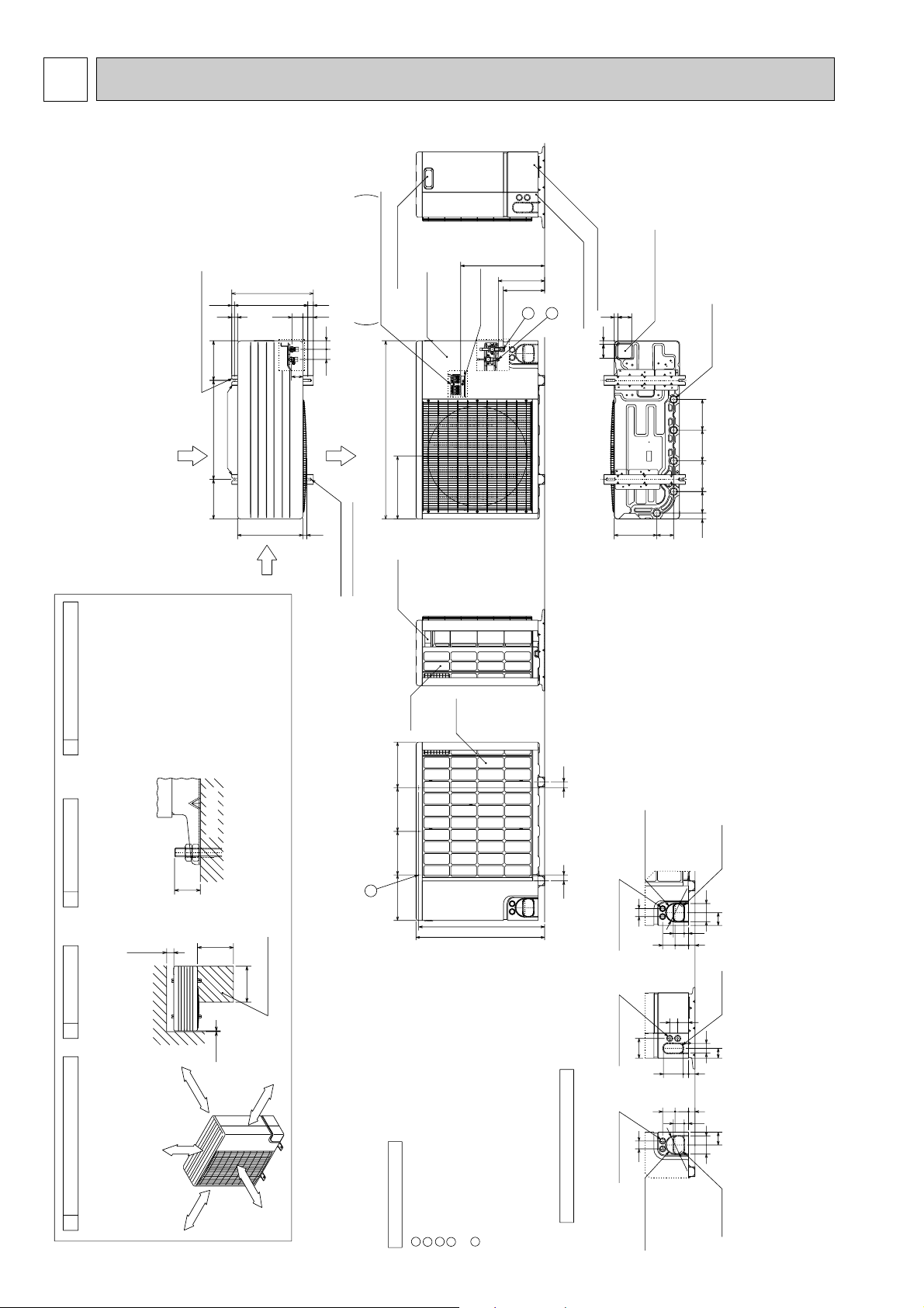
6 OUTLINES AND DIMENSIONS
321
T
SR
w1 248
w1 196
500
Power Supply Wiring Hole
(2-[27Knock-Out)
Right Piping Hole
(Knock-Out)
Power Supply Wiring Hole
(2-[27Knock-Out)
Terminal Connections
Left...Power supply Wiring
Right..Indoor/Outdoor Wiring
70
70
15515515510930
21585
Bottom Piping Hole
(Knock-Out)
Drain Hole
(5-[33holes)
18
18
424
900
318
Handle for moving
Earth Point
Service Panel
Front Piping Cover
Rear Piping Cover
1
2
Side Air
Intake
200200
53
370
(14)
412
29
330
55
4351
Rear Air Intake
Air Discharge
2-U Shaped notched holes
(Foundation Bolt M10)
2-12x40 oval holes
(Foundation Bolt M10)
20
28
58
Installation Feet
Rear
Air
Intake
Side
Air
Intake
Handle for
moving
3
230220220230
637
650
3030
Rear Trunking Hole
(Knock-Out)
< Rear Side >
Power Supply Wiring Hole
(2-[27Knock-Out)
40
33
22 55
68 63
65
92
Rear Piping Hole
(Knock-Out)
[
92
Piping Knock-Out Hole Details
. .
Refrigerant GAS pipe connection (FLARE)P35V(Y)GAA: [15.88 (5/8F)
. .
Refrigerant LIQUID pipe connection (FLARE)P35V(Y)GAA: [9.52 (3/8F)
. .
Height of STOP VALVE connection location.
1
2
< Right Side >< Front Side >
Explanation of Notes
40
68 63
22 55
65
92
33
27
100
50
50
100
33
[92
Front Piping Hole
(Knock-Out)
5540
3
. .
3-[3.6 holes (for securing the top of the unit)
These holes are provided for cases where the unit must
be secured by the base AND by the top surface.
Use Self Tapping screws 5 x L15 or less.(Obtained locally)
w1
. .
Refrigerant GAS pipe connection (FLARE)P25VGAA : [12.7 (1/2F)
. .
Refrigerant LIQUID pipe connection (FLARE)P25VGAA : [6.35 (1/4F)
1
2
O
ve
r 10m
m
FRE
E
O
ver 500m
m
Less than
30mm
FREE SPACE (Around the Unit)
Piping and wiring connections
can be made from 4 directions:
Front, Right, Rear and Below.
FOUNDATION BOLTS
1
The diagram below shows a
basic example.
Explanation of particular details are
given in the installation manuals etc.
SERVICE SPACE
Dimensions of space needed
for service access are
shown in the below diagram.
2
Over500
Over500
PIPING-WIRING DIRECTIONS
43
FOUNDATION
<Foundation bolt height>
Please secure the unit firmly
with 4 foundation (M10) bolts.
(Bolts and washers must be
purchased locally).
Service Space
O
ve
r 1
00m
m
O
ver 1
0m
m
Over10
Over100
OUTDOOR UNIT
PUH-P25VGAA.UK
PUH-P35VGAA.UK
PUH-P35YGAA.UK
PU-P35VGAA.UK
PU-P35YGAA.UK
Unit : mm
18
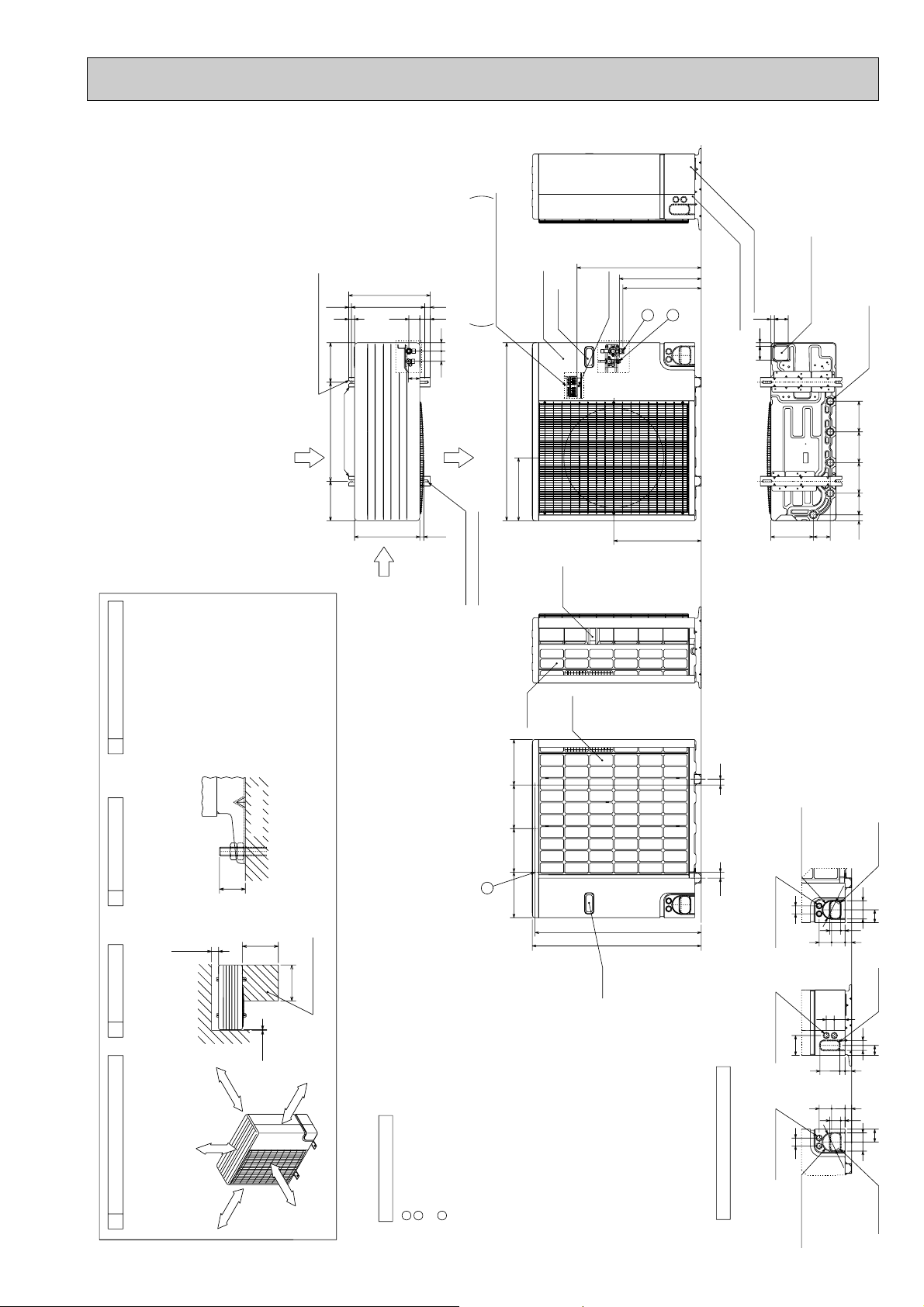
PUH-P50VGAA.UK
PUH-P50YGAA.UK
PUH-P60VGAA.UK
PUH-P60YGAA.UK
PUH-P71VGAA.UK
PUH-P71YGAA.UK
PU-P50VGAA.UK
PU-P50YGAA.UK
PU-P60VGAA.UK
PU-P60YGAA.UK
PU-P71VGAA.UK
PU-P71YGAA.UK
412
(14)
29
200500200
2-U Shaped notched holes
(Foundation Bolt M10)
370
55
28
53
43
51
58
Terminal Connections
Left...Power supply Wiring
Right..Indoor/Outdoor Wiring
Service Panel
Handle
321TSR
Earth Point
627
Unit : mm
w1 428
w1 376
Rear Piping Cover
Bottom Piping Hole
1
2
Front Piping Cover
18
70
(Knock-Out)
70
18
Drain Hole
(5-[33holes)
PIPING-WIRING DIRECTIONS
4
Piping and wiring connections
can be made from 4 directions:
Front, Right, Rear and Below.
FOUNDATION
FOUNDATION BOLTS
3
Please secure the unit firmly
with 4 foundation (M10) bolts.
(Bolts and washers must be
purchased locally).
30mm
Less than
<Foundation bolt height>
Over100
Rear Air Intake
Over500
Installation Feet
Side Air
Intake
330
Air Discharge
20
2-12x40 oval holes
(Foundation Bolt M10)
900
318
442
21585
15515515510930
Handle
Rear
Air
Intake
Intake
855
840
3030
Rear Trunking Hole
(Knock-Out)
< Rear Side >
40
Power Supply Wiring Hole
(2-[27Knock-Out)
92
[
68 63
Rear Piping Hole
(Knock-Out)
92
65
22 55
33
Side
Air
230220220230
3
SERVICE SPACE
2
Dimensions of space needed
for service access are
shown in the below diagram.
m
FRE
FREE SPACE (Around the Unit)
The diagram below shows a
basic example.
Explanation of particular details are
1
given in the installation manuals etc.
ver 10m
O
E
ver 100m
O
m
Over10
m
00m
Over500
r 10m
ve
O
ver 5
O
Service Space
m
Refrigerant LIQUID pipe connection (FLARE) [9.52 (3/8F)
Height of STOP VALVE connection location.
3-[3.6 holes (for securing the top of the unit)
Refrigerant GAS pipe connection (FLARE) [15.88 (5/8F)
. . .
. . .
. . .
These holes are provided for cases where the unit must
. . .
1w12
Explanation of Notes
be secured by the base AND by the top surface together.
3
19
Use Self Tapping screws 5 x L15 or less.
(Obtained Locally)
Handle
Right Piping Hole
5540
100
50
33
27
68 63
33
22 55
92
[92
< Right Side >
100
Power Supply Wiring Hole
(2-[27Knock-Out)
40
< Front Side >
Power Supply Wiring Hole
(2-[27Knock-Out)
Piping Knock-Out Hole Details
Front Trunking Hole
(Knock-Out)
Front Piping Hole
(Knock-Out)
50
65
(Knock-Out)
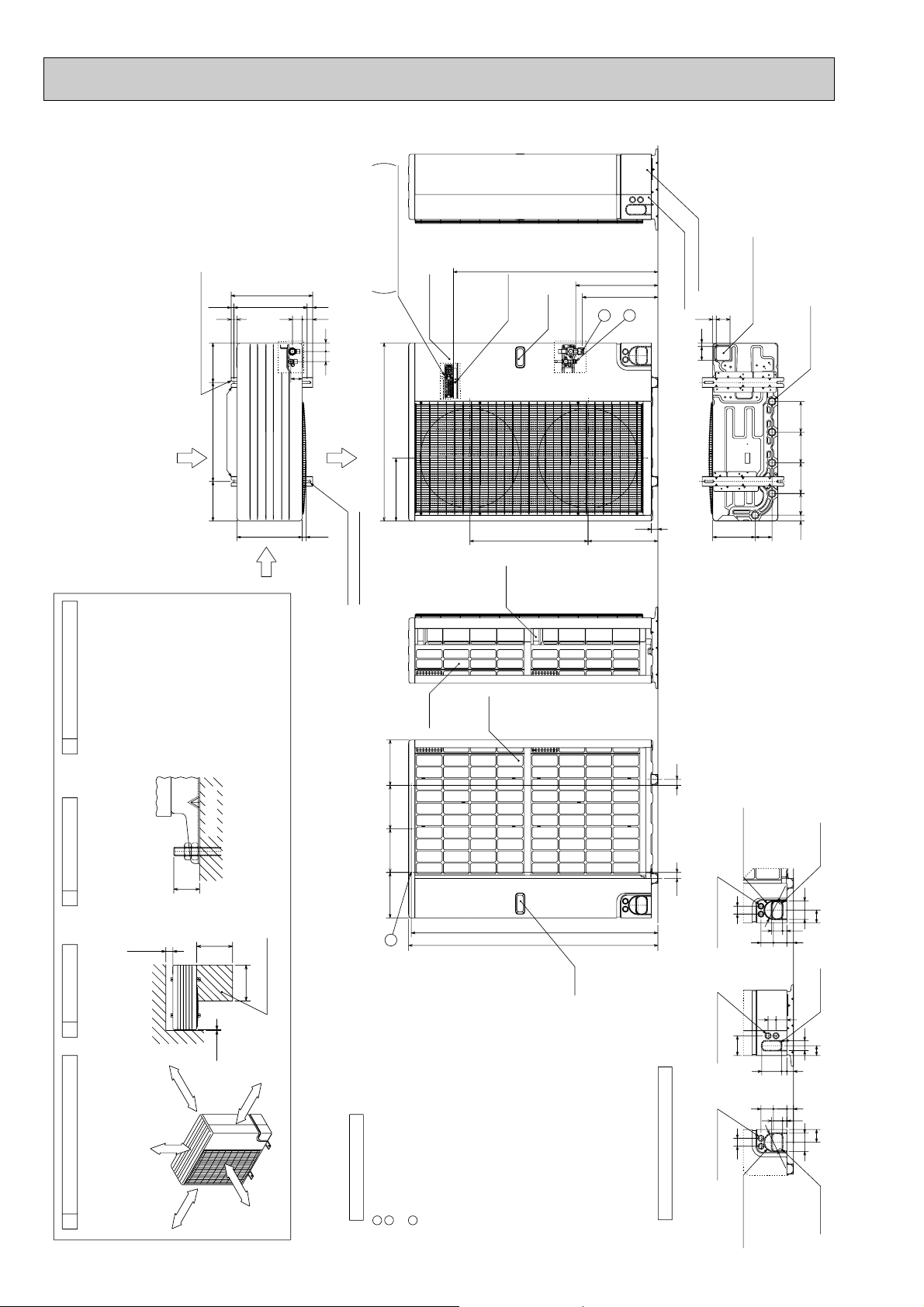
PUH-P100VGAA.UK
4
PIPING-WIRING DIRECTIONS
3
FOUNDATION BOLTS
FOUNDATION
Piping and wiring connections
can be made from 4 directions:
Front, Right, Rear and Below.
SERVICE SPACE
Please secure the unit firmly
with 4 foundation (M10) bolts.
(Bolts and washers must be
purchased locally).
30mm
<Foundation bolt height>
Less than
Over500
Over100
Service Space
Over500
1
FREE SPACE (Around the Unit)
Dimensions of space needed
for service access are
shown in the below diagram.
2
The diagram below shows a
basic example.
Explanation of particular details are
given in the installation manuals etc.
Over10
O
ver 10m
m
FRE
E
O
v
er 5
00
m
m
O
ver 100m
m
O
ver 10m
m
Explanation of Notes
. . .
Refrigerant GAS pipe connection(FLARE) [19.05 (3/4F)
. . .
Refrigerant LIQUID pipe connection(FLARE) [9.52 (3/8F)
. . .
Height of STOP VALVE connection location.
. . .
3-[3.6 holes (for securing the top of the unit)
These holes are provided for cases where the unit must
be secured by the base AND by the top surface together.
Use Self Tapping screws 5 x L15 or less.
(Obtained Locally)
3
2
w1
1
PUH-P100YGAA.UK
PU-P100VGAA.UK
PU-P100YGAA.UK
Unit : mm
29
200500200
2-U Shaped notched holes
(Foundation Bolt M10)
Installation Feet
Rear Air Intake
Side Air
Intake
370 (14)
330
412
50
58
Terminal Connections
28
53
4351
Air Discharge
20
2-12x40 oval holes
(Foundation Bolt M10)
Left...Power supply Wiring
Right..Indoor/Outdoor Wiring
Service Panel
900
318
Rear
Side
Air
Intake
Air
Intake
Earth Point
598
Handle
Handle
1033
W1 428
W1 376
1
2
33
352
Rear Piping Cover
Front Piping Cover
70
18
70 18
Bottom Piping Hole
(Knock-Out)
85 215
Drain Hole
(5-[33Holes)
30 109 155 155 155
230220220
230
3030
Rear Piping Hole
92
[
6368
5522
(Knock-Out)
92
65
33
Rear Trunking Hole
(Knock-Out)
< Rear Side >
3
1246
1260
40
Power Supply Wiring Hole
(2-[27Knock-Out)
Handle
Right Piping Hole
(Knock-Out)
4055
1002733
6368
5522
[92
50
50
33
65
92
< Right Side >
100
Power Supply Wiring Hole
(2-[27Knock-Out)
40
< Front Side >
Power Supply Wiring Hole
(2-[27Knock-Out)
Piping Knock-Out Hole Details
Front Piping Hole
Front Trunking Hole
(Knock-Out)
(Knock-Out)
20
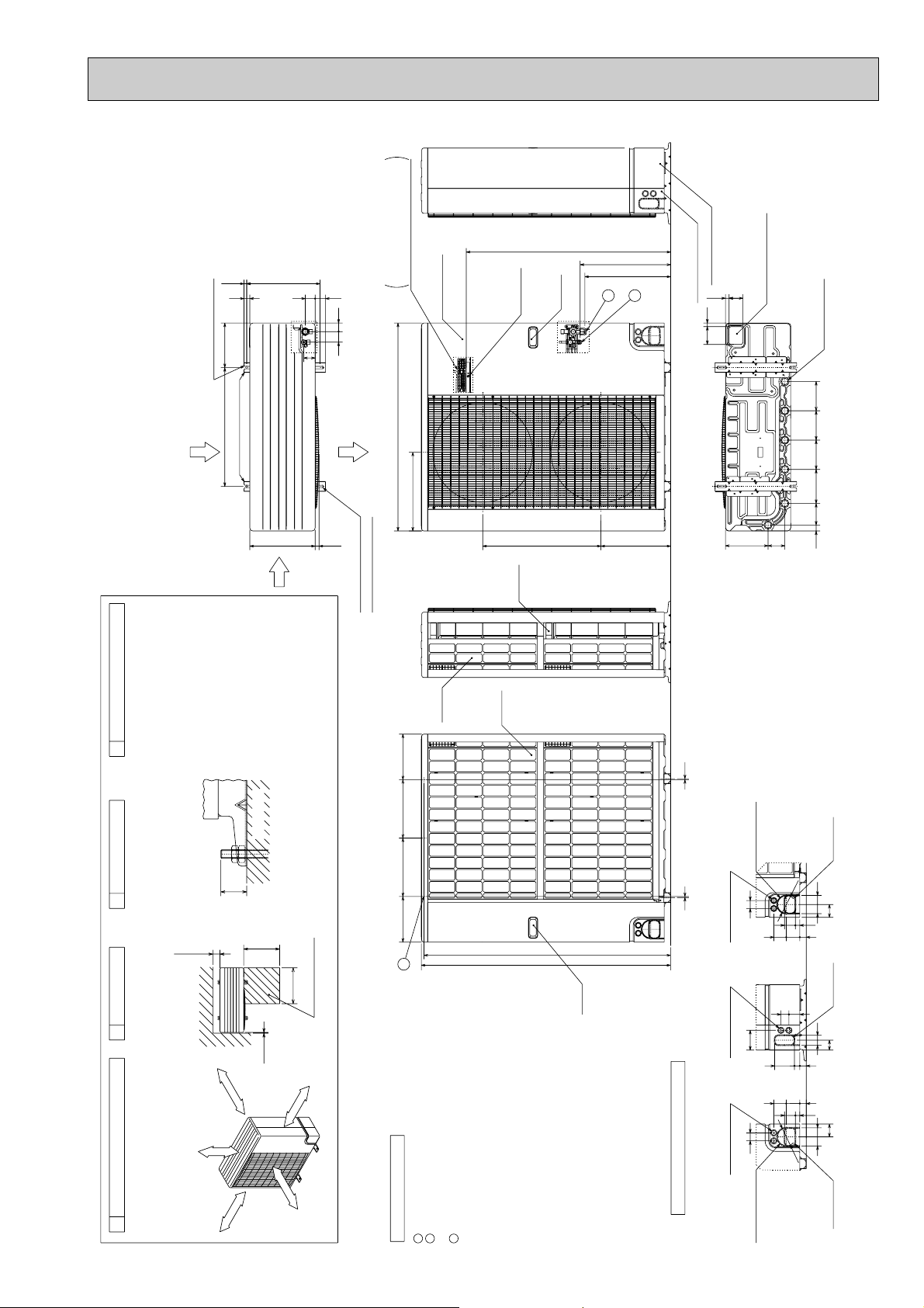
PUH-P125YGAA.UK
PUH-P140YGAA.UK
PU-P125YGAA.UK
PU-P140YGAA.UK
Unit : mm
29
225600
2-U Shaped notched holes
(Foundation Bolt M10)
Installation Feet
Rear Air Intake
Side Air
Intake
370 (14)
330
50
58
Terminal Connections
53
4453
Air Discharge
20
2-12x40 oval holes
(Foundation Bolt M10)
Left...Power supply Wiring
Right..Indoor/Outdoor Wiring
Service Panel
1050
398
Earth Point
598
Handle
1033
Handle
w1 478
w1 422
1
2
352
Rear Piping Cover
Bottom Piping Hole
70 18
Front Piping Cover
1870
21585
(Knock-Out)
Drain Hole
(5-[33Holes)
14814814817230 109
PIPING-WIRING DIRECTIONS
4
Piping and wiring connections
can be made from 4 directions:
Front, Right, Rear and Below.
FOUNDATION
FOUNDATION BOLTS
Please secure the unit firmly
with 4 foundation (M10) bolts.
(Bolts and washers must be
purchased locally).
30mm
Less than
<Foundation bolt height>
Over100
Over500
Over500
Service Space
SERVICE SPACE
23
Dimensions of space needed
for service access are
shown in the below diagram.
Over10
m
m
ver 10m
O
ver 500m
O
m
FRE
E
FREE SPACE (Around the Unit)
The diagram below shows a
basic example.
Explanation of particular details are
1
given in the installation manuals etc.
v
O
er 10m
ver 100m
O
m
Side
Air
230295295230
3
Refrigerant GAS pipe connection(FLARE) [19.05 (3/4F)
. . .
Explanation of Notes
1
Rear
Intake
Refrigerant LIQUID pipe connection(FLARE) [9.52 (3/8F)
Height of STOP VALVE connection location.
3-[3.6 holes (for securing the top of the unit)
. . .
. . .
. . .
These holes are provided for cases where the unit must
2
be secured by the base AND by the top surface together.
3
w1
Air
Intake
1246
1260
Handle
Use Self Tapping screws 5 x L15 or less.
(Obtained Locally)
55
Rear Trunking Hole
(Knock-Out)
92
92
[
< Rear Side >
40
Power Supply Wiring Hole
(2-[27Knock-Out)
< Right Side >
100
Power Supply Wiring Hole
(2-[27Knock-Out)
40
< Front Side >
Power Supply Wiring Hole
(2-[27Knock-Out)
5522
6368
4055
1002733
6368
5522
[92
33
50
33
92
Piping Knock-Out Hole Details
Front Trunking Hole
(Knock-Out)
Rear Piping Hole
(Knock-Out)
65
Right Piping Hole
(Knock-Out)
50
65
Front Piping Hole
(Knock-Out)
21
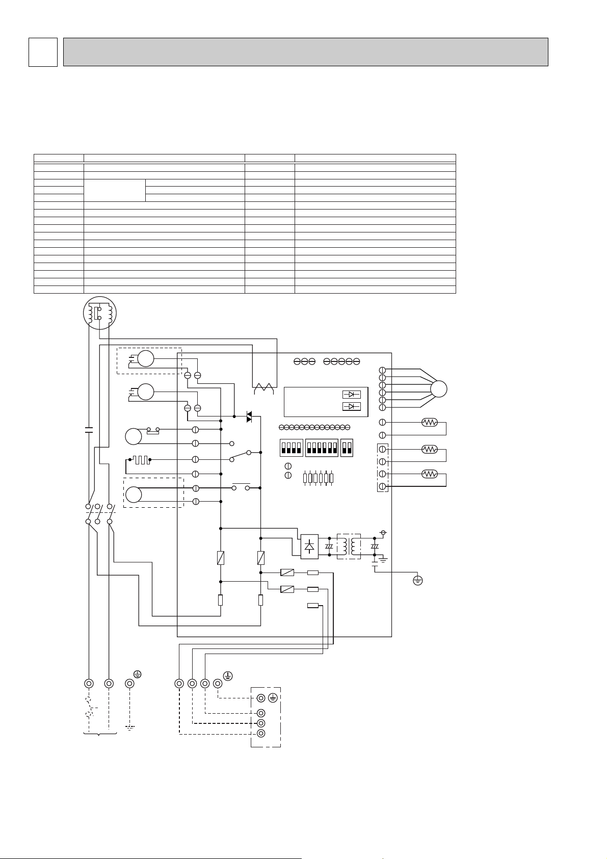
<Notes when servicing>
Some fastening terminals have a lock mechanism: When removing the fastening terminal, push the projection (locking lever) on the terminal with
your finger and pull it out.
SYMBOL NAME SYMBOL NAME
MC COMPRESSOR (INNER THERMOSTAT)
MF FAN MOTOR (INNER THERMOSTAT)
TH3 THERMISTOR LIQUID TEMP
TH4 DISCHARGE TEMP
TH6 COND. / EVA. TEMP
C3 MF CAPACITOR
C4 MF CAPACITOR
C5 MC CAPACITOR
CH CRANKCASE HEATER
52C MC CONTACTOR
21S4 4-WAY VALVE SOLENOID COIL
63H HIGH PRESSURE PROTECT SWITCH
49C INNER THERMOSTAT FOR MC
TB1 TERMINAL BLOCK
LEV LINEAR EXPANSION VALVE
TB2 TERMINAL BLOCK
O.B OUTDOOR CONTROLLER BOARD
FUSE1 (O.B) FUSE (6.3A)
FUSE2 (O.B) FUSE (6.3A)
FUSE3 (O.B) FUSE (6.3A)
FUSE4 (O.B) FUSE (6.3A)
X51 (O.B) MC/CH RELAY
X52 (O.B) 21S4 RELAY
F.C (O.B) FAN CONTROLLER
SW1 (O.B) GROUP NUMBER ADDRESS
SW4 (O.B) TEST RUN
SW5 (O.B) FUNCTION SELECTION
J1)~J6 (O.B) MODEL SELECTION
T (O.B) TRANSFORMER
CT (O.B) CURRENT TRANS
LED1 (O.B)
OPERATION CHECK DISPLAY LED
LED2 (O.B)
OPERATION CHECK DISPLAY LED
CN31 (O.B) EMERGENCY OPERATION CONNECTER
O.B
INDOOR
UNIT
SCR
MC
R
E
D
W
H
T
B
L
U
R
E
D
Y
L
W
O
R
N
B
R
N
B
L
U
C3
WHT
BLK
WHT
WHT
BRN
BRN
RED
BLU
49C
J1J2J3J4J5
J6
MF
LEV
CT
MF3
(WHT)
C4
*1
*1 PU(H)-P100VGAA MODEL ONLY
*2 PUH-P25~ P100VGAA MODEL ONLY
WHT
BLK
MF
MF4
(WHT)
52C
(PNK)
CH
(BLU)
52C
S1
S1
SW1 SW4
SW5
CNM
LED1 (GRN)
LED2 (RED)
S1
TB4
POWER SUPPLY
~/ N
230V 50Hz
S2
S2
S2
S3
S3
FUSE3
FUSE4
S3
a
b
63H
CH
52C
TB1
TB2
LN
T
OFF
ON
CNLEV
(WHT)
CNVMNT
(WHT)
CNMNT
(WHT)
TH4
(WHT)
TH3/TH6
(RED)
RED
BLU
BLK
GRY
BLK
ORN
YLW
WHT
BRN
TH4
TH6
TH3
CN31
F.C
X51
C5
2
/
T
1
6
/
T
3
1
/
L
1
5
/
L
3
4/S
R
FUSE2
FUSE1
BLU
BLU
21S4
(GRN)
21S4
X52
*2
7 WIRING DIAGRAM
PUH-P25VGAA.UK PUH-P35VGAA.UK PUH-P50VGAA.UK PUH-P60VGAA.UK
PUH-P71VGAA.UK PUH-P100VGAA.UK
PU-P35VGAA.UK PU-P50VGAA.UK PU-P60VGAA.UK PU-P71VGAA.UK
PU-P100VGAA.UK
22
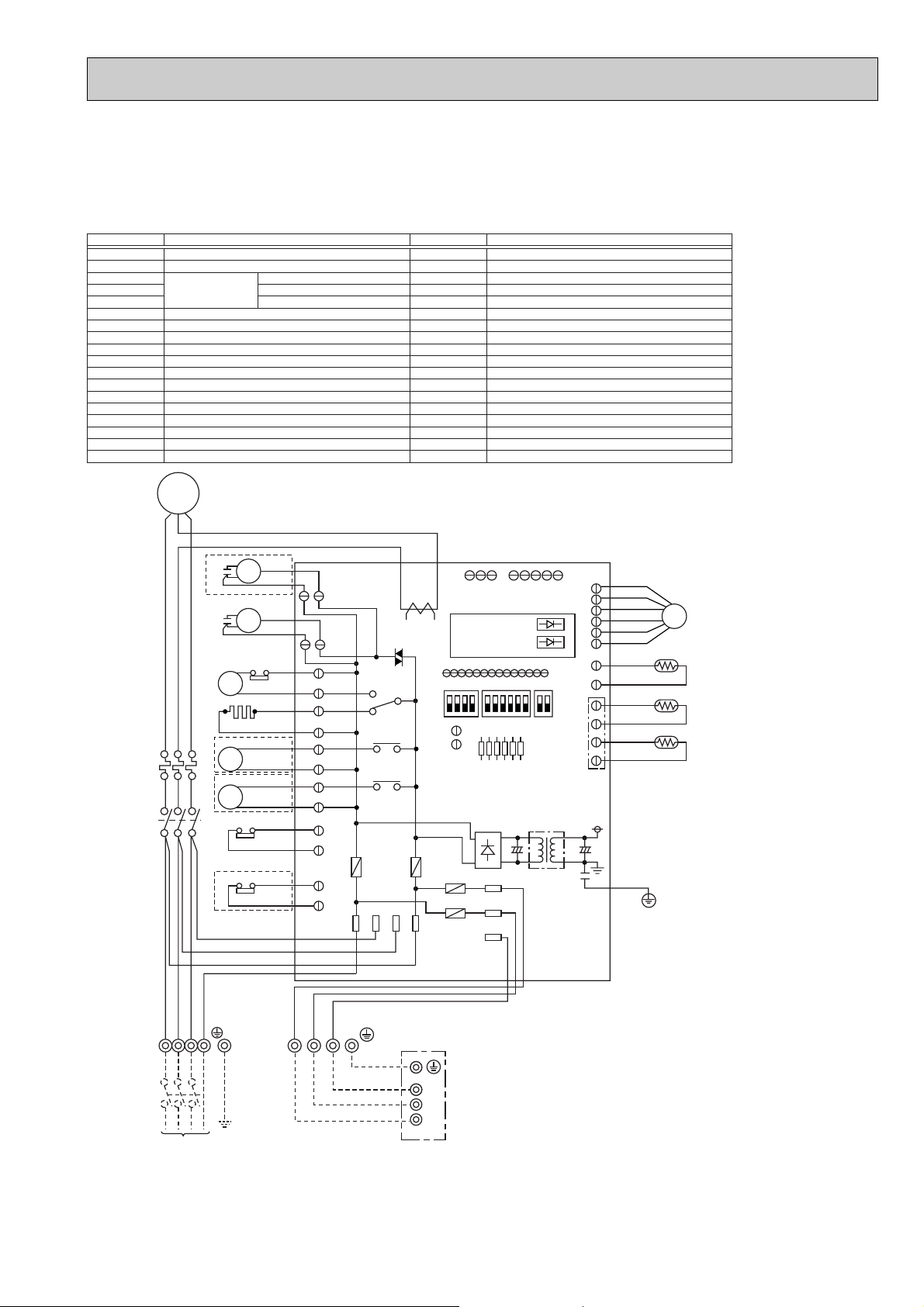
PUH-P35YGAA.UK PUH-P50YGAA.UK PUH-P60YGAA.UK PUH-P71YGAA.UK
PUH-P100YGAA.UK PUH-P125YGAA.UK PUH-P140YGAA.UK
PU-P35YGAA.UK PU-P50YGAA.UK PU-P60YGAA-UK PU-P71YGAA.UK
PU-P100YGAA.UK PU-P125YGAA.UK PU-P140YGAA.UK
SYMBOL NAME SYMBOL NAME
MC COMPRESSOR
MF FAN MOTOR (INNER THERMOSTAT)
TH3 THERMISTOR LIQUID TEMP
TH4 DISCHARGE TEMP
TH6 COND. / EVA. TEMP
C3 MF CAPACITOR
C4 MF CAPACITOR
CH CRANKCASE HEATER
52C MC CONTACTOR
21S4 4-WAY VALVE SOLENOID COIL
SV BYPASS VALVE SOLENOID COIL
63H HIGH PRESSURE PROTECT SWITCH
51C THERMAL RELAY
TB1 TERMINAL BLOCK
LEV LINEAR EXPANSION VALVE
TB2 TERMINAL BLOCK
63L LOW PRESSURE PROTECT SWITCH
MC
UVW
R
W
B
E
H
L
T
K
6
4
/
/
T
T
3
2
51C
52C
5
3
/
/
L
L
3
2
BLK
WHT
RED
W
B
B
H
L
L
T
K
U
3N~
400V 50Hz
C4
*2
C3
52C
CH
*4
21S4
*1
*3
D
2
/
T
1
1
/
L
1
R
E
D
L1 L2 L3 N
TB1
POWER SUPPLY
<Notes when servicing>
Some fastening terminals have a lock mechanism: When removing the fastening terminal, push the projection (locking lever) on the terminal with
your finger and pull it out.
SV
PE
MF
MF
a
b
51C
63L
63H
WHT
BLK
WHT
BLK
BRN
BRN
WHT
WHT
BLU
BLU
BLK
BLK
ORN
ORN
WHT
WHT
TB2
S1
Y
L
W
(*1BLK)
(*1BLK)
O
R
N
S2
MF4
(WHT)
MF3
(WHT)
52C
(PNK)
(BLU)
21S4
(GRN)
(BLK)
51CM
(ORN)
(RED)
B
R
N
S3
CH
SV
FUSE2
63L
4/S
O.B OUTDOOR CONTROLLER BOARD
FUSE1 (O.B) FUSE (6.3A)
FUSE2 (O.B) FUSE (6.3A)
FUSE3 (O.B) FUSE (6.3A)
FUSE4 (O.B) FUSE (6.3A)
X51 (O.B) MC/CH RELAY
X52 (O.B) 21S4 RELAY
X53 (O.B) SV RELAY
F.C (O.B) FAN CONTROLLER
SW1 (O.B) GROUP NUMBER ADDRESS
SW4 (O.B) TEST RUN
SW5 (O.B) FUNCTION SELECTION
J1~J6 (O.B) MODEL SELECTION
T (O.B) TRANSFORMER
CT (O.B) CURRENT TRANS
LED1 (O.B) OPERATION CHECK DISPLAY LED
LED2 (O.B) OPERATION CHECK DISPLAY LED
CN31 (O.B) EMERGENCY OPERATION CONNECTER
O.B
X51
X52
X53
F.C
RST
CT
TB4
CNM
ON
OFF
FUSE1
S3
S2
S1
CNVMNT
SW5
CN31
FUSE4
FUSE3
INDOOR
UNIT
CNMNT
(WHT)
LED1 (GRN)
LED2 (RED)
SW1 SW4
J1J2J3J4J5
S1
S2
S3
(WHT)
J6
CNLEV
(WHT)
TH4
(WHT)
TH3/TH6
(RED)
T
*1 PUH-P125/140YGAA MODEL ONLY
*2 PU(H)-P100/125/140YGAA MODEL ONLY
*3 PU(H)-P125/140YGAA MODEL ONLY
*4 PUH-P35~ P140YGAA MODEL ONLY
BRN
RED
BLU
ORN
YLW
WHT
BLK
BLK
GRY
LEV
TH4
TH6
TH3
23
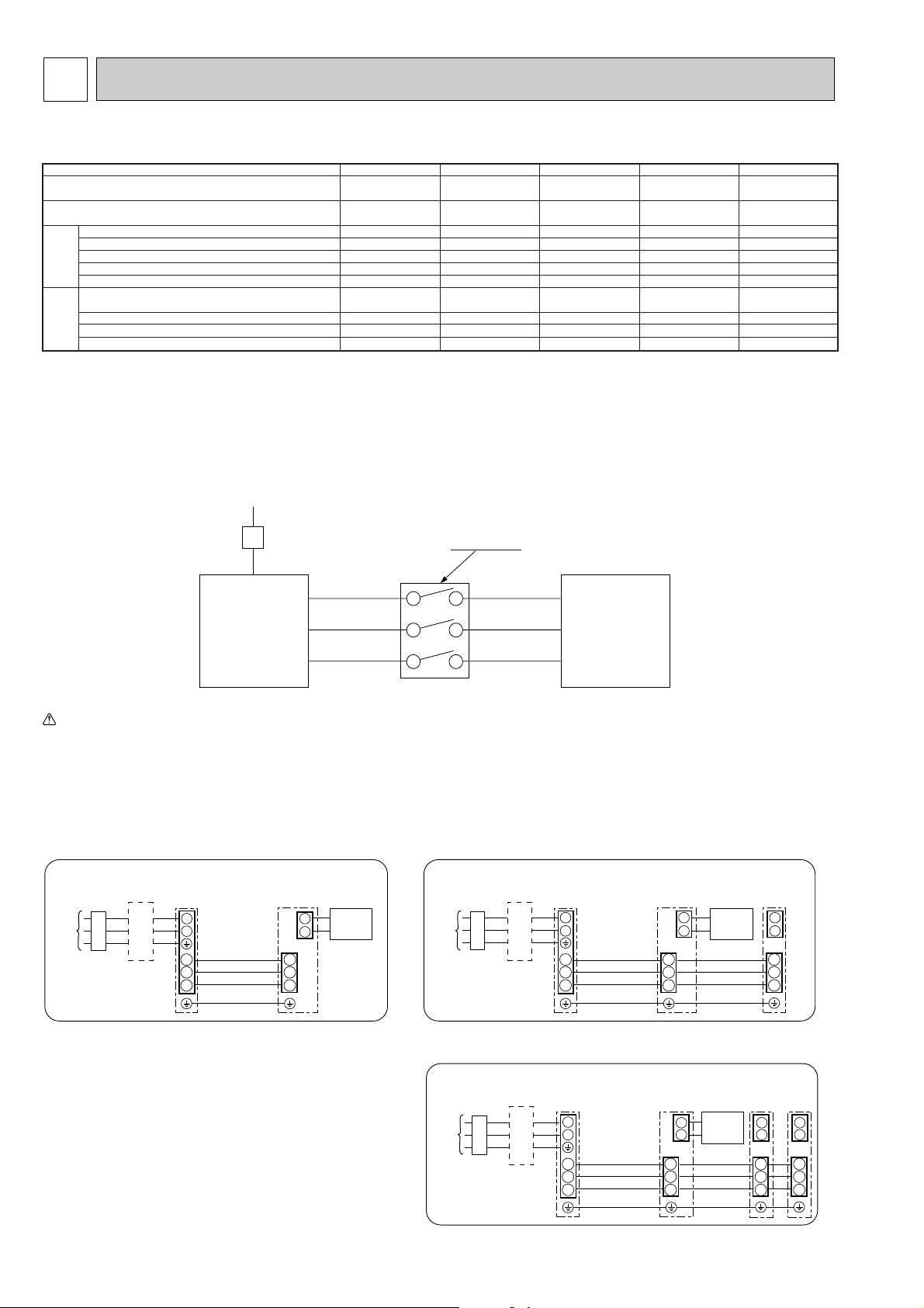
8 WIRING SPECIFICATIONS
1
2
S1
S2
S3
S1
S2
S3
Indoor/outdoor
unit connection
cable
Indoor
unit
Unit
power
supply
Outdoor
unit
Remote
controller
L
B
N
B Earth leakage breaker
C wiring circuit breaker or
isolating switch
C
B
B Earth leakage breaker
C wiring circuit breaker or
isolating switch
C
L
N
1
2
1
2
S1
Indoor
unit
S2
S3
S1
S2
S3
S1
S2
S3
Unit
power
supply
Indoor/outdoor
unit connection
cable
Indoor
unit
Outdoor
unit
Remote
controller
B
B Earth leakage breaker
C wiring circuit breaker or
isolating switch
C
1
2
1
2
1
2
S1
S2
S3
S1
S2
S3
S1
S2
S3
S1
S2
S3
Indoor/outdoor
connection cable
Indoor
unit
Unit
power
supply
Indoor
unit
Indoor
unit
Outdoor
unit
Remote
controller
L
N
8-1. FIELD ELECTRICAL WIRING (power wiring specifications)
Outdoor unit model
Outdoor unit power supply
Outdoor unit input capacity *1
Main switch (Breaker)
Outdoor unit power supply
)
2
Outdoor unit power supply earth
Indoor unit-Outdoor unit *2
Wiring
Indoor unit-Outdoor unit earth *2
Wire No. o
size (mm
Remote controller-Indoor unit *3
Outdoor unit L-N (single)
Outdoor unit L1-N, L2-N, L3-N (3 phase)
Indoor unit-Outdoor unit S1-S2 *4
Indoor unit-Outdoor unit S2-S3 *4
Circuit rating
Remote controller-Indoor unit *4
*1. A breaker with at least 3 mm contact separation in each poles shall be provided. Use non-fuse breaker (NF) or earth leakage breaker (NV).
*2. Refer to 8-2.
*3. The 10 m wire is attached in the remote controller accessory.
*4. The figures are NOT always against the ground.
S3 terminal has DC 24 V against S2 terminal. However between S3 and S1, these terminals are NOT electrically insulataed by the transformer or other device.
Notes: 1. Wiring size must comply with the applicable local and national code.
2. Power supply cords and Indoor/Outdoor unit connecting cords shall not be lighter than polychloroprene sheathed flexible cord. (Design 245 IEC 57)
3. Install an earth longer than other cables.
230V
Single phase
P25,35V P50,60V P71,100V P35,50,60,71,100Y P125, 140Y
~/N (single), 50 Hz, ~/N (single), 50 Hz, ~/N (single), 50 Hz, 3N ~ (3phase), 50 Hz,3N ~ (3phase), 50 Hz,
230 V 230 V 230 V 400 V400 V
16 A 25 A 32 A 16 A 25 A
2 o Min. 1.5 2 o Min. 2.5 2 o Min. 4 4 o Min. 1.5 4 o Min. 2.5
1 o Min. 1.5 1 o Min. 2.5 1 o Min. 4 1 o Min. 1.5 1 o Min. 1.5
3 o 1.5 (Polar) 3 o 1.5 (Polar) 3 o 1.5 (Polar) 3 o 1.5 (Polar) 3 o 1.5 (Polar)
1 o Min. 1.5 1 o Min. 1.5 1 o Min. 1.5 1 o Min. 1.5 1 o Min. 1.5
2 o 0.3 (Non-polar) 2 o 0.3 (Non-polar) 2 o 0.3 (Non-polar) 2 o 0.3 (Non-polar) 2 o 0.3 (Non-polar)
*4
AC 230 V AC 230 V AC 230 V AC 230 V AC 230 V
AC 230 V AC 230 V AC 230 V AC 230 V AC 230 V
DC 24 V DC 24 V DC 24 V DC 24 V DC 24 V
DC 12 V DC 12 V DC 12 V DC 12 V DC 12 V
A-Control
Outdoor Unit
Isolator
S1
S2
S3
3 poles isolator
S1
S2
S3
A-Control
Indoor Unit
Warning:
In case of A-control wiring, there is high v oltage potential on the S3 terminal caused by electrical circuit design that has no electrical insulation between power line
and communication signal line. Therefore, please turn off the main power supply when servicing. And do not touch the S1, S2, S3 terminals when the power is
energized. If isolator should be used between indoor unit and outdoor unit, please use 3-poles type.
1:1 system Synchronized twin and triple system Electrical wiring
• Synchronized twin
• Synchronized triple
24
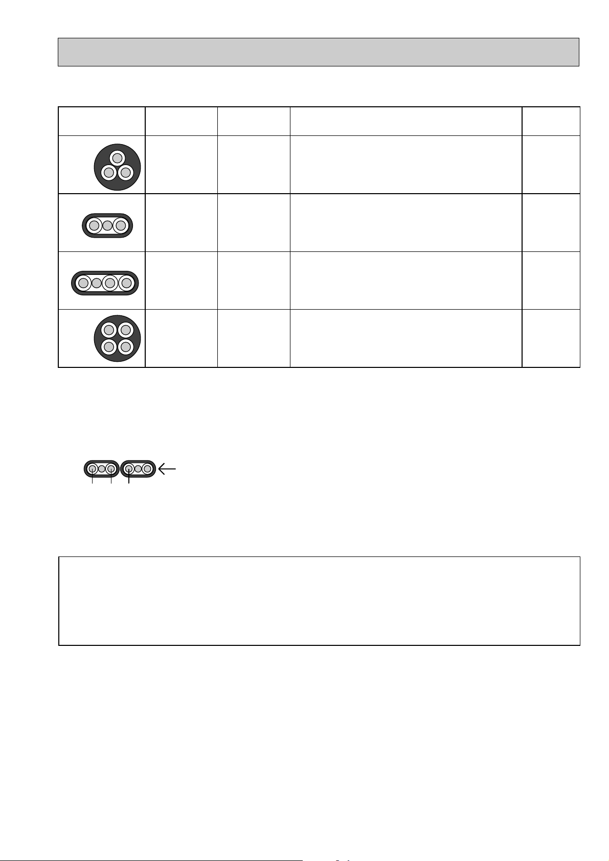
Cross section
of cable
Round
2.5
2.5
1.5
2.5
3
3
4
4
(50)
✽2
(45)
✽3
60
✽4
Not
applicable
✽5
Flat
✽1 : Power supply cords of appliances shall not be lighter than design 245 IEC or 227 IEC.
✽2 : In case that cable with stripe of yellow and green is available.
✽3 : In case of regular polarity connection (S1-S2-S3), wire size is 1.5mm
2
.
✽4 : In case of regular polarity connection (S1-S2-S3).
✽5 : In the flat cables are connected as this picture, they can be used up to 80m.
✽6 : Mentioned cable length is just a reference value.
It may be different depending on the condition of installation, Humidity or materials, etc.
Flat
Round
Wire size
(mm
2
)
Number
of wires
Clockwise : S1-S2-S3
w Pay attention to stripe of yellow and green
Clockwise : S1-S2-S3-Open
w Connect S1 and S3 to the opposite angle
Not applicable
(Because center wire has no cover finish)
From left to right : S1-Open-S2-S3
Polarity
L(m)
✽6
(3C Flat cable ✕ 2)
S1 S2 S3
Be sure to connect the indoor-outdoor connecting cables directly to the units (no intermediate
connections).
Intermediate connections can lead to communication errors if water enters the cables and causes
insufficient insulation to ground or a poor electrical contact at the intermediate connection point.
(If an intermediate connection is necessary, be sure to take measures to prevent water from entering
the cables.)
8-2. INDOOR-OUTDOOR CONNECTING CABLE
25
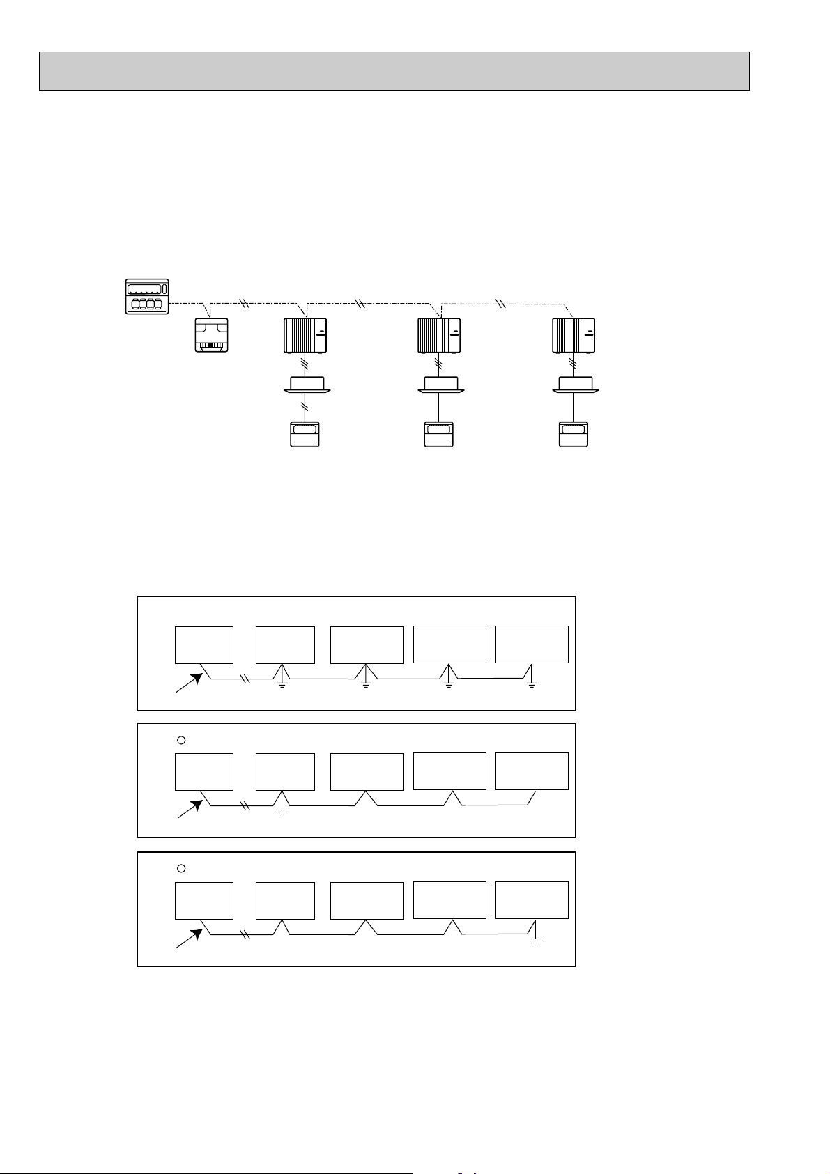
8-3. M-NET WIRING METHOD
Group
remote
controller
Refrigerant
address 00
M-NET
address 01
A-control
remote
controller
A-control
remote
controller
A-control
remote
controller
Refrigerant
address 00
M-NET
address 02
Refrigerant
address 00
M-NET
address 03
Power
supply
unit for
transmission
wire
Central
remote
controller
M-NET transmission wire
✕ Bad example (Multi spot grounding of shield wire)
Good example 1 (Single spot grounding of shield wire)
Power
supply
appliance
M-NET type
outdoor unit
Central
remote
controller
Power
supply
appliance
M-NET type
outdoor unit
M-NET type
outdoor unit
M-NET type
outdoor unit
M-NET transmission wire
M-NET type
outdoor unit
M-NET type
outdoor unit
Central
remote
controller
Power
supply
appliance
M-NET type
outdoor unit
M-NET transmission wire
M-NET type
outdoor unit
M-NET type
outdoor unit
Good example 2 (Single spot grounding of shield wire)
(Points to notice)
(1) Outside the unit, transmission wires should stay away from electric wires in order to prevent electromagnetic noise from
making an influence on the signal communication. Place them at intervals of more than 5cm. Do not put them in the same
conduit tube.
(2) Terminal block (TB7) for transmission wires should never be connected to 220~240V power supply. If it is connected,
electronic parts on M-NET p.c. board may be burn out.
(3) Use 2-core x 1.25mm2shield wire (CVVS, CPEVS) for the transmission wire. Transmission signals may not be sent or
received normally if different types of transmission wires are put together in the same multi-conductor cable. Never do this
because this may cause a malfunction.
It would be ok if M-NET wire (non-polar, 2-cores) is arranged in addition to the wiring for A-control.
(4) Ground only one of any appliances through M-NET transmission wire (shield wire). Communication error may occur due to
the influence of electromagnetic noise.
“Ed” error will appear on the LED display of outdoor unit.
“0403” error will appear on the central-control remote controller.
If there are more than two grounding spots on the shield wire, noise may enter into the shield wire because the ground wire
and shield wire form one circuit and the electric potential difference occurs due to the impedance difference among grounding spots. In case of single spot grounding, noise does not enter into the shield wire because the ground wire and shield
wire do not form one circuit.
To avoid communication errors caused by noise, make sure to observe the single spot grounding method described in the
installation manual.
26
1
2
3
4
5
6
7
8
9
0
1
2
3
4
5
6
7
8
9
0
1
2
3
4
5
6
7
8
9
0
1
2
3
4
5
6
7
8
9
0
1
2
3
4
5
6
7
8
9
0
1
2
3
4
5
6
7
8
9
0
12
~
50
M-NET Address No.
<Setting example>
Switng
setting
SW11
ones
digit
SW12
tens
digit
OFF
ON
1
2
3
4
5
6
1
2
3
4
5
6
1
2
3
4
5
6
1
2
3
4
5
6
1
2
3
4
5
6
1
2
3
4
5
6
1
2
3
4
5
6
1
2
3
4
5
6
1
2
3
4
5
6
1
2
3
4
5
6
1
2
3
4
5
6
1
2
3
4
5
6
1
2
3
4
5
6
1
2
3
4
5
6
1
2
3
4
5
6
1
2
3
4
5
6
0
Refrigerant
address
OFF
ON
8
OFF
ON
1
OFF
ON
9
OFF
ON
10
OFF
ON
11
OFF
ON
12
OFF
ON
13
OFF
ON
14
OFF
ON
15
OFF
ON
2
OFF
ON
3
OFF
ON
4
OFF
ON
5
OFF
ON
6
OFF
ON
7
System
controller
A-control
remote
controller
Group A Group B Group C
A-control
remote
controller
TB5
A-control
remote
controller
Refrigerant
address 00
M-NET
address 01
Refrigerant
address 00
M-NET
address 02
Refrigerant
address 01
M-NET
address 03
Refrigerant
address 00
M-NET
address 04
Power
supply
unit for
transmission
wire
A-control
remote
controller
A-control
remote
controller
TB5
Group A Group B
Refrigerant
address 00
M-NET
address 01
Refrigerant
address 01
M-NET
address 02
Refrigerant
address 00
M-NET
address 04
Refrigerant
address 01
M-NET
address 03
Refrigerant
address 02
M-NET
address 05
System
controller
Power
supply
unit for
transmission
wire
● M-NET wiring
(1) Use 2-core x 1.25mm
2
shield wire for electric wires.
(Excluding the case connecting to system controller.)
(2) Connect the wire to the M-NET terminal block.Connect one core of the
transmission wire (non-polar) to Aterminal and the other to B. Peel the
shield wire, twist the shield part to a string and connect it to S terminal.
(3) In the system which several outdoor units are being connected, the terminal
(A, B, S) on M-NET terminal block should be individually wired to the other
M-NET
terminal
block
ABS
Transmission
wire
Ground
wire
Shield
part
outdoor unit’s terminal, i.e. Ato A, B to B and S to S.In this case, choose one of those outdoor units and drive a screw
to fix an ground wire on the plate as shown on the right figure.
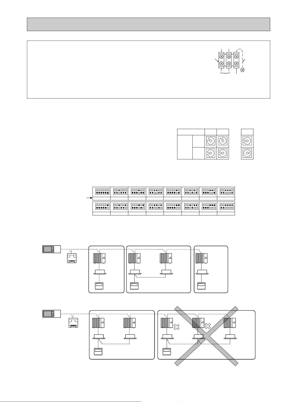
8-3-1. M-NET address setting
In A-control models, M-NET address and refrigerant address should be set only for the outdoor unit. Similar to Free Combo
system, there is no need to set the address of outdoor unit and remote controller. To construct a central control system, the
setting of M-NET address should be conducted only upon the outdoor unit. The setting range should be 1 to 50 (the same as
that of the indoor unit in Free Combo system), and the address number should be consecutively set in a same group.
Address number can be set by using rotary switches
(SW11 for ones digit and SW12 for tens digit), which
is located on the M-NET board of outdoor unit.
(Factory setting: all addresses are set to “0”.)
8-3-2. Refrigerant address setting
In case of multiple grouping system (multiple refrigerant circuits in one group), indoor units should be connected by remote
controller wiring (TB5) and the refrigerant address needs to be set. Leave the refrigerant addresses to “00” if the group setting is not conducted. Set the refrigerant address by using DIP SW1-3 to -6 on the outdoor controller board. [Factory setting:
all switches are OFF. (All refrigerant addresses are “00”.)]
8-3-3. Regulations in address settings
In case of multiple grouping system, M-NET and refrigerant address settings should be done as explained in the above section. Set the lowest number in the group for the outdoor unit whose refrigerant address is “00” as its M-NET address.
w Refrigerant addresses can be overlapped if they are in the different group.
w In group B, M-NET address of the outdoor unit whose refrigerant address is “00” is not set to the minimum in the group. As
“3” is right for this situation, the setting is wrong. Taking group A as a good sample, set the minimum M-NET address in
the group for the outdoor unit whose refrigerant address is “00”.
27
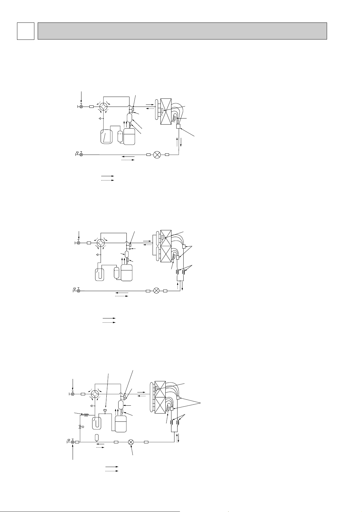
9
Service
port
Accumulator
Compressor
Refrigerant GAS pipe
19.05A({3/4")
Refrigerant LIQUID pipe
9.52A({3/8")
Stop valve
(with service port)
4-way valve
Service
port
High pressure
protect switch
Thermistor
(TH3)
Capillary tube
(O.D.4.0✕I.D.3.0-L350)✕2pcs
Refrigerant flow in cooling
Refrigerant flow in heating
Liner expansion valve
Thermistor
(TH4)
Muffler
Thermistor
(TH6)
Distributor
with
strainer
Ball valve
(#50)
Strainer
(#100)
Strainer
(#100)
Strainer
Service
port
Accumulator
Ball valve
Compressor
Refrigerant GAS pipe
P25···12.7A({1/2")
P35~P71···15.88A({5/8")
Refrigerant LIQUID pipe
P25···6.35A({1/4")
P35~P71···9.52A({3/8")
Stop valve
(with service port)
4-way valve
Service
port
High pressure
protect switch
Outdoor heat exchanger
Thermistor
(TH3)
Thermistor
(TH6)
Distributor
with
strainer
Muffler
Thermistor(TH4)
Linear expansion valve
Refrigerant flow in cooling
Refrigerant flow in heating
(#50)
Strainer
(#100)
Strainer
(#100)
Strainer
Service
port
Accumulator
Compressor
Refrigerant GAS pipe
19.05A({3/4")
Refrigerant LIQUID pipe
9.52A({3/8")
4-way
valve
Service
port
High pressure protect switch
Thermistor
(TH3)
Capillary tube
(O.D.4.0✕I.D.3.0-L200)✕2pcs
Drier
Liner expansion valve
Muffler
Thermistor
(TH4)
Thermistor
(TH6)
Distributor
with
strainer
Refrigerant flow in cooling
Refrigerant flow in heating
w1 : O.D.4.0✕I.D.2.0-L400(PUH-P125)
O.D.4.0✕I.D.3.0-L450(PUH-P140)
Ball valve
(#50)
Strainer
Strainer
(#100)
Strainer
(#100)
Strainer
(#50)
Low pressure protect
switch
Stop valve
(with service port)
Capillary
tube w1
REFRIGERANT SYSTEM DIAGRAM
PUH-P25VGAA.UK PUH-P35VGAA.UK PUH-P50VGAA.UK PUH-P60VGAA.UK
PUH-P71VGAA.UK
PUH-P35YGAA.UK PUH-P50YGAA.UK PUH-P60YGAA.UK PUH-P71YGAA.UK
<4-way valve solenoid coil>
Heating : ON
Cooling : OFF
PUH-P100VGAA.UK
PUH-P100YGAA.UK
PUH-P125YGAA.UK
PUH-P140YGAA.UK
28
Service
port
Accumulator
Compressor
Refrigerant GAS pipe
19.05A({3/4")
Refrigerant LIQUID pipe
9.52A({3/8")
Stop valve
(with service port)
Service
port
High pressure
protect switch
Thermistor
(TH3)
Capillary tube
(O.D.4.0✕I.D.3.0-R350)✕2pcs
Refrigerant flow in cooling
Liner expansion valve
Thermistor
(TH4)
Thermistor
(TH6)
Distributor
with
strainer
Ball valve
(#50)
Strainer
(#100)
Strainer
(#100)
Strainer
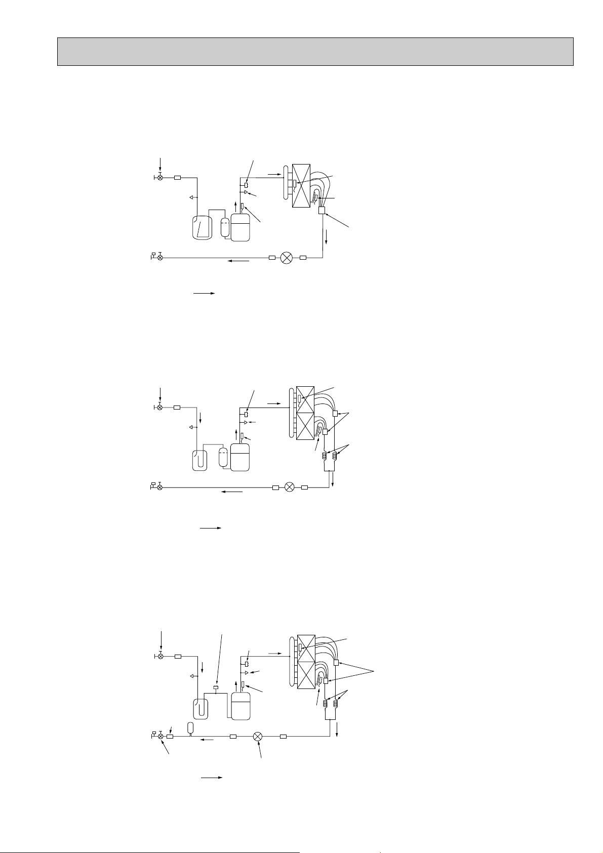
PU-P35VGAA.UK PU-P50VGAA.UK PU-P60VGAA.UK PU-P71VGAA.UK
Service
port
Accumulator
Compressor
Refrigerant GAS pipe
15.88A({5/8")
Refrigerant LIQUID pipe
9.52A({3/8")
Stop valve
(with service port)
Service
port
High pressure
protect switch
Outdoor heat exchanger
Thermistor
(TH3)
Thermistor
(TH6)
Distributor
with
strainer
Thermistor(TH4)
Linear expansion valve
Refrigerant flow in cooling
Ball valve
(#50)
Strainer
(#100)
Strainer
(#100)
Strainer
Service
port
Accumulator
Compressor
Refrigerant GAS pipe
19.05A({3/4")
Refrigerant LIQUID pipe
9.52A({3/8")
Service
port
High pressure
protect switch
Thermistor
(TH3)
Capillary tube
(O.D.4.0✕I.D.3.0-L200)✕2pcs
Drier
Thermistor
(TH4)
Thermistor
(TH6)
Distributor
with
strainer
Refrigerant flow in cooling
Stop valve
(with service port)
Liner expansion valve
Ball valve
(#50)
Strainer
Strainer
(#100)
Strainer
(#100)
(#50)
Strainer
Low pressure protect
switch
PU-P35YGAA.UK PU-P50YGAA.UK PU-P60YGAA.UK PU-P71YGAA.UK
PU-P100VGAA.UK
PU-P100YGAA.UK
PU-P125YGAA.UK
PU-P140YGAA.UK
29
10 TROUBLESHOOTING
Unit conditions at service
Error code
Actions to be taken for service (summary)
The inferior phenomenon is
reoccurring.
Displayed
Not displayed
Judge what is wrong and take a corrective action according
to “10-4. Self-diagnosis action table”.
Conduct trouble shooting and ascertain the cause of the
inferior phenomenon according to “10-5. Troubleshooting
by inferior phenomena”.
The inferior phenomenon is
not reoccurring.
Logged
Not logged
1Consider the temporary defects such as the work of
protection devices in the refrigerant circuit including
compressor, poor connection of wiring, noise and etc.
Re-check the symptom, and check the installation
environment, refrigerant amount, weather when the
inferior phenomenon occurred, matters related to wiring
and etc.
2Reset error code logs and restart the unit after finishing
service.
3There is no abnormality concerning of parts such as
electrical component, controller board, remote controller
and etc.
1Re-check the abnormal symptom.
2Conduct trouble shooting and ascertain the cause of the
inferior phenomenon according to “10-5. Troubleshooting
by inferior phenomena”.
3Continue to operate unit for the time being if the cause
is not ascertained.
4There is no abnormality concerning of parts such as
electrical component, controller board, remote controller
and etc.
10-1. TROUBLESHOOTING
<Error code display by self-diagnosis and actions to be taken for service (summary)>
Present and past error codes are logged and displayed on the wired remote controller and control board of outdoor unit.
Actions to be taken for service, which depends on whether or not the inferior phenomenon is reoccurring at service, are summarized in the table below. Check the contents below before investigating details.
10-2. CHECK POINT UNDER TEST RUN
(1) Before test run
• After installation of indoor and outdoor units, piping work and electric wiring work, re-check that there is no refrigerant leak-
age, loosened connections and incorrect polarity.
• Measure impedance between the ground and the power supply terminal block(L, N) on the outdoor unit by 500V Merger and
check that it is 1.0M" or over.
wDon’t use 500V Merger to indoor/outdoor connecting wire terminal block(S1, S2, S3) and remote controller terminal block
(1, 2). This may cause malfunction.
• Make sure that test run switch (SW4) is set to OFF before turning on power supply.
• Turn on power supply twelve hours before test run in order to protect compressor.
• For specific models which requires higher ceiling settings or auto-recovery feature from power failure, make proper changes
of settings referring to the description of “Selection of Functions through Remote Controller”.
Make sure to read operation manual before test run. (Especially items to secure safety.)
30
 Loading...