

Page 1
TECHNICAL & SERVICE MANUAL
[Model names]
PUH-8YKA
PUH-10YKA
No.HWE07040
SPLIT-TYPE, HEAT PUMP AIR CONDITIONERS
CONTENTS
1.
COMBINATION OF INDOOR AND OUTDOOR UNITS
···2
2. SAFETY FOR USE ·········································3
3. SAFETY PRECAUTIONS·······························5
4. DATA ·······························································7
5. SOUND DATA ·················································8
6. OUTLINES AND DIMENSIONS ······················9
7. WIRING DIAGRAM·······································10
8. REFRIGERANT SYSTEM DIAGRAM ···········11
9. SYSTEM CONTROL·····································12
10. TEST RUN·····················································14
11. CONTROL ·····················································16
12. GROUP CONTROL ·······································29
13.
NOTES FOR M-NET <MELANS> WIRING CONNECTION
····30
14. EMERGENCY OPERATION ··························32
15.
SELF-DIAGNOSIS AND TROUBLESHOOTING
···34
16. SIMPLE PARTS CHECK METHOD··············45
17. PARTS NAME ···············································46
18. OPTIONAL PARTS ·······································48
July 2007
Page 2
2
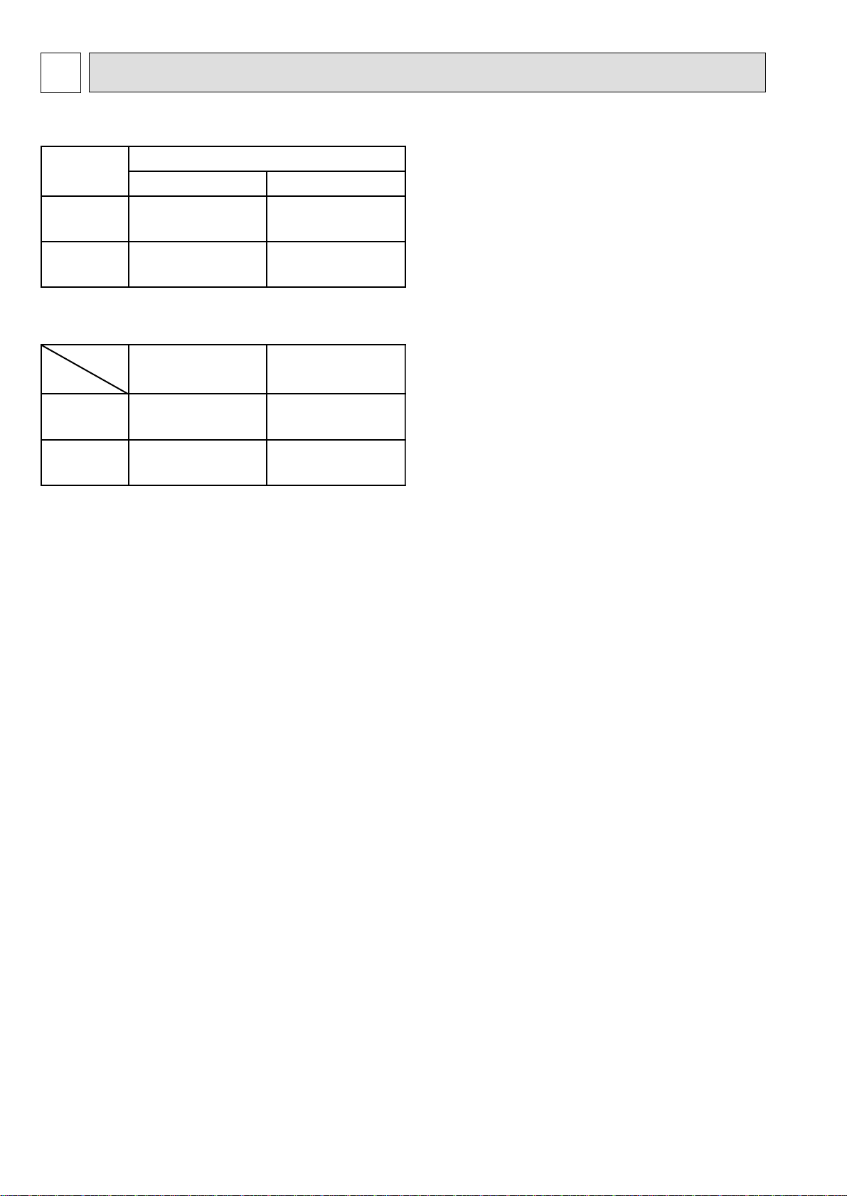
1 COMBINATION OF INDOOR AND OUTDOOR UNITS
Types of connected indoor units
Outdoor Unit List
Outdoor unit
PUH-8YKA
PUH-10YKA
Model name Service manual No.
PEH-8GA
PEH-16GA
PEH-10GA
PEH-20GA
Specification
Model name
PUH-8YKA
PUH-10YKA
PUH-8YKA.TH
PUH-10YKA.TH
Indoor unit
HWE07030
HWE07030
Standard Salt-resistant
PUH-8YKA.TH-BS
PUH-10YKA.TH-BS
Page 3
3
2 SAFETY FOR USE
Before conducting installation work, please read this ''SAFETY FOR USE'' carefully
for
correct installation.
Since the caution items shown here contain important description relative to safety, please
observe them without fail.
After reading, please keep it with you together the Instruction Manual, and read it again at the
movement of the unit.
The unit should not be installed by the user.
If the unit is installed improperly, explosion, water
leakage, electric shock or fire may be result.
Consult your dealer or specialist subcontractor for
repair and movement.
For installation, conduct the work correctly by
following the Installation Manual.
Improper installation may cause a fire, electrical shock
or water leakage.
Install the unit on a spot sufficiently durable against
the unit weight.
Insufficient durability can cause an injury by the falling
down of unit.
All electric work must be performed by licensed
technician, according to local regulations and the
instructions given in this manual.
The units should be powered by dedicated power lines.
Power lines with insufficient capacity or improper
electrical work may result in electric shock or fire.
Use only the specified cables for wiring. The
connections must be made secured without
tension the terminals.
Improper connection or fastening can cause a fire or
electrical shock.
The unit should be installed according to the
instructions in order to minimize the risk of damage
from earthquakes, typhoons or strong winds.
Improper installation work can cause an injury by the
falling down of the unit.
The outdoor unit must be installed on stable, level
surface, in a place where there is no accumulation
of snow , leaves or rubbish.
The outdoor unit should be installed in a location
where air and noise emitted by the unit will not
disturb the neighbors. The indoor unit should be
securely installed.
When installing or relocating the unit, make sure that
no substance other than the specified refrigerant
enters the refrigerant circuit.
Any presence of foreign substance such as air can
cause abnormal pressure rise or explosion.
If the unit is loosely mounted, it may fall, and cause injury.
Never repair the unit, remodel or transfer it to
another site by yourself.
If they are performed improperly, water leakage, electric
shock or fire may result. If you need to have the unit
repaired or moved, consult your dealer.
Use only the specified refrigerant (R-22) to charge
the refrigerant circuit.
Do not mix it with any other refrigerant and do not
allow air to remain in the circuit.
Air enclosed in the circuit can cause high pressure resulting
in a rupture and other hazards.
Ventilate the room if refrigerant leaks during
Installation.
The refrigerant heated generates poisonous gas by
decomposition which can cause poisoning.
After completing installation work, make sure that
refrigerant gas has not leaked.
If refrigerant gas has leaked and exposed to fan heater,
stove, oven and so on, it may generate noxious gases.
Take a proper measure to suppress the critical
concentration of refrigerant if leaked when
installing the unit in a small room.
The limit density is made not to be exceeded even if the
refrigerant leaks by any chance.
You are necessary to ventilation measures to prevent
the accident. If the refrigerant leaks, hypoxia accident
may caused.
For the countermeasure to be taken, consult your
dealer.
The terminal block cover of unit must be firmly
attached to prevent entry of dust and moisture.
Improper mounting of the cover cause electric shock or
fire.
Use only optional parts authorised by Mitsubishi
Electric.
If the accessories are installed improperly, water
leakage, electric shock or fire may result.
Ask your dealer or an authorised company to install
them.
Erroneous handling gives a high possibility to induce serious results such as
death or heavy injury.
Erroneous handling may induce serious injury depending on the situation.
Warning
Warning
Caution
Page 4
4
Caution
Never install on the place where a combustible gas
might leak.
The gas may ignite or explode when the gas leaks and
collects in surrounding of the unit.
When the unit is installed at telecommunication
centers or hospitals, take a proper provision
against noise.
The erroneous operation of air conditioner may be
induced by inverter equipment, independent power
device, medical equipment or communication
equipment.
While the erroneous operation of medical equipment or
communication equipment may caused by the air
conditioner.
For special use as for foods, animals/plants,
precision equipment or art objects, the applicability
should be confirmed beforehand.
As the use for the applications other than that
designed originally may result in the deterioration of the
quality. Consult your dealer in this regard.
Do not use the unit under a special atmosphere.
Installing the unit at the following places may cause a
trouble, a place where much machine oil, salt sonnet,
humidity or dust, spa district, a place full of sulfur gas,
volatile gas, or corrosive gas, a place near high
frequency processing machine.
Thermal insulation of the drain pipes is necessary
prevent dew condensation.
If the drain pipes are not properly insulated,
condensation will result and drip on ceiling, floor or other
possessions.
The drain piping must process by surely,and insulate
the drain piping not to be dewy.
When the room humidity exceeds 80% or when the
drain pipe is clogged, water may drip from the indoor
unit. The outdoor unit produces condensation during the
heating operation.
Make sure to provide drainage around the outdoor unit if
such condensation is likely to cause damage.
Install drain piping according to this Installation
Manual to ensure proper drainage.
Place thermal insulation on the pipes to prevent
condensation.
Improper drain piping may cause water leakage and
damage to furniture or other possessions.
The unit must be properly earth connected.
Do not connect the earth wire to gas pipe, city water
pipe, lightning rod or telephone earth wire.
Improper earth connection may cause electrical shock.
When installing at a watery place, provide an
electric leak breaker.
Failure to mount the electric leak breaker may cause
electrical shock.
Use breaker or fuse with proper capacity.
Make sure that there is a main power switch.
Using a wire or a copper wire instead of proper capacity
of fuse can cause fire or trouble.
Other appliances connected to the same line could cause
an overload.
For the power lines, use standard cables of
sufficient current capacity.
Otherwise, current leakage, overheating or fire may
occur.
When installing the power lines, do not apply
tension to the cables.
The tighten or loosen the connections may cause generate
heat and cause fire.
Remote controller is not pushed with the thing
sharpening ahead.
It occasionally causes the electric shock and the
breakdown.
Arrange the configuration of wiring not to bring up
the panel and terminal cover, and fasten the panel
and terminal cover securely.
The poor mounting of the panel or terminal cover may
cause the heat generation of the terminal connection,
a fire or electrical shock.
Do not wash the unit with water.
If washed with water, electrical shock may be caused.
Do not handle the switch with wet hands.
Otherwise electrical shock can be resulted.
Be very careful on handling the unit.
When carrying in outdoor unit, be sure to support it at
four points.
Carrying in and lifting with 3-point support may make
outdoor unit unstable, resulting in a fall of it.
The unit should not be carried by only one person if it is
more than 20kg.
Some units use PP bands for packing.
Do not use any PP band for delivery purpose.
Do not touch the heat exchanger fins with your bear
hands.
Doing so may cut your hands.
Be sure to safely dispose the packaging materials.
Packaging materials, such as catches and other metal
or wooden parts, may cause stabs or other injuries.
Tear off and discard plastic packing bags so that
children will not play any of them.
If children play with a plastic bag which was not torn off,
it may cause a risk of suffocation.
Do not leave the mounting base being damaged.
The damaged base may cause the falling down of
the unit which may give injury.
Turn on the main power switch more than 6 hours
before starting operation.
Do not turn the main power switch OFF during seasons
of heavy use, doing so can result in failure.
Do not touch the compressor or refrigerant piping
without wearing glove on your hands.
Touching directly such part can cause a burn or
frostbite as it becomes high or low temperature
according to the refrigerant state.
Do not touch the metal edges inside the unit
without wearing glove on your hands.
Touching directly it may injure your hands.
Do not remove the panel or the fan guard from
the outdoor unit when it is running.
You could be injured if you touch rotating, hot or highvoltage parts.
Do not operate the air conditioner without the air
filter set place.
Dust may accumulate, and cause a failure.
At emergency (if you smell something burning), stop
operation and turn the power source switch off.
Continuing the operation without eliminating the
emergency state may cause a machine trouble, fire, or
electrical shock.
After stopping operation, be sure to wait for five
minutes before turning off the main power switch.
Otherwise, water leakage or unit failure may occur.
Remote controller is not installed for the place
where direct sunshine strikes.
Page 5
5
3 SAFETY PRECAUTIONS
3-1.
s Before installing the unit, make sure you read all the “Safety
precautions”.
s The “Safety precautions” provide very important points re-
garding safety. Make sure you follow them.
Symbols used in the text
Warning:
Describes precautions that should be observed to prevent danger of injury
or death to the user.
Caution:
Describes precautions that should be observed to prevent damage to the
unit.
Symbols used in the illustrations
: Indicates an action that must be avoided.
: Indicates that important instructions must be followed.
: Indicates a part which must be grounded.
: Beware of electric shock. <Color: yellow>
Warning:
Carefully read the labels affixed to the unit.
Warning:
• Ask the dealer or an authorized technician to install the air conditioner.
- Improper installation by the user may result in water leakage, electric shoc k,
or fire.
• Install the unit at a place that can withstand its weight.
- Inadequate strength may cause the unit to fall down, resulting in injuries.
• Use the specified cables for wiring. Make the connections securely so
that the outside force of the cable is not applied to the terminals.
- Inadequate connection and fastening may generate heat and cause a fire.
• Prepare for strong winds and earthquakes and install the unit at the specified place.
- Improper installation may cause the unit to topple and result in injury.
• Always use an filter and other accessories specified by Mitsubishi Electric.
- Ask an authorized technician to install the accessories. Improper installation
by the user may result in water leakage, electric shock, or fire.
• Never repair the unit. If the air conditioner must be repaired, consult the
dealer.
- If the unit is repaired improperly, water leakage, electric shock, or fire may
result.
• Do not touch the heat exchanger fins and metal edges.
- Improper handling may result in injury.
• If refrigerant gas leaks during installation work, ventilate the room.
- If the refrigerant gas comes into contact with a flame, poisonous gases will
be released.
• Install the air conditioner according to this Installation Manual.
- If the unit is installed improperly, water leakage, electric shock, or fire may
result.
• Have all electric work done by a licensed electrician according to “Elec-
tric Facility Engineering Standard” and “Interior Wire Regulations”and
the instructions given in this manual and always use a special circuit.
- If the power source capacity is inadequate or electric work is performed im-
properly, electric shock and fire may result.
• Securely install the terminal cover (panel).
- If the terminal cover (panel) is not installed properly, dust or w ater ma y enter
the outdoor unit and fire or electric shock may result.
• When installing and moving the air conditioner to another site, do not
charge the it with a refrigerant different from the refrigerant (R22) specified on the unit.
- If a different refrigerant or air is mixed with the original refrigerant, the refrig-
erant cycle may malfunction and the unit may be damaged.
• If the air conditioner is installed in a small room, measures must be taken
to prevent the refrigerant concentration from exceeding the safety limit
even if the refrigerant should leak.
- Consult the dealer regarding the appropriate measures to prevent the safety
limit from being exceeded. Should the refrigerant leak and cause the safety
limit to be exceeded, hazards due to lack of oxygen in the room could result.
• When moving and reinstalling the air conditioner, consult the dealer or
an authorized technician.
- If the air conditioner is installed improperly, w ater leakage, electric shoc k, or
fire may result.
• After completing installation work, make sure that refrigerant gas is not
leaking.
- If the refrigerant gas leaks and is exposed to a fan heater, stove, oven, or
other heat source, it may generate noxious gases.
• Do not reconstruct or change the settings of the protection devices.
- If the pressure switch, thermal switch, or other protection device is shorted
and operated forcibly, or parts other than those specified by Mitsubishi Electric are used, fire or explosion may result.
• To dispose of this product, consult your dealer.
• The installer and system specialist shall secure safety against leakage
according to local regulation or standards.
- Following standards may be applicable if local regulation are not available.
• Pay a special attention to the place, such as a basement, etc. where refrigeration gas can stay, since refrigeration is heavier than the air.
• The appliance is not intended for use by young children or infirm persons without supervision.
• Young children should be supervised to ensure that they do not play
with the appliance.
• Never operate in open phase condition.
Control box may be broken.
3-2. BEFORE INSTALLATION
Caution:
• Do not install the unit where combustible gas may leak.
- If the gas leaks and accumulates around the unit, an explosion may result.
• Do not use the air conditioner where food, pets, plants, precision instruments, or artwork are kept.
- The quality of the food, etc. may deteriorate.
• Do not use the air conditioner in special environments.
- Oil, steam, sulfuric smoke, etc. can significantly reduce the performance of
the air conditioner or damage its parts.
• When installing the unit in a hospital, communication station, or similar
place, provide sufficient protection against noise.
- The inverter equipment, private power generator, high-frequency medical
equipment, or radio communication equipment may cause the air conditioner
to operate erroneously, or fail to operate. On the other hand, the air conditioner may affect such equipment by creating noise that disturbs medical
treatment or image broadcasting.
• Do not install the unit on a structure that may cause leakage.
- When the room humidity exceeds 80 % or when the drain pipe is clogged,
condensation may drip from the indoor unit. P erform collective drainage work
together with the outdoor unit, as required.
3-3.
Caution:
• Ground the unit.
- Do not connect the ground wire to gas or water pipes, lightning rods, or
telephone ground lines. Improper grounding may result in electric shock.
• The reverse phase of L lines (L
1, L2, L3) can be detected (Error cord: 4103),
but the reverse phase of L lines and N line can be not be detected.
- Some electric parts should be damaged when power is supplied under the
miss wiring.
• Install the power cable so that tension is not applied to the cable.
- Tension may cause the cable to break and generate heat and cause a fire.
• Install an leak circuit breaker, as required.
- If an leak circuit breaker is not installed, electric shock may result.
• Use power line cables of sufficient current carrying capacity and rating.
- Cables that are too small may leak, generate heat, and cause a fire.
• Use only a circuit breaker and fuse of the specified capacity.
- A fuse or circuit breaker of a larger capacity or a steel or copper wire may
result in a general unit failure or fire.
• Do not wash the air conditioner units.
- Washing them may cause an electric shock.
• Be careful that the installation base is not damaged by long use.
- If the damage is left uncorrected, the unit may fall and cause personal injury
or property damage.
• Install the drain piping according to this Installation Manual to ensure
proper drainage. Wrap thermal insulation around the pipes to prevent
condensation.
- Improper drain piping may cause water leakage and damage to furniture
and other possessions.
• Be very careful about product transportation.
- Only one person should not carry the product if it weighs more than 20 kg.
- Some products use PP bands for packaging. Do not use an y PP bands f or a
means of transportation. It is dangerous.
- Do not touch the heat exchanger fins. Doing so may cut your fingers.
- When transporting the outdoor unit, suspend it at the specified positions on
the unit base. Also support the outdoor unit at four points so that it cannot
slip sideways.
• Safely dispose of the packing materials.
- Packing materials, such as nails and other metal or wooden parts, may cause
stabs or other injuries.
- Tear apart and throw away plastic packaging bags so that children will not
play with them. If children play with a plastic bag which was not torn apart,
they face the risk of suffocation.
BEFORE INSTALLATION AND ELECTRIC WORK
BEFORE INSTALLATION (MOVED) ELECTRICAL WORK
Page 6

6
• Remote controller is not allowed to install for the place where direct
sunshine strikes.
3-4. BEFORE STARTING THE TEST RUN
Caution:
• Turn on the power at least 12 hours before starting operation.
- Starting operation immediately after turning on the main power switch can
result in severe damage to internal parts. Keep the power switch turned on
during the operational season.
• Do not touch the switches with wet fingers.
- Touching a switch with wet fingers can cause electric shock.
• Do not touch the refrigerant pipes during and immediately after operation.
- During and immediately after operation, the refrigerant pipes are may be
hot and may be cold, depending on the condition of the refrigerant flowing
through the refrigerant piping, compressor, and other refrigerant cycle parts.
Your hands may suffer burns or frostbite if you touch the refrigerant pipes.
• Do not operate the air conditioner with the panels and guards removed.
- Rotating, hot, or high-voltage parts can cause injuries.
• Do not turn off the power immediately after stopping operation.
- Always wait at least five minutes before turning off the power. Otherwise,
water leakage and trouble may occur.
• Do not operate the air conditioner without the air filter set place.
- Dust may accumulate, and cause a failure.
• At emergency (if you smell something burning), stop operation and turn
the power source switch off.
- Continuing the operation without eliminating the emergency state may cause
a machine trouble, fire, or electric shock.
• Remote controller should be pushed with finger.
- It occasionally causes the electric shock and the breakdown.
Page 7
7
4 DATA
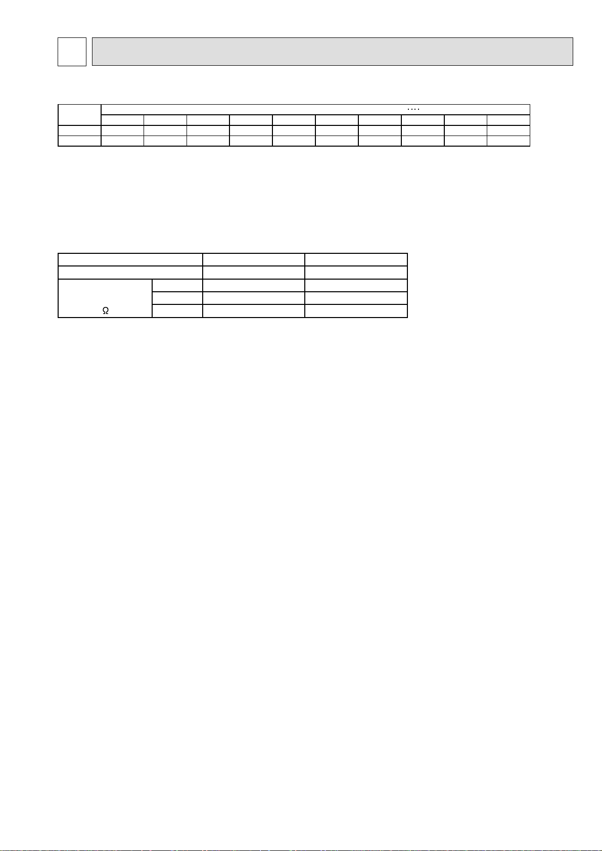
4-1. REFILLING REFRIGERANT CHARGE (R-22 : kg)
4-2. COMPRESSOR TECHNICAL DATA
at 20˚C
Note:
If there is an insufficient amount of refrigerant in the system, the unit will behave in one of the following ways: 1) the discharge temperature of the unit rises abnor-
mally high, which is detected as an error, and the unit comes to a stop; 2) the discharge temperature of the compressor rises abnormally high, the unit goes into
the unload operation, which appears as the P8 error on the display, and the unit comes to a stop; or 3) the built-in thermostat on the compressor goes off and
stops the compressor. In either case, replenish and adjust the refrigerant. Once the unit goes into the unload operation, it takes at least 3 hours until normal operation can be restored.
Model
PUH-8 0.0 0.3 0.9 1.5 2.1 2.6 3.2 3.8 4.4 5.0
PUH-10 0.0 0.3 0.9 1.5 2.1 2.6 3.2 3.8 4.4 5.0
7.5m 10m 15m 20m 25m 30m 35m 40m 45m 50m
Piping length (one way) Additional refriferant charge (R22) kg
Outdoor Unit
Compressor Model
Widing
Resistance
( )
T1-T2 1.59 1.23
T2-T3 1.59 1.23
T3-T1 1.59 1.23
PUH-8 PUH-10
ZR-94KC-TFD-501 ZR-125KC-TFD-501
Page 8
8
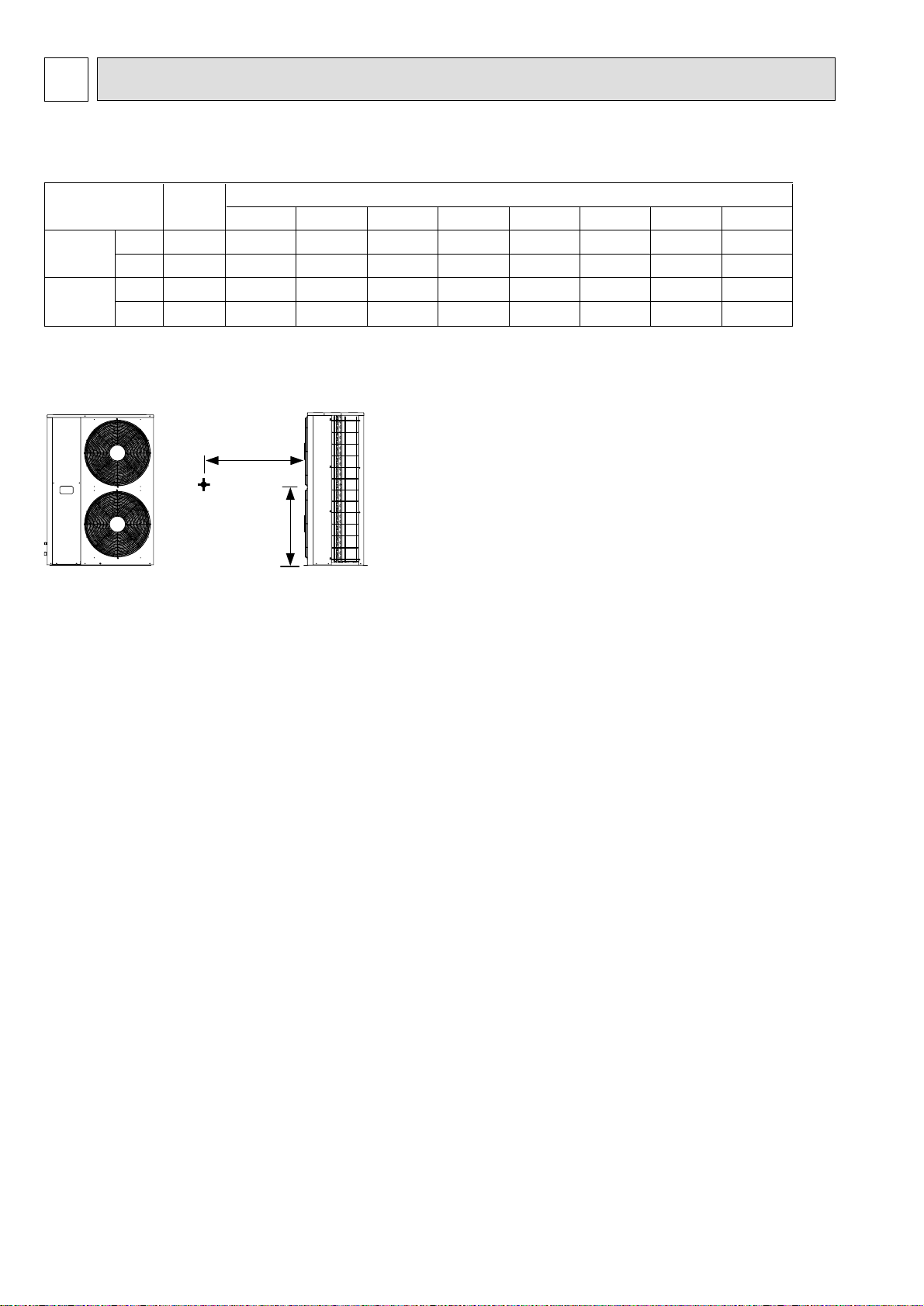
5 SOUND DATA
5-1. OUTDOOR UNITS
(2) Position measurement
SPL
dB(A) 63Hz 125Hz 250Hz 500Hz 1000Hz 2000Hz 4000Hz 8000Hz
(1) Sound Levels
PUH-8
YKA
Cool
Heat
Cool
Heat
PUH-10
YKA
61
63
61
63
60
62
59
60
59
61
59
60
58
61
59
62
59
60
59
62
57
58
57
58
54
54
53
54
48
50
49
49
42
44
42
43
Model
PUH-8,10YKA
Measurement
point
OCTAVE BAND FREQ.Hz
1m
0.75m
Page 9
9
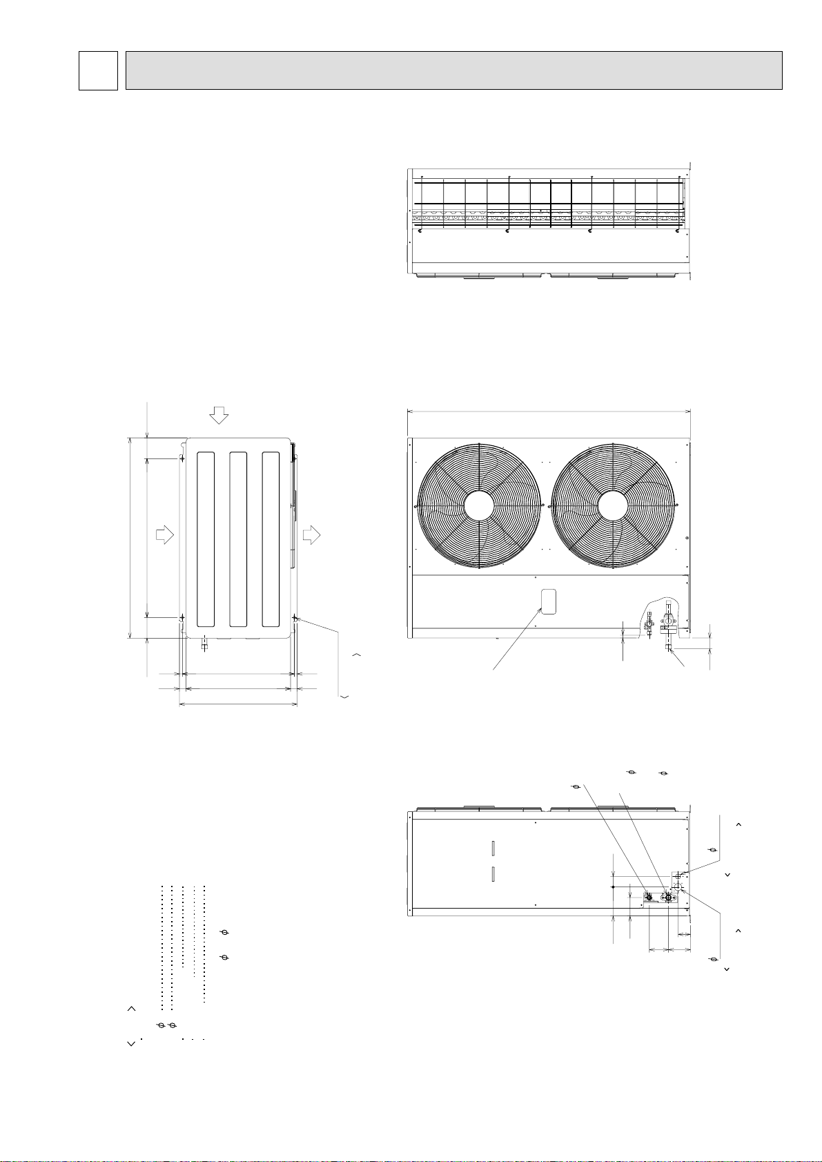
6 OUTLINES AND DIMENSIONS
PUH-8YKA, PUH-10YKA
Unit : mm
Accessory
Conduit mouting plate
(Painted the same color as the unit body)
27 1pc.
34 1pc.
Tapping screw 4X12
Connection pipe
Packing.
Note 1.It is possible to change to
selecting the conduit mounting plate a,b.
4-10X20 Holes
Refrigerant pipe
PU-8YAKD
PUH-8YKA
25.4 (1 flange)
PU-10,12YAKD
PUH-10YKA
:
Knock out hole
Pressure gauge
(For option)
Refrigerant pipe
15.88(5/8 flare)
For the indoor unit
connection wiring
27 Hole
Note 1
For the power
supply wiring
40 Hole
For mounting
anchor bolt M8
[Field supply]
Air outlet
Air
inlet
Air inlet
Top view
Right side view
Front view
Left side view
Connection pipe
(Accessory)
28.6 (1-1/8 flange)
:
27 or 34 by
4pcs.
1pc.
1pc
a)
b)
615
3454734
585 1515
1480
1047
108.5 830 108.5
15
57
97
152 55
65
115 100
Page 10
10
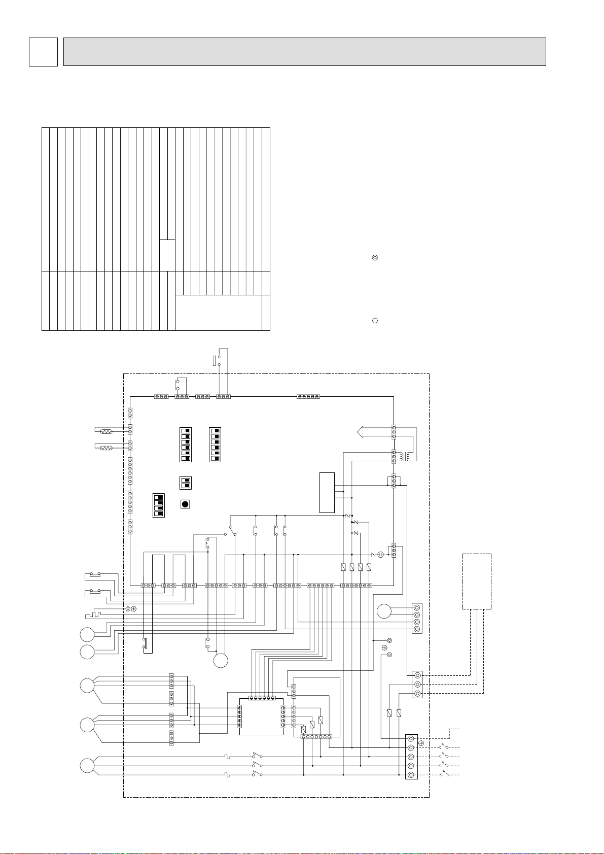
7 WIRING DIAGRAM
PUH-8YKA, PUH-10YKA
DISCHARGE TEMP
LIQUID PIPE TEMP
AUXILIARY RELAYX1TRTRANSFORMER
OVER CURRENT RELAY (COMPRESSOR)
MAGNETIC CONTACTOR (COMPRESSOR)
PRESSURE SWITCH (LOW PRESSURE)
63L
51C
52C
F1,F2 FUSE (15A 250VAC CLASS T)
SYMBOL NAME
FAN MOTOR (OUTDOOR)MF2,MF3
PRESSURE SWITCH (HIGH PRESSURE)
PRESSURE SWITCH (FOR CONTROL)
MC COMPRESSOR MOTOR
63H1
63H2
4-WAY VALVE
21S4
OUTDOOR UNIT
TH2
21 21
TH1
THERMISTOR
FUSE (6.3A 250VAC CLASS F)
SWITCH
AUXILIARY RELAY
SOLENOID VALVE
CRANK CASE HEATER (COMPRESSOR)
TERMINAL BLOCK
CH
SV1
TB1,3,8
CN3D
CN3 CN4
CN2
CN40
ON
4123
CNMNT
CNVMNT
LED (FOR SERVICE)
F01-F04
LED1
TH1
TH2
OUTDOOR
MAIN BOARD
X1
1
3
CN3S
OFF
ON
64123 5
OFF
ON
12
OFF
SW5
X01-X05
SW1-5
CN3N
SW1SW4SW3
X04
CONNECTOR (THERMISTOR FOR COND/EVA TEMP)
CONNECTOR (LEV)
CONNECTOR (CONNECT TO OPTIONAL M-NET ADAPTER BOARD)
CONNECTOR (CONNECT TO OPTIONAL M-NET ADAPTER BOARD)
CN4
CN40
CNMNT
CNVMNT
63H2
1
3
CN24
OFF
ON
64123 5
SW2
X03
CONNECTOR (EXTERNAL I/O)
CONNECTOR (NIGHT MODE/SNOW SENSOR)
CONNECTOR (OPARATION)
FUSE (6.3A 250VAC CLASS F)
CN51
CN3N
CN3D
F10-F30
N.F.BOARD
sure matching wiring and terminal.
2.Color of earth wire is yellow and green twisting.
3.Specification subject to change without notice.
4.This motor(*1) includes auto reset type internal thermostat.
5.Indoor and outdoor connecting wires (*2) are made with polarities, make
Note:1.The dotted lines show field wiring.
CN51
DC power supply
MAIN BOARD
Transmission
Circuit
X01
X02
X05
over current relays is installed. Therefore, do not
change factory set value of over current relays.
1.To protect compressor from abnormal current,
6. mark is connector. mark is terminal.
Caution,
CN34
SECONDARY
313131
TR
CN28
PRIMARY
CNS3
CNFG
31
OUTDOOR UNIT CONTROL BOX
(*1)(*1)
CH 63H1 63L
21S4
SV1
MF2 MF3
MC
Black
White
Red
CN23
1
51C
F01
F04
F03
CN22
1
3
3
135
1
3
CN26
CN21
CN25
1
CN53
CN52
3
1
CNFC1
1
3
5
6
6
52C
52C
C21C22
13
1
C11C12
13
1
1
CNFAN
135
CNFC2
F.C.
6
CNPOW
BOARD
CNOUT2
135 13
135
CNOUT1
F10
F20
F30
CNIN
7
CN20
7
L1NL2
N.F. BOARD
F02
1
L3
X1
F1
Green/Yellow
Blue
Black
IN
IN
OUT OUT
TB8
S3S2S1
TB3
F2
N
INDOOR UNIT
TO INDOOR UNIT
CONNECTING WIRES (*2)
(POLER)
PE
White
51C
Red
52C
TB1
L1 L2 L3
POWER SUPPLY
3N~PE
380/400/415V
50HZ
CIRCUIT BREAKER
PUH-8,10YKA : 50A
(FIELD SUPPLY)
Page 11
11
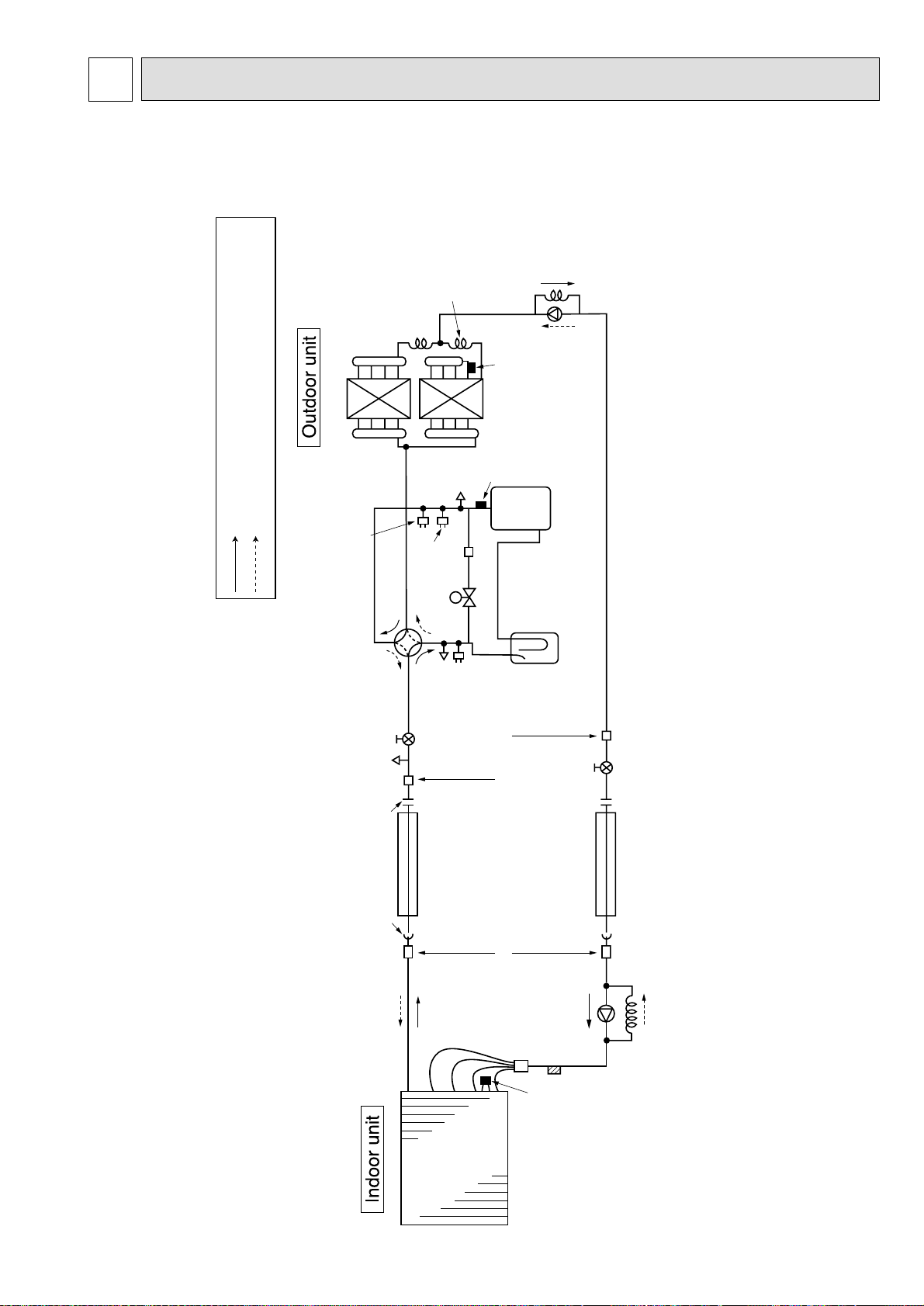
8 REFRIGERANT SYSTEM DIAGRAM
PEH-8: O.D. 4.0
×
I.D. 3.0-L1000
PEH-10: O.D. 4.0
×
I.D. 3.0-L700
PUH-8:
O.D. 6.0
×
I.D. 4.0-L14
PUH-10:
O.D. 6.0
×
I.D. 4.6-L15
Outdoor heat exchanger
Thermistor
TH1
(liquid temp)
Thermistor TH2
(discharge temp)
Low pressure
switch
(with heat insulator)
Ø15.88mm
Refrigerant pipe
Refrigerant pipe
8HP:Ø25.4
10HP:Ø28.6mm
(with heat insulator)
Ball valve
Ball
valve
Service
port
4-wau value
Service port
High pressure switch
(protection)
High pressure
switch (control)
Service
port
Strainer
Capillary
tube
Capillary tube
O.D. 6.0
×
I.D. 4.0-L800
Capillary tube
O.D. 6.0
×
I.D. 4.0-L700
Compressor
Accumulator
Solenoid valve
Strainer Strainer
Indoor
heat
exchanger
Restrictor
valve
Distributor
Thermistor
TH2
Thermistor
TH5
Capillary
tube
Flared
connection
Brazing
connection
Brazing
connection
Flange
connection
Restrictor
valve
Refrigerant flow in cooling
R.V.coil
Heating:ON
Cooling:OFF
Refrigerant flow in heating
PUH-8YKA PUH-10YKA
Page 12
12
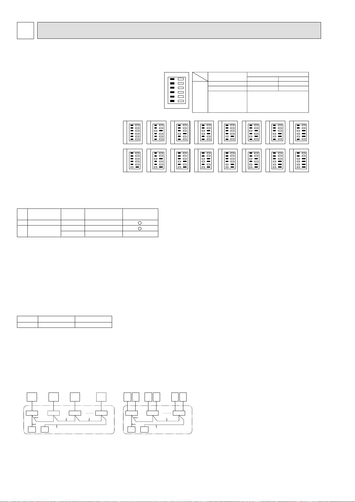
9 SYSTEM CONTROL
9-1. OUTDOOR UNIT ADDRESS SETTINGS
9-2. EXAMPLES OF REFRIGERANT SYSTEM ADDRESS SETTING
9-3. CAPACITY CONTROL SETTING METHOD (PEH-16, 20 ONLY)
9-4. GROUPING BY USING LCD REMOTE CONTROLLER
••When controlling a group, the address must be set for each outdoor unit.
During address setting, set all the dip switches SW1 (3 - 6) on the board to
<when shipped from factory: all OFF>. (Address setting is not necessary for
1:1 or Free multi-component systems.)
•
Settings using SW1 are given below.
•
Please set the mutually different address, and pre vent the start up simultaneously. (In case of connecting with PEH-16, 20)
(SW1)
OFF ON
1
2
3
4
5
6
1 –
2 Error history clear
3 Refrigerant system
address setting
4 ↑
switching
5 ↑
SW1 function
6 ↑
Model
Operation by switch manipulation
ON
––
Clear
OFF
Ordinary
Outdoor unit address
Settings 0 - 15
0
8
OFF ON
1
2
3
4
5
6
OFF ON
1
2
3
4
5
6
1
9
OFF ON
1
2
3
4
5
6
OFF ON
1
2
3
4
5
6
OFF ON
1
2
3
2
4
5
6
OFF ON
1
2
3
10
4
5
6
OFF ON
1
2
3
3
4
5
6
OFF ON
1
2
3
11
4
5
6
OFF ON
1
2
3
4
4
5
6
OFF ON
1
2
3
12
4
5
6
<Standard setting>
–
No.1
No.2
Outdoor unit refrigerant
system address
00
00
01~15
Ex.
Indoor unit
1
PEH-8, 10
2
PEH-16, 20
*
Set the refrigerant system address of one outdoor unit to 00 for the power supply
Outdoor unit
Remote controller
power supply unit
X
to the remote controller.
(The refrigerant system address is set to 00 when shipped from the factory.)
Do not duplicate the refrigerant system address settings within the same system.
OFF ON
1
2
3
5
4
5
6
OFF ON
1
2
3
13
4
5
6
OFF ON
1
2
3
6
4
5
6
OFF ON
1
2
3
14
4
5
6
OFF ON
1
2
3
7
4
5
6
OFF ON
1
2
3
15
4
5
6
With the PEH-16, 20 which has two outdoor units, the capacity can be controlled to
0%, 50% or 100%.
This is set by setting the outdoor unit side dip switches as shown in the table below
before turning the power on.
DipSW5-1
No.1 side outdoor unit
OFF
No.2 side outdoor unit
ON
Combination of indoor/outdoor unit can be controlled up to a maximum of 16 refrigerant systems.
* In case of PEH-8, 10 * In case of PEH-16, 20
FGEJ
A
AA
2
B
2 2
A
BBB
1
D
C
1
EF GH IJ
A
No.1ANo.2ANo.1ANo.2ANo.1
B BB
2
A
No.2
2
1
C D
1
C Main remote controller D Subordinate remote controller
E Standard (Refrigerant address = 00)
F Refrigerant address = 01 G Refrigerant address = 02
H Refrigerant address = 03 I Refrigerant address = 14
J
B Indoor unitA Outdoor unit
Refrigerant address = 15
Page 13
13
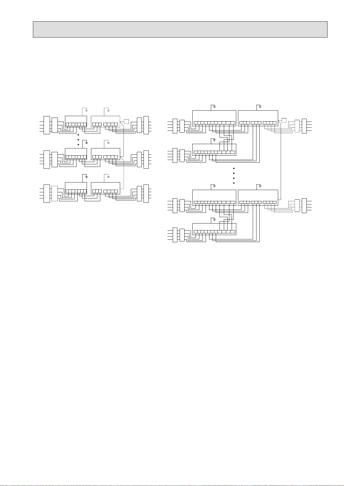
1 Wiring from the Remote Control
This wire is connected to TB5 (terminal board for remote controller) of the indoor unit (non-polar).
2 When a Different Refrigerant System Grouping is Used
Up to 16 refrigerant systems can be controlled as one group using the LCD remote
controller.
Notes:
1. In single refrigerant system, there is no need of wiring 2 .
2. LCD remote controller can be installed up to a maximum of 2 units for one group.
Grouping (16 outdoor units) [Connecting with PEH-16, 20]Grouping (16 outdoor units) [Example: PEH-8, 10]
PUH-8, 10
(00)
L1 L2 L3 N S1 S2 S3
PUH-8, 10
(01)
F
L1 L2 L3 N S1 S2 S3
PUH-8, 10
L1 L2 L3 N S1 S2 S3
PUH-8, 10
(15)
F
L1 L2 L3 N S1 S2 S3
(14)
OUT OUT
OUT OUT
OUT OUT
OUT OUT
IN IN
IN IN
IN IN
IN IN
B
A
A B C
A B C
C
PUH-8, 10
(00)
F
L1 L2 L3 N S2S1 S3S2S1 S3
PUH-8, 10
(14)
L1 L2 L3 N S2S1
PUH-8, 10
(15)
L1 L2 L3 N S2S1
PEH-8, 10
E
L1 L2 L3 N
PEH-8, 10
EF
L1 L2 L3 N
S3S2S1 S3
PEH-8, 10
EF
S3S2S1 S3
L1 L2 L3 N
D
B
C
A
A BC
A B C
A B C
A BC
A B C
A B C
A Power supply B Earth leakage breaker C Circuit breaker or local switch D Remote controller E Indoor unit F Outdoor unit (Address)
PEH-16, 20
EF
(TB4-1) (TB4-2)
S1 S2 S3 S1 S2 S3 L1 L2 L3 N
PEH-16, 20
EF
(TB4-1) (TB4-2)
S1 S2 S3 S1 S2 S3 L1 L2 L3 N
D
A BC
A BC
Page 14
14
10 TEST RUN
10-1. OUTDOOR UNIT
(1) Test run
The test run can be carried out from the outdoor unit.
1. Checklist
• After the installation, piping setup, and wiring of the indoor and outdoor units is
complete, check that refrigerant is not leaking, the power and control wires are
not loose, and the poles are not reversed.
• Use a 500 V insulation resistance tester to make sure that the resistance be-
tween the power terminal and the ground is 1.0 MΩ or more. If it is less than
1.0 MΩ, do not operate the unit. * Absolutely do not touch the tester to indoor/
outdoor connection terminals S1, S2, and S3. An accident could occur.
• Make sure there is no malfunction in the outdoor unit. (If there is a malfunction,
you can diagnose it using LED1 on the board.)
• Check that the ball valve is fully open on both the liquid and gas ends.
• Check to make sure that L
order. Connecting them in the reverse order will trip the negative-phase protector, and the unit will come to a stop, displaying the Error code F1.
• •Starting at least 12 hours before the test run, send current through the
crankcase heater. (If the current is running for a shorter period of time,
damage to the compressor could result.)
After the above checks are complete, carry out the test run as indicated in the
following outline.
1, L2, and L3 are connected in the correct phase
2. Starting and finishing the test run
• Procedure from the outdoor unit: start and stop the test run and set test run
mode (cooling/heating) using the SW4 dip switches on the board.
1 Set test run mode (cooling/heating) using SW 4-2.
2 The test run will begin when SW 4-1 is turned ON, according to the mode
selected by SW 4-2.
3 The test run is stopped when SW 4-1 is turned OFF.
<SW4>
OFF
ON
stop
1
2
cooling
Note:
Test run mode cannot be stopped during operation by using SW 4-2. (If the
operation mode is to be changed, first stop it using SW 4-1, then after c hanging the operation mode, start the test run again using SW 4-1.)
• If the 2-hour timer is set, the test run will stop automatically after 2 hours.
• During the test run, the room temperature display on the indoor unit will indi-
cate the temperature of the indoor unit piping.
• When you operate the test run from OC1, all trial runs are completed by OC1
→ IC1 → MA → IC1 → OC2.
PEH-16, 20(IC1) MA
OC1
OC2
run
heating
(2) How to handle problems with the test run
Error code list:
Remote controller
display
E0
E1, E2
E3
E4
E5
E6
E7
E8
E9
EA
EB
EC
ED
EE
F1
F8
A0
A2
A3
A6
A7
A8
EF
U2
U2
U3
U4
U6
UE
UL
F8
P1
P2
P4
P5
P5
P6
P6
P8
P9
details
MELANS display
6831,6834
6201,6202
6832,6833
6831,6834
6832,6833
6740,6843
6841,6842
6840,6843
6841,6842
6844
6845
6846
0403
0403
4103
4115
6600
6602
6603
6606
6607
6608
undefined
1102
1108
5104
5105
4101
1302
1300
4115
5101
5102
2503
2502
2500
1503
1504
1110
5103
Remote controller communication – reception error
Remote controller board error
Remote controller communication – transmission error
Remote controller communication – reception error
Remote controller communication – transmission error
Communication between indoor and outdoor units – reception error
Communication between indoor and outdoor units – transmission error
Communication between indoor and outdoor units – reception error
Communication between indoor and outdoor units – transmission error
Indoor/outdoor connection wiring error, indoor unit overload (5 units or more)
Indoor/outdoor connection wiring error (interference, loose)
Excessive time in use
Serial communication error
Serial communication error
Reverse phase, out of phase verification
Faulty input circuit
Duplicated M-NET address setting
M-NET error in PH/W transmission
M-NET bus busy
M-NET communication error with P transmission
M-NET error – no ACK
M-NET error- no response
Undefined error code
Outlet temperature error
CN23 Short-circuit Connector Unplugged
Open/short in discharge temp thermistor
Open/short in liquid temp thermistor
Compressor overcurrent interruption (51C operation)
High pressure error (63H1 operation)
Low pressure error (63L operation)
Power synchronous idle circuit error
Inlet sensor error
Open/short in liquid temp thermistor
Drain sensor error
Drain overflow protector operation
Water leak error (PDH only)
Freeze prevention operation
Surge prevention operation
Piping temperature error
Open/short in condenser/evaporater temp thermistor
Error details
Problem location
Remote Controller
Remote Controller
Remote Controller
Indoor unit
Indoor unit
Indoor unit
Indoor unit
Outdoor unit
Outdoor unit
Outdoor unit
Outdoor unit
Outdoor unit
Outdoor unit
M-NET board
Outdoor unit
Outdoor unit
M-NET board
M-NET board
M-NET board
M-NET board
M-NET board
M-NET board
–
Outdoor unit
Outdoor unit
Outdoor unit
Outdoor unit
Outdoor unit
Outdoor unit
Outdoor unit
Outdoor unit
Indoor unit
Indoor unit
Indoor unit
Indoor unit
Indoor unit
Indoor unit
Indoor unit
Indoor unit
Indoor unit
Page 15
15
• Depending on the position of the SW2 switch on the outdoor unit board, the segments light up to indicate the running condition of the unit and the particulars of the chec
k
code.
SW2 setting
123456
000000
Operation mode/relay output
Item
tens place O: stop
C: cooling
H: heating
d: defrosting
units place 1: SV1
2: 21S4
4: 52C
When an error occurs, the error code
and error signal (*1) are displayed in
alternation.
Display contents
Relay output = SV1 + 21S4 + 52C
Ex. During cooling mode, when 52C and SV1 are ON: C5
011110
010110
110110
011100
111100
*1 Display system for error indicator
The indicator corresponds to the following numbers
0 ............. Outdoor unit
1 ............. Indoor unit No.1
2 ............. Indoor unit No.2
3 ............. Indoor unit No.3
4 ............. Indoor unit No.4
Outdoor unit control condition
Indoor unit control condition
Indoor unit control condition
Error code history 1
Error code history 2
(IC1)
(IC2)
(IC3)
(IC4)
Control mode display system
Indoor unit No.2
Indoor unit No.4
The error code (ex. U8, UA) and error indicator (*1) are displayed in alternation.
Indoor unit No.1
Indoor unit No.3
Outdoor unit
Display
0
1
2
3
4
5
6
7
Hot adjustment
Freeze prevention
Surge prevention
Compressor OFF
Control mode
Indoor unit
Ordinary
Defrosting
—
Heater ON
Outdoor unit
←
←
←
←
←
←
←
←
Page 16

16
11 CONTROL
11-1. COMPOSITION OF CONTROL
(1) Function block diagram
3N~
380/400/415 V
50 Hz
outdoor
indoor
Electrical
terminal block
Indoor/outdoor
connection terminal
Indoor/outdoor
connection terminal
block
block
Fuse
Fuse
Fuse
T
microcomputer
Communication
circuit
DC/DC
converter
LED1
<Power>
ransformer
DC5V for
12V
Magnetic
contractor
Fuse
Semiconductor
relay
Fan control
Over current
relay
4-way valve,
solenoid valve,
crankcase heater
Outdoor fan
Semiconductor
relay
Compressor
Louver
Vane
Drain pump
Others
Remote
controller
terminal block
Remote controller
terminal block
Remote controller
Current
detection
LED2 LED3
<Supply power>
DC5V
5V
<Indoor/outdoor units communication>
Key input
LCD
Send/receive
Communication
circuit
Fan control
Indoor fan
Page 17

17
11-2. CONTROL SPECIFICATIONS
(1) Protection functions
1) The main protection devices for the outdoor unit are:
a) High pressure protection (63H1)
b) Compressor overcurrent protection (51C)
c) Liquid temp thermistor trouble (TH1)
d) Discharge temperature protection (TH2 ≥118 °C)
e) Discharge temp thermistor trouble (TH2)
f) Low pressure protection (63L)
2) When tripping of a detection device is sensed, the check mode is entered and the compressor is stopped. (After 3
minutes, the compressor restarts.) Thereafter, the compressor is stopped when the specified number of check
modes or greater is sensed within the check time.
Protection functions
a) High pressure protection
(63H1)
b) Compressor
protection (51C)
Compressor internal
thermostat
Outdoor unitIndoor unit
d) Liquid temp thermistor
trouble (TH1)
e) Discharge temperature
protection (TH2
f) Discharge temp ther-
mistor trouble (TH2)
g)
Low pressure protection
(63L)
overcurrent
>
135 °C)
=
Operation value
3.3 MPa
PUH-8:22A
PUH-10:28A
PUH-8:130 ± 5˚C
80A in 3-10sec
PUH-10:105 ± 5˚C
95A in 3-10sec
Less c)than –39 °C or
greater than 88 °C
Greater than 135 °C
Less than 0 °C or
greater than 216 °C
0 MPa
Detection condition
Compressor operating
Compressor operating
Compressor operating 0 –
Compressor operating except for
10 minutes at end of defrosting
and 7 minutes while compressor
starting
Compressor operating
Compressor operating except for
10 minutes at end of defrosting
and 5 minutes while compressor
starting
Compressor operating except for
defrosting, 10 minutes at end of
defrosting
Number of
check modes
0
1 time
1 time
2 times
1 time
2 times
Check time
30 minutes
30 minutes
30 minutes
30 minutes
30 minutes
–
h)
Intake temp thermistor
(TH1)
Liquid temp thermistor
i)
(TH2)
TH1 -39˚C
88˚C TH1
TH2 -39˚C
88˚C TH2
Compressor operating except for
3 minutes after the detection of
preliminary inlet temperature
sensor error
Compressor operationg except
for 7 minutes while compressor
starting and for 3 minutes after
the detection of preliminary pipe
temperature sensor error
2 times
2 times
30 minutes
30 minutes
Page 18

18
3) Check mode is released by stopping operation, changing the operation mode, or check mode time up. A check
mode is also released by stopping of operation by remote controller.
4) Detected check mode history (newest) and abnormality history (last 2 times) are memorized and are displayed on
the segment by circuit board DIP switch setting.
The operation mode when the newest abnormality was generated, the thermistor temperature (TH1,2), and the
thermostat ON time can also be displayed.
(2) Compressor, 4-way valve, and crankcase heater control
1) Determines the operation mode and operates the compressor based on the indoor/outdoor communication or MNET communication data.
2) Compressor control has a function which prevents the compressor from restarting within 3 minutes.
3) The 4-way valve is always ON during heating (except during defrosting). In other modes, it is OFF. However, when
the operation mode was changed from heating to stop, the 4-way valve is turned off 10 minutes after the compressor was stopped.
4) While the compressor is stopped, the crankcase heater remains ON. (OFF while the compressor is operating.)
5) When the operation mode is changed while the compressor is operating, the compressor stops and 3 minutes later
restarts in the new mode.
(3) Fan control
Controls the fan speed based on the piping temperature (TH1) to perform cooling at low outdoor temperatures and heating
at high outdoor temperatures.
1) Control at cooling
a) When the compressor stops, the fan stops (fan output=0%).
b) When the power is turned on, or when the compressor is restated after it has been stopped for 30 minutes or
longer, the piping temperature ( TH1) determines the fan output.
When TH
When TH < 25˚C Fan output = 60 %
c) When the compressor is restarted within 30 minutes after it has been stopped, the f an step before the compres-
sor was stopped is selected. Howev er, when the fan output was under 30% when the fan was stopped, 30% is
selected.
d) When the mode was changed from heating to cooling, the fan step conforms to item 2.
e) Two minutes after the fan is started, the fan step (number of units) is controlled every 30 seconds based on the
piping temperature (TH1).
f) When TH1 reaches 55˚C or higher, or when the control high pressure switch (63H2) tr ipped, the fan output
becomes 100%.
g) Fan output while the compressor is operating is within the 20% to 100% range.
• FAN step
The following expression determines the next fan step count nj+1:
nj + 1 = nj + ∆nj nj: Current fan step, ∆nj: Displacement step amount
nj control
• If nj + 1 ≥ 100% nj + 1 = 100%
• If nj + 1 20% nj + 1 = 20%
• If TH1 ≥ 55 °C or 63H2 is “OFF” nj + 1=100%
25˚C Fan output = 100 %
FAN ∆nj Outputs are all %.
20 ˚C
Target condensation
temperature 31 °C
20 ≤ nj < 50
50 ≤ nj < 100
Current
output
t > 49 °C
5
10
t = 49
t = 46
~
t > 46
t > 43
3
4
* In the night mode, the maximum value of nj is 80%. (When TH1 55˚C)
Condensation temperature TH1
t = 43
t = 40
~
~
t > 40
2
2
3
2
~
t > 36
2
2
t = 36
~
t > 33
2
2
t = 33
~
t > 29
0
0
t = 29
~
t > 26
–2
–2
t = 26
~
t > 23
–2
–2
t = 23
~
t > 20
–3
–4
t
≤
–5
–10
Page 19

19
2) Control at heating
a) When the compressor is stopped and during defrosting, the fan is stopped.
b) When the power is turned on, or when the compressor is restarted after being stopped for 30 minutes or longer,
the piping temperature (TH1) determines the fan step.
TH1 8˚C Fan output = 60%
< 8˚C Fan output = 100%
TH1
c) When the compressor is restarted within 30 min utes, the fan step is the step before the compressor was stopped.
d) When the mode is changed from cooling to heating, the fan step conforms to item b).
e) When returning from defrosting, the fan step is the step before defrosting.
f) Two minutes after the fan was restarted, the fan step is controlled every 30 seconds based on the piping
temperature (TH1).
g) When TH1 is –5˚C or lower, the fan output is made 100%.
• FAN step
The following expression determines the next fan step count nj + 1:
nj + 1 = nj + ∆nj nj: Current fan step, ∆nj: Displacement step amount
nj control
• If nj + 1 100% nj + 1 = 100%
• If nj + 1 ≤ 20% nj + 1 = 20%
• If TH1 < –5 °C nj + 1=100%
FAN ∆nj Outputs are all %.
Evaporation temperature TH1
Target evaporation
temperature 10 °C
T > 19 °C
T = 19
~
T > 17
T = 17
~
T > 15
T = 15
~
T > 13
T = 13
~
T > 11
T = 11
~
T > 8
T = 8
~
T > 6
T = 6
~
T > 4
T = 4
~
T > 2
T = 2
~
T > 0
T≤ 0˚C
20 ≤ nj + 1 ≤ 100
Current
output
–10
–4
–3
–2
–2
0
2
2
3
4
(4) Defrosting control
1) When the following conditions are satisfied, defrosting starts:
a) When the integrated compressor operation time has exceeded T
temperature (TH1) is below –5˚C
b) When the integrated compressor ˚C
Piping differential temperature ∆TH1 = TH10 – TH1
Piping temperature 10 minutes after starting or
10 minutes after returning from defrosting
2) The defrosting prohibit time T
2 ≤ 3 (minutes) T1 60 (minutes)
T
2 740
3 < T
7< T
2 10 40
10 < < T
2 15 40
= 15
T
2
1 is set as following based on the defrosting time T2:
30
1 is reset at the end of defrosting, or by cooling ON command.
Note: T
Note: When the compressor was stopped during defrosting, T1 = 20 minutes is set to recognize the stop as
defrosting end.
3) During defrosting, all the outdoor f ans are stopped and the bypass solenoid valv e (SV1) is turned ON and the 4-way
valve (21S4) is turned OFF.
4) When the following conditions are satisfied, defrosting ends:
a) T
b) 5 <
c) T
5) When
2 ≤ 5 mins TH1 ≤ 25°C
3<
T
2 < 15 minutes TH1 ≤ 20°C continuous 2 minutes
2 =15 minutes
the fan and 4-way valve (21S4) are turned ON at the end of defrosting, the heating mode is reset.
minutes after defrosting reset, the bypass solenoid valve (SV1) turns OFF.
6) When using PEH-16·20MYC, alternate defrosting is possible after sending and receiving each respective
outdoor unit defrost signal.
1 (initial setting 40 minutes) and the piping
Current piping temperature
10
Two
Page 20

20
(5) Bypass solenoid valve control (SV1)
1) Control at cooling
a) While the compressor is stopped, the solenoid valve is OFF.
b) When the power is turned on, or when the compressor is restarted after it has been stopped for 30 minutes or
longer, if the liquid temperature (TH1) is 25˚C or higher then the solenoid valve turns ON for 2 minutes.
c) When the power is turned on, or when the compressor restarted after it has been stopped for 30 minutes or
longer, the solenoid valve turns ON for 5 minutes if the liquid temperature (TH1) is staying below 25˚C.
d) The item b) or c) is applied to the mode change from heating to cooling.
e) When the pre vious operation mode is cooling and the compressor restarted within 30 minutes after it’s stopping
by the tripping of 63H2, the solenoid valve turns ON for 2 minutes.
2) Control at heating
a) While the compressor is stopped, the solenoid valve is OFF.
b) When the power is turned on, or when the compressor restarted after it has been stopped for 30 minutes or
longer, the solenoid valve turns ON for 2 minutes if the liquid temperature (TH1) is staying above 8˚C.
c) When the power is turned on, or when the compressor restarted after it has been stopped for 30 minutes or
longer, the solenoid valve turns ON for 5 minutes if the liquid temperature (TH1) is staying below 8˚C.
d) The item b) or c) is applied to the mode change from cooling to heating.
e) When the control pressure switch (63H2) trips, the solenoid valve turns ON.
f) If 63H2 resets 15 minutes after tripping, the solenoid valve turns OFF.
g) During defrosting, the solenoid valve turns ON.
h) When the pre vious operation mode is heating and the compressor restarted within 30 minutes after it’s stopping
by the tripping of 63H2, the solenoid valve turns ON for 2 minutes.
i) When the previous operation mode is heating, and the compressor restarted within 30 minutes after the tripping
of 63L, the solenoid valve turns ON for 2 minutes.
(6) Service functions
1) Abnormality history clear
a) When DIP SW1-2 is turned ON while the compressor is operating or stopped, the abnormality history is cleared.
Page 21

21
11-3. FUNCTION OF SWITCHES AND CONNECTORS (OUTDOOR UNIT)
(1) Outdoor unit
OFF
N
5
N
356
N
356
N
6
OFF
5
OFF
ON
OFF
ON
356
OFF
ON
356ON365
568
9
3
)
es
on
of
es
)
h
en
n
)
2
3
4
5
ec-
g
d
r
ed
d
d
d
r
ed
r
ed
n
F
r
3.
r
al
e
eat
oDonot
otDo
y
a
de
d
ch
eFunc
n
e
ear
m
ess
g
s
r
un
g
g
cetec
n
g
e
a
s
on
g
e
g
e
ec-
e
g
d
d
h
en
ed
e
g)
n
F
ed
g
d
ch
e
)
_
essnd
e
de
o
ge
g
.
33
33.
0
us
es
us
es
de
*
,
.
e
e
e
1)Functi
a
Normal mode
Kin
wit
witc
Wh
ope
Normal
witch
witch
Pol
Abnormalityhistoryl
Refrigerant syste
r
Non
tio
settin
Norm
lmo
W3=
Operation
witch operatio
lea
O
123456
ON
O
OFF
0123
ON
OFF
123456
O
OFF
ON
OFF
123456
OFF
OFF
O
ON
123456
3,4
W1
reN
F
OFF
12
ON
OFF
1
witch
tivetimin
Running
stoppe
henpowe
turn
f
W
act
W
W
W
b)witch functionst
Kin
wit
witc
Pol
Wh
hort
od
witchin
*
rialrun trail run byinput stopped.
rk
*
Modeinput
m
mo
Note:
After themodebyN
n
Factory settin
elf diagnosi
Mode input registe
r
rialrun mode switchin
Inlet temp. re-readin
3-phase power
our
tio
Coolingonlyswitchin
Non
tmodechan
Functi
Non
Non
Non
Defrostingndswitchin
Defrostingprohibit tim
switchin
Non
W3
t
continuous 2 minutes
ee pages 109 to 11
Registe
Operat
H
Norm
Stop
ool
D
Do n
Coolingonl
et input
N33=
hort
Operation
o
W3=
witch operatio
Heat pump
N
F
2
ontinuo
t
Fix
For
Pr
t
own
ontinuo
rainin
W3for
thetrail run section
out
onds.Th
mode switching), return tothenormalmodebyopeningN
Running
stoppe
stoppe
stopped*
stoppe
henpowe
turn
henpowe
turn
witch
timin
tiv
stoppe
stoppe
f
Page 22

22
c) Connector function assignment
Type
Connector
CN31
CN32
CN33
Function
Emergency operation
Function test
DIP switch mode switching
Operation by open/short
short open
Start Normal
Function mode Normal
Mode switching Normal
Switch effec-
tive timing
At initialization
At initialization
stopped
CN3N-3 Snow sensor Snow sensor control Normal Always
Connector
CN3N-2 Night mode Night mode Normal Always
CN3D-2 Switch cooling/heating Heating Cooling Always
CN3D-3 Auto switching contact Switch cooling/heating Normal Always
CN3S-2 Contact demand Contact demand Normal Always
CN3S-3 Alternating defrost
Defrost signal from other unit
Normal Always
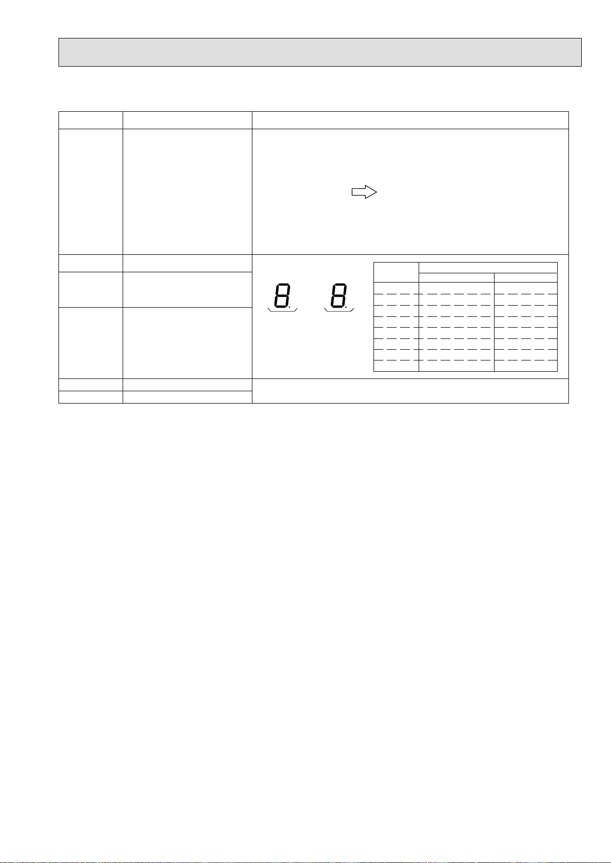
2) Outdoor unit operation monitoring function
The operation status and check code contents can be ascertained by means of the 2-digit number and symbol on digital
display light emitting diode LED2 by operating DIP switch SW2.
<Description of operation of digital display light emitting diode (LED2)>
• When ON (normal operation): Displays the operation mode.
SW2
123456
ON
OFF
(Load status)
LED2
[Tens digit: Operation mode]
Display Operation mode
O stopped
C Cooling/Dry
H Heating
d Defrost
ON
[Units digit: Relay output]
Display Compressor 4-way valve Bypass solenoid valve
0 –– –
1 –– ON
2 – ON –
3 – ON ON
4ON ––
5ON – ON
6ON ON –
7ON ON ON
• When blinking (Operation stopped by tripping protection device): Displays the check mode
Display Check unit
0 Outdoor unit
1 Indoor unit 1
2 Indoor unit 2
3 Indoor unit 3
4 Indoor unit 4
Display Check contents (at power on)
E8 Indoor-outdoor communication receive abnormal (outdoor unit)
E9 Indoor-outdoor communication send abnormal (outdoor unit)
EA
Eb
Indoor/outdoor connection erroneous wiring, number of indoor
units mismatch
Indoor/outdoor connection erroneous wiring (indoor unit power
failure, disconnection)
Ed Serial communication abnormal (M-NET)
E0-E7 Communication other than outdoor unit abnormal
F8 Input circuit faulty
Page 23

23
• PUH-8,10
Display Check contents (operating)
U2 Compressor discharge temperature abnormal, CN23 short-circuit connector unplugged
U3 Compressor discharge temp thermistor (TH2) open/short
U4 Liquid temp thermistor (TH1) open/short
U6 Compressor overcurrent protection trip (51C trip)
UE High pressure protection (63H1 trip)
UL Low pressure protection (63L trip)
P1-P9 Indoor unit abnormal
A0-A8 M-NET communication abnormal
Page 24

24
Self diagnosis by SW2
3)
• PUH-8,10
SW2 setting Display contents Description of display Unit
–39 - 88
(When 0 °C or lower, “–”and temperature are displayed
alternately.)
<Example> When –10,
123456
ON
OFF
Liquid temperature
(TH1)
–39 - 88
every other second
–
←→ 10
°C
123456
ON
OFF
123456
ON
OFF
123456
ON
OFF
123456
ON
OFF
Discharge temperature (TH2)
0 - 216
FAN output
0 - 100
Number of compressor
ON/OFF
0 - 999
Compressor integrated operation time
0 - 999
0 - 216
(When 100 or higher, 100s digit and 10s and units digits
are displayed alternately.)
<Example> When 115,
every other second
1
←→ 15
0 - 100
(When 100 or higher, 100s digit and 10s and units digits
are displayed alternately.)
<Example> When 100,
every other second
1
←→ 00
0 - 999
(When 100 or higher, 100s digit and 10s and units digits
are displayed alternately.)
<Example> When 425,
every other second
4
←→ 25
0 - 999
(When 100 or higher, 100s digit and 10s and units digits
are displayed alternately.)
<Example> When 245,
every other second
2
←→ 45
°C
%
100 times
10 hours
123456
ON
OFF
123456
ON
OFF
Current check mode
code 1
Current check mode
code 2
Check mode segment display
method
Segment and bit correspondence
bit 2 bit 3
bit 1
bit 5
bit 6 bit 7
bit 4
bit 8
Check mode 1 display method
bit 1..... Compressor discharge temperature
abnormal
bit 2..... Compressor discharge temp thermistor
abnormal (TH2)
bit 3..... CN23 short-circuit connector un-
plugged
bit 5..... Liquid temp thermistor abnormal (TH1)
Check mode 2 display method
bit 1..... Overcurrent trip (Comp)
bit 2..... Low pressure protection
Page 25

25
SW2 setting Display contents
Newest check code
123456
ON
OFF
Newest outdoor unit
abnormality
Check display
Description of display
When no check mode,“00”
<Example> When piping thermistor abnormal U4
Unit
Code display
123456
ON
OFF
123456
ON
OFF
123456
ON
OFF
123456
ON
OFF
Operation mode when
abnormality occurred
Liquid temperature
(TH1) when abnormality occurred
– 39 - 88
COMP discharge
temperature (TH2)
when abnormality
occurred
0 - 216
Check code history (1)
(newest)
Abnormal unit No. and
check code inverted
display
Operation mode when abnormally stopped
<Example> Comp. only ON at cooling operation C4
–39 - 88
(When 0 °C or lower, “–” and temperature are displayed
alternately.)
<Example> When –15,
every other second
–
←→ 15
0 - 216
(When 100 or higher, 100s digit and 10s and units digits
are displayed alternately.)
<Example> When 130,
every other second
1
←→ 30
When no abnormality history
“0”, “←→”, “–”
Code display
°C
°C
Code display
123456
ON
OFF
123456
ON
OFF
123456
ON
OFF
Check code history (2)
(One before newest)
Abnormal unit No. and
check code inverted
display
Current thermostat
ON time
0 - 999
Number of indoor
units connected
0 - 4
When no abnormality history
“0”, “←→”, “–”
0 - 999
(When 100 or higher, 100s digit and 10s and units digits
are displayed alternately.)
<Example> When 245,
every other second
2
←→ 45
0 - 4
Code display
Minutes
Units
Page 26

26
SW2 setting Display contents Description of display Unit
123456
ON
OFF
Outdoor unit set
information
Outdoor unit set information 1 Function setting (display valves)
3-phase power source detection Do (1) Do not (0)
ens digitUnits digit
Cooling only switching Cooling only (2) H/P (0)
T
Night mode Night mode (1) Normal mode (0)
Defrosting end time
Defrosting prohibit time Fixed (4) Training (0)
Set information display values are added and displayed at each position.
20 °C continuous 2 minutes
(2)
8 °C continuous 2 minutes
(0)
Code display
123456
ON
OFF
123456
ON
OFF
123456
ON
OFF
123456
ON
OFF
Indoor unit piping
temperature (TH2)
Indoor 1
–39 - 88
Indoor unit piping
temperature (TH2)
Indoor 2
–39 - 88
Indoor unit piping
temperature (TH2)
Indoor 3
–39 - 88
Indoor unit piping
temperature (TH2)
Indoor 4
–39 - 88
–39 - 88
(When 0 °C or lower, “–”and temperature are displayed
alternately.)
When there are no indoor units, “00” is displayed.
–39 - 88
(When 0 °C or lower, “–”and temperature are displayed
alternately.)
When there are no indoor units, “00” is displayed.
–39 - 88
(When 0 °C or lower, “–”and temperature are displayed
alternately.)
When there are no indoor units, “00” is displayed.
–39 - 88
(When 0 °C or lower, “–”and temperature are displayed
alternately.)
When there are no indoor units, “00” is displayed.
°C
°C
°C
°C
123456
ON
OFF
123456
ON
OFF
Indoor intake temperature
8 - 39.5
Indoor set temperature
17 - 30
8 - 39.5
When there are no indoor units, “00” is displayed.
°C
17 - 30
When there are no indoor units, “00” is displayed.
°C
Page 27

27
SW2 setting Display contents Description of display Unit
Indoor unit control
Control mode display system
status
123456
ON
OFF
123456
ON
OFF
Indoor 1, 2
Indoor unit control
status
Indoor 3, 4
Indoor unit No.2
Indoor unit No.4
Indoor unit No.1
Indoor unit No.3
Display
0
1
2
3
4
Freeze prevention
5
6
7
Control mode
Indoor unit
Ordinary
Hot adjustment
Defrosting
—
Heater ON
Surge prevention
Compressor OFF
Outdoor unit
←
←
←
←
←
←
←
←
–
–
123456
ON
OFF
123456
ON
OFF
123456
ON
OFF
Outdoor unit control
status
Communication demand capacity
0 - 255
Abnormal thermistor
display
1, 2, –
Control mode display system
Indoor unit No.2
Indoor unit No.4
Indoor unit No.1
Indoor unit No.3 Outdoor unit
Display
0
1
2
3
4
5
6
7
Freeze prevention
Control mode
Indoor unit
Ordinary
Hot adjustment
Defrosting
—
Heater ON
Surge prevention
Compressor OFF
Outdoor unit
←
←
←
←
←
←
←
←
0 - 255
When communication demand not set: 100%
(When 100 or higher, 100s digit and 10s and units digits
are displayed alternately.)
<Example> When 100,
every other second
1
←→ 100
1, 2, –
1: Outdoor liquid temp thermistor (TH1)
2: Outdoor discharge temp thermistor (TH2)
–: No abnor mal thermistor
–
%
–
123456
ON
OFF
123456
ON
OFF
FAN output at abnormal stop
0 - 100
Outdoor Condenser/
evaporater temp temperature at abnormal
stop
–39 - 88
0 - 100
(When 100 or higher, 100s digit and 10s and units digits
are displayed alternately.)
<Example> When 100,
every other second
–
←→ 00
–39 - 88
(When 0 °C or lower, “–”and temperature are displayed
alternately.)
<Example> When –10,
every other second
–
←→ –10
%
°C
Page 28

28
SW2 setting Display contents
Thermostat ON time up
123456
ON
OFF
to abnormal stop
0 - 999
Description of display
0 - 999
(When 100 or higher, 100s digit and 10s and units digits
are displayed alternately.)
<Example> When 245,
every other second
2
←→ 45
Unit
Minutes
123456
ON
OFF
123456
ON
OFF
123456
ON
OFF
123456
ON
OFF
Indoor unit condenser/
evaporater temp temperature (TH3)
Indoor 1
–39 - 88
Indoor unit condenser/
evaporater temp temperature (TH3)
Indoor 2
–39 - 88
Indoor unit condenser/
evaporater temp temperature (TH3)
Indoor 3
–39 - 88
Indoor unit condenser/
evaporater temp temperature (TH3)
Indoor 4
–39 - 88
–39 - 88
(When 0 ˚C or lower, “–”and temperature are displayed
alternately.)
When there are no indoor units, “00” is displayed.
–39 - 88
(When 0 ˚C or lower, “–”and temperature are displayed
alternately.)
When there are no indoor units, “00” is displayed.
–39 - 88
(When 0 ˚C or lower, “–”and temperature are displayed
alternately.)
When there are no indoor units, “00” is displayed.
–39 - 88
(When 0 ˚C or lower, “–”and temperature are displayed
alternately.)
When there are no indoor units, “00” is displayed.
˚C
˚C
˚C
˚C
Page 29

29
12 GROUP CONTROL
(1) Notes on performing group control
(
• Up to 16 indoor units can be sequentially started up with each remote controller.
• The ON/OFF control of the room temperature is performed individually for each refrigerant system with the inlet
thermistor that is built-in on the unit.
• Up to two remote controllers can be connected to each group.
(Up to two wired remote controllers can be connected. There are no restrictions on the number of wireless controllers
that can be connected.)
<System diagram>
Outdoor unit 00 Outdoor unit 01 Outdoor unit 02 Outdoor unit 15
Main
Outdoor unit
00-1
Deluxe remote controller
Indoor unit No. (Refrigerant address)
Indoor unit No. (Unit No.)
Power supply to the remote
controller (main indoor unit)
01-1
Sub
Outdoor unit
00
01102
1
02-1
1
Sub
Outdoor unit
15-1
15
1
Sub
Outdoor unit
Switch setting
Automatic setting
Automatic setting
<Wiring and setting procedures>
1 Connect the remote controller to an indoor unit, and daisy-chain all indoor units.
When connecting two remote controllers, the two controllers cannot be daisy-chained. Make the connections
through indoor units.
2 Make the refrigerant address setting for each indoor unit, and turn on the power.
Set the refrigerant address before turning on the power.
*The remote controller power supply unit is automatically set to the indoor unit with the refrigerant address of 01.
(LED 2 comes on.)
<Refrigerant address setting method>
Refrigerant addresses are also used by the sequential start up timer (4 second interval) to prevent rush current.
If any of the indoor unit addresses overlap, correct indoor unit cannot be identified during self-diagnosis or function
selection. Assign a different refrigerant address to all indoor units, following the setting procedures below.
<Refrigerant address setting with SW1 (No.3-6) on the Outdoor unit>
Operation content
Refrigerant address
No. 3 ON
123456
1
10Delay time (sec.)
ON
OFF
No. 4 ON
123456
2
11
ON
OFF
No. 5 ON
123456
4
13
ON
OFF
No. 6 ON
123456
8
17
ON
OFF
At factory shipment, switches 3 through 6 of SW1 are all set to OFF, and the refrigerant address is set to “0.”
In this case, the delay time will be between 0 and 9.
* Varies depending on the number of connected indoor units and remote controller operation timing.
According to the combination of switches 3 through 6 above, units can be sequentially started up at 1-second
intervals between address 1 and address 15 (Delayed time between 10 and 24 seconds).
Example) Sequential start up timer set to 12 seconds
12 = 8 + 4 No. 5 and 6 switches ON
Page 30

30
13
NOTES FOR M-NET <MELANS> WIRING CONNECTION
(1) Example: Wiring system (When M-NET <MELANS> [Option] is used)
1: 1 system
Power supplyPower supply
Outdoor unit
RS
Switch
2
Earth leakage breaker
Earth Remote controller
S1 S2 S3 S1 S2 S3
TRST
ABS
M-NET
1
Indoor unit
Switch
2
Power supply
Earth leakage breaker
Free Compo Multi (Connected with two indoor units) Grouping (Connected with up to 16 indoor units)
1 Model without a heater
Outdoor unit
RS
Switch
2
Earth leakage breaker
Earth Remote controller
S1 S2 S3 S1 S2 S3
TABS
M-NET
Indoor unit
1
Indoor unit
S1 S2 S3
Power supplyPower supplyPower supply
Outdoor unit
(Address 0)
RS
SwitchSwitchSwitch
2
Earth leakage breakerEarth leakage breakerEarth leakage breaker
Outdoor unit
(Address 14)
RS
2
Outdoor unit
(Address 15)
RS
2
Earth
S1 S2 S3 S1 S2 S3
T
ABS
M-NET
1
Earth
S1 S2 S3
T
ABS
M-NET
1
Earth
S1 S2 S3
TABS
M-NET
1
Indoor unit
Indoor unit
Indoor unit
Indoor unit
S1 S2 S3
S1 S2 S3
S1 S2 S3
Remote
controller
For detailed M-NET <MELANS> wiring connection, refer to the MELANS installation manual.
<Wiring connection sample>
Slim outdoor unit
[00]
007
TB7
TB3
Slim outdoor unit
[00]
006
TB7 TB3
Y series outdoor unit
051
TB7 TB3
MELANS
TB5TB4
TB7 TB3
In the case without group operation
TB5TB4
A
001
002
003
101 103
In the case with group operation
[01]
008
004 005
TB5TB4
: Indoor unit : M-NET transmission line
: Remote controller
Numbers inside [ ] : outdoor unit address
Numbers inside : M-NET (MELANS) address
To Slim outdoor unit
(MELANS)
: Indoor/outdoor
transmission line
: Remote controller line
TB7
SBA
To Y series outdoor unit
Magnified view of section “A”
Magnified view of section “A”
1
TB7
BAS
Shield line
MELANS
To TB7 of other outdoor unit
2
Use a switch or a breaker for
wiring connection together
with an earth leakage breaker
when it is only for ground fault
protection use.
Page 31

31
(2) Address Setting
Address setting of outdoor unit
·
· Address setting of each outdoor unit is required when group control is used.
· Dip SW1 (3-6) on the circuit board < All are set to OFF at factory shipment. > is used to set the address of outdoor unit.
(Address setting is not required for 1: 1 system and Free Compo Multi.)
· Address setting with SW1 is shown below.
(SW1)
OFF ON
1
2
3
4
5
6
1 Compulsory defrosting
SW1
2 Deletion of error history
Function
3 Refrigerant address setting
selection
4
5
6
Model
→→→
Operation according to switch setting
ON
Start
Deletion
OFF
Normal
Normal
Address setting of outdoor unit
(0-15)
Refrigerant address No.
0
8
OFF ON
1
2
3
4
5
6
OFF ON
1
2
3
4
5
6
1
9
OFF ON
1
2
3
4
5
6
OFF ON
1
2
3
4
5
6
10
2
OFF ON
1
2
3
4
5
6
OFF ON
1
2
3
4
5
6
3
11
OFF ON
1
2
3
4
5
6
OFF ON
1
2
3
4
5
6
4
12
Address setting of M-NET (MELANS) [Option]
Set M-NET (MELANS) address among 1~50. Assign the smallest
·
address in a group to the M-NET (MELANS) connected with the
outdoor unit whose address is 0. (Refer to the wiring connection
sample.)
Use the rotary switches SW11 and SW12 inside the control box on
·
the M-NET circuit board to set the address. (SW11: 1's digit,
SW12: 10's digit < They are set to 0 at factory shipment. >)
Note that 10's digit is on the right, and 1's digit is on the left
on the actual switch.
OFF ON
1
2
3
4
5
6
OFF ON
1
2
3
4
5
6
OFF ON
1
2
3
5
4
5
6
OFF ON
1
2
3
13
4
5
6
<Approval sample>
M-NET address
SW11
(1's digit)
Switch
setting
SW12
(10's digit)
OFF ON
1
2
3
6
4
5
6
OFF ON
1
2
3
14
4
5
6
12
7
15
OFF ON
1
2
3
4
5
6
OFF ON
1
2
3
4
5
6
50
Page 32

32
14 EMERGENCY OPERATION
1) When the following check displays occur at the outdoor unit, or when the wired remote controller or indoor unit
microcomputer fails, if there are no other defects, emergency operation is possible by shorting the connector (CN31)
on the outdoor controller board.
• Abnormalities that allow emergency operation
Display Check contents
U4 Liquid temp thermistor (TH1) open or shorted
E8 Indoor-outdoor communication receive abnormal (outdoor unit)
E9 Indoor-outdoor communication send abnormal (outdoor unit)
E0 - E7 Communication other than outdoor unit abnormal
2) Check items and precautions when performing emergency operation
a) In addition to the abnormalities above, check the outdoor unit for any abnormalities. (When there is an abnor-
mality other than the above, emergency operation is impossible.)
b) Check the operating range. (For U4 display)
Since the outdoor fan always operates at full speed at emergency operation, do not operate the air conditioner
outside the range shown below.
Operation range (outdoor unit intake temperature)
Cooling geater than 20 °C
Heating less than 10 °
C
Operation outside this range may cause compressor trouble.
c) When performing emergency operation, set the outdoor unit after setting the emergency operation switch (SWE)
on the indoor controller board. For the indoor emergency operation method, refer to the indoor unit wiring
diagram.
d) A power failure causes emergency operation to become continuous operation. ON/OFF, temperature adjust-
ment and other operations cannot be performed from the remote controller.
(When a PEH-8,10,16,20indoor unit is connected, check that the special indoor unit power is turned on,
then start emergency operation.)
e) Since cool air is discharged from the indoor unit, when the outdoor unit starts the defrosting operation during
heating emergency operation, do not operate the air conditioner for a long time.
f) You can perform cooling emergency operation up to 10 hours. The indoor unit heat exchanger may freeze.
g) At the end of emergency operation, always return the switch settings, etc. to their original state.
3) Emergency operation contents
a) The operation mode operates according to the contents set (cooling or heating) by SW4-2.
b) The fan operation condition is always 100% operation.
c) The operation mode display flashes every other second.
Page 33

33
4) Emergency operation method
Start
Piping work complete?
YES
Check that mains power is OFF
Turn on emergency operation switch
(SWE) on indoor controller board
Short CN31 (emergency operation
connector) on outdoor controller board
Set operation mode (cooling or heating) with SW4-2 on outdoor board
(SW4-1 not used)
Cooling Heating
SW4
OFF
1
2
ON
NO
* Before starting, recheck that the trouble allows
emergency operation.
urn on indoor power *1
T
T
urn on mains power
Check that emergency operation starts,
and that operation mode display flashes
5)
Emergency operation release method
a)
Turn off mains power. (Outdoor, indoor)
*1
b)
Turn off emergency operation switch
(SWE) on indoor controller board
c)
Open CN31 (emergency operation
connector) on outdoor controller board
d)
Set SW4-2 as shown below
OFF
1
2
*1 Only when PEH-8,10,16,20 indoor unit connected.
SW4
ON
e)
Turn on mains power
*1. When PEH-8,10,16,20 indoor unit is connected,
first turn off the outdoor unit power,then turn off
the indoor unit power.
Page 34

34
15 SELF-DIAGNOSIS AND TROUBLESHOOTING
<Abnormality detected at power on>
Abnormality display
None
EA
Eb
Meaning of abnormality display and
abnormality troubleshooting
Indoor/outdoor connection erroneous wiring, too many indoor
units (5 or more)
1.Outdoor controller board automatically recognizes the number of
connected indoor units. However,
when the number of connected indoor units cannot be set due to erroneous indoor/outdoor connection, erroneous wiring, etc. even
after 4 minutes have elapsed since
the power was turned on, an abnormality is recognized.
2.When the outdoor controller board
identified “5 or more” connected in-
door units, an abnormality is recognized.
Indoor/outdoor connection erroneous wiring
The outdoor controller board automatically sets the unit No. of the indoor units. However, when the unit
No. of the indoor units cannot be set
due to indoor/outdoor connection erroneous wiring even after 4 minutes
has elapsed since the power was
turned on, an abnormality is recognized.
Cause
(1) V oltage not applied to outdoor unit ter-
minal block TB1.
a. Power supply circuit breaker not
closed.
b. Power supply terminals connection
faulty, or disconnected.
c. Missing phase (R or S phase)
(2) No electricity at controller board power
supply connector.
a. Power supply connector contact
faulty.
b. Terminal R/1 or S/2 on controller
board disconnected.
(3)Outdoor unit controller board faulty.
a. Blown fuse on controller board.
b. Part faulty.
(1)Indoor/outdoor connection wire con-
tact faulty or erroneous wiring.
(2) Indoor/outdoor connection wire diam-
eter or wiring length outside specification.
(3)Five or more indoor units connected
to outdoor unit.
(4) Outdoor controller board send/receive
circuit faulty.
(5)Indoor controller board send/receive
circuit faulty.
(6)Noise has entered on power supply
or indoor/outdoor connection wire.
(1)Indoor/outdoor connection wire con-
tact faulty, or erroneous wiring.
(2) Indoor/outdoor connection wire diam-
eter or wiring length outside specification.
(3) Outdoor controller board send/receive
circuit faulty.
(4)Indoor controller board send/receive
circuit faulty.
(5)Noise has entered on power supply
or indoor/outdoor connection wire.
Judgment method and remedy
(1)
a. Check power supply circuit breaker.
b. Check power supply terminal block
connections.
c. Check power supply terminal block
connections.
(2)
a. Check power supply connector board
connections.
(3)
a. Replace fuse.
b. Replace controller board.
(However, when cannot be repaired
even through the check above was
carried out.)
(1)Check if indoor unit or outdoor unit in-
door/outdoor connection wire disconnected or loose. Also check polarity.
(2) Check indoor/outdoor wire diameter
and wiring length.
Outdoor-indoor: Max. 50m
Indoor-indoor (span): Max. 30m
Also check that VVF and other flat
cables are connected in S1, S2, S3 order. (S2 in the middle)
(3)Check number of indoor units con-
nected to outdoor unit.
(4)Check by turning power off and on.
If abnormality is displayed again, replace outdoor controller board or indoor
controller board.
* LED3 of the indoor controller board
flashes when communication is being
performed.
Start-up time over
When start-up processing does not
end even through 4 minutes has
elapsed since the power was turned
EC
on, an abnormality is recognized.
Reverse phase detected
F1
Missing phase detected
F2
(1)Indoor/outdoor connection wire con-
tact faulty.
(2) Indoor/outdoor connection wire diam-
eter or wiring length outside specification.
(3)Noise has entered on power supply
or indoor/outdoor connection wire.
Power supply reverse phase connection.
Power supply missing phase.
(1) Check power supply terminal block
connections.
(2)Replace controller board
(However, when cannot be repaired
even though check above was carried
out.)
Page 35

35
<Abnormality detected during unit operation: Outdoor unit>
Abnormality display
U2
U3
Meaning of abnormality display and
abnormality troubleshooting
Discharge temperature abnormal
When the discharge thermistor temperature (TH2) exceeds 1 35°C while
the compressor is operating, an abnormality is recognized.
49C trip (CN23 connector disconnected)
When connector CN23 opens while
the compressor is operating, an abnormality is recognized.
Discharge temp thermistor (TH2)
open or shorted.
When an open (0 °C or lower) or
short (216 °C or higher) is detected
while the compressor is operating, an
abnormality is recognized.
(Detection is disabled for 5 minutes
at compressor starting.)
Cause
(1) Compressor overheating due to insuf-
ficient refrigerant.
(2)Thermistor faulty. (TH2)
(3)Outdoor controller board faulty.
(1)Shorting connector CN23 on outdoor
controller board dislodged or contact
faulty.
(1)Connector (CN3) dislodged or con-
nect faulty.
(2)Thermistor faulty.
(3)Outdoor controller board faulty.
Judgment method and remedy
(1)Check input super heat.
Check for refrigerant leakage and
check piping length.
Charge with additional refrigerant.
(2)(3)
Turn off power and restar t operation
and check if U3 is displayed within 8
minutes.
When U3 is displayed, carry out U3 processing.
(Do not replace board at U2 display
only.)
(1)Repair shorting connector.
(1)Check connector contact and ther-
mistor wire.
(2)Check thermistor resistance value, or
check temperature by microcomputer.
(Check using SW2 self-diagnosis function.)
See page 24.
(3)Replace outdoor controller board.
(Replace board after sufficiently checking 1 and 2.)
U4
U6
UE
Liquid temp thermistor (TH1)
open or shorted.
When an open (–39 °C or lower) or
short (88 °C or higher) is detected
while the compressor is operating, an
abnormality is recognized. (Detection
is disabled for 7 minutes beginning
from 10 seconds after the compressor starts and for 10 minutes after
return from defrosting.)
Compressor overcurrent trip
When the current value reaches the
overload set value or higher while the
compressor is operating, an abnormality is recognized.
PUH-8 ................................. 22 A
PUH-10 ................................. 28 A
High pressure abnormal (63H1
trip)
Detected (3.3
while compressor is operating.
63H1: Pressure switch (high pres-
OFF: 3.3 MPa
sure)
+0
MPa) by 63H1 trip
-0.15
(1) Connector (TH1: CN2) dislodged or
contact faulty.
(2)Thermistor faulty.
(3)Outdoor controller board faulty.
(1) Overload operation exceeding unit us-
age range limit.
(2)Power supply terminal voltage low.
(3)Power supply missing phase.
(4)Compressor motor faulty.
(5)Compressor locked.
(6) Connector (CN22) on outdoor control-
ler board dislodged or contact faulty.
(7)51C disconnected or contact faulty.
(1)Started with ball valve closed.
(2) Connector (CN21) on outdoor control-
ler board dislodged or contact faulty.
(3)63H1 disconnected or contact faulty.
(4)Indoor filter clogged. Power reset de-
tected during heating overload opera-
tion (Heating).
(5)Low indoor unit air flow (heating).
(6)Low outdoor unit air flow (cooling).
(7)Part faulty.
(1)Check connector contact and ther-
mistor wire.
(2)Check thermistor resistance value or
check temperature by microcomputer.
(Check using SW2 self-diagnosis function.)
See to page 24.
(3)Replace outdoor controller board.
(Replace board after sufficiently checking 1 and 2)
(1)Check usage conditions.
(Check for short cycle operation.)
(2)Check power supply voltage.
(3) Check wiring for breaks and faulty con-
tact.
(4)Check motor winding resistance (See
page 7.)
(5)Replace compressor.
(6)(7)
After checking connections, restart and
check operation.
(1)Check if ball valve is fully open.
(2)(3)
Repair connector.
(4)Check indoor filter.
(5) Check flow duct static pressure and for
faulty fan motor.
(6)Check for faulty outdoor fan motor.
(7)
Replace pressure switch.
Page 36

36
Abnormality display
Meaning of abnormality display and
abnormality troubleshooting
Cause
Judgment method and remedy
UL
EO
E3
Low pressure abnormal (63L trip)
Detected by tripping of 63L while the
compressor is operating. (Ignored
during defrosting and for 10 minutes
at defrosting return.)
63L: Pressure switch (low pressure)
OFF: 0 MPa
Remote controller communications receive abnormal (remote
controller).
1) When transmission from refrigerant address “0” IC is not received
normally even once in 3 minutes,
an abnormality is recognized.
2) When a slave remote controller
does not receive even one signal
in 2 minutes, an abnormality is
recognized.
Remote controller communication
send abnormal (remote controller)
1) When the remote controller can
not confirm that the transmission
circuit is idle in 6 seconds, an abnormality is recognized.
2) When the remote controller cannot complete 30 continuous transmissions, an abnormality is recognized.
(1)Started with ball valve closed.
(2) Connector (CN27) on outdoor control-
ler board open or contact faulty.
(3)63L disconnected or contact faulty.
(4)Part faulty.
(1)Remote controller send/receive
circuit faulty.
(2) Refrigerant address “0” indoor control-
ler board send/receive circuit faulty.
(3) Noise entered on remote controller
transmission line.
(1) Remote controller send/receive circuit
faulty.
(2) Noise entered on remote controller
transmission line.
(1)Check if ball valve fully open.
(2)(3) Repair connector.
(4)Replace pressure switch.
Perform remote controller diagnosis.
Take the following action based on the diagnosed result:
a) [RC OK] display
Remote controller normal.
Turn power off and on and check.
If “PLEASE WAIT” remains on for
4 minutes or longer, replace indoor
controller board.
b) [RC NG] display
Replace remote controller.
c) [RC E3] display
[ERC00-66]
Noise, etc. probable
cause.
Indoor-outdoor communication
receive abnormal
(Outdoor unit)
E8
E9
EF
When the outdoor controller can
not receive normally even once in
3 minutes, an abnormality is recognized.
Indoor-outdoor communication
send abnormal
(Outdoor unit)
1) When the outdoor controller
detectes reception of 30 consecutive “0” even through “1” was re-
ceived, an abnormality is recognized.
2) When the outdoor controller can
not confirm that the transmission
circuit is idle in 3 minutes, an error is recognized.
Check code undefined
Displayed when an undefined check
code is received.
(1)Indoor/outdoor connection wire con-
tact faulty.
(2) Outdoor controller board send/receive
circuit faulty.
(3)Indoor controller board send/receive
circuit faulty.
(4) Noise entered on indoor/outdoor con-
nection wire.
(1) Outdoor controller board send/receive
circuit faulty.
(2)Noise entered at power supply.
(3) Noise entered on indoor/outdoor con-
nection wire.
(1) Noise entered on remote controller
transmission line.
(2) Noise entered on indoor/outdoor con-
nection wire.
(1) Check for disconnected or loose indoor
unit or outdoor unit indoor/outdoor connection wire.
(2)-(4)
Turn power off and on and check.
If abnormality displayed again, replace
indoor controller board or outdoor controller board.
(1)(2)(3)
Turn power off and on and check.
If abnormality displayed again, replace
indoor controller board or outdoor controller board.
(1)(2)
Turn power off and on and check.
If abnormality displayed again, replace
indoor controller board or outdoor controller board.
Page 37

37
<Abnormality detected during unit operation: Indoor unit>
Abnormality display
P1
P2
Meaning of abnormality display and
abnormality troubleshooting
Intake sensor abnormal
1) If thermistor open or short is detected and the compressor enters
the 3 minutes restart prevention
mode and does not return to normal after 3 minutes, an abnormality is recognized.
(If returned, returns to normal operation.)
2) Always detected during cool, dry,
and heat operations.
Short: 90 °C or higher
Open: –40 °C or lower
Piping (liquid) sensor abnormal
1) If thermistor short or open is detected and the compressor enters
the 3 minutes restart prevention
mode and does not return to normal after 3 minutes, an abnormality is recognized.
(If returned, returns to normal operation.)
2) Always detected during cool, dry,
and heat (except during defrosting) operation.
Short: 90 °C or higher
Open: –40 °C or lower
Cause
(1)Thermistor characteristics faulty.
(2)Connector contact faulty.
(Insertion faulty)
(3) Thermistor wiring open or contact
faulty.
(4)Indoor controller board faulty.
(1)Thermistor characteristics faulty.
(2)Connector contact faulty.
(Insertion faulty)
(3) Thermistor wiring open or contact
faulty.
(4)Faulty refrigerant circuit, etc. has
caused thermistor temperature to rise
to 90 °C or higher or drop to –40 °C
or lower.
(5)Indoor controller board faulty.
Judgment method and remedy
(1)-(3)
Check thermistor resistance value
0 °C ...... 15.0 kΩ
10 °C ........ 9.7 kΩ
20 °C ........ 6.4 kΩ
30 °C ........ 5.3 kΩ
40 °C ........ 3.1 kΩ
Open or faulty contact can be detected
by applying force (pulling, bending) to
lead wire while measuring thermistor
resistance.
(2)Check for connector faulty contact.
After reinserting connector, turn on
power and recheck operation.
(4) Check remote controller room tempera-
ture display.
If there is a difference between actual
room temperature and displayed room
temperature after checking that there
are no problems at (1)-(3), replace indoor controller board.
If there are no problems above, there
are no abnormalities.
Turn power off and on and operate.
(1)-(3)
Check thermistor resistance value.
For characteristic, see above (P1).
(2)Check for connector faulty contact.
After reinserting connector, turn on
power and recheck operation.
(4) Operate in trail run mode and check
piping temperature with remote controller. When piping temperature is abnormally low (cooling) or high (heating),
refrigerant circuit is probably faulty.
(5)Check test run mode piping tempera-
ture with remote controller.
If there is a difference between actual
piping temperature and displayed piping temperature when there are no abnormalities at (1)-(4), replace indoor
controller board. If there is no problem
above, there are no abnor malities.
Turn on power and operate.
P4
Drain sensor abnormal
1) If thermistor short or open continuously detected for 30 seconds, the
compressor enters the check
mode and turns off and the indoor
fan turns off.
2) When another short or open is
continuously detected for 30 seconds in the check mode, an abnormality is recognized.
(If returned, returns to normal operation.)
3) Always detected during cool, dry,
and drain pump operation.
Short: 90 °C or higher
Open: –20 °C or lower
(1)Thermistor characteristics faulty.
(2)Connector contact faulty.
(Insertion faulty)
(3)Drain sensor wiring open or contact
faulty.
(4)Indoor controller board faulty.
(1)-(3)
Check thermistor resistance value.
0 °C.... 6.0 kΩ
10 °C.... 3.9 kΩ
20 °C.... 2.6 kΩ
30 °C.... 1.8 kΩ
40 °C.... 1.3 kΩ
(2)Check connector for faulty contact.
After reinserting connector, turn on
power and recheck operation.
(4)If abnormality reproduced by shorting
between drain sensor connector CN31
pins 1 and 2 and operating air conditioner, replace indoor controller board.
If there are no problems above, there
are no abnormalities.
T
urn on power and operate.
Page 38

38
<Abnormality detected during unit operation: Indoor unit>
Abnormality display
P5
Meaning of abnormality display and
abnormality troubleshooting
Drain overflow protection operation
1) When the drain sensor thermistor
overheats and the temperature
rise is small, the compressor enters the check mode and is turned
off and the indoor fan is turned off.
2) If the state above is detected again
in the check mode, drain pump
abnormality is recognized.
3) Always detected during drain
pump operation.
Water leakage abnormality (PDH
only)
1) When the drain sensor thermistor
overheats and the temperature
rise is small, the compressor enters the check mode and the drain
pump is turned on for 6 minutes.
(Detection: 1 time/hour)
2) If the state above is detected
again within 12 hours after the
check mode was entered, a water leakage abnormality is recognized.
3) Detected during stop, fan, and
heat operation.
Cause
(1)Drain pump trouble.
(2)Drain faulty.
Drain pump clogged.
Drain pipe clogged.
(3)Water droplets on drain sensor.
Drain water waves created by transmission of drain water from lead wire,
clogged filter, etc.
(4)Indoor controller board faulty.
(1)Water leaking from humidifier water
supply pipe.
(2)Water droplets on drain sensor.
(3)Indoor controller board faulty.
Judgment method and remedy
(1)Check drain up mechanism.
(2)Check drain characteristic.
(3)Check drain sensor lead wire arrange-
ment and check for filter clogging.
(4)If abnormality reproduced by shorting
between drain sensor connector CN31
pins 1 and 2 and operating air conditioner, replace indoor controller board.
If there are no problems above, there
are no abnormalities.
Turn on the power and operate.
(1)Repair water leakage.
(2)Check drain sensor lead wire arrange-
ment and check for filter clogging.
(3)If abnormality reproduced by shorting
between drain sensor connector CN31
pins 1 and 2 and operating air conditioner, replace indoor controller board.
If there are no problems above, there
are no abnormalities.
Turn on power and operate.
Freezing/excessive rise protection
operation
1) Freezing protection
When the piping temperature remains at –15 °C or lo wer for 3 minutes after 3 minutes have elapsed
since the compressor started, the
compressor enters the 6 minutes
restart prohibit mode and if the
piping temperature again remains
at –15 °C for 3 minutes within 16
P6
minutes after 6 minutes restarting,
an abnormality is recognized.
2) Excessive rise protection
When a piping temperature rise
to 70 °C or higher is detected after the compressor starts, the
compressor enters the 6 minutes
restart prohibit mode. If a piping
temperature rise up to 70 °C or
higher is detected again within 10
minutes after 6 minutes restarting,
an abnormality is recognized.
<Cool and dry>
(1)Filter is clogged (insufficient air flow).
(2)Air duct short cycle.
(3) Low load operation (low temperature)
exceeding allowable range.
(4)Indoor fan motor faulty.
(5)Outdoor fan control faulty (intermedi-
ate period, winter).
(6)Refrigerant overcharged.
(7)Refrigerant circuit faulty (clogged).
<Heat>
(1)Filter clogged (insufficient air flow)
(2)Air duct short cycle.
(3) Overload operation (high tempera-
ture) exceeding allowable range.
(4)Indoor fan motor faulty.
(5)Outdoor fan control faulty (intermedi-
ate period)
(6)Refrigerant overcharged.
(7)Refrigerant circuit faulty (clogged)
(8)Outdoor unit bypass circuit faulty.
<Cool and dry>
(1)Check filter for clogging.
(2)Remove obstruction.
(4)Check fan motor operation and wind-
ing resistance.
(5)Check outdoor fan motor operation.
(6)(7)
Check refrigerant circuit operation.
<Heat>
(1)Check filter for clogging.
(2)Remove obstruction.
(4)Check fan motor operation and wind-
ing resistance.
(5)Check outdoor fan motor operation.
(6)-(8)
Check refrigerant circuit operation.
Page 39

39
<Abnormality detected during unit operation: Indoor unit>
Abnormality display
P8
Meaning of abnormality display and
abnormality troubleshooting
Piping temperature abnormal
<Cool>
When the piping temperature stays
outside the cooling area for 1 minute
after 3 minutes have elapsed since
the compressor was started, the indoor fan operates at low speed. If the
piping temperature does not return
to the cooling area after 5 minutes
operation at low speed, an abnormality is recognized.
Note 1) It takes a minimum of 9 min-
utes for an abnormality to be
detected.
Note 2) At dry operation, P8 abnor-
mality is not detected.
<Heat>
When the piping temperature falls
outside the heating area and enters
the ventilation area after compressor
operation and the end of hot adjust,
the indoor fan stops and the piping
temperature does not return to the
heating area within 20 minutes after
10 seconds have elapsed after it left
the heating area, an abnormality is
recognized.
Note 3) It takes a minimum of 22
minutes and a maximum of
27 minutes for an abnormal-
ity to be detected.
Note 4) Except during defrosting
(Detected again after de-
frosting return.)
Cause
(1)Indoor intake piping thermistor tem-
perature differential small.
- EInsufficient refrigerant
- EPiping thermistor holder dislodged.
- ERefrigerant circuit f aulty.
(2) Extension piping (When multiple units
connected).
(3) Indoor/outdoor connection wire
(When multiple units connected).
(4) Indoor intake piping thermistor detec-
tion faulty.
Judgment method and remedy
(1) Operate in test run mode and check
piping temperature.
(2)(3)
Check extension piping or indoor/outdoor connection wire.
(4) Check remote controller room tempera-
ture display and piping temperature in
test run mode.
P9
Piping (2-phase pipe) sensor
abnormal
1) If thermistor short or open is de-
tected and the compressor enters
the 3 minutes restart prevention
mode and does not return to normal after 3 minutes, an abnormality is recognized.
(If returned, returns to normal operation.)
2) Always detected during cool, dry,
and heat (except during defrosting) operation.
Short: 90 °C or higher
Open: –40 °C or lower
(1)Thermistor characteristics faulty.
(2)Connector contact faulty.
(Insertion faulty)
(3) Thermistor wiring open or contact
faulty.
(4)Faulty refrigerant circuit, etc. has
caused thermistor temperature to rise
to 90 °C or higher or drop to –40 °C
or lower.
(5)Indoor controller board faulty.
(1)-(3)
Check thermistor resistance value.
For characteristic, see above (P1).
(2)Check for connector faulty contact.
After reinserting connector, turn on
power and recheck operation.
(4) Operate in trail run mode and check
piping temperature with remote controller. When piping temperature is abnormally low (cooling) or high (heating),
refrigerant circuit is probably faulty.
(5)Check test run mode piping tempera-
ture with remote controller.
If there is a difference between actual
piping temperature and displayed piping temperature when there are no abnormalities at (1)-(4), replace indoor
controller board. If there is no problem
above, there are no abnor malities.
Turn on power and operate.
Page 40

40
Abnormality display
Meaning of abnormality display and
abnormality troubleshooting
Cause
Judgment method and remedy
Remote control communication receive abnormal
1) When the indoor controller board
can not receive data normally
from the remote controller or another indoor controller board even
once in 3 minutes, an abnormal-
E4
ity is recognized.
2) When the indoor controller board
can not receive signals even once
in 2 minutes, an abnormality is
recognized.
(1)Remote controller transmission line
contact faulty.
(2)All remote controllers set as “slave”
remote controller.
(3) Remote controller send/receive circuit
faulty.
(4)Indoor controller board send/receive
circuit faulty.
(5) Noise entered on remote controller
transmission line.
(1)Check if indoor unit or remote control-
ler transmission line disconnected or
loose.
(2)Set one remote controller as “master”.
When there are no problems at the
above
(3)Perform remote controller diagnosis.
a) [RC OK] display
Remote controller normal.
Check by turning power off and on.
If the abnormality occurs again, replace
indoor controller board.
b) [RC NG] display
Replace remote controller.
c) [RC E3] display
[ERC00-66] noise, etc. is probable
cause.
Page 41

41
the No.1 outdoor unit. (single system
(1) Repair cable A.
operation.) Change No.1 address to 01.
[Emergency Repair]
(1) Set to the No.2 address and cut the power to
Single system operation.
(1) Repair cable B.
[Emergency Repair]
(1) Cut power to outdoor unit No.2.
(1) Repair cable C
(1) Repair cable C
Correct cause of error.
Correct cause of error.
Correct cause of error.
Error Details Recommended Countermeasure
The outdoor unit for address 00 is no longer
connected to the system, and operation is not
possible as there is no power supply to the
remote controller, resulting in an error.
Error occurred at both No.2 system outdoor and
indoor unit and error occurs at remote controller.
Operation can be continued as no error has
occurred at system No.1, however, remote
controller operation is not possible other than at
stoppage. (No fan stoppage.)
Set to the No.2 address 00 and cut the power
to the No.1 outdoor unit. (single system
(1) Repair cable A.
The outdoor unit for address 00 is no longer
operation.) Change No.1 address to 01.
[Emergency Repair]
(1)
connected to the system, and operation is not
possible as there is no power supply to the
remote controller, resulting in an error.
Single system operation.
(1) Repair cable B.
[Emergency Repair]
(1) Cut power to outdoor unit No.2.
Error detected at both No.2 outdoor and indoor
unit, however, the remote controller cannot be
used during the stoppage, and therefore no
error is indicated.
No.1 system error stoppage.
No No.2 system stoppage.
Remote controller indicates error, however,
Communication error detected at No.1 and No.2
system indoor unit due to remote controller
error, and all systems stopped.
Communication error detected at No.2 system
indoor unit, however, no error reported at
remote controller when D breakage occurs.
Communication error detected at No.2 system
indoor unit, resulting in stoppage.
(1) Repair cable C
(1) Repair cable C
indoor unit, however, no error reported at
remote controller when D breakage occurs. No.2
system indoor unit due to remote controller
error, however, no error reported at remote
controller as inoperable during stoppage.
system cannot be operated.
remote controller operation is not possible other
No error occurs, therefore no countermeasures
possible.
Normal stoppage
No No.1 system stoppage.
No.2 system error stoppage.
Remote controller indicates error, however,
remote controller operation is not possible other
No No.1 system stoppage.
No.2 system error stoppage.
Remote controller indicates error, however,
remote controller operation is not possible other
than at stoppage. (No fan stoppage.)
than at stoppage. (No fan stoppage.)
No error occurs, therefore no countermeasures
possible.
Normal stoppage
than at stoppage. (Fan stoppage.)
No error occurs, therefore no countermeasures
possible.
Normal stoppage
No. 1 system indoor/outdoor unit transmission cable.
No. 2 system indoor/outdoor unit transmission cable.
Remote controller cable for board No.1 (communication of operation and control details).
Cable connecting No.1 and No.2 board (communication of operation and control details)
:::
:
A
B
C
D
D
BA
Outdoor unit No.2
Address: 01
Outdoor unit No.1
Address: 00
No.2 board
Indoor unit
No.1 board
C
* Error countermeasures for PEH-16·20
Error Details Recommended Countermeasure Error Details Recommended Countermeasure
Prior to power ON to boot-up Stoppage (power supplied) During Operation
Remote controller
to the No.1 outdoor unit. (single system
operation.) Change No.1 address to 01.
Set to the No.2 address 00 and cut the power
(1) Repair cable A.
[Emergency Repair]
(1)
The outdoor unit for address 00 is no longer
connected to the system, and operation is not
possible as there is no power supply to the
remote controller. Error can be confirmed at
outdoor unit LED.
Cable A
breakage,
reverse
connection
Wiring Errors
Single system operation.
(1) Repair cable B.
[Emergency Repair]
(1) Cut power to outdoor unit No.2.
Unable to boot up system No.2 and error
detected at both the outdoor and indoor unit,
however, the remote controller cannot be used
during the stoppage, and therefore no error is
indicated. Error can be confirmed at outdoor unit
LED.
(No.1 system has booted up and therefore
operation is possible.)
Cable B
breakage,
reverse
connection
(1) Repair cable C Communication error detected at No.1 and No.2
No power to remote controller and so
Cable C
(1) Repair cable D Communication error detected at No.2 system
Communication error detected at No.2 system
indoor unit, however, no error reported at
remote controller when D breakage occurs.
Error can be confirmed at outdoor unit LED.
(No.1 system has booted up and therefore
inoperable.
Error can be confirmed at outdoor unit LED.
breakage,
reverse
connection
Cable D
breakage,
operation is possible.)
reverse
connection
No error occurs, therefore no countermeasures
possible.
Normal boot-up completed.
No.1 system
error
Refrigerant
Related Errors
No error occurs, therefore no countermeasures
No error occurs, therefore no countermeasures
possible.
Normal boot-up completed.
No.2 system
error
possible.
Normal boot-up completed.
51F error
Page 42

42
<Troubleshooting and repair by symptom>
Symptom and operation when normal
Cause
Symptom judgment and remedy
1. No remote controller display
2. Remote controller displays
“PLEASE WAIT” unchanged.
3. When remote controller operation
switch pressed, operation display
appears but immediately disappears.
(1)DC14V is not supplied to remote con-
troller.
(No power O display on liquid crystal
panel.)
(2)DC14V is supplied to remote controller
but nothing is displayed.
- “PLEASE W AIT” not displayed
- “PLEASE W AIT ” displayed
(1)Remote controller displays
“PLEASE WAIT” for maximum of
2 minutes for starting after power
turned on.
(2) Indoor-remote controller communication
faulty.
(3)Outdoor-indoor communication faulty.
(1) Operation switch is disabled for approxi-
mately 30 seconds after function select
operation from remote controller is released.
(1) Check LED2 on indoor controller board.
1)Steady light
Check remote controller wire open or faulty
contact.
2)Flashing
Check for remote controller wire short.
3)Not lit
Check outdoor controller refrigerant address .
(2) Make the following judgment:
- When “PLEASE WAIT” is not displayed,
remote controller is faulty.
- When “PLEASE WAIT” is displayed, see
item 2.
(1)Normal operation.
(2)Remote controller self-diagnosis.
(3)When outdoor-indoor cannot communicate
“PLEASE WAIT” is displayed for a maximum
6 minutes.
Check LED3 on indoor controller board.
1) Does not flash
Check indoor/outdoor connection cable for
erroneous wiring.
(S1 and S2 or S3 open)
2) Flashes
Indoor/outdoor connection cable is normal.
(1)Normal operation.
4. Does not beep and air conditioner
does not operate even when operated with wireless remote controller.
(Operation display appears on wireless remote controller.)
5. When operated with wireless remote controller, beeps but does not
operate.
6. Remote controller display is normal
and cooling operation is performed,
but without any capacity (does not
cool).
(1)Wireless remote controller and indoor
controller board pair number setting mismatched.
(2)Cause of item 1.
(1)Air conditioner does not operate for a
maximum of 2 minutes after the power
is turned on.
(2)Set to local operation prohibit mode.
- Remote star t/stop adapter is connected to CN32 on indoor controller
board.
- Air conditioner is connected to
MELANS and is set to local operation
prohibit mode from centralized controller, etc.
(3)Cause of item 2.
(1)Insufficient refrigerant.
(2)Filter clogged.
(3)Outdoor unit heat exchanger clogged.
(4)Air duct short cycle.
(5)Outdoor unit bypass circuit faulty.
(1)Check pair number setting.
(2)Item check of item 1.
(1)Normal operation.
(2)Normal operation.
(3)Item check of item 2.
(1) - When there is leakage, discharge tempera-
ture rises. Therefore, check by measuring
temperature.
- Check for gas leakage from piping connections, etc.
(2)Open intake grille and check filter. Clean filter,
and remove dust and dirt.
(3) - Since both indoor piping temperature and
outlet pressure rise when filter clogged, judge
by measuring outlet pressure.
- Clean heat exchanger.
(4)Remove obstruction.
(5)
Check refrigerant circuit operation state.
Page 43

43
Symptom and operation when normal
Cause
Symptom judgment and remedy
7. Remote controller display is normal
and heating operation is performed
but without any capacity (does no
heat).
(1)Insufficient refrigerant.
(2)Refrigerant piping heat insulation insuf-
ficient.
t
(3)Filter clogged.
(4)Indoor unit heat exchanger clogged.
(5)Air duct short cycle.
(6)Outdoor unit bypass circuit faulty.
(1) - Since the discharge temperature rises when
there is leakage, judge by measuring the temperature.
- Check piping connections, etc. for gas leakage.
(2) Check heat insulation.
(3) Open intake grille and check filter.
Clean filter, and remove dust and dirt.
(4) - Since the indoor piping temperature and out-
let pressure rise when the heat exchanger is
clogged, judge by measuring the outlet pressure.
- Clean heat exchanger.
(5) Remove obstruction.
(6)
Check refrigerant circuit operation state.
Page 44

44
<Indoor/outdoor connection wire erroneous wiring and open symptoms>
Erroneous wiring contents Remarks
Outdoor
side
S1
S2
S3
Outdoor
side
S1
S2
S3
Outdoor
side
S1
S2
S3
Outdoor
side
S1
S2
S3
Outdoor
side
S1
S2
S3
Outdoor
side
S1
S2
S3
Outdoor
side
S1
S2
S3
Outdoor
side
S1
S2
S3
Outdoor
side
S1
S2
S3
Indoor
Indoor
Indoor
Indoor
Indoor
Indoor
Indoor
Indoor
Indoor
side
S1
S2
S3
side
S1
S2
S3
side
S1
S2
S3
side
S1
S2
S3
side
S1
S2
S3
side
S1
S2
S3
side
S1
S2
S3
side
S1
S2
S3
side
S1
S2
S3
Condition
Trial run
(relocation)
Trial run
relocation
Trial run
relocation
Trial run
relocation
Trial run
relocation
Trial run
relocation
Trial run
relocation
Trial run
relocation
Trial run
relocation
Remote control-
ler display
“ ” Powe r
supply mark
No display
No display
No display
Eb
No display
No display
No display
No display
No display
No display
No display
No display
No display
No display
No display
Eb
Indoor controller board
LED display
LED1
On
Off
Off
On
On
Off
Off
On
Off
On
Off
Off
Off
Off
Off
On
On
LED2
On
Off
Off
Off
On
Off
Off
Off
Off
Off
Off
Off
Off
Off
Off
Off
On
LED3
Flashing
Outdoor controller
board LED display
Off
Off
Off
Off
Off
Off
Off
Off
Off
Off
Off
Off
Off
Off
Off
Off
(after 4 minutes)
(after 4 minutes)
(after 4 minutes)
(after 4 minutes)
(after 4 minutes)
(after 4 minutes)
(after 4 minutes)
(after 4 minutes)
(after 4 minutes)
(after 4 minutes)
(after 4 minutes)
(after 4 minutes)
(after 4 minutes)
(after 4 minutes)
(after 4 minutes)
(after 4 minutes)
OO
EA
Eb
EA
Eb
EA
Eb
EA
Eb
EA
Eb
EA
Eb
EA
Eb
EA
Eb
Normal
wiring
Open
between S1
Open
between S2
Open
between S3
Page 45

45
16 SIMPLE PARTS CHECK METHOD
e
r
50
n
ose
s
etheresistance
er
o
)
easure
evaluerosshe te
er
g
0
al
r
t
6
60
0
al
t
e
e
ue
al
3
al
t
ead
e
s
ed
0
0
0
0
5
0
5
0
0120
s
a
ce
s
a
ce
5
0
0
:
0
3
65
0
60
010
5
810.8
3
)
r
r
)
d
>
)
e
>
t
r
easure
evaluerossthete
er
g
)
e
al
59PUH-8
t
3PU
0
t
Part nam
utdoor uni
Thermistor (TH1) <Liqui
temperature detection
Thermistor (TH2
<Discharge temperatur
tection
utdoor unit Fan motor
Thermal protecto
trip
1
90C
ope
l
Whit
R
Bl
Compresso
Disconnect th
Ambient 10t
utdoo
ni
Norm
4.3~9.
1
~41
Based
M
th
2
Motor l
Between
M
wir
phase
th
temperature 25C
H-1
Judgment instruction
C
Abnorm
Openrhor
n
Norm
12
haracteristictabl
Abnorm
Openrhor
Normal
1.
1.2
rminalswith
rminalswith
Each phas
valuewith
multimet
multimet
Abnorm
Open
Open
multimet
indin
indin
hor
hor
Low temperature thermisto
Thermistor <Liquid temperature
Thermistor Ro=1
onstant = 3,460
Rt=15exp
1
2
25
4
3,460
C
.1
27
tection>
TH1
4
n
t
i
2
1
-20-1010204
emperature
High temperature thermisto
Thermistor<Discharge temperature
ThermistorR120=7.4
onstant = 4,057
Rt=7.465exp
4
4,057
27
7
1
4
4
17.
tection>
2
2
1
n
t
i
1
TH2
9
emperature
Page 46

46
Heat exchanger
Heat exchanger
Pressure switch
63H1
Pressure switch
63H2
Accumulator
Capillary tube
Pressure switch
63L
Capillary tube
Check valve
Capillary tube
for cooling
Capillary tube
Liquid pipe thermistor
(TH1)
Detailed View of Section A
A
Solenoid valve coil
Solenoid valve
Strainer
Strainer
4-way valve
4-way valve coil
Compressor
Crankcase
heater
Ball valve
Ball valve
Discharge
thermistor
(TH2)
Service port
Capillary tube
for cooling
• PUH-8, 10YKA
17 PARTS NAME
Page 47

47
Control box parts
Main board
F.C. Board Transformar (TR)
Magnetic contactor
for compressor (52C)
N.F. Board
Power source terminal block
Terminal block for defrosting signal
Terminal block
for outdoor/indoor comminication
Page 48

48
18 OPTIONAL PARTS
Item Individual order number Remark
1 Outlet grill PAC-SG208SG-E 2 pcs/pack
2 Pressure gauge PAC-SK209PG-E 1 pcs/pack
3 M-NET adaptor PAC-SF80MA-E
Page 49

Page 50

cCopyright 2007 MITSUBISHI ELECTRIC ENGINEERING CO., LTD.
Issued in July.2007. No.HWE07040
Made in Japan.
New publication, effective July. 2007
Specifications subject to change without notice.
HEAD OFFICE : TOKYO BLDG., 2-7-3, MARUNOUCHI, CHIYODA-KU TOKYO 100-8310, JAPAN
 Loading...