

Page 1
AIR-COOLED HEAT PUMP TYPE
PACKAGED AIR CONDITIONERS
TECHNICAL & SERVICE MANUAL
<Outdoor unit>
Models
PUH-8YE, PUH-10YE
(Single and Twin/Triple)
2000
For use with the R22
Page 2

Contents
Page
11
1 SAFETY PRECAUTIONS........................................................................................................... 1
11
22
2 SPECIFICATIONS ...................................................................................................................... 3
22
33
3 EXTERNAL DIMENSIONS......................................................................................................... 5
33
44
4 ELECTRICAL WIRING DIAGRAM ............................................................................................. 6
44
[1] Outdoor Unit ........................................................................................................................ 6
[2] Skelton of Indoor/Outdoor Connection ................................................................................ 7
55
5 Technical Data of PUH-8YE/10YE to Meet LVD....................................................................... 8
55
[1] Standard Operation Data..................................................................................................... 8
[2] Cooling Capacity Curves ..................................................................................................... 9
[3] Heating Capacity Curves ..................................................................................................... 9
[4] Capacity Reduction Ratio due to Changes in Piping Length ............................................. 10
[5] Center of Gravity (Outdoor unit) ........................................................................................ 11
[6] NC Curve (Outdoor unit)................................................................................................... 12
66
6 SERVICE DATA ........................................................................................................................ 13
66
[1] Appearance of Equipment ................................................................................................. 13
[2] Refrigerant Circuit.............................................................................................................. 15
[3] Limitation of Refrigerant Piping Length.............................................................................. 15
[4] Refrigerant Piping .............................................................................................................. 16
[5] Refrigerant Charge ............................................................................................................ 16
[6] Operation Rage ................................................................................................................. 16
77
7 CONTROL ................................................................................................................................ 17
77
[1] Composition of Control ...................................................................................................... 17
[2] Control specifications......................................................................................................... 17
[3] Function of switches and connectors (outdoor unit) .......................................................... 21
[4] Simple parts check method ............................................................................................... 25
[5] Reference Data.................................................................................................................. 26
[6] Self-diagnosis and troubleshooting.................................................................................... 27
[7] TEST RUN......................................................................................................................... 32
Page 3
11
1 SAFETY PRECAUTIONS
11
1. Before installation and electric work
sBefore installing the unit, make sure you read all the “Safety precautions”.
sThe “Safety precautions” provide very important points regarding safety. Make sure you follow them.
Symbols used in the text
Warning:
Describes precautions that should be observed to prevent danger of injury or death to the user.
Caution:
Describes precautions that should be observed to prevent damage to the unit.
Symbols used in the illustrations
: Indicates an action that must be avoided.
: Indicates that important instructions must be followed.
: Indicates a part which must be grounded.
: Beware of electric shock. (This symbol is displayed on the main unit label.) <Color: yellow>
Warning:
Carefully read the labels affixed to the main unit.
Warning:
• Use the specified cables for wiring. Make the connections securely so that the outside force of the cable is not
applied to the terminals.
- Inadequate connection and fastening may generate heat and cause a fire.
• Do not touch the heat exchanger fins.
- Improper handling may result in injury.
• If refrigerant gas leaks during installation work, ventilate the room.
- If the refrigerant gas comes into contact with a flame, poisonous gases will be released.
• Have all electric work done by a licensed electrician according to “Electric Facility Engineering Standard” and
“Interior Wire Regulations”and the instructions given in this manual and always use a special circuit.
- If the power source capacity is inadequate or electric work is performed improperly, electric shock and fire may result.
• Securely install the outdoor unit terminal cover (panel).
- If the terminal cover (panel) is not installed properly, dust or water may enter the outdoor unit and fire or electric shock
may result.
• When installing and moving the air conditioner to another site, do not charge the it with a refrigerant different
from the refrigerant (R407C or R22) specified on the unit.
- If a different refrigerant or air is mixed with the original refrigerant, the refrigerant cycle may malfunction and the unit may
be damaged.
• When moving and reinstalling the air conditioner, consult the dealer or an authorized technician.
- If the air conditioner is installed improperly, water leakage, electric shock, or fire may result.
• Do not reconstruct or change the settings of the protection devices.
- If the pressure switch, thermal switch, or other protection device is shorted and operated forcibly, or parts other than
those specified by Mitsubishi Electric are used, fire or explosion may result.
2. Precautions for devices that use R407C refrigerant
Caution:
• Do not use the existing refrigerant piping.
- The old refrigerant and refrigerator oil in the existing piping contains a large amount of chlorine which may cause the
refrigerator oil of the new unit to deteriorate.
• Use refrigerant piping made of phosphorus deoxidized copper and copper alloy seamless pipes and tubes. In
addition, be sure that the inner and outer surfaces of the pipes are c lean and free of hazardous sulphur, oxides,
dust/dirt, shaving particles, oils, moisture, or any other contaminant.
- Contaminants on the inside of the refrigerant piping may cause the refrigerant residual oil to deteriorate.
• Store the piping to be used during installation indoors and keep both ends of the piping sealed until just before
brazing. (Store elbows and other joints in a plastic bag.)
- If dust, dirt, or water enters the refrigerant cycle, deterioration of the oil and compressor trouble may result.
–1–
Page 4

• Use ester oil, ether oil or alkylbenzene (small amount) as the refrigerator oil to coat flares and flange connections.
- The refrigerator oil will degrade if it is mixed with a large amount of mineral oil.
• Use liquid refrigerant to fill the system.
- If gas refrigerant is used to seal the system, the composition of the refrigerant in the cylinder will change and performance may drop.
• Do not use a refrigerant other than R407C.
- If another refrigerant (R22, etc.) is used, the chlorine in the refrigerant may cause the refrigerator oil to deteriorate.
• Use a vacuum pump with a reverse flow check valve.
- The vacuum pump oil may flow back into the refrigerant cycle and cause the refrigerator oil to deteriorate.
• Do not use the following tools that are used with conventional refrigerants.
(Gauge manifold, charge hose, gas leak detector, reverse flow check valve, refrigerant charge base, refrigerant
recovery equipment)
- If the conventional refrigerant and refrigerator oil are mixed in the R407C, the refrigerant may deteriorated.
- If water is mixed in the R407C, the refrigerator oil may deteriorate.
- Since R407C does not contain any chlorine, gas leak detectors for conventional refrigerants will not react to it.
• Do not use a charging cylinder.
- Using a charging cylinder may cause the refrigerant to deteriorate.
• Be especially careful when managing the tools.
- If dust, dirt, or water gets in the refrigerant cycle, the refrigerant may deteriorate.
3. Electrical work
Caution:
• Ground the unit.
- Do not connect the ground wire to gas or water pipes, lightning rods, or telephone ground lines. Improper grounding ma y
result in electric shock.
• The reverse phase of L lines (L
line can be not be detected.
- The some electric parts should be damaged when power is supplied under the miss wiring.
• Use power line cables of sufficient current carrying capacity and rating.
- Cables that are too small may leak, generate heat, and cause a fire.
• Use only a circuit breaker and fuse of the specified capacity.
- A fuse or circuit breaker of a larger capacity or a steel or copper wire may result in a general unit failure or fire.
• Do not wash the air conditioner units.
- Washing them may cause an electric shock.
1, L2, L 3) can be detected (Error cord: F8), but the reverse phase of L lines and N
4. Before starting the test run
Caution:
• Turn on the power at least 12 hours before starting operation.
- Star ting operation immediately after turning on the main power switch can result in severe damage to internal parts.
Keep the power switch turned on during the operational season.
• Do not touch the switches with wet fingers.
- Touching a switch with wet fingers can cause electric shock.
• Do not touch the refrigerant pipes during and immediately after operation.
- During and immediately after operation, the refrigerant pipes are may be hot and may be cold, depending on the
condition of the refrigerant flowing through the refrigerant piping, compressor, and other refrigerant cycle parts. Your
hands may suffer burns or frostbite if you touch the refrigerant pipes.
• Do not operate the air conditioner with the panels and guards removed.
- Rotating, hot, or high-voltage parts can cause injuries.
• Do not turn off the power immediately after stopping operation.
- Always wait at least five minutes before turning off the power. Otherwise, water leakage and trouble may occur.
Note:
1. The total capacity of connected indoor unit models represents the total sum of the figures expressed in the
indoor model name.
2. Combinations in which the total capacity of the connected indoor units exceeds the capacity of the outdoor unit
will reduce the capacity of each indoor unit below the rated capacity during simultaneous operation. Theref ore,
if circumstances allows, combine indoor units within the capacity of the outdoor unit.
–2–
Page 5
22
2 SPECIFICATIONS
22
Specifications of air-source heat pump type packaged air conditioner
(Outdoor unit)
Model name PUH-8YE Quantity
Cooling Heating
Capacity
Power source
Power input kW
Current A
Type x Quantity
Fan Airflow rate m3/min
Motor output kW
Type
Compressor Motor output kW
Crankcase heater kW
Refrigerant/Lubricant
External finish
External dimension mm
Protection
device
High pressure protection MPa
Compressor/Fan
kcal/h
kW
18,000 19,000
20.9 22.1
3N~ 380/400/415 V 50 Hz
7.62 7.17
13.5/13.6/13.7 12.3/12.4/12.5
Propeller fan × 1
185
0.38
Hermetic
5.5
0.05 (240 V)
R22/MS32(N-1)
Steel plate paintingwith polyester powder
(MUNSELL 5Y8/1 or similar)
1,715(H) × 990(W) × 840(L)
2.94
Overcurrent protection/Thermal switch
Refrigerant piping diameter Liquid/Gas mm
Indoor unit
Noise level dB (A)
Net weight kg
Operating temperature range
1. Cooling/Heating capacity indicates the maximum value at operation under the following condition.
Cooling Indoor: 27 °CDB/19 °CWB Outdoor: 35
Notes:
Heating Indoor: 20 °CDB Outdoor: 7
Pipe length: 7.5 m Height difference: 0 m
2. Works not included: Installation/Foundation work, Electrical connection work, Duct work, Insulation
work, Power source switch, and other items not specified in this specifications.
ø12.7 Flare / ø25.4 Flange
PEH-8YD
56
205
Indoor: 15 °CWB~24 °CWB Indoor: 15°CDB~27 °CDB
Outdoor: –5 °CDB~46 °CDB
Outdoor: –12 °CWB~15.5 °CWB
°
CDB
°
CDB/6 °CWB
–3–
Page 6

Specifications of air-source heat pump type packaged air conditioner
(Outdoor unit)
Model name PUH-10YE Quantity
Cooling Heating
Capacity
Power source
Power input kW
Current A
Type x Quantity
Fan Airflow rate m3/min
Motor output kW
Type
Compressor Motor output kW
Crankcase heater kW
Refrigerant/Lubricant
External finish
External dimension mm
Protection
device
High pressure protection MPa
Compressor/Fan
kcal/h
kW
22,400 24,400
26.0 28.4
3N~ 380/400/415 V 50 Hz
9.47 8.30
16.8/16.9/17.0 14.8/14.9/15.0
Propeller fan × 1
185
0.38
Hermetic
7.5
0.06 (240 V)
R22/MS-32(N-1)
Steel plate painting with polyester powder
(MUNSELL 5Y8/1 or similar)
1,715(H) × 990(W) × 840(L)
2.94
Overcurrent protection/Thermal switch
Refrigerant piping diameter Liquid/Gas mm
Indoor unit
Noise level dB (A)
Net weight kg
Operating temperature range
1. Cooling/Heating capacity indicates the maximum value at operation under the following condition.
Cooling Indoor: 27 °CDB/19 °CWB Outdoor: 35 °CDB
Notes:
Heating Indoor: 20 °CDB Outdoor: 7 °CDB/6 °CWB
Pipe length: 7.5 m Height difference: 0 m
2. Works not included: Installation/Foundation work, Electrical connection work, Duct work, Insulation
work, Power source switch,and other items not specified in this specifications.
ø15.88 Flare / ø28.58 Flange
PEH-10YD
57
225
Indoor: 15 °CWB~24 °CWB Indoor: 15 °CDB~27 °CDB
Outdoor: –5 °CDB~46 °CDB
Outdoor: –12 °CWB~15.5 °CWB
–4–
Page 7
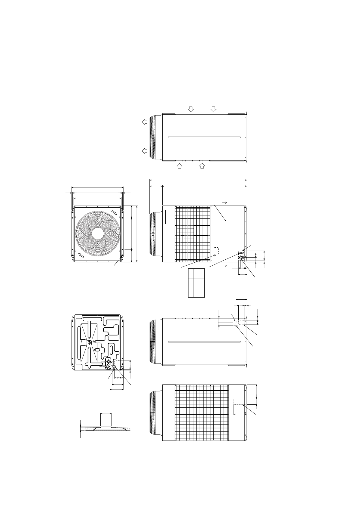
33
3 EXTERNAL DIMENSIONS
33
• Models PUH-8YE/10YE
1 pc.
1 pc.
·
···········
·················
(The connecting pipe is fixed with the unit)
(Attached near the ball valve)
< Accessory >
• Refrigerant (gas) conn. pipe
• Packing for conn. pipe
each 1pc.
4 pcs.
Air outlet
················
,
·························
27
ø
33,
ø
40,
(Painted the same color as the unit body)
ø
• Conduit mouting plate
• Tapping screw 4 ✕ 10
Note Please leave a space under the outdoor unit
910
840
of the bottom plate by the basement)
for the piping When you connect the piping
from the bottom.
(Please be careful not to close the hole
15 880 15
215
225
Unit: mm
Air
inlet
Right side view
Air
inlet
1715
1490
X
Service panel
560
990
Plane view
215
A
12.7
15.88
Oval hole
4 ✕ 2 - 14 ✕ 20
Y
Y
Knockout hole
MOOEL
PUH-8YE
PUH-10YE
X
Refrig. service
valve (liquid)
øA<flare>
40 Knockout hole
7560
ø
<Left side hole for
the power supply>
40
Knockout hole
Front piping hole
83
79
70
149
Refrig. service
194
48 100
16531
valve (gas)
<flange>
4080
Knockout hole
Left piping hole
Left side view
Front view
Cross section X-X
27 Knockout hole
<Left side hole for
the control wiring>
ø
25 160
73 80
198
Note1
Knockout hole
Bottom piping hole
50
237
25.4<brazed>
28.58<brazed>
ø
ø
8 :
10 :
Conn. pipe
251100
234
Rear view
12 5
Knockout hole
Crosss section Y-Y
–5–
Page 8
44
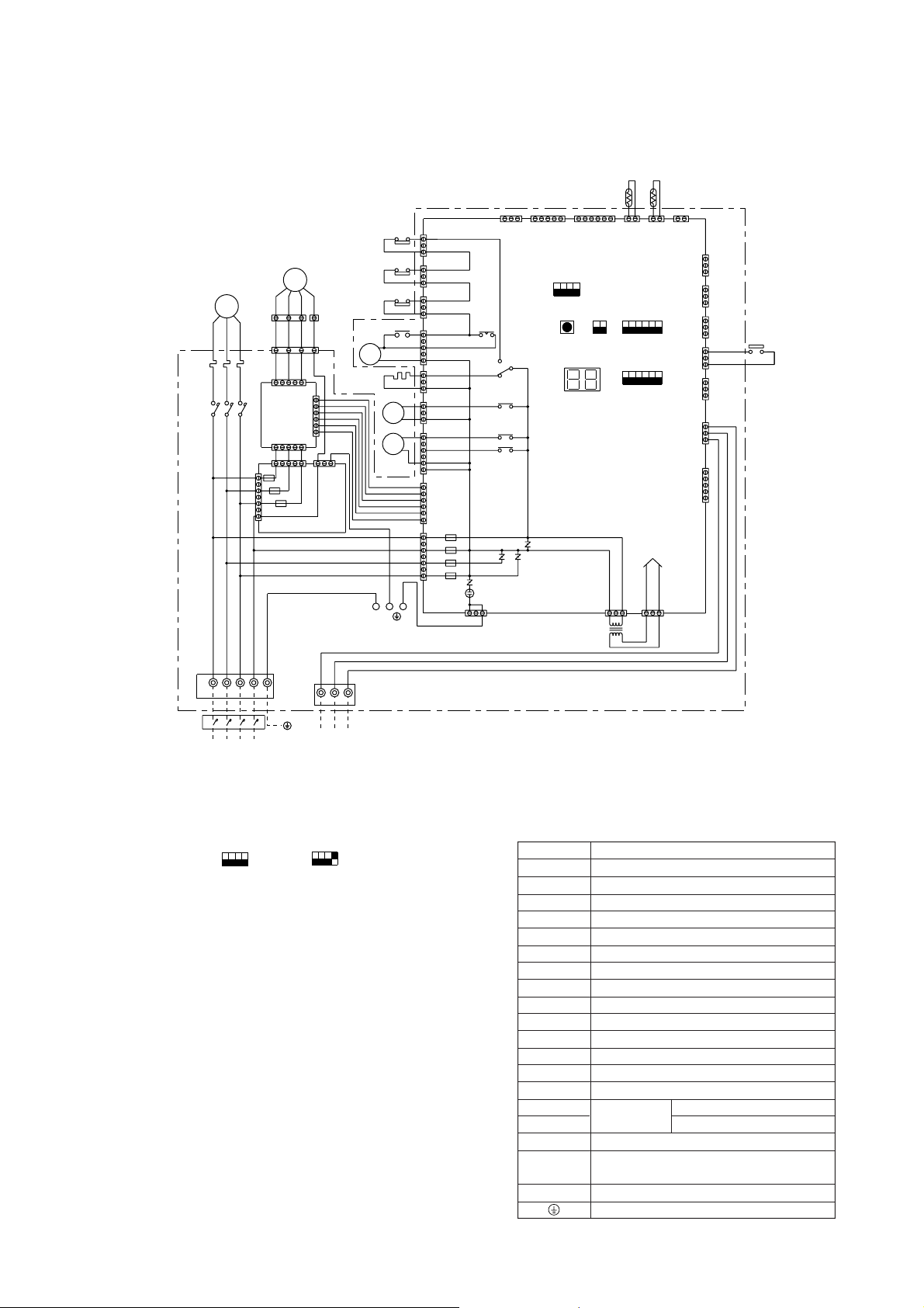
4 ELECTRICAL WIRING DIAGRAM
44
[1] Outdoor Unit
• Models PUH-8YE/10YE
MC
Black
Red
White
51C
52C
Black
White
Red
(3P)
F.C.
BOARD
CNOUT1
(5P)
1
3
5
7
CNIN
(7P)
Blue
MF
1
3
4
1
1
53
CNFAN
(5P)
CNFC2
(6P)
CNPOW
(5P)
3115
F10
F20
F30
N.F.BOARD
Green/Yellow
(1P)
(4P)
1
6
3
CNOUT2
(3P)
49C
51C
63H1
52C
CH
Unit body
52C
21S4
SV1
L1
N
L2
L3
1
3
1
3
1
3
1
3
5
1
3
1
3
1
5
1
6
7
1
CN23
CN22
CN21
CN26
CN25
CN53
CN52
CNFC1
CN20
F01
F04
F02
F03
(3P)
(3P)
(3P)
(5P)
(3P)
(3P)
(6P)
(7P)
(6P)
TH1
TH2
121
CNVMNT
CNMNT
(3P)
(5P)
(6P)
ON
OFF
4
1
SW5
LED1
SW3
ON
OFF
1
SW4
CN28
(3P)
TR
2
X04
X03
X01
X02
X05
CNFG
(3P)
3
1
CN2
(2P)
ON
OFF
1
SW1
ON
OFF
1
SW2
DC power supply
CN34
(3P)
3
1
2
CN3 CN4CN40
(2P)(2P)
CN3D
(3P)
CN3S
(3P)
CN3N
(3P)
6
CN24
(3P)
CN27
(3P)
6
CN81
(3P)
CN51
(5P)
3
1
63H2
3
1
3
1
TB1
NOTE SW5-4 IS OFF IN CASE OF PUH-8YE.
SW5-4 IS ON IN CASE OF PUH-10YE.
L1 L2 L3
L1 L2 L3
Power source
3N~
380/400/415 V
50 Hz
ON
ON
OFF
OFF
1
1
SW5
N
N
4
4
PUH-8YE
TB3
23
1
To indoor unit
ON
ON
OFF
OFF
1
44
1
SW5
PUH-10YE
Note:
1. Be sure to apply earth work to the unit. (Use the earth terminal of TB1.)
Controller Box
Symbol Explanation
Symbol Name
F01~F04
F10~F30
51C
52C
63H1
63H2
TR
MC
MF
CH
X01~X05
SW1~5
21S4
SV1
TH1
TH2
TB1
TB3
49C
FUSE (6.3A 250VAC CLASS F)
FUSE (6.3A 250VAC CLASS F)
OVER CURRENT RELAY
MAGNETIC CONTACTOR (COMPRESSOR)
PRESSURE SWITCH (HIGH PRESSURE)
PRESSURE SWITCH (FOR CONTROL)
TRANSFORMER
ELECTRIC MOTOR OF COMPRESSOR
FAN MOTOR (HEAT EXCHANGER)
CRANK CASE HEATER (COMPRESSOR)
RELAY
SWITCH
4-WA Y VAL VE
SORENOID VALVE
THERMISTOR
LIQUID TEMP
DISCHARGE TEMP
POWER SOURCE TERMINAL BLOCK
INDOOR/OUTDOOR CONNECTION TERMINAL
BLOCK
THERMAL SWITCH (COMPRESSOR)
EARTH TERMINAL
–6–
Page 9
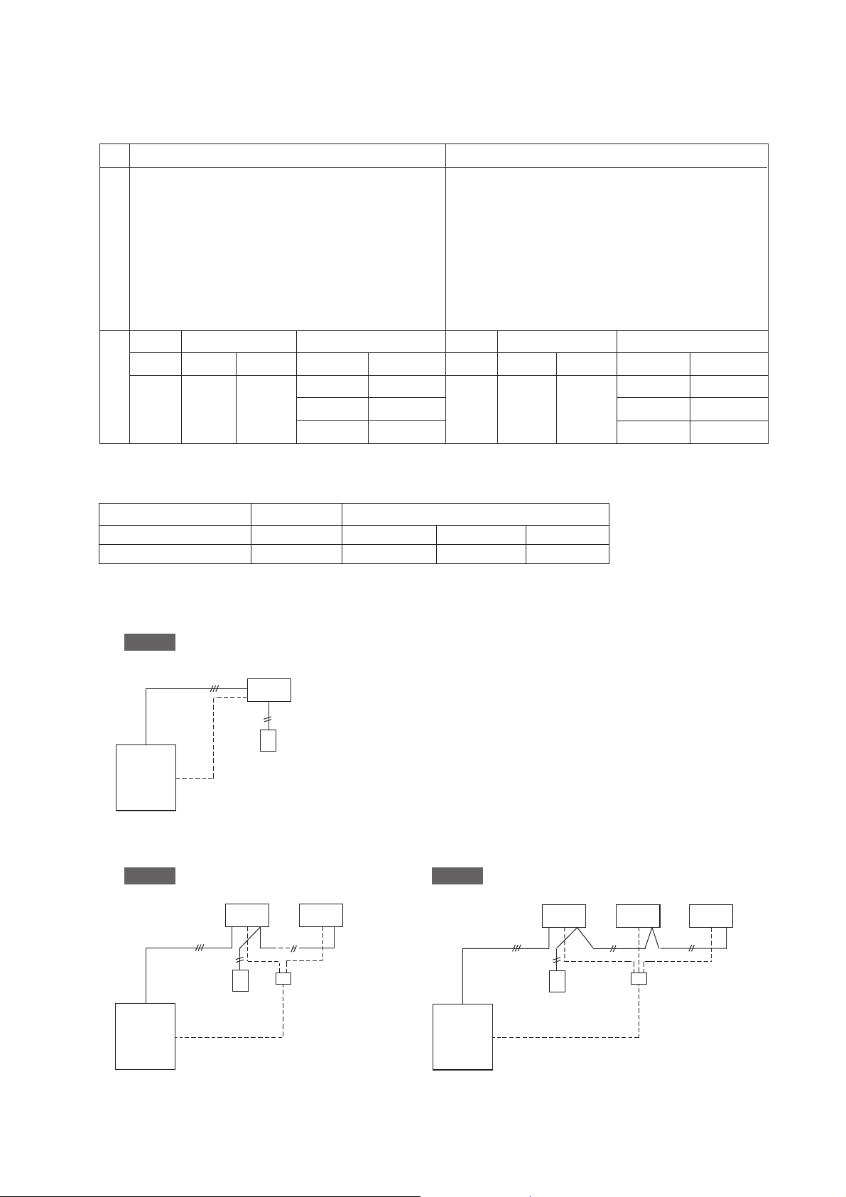
[2] Skelton of Indoor/Outdoor Connection
(1) Multiple systems combination chart
PUH-8YE PUH-10YE
PEH-8YD
PLH-1.6, 2, 2.5KK(H)B
PLH-3AK(H), PLH-4AK(H)S
PKH-1.6, 2, 2.5, 3FK(H)A, PKH-4FK(H)SA
PCH-2, 2.5, 3GK(H)A, PCH-4GK(H)SA
PEH-2.5, 3, EKHA, PEH-4EKHSA
PEHD-1.6, 2, 2.5, 3EK(H)A, PEHD-4EK(H)SA
PEH-10YD
PLH-2, 2.5KK(H)B
PLH-3AK(H), PLH-4, 5AK(H)S
PKH-2, 2.5, 3FK(H)A, PKH-4FK(H)SA
PCH-2, 2.5, 3GK(H)A, PCH-4, 5GK(H)SA
PEH-2.5, 3EKHA, PEH-4, 5EKHSA
PEHD-2, 2.5, 3EK(H)A, PEHD-4, 5EK(H)SA
Single Twin Triple Single Twin Triple
Model Ratio Model Ratio Model Model Ratio Model Ratio Model
33:33:33 2.5+2.5+2.5 33:33:33 3+3+3
Systems Indoor units
8 50:50 4+4 25:25:50 2+2+4 10 50:50 5+5 25:25:50 2.5+2.5+5
20:40:40 1.6+3+3 20:40:40 2+4+4
(2) Multiple-distributor pipes (option)
Twin Triple
Ratio of indoor units 50:50 33:33:33 25:25:50 20:40:40
Multiple-distributor SDD-50WJ-E SDT-111J-E SDT-112J-E SDT-122J-E
(3) System
Single
3-core cable (DC12V)
Outdoor unit
Pipe work
Indoor unit
Transmission line
Remote
controller
Twin Triple
Indoor units
No. 1 No. 2
3-core cable (DC12V)
Remote
controller
Distributor
Transmission
line
3-core cable (DC12V)
Indoor units
No. 1 No. 2 No.3
Remote
controller
Distributor
Transmission
line
Outdoor unit
Pipe work
–7–
Outdoor unit
Pipe work
Page 10
55
5 Technical Data of PUH-8YE/10YE to Meet LVD
55
[1] Standard Operation Data
1 PUH-8YE
Operating condition Cooling Heating
Voltage V
Power source frequency Hz
Indoor air condition (DB/WB) °C
Outdoor air condition (DB/WB) °C
Piping length m
Operating condition
Refrigerant charge kg
Current A
Outdoor unit
Indoor unit
Electrical characteristics
Discharge pressure MPa
Suction pressure MPa
Discharge refrigerant temperature °C
Suction refrigerant temperature °C
Liquid pipe temperature
Refrigerant circuit
Compressor shell bottom temperature °C
Input kW
Compressor current A
Fan current A
Current A
Input kW
(at piping sensor)
°C
380 400 415 380 400 415
50 50 50 50 50 50
27/19 27/19 27/19 20/– 20/– 20/–
35/- 35/– 35/– 7/6 7/6 7/6
7.5 7.5 7.5 7.5 7.5 7.5
7.4 7.4 7.4 7.4 7.4 7.4
13.5 13.6 13.7 12.3 12.4 12.5
7.62 7.62 7.62 6.91 6.91 6.91
12.4 12.5 12.6 11.2 11.3 11.4
1.1 1.1 1.1 1.1 1.1 1.1
1.12 1.12 1.12 1.12 1.12 1.12
0.65 0.65 0.65 0.65 0.65 0.65
1.99 1.99 1.99 1.59 1.59 1.59
0.49 0.49 0.49 0.35 0.35 0.35
85 85 85 75 75 75
777–2–2–2
46 46 46 5 5 5
50 50 50 35 35 35
Note: The values listed above indicate that when connected with the indoor unit PEH-8YD as representative data.
2 PUH-10YE
Operating condition Cooling Heating
Voltage V
Power source frequency Hz
Indoor air condition (DB/WB) °C
Outdoor air condition (DB/WB) °C
Piping length m
Operating condition
Refrigerant charge kg
Current A
Outdoor unit
Indoor unit
Electrical characteristics
Discharge pressure MPa
Suction pressure MPa
Discharge refrigerant temperature °C
Suction refrigerant temperature °C
Liquid pipe temperature
Refrigerant circuit
Compressor shell bottom temperature °C
Input kW
Compressor current A
Fan current A
Current A
Input kW
(at piping sensor)
°C
380 400 415 380 400 415
50 50 50 50 50 50
27/19 27/19 27/19 20/– 20/– 20/–
35/- 35/– 35/– 7/6 7/6 7/6
7.5 7.5 7.5 7.5 7.5 7.5
7.6 7.6 7.6 7.6 7.6 7.6
16.8 16.9 17.0 14.8 14.9 15.0
9.47 9.47 9.47 8.30 8.30 8.30
15.7 15.8 15.9 13.7 13.8 13.9
1.1 1.1 1.1 1.1 1.1 1.1
1.64 1.64 1.64 1.64 1.64 1.64
0.94 0.94 0.94 0.94 0.94 0.94
2.03 2.03 2.03 1.57 1.57 1.57
0.48 0.48 0.48 0.34 0.34 0.34
95 95 95 80 80 80
888–2–2–2
47 47 47 6 6 6
60 60 60 40 40 40
Note: The values listed above indicate that when connected with the indoor unit PEH-10YD as representative data.
–8–
Page 11
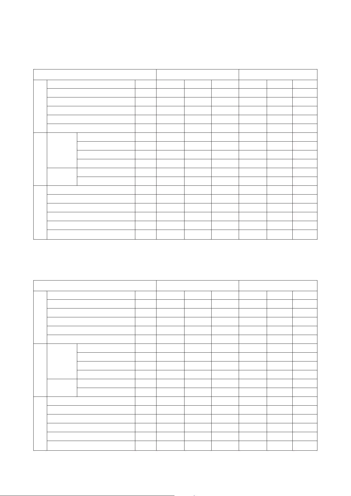
[2] Cooling Capacity Curves
• PUH-8YE/10YE
1.4
I
n
d
o
o
r
i
n
l
e
t
a
i
r
w
e
t
b
u
l
b
t
e
1.2
m
p
.
1.22
<
°
C
W
B
>
1.1
22
20
18
16
1
Capacity ratio
0.8
0.6
-5-3-113579111315171921232527293133353739414345
Outdoor air temp. <°CDB>
[3] Heating Capacity Curves
• PUH-8YE/10YE
1.4
1.2
>
B
D
C
°
<
e
r
u
t
a
r
e
p
m
e
t
b
l
u
b
y
r
Capacity ratio
0.8
1
d
r
i
a
t
e
l
n
i
r
o
o
d
n
I
22
20
18
16
15
20
25
Input ratio
0.9
i
a
t
e
l
n
i
r
o
o
d
n
I
0.7
-5-3-113579111315171921232527293133353739414345
Outdoor air temp. <°CDB>
1.4
1.2
1
Input ratio
0.8
Indoor inlet air dry bulb temperature <°CDB>
e
t
b
l
u
b
t
e
w
r
>
B
W
C
°
<
.
p
m
25
20
15
0.6
-12-10-8-6-4-202468101214
Outdoor air temperature <°CWB>
15.5
–9–
0.6
-12-10-8-6-4-202468101214
Outdoor air temperature <°CWB>
15.5
Page 12

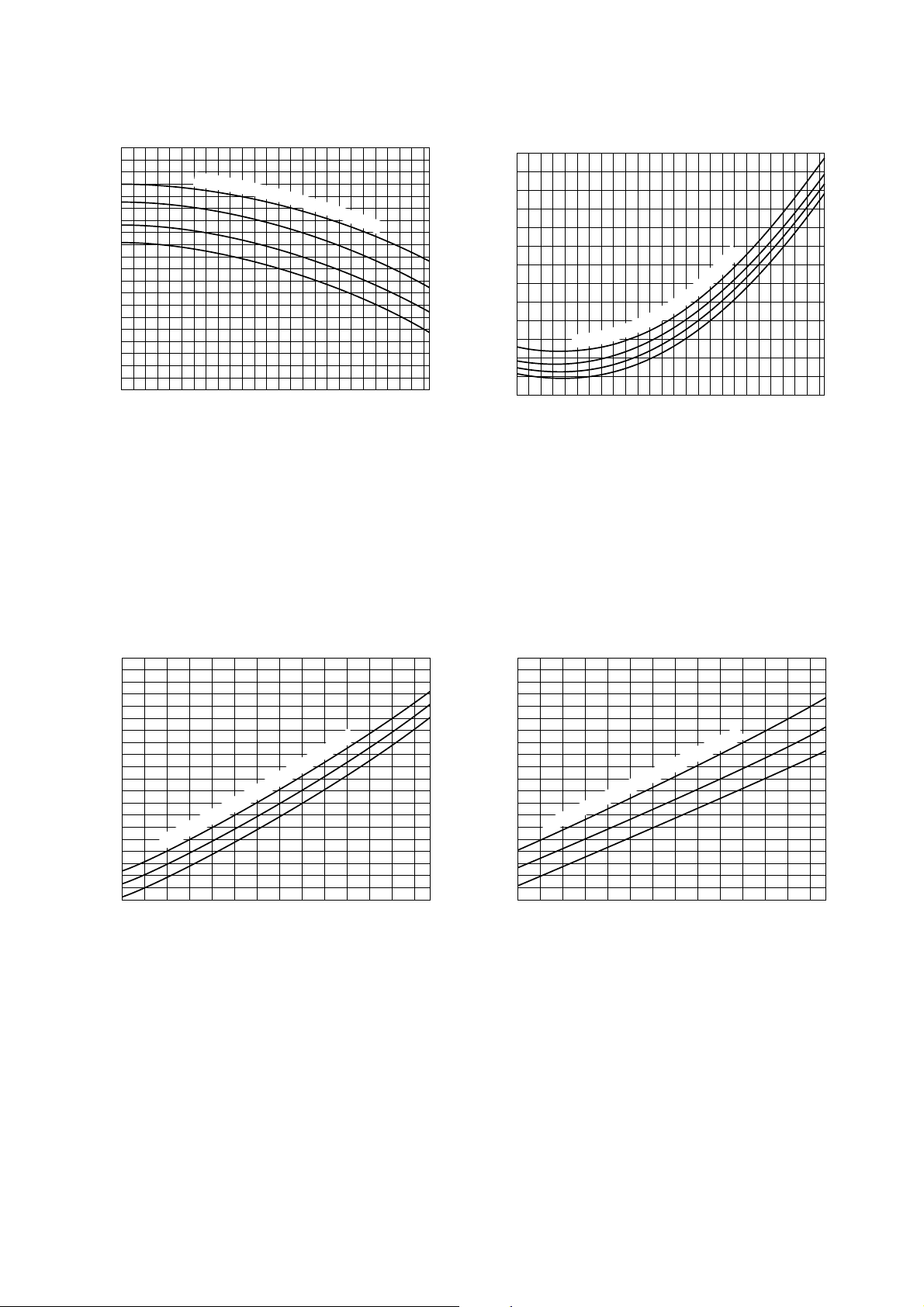
[4] Capacity Reduction Ratio due to Changes in Piping Length
(1) Cooling capacity
PUH-8YE
1
0.9
Capacity ratio
0.8
0 10 20 30 40 50 60 70
Equivalent piping length (m)
(2) Heating capacity
Equivalent piping length
Model name
PUH-8YE
- 30 m 30 - 50 m 50 - 70 m
1.0 0.995 0.99
PUH-10YE
PUH-10YE
1
0.9
Capacity ratio
0.8
0 10 20 30 40 50 60 70
Equivalent piping length (m)
(3) Calculation formula of equivalent piping length
PUH-8YE Equivalent piping length (m) = Actual piping length (m) + (0.47 × Number of bend)
PUH-10YE Equivalent piping length (m) = Actual piping length (m) + (0.5 × Number of bend)
(4) Reduction ratio by frosting
Outdoor unit inlet wet bulb temperature
(°CWB)
6 1.0
4 0.98
2 0.88
0 0.85
–2 0.86
–4 0.89
–6 0.92
–8 0.92
–10 0.92
Heating capacity reduction ratio
–10–
Page 13

[5] Center of Gravity (Outdoor unit)
(1) Caution for Lifting
Warning
Lift unit slowly by suspending rope uniformly
so that the rope will not slip off or unit will not
incline seriously.
Be careful that unit may fall down if the rope is
not in a proper position as the center or
gravity of unit is being inclined.
Protection pad
Use pads properly to
prevent the scratching of
external panel
caused by contact
with sling.
Name plate
Indicates the unit
front side.
Blow 40˚
Hanger rope (Over 7m × 2)
Must be durable against unit weight.
For the lifting of unit for movement, please
be sure to suspend at four points, and not
to give any shock to unit.
Never apply two-point lifting as it is
dangerous.
Service panel
Compressor position
Suspending spot
2-point,front and rear
Model name
PUH-8YE
PUH-10YE
Item
Center of gravity
Inclining to the right
front side of unit.
G
Z
X
Center of gravity (mm)
XYZ
Y
Fasten here properly
to prevent unit from
slipping off from
the sling at lifting.
Net weight
(kg)
330 350 490 205
300 330 510 225
–11–
Page 14

[6] NC Curve (Outdoor unit)
(1) Octave Band Analysis
1 PUH-8YE
Measurement condition
1m
A
1m
B
Sound pressure level in anechoic room
56 dB (A)
70
60
50
40
30
20
OCTAVE BAND PRESSURE LEVEL< dB> 0dB = 0.0002µbar
Approximate minimum
audible limit on
continuous noise
10
63 125 250 500 1000 2000 4000 8000
OCTAVE BAND CENTER FREQUENCIES <Hz>
NC60
NC50
NC40
NC30
NC20
Note: The measuring point is 1m from the bottom of the unit (1m from the front of the unit)
2 PUH-10YE
Measurement condition
1m
A
1m
B
Sound pressure level in anechoic room
57 dB (A)
70
60
50
40
30
20
OCTAVE BAND PRESSURE LEVEL< dB> 0dB = 0.0002µbar
Approximate minimum
audible limit on
continuous noise
10
63 125 250 500 1000 2000 4000 8000
OCTAVE BAND CENTER FREQUENCIES <Hz>
NC60
NC50
NC40
NC30
NC20
Note: The measuring point is 1m from the bottom of the unit (1m from the front of the unit)
–12–
Page 15

66
6 SERVICE DATA
66
[1] Appearance of Equipment
• PUH-8YE/10YE Detail of Electrical Parts Box
(with cover removed) (with Main Board Panel removed)
Transformer
Terminal brock for
Power source
terminal brock
outdoor/indoor control
wiring connection
• PUH-8YE/10YE (with cover removed)
MAIN
BOARD
F. C. BOARD
Magnet contactor for
compresser <52C>
Over current relay
<51C>
N. F. BOARD
Outdoor unit
heat exchanger
Electric parts Box Compresser
Ball valve for refrigerant piping connection <Liquid side> Flare
Ball valve for refrigerant piping connection <Gas side> Flange
–13–
Page 16

• PUH-8YE/10YE (Detail of machine room)
4way valve
Pressure switch
(63H2)
Thermistor
<Liquid temp.>
TH1
Accumulater
Pressure switch
(63H1)
Check joint
(low pressure)
Check joint
(high pressure)
Thermistor
<Discharge temp.>
TH2
Solenoid valve
(SV1)
–14–
Page 17

[2] Refrigerant Circuit
Outdoor unit
Service port
Strainer
Ball valve
High pressure switch
(Protection)
Outdoor heat exchanger
Service port
Indoor heat exchanger
Indoor
units
Capillary
tube
(Heating)
Multiple-distributor
Check valve
Service port
Ball valve
Accumulator
Strainer
[3] Limitation of Refrigerant Piping Length
Pipe length Difference in height
Furthest Total pipe Difference of
pipe length length indoor to inddor
Single
L : Max. 50 m
–
Compressor
Flare connection
Flange connection
Brazing connection
–
High pressure
switch (Control)
Muffler
Service
port
Strainer
Solenoid
valve
<
<
Outdoor~Indoor Indoor~Indoor
H : Max 40 m –
Check valve
Capillary tube (Cooling)
Cooling operation
Heating operation
Amount
of bends
Max. 15
Tiwn
T riple
L+Ra : Max. 50 m
L+Rb : Max. 50 m
L+Ra : Max. 50 m
L+Rb : Max. 50 m
L+Rc : Max. 50 m
L+Ra+Rb :
Max. 70 m
L+Ra+Rb+Rc :
Max. 70 m
Ra - Rb : Max. 8 m
Ra - Rb : Max. 8 m
Ra - Rc : Max. 8 m
Rb - Rc : Max. 8 m
H : Max. 40 m h : Max. 1 m
H : Max. 40 m h : Max. 1 m
Note: 1. The number of bend shall be within 8 points between (L+Ra) (L+Rb) (L+Rc).
Single
Indoor
unit
Outdoor
unit
L
H
Twin Triple
Indoor
Outdoor
unit
L
Indoor
unit
Ra
Rb
unit
h
H
Outdoor
unit
Indoor
unit
Max. 15
(Note: 1)
Max. 15
(Note: 1)
Rc
Indoor
unit
h
H
Indoor
unit
Rb
Ra
L
–15–
Page 18

[4] Refrigerant Piping
Model Gas pipe Liquid pipe
Outdoor unit
PUH-8YE ø25.4 ø 12.7
PUH-10YE ø
28.58 ø 15.88
1.6, 2, 2.5, 3 ø 15.88 ø9.52
4, 5 ø19.05 ø 9.52
Indoor unit
8ø
10 ø28.58 ø
25.4 ø 12.7
15.88
[5] Refrigerant Charge
Model
PUH-8YE
PUH-10YE
L: Main section actual length R
Amount of infusion of
coolant at ex-factory
R22 6.5 kg
R22 6.5 kg
a +Rb +Rc +Rd: Join section actual length
0.05 × L + 0.026 × (R
× amount of indoor units. (kg)
0.08 × L + 0.026 × (Ra +Rb +Rc +Rd) + 0.5
× amount of indoor units. (kg)
The value of calculation result at the second decimal place must be rounded up to the first decimal place.
(e.g. 2.22 kg must be rounded up to 2.3 kg)
Additional refrigerant charge
a +Rb +Rc +Rd) + 0.5
[6] Operation Rage
24
Indoor air temperature (°CWB)
15
-5 46
Outdoor air temperature (°CDB)
Cooling Heating
27
Indoor air temperature (°CDB)
15
–12 15.5
Outdoor air temperature (°CWB)
–16–
Page 19

77
3N~
380/400/415 V
50 Hz
outdoor
Fuse
Fuse
DC5V for
microcomputer
Electrical
terminal block
Over current
relay
Magnetic
contractor
4-way valve, Gas
bypass solenoid
valve, crankcase
heater
Communication
circuit
Transformer
Fan control
Auxiliary relay
Compressor
Outdoor fan
Indoor/outdoor
connection terminal
block
7 CONTROL
77
[1] Composition of Control
1 Function block diagram
[2] Control specifications
(1) Protection functions
1) The main protection devices for the outdoor unit are:
1 High pressure protection (63H1)
2 Compressor overcurrent protection (51C)
3 Inner thermostat (49C, compressor)
4 Liquid temp thermistor trouble (TH1)
5 Discharge temperature protection (TH2
6 Discharge temp thermistor trouble (TH2)
2) When tripping of a detection device is sensed, the check mode is entered and the compressor is stopped. (After 3
minutes, the compressor restarts.) Thereafter, the compressor is stopped when the specified number of check
modes or greater is sensed within the check time.
>
135 °C)
=
Protection functions
1 High pressure protection
(63H1)
2 Compressor overcurrent
protection (51C)
3 Inner thermostat (49C,
compressor)
4 Liquid temp thermistor
trouble (TH1)
5 Discharge temperature
protection (TH2
>
135 °C)
=
6 Discharge temp ther-
mistor trouble (TH2)
3) Check mode is released by stopping operation, changing the operation mode, or check mode time up. A check
mode is also released by stopping of operation by remote controller.
Operation value
2.94 MPa
8YE: 22 A
10YE: 27 A
105 ± 5 °C
Less than –39 °C or
greater than 88 °C
Greater than 135 °C
Less than 0 °C or
greater than 216 °C
Detection condition
Compressor operating
Compressor operating
Compressor operating
Compressor operating except for
10 minutes at end of defrosting, 7
minutes while compressor starting
Compressor operating
Compressor operating except for
10 minutes at end of defrosting, 5
minutes while compressor starting
Number of
check modes
0
1 time
1 time
1 time
2 times
1 time
Check time
–
30 minutes
30 minutes
30 minutes
30 minutes
30 minutes
4) Detected check mode history (newest) and abnormality history (last 2 times) are memorized and are displayed on
the segment by circuit board DIP switch setting.
The operation mode when the newest abnormality was generated, the thermistor temperature (TH1,2), and the
thermostat ON time can also be displayed.
–17–
Page 20

(2) Compressor, 4-way valve, and crankcase heater control
1) Determines the operation mode based on the indoor/outdoor communication data and operates the air conditioner.
2) Compressor control has a function which prevents the compressor from restarting within 3 minutes.
3) The 4-way valve is always ON during heating (except during defrosting). In other modes, it is OFF. However, when
the operation mode was changed from heating to stop, the 4-w ay valv e is turned off 10 minutes after the compressor
was stopped.
4) While the compressor is stopped, the crankcase heater remains ON. (OFF while the compressor is operating.)
5) When the operation mode is changed while the compressor is operating, the compressor stops and 3 minutes later
restarts in the new mode.
(3) Fan control
Controls the fan speed based on the piping temperature (TH1) to perf orm cooling at low outdoor temperatures and heating
at high outdoor temperatures.
1) Control at cooling
1 When the compressor stops, the fan stops (fan output=0%).
2 When the power is turned on, or when the compressor is restated after it has been stopped for 30 minutes or
longer, the piping temperature ( TH1) determines the fan output.
When TH
>
25 °C Fan output = 100 %
=
When TH < 25 °C Fan output = 60 %
3 When the compressor is restarted within 30 minutes after it has been stopped, the fan step before the compres-
sor was stopped is selected. Ho wever, when the fan output w as under 30% when the fan was stopped, 30 % is
selected.
4 When the mode was changed from heating to cooling, the fan step conforms to item 2.
5 T w o minutes after the fan is started, the fan step (number of units) is controlled every 30 seconds based on the
piping temperature (TH1).
6 When TH1 reaches 50 °C or higher, or when the control high pressure switch (63H2) tripped, the fan output
becomes 100 %.
7 Fan output while the compressor is operating is within the 20 % to 100 % range.
• FAN step
The following expression determines the next fan step count nj+1:
nj+1 = nj+∆nj nj: Current fan step, ∆nj: Displacement step amount
nj control
• If nj+1
• If nj+1
• If TH1
>
100 % nj+1 = 100 %
=
<
20 % nj+1 = 20 %
=
>
50 °C or 63H2 is “OFF” nj+1 = 100 %
=
FAN ∆nj Outputs are all %.
Condensation temperature TH1
Target condensation
temperature 31 °C
<
20
nj < 50
=
<
<
nj
Current
output
50
100
=
=
t > 49 °C
10
t = 49
t = 46
t = 43
t = 40
t = 36
t = 33
t = 29
t = 26
~
~
t > 46
~
t > 43
t > 40
5
3
2
2
4
3
2
~
t > 36
2
2
~
t > 33
1
1
~
t > 29
0
0
~
t > 26
–1
–1
~
t > 23
–2
–2
t = 23
t > 20
–3
–4
<
~
t
20 °C
=
–5
–10
* IN the night mode, the maximum value of nj is 80%. (When TH1 < 50 °C)
–18–
Page 21

2) Control at heating
1 When the compressor is stopped and during defrosting, the fan is stopped.
2 When the power is turned on, or when the compressor is restarted after being stopped for 30 minutes or longer,
the piping temperature (TH1) determines the fan step.
TH1 > 8 °C Fan output = 60 %
<
TH1
8 °C Fan output = 100 %
=
3 When the compressor is restarted within 30 minutes, the fan step is the step before the compressor was stopped.
4 When the mode is changed from cooling to heating, the fan step conforms to item 2.
5 When returning from defrosting, the fan step is the step before defrosting.
6 Two minutes after the fan was restarted, the fan step is controlled every 30 seconds based on the piping tem-
perature (TH1).
7 When TH1 is –5 °C or lower, the fan output is made 100 %.
• FAN step
The following expression determines the next fan step count nj+1:
nj+1 = nj+∆nj nj: Current fan step, ∆nj: Displacement step amount
nj control
• If nj+1
• If nj+1
>
100 % nj+1 = 100 %
=
<
20 % nj+1 = 20 %
=
• If TH1 < –5 °C nj+1 = 100 %
FAN ∆nj Outputs are all %.
Evaporation temperature TH1
Target evaporation
temperature 12 °C
T > 19 °C
T = 19
~
T > 17
T = 17
~
T > 15
T = 15
~
T > 13
T = 13
~
T > 11
T = 11
~
T > 8
T = 8
~
T > 6
T = 6
~
T > 4
T = 4
~
T > 2
T = 2
~
T > 0
T
<
0 °C
=
nj + 1
<
100
=
–10
–4
–2
20
Current
output
<
=
(4) Defrosting control
1) When the following conditions are satisfied, defrosting starts:
1 When the integrated compressor operation time has exceeded T
temperature (TH1) is below –2 °C
2 When the integrated compressor operation time has exceeded 30 minutes and the piping differential tempera-
ture is ∆TH1
>
8, TH1
=
<
–2 °C
=
Piping differential temperature ∆TH1 = TH10 – TH1
2) The defrosting prohibit time T
<
T
2
3 (minutes) T1 120 (minutes)
=
3 < T
2
7 < T
2
2 < 15 40
10 < T
T
2 = 15 30
1 is set as following based on the defrosting time T2:
<
780
=
<
10 60
=
Note: When the compressor was stopped during defrosting, T1 = 30 min utes is set to recognize the stop as defrost-
ing end.
–1
0
1
2
2
3
1 (initial setting 50 minutes) and the piping
4
Current piping temperature
Piping temperature 10 minutes after starting or
10 minutes after returning from defrosting
Note: T1 is reset at the end of defrosting, or by cooling
ON command.
10
3) During defrosting, all the outdoor fans are stopped and the bypass solenoid valve (SV1) is turned ON and the 4-wa y
valve (21S4) is turned OFF.
4) When the following conditions are satisfied, defrosting ends:
1 T
2
2 2 < T
3 T
2 =15 minutes
<
2 mins TH1
=
2 < 15 minutes TH1
>
40 °C
=
>
8 °C continuous 2 minutes
=
5) When the fan and 4-way valv e (21S4) are turned ON at the end of defrosting, the heating mode is reset. Two minutes
after defrosting reset, the bypass solenoid valve (SV1) turns OFF.
–19–
Page 22

(5) Bypass solenoid valve control (SV1)
1) Control at cooling
1 While the compressor is stopped, the solenoid valve is OFF.
2 When the power is turned on, or when the compressor is restarted after it has been stopped for 30 minutes or
longer, if the Liquid temperature (TH1) is 25 °C or higher then the solenoid valve turns ON for 2 minutes.
3 When the mode is changed from heating to cooling, solenoid valve operation conforms to item 2.
2) Control at heating
1 While the compressor is stopped, the solenoid valve is OFF.
2 When the power is turned on, or the compressor is restarted after it has been stopped for 30 minutes or longer,
the solenoid valve turns ON for 2 minutes.
3 When the mode is changed from cooling to heating, the solenoid valve turns ON for 2 minutes at starting.
4 When the control pressure switch (63H2) trips, the solenoid valve turns ON.
5 If 63H2 resets 15 minutes after tripping, the solenoid valve turns OFF.
6 During defrosting, the solenoid valve turns ON.
(6) Service functions
1) Abnormality history clear
1 When DIP SW1-2 is turned ON while the compressor is operating or stopped, the abnormality history is cleared.
–20–
Page 23

[3] Function of switches and connectors (outdoor unit)
(1) Function of switches
1) Function of switches
(Normal mode)
Kind of
switch
DIP SW
Tact SW
DIP SW
DIP SW
Switch
SW1
CN33
When
open
(Normal)
SW2
SW3
SW4
SW5
Pole
1
2
Abnormality history clear
Function
None
3
4
None
5
6
1
2
3
Self diagnosis
4
5
6
Mode input register
1
2
1
3-phase power source
2
3
Cooling only switching
4
None
detection
Model setting
–
–
Normal mode
SW3 = Unrelated
Operation by switch operation
ON OFF
––
Clear Normal
See pages 22 to 24.
Register Normal
––
––
Do not Do
Cooling only Heat pump
PUH-10YE PUH-8YE
Switch effec-
tive timing
–
Running or
stopped
–
–
Running or
stopped
stopped
–
–
–
–
When power
turned on
When power
turned on
2) Switch functions at set mode change
Set input mode
1
8 °C continuous 2 minutes
Switch effective
timing
stopped
stopped
stopped
Kind of
switch
DIP SW
Switch
SW1
When
CN33
shorted
(mode
switching)
Pole
1
2
3
4
Defrosting end switching
5
6
Function
None
Night mode
Defrosting prohibit time
switching
None
CN33 = short SW3 = ON*
Operation by switch operation
ON OFF
––
Night mode Normal mode
12 °C continuous 2 minutes
Fixed Training
––
*1 Mode input is entered by SW3 OFF→ON change (___↑). Press and hold do wn SW3 f or about 2 seconds. The set
mode can be registered according to the outdoor unit setting information on page 24.
Remarks
Note: After changing the mode by CN33 shorting (mode switching), return to the normal mode by opening CN33.
3) Connector function assignment
Type
Connector
Connector
CN31
CN32
CN33
Function
None
Function test
DIP switch mode switching
Operation by open/short
short open
––
Function mode Normal
Mode switching Normal
Switch effec-
tive timing
At initialization
stopped
–
–
–
–21–
Page 24

<Outdoor unit operation monitoring function>
The operation status and check code contents can be ascertained by means of the 2-digit number and symbol on digital
display light emitting diode LED2 by operating DIP switch SW2.
<Description of operation of digital display light emitting diode (LED2)>
• When ON (normal operation): Displays the operation mode.
SW2
LED2
[Tens digit: Operation mode]
Display Operation mode
O stopped
C Cooling/Dry
H Heating
d Defrost
ON
[Units digit: Relay output]
Display Compressor 4-way valve Bypass solenoid valve
0– – –
1– – ON
2 – ON –
3 – ON ON
123456
ON
OFF
(Load status)
4ON – –
5ON – ON
6ON ON –
7ON ON ON
• When blinking (Operation stopped by tripping protection device): Displays the check mode
• PUH-8YE/10YE
Display Check contents (operating)
U2 49C trip, Compressor discharge temperature abnormal
U3 Compressor discharge temp thermistor (TH2) open/short
U4 Liquid temp thermistor (TH1) open/short
U6 Compressor overcurrent protection trip (51C trip)
UE High pressure protection (63H1 trip)
Self diagnosis by SW2
• PUH-8YE/10YE
SW2 setting Display contents Description of display Unit
–39 - 88
(When 0 °C or lower, “–”and temperature are displayed
alternately.)
<Example> When –10,
°C
123456
ON
OFF
Liquid temperature
(TH1)
–39 - 88
every other second
–
←→ 10
123456
ON
OFF
Discharge temperature
0 - 216
0 - 216
(When 100 °C or higher, 100s digit and 10s and units
digits are displayed alternately.)
<Example> When 115,
°C
every other second
1
←→ 15
123456
ON
OFF
FAN output
0 - 100
0 - 100
(When 100 or higher, 100s digit and 10s and units digits
are displayed alternately.)
<Example> When 100,
%
every other second
1
←→ 00
–22–
Page 25

SW2 setting Display contents Description of display Unit
0 - 999
(When 100 or higher, 100s digit and 10s and units digits
are displayed alternately.)
<Example> When 425,
100 times
123456
ON
OFF
Number of compressor
ON/OFF
0 - 999
every other second
4
←→ 25
123456
ON
OFF
123456
ON
OFF
123456
ON
OFF
123456
ON
OFF
Compressor integrated operation time
0 - 999
Newest check code
Newest outdoor unit
abnormality
Check display
Operation mode when
abnormality occurred
Liquid temperature
(TH1) when abnormality occurred
– 39 - 88
0 - 999
(When 100 or higher, 100s digit and 10s and units digits
are displayed alternately.)
<Example> When 245,
every other second
2
←→ 45
When no check mode,“00”
<Example> When piping thermistor abnormal U4
Operation mode when abnormally stopped
<Example> Comp only ON at cooling operation C4
–39 - 88
(When 0 °C or lower, “–” and temperature are displayed
alternately.)
<Example> When –15,
every other second
–
←→ 15
10 hours
Code display
Code display
°C
123456
ON
OFF
123456
ON
OFF
123456
ON
OFF
COMP discharge
temperature (TH2)
when abnormality
occurred
0 - 216
Check code history (1)
(newest)
Abnormal unit No. and
check code inverted
display
Check code history (2)
(One before newest)
Abnormal unit No. and
check code inverted
display
0 - 216
(When 100 or higher, 100s digit and 10s and units digits
are displayed alternately.)
<Example> When 130,
every other second
1
←→ 30
When no abnormality history
“0”, “←→”, “–”
When no abnormality history
“0”, “←→”, “–”
°C
Code display
Code display
–23–
Page 26

SW2 setting Display contents Description of display Unit
0 - 999
(When 100 or higher, 100s digit and 10s and units digits
are displayed alternately.)
<Example> When 245,
Minutes
123456
ON
OFF
Current thermostat
ON time
0 - 999
every other second
2
←→ 45
123456
ON
OFF
123456
ON
OFF
123456
ON
OFF
123456
ON
OFF
Outdoor unit set
information 1
Outdoor unit set
information 2
FAN output at abnormal stop
0 - 100
Thermostat ON time
until abnormal stop
0 - 999
Outdoor unit capacity is displayed as function code.
Model name function code
PUH-8YE 20
PUH-10YE 25
Outdoor unit set information 1 Function setting (display valves)
3-phase power source detection Do (1) Do not (0)
Cooling only switching Cooling only (2) H/P (0)
Tens digitUnits digit
Night mode Night mode (1) Normal mode (0)
Defrosting end time
Defrosting prohibit time Fixed (4) Training (0)
Set information display values are added and displayed at each position.
12 °C continuous 2 minutes
(2)
8 °C continuous 2 minutes
0 - 100
(When 100 or higher, 100s digit and 10s and units digits
are displayed alternately.)
<Example> When 100,
every other second
1
←→ 00
0 - 999
(When 100 or higher, 100s digit and 10s and units digits
are displayed alternately.)
<Example> When 245,
every other second
2
←→ 45
(0)
Code display
Code display
%
Minutes
–24–
Page 27

[4] Simple parts check method
• PUH-8YE/10YE
Part name
Thermistor (TH1) <Liquid
temperature detection>
Thermistor (TH2) <Discharge temperature detection>
Fan motor
Thermal protector
trip temperature
135 ± 5 °C
White
Red
Black
Blue
Compressor
Judgment instructions
Disconnect the connector and measure the resistance value with a multimeter.
(Ambient temperature 10 °C to 30 °C)
Abnormal
Open or short
TH1
TH2
Normal
4.3 kΩ~9.6 kΩ
160 kΩ~410 kΩ
(Based on thermistor characteristic table (next page))
Measure the resistance value across the terminals with a multimeter. (Winding
temperature 20 °C)
Motor lead wire
Between 2 phases
Normal
22.8 Ω
Abnormal
Open or short
Measure the resistance value across the terminals with a multimeter. (Winding
temperature 20 °C)
Normal
PUH-8YE
Each phase 1.51 Ω
PUH-10YE
Each phase 1.03 Ω
Abnormal
Open or short
Open or short
–25–
Page 28

[5] Reference Data
50
40
30
20
10
0
–20 –10 10 20 30 40 500
25
20
15
10
5
0
90 100 110 120
<Thermistor characteristic table>
Low temperature thermistor Thermistor <Liquid temperature detection> (TH1)
Thermistor <Liquid temperature detection> (TH1)
Thermistor Ro = 15 kΩ ± 3 %
B constant = 3,460 kΩ ± 2 %
Rt = 15 exp {3,460 (–––––– – ––––)}
11
273 + t 273
0 °C: 15 kΩ
10 °C: 9.7 kΩ
20 °C: 6.4 kΩ
25 °C: 5.3 kΩ
30 °C: 4.3 kΩ
40 °C: 3.1 kΩ
<Low temperature thermistor>
Resistance
Temperature
High temperature thermistor Thermistor <Discharge temperature detection> (TH2)
Thermistor (Discharge temperature detection) (TH2)
<High temperature thermistor>
Thermistor R120 = 7.465 kΩ ± 2 %
B constant = 4,057 kΩ ± 2 %
Rt = 7.465 exp {4,057 (–––––– – ––––)}
11
273 + t 393
20 °C: 250 kΩ 70 °C: 34 kΩ
30 °C: 160 kΩ 80 °C: 24 kΩ
40 °C: 104 kΩ 90 °C: 17.5 kΩ
50 °C: 70 kΩ 100 °C: 13.0 kΩ
60 °C: 48 kΩ 110 °C: 9.8 kΩ
Resistance
Temperature
–26–
Page 29

[6] Self-diagnosis and troubleshooting
<Abnormality detected during unit operation: Outdoor unit>
(1) PUH-8YE/10YE
Outdoor
unit LED
display
U2
U3
U4
U6
UE
Meaning of abnormality display and
abnormality troubleshooting
Discharge temperature abnormal
(comp)
When the discharge thermistor temperature (TH2) exceeds 135 °C while
the compressor is operating, an abnormality is recognized.
49C trip
When connector (49C) opens while
the compressor is operating, an abnormality is recognized.
49C Inner thermostat (Comp)
105 ± 5 °C
Discharge temp thermistor (TH2)
open or shorted.
When an open (0 °C or lower) or
short (216 °C or higher) is detected
while the compressor is operating, an
abnormality is recognized.
(Detection is disabled for 5 minutes
at compressor starting.)
Liquid temp thermistor (TH1) open
or shorted.
When an open (–39 °C or lower) or
short (88 °C or higher) is detected
while the compressor is operating, an
abnormality is recognized. (Detection
is disabled for 7 minutes beginning
from 10 seconds after the compressor starts and for 10 minutes after
return from defrosting.)
Compressor overcurrent trip
When the current value reaches the
overload set value or higher while the
compressor is operating, an abnormality is recognized.
PUH-8YE............................... 22 A
PUH-10YE............................. 27 A
High pressure abnormal (63H1
trip)
Detected (2.94+0
MPa) by 63H1 trip
-0.15
while compressor is operating.
63H1:Pressure switch (high pres-
sure)
OFF: 2.94
+0
-0.15
(MPa)
ON: 2.35 ± 0.2 (MPa)
1 Compressor overheating due to insuf-
ficient refrigerant.
2 Thermistor faulty. (TH2)
3 Outdoor controller board faulty.
1 Compressor overheating operation due
to insufficient refrigerant.
2 Connector (49C) on indoor controller
board dislodged or contact faulty.
3 49C disconnected, or contact faulty.
4 RST not connected properly.
5 Missing phase.
6 Outdoor controller board faulty.
1 Connector (CN3) dislodged or connect
faulty .
2 Thermistor faulty. (TH2)
3 Outdoor controller board faulty.
1 Connector (CN2) dislodged or contact
faulty.
2 Thermistor faulty.
3 Outdoor controller board faulty.
1 Overload operation exceeding unit us-
age range limit.
2 Power supply terminal voltage low.
3 Power supply missing phase.
4 Compressor motor faulty.
5 Compressor locked.
6 Connector (CN22) on outdoor control-
ler board dislodged or contact faulty.
7 51C disconnected or contact faulty.
1 Started with ball valve closed.
2 Connector (CN21) on outdoor control-
ler board dislodged or contact faulty.
3 63H1 disconnected or contact faulty.
4 Indoor filter clogged. Power reset de-
tected during heating overload operation (Heating).
5 Low indoor unit air flow (heating).
6 Low outdoor unit air flow (cooling).
7 Part faulty.
Cause
Judgment method and remedy
1 Check input super heat.
Check for refrigerant leakage and check
piping length.
Charge with additional refrigerant.
23
T urn off power and restart operation and
check if “U3” is displayed within 8 min-
utes.
When “U3” is displayed, carry out “U3”
processing.
(Do not replace board at “U2” display
only.)
1 Check intake super heating.
Check for refrigerant leakage.
Charge additional refrigerant.
23
After checking connection, restart and
check operation.
45
Check power supply connections.
6 Replace outdoor controller board.
1 Check connector contact and thermistor
wire.
2 Check thermistor resistance value, or
check temperature by microcomputer.
(Check using SW2 self-diagnosis func-
tion.)
See page 26.
3 Replace outdoor controller board.
(Replace board after sufficiently check-
ing 1 and 2.)
1 Check connector contact and thermistor
wire.
2 Check thermistor resistance value or
check temperature by microcomputer.
(Check using SW2 self-diagnosis func-
tion.)
See to page 26.
3 Replace outdoor controller board.
(Replace board after sufficiently check-
ing 1 and 2)
1 Check usage conditions.
(Check for short cycle operation.)
2 Check power supply voltage.
3 Check wiring for breaks and faulty con-
tact.
4 Check motor winding resistance (See
page 25.)
5 Replace compressor.
67
After checking connections, restart and
check operation.
1 Check if ball valve is fully open.
2
Repair connector.
3
4 Check indoor filter.
5 Check flow duct static pressure and for
faulty fan motor.
6 Check for faulty outdoor fan motor.
7 Replace pressure switch.
–27–
Page 30

(2) Setting method of system
Single
Remote
controller
Twin
Remote
controller
Triple
CN40
CN40
OFF
OFF
ON
ON
SW6
1 2 3 4
SW6
1 2 3 4
Outdoor unit
Outdoor unit
OFF
•Setting of SW6
All set to OFF (at factory shipment)
SW6
ON
1 2 3 4
•Setting of SW6
No. 1 indoor unit SW6-1 : ON
No. 2 indoor unit SW6-2 : ON
No. 1 No. 2 No. 3
Remote
controller
CN40
OFF
SW6
ON
1 2 3 4
Outdoor unit
DIP SW6 for Single, Twin, Triple setting (Indoor circuit board)
ON
Single Twin Triple
SW6–1 OFF ON: No. 1 indoor unit only ON: No.1 indoor unit only
1234
OFF
SW6–2 OFF ON: No. 2 indoor unit only ON: No. 2 indoor unit only
SW6–3 OFF OFF ON: No. 3 indoor unit only
SW6-4 OFF OFF ON
OFF
ON
SW6
1 2 3 4
•Setting of SW6
No. 1 indoor unit SW6-1, 4: ON
No. 2 indoor unit SW6-2, 4: ON
No. 3 indoor unit SW6-3, 4: ON
ON
OFF
SW6
1 2 3 4
Removable of CN40
• Please remove the CN40 of No. 2 indoor unit at Twin system and remove the CN40 of No. 3 indoor unit at Triple system.
–28–
Page 31

(3) Judgment by setting of trial run mode
Symptom Causes Service procedures
The “CENTRALLY CONTROL” display does not disappear, and the
switch is ineffective.
A
Faulty receiving circuit of remote
controller, or faulty indoor tr ansmission circuit.
Address is being set to DIP-SW17
of remote controller, or to DIP-SW2
of indoor unit.
Remote controller is being connected with timer adapter.
(1) Check for the correct setting of DIP SW17 of re-
mote controller.
(2)
a) Turn DIP SW17-7 of remote controller for ser-
vices ON (acting as subordinate remote controller), and connect it to remote controller terminal bed.
b) Turn local switch ON, and check whether the
display of “CENTRALLY CONTROL” has been
disappeared.
•Replace the remote controller if it is disappeared.
•When it has not been disappeared, check DIPSW2 for correct setting, and replace indoor controller if the setting is correct.
At turning the operation SW of remote
controller on, “E0” is displayed for 2
~ 4 seconds after operation display.
B
Turning operation switch of remote
controller ON generates operation
display with electronic sound, but disappears soon.
Faulty remote controller transmission/receiving circuit, or faulty indoor unit transmission/receiving
circuit.
Erroneous wiring of indoor/outdoor
connecting line, or reset function is
being effective by overcurrent
deection due to the short circuit of
drain sensor.
(1) Turn DIP SW17-7 of remote controller for services
ON (acting as subordinate remote controller), and
connect it to remote controller terminal bed.
(2) Turn local switch ON, and after 5 seconds, con-
firm the liquid crystal display has been distinguished. If “CENTRALLY CONTROL” is lighting,
return to the item A.
(3) Turn the operation switch of subordinate remote
controller, and check the display of both remote
controllers after 5 seconds elapsed.
1
Operation
display
2
Operation
display
3
No display
4
No display
Remote
controller
Subordinate
remote controller
E0 display
Operation display
E0 display
Operation display
Faulty spot
Faulty indoor unit
Faulty remote
controller
Faulty indoor unit/
remote controller
Faulty remote
controller
(1) Check for the wiring connection of indoor/outdoor
connecting line.
a)
1
2
Indoor Outdoor
3
1
2
3
C
and heating trial operation
b)
Reset by cooling trial operation
1
2
Indoor Outdoor
3
1
2
3
Reset at heating trial operation
–29–
Page 32

Symptom Causes Service procedures
c)
1
2
Indoor Outdoor
3
Reset by cooling trial operation
and heating trial operation
1
2
3
C
T urning the operation SW of remote
controller ON keeps all lights being
distinguished, and generates no
electronic sound.
D
The piping temperature code of liquid crystal display does not change,
or “P8” is displa yed at about 10 min-
E
utes after operation start.
Short circuit of remote controller
wiring.
Faulty power source circuit of indoor controller, or improper contact
of CN40.
Disconnection of transformer, or
improper contact of CN40
Blown fuse (F)
Local switch OFF
d)
1
2
Indoor Outdoor
3
1
2
3
Reset at heating trial operation
(2) Measure the resistance value between 1~3 of
drain sensor connector (CN50). Normal if it is
about 82 Ω.
* When both (1) and (2) are normal, replace indoor
controller.
(1) Check for remote controller terminal voltage
a) At no voltage found,
Remove the wiring of remote controller terminal, and check the voltage between wiring.
•If the voltage shows DC6V ~ DC12V, replace
remote controller as it is faulty. (Short circuit
inside remote controller)
•If no voltage is found, check for indoor side.
1) AC380 ~ 415V check
2) Fuse (F)
3) Transf ormer connector CN4T
4) Connector CN40
* When no trouble is found for the items 1) ~ 4)
above, replace indoor controller.
Please refer to ” ” on the next page.
–30–
Page 33

(4) Check mode display and description
Display
of liquid
crystal
Symptom Causes Remedy
Transmission/receiving
error
No reply of indoor to
the signal of remote
controller
Inlet sensor trouble
Piping sensor trouble
Transmission/receiving
error
No reply of remote controller to the signal of indoor unit
Drain sensor trouble
•Faulty transmission line
•Faulty signal transmission/receiving circuit
• No existence of the unit address designated
•Faulty thermister
•Improper contact of connector
•Faulty thermister
•Improper contact of connector
•Improper contact of transmission line
•Faulty signal transmission/receiving circuit
•Faulty thermister
•Improper contact of connector
•Conduct self-diagnosis with another remote
controller.
E0 display → Replace indoor microcomputer
board.
Display other than E0 → Replace remote controller.
•Connector check
•Thermister check
→ No problem → Replace indoor microcomputer board.
•Connector check
•Thermister check
→ No problem → Replace indoor microcomputer board.
•Check for transmission line
•Check for transmitting/receiving circuit
•Connector check
•Thermister check
→ No problem → Replace indoor microcomputer board.
Tripping of drain overflow
protection
Tripping of frost/over heat
protection device
System error
Outdoor unit trouble
•Faulty drain water lifting up mechanism
•Improper mounting of drain level detecting
sensor
•Short cycle of airflow route
•Clogging of air filter
•Faulty indoor fan
•Erroneous setting of unit address (indoor)
•Faulty transmission circuit of remote controller
• Erroneous wiring of indoor/outdoor connecting line
•Detection of reverse phase
•Tripping of outdoor unit protection device
•Faulty piping sensor
•Faulty outdoor circuit board
•Not effective to PEH-YD
• Improper contact of CN50 may be considered inside the indoor controller board of indoor unit.
As some indoor units connected are
equipped with this function in the case of twin/
triple specification, confirm it with the service
manual of indoor units.
•Remove blocking matter.
•Check for air filter.
•Check for indoor fan.
•Check for indoor unit address
•Check for transmitting/receiving circuit
•Check for remote controller power source.
•Check for wiring and outdoor circuit board.
•Check outdoor unit protection device for tripping.
–31–
Page 34

[7] TEST RUN
1. Checking before Getting Test Run
1 Check to see whether there are refrigerant leakage, and slack of power or transmission cable.
2 Confirm that 500 V megger shows 1.0 MΩ or more between power supply terminal block and ground. Do not
operate in the case of 1.0 MΩ or less.
Note: Never carry out megohm check over the terminal control board.
Otherwise the control board would be broken.
3 Check to see whether both gas and liquid valves are fully open.
Note: Be sure to tighten the caps.
4 Turn on universal power supply at least 12 hours before getting test run in order to carry current to the
crankcase heater. If current-carrying hours are too short, it may result in a malfunction of the compressor.
2. Test Run Method
˚C
ON/OFF
CHECK MODE
TEST RUN
CHECK
TEST RUN
(A) Display panel
(B) Control panel
(C) Cooling/Heating select button (3), (4)
(D) Check code indicator (See Note 1.)
(E) Test run remaining time indicator (See note 3.)
(A)
MITSUBISHI ELECTRIC
CENTRALLY CONTROLLED
CHECK
STAND BY
DEFROST
ON OFF
CLOCK
˚C
(F) ON/OFF LED (Lights up in operation.)
(G) ON/OFF button (7)
CLOCK ON OFF
(H) Test run indicator
(I) Test run button
(J) Room temperature display
(B)
REMOTE CONTROLLER
PAR-JH030KA
TEMP.
TIMER SET
(C)
Operation procedure
(1) Turn on universal power supply at least 12 hours before getting started.
(2) Press [TEST RUN] button twice
(3) Press [Cooling/Heating] select button
→ displaying “TEST RUN” on display panel.
→ make sure that air is blowing out.
(4) Press [Cooling/Heating] select button to change from cooling to heating operation, and vice versa
warm or cold air is blowing out.
(5) → Make sure that indoor unit fans operate normally.
(6) Make sure that interlocking devices such as ventilator operate normally if any.
(7) Press [ON/OFF] button to cancel test run → Stop operation.
(D)
(E)
(J)
(F)
(G)
(H)
( I )
→ make sure that
Note: 1. If check code is displayed on remote controller or remote controller does not operate normally, find the cause.
2. Test run automatically stops the operation after two hours by activation of timer set to two hours.
3. During test run, test run remaining time is displayed on time display section.
A piping temperature code is displayed on the room temperature display section (J) during test run.
Note: Piping temperature codes 1 to 15 (–15 °C to 80 °C) are available. Code No. reduces during cooling and increases
during heating, thus operation state of the compressor can be checked by observing the code displayed.
Code 1 2 3 4 5 6 7 8
Indoor coil temp. –15 °C~2 °C3 °C~10 °C 11 °C~15 °C 16 °C~20 °C 21 °C~25 °C 26 °C~30 °C 31 °C~35 °C 36 °C~40 °C
Code 9 10 11 12 13 14 15
Indoor coil temp. 41 °C~45 °C 46 °C~50 °C 51 °C~55 °C 56 °C~60 °C 61 °C~70 °C 71 °C~80 °C Sensor malfunction
–32–
Page 35

3. Corrective Actions in Case of Trouble During Test Run
(1) Trouble codes displayed on remote controller and feature of the trouble
Code Trouble
P1 Intake sensor trouble, thermister trouble, contact failure
P2 Piping sensor trouble, thermister trouble, contact failure
P4 Drain sensor trouble
P5 Drain pump trouble, drain overflow protection activated
P6 Anti-freezing/overheat function activated
P7 System error, address setting error
P8 Outdoor unit trouble
E0 Transmission/reception error, contact failure, etc.
U8 Indicates no trouble so far.
(2) Troubleshooting table
Symptom Cause
1. No display on the remote controller, and no electric sound
is generated even if the switch is pressed.
(1) Check if the power is ON.
Check the voltage (12VDC) at the remote controller terminal.
Check the main circuit voltage.
(2) Check the transmission line for short-circuit.
(3) Check for blown fuse, improper contact of connector/terminal block.
2. “Centrally control” is displayed on the remote controller, and
no switches are operable.
3. “E0” is displayed on the remote controller when operation
is started.
4. “P7” is displayed on the remote controller.
5. “P8” is displayed on the remote controller.
(1) Check if address is correct (indoor unit PCB, remote controller)
(2) Check if your remote controller has been disabled by the central-
ized remote controller.
(1) Check the transmission line for contact failure.
(1) Check if the address for the indoor unit is correct.
(1) Check the cables between the indoor and outdoor units for incorrect
wiring.
(2)
Check if the protective device of the outdoor unit has been activated.
–33–
Page 36

Certificate Number FM33568
Certificate Number EC97J1227
HEAD OFFICE MITSUBISHI DENKI BLDG. MARUNOUCHI TOKYO 100-0005 TELEX J24532 CABLE MELCO TOKYO
The Air Conditioning & Refrigeration Systems Works acquired ISO 9001 certification under Series 9000 of the International Standard Organization (ISO) based on a review of Quality
warranties for the production of refrigeration and air conditioning equipment.
ISO Authorization System
The ISO 9000 series is a plant authorization system relating to quality warranties as stipulated by the ISO. ISO 9001 certifies quality warranties based on the “design, development,
production, installation and auxiliary services” for products built at an authorized plant.
The Air Conditioning & Refrigeration Systems W orks acquired en vironmental management
system standard ISO 14001 certification.
The ISO 14000 series is a set of standards applying to envir onmental pr otection set by the
International Standard Organization (ISO). ISO 14001 certifies the plant’s environmental
protection system and activities.
MEE00K035
Printed in Japan
Specifications subject to change without notice.
New publication, effective Nov. 2000.
 Loading...