

Page 1
SPLIT -TYPE AIR CONDITIONERS
Outdoor unit
TECHNICAL & SERVICE MANUAL
Outdoor unit
[Model names]
[Service Ref.]
No.OC202
PU-3VJC
PU-3YJC
PU-3VJC.UK
PU-3YJC.UK
CONTENTS
1.
COMBINATION OF INDOOR AND OUTDOOR UNITS
2. PART NAMES AND FUNCTIONS ···················2
3. SPECIFICATIONS············································2
4. DATA ································································3
5. OUTLINES AND DIMENSIONS·······················4
6. WIRING DIAGRAM ··········································5
7. REFRIGERANT SYSTEM DIAGRAM··············5
8. DISASSEMBLY PROCEDURE ························6
9. PARTS LIST·····················································8
10. OPTIONAL PARTS ·······································10
····2
Page 2
1 COMBINATION OF INDOOR AND OUTDOOR UNITS
(INDOOR UNIT)
INDOOR UNIT Service Ref.
PC-3GJA
2
PE-3EJA3.TH
PED-3EJA
1.UK
PK-3FLA
3
PL-3GJB2.UK PS-3GJA2
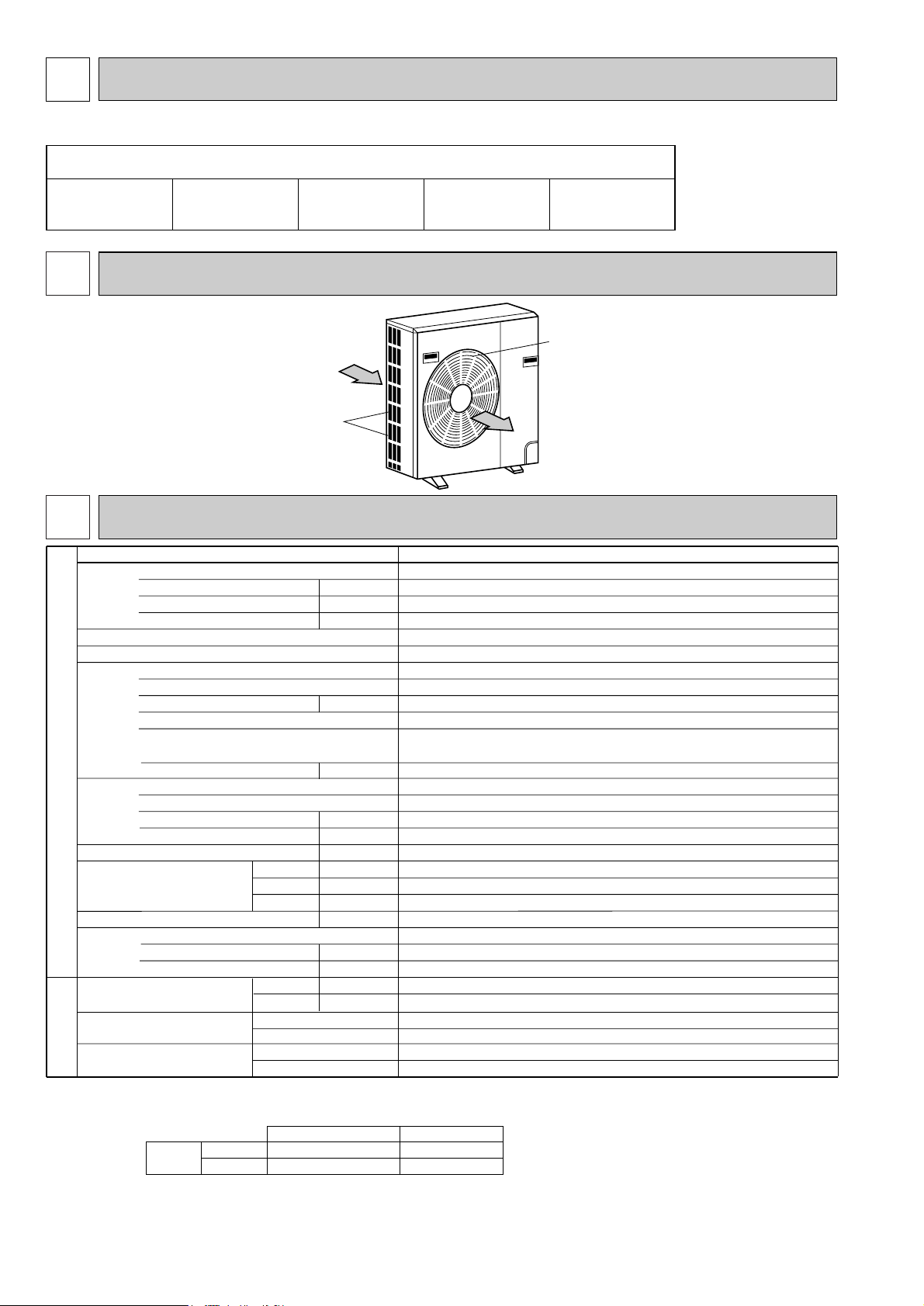
2 PART NAMES AND FUNCTIONS
●Outdoor Unit
PU-3VJC.UK/PU-3YJC.UK
Air intake
3 SPECIFICATIONS
Service Ref.
Power supply (phase, cycle, voltage)
Input
Running current
Starting current
External finish
Refrigerant control
Compressor
Model
Motor output
Starter type
Protection devices
Cranckcase heater
Heat exchanger
OUTDOOR UNIT
Fan(drive) × No.
Fan motor output
Airflow
Noise level
W
Dimensions
Weight
Refrigerant
Charge
Oil (Model)
Pipe size O.D.
Connection method
PIPING
Between the indoor & outdoor unit
REFRIGERANT
Notes1.Rating Conditions (JIS B8616)
Cooling: Indoor : D.B. 27°C(80°F), D.B. 19°C(66°F) Outdoor : D.B. 35°C(95°F), W.B. 24°C(75°F)
Refigerant piping length (one way) :5m (16ft)
2. Guaranteed operating range
Cooling
3. Above values are as follows.
Indoor Unit 1 phase 220V 50Hz
Outdoor Unit 1 phase 220V 50Hz / 3 phase 380V 50Hz
Upper limit
Lower limit
D
H
Liquid
Gas
Indoor side
Outdoor side
Height difference
Piping length
D.B. 35°C, W.B. 22.5°C
D.B. 21°C, W.B. 15.5°C
Indoor
kW
A
A
kW
W
kW
CMM
dB
mm(in.)
mm(in.)
mm(in.)
kg(lbs)
kg(lbs)
L
mm(in.)
mm(in.)
Outdoor
D.B. 52°C
D.B. 21°C
Single, 50Hz, 220~240V / 3, 50Hz, 380-415V (4wires)
Internal thermostat,
HP switch , LP switch
Air outlet
PU-3VJC.UK / PU-3YJC.UK
3.18
15.1 / 5.7
54 /34
Munsell 5Y 7/1
Capillary tube
Hermetic
NH52VNDT / NH52YDAT
2.2 / 2.4
Line start
thermal switch, reversed-phase protector,
/
HPswitch, LP switch, thermal relay
32
Plate fin coil
Propeller (direct)
0.085
50
52
870(34-1/4)
295+24 (11-5/8 +1)
850(33-7/16)
73(161)
R-22
2.8(6.2)
1.6 (MS32)
9.52 (3/8)
15.88(5/8)
Flared
Flared
Max. 20m
Max. 30m
2
Page 3
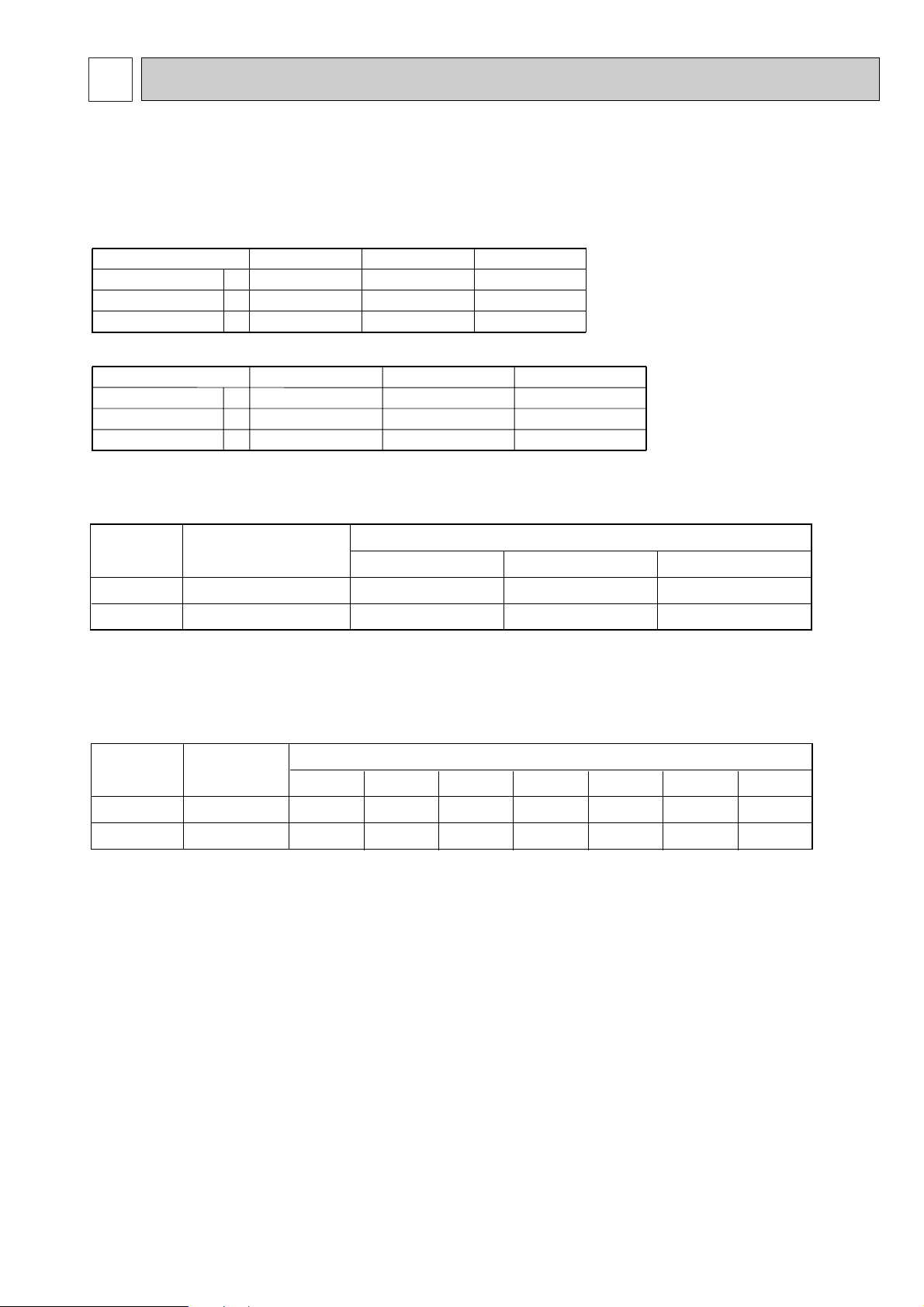
4 DATA
Power supply (1 phase)
Current
Input
Starting current
A
A
kW
Power supply (3 phase)
Current
Input
Starting current
A
A
kW
220V 50Hz
230V 50Hz
240V 50Hz
15.1
3.18
54
14.4
3.19
56
13.9
3.20
58
380/220V 50Hz
5.7
3.18
34
5.4
3.19
36
5.3
3.20
37
400/230V 50Hz 415/240V 50Hz
PU-3VJC.UK
PU-3YJC.UK
Compressor
Winding resistance("). at 20:
R-C/U-V S-C/V-W W-U
NH52VNDT
NH52YDAT
0.83
3.68
2.03
3.68
—
3.68
PU-3VJC.UK
PU-3YJC.UK
Outdoor unit
Service Ref.
Outdoor unit
precharged (kg)
(up to 20m)
Refrigerant piping length (one way)
20m (66ft)
25m (82ft)
30m (98ft)
35m (115ft) 40m (131ft) 45m (148ft)50m (164ft)
2.8
2.8
0
0
0.06(0.13)
0.06(0.13)
0.12(0.26)
0.12(0.26)
—
—
—
—
—
—
—
—
PU-3VJC.UK
PU-3YJC.UK
Outdoor unit
Service Ref.
1. ELECTRICAL SPECIFICATIONS
Rating conditions
●JIS B 8616
2. COMPRESSOR TECHNICAL DATA
Indoor : D.B. 27˚C(80˚F), W.B. 19˚C(66˚F)
Outdoor : D.B. 35˚C(95˚F), W.B. 24˚C(75˚F)
3. ADDITIONAL REFRIGERANT CHARGE (R-22
……
kg (lbs))
3
Page 4
100 10
1000For 10 units or less
200
Outdoor Unit-necessary surrounding clearance
(Concentrated installation)
The upper side must be open.
Outdoor Unit-necessary surrounding clearance
200
10
10
10
Note:Allow adequate
upper clearance
150
500
500
Service space
Front opening
Handle
for moving
138
95
Rear piping hole
23
33
Rear fresh
air intake
Side air intake
7 24(1)295(11-5/8)
Outlet guide
installation hole
302
Air intake
Air intake
Air outlet
870(34-1/4)
185
(7-9/32)
185
(7-9/32)
500(19-11/16)
330(13)
362(14-1/4)
1715
39.5 27.5
Terminal block for indoor and outdoor unit connection
Terminal block for power line with ground terminal
Handle for moving
179 524
441
337
352
403
553
850(33-7/16)
40 60524
Service panel
Refrigerant-pipe flared
connection [15.88 (5/8)
Refrigerant-pipe flared
connection [9.52 (3/8)
Knock out hole
for front piping
(refrigerant,drainage
and wiring)
Knock out hole
for front piping
(refrigerant,drainage
and wiring)
R
20
R
2
0
60
120
4553
25 max.
Knock out holes for
power line 2-[27
Standard bolt length
65
Front right piping holes-
detail figures
80
17
42
45
12
R6
104
33
Bottom
piping hole
2-U-shaped
notched
holes
Drain hole
Drain hole
2-12o23 Oval holes
(standard bolt M10)
Handle for moving
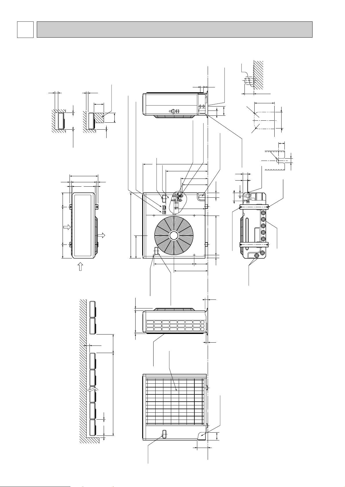
5 OUTLINES AND DIMENSIONS
PU-3VJC.UK / PU-3YJC.UK
Unit : mm (inch)
4
Page 5

6 WIRING DIAGRAM
PU-3VJC.UK
POWER SUPPLY
~/N
220-240V
50Hz
TB1
L
N
GRN/YLW
F3
(5A)
A
TB3
RED
1
1
2
2
WHT
PU-3YJC.UK
POWER SUPPLY
3N~
380/220~415/240V 50Hz
TB1
L1
L2
L3
N
GRN
/YLW
RED
F3
(5A)
YLW
A
TB3
RED
1
1
2
2
WHT
RED
YLW
A2
B
X14
X14
RED
WHT
A1
A1
B
BLK
RED
BLU
52
BLU
52
C
X17X14
BLU
C
A2
ORN
X17X14
22
21
52C
GRY
GRY
GRY
P1
RED
RST
2
1
52C
GRY
ORN
P1
GRY
2
1
WHT
X6
32
31
X6
L1/1
L2/3
L3/5
BLU
L1/1
L3/5
HC
13 14
GRY
52C
X6
BLU
YLW
C
47
A
13
VLT
52C
X6
63H
52C
VLT
52C
47
HC
52C
52C
52C
VLT
52C
26C
14
T1/2
T3/6
GRY
P3P3
YLW
GRY
VLT
P3 P3
X17
63L
WHT
X17
63H
63L
WHT
P2
51C
P2
RED
WHT
C3
WHT
CP
T1/2
T2/4
T3/6
C3
51C
9695
GRY
WHT
CP
BLU
RED
WHT
RED
WHT
BLK
WHT
RED
BLU
C
CP
R
V
49F3
U
W
49F3
MC
MF3
MC
MF3
BLK
C
S
RED
C
49C
BLU
4
RED
2
ORNORN
1
3
WHT
BLU
4
RED
2
ORNORN
1
3
WHT
C3
F3
HC
MC
MF3
TB1
TB3
49C
49F3
52C
63H
63L LOW PRESSURE SWITCH
NOTES: 1. THE DOTTED LINES SHOW FIELD WIRING.
2. TO INDOOR UNIT TERMINAL BLOCK.
CP
C3
F3
HC
MC
MF3
TB1
TB3
26C
47
49F3
51C
52C
63H
63L
NOTES:1.THE DOTTED LINES SHOW FIELD WIRING.
2. TO INDOOR UNIT TERMINAL BLOCK.
COMPRESSOR RUN CAPACITOR
COMPRESSOR PROTECTOR
FAN MOTOR CAPACITOR
FUSE(5A)
CRANKCASE HEATER
COMPRESSOR
FAN MOTOR
TERMINAL BLOCK (POWER SUPPLY)
TERMINAL BLOCK (INDOOR/OUTDOOR CONNECTING LINE)
COMPRESSOR INTERNAL THERMOSTAT
FAN MOTOR INTERNAL THERMOSTAT
COMPRESSOR CONTACTOR
HIGH PRESSURE SWITCH
COMPRESSOR PROTECTOR
FAN MOTOR CAPACITOR
FUSE(5A)
CRANKCASE HEATER
COMPRESSOR
FAN MOTOR
TERMINAL BLOCK (POWER SUPPLY)
TERMINAL BLOCK (CONNECTING WIRES INDOOR/OUTDOOR)
THERMAL SWITCH
ANTI-PHASE PROTECTOR
INTERNAL THERMOSTAT
THERMAL RELAY
COMPRESSOR CONTACTOR
HIGH PRESSURE SWITCH
LOW PRESSURE SWITCH
7 REFRIGERANT SYSTEM DIAGRAM
PU-3VJC.UK / PU-3YJC.UK
High pressure
switch
Strainer
Compressor
Capillary tube
[ ø3.2 oø1.8 o800mm ]
o 2pcs
Discharge pressure regulator
Outdoor heat
exchanger
Strainer
flow of refrigerant
ø15.88
(5/8'')
Strainer
Ball
valve
ø9.52
(3/8'')
Low pressure
switch
Charge
plug
Accumulator
Ball valve
(with service port)
Check
plug
Unit : mm(inch)
5
Page 6

8 DISASSEMBLY PROCEDURE
OUTDOOR UNIT (PU-3VJC.UK)
OPERATING PROCEDURE PHOTOS
1. Removing the electrical parts
(1)
Remove the 5 screws and the top panel. (3 screws in
front and 2 screws in rear
(2)
Remove the screw of the cover panel. To remove the
cover panel, pull it toward you and unhook the catches
from the side panel.
(3)
Remove the screw of the service panel. To remove the
service panel, pull it down toward you and unhook the
catches on the both sides.
)
Photo 1
Photo 2
Compressor
protector
Screws
Top panel
Service panel
Panel cover
Front panel
Capacitor
Contactor
2. Removing the fan motor
(1)
Remove the 3 screws of the front panel. Open the
front panel to a 45-degree angle. Then lift it and
unhook the 3 catches to remove.
(2)
Remove the propeller nut and the propeller.
(3)
Remove the 3 screws and the fan motor.
Disconnect the lead connectors.
Photo 3
Propeller
6
Terminal blockScrews
Motor support
Propeller nut Crankcase heater
Separator support plate
High-pressure protect
Lead
connectors
Valve bed
switch
Page 7

OPERATING PROCEDURE PHOTOS
3. Removing the heat exchanger and the compressor
(1)
Remove the rear panel (2 screws in front, 1 screw on
the side, 3 screws in the rear). Remove the valve bed,
and open the rear panel to the rear to remove.
NOTE :
All panels are fixed by catches, and must be removed by
shifting up and down.
(2)
Remove the 4 screws of the right side panel and
remove the right side panel.
(3)
Remove the 3 screws of the rear guard and remove the
rear guard.
(4)
Remove the 4 screws of the separator support plate
and remove the separator support.
(5)
Remove the 2 screws of the motor support and remove
the motor support.
(6)
Remove the 5 screws of the valve bed.
The valve bed is fixed by the catches on the right and
left sides.
Lift it to remove.
(7)
Remove the electrical parts box.
Disconnect the connectors from the high pressure
switch, crank case heater and fan motor lead.
(8)
Remove the 2 screws of the separator and remove the
separator.
(9)
Remove the 2 screws of the heat exchanger and
remove the heat exchanger.
Detach the welded point of pipe.
)
(
Remove the 3 nuts of the compressor and remove the
10
compressor.
Detach the welded points of the compressor suction
pipe and discharge pipe.
Photo 4
Screws
Screws
Photo 5
Heat exchanger
Accumulator
Photo 6
Charge plug
Valve bed
Ball valve
Compressor
7
Page 8

9 PARTS LIST
FUNCTIONALPARTS
PU-3VJC.UK / PU-3YJC.UK
3
5
4
6
7
(for PU-3YJC)
23
9
PU-3VJC.UK
8
22
20
4
19 3 89
18
2
21
Part No. Part Name Specification
No.
1
S70 020 763
2
S70 001 115
3
S70 965 282
4
S70 510 239
5
S70 510 241
S70 509 716
6
S70 093 716
7
S70 515 716
S70 616 709
8
S70 A07 708
9
S70 576 255
S70 631 400
10
S70 613 400
11
S70 A04 208
12
S70 965 209
13
S70 A08 440
14
S70 A05 236
15
S70 951 411
16
S70 943 410
17
S70 591 413
18
S70 004 408
19
S70 101 723
20
S70 050 425
21
S70 300 097
22
S70 001 402
23
S70 104 290
24
S70 652 238
1
FAN MOTOR
PROPELLER FAN
COMPRESSOR PROTECTOR
FUSE
FUSE HOLDER
TERMINAL BLOCK (POWER)
TERMINAL BLOCK (POWER)
TERMINAL BLOCK
COMPRESSOR CONTACTOR
COMPRESSOR CONTACTOR
FAN MOTOR CAPACITOR
COMPRESSOR
COMPRESSOR
HIGH PRESSURE SWITCH
LOW PRESSURE SWITCH
ACCUMULATOR
CRANKCASE HEATER
BALL VALVE 5/8
BALL VALVE 3/8
CHARGE PULG
HEAT EXCHANGER
COMPRESSOR RUN CAPACITOR
CAPILLARY TUBE
DOME CAP NUT
DISCHARGE PRESSURE REGULATOR
ANTI PHASE PROTECTOR
THERMAL SWITCH
10
(COMMS)
17
11
24
(for PU-3YJC)
PN6V85-UA
250V 5A
Earth
(L, N,
(L1, L2, L3, N, Earth)
(1, 2)
S-N25EX
MSO-N12KF
3µF 440V
NH52 VNDT
NH52 YDAT
CUT 3.24MPa
CUT 0.05MPa
240V 38W
60µF
ø3.2✕ø1.8✕800mm
M8
)
12
13
17
16
15
14
PU-3VJC.UK
Q,ty/set
1
1
1
1
1
1
1
1
1
1
1
1
1
1
1
1
2
1
1
1
1
1
PU-3YJC.UK
1
1
1
1
1
1
1
1
1
1
1
1
1
1
1
1
2
1
1
1
1
1
1
5
7
Remarks
6
Wining
Diagram
Symbol
MF3
CP
F3
TB1
TB1
TB3
52C
52C
C3
MC
MC
63H
63L
HC
C
47
26C
Recom-
mended
Q,ty
Price
Unit
Amount
8
Page 9

STRUCTURAL PARTS
S70 020 641
S70 001 673
S70 001 668
S70 001 675
S70 A00 655
S70 001 661
S70 030 662
S70 001 699
S70 002 699
S70 030 682
S70 020 658
S70 030 698
S70 001 130
S70 001 686
TOP PANEL
SCREW
FRONT PANEL
FAN GUARD
HANDLE
SERVICE PANEL
SIDE PANEL
LABEL (MITSUBISHI)
LABEL (BRAND)
REAR PANEL
COVER PANEL
REAR GUARD
MOTOR SUPPORT
BASE
1
13
1
1
3
1
1
1
1
1
1
1
1
1
(5✕10)
Part No. Part Name
SpecificationNo.
Q,ty/set
Wiring
Diagram
Symbol
Recom-
mended
Q,ty
Price
Unit
Amount
Remarks
(Drawing No.)
PU-3
VJC.UK , YJC.UK
1
2
3
4
5
6
7
8
9
10
11
12
13
14
PU-3VJC.UK / PU-3YJC.UK
1 122
8105
7
3
5
4
14 13 6911
9
Page 10

10 OPTIONALPARTS
AIR OUTLET GUIDE
This guide is needed for changing the direction of the outdoor unit’s air discharge upward or downward.
Part No. PAC-292SG
537
538
7
7
5247
524
7
4oø6 hole
72
Unit : mm
10
Page 11

Page 12

HEAD OFFICE MITSUBISHI DENKI BLDG.MARUNOUCHI TOKYO100-8310 TELEX J24532 CABLE MELCO TOKYO
CCopyright 1999 MITSUBISHI ELECTRIC ENGINEERING CO.,LTD.
Issued in Dec. 1999. No. OC202 242 New publication, effective Dec.1999
Printed in Japan. Specifications subject to change without notice.
 Loading...