

Mitsubishi Electric PKFY-P, NKMU-E Installation Manual
Air-Conditioners For Building Application
INDOOR UNIT
PKFY-P·NKMU-E
For use with the R410A & R22
A utiliser avec le R410A et le R22
Para utilizar con el R410A y el R22
INSTALLATION MANUAL
For safe and correct use, read this manual and the outdoor unit installation manual thoroughly before installing
the air-conditioner unit.
FOR INSTALLER
English
MANUEL D’INSTALLATION
Avant d’installer le climatiseur, lire attentivement ce manuel, ainsi que le manuel d’installation de l’appareil
extérieur pour une utilisation sûre et correct.
POUR L’INSTALLATEUR
Français
MANUAL DE INSTALACIÓN
Para un uso correcto y seguro, lea detalladamente este manual y el manual de instalación de la unidad exterior
antes de instalar la unidad de aire acondicionado.
PARA EL INSTALADOR
Español

2
► Before installing the unit, make sure you read all the “Safety
precautions”.
► Please report to your supply authority or obtain their consent before
connecting this equipment to the power supply system.
Warning:
Describes precautions that must be observed to prevent danger of injury or
death to the user.
Caution:
Describes precautions that must be observed to prevent damage to the unit.
After installation work has been completed, explain the “Safety Precautions,” use,
and maintenance of the unit to the customer according to the information in the
Operation Manual and perform the test run to ensure normal operation. Both the
Installation Manual and Operation Manual must be given to the user for keeping.
These manuals must be passed on to subsequent users.
Contents
Warning:
• Ask the dealer or an authorized technician to install the air conditioner.
• Install the unit at a place that can withstand its weight.
• Use the specified cables for wiring.
• Use only accessories authorized by Mitsubishi Electric and ask the dealer
or an authorized technician to install them.
• Do not touch the heat exchanger fins.
• Install the air conditioner according to this Installation Manual.
• Have all electric work done by a licensed electrician according to local
regulations.
• If the air conditioner is installed in a small room, measures must be taken
to prevent the refrigerant concentration from exceeding the safety limit
even if the refrigerant should leak.
• The cut face punched parts may cause injury by cut, etc. The installers are
requested to wear protective equipement such as gloves, etc.
• When installing or relocating, or servicing the air conditioner, use only the
specified refrigerant (R410A) to charge the refrigerant lines. Do not mix it
with any other refrigerant and do not allow air to remain in the lines.
If air is mixed with the refrigerant, then it can be the cause of abnormal
high pressure in the refrigerant line, and may result in an explosion and
other hazards.
The use of any refrigerant other than that specified for the system will
cause mechanical failure or system malfunction or unit breakdown. In the
worst case, this could lead to a serious impediment to securing product
safety.
1. Safety precautions
: Indicates an action that must be avoided.
: Indicates that important instructions must be followed.
: Indicates a part which must be grounded.
: Indicates that caution should be taken with rotating parts.
: Indicates that the main power switch must be turned off before servicing.
: Beware of electric shock.
: Beware of hot surface.
ELV
: At servicing, please shut down the power supply for both the Indoor and
Outdoor Unit.
Warning:
Carefully read the labels affixed to the main unit.
Caution:
• Do not use the existing refrigerant piping, when use R410A refrigerant.
• Use ester oil, either oil or alkylbenzene (small amount) as the refrigerator
oil to coat flares and flange connections, when use R410A refrigerant.
• Do not use the air conditioner where food, pets, plants, precision
instruments, or artwork are kept.
• Do not use the air conditioner in special environments.
• Ground the unit.
• Install an leak molded case circuit braker, as required.
• Use power line cables of sufficient current carrying capacity and rating.
• Use only a molded case circuit braker and fuse of the specified capacity.
• Do not touch the switches with wet fingers.
• Do not touch the refrigerant pipes during and immediately after operation.
• Do not operate the air conditioner with the panels and guards removed.
• Do not turn off the power immediately after stopping operation.
1. Safety precautions .............................................................................................
2
2. Installation location ............................................................................................
3
3. Installing the indoor unit ....................................................................................
3
4. Installing the refrigerant piping ..........................................................................
7
5. Drainage piping work .........................................................................................
9
6. Electrical work .................................................................................................
10
7. Test run (Fig. 7-1) ............................................................................................
11
3
2. Installation location
3. Installing the indoor unit
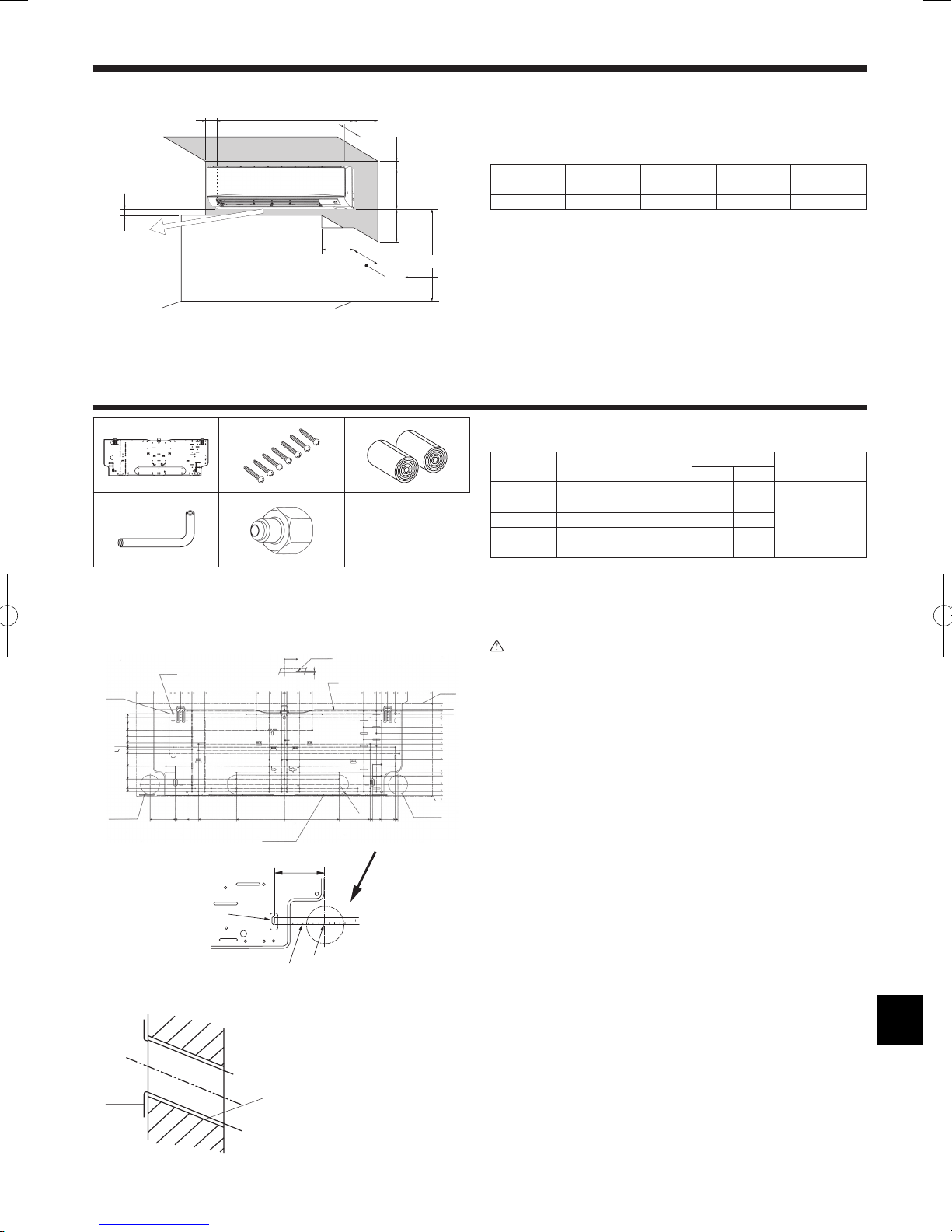
3.1. Check the indoor unit accessories (Fig. 3-1)
The indoor unit should be supplied with the following accessories.
PART NUMBER
ACCESSORY
QUANTITY
LOCATION OF SETTING
P24 P30
1
Mount board 1 1
Fix at the back of the unit
2
Tapping screw 4 × 25
7 7
3
Felt tape 2 2
4
L-shaped connection pipe 1 1
5
Charge nut 1 1
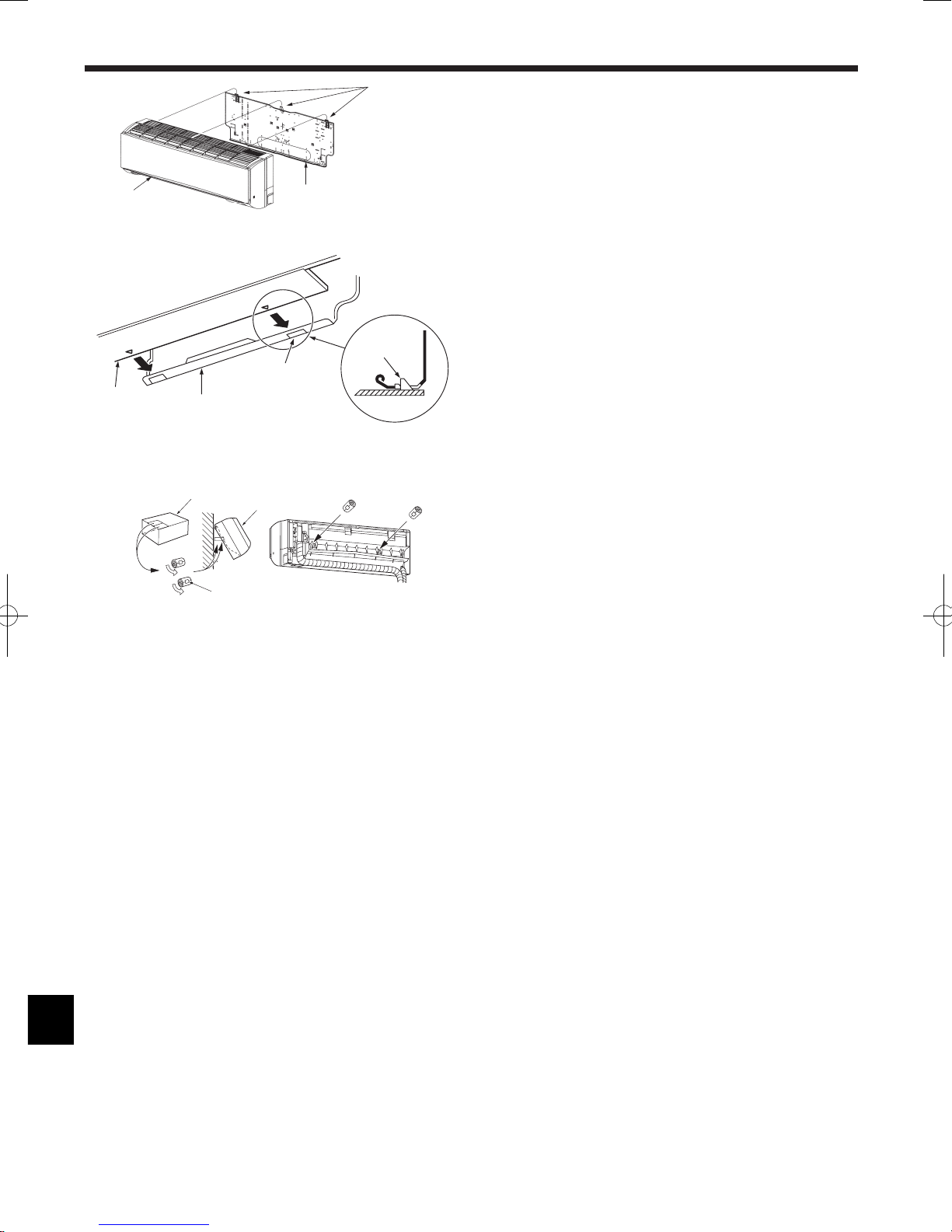
3.2. Installing the wall mounting fixture
3.2.1. Setting the wall mounting fixture and piping positions
► Using the wall mounting fixture, determine the unit’s installation position
and the locations of the piping holes to be drilled.
Warning:
Before drilling a hole in the wall, you must consult the building contractor.
PKFY-P·NKMU-E (Fig. 3-2)
AMount board 1
BIndoor unit
CBottom left rear pipe hole (ø75-ø80 mm, 2-61/64~3-5/32 inch)
DBottom right rear pipe hole (ø75-ø80 mm, 2-61/64~3-5/32 inch)
EKnockout hole for left rear hole
FBolt hole (4-ø9 mm, 23/64 inch hole)
GCenter measurement hole (ø2.5 mm, 3/32 inch hole)
HTapping hole (75-ø5.1 mm, 13/64 inch hole)
IHole centre
JAlign the scale with the line.
KInsert scale.
3.2.2. Drilling the piping hole (Fig. 3-3)
► Use a core drill to make a hole of 75-80 mm, 2-61/64~3-5/32 inch diameter
in the wall in the piping direction, at the position shown in the diagram to
the left.
► The hole should incline so that the outside opening is lower than the
inside opening.
► Insert a sleeve (with a 75 mm, 2-61/64 inch diameter and purchased
locally) through the hole.
Note:
The purpose of the hole’s inclination is to promote drain flow.
Fig. 2-1
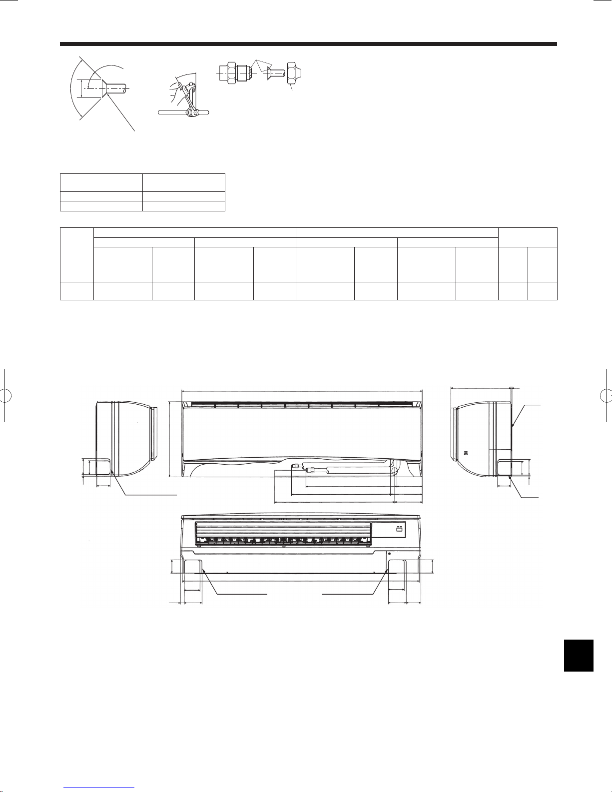
2.1. Outline dimensions (Indoor unit) (Fig. 2-1)
Select a proper position allowing the following clearances for installation and
maintenance.
PKFY-P·NKMU-E
(mm, inch)
A B C D E
Min. 100.5 Min. 52.3 Min. 48 Min. 250 Min. 220
Min. 3-31/32 Min. 2-1/16 Min. 1-7/8 Min. 9-27/32 Min. 8-21/32
FAir outlet: Do not place an obstacle within 1500 mm, 59-1/16 inch of the air outlet.
GFloor surface
HFurnishing
IWhen the projection dimension of a curtain rail or the like from the wall exceeds 60 mm,
2-23/64 inch extra distance should be taken because the fan air current may create a short
cycle.
J1800 mm, 70-7/8 inch or greater from the floor surface (for high location mounting)
K108 mm, 4-1/4 inch or greater with left or rear left piping
LMinimum 7 mm, 9/32 inch
Fig. 3-1
PKFY-P·NKMU-E
Fig. 3-2
31/32
0
1/2
1-15/32
2-15/32
3-7/16
4-1/8
5-3/32
6-9/16
8-17/32
9-1/32
10-13/32
11-1/2
12-5/32
12-1/4
2-1/8
23-1/32
18-5/16
17-7/8
17-9/32
16-3/32
15-1/8
14-11/32
12-3/8
4-11/32
2-1/8
0
2-3/8
13/32
13/32
2-3/8
4-11/32
12-3/8
14-11/32
15-1/8
16-3/32
17-9/32
17-7/8
20-3/8
23-1/32
20-7/8
17-9/32
15-1/8
7-7/16
0
8-17/32
R1-15/
32
13-3/4
15-1/8
17-9/32
5/8
0
31/32
1-31/32
2-15/16
3-15/16
4-19/32
4-29/32
5-19/32
7-9/16
9-17/32
11
11-1/2
A
B
C
D
F
G
D
E
1/8
1-1/4
1/2
A
K
J
I
3-15/16
(inch)
PKFY-P·NKMU-E
Fig. 3-3
A
C
D
E
B
ASleeve
BHole
C(Indoors)
DWall
E(Outdoors)
*
G
F
A
B
1170
46-1/16
365
14-3/8
H
E
J
L
I
D
C
295
11
-5/8
K
(mm)
(inch)
1 2 3
4 5
4
3. Installing the indoor unit
PKFY-P·NKMU-E
Fig. 3-7Fig. 3-6
A A
Fig. 3-8
A
B
D
C
E
Fig. 3-10Fig. 3-9
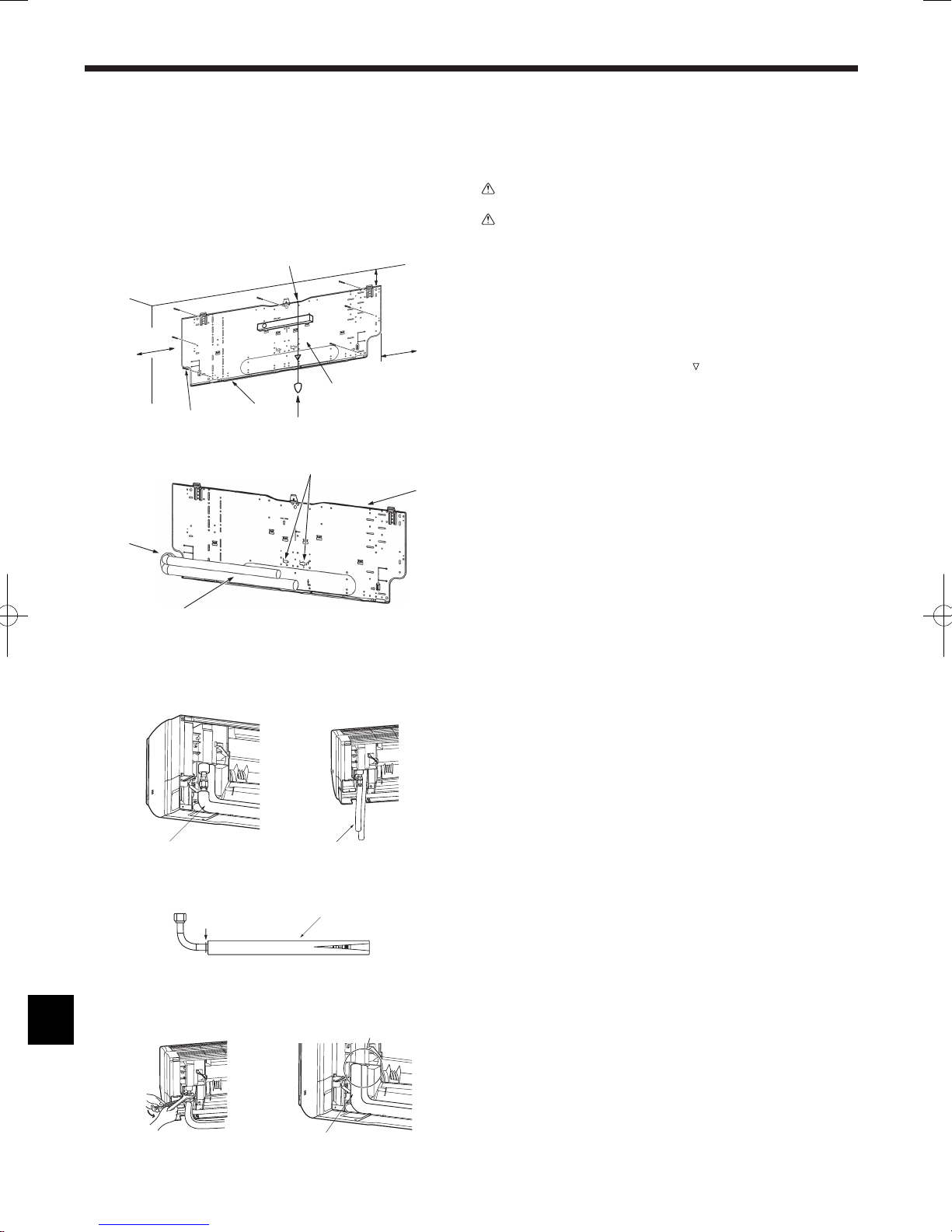
3.2.3. Installing the wall mounting fixture
► Since the indoor unit weighs near 21 kg, 46 lbs selection of the mounting
location requires thorough consideration. If the wall does not seem to be
strong enough, reinforce it with boards or beams before installation.
► The mounting fixture must be secured at both ends and at the centre, if
possible. Never fix it at a single spot or in any nonsymetrical way.
(If possible, secure the fixture at all the positions marked with a bold
arrow.)
Warning:
If possible, secure the fixture at all positions indicated with a bold arrow.
Caution:
• The unit body must be mounted horizontally.
• Fastenattheholesmarkedwith▲asshownbythearrows.
PKFY-P·NKMU-E (Fig. 3-4)
AMin. 120 mm, 4-11/16 inch
BMin. 220 mm, 8-11/16 inch
CMin. 70 mm, 2-3/4 inch
DFixing screws (4 × 25) 2
ELevel
FFasten a thread to the hole.
G
Place the level against the horizontal reference line of the mount board and mount so that it is
level. Hang a weight from the thread and align with EPK of the mount board to permit leveling.
HWeight
IMount board 1
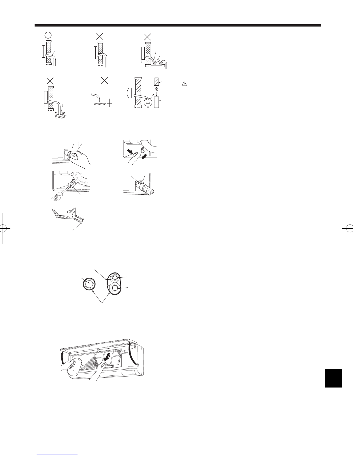
3.3. When embedding pipes into the wall (Fig. 3-5)
• The pipes are on the bottom left.
• When the cooling pipe, drain pipes internal/external connection lines etc are to
be embedded into the wall in advance, the extruding pipes etc, may have to be
bent and have their length modified to suit the unit.
• Use marking on the mount board as a reference when adjusting the length of the
embedded cooling pipe.
• During construction, give the length of the extruding pipes etc some leeway.
AMount board 1
BReference marking for flare connection
CThrough hole
DOn-site piping
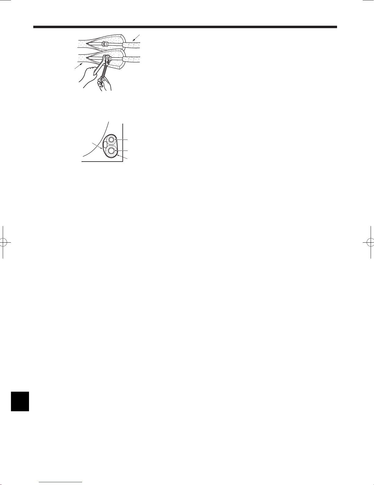
3.4. Preparing the indoor unit
* Check beforehand because the preparatory work will differ depending on the
exiting direction of the piping.
* When bending the piping, bend gradually while maintaining the base of the
piping exiting portion. (Abrupt bending will cause misshaping of the piping.)
PKFY-P·NKMU-E
Attachment of L-shaped connection pipe 4
Right, left and rear piping (Fig. 3-6)
1. Remove the flare nut and cap of the indoor unit. (Gas pipe only)
2. Apply refrigerating machine oil to the flare sheet surface. (Preparation on
location)
3. Facing the direction in which the L-shaped connection pipe
4 will be removed,
make a quick connection to the indoor unit flare connection opening.
4. Tighten the flare nut using a double open-end wrench. (Fig. 3-9)
Tightening force: 68 to 82 N·m, 49~59 ft·lbs
5. Attach the charge nut
5 to the liquid pipe side joint portion, and check for
leakage of the L-shaped connection pipe 4 connection portion.
Remove the charge nut
5 after completion of the work.
Tightening force: 34 to 42 N·m, 25~30 ft·lbs
6. Cover the flare connection portion with the pipe cover of the L-shaped
connection pipe 4 so that it is not exposed. (Fig. 3-10)
AL-shaped connection pipe 4
BCut-off position (Straight pipe portion)
CTightening direction
DCover with pipe cover
E Cover the flare nut connection portion with the pipe cover.
Lower piping (Fig. 3-7)
1. Cut L-shaped connection pipe 4 at the position indicated in (Fig. 3-8).
2. Insert the flare nut that was removed earlier onto the straight pipe side of the cut
L-shaped connection pipe 4 and then flare the end of the pipe.
3. Remove the flare nut and cap of the indoor unit. (Gas pipe only)
4. Apply refrigerating machine oil to the flare sheet surface. (Preparation on
location)
5. Quickly connect the L-shaped connection pipe
4 that has been processed as
described in part 2) to the indoor unit flare connection opening.
6. Tighten the flare nut using a double open-end wrench. (Fig. 3-9)
Tightening force: 68 to 82 N·m, 49~59 ft·lbs
7. Attach the charge nut
5 to the liquid pipe side joint portion, and check for
leakage of the L-shaped connection pipe 4 connection portion.
Remove the charge nut
5 after completion of the work.
Tightening force: 34 to 42 N·m, 25~30 ft·lbs
8. Cover the flare connection portion with the pipe cover of the L-shaped
connection pipe 4 so that it is not exposed. (Fig. 3-10)
PKFY-P·NKMU-E
Fig. 3-4
A
B
C
D
I
G
F
H
E
Fig. 3-5
B
A
C
D
5
3. Installing the indoor unit
Fig. 3-11
B
A
C
E
D
Leakage check of the L-shaped connection pipe connection portion
1. Attach the charge nut 5 to the liquid pipe side joint portion.
Tightening force: 34 to 42 N·m, 25~30 ft·lbs
2. Pressurize by filling with nitrogen gas from the charge nut.
Do not pressurize to the current constant pressure all at once. Pressurize
gradually.
1) Pressurize to 0.5 MPa, 73 PSIB wait five minutes, and make sure the
pressure does not decrease.
2) Pressurize to 1.5 MPa, 218 PSIB wait five minutes, and make sure the
pressure does not decrease.
3) Pressurize to 4.15 MPa, 606 PSIB and measure the surrounding temperature
and refrigerant pressure.
3. If the specified pressure holds for about one day and does not decrease, the
pipes have passed the test and there are no leaks.
• If the surrounding temperature changes by 1°C, 33.8°F the pressure will
change by about 0.01 MPa, 1.5 PSIB. Make the necessary corrections.
4. If the pressure decreases in steps (2) or (3), there is a gas leak. Look for the
source of the gas leak.
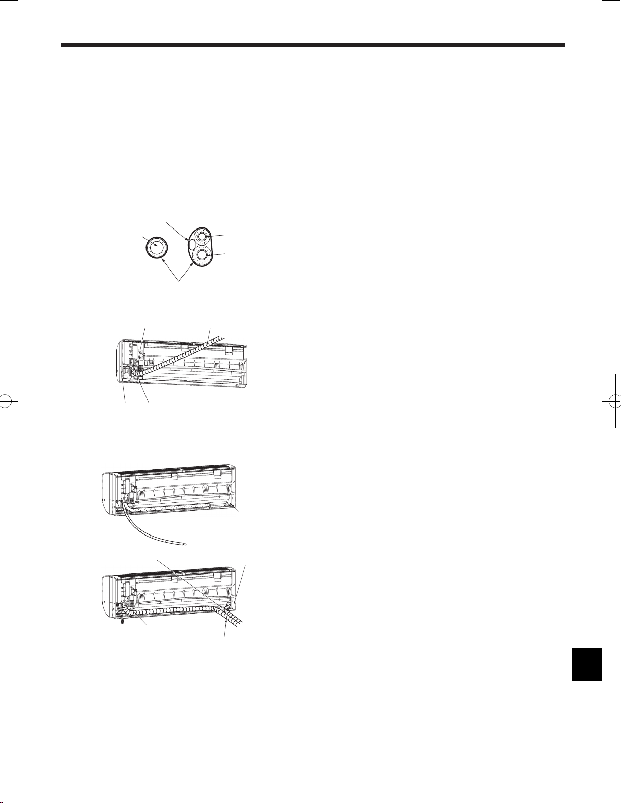
Extraction and processing of the piping and wiring (Fig. 3-11)
1. Connection of indoor/outdoor wiring See page. 8.
2. Wrap the felt tape
3 in the range of the refrigerant piping and drain hose which
will be housed within the piping space of the indoor unit.
• Wrap the felt tape
3 securely from the base for each of the refrigerant piping
and the drain hose.
• Overlap the felt tape
3 at one-half of the tape width.
• Fasten the end portion of the wrapping with vinyl tape.
ALiquid pipe
BGas pipe
CIndoor/outdoor connection cable
DDrain hose
EFelt tape 3
3. Be careful that the drain hose is not raised, and that contact is not made with the
indoor unit box body.
Do not pull the drain hose forcefully because it might come out.
Rear, right and lower piping (Fig. 3-12)
1) Be careful that the drain hose is not raised, and that contact is not made with
the indoor unit box body.
Arrange the drain hose at the underside of the piping and wrap it with felt
tape 3.
2) Securely wrap the felt tape
3 starting from the base. (Overlap the felt tape at
one-half of the tape width.)
ACut off for right piping.
BCut off for lower piping.
Left and left rear piping (Fig. 3-13)
4. Drain hose replacement See 6. Drainage piping work
Be sure to replace the drain hose and the drain cap for the left and rear left
piping. Dripping may occur if you forget to install or fail to replace these parts.
CDrain cap
1) Be careful that the drain hose is not raised, and that contact is not made with
the indoor unit box body.
2) Securely wrap the felt tape
3 starting from the base. (Overlap the felt tape at
one-half of the tape width.)
3) Fasten the end portion of the felt tape
3 with vinyl tape.
DCut off for left piping.
Fig. 3-12
B
A
1
)
2
)
Fig. 3-13
C
D
1
)
3
)
2
)
6
3.5. Mounting the indoor unit
1. Affix the mount board 1 to the wall.
2. Hang the indoor unit on the hook positioned on the upper part of the mount
board.
Rear, right and lower piping (Fig. 3-14)
3. While inserting the refrigerant piping and drain hose into the wall penetration
hole (penetration sleeve), hang the top of the indoor unit to the mount board 1.
4. Move the indoor unit to the left and right, and verify that the indoor unit is hung
securely.
5. Fasten by pushing the bottom part of the indoor unit onto the mount board
1.
(Fig. 3-15)
* Check that the knobs on the bottom of the indoor unit are securely hooked into
the mount board 1.
6. After installation, be sure to check that the indoor unit is installed level.
AMount board 1
BIndoor unit
CHook
Dsquare hole
Left and left rear piping (Fig. 3-16)
3. While inserting the drain hose into the wall penetration hole (penetration sleeve),
hang the top of the indoor unit to the mount board 1.
Giving consideration to the piping storage, move the unit all the way to the left
side, then cut part of the packaging carton and wrap into a cylindrical form as
illustrated in the diagram. Hook this to the rear surface rib as a spacer, and raise
the indoor unit.
4. Connect the refrigerant piping with the site-side refrigerant piping.
5. Fasten by pushing the bottom part of the indoor unit onto the mount board
1.
* Check that the knobs on the bottom of the indoor unit are securely hooked into
the mount board 1.
6. After installation, be sure to check that the indoor unit is installed level.
A Indoor unit
B Packaging carton
C Cut off
D Wrap into a cylindrical form
E Fasten with tape
3. Installing the indoor unit
Fig. 3-14
Fig. 3-15
Fig. 3-16
B
A
C
D
A
C
B
C
B
A
E
D
PKFY-P·NKMU-E
7
4. Installing the refrigerant piping
90°±0.5°
øA
R0.4~R0.8
A
45±2°
B
C
D
Fig. 4-1
4.1. Connecting pipes (Fig. 4-1)
• When commercially available copper pipes are used, wrap liquid and gas pipes
with commercially available insulation materials (heat-resistant to 100 °C, 212 °F
or more, thickness of 12 mm, 1/2 inch or more).
• The indoor parts of the drain pipe should be wrapped with polyethylene foam
insulation materials (specific gravity of 0.03, thickness of 9 mm, 23/64 inch or
more).
• Apply thin layer of refrigerant oil to pipe and joint seating surface before
tightening flare nut.
• Use two wrenches to tighten piping connections.
• Use refrigerant piping insulation provided to insulate indoor unit connections.
Insulate carefully.
A Flare cutting dimensions
Copper pipe O.D.
(mm, inch)
Flare dimensions
øA dimensions (mm, inch)
ø9.52, 3/8” 12.8 - 13.2, 1/2 - 33/64
ø15.88, 5/8” 19.3 - 19.7, 49/64 - 25/32
B Refrigerant pipe sizes & Flare nut tightening torque
R22 R410A
Flare nut O.D.
Liquid pipe Gas pipe Liquid pipe Gas pipe
Pipe size O.D.
(mm, inch)
Tightening
torque.
(N·m, ft·lbs)
Pipe size O.D.
(mm, inch)
Tightening
torque.
(N·m, ft·lbs)
Pipe size O.D.
(mm, inch)
Tightening
torque.
(N·m, ft·lbs)
Pipe size O.D.
(mm, inch)
Tightening
torque.
(N·m, ft·lbs)
Liquid
pipe
(mm,
inch)
Gas
pipe
(mm,
inch)
P24
P30
ODø9.52
3/8”
34 - 42
25 - 30
ODø15.88
5/8”
68 - 82
49 - 59
ODø9.52
3/8”
34 - 42
25 - 30
ODø15.88
5/8”
68 - 82
49 - 59
22
7/8
29
1-9/64
C Do not apply refrigerating machine oil to the screw portions.
(This will make the flare nuts more apt to loosen.)
DBe certain to use the flare nuts that are attached to the main unit.
(Use of commercially-available products may result in cracking.)
E Apply refrigerating machine oil over the entire flare seat surface.
Fig. 4-2
PKFY-P·NKMU-E
4.2. Positioning refrigerant and drain piping (Fig. 4-2)
PKFY-P·NKMU-E
AGas pipe * Indicates the condition with accessories mounted.
BLiquid pipe
CDrain hose
DLeft-side piping knockout hole
ERight-side piping knockout hole
FLower piping knockout hole
G Mount board 1
D
2-9/16
3-1/325/16
2-5/8
14-3/8
46-1/16
17-15/32 (A)* 4-27/32
18-31/32 (B)
6-1/16
23-1/32 (C)
45-15/32
2-9/16
2-9/16
3-1/32
3-7/16
F F
3-1/32
3-7/16 2-51/6413/32
5-9/32
11-5/8 3/16
2-9/16
2-5/8
3-1/32
5/16
G
E
(inch)
8
4. Installing the refrigerant piping
Fig. 4-4
PKFY-P·NKMU-E
B
A
D
C
4.3. Refrigerant piping (Fig. 4-3)
Indoor unit
1. Remove the flare nut and cap of the indoor unit.
2. Make a flare for the liquid pipe and gas pipe and apply refrigerating machine oil
(available from your local supplier) to the flare sheet surface.
3. Quickly connect the on site cooling pipes to the unit.
4. Wrap the pipe cover that is attached to the gas pipe and make sure that the
connection join is not visible.
5. Wrap the pipe cover of the unit’s liquid pipe and make sure that it covers the
insulation material of the on site liquid pipe.
6. The portion where the insulation material is joined is sealed by taping.
ASite-side refrigerant piping
BUnit side refrigerant piping
4.3.1. Storing in the piping space of the unit (Fig. 4-4)
1. Wrap the supplied felt tape in the range of the refrigerant piping which will be
housed within the piping space of the unit to prevent dripping.
2. Overlap the felt tape at one-half of the tape width.
3. Fasten the end portion of the wrapping with vinyl tape, etc.
AGas pipe
B Liquid pipe
C Indoor/outdoor connection cable
D Felt tape 3
Fig. 4-3
B
A
9
Fig. 5-1
5. Drainage piping work
5.1. Drainage piping work (Fig. 5-1)
• Drain pipes should have an inclination of 1/100 or more.
• For extension of the drain pipe, use a soft hose (inner dia. 15 mm, 19/32 inch)
available on the market or hard vinyl chloride pipe (VP-16/O.D. ø22 mm,
ø55/64 inch PVC TUBE). Make sure that there is no water leakage from the
connections.
• Do not put the drain piping directly in a drainage ditch where sulphuric gas may
be generated.
• When piping has been completed, check that water flows from the end of the
drain pipe.
Caution:
The drain pipe should be installed according to this Installation Manual to
ensure correct drainage. Thermal insulation of the drain pipes is necessary
to prevent condensation. If the drain pipes are not properly installed and
insulated, condensation may drip on the ceiling, floor or other possessions.
AInclined downwards
BMust be lower than outlet point
CWater leakage
DTrapped drainage
EAir
FWavy
GThe end of drain pipe is under water.
HDrainage ditch
I 5 cm, 13/64 inch or less between the end of drain pipe and the ground.
JDrain hose
KSoft PVC hose (Inside diameter 15 mm, 19/32 inch)
or
Hard PVC pipe (VP-16)
* Bond with PVC type adhesive
Preparing left and left rear piping (Fig. 5-2)
1Remove the drain cap.
• Remove the drain cap by holding the bit that sticks out at the end of the pipe and
pulling.
ADrain cap
2Remove the drain hose.
• Remove the drain hose by holding on to the base of the hose
a (shown by
arrow) and pulling towards yourself b.
3Insert the drain cap.
• Insert a screwdriver etc into the hole at the end of the pipe and be sure to push
to the base of the drain cap.
4Insert the drain hose.
• Push the drain hose until it is at the base of the drain box connection outlet.
• Please make sure the drain hose hook is fastened properly over the extruding
drain box connection outlet.
BHooks
Storing in the piping space of the indoor unit (Fig. 5-3)
* When the drain hose will be routed indoors, be sure to wrap it with commercially
available insulation.
* Gather the drain hose and the refrigerant piping together and wrap them with the
supplied felt tape 3.
* Overlap the felt tape
3 at one-half of the tape width.
* Fasten the end portion of the wrapping with vinyl tape, etc.
AGas pipe
BLiquid pipe
CDrain hose
DIndoor/outdoor connection wiring
EFelt tape 3
Check of drainage (Fig. 5-4)
1. Open the front grille and remove the filter.
2. Facing the fins of the heat exchanger, slowly fill with water.
3. After the drainage check, attach the filter and close the grille.
A
B
C
E
D
C
F
C
G
H
I
A
A
1
3
Fig. 5-2
Fig. 5-3
Fig. 5-4
A
B
D
E
C
J
K
PKFY-P·NKMU-E
a
b
A
B
2
4
10
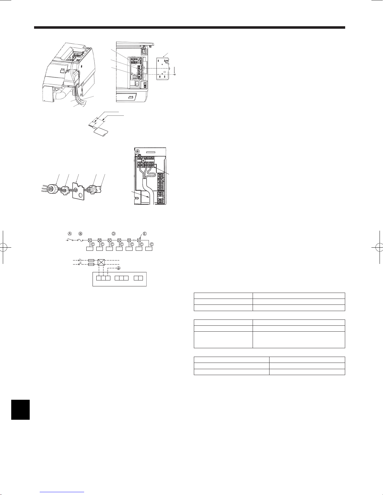
6. Electrical work
6.1. Indoor unit
PKFY-P·NKMU-E (Fig. 6-1)
Connection can be made without removing the front panel.
1. Open the front grille, remove the screw (1 piece), and remove the electrical
parts cover.
2. Securely connect each wire to the terminal board.
* In consideration of servicing, provide extra length for each of the wires.
* Take care when using strand wires, because beards may cause the wiring to
short out.
3. Install the parts that were removed back to their original condition.
4. Fasten each of the wires with the clamp under the electrical parts box.
AElactrical box cover
BFixing screw
DMA remote control terminal board: (1, 2) do not have polarity
ETransmission terminal board: (M1, M2, S) do not have polarity
FPower supply terminal board: (L1, L2, GR).
GLead
HGround wire connection portion: Connect the ground wire in the direction illustrated in the
diagram.
JMA remote control cable
KTransmission cable
LPower supply cable
MConduit plate
NBush (purchased locally)
OLock nut (purchased locally)
PConnector (purchased locally)
QConduit (purchased locally)
6.2. Power supply wiring
• Power supply codes of appliance shall not be lighter than design 245 IEC 53 or
227 IEC 53.
• Install an earth line longer than other cables.
• A switch with at least 3 mm, 1/8 inch contact separation in each pole shall be
provided by the air conditioner installation.
Power cable size : more than 1.5mm2 (AWG16)
[Fig. 6-2]
ASwitch 16 A
BOvercurrent protection 16 A
CIndoor unit
DTotal operating current be less than 16 A
EPull box
► Selecting non-fuse breaker (NF) or earth leakage breaker (NV).
For breaker, means shall be provided to ensure disconnection of all active
phase conductors of the supply.
6.3. Types of control cables
1. Wiring transmission cables
Types of transmission cable Shielding wire CVVS or CPEVS
Cable diameter More than 1.25 mm2 (AWG16)
Length Less than 200m, 219 yard
2. M-NET Remote control cables
Types of remote control cable
Shielding wire MVVS
Cable diameter More than 0.5 (AWG20) to 1.25 mm2 (AWG16)
Length Add any portion in excess of 10m, 33 ft to
within the longest allowable transmission cable
length 200m, 219 yard.
3. MA Remote control cables
Types of remote control cable 2-core cable (unshielded)
Cable diameter 0.3 (AWG22) to 1.25 mm2 (AWG16)
Length Less than 200m, 219 yard
PKFY-P·NKMU-E
J
G
L
K
F
E
D
A
B
15/32 inch
2-11/64 inch
J K L
Fig. 6-1
A B E
C
TB2 TB5 TB15
S 1 2
M1
L1L2GR
M2
L1
L2 GR
L
H
QPMN O
Fig. 6-2
 Loading...