

Mitsubishi PKFY-08NAMU-A, PKFY-12NGMU-A, PLFY-20NAMU-A, PKFY-20NFMU-A, PLFY-12NAMU-A Technical & Service Manual
...
SPLIT-TYPE, HEAT PUMP AIR CONDITIONERS
L
I
S
T
E
D
CUS
CITY MULTI Indoor Unit
TECHNICAL & SERVICE MANUAL
No. OC291
CITY MULTI Series
[Models]
PKFY-08NAMU-A
PKFY-12NGMU-A
PKFY-20NFMU-A
PKFY-32NFMU-A
CITY MULTI Series
[Models]
PLFY-12NAMU-A
PLFY-20NAMU-A
PLFY-24NAMU-A
PLFY-32NAMU-A
PLFY-40NAMU-A
Wall Mounted Type
Ceiling Cassettes Type
• Connected outdoor unit is
PURY-80TMU or PURY-100TMU.
CONTENTS
1. PKFY-•MU-A Type ····················OC292-1
2. PLFY-•NAMU-A Type ···············OC290-1


PKFY-08NAMU-A
PKFY-12NGMU-A
PKFY-20NFMU-A
PKFY-32NFMU-A
CONTENTS
1. DIFFERENCES····························································································OC292- 3
2. FEATURES ··································································································OC292- 4
3. PART NAMES AND FUNCTIONS·······························································OC292- 7
4. SPECIFICATIONS ·······················································································OC292-10
5. OUTLINES AND DIMENSIONS···································································OC292-17
6. WIRING DIAGRAM······················································································OC292-21
7.
REFRIGERANT SYSTEM DIAGRAM
8. MICROPROCESSOR CONTROL ·······························································OC292- 25
9. TROUBLESHOOTING ·················································································OC292-33
10. DISASSEMBLY PROCEDURE ···································································OC292- 42
11. PARTS LIST·································································································OC292-51
····························································OC292-24
OC292-1

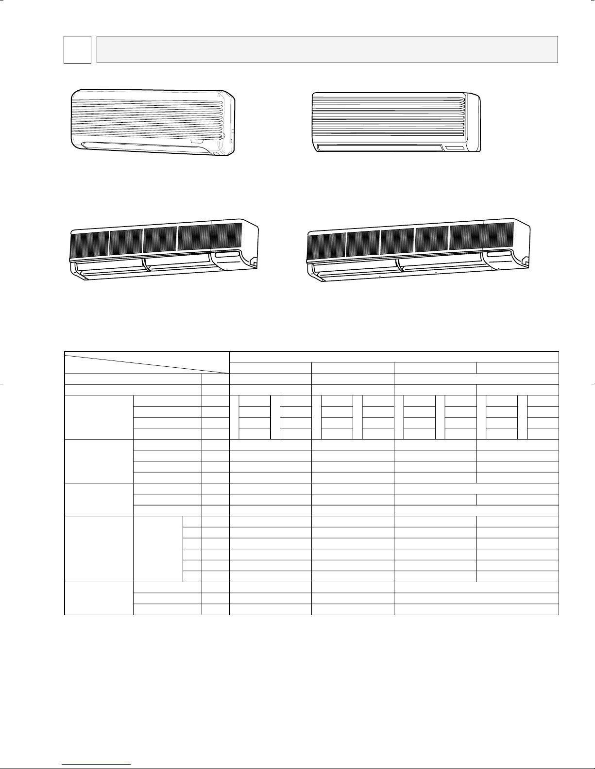
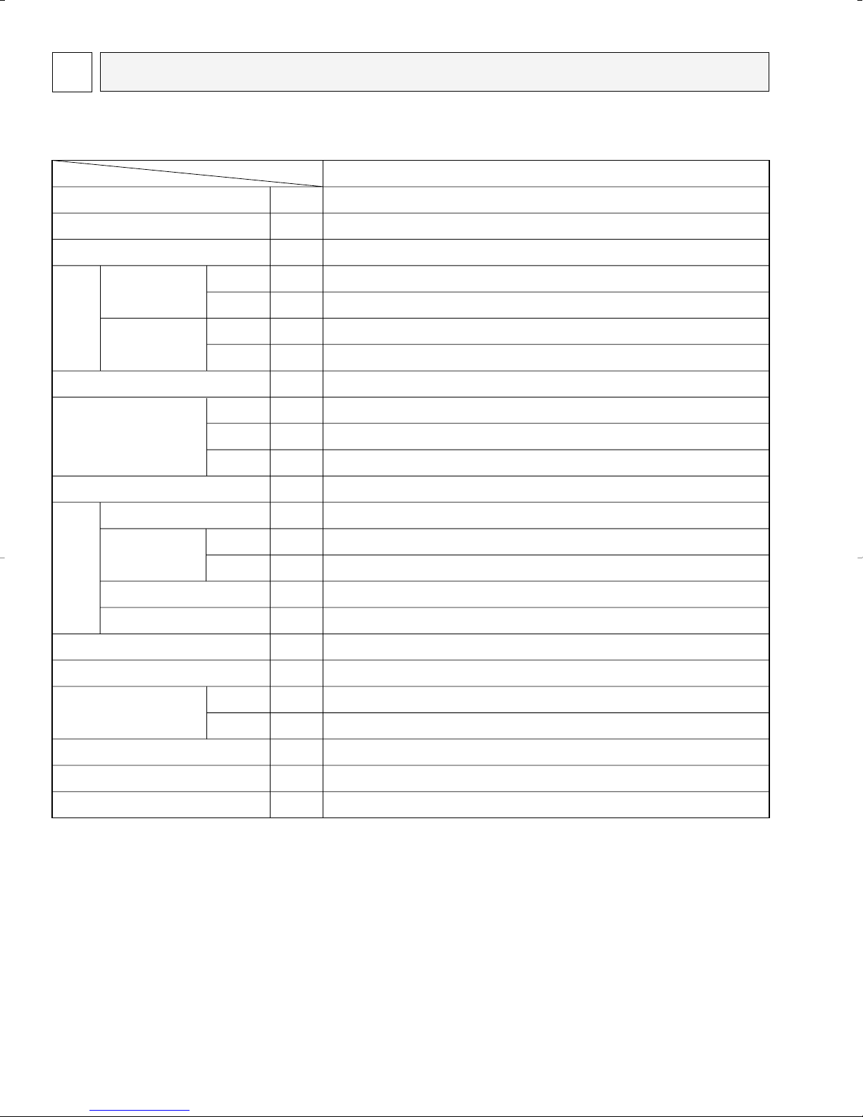
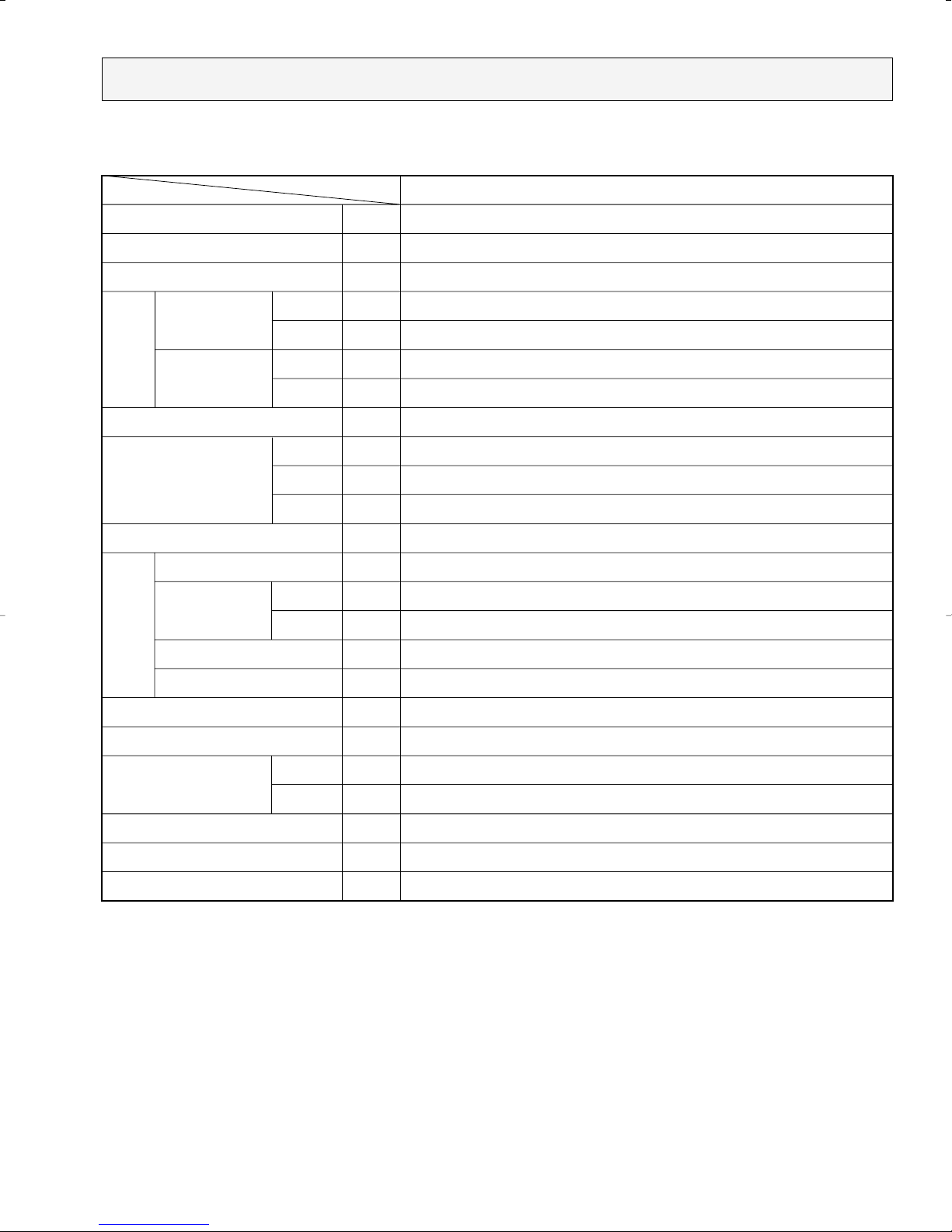
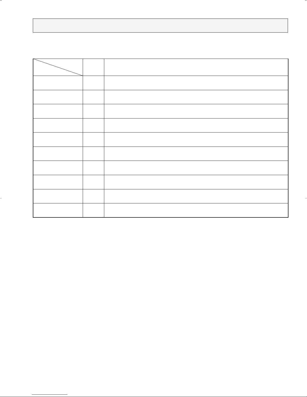
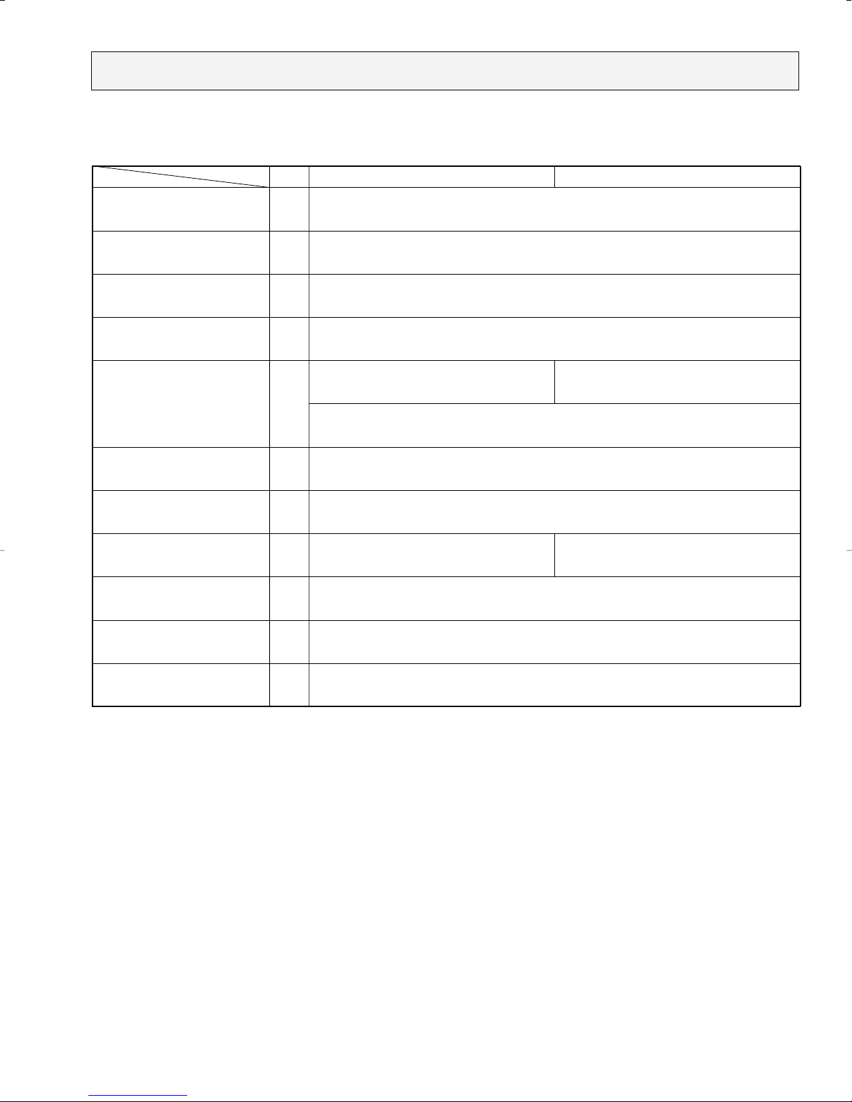
DIFFERENCES1
Lineflow fan ✕ 2
13-3/8
9-1/4
5/8"
3/8"
O.D. 13/16"
Item
Model
Fan
Fan speed
Air flow
Noise level
Out dimension
Controller board
Pipe dimension
—
—
CFM
CFM
CFM
CFM
dB
dB
dB
dB
in.
in.
in.
—
—
—
—
—
—
in.
in.
in.
1
2
3
4
5
6
High
Medium 1
Medium 2
Low
High
Medium 1
Medium 2
Low
Height
Width
Depth
SW2
Gas side
Liquid side
Drain(unit side)
08NAMU-A
Lineflow fan ✕ 1
4 speeds type
36
35
33
32
11-5/8
32-3/32
6-7/32
OFF
OFF
ON
OFF
—
—
1/2"
1/4"
O.D. 5/8"
12NGMU-A
Lineflow fan ✕ 1
4 speeds type
42
40
36
32
13-3/8
39
9-1/4
OFF
ON
ON
OFF
OFF
OFF
1/2"
1/4"
O.D. 13/16"
20NFMU-A
2 speeds type
45
—
—
39
55-1/8
OFF
ON
OFF
ON
OFF
OFF
32NFMU-A
2 speeds type
49
—
—
46
66-1/8
OFF
OFF
OFF
OFF
ON
OFF
PKFY-
210
200
180
170
190
180
170
160
D
R
Y
W
E
T
410
370
340
280
370
330
300
250
D
R
Y
W
E
T
640
—
—
490
570
—
—
440
D
R
Y
W
E
T
990
—
—
780
890
—
—
700
D
R
Y
W
E
T
PKFY-08NAMU-A
Indoor Unit
PKFY-20NFMU-A
Indoor Unit
Differences among the models of PKFY series.
PKFY-12NGMU-A
Indoor Unit
PKFY-32NFMU-A
Indoor Unit
OC292-3
2
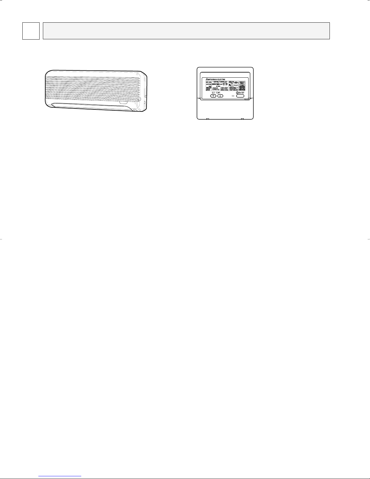
FEATURES
PKFY-08NAMU-A
Indoor Unit
Microprocessor
Remote controller
Model Cooling capacity / Heating capacity
PKFY-08NAMU-A 8,000/9,000 Btu/h
2-1. New Compact Design
• Compact 11-5/8 inch (29.5cm) high body fits snugly in even limited spaces.
• Light weight 19lbs (8.5kg) unit easy to transport and install.
2-2. Auto-flap shutter Enhances good Looks
With a simple flick of the OFF switch the air outlet can be closed off with a shutter. The shutter also functions as a flap
during operation to adjust the air flow angle, with “Auto Angle” securing a comfortable air flow.
2-3. Front power supply box for easier wiring even after installation
The front power supply box allows electrical wiring work to be done after the indoor unit has been installed. For easier
installation, all the screws required for securing the indoor unit to the wall are accessible from the front of the unit.
2-4. 4-way piping provides more flexibility in selecting installation sites
All piping including drainage can be connected from the rear, right, base, and left of the unit, providing much greater
flexibility out piping and selecting installation site.
OC292-4

PKFY-12NGMU-A
Indoor Unit
Microprocessor
Remote controller
Model Cooling capacity / Heating capacity
PKFY-12NGMU-A 12,000 / 12,500 Btu/h
2-1. New Compact Design
Units have now been downsized to require minimal wall space.
A20% reduction in width 38-31/32 inch (990mm) compared to previous models means that installation is possible in very narrow spaces.
2-2. Auto-flap shutter Enhances Good Looks
With a simple flick of the OFF switch the air outlet can be closed off with a with a shutter. The shutter also functions as a flap
during operation to adjust the air flow angle, with “Auto Angle” securing a comfortable air flow.
2-3. The Intake Grille Filter Can be Completely Removed Allowing Easy Cleaning
(Can be washed in water)
• Front grille
opens out
2-4. Quiet Operation
•Airflow passage configuration that assures quiet operation
1 The unit incorporates a randompitch cycling fan.
By changing fan intervals, quiet operation is achieved
without reduction in airflow. Optimal design of the
airflow passage gives a shortened fan diameter
and allows a highly compact installation.
2 Thanks to a highly practical casing configuration,
airflow generated by the fan is distributed uniformly.
3 Due to careful positioning of the vertical vane axis,
air is blown evenly from the outlet. This prevents mixing
with secondary air and also suppresses condensation.
2-5. 4-way Piping Provides more Flexibility in Selecting Installation Sites
OC292-5
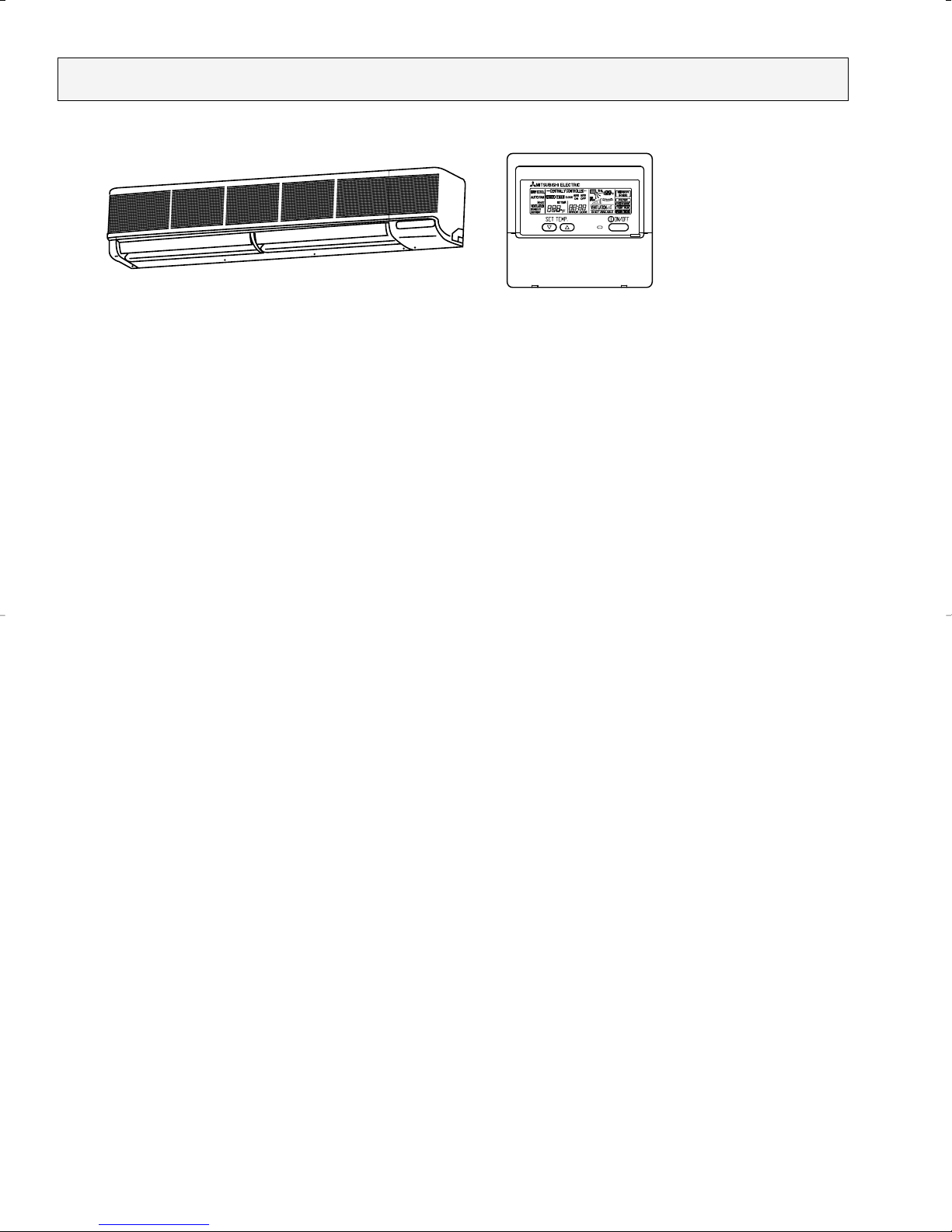
PKFY-20NFMU-A
PKFY-32NFMU-A
Indoor Unit
Microprocessor
Remote controller
Models Cooling capacity / Heating capacity
PKFY-20NFMU-A 20,000 / 22,500 Btu/h
PKFY-32NFMU-A 32,000 / 35,500 Btu/h
2-1. COMPACT DESIGN
The PKFY series models have been downsized and now require such minimal wall space that they can even be
installed above windows. For the PKFY series models, 14-9/16 inch (37 cm) of wall space between the ceiling and the
window allows “above window” installation.
2-2. A FURTHER REFINEMENT OF COMFORT WITH NISE SUPPRESSION
Remarkably tow-noise operation has been achieved through the development of a “near -silent” fan and the design
which minimises air flow resistance.
2-3. AUTO FLAP SHUTTER
With a simple flick of the OFF switch the air outlet can be closed off with a shutter. The shutter also functions as a flap
during operation to adjust the air flow angle, with “Auto Angle” securing a comfortable air flow.
2-4. INSTALLATION : FAST AND ENDLESSLY ADAPTABLE
(1) Multi-directional piping
Multi directional drain and refrigerant piping radically improves flexibility in selecting installation layouts.
PKFY- • NFMU-A models boast refrigerant piping in 4 directions and drain piping 2 directions.
(2) Back plate installation guide
The back plate installation guide gives clear instructions on installation positions. The enlarged back plate secures the
unit firmly to the wall, while the support piece which lifts the unit makes left side piping work much easier.
(3) Easily removable filter
The presence of thumbscrews on the filters means that the filters can be quickly and smoothly removed.
OC292-6
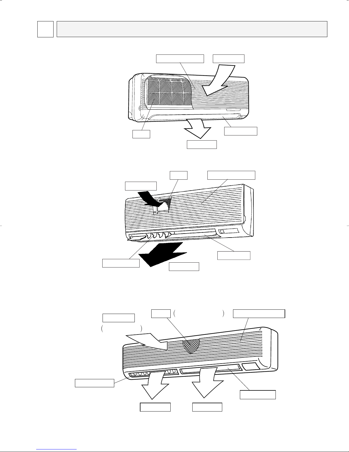
3
Air intake
Room air is
suctioned in here.
Removes dust and dirt
from the intake air.
Filter Air intake grilles
Air outletAir outlet
Auto vane
Air flow can be changed to
horizontally by moving the
Guide vane to the left or right.
Guide vane
PART NAMES AND FUNCTIONS
● Indoor Unit
[PKFY-08NAMU-A]
[PKFY-12NGMU-A]
Filter
Air intake
Air intake grille Air intake
Auto vane
Air outlet
Filter
Air intake grille
[PKFY-20NFMU-A]
[PKFY-32NFMU-A]
Guide vane
Air outlet
OC292-7
Auto vane

Press this button to switch the cooler,
electronic dry (dehumidify), automatic
and heater modes.
OPERATION SWITCH button
This sets the room temperature. The
temperature setting can be performed
in 2_F units
Setting range
Cooler 67_F to 87_F
Heater 63_F to 83_F
TEMP . ADJUSTMENT button
This switches between continuous
operation and the timer operation.
TIMER button
This switches between the operation
and stop modes each time it is pressed.
The lamp on this button lights during
operation.
ON/OFF button
Only press this button to perform an
inspection check or test operation.
Do not use it for normal operation.
CHECK-TEST RUN button
This switch the horizontal fan motion
ON and OFF.
(Not available for this model.)
LOUVER button
This adjusts the vertical angle of the
ventilation.
AIR DIRECTION button
This resets the filter service indication
display
FILTER button
This sets the current time, start time
and stop time.
TIME SETTING button
This sets the ventilation fan speed.
AIR SPEED button
● Remote controller
● Once the operation of the unit is set, subsequent operations can only be performed by pressing the ON/OFF button
repeatedly.
● Operation buttons
OC292-8
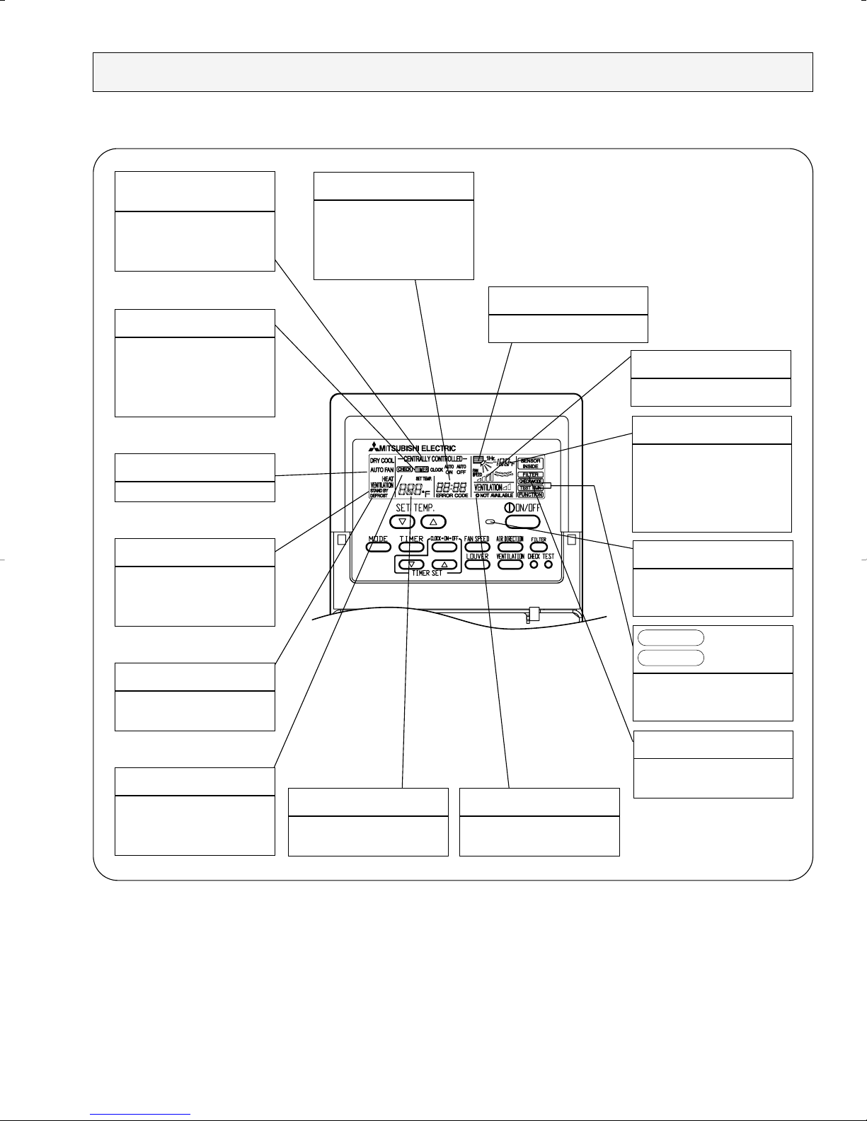
● Display
CENTRALLY
CONTROLLED display
This indicates when the unit is controlled by optional features such as
central control type remote
controller.
TIMER display
This indicates when the continuous
operation and time operation modes
are set.
It also display the time for the timer
operation at the same time as when
it is set.
OPERATION MODE display
This indicates the operation mode.
STANDBY display
The [STANDBY] symbol is only displayed from the time the heating
operation starts unit the heated air
begins to blow.
DEFROST display
This indicates when the defrost
operation is performed.
CLOCK display
The current time , start time and stop
time can be displayed in ten second
intervals by pressing the time switch
button. The start time or stop time is
always displayed during the timer
operation.
In this display example on the bottom left, a condition where all display lamps light is shown for explanation purposes although this differs
from actual operation.
AIR DIRECTION display
This displays the air direction.
AIR SPEED display
The selected fan speed is displayed.
ROOM TEMPERATURE display
The temperature of the return air
is displayed during operation. The
display range is 46_F to 102_F. The
display flashes 46_F when the actual
temperature is less than 46_F and
flashes 102_F when the actual
temperature is greater than 102_F.
Operation lamp
This lamp lights during operation,
goes off when the unit stops and
flashes when a malfunction occurs.
This display lights in the check
mode or when a test operation is
performed.
CHECK MODE
TEST RUN
display
CHECK display
This indicates when a malfunction
has occurred in the unit which should
be checked.
Caution
● Only the Power display lights when the unit is stopped and power supplied to the unit.
● When the central control remote control unit, which is sold separately, is used the ON-OFF button, operation switch button
and TEMP. adjustment button do not operate.
● “NOT AVAILABLE” is displayed when the Air speed button is pressed. This indicates that this room unit is not equipped with
the fan direction adjustment function and the louver function.
● When power is turned ON for the first time, it is normal that “H0” is displayed on the room temperature indication (For max.
2minutes). Please wait until this “H0” indication disappear then start the operation.
SET TEMPERATURE display
This displays the selected set
temperature.
FILTER display
This lamp lights when the filter need
to be cleaned.
POWER display
This lamp lights when electricity is
supplied to the unit.
OC292-9
4
Power Supply
Starting Current
Fan ✕ No.
Air flow w 2
External static pressure
Fan motor output
Item
Power
Cooling capacity
Heating capacity
Exterior <munsell symbol>
Out dimensions
Heat exchanger
Fan
Insulator
Air filter
Pipe dimensions
Unit drain pipe size
Noise level w 2
Product weight
Unit
[,V,Hz
Btu/h
Btu/h
kW
kW
A
A
—
in.
in.
in.
—
—
CFM
CFM
Pa
kW
—
—
in.
in.
in.
dB
lbs
Cooling
Heating
Cooling
Heating
Height
Width
Depth
DRY
WET
Gas side
Liquid side
PKFY-08NAMU-A
8,000
9,000
0.03
0.03
0.15
0.15
Plastic munsell : <2.60Y 8.66/0.69>
11-5/8
32-3/32
6-7/32
Cross fin
Lineflow fan ✕ 1
170-180-200-210
160-170-180-190
0
0.008
Polyethylene sheet
PP honey comb
1/2"
1/4"
PVC pipe with O.D. 5/8"
32-33-35-36
19
Electric
characteristic
Single phase, 208/230V, 60Hz
SPECIFICATIONS
4-1. Specifications
PKFY-08NAMU-A
Note 1. Rating conditions
Cooling :Indoor D.B. 80˚F W.B. 67˚F
Outdoor D.B. 95˚F W.B. 75˚F
Heating : Indoor D.B. 70˚F
ww
2. Air flow and the noise level are indicated as Low - Medium2 - Medium1 - High.
Outdoor D.B. 47˚F W.B. 43˚F
• Connected outdoor unit is PURY-80TMU or PURY-100TMU.
OC292-10
Input
Current
Fan ✕ No.
Air flow w 2
External static pressure
Fan motor output
Item
Power
Cooling capacity
Heating capacity
Exterior <munsell symbol>
Out dimensions
Heat exchanger
Fan
Insulator
Air filter
Pipe dimensions
Unit drain pipe size
Noise level w 2
Product weight
Unit
[,V,Hz
Btu/h
Btu/h
kW
kW
A
A
—
in.
in.
in.
—
—
CFM
CFM
Pa
kW
—
—
in.
in.
in.
dB
lbs
Cooling
Heating
Cooling
Heating
Height
Width
Depth
DRY
WET
Gas side
Liquid side
PKFY-12NGMU-A
Single phase, 208/230V, 60Hz
12,000
12,500
0.07
0.07
0.34
0.34
Plastic , white : <0.70Y 8.59/0.97>
13-3/8
39
9-1/4
Cross fin (Aluminum plate fin and copper tube)
Lineflow fan ✕ 1
280-340-370-410
250-300-330-370
0
0.03
Polyethylene sheet
PP honey comb
1/2"
1/4"
PVC pipe with O.D. 13/16"
32-36-40-42
35
Electric
characteristic
PKFY-12NGMU-A
Note 1. Rating conditions
W 2. Air flow and the noise level are indicated as Low - Medium2 - Medium1 - High.
Cooling : Indoor : D.B. 80_F W.B. 67_F
Heating : Indoor : D.B. 70_F
outdoor : D.B. 95_F W.B. 75_F
outdoor : D.B. 47_F W.B. 43_F
• Connected outdoor unit is PURY-80TMU or PURY-100TMU.
OC292-11

PKFY-20NFMU-A
Input
Current
Type ✕ No.
Air flow
Low - High
External static pressure
Fan motor output
Item
Power source
Cooling capacity
Heating capacity
Exterior <munsell symbol>
Dimensions
Heat exchanger
Fan
Insulator
Air filter
Pipe dimensions
Unit drain pipe dimension
Noise level Low - High
Product weight
Unit
[,V,Hz
Btu/h
Btu/h
kW
kW
A
A
—
in.
in.
in.
—
—
CFM
CFM
Pa
kW
—
—
in.
in.
in.
dB
lbs
Cooling
Heating
Cooling
Heating
Height
Width
Depth
DRY
WET
Gas side
Liquid side
PKFY-20NFMU-A
20,000
22,500
0.09
0.09
0.44
0.44
55-1/8
490 - 640
440 - 570
0.045
39 - 45
53
PKFY-32NFMU-A
32,000
35,500
0.12
0.12
0.58
0.58
66-1/8
780 - 990
700 - 890
0.070
46 - 49
62
Electric
characteristic
Single phase, 208V-220V, 60Hz
Plastic , white : <3.4Y 7.7/0.8>
13-3/8
9-1/4
Cross fin(Aluminum plate fin and copper tube)
Lineflow fan ✕ 2
0
Polyethylene sheet
PP Honeycomb fabric
5/8"
3/8"
PVC pipe with O.D. 13/16"
PKFY-30NFMU-A
Note 1. Rating conditions
Cooling : Indoor : D.B. 80_F W.B. 67_F
Heating : Indoor : D.B. 70_F
outdoor : D.B. 95_F W.B. 75_F
outdoor : D.B. 47_F W.B. 43_F
• Connected outdoor unit is PURY-80TMU or PURY-100TMU.
OC292-12
4-2. Electrical parts specifications
Parts name
Model
Symbol
TH21
TH22
TH23
FUSE
MF
C
MV
LEV
TB2
TB5
Resistance 30˚F/15.8k", 50˚F/9.6k", 70˚F/6.0k", 80˚F/4.8k", 90˚F/3.9k", 100˚F/3.2k"
Resistance 30˚F/15.8k", 50˚F/9.6k", 70˚F/6.0k", 80˚F/4.8k", 90˚F/3.9k", 100˚F/3.2k"
Resistance 30˚F/15.8k", 50˚F/9.6k", 70˚F/6.0k", 80˚F/4.8k", 90˚F/3.9k", 100˚F/3.2k"
250V 6A
4-Pole Output 8W / PS4N8
1.2µF ✕ 440V
MSFBC20A03 DC12V
(L1, L2,GR) 250V 20A
(M1, M2) 250V 10A
Liquid pipe thermistor
Gas pipe thermistor
Fan motor capacitor
Linear expansion valve
PKFY-08NAMU-A
Room temperature
thermistor
Fuse
(Indoor power board)
Fan motor
(with thermal fuse)
Vane motor
(with limit switch)
Power supply terminal
block
Transmission terminal
block
DC12V Stepping motor drive
Port [3.2 (0~2000pulse) EDM-402ME
PKFY-08NAMU-A
OC292-13

PKFY-12NGMU-A
Room temperature thermistor
Liquid pipe temperature thermistor
Gas pipe temperature thermistor
Fuse
(Indoor controller board)
Fan motor
(with inner-thermostat)
Fan motor capacitor
Vane motor
Linear expansion valve
Power supply terminal block
Transmission terminal block
MA remote controller terminal block
Symbol
TH21
TH22
TH23
FUSE
MF
C
MV
LEV
TB2
TB5
TB15
Resistance 30°F/15.8kΩ, 50°F/9.6kΩ, 70°F/6.0kΩ, 80°F/4.8kΩ, 90°F/3.9kΩ, 100°F/3.2kΩ
Resistance 30°F/15.8kΩ, 50°F/9.6kΩ, 70°F/6.0kΩ, 80°F/4.8kΩ, 90°F/3.9kΩ, 100°F/3.2kΩ
Resistance 30°F/15.8kΩ, 50°F/9.6kΩ, 70°F/6.0kΩ, 80°F/4.8kΩ, 90°F/3.9kΩ, 100°F/3.2kΩ
250V 6A
PM4N30-KA 208V/230V 60Hz
4 pole Output 30W
OPEN 257±9°F
2.0µF 440V
MP 35 EA DC12V
DC12V Stepping motor drive
Port dimension [3.2 (0 ~ 2000pulse)
(L1, L2, GR) 330V 30A
(M1, M2, S) 250V 20A
(1,2) 250V 10A
Model
Parts name
Inner-thermostat
PKFY-12NGMU-A
OC292-14
Room temperature thermistor
Liquid pipe temperature thermistor
Gas pipe temperature thermistor
Fuse
(Indoor controller board)
Fan motor
(with inner-thermostat)
Fan motor capacitor
Vane motor
Linear expansion valve
Power supply terminal block
Transmission terminal block
MA remote controller
terminal block
Symbol
TH21
TH22
TH23
FUSE
MF
C
MV
LEV
TB2
TB5
TB15
PKFY-20NFMU-A
Resistance 30°F/15.8kΩ, 50°F/9.6kΩ, 70°F/6.0kΩ, 80°F/4.8kΩ, 90°F/3.9kΩ, 100°F/3.2kΩ
Resistance 30°F/15.8kΩ, 50°F/9.6kΩ, 70°F/6.0kΩ, 80°F/4.8kΩ, 90°F/3.9kΩ, 100°F/3.2kΩ
Resistance 30°F/15.8kΩ, 50°F/9.6kΩ, 70°F/6.0kΩ, 80°F/4.8kΩ, 90°F/3.9kΩ, 100°F/3.2kΩ
250V 6A
OPEN 266±9°F
2.5= 440V
MP 35 EA DC12V
(L1, L2, GR) 330V 30A
(M1, M2, S) 250V 20A
(1,2) 250V 10A
Model
Parts name
PKFY-32NFMU-A
Inner-thermostat
DC12V Stepping motor drive
Port dimension [5.2 (0 ~ 2,000pulse)
DC12V Stepping motor drive
Port dimension [3.2 (0 ~ 2,000pulse)
D10B4P70MS
208-230V 60Hz
4pole Output 70w
D094P45MS
208-230V 60Hz
4pole Output 45w
PKFY-20NFMU-A
PKFY-30NFMU-A
OC292-15
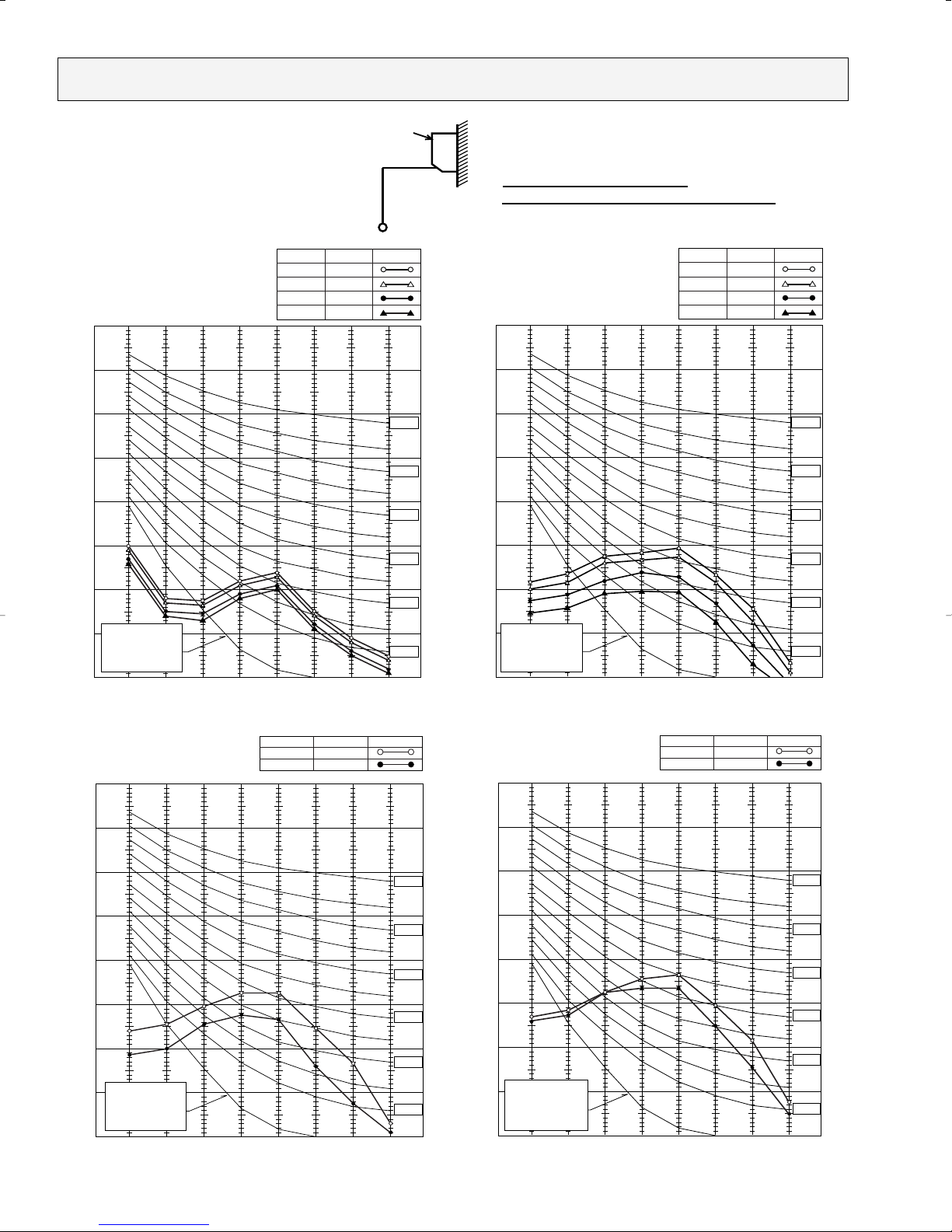
90
80
70
60
50
40
30
20
10
63 125 250 500 1000 2000 4000 8000
NC-60
NC-50
NC-40
NC-30
NC-20
NC-70
OCTAVE BAND SOUND PRESSURE LEVEL, dB re 0.0002 MICRO BAR
BAND CENTER FREQUENCIES, Hz
APPROXIMATE
THRESHOLD OF
HEARING FOR
CONTINUOUS
NOISE
PKFY-08NAMU-A
Hi
Med1
Med2
Lo
NOTCH
36
35
33
32
SPL(dB)
LINE
4-3. Noise criterion curves
Ambient temperature 80˚F
Test conditions are based on JIS Z8731
Wall
Unit
3.3ft
3.3ft
90
80
70
60
50
40
30
20
10
63 125 250 500 1000 2000 4000 8000
NC-60
NC-50
NC-40
NC-30
NC-20
NC-70
OCTAVE BAND SOUND PRESSURE LEVEL, dB re 0.0002 MICRO BAR
BAND CENTER FREQUENCIES, Hz
APPROXIMATE
THRESHOLD OF
HEARING FOR
CONTINUOUS
NOISE
PKFY-12NGMU-A
Hi
Med1
Med2
Lo
NOTCH
42
40
36
32
SPL(dB)
LINE
90
80
70
60
50
40
30
20
10
63 125 250 500 1000 2000 4000 8000
NC-60
NC-50
NC-40
NC-30
NC-20
NC-70
OCTAVE BAND SOUND PRESSURE LEVEL, dB re 0.0002 MICRO BAR
BAND CENTER FREQUENCIES, Hz
APPROXIMATE
THRESHOLD OF
HEARING FOR
CONTINUOUS
NOISE
Hi
NOTCH
Lo
49
SPL(dB)46LINE
PKFY-32NFMU-A
90
80
70
60
50
40
30
20
10
63 125 250 500 1000 2000 4000 8000
APPROXIMATE
THRESHOLD OF
HEARING FOR
CONTINUOUS
NOISE
NC-60
NC-50
NC-40
NC-30
NC-20
NC-70
BAND CENTER FREQUENCIES, Hz
OCTAVE BAND SOUND PRESSURE LEVEL, dB re 0.0002 MICRO BAR
Hi
NOTCH
Lo
45
SPL(dB)39LINE
PKFY-20NFMU-A
OC292-16
5
1-11/ 32(34)
1-11/16(42.5)
1-5/8(40.5)
Unit:inch (mm)
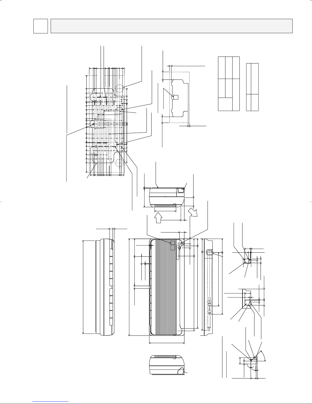
Installation space
Details of installation plate
9-3/4(247.5)
3/32(2.5)
2-3/8(60)
5-29/32(150)
20-25/32(520)
17-23/32(450)
0
3-27/32(97.5)
7-3/32(180)
0
6-1/4(159)
0
1-3/32(27.5)
4-29/32(125)
0
2-3/32(53)
0
1-3/4(45)
26-31/32(660)
Liquid pipe
Gas pipe
(Drain pipe total 29-29/32(760))
4-11/32(110)
4-9/16(116)
11-23/32(298)
9-1/4(235)
8-1/16(205)
6-7/8(175)
0
6-11/16(170)
2-9/16(65)
1-9/16(40)
0
5-1/32(128)
4-7/8(124)
3-17/32(90)
0
6-1/4(159)
6-5/8(168)
4-7/16(113)
3-7/16(87)
5-5/16(135)
4-11/32(110)
1-3/8(35)013/32(10)
0
12-29/32 (328)
4-1/32(102.5)
0
19/32(15)
0
4-13/16(122.5)
5-1/4(133)
2-27/32(72.5)
3-11/32(85)
1-7/8(47.5)
2-3/8(60)
7/8(22.5)
0
16-1/32(407.5)
12-29/32(328)
11-5/8(295)
10-1/4(260)
8-27/32(225)
7-15/32(190)
6-3/32(155)
4-23/32(120)
3-11/32(85)
0
1-3/16(30)
16-1/32(407.5)
11-23/32(298)
10-1/4(260)
8-27/32(225)
7-15/32(190)
6-3/32(155)
4-23/32(120)
3-11/32(85)
0
1-3/16(30)
13/32(10)
13/32(10)
1-31/32(50)
1-23/32(44)
0
6-7/8(175)
9-1/4(235)
6-11/16(170)
8-1/16(205)
3/16(5)
❊1
2-3/8 (60)
5-3/4 (146)
1-15/32(37.4)
2-25/32(70.3)
Air outlet
Air outlet
Air intake
Air intake
Air intake
7-3/32(180)
Air outlet
Air intake
24-13/16(630)
1/2(13)
1/2(13) 1(25.5)
27-3/8(695)
11-5/8(295)
27/32(21.5)
32-3/32(815)
3-15/16(100) or more
5-1/8(130) or more
W1 5-1/8(130) or more
25/32(20) or more
30-13/16(783)
6-7/32(158)
[2-9/16~[2-3/4
([65~[70)
Through hole
3.Sleeves are available on the market.
[2-9/16
([65)
Sleeve
Wiring entrance holes
Terminal block
Detailed figure dwg (ABC)
(Knock out hole)
R5/16(R8)
R19/32(R15)
R19/32(R15)
R19/32(R15)
R5/16(R8)
R15/32(R12)
R5/16(R8)
Knock out hole of
right piping
Knock out hole of
remocon wiring
(Direction)
Knock of hole
Knock out hole for
remocon wiring
3/16x1-3/8(4.5x35) 4 holes
installaion plate
Knock out holt for
under piping
13/32(10)
1-31/32(50)
5/8(16)
3/32(2.5)
1-25/32 (45)
3-19/32 (91.5)
Installat plate palance point hole
Supporting piece
3/16x1-9/16 (4.5x40) 4 holes
3/16x1-15/32 (4.5x37) 4 holes
12-[1/8([2.8)holes
4-[11/32([9)holes
8-[5/32([4.3) holes
87-[3/16([5.1)holes
Piping hole[2-9/16([65)
2-1/8(54)
Knock out hole for
left piping
45
-
31/32(24.4)
3
-
5
-
1-25/32(45)13/32(10)
13/32(10)
1-11/32(34)
5/8 (16)
3/32(2.5)
1-31/32 (50)
5/32(4)
Air intake
Air outlet
(Direction)
Installation plate
2-1/8(54) of more
leftpiping
left-rear piping
Notes 1.Use M10 or W3/8 screw for installation plate.
2.Extension piping side.
[5/8([16) I.D
1/2F
1/4F
Drain pipe
Liquid pipe
Gas pipe
Refrigerart
piping
C
C
B
A
B
A
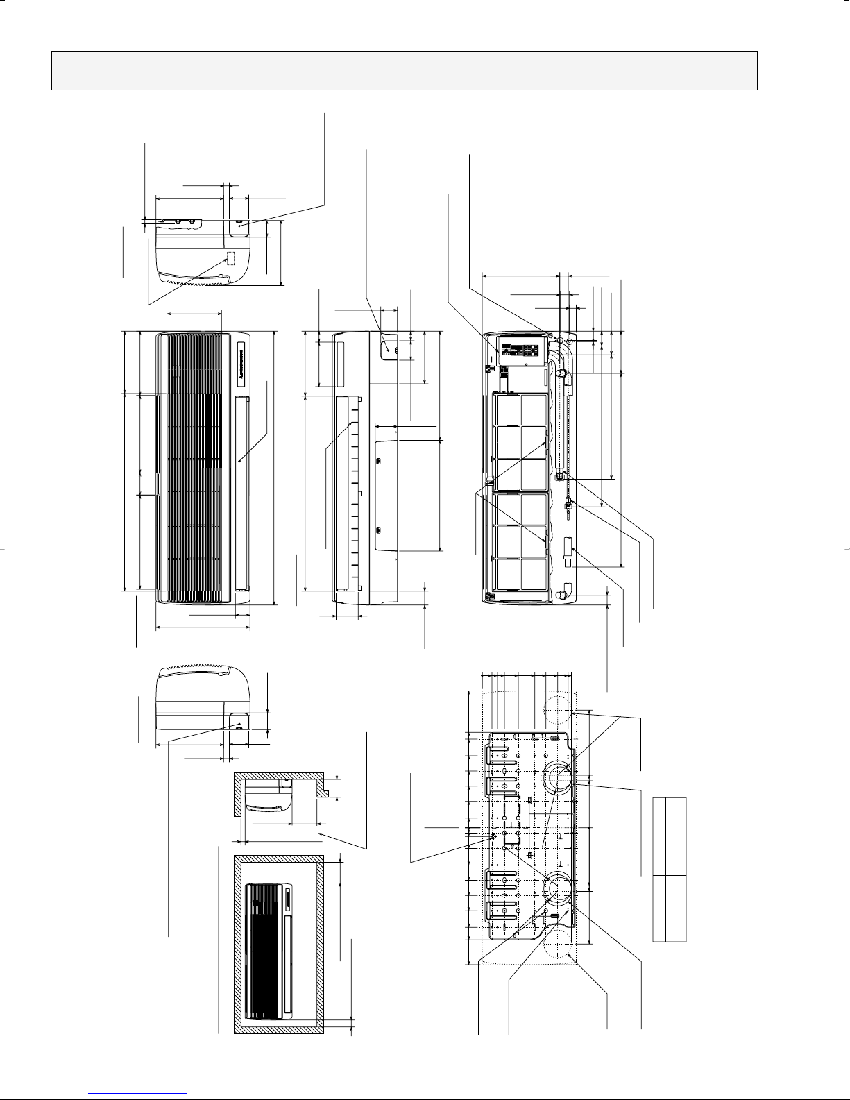
OUTLINES AND DIMENSIONS
PKFY-08NAMU-A
Unit : inch(mm)
OC292-17
Drain hose
Wiring entrance holes
3/16(5)
1(25)
1-11/32(34)
1-5/16(33)
Air intake
Air intake
Service space required around indoor unit
Details of installation plate
Front view (top open the grille)
Lower side
Right side
Left side
Front view
22-7/8(581)
17-11/16(449)
Installation plate
balance point hole
Knock out hole for right piping
Refrigerant pipe.Drain pipe.
Wiring hole
Gas pipe 1/2F
Liquid pipe 1/4F
49-[3/16([5)holes
for tapping screw
Knock out hole for
right-rear piping
Right-rear
piping hole
(Necessary clearance for
Unit installation)
Address board
Filter grip
13/16(21)
13/16(21)
R2-1/16(R52.5)
R2-1/16(R52.5)
R2-1/16(R52.5)
R2-1/16(R52.5)
Unit center
Knock out hole for under piping
Refrigerant piping.Drain pipe.
Wiring hole
Service panel
(Power supply access)
Right side
w1 Sleeves are available on the market.
w2 This size shows the lower end of through hole.
[2-15/16~[3-5/32
([75~[80)
[2-15/16([75)
Through holeSleeve W1
14-[9/16([14)holes
for bolts
Left-rear
piping hole
Knock out hole for
left-rear piping
(Flexible hose total length 31-1/2(800))
(Right side piping installation)
(Left side piping
installation)
12—Louvers (manual)
Auto vane
Air intake
Knock out hole for left piping
Refrigerant pipe.Drain pipe.Wiring hole.
1-3/8(35)
Less than 5-1/8(130)
1-31/32(50) or more
5-29/32(150) or more
7-3/32(180) or more
1-13/16(30) or more
27-9/16(700) 6-1/32(153)
3-3/8(86)
2-1/8(54)
1-7/32(31) 11-1/32(280)
3-1/8(80)
2-3/8(60)
2-3/4(70)
9-21/32(245)
1-31/32(50)
15-9/16(395)15-3/4(400)
7-15/32(190)
2-3/8(60)
2-3/4(70) 1-3/8(35)
3-1/8(79)
6-5/16(160) 1-9/16(40)
27-3/4(705) Air outlet 9-1/4(235)
Less than 19/32(15)
7-25/32(198)
2-3/4(70)
9-21/32(245)
2-3/8(60)
9-1/4(235)
2-3/32(53)
13-3/8(340)
28-5/32(715) Air intake 8-27/32(225)
13-3/8(340)
3-5/32(80)
11-1/32(280) 9-3/16(233)
39(990)
16-23/32(425)
16-17/32(420)
6-11/16(170)
7-15/32(190)
8-9/32(210)
9-1/16(230)
0
12-11/16(322)w1
0
1-3/8(35)
2-5/32(55)
3-5/32(80)
5-1/8(130)
7-15/32(190)
9-1/16(230)
10-23/32(272)
12-7/32(310)
0
1-3/8(35)
3-3/4(95)
5-29/32(150)
8-1/16(205)
10-1/4(260)
12-19/32(320)
13-19/32(345)
19-1/2(495)
25/32(20)
2-15/16(75)
5-5/16(135)
7-15/32(190)
9-21/32(245)
11-13/16(300)
14-3/16(360)
15-15/16(405)
19-1/2(495)
1-1/4(32)
0
PKFY-12NGMU-A
Unit : inch(mm)
OC292-18
15/16(24)
1-5/16(34)
1-7/16(36)
1
Wiring entrance holes
Terminal blockTerminal block
Details of installation plate
Knock out hole
for right piping
Right side
Front view
Top side
1-31/32(50) or more
9-27/32(250) or more
9-27/32(250) or more
1-3/16(30) or more
Less than 9-27/32(250)
Service space required around indoor unit
3-19/32(91)
8-27/32(225)
7-1/4(184)
1-3/16(30)
9-7/16(240)
7-3/32(180)
11-1/32(280) 12-3/8(314)
23/32(18)
23/32(18)
13/32✕3-19/32=(35-13/16) (10✕91=(910)) 11-7/32(285)
1-3/16(30)
1-3/16(30)
3/4(19)
35-7/16(900)
3-17/32(90)
24-1/32(610)
11-1/32(280)
2-3/8(60)
9-21/32(245)
17-29/32(455)
1-5/32(29)
13/32(10)
38-31/32(990)
3-1/8(80)
12-1/4(6) holes
for tapping screws
32-[15/32([12) holes
for bolts
Wall fixture
Rear piping hole
66-[1/4([6) holes
for tapping screws
Unit center
Bolt
Less than 19/32(15)
Drain hose
4-3/8(111)
Drain hose for
left-hand side piping
4-7/32(107)
7-7/32(183)
2-5/32(55)
4-23/32(120)
1-21/32(42)
2-9/32(58)
Drain hose
1-25/32(45)
1-25/32(45)
1-25/32(45)
Knock out hole for wiring
AB C
1-3/16(30)
1-3/16(30)
1-17/32(39)
B
A
2-29/32(74)
C
3-27/32(98)
1-15/32(37)
2-29/32(74)
1-15/32(37)
2-9/16(65)
5/32(4)
1-17/32(39)
1-9/16(39)
3-15/16(100)
1-1/4(32)
1-15/32(37)
3-15/16(100)
5/32(4)
21-23/32(552) Air outlet
44-3/32(1120)
13-3/8(340)
7-3/4(197)
1/2(13)
2-15/32(62.5)
9-1/4(235) 9-1/4(235)
55-1/8(1400)
9-7/16(240)
42-29/32(1090) Air intake
9-1/4(235)
21-23/32(552) Air outlet
9-1/4(235)
9-1/4(235)
Sleeve
2
31/32(25)
43-11/16(1110) Drain hose
Knock out hole
for left piping
Drainage range on
left hand side
Knock out hole for under-piping
Refrigerant pipe /Drain pipe
Drainage range on
right-hand side
[3-17/32
([90)
w1 Sleeves are available
on the market.
w1
Through hole
Left side
Lower side
Louvers(Manual)Auto vanes
Range for left rear piping hole
Under panel(Removable at
left-hand side piping)
[3-17/32~[3-15/16
([90~[100)
1
2
5/8F
3/8FLiquid pipe
Gas pipe
Air
outlet
Air
intake
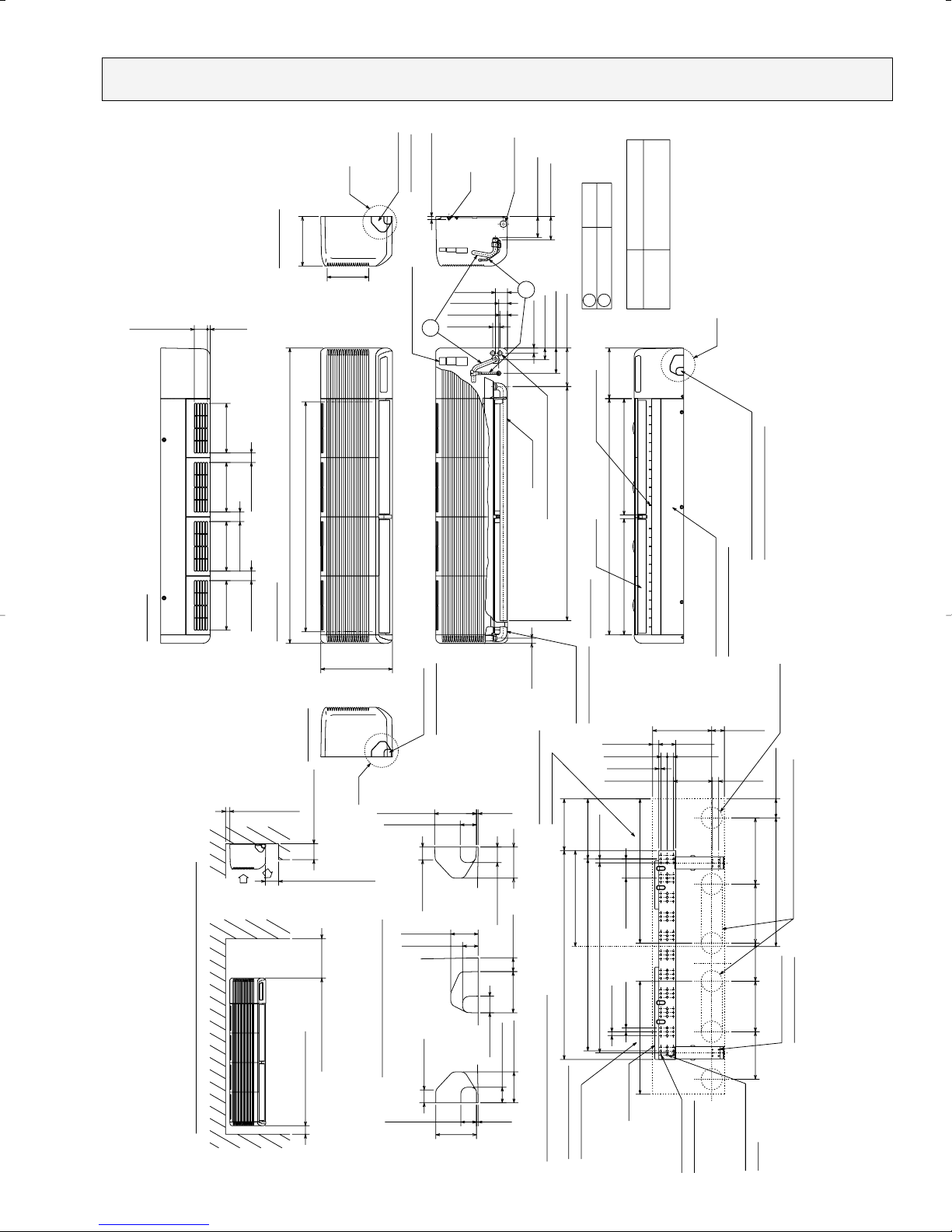
PKFY-20NFMU-A
Unit : inch(mm)
OC292-19
Front view
15/16(24)
1-5/16(34)
1-7/16(36)
Wiring entrance holes
Terminal block
1-31/32(50) or more
9-27/32(250) or more
Less than 5-29/32(150)
9-27/32(250) or more
1-3/16(30) or more
Less than 9/16(15)
1
2
Gas pipe
Liquid pipe 3/8F
5/8F
Sleeve
[3-17/32~[3-15/16
([90~[100)
Through hole
[3-17/32
([90)
w1
w1 Sleeves are available
on the market.
Unit out line
Wall fixture
Rear piping hole
11-5/8(295) 8-27/32(225)
1-3/16(30) 7-1/4(184)
9-7/16(240) 7-3/32(180) 11-1/32(280) 12-3/8(314)
23/32(18)
23/32(18)
3-5/32(80)
1/2✕3-19/32=(46-9/16) (13✕91=(1183))
3-19/32(91)
50(1270)
13/32(10)
1-3/16(30)
1-3/16(30)
3/4(19)
35-7/16(900)
23-7/16(595)
29-17/32(750)
2-3/8(60)
9-21/32(245)
11-7/32(285)
3-9/16(90)
1-5/32(29)
11-1/32(280)
84-[1/4([6) holes
for tapping screws
41-[15/32([12) holes
for bolts
12-[1/4([6) holes
for tapping screws
Unit center
Bolt
Range for left rear piping hole
Drainage range on
left hand side
Drainage range on
right-hand side
1
2
A
ACB
3-15/16(100)
5/32(4) 1-17/32(39)
2-29/32(74)
1-15/32(37)
2-9/16(65)
1-15/32(37)
1-17/32(39)
1-1/4(32)
3-27/32(98)
5/32(4)
2-29/32(74)
1-15/32(37)
1-17/32(39)
3-15/16(100)
1-3/16(30)
1-3/16(30)
Drain hose for
left-hand side piping
1-21/32(42)
2-9/32(58)
27-5/16(694) Air outlet
9-7/16(240)
1-25/32(45)
13-3/8(340)
1/2(13)
1-25/32(45)
2-15/32(62.5)
9-1/4(235)
1-25/32(45)
9-1/4(235)
Service space required around indoor unit
55-1/8(1400)
9-1/4(235)
53-15/16(1370) Air intake
9-1/4(235)
7-7/32(183)
2-5/32(55)
Under panel(Removable at
left-hand side piping)
4-23/32(120)
27-5/16(694) Air outlet
9-1/4(235)
C
Drain hose
66-1/8(1680)
4-3/8(111)
4-1/32(102)
43-11/16(1110) Drain hose
31/32(25)
7-3/4(197)
9-1/4(235)
Knock out hole
for left piping
Knock out hole for under-piping
Refrigerant pipe /Drain pipe
Right side
Left side
Top side
1-25/32(45)
Lower side
Louvers(Manual)
B
Knock out hole for wiring
Auto vanes
Knock out hole
for right piping
Air
outlet
Air
intake
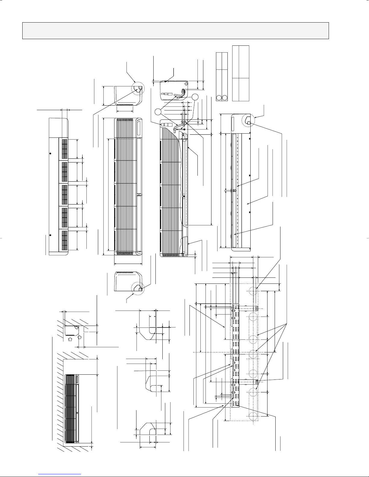
PKFY-32NFMU-A
Unit : inch(mm)
OC292-20
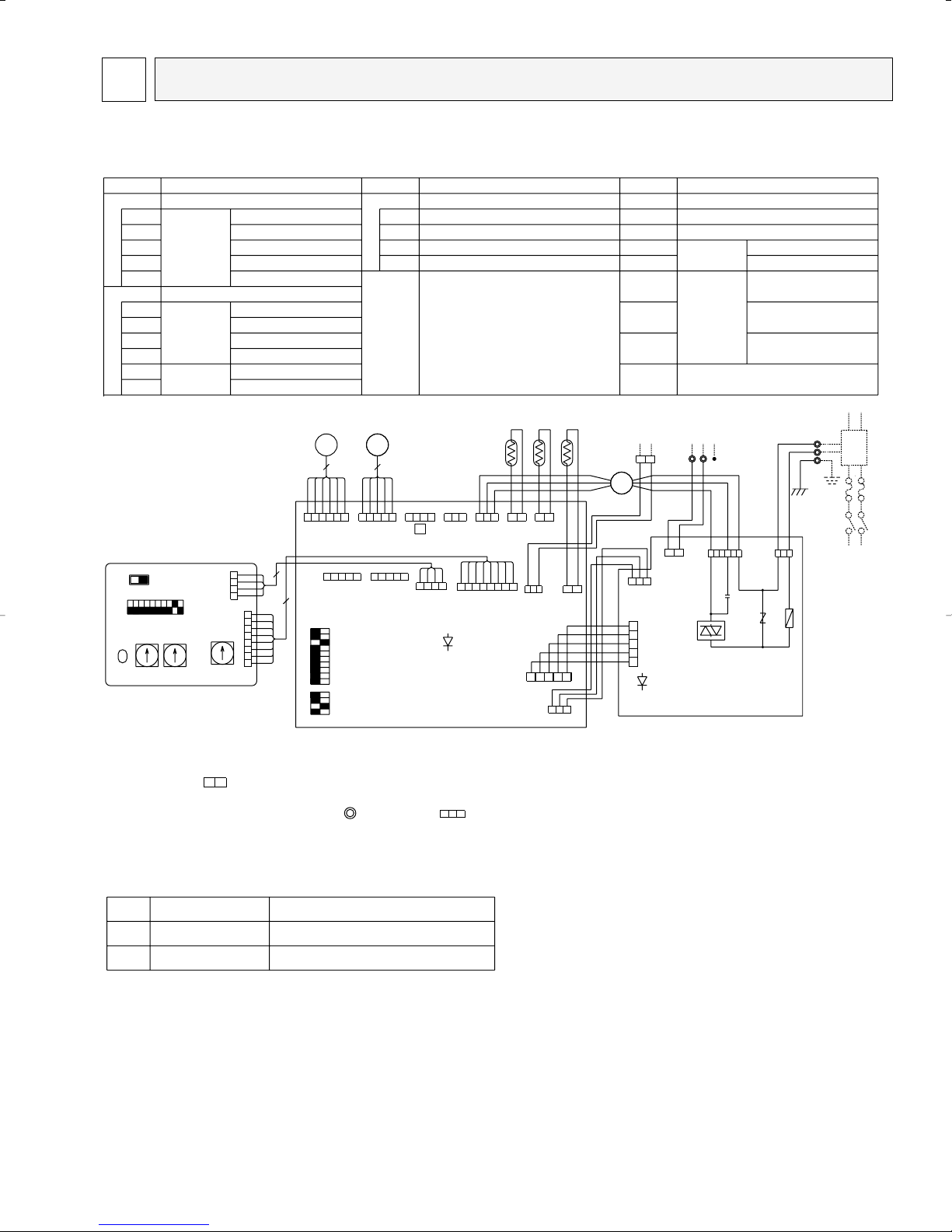
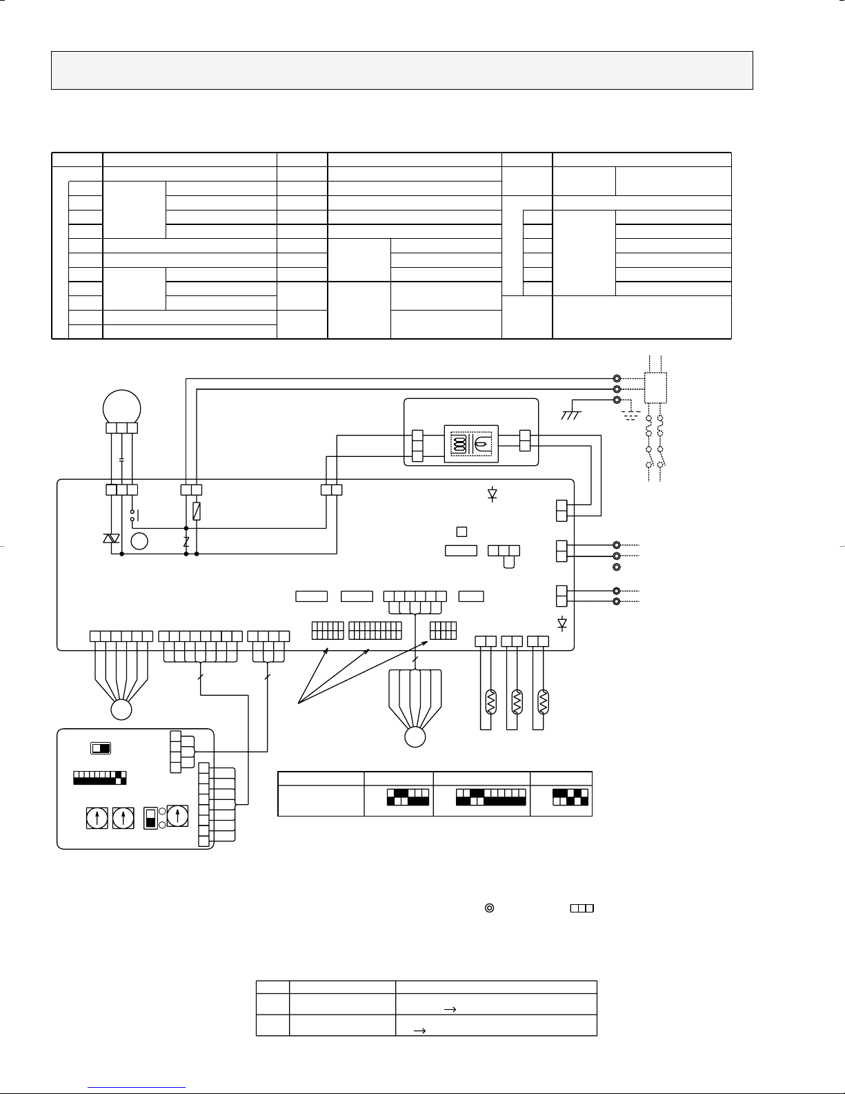
WIRING DIAGRAM6
21
LEV
56
YLW
ORN
BLU
PNK
RED
BRN
RED
BLU
ORN
YLW
5VDC SUPPLY
(WHT)
ADDRESS SETTING 2ND DIGIT
CIRCUIT BOARD (ADDRESS)A.B
SW1
SW5
SW11
SW12
SW14
VOLTAGE SELECTION
CONNECTION No.
SWITCH MODE SELECTION
ADDRESS SETTING 1ST DIGIT
[LEGEND]
NAME
TH22
TH21
THERMISTOR
CONNECTOR
M.B
SYMBOL
CN32
CN41
CN51
CN52
SWITCHSW2
SW3
LEV LINEAR EXPANSION VALVE
ROOM TEMPERATURE DETECTION
(32°F/15kΩ,77°F/5.4kΩ)
PIPE
TEMPERATURE
DETECTION
/LIQUID (32°F/15kΩ,77°F/5.4kΩ)
F.C FAN PHASE CONTROL
FUSE FUSE (6A/250V)
VARISTORZNR
SYMBOL
NAME
SYMBOL
INDOOR POWER BOARDP.B
CAPACITY CODE
MODE SELECTION
REMOTE INDICATION
CENTRALLY CONTROL
HA TERMINAL-A
REMOTE SWITCH
INDOOR CONTROLLER BOARD
TH23
MF
C CAPACITOR (FAN MOTOR)
PIPE TEMPERATURE DETECTION
/GAS (32°F/15kΩ,77°F/5.4kΩ)
TB2
TB5
FAN MOTOR
MV VANE MOTOR
NAME
TRANSMISSION
POWER SUPPLY
TERMINAL
BLOCK
GR
L1
to the connector .(Remote controller wire is non-polar.)
TB5 S(SHIELD)
TB2
L2
TO NEXT
INDOOR UNIT
PULL
BOX
FUSE
(15A)
~/N 208-230V 60Hz
BREAKER
(15A)
POWER SUPPLY
GRN/YLW
ORN
ORN
Mark
LED1
LED2
Meaning
Main power supply
Function
Power supply for
MA-Remote controller
LED on indoor board for service
Main power supply(Indoor unit:208-230V)
power on ➔ lamp is lit
Power supply for MA-Remote controller
on ➔ lamp is lit
3.In case of using M-NET,please connect to TB5.(Transmission line is non-polar.)
In case of connecting MA-Remote controller,please connect MA remote controller cable in an accessorie2.
CN35P
MICON
BOARD
(BLU)
CN53P
MICON
BOARD
(RED)
(BLU)
(RED)
POWER BOARD
POWER BOARD
CN53M
CN35M
CN43
ADDRESS
(RED)
(RED)
ADDRESS
CN82
SW5
208V
230V
3RD
DIGIT
2ND
DIGIT
1ST
DIGIT
CONNECTION
NO.
(WHT)
CENTRALLY
CONTROL
(GRN)
REMOTE
INDICATION
(RED)
ADDRESS
(RED)
ADDRESS
(BLU)
CN20
INTAKE
(RED)
(BLU)
(GRN)
(RED)
BLU
RED
BLK
RED
WHT
BLU
BLU
M-NET REMOTE CONTROLLER
TO OUTDOOR UNIT
BC CONTROLLER
CONTROLLER
TO MA-REMOTE
LIQUID
(BLK)
GAS
(GRN)
SWITCH
(WHT)
(WHT)
(WHT)
WHT
BLK
BRN
BRN
RED
YLW
ORN
ORN
YLW
5.
4.
1.
Notes:
Symbols used in wiring diagram above are, :terminal block, :connecter, ●:direct wire connection.
At servicing for outdoor unit,always follow the wiring diagram of outdoor unit.
Please set the switch SW5 according to the power supply voltage.
Set SW5 to 230V side when the power supply is 230 volts.
When the power supply is 208 volts,set SW5 to 208V side.
CN5V
(BLU)
CN41
HA
REMOTE
CN32
CN34
CN29
LEV
CN60
CN3A
CN81
CN42
CN52
CN51
12345678910
SW3
0FF
0N
1234
SW2
LED2
M.B
CN21
CN2M
M-NET
FAN
CND
C
FUSE
250V
6A
8
4
ON
OFF
12345678910
SW1
SW12 SW11
SW14
A.B
00
0
LED1
TH22
TH23
TH21
MF
M1
M2
DC24-30V
DC8.7-13V
{
P.B
ZNR
F.C
MV
{
2
532
2
2
1
654321
12345
4321
123 123 1 2 21
32145
32145
4123
612345 78
31
12
13245
123
1
2
3
4
5
6
7
8
1
2
3
4
5
4
2
3
1
321
12
146
13
PKFY-08NAMU-A
OC292-21
0
5VDC SUPPLY
REMOTE
SWITCH
ADDRESS SETTING 2ND DIGIT
13
SW3
109876
ON
OFF
12345
SW2
ON
OFF
123456
SW4
ON
OFF
12345
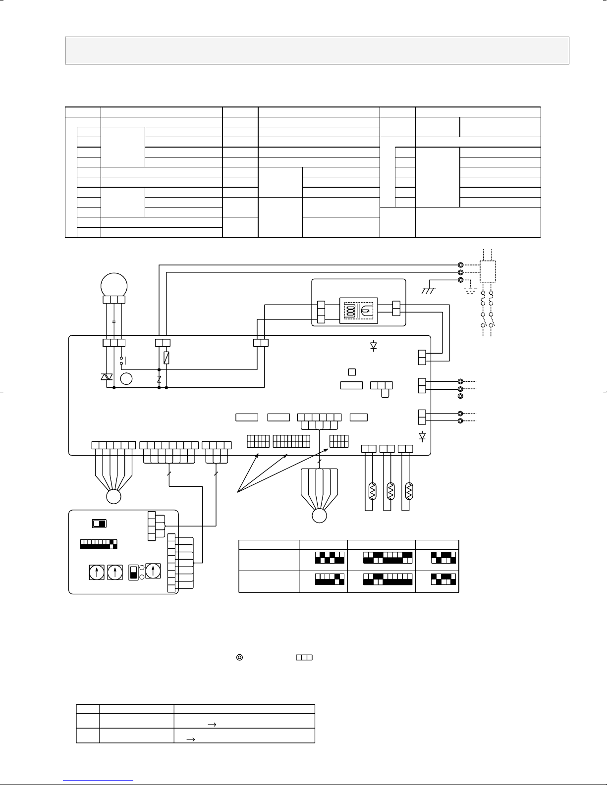
PKFY-12NGMU-A
Model
0
SW12 SW11
00
CONNECTION
NO.
1ST
DIGIT
2ND
DIGIT
3RD
DIGIT
ON
OFF
SWC
10987654321
CN82(RED)
ADDRESS
SW14
CN43(RED)
ADDRESS
SW5
230V
SW1
208V
A.B
X4
BRN
RED
ORN
YLW
PNK
BLU
MV
8
ADDRESS
CN81(RED)
CN6V(GRN)
VANE
C
BLK
WHT
RED
I.B
(WHT)
FAN
F.C
X4
CND
(RED)
ZNR
6A
250V
FUSE
LEV
TH22 TH23TH21
See fig:w1
<fig:w1>
4
ADDRESS
CN42(RED)
BLK
WHT
5
CN52(GRN)
REMOTE
INDICATION
1
SW2
0FF
0N
65432110987654321
12345
6
BRN
RED
BLU
ORN
YLW
WHT
5
1
SW3
(RED)
CNDK
CENTRALLY
CONTROL
CN51(WHT)
LEV
CN60(WHT)
4
HA
CN41(WHT)
1
CN32(WHT)
3
1
SW4
0FF
0N
CN21
LIQUID
(WHT)
INTAKE
CN20
(RED)
CN29
GAS
(BLK)
LED2
ORN
ORN
BLU
BLU
WHT
BLK
M-NET
(BLU)
CN3A
(BLU)
CN2M
(WHT)
CN2D
LED1
CN31(WHT)
DRAIN
P.B
CNSK
AC208-230V
(RED)
TRANS
(WHT)
DC13.1V
CN2S
GRN/YLW
RED
BLU
TB2
L1
L2
GR
TB5
M2
M1
TB15
2
1
TO NEXT INDOOR UNIT
PULL BOX
BREAKER
(15A)
FUSE(15A)
~/N 208-230V 60Hz
POWER SUPPLY
TO OUTDOOR UNIT
BC CONTROLLER
DC24-30V
REMOTE CONTROLLER
{
S(SHIELD)
DC8.7-13V
{
TO MA-REMOTE
CONTROLLER
SYMBOL
I.B
CN32
CN41
CN51
CN52
F.C
FUSE
SW2
SW3
SW4
X4
ZNR VARISTOR
AUX. RELAY (FAN MOTOR)
MODEL SELECTION
MODE SELECTION
CAPACITY CODESWITCH
FUSE (6A/250V)
FAN PHASE CONTROL
REMOTE INDICATION
CENTRALLY CONTROL
HA TERMINAL-A
CONNECTOR
REMOTE SWITCH
INDOOR CONTROLLER BOARD
NAME
SYMBOL
NAME
SW1
SW5
SW11
SW12
SW14
SWC
OPTION SELECTOR
CONNECTION No.
ADDRESS SETTING 1ST DIGIT
VOLTAGE SELECTION
MODE SELECTIONSWITCH
CIRCUIT BOARD (ADDRESS)
A.B
TH23
SYMBOL
NAME
Mark
LED1
LED2
Power supply for
MA-Remote controller
Main power supply
Meaning
LED on indoor board for service
Function
Main power supply(Indoor unit:208-230V)
power on lamp is lit
Power supply for MA-Remote controller
on lamp is lit
321
THERMISTOR
(32°F/15kΩ,77°F/5.4kΩ)
PIPE TEMPERATURE DETECTION/GAS
INDOOR POWER BOARD
P.B
MA-REMOTE CONTROLLER
TB15
121221
4
3
2
1
8
7
6
5
4
3
2
1
2
1
3
2
1
13
2
1
3
1
1
2
123456
513
MF
123412345678561234
MV
MF
C
VANE MOTOR
TERMINAL
BLOCK
TB5
TB2
FAN MOTOR(WITH INNER THERMOSTAT)
POWER SUPPLY
TRANSMISSION
LEV
LINEAR EXPANSION VALVE
CAPACITOR (FAN MOTOR)
(32°F/15kΩ,77°F/5.4kΩ)
PIPE TEMPERATURE DETECTION/LIQUID
(32°F/15kΩ,77°F/5.4kΩ)
ROOM TEMPERATURE DETECTION
TH22
TH21
THERMISTOR
1. At servicing for outdoor unit,always follow the wiring diagram of outdoor unit.
2. In case of using MA-Remote controller, please connect to TB15.
(Remote controller wire is non-polar.)
3. In case of using M-NET, please connect to TB5.
(Transmisson line is non-polar.)
4. Symbol[S] of TB5 is the shield wire connection.
5. Symbols used in wiring diagram above are, :terminal block, :connecter.
6.
The setting of the SW2/SW3/SW4 dip switches differs in the capacity for the detail, refer to the fig:w1.
7. Please set the switch SW5 according to the power supply voltage.
Set SW5 to 230V side when the power supply is 230 volts.
When the power supply is 208 volts, set SW5 to 208V side.
Notes:
[LEGEND]
2
1
PKFY-12NGMU-A
OC292-22
0
5VDC SUPPLY
REMOTE
SWITCH
ADDRESS SETTING 2ND DIGIT
13
SW3SW2 SW4
4
54321
OFF
ON
ON
OFF
123 5
654321
OFF
ON
ON
123456
54321
OFF
ON
678910
54321
OFF
ON
678910
OFF
Models
PKFY-20NFMU-A
PKFY-32NFMU-A
0
SW12 SW11
00
CONNECTION
NO.
1ST
DIGIT
2ND
DIGIT
3RD
DIGIT
ON
OFF
SWC
10987654321
CN82(RED)
ADDRESS
SW14
CN43(RED)
ADDRESS
SW5
230V
SW1
208V
A.B
X4
BRN
RED
ORN
YLW
PNK
BLU
MV
8
ADDRESS
CN81(RED)
CN6V(GRN)
VANE
C
BLK
WHT
RED
I.B
(WHT)
FAN
F.C
X4
CND
(RED)
ZNR
6A
250V
FUSE
LEV
TH22 TH23TH21
See fig:w1
<fig:w1>
4
ADDRESS
CN42(RED)
BLK
WHT
5
CN52(GRN)
REMOTE
INDICATION
1
SW2
0FF
0N
65432110987654321
12345
6
BRN
RED
BLU
ORN
YLW
WHT
5
1
SW3
(RED)
CNDK
CENTRALLY
CONTROL
CN51(WHT)
LEV
CN60(WHT)
4
HA
CN41(WHT)
1
CN32(WHT)
3
1
SW4
0FF
0N
CN21
LIQUID
(WHT)
INTAKE
CN20
(RED)
CN29
GAS
(BLK)
LED2
ORN
ORN
BLU
BLU
WHT
BLK
M-NET
(BLU)
CN3A
(BLU)
CN2M
(WHT)
CN2D
LED1
CN31(WHT)
DRAIN
P.B
CNSK
AC208-230V
(RED)
TRANS
(WHT)
DC13.1V
CN2S
GRN/YLW
RED
BLU
TB2
L1
L2
GR
TB5
M2
M1
TB15
2
1
TO NEXT INDOOR UNIT
PULL BOX
BREAKER
(15A)
FUSE(15A)
~/N 208-230V 60Hz
POWER SUPPLY
TO OUTDOOR UNIT
BC CONTROLLER
DC24-30V
REMOTE CONTROLLER
{
S(SHIELD)
DC8.7-13V
{
TO MA-REMOTE
CONTROLLER
SYMBOL
I.B
CN32
CN41
CN51
CN52
F.C
FUSE
SW2
SW3
SW4
X4
ZNR VARISTOR
AUX. RELAY (FAN MOTOR)
MODEL SELECTION
MODE SELECTION
CAPACITY CODESWITCH
FUSE (6A/250V)
FAN PHASE CONTROL
REMOTE INDICATION
CENTRALLY CONTROL
HA TERMINAL-A
CONNECTOR
REMOTE SWITCH
INDOOR CONTROLLER BOARD
NAME
SYMBOL
NAME
SW1
SW5
SW11
SW12
SW14
SWC
OPTION SELECTOR
CONNECTION No.
ADDRESS SETTING 1ST DIGIT
VOLTAGE SELECTION
MODE SELECTIONSWITCH
CIRCUIT BOARD (ADDRESS)
A.B
TH23
SYMBOL
NAME
Mark
LED1
LED2
Power supply for
MA-Remote controller
Main power supply
Meaning
LED on indoor board for service
Function
Main power supply(Indoor unit:208-230V)
power on lamp is lit
Power supply for MA-Remote controller
on lamp is lit
321
THERMISTOR
(32°F/15kΩ,77°F/5.4kΩ)
PIPE TEMPERATURE DETECTION/GAS
INDOOR POWER BOARD
P.B
MA-REMOTE CONTROLLER
TB15
121221
4
3
2
1
8
7
6
5
4
3
2
1
2
1
3
2
1
13
2
1
3
1
1
2
123456
513
MF
123412345678561234
MV
MF
C
VANE MOTOR
TERMINAL
BLOCK
TB5
TB2
FAN MOTOR(WITH INNER THERMOSTAT)
POWER SUPPLY
TRANSMISSION
LEV
LINEAR EXPANSION VALVE
CAPACITOR (FAN MOTOR)
(32°F/15kΩ,77°F/5.4kΩ)
PIPE TEMPERATURE DETECTION/LIQUID
(32°F/15kΩ,77°F/5.4kΩ)
ROOM TEMPERATURE DETECTION
TH22
TH21
THERMISTOR
1. At servicing for outdoor unit,always follow the wiring diagram of outdoor unit.
2. In case of using MA-Remote controller, please connect to TB15.
(Remote controller wire is non-polar.)
3. In case of using M-NET, please connect to TB5.
(Transmisson line is non-polar.)
4. Symbol[S] of TB5 is the shield wire connection.
5. Symbols used in wiring diagram above are, :terminal block, :connecter.
6. The setting of the SW2 / SW3 / SW4 dip switches differs in the capacity for the detail,refer to the fig:w1.
7. Please set the switch SW5 according to the power supply voltage.
Set SW5 to 230V side when the power supply is 230 volts.
When the power supply is 208 volts,set SW5 to 208V side.
Notes:
[LEGEND]
2
1
PKFY-20NFMU-A PKFY-32NFMU-A
OC292-23
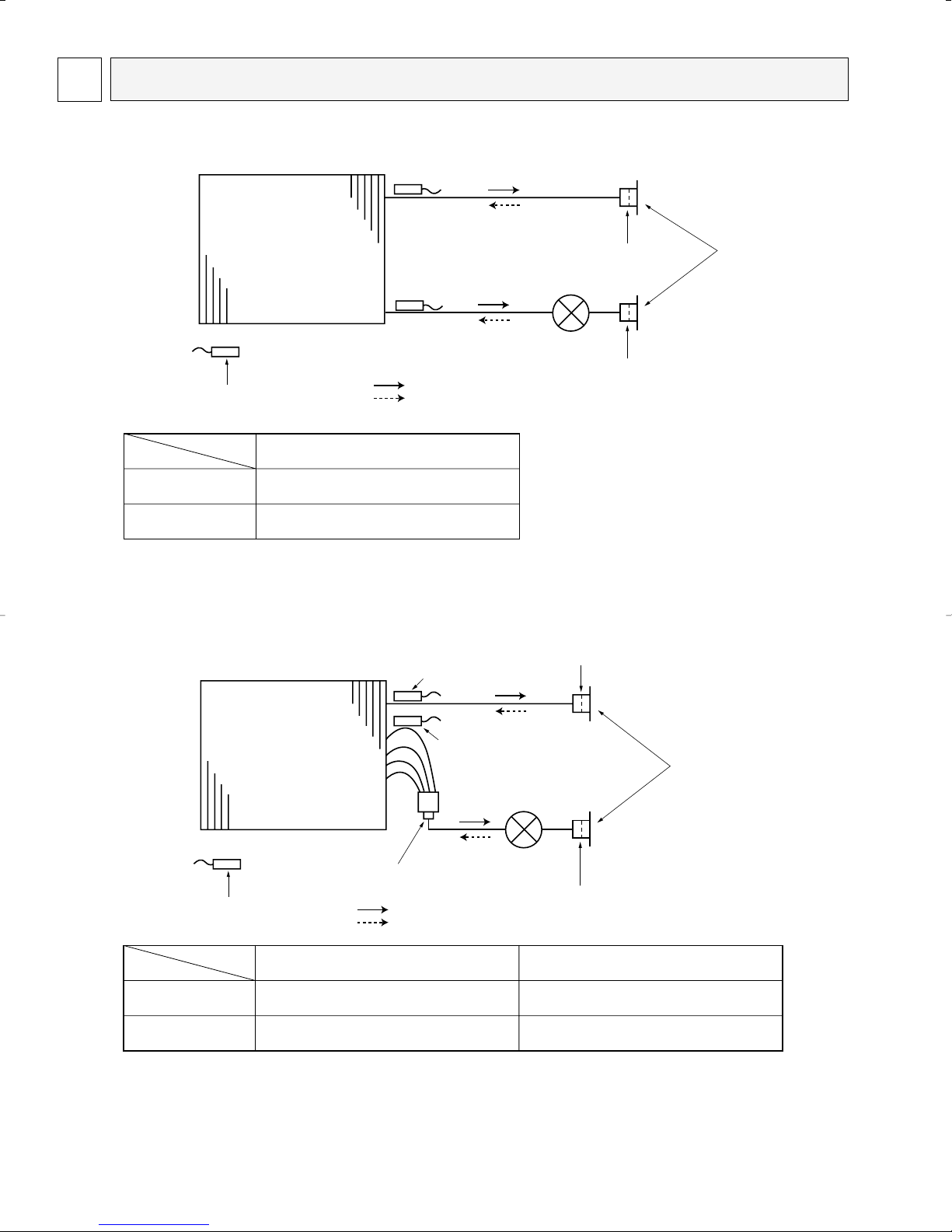
7 REFRIGERANT SYSTEM DIAGRAM
Strainer
(#100mesh)
Strainer
(#50mesh)
Heat exchanger
Room temperature
thermistor TH21
Gas pipe temperature thermistor
TH23
Liquid pipe temperature thermistor
TH22
Gas pipe
Liquid pipe
Flare
Linear expansion
valve
Refrigerant flow in cooling
Refrigerant flow in heating
Strainer (#50mesh)
Strainer (#100mesh)
Strainer (#100mesh)
Heat exchanger
Room temparature
thermistor TH21
Gas pipe thermistor
thermistor TH23
Liquid pipe thermistor TH22
Linear expansion valve
Gas pipe
Liquid pipe
Flare connection
Refrigerant flow in cooling
Refrigerant flow in heating
Gas pipe
Liquid pipe
PKFY-20NFMU-A
PKFY-32NFMU-A
5/8''
3/8''
Item
Service Ref.
PKFY-12NGMU-A
1/2''
1/4''
Gas pipe
Liquid pipe
Item
Service Ref.
PKFY-08NAMU-A
1/2''
1/4''
PKFY-08NAMU-A
PKFY-12NGMU-A
PKFY-20NFMU-A
PKFY-32NFMU-A
OC292-24
MICROPROCESSOR CONTROL8
Control modes
Control details
1-1. Thermoregulating function (Function to prevent restarting for 3 minutes)
• Room temperature ] desired temperature + 2°F
···Thermo ON
• Room temperature [ desired temperature
···Thermo OFF
1-2. Anti-freezing control
Detected condition : When the liquid pipe temp. (TH22) is 36°F or less in 16
minutes from compressors start up, anti-freezing control
starts and the thermo OFF.
Released condition : The timer which prevents reactivating is set for 3 minutes,
and anti- freezing control is cancelled when any one of the
following conditions is satisfied.
1 Liquid pipe temp. (TH22) turn 50°F or above.
2 The condition of the thermo OFF has become complete
by thermoregulating, etc.
3 The operation modes became mode other than COOL.
4 The operation stopped.
By the remote controller setting (switch of 4 speeds or 2 speeds)
2. Fan
1. Thermoregulating
function
Remarks
Type
Fan speed notch
[Low], [Med2], [Med1], [High]
[Low], [High]
4 speeds type
2 speeds type
To be continued on the next page.
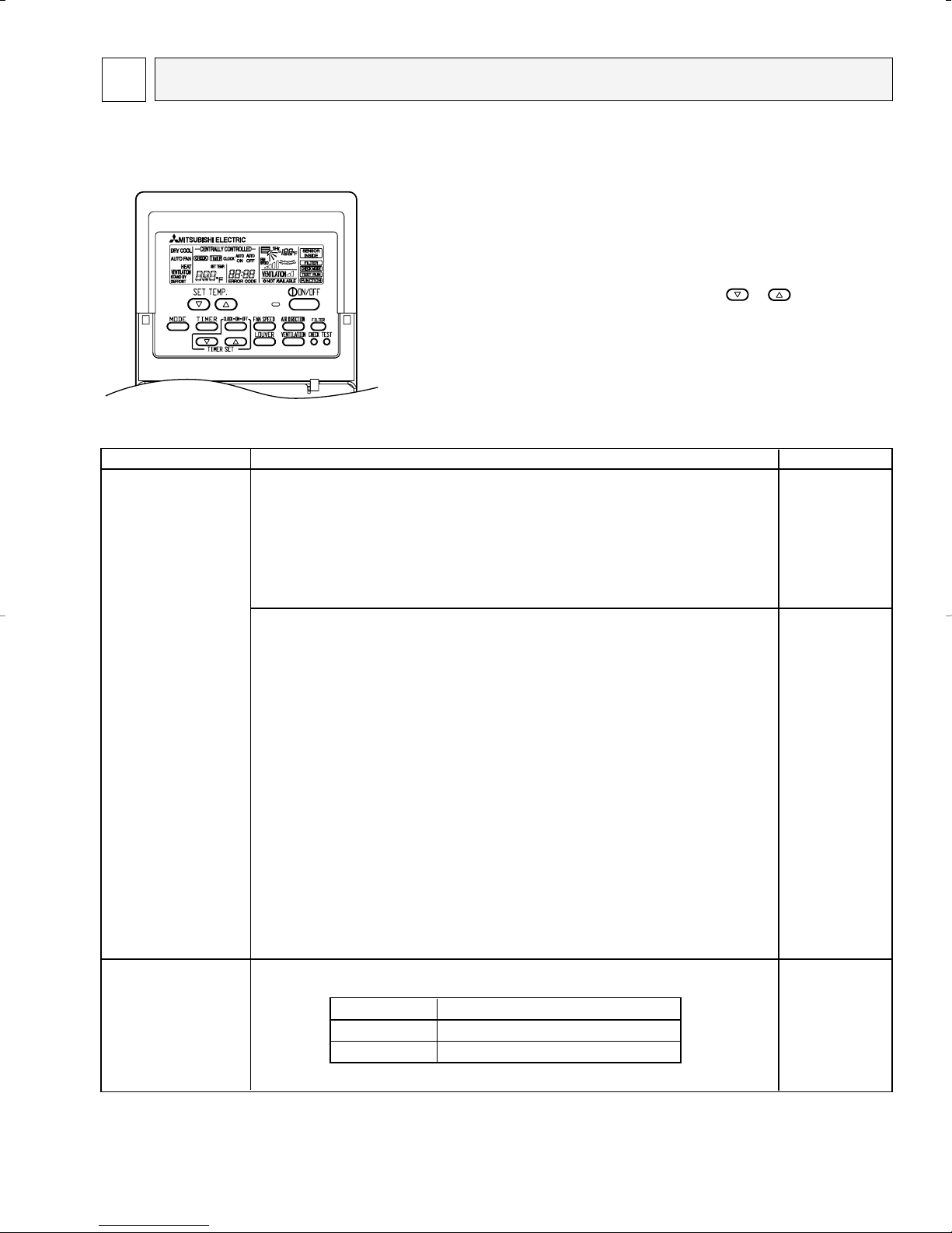
INDOOR UNIT CONTROL
8-1. COOL operation
<How to operate>
1 Press POWER ON/OFF button.
2 Press the operation MODE button to display COOL.
3 Press the SET TEMP. button to set the desired temperature.
NOTE: The set temperature changes 2°F when the or button is
pressed one time Cooling 67 to 87°F.
OC292-25
→→
3
2
1
→
3
2
1
→
Control modes
Control details
3-1. Drain pump control
•Always drain pump ON during the COOL and DRY mode operation.
(Regardless of the thermo ON/ OFF)
•When the operation mode has changed from the COOL or DRY to the others
(including Stop), OFF the control after the drain pump ON for 3 minutes.
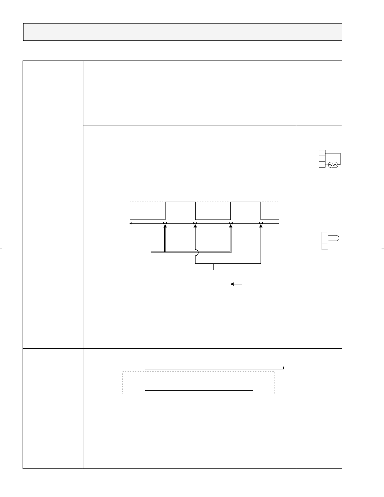
Drain sensor function
• Energize drain sensor at a fixed voltage for a fixed duration. After energizing,
compare the drain sensor’s temperature to the one before energizing, and judge
whether the sensor is in the air or in the water.
Basic control system
• While drain pump is turned on, repeat the following control system and judge
whether the sensor is in the air or in the water.
•Drain sensor temperature rise (∆t)
•Temperature of drain sensor before current is applied (T0)
•Temperature of drain sensor after current is applied (T
1)
[ ∆t = T1 – T0 ]
(1)Initial setting : Start at COOL mode and horizontal vane.
(2)Vane position : Horizontal →Downward A →Downward B →Downward C→Swing
PKFY-08NAMU-A is not equipped with the swing function.
: Horizontal →Downward A →Downward B →Downward C
(3) In case of PKFY-08NAMU-A and PKFY-12NGMU-A :
Restriction of the downward vane setting
When setting the downward vane A, B or C in [Med1], [Med2] or [Low] of the fan
speed notch, the vane changes to horizontal position after 1 hour have passed.
In case of PKFY-20NFMU-A and PKFY-32NFMU-A :
Restriction of the downward vane setting
When setting the downward vane A, B or C in [Low] of the fan speed notch,
the vane changes to horizontal position after 1 hour have passed.
4. Vane
(up/ down vane change)
3. Drain pump
Except for
PKFY-08NAMU-A.
Remarks
W
1
"SET FOR 1 HOUR"
appears on the
wired remote
controller.
Timing of
energizing
drain sensor
ON
OFF
Stand by for
a minute
30 sec.
Detect the
temperature
before
energizing
(T0)
Detect the
temperature
after
energizing
(T1)
Judge whether
the sensor is in
the air or in the
water.
30 sec.Stand by for
a minute
·······Repeat
From the preceding page.
W1 Drain sensor
Indoor control
p.c. board
CN31
W2 If the unit is
without the drain
sensor, install
the jumper
connector.
Indoor control
p.c. board
CN31
When installing
the jumper
connector,
determine to
detect
compulsorily in
the air.
OC292-26
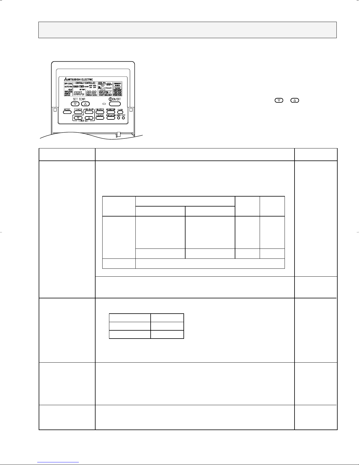
8-2. DRY operation
<How to operate>
1 Press POWER ON/OFF button.
2 Press the operation MODE button to display DRY.
3 Press the SET TEMP. button to set the desired temperature.
NOTE: The set temperature changes 2°F when the or button is
pressed one time. Dry 67 to 87°F.
Control modes
1. Thermoregulating
function
2. Fan
Control details
1-1. Thermoregulating function (Function to prevent restarting for 3 minutes)
Setting the Dry thermo by the thermoregulating signal and the
room temperature (TH1).
Dry thermo ON Room temperature ] desired temperature + 2°F
Dry thermo OFF Room temperature [ desired temperature
Room
temperature
Over 64°F
Less than 64°F
3 min. passed since starting operation
Thermoregulating signal
ON
OFF
Room temperature (T1)
82°F > T1 ] 79°F
79°F > T1 ] 75°F
75°F > T1
Unconditional
Dry thermo OFF
Dry thermo
time (min)
T1 ] 82°F
Dry thermo
ON
93
7
5
33
3
OFF
time (min)
1-2. Frozen prevention control
No control function
Indoor fan operation controlled depends on the compressor conditions.
Dry thermo
ON
OFF
Fan speed notch
[Low]
Stop
Remarks
3
3
10
Note: Remote controller setting is not acceptable.
3. Drain pump
Same control as COOL operation
Except for
PKFY-08NAMU-A.
4. Vane
Same control as COOL operation
(up/ down vane change)
OC292-27
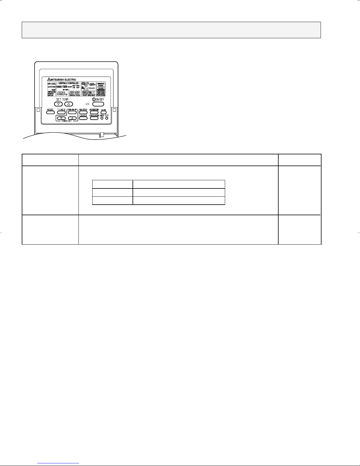
Control modes
Control details
Set by remote controller.
Remarks
1. Fan
2. Vane
(up/ down vane change)
Same as the control performed during the COOL operation, but with no restriction
on the vane's downward blow setting.
Type
Fan speed notches
[Low], [Med2], [Med1], [High]
[Low], [High]
4 speeds type
2 speeds type
8-3. FAN operation
<How to operate>
1 Press POWER ON/OFF button.
2 Press the operation MODE button to display FAN.
OC292-28
 Loading...