

Mitsubishi PKA-RP_GAL, PKH-P_GALH Installation Manual

Air-Conditioners
PKA-RP·GAL
PKH-P·GALH
INSTALLATION MANUAL
For safe and correct use, read this manual and the outdoor unit installation manual thoroughly before installing
the air-conditioner unit.
INSTALLATIONSHANDBUCH
Aus Sicherheitsgründen und zur richtigen Anwendung vor Installation der Klimaanlage die vorliegende Bedienungsanleitung und das Installationshandbuch gründlich durchlesen.
MANUEL D’INSTALLATION
Avant d’installer le climatiseur, lire attentivement ce manuel, ainsi que le manuel d’installation de l’appareil
extérieur pour une utilisation sûre et correct.
INSTALLATIEHANDLEIDING
Lees deze handleiding en de installatiehandleiding van het buitenapparaat zorgvuldig door voordat u met het
installeren van de airconditioner begint.
MANUAL DE INSTALACIÓN
Para un uso seguro y correcto, lea detalladamente este manual de instalación antes de montar la unidad de
aire acondicionado.
MANUALE DI INSTALLAZIONE
Per un uso sicuro e corretto, prima di installare il condizionatore d’aria leggere attentamente il presente
manuale ed il manuale d’installazione dell’unità esterna.
E°XEIPI¢IO O¢H°IøN E°KATA™TA™H™
°И· ЫˆЫЩ‹ О·И ·ЫК·П‹ ¯Ъ‹ЫЛ, ‰И·‚¿ЫЩВ ЪФЫВОЩИО¿ ·˘Щfi ЩФ ВБ¯ВИЪ›‰ИФ, О·ıТ˜ О·И ЩФ ВБ¯ВИЪ›‰ИФ
ВБО·Щ¿ЫЩ·ЫЛ˜ ЩЛ˜ ВНˆЩВЪИО‹˜ МФУ¿‰·˜, ЪИУ ·fi ЩЛУ ВБО·Щ¿ЫЩ·ЫЛ ЩЛ˜ МФУ¿‰·˜ ОПИМ·ЩИЫЩИОФ‡.
MANUAL DE INSTALAÇÃO
Para uma utilização segura e correcta, leia atentamente este manual e o manual de instalação da unidade
exterior antes de instalar o aparelho de ar condicionado.
FOR INSTALLER
FÜR INSTALLATEURE
POUR L’INSTALLATEUR
VOOR DE INSTALLATEUR
PARA EL INSTALADOR
PER L’INSTALLATORE
°π∞ ∞À∆√¡ ¶√À ∫∞¡∂π ∆∏¡ ∂°∫∞∆∞™∆∞™∏
PARA O INSTALADOR
English
Deutsch
Français
Nederlands
Español
Italiano
∂ППЛУИО¿
Português
INSTALLATIONSMANUAL
Læs af sikkerhedshensyn denne manual samt manualen til installation af udendørsenheden grundigt, før du
installerer klimaanlægget.
INSTALLATIONSMANUAL
Läs bruksanvisningen och utomhusenhetens installationshandbok noga innan luftkonditioneringen installeras så
att den används på ett säkert och korrekt sätt.
MONTAJ ELK‹TABI
Emniyetli ve do¤ru kullanım için, klima cihazını monte etmeden önce bu kılavuzu ve dıfl ünite montaj kılavuzunu
tamamıyla okuyun.
РУКОВОДСТВО ПО УСТАНОВКЕ
Для обеспечения безопасной и надлежащей эксплуатации внимательно прочтите данное руководство и
руководство по установке наружного прибора перед установкой кондиционера.
TIL INSTALLATØREN
FÖR INSTALLATÖREN
MONTÖR ‹Ç‹N
ДЛЯ УСТАНОВИТЕЛЯ
Dansk
Svenska
Türkçe
Русский
Contents
1. Safety precautions ................................................................................... 2
2. Installation location .................................................................................. 3
3. Installing the indoor unit ........................................................................... 3
4. Installing the refrigerant piping ................................................................. 5
1. Safety precautions
s Before installing the unit, make sure you read all the “Safety precau-
tions”.
s Please report to your supply authority or obtain their consent before
connecting this equipment to the power supply system.
Warning:
Describes precautions that must be observed to prevent danger of injury or
death to the user.
Caution:
Describes precautions that must be observed to prevent damage to the unit.
Warning:
• Ask a dealer or an authorized technician to install the unit.
• For installation work, follow the instructions in the Installation Manual and use
tools and pipe components specifically made for use with refrigerant specified
in the outdoor unit installation manual.
• The unit must be installed according to the instructions in order to minimize
the risk of damage from earthquakes, typhoons, or strong winds. An incorrectly installed unit may fall down and cause damage or injuries.
• The unit must be securely installed on a structure that can sustain its weight.
• If the air conditioner is installed in a small room, measures must be taken to
prevent the refrigerant concentration in the room from exceeding the safety
limit in the event of refrigerant leakage. Should the refrigerant leak and cause
the concentration limit to be exceeded, hazards due to lack of oxygen in the
room may result.
5. Drainage piping work ............................................................................... 6
6. Electrical work .......................................................................................... 7
7. Test run .................................................................................................. 11
8. Easy maintenance function (Option) ...................................................... 14
After installation work has been completed, explain the “Safety precautions,” use, and
maintenance of the unit to the customer according to the information in the Operation
Manual and perform the test run to ensure normal operation. Both the Installation
Manual and Operation Manual must be given to the user for keeping. These manuals
must be passed on to subsequent users.
: Indicates a part which must be grounded.
Warning:
Carefully read the labels affixed to the main unit.
• Ventilate the room if refrigerant leaks during operation. If refrigerant comes
into contact with a flame, poisonous gases will be released.
• All electric work must be performed by a qualified technician according to
local regulations and the instructions given in this manual.
• Use only specified cables for wiring.
• The terminal block cover panel of the unit must be firmly attached.
• Use only accessories authorized by Mitsubishi Electric and ask a dealer or
an authorized technician to install them.
• The user should never attempt to repair the unit or transfer it to another location.
• After installation has been completed, check for refrigerant leaks. If refrigerant leaks into the room and comes into contact with the flame of a heater or
portable cooking range, poisonous gases will be released.
1.1. Before installation (Environment)
Caution:
• Do not use the unit in an unusual environment. If the air conditioner is installed in areas exposed to steam, volatile oil (including machine oil), or sulfuric
gas, areas exposed to high salt content such as the seaside, the performance
can be significantly reduced and the internal parts can be damaged.
• Do not install the unit where combustible gases may leak, be produced, flow,
or accumulate. If combustible gas accumulates around the unit, fire or explosion may result.
• Do not keep food, plants, caged pets, artwork, or precision instruments in the
direct airflow of the indoor unit or too close to the unit as these items can be
damaged by temperature changes or dripping water.
1.2. Before installation or relocation
Caution:
• Be extremely careful when transporting the units. Two or more persons are
needed to handle the unit as it weighs 20 kg or more. Do not grasp the packaging bands. Wear protective gloves as you can injure your hands on the
fins or other parts.
• Be sure to safely dispose of the packaging materials. Packaging materials,
such as nails and other metal or wooden parts may cause stabs or other
injuries.
1.3. Before electric work
Caution:
• Be sure to install circuit breakers. If not installed, electric shock may result.
• For the power lines, use standard cables of sufficient capacity. Otherwise, a
short circuit, overheating, or fire may result.
• When installing the power lines, do not apply tension to the cables.
• When the room humidity exceeds 80% or when the drainpipe is clogged, water may drip from the indoor unit. Do not install the indoor unit where such
dripping can cause damage.
• When installing the unit in a hospital or communications office, be prepared
for noise and electronic interference. Inverters, home appliances, high-frequency medical equipment, and radio communications equipment can cause
the air conditioner to malfunction or breakdown. The air conditioner may also
affect medical equipment, disturbing medical care, and communications equipment, harming the screen display quality.
• Thermal insulation of the refrigerant pipe is necessary to prevent condensation. If the refrigerant pipe is not properly insulated, condensation will be formed.
• Place thermal insulation on the pipes to prevent condensation. If the drainpipe is installed incorrectly, water leakage and damage to the ceiling, floor,
furniture, or other possessions may result.
• Do not clean the air conditioner unit with water. Electric shock may result.
• Tighten all flare nuts to specification using a torque wrench. If tightened too
much, the flare nut can break after an extended period.
• Be sure to ground the unit. If the unit is not properly grounded, electric shock
may result.
• Use circuit breakers (ground fault interrupter, isolating switch (+B fuse), and
molded case circuit breaker) with the specified capacity. If the circuit breaker
capacity is larger than the specified capacity, breakdown or fire may result.
1.4. Before starting the test run
Caution:
• Turn on the main power switch more than 12 hours before starting operation.
Starting operation just after turning on the power switch can severely damage the internal parts.
• Before starting operation, check that all panels, guards and other protective
parts are correctly installed. Rotating, hot, or high voltage parts can cause
injuries.
2
• Do not operate the air conditioner without the air filter set in place. If the air
filter is not installed, dust may accumulate and breakdown may result.
• Do not touch any switch with wet hands. Electric shock may result.
• Do not touch the refrigerant pipes with bare hands during operation.
• After stopping operation, be sure to wait at least five minutes before turning off
the main power switch. Otherwise, water leakage or breakdown may result.
2. Installation location
420
495
405
360
300
245
190
135
7532200352595
205
260
320
345
495
150
230
210
140
170
190
425
40
0
0
35
55
80
130
190
230
272
310
340
322
*
A
B
C
D
E
F
G
H
I
J
K
L
M
N
B
Y
Z
V
100
A
C
D
E
B
E
D
C
B
A
F
H
D
W
G H
Fig. 2-1
3. Installing the indoor unit
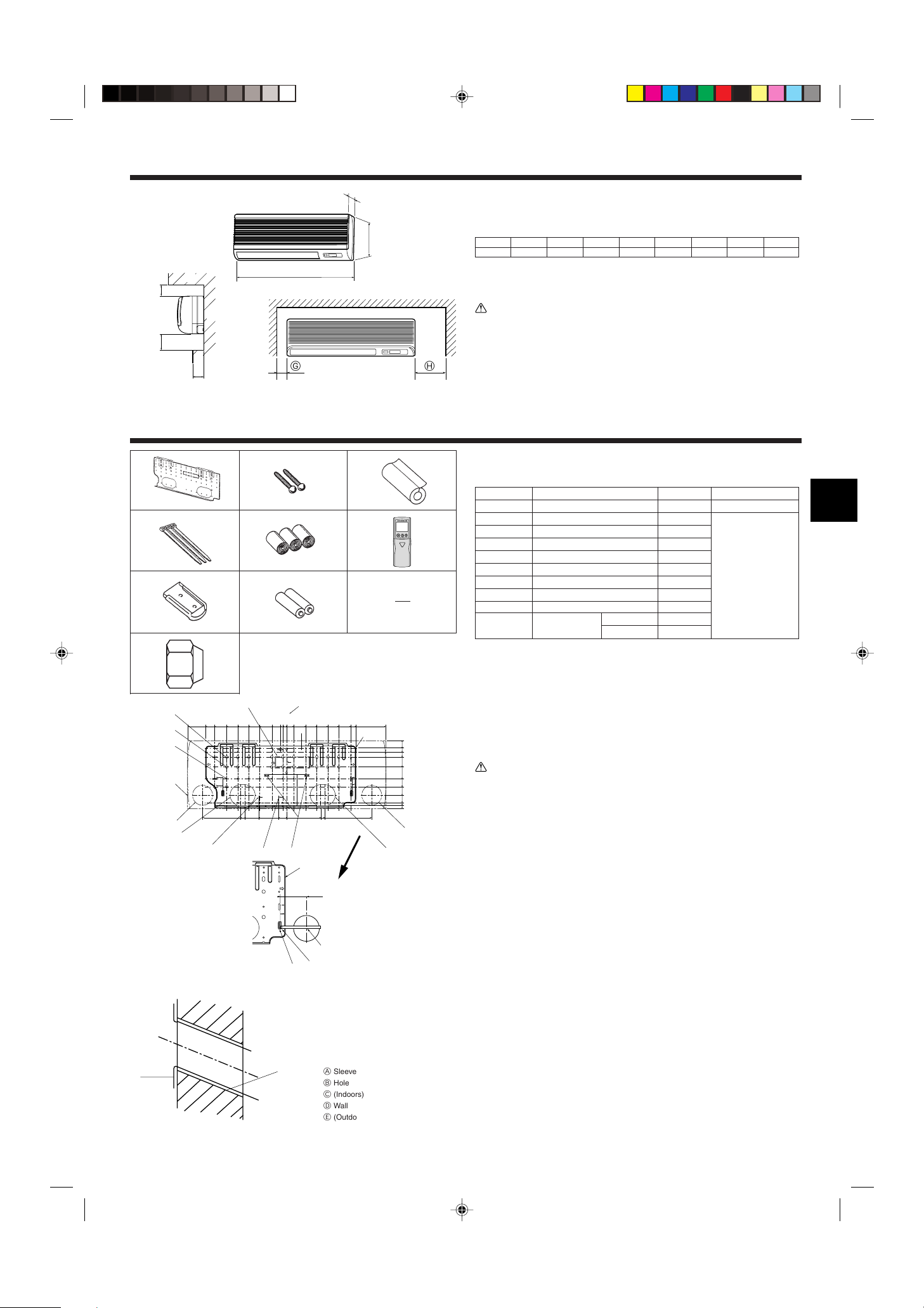
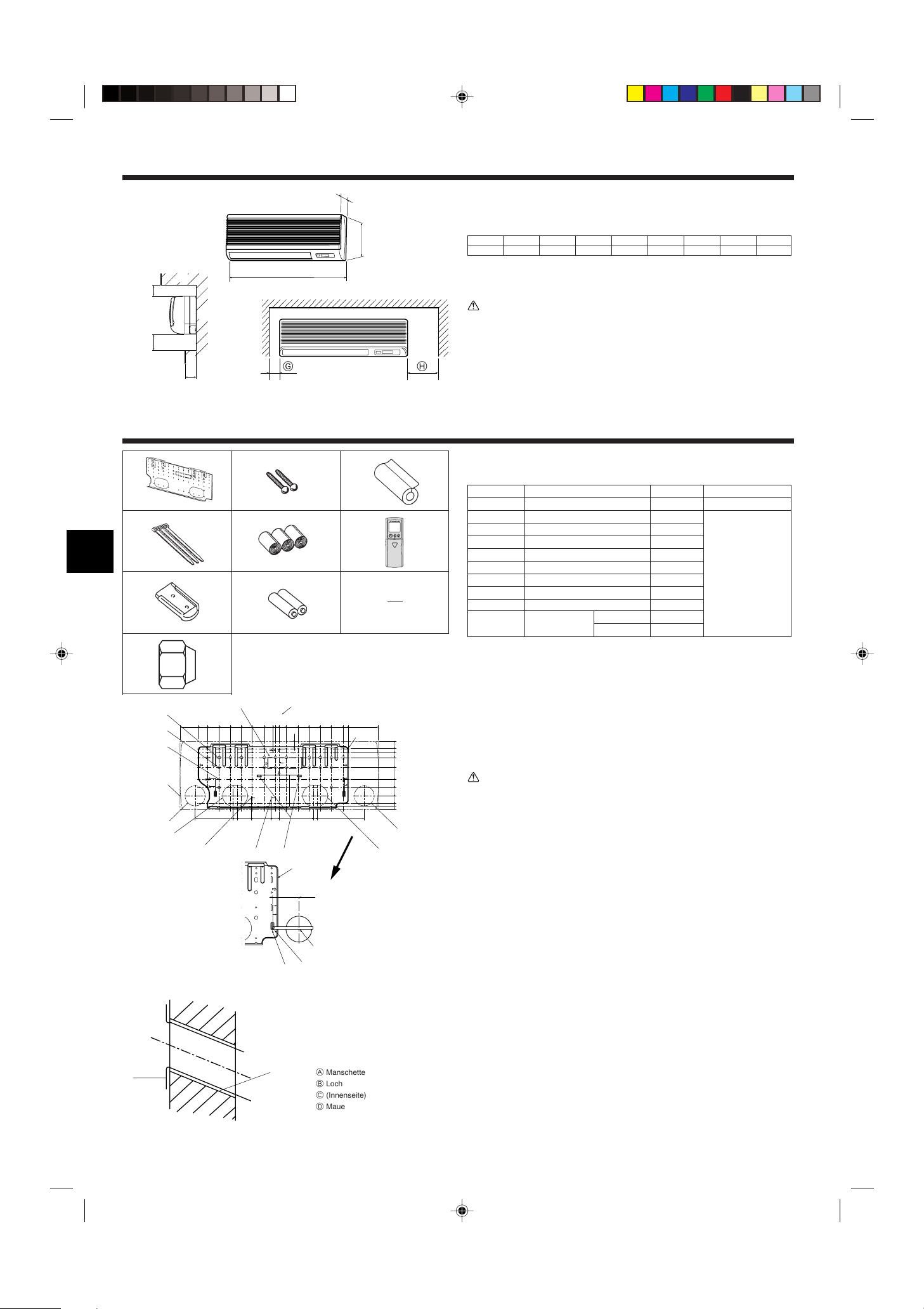
2.1. Outline dimensions (Indoor unit) (Fig. 2-1)
Select a proper position allowing the following clearances for installation and maintenance.
(mm)
Models W D H AE FGH
35, 50 990 235 340 Min. 30 Max. 130 Min. 180 Min. 50 Min. 150
B Ceiling
C Wall
D Furnishing, etc
Warning:
Mount the indoor unit on a ceiling strong enough to withstand the weight of the
unit.
2.2. Outline dimensions (Outdoor unit)
Refer to the outdoor unit installation manual.
1
2
3
3.1. Check the indoor unit accessories (Fig. 3-1)
The indoor unit should be supplied with the following accessories.
PART NUMBER
1 Mount board 1
4
5
6
2 Tapping screw 4 × 35 12
ACCESSORY QUANTITY
LOCATION OF SETTING
Fix at the back of the unit
3 Pipe cover 1
4 Band 3
5 Felt tape 3
7
8
9
6 Wireless remote controller 1
7 Remocon holder 1
Set inside the unit
8 Alkali batteries (size AAA) 2
9 Mount piece 1
0 Flare nut
0
RP35, 50
P35, 50 0
2 (ø9.52, ø15.88)
Fig. 3-1
(mm)
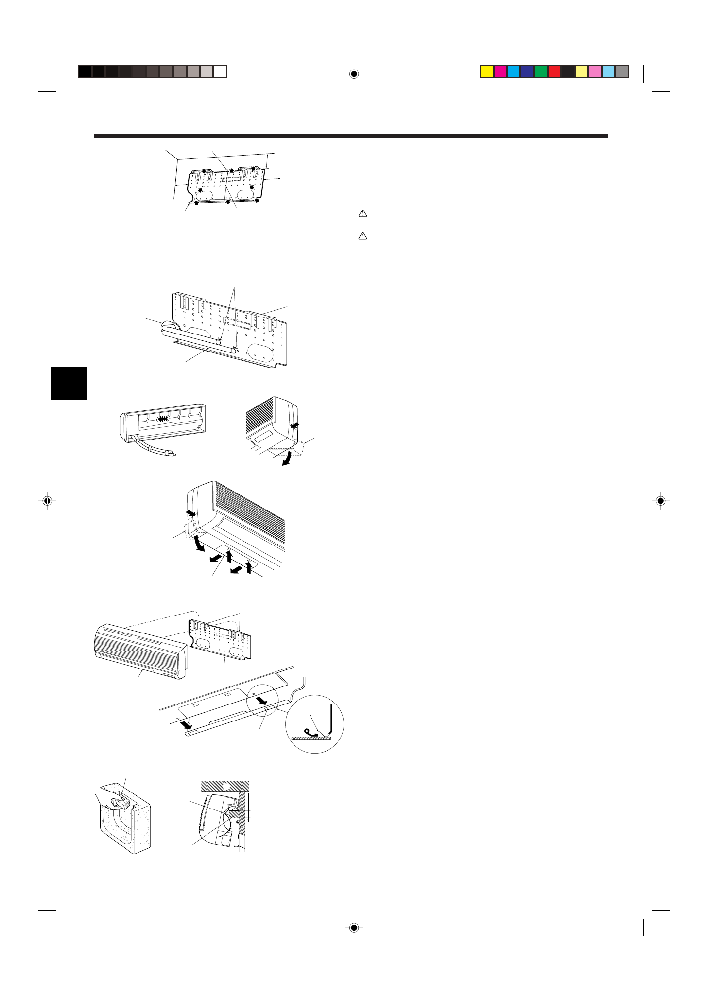
3.2. Installing the wall mounting fixture (Fig. 3-2)
3.2.1. Setting the wall mounting fixture and piping positions
s Using the wall mounting fixture, determine the unit’s installation position
and the locations of the piping holes to be drilled.
Warning:
Before drilling a hole in the wall, you must consult the building contractor.
A Supporting piece J Bottom right pipe slot (ø90)
B Mount board K Bottom right pipe slot knockout hole
C Main body L Liquid pipe flare connection position
D Slot (6-11 × 20) M Gas pipe flare connection position
E Unit center N Level setting standard
F Bolt hole (14-ø14) V Insert scale.
G Tapping hole (49-ø5) Y Hole centre
H Bottom left pipe slot (ø90) Z Align the scale with the line.
I Bottom left pipe slot knockout hole
Fig. 3-2
3.2.2. Drilling the piping hole (Fig. 3-3)
s Use a core drill to make a hole of 90-100 mm diameter in the wall in the
piping direction, at the position shown in the diagram to the left.
s The hole should incline so that the outside opening is lower than the inside
opening.
A Sleeve
B Hole
C (Indoors)
D Wall
E (Outdoors)
s Insert a sleeve (with a 90 mm diameter and purchased locally) through the
hole.
Note:
The purpose of the hole’s inclination is to promote drain flow.
Fig. 3-3
3
3. Installing the indoor unit
1
D
2
B
A
C
A
B
D
C
a
A
b
a
a
A
B
b
b
A
B
C
B
A
A
30~40
C
A
B
Fig. 3-4
Fig. 3-5
A Min. 140 mm
B Min. 300 mm
C Min. 55 mm
D Mount board
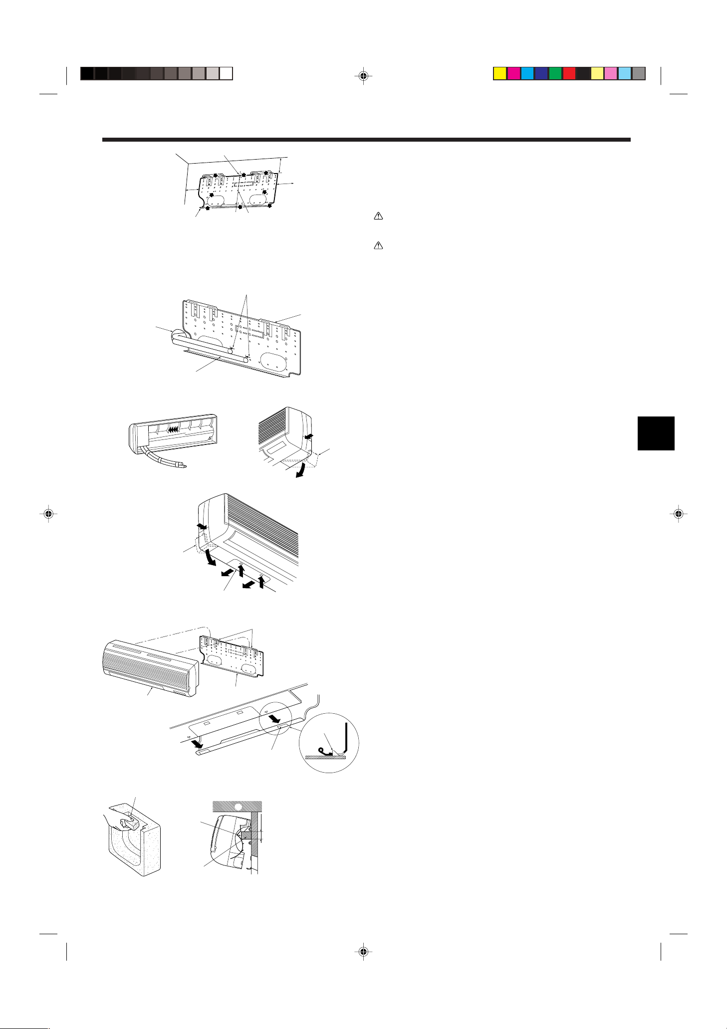
3.2.3. Installing the wall mounting fixture
s Since the indoor unit weighs near 30 kg, selection of the mounting location
requires thorough consideration. If the wall does not seem to be strong
enough, reinforce it with boards or beams before installation.
s The mounting fixture must be secured at both ends and at the centre, if
possible. Never fix it at a single spot or in any nonsymetrical way.
(If possible, secure the fixture at all the positions marked with a bold arrow.)
(Fig. 3-4)
Warning:
If possible, secure the fixture at all positions indicated with a bold arrow.
Caution:
• The unit body must be mounted horizontally.
• Fasten at the holes marked with ▲ as shown by the arrows.
1 Fasten a thread to the hole.
2 The level can be easily obtained by hanging a weight from the string and aligning the string
with the mark.
3.3. When embedding pipes into the wall (Fig. 3-5)
• The pipes are on the bottom left.
• When the cooling pipe, drain pipes internal/external connection lines etc are to be
embedded into the wall in advance, the extruding pipes etc, may have to be bent
and have their length modified to suit the unit.
• Use marking on the mount board as a reference when adjusting the length of the
embedded cooling pipe.
• During construction, give the length of the extruding pipes etc some leeway.
A Mount board
B Reference marking for flare connection
C Through hole
D On-site piping
Fig. 3-6
Fig. 3-7
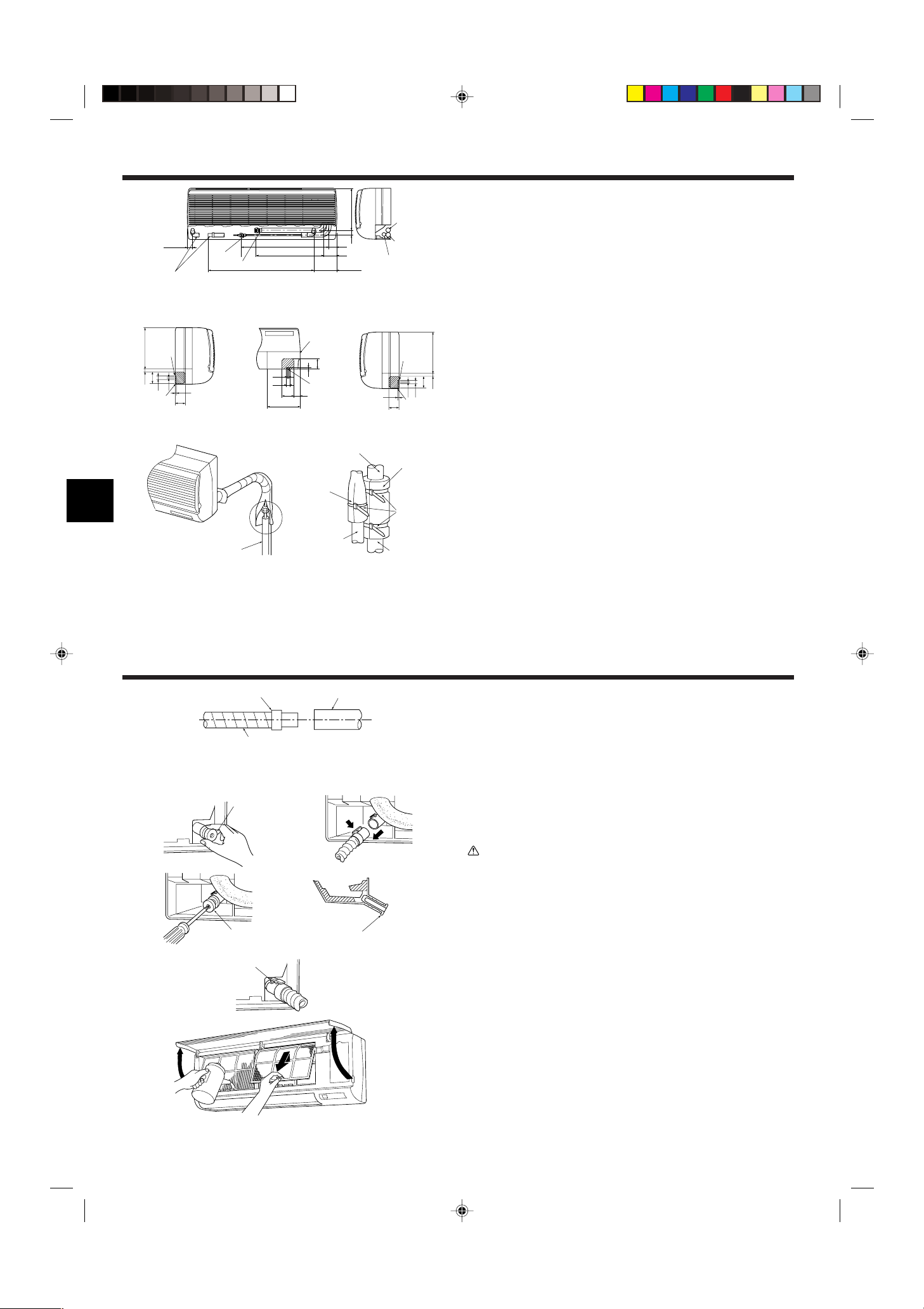
3.4. Preparing the indoor unit
Rear, right and lower piping (Fig. 3-6)
1. Bind the cooling pipe and drain pipe together.
• Bind the pipes together with vinyl tape at three or more points. This will facilitate
passing the pipes through the wall.
2. Remove the corner box and knock out the knockout holes as necessary.
• Remove the corner box by pushing in a downward direction b, while at the same
time, pressing in the upper side part of the corner box a.
A Corner box
B Under cover
Left and left rear piping (Fig. 3-7)
1. Remove the under cover.
• Remove the under cover by sliding it towards the rear of the unit b, while at the
same time, pressing the two points marked by arrow heads a.
2. Remove the corner box and knock out the knockout holes as necessary.
3.5. Mounting the indoor unit
1. Affix the mounting plate to the wall.
2. Hang the indoor unit on the two hooks positioned on the upper part of the mount-
ing plate.
Rear, right and lower piping (Fig. 3-8)
3. Affix the indoor unit.
4. After connecting the pipes, put the corner box back to where it was (follow the
removal steps backwards).
A Square hole
B Hooks
Fig. 3-8
Left and left rear piping (Fig. 3-9)
(mm)
Fig. 3-9
3. Cut out a mounting piece from the packaging material.
4. Pull the indoor unit up towards yourself as shown in the figure below and slide the
mounting piece in to the mounting plate using the mounting piece setting marks
as reference.
5. After connecting the pipes and wiring, put the under cover back to where it was,
and remove the mounting piece and affix the indoor unit as shown in the left
figure.
6. Put the corner box back to where it was.
A Mounting piece
B Ceiling
C Rib
4
4. Installing the refrigerant piping
90° ±0.5°
øA
R0.4~R0.8
A
45°±2°
B
C
D
A
A
B
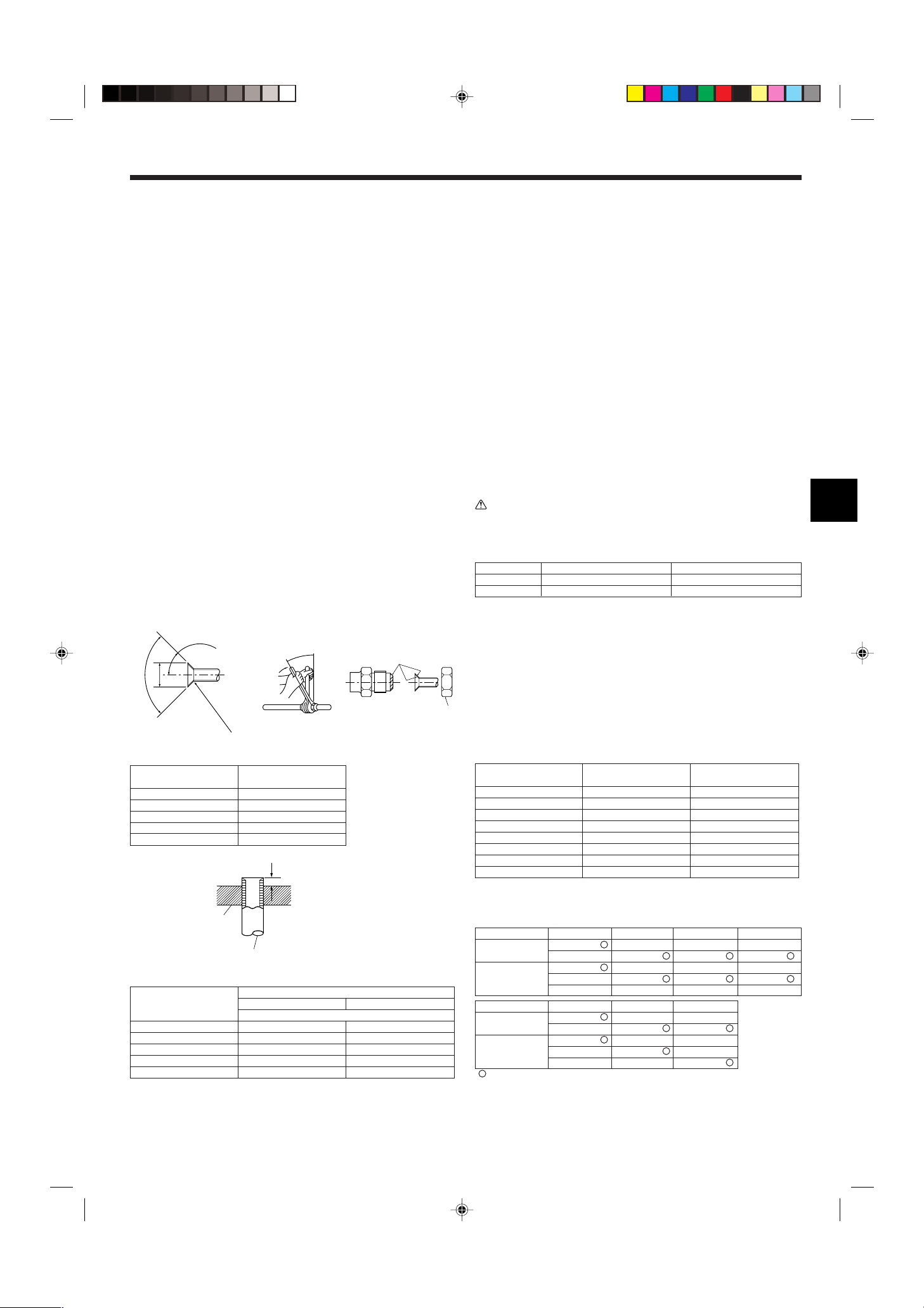
4.1. Precautions
4.1.1. For devices that use R407C refrigerant
• Do not use the existing refrigerant piping.
• Do not use crushed, misshapen, or discolored tubing. The inside of the tub-
ing should be clean and free from harmful sulfuric compounds, oxidants,
dirt, debris, oils and moisture.
• Store the piping to be used during installation indoors and keep both ends of
the piping sealed until just before brazing.
• Use ester oil, ether oil or alkylbenzene (small amount) as the refrigerator oil
to coat flares and flange connections.
• Use liquid refrigerant to fill the system.
• Do not use a refrigerant other than R407C.
• Use a vacuum pump with a reverse flow check valve.
• Do not use the tools that are used with conventional refrigerants.
• Do not use a charging cylinder.
• Be especially careful when managing the tools.
• Do not use commercially available dryers.
4.1.2. For devices that use R410A refrigerant
• Use ester oil, ether oil, alkylbenzene oil (small amount) as the refrigeration oil
applied to the flared sections.
• Use C1220 copper phosphorus, for copper and copper alloy seamless pipes,
to connect the refrigerant pipes. Use refrigerant pipes with the thicknesses
specified in the table to the below. Make sure the insides of the pipes are
clean and do not contain any harmful contaminants such as sulfuric compounds, oxidants, debris, or dust.
Warning:
When installing or moving the air conditioner, use only the specified refrigerant (R410A) to charge the refrigerant lines. Do not mix it with any other refrigerant and do not allow air to remain in the lines. Air enclosed in the lines can
cause pressure peaks resulting in a rupture and other hazards.
RP35, 50 RP60-140
Liquid pipe ø6.35 thickness 0.8 mm ø9.52 thickness 0.8 mm
Gas pipe ø12.7 thickness 0.8 mm ø15.88 thickness 1.0 mm
• Do not use pipes thinner than those specified above.
Fig. 4-1
A Flare cutting dimensions
Copper pipe O.D. Flare dimensions
(mm) øA dimensions (mm)
ø6.35 8.7 - 9.1
ø9.52 12.8 - 13.2
ø12.7 16.2 - 16.6
ø15.88 19.3 - 19.7
ø19.05 23.6 - 24.0
A Die
B Copper pipe
Fig. 4-2
Copper pipe O.D.
(mm)
ø6.35 (1/4") 0 - 0.5 1.0 - 1.5
ø9.52 (3/8") 0 - 0.5 1.0 - 1.5
ø12.7 (1/2") 0 - 0.5 1.0 - 1.5
ø15.88 (5/8") 0 - 0.5 1.0 - 1.5
ø19.05 (3/4") 0 - 0.5 1.0 - 1.5
Flare tool for R-22·R407C Flare tool for R410A
A (mm)
Clutch type
4.2. Connecting pipes (Fig. 4-1)
• When commercially available copper pipes are used, wrap liquid and gas pipes
with commercially available insulation materials (heat-resistant to 100 °C or more,
thickness of 12 mm or more).
• The indoor parts of the drain pipe should be wrapped with polyethylene foam insulation materials (specific gravity of 0.03, thickness of 9 mm or more).
• Apply thin layer of refrigerant oil to pipe and joint seating surface before tightening
flare nut.
• Use two wrenches to tighten piping connections.
• Use refrigerant piping insulation provided to insulate indoor unit connections. Insu-
late carefully.
B Flare nut tightening torque
Copper pipe O.D. Flare nut O.D. Tightening torque
(mm) (mm) (N·m)
ø6.35 17 14 - 18
ø6.35 22 34 - 42
ø9.52 22 34 - 42
ø12.7 26 49 - 61
ø12.7 29 68 - 82
ø15.88 29 68 - 82
ø15.88 36 100 - 120
ø19.05 36 100 - 120
C Apply refrigerating machine oil over the entire flare seat surface.
D Use correct flare nuts meeting the pipe size of the outdoor unit.
Available pipe size
RP35, 50 RP60 RP71
Liquid side
Gas side ø15.88 ø15.88
Liquid side
Gas side –ø15.88
: Factory flare nut attachment to the heat-exchanger.
ø6.35
ø9.52 ø9.52
ø12.7 –– –
–––ø19.05
P25
ø6.35
–ø9.52
ø12.7 ––
––ø19.05
ø6.35 ––
P35, 50, 60, 71
P100, 125, 140
––
ø9.52 ø9.52
ø15.88 ø15.88
ø9.52
–
RP100, 125, 140
5
A
B
C
A
a
b
A
A
B
4. Installing the refrigerant piping
A
B
C
D
E
F
G
E
D
B
C
A
C
B
D
F
35
449
581
28031
54
86
153
700
A
E
60
10
22
70
21
245
D
8
B
E
D
10
190
22
70 35
8
60
C
E
8
60
10
22
70
21 245
D
1
4.3. Positioning refrigerant and drain piping
1 Position of refrigerant and drain piping (Fig. 4-3)
• The drain pipe can be cut midway to meet the on-site conditions.
A (Total length of flexible hose) D Drain hose
B Liquid pipe E Left-side piping
C Gas pipe F Right-side piping
2 Determine the position of the knockout holes on the unit body. (Fig. 4-4)
Fig. 4-3
2
s Cut the knockout holes using a saw blade or an adequate knife.
Take care not to damage other parts of the unit.
• Remove the corner box and drill a knockout hole. If a hole is made without removing the box, the drain hose could be damaged.
A Left-side piping D Remote controller cable through hole
B Lower piping E Corner box
C Right-side piping
Fig. 4-4
4.4. Refrigerant piping (Fig. 4-5)
Indoor unit
1. Remove the flare nut and cap of the indoor unit.
2. Make a flare for the liquid pipe and gas pipe and apply refrigerating machine oil
(available from your local supplier) to the flare sheet surface.
3. Quickly connect the on site cooling pipes to the unit.
4. Wrap the pipe cover 3 that is attached to the gas pipe and make sure that the
connection join is not visible.
5. Wrap the pipe cover of the unit’s liquid pipe and make sure that it covers the
Fig. 4-5
insulation material of the on site liquid pipe.
6. Use the bands that are provided 4 to tighten both ends (15–20mm) of each pipe
cover 3.
A Cooling pipe and insulation (available from local supplier)
B Unit’s gas pipe E Bands 4
C Unit’s liquid pipe F On site gas pipe
D Pipe cover 3 G On site liquid pipe
5. Drainage piping work
Fig. 5-1
1
3
4
Fig. 5-2
5.1. Drainage piping work (Fig. 5-1)
• Drain pipes should have an inclination of 1/100 or more.
• For extension of the drain pipe, use a soft hose (inner dia. 15 mm) available on the
market or hard vinyl chloride pipe (VP-20/O.D. ø26 PVC TUBE). Make sure that
there is no water leakage from the connections.
• If the drain pipe passes indoors it must be covered with insulating material (foamed
polyethylene: specific gravity: 0.03, thickness: 9 mm or more) available on the market.
• Do not put the drain piping directly in a drainage ditch where sulphuric gas may be
generated.
2
• When piping has been completed, check that water flows from the end of the drain
pipe.
A Drain connection socket C Indoor unit’s drain hose
B On site drain pipe (VP-20)
Caution:
The drain pipe should be installed according to this Installation Manual to ensure correct drainage. Thermal insulation of the drain pipes is necessary to
prevent condensation. If the drain pipes are not properly installed and insulated, condensation may drip on the ceiling, floor or other possessions.
Preparing left and left rear piping (Fig. 5-2)
1 Remove the drain cap.
• Remove the drain cap by holding the bit that sticks out at the end of the pipe and
pulling.
A Drain cap
2 Remove the drain hose.
• Remove the drain hose by holding on to the base of the hose a (shown by arrow)
and pulling towards yourself b.
3 Insert the drain cap.
• Inser t a screwdriver etc into the hole at the end of the pipe and be sure to push to
the base of the drain cap.
4 Insert the drain hose.
• Push the drain hose until it is at the base of the drain box connection outlet.
• Please make sure the drain hose hook is fastened properly over the extruding drain
box connection outlet.
B Hooks
Remove the side panel of the indoor unit on the drain side. Pour water in the drain
pan and check that it comes out the drain pipe end. After confirmation, reinstall the
side panel.
6
B
C
D
E
NL
S2 S3S1
A
6. Electrical work
S1
S2
L
N
1
2
S1
S2
S3
S3
AB C
D
E
F
G
S1
S2
L
N
1
2
S1
S2
S3
1
2
S1
S2
S3
S3
1
2
S1
S2
S3
1
2
S1
S2
S3
ABC
D
E
F
GGGG
S1
S2
L
N
1
2
L
N
S1
S2
S3
S3
ABC
DG
H
E
F
BC
S1
S2
L
N
1
2
L
N
S1
S2
S3
1
2
L
N
S1
S2
S3
1
2
L
N
S1
S2
S3
S3
ABC
D
E
C
GGG
BH
F
Fig. 6-1
6.1.1. Indoor unit power supplied from outdoor unit
The following connection patterns are available.
The outdoor unit power supply patterns vary on models.
<For models without heater>
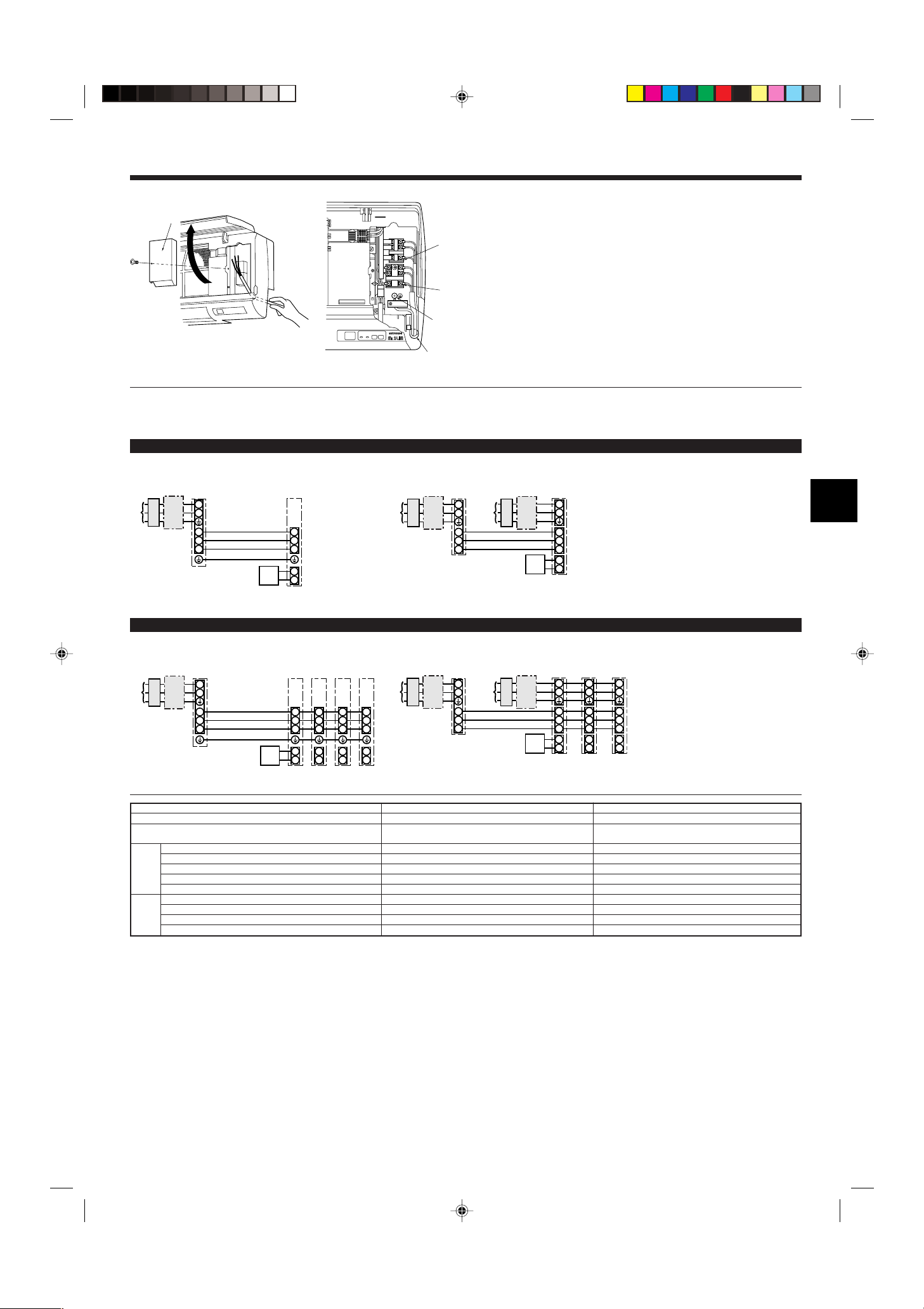
6.1. Indoor unit (Fig. 6-1)
1. Remove the corner box.
2. Install each wire into the unit.
3. Open the front grill, remove 1 tapping screw and remove the terminal block cover.
4. Connect each wire properly to the terminal block.
• In consideration of future servicing, please leave some leeway for the wiring length.
5. Put all the parts back the way they were.
6. Use a clamp from the bottom of the electric parts box to fasten each wire.
1:1 System
<For models with heater>
A Terminal block cover
B Terminal block for Indoor/outdoor connecting
C Terminal block for heater (PKH models)
D Earth point
E Clamp
A Outdoor unit power supply
B Earth leakage breaker
C Wiring circuit breaker or isolating switch
D Outdoor unit
E Indoor unit/outdoor unit connecting cords
F Remote controller
G Indoor unit
H Heater power supply
* Affix a label A that is included with the manuals near each wiring diagram for the indoor and outdoor units.
Simultaneous twin/triple/four system
<For models without heater>
* Affix a label A that is included with the manuals near each wiring diagram for the indoor and outdoor units.
Indoor unit model
Indoor unit power supply (Heater)
Indoor unit input capacity (Heater)
Main switch (Breaker)
Indoor unit power supply (Heater)
Indoor unit power supply (Heater) earth
)
2
Indoor unit-Outdoor unit
(mm
Wiring
Indoor unit-Outdoor unit
Wire No. × size
Remote controller-Indoor unit *3
Indoor unit (Heater) L-N *4
earth *2
Indoor unit-Outdoor unit S1-S2 *4
Indoor unit-Outdoor unit S2-S3 *4
rating
Circuit
Remote controller-Indoor unit *4
*1. A breaker with at least 3 mm contact separation in each pole shall be provided. Use non-fuse breaker (NF) or earth leakage breaker (NV).
*2. <For 25-140 outdoor unit application>
Max. 45 m
If 2.5 mm2 used, Max. 50 m
If 2.5 mm2 used and S3 separated, Max. 80 m
For PUHZ-RP100/125/140 YHA application, use shield wires. The shield part must be grounded with the indoor unit OR the outdoor unit, NOT with both.
<For 200/250 outdoor unit application>
Max. 18 m
If 2.5 mm2 used, Max. 30 m
If 4 mm2 used and S3 separated, Max. 50 m
If 6 mm2 used and S3 separated, Max. 80 m
*3. The 10 m wire is attached in the remote controller accessory. Max. 500 m
*4. The figures are NOT always against the ground.
S3 terminal has DC 24 V against S2 terminal. However between S3 and S1, these terminals are not electrically insulataed by the transformer or other device.
Notes: 1. Wiring size must comply with the applicable local and national code.
2. Power supply cords and Indoor unit/Outdoor unit connecting cords shall not be lighter than polychloroprene sheathed flexible cord. (Design 245 IEC 57)
3. Install an earth longer than other cables.
<For models with heater>
*1
*2
A Outdoor unit power supply
B Earth leakage breaker
C Wiring circuit breaker or isolating switch
D Outdoor unit
E Indoor unit/outdoor unit connecting cords
F Remote controller
G Indoor unit
H Heater power supply
PKA PKH
– ~/N (single), 50 Hz, 230 V
16 A–
– 2 × Min. 1.5
– 1 × Min. 1.5
3 × 1.5 (Polar) 3 × 1.5 (Polar)
1 × Min. 1.5 –
––
– AC 230 V
AC 230 V AC 230 V
DC 24 V DC 24 V
DC 12 V DC 12 V
7
6. Electrical work
S1
S2
L
N
1
2
L
N
S1
S2
S3
S3
A
CB
D
JEB
C
F
G
H
S1
S2
L
N
1
2
L
N
S1
S2
S3
1
2
L
N
S1
S2
S3
1
2
L
N
S1
S2
S3
1
2
L
N
S1
S2
S3
S3
ABC
D
E
JBC
F
H
GGGG
ON
OFF 1 2
(SW8)
3
S1
S2
S3
L
N
BLUE
BLUE
YELLOW
YELLOW
CND
CND
ORANGE
CND
ORANGE
S1
S2
S3
L
N
YELLOW
BLUE
BLUE
YELLOW
CND
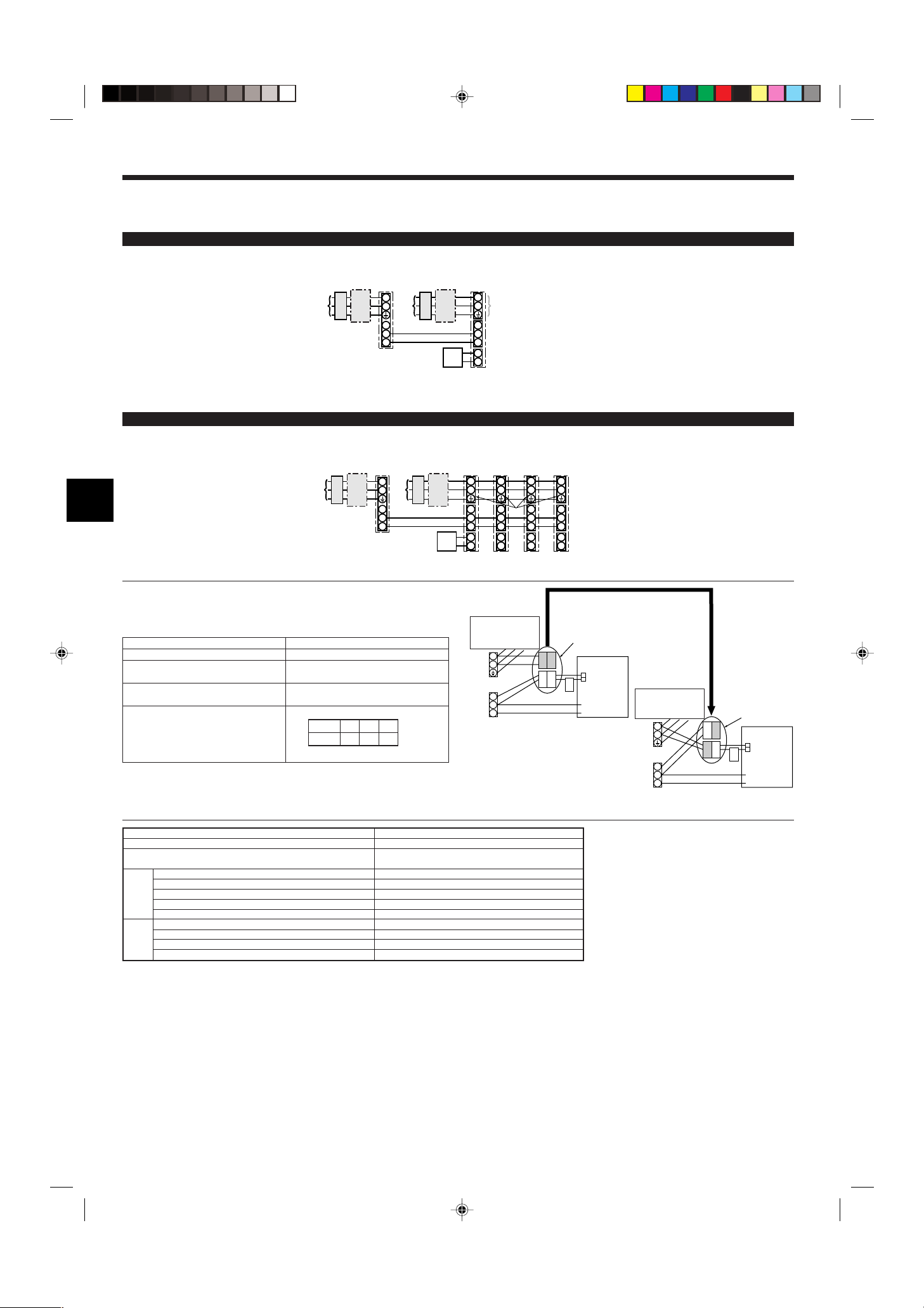
6.1.2. Separate indoor unit/outdoor unit power supplies (For PUHZ application only)
The following connection patterns are available.
The outdoor unit power supply patterns vary on models.
1:1 System
<For models without heater>
* The optional wiring replacement kit is required.
* Affix a label B that is included with the manuals near each wiring diagram for the indoor and outdoor units.
Simultaneous twin/triple/four system
<For models without heater>
* The optional wiring replacement kits are required.
A Outdoor unit power supply
B Earth leakage breaker
C Wiring circuit breaker or isolating switch
D Outdoor unit
E Indoor unit/outdoor unit connecting cords
F Remote controller
G Indoor unit
H Option
J Indoor unit power supply
A Outdoor unit power supply
B Earth leakage breaker
C Wiring circuit breaker or isolating switch
D Outdoor unit
E Indoor unit/outdoor unit connecting cords
F Remote controller
G Indoor unit
H Option
J Indoor unit power supply
* Affix a label B that is included with the manuals near each wiring diagram for the indoor and outdoor units.
If the indoor and outdoor units have separate power supplies, refer to the table at the
below. If the optional wiring replacement kit is used, change the indoor unit electrical
box wiring refering to the figure in the right and the DIP switch settings of the outdoor
unit control board.
Indoor unit specifications
Indoor power supply terminal kit (option)
Indoor unit electrical box connector connection change
Label affixed near each wiring diagram
for the indoor and outdoor units
Required
Required
Required
Outdoor unit DIP switch settings (when
using separate indoor unit/outdoor unit
power supplies only)
Electric heater
(For models with
heater)
Indoor unit power supplied from outdoor unit
(when shipped from factory)
Connectors (connections when shipped
from the factory are for indoor unit power
supplied from outdoor unit)
Indoor unit
control board
Electric heater
(For models with
heater)
* There are three types of labels (labels A, B, and C). Affix the appropriate labels to
the units according to the wiring method.
Separate indoor unit/outdoor unit power
supplies
Indoor unit model
Indoor unit power supply
Indoor unit input capacity
Main switch (Breaker)
Indoor unit power supply
Indoor unit power supply earth
)
2
Indoor unit-Outdoor unit *2
(mm
Wiring
Indoor unit-Outdoor unit earth
Wire No. × size
Remote controller-Indoor unit *3
*1
Indoor unit L-N *4
Indoor unit-Outdoor unit S1-S2 *4
Indoor unit-Outdoor unit S2-S3 *4
rating
Circuit
Remote controller-Indoor unit *4
*1. A breaker with at least 3 mm contact separation in each pole shall be provided. Use non-fuse breaker (NF) or earth leakage breaker (NV).
*2. Max. 120 m
PKA
~/N (single), 50 Hz, 230 V
16 A
2 × Min. 1.5
1 × Min. 1.5
2 × Min. 0.3
–
–
AC 230 V
–
DC 24 V
DC 12 V
For PUHZ-RP100/125/140 YHA application, use shield wires. The shield part must be grounded with the indoor unit OR the outdoor unit, NOT with both.
*3. The 10 m wire is attached in the remote controller accessory. Max. 500 m
*4. The figures are NOT always against the ground.
Notes: 1. Wiring size must comply with the applicable local and national code.
2. Power supply cords and indoor unit/outdoor unit connecting cords shall not be lighter than polychloroprene sheathed flexible cord. (Design 245 IEC 57)
3. Install an earth longer than other cables.
If the indoor and
outdoor units have
separate power
supplies, change the
connections of the
connectors as shown
in the following
figure.
Connectors
Indoor unit
control board
8
6. Electrical work
MODEL SELECT
MODEL SELECT
30
46
30
30120
83.5
A
B
C
F
A
H
C
D
E
G
I
I
I
H
B
A
AB TB6
B
ON/OFF TEMP
FAN
VANE
TEST RUN
AUTO STOP
AUTO START
h
min
LOUVER
MODE
CHECK
RESETSET CLOCK
MODEL SELECT
2,4
3
A
J
H
B
1
C
A
2
ON
OFF
STAND
BY
COOL HEAT
D
Fig. 6-2
B-1. B-2.
Fig. 6-3
Fig. 6-4
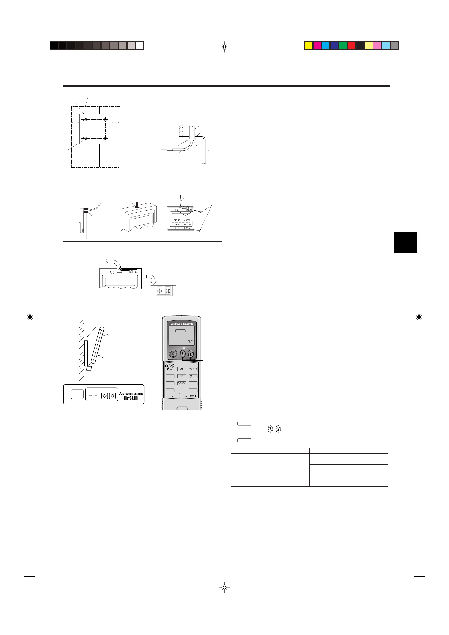
6.2. Remote controller
6.2.1. For wired remote controller
1) Installing procedures
(1) Select an installing position for the remote controller. (Fig. 6-2)
The temperature sensors are located on both remote controller and indoor unit.
s Procure the following parts locally:
Two piece switch box
Thin copper conduit tube
Lock nuts and bushings
A Remote controller profile
B Required clearances surrounding the remote controller
C Installation pitch
(2) Seal the service entrance for the remote controller cord with putty to prevent pos-
sible invasion of dew drops, water, cockroaches or worms. (Fig. 6-3)
A For installation in the switch box:
B For direct installation on the wall select one of the following:
• Prepare a hole through the wall to pass the remote controller cord (in order to run
the remote controller cord from the back), then seal the hole with putty.
• Run the remote controller cord through the cut-out upper case, then seal the cutout notch with putty similarly as above.
B-1. To lead the remote controller cord from the back of the controller:
B-2. To run the remote controller cord through the upper portion:
(3) For direct installation on the wall
C Wall
D Conduit
E Lock nut
F Bushing
G Switch box
H Remote controller cord
I Seal with putty
J Wood screw
2) Connecting procedures (Fig. 6-4)
1 Connect the remote controller cord to the terminal block.
A To TB5 on the indoor unit
B TB6 (No polarity)
3) Two remote controllers setting
If two remote controllers are connected, set one to “Main” and the other to “Sub”. Fo r
setting procedures, refer to “Function selection of remote controller” in the operation
manual for the indoor unit.
Fig. 6-5
Fig. 6-6
6.2.2. For wireless remote controller
1) Installation area
• Area in which the remote controller is not exposed to direct sunshine.
• Area in which there is no nearby heating source.
• Area in which the remote controller is not exposed to cold (or hot) winds.
• Area in which the remote controller can be operated easily.
• Area in which the remote controller is beyond the reach of children.
2) Installation method (Fig. 6-5)
1 Attach the remote controller holder to the desired location using two tapping screws.
2 Place the lower end of the controller into the holder.
A Remote controller
B Wall
C Display panel
D Receiver
• The signal can travel up to approximately 7 meters (in a straight line) within 45
degrees to both right and left of the center line of the receiver.
3) Setting (Fig. 6-6)
1 Insert batteries.
2 Press the SET button with something sharp at the end.
3 Press the temp
4 Press the SET button with something sharp at the end.
blinks and Model No. is lighted.
button to set the Model No.
and Model No. are lighted for three seconds, then turned off.
Indoor Outdoor A Model No.
PLH, PCH, PKH (35, 50) PUH 001
PLA, PCA, PKA (35, 50)
PUH, PUHZ, SUZ 001
PU 033
PKH (60, 71, 100) PUH 003
PKA (60, 71, 100)
PUH, PUHZ, SUZ 003
PU 035
9
PAR-21MAA
ON/OFF
FILTER
CHECK
OPERATION
CLEAR
TEST
TEMP.
MENU
BACK DAY
MONITOR/SET
CLOCK
ON/OFF
A
B
DC
G
E
F
4
1
213 4
1 2
MODEL SELECT
min
CHECK
CHECK
ON/OFF TEMP
FAN
VANE
TEST RUN
AUTO STOP
AUTO START
h
min
LOUVER
MODE
CHECK
RESETSET CLOCK
CHECK
E
C,D
F
A
B
CHECK
CHECK
6. Electrical work
ON/OFF TEMP
FAN
VANE
TEST RUN
AUTO STOP
AUTO START
h
min
LOUVER
MODE
CHECK
RESETSET CLOCK
MODEL SELECT
1,4
3
A
2
CHECK
CHECK
h
min
h
h
Fig. 6-7
Fig. 6-8
1
⁄ Mode number
2
⁄ Setting number
3
⁄ Refrigerant address
4
⁄ Unit number
4) Assigning a remote controller to each unit (Fig. 6-7)
Each unit can be operated only by the assigned remote controller.
Make sure each pair of an indoor unit PC board and a remote controller is assigned
to the same pair No.
5) Wireless remote controller pair number setting operation
1 Press the SET button with something sharp at the end.
Start this operation from the status of remote controller display turned off.
blinks and Model No. is lighted.
2 Press the
button twice continuously.
Pair No. “0” blinks.
3 Press the temp
button to set the pair number you want to set.
4 Press the SET button with something sharp at the end.
Set pair number is lighted for three seconds then turned off.
A Pair No. of wireless remote controller Indoor PC board
0 Factory setting
1 Cut J41
2 Cut J42
3–9 Cut J41, J42
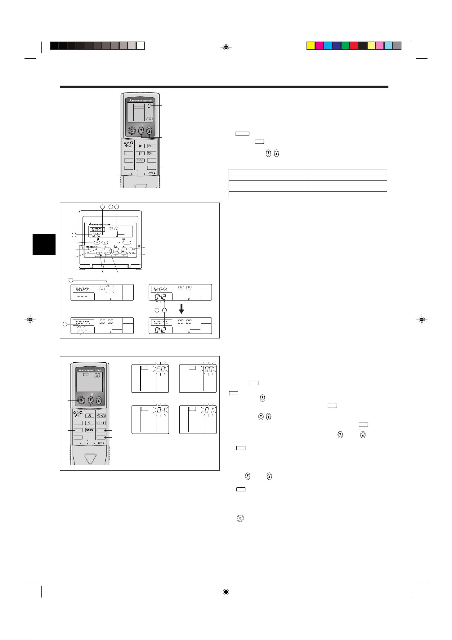
6.3. Function settings
6.3.1 Function setting on the unit (Selecting the unit functions)
1) For wired remote controller (Fig. 6-8)
Changing the power voltage setting
• Be sure to change the power voltage setting depending on the voltage used.
1 Go to the function setting mode.
Switch OFF the remote controller.
Press the A and B buttons simultaneously and hold them for at least 2
seconds. FUNCTION will start to flash.
2 Use the C button to set the refrigerant address (3) to 00.
3 Press D and [--] will start to flash in the unit number (4) display.
4 Use the C button to set the unit number (4) to 00.
5 Press the E MODE button to designate the refrigerant address/unit number. [--]
will flash in the mode number (1) display momentarily.
6 Press the F buttons to set the mode number (1) to 04.
7 Press the G button and the current set setting number (2) will flash.
Use the F button to switch the setting number in response to the power supply
voltage to be used.
Power supply voltage
8 Press the MODE button E and mode and the setting number (1) and (2) will
change to being on constantly and the contents of the setting can be confirmed.
9 Press the FILTER A and TEST RUN B buttons simultaneously for at least two
seconds. The function selection screen will disappear momentarily and the air
conditioner OFF display will appear.
240 V : setting number = 1
220 V, 230 V : setting number = 2
10
2) For wireless remote controller (Fig. 6-9)
1
2
Changing the power voltage setting
• Be sure to change the power voltage setting depending on the voltage used.
1 Go to the function select mode
Press the
button F twice continuously.
(Start this operation from the status of remote controller display turned off.)
is lighted and “00” blinks.
Press the temp
3
4
toward the receiver of the indoor unit and press the
button C once to set “50”. Direct the wireless remote controller
button A.
2 Setting the unit number
Press the temp
remote controller toward the receiver of the indoor unit and press the
button C and D to set the unit number “00”. Direct the wireless
button B.
3 Selecting a mode
Enter 04 to change the power voltage setting using the
C and D buttons.
Direct the wireless remote controller toward the receiver of the indoor unit and press
the
button A.
Current setting number: 1 = 1 beep (one second)
2 = 2 beeps (one second each)
3 = 3 beeps (one second each)
4 Selecting the setting number
Fig. 6-9
Use the
C and D buttons to change the power voltage setting to 01 (240 V).
Direct the wireless remote controller toward the sensor of the indoor unit and press
the
button A.
5 To select multiple functions continuously
Repeat steps 3 and 4 to change multiple function settings continuously.
6 Complete function selection
Direct the wireless remote controller toward the sensor of the indoor unit and press
the
button E.
Note:
Whenever changes are made to the function settings after installation or maintenance, be sure to record the changes with a mark in the “Setting” column of
the Function table.
6.3.2 Function setting on the remote controller
Refer to the indoor unit operation manual.
6. Electrical work
TEST RUN
TEST RUN
MODE
COOL
MODE
HEAT
FAN
VANE
ON/OFF TEMP
FAN
VANE
TEST RUN
AUTO STOP
AUTO START
h
min
LOUVER
MODE
CHECK
RESETSET CLOCK
TEST RUN
5
7
A
3,4
2
6
˚C
˚C
SIMPLE
PAR-21MAA
ON/OFF
FILTER
CHECK
OPERATION
CLEAR
TEST
TEMP.
MENU
BACK DAY
MONITOR/SET
CLOCK
ON/OFF
TEST RUN
COOL, HEAT
A
FCEDB
M
IH G
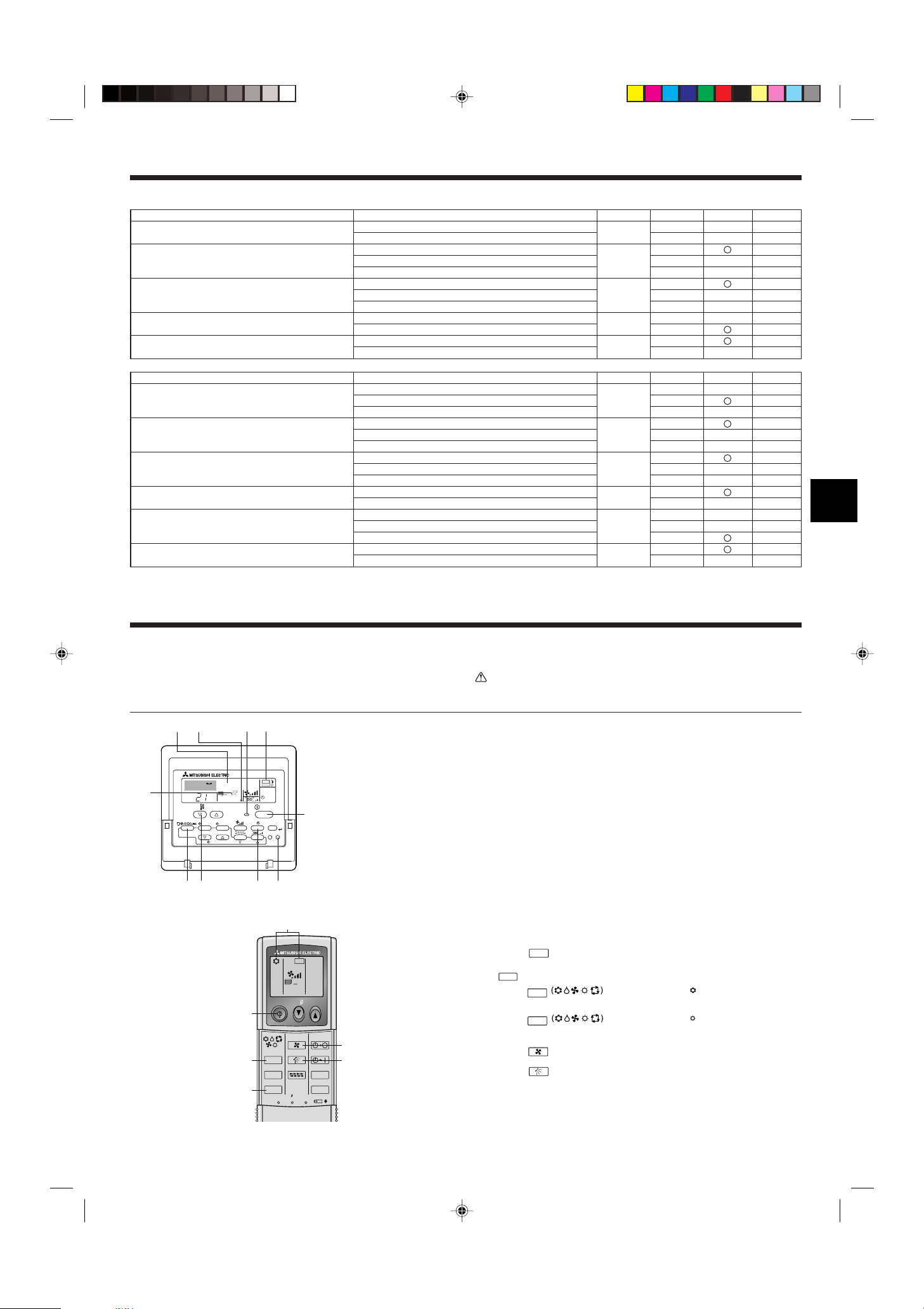
Function table
Select unit number 00
Mode
Power failure automatic recovery
Indoor temperature detecting
LOSSNAY connectivity
Power voltage
Auto mode (only for PUHZ)
Select unit numbers 01 to 03 or all units (AL [wired remote controller]/07 [wireless remote controller])
Mode
Filter sign
Fan speed
No. of air outlets
Installed options (high-performance filter)
Up/down vane setting
Energy saving air flow
(Heating mode)
*1 When the power supply returns, the air conditioner will start 3 minutes later.
*2 Power failure automatic recovery initial setting depends on the connecting outdoor unit.
Settings
Not available
Available *1
Indoor unit operating average
Set by indoor unit’s remote controller
Remote controller’s internal sensor
Not Supported
Supported (indoor unit is not equipped with outdoor-air intake)
Supported (indoor unit is equipped with outdoor-air intake)
240 V
220 V, 230 V
Energy saving cycle automatically enabled
Energy saving cycle automatically disabled
Settings
100Hr
2500Hr
No filter sign indicator
Standard (PLH/PLA)/Silent (PCH/PCA)
High ceiling 1
(PLH/PLA)/Standard (PCH/PCA)
High ceiling 2 (PLH/PLA)/High ceiling (PCH/PCA)
4 directions
3 directions
2 directions
Not supported
Supported
No vanes
Equipped with vanes (vanes angle setup 1)
Equipped with vanes (vanes angle setup 2)
Disabled
Enabled
Mode no. Setting no.
01
1*2
2*2
1
02 2
3
1
03 2
3
04
05
1
2
1
2
Mode no. Setting no.
1
07 2
3
1
08 2
3
1
09 2
3
10
1
2
1
11
2
3
12
1
2
Initial setting
Initial setting
setting
setting
7. Test run
7.1. Before test run
s After completing installation and the wiring and piping of the indoor and outdoor
units, check for refrigerant leakage, looseness in the power supply or control
wiring, wrong polarity, and no disconnection of one phase in the supply.
s Use a 500-volt megohmmeter to check that the resistance between the power
supply terminals and ground is at least 1.0 M
Fig. 7-1
ΩΩ
Ω.
ΩΩ
A ON/OFF button
B Test run display
C Indoor temperature liquid line
temperature display
D ON/OFF lamp
E Power display
F Error code display
Test run remaining time display
G Set temperature button
H Mode selection button
I Fan speed button
M TEST button
s Do not carry out this test on the control wiring (low voltage circuit) termi-
nals.
Warning:
Do not use the air conditioner if the insulation resistance is less than 1.0 M
ΩΩ
Ω.
ΩΩ
Insulation resistance
7.2. Test run
The following 3 methods are available.
7.2.1. Using wired remote controller (Fig. 7-1)
1 Turn on the power at least 12 hours before the test run.
2 Press the [TEST] button twice. ➡ “TEST RUN” liquid crystal display
3 Press the [Mode selection] button. ➡ Make sure that wind is blown out.
4 Press the [Mode selection] button and switch to the cooling (or heating) mode.
➡ Make sure that cold (or warm) wind is blown out.
5 Press the [Fan speed] button. ➡ Make sure that the wind speed is switched.
6 Check operation of the outdoor unit fan.
7 Release test run by pressing the [ON/OFF] button. ➡ Stop
8 Register a telephone number.
The telephone number of the repair shop, sales office, etc., to contact if an error
occurs can be registered in the remote controller. The telephone number will be
displayed when an error occurs. For registration procedures, refer to the operation
manual for the indoor unit.
7.2.2. Using wireless remote controller (Fig. 7-2)
1 Turn on the power to the unit at least 12 hours before the test run.
2 Press the
(Start this operation from the status of remote controller display turned off.)
A
3 Press the
cool air is blown out from the unit.
4 Press the
warm air is blown out from the unit.
5 Press the
6 Press the
7 Press the ON/OFF button to stop the test run.
button twice continuously.
and current operation mode are displayed.
button to activate
button to activate
mode, then check whether
mode, then check whether
button and check whether fan speed changes.
button and check whether the auto vane operates properly.
Note:
• Point the remote controller towards the indoor unit receiver while following
Fig. 7-2
steps 2 to 7.
• It is not possible to run the in FAN, DRY or AUTO mode.
11
CHECK
CHECK
h
7. Test run
ON/OFF TEMP
FAN
VANE
TEST RUN
AUTO STOP
AUTO START
h
min
LOUVER
MODE
CHECK
RESETSET CLOCK
CHECK
2
4
A
3
B
PAR-21MAA
ON/OFF
FILTER
CHECK
OPERATION
CLEAR
TEST
TEMP.
MENU
BACK DAY
MONITOR/SET
CLOCK
ON/OFF
ERROR CODE
ERROR CODE
ERROR CODE
C
B
A
B
F
E
E D
7.2.3. Using SW4 in outdoor unit
Refer to the outdoor unit installation manual.
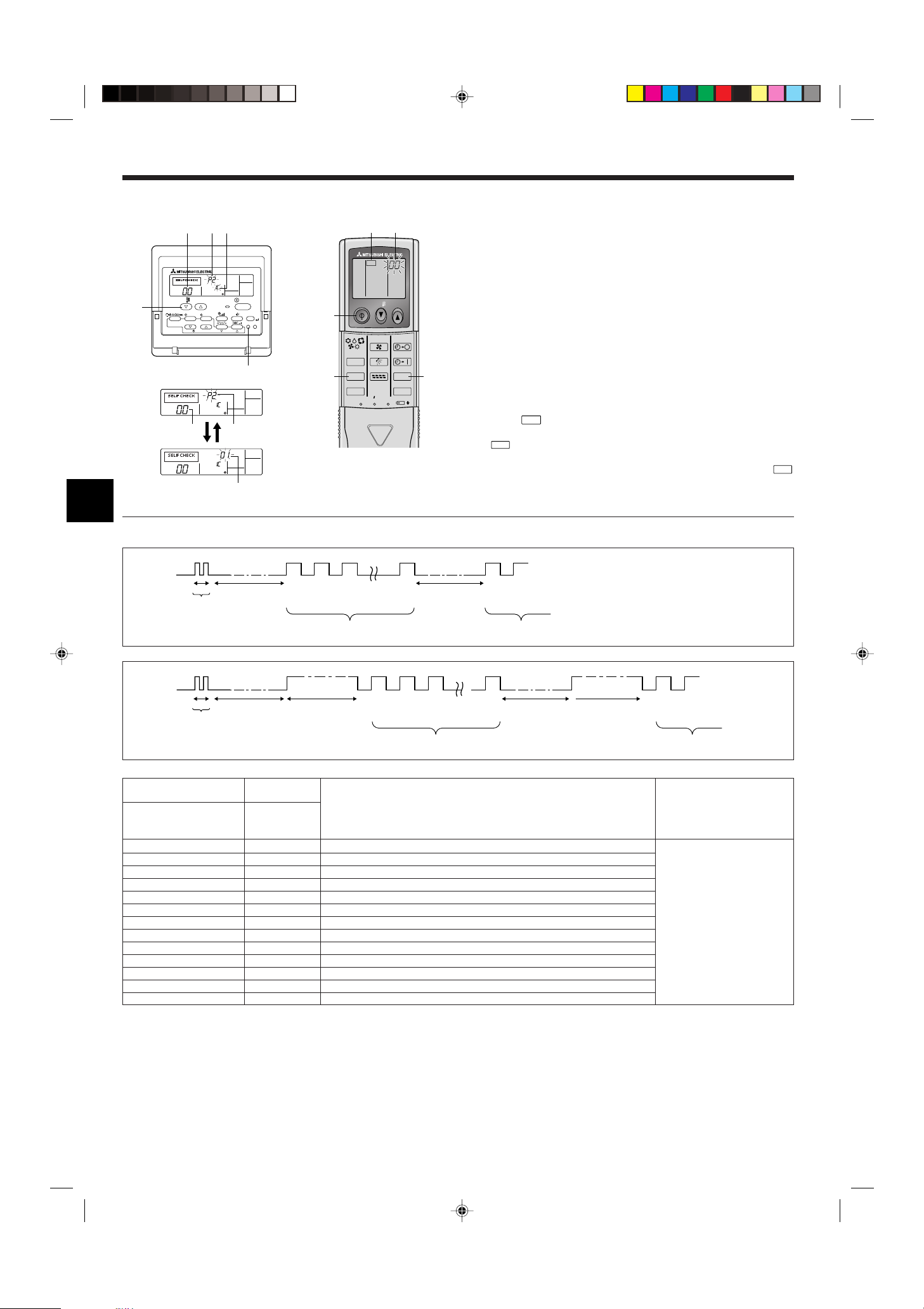
7.3. Self-check
7.3.1. Wired remote controller (Fig. 7-3)
1 Turn on the power.
2 Press the [CHECK] button twice.
3 Set refrigerant address with [TEMP] button if system control is used.
4 Press the [ON/OFF] button to stop the self-check.
A CHECK button
B Refrigerant address
C TEMP. button
D IC: Indoor unit
OC: Outdoor unit
E Check code
F Unit address
7.3.2. Wireless remote controller (Fig. 7-4)
1 Turn on the power.
2 Press the
(Start this operation from the status of remote controller display turned off.)
A
Fig. 7-4
B “00” begins to blink.
3 While pointing the remote controller toward the unit’s receiver, press the
button. The check code will be indicated by the number of times that the buzzer
sounds from the receiver section and the number of blinks of the operation lamp.
Fig. 7-3
4 Press the ON/OFF button to stop the self-check.
• Refer to the following tables for details on the check codes. (Wireless remote controller)
[Output pattern A]
Beeper sounds
OPERATION
INDICATOR
lamp flash
pattern
Beep
Self-check
starts
(Start signal
received)
Beep Beep Beep Beep Beep Beep
1st2nd3
Off
Approx. 2.5 sec.On0.5 sec.On0.5 sec.On0.5 sec.
Number of flashes/beeps in pattern indicates the check
code in the following table (i.e., n=5 for “P5”)
rd
th
n
On
0.5 sec.
Off
Approx. 2.5 sec.On0.5 sec.On0.5 sec.
1st2
Number of flashes/beeps in pattern indicates
the check code in the following table
[Output pattern B]
Beeper sounds
OPERATION
INDICATOR
lamp flash
pattern
Beep Beep Beep Beep Beep Beep Beep
th
n
On
0.5 sec.
Self-check
starts
(Start signal
received)
1st2nd3
Off
Approx. 2.5 sec.OnApprox. 3 sec.On0.5 sec.On0.5 sec.On0.5 sec.
Number of flashes/beeps in pattern indicates the check
code in the following table (i.e., n=5 for “P5”)
rd
[Output pattern A] Errors detected by indoor unit
Wireless remote controller
Wired remote
controller
Beeper sounds/OPERATION Symptom Remark
INDICATOR lamp flashes Check code
(Number of times)
1 P1 Intake sensor error
2 P2, P9 Pipe (Liquid or 2-phase pipe) sensor error
3 E6, E7 Indoor/outdoor unit communication error
4 P4 Drain sensor error
5 P5 Drain pump error
6 P6 Freezing/Overheating safeguard operation
7 EE Communication error between indoor and outdoor units
8 P8 Pipe temperature error
9 E4 Remote controller signal receiving error
10 ––
11 ––
12 Fb Indoor unit control system error (memory error, etc.)
No sound – – No corresponding
button twice.
begins to light.
nd
· · · Repeated
nd
1st2
Off
Approx. 2.5 sec.OnApprox. 3 sec.On0.5 sec.On0.5 sec.
Number of flashes/beeps in pattern indicates
the check code in the following table
· · · Repeated
12
7. Test run
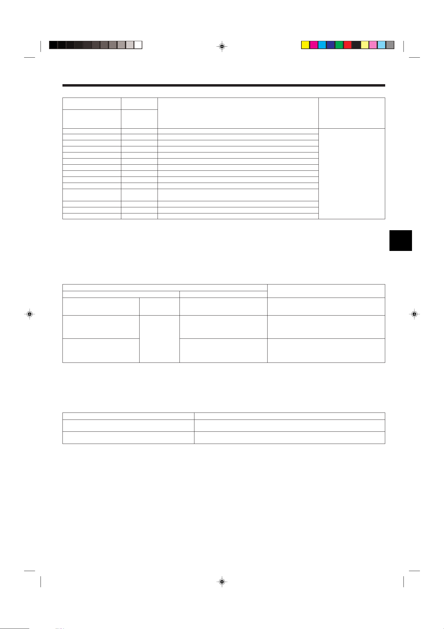
[Output pattern B] Errors detected by unit other than indoor unit (outdoor unit, etc.)
Wireless remote controller
Beeper sounds/OPERATION Symptom Remark
INDICATOR lamp flashes Check code
(Number of times)
1 E9 Indoor/outdoor unit communication error (Transmitting error) (Outdoor unit)
2 UP Compressor overcurrent interruption
3 U3, U4 Open/short of outdoor unit thermistors
4 UF Compressor overcurrent interruption (When compressor locked)
5 U2 Abnormal high discharging temperature/49C worked/insufficient refrigerant
6 U1, Ud Abnormal high pressure (63H worked)/Overheating safeguard operation
7 U5 Abnormal temperature of heat sink
8 U8 Outdoor unit fan safeguard stop
9 U6 Compressor overcurrent interruption/Abnormal of power module
10 U7 Abnormality of super heat due to low discharge temperature
11 U9, UH Abnormality such as overvoltage or voltage shortage and abnormal synchronous
12 ––
13 ––
14 Others Other errors (Refer to the technical manual for the outdoor unit.)
*1 If the beeper does not sound again after the initial two beeps to confirm the self-check start signal was received and the OPERATION INDICATOR lamp does not come on,
there are no error records.
*2 If the beeper sounds three times continuously “beep, beep, beep (0.4 + 0.4 + 0.4 sec.)” after the initial two beeps to confirm the self-check start signal was received, the
specified refrigerant address is incorrect.
• On wireless remote controller
The continuous buzzer sounds from receiving section of indoor unit.
Blink of operation lamp
• On wired remote controller
Check code displayed in the LCD.
• If the unit cannot be operated properly after the above test run has been performed, refer to the following table to remove the cause.
Wired remote controller LED 1, 2 (PCB in outdoor unit)
PLEASE WAIT
PLEASE WAIT → Error code
Display messages do not appear even
when operation switch is turned ON
(operation lamp does not light up).
Wired remote
controller
For about 2
minutes following
power-on
After about 2
minutes has
expired following
power-on
signal to main circuit/Current sensor error
Symptom
After LED 1, 2 are lighted, LED 2 is turned off,
then only LED 1 is lighted. (Correct operation)
Only LED 1 is lighted. → LED 1, 2 blink.
Only LED 1 is lighted. → LED 1 blinks twice,
LED 2 blinks once.
For details, check the LED display
of the outdoor controller board.
Cause
• For about 2 minutes following power-on, operation of the
remote controller is not possible due to system start-up. (Correct operation)
• Connector for the outdoor unit’s protection device is not connected.
• Reverse or open phase wiring for the outdoor unit’s power
terminal block (L1, L2, L3)
• Incorrect wiring between indoor and outdoor units (incorrect
polarity of S1, S2, S3)
• Remote controller wire short
On the wireless remote controller with condition above, following phenomena takes place.
• No signals from the remote controller are accepted.
• OPE lamp is blinking.
• The buzzer makes a short pipng sound.
Note:
Operation is not possible for about 30 seconds after cancellation of function selection. (Correct operation)
For description of each LED (LED 1, 2, 3) provided on the indoor controller, refer to the following table.
LED 1 (power for microcomputer) Indicates whether control power is supplied. Make sure that this LED is always lit.
LED 2 (power for remote controller) Indicates whether power is supplied to the remote controller. This LED lights only in the case of the
LED 3 (communication between indoor and outdoor units) Indicates state of communication between the indoor and outdoor units. Make sure that this LED is
indoor unit which is connected to the outdoor unit refrigerant address “0”.
always blinking.
13
TEST
MAINTENANCE
MENU
ON/OFF
COMP ON
x10 HOURS
COMP ON
x100 TIMES
COMP ON
CURRENT (A)
OUTDOOR UNIT
H·EXC. TEMP
OUTDOOR UNIT
OUTLET TEMP
OUTDOOR UNIT
OUTDOOR TEMP
INDOOR UNIT
INLET TEMP
INDOOR UNIT
H·EXC. TEMP
INDOOR UNIT
FILTER USE H
FILTER
TEST
ON/OFF
COOL
STABLE MODE
HEAT
STABLE MODE
STABLE MODE
CANCEL
MODE
FILTER
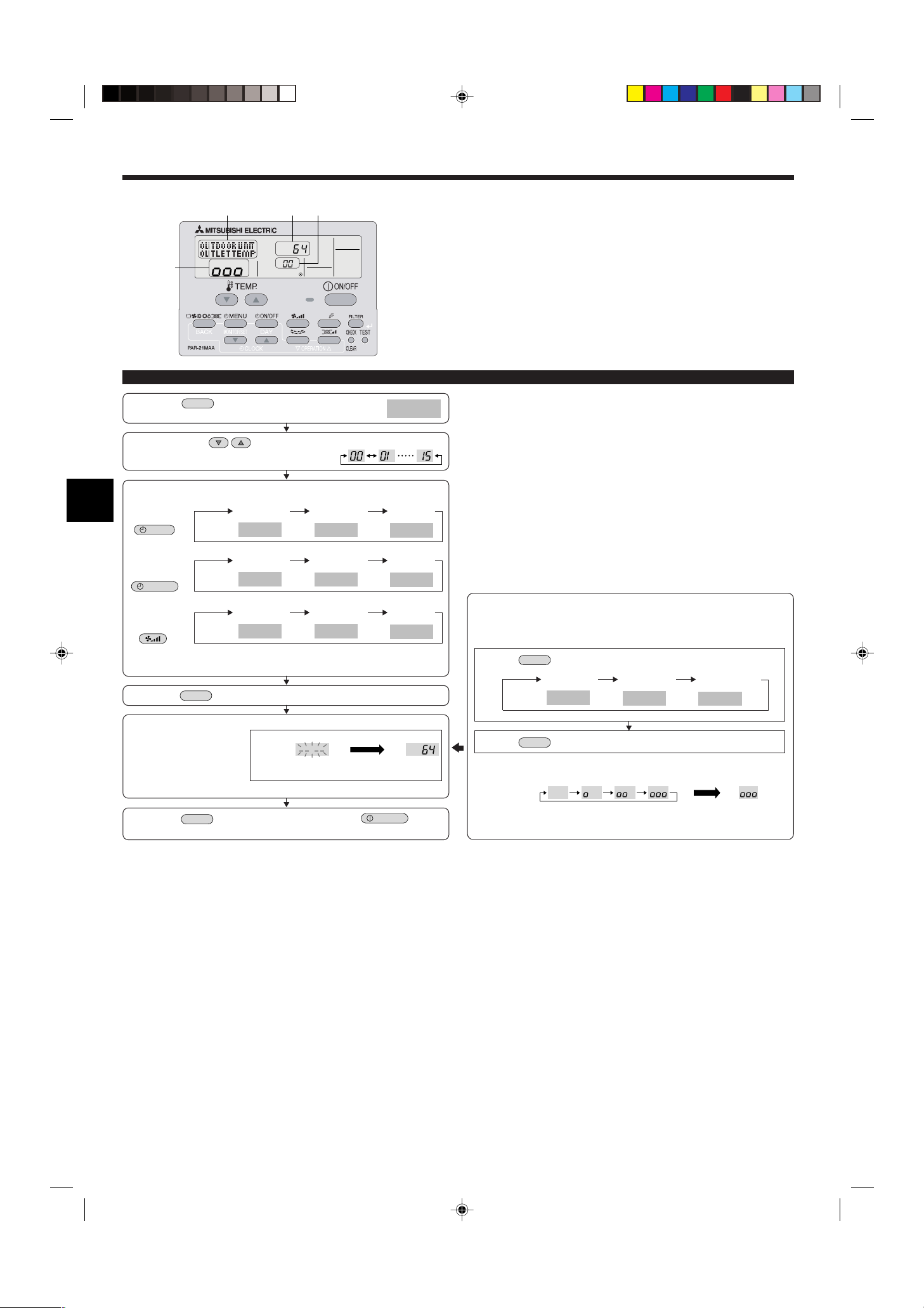
8. Easy maintenance function (Option)
D
A
C B
Display example (Comp discharge temperature 64°C)
Maintenance mode operation procedures
(1) Press the
activate the maintenance mode.
(2) Press the TEMP. buttons to set the refrigerant address.
(3) Select the data you want to display.
Compressor
information
Outdoor unit
information
button for three seconds to
Cumulative
operation time
Display A
Heat exchanger
temperature
Display A
Display A
Display B
ON/OFF
number
Comp discharge
temperature
Operation
current
Outdoor ambient
temperature
By using the maintenance mode, you can display many types of maintenance data
on the remote controller such as the heat exchanger temperature and compressor
current consumption for the indoor and outdoor units.
This function can be used whether the air conditioner is operating or not.
During air conditioner operation, data can be checked during either normal operation
or maintenance mode stable operation.
* This function cannot be used during the test run.
* The availability of this function depends on the connecting outdoor unit. Refer to the
brochures.
Indoor unit
information
Display A
Indoor room
temperature
Heat exchanger
temperature
Filter operation
time
* The filter operation time displayed is the number of hours the filter has been
used since the filter reset was performed.
(4) Press the
(5) The data is displayed in C.
button.
Display C
(Airflow temperature display example)
Flashing
Waiting for
response
Approx.
10 sec.
64°C
* Repeat steps (2) to (5) to check another date.
(6) Press the
button for three seconds or press the
button to
deactivate the maintenance mode.
Stable operation
Using the maintenance mode, the operation frequency can be fixed and the operation can be stabilized. If the air conditioner is stopped, use the following procedure to start this operation.
Press the
Display A
Press the
Waiting for stable
operation
Display D
button to select the operation mode.
Stable cooling
operation
Stable heating
operation
button.
Stable operation
cancellation
10-20 min.
Stable
operation
* You can check the data using steps (3) to (5) of the maintenance mode opera-
tion procedures while waiting for the stable operation.
14
Inhaltsverzeichnis
1. Sicherheitsvorkehrungen ....................................................................... 15
2. Aufstellort ............................................................................................... 16
3. Anbringung der Innenanlage ................................................................. 16
4. Installation der Kältemittelrohrleitung ..................................................... 18
1. Sicherheitsvorkehrungen
s Vor dem Einbau der Anlage vergewissern, daß Sie alle Informationen über
“Sicherheitsvorkehrungen” gelesen haben.
ss
s Vor dem Anschließen dieses Gerätes an das Stromnetz Ihr Stromversorgungs-
ss
unternehmen informieren oder dessen Genehmigung einholen.
Warnung:
Beschreibt Vorkehrungen, die beachtet werden müssen, um den Benutzer vor der
Gefahr von Verletzungen oder tödlichen Unfällen zu bewahren.
Vorsicht:
Beschreibt Vorkehrungen, die beachtet werden müssen, damit an der Anlage keine
Schäden entstehen.
Warnung:
• Bitten Sie Ihren Fachhändler oder einen geprüften Fachtechniker, die Installation
der Anlage vorzunehmen.
• Folgen Sie bei der Installation den Anweisungen in der Installationsanweisung,
und verwenden Sie Werkzeuge und Rohrleitungsbestandteile, die ausdrücklich zum
Einsatz desjenigen Kältemittels ausgelegt ist, das in der AussenanlagenInstallationsanleitung spezifiziert ist.
• Die Anlage muß entsprechend den Anweisungen installiert werden, um die Gefahr
von Schäden in Folge von Erdbeben, Stürmen oder starkem Windeinfluß zu minimieren. Eine falsch installierte Anlage kann herabfallen und dabei Verletzungen
oder Sachschäden verursachen.
• Die Anlage muß sicher an einem Bauteil installiert werden, das das Gewicht der
Anlage tragen kann.
• Wenn die Klimaanlage in einem kleinen Raum installiert wird, müssen Maßnahmen
ergriffen werden, damit die Kältemittelkonzentration auch bei Kältemittelaustritt
den Sicherheitsgrenzwert nicht überschreitet. Sollte Kältemittel austreten und der
Grenzwert der Kältemittelkonzentration überschritten werden, können durch den
Sauerstoffmangel im Raum Gefahren entstehen.
5. Verrohrung der Dränage ........................................................................ 19
6. Elektroarbeiten ....................................................................................... 20
7. Testlauf .................................................................................................. 24
8. Funktion für einfache Wartung (option) .................................................. 27
Erläutern Sie dem Kunden nach Abschluß der Installationsarbeiten die “Sicherheitsvorkehrungen” sowie die Nutzung und War tung der Anlage entsprechend den Informationen in der
Bedienungsanleitung und führen Sie einen Testlauf durch, um sicherzustellen, daß die Anlage ordnungsgemäß funktioniert. Geben Sie dem Benutzer sowohl die Installations- als
auch die Bedienungsanleitung zur Aufbewahrung. Diese Anleitungen sind auch den nachfolgenden Besitzern der Anlage weiterzugeben.
: Verweist auf einen Teil der Anlage, der geerdet werden muß.
Warnung:
Sorgfältig die auf der Hauptanlage aufgebrachten Aufschriften lesen.
• Lüften Sie den Raum, wenn bei Betrieb Kältemittel austritt. Wenn Kältemittel mit
einer Flamme in Berührung kommt, werden dabei giftige Gase freigesetzt.
• Alle Elektroarbeiten müssen entsprechend den örtlichen Vorschriften und den Anweisungen in dieser Anleitung von qualifizierten Fachelektrikern ausgeführt werden.
• Verwenden Sie zur Verdrahtung nur die angegebenen Kabel.
• Die Klemmleistenabdeckung der Anlage muss ordnungsgemäss angebracht sein.
• Verwenden Sie nur von Mitsubishi Electric zugelassenes Zubehör, und lassen Sie
dieses durch Ihren Fachhändler oder eine Vertragswerkstatt einbauen.
• Der Benutzer darf niemals versuchen, die Anlage zu reparieren oder an einem anderen Ort aufzustellen.
• Prüfen Sie die Anlage nach Abschluß der Installation auf Kältemittelaustritt. Wenn
Kältemittel in den Raum gelangt und mit der Flamme einer Heizung oder eines
Gasherds in Berührung kommt, werden dabei giftige Gase freigesetzt.
1.1. Vor der Installation (Umgebung)
Vorsicht:
• Setzen Sie die Anlage nicht in unüblichem Umfeld ein. Wenn die Klimaanlage in
Bereichen installiert ist, in denen sie Rauch, austretendem Öl (einschliesslich Maschinenöl) oder Schwefeldämpfen ausgesetzt ist, oder in Gegenden mit hohem
Salzgehalt, etwa am Meer, kann dies zu erheblichen Leistungsbeeinträchtigungen
und Schäden an den Geräteteilen im Inneren der Anlage zur Folge haben.
• Installieren Sie die Anlage nicht in Bereichen, in denen entzündliche Gase austreten, hergestellt werden, ausströmen oder sich ansammeln können. Wenn sich entzündliche Gase im Bereich der Anlage ansammeln, kann dies zu einem Brand oder
einer Explosion führen.
• Achten Sie darauf, daß sich weder Nahrungsmittel, Pflanzen, Käfigtiere, Kunstgegenstände noch Präzisionsinstrumente im direkten Luftstrom der Innenanlage oder
zu nahe der Anlage befinden, da diese durch Temperaturschwankungen oder tropfendes Wasser beschädigt werden können.
1.2. Vor Installation oder Transport
Vorsicht:
• Lassen Sie beim Transport der Anlagen besondere Vorsicht walten. Zum Transport
der Anlage sind mindestens zwei Personen nötig, da die Anlage 20 kg oder mehr
wiegt. Tragen Sie die Anlage nicht an den Verpackungsbändern. Tragen Sie Schutzhandschuhe, um Verletzungen der Hände durch die Kühlrippen oder andere Teile
zu vermeiden.
• Sorgen Sie für eine ordnungsgemäße Entsorgung der Verpackungsmaterialien.
Verpackungsmaterialien wie Nägel sowie andere metallene oder hölzerne Teile können Verletzungen verursachen.
• Um Kondenswasserbildung zu verhindern, muss die Kühlmittelleitung isoliert werden. Wenn die Kühlmittelleitung nicht korrekt isoliert ist, bildet sich Kondenswasser.
1.3. Vor den Elektroarbeiten
Vorsicht:
• Installieren Sie auf jeden Fall Leistungsschalter. Andernfalls besteht die Gefahr
von Stromschlägen.
• Verwenden Sie für die Netzleitungen handelsübliche Kabel mit ausreichender Kapazität.
Andernfalls besteht die Gefahr von Kurzschlüssen, Überhitzung oder eines Brandes.
• Achten Sie bei der Installation der Netzleitungen darauf, daß keine Zugspannung
für die Kabel entsteht.
• Wenn die Luftfeuchtigkeit im Raum 80% überschreitet oder wenn die Ablaßleitung
verstopft ist, kann Wasser von der Innenanlage tropfen. Installieren Sie die Innenanlage nicht an Stellen, an denen tropfendes Wasser Schäden verursachen kann.
• Bei der Installation der Anlage in Krankenhäusern oder Kommunikationseinrichtungen müssen Sie mit Lärmbelastung und elektronischen Störungen rechnen. Inverter, Haushaltsgeräte, medizinische Hochfrequenzapparate und
Telekommunikationseinrichtungen können Fehlfunktionen oder den Ausfall der
Klimaanlage verursachen. Die Klimaanlage kann auch medizinische Geräte in Mitleidenschaft ziehen, die medizinische Versorgung und Kommunikationseinrichtungen durch Beeinträchtigung der Bildschirmdarstellung stören.
• Bringen Sie Thermoisolierungen an den Rohren an, um Kondenswasserbildung zu
verhindern. Wenn die Abflußleitung nicht ordnungsgemäß installiert ist, können
Wasseraustritt und Beschädigungen von Decke, Fußboden, Möbeln oder anderen
Gegenständen die Folge sein.
• Die Klimaanlage darf nicht mit Wasser gereinigt werden. Dabei kann es zu Strom-
schlägen kommen.
• Alle Konusmuttern müssen mit einem Drehmomentschlüssel entsprechend der tech-
nischen Anweisungen angezogen werden. Wenn die Muttern zu fest angezogen
werden, besteht die Gefahr, dass sie nach einer gewissen Zeit brechen.
• Die Anlage muß geerdet werden. Wenn die Anlage nicht ordnungsgemäß geerdet
ist, besteht die Gefahr von Stromschlägen.
• Verwenden Sie Leistungsschalter (Erdschlußunterbrecher, Trennschalter (+B-Sicherung) und gußgekapselte Leistungsschalter) mit der angegebenen Kapazität.
Wenn die Leistungsschalterkapazität größer ist als vorgeschrieben, kann dies einen Ausfall der Klimaanlage oder einen Brand zur Folge haben.
1.4. Vor dem Testlauf
Vorsicht:
• Schalten Sie den Netzschalter mehr als 12 Stunden vor Betriebsbeginn ein. Ein
Betriebsbeginn unmittelbar nach Einschalten des Netzschalters kann zu schwerwiegenden Schäden der Innenteile führen.
• Prüfen Sie vor Betriebsbeginn, ob alle Platten, Sicherungen und weitere Schutzvorrichtungen ordnungsgemäß installiert sind. Rotierende, heiße oder unter Hochspannung stehende Bauteile können Verletzungen verursachen.
• Betreiben Sie die Klimaanlage nicht ohne eingesetzten Luftfilter. Wenn der Luftfilter nicht installiert ist, besteht die Gefahr, daß sich Schmutz ansammelt und die
Anlage dadurch ausfällt.
• Berühren Sie Schalter nicht mit nassen Händen. Dadurch besteht die Gefahr eines
Stromschlags.
• Berühren Sie die Kältemittelrohre während des Betriebs nicht mit bloßen Händen.
• Nach Beendigung des Betriebs müssen mindestens fünf Minuten verstreichen, ehe
der Hauptschalter ausgeschaltet wird. Andernfalls besteht die Gefahr von Wasseraustritt oder Ausfall der Anlage.
15
E
D
C
B
A
F
H
D
W
G H
2. Aufstellort
420
495
405
360
300
245
190
135
7532200352595
205
260
320
345
495
150
230
210
140
170
190
425
40
0
0
35
55
80
130
190
230
272
310
340
322
*
A
B
C
D
E
F
G
H
I
J
K
L
M
N
B
Y
Z
V
100
A
C
D
E
B
Fig. 2-1
3. Anbringung der Innenanlage
2.1. Außenabmessungen (Innenanlage) (Fig. 2-1)
Wählen Sie einen geeigneten Aufstellort mit nachstehenden Freiräumen für Aufstellung
und Wartung.
Modelle W D H AEFGH
35, 50 990 235 340 Min. 30 Max. 130 Min. 180 Min. 50 Min. 150
B Zimmerdecke
C Wand
D Möbel etc.
(mm)
Warnung:
Die Innenanlage an einer Decke montieren, die stark genug ist, um das Gewicht der
Anlage zu tragen.
2.2. Außenmaße (Außenanlage)
Siehe Aussenanlagen-Installationsanleitung.
1
2
3
3.1. Zubehörteile der Innenanlage prüfen (Fig. 3-1)
Zum Lieferumfang der Innenanlage gehört folgendes Sonderzubehör.
TEILENUMMER
1 Montagebrett 1
4
5
6
2 Blechschraube 4 × 35 12
ZUBEHÖR MENGE
FUND-/ANBRINGUNGSORT
Auf der Rückseite der Anlage anbringen
3 Rohrabdeckung 1
4 Band 3
5 Filzband 3
7
8
9
7 Halter der Fernbedienung 1
6 Drahtlose Fernbedienung 1
Im Inneren der
Anlage angebracht
8 Alkali-Batterien (Größe AAA) 2
9 Montagestück 1
0
Konusmutter
RP35, 50
P35, 50 0
2 (ø9,52, ø15,88)
0
Fig. 3-1
(mm)
3.2. Anbringung der Wandbefestigungen (Fig. 3-2)
3.2.1. Festlegung der Wandbefestigungen und Rohrleitungs-
positionen
s Mit den Wandbefestigungen die Einbauposition und die Position der zu bohren-
den Rohrleitungsöffnungen festlegen.
Warnung:
Bevor Sie ein Loch in die Wand bohren, müssen Sie den Bauherrn befragen.
A Stützteil J Rohrschlitz unten rechts (ø90)
B Montagebrett K Loch zum Ausbrechen für Rohrschlitz unten rechts
C Hauptkörper L
D Schlitz (6-11 × 20) M Lage des Aufweitungsanschlusses für Gasrohr
E Hauptanlage N Niveau-Einstellungsstandard
F Bohrung für Schraubbolzen (14-ø14) V Maßstab einsetzen
G Blechbohrung (49-ø5) Y Lochmitte
H Rohrschlitz unten links (ø90) Z Maßstab mit der Linie ausrichten
I Loch zum Ausbrechen für Rohrschlitz unten links
Lage des Aufweitungsanschlusses für Flüssigkeitsrohr
Fig. 3-2
3.2.2. Die Löcher für die Rohrleitung bohren (Fig. 3-3)
s Verwenden Sie einen Kernbohrer, um parallel zum Verlauf der Rohrleitung eine
Bohrung von 90 bis 100 mm im Durchmesser an der in der linken Abbildung ge-
zeigten Position zu erstellen.
s Der Wanddurchbruch sollte geneigt sein, so daß die Öffnung an der Außenseite
niedriger liegt als innen.
A Manschette
B Loch
C (Innenseite)
D Mauer
E (Außenseite)
s Eine Innenauskleidung (mit einem Durchmesser von 90 mm und vor Ort zu be-
schaffen) in die Öffnung einsetzen.
Hinweis:
Der Wanddurchbruch muß schräg angebracht sein, damit ein guter Abfluß gewähr-
leistet ist.
Fig. 3-3
16
3. Anbringung der Innenanlage
1
D
2
B
A
C
A
B
D
C
a
A
b
a
a
A
B
b
b
A
B
C
B
A
A
30~40
C
A
B
Fig. 3-4
Fig. 3-5
A Min. 140 mm
B Min. 300 mm
C Min. 55 mm
D Montagebrett
3.2.3. Anbringung der Wandbefestigungen
s Da die Innenanlage fast 30 kg wiegt, muß der Aufstellungsort sorgfältig ausge-
sucht werden. Wenn die Wand nicht stark genug erscheint, diese vor dem Anbringen der Anlage mit Brettern oder Balken verstärken.
s Die Wandbefestigung muß, wenn möglich, an beiden Enden und in der Mitte gesi-
chert sein. Niemals an einer einzigen Stelle oder in asymmetrischer Form befestigen.
(Wenn möglich, die Befestigung an allen durch einen fettgedruckten Pfeil markierten Stellen sichern.) (Fig. 3-4)
Warnung:
Wenn möglich, die Befestigung an allen Stellen, die mit einem fettgedruckten Pfeil
markiert sind, sichern.
Vorsicht:
• Der Gerätekörper muß waagerecht montiert werden.
• An den mit ▲ markierten Löchern befestigen.
1 Das Loch mit einem Gewinde versehen.
2 Die Horizontale kann leicht ermittelt werden, wenn man ein Gewicht an eine Schnur hängt
und diese an der Markierung ausrichtet.
3.3. Beim Einbetten der Rohre in die Wand (Fig. 3-5)
• Befinden sich die Rohre unten links.
• Wenn die internen/externen Anschlußleitungen der Kühl- und Ablaßrohre vorab in die
Wand eingebettet werden müssen, müssen die überstehenden Rohre möglicherweise
gebogen und deren Längen an die Gegebenheiten der Anlage angepaßt werden.
• Beim Anpassen der Länge der eingebetteten Kühlrohrleitung die Markierung auf der
Montageplatte als Bezug nutzen.
• Beim Bau für die Länge der überstehenden Rohre etwas Spielraum vorsehen.
A Montageplatte
B Bezugsmarkierung für Aufweitungsanschluß
C Durchbruch
D Rohrleitung vor Ort
Fig. 3-6
Fig. 3-7
3.4. Vorbereitung der Innenanlage
Hintere, rechte und untere Rohrleitung (Fig. 3-6)
1. Kühl- und Ablaßrohr zusammenbinden.
• Die Rohre mit Kunststoffband an drei oder mehr Stellen zusammenbinden. Dadurch wird
die Durchführung der Rohre durch die Wand erleichtert.
2. Den Eckkasten abnehmen und bei Bedarf die Rohrschlitze ausbrechen.
• Zum Abnehmen des Eckkastens diesen in Richtung nach unten drücken b; dabei muß
gleichzeitig das obere Seitenteil des Eckkastens a hinein gedrückt werden.
A Eckkasten
B Unterabdeckung
Rohrleitung links und links hinten (Fig. 3-7)
1. Die untere Abdeckung abnehmen
• Die untere Abdeckung durch Schieben zur Rückseite der Anlage b abnehmen und dabei
gleichzeitig die beiden durch Pfeilköpfe a gekennzeichneten Punkte drücken.
2. Den Eckkasten abnehmen und bei Bedarf die beiden Löcher zum Ausbrechen heraus-
brechen.
3.5. Montage der Innenanlage
1. Montageplatte an der Wand befestigen.
2. Die Innenanlage an die beiden Haken, die sich im oberen Teil der Montageplatte befin-
den, aufhängen.
Hintere, rechte und untere Rohrleitung (Fig. 3-8)
3. Die Innenanlage anbringen.
4. Nach Anschluß der Rohre den Eckkasten wieder an der ursprünglichen Stelle anbrin-
gen (den Abbauvorgang in umgekehrter Reihenfolge vornehmen).
A Quadratisches Loch
B Haken
Fig. 3-8
Rohrleitung links und links hinten (Fig. 3-9)
(mm)
Fig. 3-9
3. Aus dem Packmaterial ein Stück zum Befestigen (Montagestück) ausschneiden.
4. Ziehen Sie die Innenanlage wie in der Abbildung unten dargestellt in Richtung auf Ihren
Körper. Schieben Sie dann das Montagestück unter Verwendung der Einstellungs-
markierungen des Montagestücks als Bezugspunkt in Richtung auf die Montageplatte
hinein.
5. Nach Anschluß der Rohr- und Elektroleitungen die Unterabdeckung an den ursprüngli-
chen Platz zurücksetzen und das Montagestück abnehmen. Dann die Innenanlage, wie
in der Abbildung links dargestellt, befestigen.
6. Den Eckkasten an den ursprünglichen Platz zurücksetzen.
A Montagestück
B Zimmerdecke
C Rippe
17
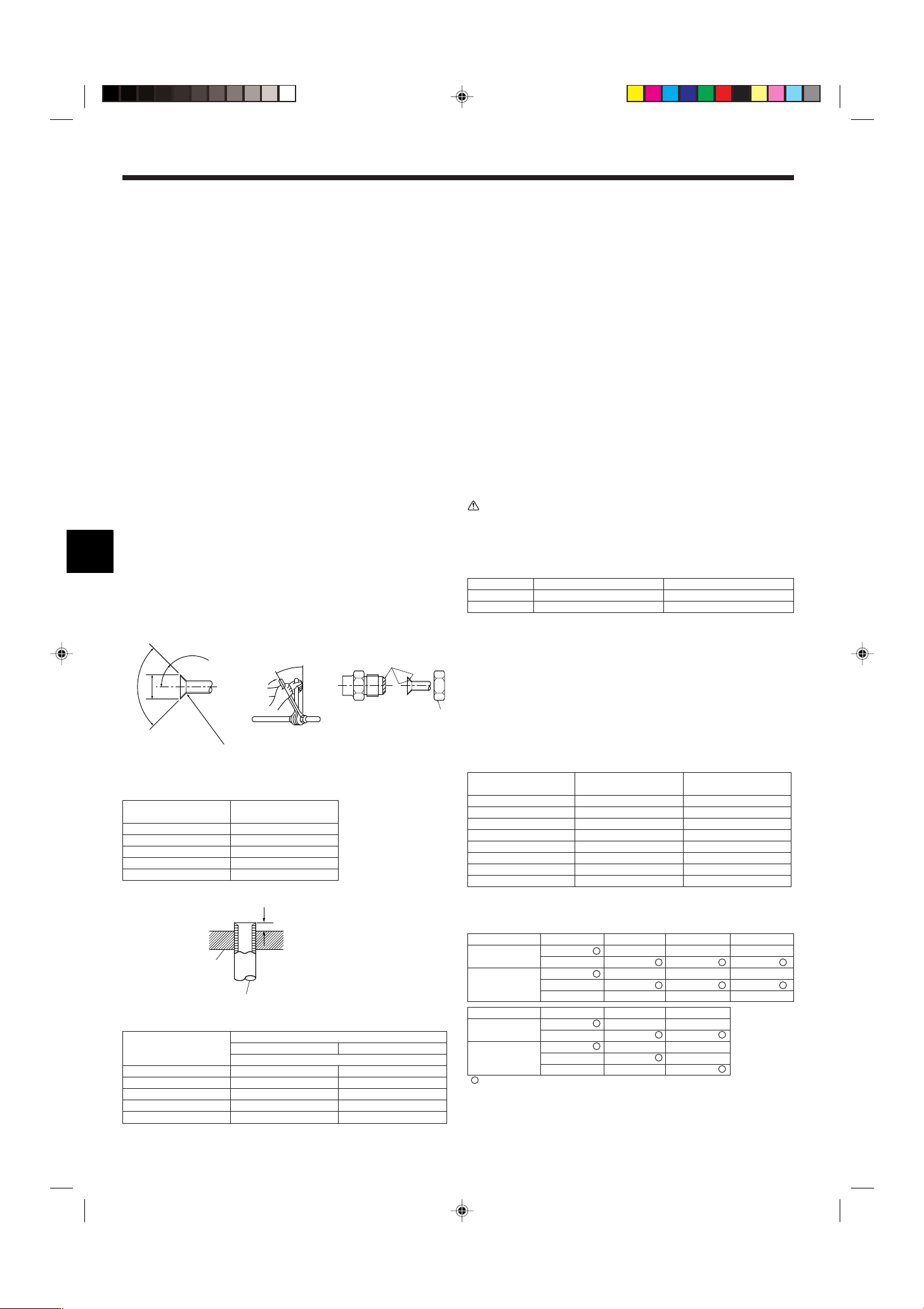
4. Installation der Kältemittelrohrleitung
90° ±0,5°
øA
R0,4~R0,8
A
45°±2°
B
C
D
A
A
B
4.1. Sicherheitsvorkehrungen
4.1.1. Für Geräte, die das Kältemittel R407C verwenden
• Kältemittel und Öl.
• Keine zerquetschten, verformten oder verfärbten Leitungen verwenden. Das Inne-
re der Leitung soll sauber und frei von schädlichen Schwefelsubstanzen,
Oxidationsmitteln, Schmutz, Staub oder Feuchtigkeit sein.
• Die bei der Installation verwendete Rohrleitung in einem geschlossenen Raum aufbewahren und beide Enden bis unmittelbar vor dem Hartlöten geschlossen halten.
• Zum Beschichten der Konus- und Flanschanschlüsse Esteröl/Ätheröl oder Alkyl-
benzol (kleine Menge) als Kältemaschinenöl verwenden.
• Zur Füllung des Systems flüssiges Kältemittel verwenden.
• Kein anderes Kältemittel als R407C verwenden.
• Eine Vakuumpumpe mit einem Reverse Flow (Gegenstrom)-Rückschlagventil ver-
wenden.
• Vorrichtungen, die bei herkömmlichen Kältemitteln verwendet werden, nicht ein-
setzen.
• Keinen Füllzylinder verwenden.
• Beim Einsatz der Handhabungsvorrichtungen besondere Sorgfalt walten lassen.
• Nicht handelsübliche Trockner verwenden.
4.1.2. Für Geräte, die das Kältemittel R410A verwenden
• Tragen Sie eine kleine Menge Esteröl/Ätheröl oder Alkylbenzol als Kältemittelöl auf
die Konusanschlüsse auf.
• Verwenden Sie zur Verbindung der Kältemittelrohrleitungen für nahtlose Rohre aus
Kupfer und Kupferlegierungen Kupferphosphor C1220. Verwenden Sie Kältemittel-
rohre mit Stärken wie in der folgenden Tabelle angegeben. Vergewissern Sie sich,
daß die Rohre von innen sauber sind und keine schädlichen Verunreinigung wie
Schwefelverbindungen, Oxidationsmittel, Fremdkörper oder Staub enthalten.
Warnung:
Verwenden Sie bei der Installation oder nach einem Transport der Klimaanlage zum
Füllen der Kältemittelleitungen ausschließlich das angegebene Kältemittel (R410A).
Mischen Sie es nicht mit anderen Kältemitteln, und achten Sie darauf, daß keine Luft
in den Leitungen verbleibt. Durch Luft in den Leitungen können Druckspitzen verursacht werden, die zu Rissen und Brüchen sowie anderen Schäden führen können.
Fig. 4-1
A Abmessungen der Aufweitungsschnitte
Kupferrohr O.D. Aufweitungsabmessungen
(mm)
ø6,35 8,7 - 9,1
ø9,52 12,8 - 13,2
ø12,7 16,2 - 16,6
ø15,88 19,3 - 19,7
ø19,05 23,6 - 24,0
øA Abmessungen (mm)
Fig. 4-2
Kupferrohr O.D.
(mm)
ø6,35 0 - 0,5 1,0 - 1,5
ø9,52 0 - 0,5 1,0 - 1,5
ø12,7 0 - 0,5 1,0 - 1,5
ø15,88 0 - 0,5 1,0 - 1,5
ø19,05 0 - 0,5 1,0 - 1,5
Aufweitungswerkzeug für R22·R407C
A Schneidwerkzeug
B Kupferrohr
A (mm)
Aufweitungswerkzeug für R410A
Kupplungsbauweise
Flüssigkeitsrohr ø6,35 Stärke 0,8 mm ø9,52 Stärke 0,8 mm
Gasrohr ø12,7 Stärke 0,8 mm ø15,88 Stärke 1,0 mm
• Verwenden Sie keine dünneren Rohre als oben angegeben.
RP35, 50 RP60-140
4.2. Rohranschlüsse (Fig. 4-1)
• Wenn im Handel erhältliche Kupferrohre verwendet werden, Flüssigkeits- und Gasrohre
mit im Handel erhältlichem Isoliermaterial (Hitzebeständig bis 100 °C und mehr, Stärke
12 mm oder mehr) umwickeln.
• Die in der Anlage befindlichen Teile der Ablaßrohre sollten mit Isoliermaterial aus Schaum-
stoff (spezifisches Gewicht 0,03 - 9 mm oder stärker) umwickelt werden.
• Vor dem Anziehen der Konusmutter eine dünne Schicht Kältemittel-Öl auf das Rohr und
auf die Oberfläche des Sitzes an der Nahtstelle auftragen.
• Mit zwei Schraubenschlüsseln die Rohrleitungsanschlüsse fest anziehen.
• Die Anschlüsse der Innenanlage mit dem mitgelieferten Isolier material für die Kältemittel-
rohrleitung isolieren. Beim Isolieren sorgfältig vorgehen.
B Anzugsdrehmoment für die Konusmutter
Kupferrohr O.D. Konusmutter O.D. Anzugsdrehmoment
(mm) (mm) (N·m)
ø6,35 17 14 - 18
ø6,35 22 34 - 42
ø9,52 22 34 - 42
ø12,7 26 49 - 61
ø12,7 29 68 - 82
ø15,88 29 68 - 82
ø15,88 36 100 - 120
ø19,05 36 100 - 120
C Tragen Sie Kältemaschinenöl auf die gesamte Konusauflagefläche auf.
D Die richtigen Konusmuttern, die zur Rohrgröße der Außenanlage passen, verwenden.
Verfügbare Rohrgröße
RP35, 50 RP60 RP71
Flüssigkeitsseite
Gasseite ø15,88 ø15,88
Flüssigkeitsseite
Gasseite –ø15,88
: Werksseitiger Konusmutteraufsatz für den Wärmetauscher
ø6,35
ø9,52 ø9,52
ø12,7 –– –
–––ø19,05
P25
ø6,35
–ø9,52
ø12,7 ––
––ø19,05
ø6,35 ––
P35, 50, 60, 71
P100, 125, 140
––
ø9,52 ø9,52
ø15,88 ø15,88
ø9,52
–
RP100, 125, 140
18
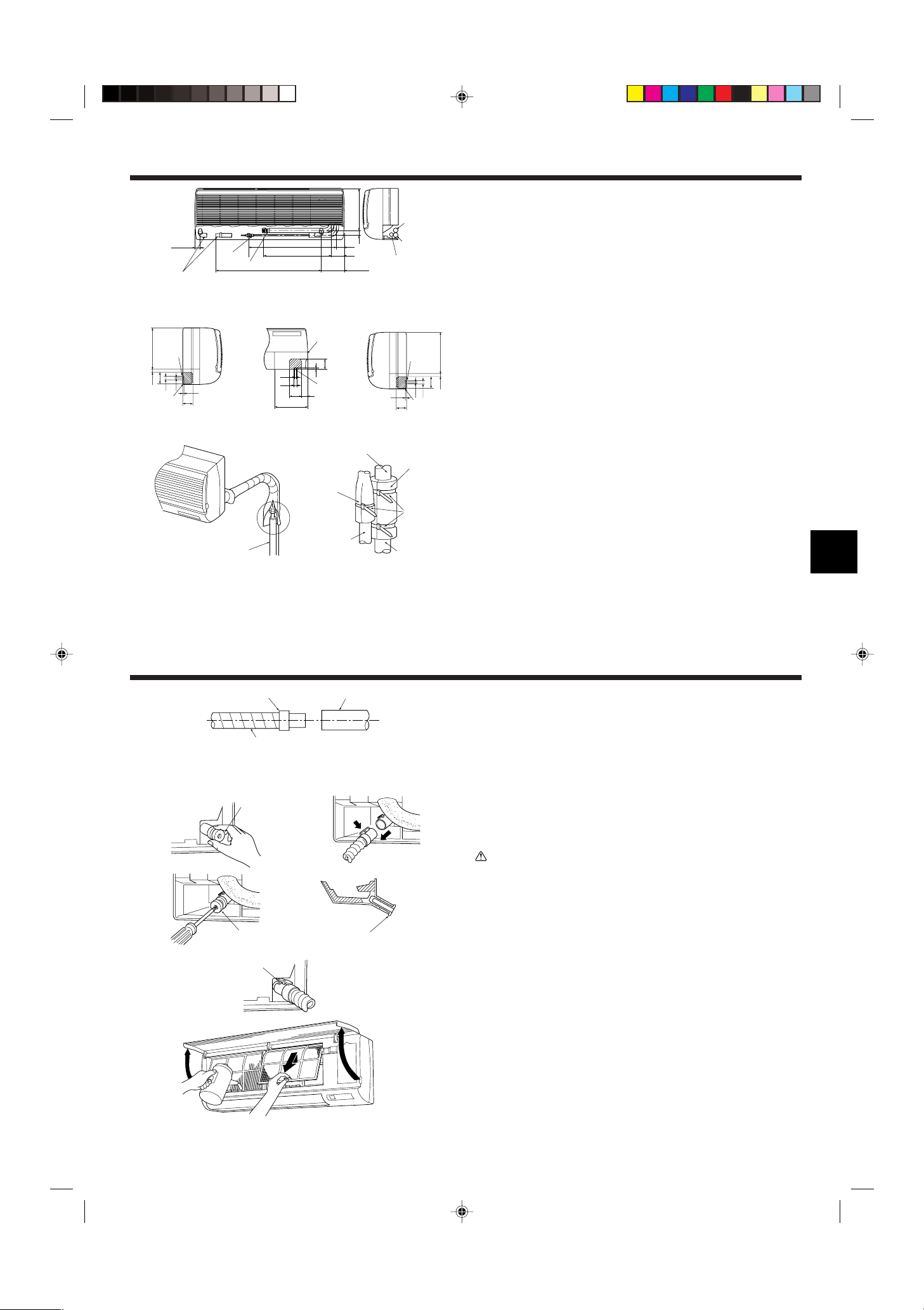
4. Installation der Kältemittelrohrleitung
A
B
C
D
E
F
G
E
D
B
C
A
C
B
D
F
35
449
581
28031
54
86
153
700
A
E
60
10
22
70
21
245
D
8
B
E
D
10
190
22
70 35
8
60
C
E
8
60
10
22
70
21 245
D
A
B
C
A
a
b
A
A
B
1
Fig. 4-3
2
4.3. Anordnung der Kältemittel- und Ablaßrohrleitungen
1 Anordnung der Kältemittel- und Ablaßrohrleitungen (Fig. 4-3)
• Das Ablaßrohr kann zur Anpassung an die Gegebenheiten vor Ort in der Mitte getrennt
werden.
A (Gesamtlänge des flexiblen Schlauchs) D Auslaufschlauch
B Flüssigkeitsrohrleitung E Rohrleitung an der linken Seite
C Gasrohrleitung F Rohrleitung an der rechten Seite
2 Die Lage der auszubrechenden Löcher auf dem Gerätekörper festlegen. (Fig. 4-4)
s Brechen Sie die Löcher mit einem Sägeblatt oder einem geeigneten Messer aus.
Darauf achten, keine anderen Teile der Anlage zu beschädigen.
• Den Eckkasten abnehmen und mit dem Bohrer ein Loch ausbrechen. Wenn ein Loch
angebracht wird, ohne den Kasten abzunehmen, kann der Ablaßschlauch beschädigt
werden.
A Rohrleitung an der linken Seite D Kabeldurchgang für Fernbedienung
B Untere Rohrleitung E Eckkasten
C Rohrleitung an der rechten Seite
Fig. 4-4
4.4. Rohrleitungen für Kältemittel (Fig. 4-5)
Innenanlage
1. Die Konusmutter und den Deckel der Innenanlage abnehmen.
2. Flüssigkeits- und Gasrohr am Ende aufweiten und Kältemaschinenöl (beim Fachhänd-
ler vor Ort zu beschaffen) auf die Oberfläche des aufgeweiteten Blechs auftragen.
3. Die Kühlleitung des Hausanschlusses schnell an die Anlage anschließen.
4. Die Rohrleitungsabdeckung 3, die am Gasrohr angebracht ist, herumwickeln und dar-
auf achten, daß die Anschlußstelle nicht sichtbar ist.
5. Die Rohrleitungsabdeckung der Flüssigkeitsrohrleitung der Anlage herumwickeln und
sicherstellen, daß sie das Isoliermaterial der Flüssigkeitsrohrleitung des Hausanschlusses
abdeckt.
Fig. 4-5
6. Die mitgelieferten Bänder 4 zur Abdichtung beider Enden (15–20 mm) jeder Rohrab-
deckung 3 verwenden.
A Kühlrohr und Isolierung (beim örtlichen Fachhändler erhältlich)
B Gasrohrleitung der Anlage E Bänder 4
C Flüssigkeitsrohrleitung der Anlage F Gasrohrleitung des Hausanschlusses
D Rohrabdeckung 3 G Flüssigkeitsrohrleitung des Hausanschlusses
5. Verrohrung der Dränage
Fig. 5-1
1
3
4
Fig. 5-2
2
5.1. Verrohrung der Dränage (Fig. 5-1)
• Ablaßrohre sollten eine Neigung von 1/100 oder mehr aufweisen.
• Zur Verlängerung der Auslauf-/Dränagerohrleitung einen im Handel erhältlichen biegsa-
men Schlauch (Innendurchmesser 15 mm) oder ein Rohr aus Hartvinylchlorid (VP-20/
O.D. ø26 PVC Rohr) verwenden. Darauf achten, daß an den Anschlußstellen kein Was-
ser austritt.
• Wenn die Auslauf-/Dränagerohrleitung durch die Innenanlage geführt wird, muß sie mit
einem handedsüblichen Isoliermaterial (Schaumpolyäthylen mit einem spezifischen Gewicht von 0,03 und einer Stärke von 9 mm oder mehr) abgedeckt werden.
• Ablaßrohrleitung nicht direkt in einen Drängraben, in dem sich Schwefeldämpfe bilden
können, münden lassen.
• Nach Abschluß der Rohrverlegung vergewissern, daß Wasser aus dem Ende des Ablaß-
rohres herausfließt.
A Ablaßanschlußmuffe C Ablaßschlauch der Innenanlage
B Ablaßleitung des Hausanschlusses (VP-20)
Vorsicht:
Das Ablaßrohr sollte gemäß Angaben im Installationshandbuch eingebaut werden,
um einwandfreie Dränage zu gewährleisten. Thermoisolierung der Ablaßrohre ist notwendig, um Bildung von Kondenswasser zu verhindern. Wenn die Ablaßrohre nicht
vorschriftsmäßig installiert und isoliert wurden, kann Kondenswasser auf die Zimmerdecke, den Boden oder sonstiges Inventar tropfen.
Vorbereitung der Rohrleitung links und links hinten (Fig. 5-2)
1 Den Ablaßdeckel abnehmen
• Den Ablaßdeckel abnehmen, indem das am Ende des Rohres herausstehende Teil erfaßt
und herausgezogen wird.
A Ablaßdeckel
2 Den Ablaßschlauch abnehmen
• Den Ablaßschlauch abnehmen, indem man den Boden des Schlauchs a (durch Pfeil
gekennzeichnet) erfaßt und zu sich hin zieht b.
3 Den Ablaßdeckel einsetzen
• Einen Schraubenzieher in das Loch am Ende des Rohres einführen und darauf achten, in
Richtung des Bodens des Ablaßdeckels zu drücken.
4 Den Ablaßschlauch einführen
• Den Ablaßschlauch schieben bis er sich am Boden des Anschlußausgangs des Ablaß-
kastens befindet.
• Bitte dafür sorgen, daß der Haken des Ablaßschlauchs sachgerecht über dem über-
stehenden Anschlußausgang des Ablaßkastens angebracht ist.
B Haken
Die Seitenplatte der Innenanlage auf der Ablaßseite abnehmen. Wasser in die Dränpfanne
gießen und vergewissern, daß es am Ende des Ablaßrohres herausfließt. Wenn dies der
Fall ist, Seitenblech wieder anbringen.
19
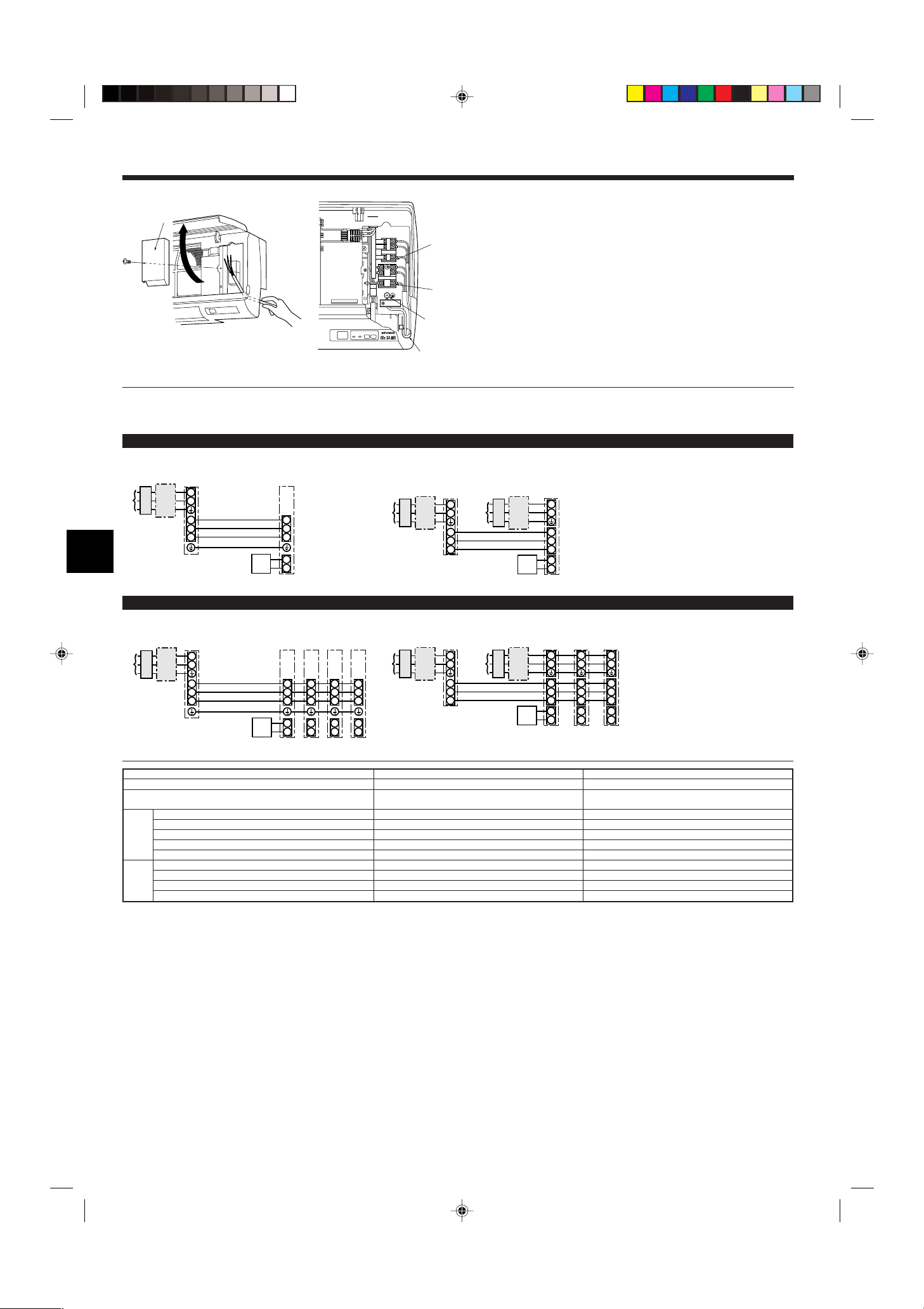
6. Elektroarbeiten
B
C
D
E
NL
S2 S3S1
A
S1
S2
L
N
1
2
S1
S2
S3
S3
AB C
D
E
F
G
S1
S2
L
N
1
2
S1
S2
S3
1
2
S1
S2
S3
S3
1
2
S1
S2
S3
1
2
S1
S2
S3
ABC
D
E
F
GGGG
S1
S2
L
N
1
2
L
N
S1
S2
S3
S3
ABC
DG
H
E
F
BC
S1
S2
L
N
1
2
L
N
S1
S2
S3
1
2
L
N
S1
S2
S3
1
2
L
N
S1
S2
S3
S3
ABC
D
E
C
GGG
BH
F
Fig. 6-1
6.1.1. Die Stromversorgung der Innenanlage von der Außenanlage
Es sind folgende Anschlussmuster verfügbar.
Die Stromversorgung der Außenanlagen erfolgt je nach Modell unterschiedlich.
1:1-System
<Für Modelle ohne Heizung>
<Für Modelle mit Heizung>
6.1. Innenanlage (Fig. 6-1)
1. Den Eckkasten abnehmen.
2. Jede Elektroleitung in die Anlage installieren.
3. Das Frontgitter öffnen, eine Blechschraube abnehmen und die Abdeckung der Klemm-
leiste entfernen.
A Abdeckung der Klemmleiste
4. Jede Elektroleitung sachgerecht an der Klemmleiste befestigen.
• Für zukünftige Wartungs- und Bedienungsarbeiten die Elektroleitung mit genügend zu-
sätzlicher Länge (Spiel) vorsehen.
5. Alle abgenommenen Teile wieder dort anbringen wo sie vorher waren.
6. Mit einer Klemme aus dem unteren Bereich des Elektrokastens jede einzelne Elektroleitung befestigen.
B Klemmleiste für die Verbindung zwischen Innen-/Außenanlage
C Klemmleiste für die Heizung (Modelle PKH)
D Erdungspunkt
E Klemme
A Netzanschluss der Außenanlage
B Erdschlussunterbrecher
C Unterbrecher oder Trennschalter
D Außenanlage
E Verbindungskabel Innenanlage/Außenanlage
F Fernbedienung
G Innenanlage
H Netzanschluss für Heizung
*Für die Innen- und Außenanlagen neben jedem Schaltplan einen Aufkleber A, der sich bei den Bedienungsanleitungen befindet, anbringen.
System mit gleichzeitig laufenden Doppel-/Dreifach-/Vierfach-Anlagen
<Für Modelle ohne Heizung>
<Für Modelle mit Heizung>
*Für die Innen- und Außenanlagen neben jedem Schaltplan einen Aufkleber A, der sich bei den Bedienungsanleitungen befindet, anbringen.
Innenanlage Modell
Stromversorgung der Innenanlage (Heizung)
Eingangskapazität der Innenanlage (Heizung)
Hauptschalter (Unterbrecher)
Stromversorgung der Innenanlage (Heizung)
)
2
Erdungsleitung des Netzanschlusses der Innenanlage (Heizung)
*1
Innenanlage-Außenanlage *2
Erdungsleitung der Innen-/Außenanlage *2
× Stärke (mm
Verdrahtung
Fernbedienung-Innenanlage *3
Zahl der Leitungen
Innenanlage (Heizung) L-N *4
Innenanlage-Außenanlage S1-S2 *4
des
Innenanlage-Außenanlage S2-S3 *4
Stromkreises
Fernbedienung-Innenanlage *4
Nennspannung
*1. An jedem der einzelnen Pole einen nichtschmelzbaren Trennschalter (NF) oder einen Erdschlussunterbrecher (NV) mit einem Kontaktabstand von mindestens 3 mm einsetzen.
*2. <Für 25-140 Außenanlagen>
PKA PKH
– ~/N (Eine), 50 Hz, 230 V
– 16 A
– 2 × Min. 1,5
– 1 × Min. 1,5
3 × 1,5 (Polar) 3 × 1,5 (Polar)
1 × Min.1,5 –
––
– AC 230 V
AC 230 V AC 230 V
DC 24 V DC 24 V
DC 12 V DC 12 V
Max. 45 m
Wenn 2,5 mm2 verwendet werden, max. 50 m
Wenn 2,5 mm2 verwendet werden und S3 getrennt ist, max. 80 m
Für PUHZ-RP100/125/140 YHA-Anwendungen abgeschirmte Elektroleitungen verwenden. Der abgeschirmte Teil muss an der Innenanlage ODER der Außenanlage geerdet werden, NICHT an beiden.
<Für 200/250 Außenanlagen>
Max. 18 m
Wenn 2,5 mm2 verwendet werden, max. 30 m
Wenn 4 mm2 verwendet werden und S3 getrennt ist, max. 50 m
Wenn 6 mm2 verwendet werden und S3 getrennt ist, max. 80 m
*3. Das Fernbedienungszubehör ist mit einer Elektroleitung von 10 m ausgestattet. Max. 500 m
*4. Die Angaben gelten NICHT immer gegenüber der Erdleitung.
Klemme S3 hat 24 V Gleichstrom gegenüber Klemme S2. Zwischen den Klemmen S3 und S1 gibt es keine elektrische Isolierung durch den Transformator oder eine andere elektrische Vorrichtung.
Hinweise: 1. Die Größe der Elektroleitung muß den jeweiligen örtlichen und nationalen gesetzlichen Vorschriften entsprechen.
2. Als Kabel für die Stromversorgung und die Verbindung von Innen- und Außenanlage muß mindestens ein polychloropren-beschichtetes, flexibles Kabel
(entsprechend 245 IEC 57) gewählt werden.
3. Eine Erdleitung, die länger als andere Kabel ist, installieren.
A Netzanschluss der Außenanlage
B Erdschlussunterbrecher
C Unterbrecher oder Trennschalter
D Außenanlage
E Verbindungskabel Innenanlage/Außenanlage
F Fernbedienung
G Innenanlage
H Netzanschluss für Heizung
20
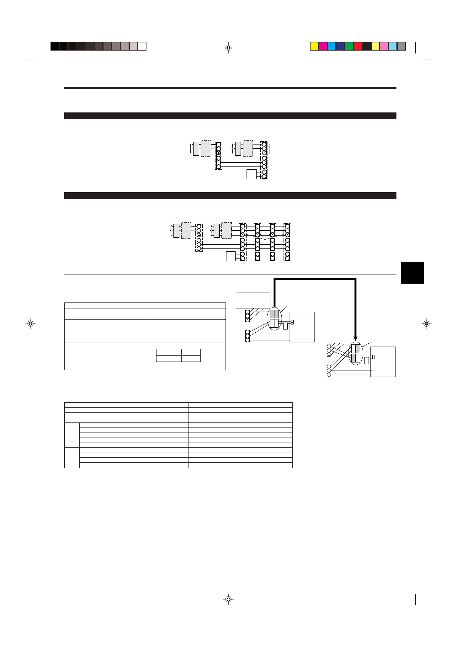
6. Elektroarbeiten
S1
S2
L
N
1
2
L
N
S1
S2
S3
S3
A
CB
D
JEB
C
F
G
H
S1
S2
L
N
1
2
L
N
S1
S2
S3
1
2
L
N
S1
S2
S3
1
2
L
N
S1
S2
S3
1
2
L
N
S1
S2
S3
S3
ABC
D
E
JBC
F
H
GGGG
ON
OFF 1 2
(SW8)
3
S1
S2
S3
L
N
BLUE
BLUE
YELLOW
YELLOW
CND
CND
ORANGE
CND
ORANGE
S1
S2
S3
L
N
YELLOW
BLUE
BLUE
YELLOW
CND
6.1.2. Die Netzanschlüsse für Innenanlage/Außenanlage voneinander trennen (Nur für Anwendungen von PUHZ)
Es sind folgende Anschlussmuster verfügbar.
Die Stromversorgung der Außenanlagen erfolgt je nach Modell unterschiedlich.
1:1 System
<Für Modelle ohne Heizung>
* Der wahlweise erhältliche Ersatzteilbausatz für Elektroleitungen ist erforderlich.
*Für die Innen- und Außenanlagen neben jedem Schaltplan einen Aufkleber B, der sich bei den Bedienungsanleitungen befindet, anbringen.
System mit gleichzeitig laufenden Doppel-/Dreifach-/Vierfach-Anlagen
<Für Modelle ohne Heizung>
* Der wahlweise erhältliche Ersatzteilbausatz für Elektroleitungen ist erforderlich.
A Netzanschluss der Außenanlage
B Erdschlussunterbrecher
C Unterbrecher oder Trennschalter
D Außenanlage
E Verbindungskabel Innenanlage/Außenanlage
F Fernbedienung
G Innenanlage
H wahlweise erhältlich
J Netzanschluss der Innenanlage
A Netzanschluss der Außenanlage
B Erdschlussunterbrecher
C Unterbrecher oder Trennschalter
D Außenanlage
E Verbindungskabel Innenanlage/Außenanlage
F Fernbedienung
G Innenanlage
H wahlweise erhältlich
J Netzanschluss der Innenanlage
*Für die Innen- und Außenanlagen neben jedem Schaltplan einen Aufkleber B, der sich bei den Bedienungsanleitungen befindet, anbringen.
Wenn die Innen- und Außenanlagen getrennte Netzanschlüsse haben, nachstehende Tabelle beachten. Bei Verwendung des wahlweise erhältlichen Ersatzteilbausatzes für die
Elektroleitungen die Verdrahtung des Schaltkastens der Innenanlage gemäß der Abbildung
rechts sowie der DIP-Schalter-Einstellungen der Schalttafel der Außenanlage ändern.
Technische Daten der Innenanlage
Klemmleistenbausatz für den Netzanschluss
der Innenanlage (wahlweise erhältlich)
Änderung des Anschlusses des Steckers für
den Schaltkasten der Innenanlage
Neben jedem Schaltplan für die Innen- und
Außenanlagen angebrachter Aufkleber
Erforderlich
Erforderlich
Erforderlich
Einstellungen für DIP-Schalter der Außenanlage (nur bei Verwendung von getrennten
Netzanschlüssen für Innen-/Außenanlagen)
Elektroheizung
(Für Modelle mit
Heizung)
Stromversorgung der Innenanlage erfolgt von der
Außenanlage (bei Versand ab Werk)
Stecker (bei Versand ab Werk sind die
Anschlüsse für die Stromversorgung der
Innenanlage von der Außenanlage
ausgelegt)
Schalttafel der
Innenanlage
Elektroheizung
(Für Modelle mit
Heizung)
Wenn Innen- und
Außenanlagen
getrennte
Netzanschlüsse
haben, die
Anschlüsse der
Stecker, wie in der
nachstehenden
Abbildung
dargestellt, ändern.
Stecker
Schalttafel der
Innenanlage
* Es gibt drei Arten von Aufklebern (Aufkleber A, B und C) Je nach Verdrahtungsverfahren
die jeweils richtigen Aufkleber an den Anlagen anbringen.
Getrennte Netzanschlüsse für Innenanlage/
Außenanlage
Innenanlage Modell
Stromversorgung der Innenanlage
Eingangskapazität der Innenanlage
Hauptschalter (Unterbrecher)
Stromversorgung der Innenanlage
)
2
Erdungsleitung des Netzanschlusses der Innenanlage
Innenanlage-Außenanlage *2
Erdungsleitung der Innen-/Außenanlage
× Stärke (mm
Verdrahtung
Fernbedienung-Innenanlage *3
Zahl der Leitungen
Innenanlage L-N *4
Innenanlage-Außenanlage S1-S2 *4
des
Innenanlage-Außenanlage S2-S3 *4
Stromkreises
Fernbedienung-Innenanlage *4
Nennspannung
*1
PKA
~/N (Eine), 50 Hz, 230 V
16 A
2 × Min. 1,5
1 × Min. 1,5
2 × Min. 0,3
–
–
AC 230 V
–
DC 24 V
DC 12 V
*1. An jedem der einzelnen Pole einen nichtschmelzbaren Trennschalter (NF) oder einen Erdschlussunterbrecher (NV) mit einem Kontaktabstand von mindestens 3 mm einsetzen.
*2. Max. 120 m
Für PUHZ-RP100/125/140 YHA-Anwendungen abgeschirmte Elektroleitungen verwenden. Der abgeschirmte Teil muss an der Innenanlage ODER der Außenanlage geerdet werden, NICHT an
beiden.
*3. Das Fernbedienungszubehör ist mit einer Elektroleitung von 10 m ausgestattet. Max. 500 m
*4. Die Angaben gelten NICHT immer gegenüber der Erdleitung.
Hinweise: 1. Die Größe der Elektroleitung muß den jeweiligen örtlichen und nationalen gesetzlichen Vorschriften entsprechen.
2. Als Kabel für die Stromversorgung und die Verbindung von Innen- und Außenanlage muß mindestens ein polychloropren-beschichtetes, flexibles Kabel
(entsprechend 245 IEC 57) gewählt werden.
3. Eine Erdleitung, die länger als andere Kabel ist, installieren.
21
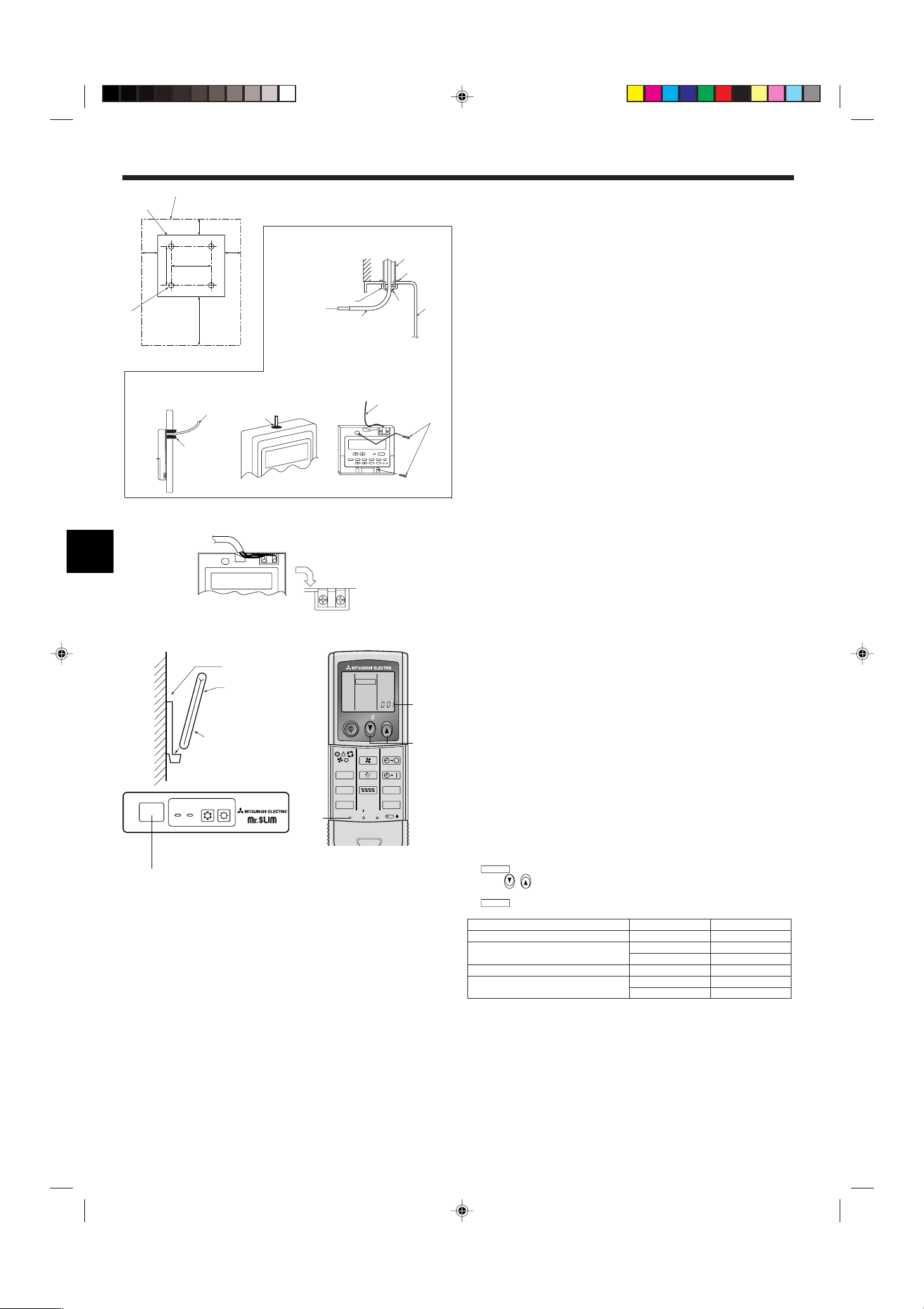
6. Elektroarbeiten
MODEL SELECT
MODEL SELECT
30
46
30
30120
83,5
A
B
C
F
A
H
C
D
E
G
I
I
I
H
B
A
AB TB6
B
ON/OFF TEMP
FAN
VANE
TEST RUN
AUTO STOP
AUTO START
h
min
LOUVER
MODE
CHECK
RESETSET CLOCK
MODEL SELECT
2,4
3
A
J
H
B
1
C
A
2
ON
OFF
STAND
BY
COOL HEAT
D
Fig. 6-2
B-1. B-2.
Fig. 6-3
Fig. 6-4
6.2. Fernbedienung
6.2.1. Für die verdrahtete Fernbedienung
1) Installationsabläufe
(1) Aufstellungsort für Fernbedienung auwählen. (Fig. 6-2)
Die Temperaturfühler befinden sich sowohl an der Fernbedienung als auch an der Innenanlage.
s Folgende Teile vor Ort beschaffen:
Schaltkasten für zwei Teile
Dünnes Kupferleitungsrohr
Kontermuttern und Buchsen/Leitungsdurchführungen
A Form der Fernbedienung
B Erforderliche Freiräume um die Fernbedienung herum
C Installationsteilung
(2) Den Wartungszugang des Fernbedienungskabel mit Kitt oder Dichtungsmittel abdich-
ten, um das mögliche Eindringen von Tau, Wasser, Kakerlaken oder Würmern und Raupen zu verhindern. (Fig. 6-3)
A Zur Installation des Schaltkasten:
B Bei Installation direkt an der Wand wie folgt vorgehen:
• Ein Loch für das Anschlußkabel der Fernbedienung durch die Wand brechen (damit das
Kabel der Fernbedienung von hinten durchgeführt werden kann), dann das Loch mit Kitt
abdichten.
• Das Fernbedienungskabel durch einen Einschnitt im oberen Gehäuse führen, dann den
Einschnitt in ähnlicher Weise wie oben mit Kitt abdichten.
B-1. Zur Führung des Fernbedienungskabels von der Rückseite der Steuerung:
B-2. Zur Führung des Fernbedienungskabels durch die Oberseite:
(3) Bei Installation direkt an der Wand
C Wand/Mauer
D Rohrleitung
E Kontermutter
F Buchse
G Schaltkasten
H Kabel der Fernbedienung
I Mit Kitt abdichten
J Holzschraube
2) Anschlußverfahren (Fig. 6-4)
1 Das Fernbedienungskabel am Klemmenblock anschließen.
A Zu TB5 an der Innenanlage
B TB6 (Keine Polarität)
3) Einstellung für zwei Fernbedienungen
Wenn zwei Fernbedienungen angeschlossen sind, stellen Sie eine auf “Hauptgerät” und
die andere auf “Nebengerät”. Für die entsprechende Einstellung lesen Sie den Abschnitt
“Funktionsauswahl” in der Bedienungsanleitung des Innengerätes.
Fig. 6-5
Fig. 6-6
6.2.2. Für die drahtlose Fernbedienung
1) Aufstellort
• Aufstellort der Fernbedienung darf nicht direktem Sonnenlicht ausgesetzt sein.
• Aufstellort der Fernbedienung darf nicht zu nah an Heizquellen liegen.
• Aufstellort der Fernbedienung darf keinen kalten (oder heißen) Luftströmen ausgesetzt
sein.
• Aufstellort der Fernbedienung muß einfache Bedienung erlauben.
• Aufstellort der Fernbedienung muß außer Reichweite von Kindern liegen.
2) Aufstellverfahren (Fig. 6-5)
1 Die Halter der Fernbedienung mit zwei Blechschrauben am gewünschten Ort anbrin-
gen.
2 Die Unterseite der Fernbedienung in den Halter einsetzen.
A Fernbedienung
B Wand
C Anzeige
D Empfänger
• Das Signal hat eine Reichweite (in gerader Linie) von etwa 7 Meter in einem Winkel von
45 Grad rechts und links der Mittellinie des Geräts.
3) Einstellung (Fig. 6-6)
1 Batterien einlegen.
2 SET-Taste mit einem spitzen Gegenstand drücken.
3 Temp- -Taste zum Einstellen der Modellnummer drücken.
4 SET-Taste mit einem spitzen Gegenstand drücken.
blinkt und die Modellnummer leuchtet.
und Modellnummer leuchten drei Sekunden lang und werden dann ausge-
schaltet.
Innenanlage Außenanlage A Modell-Nr.
PLH, PCH, PKH (35, 50) PUH 001
PLA, PCA, PKA (35, 50)
PUH, PUHZ, SUZ 001
PU 033
PKH (60, 71, 100) PUH 003
PKA (60, 71, 100)
PUH, PUHZ, SUZ 003
PU 035
22
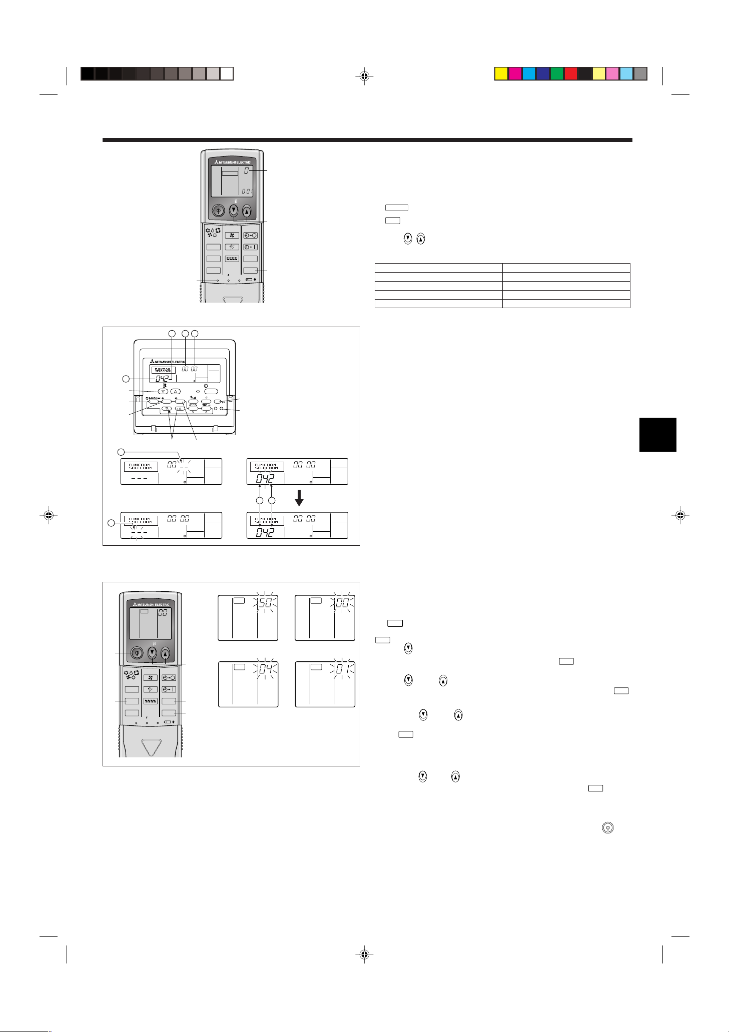
MODEL SELECT
min
CHECK
CHECK
ON/OFF TEMP
FAN
VANE
TEST RUN
AUTO STOP
AUTO START
h
min
LOUVER
MODE
CHECK
RESETSET CLOCK
CHECK
E
C,D
F
A
B
CHECK
CHECK
ON/OFF TEMP
FAN
VANE
TEST RUN
AUTO STOP
AUTO START
h
min
LOUVER
MODE
CHECK
RESETSET CLOCK
MODEL SELECT
1,4
3
A
2
PAR-21MAA
ON/OFF
FILTER
CHECK
OPERATION
CLEAR
TEST
TEMP.
MENU
BACK DAY
MONITOR/SET
CLOCK
ON/OFF
A
B
DC
G
E
F
4
1
213 4
1 2
CHECK
CHECK
h
min
h
h
6. Elektroarbeiten
Fig. 6-7
Fig. 6-8
1
3
Fig. 6-9
1
⁄ Betriebsart-Nummer
2
⁄ Einstell-Nummer
3
⁄ Kältemittel-Adresse
4
⁄ Anlagen-Nummer
2
4
4) Zuweisung einer Fernbedienung für jede einzelne Anlage (Fig. 6-7)
Eine einzelne Anlage kann nur von der zugewiesenen Fernbedienung gesteuert werden.
Sicherstellen, daß jede PC-Tafel einer Innenanlage der richtigen Zuordnungsnummer der
Fernbedienung zugewiesen ist.
5) Vorgehensweise zur Einstellung der Paarnummer der drahtlosen Fernbedienung
1 SET-Taste mit einem spitzen Gegenstand drücken.
Nehmen Sie diesen Schritt vor, wenn das Fernbedienungsdisplay gestoppt ist.
blinkt und die Modellnummer leuchtet.
-Taste zweimal kurz nacheinander drücken.
2
Die Nummer “0” blinkt.
3 Temp-
-Taste zum Einstellen der gewünschten Paarnummer drücken.
4 SET-Taste mit einem spitzen Gegenstand drücken.
Die gewählte Paarnummer leuchtet drei Sekunden lang und wird dann ausgeschaltet.
A Paar-Nr der drahtlosen Fernbedienung PC-Tafel der Innenanlage
0 Werksseitige Einstellung
1 Schnitt J41
2 Schnitt J42
3-9 Schnitt J41, J42
6.3. Funktionseinstellungen
6.3.1. Funktionseinstellung an der Anlage (Wahl der Funktionen der
Anlage)
1) Für die verdrahtete Fernbedienung (Fig. 6-8)
Die Netzspannungseinstellung ändern
• Dafür sorgen, daß die Netzspannungseinstellung je nach verwendeter Spannung geän-
dert wird.
1 Zum Funktionseinstellmodus gehen.
Fernbedienung ausschalten.
Drücken Sie die Tasten A und B gleichzeitig, und halten Sie diese mindestens
2 Sekunden lang gedrückt. FUNCTION beginnt zu blinken.
2 Mit der Taste C die Kältemittel-Adresse (3) auf 00 einstellen.
3 Drücken Sie D, und [--] beginnt im Anlagennummer-Display (4) zu blinken.
4 Setzen Sie die Anlagennummer (4) mit der Taste C auf 00.
5 Die Taste E MODE drücken, um die Kältemittel-Adresse/Anlagennummer zu bestim-
men. [--] blinkt im Modusnummer (1) Display kurzzeitig.
6 Die Taste F drücken, um die Betriebsartennummer (1) auf 04 zu stellen.
7 Drücken Sie die Taste G, und die momentan gewählte Einstellnummer (2) beginnt zu
blinken.
Schalten Sie mit der Taste F die Einstellnummer entsprechend der verwendeten Netzspannung um.
Netzspannung
240 V : Eingestellnummer = 1
220 V, 230 V : Eingestellnummer = 2
8 Drücken Sie die MODE-Taste E, und die Betriebsart- und Einstellnummern (1) und
(2) werden stetig (nicht-blinkend) angezeigt, und die vorgenommenen Einstellungen
können überprüft werden.
9 Die Tasten FILTER A und TEST RUN B gleichzeitig drücken und mindestens zwei
Sekunden lang gedrückt halten. Das Funktionswahlbild verschwindet kurzzeitig, und
die Anzeige Klimaanlage OFF erscheint.
2) Für die drahtlose Fernbedienung (Fig. 6-9)
Die Netzspannungseinstellung ändern
• Immer die Netzspannungseinstellung je nach verwendeter Spannung ändern.
1 Gehe zu der Betriebsart Funktionswahl
Die
-Taste F zweimal kurz nacheinander drücken.
(Nehmen Sie diesen Schritt vor, wenn das Fernbedienungsdisplay gestoppt ist.)
leuchtet und “00” blinkt.
Die temp-
nung auf den Empfangssensor der Innenanlage richten und die
-Taste C zur Einstellung von “50” einmal drücken. Die drahtlose Fernbedie-
-Taste A drücken.
2 Einstellung der Anlagennummer
Die temp-
C und D-Taste zur Einstellung der Anlagennummer “00” drücken. Die
drahtlose Fernbedienung auf den Empfangssensor der Innenanlage richten und die
Taste B drücken.
3 Eine Betriebsart wählen
Mit den Tasten
, C und , D 04 eingeben, um die Einstellung der Betriebsspannung
zu ändern. Die drahtlose Fernbedienung auf den Empfangssensor der Innenanlage richten
und die
-Taste A drücken.
Derzeitige Einstellungsnummer: 1 = 1 Piepton (eine Sekunde)
2 = 2 Pieptöne (je eine Sekunde)
3 = 3 Pieptöne (je eine Sekunde)
4 Wahl der Einstlelnummer
Mit den Tasten
drahtlose Fernbedienung auf den Sensor der Innenanlage richten und die
C und D die Netzspannungseinstellung auf 01 (240 V) ändern. Die
-Taste A
drücken.
5 Mehrfachfunktionen fortlaufend wählen
Schritte 3 und 4 wiederholen, um Einstellungen für Mehrfachfunktionen fortlaufend zu ändern.
6 Funktionswahl abschließen
Die drahtlose Fernbedienung auf den Sensor der Innenanlage richten und die
-Taste
E drücken.
Hinweis:
Jede Änderung, die nach Installation oder Wartung an den Funktionseinstellungen
vorgenommen wird, muss unbedingt mit einer Kennzeichnung in der Spalte “Ein-
stellung” der Funktionstabelle vermerkt werden.
6.3.2. Funktionseinstellung auf der Fernbedienung
Siehe dazu Bedienungsanleitung der Innenanlage.
23
-
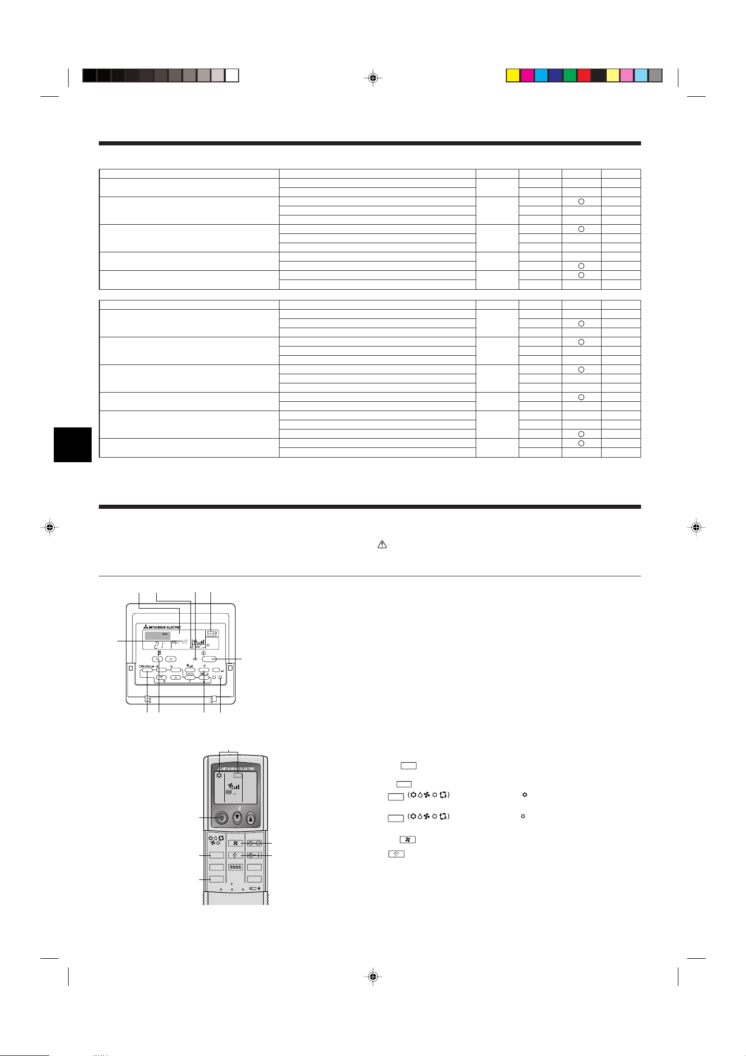
6. Elektroarbeiten
ON/OFF TEMP
FAN
VANE
TEST RUN
AUTO STOP
AUTO START
h
min
LOUVER
MODE
CHECK
RESETSET CLOCK
TEST RUN
5
7
A
3,4
2
6
˚C
˚C
SIMPLE
PAR-21MAA
ON/OFF
FILTER
CHECK
OPERATION
CLEAR
TEST
TEMP.
MENU
BACK DAY
MONITOR/SET
CLOCK
ON/OFF
TEST RUN
COOL, HEAT
A
FCEDB
M
IH G
TEST RUN
TEST RUN
MODE
COOL
MODE
HEAT
FAN
VANE
Funktionstabelle
Anlage Nr. 00 wählen
Betriebsart
Automatische Wiederherstellung nach Netzstromausfall
Erkennung der Innentemperatur
LOSSNAY-Verbindung
Netzstrom
Automatikbetrieb
(nur für PUHZ)
Anlagenummern 01 bis 03 oder alle Anlagen wählen (AL [verdrahtete Fernbedienung] / 07 [drahtlose Fernbedienung])
Betriebsart
Filterzeichen
Gebläsegeschwindigkeit
Anzahl der Luftauslässe
Installierte Optionen (Hochleistungsfilter)
Auf/ab Flügelzellen-Einstellung
Stromsparender Luftstrom
(Heizbetrieb)
*1 Wenn der Netzstrom wieder anliegt, läuft die Klimaanlage nach 3 Minuten wieder an.
*2 Die Grundeinstellung von Automatische Wiederherstellung nach Netzstromausfall hängt von der angeschlossenen Außenanlage ab.
Einstellungen
Nicht verfügbar
Verfügbar
*1
Betriebsdurchschnitt der Innenanlage
Einstellung durch Fernbedienung der Innenanlage
Interner Sensor der Fernbedienung
Nicht unterstützt
Unterstützt (Innenanlage nicht mit Außen-Lufteinlaß ausgestattet)
Unterstützt (Innenanlage mit Außen-Lufteinlaß ausgestattet)
240 V
220 V, 230 V
Stromsparzyklus ist automatisch eingeschaltet
Stromsparzyklus ist automatisch ausgeschaltet
Einstellungen
100 Std.
2500 Std.
Keine Filterzeichenanzeige
Standard (PLH/PLA)/Leise (PCH/PCA)
Hohe Decke 1 (PLH/PLA)/Standard (PCH/PCA)
Hohe Decke 2 (PLH/PLA)/Maximum (PCH/PCA)
4 Richtungen
3 Richtungen
2 Richtungen
Nicht unterstützt
Unterstützt
Keine Flügelzellen
Mit Flügelzellen (Einstellung des Flügelzellenwinkels 1)
Mit Flügelzellen (Einstellung des Flügelzellenwinkels 2)
Ausgeschaltet
Eingeschaltet
Betriebsart Nr. Einstellung Nr.
01
1*2
2*2
1
02 2
3
1
03 2
3
04
05
1
2
1
2
Betriebsart Nr. Einstellung Nr.
1
07 2
3
1
08 2
3
1
09 2
3
10
1
2
1
11
2
3
12
1
2
Grundeinstellung
Grundeinstellung
Einstellung
Einstellung
7. Testlauf
7.1. Vor dem Testlauf
s Nach Installierung, Verdrahtung und Verlegung der Rohrleitungen der In- nen-
und Außenanlagen überprüfen und sicherstellen, daß kein Kältemittel ausläuft,
Netzstromversorgung und Steuerleitungen nicht locker sind, Polarität nicht falsch
angeordnet und keine einzelne Netzanschlußphase getrennt ist.
s Mit einem 500-Volt-Megohmmeter überprüfen und sicherstellen, daß der Widerstand
zwischen Stromversorgungsklemmen und Erdung mindestens 1,0 M
24
Fig. 7-1
Fig. 7-2
ΩΩ
Ω beträgt.
ΩΩ
A Taste ON/OFF
B Testlaufanzeige
C Temperaturanzeige der
Innenanlagenflüssigkeitsleitung
D Lampe ON/OFF
E Bereitschaftsanzeige
F Fehlercodeanzeige
Anzeige der verbleibenden
Testlaufzeit
G Temperaturwahltaste
H Betriebsartwahltaste
I Gebläsegeschwindigkeitstaste
M Taste TEST
s Diesen Test nicht an den Klemmen der Steuerleitungen (Niederspannungs-
stromkreis) vornehmen.
Warnung:
Die Klimaanlage nicht in Betrieb nehmen, wenn der Isolationswiderstand weniger als
ΩΩ
1,0 M
Ω beträgt.
ΩΩ
Isolationswiderstand
7.2. Testlauf
Die nachstehenden 3 Verfahren sind verfügbar.
7.2.1. Verwendung der verdrahteten Fernbedienung (Fig. 7-1)
1 Den Strom mindestens 12 Stunden vor dem Testlauf einschalten.
2 Die [TEST]-Taste zweimal drücken. ➡ “TEST RUN”-Flüssigkristallanzeige (LCD)
3 Taste [Mode selection] (Wahl der Betriebsart) drücken. ➡ Vergewissern, daß Luft aus-
geblasen wird.
4 Taste [Mode selection] (Wahl der Betriebsart) drücken und die Betriebsart Kühlen (oder
Heizen) einschalten. ➡ Vergewissern, daß kalte (oder warme) Luft ausgeblasen wird.
5 Die Taste [Fan speed] (Luftgeschwindigkeit) drücken. ➡ Vergewissern, daß die Luft-
geschwindigkeit eingeschaltet ist.
6 Den Betrieb des Gebläses der Außenanlage überprüfen.
7 Durch Drücken der Taste [ON/OFF] (EIN/AUS) den Testlauf freigeben. ➡ Stopp
8 Speichern Sie eine Telefonnummer ein.
Die Telefonnummer eines Reparaturbetriebs, Verkaufsbüros usw. kann für eine Kontaktaufnahme bei auftretenden Fehlern in die Fernbedienung eingespeichert werden.
Die Telefonnummer wird angezeigt, wenn ein Fehler aufgetreten ist. Für Anweisungen
für die Eingabe dieser Nummer lesen Sie die Bedienungsanleitung des Innengerätes.
7.2.2. Verwendung der drahtlosen Fernbedienung (Fig. 7-2)
1 Mindestens 12 Stunden vor dem Testlauf den Netzstrom einschalten.
2 Die
3
4
5 Die
6
7 ON/OFF (netzstrom EIN/AUS)-Taste drücken, um Probelauf zu beenden.
Hinweis:
• Bei Ausführung der Schritte 2 bis 7 die Fernbedienung auf das Empfangsteil der
Innenanlage richten.
• Es ist nicht möglich, das Gerät in den Betriebsarten FAN, DRY oder AUTO arbeiten
zu lassen.
-Taste zweimal kurz nacheinander drücken.
(Nehmen Sie diesen Schritt vor, wenn das Fernbedienungsdisplay gestoppt ist.)
A
(TESTLAUF) und die aktuelle Betriebsart werden angezeigt.
-Taste drücken, um
(Kühlen)-Betrieb zu aktivieren. Dann
prüfen, ob Kaltluft aus der Anlage geblasen wird.
-Taste drücken, um
(Heizung) zu aktivieren. Dann prüfen,
ob Warmluft aus der Anlage geblasen wird.
-Taste (Gebläse) drücken und überprüfen ob sich die Gebläsedrehzahl ändert.
(gebläseflügel)-Taste drücken und prüfen, ob die automatische Gebläseflügel-
Funktion einwandfrei arbeitet.
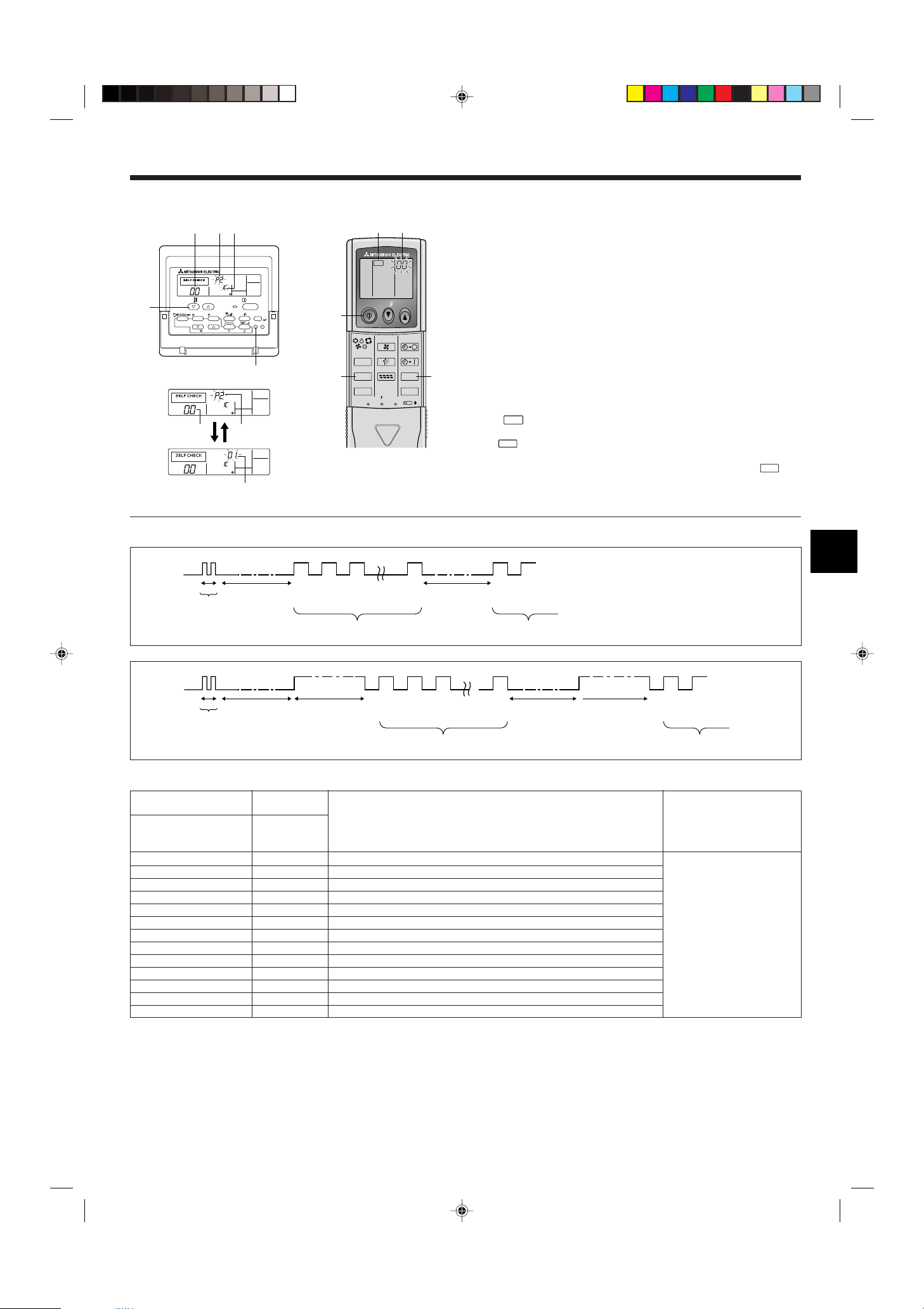
CHECK
CHECK
7. Testlauf
ON/OFF TEMP
FAN
VANE
TEST RUN
AUTO STOP
AUTO START
h
min
LOUVER
MODE
CHECK
RESETSET CLOCK
CHECK
2
4
A
3
B
PAR-21MAA
ON/OFF
FILTER
CHECK
OPERATION
CLEAR
TEST
TEMP.
MENU
BACK DAY
MONITOR/SET
CLOCK
ON/OFF
ERROR CODE
ERROR CODE
ERROR CODE
C
B
A
B
F
E
E D
7.2.3. SW4 in der Außenanlage verwenden
Siehe Aussenanlagen-Installationsanleitung.
7.3. Selbsttest
7.3.1. Für die verdrahtete Fernbedienung (Fig. 7-3)
1 Den Netzstrom einschalten.
2 Die [CHECK] (PRÜFEN)-Taste zweimal drücken
3 Bei Verwendung der System-Steuerung mit der [TEMP]-Taste die Kältemitteladresse
4 Zum Ausschalten der Selbstprüfung die [ON/OFF] (EIN/AUS)-Taste drücken.
7.3.2. Für die drahtlose Fernbedienung (Fig. 7-4)
1 Den Netzstrom einschalten.
2 Die
Fig. 7-4
Fig. 7-3
• Beachten Sie die folgenden Tabellen für Näheres zu den Prüf-Codes. (Drahtlose Fernbedienung )
[Ausgabemuster A]
Piepton erklingt
Blinkmuster der
BETRIEBSANZEIGE-Lampe
[Ausgabemuster B]
Piepton erklingt
Blinkmuster der
BETRIEBSANZEIGE-Lampe
Piep
Selbsttest
beginnt
(Startsignal
empfangen)
Aus
Etwa 2,5 Sek.
Piep Piep Piep Piep Piep Piep
Ein
0,5 Sek.
n-tes Blinken
Etwa 2,5 Sek.
1. 2. 3.
Ein
Ein
0,5 Sek.
Ein
0,5 Sek.
0,5 Sek.
Anzahl der Blinksignale/Pieptöne im Muster zeigt den Prüf-
Code in folgender Tabelle an (z. B. ist n = 5 für “P5”)
Piep Piep Piep Piep Piep Piep Piep
1. 2. 3. 1. 2.
Selbsttest
beginnt
(Startsignal
empfangen)
Aus
Etwa 2,5 Sek.
Ein
Etwa 3 Sek.
Ein
Ein
0,5 Sek.
0,5 Sek.
0,5 Sek.
Anzahl der Blinksignale/Pieptöne im Muster zeigt den
Prüf-Code in folgender Tabelle an (z. B. ist n = 5 für “P5”)
3 Die Fernbedienung auf das Empfangsteil des Gerätes richten und die Taste h drük-
4 ON/OFF (netzstrom EIN/AUS)-Taste drücken, um Selbsttest zu beenden.
Aus
Ein
einstellen.
A CHECK(PRÜFEN)-Taste
B Kältemitteladdresse
C TEMP-Taste
D IC: Innenanlage
OC: Außenanlage
E Check-Code
F Adresse der Anlage
(PRÜFEN)-Taste zweimal drücken
(Nehmen Sie diesen Schritt vor, wenn das Fernbedienungsdisplay gestoppt ist.)
A
(PRÜFEN) leuchtet.
B “00” beginnt zu blinken.
ken. Der Prüfcode wird durch die Anzahl der Tonsignale des Summers aus dem Empfangsbereich und die Anzahl der Blinkvorgänge der Betriebslampe angezeigt.
1. 2.
Ein
0,5 Sek.
Anzahl der Blinksignale/Pieptöne im Muster
zeigt den Prüf-Code in folgender Tabelle an
Ein
0,5 Sek.
· · · Wiederholt
Ein
0,5 Sek.
n-tes Blinken
Aus
Etwa 2,5 Sek.
Ein
Etwa 3 Sek.
· · · Wiederholt
Ein
0,5 Sek.
Anzahl der Blinksignale/Pieptöne im Muster
zeigt den Prüf-Code in folgender Tabelle an
Ein
0,5 Sek.
[Ausgabemuster A] Fehler erkannt am Innengerät
Drahtlose Fernbedienung
Piepton erklingt/BETRIEBSAN-
ZEIGE-Lampe blinkt
(Anzahl von Malen)
1 P1 Fehler Lufteinlassensor
2 P2, P9 Fehler Rohrsystemsensor (Flüssigkeitsseite oder 2-Phasen-Rohr)
3 E6, E7 Kommunikationsfehler zwischen Innen-/Außengerät
4 P4 Fehler Drainagesensor
5 P5 Fehler Drainagepumpe
6 P6 Betrieb bei Vereisungs-/Überhitzungsschutz
7 EE Kommunikationsfehler zwischen Innen- und Außengeräten
8 P8 Fehler Rohrtemperatur
9 E4 Fehler bei Empfang des Fernbedienungssignals
10 ––
11 ––
12 Fb Fehler im Steuersystem des Innengeräts (Fehler im Speicher usw.)
Kein Geräusch – – Keine Entsprechung
Verdrahtete
Fernbedienung
Symptom Bemerkung
Prüf-Code
25
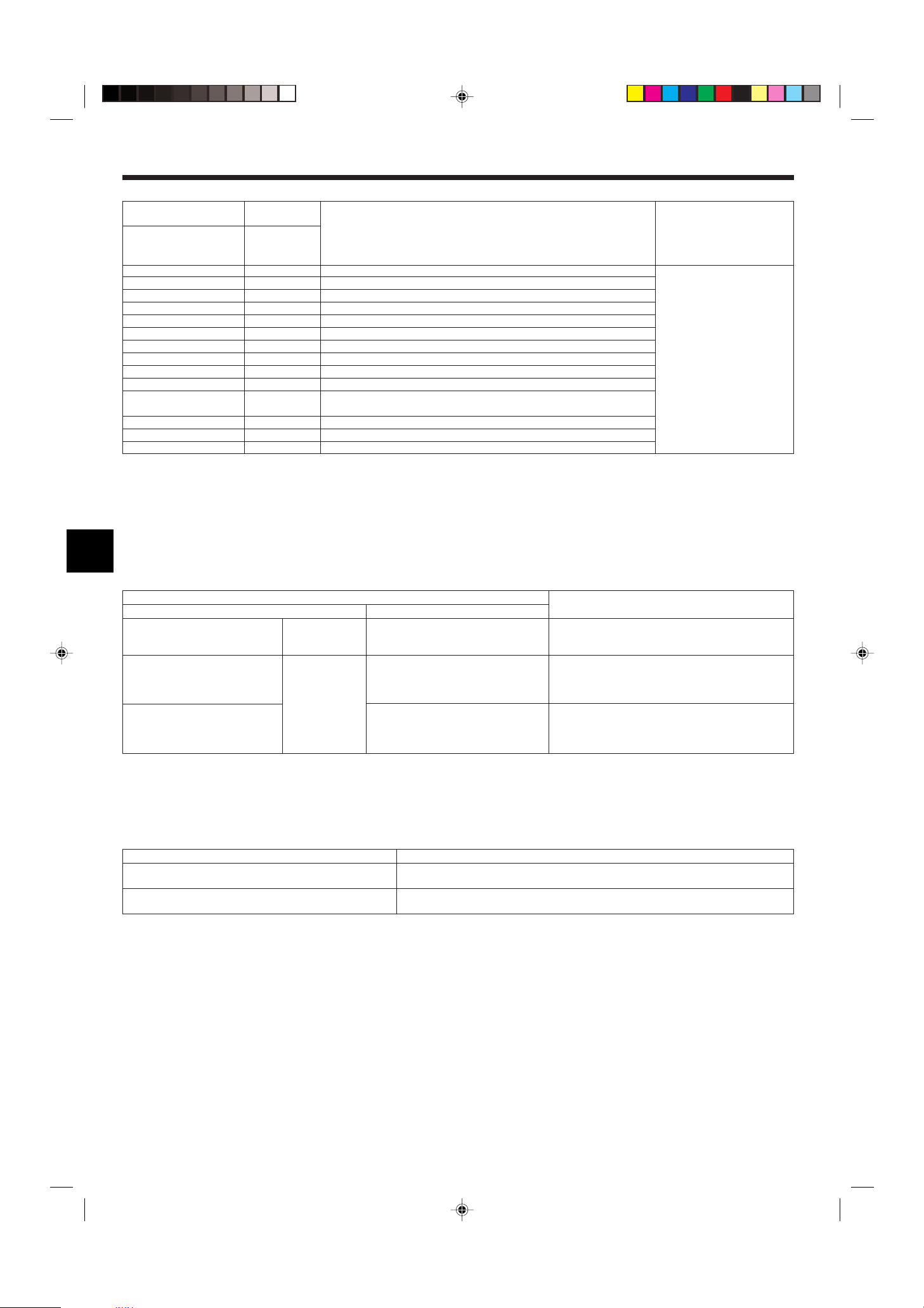
7. Testlauf
[Ausgabemuster B] Fehler erkannt an anderen Geräten als dem Innengerät (Außengerät usw.)
Drahtlose Fernbedienung
Piepton erklingt/BETRIEBSAN-
ZEIGE-Lampe blinkt
(Anzahl von Malen)
1 E9 Kommunikationsfehler zwischen Innen-/Außengerät (Übertragungsfehler) (Außengerät)
2 UP Kompressorunterbrechung wg. Überlaststrom
3 U3, U4 Offener/Kurzgeschlossener Kontakt der Thermistoren des Außengeräts
4 UF Kompressorunterbrechung wg. Überlaststrom (bei verriegeltem Kompressor)
5 U2 Anormal hohe Entladetemperatur/49C-Betrieb/nicht genügend Kühlmittel
6 U1, Ud Anormal hoher Druck (63H-Betrieb)/Betrieb bei Überhitzungsschutz
7 U5 Anormale Temperatur des Kühlkörpers
8 U8 Sicherheitsstop des Lüfters des Außengerätes
9 U6 Kompressorunterbrechung wg. Überlaststrom/Abnormität im Stromversorgungsmodul
10 U7 Abnormität der Überhitzung aufgrund geringer Entladetemperatur
11 U9, UH Abnormität einer Überspannung oder Kurzschluß und anormales Synchronsignal zum
12 ––
13 ––
14 Sonstige Andere Fehler (bitte lesen Sie in der Technischen Anleitung für das Außengerät nach.)
*1 Wenn der Piepton (nach den ersten beiden Pieptönen zur Bestätigung des Empfangs des Startsignals für den Selbsttest) nicht nochmals erklingt, und wenn die BETRIEBSANZEIGE-
Lampe nicht aufleuchtet, gibt es keine Fehleraufzeichnungen.
*2 Wenn der Piepton (nach den ersten beiden Pieptönen zur Bestätigung des Empfangs des Startsignals für den Selbsttest) dreimal nacheinander “Piep, Piep, Piep” (0,4 + 0,4 + 0,4 Sek.)
ertönt, ist die angegebene Kühlmitteladresse falsch.
• Bei der drahtlosen Fernbedienung
Dauersignalton von der Empfangseinheit der Innenanlage.
Blinken der Betriebsanzeige
• Bei der verdrahteten Fernbedienung
Überprüfen Sie den auf dem LCD angezeigten Code.
• Wenn das Gerät nach dem obigen Probelauf nicht richtig betrieben werden kann, siehe folgende Tabelle zum Beheben der Ursache.
Verdrahtete Fernbedienung LED 1, 2 (Leiterplatte in Außenaggregat)
PLEASE WAIT
PLEASE WAIT → Fehlercode
Auf dem Display erscheinen keine Meldungen, auch wenn das Gerät eingeschaltet
ist (Betriebsanzeige leuchtet nicht).
Verdrahtete
Fernbedienung
Prüf-Code
Für etwa 2 Minuten
nach dem Einschalten.
Wenn etwa 2
Minuten nach dem
Einschalten
vergangen sind.
Hauptkreis/Fehler Stromsensor
Symptom
LED 1 und 2 leuchten auf, dann LED 2 wird ausgeschaltet, nur LED 1 leuchtet. (Korrekter Betrieb)
Nur LED 1 leuchtet. → LED 1 und 2 blinken.
Nur LED 1 leuchtet. → LED 1 blinkt zweimal,
LED 2 blinkt einmal.
Symptom Bemerkung
Näheres erfahren Sie durch das
LED-Display der Steuerplatine des
Außengerätes.
Ursache
• Für etwa 2 Minuten nach dem Einschalten ist der Betrieb der
Fernbedienung aufgrund des Anlagenstarts nicht möglich. (Kor-
rekter Betrieb)
• Der Steckverbinder für das Schutzgerät des Außenaggregats ist
nicht angeschlossen.
• Phasenverkehrt oder offene Phasenverdrahtung für Betriebs-
strom-Klemmenblock (L1, L2, L3)
• Falsche Verdrahtung zwischen Innen- und Außenaggregat (fal-
sche Polung von S1, S2, S3)
• Kurzschluß des Fernbedienungskabels
Bei der drahtlosen Fernbedienung im obigen Betriebszustand treten folgende Erscheinungen auf.
• Keine Signale von der Fernbedienung werden akzeptiert.
• OPE-Lämpchen blinkt.
• Der Signaltongeber gibt einen kurzer Piepton aus.
Hinweis:
Für etwa 30 Sekunden nach Beenden der Funktionswahl ist der Betrieb nicht möglich. (Korrekter Betrieb)
Eine Beschreibung jeder LED (LED 1, 2, 3), die mit der Steuerung der Innenanlage geliefert wurde, findet sich in der nachstehenden Tabelle.
LED 1 (Betriebsstrom für Mikrocomputer) Zeigt an, ob Steuerstrom anliegt. Sicherstellen, daß die LED immer leuchtet.
LED 2 (Betriebsstrom für Fernbedienung) Zeigt an, ob Strom an der Fernbedienung anliegt. Diese LED leuchtet nur bei einem Innenaggregat, daß an
LED 3 (Kommunikation zwischen Innenaggregat und Außenaggregat) Zeigt den Zustand der Kommunikation zwischen Innenaggregaten und Außenaggregaten an. Sicherstel-
das Außenaggregat mit der Kältemitteladresse “0” angeschlossen ist.
len, daß diese LED immer blinkt.
26
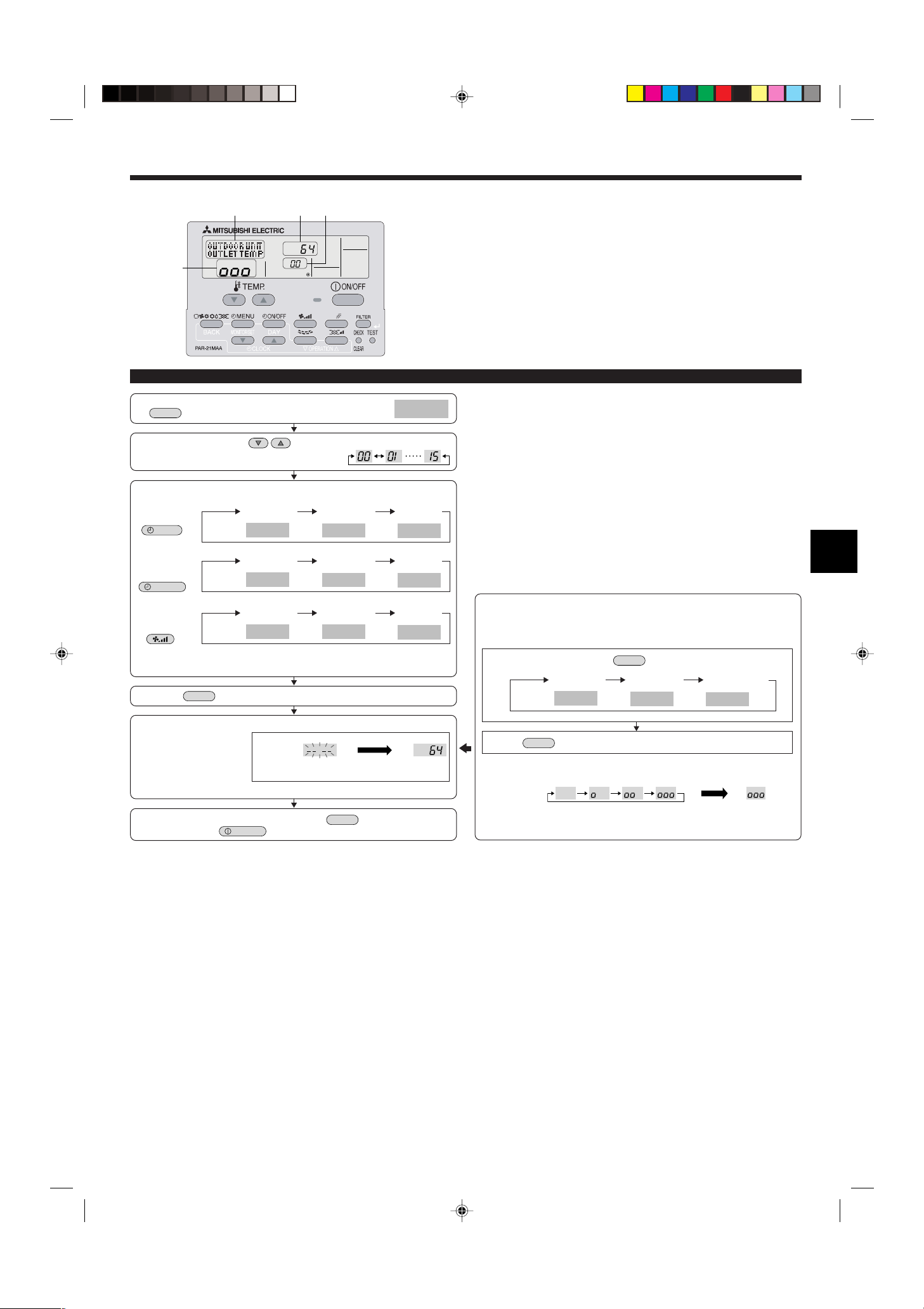
TEST
MAINTENANCE
MENU
ON/OFF
COMP ON
x10 HOURS
COMP ON
x100 TIMES
COMP ON
CURRENT (A)
OUTDOOR UNIT
H·EXC. TEMP
OUTDOOR UNIT
OUTLET TEMP
OUTDOOR UNIT
OUTDOOR TEMP
INDOOR UNIT
INLET TEMP
INDOOR UNIT
H·EXC. TEMP
INDOOR UNIT
FILTER USE H
FILTER
TEST
ON/OFF
COOL
STABLE MODE
HEAT
STABLE MODE
STABLE MODE
CANCEL
MODE
FILTER
8. Funktion für einfache Wartung (option)
D
A
C B
Anzeigebeispiel (Komp. Ablasstemperatur 64 °C)
Betriebsabläufe im Wartungsmodus
(1) Zur Aktivierung des Wartungsmodus die Taste
3 Sekunden lang drücken.
(2) Die TEMP drücken. Tasten zur Einstellung der Kältemitteladresse.
Anzeige B
(3) Wählen Sie die Daten, die Sie anzeigen möchten.
Anzeige
Summierte
Betriebszeit
Kompressorinformationen
A
Temperatur des
AußenanlageInformationen
Innenanlageinformationen
* Die angezeigte Betriebszeit des Filters gibt die Zahl der Stunden an, die der Filter
seit seinem Wiedereinsetzen genutzt wurde.
(4) Die Taste
Anzeige
A
Anzeige
A
drücken.
Wärmetauschers
Innenraum-
temperatur
Anzeige A
ON/OFF (EIN/
AUS) Zahl
Komp.
Ablasstemperatur
Temperatur des
Wärmetauschers
Betriebsstrom
Temperatur der
Außenumgebung
Betriebszeit
des Filters
Im Wartungsmodus können Sie viele Arten von Wartungsdaten auf der Fernbedienung, wie
etwa Temperatur des Wärmetauschers und Stromverbrauch des Kompressors für die Innen- und Außenanlagen, anzeigen.
Diese Funktion kann unabhängig davon genutzt werden, ob die Klimaanlage läuft oder
nicht.
Während des Betriebs der Klimaanlage können die Daten sowohl im Normalbetrieb als
auch im konstanten Betrieb des Wartungsmodus überprüft werden.
* Diese Funktion kann im Testlauf nicht genutzt werden.
* Die Verfügbarkeit dieser Funktion ist abhängig von der angeschlossenen Außenanlage.
Bitte Prospekte beachten.
Konstanter Betrieb
Im Wartungsmodus kann die Betriebshäufigkeit festgelegt und der Betrieb konstant
gehalten werden. Wenn die Klimaanlage ausgeschaltet ist, diese Betriebsart mit folgendem Verfahren starten.
Zur Wahl der Betriebsart die Taste
Konstanter
Kühlbetrieb
Anzeige
A
drücken.
Konstanter
Heizbetrieb
Abbruch des
konstanten Betriebs
(5) Die Daten werden in C angezeigt.
(Beispiel für die Anzeige der Temperatur des Luftstroms)
Anzeige C
Blinken
Auf Reaktion
warten
Etwa 10
Sek.
* Zur Prüfung eines weiteren Datums Schritte (2) bis (5) wiederholen.
(6) Zum Ausschalten des Wartungsmodus die Taste
ken oder die Taste
drücken.
drei Sekunden lang drük-
64 °C
Die Taste
Warten auf
konstanten Betrieb
Anzeige
D
* Beim Warten auf den konstanten Betrieb können Sie mit den Schritten (3) bis (5) die
Daten des Betriebsablaufs des Wartungsmodus überprüfen.
drücken.
10-20 Min.
Konstanter
Betrieb
27

Index
1. Consignes de sécurité ........................................................................... 28
2. Emplacement pour l’installation ............................................................. 29
3. Installation de l’appareil intérieur ........................................................... 29
4. Installation de la tuyauterie du réfrigérant .............................................. 31
1. Consignes de sécurité
s Avant d’installer le climatiseur, lire attentivement toutes les “Consignes de
sécurité”.
ss
s Veuillez consulter ou obtenir l’autorisation de votre compagnie d’électricité
ss
avant de connecter votre système.
Avertissement:
Précautions à suivre pour éviter tout danger de blessure ou de décès de l’utilisateur.
Précaution:
Décrit les précautions qui doivent être prises pour éviter d’endommager l’appareil.
Avertissement:
• Contacter un revendeur ou un technicien agréé pour installer l’appareil.
• Pour l’installation, respecter les instructions du manuel d’installation et utiliser
des outils et des composants de tuyau spécialement conçus pour une utilisation
avec le réfrigérant spécifié dans le manuel d’installation de l’appareil extérieur.
• L’appareil doit être installé conformément aux instructions pour réduire les risques de dommages liés à des tremblements de terre, des typhons ou des vents
violents. Une installation incorrecte peut entraîner la chute de l’appareil et provoquer des dommages ou des blessures.
• L’appareil doit être solidement installé sur une structure pouvant supporter son
poids.
• Si le climatiseur est installé dans une petite pièce, certaines mesures doivent être
prises pour éviter que la concentration de réfrigérant ne dépasse le seuil de sécurité en cas de fuite. En cas de fuite de réfrigérant et de dépassement du seuil de
concentration, des risques liés au manque d’oxygène dans la pièce peuvent survenir.
5. Mise en place du tuyau d’écoulement ................................................... 32
6. Installations électriques ......................................................................... 33
7. Marche d’essai ....................................................................................... 37
8. Fonction d’entretien aisé (en option)...................................................... 40
Une fois l’installation terminée, expliquer les “Consignes de sécurité”, l’utilisation et
l’entretien de l’appareil au client conformément aux informations du mode d’emploi
et effectuer l’essai de fonctionnement en continu pour garantir un fonctionnement normal.
Le manuel d’installation et le mode d’emploi doivent être fournis à l’utilisateur qui doit les
conserver. Ces manuels doivent également être transmis aux nouveaux utilisateurs.
: Indique un élément qui doit être mis à la terre.
Avertissement:
Prendre soin de lire les étiquettes se trouvant sur l’appareil principal.
• Aérer la pièce en cas de fuite de réfrigérant lors de l’utilisation. Le contact du réfrigérant avec une flamme peut provoquer des émanations de gaz toxiques.
• Tout tcavail sur les installations électriques doit être effectué par un technicien
qualifié conformément aux réglementations locales et aux instructions fournies
dans ce manuel.
• N’utiliser que les câbles spécifiés pour les raccordements.
• Le couvercle du bloc de sortie de l’appareil doit être solidement fixé.
• N’utiliser que les accessoires agréés par Mitsubishi Electric et contacter un revendeur ou un technicien agréé pour les installer.
• L’utilisateur ne doit jamais essayer de réparer ou de déplacer l’appareil.
• Une fois l’installation terminée, vérifier les éventuelles fuites de réfrigérant. Si le
réfrigérant fuit dans la pièce et entre en contact avec la flamme d’un chauffage ou
d’une cuisinière, des gaz toxiques peuvent se dégager.
1.1. Avant l’installation (Environnement)
Précaution:
• Ne pas utiliser l’appareil dans un environnement inhabituel. Si le climatiseur est
installé dans des endroits exposés à la vapeur, à l’huile volatile (notamment l’huile
de machine), au gaz sulfurique ou à une forte teneur en sel, par exemple, en bord
de mer, les performances peuvent considérablement diminuer et les pièces internes de l’appareil être endommagées.
• Ne pas installer l’appareil dans des endroits où des gaz de combustion peuvent
s’échapper, se dégager ou s’accumuler. L’accumulation de gaz de combustion
autour de l’appareil peut provoquer un incendie ou une explosion.
• Ne pas placer d’aliments, de plantes, d’animaux en cage, d’objets d’art ou d’instruments de précision dans la soufflerie d’air direct de l’appareil intérieur ou à proximité de l’appareil au risque de les endommager par des variations de température
ou des gouttes d’eau.
1.2. Avant l’installation ou le déplacement
Précaution:
• Transporter les appareils avec précaution. L’appareil doit être transporté par au
moins deux personnes, car il pèse 20 kg minimum. Ne pas le saisir par les rubans
d’emballage. Porter des gants de protection en raison du risque de se blesser les
mains sur les ailettes ou d’autres pièces.
• Veiller à éliminer le matériel d’emballage en toute sécurité. Le matériel d’emballage (clous et autres pièces en métal ou en bois) peut provoquer des blessures.
• Isoler le tuyau de réfrigérant pour éviter la condensation. S’il n’est pas correctement isolé, de la condensation risque de se former.
1.3. Avant l’installation électrique
Précaution:
• Veiller à installer des coupe-circuits. Dans le cas contraire, un choc électrique peut
se produire.
• Pour les lignes électriques, utiliser des câbles standard de capacité suffisante.
Dans le cas contraire, un court-circuit, une surchauffe ou un incendie peut se produire.
• Lors de l’installation des lignes électriques, ne pas mettre les câbles sous tension.
• Si l’humidité ambiante dépasse 80% ou si le tuyau d’écoulement est bouché, des
gouttes d’eau peuvent tomber de l’appareil intérieur. Ne pas installer l’appareil intérieur dans un endroit où ces gouttes peuvent provoquer des dommages.
• Lors de l’installation de l’appareil dans un hôpital ou un centre de communications, se préparer au bruit et aux interférences électroniques. Les inverseurs, les
appareils électroménagers, les équipements médicaux haute fréquence et de communications radio peuvent provoquer un dysfonctionnement ou une défaillance
du climatiseur. Le climatiseur peut également endommager les équipements médicaux et de communications, perturbant ainsi les soins et réduisant la qualité d’affichage des écrans.
• Placer un isolant thermique sur les tuyaux pour éviter la condensation. L’installation incorrecte du tuyau d’écoulement peut provoquer des fuites d’eau et endommager le plafond, le sol, les meubles ou d’autres objets.
• Ne pas nettoyer le climatiseur à l’eau au risque de provoquer un choc électrique.
• Serrer tous les écrous évasés conformément aux spécifications à l’aide d’une clé
dynamométrique. S’ils sont trop serrés, ils peuvent casser après une période prolongée.
• Veiller à mettre l’appareil à la terre. Une mise à la terre incorrecte de l’appareil peut
provoquer un choc électrique.
• Utiliser des coupe-circuits (disjoncteur de fuite à la terre, interrupteur d’isolement
(fusible +B) et disjoncteur à boîtier moulé) à la capacité spécifiée. Si la capacité du
coupe-circuit est supérieure à celle spécifiée, une défaillance ou un incendie peut
se produire.
1.4. Avant la marche d’essai
Précaution:
• Activer l’interrupteur principal au moins 12 heures avant la mise en fonctionnement de l’appareil. L’utilisation de l’appareil juste après sa mise sous tension peut
endommager sérieusement les pièces internes.
• Avant d’utiliser l’appareil, vérifier que tous les panneaux, toutes les protections et
les autres pièces de sécurité sont correctement installés. Les pièces tournantes,
chaudes ou à haute tension peuvent provoquer des blessures.
• Ne pas utiliser le climatiseur si le filtre à air n’est pas installé. Sinon, des poussières peuvent s’accumuler et endommager l’appareil.
28
• Ne pas toucher les interrupteurs les mains humides au risque de provoquer un
choc électrique.
• Ne pas toucher les tuyaux de réfrigérant les mains nues lors de l’utilisation.
• A la fin de l’utilisation de l’appareil, attendre au moins cinq minutes avant de désactiver l’interrupteur principal. Dans le cas contraire, une fuite d’eau ou une défaillance peut se produire.
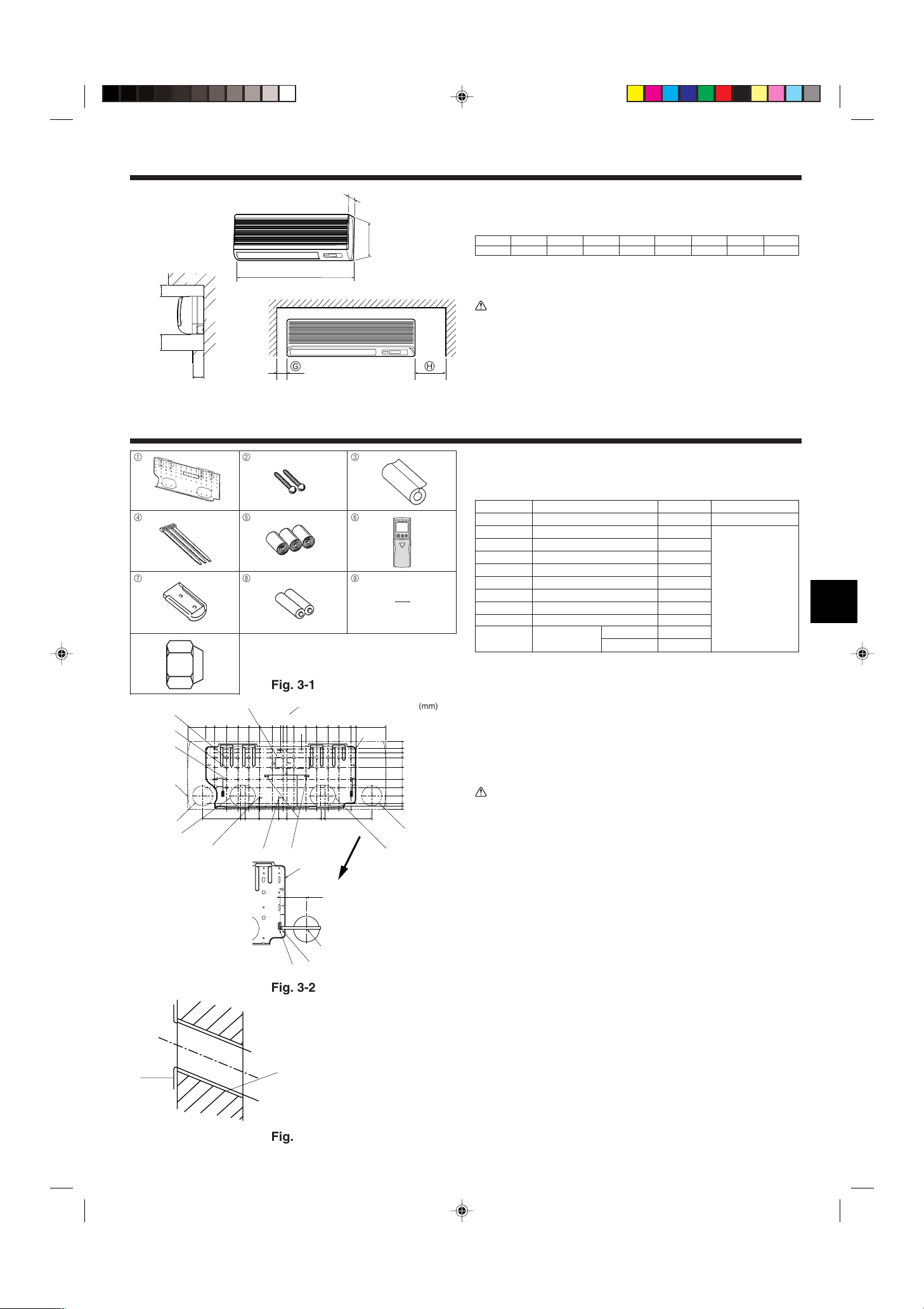
E
D
C
B
A
F
H
D
W
G H
420
495
405
360
300
245
190
135
7532200352595
205
260
320
345
495
150
230
210
140
170
190
425
40
0
0
35
55
80
130
190
230
272
310
340
322
*
A
B
C
D
E
F
G
H
I
J
K
L
M
N
B
Y
Z
V
100
A
C
D
E
B
2. Emplacement pour l’installation
Fig. 2-1
3. Installation de l’appareil intérieur
2.1. Dimensions externes (Appareil intérieur) (Fig. 2-1)
Choisir un emplacement approprié en prenant compte des espaces suivants pour l’installa-
tion et l’entretien.
Modèles W D H AE FGH
35, 50 990 235 340 Min. 30 Max. 130 Min. 180 Min. 50 Min. 150
B Plafond
C Mur
D Meubles, etc.
(mm)
Avertissement:
Fixer l’appareil intérieur à un plafond suffisamment résistant pour supporter son
poids.
2.2. Dimensions extérieures (Appareil extérieur)
Consulter le manuel d’installation de l’appareil extérieur.
1
2
3
3.1. Vérifier les accessoires qui accompagnent
l’appareil intérieur (Fig. 3-1)
L’appareil intérieur doit être livré avec les accessoires suivants:
4
5
6
1 Planche d’installation 1
Numéro d’élément
ACCESSOIRE QUANTITE EMPLACEMENT
Fixer à l’arrière de l’appareil
2 Vis de fixation 4 × 35 12
3 Couvercle des tuyaux 1
4 Bandes 3
7
8
9
5 Ruban de feutre 3
6 Télécommande sans fil 1
7 Support de la télécommande 1
Piles alcalines (de format AAA)
8
Loger à l’intérieur de
l’appareil
2
9 Pièce de montage 1
0
0
Ecrou évasé
RP35, 50
P35, 50 0
2 (ø9,52, ø15,88)
Fig. 3-1
(mm)
3.2. Installation de la structure de montage mural
(Fig. 3-2)
3.2.1. Installation de la structure de montage mural et mise en place des
tuyaux
s A l’aide de la structure de montage mural, déterminer l’emplacement d’installa-
tion de l’appareil et le lieu de forage des orifices pour les tuyaux.
Avertissement:
Avant de forer un trou dans le mur, veuillez demander l’autorisation au responsable
de l’édifice.
A Pièce de support J Fente du tuyau inférieur droit (ø90)
B Planche d’installation K
C Partie principale L Position de la connexion évasée du tuyau de liquide
D Fente (6-11 × 20) M Position de la connexion évasée du tuyau de gaz
E Centre de l’appareil N Norme de nivellement
F Orifice du boulon (14-ø14) V Introduire la balance
G Orifice fileté (49-ø5) Y Orifice central
H
Fente du tuyau inférieur gauche (ø90)
I Orifice pré-coupé pour la fente du tuyau inférieur gauche
Orifice pré-coupé pour la fente du tuyau inférieur droit
Z Aligner la balance avec la ligne.
Fig. 3-2
3.2.2. Forage de l’orifice des tuyaux (Fig. 3-3)
s Utiliser une foreuse à témoins pour forer un orifice de pénétration dans le mur de
90 à 100 mm de diamètre, aligné sur la direction du tuyau, à l’endroit indiqué sur
le diagramme à gauche.
s L’orifice de pénétration dans le mur doit être incliné de telle sorte que l’ouverture
extérieure soit plus basse que l’ouverture intérieure.
A Manchon
B Orifice
C (Côté intérieur)
D Mur
E (Côté extérieur)
s Insérer un manchon (de 90 mm de diamètre - non fourni) dans l’orifice.
Remarque:
L’orifice de pénétration doit être incliné afin d’augmenter le débit.
Fig. 3-3
29
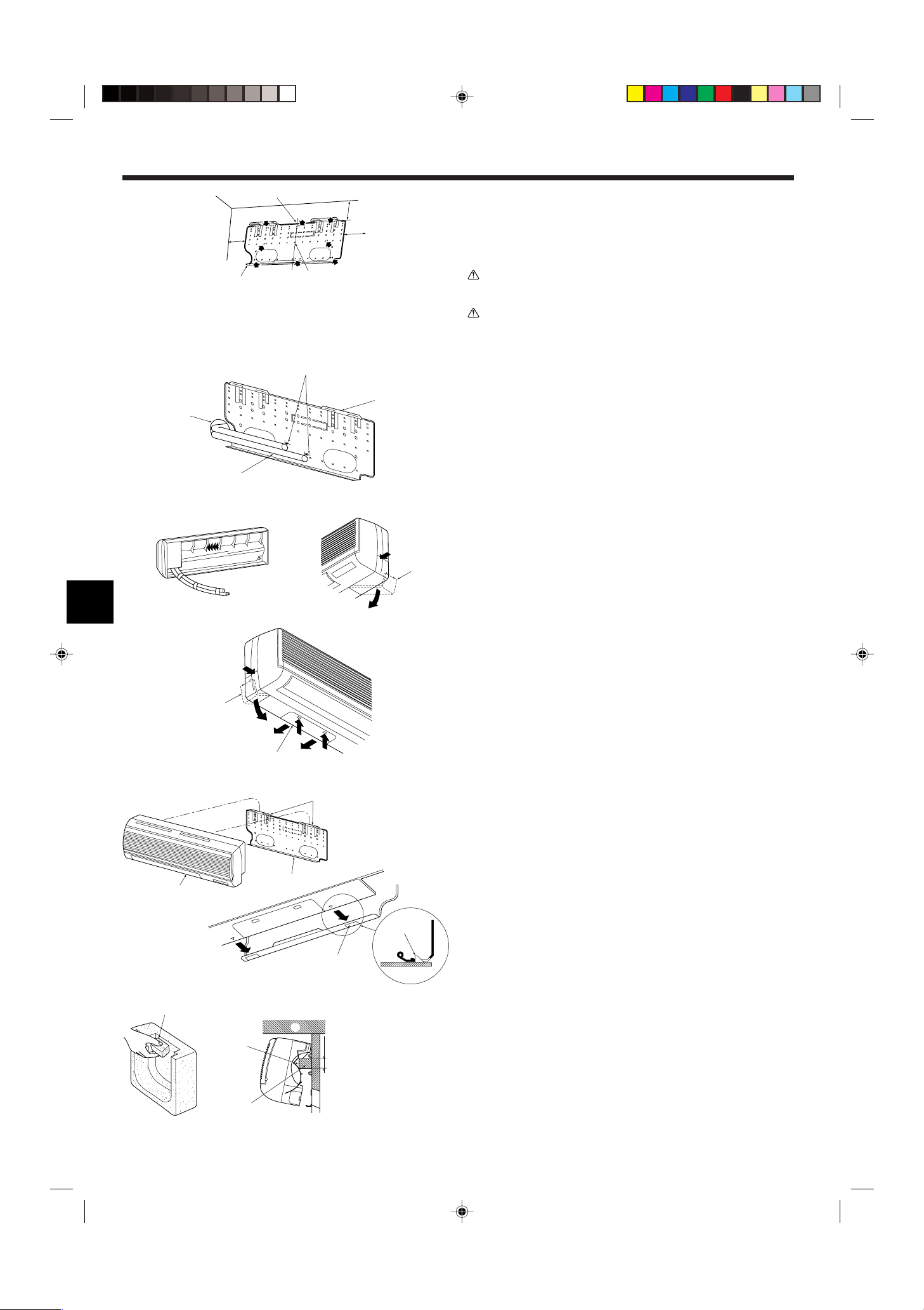
1
D
2
B
A
C
A
B
D
C
a
A
b
a
a
A
B
b
b
A
B
C
B
A
A
30~40
C
A
B
3. Installation de l’appareil intérieur
Fig. 3-4
Fig. 3-5
A Min. 140 mm
B Min. 300 mm
C Min. 55 mm
D Planche d’instal-
lation
3.2.3. Installation du support de montage mural
s L’appareil extérieur pesant près de 30 kg, choisir l’emplacement de montage en
tenant bien compte de ce fait. Si le mur ne semble pas être assez résistant, le renforcer avec des planches ou des poutres avant d’installer l’appareil.
s La structure de montage doit être attachée à ses deux extrémités et au centre, si
possible. Ne jamais la fixer à un seul endroit ou de manière asymétrique.
(Si possible, attacher la structure à tous les points indiqués par une flèche en
caractères gras.) (Fig. 3-4)
Avertissement:
Si possible, attacher la structure à tous les points marqués d’une flèche en caractè-
res gras.
Précaution:
• Le corps de l’appareil doit être monté à l’horizontale.
• Le fixer aux orifices marqunés d’un ▲.
1 Attachez un fil à l’orifice.
2 Ce niveau peut être obtenu facilement en attachant un poids au fil et en alignant le fil avec la
marque.
3.3. Lors de l’encastrement des tuyaux dans le mur
(Fig. 3-5)
• Les tuyaux se trouvent en bas à gauche.
• Lorsque le tuyau de réfrigérant, les lignes de connexion internes/externes des tuyaux
d’écoulement, etc. doivent être encastrés dans le mur à l’avance, les tuyaux qui sortent
etc, devront sans doute être coudés et vous devrez probablement modifier leur longueurs
pour les adapter à l’appareil.
• Utiliser les marques de la plaque de montage comme référence pour adapter la longueur
du tuyau de réfrigérant encastré.
• Pendant la construction, laisser une marge pour la longueur des tuyaux qui sortent etc.
A Plaque de montage
B Marques de référence pour les connexions évasées
C Orifice de pénétration
D Tuyauterie sur place
Fig. 3-6
Fig. 3-7
3.4. Préparation de l’appareil intérieur
Tuyautage arrière, à droite et en bas (Fig. 3-6)
1. Relier les tuyaux de réfrigérant et d’écoulement.
• Relier les tuyaux en appliquant du ruban de vinyle à trois endroits au moins. Ceci facili-
tera leur passage par le mur.
2. Retirer la boîte d’angle et dégager les orifices pré-coupés le cas échéant.
• Retirer la boîte d’angle en la poussant vers le bas b tout en appuyant sur sa partie
supérieure a.
A Boîte d’angle
B Couvercle du dessous
Tuyautage gauche et arrière gauche (Fig. 3-7)
1. Retirer le couvercle du dessous.
• Retirer le couvercle du dessous en le faisant glisser vers l’arrière de l’appareil b tout en
appuyant sur les deux points marqués par des têtes de flèches a.
2. Retirer la boîte d’angle et dégager les orifices prédécoupés le cas échéant.
3.5. Montage de l’appareil intérieur
1. Fixer la plaque de montage au mur.
2. Suspendre l’appareil intérieur sur les deux crochets placés dans la partie supérieure de
la plaque de montage.
Tuyautage arrière, à droite et en bas (Fig. 3-8)
3. Attacher l’appareil intérieur.
4. Après le raccordement des tuyaux, remettre la boîte d’angle en place (suivre les indica-
tions pour le démontage à l’envers).
A Orifice carré
B Crochets
Fig. 3-8
Tuyautage gauche et arrière gauche (Fig. 3-9)
(mm)
3. Découper une pièce de montage dans les matériaux d’emballage.
4. Soulever l’appareil intérieur vers soi comme l’indique la figure ci-dessous et glisser la
pièce de montage dans la plaque de montage, en utilisant les marques de position de la
pièce de montage comme référence.
5. Après le raccord des tuyaux et le câblage, remettre le couvercle du dessous en place et
retirer la pièce de montage; fixer l’appareil intérieur comme illustré sur la gauche.
6. Remettre la boîte d’angle en place.
A Pièce de montage
B Plafond
C Saillies
Fig. 3-9
30
 Loading...