

Mitsubishi PLA-RP_AA PLH-P_AAH, PMH-P_BA, PEAD-RP_EA PEHD-P_EAH, PEAD-RP_GA, PKA-RP_GAL PKH-P_GALH TECHNICAL MANUAL
...
SPLIT-TYPE, HEAT PUMP AIR CONDITIONERS
SPLIT-TYPE, AIR CONDITIONERS
July 2005
No. OCS02
TECHNICAL DATA BOOK
<Indoor unit>
[Model names]
<Outdoor unit>
[Model names]
PLA-RP·AA PLH-P·AAH
PMH-P·BA
PEAD-RP·EA PEHD-P·EAH
PEAD-RP·GA
PKA-RP·GAL PKH-P·GALH
PKA-RP·FAL PKH-P·FALH
PCA-RP·GA PCH-P·GAH
PCA-RP·HA
PSA-RP·GA PSH-P·GAH
PUH-P25/35/50/60/71/100VGAA
R407C
PUH-P35/50/60/71/100/125/140YGAA
PU-P35/50/60/71/100VGAA
PU-P35/50/60/71/100/125/140YGAA
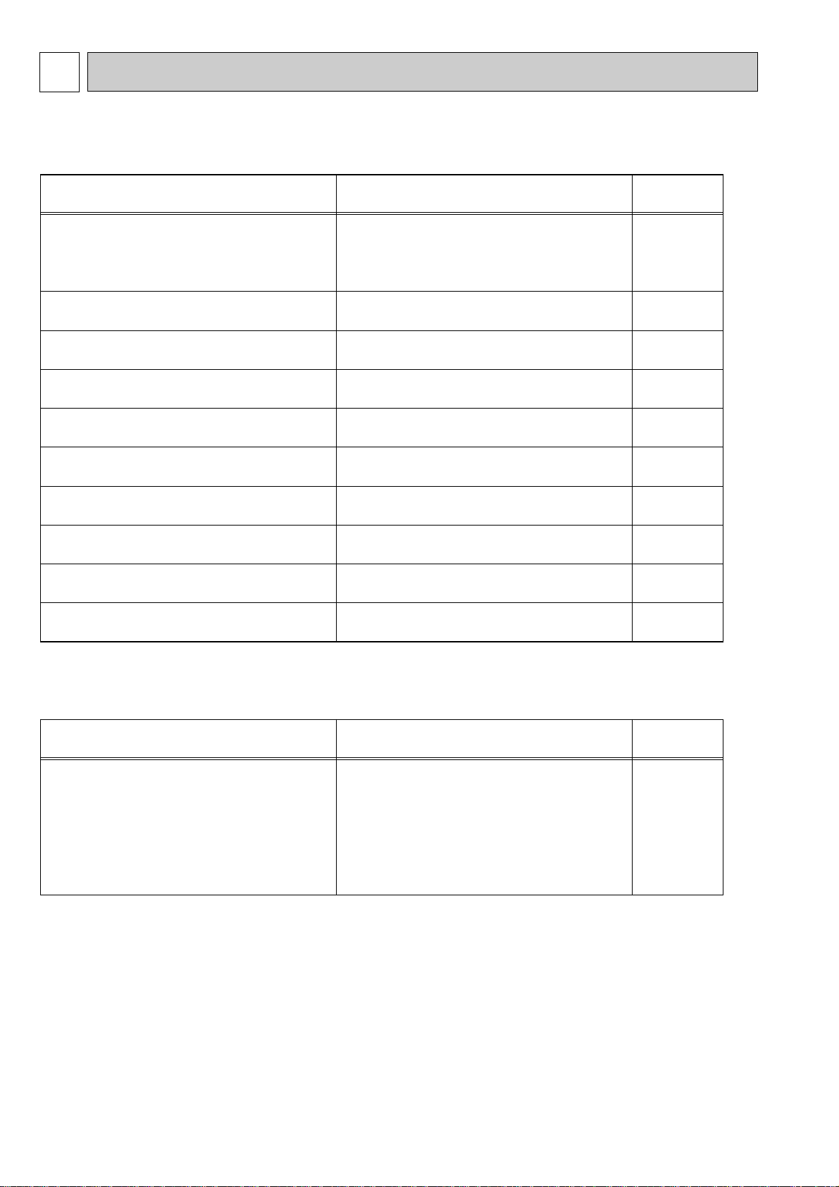
CONTENTS
1. REFERENCE SERVICE MANUAL·············································2
2. SPECIFICATIONS ······································································3
3. OUTLINES AND DIMENSIONS················································36
4. WIRING DIAGRAM···································································58
5. REFRIGERANT SYSTEM DIAGRAM ······································70
6. PERFORMANCE CURVES······················································73
7. CORRECTION FACTORS························································75
8. AIR FLOW DATA······································································76
9. NOISE CRITERION CURVES ··················································91
10. OPTIONAL PARTS ··································································105
kW Model
1-1. INDOOR UNIT
Model name Service Ref. Service
Manual No.
PLA-RP35/50/60/71AA PLA-RP35/50/60/71AA.UK OC335
PLA-RP100/125/140AA PLA-RP100/125/140AA.UK
PLH-P35/50/60/71AAH PLH-P35/50/60/71AAH.UK
PLH-P100/125/140AAH PLH-P100/125/140AAH.UK
PMH-P25/35/50BA PMH-P25/35/50BA OC333
PCA-RP50/60/71/100/125/140GA PCA-RP50/60/71/100/125/140GA OC328
PCH-P50/60/71/100/125/140GAH PCH-P50/60/71/100/125/140GAH
PCA-RP71/125HA PCA-RP71/125HA OC329
PKA-RP35/50GAL PKA-RP35/50GAL OC330
PKH-P35/50GALH PKH-P35/50GALH
PKA-RP60/71/100FAL PKA-RP60/71/100FAL OC331
PKH-P60/71/100FALH PKH-P60/71/100FALH
PSA-RP71/100/125/140GA PSA-RP71/100/125/140GA OC332
PSH-P71/100/125/140GAH PSH-P71/100/125/140GAH
PEAD-RP35/50/60/71EA PEAD-RP35/50/60/71EA.UK PEAD-RP100/125/140EA PEAD-RP100/125/140EA.UK
PEHD-P35/50/60/71EAH PEHD-P35/50/60/71EAH.UK PEHD-P100/125/140EAH PEHD-P100/125/140EAH.UK
PEAD-RP60/71/100GA PEAD-RP60/71/100GA.UK -
1-2. OUTDOOR UNIT
Model name Service Ref. Service
Manual No.
PUH-P25/35/50/60/71/100VGAA PUH-P25/35/50/60/71/100VGAA.UK OC336
PUH-P35/50/60/71YGAA PUH-P35/50/60/71YGAA.UK
PUH-P100/125/140YGAA PUH-P100/125/140YGAA.UK
PU-P35/50/60/71/100VGAA PU-P35/50/60/71/100VGAA.UK
PU-P35/50/60/71YGAA PU-P35/50/60/71YGAA.UK
PU-P100/125/140YGAA PU-P100/125/140YGAA.UK
1
REFERENCE SERVICE MANUAL
For information on service refer to the service manual as follows.
2
2
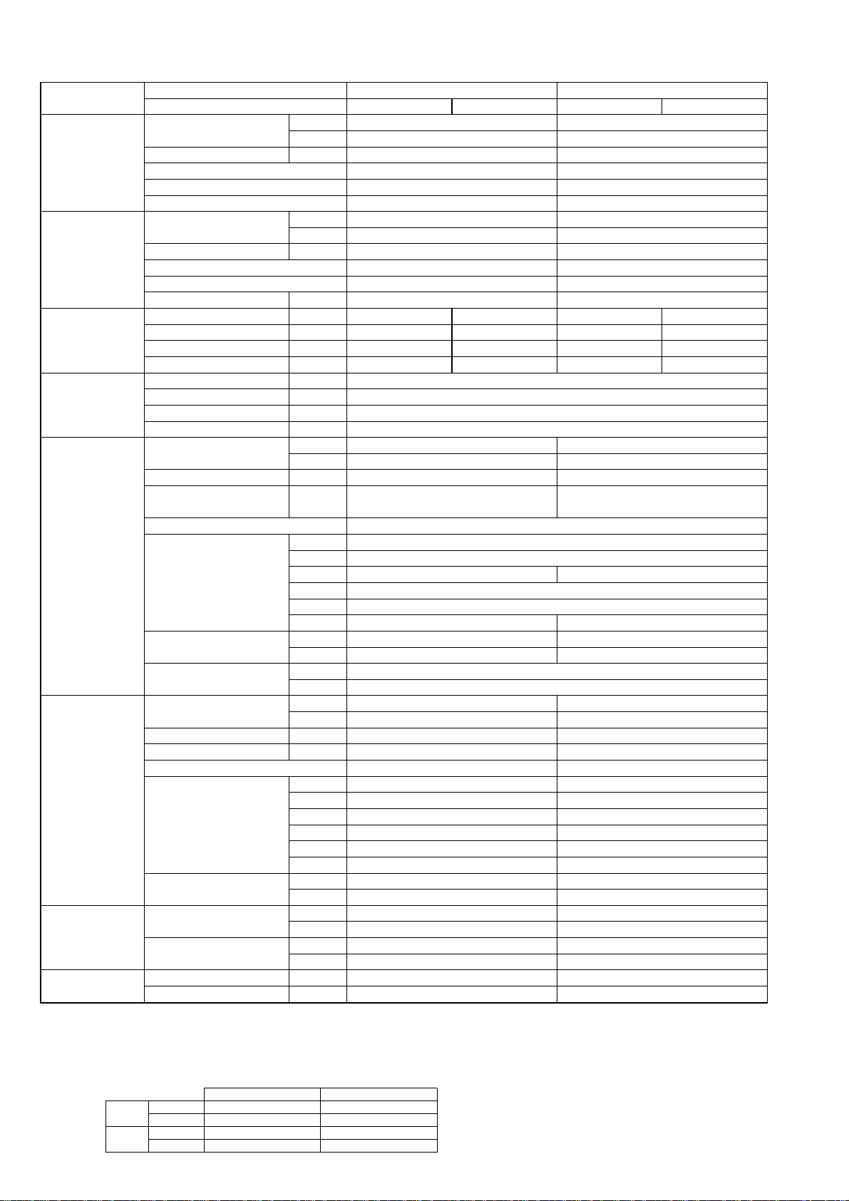
2-1. CEILING CASSETTE TYPE
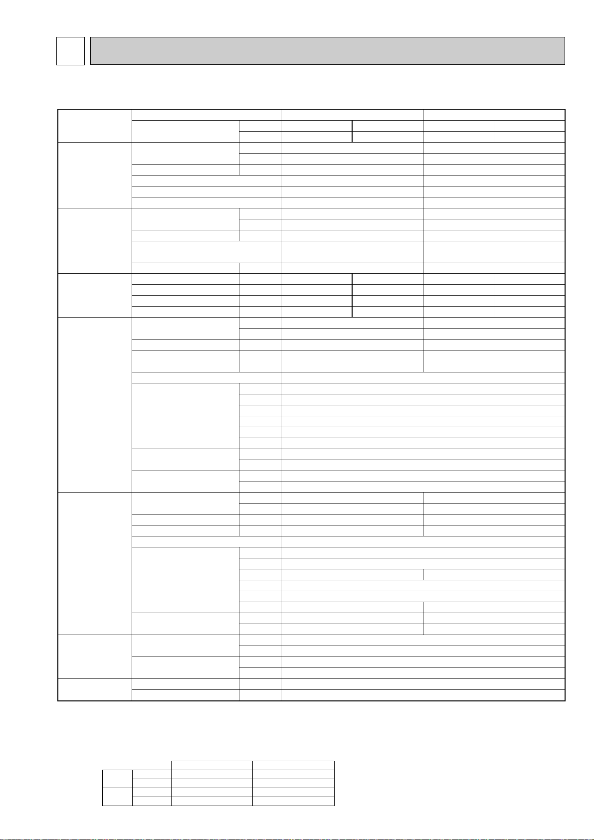
2-1-1.HEAT PUMP (without HEATER) AND COOLING ONLY TYPE
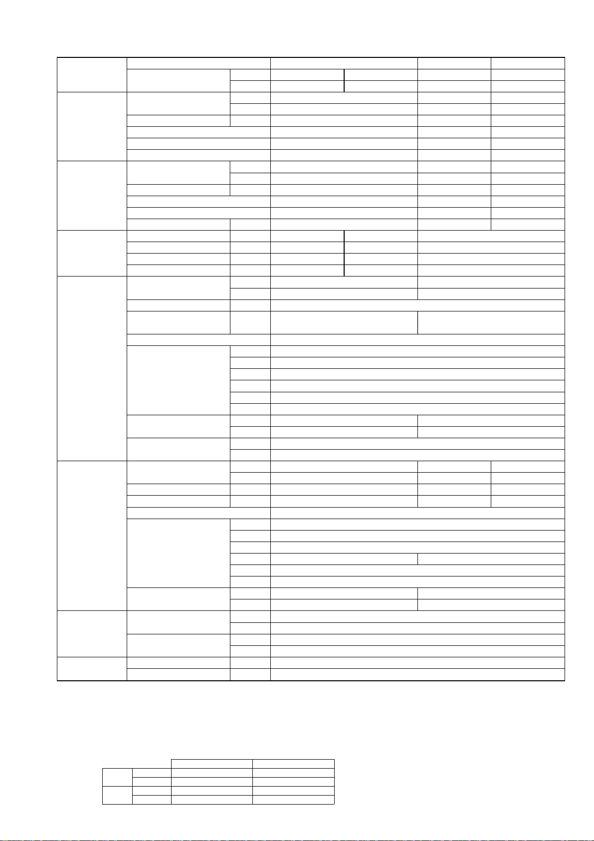
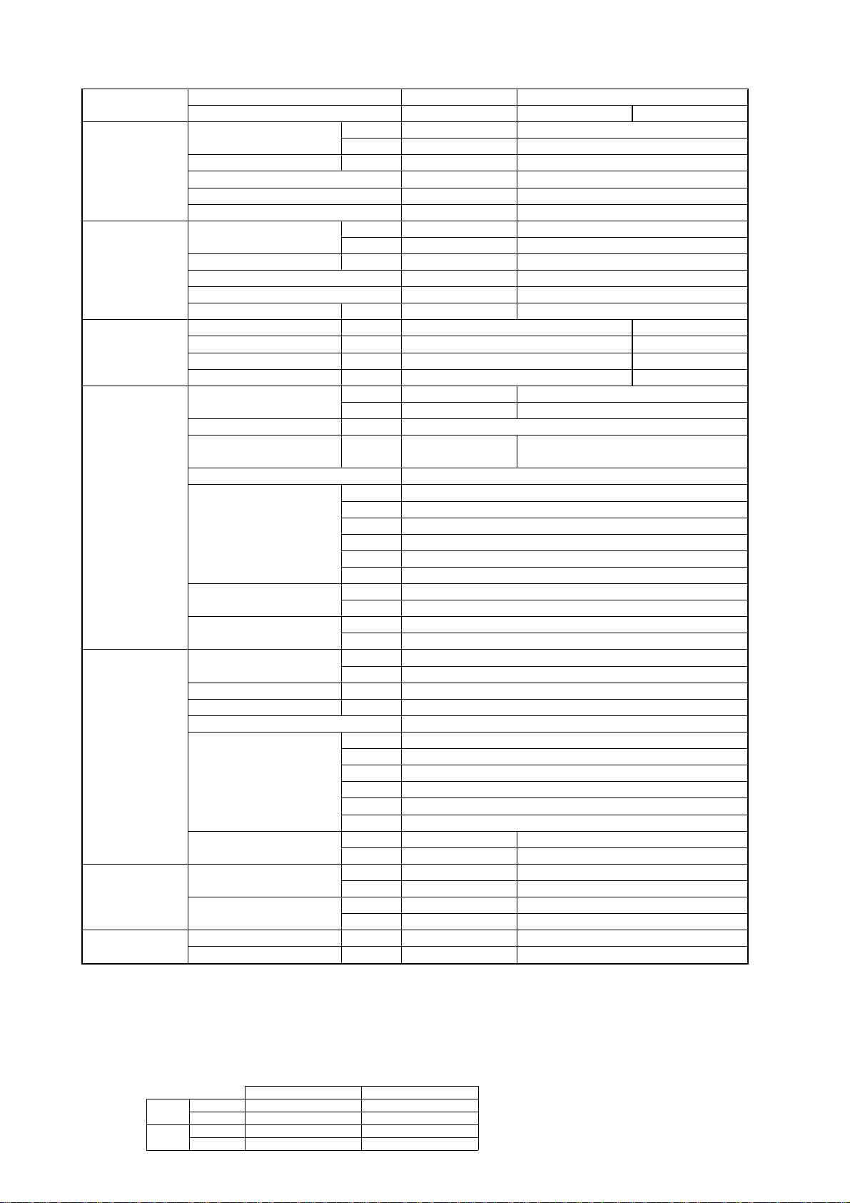
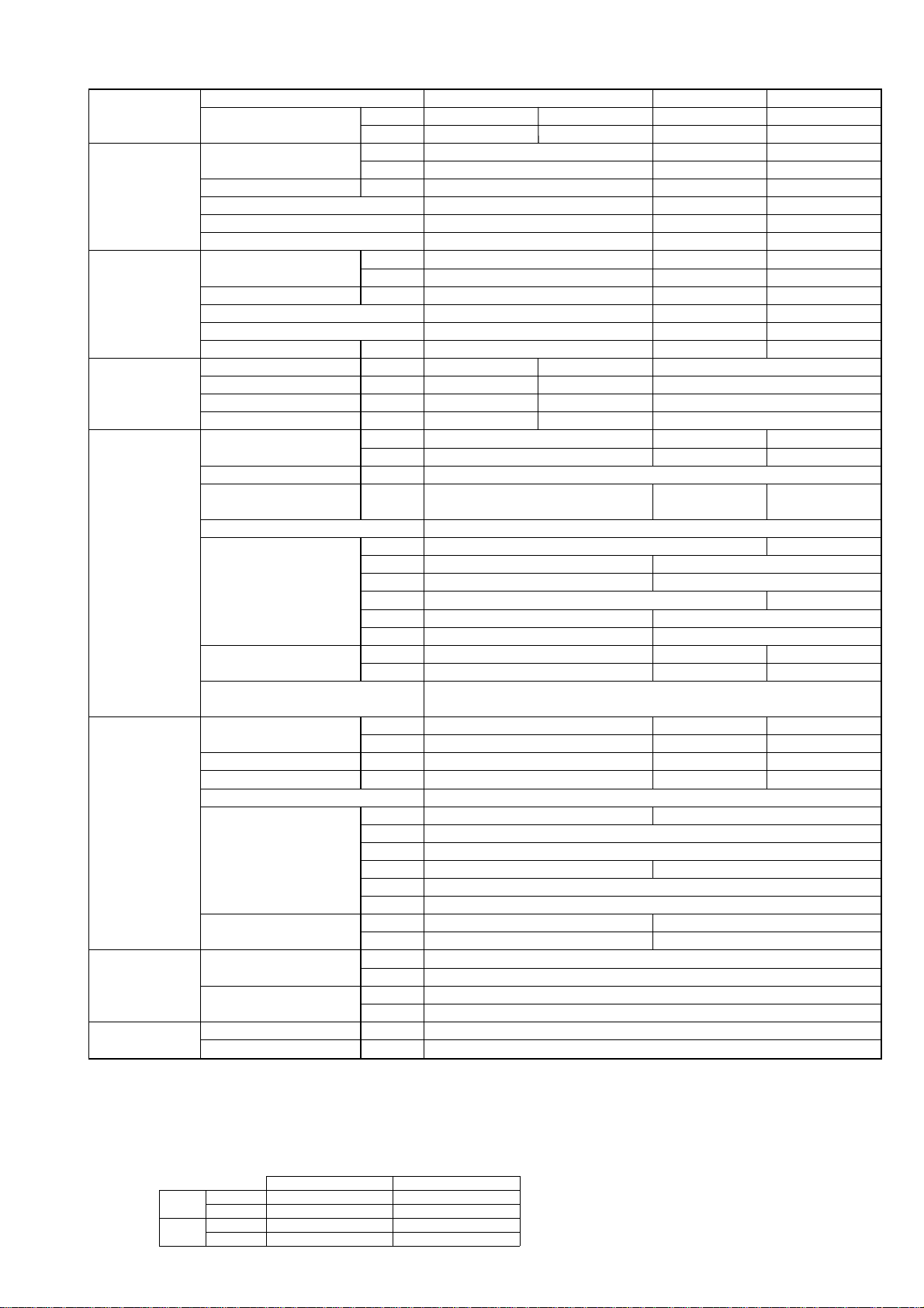
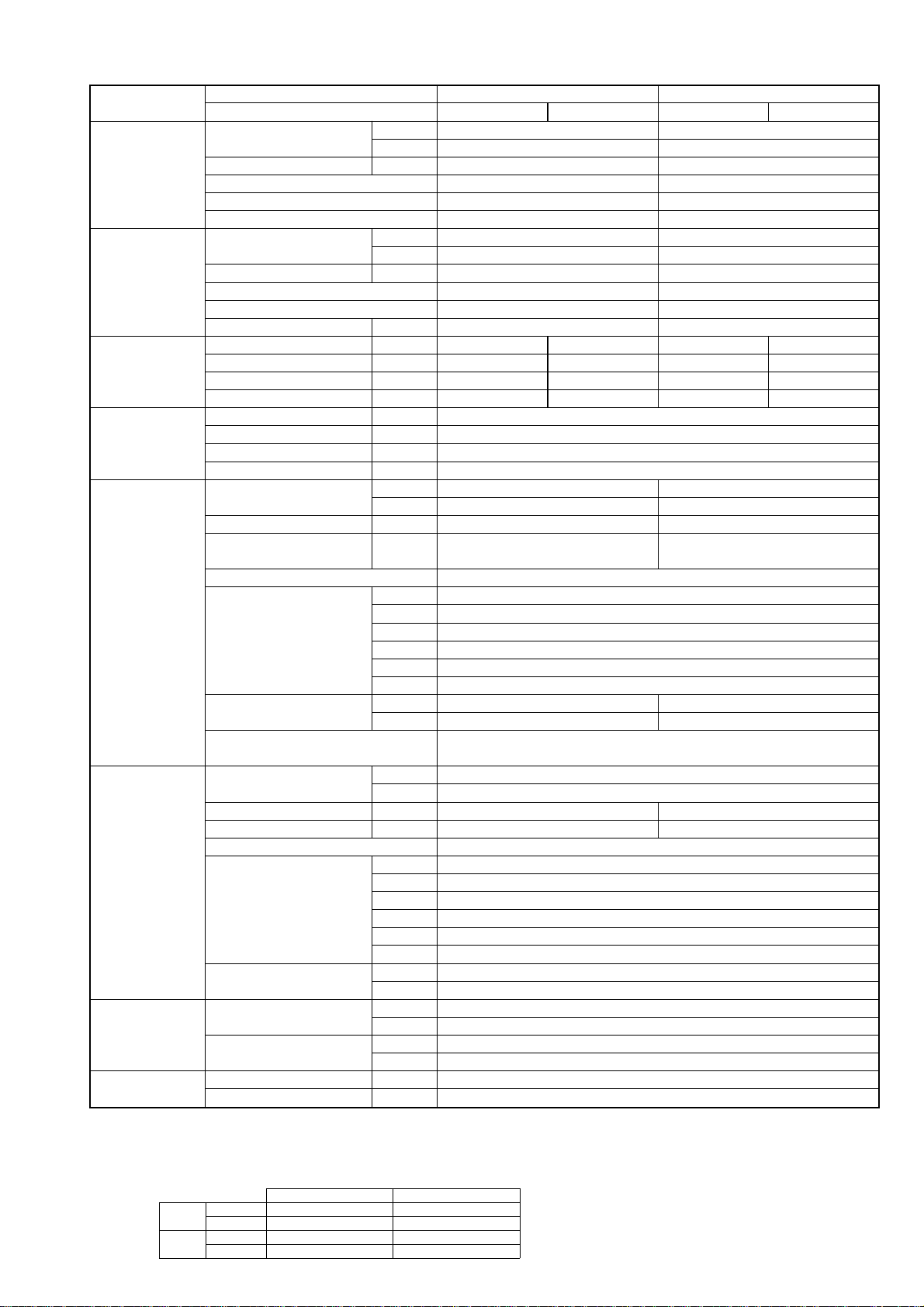
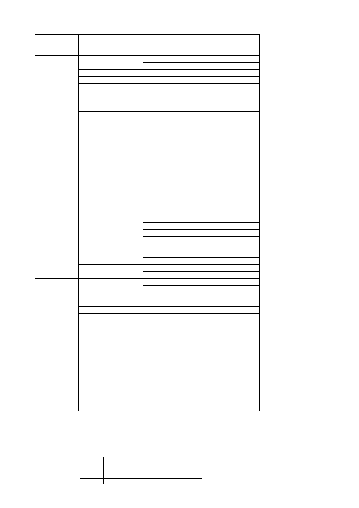
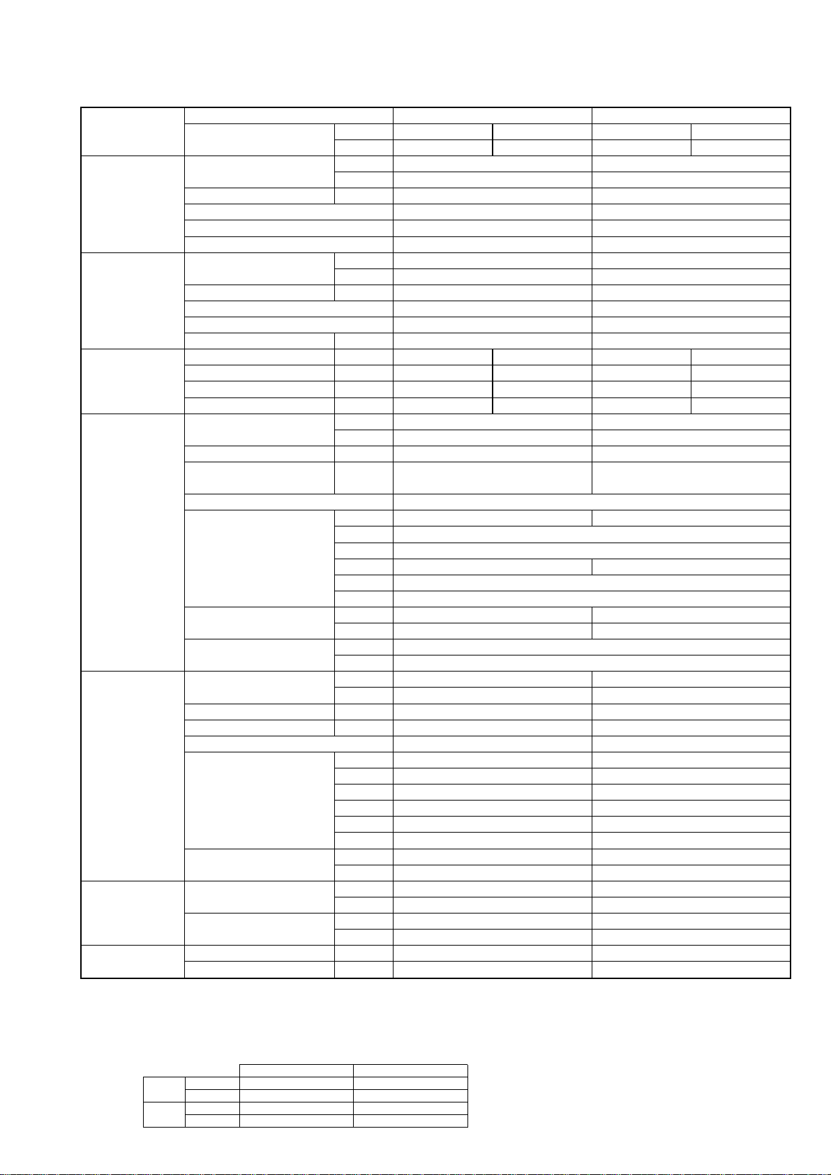
Model name Indoor unit PLA-RP35AA PLA-RP50AA
Outdoor unit H/P PUH-P35VGAA PUH-P35YGAA PUH-P50VGAA PUH-P50YGAA
C/O PU-P35VGAA PU-P35YGAA PU-P50VGAA PU-P50YGAA
Cooling Capacity Btu/h 15,400 19,100
kW 4.5 5.6
Total input kW 1.72 2.53
EER 2.62 2.21
Energy label class D F
SHF 0.75 0.82
Heating * Capacity Btu/h 16,900 21,700
kW 4.95 6.35
Total input kW 1.70 2.20
COP 2.91 2.89
Energy label class D D
Booster heater kW - -
Power supply Phase [ 1313
Cycle Hz 50 50 50 50
Voltage V 230 400 230 400
Breaker size A 16 16 25 16
Indoor unit Air flow CMM 11-12-13-14 14-15-16-18
(Low-Medium2-Medium1-High)
CFM 390-425-460-495 495-530-565-635
External pressure Pa 0 0
Sound level dB(A) 27-28-29-31 28-29-31-33
(Low-Medium2-Medium1-High)
External finish (Panel) White Munsell 0.70Y 8.59/0.97
Dimension W : mm 840 (950)
Unit (Panel) D : mm 840 (950)
H : mm 258 (30)
W : inch 33-1/16 (37-3/8)
D : inch 33-1/16 (37-3/8)
H : inch 10-3/16 (1-3/16)
Weight kg 24 (5)
Unit (Panel) lbs 53 (11)
Unit drain pipe I.D. mm 32
inch 1-1/4
Outdoor unit Air flow CMM 45 55
CFM 1,590 1,940
Sound level at cooling dB(A) 47 48
Sound level at heating * dB(A) 49 50
External finish Ivory Munsell 5Y 7/1
Dimension W : mm 900
D : mm 330+20
H : mm 650 855
W : inch 35-7/16
D : inch 13 + 3/4
H : inch 25-5/8 33-5/8
Weight kg 54 74
lbs 119 163
Refrigerant pipe Gas side O.D. mm 15.88
size inch 5/8
Liquid side O.D. mm 9.52
inch 3/8
Refrigerant pipe Height difference m Max. 40
length Length m Max. 40
* HEAT PUMP TYPE
NOTE: 1. Rating conditions (ISO T1)
Cooling Indoor : D.B. 27: (80˚F) W.B. 19: (66˚F) Outdoor : D.B. 35: (95˚F) W.B. 24: (75˚F)
Heating Indoor: D.B. 20: (68˚F) Outdoor : D.B. 7: (45˚F) W.B. 6: (43˚F)
Refrigerant piping length (one way) : 5m (16ft.)
2. Guaranteed operating range
Indoor Outdoor
Cooling
Upper limit
D.B. 35˚C, W.B. 22.5˚C
D.B. 46˚C
Lower limit
D.B. 19˚C, W.B. 15˚C D.B. -5˚C
Heating
Upper limit
D.B. 28˚C
D.B. 24˚C, W.B. 18˚C
Lower limit
D.B. 17˚C
D.B. -11˚C, W.B. -12˚C
4. Above data based on indicated voltage
Indoor unit Single phase 230V 50Hz
Single phase 230V 50Hz / 3phase 400V 50Hz
Outdoor unit
3. Guaranteed voltage
198~264V, 50Hz : Single phase
342~457V, 50Hz : 3phase
SPECIFICATIONS
3
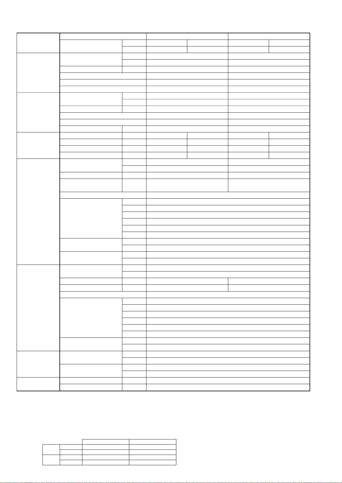
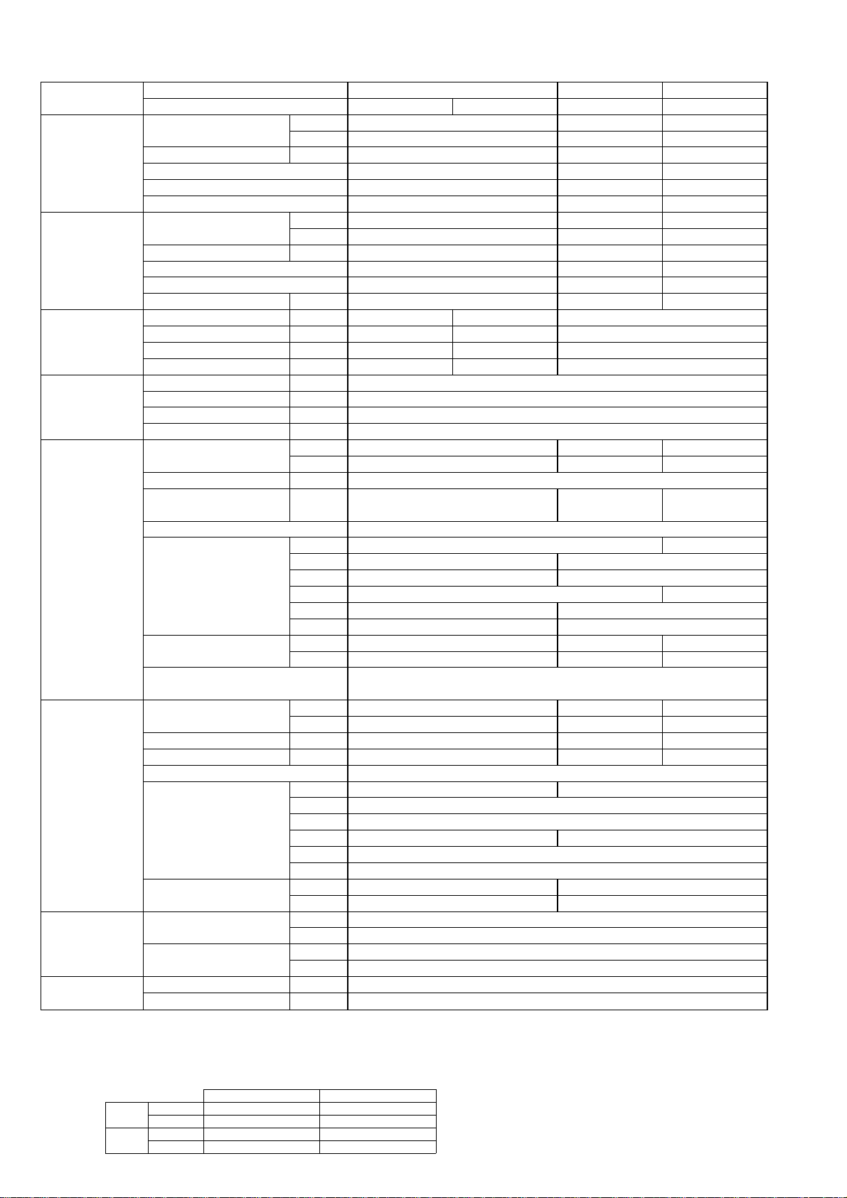
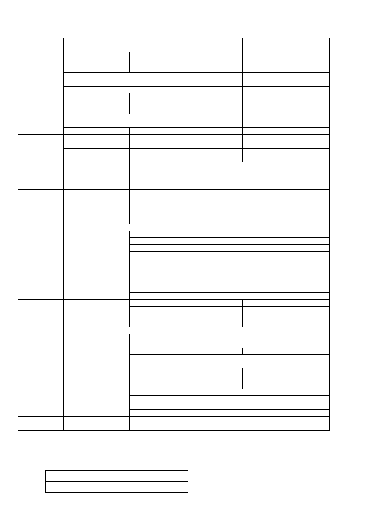
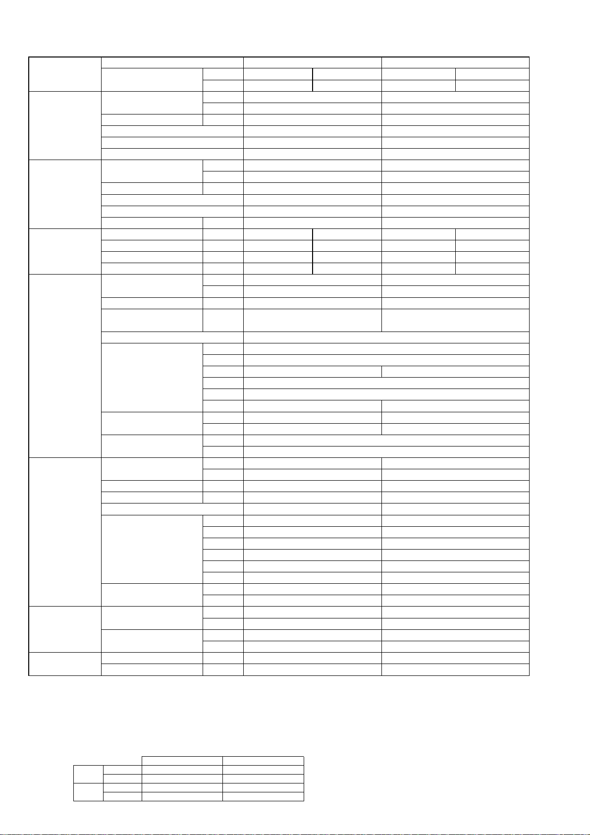
Model name Indoor unit PLA-RP60AA PLA-RP71AA
Outdoor unit H/P PUH-P60VGAA PUH-P60YGAA PUH-P71VGAA PUH-P71YGAA
C/O PU-P60VGAA PU-P60YGAA PU-P71VGAA PU-P71YGAA
Cooling Capacity Btu/h 22,900 26,300
kW 6.7 7.7
Total input kW 2.57 3.42
EER 2.61 2.25
Energy label class D F
SHF 0.72 0.74
Heating * Capacity Btu/h 24,900 31,400
kW 7.3 9.2
Total input kW 2.40 3.48
COP 3.04 2.64
Energy label class D E
Booster heater kW
-
--
Power supply Phase [ 1313
Cycle Hz 50 50 50 50
Voltage V 230 400 230 400
Breaker size A 25 16 32 16
Indoor unit Air flow CMM 14-15-16-18 15-16-18-20
(Low-Medium2-Medium1-High)
CFM 495-530-565-635 530-565-635-705
External pressure Pa 0 0
Sound level dB(A) 28-29-31-33 28-30-32-34
(Low-Medium2-Medium1-High)
External finish (Panel) White Munsell 0.70Y 8.59/0.97
Dimension W : mm 840 (950)
Unit (Panel) D : mm 840 (950)
H : mm 258 (30)
W : inch 33-1/16 (37-3/8)
D : inch 33-1/16 (37-3/8)
H : inch 10-3/16 (1-3/16)
Weight kg 24 (5)
Unit (Panel) lbs 53 (11)
Unit drain pipe I.D. mm 32
inch 1-1/4
Outdoor unit Air flow CMM 50
CFM 1,770
Sound level at cooling dB(A) 48 49
Sound level at heating* dB(A) 50 51
External finish Ivory Munsell 5Y 7/1
Dimension W : mm 900
D : mm 330+20
H : mm 855
W : inch 35-7/16
D : inch 13 + 3/4
H : inch 33-5/8
Weight kg 79
lbs 174
Refrigerant pipe Gas side O.D. mm 15.88
size inch 5/8
Liquid side O.D. mm 9.52
inch 3/8
Refrigerant pipe Height difference m Max. 50
length Length m Max. 50
* HEAT PUMP TYPE
NOTE: 1. Rating conditions (ISO T1)
Cooling Indoor : D.B. 27: (80˚F) W.B. 19: (66˚F) Outdoor : D.B. 35: (95˚F) W.B. 24: (75˚F)
Heating Indoor: D.B. 20: (68˚F) Outdoor : D.B. 7: (45˚F) W.B. 6: (43˚F)
Refrigerant piping length (one way) : 5m (16ft.)
2. Guaranteed operating range
Indoor Outdoor
Cooling
Upper limit
D.B. 35˚C, W.B. 22.5˚C
D.B. 46˚C
Lower limit
D.B. 19˚C, W.B. 15˚C D.B. -5˚C
Heating
Upper limit
D.B. 28˚C
D.B. 24˚C, W.B. 18˚C
Lower limit
D.B. 17˚C
D.B. -11˚C, W.B. -12˚C
4. Above data based on indicated voltage
Indoor unit Single phase 230V 50Hz
Single phase 230V 50Hz / 3phase 400V 50Hz
Outdoor unit
3. Guaranteed voltage
198~264V, 50Hz : Single phase
342~457V, 50Hz : 3phase
4
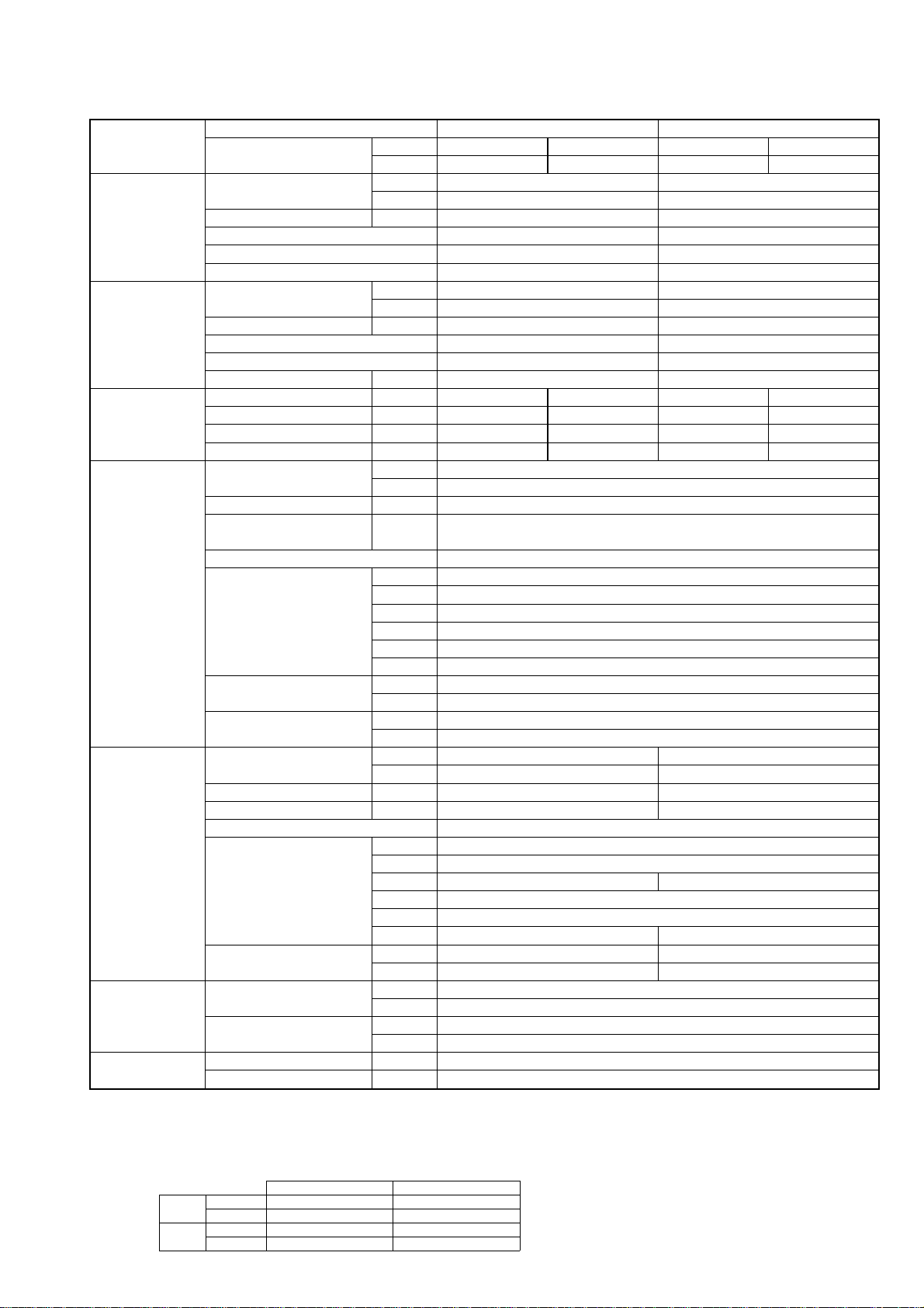
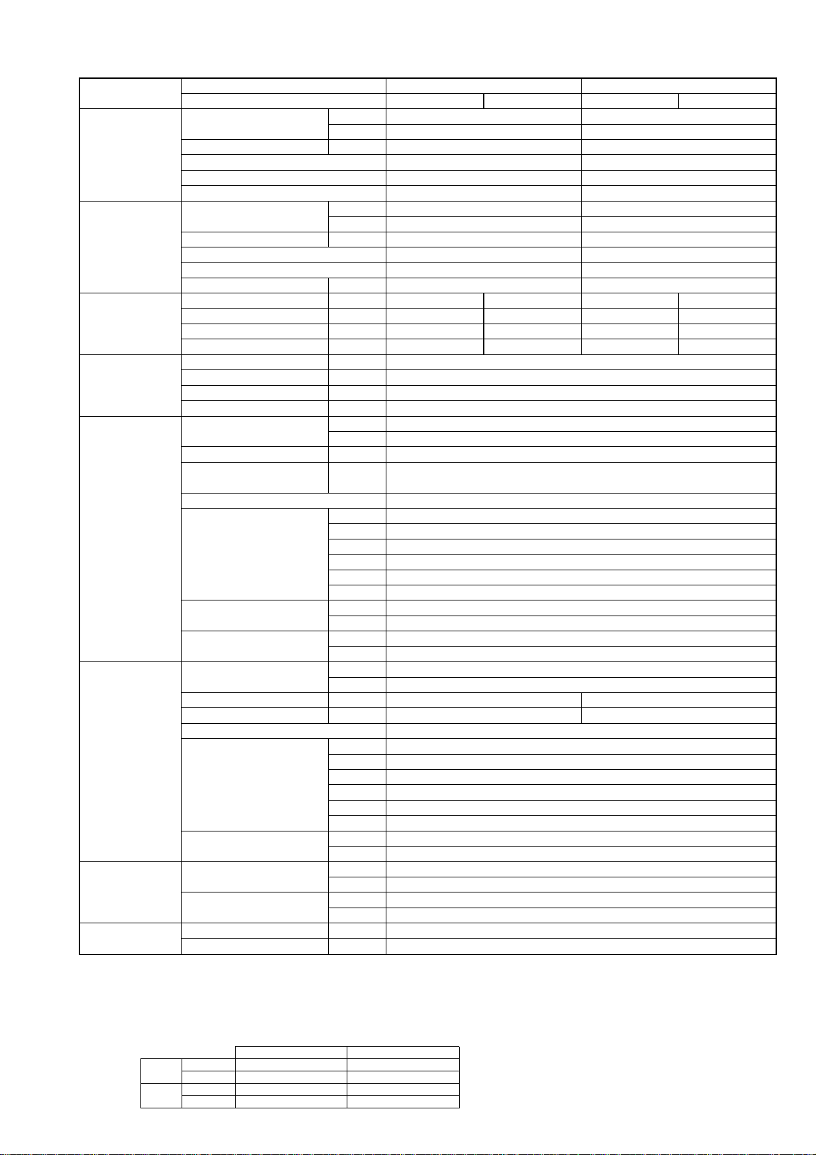
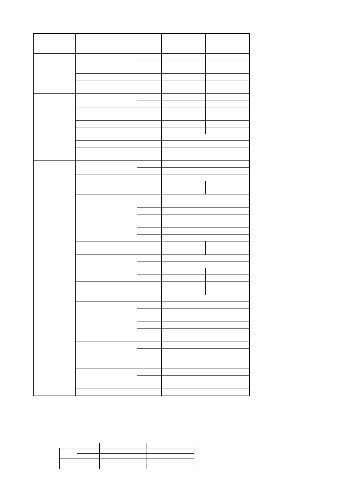
Model name Indoor unit PLA-RP100AA PLA-RP125AA PLA-RP140AA
Outdoor unit H/P PUH-P100VGAA PUH-P100YGAA PUH-P125YGAA PUH-P140YGAA
C/O PU-P100VGAA PU-P100YGAA PU-P125YGAA PU-P140YGAA
Cooling Capacity Btu/h 32,800 45,400 48,500
kW 9.6 13.3 14.2
Total input kW 3.68 5.09 5.90
EER 2.61 2.61 2.41
Energy label class D D E
SHF 0.78 0.72 0.69
Heating * Capacity Btu/h 35,800 53,200 58,000
kW 10.5 15.6 17.0
Total input kW 3.91 5.54 6.35
COP 2.69 2.82 2.68
Energy label class E D E
Booster heater kW - - -
Power supply Phase [ 13 3
Cycle Hz 50 50 50
Voltage V 230 400 400
Breaker size A 32 16 25
Indoor unit Air flow CMM 20-23-26-28 22-25-28-30
(Low-Medium2-Medium1-High)
CFM 705-810-920-990 775-880-990-1060
External pressure Pa 0
Sound level dB(A) 33-36-39-41 37-40-43-45
(Low-Medium2-Medium1-High)
External finish (Panel) White Munsell 0.70Y 8.59/0.97
Dimension W : mm 840 (950)
Unit (Panel) D : mm 840 (950)
H : mm 298 (30)
W : inch 33-1/16 (37-3/8)
D : inch 33-1/16 (37-3/8)
H : inch 11-3/4 (1-3/16)
Weight kg 30 (5) 32(5)
Unit (Panel) lbs 66 (11) 71(11)
Unit drain pipe I.D. mm 32
inch 1-1/4
Outdoor unit Air flow CMM 85 95 100
CFM 3,000 3,360 3,530
Sound level at cooling dB(A) 51 55 57
Sound level at heating* dB(A) 53 56 58
External finish Ivory Munsell 5Y 7/1
Dimension W : mm 900 1050
D : mm 330+20
H : mm 1260
W : inch 35-7/16 41-5/16
D : inch 13 + 3/4
H : inch 49-5/8
Weight kg 97 125
lbs 214 276
Refrigerant pipe Gas side O.D. mm 19.05
size inch 3/4
Liquid side O.D. mm 9.52
inch 3/8
Refrigerant pipe Height difference m Max. 50
length Length m Max. 50
* HEAT PUMP TYPE
NOTE: 1. Rating conditions (ISO T1)
Cooling Indoor : D.B. 27: (80˚F) W.B. 19: (66˚F) Outdoor : D.B. 35: (95˚F) W.B. 24: (75˚F)
Heating Indoor: D.B. 20: (68˚F) Outdoor : D.B. 7: (45˚F) W.B. 6: (43˚F)
Refrigerant piping length (one way) : 5m (16ft.)
2. Guaranteed operating range
Indoor Outdoor
Cooling
Upper limit
D.B. 35˚C, W.B. 22.5˚C
D.B. 46˚C
Lower limit
D.B. 19˚C, W.B. 15˚C D.B. -5˚C
Heating
Upper limit
D.B. 28˚C
D.B. 24˚C, W.B. 18˚C
Lower limit
D.B. 17˚C
D.B. -11˚C, W.B. -12˚C
4. Above data based on indicated voltage
Indoor unit Single phase 230V 50Hz
Single phase 230V 50Hz / 3phase 400V 50Hz
Outdoor unit
3. Guaranteed voltage
198~264V, 50Hz : Single phase
342~457V, 50Hz : 3phase
5
2-1-2.HEAT PUMP (with HEATER) TYPE
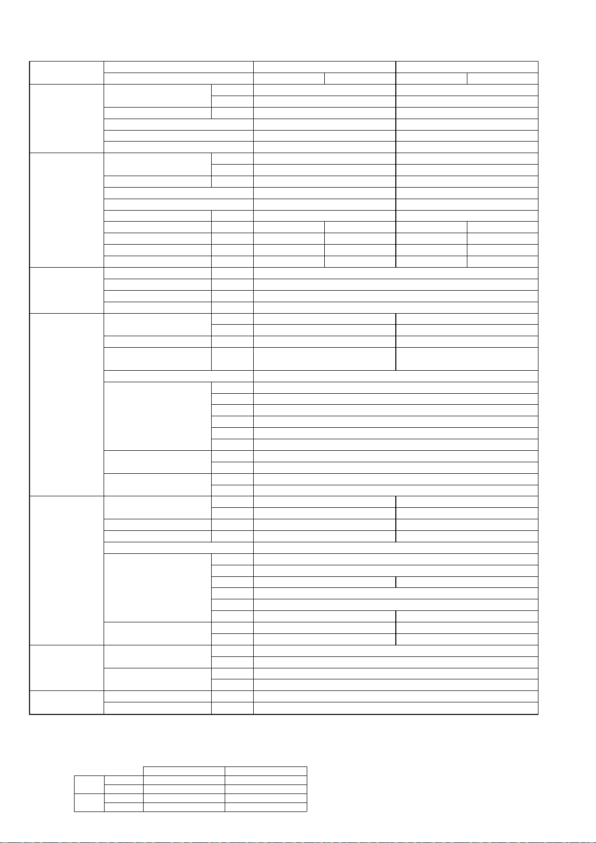
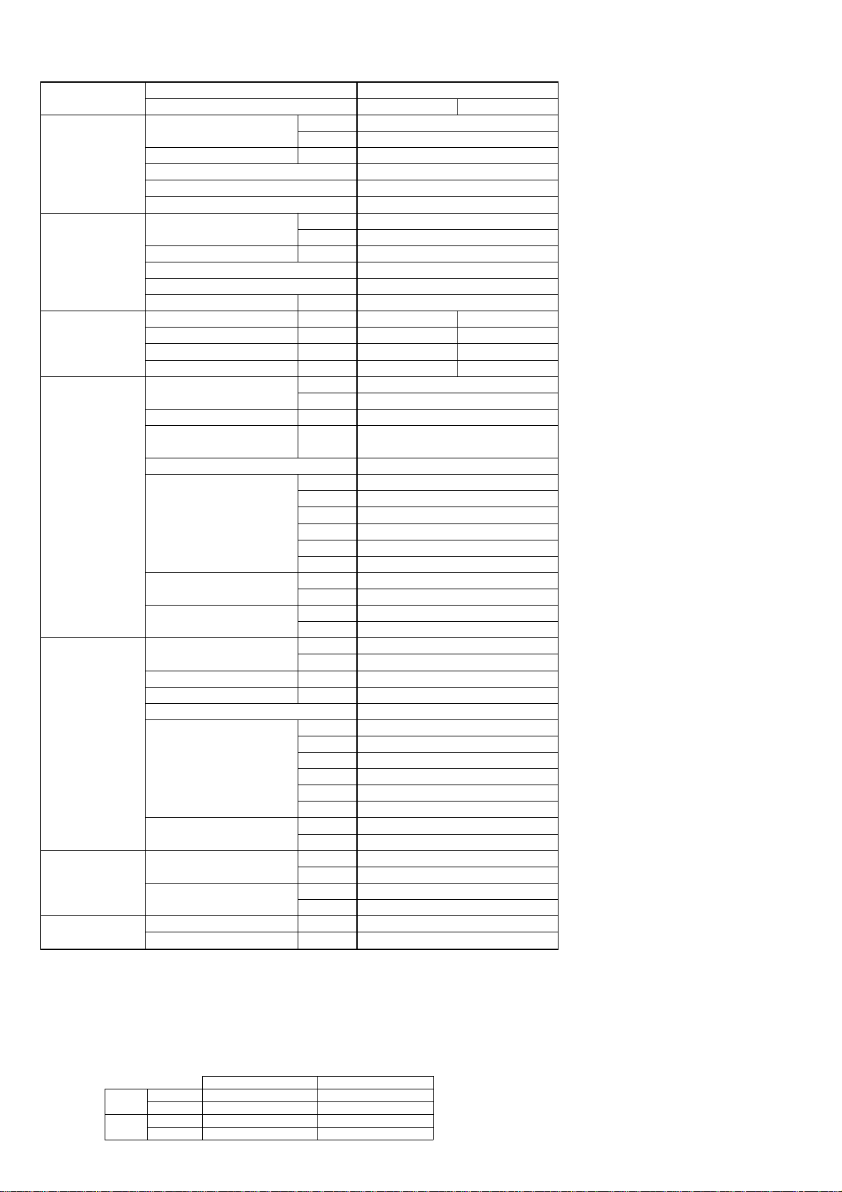
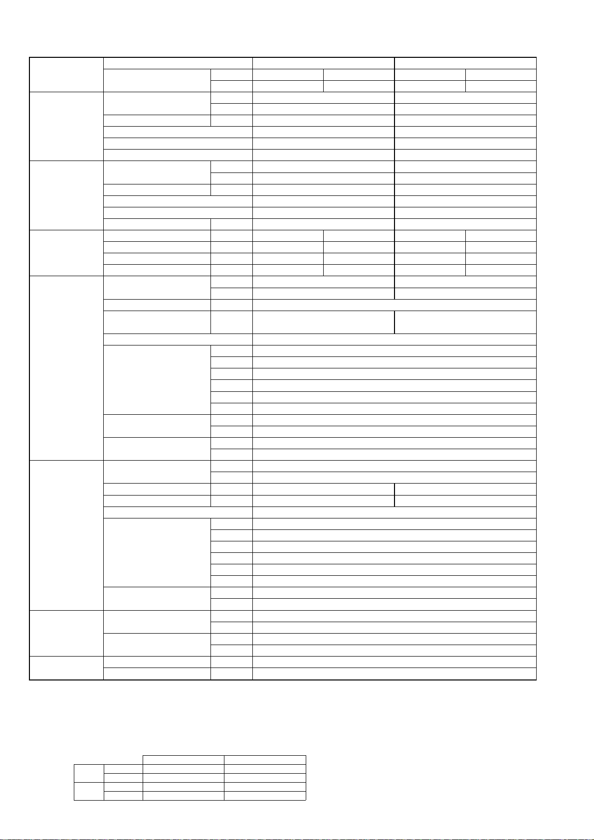
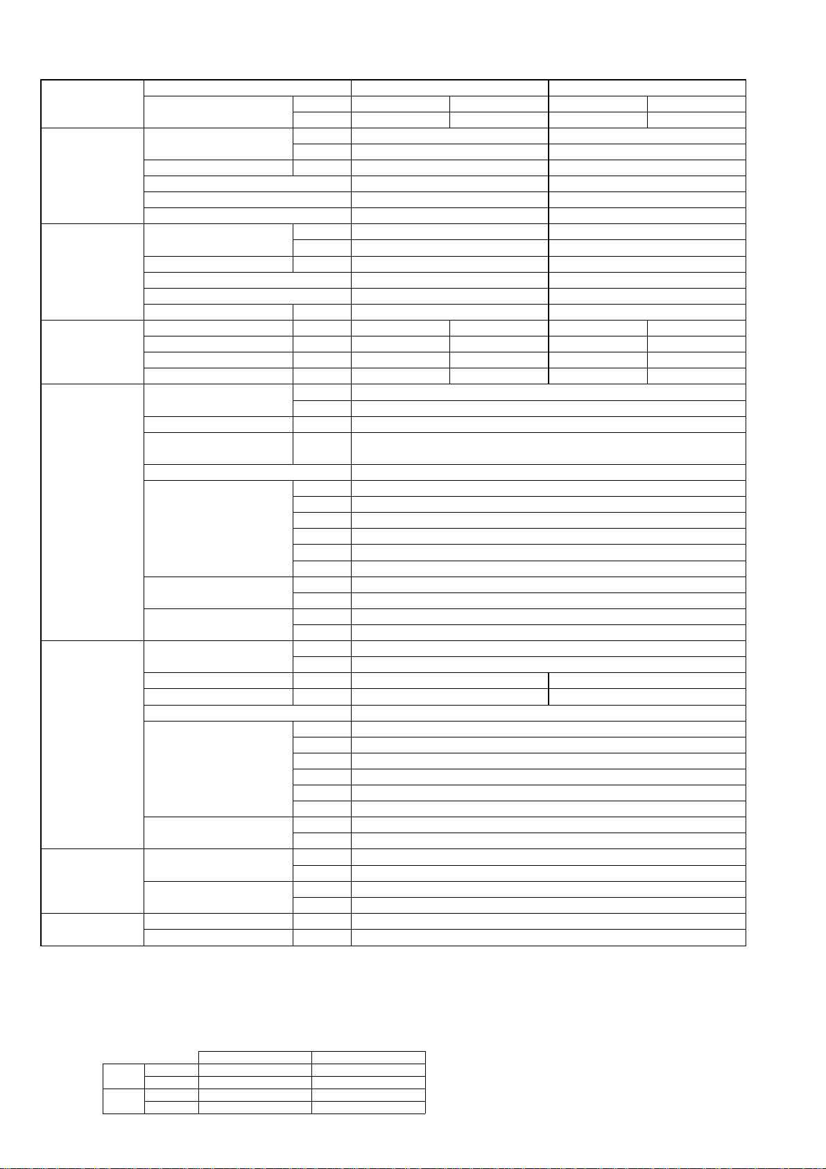
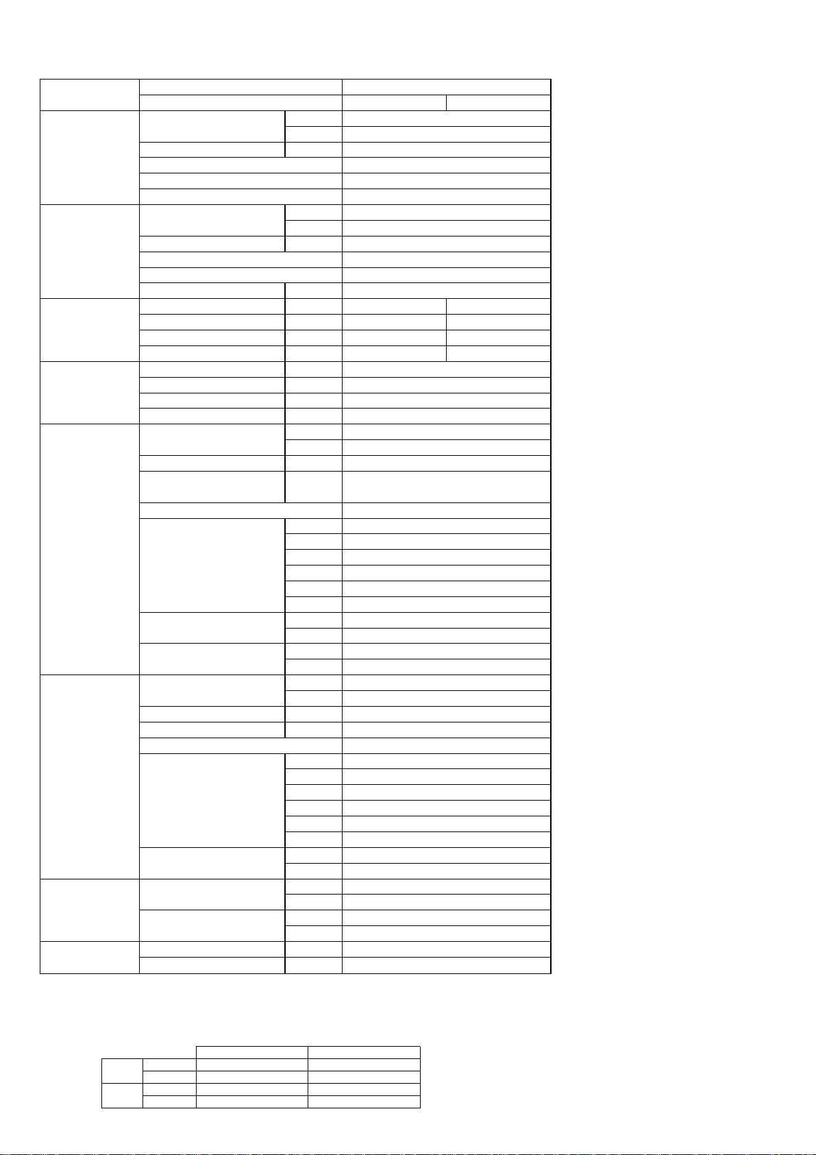
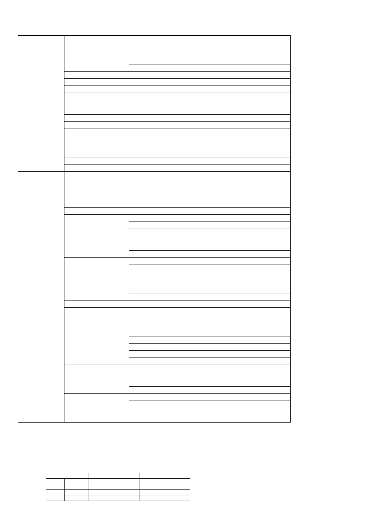
Model name Indoor unit PLH-P35AAH PLH-P50AAH
Outdoor unit PUH-P35VGAA PUH-P35YGAA PUH-P50VGAA PUH-P50YGAA
Cooling Capacity Btu/h 15,400 19,100
kW 4.5 5.6
Total input kW 1.72 2.53
EER 2.62 2.21
Energy label class D F
SHF 0.75 0.82
Heating Capacity Btu/h 16,900 21,700
kW 4.95 6.35
Total input kW 1.70 2.20
COP 2.91 2.89
Energy label class D D
Booster heater kW 1.29 1.29
Power supply Phase [ 1313
Cycle Hz 50 50 50 50
Voltage V 230 400 230 400
Breaker size A 16 16 25 16
Power supply Phase [ 1
for heater Cycle Hz 50
Voltage V 230
Breaker size A 16
Indoor unit Air flow CMM 11-12-13-14 14-15-16-18
(Low-Medium2-Medium1-High)
CFM 390-425-460-495 495-530-565-635
External pressure Pa 0 0
Sound level dB(A) 27-28-29-31 28-29-31-33
(Low-Medium2-Medium1-High)
External finish (Panel) White Munsell 0.70Y 8.59/0.97
Dimension W : mm 840 (950)
Unit (Panel) D : mm 840 (950)
H : mm 258 (30)
W : inch 33-1/16 (37-3/8)
D : inch 33-1/16 (37-3/8)
H : inch 10-3/16 (1-3/16)
Weight kg 26(5)
Unit (Panel) lbs 57 (11)
Unit drain pipe I.D. mm 32
inch 1-1/4
Outdoor unit Air flow CMM 45 55
CFM 1,590 1,940
Sound level at cooling dB(A) 47 48
Sound level at heating dB(A) 49 50
External finish Ivory Munsell 5Y 7/1
Dimension W : mm 900
D : mm 330+20
H : mm 650 855
W : inch 35-7/16
D : inch 13 + 3/4
H : inch 25-5/8 33-5/8
Weight kg 54 74
lbs 119 163
Refrigerant pipe Gas side O.D. mm 15.88
size inch 5/8
Liquid side O.D. mm 9.52
inch 3/8
Refrigerant pipe Height difference m Max. 40
length Length m Max. 40
NOTE: 1. Rating conditions (ISO T1)
Cooling Indoor : D.B. 27: (80˚F) W.B. 19: (66˚F) Outdoor : D.B. 35: (95˚F) W.B. 24: (75˚F)
Heating Indoor: D.B. 20: (68˚F) Outdoor : D.B. 7: (45˚F) W.B. 6: (43˚F)
Refrigerant piping length (one way) : 5m (16ft.)
2. Guaranteed operating range
Indoor Outdoor
Cooling
Upper limit
D.B. 35˚C, W.B. 22.5˚C
D.B. 46˚C
Lower limit
D.B. 19˚C, W.B. 15˚C D.B. -5˚C
Heating
Upper limit
D.B. 28˚C
D.B. 24˚C, W.B. 18˚C
Lower limit
D.B. 17˚C
D.B. -11˚C, W.B. -12˚C
4. Above data based on indicated voltage
Indoor unit Single phase 230V 50Hz
Single phase 230V 50Hz / 3phase 400V 50Hz
Outdoor unit
3. Guaranteed voltage
198~264V, 50Hz : Single phase
342~457V, 50Hz : 3phase
6
NOTE: 1. Rating conditions (ISO T1)
Cooling Indoor : D.B. 27: (80˚F) W.B. 19: (66˚F) Outdoor : D.B. 35: (95˚F) W.B. 24: (75˚F)
Heating Indoor: D.B. 20: (68˚F) Outdoor : D.B. 7: (45˚F) W.B. 6: (43˚F)
Refrigerant piping length (one way) : 5m (16ft.)
2. Guaranteed operating range
Indoor Outdoor
Cooling
Upper limit
D.B. 35˚C, W.B. 22.5˚C
D.B. 46˚C
Lower limit
D.B. 19˚C, W.B. 15˚C D.B. -5˚C
Heating
Upper limit
D.B. 28˚C
D.B. 24˚C, W.B. 18˚C
Lower limit
D.B. 17˚C
D.B. -11˚C, W.B. -12˚C
4. Above data based on indicated voltage
Indoor unit Single phase 230V 50Hz
Single phase 230V 50Hz / 3phase 400V 50Hz
Outdoor unit
3. Guaranteed voltage
198~264V, 50Hz : Single phase
342~457V, 50Hz : 3phase
Model name Indoor unit PLH-P60AAH PLH-P71AAH
Outdoor unit PUH-P60VGAA PUH-P60YGAA PUH-P71VGAA PUH-P71YGAA
Cooling Capacity Btu/h 22,900 26,300
kW 6.7 7.7
Total input kW 2.57 3.42
EER 2.61 2.25
Energy label class D F
SHF 0.72 0.74
Heating Capacity Btu/h 24,900 31,400
kW 7.3 9.2
Total input kW 2.40 3.48
COP 3.04 2.64
Energy label class D E
Booster heater kW 1.93 1.93
Power supply Phase [ 1313
Cycle Hz 50 50 50 50
Voltage V 230 400 230 400
Breaker size A 25 16 32 16
Power supply Phase [ 1
for heater Cycle Hz 50
Voltage V 230
Breaker size A 16
Indoor unit Air flow CMM 14-15-16-18 15-16-18-20
(Low-Medium2-Medium1-High)
CFM 495-530-565-635 530-565-635-705
External pressure Pa 0 0
Sound level dB(A) 28-29-31-33 28-30-32-34
(Low-Medium2-Medium1-High)
External finish (Panel) White Munsell 0.70Y 8.59/0.97
Dimension W : mm 840 (950)
Unit (Panel) D : mm 840 (950)
H : mm 258 (30)
W : inch 33-1/16 (37-3/8)
D : inch 33-1/16 (37-3/8)
H : inch 10-3/16 (1-3/16)
Weight kg 26(5)
Unit (Panel) lbs 57 (11)
Unit drain pipe I.D. mm 32
inch 1-1/4
Outdoor unit Air flow CMM 50
CFM 1,770
Sound level at cooling dB(A) 48 49
Sound level at heating dB(A) 50 51
External finish Ivory Munsell 5Y 7/1
Dimension W : mm 900
D : mm 330+20
H : mm 855
W : inch 35-7/16
D : inch 13 + 3/4
H : inch 33-5/8
Weight kg 79
lbs 174
Refrigerant pipe Gas side O.D. mm 15.88
size inch 5/8
Liquid side O.D. mm 9.52
inch 3/8
Refrigerant pipe Height difference m Max. 50
length Length m Max. 50
7
Model name Indoor unit PLH-P100AAH PLH-P125AAH PLH-P140AAH
Outdoor unit PUH-P100VGAA PUH-P100YGAA PUH-P125YGAA PUH-P140YGAA
Cooling Capacity Btu/h 32,800 45,400 48,500
kW 9.6 13.3 14.2
Total input kW 3.68 5.09 5.90
EER 2.61 2.61 2.41
Energy label class D D E
SHF 0.78 0.72 0.69
Heating Capacity Btu/h 35,800 53,200 58,000
kW 10.5 15.6 17.0
Total input kW 3.91 5.54 6.35
COP 2.69 2.82 2.68
Energy label class E D E
Booster heater kW 2.39 2.76 2.76
Power supply Phase [ 13 3
Cycle Hz 50 50 50
Voltage V 230 400 400
Breaker size A 32 16 25
Power supply Phase [ 1
for heater Cycle Hz 50
Voltage V 230
Breaker size A 16
Indoor unit Air flow CMM 20-23-26-28 22-25-28-30
(Low-Medium2-Medium1-High)
CFM 705-810-920-990 775-880-990-1060
External pressure Pa 0
Sound level dB(A) 33-36-39-41 37-40-43-45
(Low-Medium2-Medium1-High)
External finish (Panel) White Munsell 0.70Y 8.59/0.97
Dimension W : mm 840 (950)
Unit (Panel) D : mm 840 (950)
H : mm 298 (30)
W : inch 33-1/16 (37-3/8)
D : inch 33-1/16 (37-3/8)
H : inch 11-3/4 (1-3/16)
Weight kg 32 (5) 34(5)
Unit (Panel) lbs 71 (11) 75(11)
Unit drain pipe I.D. mm 32
inch 1-1/4
Outdoor unit Air flow CMM 85 95 100
CFM 3,000 3,360 3,530
Sound level at cooling dB(A) 51 55 57
Sound level at heating dB(A) 53 56 58
External finish Ivory Munsell 5Y 7/1
Dimension W : mm 900 1050
D : mm 330+20
H : mm 1260
W : inch 35-7/16 41-5/16
D : inch 13 + 3/4
H : inch 49-5/8
Weight kg 97 125
lbs 214 276
Refrigerant pipe Gas side O.D. mm 19.05
size inch 3/4
Liquid side O.D. mm 9.52
inch 3/8
Refrigerant pipe Height difference m Max. 50
length Length m Max. 50
NOTE: 1. Rating conditions (ISO T1)
Cooling Indoor : D.B. 27: (80˚F) W.B. 19: (66˚F) Outdoor : D.B. 35: (95˚F) W.B. 24: (75˚F)
Heating Indoor: D.B. 20: (68˚F) Outdoor : D.B. 7: (45˚F) W.B. 6: (43˚F)
Refrigerant piping length (one way) : 5m (16ft.)
2. Guaranteed operating range
Indoor Outdoor
Cooling
Upper limit
D.B. 35˚C, W.B. 22.5˚C
D.B. 46˚C
Lower limit
D.B. 19˚C, W.B. 15˚C D.B. -5˚C
Heating
Upper limit
D.B. 28˚C
D.B. 24˚C, W.B. 18˚C
Lower limit
D.B. 17˚C
D.B. -11˚C, W.B. -12˚C
4. Above data based on indicated voltage
Indoor unit Single phase 230V 50Hz
Single phase 230V 50Hz / 3phase 400V 50Hz
Outdoor unit
3. Guaranteed voltage
198~264V, 50Hz : Single phase
342~457V, 50Hz : 3phase
8
2-1-3.HEAT PUMP (without HEATER) TYPE (PMH series)
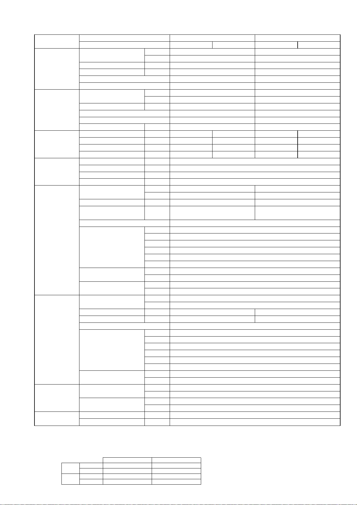
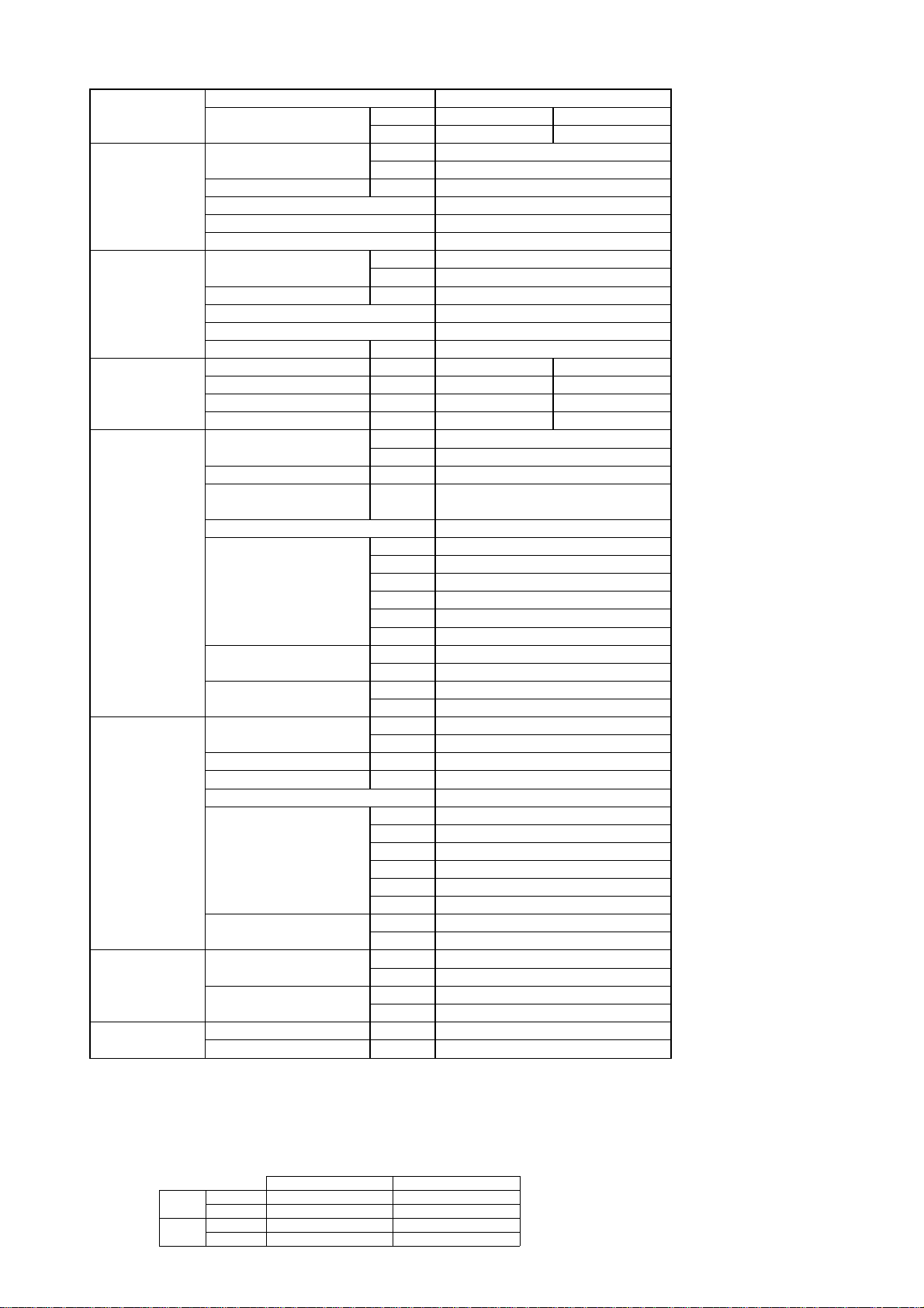
Model name Indoor unit PMH-P25BA PMH-P35BA
Outdoor unit PUH-P25VGAA PUH-P35VGAA PUH-P35YGAA
Cooling Capacity Btu/h 10,600 14,800
kW 3.1 4.35
Total input kW 1.14 1.66
EER 2.72 2.62
Energy label class D D
SHF 0.77 0.70
Heating Capacity Btu/h 11,400 16,900
kW 3.35 4.95
Total input kW 1.05 1.64
COP 3.19 3.02
Energy label class D D
Booster heater kW - -
Power supply Phase [ 13
Cycle Hz 50 50
Voltage V 230 400
Breaker size A 16 16
Indoor unit Air flow CMM 6.3-6.8-7.6-8.4 7-8-9-10
(Low-Medium2-Medium1-High)
CFM 220-240-270-300 250-280-320-350
External pressure Pa 0
Sound level dB(A) 29-31-33-35 34-36-38-40
(Low-Medium2-Medium1-High)
External finish (Panel) White Munsell 0.98Y 8.99/0.63
Dimension W : mm 854(1000)
Unit (Panel) D : mm 395(470)
H : mm 230(30)
W : inch 33-5/8(39-3/8)
D : inch 15-9/16(18-1/2)
H : inch 9-1/16(1-3/16)
Weight kg 14(3)
Unit (Panel) lbs 31(6.6)
Unit drain pipe I.D. mm 26
inch 1
Outdoor unit Air flow CMM 45
CFM 1,590
Sound level at cooling dB(A) 47
Sound level at heating dB(A) 49
External finish Ivory Munsell 5Y 7/1
Dimension W : mm 900
D : mm 330+20
H : mm 650
W : inch 35-7/16
D : inch 13 + 3/4
H : inch 25-5/8
Weight kg 50 54
lbs 110 119
Refrigerant pipe Gas side O.D. mm 12.7 15.88
size inch 1/2 5/8
Liquid side O.D. mm 6.35 9.52
inch 1/4 3/8
Refrigerant pipe Height difference m Max. 30 Max. 40
length Length m Max. 30 Max. 40
NOTE: 1. Rating conditions (ISO T1)
Cooling Indoor : D.B. 27: (80˚F) W.B. 19: (66˚F) Outdoor : D.B. 35: (95˚F) W.B. 24: (75˚F)
Heating Indoor: D.B. 20: (68˚F) Outdoor : D.B. 7: (45˚F) W.B. 6: (43˚F)
Refrigerant piping length (one way) : 5m (16ft.)
2. Guaranteed operating range
Indoor Outdoor
Cooling
Upper limit
D.B. 35˚C, W.B. 22.5˚C
D.B. 46˚C
Lower limit
D.B. 19˚C, W.B. 15˚C D.B. -5˚C
Heating
Upper limit
D.B. 28˚C
D.B. 24˚C, W.B. 18˚C
Lower limit
D.B. 17˚C
D.B. -11˚C, W.B. -12˚C
4. Above data based on indicated voltage
Indoor unit Single phase 230V 50Hz
Single phase 230V 50Hz / 3phase 400V 50Hz
Outdoor unit
3. Guaranteed voltage
198~264V, 50Hz : Single phase
342~457V, 50Hz : 3phase
9
Model name Indoor unit PMH-P50BA
Outdoor unit PUH-P50VGAA PUH-P50YGAA
Cooling Capacity Btu/h 18,300
kW 5.35
Total input kW 2.31
EER 2.32
Energy label class F
SHF 0.67
Heating Capacity Btu/h 21,200
kW 6.2
Total input kW 2.37
COP 2.62
Energy label class E
Booster heater kW -
Power supply Phase [ 13
Cycle Hz 50 50
Voltage V 230 400
Breaker size A 25 16
Indoor unit Air flow CMM 8-9-10-11
(Low-Medium2-Medium1-High)
CFM 282-318-353-388
External pressure Pa 0
Sound level dB(A) 36-38-40-42
(Low-Medium2-Medium1-High)
External finish (Panel) White Munsell 0.98Y 8.99/0.63
Dimension W : mm 854(1000)
Unit (Panel) D : mm 395(470)
H : mm 230(30)
W : inch 33-5/8(39-3/8)
D : inch 15-9/16(18-1/2)
H : inch 9-1/16(1-3/16)
Weight kg 14(3)
Unit (Panel) lbs 31(6.6)
Unit drain pipe I.D. mm 26
inch 1
Outdoor unit Air flow CMM 55
CFM 1,940
Sound level at cooling dB(A) 48
Sound level at heating dB(A) 50
External finish Ivory Munsell 5Y 7/1
Dimension W : mm 900
D : mm 330+20
H : mm 855
W : inch 35-7/16
D : inch 13 + 3/4
H : inch 33-5/8
Weight kg 74
lbs 163
Refrigerant pipe Gas side O.D. mm 15.88
size inch 5/8
Liquid side O.D. mm 9.52
inch 3/8
Refrigerant pipe Height difference m Max. 40
length Length m Max. 40
NOTE: 1. Rating conditions (ISO T1)
Cooling Indoor : D.B. 27: (80˚F) W.B. 19: (66˚F) Outdoor : D.B. 35: (95˚F) W.B. 24: (75˚F)
Heating Indoor: D.B. 20: (68˚F) Outdoor : D.B. 7: (45˚F) W.B. 6: (43˚F)
Refrigerant piping length (one way) : 5m (16ft.)
2. Guaranteed operating range
Indoor Outdoor
Cooling
Upper limit
D.B. 35˚C, W.B. 22.5˚C
D.B. 46˚C
Lower limit
D.B. 19˚C, W.B. 15˚C D.B. -5˚C
Heating
Upper limit
D.B. 28˚C
D.B. 24˚C, W.B. 18˚C
Lower limit
D.B. 17˚C
D.B. -11˚C, W.B. -12˚C
4. Above data based on indicated voltage
Indoor unit Single phase 230V 50Hz
Single phase 230V 50Hz / 3phase 400V 50Hz
Outdoor unit
3. Guaranteed voltage
198~264V, 50Hz : Single phase
342~457V, 50Hz : 3phase
10
2-2. CEILING-CONCEALED TYPE
2-2-1.HEAT PUMP (without HEATER) AND COOLING ONLY TYPE
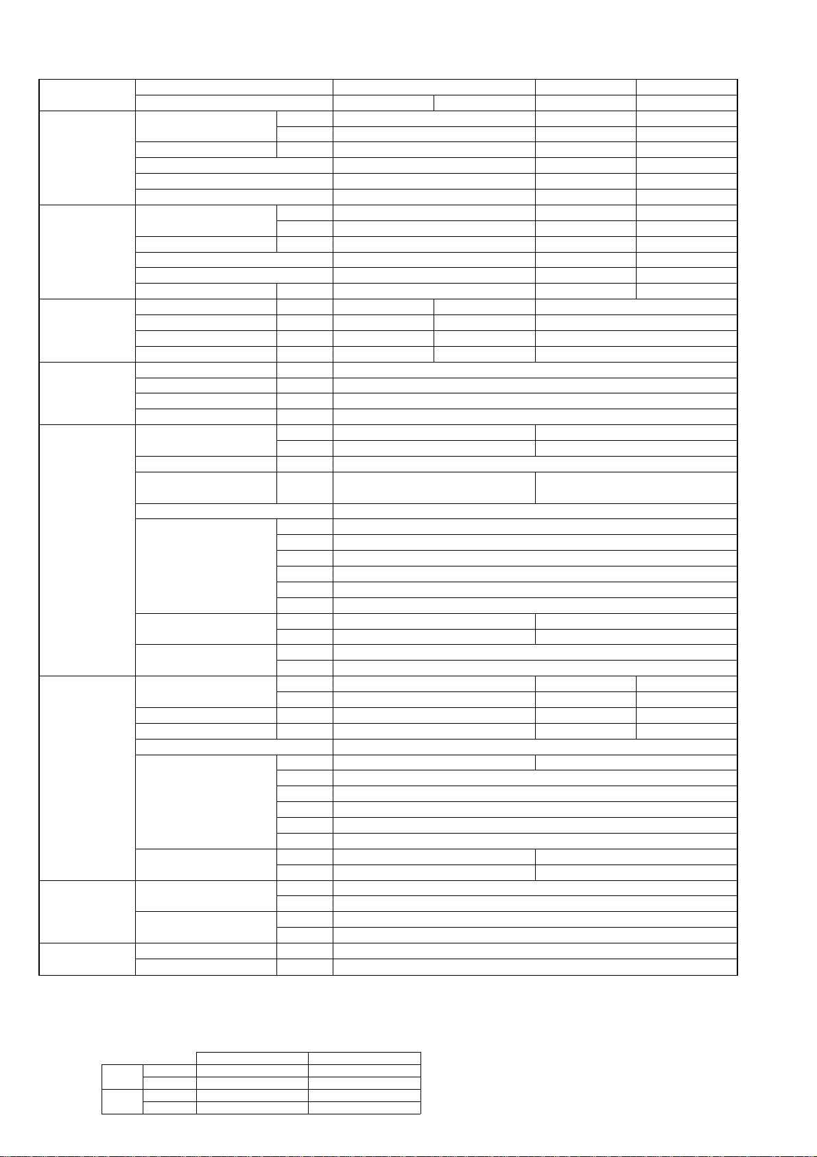
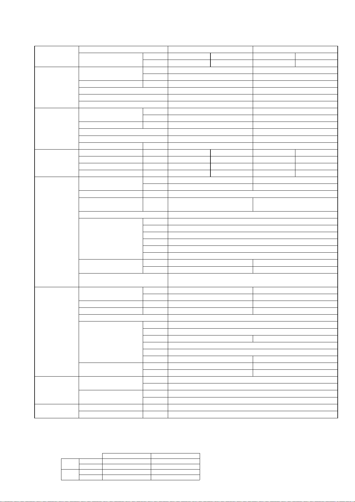
Model name Indoor unit PEAD-RP35EA PEAD-RP50EA
Outdoor unit H/P PUH-P35VGAA PUH-P35YGAA PUH-P50VGAA PUH-P50YGAA
C/O PU-P35VGAA PU-P35YGAA PU-P50VGAA PU-P50YGAA
Cooling Capacity Btu/h 15,100 19,100
kW 4.45 5.6
Total input kW 1.71 2.53
EER 2.60 2.21
Energy label class E F
SHF 0.72 0.74
Heating * Capacity Btu/h 16,500 21,400
kW 4.85 6.3
Total input kW 1.73 2.20
COP 2.80 2.86
Energy label class E D
Booster heater kW - -
Power supply Phase [ 1313
Cycle Hz 50 50 50 50
Voltage V 230 400 230 400
Breaker size A 16 16 25 16
Indoor unit Air flow CMM 11-14 13.5-17
(Low-High) CFM 388-494 476-600
External pressure Pa 30(70)
Sound level dB(A) 34-38 36-40
(Low-High) (70Pa : 36-43) (70Pa : 38-44)
External finish Galvanized sheets
Dimension W : mm 935
D : mm 700
H : mm 295
W : inch 36-13/16
D : inch 27-5/8
H : inch 11-5/8
Weight kg 33 35
lbs 73 77
Unit drain pipe R1(External thread)
Outdoor unit Air flow CMM 45 55
CFM 1,590 1,940
Sound level at cooling dB(A) 47 48
Sound level at heating * dB(A) 49 50
External finish Ivory Munsell 5Y 7/1
Dimension W : mm 900
D : mm 330+20
H : mm 650 855
W : inch 35-7/16
D : inch 13 + 3/4
H : inch 25-5/8 33-5/8
Weight kg 54 74
lbs 119 163
Refrigerant pipe Gas side O.D. mm 15.88
size inch 5/8
Liquid side O.D. mm 9.52
inch 3/8
Refrigerant pipe Height difference m Max. 40
length Length m Max. 40
* HEAT PUMP TYPE
NOTE: 1. Rating conditions (ISO T1)
Cooling Indoor : D.B. 27: (80˚F) W.B. 19: (66˚F) Outdoor : D.B. 35: (95˚F) W.B. 24: (75˚F)
Heating Indoor: D.B. 20: (68˚F) Outdoor : D.B. 7: (45˚F) W.B. 6: (43˚F)
Refrigerant piping length (one way) : 5m (16ft.)
2. Guaranteed operating range
Indoor Outdoor
Cooling
Upper limit
D.B. 35˚C, W.B. 22.5˚C
D.B. 46˚C
Lower limit
D.B. 19˚C, W.B. 15˚C D.B. -5˚C
Heating
Upper limit
D.B. 28˚C
D.B. 24˚C, W.B. 18˚C
Lower limit
D.B. 17˚C
D.B. -11˚C, W.B. -12˚C
4. Above data based on indicated voltage
Indoor unit Single phase 230V 50Hz
Single phase 230V 50Hz / 3phase 400V 50Hz
Outdoor unit
3. Guaranteed voltage
198~264V, 50Hz : Single phase
342~457V, 50Hz : 3phase
11
Model name Indoor unit PEAD-RP60EA PEAD-RP71EA
Outdoor unit H/P PUH-P60VGAA PUH-P60YGAA PUH-P71VGAA PUH-P71YGAA
C/O PU-P60VGAA PU-P60YGAA PU-P71VGAA PU-P71YGAA
Cooling Capacity Btu/h 22,500 25,900
kW 6.6 7.6
Total input kW 2.65 3.35
EER 2.49 2.27
Energy label class E F
SHF 0.71 0.78
Heating * Capacity Btu/h 24,300 30,800
kW 7.15 9.05
Total input kW 2.36 3.18
COP 3.03 2.85
Energy label class D D
Booster heater kW - -
Power supply Phase [ 1313
Cycle Hz 50 50 50 50
Voltage V 230 400 230 400
Breaker size A 25 16 32 16
Indoor unit Air flow CMM 17-21 20-25
(Low-High) CFM 600-741 706-883
External pressure Pa 30(70) 70(130)
Sound level dB(A) 37-41 37-41
(Low-High) (70Pa : 39-46) (130Pa : 40-45)
External finish Galvanized sheets
Dimension W : mm 1175
D : mm 700
H : mm 295
W : inch 46-1/8
D : inch 27-5/8
H : inch 11-5/8
Weight kg 42 44
lbs 92 97
Unit drain pipe R1(External thread)
Outdoor unit Air flow CMM 50
CFM 1,770
Sound level at cooling dB(A) 48 49
Sound level at heating * dB(A) 50 51
External finish Ivory Munsell 5Y 7/1
Dimension W : mm 900
D : mm 330+20
H : mm 855
W : inch 35-7/16
D : inch 13 + 3/4
H : inch 33-5/8
Weight kg 79
lbs 174
Refrigerant pipe Gas side O.D. mm 15.88
size inch 5/8
Liquid side O.D. mm 9.52
inch 3/8
Refrigerant pipe Height difference m Max. 50
length Length m Max. 50
* HEAT PUMP TYPE
NOTE: 1. Rating conditions (ISO T1)
Cooling Indoor : D.B. 27: (80˚F) W.B. 19: (66˚F) Outdoor : D.B. 35: (95˚F) W.B. 24: (75˚F)
Heating Indoor: D.B. 20: (68˚F) Outdoor : D.B. 7: (45˚F) W.B. 6: (43˚F)
Refrigerant piping length (one way) : 5m (16ft.)
2. Guaranteed operating range
Indoor Outdoor
Cooling
Upper limit
D.B. 35˚C, W.B. 22.5˚C
D.B. 46˚C
Lower limit
D.B. 19˚C, W.B. 15˚C D.B. -5˚C
Heating
Upper limit
D.B. 28˚C
D.B. 24˚C, W.B. 18˚C
Lower limit
D.B. 17˚C
D.B. -11˚C, W.B. -12˚C
4. Above data based on indicated voltage
Indoor unit Single phase 230V 50Hz
Single phase 230V 50Hz / 3phase 400V 50Hz
Outdoor unit
3. Guaranteed voltage
198~264V, 50Hz : Single phase
342~457V, 50Hz : 3phase
12
Model name Indoor unit PEAD-RP100EA PEAD-RP125EA PEAD-RP140EA
Outdoor unit H/P PUH-P100VGAA PUH-P100YGAA PUH-P125YGAA PUH-P140YGAA
C/O PU-P100VGAA PU-P100YGAA PU-P125YGAA PU-P140YGAA
Cooling Capacity Btu/h 32,700 41,600 47,700
kW 9.6 12.2 14
Total input kW 3.83 4.87 5.81
EER 2.51 2.51 2.41
Energy label class E E E
SHF 0.75 0.74 0.74
Heating * Capacity Btu/h 35,100 47,700 56,600
kW 10.3 14 16.6
Total input kW 4.00 4.74 5.90
COP 2.58 2.95 2.81
Energy label class F D D
Booster heater kW - - -
Power supply Phase [ 13 3
Cycle Hz 50 50 50
Voltage V 230 400 400
Breaker size A 32 16 25
Indoor unit Air flow CMM 27-34 33.5-42 36.5-46
(Low-High) CFM 953-1200 1183-1483 1288-1624
External pressure Pa 70(130)
Sound level dB(A) 41-46 44-50 46-51
(Low-High) (130Pa : 42-48) (130Pa : 46-52) (130Pa : 47-53)
External finish Galvanized sheets
Dimension W : mm 1415 1715
D : mm 700 740
H : mm 295 325
W : inch 55-11/16 67-1/2
D : inch 27-5/8 29-1/8
H : inch 11-5/8 12-13/16
Weight kg 62 65 70
lbs 136 143 154
Unit drain pipe R1(External thread)
Outdoor unit Air flow CMM 85 95 100
CFM 3,000 3,360 3,530
Sound level at cooling dB(A) 51 55 57
Sound level at heating * dB(A) 53 56 58
External finish Ivory Munsell 5Y 7/1
Dimension W : mm 900 1050
D : mm 330+20
H : mm 1260
W : inch 35-7/16 41-5/16
D : inch 13 + 3/4
H : inch 49-5/8
Weight kg 97 125
lbs 214 276
Refrigerant pipe Gas side O.D. mm 19.05
size inch 3/4
Liquid side O.D. mm 9.52
inch 3/8
Refrigerant pipe Height difference m Max. 50
length Length m Max. 50
* HEAT PUMP TYPE
NOTE: 1. Rating conditions (ISO T1)
Cooling Indoor : D.B. 27: (80˚F) W.B. 19: (66˚F) Outdoor : D.B. 35: (95˚F) W.B. 24: (75˚F)
Heating Indoor: D.B. 20: (68˚F) Outdoor : D.B. 7: (45˚F) W.B. 6: (43˚F)
Refrigerant piping length (one way) : 5m (16ft.)
2. Guaranteed operating range
Indoor Outdoor
Cooling
Upper limit
D.B. 35˚C, W.B. 22.5˚C
D.B. 46˚C
Lower limit
D.B. 19˚C, W.B. 15˚C D.B. -5˚C
Heating
Upper limit
D.B. 28˚C
D.B. 24˚C, W.B. 18˚C
Lower limit
D.B. 17˚C
D.B. -11˚C, W.B. -12˚C
4. Above data based on indicated voltage
Indoor unit Single phase 230V 50Hz
Single phase 230V 50Hz / 3phase 400V 50Hz
Outdoor unit
3. Guaranteed voltage
198~264V, 50Hz : Single phase
342~457V, 50Hz : 3phase
13
Model name Indoor unit PEAD-RP60GA PEAD-RP71GA
Outdoor unit H/P PUH-P60VGAA PUH-P60YGAA PUH-P71VGAA PUH-P71YGAA
C/O PU-P60VGAA PU-P60YGAA PU-P71VGAA PU-P71YGAA
Cooling Capacity Btu/h 22,500 25,900
kW 6.6 7.6
Total input kW 2.74 3.35
EER 2.41 2.27
Energy label class E F
SHF 0.72 0.76
Heating * Capacity Btu/h 24,300 30,800
kW 7.15 9.05
Total input kW 2.50 3.18
COP 2.86 2.85
Energy label class D D
Booster heater kW - -
Power supply Phase [ 1313
Cycle Hz 50 50 50 50
Voltage V 230 400 230 400
Breaker size A 25 16 32 16
Indoor unit Air flow CMM 16.5-21 20-25
(Low-High) CFM 582-741 706-883
External pressure Pa 10/50/70
Sound level dB(A) 33-37/35-40/36-42 35-38/37-41/37-43
(Low-High) (10/50/70Pa) (10/50/70Pa)
External finish Galvanized sheets
Dimension W : mm 1171
D : mm 740
H : mm 275
W : inch 46-1/8
D : inch 29-1/8
H : inch 10-13/16
Weight kg 42
lbs 93
Unit drain pipe O.D. mm 32
inch 1-1/4
Outdoor unit Air flow CMM 50
CFM 1,770
Sound level at cooling dB(A) 48 49
Sound level at heating * dB(A) 50 51
External finish Ivory Munsell 5Y 7/1
Dimension W : mm 900
D : mm 330+20
H : mm 855
W : inch 35-7/16
D : inch 13 + 3/4
H : inch 33-5/8
Weight kg 79
lbs 174
Refrigerant pipe Gas side O.D. mm 15.88
size inch 5/8
Liquid side O.D. mm 9.52
inch 3/8
Refrigerant pipe Height difference m Max. 50
length Length m Max. 50
* HEAT PUMP TYPE
NOTE: 1. Rating conditions (ISO T1)
Cooling Indoor : D.B. 27: (80˚F) W.B. 19: (66˚F) Outdoor : D.B. 35: (95˚F) W.B. 24: (75˚F)
Heating Indoor: D.B. 20: (68˚F) Outdoor : D.B. 7: (45˚F) W.B. 6: (43˚F)
Refrigerant piping length (one way) : 5m (16ft.)
2. Guaranteed operating range
Indoor Outdoor
Cooling
Upper limit
D.B. 35˚C, W.B. 22.5˚C
D.B. 46˚C
Lower limit
D.B. 19˚C, W.B. 15˚C D.B. -5˚C
Heating
Upper limit
D.B. 28˚C
D.B. 24˚C, W.B. 18˚C
Lower limit
D.B. 17˚C
D.B. -11˚C, W.B. -12˚C
4. Above data based on indicated voltage
Indoor unit Single phase 230V 50Hz
Single phase 230V 50Hz / 3phase 400V 50Hz
Outdoor unit
3. Guaranteed voltage
198~264V, 50Hz : Single phase
342~457V, 50Hz : 3phase
14
Model name Indoor unit PEAD-RP100GA
Outdoor unit H/P PUH-P100VGAA PUH-P100YGAA
C/O PU-P100VGAA PU-P100YGAA
Cooling Capacity Btu/h 32,700
kW 9.6
Total input kW 3.68
EER 2.61
Energy label class D
SHF 0.75
Heating * Capacity Btu/h 35,100
kW 10.3
Total input kW 3.67
COP 2.81
Energy label class D
Booster heater kW -
Power supply Phase [ 13
Cycle Hz 50 50
Voltage V 230 400
Breaker size A 32 16
Indoor unit Air flow CMM 26.5-33
(Low-High) CFM 935-1165
External pressure Pa 10/50/70
Sound level dB(A) 40-43/42-45/42-46
(Low-High) (10/50/70Pa)
External finish Galvanized sheets
Dimension W mm 1411
D mm 740
H mm 275
W inch 55-9/16
D inch 29-1/8
H inch 10-13/16
Weight kg 50
lbs 111
Unit drain pipe mm 32
inch 1-1/4
Outdoor unit Air flow CMM 85
CFM 3,000
Sound level at cooling dB(A) 51
Sound level at heating * dB(A) 53
External finish Ivory Munsell 5Y 7/1
Dimension W mm 900
D mm 330+20
H mm 1260
W inch 35-7/16
D inch 13 + 3/4
H inch 49-5/8
Weight kg 97
lbs 214
Refrigerant pipe Gas side O.D. mm 19.05
size inch 3/4
Liquid side O.D. mm 9.52
inch 3/8
Refrigerant pipe Height difference m Max. 50
length Length m Max. 50
* HEAT PUMP TYPE
NOTE: 1. Rating conditions (ISO T1)
Cooling Indoor : D.B. 27: (80˚F) W.B. 19: (66˚F) Outdoor : D.B. 35: (95˚F) W.B. 24: (75˚F)
Heating Indoor: D.B. 20: (68˚F) Outdoor : D.B. 7: (45˚F) W.B. 6: (43˚F)
Refrigerant piping length (one way) : 5m (16ft.)
2. Guaranteed operating range
Indoor Outdoor
Cooling
Upper limit
D.B. 35˚C, W.B. 22.5˚C
D.B. 46˚C
Lower limit
D.B. 19˚C, W.B. 15˚C D.B. -5˚C
Heating
Upper limit
D.B. 28˚C
D.B. 24˚C, W.B. 18˚C
Lower limit
D.B. 17˚C
D.B. -11˚C, W.B. -12˚C
4. Above data based on indicated voltage
Indoor unit Single phase 230V 50Hz
Single phase 230V 50Hz / 3phase 400V 50Hz
Outdoor unit
3. Guaranteed voltage
198~264V, 50Hz : Single phase
342~457V, 50Hz : 3phase
15
2-2-2.HEAT PUMP (with HEATER) TYPE
Model name Indoor unit PEHD-P35EAH PEHD-P50EAH
Outdoor unit PUH-P35VGAA PUH-P35YGAA PUH-P50VGAA PUH-P50YGAA
Cooling Capacity Btu/h 15,100 19,100
kW 4.45 5.6
Total input kW 1.71 2.53
EER 2.60 2.21
Energy label class E F
SHF 0.72 0.74
Heating Capacity Btu/h 16,500 21,400
kW 4.85 6.3
Total input kW 1.73 2.20
COP 2.80 2.86
Energy label class E D
Booster heater kW 0.9 0.9
Power supply Phase [ 1313
Cycle Hz 50 50 50 50
Voltage V 230 400 230 400
Breaker size A 16 16 25 16
Power supply Phase [ 1
for heater Cycle Hz 50
Voltage V 230
Breaker size A 16
Indoor unit Air flow CMM 11-14 13.5-17
(Low-High) CFM 388-494 476-600
External pressure Pa 30(70)
Sound level dB(A) 34-38 36-40
(Low-High) (70Pa : 36-43) (70Pa : 38-44)
External finish Galvanized sheets
Dimension W : mm 935
D : mm 700
H : mm 295
W : inch 36-13/16
D : inch 27-5/8
H : inch 11-5/8
Weight kg 35 37
lbs 77 82
Unit drain pipe R1(External thread)
Outdoor unit Air flow CMM 45 55
CFM 1,590 1,940
Sound level at cooling dB(A) 47 48
Sound level at heating dB(A) 49 50
External finish Ivory Munsell 5Y 7/1
Dimension W : mm 900
D : mm 330+20
H : mm 650 855
W : inch 35-7/16
D : inch 13 + 3/4
H : inch 25-5/8 33-5/8
Weight kg 54 74
lbs 119 163
Refrigerant pipe Gas side O.D. mm 15.88
size inch 5/8
Liquid side O.D. mm 9.52
inch 3/8
Refrigerant pipe Height difference m Max. 40
length Length m Max. 40
NOTE: 1. Rating conditions (ISO T1)
Cooling Indoor : D.B. 27: (80˚F) W.B. 19: (66˚F) Outdoor : D.B. 35: (95˚F) W.B. 24: (75˚F)
Heating Indoor: D.B. 20: (68˚F) Outdoor : D.B. 7: (45˚F) W.B. 6: (43˚F)
Refrigerant piping length (one way) : 5m (16ft.)
2. Guaranteed operating range
Indoor Outdoor
Cooling
Upper limit
D.B. 35˚C, W.B. 22.5˚C
D.B. 46˚C
Lower limit
D.B. 19˚C, W.B. 15˚C D.B. -5˚C
Heating
Upper limit
D.B. 28˚C
D.B. 24˚C, W.B. 18˚C
Lower limit
D.B. 17˚C
D.B. -11˚C, W.B. -12˚C
4. Above data based on indicated voltage
Indoor unit Single phase 230V 50Hz
Single phase 230V 50Hz / 3phase 400V 50Hz
Outdoor unit
3. Guaranteed voltage
198~264V, 50Hz : Single phase
342~457V, 50Hz : 3phase
16
Model name Indoor unit PEHD-P60EAH PEHD-P71EAH
Outdoor unit PUH-P60VGAA PUH-P60YGAA PUH-P71VGAA PUH-P71YGAA
Cooling Capacity Btu/h 22,500 25,900
kW 6.6 7.6
Total input kW 2.65 3.35
EER 2.49 2.27
Energy label class E F
SHF 0.71 0.78
Heating Capacity Btu/h 24,300 30,800
kW 7.15 9.05
Total input kW 2.36 3.18
COP 3.03 2.85
Energy label class D D
Booster heater kW 1.4 1.9
Power supply Phase [ 1313
Cycle Hz 50 50 50 50
Voltage V 230 400 230 400
Breaker size A 25 16 32 16
Power supply Phase [ 1
for heater Cycle Hz 50
Voltage V 230
Breaker size A 16
Indoor unit Air flow CMM 17-21 20-25
(Low-High) CFM 600-741 706-883
External pressure Pa 30(70) 70(130)
Sound level dB(A) 37-41 37-41
(Low-High) (70Pa : 39-46) (130Pa : 40-45)
External finish Galvanized sheets
Dimension W : mm 1175
D : mm 700
H : mm 295
W : inch 46-1/8
D : inch 27-5/8
H : inch 11-5/8
Weight kg 44 46
lbs 97 101
Unit drain pipe R1(External thread)
Outdoor unit Air flow CMM 50
CFM 1,770
Sound level at cooling dB(A) 48 49
Sound level at heating dB(A) 50 51
External finish Ivory Munsell 5Y 7/1
Dimension W : mm 900
D : mm 330+20
H : mm 855
W : inch 35-7/16
D : inch 13 + 3/4
H : inch 33-5/8
Weight kg 79
lbs 174
Refrigerant pipe Gas side O.D. mm 15.88
size inch 5/8
Liquid side O.D. mm 9.52
inch 3/8
Refrigerant pipe Height difference m Max. 50
length Length m Max. 50
NOTE: 1. Rating conditions (ISO T1)
Cooling Indoor : D.B. 27: (80˚F) W.B. 19: (66˚F) Outdoor : D.B. 35: (95˚F) W.B. 24: (75˚F)
Heating Indoor: D.B. 20: (68˚F) Outdoor : D.B. 7: (45˚F) W.B. 6: (43˚F)
Refrigerant piping length (one way) : 5m (16ft.)
2. Guaranteed operating range
Indoor Outdoor
Cooling
Upper limit
D.B. 35˚C, W.B. 22.5˚C
D.B. 46˚C
Lower limit
D.B. 19˚C, W.B. 15˚C D.B. -5˚C
Heating
Upper limit
D.B. 28˚C
D.B. 24˚C, W.B. 18˚C
Lower limit
D.B. 17˚C
D.B. -11˚C, W.B. -12˚C
4. Above data based on indicated voltage
Indoor unit Single phase 230V 50Hz
Single phase 230V 50Hz / 3phase 400V 50Hz
Outdoor unit
3. Guaranteed voltage
198~264V, 50Hz : Single phase
342~457V, 50Hz : 3phase
17
Model name Indoor unit PEHD-P100EAH PEHD-P125EAH PEHD-P140EAH
Outdoor unit PUH-P100VGAA PUH-P100YGAA PUH-P125YGAA PUH-P140YGAA
Cooling Capacity Btu/h 32,700 41,600 47,700
kW 9.6 12.2 14
Total input kW 3.83 4.87 5.81
EER 2.51 2.51 2.41
Energy label class E E E
SHF 0.75 0.74 0.74
Heating Capacity Btu/h 35,100 47,700 56,600
kW 10.3 14 16.6
Total input kW 4.00 4.74 5.90
COP 2.58 2.95 2.81
Energy label class F D D
Booster heater kW - - -
Power supply Phase [ 13 3
Cycle Hz 50 50 50
Voltage V 230 400 400
Breaker size A 32 16 25
Power supply Phase [ 1
for heater Cycle Hz 50
Voltage V 230
Breaker size A 16
Indoor unit Air flow CMM 27-34 33.5-42 36.5-46
(Low-High) CFM 953-1200 1183-1483 1288-1624
External pressure Pa 70(130)
Sound level dB(A) 41-46 44-50 46-51
(Low-High) (130Pa : 42-48) (130Pa : 46-52) (130Pa : 47-53)
External finish Galvanized sheets
Dimension W : mm 1415 1715
D : mm 700 740
H : mm 295 325
W : inch 55-11/16 67-1/2
D : inch 27-5/8 29-1/8
H : inch 11-5/8 12-13/16
Weight kg 65 68 73
lbs 143 150 161
Unit drain pipe R1(External thread)
Outdoor unit Air flow CMM 85 95 100
CFM 3,000 3,360 3,530
Sound level at cooling dB(A) 51 55 57
Sound level at heating dB(A) 53 56 58
External finish Ivory Munsell 5Y 7/1
Dimension W : mm 900 1050
D : mm 330+20
H : mm 1260
W : inch 35-7/16 41-5/16
D : inch 13 + 3/4
H : inch 49-5/8
Weight kg 97 125
lbs 214 276
Refrigerant pipe Gas side O.D. mm 19.05
size inch 3/4
Liquid side O.D. mm 9.52
inch 3/8
Refrigerant pipe Height difference m Max. 50
length Length m Max. 50
NOTE: 1. Rating conditions (ISO T1)
Cooling Indoor : D.B. 27: (80˚F) W.B. 19: (66˚F) Outdoor : D.B. 35: (95˚F) W.B. 24: (75˚F)
Heating Indoor: D.B. 20: (68˚F) Outdoor : D.B. 7: (45˚F) W.B. 6: (43˚F)
Refrigerant piping length (one way) : 5m (16ft.)
2. Guaranteed operating range
Indoor Outdoor
Cooling
Upper limit
D.B. 35˚C, W.B. 22.5˚C
D.B. 46˚C
Lower limit
D.B. 19˚C, W.B. 15˚C D.B. -5˚C
Heating
Upper limit
D.B. 28˚C
D.B. 24˚C, W.B. 18˚C
Lower limit
D.B. 17˚C
D.B. -11˚C, W.B. -12˚C
4. Above data based on indicated voltage
Indoor unit Single phase 230V 50Hz
Single phase 230V 50Hz / 3phase 400V 50Hz
Outdoor unit
3. Guaranteed voltage
198~264V, 50Hz : Single phase
342~457V, 50Hz : 3phase
18
2-3. WALL-MOUNTED TYPE
2-3-1.HEAT PUMP (without HEATER) AND COOLING ONLY TYPE
Model name Indoor unit PKA-RP35GAL PKA-RP50GAL
Outdoor unit H/P PUH-P35VGAA PUH-P35YGAA PUH-P50VGAA PUH-P50YGAA
C/O PU-P35VGAA PU-P35YGAA PU-P50VGAA PU-P50YGAA
Cooling Capacity Btu/h 15,100 18,300
kW 4.45 5.35
Total input kW 1.70 2.33
EER 2.62 2.30
Energy label class D F
SHF 0.77 0.70
Heating * Capacity Btu/h 16,900 21,200
kW 4.95 6.2
Total input kW 1.79 2.34
COP 2.77 2.65
Energy label class E E
Booster heater kW - -
Power supply Phase [ 1313
Cycle Hz 50 50 50 50
Voltage V 230 400 230 400
Breaker size A 16 16 25 16
Indoor unit Air flow CMM 9-10-11-12
(Low-Medium2-Medium1-High)
CFM 320-355-390-425
External pressure Pa 0
Sound level dB(A) 36-38-41-43
(Low-Medium2-Medium1-High)
External finish White Munsell 0.70Y 8.59/0.97
Dimension W : mm 990
D : mm 235
H : mm 340
W : inch 39
D : inch 9-1/4
H : inch 13-3/8
Weight kg 16
lbs 35
Unit drain pipe O.D. mm 20
inch 13/16
Outdoor unit Air flow CMM 45 55
CFM 1,590 1,940
Sound level at cooling dB(A) 47 48
Sound level at heating * dB(A) 49 50
External finish Ivory Munsell 5Y 7/1
Dimension W : mm 900
D : mm 330+20
H : mm 650 855
W : inch 35-7/16
D : inch 13 + 3/4
H : inch 25-5/8 33-5/8
Weight kg 54 74
lbs 119 163
Refrigerant pipe Gas side O.D. mm 15.88
size inch 5/8
Liquid side O.D. mm 9.52
inch 3/8
Refrigerant pipe Height difference m Max. 40
length Length m Max. 40
* HEAT PUMP TYPE
NOTE: 1. Rating conditions (ISO T1)
Cooling Indoor : D.B. 27: (80˚F) W.B. 19: (66˚F) Outdoor : D.B. 35: (95˚F) W.B. 24: (75˚F)
Heating Indoor: D.B. 20: (68˚F) Outdoor : D.B. 7: (45˚F) W.B. 6: (43˚F)
Refrigerant piping length (one way) : 5m (16ft.)
2. Guaranteed operating range
Indoor Outdoor
Cooling
Upper limit
D.B. 35˚C, W.B. 22.5˚C
D.B. 46˚C
Lower limit
D.B. 19˚C, W.B. 15˚C D.B. -5˚C
Heating
Upper limit
D.B. 28˚C
D.B. 24˚C, W.B. 18˚C
Lower limit
D.B. 17˚C
D.B. -11˚C, W.B. -12˚C
4. Above data based on indicated voltage
Indoor unit Single phase 230V 50Hz
Single phase 230V 50Hz / 3phase 400V 50Hz
Outdoor unit
3. Guaranteed voltage
198~264V, 50Hz : Single phase
342~457V, 50Hz : 3phase
19
Model name Indoor unit PKA-RP60FAL PKA-RP71FAL
Outdoor unit H/P PUH-P60VGAA PUH-P60YGAA PUH-P71VGAA PUH-P71YGAA
C/O PU-P60VGAA PU-P60YGAA PU-P71VGAA PU-P71YGAA
Cooling Capacity Btu/h 22,000 26,800
kW 6.45 7.85
Total input kW 2.65 3.43
EER 2.43 2.29
Energy label class E F
SHF 0.80 0.74
Heating * Capacity Btu/h 25,100 32,100
kW 7.35 9.4
Total input kW 2.63 3.61
COP 2.79 2.60
Energy label class E F
Booster heater kW - -
Power supply Phase [ 1313
Cycle Hz 50 50 50 50
Voltage V 230 400 230 400
Breaker size A 25 16 32 16
Indoor unit Air flow CMM 15-20
(Low-High) CFM 530-705
External pressure Pa 0
Sound level dB(A) 39-45
(Low-High)
External finish Munsell 3.4Y 7.7/0.8
Dimension W : mm 1400
D : mm 235
H : mm 340
W : inch 55-1/8
D : inch 9-1/4
H : inch 13-3/8
Weight kg 24
lbs 53
Unit drain pipe O.D. mm 20
inch 13/16
Outdoor unit Air flow CMM 50
CFM 1,770
Sound level at cooling dB(A) 48 49
Sound level at heating * dB(A) 50 51
External finish Ivory Munsell 5Y 7/1
Dimension W : mm 900
D : mm 330+20
H : mm 855
W : inch 35-7/16
D : inch 13 + 3/4
H : inch 33-5/8
Weight kg 79
lbs 174
Refrigerant pipe Gas side O.D. mm 15.88
size inch 5/8
Liquid side O.D. mm 9.52
inch 3/8
Refrigerant pipe Height difference m Max. 50
length Length m Max. 50
* HEAT PUMP TYPE
NOTE: 1. Rating conditions (ISO T1)
Cooling Indoor : D.B. 27: (80˚F) W.B. 19: (66˚F) Outdoor : D.B. 35: (95˚F) W.B. 24: (75˚F)
Heating Indoor: D.B. 20: (68˚F) Outdoor : D.B. 7: (45˚F) W.B. 6: (43˚F)
Refrigerant piping length (one way) : 5m (16ft.)
2. Guaranteed operating range
Indoor Outdoor
Cooling
Upper limit
D.B. 35˚C, W.B. 22.5˚C
D.B. 46˚C
Lower limit
D.B. 19˚C, W.B. 15˚C D.B. -5˚C
Heating
Upper limit
D.B. 28˚C
D.B. 24˚C, W.B. 18˚C
Lower limit
D.B. 17˚C
D.B. -11˚C, W.B. -12˚C
4. Above data based on indicated voltage
Indoor unit Single phase 230V 50Hz
Single phase 230V 50Hz / 3phase 400V 50Hz
Outdoor unit
3. Guaranteed voltage
198~264V, 50Hz : Single phase
342~457V, 50Hz : 3phase
20
Model name Indoor unit PKA-RP100FAL
Outdoor unit H/P PUH-P100VGAA PUH-P100YGAA
C/O PU-P100VGAA PU-P100YGAA
Cooling Capacity Btu/h 32,100
kW 9.4
Total input kW 3.59
EER 2.62
Energy label class D
SHF 0.76
Heating * Capacity Btu/h 36,800
kW 10.8
Total input kW 3.77
COP 2.86
Energy label class D
Booster heater kW -
Power supply Phase [ 13
Cycle Hz 50 50
Voltage V 230 400
Breaker size A 32 16
Indoor unit Air flow CMM 22-28
(Low-High) CFM 780-990
External pressure Pa 0
Sound level dB(A) 41-46
(Low-High)
External finish Munsell 3.4Y 7.7/0.8
Dimension W : mm 1680
D : mm 235
H : mm 340
W : inch 66-1/8
D : inch 9-1/4
H : inch 13-3/8
Weight kg 28
lbs 62
Unit drain pipe O.D. mm 20
inch 13/16
Outdoor unit Air flow CMM 85
CFM 3,000
Sound level at cooling dB(A) 51
Sound level at heating * dB(A) 53
External finish Ivory Munsell 5Y 7/1
Dimension W : mm 900
D : mm 330+20
H : mm 1260
W : inch 35-7/16
D : inch 13 + 3/4
H : inch 49-5/8
Weight kg 97
lbs 214
Refrigerant pipe Gas side O.D. mm 19.05
size inch 3/4
Liquid side O.D. mm 9.52
inch 3/8
Refrigerant pipe Height difference m Max. 50
length Length m Max. 50
* HEAT PUMP TYPE
NOTE: 1. Rating conditions (ISO T1)
Cooling Indoor : D.B. 27: (80˚F) W.B. 19: (66˚F) Outdoor : D.B. 35: (95˚F) W.B. 24: (75˚F)
Heating Indoor: D.B. 20: (68˚F) Outdoor : D.B. 7: (45˚F) W.B. 6: (43˚F)
Refrigerant piping length (one way) : 5m (16ft.)
2. Guaranteed operating range
Indoor Outdoor
Cooling
Upper limit
D.B. 35˚C, W.B. 22.5˚C
D.B. 46˚C
Lower limit
D.B. 19˚C, W.B. 15˚C D.B. -5˚C
Heating
Upper limit
D.B. 28˚C
D.B. 24˚C, W.B. 18˚C
Lower limit
D.B. 17˚C
D.B. -11˚C, W.B. -12˚C
4. Above data based on indicated voltage
Indoor unit Single phase 230V 50Hz
Single phase 230V 50Hz / 3phase 400V 50Hz
Outdoor unit
3. Guaranteed voltage
198~264V, 50Hz : Single phase
342~457V, 50Hz : 3phase
21
2-3-2.HEAT PUMP (with HEATER) TYPE
Model name Indoor unit PKH-P35GALH PKH-P50GALH
Outdoor unit PUH-P35VGAA PUH-P35YGAA PUH-P50VGAA PUH-P50YGAA
Cooling Capacity Btu/h 15,100 18,300
kW 4.45 5.35
Total input kW 1.70 2.33
EER 2.62 2.30
Energy label class D F
SHF 0.77 0.70
Heating Capacity Btu/h 16,900 21,200
kW 4.95 6.2
Total input kW 1.79 2.34
COP 2.77 2.65
Energy label class E E
Booster heater kW 0.73 0.73
Power supply Phase [ 1313
Cycle Hz 50 50 50 50
Voltage V 230 400 230 400
Breaker size A 16 16 25 16
Power supply Phase [ 1
for heater Cycle Hz 50
Voltage V 230
Breaker size A 16
Indoor unit Air flow CMM 9-10-11-12
(Low-Medium2-Medium1-High)
CFM 320-355-390-425
External pressure Pa 0
Sound level dB(A) 36-38-41-43
(Low-Medium2-Medium1-High)
External finish White Munsell 0.70Y 8.59/0.97
Dimension W : mm 990
D : mm 235
H : mm 340
W : inch 39
D : inch 9-1/4
H : inch 13-3/8
Weight kg 17
lbs 37
Unit drain pipe O.D. mm 20
inch 13/16
Outdoor unit Air flow CMM 45 55
CFM 1,590 1,940
Sound level at cooling dB(A) 47 48
Sound level at heating dB(A) 49 50
External finish Ivory Munsell 5Y 7/1
Dimension W : mm 900
D : mm 330+20
H : mm 650 855
W : inch 35-7/16
D : inch 13 + 3/4
H : inch 25-5/8 33-5/8
Weight kg 54 74
lbs 119 163
Refrigerant pipe Gas side O.D. mm 15.88
size inch 5/8
Liquid side O.D. mm 9.52
inch 3/8
Refrigerant pipe Height difference m Max. 40
length Length m Max. 40
NOTE: 1. Rating conditions (ISO T1)
Cooling Indoor : D.B. 27: (80˚F) W.B. 19: (66˚F) Outdoor : D.B. 35: (95˚F) W.B. 24: (75˚F)
Heating Indoor: D.B. 20: (68˚F) Outdoor : D.B. 7: (45˚F) W.B. 6: (43˚F)
Refrigerant piping length (one way) : 5m (16ft.)
2. Guaranteed operating range
Indoor Outdoor
Cooling
Upper limit
D.B. 35˚C, W.B. 22.5˚C
D.B. 46˚C
Lower limit
D.B. 19˚C, W.B. 15˚C D.B. -5˚C
Heating
Upper limit
D.B. 28˚C
D.B. 24˚C, W.B. 18˚C
Lower limit
D.B. 17˚C
D.B. -11˚C, W.B. -12˚C
4. Above data based on indicated voltage
Indoor unit Single phase 230V 50Hz
Single phase 230V 50Hz / 3phase 400V 50Hz
Outdoor unit
3. Guaranteed voltage
198~264V, 50Hz : Single phase
342~457V, 50Hz : 3phase
22
Model name Indoor unit PKH-P60FALH PKH-P71FALH
Outdoor unit PUH-P60VGAA PUH-P60YGAA PUH-P71VGAA PUH-P71YGAA
Cooling Capacity Btu/h 22,000 26,800
kW 6.45 7.85
Total input kW 2.65 3.43
EER 2.43 2.29
Energy label class E F
SHF 0.80 0.74
Heating Capacity Btu/h 25,100 32,100
kW 7.35 9.4
Total input kW 2.63 3.61
COP 2.79 2.60
Energy label class E F
Booster heater kW 1.93 1.93
Power supply Phase [ 1313
Cycle Hz 50 50 50 50
Voltage V 230 400 230 400
Breaker size A 25 16 32 16
Power supply Phase [ 1
for heater Cycle Hz 50
Voltage V 230
Breaker size A 16
Indoor unit Air flow CMM 15-20
(Low-High) CFM 530-705
External pressure Pa 0
Sound level dB(A) 39-45
(Low-High)
External finish Munsell 3.4Y 7.7/0.8
Dimension W : mm 1400
D : mm 235
H : mm 340
W : inch 55-1/8
D : inch 9-1/4
H : inch 13-3/8
Weight kg 26
lbs 57
Unit drain pipe O.D. mm 20
inch 13/16
Outdoor unit Air flow CMM 50
CFM 1,770
Sound level at cooling dB(A) 48 49
Sound level at heating dB(A) 50 51
External finish Ivory Munsell 5Y 7/1
Dimension W : mm 900
D : mm 330+20
H : mm 855
W : inch 35-7/16
D : inch 13 + 3/4
H : inch 33-5/8
Weight kg 79
lbs 174
Refrigerant pipe Gas side O.D. mm 15.88
size inch 5/8
Liquid side O.D. mm 9.52
inch 3/8
Refrigerant pipe Height difference m Max. 50
length Length m Max. 50
NOTE: 1. Rating conditions (ISO T1)
Cooling Indoor : D.B. 27: (80˚F) W.B. 19: (66˚F) Outdoor : D.B. 35: (95˚F) W.B. 24: (75˚F)
Heating Indoor: D.B. 20: (68˚F) Outdoor : D.B. 7: (45˚F) W.B. 6: (43˚F)
Refrigerant piping length (one way) : 5m (16ft.)
2. Guaranteed operating range
Indoor Outdoor
Cooling
Upper limit
D.B. 35˚C, W.B. 22.5˚C
D.B. 46˚C
Lower limit
D.B. 19˚C, W.B. 15˚C D.B. -5˚C
Heating
Upper limit
D.B. 28˚C
D.B. 24˚C, W.B. 18˚C
Lower limit
D.B. 17˚C
D.B. -11˚C, W.B. -12˚C
4. Above data based on indicated voltage
Indoor unit Single phase 230V 50Hz
Single phase 230V 50Hz / 3phase 400V 50Hz
Outdoor unit
3. Guaranteed voltage
198~264V, 50Hz : Single phase
342~457V, 50Hz : 3phase
23
Model name Indoor unit PKH-P100FALH
Outdoor unit PUH-P100VGAA PUH-P100YGAA
Cooling Capacity Btu/h 32,100
kW 9.4
Total input kW 3.59
EER 2.62
Energy label class D
SHF 0.76
Heating Capacity Btu/h 36,800
kW 10.8
Total input kW 3.77
COP 2.86
Energy label class D
Booster heater kW 2.20
Power supply Phase [ 13
Cycle Hz 50 50
Voltage V 230 400
Breaker size A 32 16
Power supply Phase [ 1
for heater Cycle Hz 50
Voltage V 230
Breaker size A 16
Indoor unit Air flow CMM 22-28
(Low-High) CFM 780-990
External pressure Pa 0
Sound level dB(A) 41-46
(Low-High)
External finish Munsell 3.4Y 7.7/0.8
Dimension W : mm 1680
D : mm 235
H : mm 340
W : inch 66-1/8
D : inch 9-1/4
H : inch 13-3/8
Weight kg 30
lbs 66
Unit drain pipe O.D. mm 20
inch 13/16
Outdoor unit Air flow CMM 85
CFM 3,000
Sound level at cooling dB(A) 51
Sound level at heating dB(A) 53
External finish Ivory Munsell 5Y 7/1
Dimension W : mm 900
D : mm 330+20
H : mm 1260
W : inch 35-7/16
D : inch 13 + 3/4
H : inch 49-5/8
Weight kg 97
lbs 214
Refrigerant pipe Gas side O.D. mm 19.05
size inch 3/4
Liquid side O.D. mm 9.52
inch 3/8
Refrigerant pipe Height difference m Max. 50
length Length m Max. 50
NOTE: 1. Rating conditions (ISO T1)
Cooling Indoor : D.B. 27: (80˚F) W.B. 19: (66˚F) Outdoor : D.B. 35: (95˚F) W.B. 24: (75˚F)
Heating Indoor: D.B. 20: (68˚F) Outdoor : D.B. 7: (45˚F) W.B. 6: (43˚F)
Refrigerant piping length (one way) : 5m (16ft.)
2. Guaranteed operating range
Indoor Outdoor
Cooling
Upper limit
D.B. 35˚C, W.B. 22.5˚C
D.B. 46˚C
Lower limit
D.B. 19˚C, W.B. 15˚C D.B. -5˚C
Heating
Upper limit
D.B. 28˚C
D.B. 24˚C, W.B. 18˚C
Lower limit
D.B. 17˚C
D.B. -11˚C, W.B. -12˚C
4. Above data based on indicated voltage
Indoor unit Single phase 230V 50Hz
Single phase 230V 50Hz / 3phase 400V 50Hz
Outdoor unit
3. Guaranteed voltage
198~264V, 50Hz : Single phase
342~457V, 50Hz : 3phase
24
2-4. CEILING-SUSPENDED TYPE
2-4-1.HEAT PUMP (without HEATER) AND COOLING ONLY TYPE
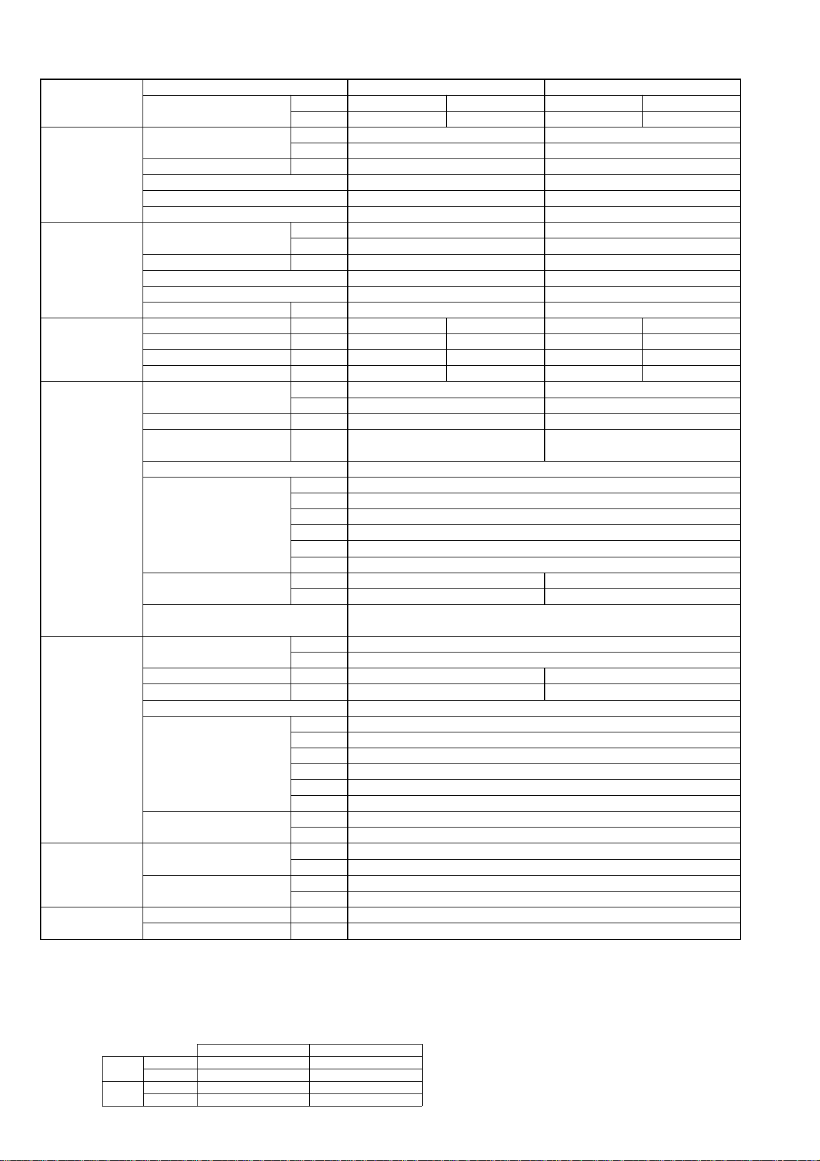
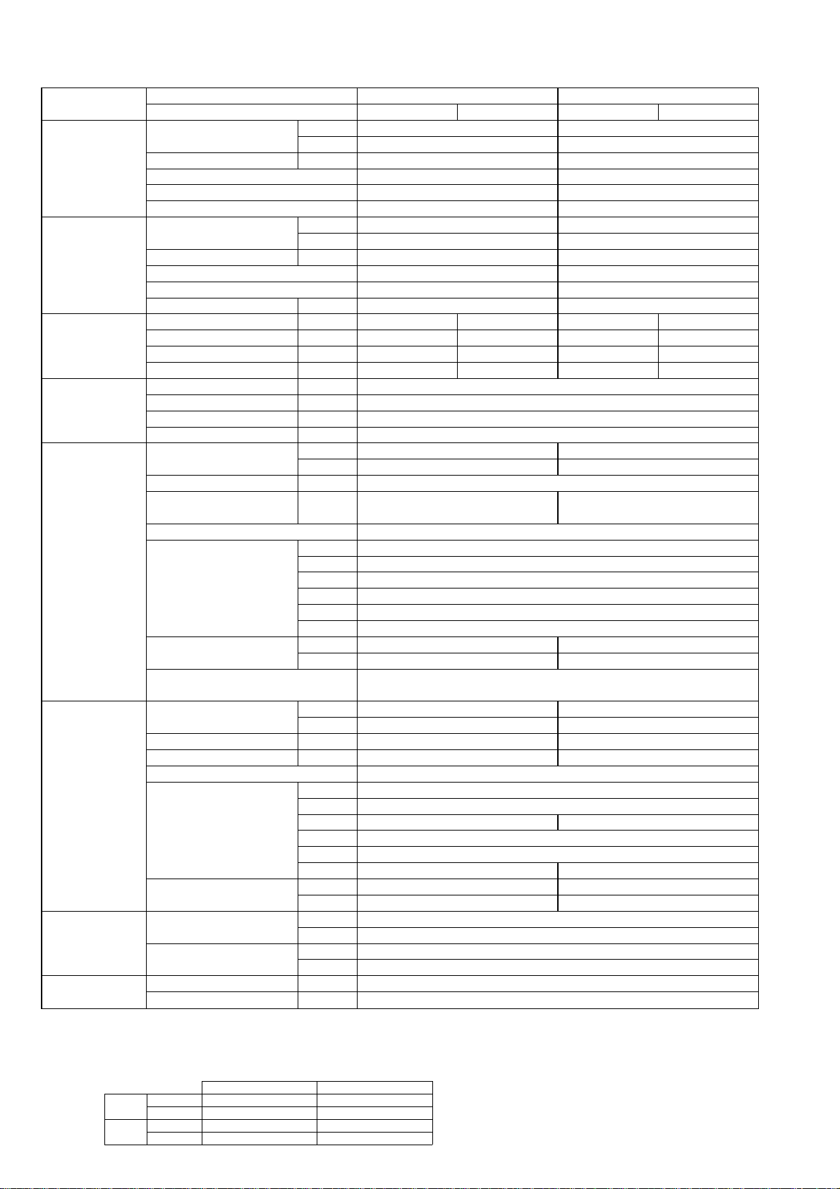
Model name Indoor unit PCA-RP50GA PCA-RP60GA
Outdoor unit H/P PUH-P50VGAA PUH-P50YGAA PUH-P60VGAA PUH-P60YGAA
C/O PU-P50VGAA PU-P50YGAA PU-P60VGAA PU-P60YGAA
Cooling Capacity Btu/h 18,300 22,500
kW 5.35 6.6
Total input kW 2.35 2.62
EER 2.28 2.52
Energy label class F E
SHF 0.72 0.75
Heating * Capacity Btu/h 21,200 24,700
kW 6.2 7.25
Total input kW 2.36 2.66
COP 2.63 2.73
Energy label class E E
Booster heater kW - -
Power supply Phase [ 1313
Cycle Hz 50 50 50 50
Voltage V 230 400 230 400
Breaker size A 25 16 25 16
Indoor unit Air flow CMM 10-11-12-13 14-15-16-18
(Low-Medium2-Medium1-High)
CFM 355-390-425-460 495-530-565-635
External pressure Pa 0 0
Sound level dB(A) 37-38-40-42 37-39-41-43
(Low-Medium2-Medium1-High)
External finish White Munsell 0.70Y 8.59/0.97
Dimension W : mm 1000 1310
D : mm 680
H : mm 210
W : inch 39-3/8 51-9/16
D : inch 26-3/4 26-3/4
H : inch 8-1/4
Weight kg 27 34
lbs 60 75
Unit drain pipe I.D. mm 26
inch 1
Outdoor unit Air flow CMM 55 50
CFM 1,940 1,770
Sound level at cooling dB(A) 48 48
Sound level at heating * dB(A) 50 50
External finish Ivory Munsell 5Y 7/1 Ivory Munsell 5Y 7/1
Dimension W : mm 900 900
D : mm 330+20 330+20
H : mm 855 855
W : inch 35-7/16 35-7/16
D : inch 13 + 3/4 13 + 3/4
H : inch 33-5/8 33-5/8
Weight kg 74 79
lbs 163 174
Refrigerant pipe Gas side O.D. mm 15.88 15.88
size inch 5/8 5/8
Liquid side O.D. mm 9.52 9.52
inch 3/8 3/8
Refrigerant pipe Height difference m Max. 40 Max. 50
length Length m Max. 40 Max. 50
* HEAT PUMP TYPE
NOTE: 1. Rating conditions (ISO T1)
Cooling Indoor : D.B. 27: (80˚F) W.B. 19: (66˚F) Outdoor : D.B. 35: (95˚F) W.B. 24: (75˚F)
Heating Indoor: D.B. 20: (68˚F) Outdoor : D.B. 7: (45˚F) W.B. 6: (43˚F)
Refrigerant piping length (one way) : 5m (16ft.)
2. Guaranteed operating range
Indoor Outdoor
Cooling
Upper limit
D.B. 35˚C, W.B. 22.5˚C
D.B. 46˚C
Lower limit
D.B. 19˚C, W.B. 15˚C D.B. -5˚C
Heating
Upper limit
D.B. 28˚C
D.B. 24˚C, W.B. 18˚C
Lower limit
D.B. 17˚C
D.B. -11˚C, W.B. -12˚C
4. Above data based on indicated voltage
Indoor unit Single phase 230V 50Hz
Single phase 230V 50Hz / 3phase 400V 50Hz
Outdoor unit
3. Guaranteed voltage
198~264V, 50Hz : Single phase
342~457V, 50Hz : 3phase
25
NOTE: 1. Rating conditions (ISO T1)
Cooling Indoor : D.B. 27: (80˚F) W.B. 19: (66˚F) Outdoor : D.B. 35: (95˚F) W.B. 24: (75˚F)
Heating Indoor: D.B. 20: (68˚F) Outdoor : D.B. 7: (45˚F) W.B. 6: (43˚F)
Refrigerant piping length (one way) : 5m (16ft.)
2. Guaranteed operating range
Indoor Outdoor
Cooling
Upper limit
D.B. 35˚C, W.B. 22.5˚C
D.B. 46˚C
Lower limit
D.B. 19˚C, W.B. 15˚C D.B. -5˚C
Heating
Upper limit
D.B. 28˚C
D.B. 24˚C, W.B. 18˚C
Lower limit
D.B. 17˚C
D.B. -11˚C, W.B. -12˚C
4. Above data based on indicated voltage
Indoor unit Single phase 230V 50Hz
Single phase 230V 50Hz / 3phase 400V 50Hz
Outdoor unit
3. Guaranteed voltage
198~264V, 50Hz : Single phase
342~457V, 50Hz : 3phase
Model name Indoor unit PCA-RP71GA PCA-RP100GA
Outdoor unit H/P PUH-P71VGAA PUH-P71YGAA PUH-P100VGAA PUH-P100YGAA
C/O PU-P71VGAA PU-P71YGAA PU-P100VGAA PU-P100YGAA
Cooling Capacity Btu/h 25,400 32,800
kW 7.45 9.6
Total input kW 3.37 3.62
EER 2.21 2.65
Energy label class F D
SHF 0.73 0.76
Heating * Capacity Btu/h 31,200 36,200
kW 9.15 10.6
Total input kW 3.48 3.81
COP 2.63 2.78
Energy label class E E
Booster heater kW - -
Power supply Phase [ 13 1 3
Cycle Hz 50 50 50 50
Voltage V 230 400 230 400
Breaker size A 32 16 32 16
Indoor unit Air flow CMM 14-15-16-18 20-21-23-25
(Low-Medium2-Medium1-High)
CFM 495-530-565-635 705-840-810-885
External pressure Pa 0 0
Sound level dB(A) 37-39-41-43 40-41-43-45
(Low-Medium2-Medium1-High)
External finish White Munsell 0.70Y 8.59/0.97
Dimension W : mm 1310
D : mm 680
H : mm 210 270
W : inch 51-9/16
D : inch 26-3/4
H : inch 8-1/4 10-5/8
Weight kg 34 37
lbs 75 82
Unit drain pipe I.D. mm 26
inch 1
Outdoor unit Air flow CMM 50 85
CFM 1,770 3,000
Sound level at cooling dB(A) 49 51
Sound level at heating * dB(A) 51 53
External finish Ivory Munsell 5Y 7/1 Ivory Munsell 5Y 7/1
Dimension W : mm 900 900
D : mm 330+20 330+20
H : mm 855 1260
W : inch 35-7/16 35-7/16
D : inch 13 + 3/4 13 + 3/4
H : inch 33-5/8 49-5/8
Weight kg 79 97
lbs 174 214
Refrigerant pipe Gas side O.D. mm 15.88 19.05
size inch 5/8 3/4
Liquid side O.D. mm 9.52 9.52
inch 3/8 3/8
Refrigerant pipe Height difference m Max. 50 Max. 50
length Length m Max. 50 Max. 50
* HEAT PUMP TYPE
26
NOTE: 1. Rating conditions (ISO T1)
Cooling Indoor : D.B. 27: (80˚F) W.B. 19: (66˚F) Outdoor : D.B. 35: (95˚F) W.B. 24: (75˚F)
Heating Indoor: D.B. 20: (68˚F) Outdoor : D.B. 7: (45˚F) W.B. 6: (43˚F)
Refrigerant piping length (one way) : 5m (16ft.)
2. Guaranteed operating range
Indoor Outdoor
Cooling
Upper limit
D.B. 35˚C, W.B. 22.5˚C
D.B. 46˚C
Lower limit
D.B. 19˚C, W.B. 15˚C D.B. -5˚C
Heating
Upper limit
D.B. 28˚C
D.B. 24˚C, W.B. 18˚C
Lower limit
D.B. 17˚C
D.B. -11˚C, W.B. -12˚C
4. Above data based on indicated voltage
Indoor unit Single phase 230V 50Hz
Single phase 230V 50Hz / 3phase 400V 50Hz
Outdoor unit
3. Guaranteed voltage
198~264V, 50Hz : Single phase
342~457V, 50Hz : 3phase
Model name Indoor unit PCA-RP125GA PCA-RP140GA
Outdoor unit H/P PUH-P125YGAA PUH-P140YGAA
C/O PU-P125YGAA PU-P140YGAA
Cooling Capacity Btu/h 42,000 48,500
kW 12.3 14.2
Total input kW 4.91 5.89
EER 2.51 2.41
Energy label class E E
SHF 0.77 0.74
Heating * Capacity Btu/h 50,500 58,000
kW 14.8 17.0
Total input kW 5.11 6.24
COP 2.90 2.72
Energy label class D E
Booster heater kW - -
Power supply Phase [ 3
Cycle Hz 50
Voltage V 400
Breaker size A 25
Indoor unit Air flow CMM 27-30-32-34
(Low-Medium2-Medium1-High)
CFM 955-1060-1130-1200
External pressure Pa 0
Sound level dB(A) 41-43-45-46 42-44-46-48
(Low-Medium2-Medium1-High)
External finish White Munsell 0.70Y 8.59/0.97
Dimension W : mm 1620
D : mm 680
H : mm 270
W : inch 63-3/4
D : inch 26-3/4
H : inch 10-5/8
Weight kg 43 45
lbs 95 99
Unit drain pipe I.D. mm 26
inch 1
Outdoor unit Air flow CMM 95 100
CFM 3,360 3,530
Sound level at cooling dB(A) 55 57
Sound level at heating * dB(A) 56 58
External finish Ivory Munsell 5Y 7/1
Dimension W : mm 1050
D : mm 330+20
H : mm 1260
W : inch 41-5/16
D : inch 13 + 3/4
H : inch 49-5/8
Weight kg 125
lbs 276
Refrigerant pipe Gas side O.D. mm 19.05
size inch 3/4
Liquid side O.D. mm 9.52
inch 3/8
Refrigerant pipe Height difference m Max. 50
length Length m Max. 50
* HEAT PUMP TYPE
27
NOTE: 1. Rating conditions (ISO T1)
Cooling Indoor : D.B. 27: (80˚F) W.B. 19: (66˚F) Outdoor : D.B. 35: (95˚F) W.B. 24: (75˚F)
Heating Indoor: D.B. 20: (68˚F) Outdoor : D.B. 7: (45˚F) W.B. 6: (43˚F)
Refrigerant piping length (one way) : 5m (16ft.)
2. Guaranteed operating range
Indoor Outdoor
Cooling
Upper limit
D.B. 35˚C, W.B. 22.5˚C
D.B. 46˚C
Lower limit
D.B. 19˚C, W.B. 15˚C D.B. -5˚C
Heating
Upper limit
D.B. 28˚C
D.B. 24˚C, W.B. 18˚C
Lower limit
D.B. 17˚C
D.B. -11˚C, W.B. -12˚C
4. Above data based on indicated voltage
Indoor unit Single phase 230V 50Hz
Single phase 230V 50Hz / 3phase 400V 50Hz
Outdoor unit
3. Guaranteed voltage
198~264V, 50Hz : Single phase
342~457V, 50Hz : 3phase
Model name Indoor unit PCA-RP71HA PCA-RP125HA
Outdoor unit H/P PUH-P71VGAA PUH-P71YGAA PUH-P125YGAA
C/O PU-P71VGAA PU-P71YGAA PU-P125YGAA
Cooling Capacity Btu/h 25,600 44,400
kW 7.5 13.0
Total input kW 3.36 4.90
EER 2.23 2.65
Energy label class F D
SHF 0.72 0.72
Heating * Capacity Btu/h 31,400 54,600
kW 9.2 16.0
Total input kW 3.41 4.98
COP 2.70 3.21
Energy label class E C
Booster heater kW - -
Power supply Phase [ 13 3
Cycle Hz 50 50 50
Voltage V 230 400 400
Breaker size A 32 16 25
Indoor unit Air flow CMM 17-19 30-38
(Low-High) CFM 600-670 1060-1350
External pressure Pa 0 0
Sound level dB(A) 34-38 44-50
(Low-High)
External finish Stainless steel
Dimension W : mm 1136 1520
D : mm 650
H : mm 280
W : inch 44-3/4 59-7/8
D : inch 25-5/8
H : inch 11
Weight kg 41 56
lbs 90 124
Unit drain pipe I.D. mm 26
inch 1
Outdoor unit Air flow CMM 50 95
CFM 1,770 3,360
Sound level at cooling dB(A) 49 55
Sound level at heating * dB(A) 51 56
External finish Ivory Munsell 5Y 7/1
Dimension W : mm 900 1050
D : mm 330+20 330+20
H : mm 855 1260
W : inch 35-7/16 41-5/16
D : inch 13 + 3/4 13 + 3/4
H : inch 33-5/8 49-5/8
Weight kg 79 125
lbs 174 276
Refrigerant pipe Gas side O.D. mm 15.88 19.05
size inch 5/8 3/4
Liquid side O.D. mm 9.52 9.52
inch 3/8 3/8
Refrigerant pipe Height difference m Max. 50 Max. 50
length Length m Max. 50 Max. 50
* HEAT PUMP TYPE
28

NOTE: 1. Rating conditions (ISO T1)
Cooling Indoor : D.B. 27: (80˚F) W.B. 19: (66˚F) Outdoor : D.B. 35: (95˚F) W.B. 24: (75˚F)
Heating Indoor: D.B. 20: (68˚F) Outdoor : D.B. 7: (45˚F) W.B. 6: (43˚F)
Refrigerant piping length (one way) : 5m (16ft.)
2. Guaranteed operating range
Indoor Outdoor
Cooling
Upper limit
D.B. 35˚C, W.B. 22.5˚C
D.B. 46˚C
Lower limit
D.B. 19˚C, W.B. 15˚C D.B. -5˚C
Heating
Upper limit
D.B. 28˚C
D.B. 24˚C, W.B. 18˚C
Lower limit
D.B. 17˚C
D.B. -11˚C, W.B. -12˚C
4. Above data based on indicated voltage
Indoor unit Single phase 230V 50Hz
Single phase 230V 50Hz / 3phase 400V 50Hz
Outdoor unit
3. Guaranteed voltage
198~264V, 50Hz : Single phase
342~457V, 50Hz : 3phase
2-4-2.HEAT PUMP (with HEATER) TYPE
Model name Indoor unit PCH-P50GAH PCH-P60GAH
Outdoor unit PUH-P50VGAA PUH-P50YGAA PUH-P60VGAA PUH-P60YGAA
Cooling Capacity Btu/h 18,300 22,500
kW 5.35 6.6
Total input kW 2.35 2.62
EER 2.28 2.52
Energy label class F E
SHF 0.72 0.75
Heating Capacity Btu/h 21,200 24,700
kW 6.2 7.25
Total input kW 2.36 2.66
COP 2.63 2.73
Energy label class E E
Booster heater kW 1.29 1.93
Power supply Phase [ 1313
Cycle Hz 50 50 50 50
Voltage V 230 400 230 400
Breaker size A 25 16 25 16
Power supply Phase [ 1
for heater Cycle Hz 50
Voltage V 230
Breaker size A 16
Indoor unit Air flow CMM 10-11-12-13 14-15-16-18
(Low-Medium2-Medium1-High)
CFM 355-390-425-460 495-530-565-635
External pressure Pa 0 0
Sound level dB(A) 37-38-40-42 37-39-41-43
(Low-Medium2-Medium1-High)
External finish White Munsell 0.70Y 8.59/0.97
Dimension W : mm 1000 1310
D : mm 680
H : mm 210
W : inch 39-3/8 51-9/16
D : inch 26-3/4 26-3/4
H : inch 8-1/4
Weight kg 28.5 36
lbs 63 79
Unit drain pipe I.D. mm 26
inch 1
Outdoor unit Air flow CMM 55 50
CFM 1,940 1,770
Sound level at cooling dB(A) 48 48
Sound level at heating dB(A) 50 50
External finish Ivory Munsell 5Y 7/1 Ivory Munsell 5Y 7/1
Dimension W : mm 900 900
D : mm 330+20 330+20
H : mm 855 855
W : inch 35-7/16 35-7/16
D : inch 13 + 3/4 13 + 3/4
H : inch 33-5/8 33-5/8
Weight kg 74 79
lbs 163 174
Refrigerant pipe Gas side O.D. mm 15.88 15.88
size inch 5/8 5/8
Liquid side O.D. mm 9.52 9.52
inch 3/8 3/8
Refrigerant pipe Height difference m Max. 40 Max. 50
length Length m Max. 40 Max. 50
29
NOTE: 1. Rating conditions (ISO T1)
Cooling Indoor : D.B. 27: (80˚F) W.B. 19: (66˚F) Outdoor : D.B. 35: (95˚F) W.B. 24: (75˚F)
Heating Indoor: D.B. 20: (68˚F) Outdoor : D.B. 7: (45˚F) W.B. 6: (43˚F)
Refrigerant piping length (one way) : 5m (16ft.)
2. Guaranteed operating range
Indoor Outdoor
Cooling
Upper limit
D.B. 35˚C, W.B. 22.5˚C
D.B. 46˚C
Lower limit
D.B. 19˚C, W.B. 15˚C D.B. -5˚C
Heating
Upper limit
D.B. 28˚C
D.B. 24˚C, W.B. 18˚C
Lower limit
D.B. 17˚C
D.B. -11˚C, W.B. -12˚C
4. Above data based on indicated voltage
Indoor unit Single phase 230V 50Hz
Single phase 230V 50Hz / 3phase 400V 50Hz
Outdoor unit
3. Guaranteed voltage
198~264V, 50Hz : Single phase
342~457V, 50Hz : 3phase
Model name Indoor unit PCH-P71GAH PCH-P100GAH
Outdoor unit PUH-P71VGAA PUH-P71YGAA PUH-P100VGAA PUH-P100YGAA
Cooling Capacity Btu/h 25,400 32,800
kW 7.45 9.6
Total input kW 3.37 3.62
EER 2.21 2.65
Energy label class F D
SHF 0.73 0.76
Heating Capacity Btu/h 31,200 36,200
kW 9.15 10.6
Total input kW 3.48 3.81
COP 2.63 2.78
Energy label class E E
Booster heater kW 1.93 2.48
Power supply Phase [ 1313
Cycle Hz 50 50 50 50
Voltage V 230 400 230 400
Breaker size A 32 16 32 16
Power supply Phase [ 1
for heater Cycle Hz 50
Voltage V 230
Breaker size A 16
Indoor unit Air flow CMM 14-15-16-18 20-21-23-25
(Low-Medium2-Medium1-High)
CFM 495-530-565-635 705-840-810-885
External pressure Pa 0 0
Sound level dB(A) 37-39-41-43 40-41-43-45
(Low-Medium2-Medium1-High)
External finish White Munsell 0.70Y 8.59/0.97
Dimension W : mm 1310
D : mm 680
H : mm 210 270
W : inch 51-9/16
D : inch 26-3/4
H : inch 8-1/4 10-5/8
Weight kg 36 39.5
lbs 79 87
Unit drain pipe I.D. mm 26
inch 1
Outdoor unit Air flow CMM 50 85
CFM 1,770 3,000
Sound level at cooling dB(A) 49 51
Sound level at heating dB(A) 51 53
External finish Ivory Munsell 5Y 7/1 Ivory Munsell 5Y 7/1
Dimension W : mm 900 900
D : mm 330+20 330+20
H : mm 855 1260
W : inch 35-7/16 35-7/16
D : inch 13 + 3/4 13 + 3/4
H : inch 33-5/8 49-5/8
Weight kg 79 97
lbs 174 214
Refrigerant pipe Gas side O.D. mm 15.88 19.05
size inch 5/8 3/4
Liquid side O.D. mm 9.52 9.52
inch 3/8 3/8
Refrigerant pipe Height difference m Max. 50 Max. 50
length Length m Max. 50 Max. 50
30

NOTE: 1. Rating conditions (ISO T1)
Cooling Indoor : D.B. 27: (80˚F) W.B. 19: (66˚F) Outdoor : D.B. 35: (95˚F) W.B. 24: (75˚F)
Heating Indoor: D.B. 20: (68˚F) Outdoor : D.B. 7: (45˚F) W.B. 6: (43˚F)
Refrigerant piping length (one way) : 5m (16ft.)
2. Guaranteed operating range
Indoor Outdoor
Cooling
Upper limit
D.B. 35˚C, W.B. 22.5˚C
D.B. 46˚C
Lower limit
D.B. 19˚C, W.B. 15˚C D.B. -5˚C
Heating
Upper limit
D.B. 28˚C
D.B. 24˚C, W.B. 18˚C
Lower limit
D.B. 17˚C
D.B. -11˚C, W.B. -12˚C
4. Above data based on indicated voltage
Indoor unit Single phase 230V 50Hz
Single phase 230V 50Hz / 3phase 400V 50Hz
Outdoor unit
3. Guaranteed voltage
198~264V, 50Hz : Single phase
342~457V, 50Hz : 3phase
Model name Indoor unit PCH-P125GAH PCH-P140GAH
Outdoor unit PUH-P125YGAA PUH-P140YGAA
Cooling Capacity Btu/h 42,000 48,500
kW 12.3 14.2
Total input kW 4.91 5.89
EER 2.51 2.41
Energy label class E E
SHF 0.77 0.74
Heating Capacity Btu/h 50,500 58,000
kW 14.8 17.0
Total input kW 5.11 6.24
COP 2.90 2.72
Energy label class D E
Booster heater kW 2.76 2.76
Power supply Phase [ 3
Cycle Hz 50
Voltage V 400
Breaker size A 25
Power supply Phase [ 1
for heater Cycle Hz 50
Voltage V 230
Breaker size A 16
Indoor unit Air flow CMM 27-30-32-34
(Low-Medium2-Medium1-High)
CFM 955-1060-1130-1200
External pressure Pa 0
Sound level dB(A) 41-43-45-46 42-44-46-48
(Low-Medium2-Medium1-High)
External finish White Munsell 0.70Y 8.59/0.97
Dimension W : mm 1620
D : mm 680
H : mm 270
W : inch 63-3/4
D : inch 26-3/4
H : inch 10-5/8
Weight kg 46 48
lbs 101 106
Unit drain pipe I.D. mm 26
inch 1
Outdoor unit Air flow CMM 95 100
CFM 3,360 3,530
Sound level at cooling dB(A) 55 57
Sound level at heating dB(A) 56 58
External finish Ivory Munsell 5Y 7/1
Dimension W : mm 1050
D : mm 330+20
H : mm 1260
W : inch 41-5/16
D : inch 13 + 3/4
H : inch 49-5/8
Weight kg 125
lbs 276
Refrigerant pipe Gas side O.D. mm 19.05
size inch 3/4
Liquid side O.D. mm 9.52
inch 3/8
Refrigerant pipe Height difference m Max. 50
length Length m Max. 50
31

NOTE: 1. Rating conditions (ISO T1)
Cooling Indoor : D.B. 27: (80˚F) W.B. 19: (66˚F) Outdoor : D.B. 35: (95˚F) W.B. 24: (75˚F)
Heating Indoor: D.B. 20: (68˚F) Outdoor : D.B. 7: (45˚F) W.B. 6: (43˚F)
Refrigerant piping length (one way) : 5m (16ft.)
2. Guaranteed operating range
Indoor Outdoor
Cooling
Upper limit
D.B. 35˚C, W.B. 22.5˚C
D.B. 46˚C
Lower limit
D.B. 19˚C, W.B. 15˚C D.B. -5˚C
Heating
Upper limit
D.B. 28˚C
D.B. 24˚C, W.B. 18˚C
Lower limit
D.B. 17˚C
D.B. -11˚C, W.B. -12˚C
4. Above data based on indicated voltage
Indoor unit Single phase 230V 50Hz
Single phase 230V 50Hz / 3phase 400V 50Hz
Outdoor unit
3. Guaranteed voltage
198~264V, 50Hz : Single phase
342~457V, 50Hz : 3phase
2-5. FLOOR STANDING TYPE
2-5-1.HEAT PUMP (without HEATER) AND COOLING ONLY TYPE
Model name Indoor unit PSA-RP71GA PSA-RP100GA
Outdoor unit H/P PUH-P71VGAA PUH-P71YGAA PUH-P100VGAA PUH-P100YGAA
C/O PU-P71VGAA PU-P71YGAA PU-P100VGAA PU-P100YGAA
Cooling Capacity Btu/h 25,900 32,800
kW 7.6 9.6
Total input kW 3.39 3.75
EER 2.24 2.56
Energy label class F E
SHF 0.72 0.72
Heating * Capacity Btu/h 31,600 36,700
kW 9.25 10.75
Total input kW 3.47 3.86
COP 2.67 2.78
Energy label class E E
Booster heater kW - -
Power supply Phase [ 1313
Cycle Hz 50 50 50 50
Voltage V 230 400 230 400
Breaker size A 32 16 32 16
Indoor unit Air flow CMM 15-18 24-31
(Low-High) CFM 530-635 850-1060
External pressure Pa 0
Sound level dB(A) 40-45 44-49
(Low-High)
External finish White Munsell 0.70Y 8.59/0.97
Dimension W : mm 600
D : mm 270 350
H : mm 1900
W : inch 23-5/8
D : inch 10-5/8 13-3/4
H : inch 74-13/16
Weight kg 43 51
lbs 98 112
Unit drain pipeO.D. mm 20
inch 13/16
Outdoor unit Air flow CMM 50 85
CFM 1,770 3,000
Sound level at cooling dB(A) 49 51
Sound level at heating * dB(A) 51 53
External finish Ivory Munsell 5Y 7/1 Ivory Munsell 5Y 7/1
Dimension W : mm 900 900
D : mm 330+20 330+20
H : mm 855 1260
W : inch 35-7/16 35-7/16
D : inch 13 + 3/4 13 + 3/4
H : inch 33-5/8 49-5/8
Weight kg 79 97
lbs 174 214
Refrigerant pipe Gas side O.D. mm 15.88 19.05
size inch 5/8 3/4
Liquid side O.D. mm 9.52 9.52
inch 3/8 3/8
Refrigerant pipe Height difference m Max. 50 Max. 50
length Length m Max. 50 Max. 50
* HEAT PUMP TYPE
32

NOTE: 1. Rating conditions (ISO T1)
Cooling Indoor : D.B. 27: (80˚F) W.B. 19: (66˚F) Outdoor : D.B. 35: (95˚F) W.B. 24: (75˚F)
Heating Indoor: D.B. 20: (68˚F) Outdoor : D.B. 7: (45˚F) W.B. 6: (43˚F)
Refrigerant piping length (one way) : 5m (16ft.)
2. Guaranteed operating range
Indoor Outdoor
Cooling
Upper limit
D.B. 35˚C, W.B. 22.5˚C
D.B. 46˚C
Lower limit
D.B. 19˚C, W.B. 15˚C D.B. -5˚C
Heating
Upper limit
D.B. 28˚C
D.B. 24˚C, W.B. 18˚C
Lower limit
D.B. 17˚C
D.B. -11˚C, W.B. -12˚C
4. Above data based on indicated voltage
Indoor unit Single phase 230V 50Hz
Single phase 230V 50Hz / 3phase 400V 50Hz
Outdoor unit
3. Guaranteed voltage
198~264V, 50Hz : Single phase
342~457V, 50Hz : 3phase
Model name Indoor unit PSA-RP125GA PSA-RP140GA
Outdoor unit H/P PUH-P125YGAA PUH-P140YGAA
C/O PU-P125YGAA PU-P140YGAA
Cooling Capacity Btu/h 42,000 47,400
kW 12.3 13.9
Total input kW 5.03 5.76
EER 2.45 2.41
Energy label class E E
SHF 0.74 0.69
Heating * Capacity Btu/h 49,500 58,000
kW 14.5 17.0
Total input kW 5.32 6.08
COP 2.73 2.80
Energy label class E E
Booster heater kW - -
Power supply Phase [ 3
Cycle Hz 50
Voltage V 400
Breaker size A 25
Indoor unit Air flow CMM 26-33 27-35
(Low-High) CFM 920-1165 955-1240
External pressure Pa 0
Sound level dB(A) 46-51 47-52
(Low-High)
External finish White Munsell 0.70Y 8.59/0.97
Dimension W : mm 600
D : mm 350
H : mm 1900
W : inch 23-5/8
D : inch 13-3/4
H : inch 74-13/16
Weight kg 51 53
lbs 112 117
Unit drain pipeO.D. mm 26
inch 1
Outdoor unit Air flow CMM 95 100
CFM 3,360 3,530
Sound level at cooling dB(A) 55 57
Sound level at heating * dB(A) 56 58
External finish Ivory Munsell 5Y 7/1
Dimension W : mm 1050
D : mm 330+20
H : mm 1260
W : inch 41-5/16
D : inch 13 + 3/4
H : inch 49-5/8
Weight kg 125
lbs 276
Refrigerant pipe Gas side O.D. mm 19.05
size inch 3/4
Liquid side O.D. mm 9.52
inch 3/8
Refrigerant pipe Height difference m Max. 50
length Length m Max. 50
* HEAT PUMP TYPE
33
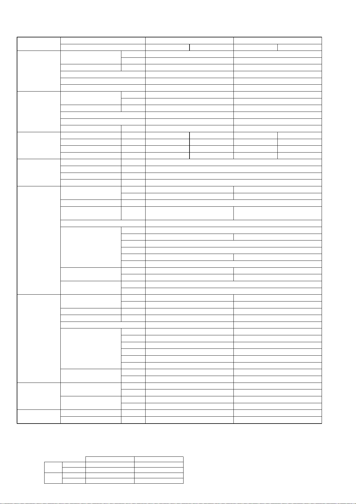
NOTE: 1. Rating conditions (ISO T1)
Cooling Indoor : D.B. 27: (80˚F) W.B. 19: (66˚F) Outdoor : D.B. 35: (95˚F) W.B. 24: (75˚F)
Heating Indoor: D.B. 20: (68˚F) Outdoor : D.B. 7: (45˚F) W.B. 6: (43˚F)
Refrigerant piping length (one way) : 5m (16ft.)
2. Guaranteed operating range
Indoor Outdoor
Cooling
Upper limit
D.B. 35˚C, W.B. 22.5˚C
D.B. 46˚C
Lower limit
D.B. 19˚C, W.B. 15˚C D.B. -5˚C
Heating
Upper limit
D.B. 28˚C
D.B. 24˚C, W.B. 18˚C
Lower limit
D.B. 17˚C
D.B. -11˚C, W.B. -12˚C
4. Above data based on indicated voltage
Indoor unit Single phase 230V 50Hz
Single phase 230V 50Hz / 3phase 400V 50Hz
Outdoor unit
3. Guaranteed voltage
198~264V, 50Hz : Single phase
342~457V, 50Hz : 3phase
2-5-2.HEAT PUMP (with HEATER) TYPE
Model name Indoor unit PSH-P71GAH PSH-P100GAH
Outdoor unit PUH-P71VGAA PUH-P71YGAA PUH-P100VGAA PUH-P100YGAA
Cooling Capacity Btu/h 25,900 32,800
kW 7.6 9.6
Total input kW 3.39 3.75
EER 2.24 2.56
Energy label class FE
SHF 0.72 0.72
Heating Capacity Btu/h 31,600 36,700
kW 9.25 10.75
Total input kW 3.47 3.86
COP 2.67 2.78
Energy label class EE
Booster heater kW 1.93 2.48
Power supply Phase [ 1313
Cycle Hz 50 50 50 50
Voltage V 230 400 230 400
Breaker size A32163216
Power supply Phase [ 1
for heater Cycle Hz 50
Voltage V 230
Breaker size A16
Indoor unit Air flow CMM 15-18 24-31
(Low-High) CFM 530-635 850-1060
External pressure Pa 0
Sound level dB(A) 40-45 44-49
(Low-High)
External finish White Munsell 0.70Y 8.59/0.97
Dimension W : mm 600
D : mm 270 350
H : mm 1900
W : inch 23-5/8
D : inch 10-5/8 13-3/4
H : inch 74-13/16
Weight kg 45 53
lbs 99 117
Unit drain pipeO.D. mm 20
inch 13/16
Outdoor unit Air flow CMM 50 85
CFM 1,770 3,000
Sound level at cooling dB(A) 49 51
Sound level at heating dB(A) 51 53
External finish Ivory Munsell 5Y 7/1 Ivory Munsell 5Y 7/1
Dimension W : mm 900 900
D : mm 330+20 330+20
H : mm 855 1260
W : inch 35-7/16 35-7/16
D : inch 13 + 3/4 13 + 3/4
H : inch 33-5/8 49-5/8
Weight kg 79 97
lbs 174 214
Refrigerant pipe Gas side O.D. mm 15.88 19.05
size inch 5/8 3/4
Liquid side O.D. mm 9.52 9.52
inch 3/8 3/8
Refrigerant pipe Height difference m Max. 50 Max. 50
length Length m Max. 50 Max. 50
34

NOTE: 1. Rating conditions (ISO T1)
Cooling Indoor : D.B. 27: (80˚F) W.B. 19: (66˚F) Outdoor : D.B. 35: (95˚F) W.B. 24: (75˚F)
Heating Indoor: D.B. 20: (68˚F) Outdoor : D.B. 7: (45˚F) W.B. 6: (43˚F)
Refrigerant piping length (one way) : 5m (16ft.)
2. Guaranteed operating range
Indoor Outdoor
Cooling
Upper limit
D.B. 35˚C, W.B. 22.5˚C
D.B. 46˚C
Lower limit
D.B. 19˚C, W.B. 15˚C D.B. -5˚C
Heating
Upper limit
D.B. 28˚C
D.B. 24˚C, W.B. 18˚C
Lower limit
D.B. 17˚C
D.B. -11˚C, W.B. -12˚C
4. Above data based on indicated voltage
Indoor unit Single phase 230V 50Hz
Single phase 230V 50Hz / 3phase 400V 50Hz
Outdoor unit
3. Guaranteed voltage
198~264V, 50Hz : Single phase
342~457V, 50Hz : 3phase
Model name Indoor unit PSH-P125GAH PSH-P140GAH
Outdoor unit PUH-P125YGAA PUH-P140YGAA
Cooling Capacity Btu/h 42,000 47,400
kW 12.3 13.9
Total input kW 5.03 5.76
EER 2.45 2.41
Energy label class E E
SHF 0.74 0.69
Heating Capacity Btu/h 49,500 58,000
kW 14.5 17.0
Total input kW 5.32 6.08
COP 2.73 2.80
Energy label class E E
Booster heater kW 2.76 2.76
Power supply Phase [ 3
Cycle Hz 50
Voltage V 400
Breaker size A 25
Power supply Phase [ 1
for heater Cycle Hz 50
Voltage V 230
Breaker size A 16
Indoor unit Air flow CMM 26-33 27-35
(Low-High) CFM 920-1165 955-1240
External pressure Pa 0
Sound level dB(A) 46-51 47-52
(Low-High)
External finish White Munsell 0.70Y 8.59/0.97
Dimension W : mm 600
D : mm 350
H : mm 1900
W : inch 23-5/8
D : inch 13-3/4
H : inch 74-13/16
Weight kg 53 55
lbs 117 121
Unit drain pipeO.D. mm 26
inch 1
Outdoor unit Air flow CMM 95 100
CFM 3,360 3,530
Sound level at cooling dB(A) 55 57
Sound level at heating dB(A) 56 58
External finish Ivory Munsell 5Y 7/1
Dimension W : mm 1050
D : mm 330+20
H : mm 1260
W : inch 41-5/16
D : inch 13 + 3/4
H : inch 49-5/8
Weight kg 125
lbs 276
Refrigerant pipe Gas side O.D. mm 19.05
size inch 3/4
Liquid side O.D. mm 9.52
inch 3/8
Refrigerant pipe Height difference m Max. 50
length Length m Max. 50
35

3
PLH-P35,50,60,71AAH
PLA-RP35,50,60,71AA
Models
PLA-RP100,125,140AA
PLH-P100,125,140AAH
241
281
A
258
298
B
80
84
C
Receiver
Operation lamp
DEFROST/STAND BY lamp
Emergency operation switch (cooling)
A
(WIRELESS PANEL)
Emergency operation switch (heating)
Branch duct hole
(Cut out hole)
{175
{150
14 - {2.8
Burring hole
350
90
70
_
100 100 90
100
130
155
167
Suspension bolt pitch
Ceiling hole
Branch
duct hole
Suspension bolt pitch
Ceiling hole
840
197 159
159
605
159192
98
89
C
840
860 - 91020 - 45 20 - 45
20 - 4520 - 45
Fresh air intake
Branch duct hole
860 - 910
810
159
16
Terminal block
Drain pipe
VP-25connection
(O.D.{32)
Ceiling surface
Power line entry
Suspension bolt lower edge
Suspension bolt M10
or W3/8
Control wire entry
Feeding hole
(Drain pump)
37428660
17
+5
0
30
190
170
140
50 - 70
105
A
B
1
2
High efficiency filter
& Fresh air intake casement (option)
17
+5
0
135
Air outlet hole
Vane motor
Auto vane
Drain hole
Grille
Air outlet hole
Air intake hole
411
Air intake hole
Air intake grille
577
77 51
M
M
M
A
M
950
51 77
950
577
411
RP35, 50
Use the current nuts meeting the pipe size of the outdoor unit.
Available pipe size
Factory flare nut attachment to the heat-exchanger.
1 LIQUID SIDE
2 GAS SIDE
RP60 RP71
[6.35 [6.35 — —
[9.52 [9.52 [9.52 [9.52
[12.7 — — —
[15.88 [15.88 [15.88 [15.88
———[19.05
RP100, 125, 140
P35,50,60,71
——
[9.52 [9.52
——
[15.88 —
— [19.05
P100, 125, 140
Detail drawing of fresh air intake
3 - {2.8
Burring hole
{125
Burring hole pitch
{100
(Cut out hole)
Ceiling surface
120
_
120_
158
OUTLINES AND DIMENSIONS
INDOOR UNIT
Unit : mm
PLA-RP35AA PLA-RP50AA PLA-RP60AA PLA-RP71AA PLA-RP100AA PLA-RP125AA
PLA-RP140AA
PLH-P35AAH PLH-P50AAH PLH-P60AAH PLH-P71AAH PLH-P100AAH PLH-P125AAH
PLH-P140AAH
36

PMH-P25BA PMH-P35BA PMH-P50BA
PMH-P50BA
PMH-P35BA
O.D.{35
PMH-P25BA
O.D.{6.35(1/4") O.D.{9.52(3/8")
PVC pipe:VP-20[O.D.{25(1")]
O.D.{12.7(1/2") O.D.{15.88(5/8")
4-{2.8 Burring hole
100
{
90-
122
{
250 288.5
Unit : mm
108
110
mounting plate
Flesh air intake hole
235 or more
230
110
Details of fresh air intake hole
Gas pipe
Liquid pipe
pipe cover
Drainage piping
Refrigerant
piping
74.5
26
20
75926
960 seiling opening20 20
1000 outer side of grille
811 suspension bolt pitch74.5
20
247
69
53
17.517.5
Knock out
outer line of grille
center of unit
812
Air outlet(lower)
Terminal block for
indoor/outdoor connection
elect box
759
{50
Right side
Terminal block for remote controller
suspension bolt(M10 or W3/8)
Installation space required around indoor unit
200600200
drain pan
Panel(grille):PMP-40BM
30
470 outer side of grille
60 40
Panel(grille):PMP-40BM
(56)
Front
43
46
2828
45
20
Top
45
20
340 suspension bolt pitch
430 ceiling opening
470 outer side of grille
302
395
Refrigerant pipe(gas)
Drainage pipe
PVC pipe:VP-20[O.D.{25]
141
254
230
198
176
(20)
(10)
96
Refrigerant
(96)
pipe(liquid)
1000 outer side of grille
Left side
ceiling panel
ceiling
panel
same line
drain pan
Lower view
37

PEAD-RP35EA PEAD-RP50EA PEAD-RP60EA
2
1
3
4
5
6
7
Refrigerant piping flare connection (liquid [ F copper tube):HP
Refrigerant piping flare connection (gas [G copper tube):LP
Drain R1(External thread)
Electrical parts box
Drain Pump (Option)
Drain Pipe (Option) ... Flexible joint VP-25(I.D.
[
32)
Filter
R407C Outdoor unit : 9.52
F
R410A Outdoor unit : 6.35 w
R407C Outdoor unit : 9.52 w
Outdoor unit (SUZ) : 6.35
EDCBA
804830
-
305772
Model
RP60
R407C Outdoor unit : 15.88
G
R410A Outdoor unit : 12.7 w
15.88
104410702902801012
RP35,50
w Setting at shipment
2
1
3
4
Air inlet
Air outlet
Access door
55
50~150
81
197
Service space:500 or more
Keep duct-work length 850mm or more.
Be sure to apply the air filter
near the air inlet grille.
5
6
75
44
18
365~465
B 81
10
56 355
7
159
243
Air outlet
Air inlet
7
Lifting bolt hole
(14×22)
10- [3 (RP35,50)
12-
[
3 (RP60)
In case of rear inlet
In case of bottom inlet
10- [3 (RP35,50)
12-
[
3 (RP60)
D
30
C
10
81BC
A
450
450
10- [3 (RP35,50)
12-
[
3 (RP60)
176
40
288
256
3.5
3.5
10
109
179
10
35
24
30640
30
21
277
80
45
282
13
13E
A
61 227
29
85
40
176
10
15
3.5
256
BC 81
10
81
A
Set
R407C outdoor unit : 19.05158416104704601552RP140
15.8810441070290
F
R410A Outdoor unit : 15.88 w
EDCBA
12841310370360
2801012
1252
Model
RP100,125
RP71
w
Setting at shipment
7
44
243
308
323
75
6
5
13
Refrigerant piping flare connection (liquid [9.52 copper tube):HP
Refrigerant piping flare connection (gas [F copper tube):LP
Drain R1 (External thread)
Electrical parts box
Drain Pump (Option)
Drain Pipe (Option) ... Flexible joint VP25(I.D.[32)
Filter
Service space:500 or more
81
365~465
197
81
50~150
55
29
Access door
Air outlet
Air inlet
4
3
1
2
7
6
5
4
3
2
1
113
307
122
12-[3
(14x22)
Lifting bolt hole
45
Set
210
12-[3
450
450
140
282
680
3.5
3.5
30
319
261
181
40
30
A
C B
81
10
375
10
80
C B 81
A
E 13
30D
20
35
30
1053 169
Keep duct-work length 850mm or more.
Be sure to apply the air filter
near the air inlet grille.
Unit : mm
PEAD-RP71EA PEAD-RP100EA PEAD-RP125EA PEAD-RP140EA
38

8
Air inlet
Air outlet
243
159
8
8
35556
10
81B
365~465
18
44 75
7
6
7
5
6
5
4
3
2
1
Refrigerant piping flare connection (liquid [9.52 copper tube):HP
Refrigerant piping flare connection (gas [15.88 copper tube):LP
Drain R1(External thread)
Electrical parts box
Electric Heater
Drain Pump (Option)
Drain Pipe (Option) ••• Flexible joint VP-25(I.D.[32)
Filter
Keep duct-work length 850mm or more.
Be sure to apply the air filter (field supply) near the air inlet grille.
Service space:500 or more
197
81
50~150
55
Access door
Air outlet
Air inlet
4
3
1
2
10-[3(P35, 50)
12-[3(P60)
In case of bottom inlet
In case of rear inlet
10-[3(P35, 50)
12-[3(P60)
(14o22)
Lifting bolt hole
A
81
10
81C B
256
15
10
17640
85
29
22761
A
E 13
13
282
45 80
277
21
30
640 30
24
35
10
179
109
10
3.5
3.5
256
288
40176
Set
10-[3(P35, 50)
12-[3(P60)
450
450
A
C B 81
10
C
30D
804830-
EDCBA
10441070290280
305772
1012
Model
P60
P35,50
19.05158416104704601552P140
15.8810441070290
F
19.05
EDCBA
12841310370360
2801012
1252
Model
P100,125
P71
8
44
243
308
323
75
7
6
5
13
Refrigerant piping flare connection (liquid [9.52 copper tube):HP
Refrigerant piping flare connection (gas
[F copper tube):LP
Drain
R1(External thread)
Electrical parts box
Electric Heater
Drain Pump (Option)
Drain Pipe (Option) ••• Flexible joint VP25(I.D.
[32)
Filter
Keep duct-work length 850mm or more.
Be sure to apply the air filter (field supply) near the air inlet grille.
Service space:500 or more
81
365~465
197
81
50~150
55
Access door
Air outlet
Air inlet
4
3
1
2
8
7
6
5
4
3
2
1
113
307
122
12-[3
(14
O22)
Lifting bolt hole
45
Set
210
12-[3
450
450
140
282
680
3.5 3.5
30
319
261
181 40
30
A
C B 81
10
375
10
80
C B 81
A
E 13
30D
20
35
30
1053 169
29
PEHD-P35EAH PEHD-P50EAH PEHD-P60EAH
Unit : mm
PEHD-P71EAH PEHD-P100EAH PEHD-P125EAH PEHD-P140EAH
39

PEAD-RP60GA
Model
ABCDE
7
7
9
8
9.52
9.52
15.88
15.88
8
10
FG H J
RP60
RP71
RP100
1125
1125
1365
1090
1090
1330
1050
1050
1290
1012
1012
1252
840
840
1080
Outdoor unit(SUZ) : 6.35
Other outdoor unit : 9.52 w
R410A Outdoor unit : 15.88 w
R407C Outdoor unit : 19.05
w Setting at shipment
PEAD-RP71GA
PEAD-RP100GA
Unit : mm
40

PKA-RP35GAL PKA-RP50GAL
BYOFF
ON STAND
HEATCOOL
OFF BY
ON STAND
COOL HEAT
ÅrÇoÇoÅqÅ@ëOñ Å@ÇeÇqÇnÇmÇs ÅrÇoÇoÅqÅ@ëOñ Å@ÇeÇqÇnÇmÇs
r.SLI.SLI
m m
MITSUBISHI ELECTRICMITSUBISHI ELECTRIC
r.S.S
L
I
m m
MITSUBISHI ELECTRICMITSUBISHI ELECTRIC
Knock out hole for right piping
Refrigerant pipe.Drain pipe.
Wiring hole
21
Right side
Less than 15
70
245
60
235
Auto vane
Front view
Air intake
Air intake
Air intake
Air intake
198
53
340
715 225
340 80 280 233
990
21
Left side
Knock out hole for left piping
Refrigerant pipe.Drain pipe.Wiring hole.
60
70
245
(Necessary clearance for
Unit installation)
Right side
Allowing clearances
Front view
Less than 130
50 or more 150 or more
180 or more 30 or more
for bolts
Left-rear
piping hole
left-rear piping
R52.5
R52.5
Installation plate
balance point hole
Details of installation plate
49-[5hole
for tapping screw
Knock out hole for
right-rear piping
Right-rear
piping hole
Unit center
14-[14hole
Knock out hole for
425
420
170
190
210
230
0
322
0355580130
190
230
272
310
0
35
95
150
205
260
320
345
495
20
75
135
190
245
300
360
405
495
32
0
w1 Sleeves are available on the market.
w2 This size shows the lower end of through hole.
[90~[100[90
Through hole
Sleeve w1
35, 50
Model
R
52.5
R52.5
Gas pipe
Liquid pipe
Terminal block for
Terminal block to
outdoor unit
Filter grip
Service panel
(Power supply access)
(Flexible hose total length800)
(Right side piping
installation)
(Left side piping
installation)
Unit drain pipe O.D.20
Front view(to open the grille)
700
449
86
581 54
31 280
35
Knock out hole for under piping
Refrigerant piping.Drain pipe.
Wiring hole
12-Louvers(manual)
Air outlet
Lower side
80
50
395400
190
60
70 35
79
160 40
235
705
power supply (Heater (PKH-P35, 50GALH only))
153
GAS SIDE
LIQUID SIDE
RP35, 50
P35, 50
[6.35
[9.52
[12.7
[15.88
—
[9.52—[15.88
Use the current nuts meeting the pipe size of the outdoor unit.
Available pipe size
: Factory flare nut attachment to the heat - exchanger.
PKH-P35GALH PKH-P50GALH
Unit : mm
41
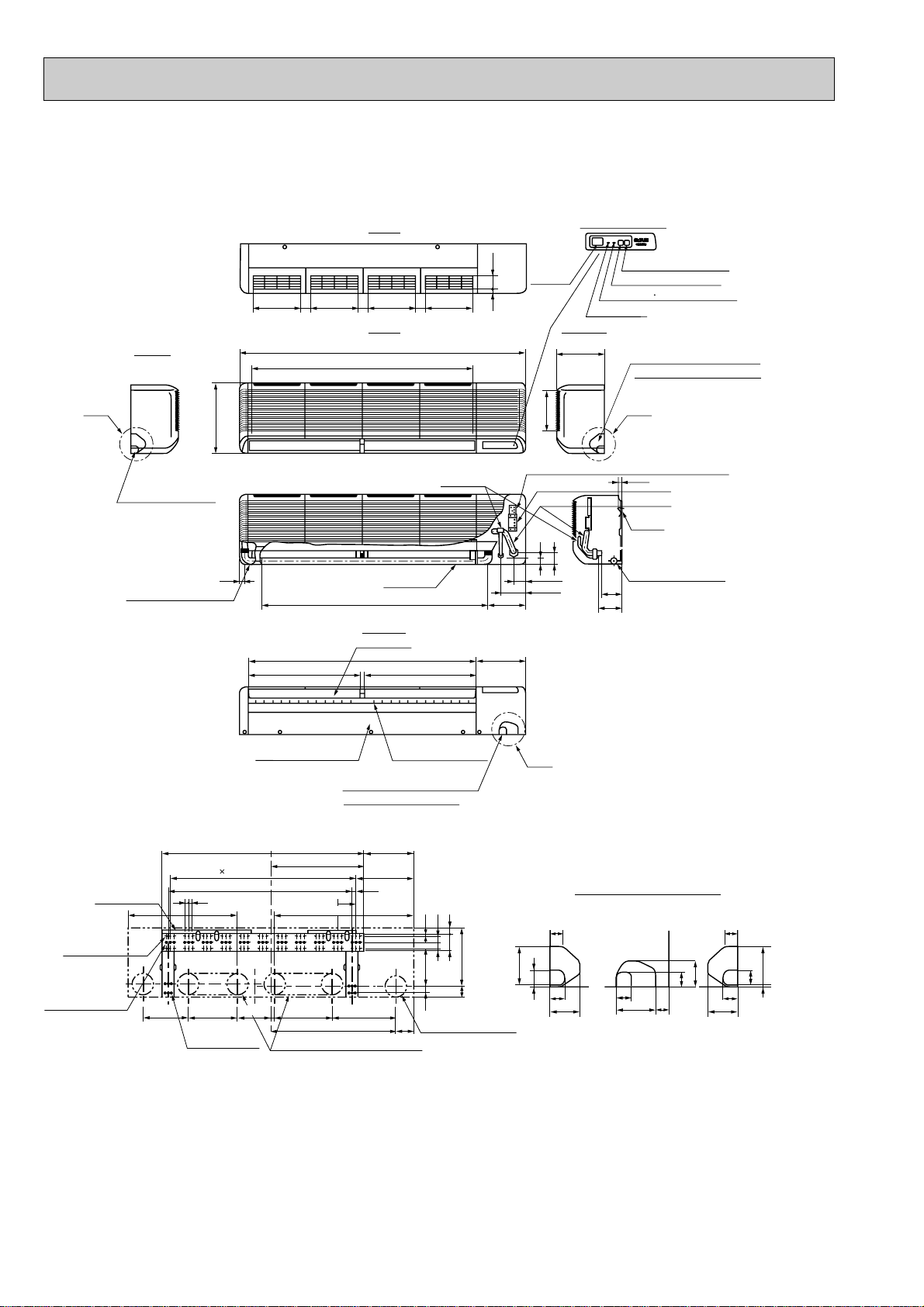
PKA-RP60FAL PKA-RP71FAL
235
45
235
45
235
45
235
62.5
13
58
42
340
197
Top
Front
Right side
Left side
1400
1090
Air intake
235
C
Knock out hole for right piping
Refrigerant pipe. Drain pipe
Knock out hole for
left piping
Drain hose for
left-hand side piping
Drain hose
Lower side
Auto vanes
(Gas pipe)
Drain hose O.D.20
Bolt
Gas pipe
15
(Liquid pipe)
Liquid pipe [9.52(3/8F)
Gas pipe [15.88(5/8F)
Liquid pipe
A
30
32
39
98
37
74
439
100
30
37
74
4
2980
280
3030
18430
60
10
39
37
65
100
AB C
Knock out hole for wiring
25
1110
183
240
B
1120
552
55
120
107
111
Air outlet
552
Air outlet
Louvers (manual)
Under panel
Removable at left-hand
side piping
Knock out hole for under-piping
Refrigerant pipe. Drain pipe
Rear piping opening
Range for left rear piping opening
12-ø6 hole for
tapping screw
66-ø6 hole for
tapping screw
Wall fixture
Unit center
32-ø12 hole for bolt
225
18
18
91
900
990
455
285
245
19
240 280 314
610
90
Drainage range
on left-hand side
Drainage range
on right-hand side
10 91=(910)
180
Terminal block for heater (PKH only)
Terminal block for indoor/outdoor connecting line
Display section
Receiving
section
Power lamp
Emergency switch(Heat)
Emergency switch(Cool)
Defrosting Initial heating lamp
PKH-P60FALH PKH-P71FALH
Unit : mm
42

PKA-RP100FAL
235
45
235
45
235
45
235
45
235
62.5
13
58
42
340
197
Top
Front
Right side
Display section
Receiving
section
Power lamp
Emergency switch(Heat)
Emergency switch(Cool)
Defrosting Initial heating lamp
Left side
1680
1370
Air intake
235
C
Knock out hole for right piping
Knock out hole for left piping
Drain hose for left-hand side piping
Drain hose
Drain hose
Lower side
Auto vane
(Gas pipe)
Bolt
Gas pipe
15
(Liquid pipe)
Liquid pipe
A
30
32
39
98
37
74
439
100
30
37
74
4
2980
280
3030
18430
60
10
39
37
65
100
AB C
Knock out hole for wiring
25
1110
183
240
B
1400
55
120
102
111
694
Air outlet
694
Air outlet
Louvers (manual)
Under panel
(Removable at left-hand side piping)
Knock out hole for under-piping
Refrigerant pipe. Drain pipe
Rear piping opening
Range for left rear piping openingRange for left rear piping opening
12-ø6 hole for tapping screw
84-ø6 hole for
tapping screw
Wall fixture
Unit out line
Unit center
41-ø12 hole for bolt
295 225
18
18
91
900
1270
595
285
245
19
240 280 314
750
90
Drainage range
on right-hand side
13 91=(1183)
180
Drainage range
on left-hand side
Terminal block for heater (PKH only)
Terminal block for indoor/outdoor connecting line
Drain hose O.D.20
: Factory flare nut attachment to the
heat-exchanger.
GAS SIDE
LIQUID SIDE
RP100
[9.52
[15.88
[19.05
P100
[9.52
[19.05
Use the current nuts meeting the pipe size
of the outdoor unit.
Available pipe size
PKH-P100FALH
Unit : mm
43

PCA-RP50GA
180
210
157
15
85
182 liquid
201 gas
241 (Drainage)
Air intake
918
161 90
254
680
506 56
Electrical box
226
70
6
2
7
17
150
140
70
320
80
933 (suspension bolt pitch)
983
1000
Air outlet
81
904
76
525
928
352
263
171
138
86
46 175 1
131
38
38
79
161
32
179
42
6~7
Ceiling
Electrical box
[Front view]
When electrical
box is pulled
down
3
2
8
5
1
4
[15.88
[9.52
P50
[15.88
[12.7
[6.35
Available pipe size
[9.52
4 GAS SIDE
5 LIQUID SIDE
RP50
Use the current nuts meeting the pipe size of the outdoor unit.
: Factory flare nut attachment to the heat-exchanger.
PCH-P50GAH
NOTES:
1. Use M10 or W3/8 screws for anchor bolt.
2. When optional drain lift-up mechanism is installed, always provide
upward piping for refrigerant piping.
Unit : mm
1 Drainage pipe connection (26mm I.D.)
2 Drainage pipe connection (for the left arrangement)
3 Knock out hole for left drain-piping arrangement
4 Refrigerant-pipe connection (gas pipe side/flared connection)
5 Refrigerant-pipe connection (liquid pipe side/flared connection)
6 Knock out hole for upper drain pipe arrangement
7 Knock out hole for left drain pipe arrangement
8 Knock out hole for wiring arrangement
44

PCA-RP60GA PCA-RP71GA
161 90
254
680
506 56
1240 (suspension bolt pitch)
140
150
320 80
17
70
6
1290
1214
210
180
81 76
1310
Air outlet
1228
Air intake
85
182
201
241
15
157
(liquid)
(5/8F gas)
(Drainage)
7
2
Electrical box
70
226
3
2
8
5
1
4
Electrical box
When electrical
box is pulled
down
[ Front view ]
Ceiling
32
179
161
38
3879
42
6~7
525
1235
416
263
171
138
86
131
175 1
46
: Factory flare nut attachment to the heat-exchanger.
4 GAS SIDE
5 LIQUID SIDE
Use the current nuts meeting the pipe size of the outdoor unit.
Available pipe size
RP71,P60,P71
RP60
[6.35
[9.52
[15.88
[9.52
[15.88
PCH-P60GAH PCH-P71GAH
NOTES:
1. Use M10 or W3/8 screws for anchor bolt.
2. When optional drain lift-up mechanism is installed, always provide
upward piping for refrigerant piping.
Unit : mm
1 Drainage pipe connection (26mm I.D.)
2 Drainage pipe connection (for the left arrangement)
3 Knock out hole for left drain-piping arrangement
4 Refrigerant-pipe connection (gas pipe side/flared connection)
5 Refrigerant-pipe connection (liquid pipe side/flared connection)
6 Knock out hole for upper drain pipe arrangement
7 Knock out hole for left drain pipe arrangement
8 Knock out hole for wiring arrangement
45

PCA-RP100GA
161 90
254
680
506 56
1228
Air intake
1214
270
207
81 96
1310
Air outlet
1240 (suspension bolt pitch)
140
150
320 80
18
70
6
87
182
198
245
16
217
(3/8F liquid)
(5/8F, 3/4F gas)
(Drainage)
7
2
Electrical box
70
229
3
2
8
5
1
4
Electrical box
When electrical
box is pulled
down
[ Front view ]
Ceiling
93
160
38
38 140
42 239
6~7
525
1235
687
263
171
138
86
192
236
1
45
Use the current nuts meeting the pipe size of the outdoor unit.
:Factory flare nut attachment to the heat-exchanger.
4 GAS SIDE
5
LIQUID SIDE
Available pipe size
RP100
[9.52
[15.88
[19.05
P100
[9.52
[19.05
PCH-P100GAH
NOTES:
1. Use M10 or W3/8 screws for anchor bolt.
2. When optional drain lift-up mechanism is installed, always provide
upward piping for refrigerant piping.
Unit : mm
1 Drainage pipe connection (26mm I.D.)
2 Drainage pipe connection (for the left arrangement)
3 Knock out hole for left drain-piping arrangement
4 Refrigerant-pipe connection (gas pipe side/flared connection)
5 Refrigerant-pipe connection (liquid pipe side/flared connection)
6 Knock out hole for upper drain pipe arrangement
7 Knock out hole for left drain pipe arrangement
8 Knock out hole for wiring arrangement
46
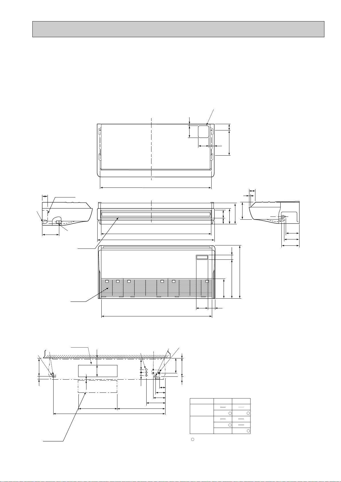
PCA-RP125GA PCA-RP140GA
161 90
254
680
506 56
1535
Air intake
1524
270
207
81 96
1620
Air outlet
1547(suspension bolt pitch)
140
150
320 80
18
70
6
87
182
198
245
16
217
(3/8F liquid)
(5/8F, 3/4F gas)
(Drainage)
7
2
Electrical box
70
229
3
2
8
5
1
4
Electrical box
When electrical
box is pulled
down
[ Front view ]
Ceiling
93
160
38
38 140
42 239
6~7
525
1545
687
263
171
138
86
192
236
1
45
:Factory flare nut attachment to the heat-exchanger.
RP125,140
[19.05
[15.88
[9.52
Use the current nuts meeting the pipe size of the outdoor unit.
4 GAS SIDE
5 LIQUID SIDE
Available pipe size
P125,140
[19.05
[9.52
PCH-P125GAH PCH-P140GAH
NOTES:
1. Use M10 or W3/8 screws for anchor bolt.
2. When optional drain lift-up mechanism is installed, always provide
upward piping for refrigerant piping.
Unit : mm
1 Drainage pipe connection (26mm I.D.)
2 Drainage pipe connection (for the left arrangement)
3 Knock out hole for left drain-piping arrangement
4 Refrigerant-pipe connection (gas pipe side/flared connection)
5 Refrigerant-pipe connection (liquid pipe side/flared connection)
6 Knock out hole for upper drain pipe arrangement
7 Knock out hole for left drain pipe arrangement
8 Knock out hole for wiring arrangement
47
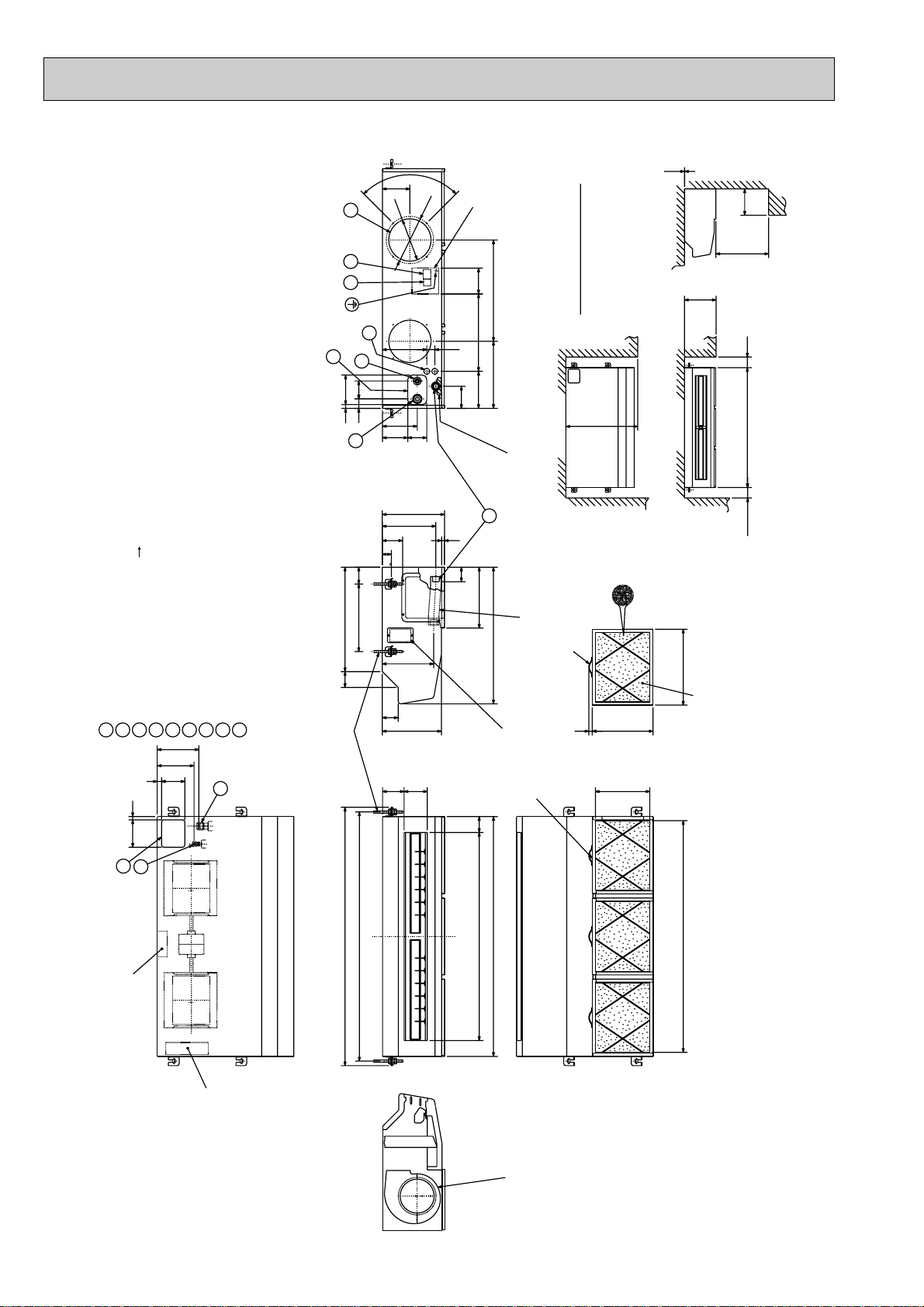
PCA-RP71HA
Unit : mm
(Gap to ceiling)
90˚
130
9
[222
[200
Terminal block box
78
(122)
480
Allowing clearances
6
4
85
14018
45
1
210
2
165
120
90
366
38
318
176
105
650
Less than
Rear wall
Adjustable part
2 ~ 3
300
Ceiling
Less than
Less than
250
1001136
or more
500
or more
295
254
70~90
43
320 80
495
<Suspension bolt pitch>
243
75
Option parts:duct flange( [ 200). model: PAC-SF28OF-E(1 pcs.)
Terminal block(remote controller)
Terminal block(indoor/outdoor connecting line)
Knock out hole for upper refrigerant-pipe arrangement
Flexible hose(accessory) Drainage pipe connection(26mm I.D.)
Refrigerant-pipe connection(gas pipe side/flared connection : 5/8F)
1
Knock out hole for behind refrigerant-piping arrangement
Refrigerant-pipe connection(liquid pipe side/flared connection : 3/8F)
2
3
130 15
5
2
5
4
<gas>
<liquid>
21
Knock out hole for wiring arrangement : 2- [ 27
6
197
175
110
Knock out hole (duct for fresh air intake): 2- [ 200
8
7
9
75
Suspension bolt
280
<Air outlet>
1
3
13
70
289
650
Inspection port
75
<Air outlet>
1224
<Suspension bolt pitch>
1180
986
1136
handle
<Flexible hose(accessory)>
16
288
<Filter contour dimension>
(pipe sensor)
Filter (3-pieces)
258 110 102
or more
100
360
Filter element for the exchange
model:PAC-SG38KF-E (12pcs.)
<Air intake>
1098
<Air intake>
Terminal block box
Electrical box
48
The half bottom of FAN CASING
can be separated.
1.Use M10 or W3/8 screw for anchor bolt.
NOTES.

PCA-RP125HA
(Gap to ceiling)
90˚
[222
[200
9
130
440440298
2~3
250
Less than
or more
500
Unit : mm
78
Terminal block box
(122)246
6
90 120
295
254
243
280
<Air outlet>
110 102
38 210
176
105
Adjustable part
3
13
70
289
650
<Flexible hose(accessory)>
Inspection port
(pipe sensor)
Filter (4-pieces)
4
2
8545
14018
165
1
70~90
43
320 801564
495
<Suspension bolt pitch>
75
Refrigerant-pipe connection(gas pipe side/flared connection : 5/8F, 3/4F)
Flexible hose(accessory) Drainage pipe connection(26mm I.D.)
Refrigerant-pipe connection(liquid pipe side/flared connection : 3/8F)
Knock out hole for behind refrigerant-piping arrangement
Knock out hole for upper refrigerant-pipe arrangement
Knock out hole for wiring arrangement : 2- [ 27
4
3156728
<gas>
197
175
<liquid>
110
21
Knock out hole (duct for fresh air intake) : 2- [ 200
Terminal block(indoor/outdoor connecting line)
Option parts:duct flange( [ 200). model: PAC-SF28OF-E(1 pcs.)
Terminal block(remote controller)
9
1
75
Suspension bolt
300
Allowing clearances
650
Less than
Rear wall
Less than
Ceiling
handle
360
16
288
<Filter contour dimension>
258
<Air intake>
Filter element for the exchange
1001520100
or more
or more
: Factory flare nut attachment to the heat-exchanger
[ 9.52
RP125
[ 15.88
model:PAC-SG38KF-E (12pcs.)
[ 19.05
130 15
5
2
Terminal block box
Electrical box
<Suspension bolt pitch>
1608
<Air outlet>
1370 75
1520
The half bottom of FAN CASING
can be separated.
49
1482
<Air intake>
2 LIQUID SIDE
Available pipe size
1.Use M10 or W3/8 screw for anchor bolt.
NOTES.
1 GAS SIDE
Use the current nuts meeting the pipe size
of the outdoor unit.

PSA-RP71GA
PSH-P71GAH
300 or more
1
5 or more
2
Unit : mm
Front 1,000 or more
Knock out hole
for under-piping
Front side
218
VIEW "A"
95
100
90
175
55 143
Rear side
20
160
Knock out hole
for bottom fixing
277
100 or more 100 or more
40 66
Liquid pipe [9.52(3/8F)
95
Electrical parts box
46122
Terminal block for
indoor/outdoor
connection.
1. Service access allows for
insertion of screw driver.
2. Adjustable
186
Drain pipe
Gas pipe [15.88(5/8F)
47
767
714 123
590
480
110
105
Knock out hole for piping and wiring
(140 80 oval)
20
A
132
Knock out hole
for branch duct
240
Rear side
10
3838
15
111
Knock out hole for
under-piping(120 70 oval)
130
100
125
340
370
Front side
10
270
250
40
50260
Metal fixture
against overturning
520
260
240
2010
130130
controller
766
130 71
Terminal block for
heater power supply
(Only PSH-P•GAH)
1900
50
608
82730
216
115
Knock out hole for
wiring.[27
(Provided on both sides)
180
235
70
Knock out hole for refrigerant and drainage.
90 60 oval (Provided on both sides)
530
600
50

PSA-RP100GA PSA-RP125GA PSA-RP140GA
PSH-P100GAH PSH-P125GAH PSH-P140GAH
5 or more
300 or more
2
1
Unit : mm
Front 1,000 or more
Knock out hole
for under-piping
Front side
218
VIEW "A"
95
Knock out hole for
under-piping(120 70 oval)
[ 9.52
P100,125,140—[ 19.05
[ 9.52
RP100,125,140
[ 15.88
[ 19.05
: Factory flare nut attachment to
LIQUID SIDE
120
GAS SIDE
277
Use the current nuts meeting the pipe size
of the outdoor unit.
Available pipe size
77
201
120
Rear side
20
140
Knock out hole
255
for bottom fixing
the heat-exchanger
Terminal block for
indoor/outdoor
100 or more 100 or more
40 66
Liquid pipe [9.52(3/8F)
95
Electrical parts box
46122
connection.
Terminal block for
heater power supply
(Only PSH-P•GAH)
1. Service access allows for
insertion of screw driver.
2. Adjustable
261
[19.05(3/4F)
Drain pipe
Gas pipe [15.88(5/8F)
47
767
714 123
590
480
110
105
Knock out hole for piping and wiring
(140 80 oval)
20
115
50
Knock out hole for
wiring.[27 (Provided on both sides)
A
132
Knock out hole
for branch duct
240
Rear side
10
3838
15
111
260
350
330
40
130
100
125
340
370
Front side
10
50260
Metal fixture
against overturning
520
260
240
2010
130130
controller
766
130 71
1900
608
82730
216
315
70
Knock out hole for refrigerant and drainage.
90 60 oval (Provided on both sides)
530
600
51

OUTDOOR UNIT
321
T
SR
w1 248
w1 196
500
Power Supply Wiring Hole
(2-[27Knock-Out)
Right Piping Hole
(Knock-Out)
Power Supply Wiring Hole
(2-[27Knock-Out)
Terminal Connections
Left...Power supply Wiring
Right..Indoor/Outdoor Wiring
70
70
15515515510930
21585
Bottom Piping Hole
(Knock-Out)
Drain Hole
(5-[33holes)
18
18
424
900
318
Handle for moving
Earth Point
Service Panel
Front Piping Cover
Rear Piping Cover
1
2
Side Air
Intake
200200
53
370
(14)
412
29
330
55
4351
Rear Air Intake
Air Discharge
2-U Shaped notched holes
(Foundation Bolt M10)
2-12x40 oval holes
(Foundation Bolt M10)
20
28
58
Installation Feet
Rear
Air
Intake
Side
Air
Intake
Handle for
moving
3
230220220230
637
650
3030
Rear Trunking Hole
(Knock-Out)
< Rear Side >
Power Supply Wiring Hole
(2-[27Knock-Out)
40
33
22 55
68 63
65
92
Rear Piping Hole
(Knock-Out)
[
92
Piping Knock-Out Hole Details
. .
Refrigerant GAS pipe connection (FLARE)P35V(Y)GAA: [15.88 (5/8F)
. .
Refrigerant LIQUID pipe connection (FLARE)P35V(Y)GAA: [9.52 (3/8F)
. .
Height of STOP VALVE connection location.
1
2
Front Trunking Hole
(Knock-Out)
< Right Side >< Front Side >
Explanation of Notes
40
68 63
22 55
65
92
33
27
100
50
50
100
33
[92
Front Piping Hole
(Knock-Out)
5540
3
. .
3-[3.6 holes (for securing the top of the unit)
These holes are provided for cases where the unit must
be secured by the base AND by the top surface.
Use Self Tapping screws 5 x L15 or less.(Obtained locally)
w1
. .
Refrigerant GAS pipe connection (FLARE)P25VGAA : [12.7 (1/2F)
. .
Refrigerant LIQUID pipe connection (FLARE)P25VGAA : [6.35 (1/4F)
1
2
O
ve
r 10m
m
FRE
E
O
ver 500m
m
Less than
30mm
FREE SPACE (Around the Unit)
Piping and wiring connections
can be made from 4 directions:
Front, Right, Rear and Below.
FOUNDATION BOLTS
1
The diagram below shows a
basic example.
Explanation of particular details are
given in the installation manuals etc.
SERVICE SPACE
Dimensions of space needed
for service access are
shown in the below diagram.
2
Over500
Over500
PIPING-WIRING DIRECTIONS
43
FOUNDATION
<Foundation bolt height>
Please secure the unit firmly
with 4 foundation (M10) bolts.
(Bolts and washers must be
purchased locally).
Service Space
O
ve
r 1
00m
m
O
ver 1
0m
m
Over10
Over100
PUH-P25VGAA
PUH-P35VGAA
PUH-P35YGAA
PU-P35VGAA
PU-P35YGAA
Unit : mm
52

PUH-P50VGAA
PUH-P50YGAA
PUH-P60VGAA
PUH-P60YGAA
PUH-P71VGAA
PUH-P71YGAA
PU-P50VGAA
PU-P50YGAA
PU-P60VGAA
PU-P60YGAA
PU-P71VGAA
PU-P71YGAA
412
(14)
29
200500200
2-U Shaped notched holes
(Foundation Bolt M10)
370
55
28
53
43
51
58
Terminal Connections
Left...Power supply Wiring
Right..Indoor/Outdoor Wiring
Service Panel
Handle
321TSR
Earth Point
627
Unit : mm
w1 428
w1 376
Rear Piping Cover
Bottom Piping Hole
1
2
Front Piping Cover
18
70
(Knock-Out)
70
18
Drain Hole
(5-[33holes)
PIPING-WIRING DIRECTIONS
4
Piping and wiring connections
can be made from 4 directions:
Front, Right, Rear and Below.
FOUNDATION
FOUNDATION BOLTS
3
Please secure the unit firmly
with 4 foundation (M10) bolts.
(Bolts and washers must be
purchased locally).
30mm
Less than
<Foundation bolt height>
Over100
Rear Air Intake
Over500
Installation Feet
Side Air
Intake
330
Air Discharge
20
2-12x40 oval holes
(Foundation Bolt M10)
900
318
442
21585
15515515510930
Handle
Rear
Air
Intake
Intake
855
840
3030
Rear Trunking Hole
(Knock-Out)
< Rear Side >
40
Power Supply Wiring Hole
(2-[27Knock-Out)
92
[
68 63
Rear Piping Hole
(Knock-Out)
92
65
22 55
33
Side
Air
230220220230
3
SERVICE SPACE
2
Dimensions of space needed
for service access are
shown in the below diagram.
m
FRE
FREE SPACE (Around the Unit)
The diagram below shows a
basic example.
Explanation of particular details are
1
given in the installation manuals etc.
v
O
E
er 1
r 100m
ve
m
0m
Over500
Service Space
Over10
m
ver 10m
O
ver 500m
O
m
Refrigerant LIQUID pipe connection (FLARE) [9.52 (3/8F)
Height of STOP VALVE connection location.
3-[3.6 holes (for securing the top of the unit)
Refrigerant GAS pipe connection (FLARE) [15.88 (5/8F)
. . .
. . .
. . .
These holes are provided for cases where the unit must
be secured by the base AND by the top surface together.
Use Self Tapping screws 5 x L15 or less.
. . .
1w12
Explanation of Notes
3
(Obtained Locally)
O
Handle
Right Piping Hole
5540
100
50
33
27
68 63
33
22 55
92
[92
< Right Side >
100
Power Supply Wiring Hole
(2-[27Knock-Out)
40
< Front Side >
Power Supply Wiring Hole
(2-[27Knock-Out)
Piping Knock-Out Hole Details
Front Trunking Hole
(Knock-Out)
Front Piping Hole
(Knock-Out)
50
65
(Knock-Out)
53

PUH-P100VGAA
4
PIPING-WIRING DIRECTIONS
3
FOUNDATION BOLTS
FOUNDATION
Piping and wiring connections
can be made from 4 directions:
Front, Right, Rear and Below.
SERVICE SPACE
Please secure the unit firmly
with 4 foundation (M10) bolts.
(Bolts and washers must be
purchased locally).
30mm
<Foundation bolt height>
Less than
Over500
Over100
Service Space
Over500
1
FREE SPACE (Around the Unit)
Dimensions of space needed
for service access are
shown in the below diagram.
2
The diagram below shows a
basic example.
Explanation of particular details are
given in the installation manuals etc.
Over10
O
ver 10m
m
FRE
E
O
v
er 5
00
m
m
O
ver 100m
m
O
ver 10m
m
Explanation of Notes
. . .
Refrigerant GAS pipe connection(FLARE) [19.05 (3/4F)
. . .
Refrigerant LIQUID pipe connection(FLARE) [9.52 (3/8F)
. . .
Height of STOP VALVE connection location.
. . .
3-[3.6 holes (for securing the top of the unit)
These holes are provided for cases where the unit must
be secured by the base AND by the top surface together.
Use Self Tapping screws 5 x L15 or less.
(Obtained Locally)
3
2
w1
1
PUH-P100YGAA
PU-P100VGAA
PU-P100YGAA
Unit : mm
29
200500200
2-U Shaped notched holes
(Foundation Bolt M10)
Installation Feet
Rear Air Intake
Side Air
Intake
370 (14)
330
412
50
58
Terminal Connections
28
53
4351
Air Discharge
20
2-12x40 oval holes
(Foundation Bolt M10)
Left...Power supply Wiring
Right..Indoor/Outdoor Wiring
Service Panel
900
318
Rear
Side
Air
Intake
Air
Intake
Earth Point
598
Handle
Handle
1033
W1 428
W1 376
1
2
33
352
Rear Piping Cover
Front Piping Cover
70
18
70 18
Bottom Piping Hole
(Knock-Out)
85 215
Drain Hole
(5-[33Holes)
30 109 155 155 155
230220220
230
3030
Rear Piping Hole
92
[
6368
5522
(Knock-Out)
92
65
33
Rear Trunking Hole
(Knock-Out)
< Rear Side >
3
1246
1260
40
Power Supply Wiring Hole
(2-[27Knock-Out)
Handle
Right Piping Hole
(Knock-Out)
4055
1002733
6368
5522
[92
50
50
33
65
92
< Right Side >
100
Power Supply Wiring Hole
(2-[27Knock-Out)
40
< Front Side >
Power Supply Wiring Hole
(2-[27Knock-Out)
Piping Knock-Out Hole Details
Front Piping Hole
Front Trunking Hole
(Knock-Out)
(Knock-Out)
54
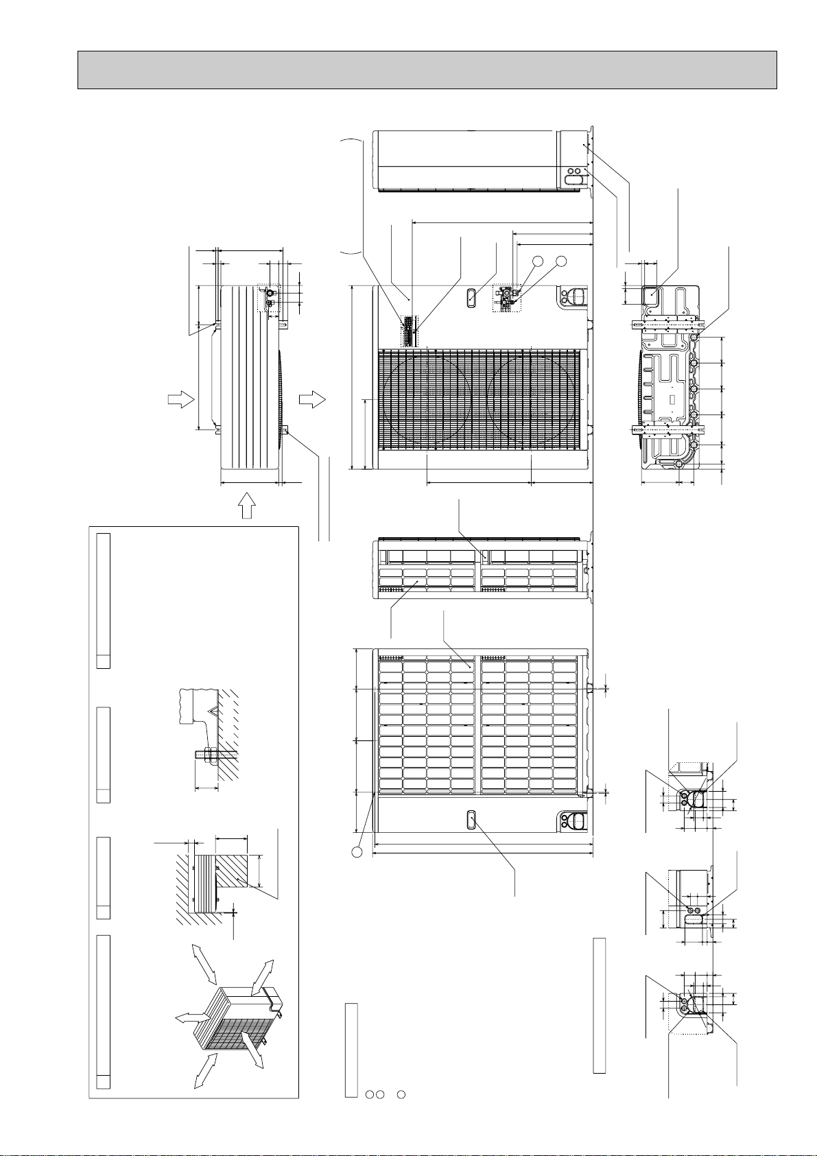
PUH-P125YGAA
PUH-P140YGAA
PU-P125YGAA
PU-P140YGAA
Unit : mm
29
225600
2-U Shaped notched holes
(Foundation Bolt M10)
Installation Feet
Rear Air Intake
Side Air
Intake
330
1033
Terminal Connections
Left...Power supply Wiring
370 (14)
53
50
4453
58
Right..Indoor/Outdoor Wiring
Service Panel
1050
Earth Point
Handle
w1 478
w1 422
1
2
Rear Piping Cover
Bottom Piping Hole
70 18
Front Piping Cover
1870
(Knock-Out)
Drain Hole
(5-[33Holes)
14814814817230 109
Air Discharge
398
20
598
352
21585
Handle
2-12x40 oval holes
(Foundation Bolt M10)
PIPING-WIRING DIRECTIONS
4
Piping and wiring connections
can be made from 4 directions:
Front, Right, Rear and Below.
FOUNDATION
FOUNDATION BOLTS
Please secure the unit firmly
with 4 foundation (M10) bolts.
(Bolts and washers must be
purchased locally).
30mm
Less than
<Foundation bolt height>
Over100
Over500
Over500
Service Space
SERVICE SPACE
23
Dimensions of space needed
for service access are
shown in the below diagram.
Over10
m
m
ver 10m
O
ver 500m
O
m
FRE
E
FREE SPACE (Around the Unit)
The diagram below shows a
basic example.
Explanation of particular details are
1
given in the installation manuals etc.
v
O
er 10m
ver 100m
O
m
Rear
Side
Air
Intake
230295295230
3
Refrigerant GAS pipe connection(FLARE) [19.05 (3/4F)
Refrigerant LIQUID pipe connection(FLARE) [9.52 (3/8F)
. . .
. . .
Explanation of Notes
2
1
Air
Height of STOP VALVE connection location.
3-[3.6 holes (for securing the top of the unit)
. . .
. . .
These holes are provided for cases where the unit must
be secured by the base AND by the top surface together.
3
w1
Intake
1246
1260
Handle
Use Self Tapping screws 5 x L15 or less.
(Obtained Locally)
55
Rear Trunking Hole
(Knock-Out)
92
92
[
< Rear Side >
40
5522
6368
4055
1002733
6368
5522
[92
33
50
33
92
Power Supply Wiring Hole
(2-[27Knock-Out)
< Right Side >
100
Power Supply Wiring Hole
(2-[27Knock-Out)
40
< Front Side >
Power Supply Wiring Hole
(2-[27Knock-Out)
Piping Knock-Out Hole Details
Front Trunking Hole
(Knock-Out)
Rear Piping Hole
(Knock-Out)
65
Right Piping Hole
(Knock-Out)
50
65
Front Piping Hole
(Knock-Out)
55
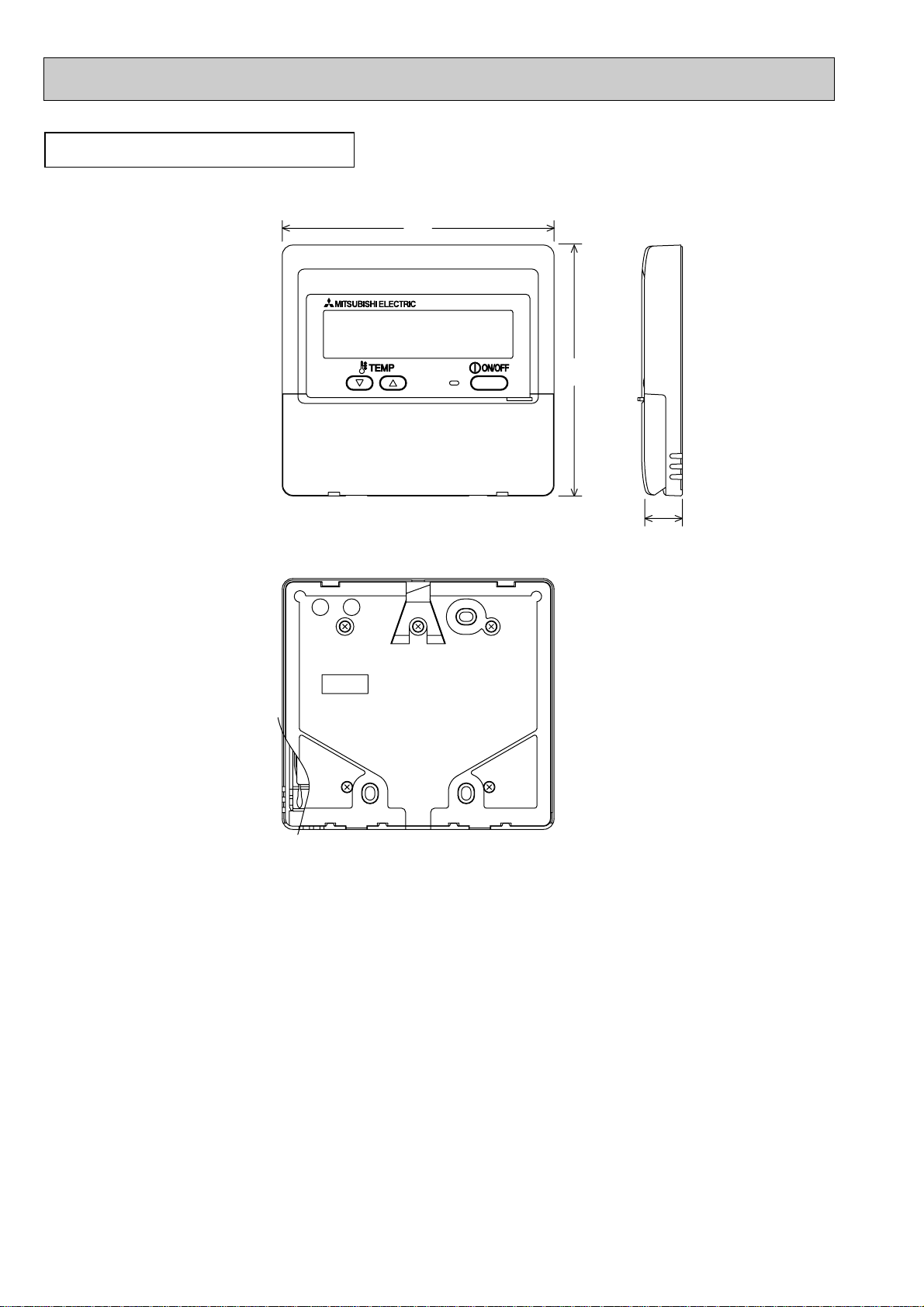
WIRED REMOTE CONTROLLER
130
120
19
Unit : mm
56

WIRELESS REMOTE CONTROLLER
159.3
55
58
19
Unit : mm
57
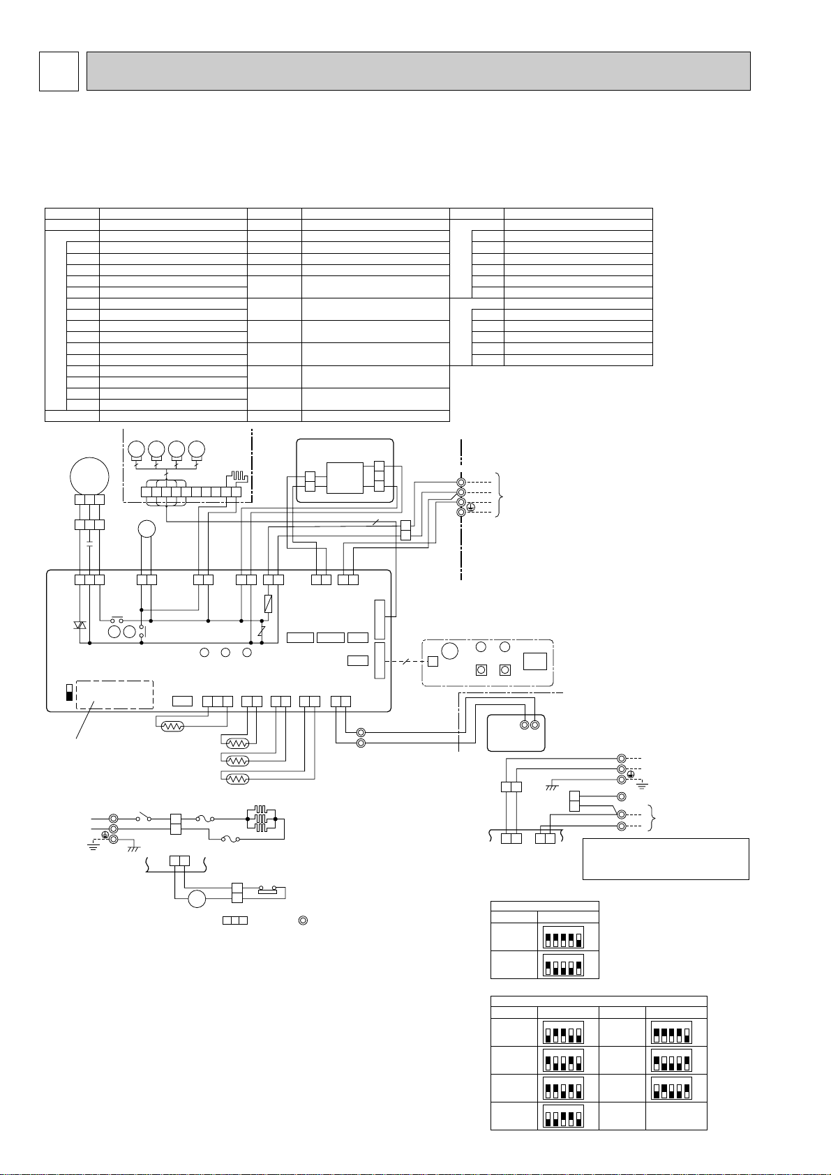
4
INDOOR POWER BOARD
[LEGEND]
P.B
INDOOR CONTROLLER BOARDI.B
FUSE(T6.3AL250V)FUSE
CN2L
VARISTORZNR
CONNECTOR(LOSSNAY)
CN32
FAN CONTROL ELEMENTBCR
CONNECTOR(REMOTE SWITCH)
CN41 CONNECTOR(HA TERMINAL-A)
CN51 CONNECTOR(CENTRALLY CONTROL)
SW1
SWITCH(MODEL SELECTION)wSee table 1
SWITCH(
CAPACITY CORD
)wSee table 2
SW2
SWE
CONNECTOR(EMERGENCY OPERATION)
X1 RELAY(DRAIN PUMP)
X4 RELAY(FAN MOTOR)
LED1 POWER SUPPLY(I.B)
LED2 POWER SUPPLY(I.B)
LED3 TRANSMISSION(INDOOR-OUTDOOR)
SYMBOL NAME SYMBOL NAME SYMBOL NAME
C CAPACITOR(FAN MOTOR)
MF FAN MOTOR
MV VANE MOTOR
DP DRAIN-UP MACHINE
DS DRAIN SENSOR
H2 DEW PREVENTION HEATER
TB4 TERMINAL BLOCK (INDOOR/
OUTDOOR CONNECTING LINE)
TB2
TERMINAL BLOCK (HEATER)wPLH-P.AAH
models only or option for PLA-RP.AA models.
TB5, TB6 TERMINAL BLOCK(REMOTE
CONTROLLER TRANSMISSION LINE)
TH1 ROOM TEMP.THERMISTOR
(0:/15k",25:/5.4k" DETECT)
TH2 PIPE TEMP.THERMISTOR/LIQUID
(0:/15k",25:/5.4k" DETECT)
TH5 COND./EVA. TEMP. THERMISTOR
(0:/15k",25:/5.4k" DETECT)
R.B
WIRED REMOTE CONTROLLER BOARD
W.B
HEATER
WIRELESS REMOTE CONTROLLER BOARD
RU RECEIVING UNIT
FS1 THERMAL FUSE(72:, 16A)
FS2 THERMAL FUSE(104:, 16A)
H1 HEATER
26H HEATER THERMAL SWITCH
88H HEATER CONTACTOR
BZ BUZZER
LED1 LED(RUN INDICATOR)
LED2 LED(HOT ADJUST)
SW1 SWITCH(HEATING ON/OFF)
SW2 SWITCH(COOLING ON/OFF)
321
321
531
MF
FAN
(WHT)
RED
WHT
BLK
BLK
X1
X4
X1X4
C
BCR
31
DP
D.U.M
CNP
(BLU)
YLW
YLW
ORN
ORN
YLW
31 31 31 31
YLW
YLW
D.HEATER
CNC(RED)
RED
WHT
WHT
BRN
POWER
CNDK
(RED)
POWER
CND
(ORN)
21
POWER
CN2D
(WHT)
INDOOR/OUTDOOR
COMMUNICATION
CN3C
(BLU)
3131
POWER
CND
(ORN)
INDOOR/OUTDOOR
COMMUNICATION
CN3C
(BLU)
CN41CN51 CN2L
CN32
9
WIRELESS
CN90
(WHT)
BZ
5
VANE
CN6V
(GRN)
CN2S
(WHT)
CNSK
(RED)
W.B
LED2
CNB
LED1
SW1 SW2
RU
21
2
21
1
REMOCON
CN22
(BLU)
TB5
TRANSMISSION WIRES
DC12V
TB6
R.B
BLU
BLU
321 21 21
D.SENSOR
CN31
(WHT)
INTAKE
CN20
(RED)
HEATER
CN24
(YLW)
LIQUID
CN21
(WHT)
DS
TH2
21
PIPE
CN29
(BLK)
TH3
TH1
LED3 LED2 LED1
ON
OFF
SWE
Refer to tables 1
and 2.
SW2 SW1
9 5
10
76321 84
5MV5MV5
5
MV5MV
GRILLE
H2
S1
S2
TB2
TB4
POWER SUPPLY
~(1PHASE)
230V 50Hz
RED
BLU
YLW
ORN
ORN
BRN
GRN/YLW
S3
TB4
TO OUTDOOR UNIT
TO OUTDOOR UNIT
L
S1
S2
S3
N
DC
13.1V
1
2
2
3
1
P.B
ZNR
FUSE
I.B
I.B
YLW
ORN
BRN
ORN
YLW
ORN
W1 (Fig.1)
Please set the voltage using the
remote controller.
For the setting method. please refer to
the indoor unit Installation Manual.
1 2 3 4 5
ON
OFF
MODELS
Table 1
SW1
Manufacture/Service
PLA-RP. AA
1 2 3 4 5
ON
OFF
MODELS
Table 2
SW2
Manufacture/Service
PLA-RP35AA
PLH-P35AAH
PLA-RP50AA
PLH-P50AAH
PLA-RP60AA
PLH-P60AAH
PLA-RP71AA
PLH-P71AAH
PLA-RP100AA
PLH-P100AAH
PLA-RP125AA
PLH-P125AAH
PLA-RP140AA
PLH-P140AAH
1 2 3 4 5
ON
OFF
1 2 3 4 5
ON
OFF
1 2 3 4 5
ON
OFF
1 2 3 4 5
ON
OFF
MODELS
Manufacture/Service
1 2 3 4 5
ON
OFF
1 2 3 4 5
ON
OFF
1 2 3 4 5
ON
OFF
PLH-P. AAH
TB2
I.B
HEATER CN24
(YLW)
[PLH-P.AAH models only]
POWER SUPPLY
~(1PHASE)
230V 50Hz
88H
FS1
26H
FS2
H1
L
RED RED RED
BLU
GRN/YLW
WHT
WHT
WHTGRY
N
2
1
2
6
5
1
88H
YLW
YLW
NOTES:
1.Symbols used in wiring diagram above are, : Connector, : Terminal (block).
2.Indoor and outdoor connecting wires are made with polarities, make wiring
matching terminal numbers (S1,S2,S3).
3.Since the outdoor side electric wiring may change be sure to check the outdoor
unit electric wiring for servicing.
4.This dlagram shows the wiring of Indoor and Outdoor connecting wires
(specification of 230V), adopting superimposed system of power and signal.
w1 ; When work to supply power separately to Indoor and Outdoor unit was applied, refer to Fig1.
w2 ; For power supply system of this unit, refer to the caution label located near this diagram.
WIRING DIAGRAM
PLA-RP35AA PLA-RP50AA PLA-RP60AA PLA-RP71AA PLA-RP100AA
PLA-RP125AA PLA-RP140AA
PLH-P35AAH PLH-P50AAH PLH-P60AAH PLH-P71AAH PLH-P100AAH
PLH-P125AAH PLH-P140AAH
58

PMH-P25BA PMH-P35BA PMH-P50BA
[LEGEND]
SYMBOL
I.B INDOOR CONTROLLER BOARD
CN2L CONNECTOR(LOSSNAY)
CN32 CONNECTOR(REMOTE SWITCH)
CN41 CONNECTOR(HA TERMINAL-A)
FUSE FUSE(6.3A , 250V)
LED1 POWER SUPPLY(I.B)
LED2 POWER SUPPLY(R.B)
LED3 TRANSMISSION(INDOOR-OUTDOOR)
SW1 JUMPER WIRE(MODEL SELECTION)
SW2 JUMPER WIRE(CAPACITY CORD)
SWE SWITCH(EMERGENCY OPERATION)
T TRANSFORMER
X1 RELAY(DRAIN PUMP)
ZNR VARISTOR
R.B
DP DRAIN-UP MACHINE
DS DRAIN SENSOR
MF FAN MOTOR
MV
TB4
TB5,TB6 TERMINAL BLOCK
TH1 ROOM TEMP, THERMISTOR
TH2 PIPE TEMP, THERMISTOR / LIQUID
TH5 COND, / EVA, TEMP, THERMISTOR
WIRED REMOTE CONTROLLER BOARD
VANE MOTOR
TERMINAL BLOCK
(INDOOR / OUTDOOR CONNECTING LINE)
(REMOTE CONTROL TRANSMISSION LINE)
(0:/15k", 25:/5.4k" DETECT)
(0:/15k", 25:/5.4k" DETECT)
(0:/15k", 25:/5.4k" DETECT)
NAME
NOTES:
1.Since the outdoor side electric wiring may change be sure
to check the outdoor unit electric wiring for servicing.
2.Indoor and outdoor connecting wires are made with polarities,
make wiring matching terminal numbers (S1, S2, S3).
3.Symbols used in wiring diagram above are,
: Connector, : Terminal (block).
Please set the voltage using the remote controller.
For the setting method, please refer to the indoor
unit Installation Manual.
<w1>
MODELS
PMH-P25/35/50BA
SW1
PMH-P25BA
SW2
PMH-P35BA
PMH-P50BA
Manufacture
J11 J12 J13 J14 J15
J21 J22 J23 J24
J21 J22 J23 J24
J21 J22 J23 J24
TB4
S1
S2
S3
Service board
12345
1234
1234
1234
ON
OFF
ON
OFF
ON
OFF
ON
OFF
TO OUTDOOR UNIT
DP
BRN
ORN
YLW
BLU
BLU
MF
I.B
LED1 CN90 CN32
6 5 4 3 251
FAN
(WHT)
5
3
1
POWER
CN03
(RED)
FUSE
ZNR
1
3
D.U.M
CNP
(YLW)
X1
TB5
2
TRANSMISSION WIRES DC12V
1
BLU
BLU
2 1
REMOTE
CONTROLLER
CN22
(BLU)
T
X1
LED2
D.SENSOR
LED3
CN31
(WHT)
INTAKE
CN20
(RED)
LIQUID
CN21
(WHT)
PIPE
CN29
(BLK)
VANE
CN6V
(WHT)
3
2
1
2
1
2
1
2
1
6
5
4
3
2
1
CN41
CN2L
BLK
BLK
BLK
BLK
BLK
BLK
BLK
BLK
BRN
RED
ORN
YLW
GRN
R.B
12
TB6
DS
TH1
TH2
TH5
1
2
3
MV
4
5
ON
OFF
J11
J12
J13
SW1SWE
J14
59
J15
J21
J22
J23
SW2
J24
See fig :w1

PEAD-RP35EA PEAD-RP50EA PEAD-RP60EA PEAD-RP71EA
PEAD-RP100EA PEAD-RP125EA PEAD-RP140EA
60

PEHD-P35EAH PEHD-P50EAH PEHD-P60EAH PEHD-P71EAH
PEHD-P100EAH PEHD-P125EAH PEHD-P140EAH
61

PEAD-P60GA PEAD-P71GA PEAD-P100GA
62

PKA-RP35GAL PKA-RP50GAL PKH-P35GALH PKH-P50GALH
INTAKE
CN20
(
RED
)
LIQUID
CN21
(
WHT
)
PIPE
CN29
(
BLK
)
1 2
1 2
1 2
1 31 31 3 1 2
TH5TH1
TH2
REMOCON
CN22
(
BLU
)
1 2
2
1
TB5
R.B
TB6
2
1
TRANSMISSION WIRES DC12V
SWE
ON
OFF
SW2 SW1
LED3 LED2 LED1
ZNR
FUSE
X4
CN41 CN2L
CN51 CN32
WIRELESS
CN90
(
WHT
)
VANE
CN6V
(
GRN
)
MV
6
W.B
BZ
CNB
RECEIVER
RU
LED1 LED2 SW2SW1
9
FAN
(
WHT
)
1 3 5
1
1
2
1
2
3
2 3
BLK
WHT
WHT
RED
RED
C
MF
X4
BCR
TO
OUTDOOR
UNIT
TB4
S1
S2
S3
YLW
ORN
ORN
BRN
YLW
ORN
BLK
WHT
P.B
I.B
POWER
CNDK
(RED)
CNDK
(RED)
DC13.1V
CN2S
(WHT)
POWER
CND
(ORN)
POWER
CN2D(WHT)
INDOOR/OUTDOOR
COMMUNICATION
CN3C(BLU)
3131
POWER
CND
(ORN)
INDOOR/OUTDOOR
COMMUNICATION
CN3C
(BLU)
TB2
TB4
POWER
SUPPLY
~(1PHASE)
230V 50Hz
RED
BLU
YLW
ORN
ORN
BRN
TO
OUTDOOR
UNIT
L
S1
S2
S3
N
I.B
YLW
ORN
w1 (Fig.1)
Refer to tables 1
and 2 for service PCB.
GRN/YLW
TB2
I.B
HEATER
CN24
(YLW)
POWER SUPPLY
~(1PHASE)
230V 50Hz
88H
FS2
26H
H1
L
REDRED 5 3RED
BLU
GRN/YLW
WHT
RED
61
REDGRY
N
2
1
2
6
5
1
FS1
88H
YLW
YLW
SW1
Service board
SW2
Service board Service board
1 2 3 4 5
ON
OFF
1 2 3 4 5
ON
OFF
MODELS
PKA-RP35GAL
PKH-P35GALH
1 2 3 4 5
ON
OFF
MODELS
PKA-RP50GAL
PKH-P50GALH
Please set the voltage using the
remote controller.
For the setting method,please refer to
the indoor unit Installation Manual.
PKH-P35,50GALH models only
P.B
INDOOR POWER BOARD
SYMBOL NAME
I.B
INDOOR CONTROLLER BOARD
FUSE FUSE (T6.3AL250V)
ZNR VARISTOR
CN2L CONNECTOR <LOSSNAY>
CN32 CONNECTOR <REMOTE SWITCH>
CN41 CONNECTOR <HA TERMINAL-A>
CN51 CONNECTOR <CENTRALLY CONTROL>
SW1 SWITCH <MODEL SELECTION>wSee Table 1.
SW2 SWITCH <CAPACITY CODE>wSee Table 2.
SWE SWITCH <EMERGENCY OPERATION>
X4 RELAY <FAN MOTOR>
BCR
POWER SUPPLY <R.B>
LED1 POWER SUPPLY <I.B>
LED2
TRANSMISSION <INDOOR-OUTDOOR>LED3
FAN CONTROL ELEMENT
C CAPACITOR <FAN MOTOR>
FAN MOTOR
VANE MOTOR
MF
MV
SYMBOL NAME
TB4
TERMINAL BLOCK <INDOOR/ OUTDOOR
TB2
TERMINAL BLOCK (HEATER) wPKH-P.GALH
models only or option for PKA-RP.GAL models.
CONNECTING LINE>
TERMINAL BLOCK <REMOTE CONTROLLER
TRANSMISSION LINE> <OPTION>
ROOM TEMP.THERMISTOR
<0:/ 15k", 25:/ 5.4k" DETECT>
PIPE TEMP.THERMISTOR/ LIQUID
<0:/ 15k", 25:/ 5.4k" DETECT>
COND./ EVA.TEMP.THERMISTOR
<0:/ 15k", 25:/ 5.4k" DETECT>
TB5,TB6
TH5
TH1
TH2
W.B
WIRELESS REMOTE CONTROLLER BOARD
RECEIVING UNIT
BUZZER
LED <RUN INDICATOR>
LED <HOT ADJUST>
SWITCH (HEATING ON/ OFF>
SWITCH (COOLING ON/ OFF>
WIRED REMOTE CONTROLLER BOARD
R.B
HEATER
RU
BZ
LED1
LED2
SW1
SW2
NAMESYMBOL
HEATER
H1
THERMAL FUSE <84:10A>
FS2
THERMAL FUSE <104:10A>
FS1
HEATER THERMAL SWITCH
26H
HEATER CONTACTOR
88H
NOTES:
1. Since the outdoor side electric wiring may change be sure to check the outdoor unit electric wiring for servicing.
2. Indoor and outdoor connecting wires are made with polarities, make wiring matching terminal numbers (S1, S2, S3).
3. Make sure that the main power supply of the booster heater is independent.
4. Symbols used in wiring diagram above are, : Connector, : Terminal (block).
w1. When work to supply power separately to Indoor and Outdoor unit was applied, refer to Fig 1.
w2. For power supply system of this unit, refer to the caution label located near this diagram.
63

PKA-RP60FAL PKA-RP71FAL PKA-RP100FAL
INTAKE
CN20
(
RED
)
LIQUID
CN21
(
WHT
)
PIPE
CN29
(
BLK
)
1 2
1 2
1 2
1 31 31 3 1 2
TH5TH1
TH2
REMOCON
CN22
(
BLU
)
1 2
2
1
TB5
R.B
TB6
2
1
TRANSMISSION WIRES DC12V
SWE
ON
OFF
SW2 SW1
LED3 LED2 LED1
ZNR
FUSE
X4
CN41 CN2L
CN51 CN32
WIRELESS
CN90
(
WHT
)
VANE
CN6V
(
GRN
)
MV
6
W.B
BZ
CNB
RECEIVER
RU
LED1 LED2 SW2SW1
9
FAN
(
WHT
)
1 3 5
1
1
2
1
2
3
2 3
BLK
WHT
WHT
RED
RED
C
MF
X4
BCR
TO
OUTDOOR
UNIT
TB4
S1
S2
S3
YLW
ORN
ORN
BRN
YLW
ORN
BLK
WHT
P.B
I.B
Please set the voltage
using the remote controller.
For the setting method,
please refer to the indoor
unit Installation Manual
SW1
Table 1
Service board
SW2
Table 2
Service board Service board Service board
POWER
CNDK
(RED)
CNDK
(RED)
DC13.1V
CN2S
(WHT)
POWER
CND
(ORN)
POWER
CN2D(WHT)
INDOOR/OUTDOOR
COMMUNICATION
CN3C(BLU)
3131
POWER
CND
(ORN)
INDOOR/OUTDOOR
COMMUNICATION
CN3C
(BLU)
TB2
TB4
POWER
SUPPLY
(1PHASE)
230V 50Hz
RED
BLU
YLW
ORN
ORN
BRN
TO
OUTDOOR
UNIT
L
S1
S2
S3
N
I.B
YLW
ORN
w
1 (Fig.1)
Refer to tables 1
and 2 for service PCB.
1 2 3 4 5
ON
OFF
1 2 3 4 5
ON
OFF
MODELS
PKA-RP60FAL
PKH-P60FALH
1 2 3 4 5
ON
OFF
MODELS
PKA-RP71FAL
PKH-P71FALH
1 2 3 4 5
ON
OFF
MODELS
PKA-RP100FAL
PKH-P100FALH
TB2
I.B
HEATER
CN24
(YLW)
PKH-P60 P100FALH models only
POWER SUPPLY
(1PHASE)
230V 50Hz
88H
FS2
26H
H1
L
REDRED 5 3RED
BLU
GRN/YLW
WHT
RED
61
REDGRY
N
2
1
2
6
5
1
FS1
88H
YLW
YLW
GRN/YLW
P.B
INDOOR POWER BOARD
SYMBOL NAME
I.B
INDOOR CONTROLLER BOARD
FUSE FUSE(T6.3AL250V)
ZNR VARISTOR
CN2L CONNECTOR(LOSSNAY)
CN32 CONNECTOR(REMOTE SWITCH)
CN41 CONNECTOR(HA TERMINAL-A)
CN51 CONNECTOR(CENTRALLY CONTROL)
SW1 SWITCH (MODEL SELECTION)
w
See Table 1.
SW2 SWITCH (CAPACITY CODE)
w
See Table 2.
SWE SWITCH(EMERGENCY OPERATION)
X4 RELAY(FAN MOTOR)
BCR
POWER SUPPLY(R.B)
LED1 POWER SUPPLY(I.B)
LED2
TRANSMISSION(INDOOR-OUTDOOR)LED3
FAN CONTROL ELEMENT
C CAPACITOR(FAN MOTOR)
FAN MOTOR
VANE MOTOR
MF
MV
SYMBOL NAME
TB4
TERMINAL BLOCK(INDOOR/OUTDOOR
TB2
TERMINAL BLOCK (HEATER) wPKH-P.FALH
models only or option for PKA-RP.FAL models.
CONNECTING LINE)
TERMINAL BLOCK(REMOTE CONTROLLER
TRANSMISSION LINE )(OPTION)
ROOM TEMP.THERMISTOR
(0
;
/15k', 25;/5.4k' DETECT)
PIPE TEMP.THERMISTOR/LIQUID
(0
;
/15k', 25;/5.4k' DETECT)
COND./EVA.TEMP.THERMISTOR
(0
;
/15k', 25;/5.4k' DETECT)
TB5
TH5
TH1
TH2
W.B
WIRELESS REMOTE CONTROLLER BOARD
RECEIVING UNIT
BUZZER
LED(RUN INDICATOR )
LED(HOT ADJUST)
SWITCH(HEATING ON/OFF)
SWITCH(COOLING ON/OFF)
WIREDREMOTE CONTROLLER BOARD(OPTION)
TERMINAL BLOCK(REMOTE CONTROLLER
THERMAL FUSE(117
;
10A:60,71FALH/
117
;
16A:100FALH)
TRANSMISSION LINE)
R.B
HEATER
RU
BZ
LED1
LED2
SW1
SW2
NAMESYMBOL
HEATER
H1
HEATER THERMAL SWITCH
26H
HEATER CONTACTOR
88H
TB6
FS1,2
NOTES:
1. Since the outdoor side electric wiring may change be sure to check the outdoor unit electric wiring for servicing.
2. Indoor and outdoor connecting wires are made with polarities, make wiring matching terminal numbers (S1, S2, S3).
3. Make sure that the main power supply of the booster heater is independent.
4. Symbols used in wiring diagram above are, : Connector, : Terminal (block).
w
1. When work to supply power separately to Indoor and Outdoor unit was applied, refer to Fig 1.
w
2. For power supply system of this unit, refer to the caution label located near this diagram.
PKA-P60FALH PKA-P71FALH PKA-P100FALH
64

PCA-RP50GA PCA-RP60GA PCA-RP71GA PCA-RP100GA PCA-RP125GA
X4 X1
FAN
(
WHT
)
1 3 1 3 1 3 1 35
1 2 3
BLK
WHT
RED
C
MF
DP
X4
X1
BCR
POWER
CNDK
(RED)
D.U.M
CNP
(BLU)
(OPTION)
ZNR
POWER
CND
(ORN)
1
2
1
2
3
P.B
I.B
CNDK
(RED)
DC13.1V
CN2S
(WHT)
WHT
RED
YLW
ORN
BLK
BLK
BLK
BLK
BLK
BLU
BLU
BRN
ORN
WHT
FUSE
1 2
POWER
CN2D(WHT)
1 3
INDOOR/OUTDOOR
COMMUNICATION
CN3C(BLU)
SWE
ON
OFF
SW2 SW1
Refer to tables 1
and 2 for service PCB.
LED3 LED2 LED1
TO OUTDOOR UNIT
TB4
S1
S2
S3
YLW
ORN
ORN
BRN
50~71 TYPE
CN41 CN2L
CN51 CN32
VANE
CN6V
(
GRN
)
MV
6 6
9
MV
6 6
WIRELESS
CN90
(
WHT
)
INTAKE
CN20
(
RED
)
LIQUID
CN21
(
WHT
)
D.SENSOR
CN31
(
WHT
)
CN31
DRAIN SENSOR
DS
PIPE
CN29
(
BLK
)
1 21 2 3
1 2 3
1 2
1 2
TH5TH1
TH2
REMOCON
CN22
(
BLU
)
1 2
2
1
TB5
R.B
TB6
12
TRANSMISSION WIRES DC12V
1 2
1 2
W.B
BZ
CNB
RECEIVER
RU
LED1 LED2 SW2 SW1
100~140 TYPE
MV
5 5
3131
POWER
CND
(ORN)
INDOOR/OUTDOOR
COMMUNICATION
CN3C
(BLU)
TB2
TB4
POWER SUPPLY
~(1PHASE)
230V 50Hz
RED
BLU
YLW
GRN/YLW
ORN
ORN
BRN
TO OUTDOOR UNIT
L
S1
S2
S3
N
I.B
YLW
ORN
W
1 (Fig.1)
(
WHT
)
I.B
HEATER
CN24
(YLW)
26H
RED
61
REDGRY
2
6
5
1
88H
YLW
YLW
TB2
POWER SUPPLY
~(1PHASE)
230V 50Hz
88H
FS2
H1
L
REDRED 5 3RED
BLU
GRN/YLW
WHT
N
2
1
FS1
PCH-P50~P140GAH
models only
Please set the voltage using the remote
controller.
For the setting method, please refer to
the indoor unit Installation Manual.
SW1
Table 1
Service board
1 2 3 4 5
ON
OFF
MODELS
PCA-RP.GA
PCH-P.GAH
SW2
Table 2
Service board
1 2 3 4 5
ON
OFF
MODELS
PCA-RP50GA
PCH-P50GAH
1 2 3 4 5
ON
OFF
PCA-RP60GA
PCH-P60GAH
1 2 3 4 5
ON
OFF
PCA-RP71GA
PCH-P71GAH
Service board
1 2 3 4 5
ON
OFF
MODELS
PCA-RP100GA
PCH-P100GAH
1 2 3 4 5
ON
OFF
PCA-RP125GA
PCH-P125GAH
1 2 3 4 5
ON
OFF
PCA-RP140GA
PCH-P140GAH
P.B
INDOOR POWER BOARD
SYMBOL NAME
I.B
INDOOR CONTROLLER BOARD
FUSE FUSE (T6.3AL250V)
ZNR VARISTOR
CN2L CONNECTOR(LOSSNAY)
CN32 CONNECTOR(REMOTE SWITCH)
CN41 CONNECTOR(HA TERMINAL-A)
CN51 CONNECTOR(CENTRALLY CONTROL)
SW1 SWITCH (MODEL SELECTION) WSee Table 1.
SW2 SWITCH (CAPACITY CODE) WSee Table 2.
SWE SWITCH(EMERGENCY OPERATION)
X4 RELAY(FAN MOTOR)
X1 RELAY(DRAIN PUMP)
BCR
POWER SUPPLY(R.B)
LED1 POWER SUPPLY(I.B)
LED2
TRANSMISSION(INDOOR-OUTDOOR)LED3
FAN CONTROL ELEMENT
C CAPACITOR(FAN MOTOR)
FAN MOTOR
VANE MOTOR
MF
MV
DRAIN-UP MACHINE (OPTION)
DP
DRAIN SENSOR (OPTION)
DS
SYMBOL NAME
TB4
TERMINAL BLOCK(INDOOR/OUTDOOR CONNECTING LINE)
TB2
TERMINAL BLOCK (HEATER) WPCH-P.GAH
models only or option for PCA RP.GA models.
TERMINAL BLOCK(REMOTE CONTROLLER
TRANSMISSION LINE )
ROOM TEMP.THERMISTOR
(0;/15k', 25;/5.4k' DETECT)
PIPE TEMP.THERMISTOR/LIQUID
(0;/15k', 25;/5.4k' DETECT)
COND./EVA.TEMP.THERMISTOR
(0;/15k', 25;/5.4k' DETECT)
TB5,TB6
TH5
TH1
TH2
W.B
WIRELESS REMOTE CONTROLLER BOARD(OPTION)
RECEIVING UNIT
BUZZER
LED(RUN INDICATOR)
LED(HOT ADJUST)
SWITCH(HEATING ON/OFF)
SWITCH(COOLING ON/OFF)
WIRED REMOTE CONTROLLER BOARD
R.B
HEATER
RU
BZ
LED1
LED2
SW1
SW2
NAMESYMBOL
HEATER
H1
HEATER THERMAL SWITCH
26H
HEATER CONTACTOR
88H
THERMAL FUSE(
98;10A:50GAH/117;16A:100GAH
110;16A:60,71,125,140GAH)
FS1,2
NOTES:
1. Since the outdoor side electric wiring may change be sure to
check the outdoor unit electric wiring for servicing.
2. Indoor and outdoor connecting wires are made with polarities, make
wiring matching terminal numbers (S1, S2, S3).
3. Make sure that the main power supply of the booster heater is
independent.
4. Symbols used in wiring diagram above are,
: Connector, : Terminal (block).
W
1. When work to supply power separately to
Indoor and Outdoor unit was applied, refer to Fig 1.
W
2. For power supply system of this unit,
refer to the caution label located near this diagram.
[Servicing]
Fasten terminal of the terminal board "TB4"equips lock system.
To remove the fastened terminal, pull it while pressing the protruding
portion (locking lever) of the terminal. The fastened terminal protruding
portion should face upward.
When installing drain-up
machine (Optional part).
W
When installing optional
drain-up machine disconnect
the CN31 jumper connector
and replace it with the
drain sensor (DS).
PCA-RP140GA
PCH-P50GAH PCH-P60GAH PCH-P71GAH PCH-P100GAH PCH-P125GAH
PCH-P140GAH
65
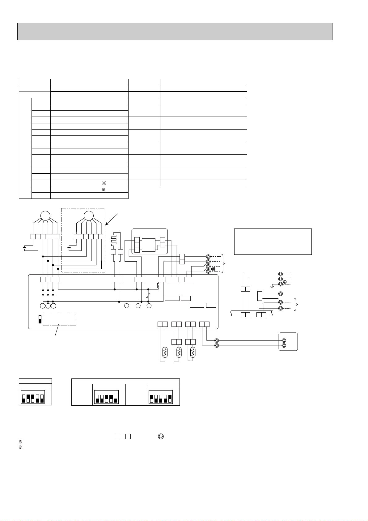
PCA-RP71HA PCA-RP125HA
SYMBOL
[ LEGEND ]
NAME SYMBOL NAME
INDOOR POWER BOARD
INDOOR CONTROLLER BOARD
FUSE (T6.3AL250V)
MF1, MF2
C1, C2
H2
FAN MOTOR
CAPACITOR(FAN MOTOR)
DEW PREVENTION HEATER
VARISTOR
CONNECTOR (LOSSNAY)
CONNECTOR (REMOTE SWITCH)
CONNECTOR (HA TERMINAL-A)
CONNECTOR (CENTRALLY CONTROLL)
POWER SUPPLY (I. B)
POWER SUPPLY (R. B)
TRANSMISSION(INDOOR-OUTDOOR)
RELAY (DEW PREVENTION HEATER)
RELAY(FAN MOTOR)
RELAY(FAN MOTOR)
RELAY(FAN MOTOR)
SWITCH (MODEL SELECTION)
See Table 1.
SWITCH (CAPACITY CODE) See Table 2.
SWITCH (EMERGENCY OPERATION)
P. B
I. B
FUSE
ZNR
CN2L
CN32
CN41
CN51
LED1
LED2
LED3
X1
X4
X5
X6
SW1
TB2
TB4
TB5,TB6
TH1
TH2
TH5
R. B
TERMINAL BLOCK(INDOOR UNIT
POWER (OPTION))
TERMINAL BLOCK(INDOOR/OUTDOOR
CONNECTING LINE)
TERMINAL BLOCK(REMOTE CONTROLLER
TRANSMISSION LINE)
ROOM TEMP.THERMISTOR
(0˚C/15kΩ, 25˚C/5.4kΩ DETECT)
PIPE TEMP.THERMISTOR/LIQUID
(0˚C/15kΩ, 25˚C/5.4kΩ DETECT)
COND./ EVA.TEMP.THERMISTOR
(0˚C/15kΩ, 25˚C/5.4kΩ DETECT)
WIRED REMOTE CONTROLLER BOARD
SW2
SWE
Service board
SW1
Table 1
1 2 3 4 5
ON
OFF
Service board
SW2
Table 2
1 2 3 4 5
MODELS
PCA-RP71HA
ON
OFF
Service board
1 2 3 4 5
MODELS
PCA-RP125HA
ON
OFF
1357
MF1
BLU
BLK
WHT
YLW
BLU
BLK
WHT
YLW
ORN
ORN
C1
RED
RED
13 13 13 12
1
2
1
2
3
13
11
654321
MF2
BLU
YLW
YLW
ORN
BLK
RED
WHT
WHT
YLW
BLK
WHT
YLW
BLU
BLK
WHT
YLW
ORN
BRN
C2
GRY
RED
654321
D.HEATER
CNC
(RED)
For PCA-RP125HA
X6 X5 X4
X6 X5 X4
ZNR
FUSE
SWE
FAN
(WHT)
SW2 SW1
LED3 LED2 LED1
H2
OFF
ON
12 12 12
12 13
12
WHT
WHT
REMOCON
CN22
(BLU)
TH1 TH2 TH5
BLU
BLU
BLK
BLK
1
2
2
1
TB5
INTAKE
CN20
(RED)
LIQUID
CN21
(WHT)
PIPE
CN29
(BLK)
R.B
TB6
TRANSMISSION WIRES DC12V
CN41 CN2L
CN32CN51
ROWER
CNDK
(RED)
ROWER
CND
(ORN)
DC13.1V
CNDK
(RED)
CN2S
(WHT)
P.B
I.B
BRN
YLW
ORN
ORN
S1
S2
S3
TB4
TO
OUTDOOR
UNIT
ROWER
CN2D(WHT)
INDOOR/OUTDOOR
COMMUNICATION
CN3C(BLU)
Refer to tables 1
and 2 for service PCB.
Please set the voltage using the
remote controller.
For the setting method, please refer to
the indoor unit Installation Manual.
3131
POWER
CND
(ORN)
INDOOR/OUTDOOR
COMMUNICATION
CN3C
(BLU)
TB4
POWER
SUPPLY
~(1PHASE)
230V 50Hz
RED
TB2
BLU
TO
OUTDOOR
UNIT
L
S1
S2
S3
N
I.B
YLW
ORN
ORN
ORN
YLW
GRN/YLW
BRN
w1 (Fig.1)
NOTES:
1.Since the outdoor side electric wiring may change be sure to check the outdoor unit electric wiring for servicing.
2.Indoor and outdoor connecting wires are made with polarities, make wiring matching terminal numbers (S1,S2,S3).
3.Symbols used in wiring diagram above are, : Connector, : Terminal (block).
1 ; When work to supply power separately to Indoor and Outdoor unit was applied, refer to Fig1.
2 ; For power supply system of this unit, refer to the caution label located near this diagram.
66

PSA-RP71GA PSA-RP100GA PSA-RP125GA PSA-RP140GA
1357
MF
ORN
C
RED
BLK
BLU
YLW
13 13 13 12
1
2
2
1
3
13
ML
YLW
YLW
BLK
ORN
YLW
YLW
ORNS1S2
S3
WHT
WHT
WHT
BRN
ORN
RED
I.B
FAN
(WHT)
LOUVER
CNL
(YLW)
X4X5X6
X6
X5 X4
X2
ZNR
FUSE
X2
LED3 LED2 LED1
SWE
ON
OFF
POWER
CNDK
(RED)
POWER
CND
(ORN)
POWER
CN2D
(WHT)
WIRELESS
CN90
(WHT)
2
1
REMOCON
CN22
(BLU)
CN32
CN2L
2
1
TB6
2
2
1
1
2
1
LIQUID
CN21
(WHT)
INTAKE
CN20
(RED)
PIPE
CN29
(BLK)
CN24 CN41
CN51
R.B
TRANSMISSION
WIRES DC12V
BLU
BLU
TH1
TH2
TH5
SW1SW2
TB4
REDRED
WHT
RED
BLU
GRN/YLW
88H
FS1FS2
H
53
1
2
L
N
TB2
POWER SUPPLY
~(1 PHASE)
230V 50Hz
2
1
6
5
RED
RED
YLW
26H
88H
YLW
YLW
16
HEATER
CN24
(YLW)
I.B
PSH -P.GAH
models only
INDOOR UNIT
Please set the voltage using the
remote controller.
For the setting method, please refer to
the indoor unit Installation Manual.
INDOOR/OUTDOOR
COMMUNICATION
CN3C
(BLU)
Refer to tables 1
and 2 for service PCB.
P.B
CNSK
(RED)
CN2S
(WHT)
DC13.1V
TO
OUTDOOR
UNIT
3131
POWER
CND
(ORN)
INDOOR/OUTDOOR
COMMUNICATION
CN3C
(BLU)
TB2
TB4
POWER SUPPLY
~(1PHASE)
230V 50Hz
RED
BLU
GRY/YLW
RED
BLU
TO
OUTDOOR
UNIT
L
S1
S2
S3
N
I.B
YLW
ORN
ORN
BRN
1 (Fig.1)
Service board
SW2
Table 2
1 2 3 4 5
MODELS
PSA-RP71GA
PSH-P71GAH
PSA-RP100GA
PSH-P100GAH
PSA-RP125GA
PSH-P125GAH
PSA-RP140GA
PSH-P140GAH
ON
OFF
1 2 3 4 5
ON
OFF
1 2 3 4 5
ON
OFF
1 2 3 4 5
ON
OFF
Service board
SW2
Table 1
1 2 3 4 5
MODELS
PSA-RP.GA
PSH-P.GAH
ON
OFF
P.B
INDOOR POWER BOARD
SYMBOL NAME SYMBOL NAME SYMBOL NAME
I.B
I.B
INDOOR CONTROLLER BOARD
FUSE FUSE (T6.3AL250V)
ZNR VARISTOR
CN2L CONNECTOR (LOSSNAY)
CN32 CONNECTOR (REMOTE SWITCH)
CN41 CONNECTOR (HA TERMINAL-A)
CN51 CONNECTOR (CENTRALLY CONTROL)
SW1
SWITCH (MODEL SELECTION) See Table 1.
SW2
SWITCH (CAPACITY CODE) See Table 2.
SWE SWITCH (EMERGENCY OPERATION)
X4 RELAY (FAN MOTOR)
X5 RELAY (FAN MOTOR)
X6 RELAY (FAN MOTOR)
X2
RELAY (LOUVER)
POWER SUPPLY (R.B)
LED1 POWER SUPPLY (I.B)
LED2
TRANSMISSION (INDOOR-OUTDOOR)LED3
WIRED REMOTE CONTROLLER BOARD
TERMINAL BLOCK (REMOTE CONTROLLER
TRANSMISSION LINE)
R.B
TB6
HEATER
HEATER
THERMAL FUSE (110˚C16A)
H
FS1,2
HEATER THERMAL SWITCH
26H
HEATER CONTACTOR
88H
C CAPACITOR (FAN MOTOR)
FAN MOTOR
MF
LOUVER MOTOR
ML
TB2
TERMINAL BLOCK
(INDOOR/OUTDOOR CONNECTING LINE)
TB4
TERMINAL BLOCK (HEATER) PSH-P.GAH
models only or option for PSA-RP.GA models.
ROOM TEMP.THERMISTOR
(0˚C/15kΩ, 25˚C/5.4kΩ DETECT)
PIPE TEMP.THERMISTOR/LIQUID
(0˚C/15kΩ, 25˚C/5.4kΩ DETECT)
COND./EVA.TEMP.THERMISTOR
(0˚C/15kΩ, 25˚C/5.4kΩ DETECT)
TH1
TH2
TH5
[NOTES]
1.Symbols used in wiring diagram above are, : Connector, : Terminal (block).
2.Indoor and outdoor connecting wires are made with polarities, make wiring
matching terminal numbers (S1,S2,S3).
3.Since the outdoor side electric wiring may change be sure to check the outdoor
unit electric wiring for servicing.
4.This diagram shows the wiring of Indoor and Outdoor connecting wires
(specification of 230V), adopting superimposed system of power and signal.
1 ; When work to supply power separately to Indoor and Outdoor unit
was applied, refer to Fig1.
2 ; For power supply system of this unit, refer to the caution label
located near this diagram.
PSH-P71GAH PSH-P100GAH PSH-P125GAH PSH-P140GAH
67

PUH-P25VGAA PUH-P35VGAA PUH-P50VGAA PUH-P60VGAA PUH-P71VGAA
PUH-P100VGAA
PU-P35VGAA PU-P50VGAA PU-P60VGAA PU-P71VGAA PU-P100VGAA
SYMBOL NAME SYMBOL NAME
MC COMPRESSOR (INNER THERMOSTAT)
MF FAN MOTOR (INNER THERMOSTAT)
TH3 THERMISTOR LIQUID TEMP
TH4 DISCHARGE TEMP
TH6 COND. / EVA. TEMP
C3 MF CAPACITOR
C4 MF CAPACITOR
C5 MC CAPACITOR
CH CRANKCASE HEATER
52C MC CONTACTOR
21S4 4-WAY VALVE SOLENOID COIL
63H HIGH PRESSURE PROTECT SWITCH
49C INNER THERMOSTAT FOR MC
TB1 TERMINAL BLOCK
LEV LINEAR EXPANSION VALVE
TB2 TERMINAL BLOCK
MC
49C
SCR
MF
MF
*2
a
b
63H
WHT
BLK
WHT
BLK
BRN
BRN
WHT
WHT
BLU
BLU
C5
B
W
R
E
D
C4
L
H
U
T
*1
C3
52C
CH
2
6
/
/
T
T
1
21S4
3
52C
1
5
/
/
L
L
1
3
BLU
RED
B
R
L
E
U
D
LN
TB1
TB2
S1
O
Y
R
L
N
W
S2
(PNK)
(BLU)
21S4
(GRN)
B
R
N
S3
MF4
(WHT)
MF3
(WHT)
52C
CH
4/S
O.B OUTDOOR CONTROLLER BOARD
FUSE1 (O.B) FUSE (6.3A)
FUSE2 (O.B) FUSE (6.3A)
FUSE3 (O.B) FUSE (6.3A)
FUSE4 (O.B) FUSE (6.3A)
X51 (O.B) MC/CH RELAY
X52 (O.B) 21S4 RELAY
F.C (O.B) FAN CONTROLLER
SW1 (O.B) GROUP NUMBER ADDRESS
SW4 (O.B) TEST RUN
SW5 (O.B) FUNCTION SELECTION
J1)~J6 (O.B) MODEL SELECTION
T (O.B) TRANSFORMER
CT (O.B) CURRENT TRANS
LED1 (O.B)
LED2 (O.B)
CN31 (O.B) EMERGENCY OPERATION CONNECTER
CT
F.C
CNM
X51
OPERATION CHECK DISPLAY LED
OPERATION CHECK DISPLAY LED
CNVMNT
(WHT)
CNMNT
(WHT)
LED1 (GRN)
LED2 (RED)
ON
SW5
SW1 SW4
CNLEV
(WHT)
(WHT)
OFF
J6
TH3/TH6
(RED)
X52
J1J2J3J4J5
CN31
T
FUSE2
R
FUSE1
FUSE4
FUSE3
S1
S2
S3
*1 PU(H)-P100VGAA MODEL ONLY
*2 PUH-P25~ P100VGAA MODEL ONLY
TH4
O.B
BRN
RED
BLU
ORN
YLW
WHT
BLK
BLK
GRY
LEV
TH4
TH6
TH3
INDOOR
S3
UNIT
S2
POWER SUPPLY
~/ N
230V 50Hz
<Notes when servicing>
Some fastening terminals have a lock mechanism: When removing the fastening terminal, push the projection (locking lever) on the terminal with
your finger and pull it out.
S1
TB4
68

PUH-P35YGAA PUH-P50YGAA PUH-P60YGAA PUH-P71YGAA PUH-P100YGAA
PUH-P125YGAA PUH-P140YGAA
PU-P35YGAA PU-P50YGAA PU-P60YGAA PU-P71YGAA PU-P100YGAA
PU-P125YGAA PU-P140YGAA
SYMBOL NAME SYMBOL NAME
MC COMPRESSOR
MF FAN MOTOR (INNER THERMOSTAT)
TH3 THERMISTOR LIQUID TEMP
TH4 DISCHARGE TEMP
TH6 COND. / EVA. TEMP
C3 MF CAPACITOR
C4 MF CAPACITOR
CH CRANKCASE HEATER
52C MC CONTACTOR
21S4 4-WAY VALVE SOLENOID COIL
SV BYPASS VALVE SOLENOID COIL
63H HIGH PRESSURE PROTECT SWITCH
51C THERMAL RELAY
TB1 TERMINAL BLOCK
LEV LINEAR EXPANSION VALVE
TB2 TERMINAL BLOCK
63L LOW PRESSURE PROTECT SWITCH
MC
UVW
R
W
B
E
H
L
T
K
*2
6
4
/
/
T
T
3
2
51C
52C
5
3
/
/
L
L
3
2
BLK
WHT
RED
W
B
B
H
L
L
T
K
U
3N~
400V 50Hz
C4
C3
CH
*4
*1
*3
D
2
/
T
1
1
/
L
1
R
E
D
L1 L2 L3 N
TB1
POWER SUPPLY
<Notes when servicing>
Some fastening terminals have a lock mechanism: When removing the fastening terminal, push the projection (locking lever) on the terminal with
your finger and pull it out.
52C
21S4
SV
PE
MF
MF
a
b
51C
63L
63H
WHT
BLK
WHT
BLK
BRN
BRN
WHT
WHT
BLU
BLU
BLK
BLK
ORN
ORN
WHT
WHT
TB2
S1
Y
L
W
(*1BLK)
(*1BLK)
O
R
N
S2
MF4
(WHT)
MF3
(WHT)
52C
(PNK)
(BLU)
21S4
(GRN)
(BLK)
51CM
(ORN)
(RED)
B
R
N
S3
CH
SV
FUSE2
63L
4/S
O.B OUTDOOR CONTROLLER BOARD
FUSE1 (O.B) FUSE (6.3A)
FUSE2 (O.B) FUSE (6.3A)
FUSE3 (O.B) FUSE (6.3A)
FUSE4 (O.B) FUSE (6.3A)
X51 (O.B) MC/CH RELAY
X52 (O.B) 21S4 RELAY
X53 (O.B) SV RELAY
F.C (O.B) FAN CONTROLLER
SW1 (O.B) GROUP NUMBER ADDRESS
SW4 (O.B) TEST RUN
SW5 (O.B) FUNCTION SELECTION
J1~J6 (O.B) MODEL SELECTION
T (O.B) TRANSFORMER
CT (O.B) CURRENT TRANS
LED1 (O.B) OPERATION CHECK DISPLAY LED
LED2 (O.B) OPERATION CHECK DISPLAY LED
CN31 (O.B) EMERGENCY OPERATION CONNECTER
O.B
X51
X52
X53
F.C
RST
CT
TB4
CNM
ON
OFF
FUSE1
S3
S2
S1
CNVMNT
SW5
CN31
FUSE4
FUSE3
INDOOR
UNIT
CNMNT
(WHT)
LED1 (GRN)
LED2 (RED)
SW1 SW4
J1J2J3J4J5
S1
S2
S3
(WHT)
J6
CNLEV
(WHT)
TH4
(WHT)
TH3/TH6
(RED)
T
*1 PUH-P125/140YGAA MODEL ONLY
*2 PU(H)-P100/125/140YGAA MODEL ONLY
*3 PU(H)-P125/140YGAA MODEL ONLY
*4 PUH-P35~ P140YGAA MODEL ONLY
BRN
RED
BLU
ORN
YLW
WHT
BLK
BLK
GRY
LEV
TH4
TH6
TH3
69

5
Thermistor TH2
Pipe temperature (Liquid)
Distributor
with strainer(#50)
Thermistor TH5
(Cond./Eva. temperature)
Thermistor TH1
(Room temperature)
Refrigerant flow in cooling
Refrigerant flow in heating
Strainer(#50)
Strainer(#50)
Heat exchanger
Refrigerant GAS pipe connection
(Flare)
Refrigerant LIQUID pipe connection
(Flare)
REFRIGERANT SYSTEM DIAGRAM
5.1 INDOOR UNIT
PLA-RP•AA PLH-P•AAH PMH-P•BA
PEAD-RP•EA PEHD-P•EAH PEAD-RP•GA
PKA-RP•GAL PKH-P•GALH PKA-RP•FAL PKH-P•FALH
PCA-RP•GA PCH-P•GAH PCA-RP•HA
PSA-RP•GA PSH-P•GAH
70

Service
port
Accumulator
Compressor
Refrigerant GAS pipe
19.05A({3/4")
Refrigerant LIQUID pipe
9.52A({3/8")
Stop valve
(with service port)
4-way valve
Service
port
High pressure
protect switch
Thermistor
(TH3)
Capillary tube
(O.D.4.0✕I.D.3.0-L350)✕2pcs
Refrigerant flow in cooling
Refrigerant flow in heating
Liner expansion valve
Thermistor
(TH4)
Muffler
Thermistor
(TH6)
Distributor
with
strainer
Ball valve
(#50)
Strainer
(#100)
Strainer
(#100)
Strainer
Service
port
Accumulator
Ball valve
Compressor
Refrigerant GAS pipe
P25···12.7A({1/2")
P35~P71···15.88A({5/8")
Refrigerant LIQUID pipe
P25···6.35A({1/4")
P35~P71···9.52A({3/8")
Stop valve
(with service port)
4-way valve
Service
port
High pressure
protect switch
Outdoor heat exchanger
Thermistor
(TH3)
Thermistor
(TH6)
Distributor
with
strainer
Muffler
Thermistor(TH4)
Linear expansion valve
Refrigerant flow in cooling
Refrigerant flow in heating
(#50)
Strainer
(#100)
Strainer
(#100)
Strainer
Service
port
Accumulator
Compressor
Refrigerant GAS pipe
19.05A({3/4")
Refrigerant LIQUID pipe
9.52A({3/8")
4-way
valve
Service
port
High pressure protect switch
Thermistor
(TH3)
Capillary tube
(O.D.4.0✕I.D.3.0-L200)✕2pcs
Drier
Liner expansion valve
Muffler
Thermistor
(TH4)
Thermistor
(TH6)
Distributor
with
strainer
Refrigerant flow in cooling
Refrigerant flow in heating
w1 : O.D.4.0✕I.D.2.0-L400(PUH-P125)
O.D.4.0✕I.D.3.0-L450(PUH-P140)
Ball valve
(#50)
Strainer
Strainer
(#100)
Strainer
(#100)
Strainer
(#50)
Low pressure protect
switch
Stop valve
(with service port)
Capillary
tube w1
5.2 OUTDOOR UNIT
PUH-P25VGAA PUH-P35VGAA PUH-P50VGAA PUH-P60VGAA PUH-P71VGAA
PUH-P35YGAA PUH-P50YGAA PUH-P60YGAA PUH-P71YGAA
<4-way valve solenoid coil>
Heating : ON
Cooling : OFF
PUH-P100VGAA
PUH-P100YGAA
PUH-P125YGAA
PUH-P140YGAA
71

Service
port
Accumulator
Compressor
Refrigerant GAS pipe
19.05A({3/4")
Refrigerant LIQUID pipe
9.52A({3/8")
Stop valve
(with service port)
Service
port
High pressure
protect switch
Thermistor
(TH3)
Capillary tube
(O.D.4.0✕I.D.3.0-R350)✕2pcs
Refrigerant flow in cooling
Liner expansion valve
Thermistor
(TH4)
Thermistor
(TH6)
Distributor
with
strainer
Ball valve
(#50)
Strainer
(#100)
Strainer
(#100)
Strainer
PU-P35VGAA PU-P50VGAA PU-P60VGAA PU-P71VGAA
Service
port
Accumulator
Compressor
Refrigerant GAS pipe
15.88A({5/8")
Refrigerant LIQUID pipe
9.52A({3/8")
Stop valve
(with service port)
Service
port
High pressure
protect switch
Outdoor heat exchanger
Thermistor
(TH3)
Thermistor
(TH6)
Distributor
with
strainer
Thermistor(TH4)
Linear expansion valve
Refrigerant flow in cooling
Ball valve
(#50)
Strainer
(#100)
Strainer
(#100)
Strainer
Service
port
Accumulator
Compressor
Refrigerant GAS pipe
19.05A({3/4")
Refrigerant LIQUID pipe
9.52A({3/8")
Service
port
High pressure
protect switch
Thermistor
(TH3)
Capillary tube
(O.D.4.0✕I.D.3.0-L200)✕2pcs
Drier
Thermistor
(TH4)
Thermistor
(TH6)
Distributor
with
strainer
Refrigerant flow in cooling
Stop valve
(with service port)
Liner expansion valve
Ball valve
(#50)
Strainer
Strainer
(#100)
Strainer
(#100)
(#50)
Strainer
Low pressure protect
switch
PU-P35YGAA PU-P50YGAA PU-P60YGAA PU-P71YGAA
PU-P100VGAA
PU-P100YGAA
PU-P125YGAA
PU-P140YGAA
72

PERFORMANCE CURVES6
1.4
1.2
1.0
0.8
10
22
20
18
16
22
20
18
16
20 30 46400-5
1.2
1.0
0.8
0.6
0.4
INDOOR
W.B.(°C)
CAPACITY (RATIO)TOTAL INPUT (RATIO)
INDOOR
W.B.(°C)
OUTDOOR D.B.(°C)
Cooling performance curve(50Hz)
73

1.4
1.2
1.0
15
20
25
25
20
15
0.8
0.6
0.4
1.4
1.2
1.0
0.8
0.6
0.4
-12 -10 -5 0 5 10 15
INDOOR
D.B.(°C)
INDOOR
D.B.(°C)
OUTDOOR W.B.(°C)
CAPACITY (RATIO)TOTAL INPUT (RATIO)
Correcting the capacity line influenced by frosting
Not correcting the capactiy line influenced by frosting
Heating performance curve(50Hz)
74
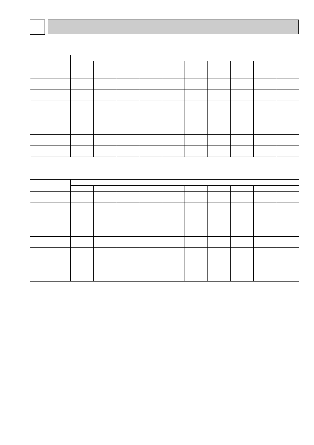
CORRECTION FACTORS7
Outdoor unit
Refrigerant piping length (one way)
5m
1.00
1.00
1.00
1.00
1.00
1.00
1.00
1.00
0.993
0.993
0.993
0.989
0.981
0.989
0.981
0.975
0.984
0.984
0.984
0.980
0.968
0.980
0.968
0.955
0.978
0.978
0.978
0.970
0.952
0.970
0.952
0.935
0.969
0.969
0.969
0.960
0.940
0.960
0.940
0.918
0.961
0.961
0.961
0.950
0.925
0.950
0.925
0.900
—
0.956
0.956
0.940
0.913
0.940
0.913
0.884
—
0.948
0.948
0.930
0.900
0.930
0.900
0.869
—
—
—
0.920
0.886
0.920
0.886
0.855
—
—
—
0.910
0.874
0.910
0.874
0.840
10m 15m 20m 25m 30m 35m 40m 45m 50m
Outdoor unit
Refrigerant piping length (one way)
5m
1.00
1.00
1.00
1.00
1.00
1.00
1.00
1.00
0.998
0.998
0.998
0.998
0.998
0.998
0.998
0.998
0.995
0.995
0.995
0.995
0.995
0.995
0.995
0.995
0.993
0.993
0.993
0.993
0.993
0.993
0.993
0.993
0.990
0.990
0.990
0.990
0.990
0.990
0.990
0.990
0.988
0.988
0.988
0.988
0.988
0.988
0.988
0.988
—
0.985
0.985
0.985
0.985
0.985
0.985
0.985
—
0.983
0.983
0.983
0.983
0.983
0.983
0.983
—
—
—
0.980
0.980
0.980
0.980
0.980
—
—
—
0.978
0.978
0.978
0.978
0.978
10m 15m 20m 25m 30m 35m 40m 45m 50m
Cooling capacity correction factors
Heating capacity correction factors
PUH-P25VGAA
PU(H)-P35VGAA
PU(H)-P35YGAA
PU(H)-P50VGAA
PU(H)-P50YGAA
PU(H)-P60VGAA
PU(H)-P60YGAA
PU(H)-P71VGAA
PU(H)-P71YGAA
PU(H)-P100VGAA
PU(H)-P100YGAA
PUH-P125YGAA
PU-P125YGAA
PUH-P140YGAA
PU-P140YGAA
PUH-P25VGAA
PUH-P35VGAA
PUH-P35YGAA
PUH-P50VGAA
PUH-P50YGAA
PUH-P60VGAA
PUH-P60YGAA
PUH-P71VGAA
PUH-P71YGAA
PUH-P100VGAA
PUH-P100YGAA
PUH-P125YGAA
PUH-P140YGAA
75

8
PLA-RP71AA
PLH-P71AAH
PLA-RP100AA
PLH-P100AAH
PLA-RP125AA
PLH-P125AAH
PLA-RP140AA
PLH-P140AAH
28
4.9
7.4
30
6.6
8.9
30
6.6
8.9
Air flow
Air speed
Coverage range
m
3
/min.
m/sec.
m
20
4.0
5.7
14
2.8
4.0
18
3.6
5.2
18
3.6
5.2
PLA-RP35AA
PLH-P35AAH
PLA-RP50AA
PLH-P50AAH
PLA-RP60AA
PLH-P60AAH
Air flow
Air speed
Coverage range
m
3
/min
m/sec
m
PCA-RP50GA
PCH-P50GAH
PCA-RP60GA
PCH-P60GAH
PCA-RP71GA
PCH-P71GAH
PCA-RP100GA
PCH-P100GAH
PCA-RP125GA
PCH-P125GAH
PCA-RP140GA
PCH-P140GAH
25
4.1
12.6
34
4.4
15.2
34
4.4
15.2
18
3.8
10.4
18
3.8
10.4
13
3.7
8.8
Air flow
Air speed
Coverage range
m3/min
m/sec
m
19
2.9
7.9
38
4.2
13.2
PCA-RP71HA PCA-RP125HA
12
5.3
10(32.8)
PKA-RP35GAL
PKH-P35GALH
12
5.3
10(32.8)
PKA-RP50GAL
PKH-P50GALH
Air flow
Air speed
Coverage range
m
3
/min
m/sec
m(ft)
20
4.9
12.4(40.7)
PKA-RP71FAL
PKH-P71FALH
20
4.9
12.4(40.7)
PKA-RP60FAL
PKH-P60FALH
28
5.4
15.3(50.2)
PKA-RP100FAL
PKH-P100FALH
Air flow
Air speed
Coverage range
m
3
/min
m/sec
m(ft)
Air flow
Air speed
Coverage range
m
3
/min
m/sec
m
PSA-RP71GA
PSH-P71GAH
PSA-RP100GA
PSH-P100GAH
PSA-RP125GA
PSH-P125GAH
PSA-RP140GA
PSH-P140GAH
18
2.6
8.3
31
4.5
14.3
33
4.8
15.2
35
4.9
16.1
10.0
4.3
7.0
8.4
3.7
5.9
11.0
4.7
7.7
PMH-P25BA
PMH-P35A
PMH-P50BA
Air flow
Air speed
Coverage range
m
3
/min
m/sec
m
AIR FLOW DATA
8-1. OUTLET AIR SPEED AND COVERAGE RANGE
The air coverage range is the value up to the position where the air speed is 0.25m/sec. when air is blown out horizontally from
the unit at the Hi notch position.
The coverage range should be used only as a general guideline since it varies according to the size of the room and the furniture inside the room.
76
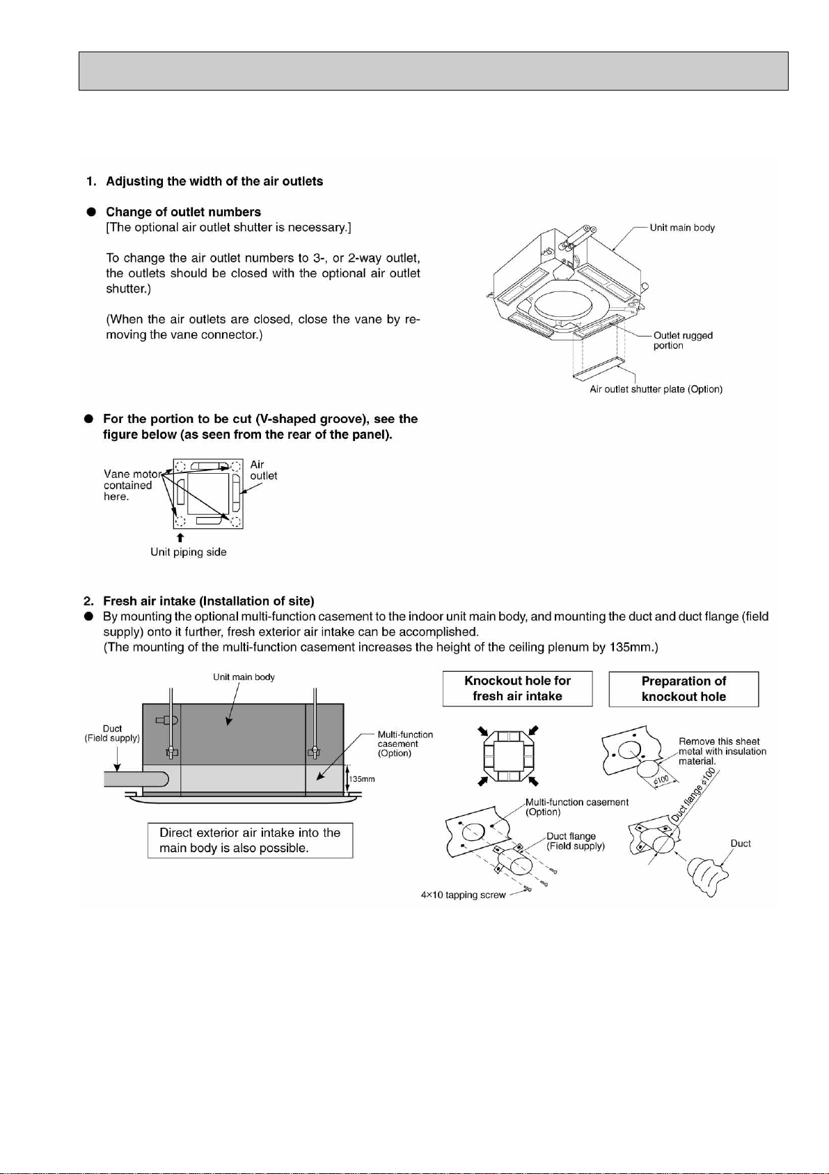
8-2. PLA-RP•AA, PLH-P•AAH
8-2-1. FRESH AIR INTAKE AMOUNT
77

8-2-2. BRANCH DUCT (Installation at site)
78

Branch duct air flow rate/static pressure characteristics
PLA-RP35AA
PLH-P35AAH
4-way air flow (horizontal vane) Rectangular duct 4-way air flow (horizontal vane) Round duct
3-way air flow (horizontal vane) Rectangular duct 3-way air flow (horizontal vane) Round duct
2-way air flow (horizontal vane) Rectangular duct 2-way air flow (horizontal vane) Round duct
79

PLA-RP50AA PLA-RP60AA
PLH-P50AAH PLH-P60AAH
4-way air flow (horizontal vane) Rectangular duct 4-way air flow (horizontal vane) Round duct
3-way air flow (horizontal vane) Rectangular duct 3-way air flow (horizontal vane) Round duct
2-way air flow (horizontal vane) Rectangular duct 2-way air flow (horizontal vane) Round duct
80
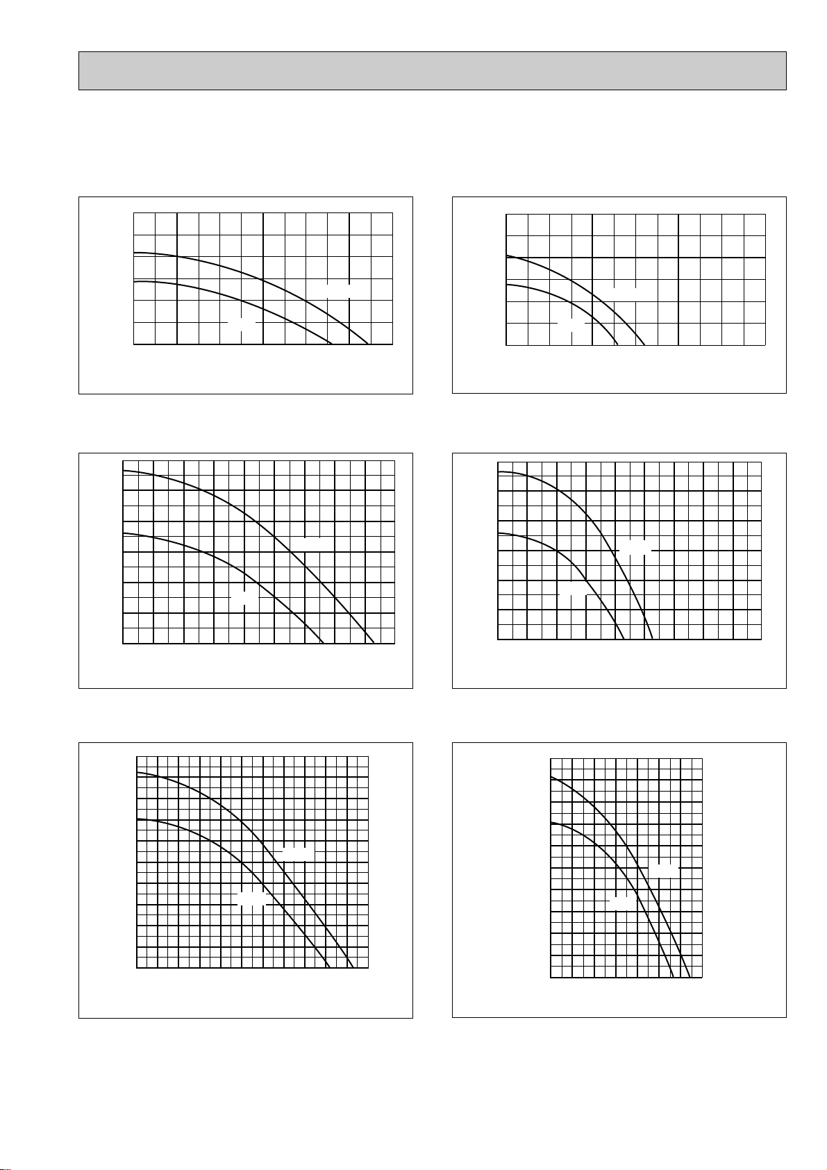
PLA-RP71AA
PLH-P71AAH
4-way air flow (horizontal vane) Rectangular duct 4-way air flow (horizontal vane) Round duct
Static pressure [Pa]
30
20
10
High
Low
0
123456
Air flow rate [m
3
/min]
Static pressure [Pa]
30
20
10
High
Low
0
123456
Air flow rate [m
3-way air flow (horizontal vane) Rectangular duct 3-way air flow (horizontal vane) Round duct
Static pressure [Pa]
60
50
40
30
20
10
High
Low
0
123456789
Air flow rate [m
3
/min]
60
50
40
30
20
10
Static pressure [Pa]
High
Low
0
123456789
Air flow rate [m
3
/min]
3
/min]
2-way air flow (horizontal vane) Rectangular duct 2-way air flow (horizontal vane) Round duct
100
Static pressure [Pa]
90
80
70
60
50
40
30
20
10
0
1234567891011
Low
High
Air flow rate [m
3
/min]
100
90
80
70
60
50
40
30
20
Static pressure [Pa]
10
0
1234567
Air flow rate [m
Low
High
3
/min]
81

PLA-RP100AA
PLH-P100AAH
4-way air flow (horizontal vane) Rectangular duct 4-way air flow (horizontal vane) Round duct
Static pressure [Pa]
50
40
30
20
10
0
1234 5678910
Low
High
Air flow rate [m
3
/min]
Static pressure [Pa]
50
40
30
20
10
0
Low
1234 5678910
High
Air flow rate [m
3-way air flow (horizontal vane) Rectangular duct 3-way air flow (horizontal vane) Round duct
100
Static pressure [Pa]
90
80
70
60
50
40
30
20
10
0
1234567 891011121314
Low
High
Air flow rate [m
3
/min]
100
90
80
70
60
50
40
Static pressure [Pa]
30
20
10
0
Low
1234567 891011121314
High
Air flow rate [m
3
3
/min]
/min]
2-way air flow (horizontal vane) Rectangular duct 2-way air flow (horizontal vane) Round duct
120
110
100
Static pressure [Pa]
90
80
70
60
50
40
30
20
10
0
2 3 4 5 6 7 8 9 10 11 12 13 14 15 16
1
High
Low
Air flow rate [m
3
/min]
120
110
100
90
80
70
60
50
40
30
Static pressure
20
10
0
1
Low
2 3 4 5 6 7 8 9 10 11 12 13 14 15 16
High
Air flow rate [m
82
3
/min]

PLA-RP125AA PLA-RP140AA
PLH-P125AAH PLH-P140AAH
4-way air flow (horizontal vane) Rectangular duct 4-way air flow (horizontal vane) Round duct
Static pressure [Pa]
50
40
30
20
10
0
Low
12345678910
High
Air flow rate [m
50
40
30
20
10
Static pressure [Pa]
High
Low
0
12345678910
Air flow rate [m
3
/min]
3-way air flow (horizontal vane) Rectangular duct 3-way air flow (horizontal vane) Round duct
100
Static pressure [Pa]
90
80
70
60
50
40
30
20
10
0
1234567891011121314
Low
High
Air flow rate [m
3
/min]
100
Static pressure [Pa]
90
80
70
60
50
40
30
20
10
0
1234567891011121314
Low
High
Air flow rate [m
3
/min]
3
/min]
2-way air flow (horizontal vane) Rectangular duct 2-way air flow (horizontal vane) Round duct
120
110
100
Static pressure [Pa]
90
80
70
60
50
40
30
20
10
0
2 3 4 5 6 7 8 9 10 11 12 13 14 15 16
1
Air flow rate [m
Low
High
3
/min]
120
110
100
Static pressure[Pa]
90
80
70
60
50
40
30
20
10
0
2 3 4 5 6 7 8 9 10 11 12 13 14 15 16
1
Low
High
Air flow rate [m
83
3
/min]

50.0
-50.0
-100.0
0.0 0.5 1.0
Air flow (m
3
/min)
2 intakes
1 intake
Characteristic diagram of air capacity taken from outside
Static pressure (Pa)
1.5 2.0 2.5
0.0
PMH-P25BA
PMH-P35BA
PMH-P50BA
8.4m3/min
10.0m3/min
11.0m3/min
1.6m3/min
2.0m3/min
2.2m3/min
Air flow
(Hi)
Air capacity taken outside
(Knock out)
4-{2.8
Flesh air intake hole
(Knock out)
Flesh air intake hole
90-
{
122
{
100
108
250 288.5
Q
0
B
A
C
1
2
3
Curve in the
left praphs.
Duct characteristics
at site
Q
A
EC
Q
Qa
AD
8-3.PMH-P•BA
Air capacity taken from outside
PMH-P·BA series are possible to be taken air from outside.
When taking air from the outside, the duct fan can be used to.
The air capacity should be 20% or less of the air flow SPEC(Hi).
How to read curves
Q…Planned amount of fresh air intake <m
A…Static pressure loss of fresh air intake duct system with air flow amount Q <Pa>
B…Forced static pressure at air conditioner inlet with air flow amount Q <Pa>
C…Static pressure of booster fan with air flow amount Q <Pa>
D…Static pressure loss increase amount of fresh air intake duct system for air flow amount Q <Pa>
E…Static pressure of indoor unit with air flow amount Q <Pa>
Qa…Estimated amount of fresh air intake without D <m
3
/min>
3
/min>
84

8-4. PEAD-RP·EA, GA, PEHD-P·EAH
Fan Performance <30Pa>
External static pressure (Pa)
(1Pa 0.1mmAq)
Air Flow (CMM)
8610121416
10 12 14 16 18 20
20
40
60
80
100
0.8
0.9
1.0
1.1
Corrected Air Flow
Capacity
input
Cooling
Air flow (CMM)
Correction factor
Fan Performance <70Pa>
External static pressure (Pa)
(1Pa 0.1mmAq)
Air Flow (CMM)
10 126 8 14 16 18
81012141618
20
40
60
80
100
120
140
0.8
0.9
1.0
1.1
1.2
1.3
Heating
Air flow (CMM)
Correction factor
Fan Performance <30Pa>
External static pressure (Pa)
(1Pa 0.1mmAq)
Air Flow (CMM)
6 8 10 12 14 16 18 20
810121416182022
20
40
60
80
100
120
140
0.8
0.9
1.0
1.1
Corrected Air Flow
Capacity
input
Cooling
Air flow (CMM)
Correction factor
Fan Performance <70Pa>
External static pressure (Pa)
(1Pa 0.1mmAq)
Air Flow (CMM)
8 10121416182022
810121416182022
20
40
60
80
100
120
140
160
0.8
0.9
1.0
1.1
1.2
1.3
Heating
Air flow (CMM)
Correction factor
8-4-1. FAN PERFORMANCE AND CORRECTED AIR FLOW
PEAD-RP35EA PEHD-P35EAH
PEAD-RP50EA PEHD-P50EAH
85

PEAD-RP60EA PEHD-P60EAH
Fan Performance <30Pa>
External static pressure (Pa)
(1Pa 0.1mmAq)
Air Flow (CMM)
8 1012141618202224
12 14 16 18 20 22 24 26
20
40
60
80
100
120
0.8
0.9
1.0
1.1
Corrected Air Flow
Capacity
input
Cooling
Air flow (CMM)
Correction factor
Fan Performance <70Pa>
External static pressure (Pa)
(1Pa 0.1mmAq)
Air Flow (CMM)
10 12 14 16 18 20 22 24 26
12 14 16 18 20 22 24 26
20
40
60
80
100
120
140
0.8
0.9
1.0
1.1
1.2
1.3
Heating
Air flow (CMM)
Correction factor
Lo
Hi
140
120
100
200
180
160
80
60
40
20
12 16 20 24 28 32
Air flow
(CMM)
Fan performance <130Pa>
Recommended range
External static pressure (Pa)
(1Pa 0.1mmAq)
140
120
100
180
160
80
60
40
20
12 16 20 24 28 32
Air flow
(CMM)
Fan performance <70Pa>
Recommended range
External static pressure (Pa)
(1Pa 0.1mmAq)
=
Lo
Hi
Corrected Air Flow
Capacity
Input
1.1
1.0
0.9
0.8
12 16 20 24 28 32
Air flow (CMM)
Correction factor
Cooling
=
1.1
1.0
1.3
1.2
0.9
0.8
12 16 20 24 28 32
Air flow (CMM)
Correction factor
Heating
PEAD-RP71EA PEHD-P71EAH
86

PEAD-RP100EA PEHD-P100EAH
Lo
Hi
140
120
100
200
180
160
80
60
40
20
26 28 30 32 34 36 38 40
Air flow
(CMM)
Fan performance <130Pa>
Recommended range
External static pressure (Pa)
(1Pa 0.1mmAq)
140
120
100
200
220
180
160
80
60
40
20
24 26 28 30 32 34 36 38
Air flow
(CMM)
Fan performance <70Pa>
Recommended range
External static pressure (Pa)
(1Pa 0.1mmAq)
Lo
Hi
Corrected Air Flow
Capacity
Input
1.1
1.0
0.9
0.8
24 26 28 30 32 34 36 38 40
Air flow (CMM)
Correction factor
Cooling
1.1
1.0
1.2
0.9
0.8
24 26 28 30 32 34 36 38 40
Air flow (CMM)
Correction factor
Heating
=
=
Lo
Hi
140
120
100
200
220
180
160
80
60
40
20
32 34 36 38 40 42 44 46 48
Air flow
(CMM)
Fan performance <130Pa>
Recommended range
External static pressure (Pa)
(1Pa 0.1mmAq)
140
120
100
200
220
180
160
80
60
40
20
32 34 36 38 40 42 44 46
Air flow
(CMM)
Fan performance <70Pa>
Recommended range
External static pressure (Pa)
(1Pa 0.1mmAq)
Lo
Hi
Corrected Air Flow
Capacity
Input
1.1
1.0
0.9
0.8
32 34 36 38 40 42 44 46 48
Air flow (CMM)
Correction factor
Cooling
1.1
1.0
1.2
0.9
0.8
32 34 36 38 40 42 44 46 48
Air flow (CMM)
Correction factor
Heating
=
=
PEAD-RP125EA PEHD-P125EAH
87

PEAD-RP140EA PEHD-P140EAH
1.2
1.1
1.0
0.9
0.8
36 38 40 42 44 46
48
50 52
Air flow (CMM)
Correction factor
Heating
Corrected Air Flow
Capacity
Input
1.1
1.0
0.9
0.8
36 38 40 42 44 46
48 50
52
Air flow (CMM)
Correction factor
Cooling
Lo
Hi
200
180
160
140
120
100
80
60
40
20
36
38 40 42 44 46 48
50
Air flow
(CMM)
Fan performance <70Pa>
Recommended range
External static pressure (Pa)
(1Pa 0.1mmAq)
=
Lo
200
220
180
160
140
120
100
80
60
40
20
36
38 40 42 44 46 48 50
52
Air flow
(CMM)
Fan performance <130Pa>
Recommended range
External static pressure (Pa)
(1Pa 0.1mmAq)
=
Hi
88

PEAD-RP60GA
PEAD-RP71GA
89
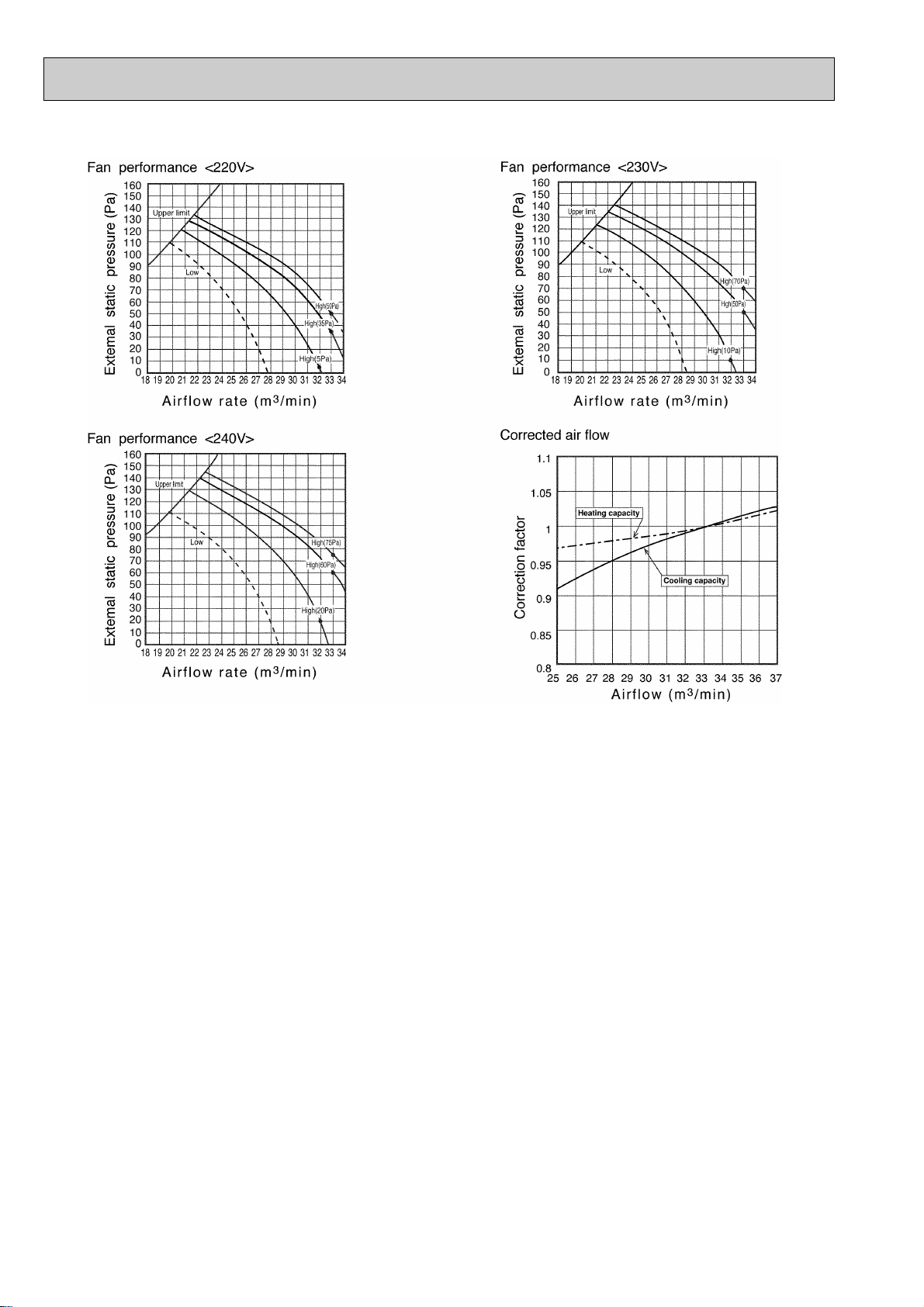
PEAD-RP100GA
90

PLA-RP35AA
PLH-P35AAH
PLA-RP50AA
PLA-RP60AA
PLH-P50AAH
PLH-P60AAH
NOTCH SPL(dB) LINE
High
Medium1
Medium2
Low
High
Medium1
Medium2
Low
31
29
28
27
NOTCH SPL(dB) LINE
33
31
29
28
90
80
70
60
50
40
30
20
10
63 125 250 500 1000 2000 4000 8000
APPROXIMATE
THRESHOLD OF
HEARING FOR
CONTINUOUS
NOISE
NC-60
NC-50
NC-40
NC-30
NC-20
NC-70
OCTAVE BAND SOUND PRESSURE LEVEL, dB (0 dB = 0.0002 µbar)
OCTAVE BAND SOUND PRESSURE LEVEL, dB (0 dB = 0.0002 µbar)
BAND CENTER FREQUENCIES, Hz
PLA-RP71AA
PLH-P71AAH
PLA-RP100AA
PLH-P100AAH
NOTCH SPL(dB) LINE
34
32
30
28
NOTCH SPL(dB) LINE
41
39
36
33
90
80
70
60
50
40
30
20
10
63 125 250 500 1000 2000 4000 8000
APPROXIMATE
THRESHOLD OF
HEARING FOR
CONTINUOUS
NOISE
NC-60
NC-50
NC-40
NC-30
NC-20
NC-70
BAND CENTER FREQUENCIES, Hz
90
80
70
60
50
40
30
20
10
63 125 250 500 1000 2000 4000 8000
APPROXIMATE
THRESHOLD OF
HEARING FOR
CONTINUOUS
NOISE
NC-60
NC-50
NC-40
NC-30
NC-20
NC-70
BAND CENTER FREQUENCIES, Hz
High
Medium1
Medium2
Low
High
Medium1
Medium2
Low
OCTAVE BAND SOUND PRESSURE LEVEL, dB (0 dB = 0.0002 µbar)
OCTAVE BAND SOUND PRESSURE LEVEL, dB (0 dB = 0.0002 µbar)
9
NOISE CRITERION CURVES
90
80
70
60
50
40
30
APPROXIMATE
20
THRESHOLD OF
HEARING FOR
CONTINUOUS
NOISE
10
63 125 250 500 1000 2000 4000 8000
BAND CENTER FREQUENCIES, Hz
NC-70
NC-60
NC-50
NC-40
NC-30
NC-20
91
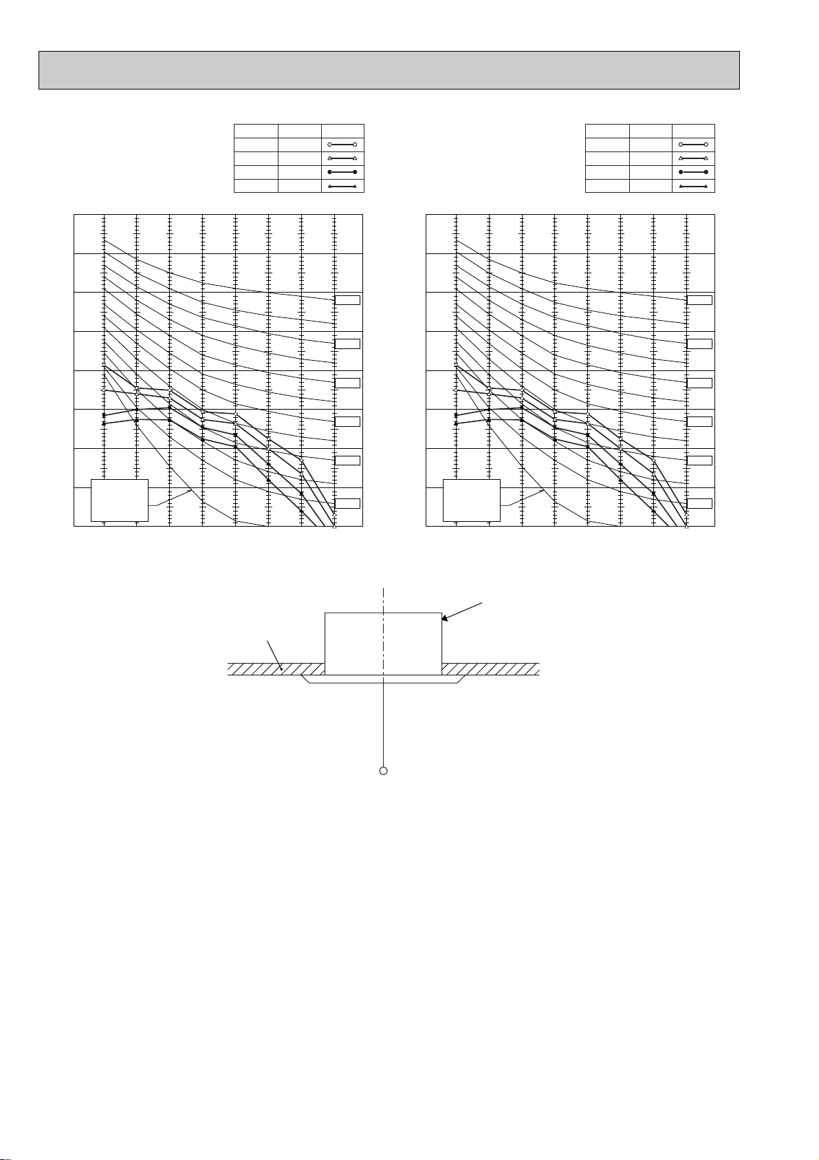
PLA-RP125AA
PLH-P125AAH
NOTCH SPL(dB) LINE
High
Medium1
Medium2
Low
45
43
40
37
PLA-RP140AA
PLH-P140AAH
NOTCH SPL(dB) LINE
High
Medium1
Medium2
Low
45
43
40
37
OCTAVE BAND SOUND PRESSURE LEVEL, dB (0 dB = 0.0002 µbar)
90
80
70
60
50
40
30
APPROXIMATE
20
THRESHOLD OF
HEARING FOR
CONTINUOUS
NOISE
10
63 125 250 500 1000 2000 4000 8000
BAND CENTER FREQUENCIES, Hz
NC-70
NC-60
NC-50
NC-40
NC-30
NC-20
OCTAVE BAND SOUND PRESSURE LEVEL, dB (0 dB = 0.0002 µbar)
90
80
70
60
50
40
30
APPROXIMATE
20
THRESHOLD OF
HEARING FOR
CONTINUOUS
NOISE
10
63 125 250 500 1000 2000 4000 8000
BAND CENTER FREQUENCIES, Hz
UNIT
NC-70
NC-60
NC-50
NC-40
NC-30
NC-20
CEILING
1.5m
MICROPHONE
92

PMH-P25BA
NOTCH
High
Medium1
Medium2
Low
SPL(dB)
35
33
31
29
LINE
PMH-P35BA
NOTCH
High
Medium1
Medium2
Low
SPL(dB)
40
38
36
34
LINE
90
80
70
60
50
40
30
20
APPROXIMATE THRESHOLD OF
OCTAVE BAND SOUND PRESSURE LEVEL, dB re 0.002µ BAR
HEARING FOR CONTINUOUS
NOISE
10
63 125 250 500 1000 2000 4000 8000
PMH-P50BA
90
BAND CENTER FREQUENCIES, Hz
NOTCH
SPL(dB)
High
Medium1
Medium2
Low
90
80
NC-70
NC-60
NC-50
NC-40
NC-30
NC-20
OCTAVE BAND SOUND PRESSURE LEVEL, dB re 0.002µ BAR
70
60
50
40
30
APPROXIMATE
20
THRESHOLD OF
HEARING FOR
CONTINUOUS
NOISE
10
63 125 250 500 1000 2000 4000 8000
BAND CENTER FREQUENCIES, Hz
NC-70
NC-60
NC-50
NC-40
NC-30
NC-20
LINE
42
40
38
UNIT
36
CEILING
OCTAVE BAND SOUND PRESSURE LEVEL, dB re 0.002µ BAR
80
70
60
50
40
30
APPROXIMATE
20
THRESHOLD OF
HEARING FOR
CONTINUOUS
NOISE
10
63 125 250 500 1000 2000 4000 8000
BAND CENTER FREQUENCIES, Hz
NC-70
NC-60
NC-50
NC-40
NC-30
NC-20
1.5m
MICROPHONE
93

PEHD-P35EAH
PEAD-RP35EA
70
60
50
40
30
20
10
Approximate minimum
audible limit on
continuous noise
OCTAVE BAND PRESSURE LEVEL (dB) 0dB = 20µPa
0
63 125 250 500 1000 2000 4000 8000
OCTAVE BAND CENTER FREQUENCIES (Hz)
(External static
pressure 30Pa)
High
Low
NC60
NC50
NC40
NC30
NC20
PEHD-P35EAH
PEAD-RP35EA
70
60
50
40
30
20
10
Approximate minimum
audible limit on
continuous noise
OCTAVE BAND PRESSURE LEVEL (dB) 0dB = 20µPa
0
63 125 250 500 1000 2000 4000 8000
OCTAVE BAND CENTER FREQUENCIES (Hz)
(External static
pressure 70Pa)
High
Low
NC60
NC50
NC40
NC30
NC20
PEHD-P50EAH
PEAD-RP50EA
70
60
50
40
30
20
10
Approximate minimum
audible limit on
continuous noise
OCTAVE BAND PRESSURE LEVEL (dB) 0dB = 20µPa
0
63 125 250 500 1000 2000 4000 8000
OCTAVE BAND CENTER FREQUENCIES (Hz)
PEHD-P60EAH
PEAD-RP60EA
70
60
50
40
30
20
10
Approximate minimum
audible limit on
continuous noise
OCTAVE BAND PRESSURE LEVEL (dB) 0dB = 20µPa
0
63 125 250 500 1000 2000 4000 8000
OCTAVE BAND CENTER FREQUENCIES (Hz)
(External static
pressure 30Pa)
(External static
pressure 30Pa)
High
Low
High
Low
NC60
NC50
NC40
NC30
NC20
NC60
NC50
NC40
NC30
NC20
PEHD-P50EAH
PEAD-RP50EA
70
60
50
40
30
20
10
Approximate minimum
audible limit on
continuous noise
OCTAVE BAND PRESSURE LEVEL (dB) 0dB = 20µPa
0
63 125 250 500 1000 2000 4000 8000
OCTAVE BAND CENTER FREQUENCIES (Hz)
PEHD-P60EAH
PEAD-RP60EA
70
60
50
40
30
20
10
Approximate minimum
audible limit on
continuous noise
OCTAVE BAND PRESSURE LEVEL (dB) 0dB = 20µPa
0
63 125 250 500 1000 2000 4000 8000
OCTAVE BAND CENTER FREQUENCIES (Hz)
(External static
pressure 70Pa)
(External static
pressure 70Pa)
High
Low
High
Low
NC60
NC50
NC40
NC30
NC20
NC60
NC50
NC40
NC30
NC20
94

95

PKA-RP35GAL
PKA-RP50GAL
PKH-P35GALH
PKH-P50GALH
90
80
NOTCH
High
Medium1
Medium2
Low
SPL(dB)
43
41
38
36
LINE
OCTAVE BAND SOUND PRESSURE LEVEL, dB (0dB=0.0002 µbar)
70
60
50
40
30
APPROXIMATE
20
TERESHOLD OF
HEARING FOR
CONTINUOUS
NOISE
10
63 125 250 500 1000 2000 4000 8000
BAND CENTER FREQUENCIES, Hz
UNIT
NC-70
NC-60
NC-50
NC-40
NC-30
NC-20
WALL
1m
1m
MICROPHONE
96

PKA-RP60FAL
PKA-RP71FAL
PKH-P60FALH
PKH-P71FALH
90
NOTCH
High
Low
SPL(dB)39LINE
45
PKA-RP100FAL
PKH-P100FALH
90
NOTCH
High
Low
SPL(dB)
46
41
LINE
OCTAVE BAND SOUND PRESSURE LEVEL, dB(0dB=0.0002 µ bar)
80
70
60
50
40
30
APPROXIMATE
20
TERESHOLD OF
HEARING FOR
CONTINUOUS
NOISE
10
63 125 250 500 1000 2000 4000 8000
BAND CENTER FREQUENCIES, Hz
NC-70
NC-60
NC-50
NC-40
NC-30
NC-20
UNIT
OCTAVE BAND SOUND PRESSURE LEVEL, dB(0dB=0.0002 µ bar)
80
70
60
50
40
30
APPROXIMATE
20
TERESHOLD OF
HEARING FOR
CONTINUOUS
NOISE
10
63 125 250 500 1000 2000 4000 8000
BAND CENTER FREQUENCIES, Hz
WALL
NC-70
NC-60
NC-50
NC-40
NC-30
NC-20
1m
1m
MICROPHONE
97
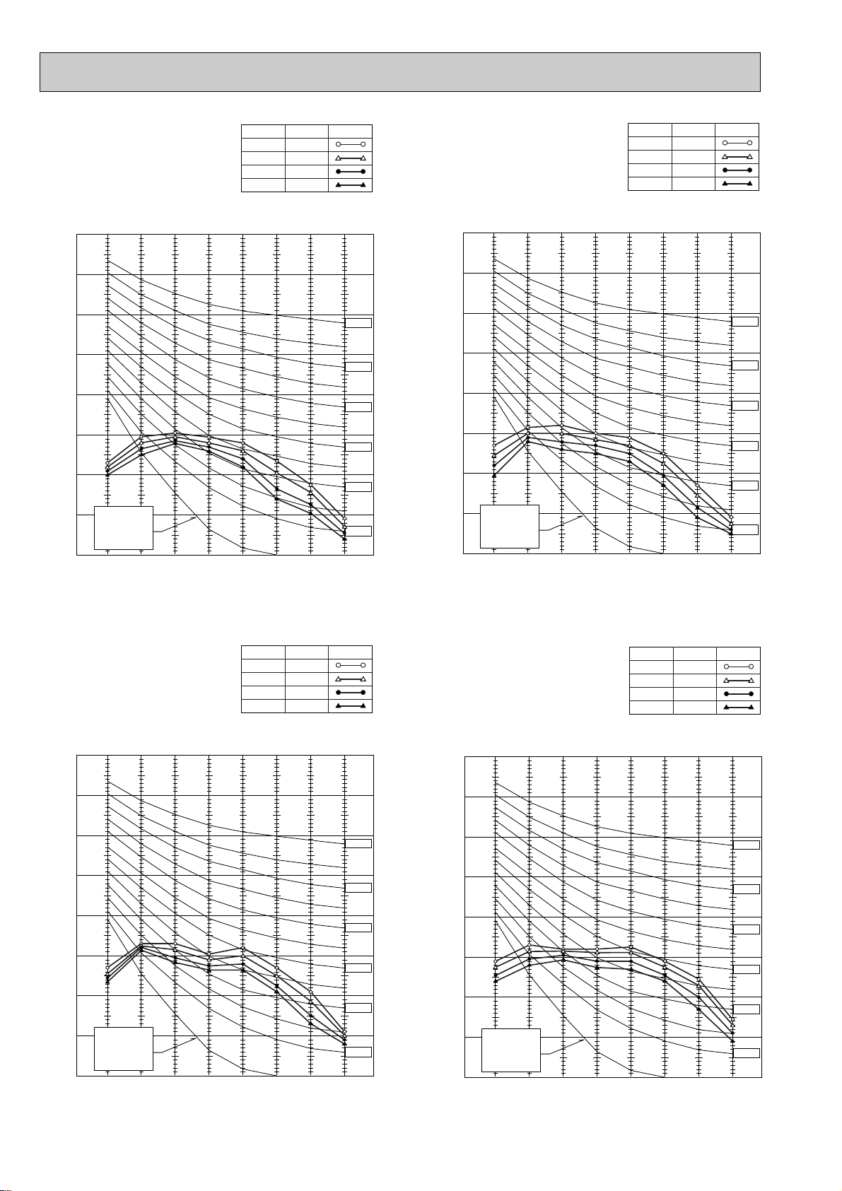
PCA-RP50GA
PCH-P50GAH
NOTCH
High
Medium1
Medium2
Low
SPL(dB)
42
40
38
37
LINE
PCA-RP60GA
PCA-RP71GA
PCH-P60GAH
PCH-P71GAH
NOTCH
High
Medium1
Medium2
Low
SPL(dB)
43
41
39
37
LINE
OCTAVE BAND SOUND PRESSURE LEVEL, dB (0 dB = 0.0002 µbar)
90
80
70
60
50
40
30
APPROXIMATE
20
THRESHOLD OF
HEARING FOR
CONTINUOUS
NOISE
10
63 125 250 500 1000 2000 4000 8000
BAND CENTER FREQUENCIES, Hz
NC-70
NC-60
NC-50
NC-40
NC-30
NC-20
OCTAVE BAND SOUND PRESSURE LEVEL, dB (0 dB = 0.0002 µbar)
90
80
70
60
50
40
30
APPROXIMATE
20
THRESHOLD OF
HEARING FOR
CONTINUOUS
NOISE
10
63 125 250 500 1000 2000 4000 8000
BAND CENTER FREQUENCIES, Hz
NC-70
NC-60
NC-50
NC-40
NC-30
NC-20
PCA-RP100GA
PCH-P100GAH
90
80
70
60
50
40
30
OCTAVE BAND SOUND PRESSURE LEVEL, dB (0 dB = 0.0002 µbar)
APPROXIMATE
20
THRESHOLD OF
HEARING FOR
CONTINUOUS
NOISE
10
63 125 250 500 1000 2000 4000 8000
NOTCH
High
Medium1
Medium2
Low
BAND CENTER FREQUENCIES, Hz
SPL(dB)
45
43
41
40
LINE
NC-70
NC-60
NC-50
NC-40
NC-30
NC-20
PCA-RP125GA
PCH-P125GAH
90
80
70
60
50
40
30
OCTAVE BAND SOUND PRESSURE LEVEL, dB (0 dB = 0.0002 µbar)
APPROXIMATE
20
THRESHOLD OF
HEARING FOR
CONTINUOUS
NOISE
10
63 125 250 500 1000 2000 4000 8000
NOTCH
High
Medium1
Medium2
Low
BAND CENTER FREQUENCIES, Hz
SPL(dB)
46
45
43
41
LINE
NC-70
NC-60
NC-50
NC-40
NC-30
NC-20
98

PCA-RP140GA
PCH-P140GAH
90
80
NOTCH
High
Medium1
Medium2
Low
SPL(dB)
48
46
44
42
LINE
OCTAVE BAND SOUND PRESSURE LEVEL, dB (0 dB = 0.0002 µbar)
1m
70
60
50
40
30
APPROXIMATE
20
THRESHOLD OF
HEARING FOR
CONTINUOUS
NOISE
10
63 125 250 500 1000 2000 4000 8000
BAND CENTER FREQUENCIES, Hz
1m
about 1.4m
NC-70
NC-60
NC-50
NC-40
NC-30
NC-20
ceiling
unit
MICROPHONE
99

PCA-RP71HA
NOTCH
High
Low
SPL(dB)
38
34
LINE
PCA-RP125HA
NOTCH
High
Low
SPL(dB)
50
44
LINE
OCTAVE BAND SOUND PRESSURE LEVEL, dB re 0.0002 µBAR
90
80
70
60
50
40
30
APPROXIMATE
20
TERESHOLD OF
HEARING FOR
CONTINUOUS
NOISE
10
63 125 250 500 1000 2000 4000 8000
BAND CENTER FREQUENCIES, Hz
NC-70
NC-60
NC-50
NC-40
NC-30
NC-20
OCTAVE BAND SOUND PRESSURE LEVEL, dB re 0.0002 µBAR
90
80
70
60
50
40
30
APPROXIMATE
20
TERESHOLD OF
HEARING FOR
CONTINUOUS
NOISE
10
63 125 250 500 1000 2000 4000 8000
BAND CENTER FREQUENCIES, Hz
NC-70
NC-60
NC-50
NC-40
NC-30
NC-20
1m
1m
about 1.4m
MICROPHONE
ceiling
unit
100
 Loading...