

Mitsubishi PKA-RP71KAL.TH, PKA-RP60KAL.TH-ER, PKA-RP71KAL.TH-ER, PKA-RP71KALR1.TH, PKA-RP71KALR1.TH-ER Servise Manual
...
SERVICE MANUAL
Note:
•
This manual describes only
service data of the indoor units.
• RoHS compliant products
have <G> mark on the spec
name plate.
CONTENTS
1. REFERENCE MANUAL
...................................
2
2. SAFETY PRECAUTION
...................................
3
3. PARTS NAMES AND FUNCTIONS
.................
4
4. SPECIFICATIONS
............................................
6
5. NOISE CRITERION CURVES
..........................
7
6. OUTLINES AND DIMENSIONS
.......................
8
7. WIRING DIAGRAM
..........................................
9
8. REFRIGERANT SYSTEM DIAGRAM
............
10
9. TROUBLESHOOTING
....................................
11
10. SPECIAL FUNCTION
.....................................
27
11. DISASSEMBLY PROCEDURE
.......................
30
Indoor unit
[Model Name] [Service Ref.]
WIRELESS REMOTE
CONTROLLER
ON/OFF TEMP
PARTS CATALOG (OCB452)
INDOOR UNIT
PKA-RP60KAL.TH
PKA-RP60KAL.TH-ER
PKA-RP60KALR1.TH
PKA-RP60KALR1.TH-ER
PKA-RP71KAL.TH
PKA-RP71KAL.TH-ER
PKA-RP71KALR1.TH
PKA-RP71KALR1.TH-ER
PKA-RP100KAL.TH
PKA-RP100KAL.TH-ER
PKA-RP100KALR1.TH
PKA-RP100KALR1.TH-ER
• Please void OCH452
REVISED EDITION-A.
PKA-RP60KAL
PKA-RP71KAL
PKA-RP100KAL
Revision:
• Added
PKA-RP60KAL.TH-ER,
PKA-RP60KALR1.TH,
PKA-RP60KALR1.TH-ER,
PKA-RP71KAL.TH-ER,
PKA-RP71KALR1.TH,
PKA-RP71KALR1.TH-ER,
PKA-RP100KAL.TH-ER,
PKA-RP100KALR1.TH
and
PKA-RP100KALR1.TH-ER
in
REVISED EDITION-B.
• Some descriptions have been
modified.
SPLIT-TYPE, HEAT PUMP AIR CONDITIONERS
SPLIT-TYPE, AIR CONDITIONERS
No. OCH452
REVISED EDITION-B
July 2014
2
1
REFERENCE MANUAL
Service Ref.Mdel Name
Service Manual No.
PUHZ-P200/250YHA3
OCH424/ OCB424
PUHZ-RP35/50/60/71VHA4
PUHZ-RP100/125/140VKA
PUHZ-RP100/125/140/200/250YKA
OCH451
OCB451
PU(H)-P71/100VHA#2.UK
PU(H)-P71/100/125/140YHA#2.UK
OC379
PUHZ-HRP100VHA2
PUHZ-HRP100YHA2
OCH425
OCB425
OCH415
OCB415
PUHZ-P100/125/140VHA3.UK
PUHZ-P200/250YHA3
PUHZ-ZRP60/71VHAPUHZ-ZRP60/71VHA
PUHZ-RP35/50/60/71VHA4
PUHZ-RP100/125/140VKA
PUHZ-RP100/125/140/200/250YKA
PU(H)-P71/100VHA
PU(H)-P71/100/125/140YHA
PUHZ-HRP100VHA2
PUHZ-HRP100YHA2
PUHZ-ZRP100VKA2.UK
PUHZ-ZRP100YKA2.UK
PUHZ-ZRP100VKA2
PUHZ-ZRP100YKA2
PUHZ-P100VHA4.UK
PUHZ-P100YHA2.UK
PUHZ-P100VHA4
PUHZ-P100YHA2
PUHZ-P100/125/140VHA3
OCH527/ OCB527
OCH568
OCB568
OUTDOOR UNIT’S SERVICE MANUAL
TECHNICAL CHANGES
Service ref. have been changed as follows.
PKA-RP60KAL PKA-RP60KALR1
PKA-RP71KAL
PKA-RP71KALR1
PKA-RP100KAL
PKA-RP100KALR1
• S/W (for dual set temperature) has been changed.
OCH452B
3
SAFETY PRECAUTION
2
Cautions for units utilising refrigerant R410A
2-2. CAUTIONS RELATED TO NEW REFRIGERANT
Use new refrigerant pipes.
Make sure that the inside and outside of refrigerant piping is clean and it has no contamination
such as sulfur hazardous for use, oxides, dirt,
shaving particles, etc.
In addition, use pipes with specified thickness.
In case of using the existing pipes for R22, be careful with
the following:
· For RP100, 125 and 140, be sure to perform replace ment operation before test run.
· Change flare nut to the one provided with this product.
Use a newly flared pipe.
· Avoid using thin pipes.
Charge refrigerant from liquid phase of gas
cylinder.
If the refrigerant is charged from gas phase, composition
change may occur in refrigerant and the efficiency will be
lowered.
Do not use refrigerant other than R410A.
If other refrigerant (R22, etc.) is used, chlorine in refrigerant can cause deterioration of refrigerant oil, etc.
Use a vacuum pump with a reverse flow check
valve.
Vacuum pump oil may flow back into refrigerant cycle and
that can cause deterioration of refrigerant oil, etc.
Use the following tools specifically designed for
use with R410A refrigerant.
The following tools are necessary to use R410A refrigerant.
Handle tools with care.
If dirt, dust or moisture enters into refrigerant cycle, that can
cause deterioration of refrigerant oil or malfunction of compressor.
Do not use a charging cylinder.
If a charging cylinder is used, the composition of refrigerant will change and the efficiency will be lowered.
Flare tool
Electronic refrigerant
charging scale
Vacuum pump adaptor
Size adjustment gauge
Gauge manifold
Torque wrench
Gas leak detector
Charge hose
Tools for R410A
Contamination inside refrigerant piping can cause deterioration of refrigerant oil, etc.
Ventilate the room if refrigerant leaks during
operation. If refrigerant comes into contact with
a flame, poisonous gases will be released.
Use the specified refrigerant only.
Never use any refrigerant other than that specified.
Doing so may cause a burst, an explosion, or fire when the
unit is being used, serviced, or disposed of.
Correct refrigerant is specified in the manuals and on the
spec labels provided with our products.
We will not be held responsible for mechanical failure,
system malfunction, unit breakdown or accidents caused
by failure to follow the instructions.
Store the piping indoors, and both ends of the
piping sealed until just before brazing.
(Leave elbow joints, etc. in their packaging.)
If dirt, dust or moisture enters into refrigerant cycle, that can
cause deterioration of refrigerant oil or malfunction of compressor.
The refrigerant oil applied to flare and flange
connections must be ester oil, ether oil or
alkylbenzene oil in a small amount.
If large amount of mineral oil enters, that can cause deterioration of refrigerant oil, etc.
2-1. ALWAYS OBSERVE FOR SAFETY
Before obtaining access to terminal, all supply
circuits must be disconnected.
OCH452B
4
Gravimeter
Unit
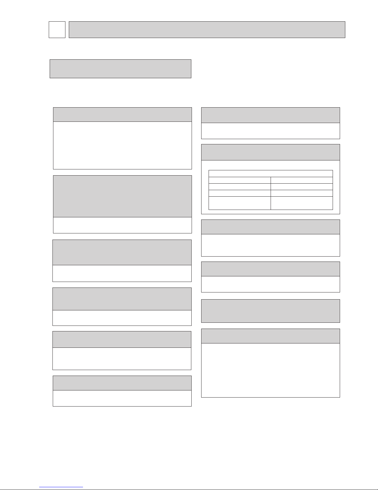
[3] Service tools
Use the below service tools as exclusive tools for R410A refrigerant.
3
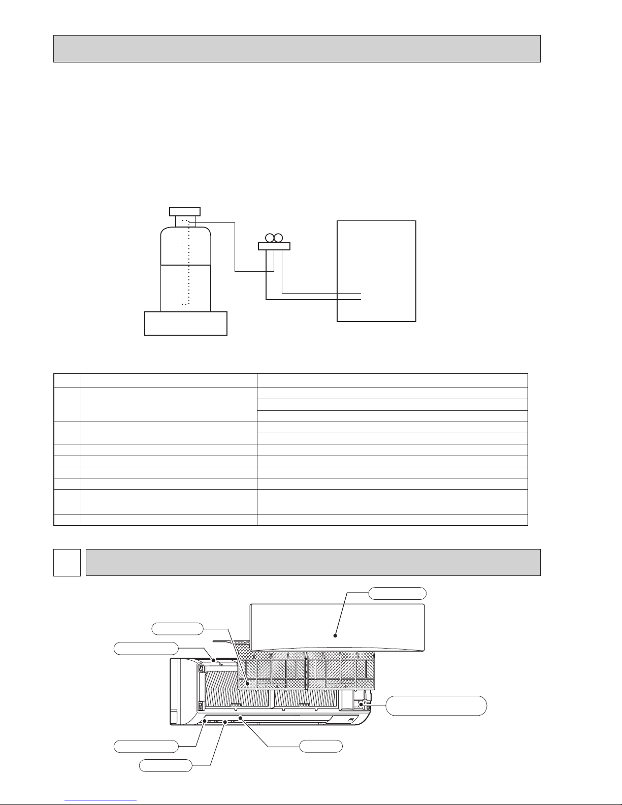
PARTS NAMES AND FUNCTIONS
Emergency
operation
switch
Front grille
Air inlet
Filter
Air outlet
Louver
Vane
3-1. Indoor unit
No.
Tool name Specifications
1
Gauge manifold · Only for R410A
· Use the existing fitting
specifications
. (UNF1/2)
· Use high-tension side pressure of 5.3MPa·G or over.
2
Charge hose · Only for R410A
· Use pressure performance of 5.09MPa·G or over.
3
Electronic scale
—
4
Gas leak detector · Use the detector for R134a, R407C or R410A.
5
Adaptor for reverse flow check · Attach on vacuum pump.
6
Refrigerant charge base
—
7
Refrigerant cylinder · Only for R410A · Top of cylinder (Pink)
· Cylinder with syphon
8
Refrigerant recovery equipment
—
[1] Cautions for service
(1) Perform service after recovering the refrigerant left in unit completely.
(2) Do not release refrigerant in the air.
(3) After completing service, charge the cycle with specified amount of refrigerant.
(4) When performing service, install a filter drier simultaneously.
Be sure to use a filter drier for new refrigerant.
[2] Additional refrigerant charge
When charging directly from cylinder
· Check that cylinder for R410A on the market is syphon type.
· Charging should be performed with the cylinder of syphon stood vertically. (Refrigerant is charged from liquid phase.)
OCH452B
5
ON/OFF TEMP
FAN
VANE
TEST RUN
AUTO STOP
AUTO START
h
min
LOUVER
MODE
CHECK
RESETSET CLOCK
MODEL SELECT
NOT AVAILABLE
CHECK
TEST RUN
°C
AMPM
AMPM
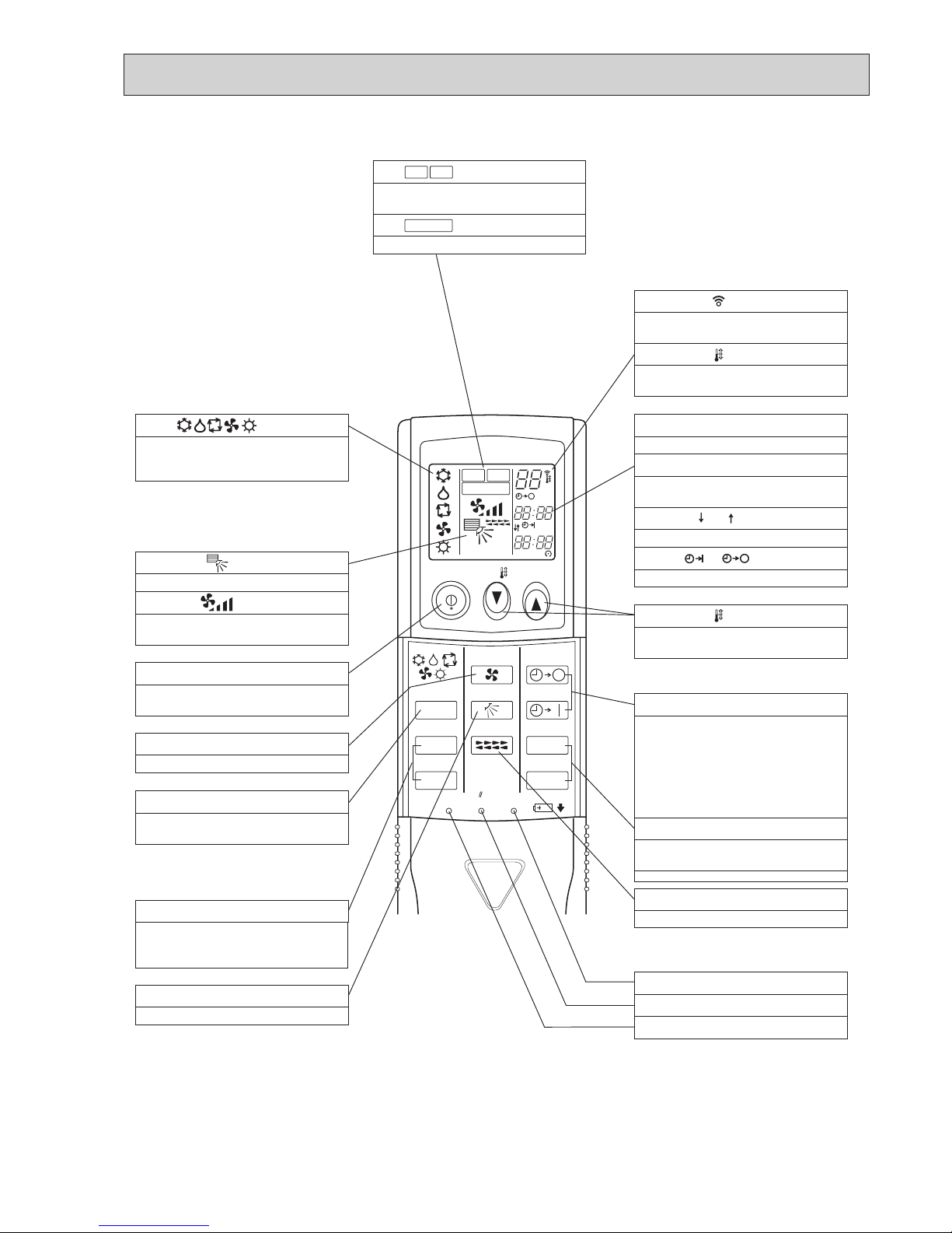
VANE CONTROL button
Used to change the air flow direction.
CLOCK button
RESET button
SET button
ON/OFF button
The unit is turned ON and OFF alternately
each time
the button is pressed.
MODE SELECT button
Used to switch the operation mode between
cooling, drying, heating, auto and fan mode.
CHECK-TEST RUN buttons
Only press this button to perform an
inspection check or test operation.
Do not use it for normal operation.
FAN SPEED SELECT button
Used to change the fan speed.
TIMER display
Displays when in timer operation or when
setting timer.
buttons
SET TEMPERATURE button sets any desired
room temperature.
CLOCK display
Displays the current time.
“ ” “ ” display
Displays the order of timer operation.
“ ” “ ” display
Displays whether timer is on or off.
Buttons used to set the “hour and minute” of
the current time and timer settings.
“h” and “min” buttons
display
display
FAN SPEED display indicates which fan
speed has been selected.
display
The vertical direction of air flow is indicated.
display
Blinks when model is selected.
display
display
CHECK and TEST RUN display indicate that
the unit is being checked or test-run.
display
OPERATION MODE display
Operation mode display indicates which
operation mode is in effect.
AUTO STOP (OFF timer): when this switch
is set, the air conditioner will be
automatically stopped at the preset time.
AUTO START (ON timer): when this switch is
set, the air conditioner will be automatically
started at the preset time.
MODEL SELECT
CHECK
TEST RUN
LOUVER button
Changes left/right airflow direction.
(Not available for this model.)
SET TEMP. display indicates the desired
temperature which is set.
Lights up while the signal is transmitted to
the indoor unit when the button is pressed.
TIMER CONTROL buttons
3-2. Wireless remote controller
OCH452B

6
SPECIFICATIONS
4
Cooling
0.06
0.43
Heating
0.05
0.36
Single phase, 50Hz, 230V
Munsell 1.0Y 9.2/0.2
Plate fin coil
Line flow fan (direct) o 1
0.056
18-20-22 (635-705-780)
0 (direct blow)
–
Wireless remote controller & built-in
39-42-45
16 (5/8)
1,170 (46-1/16)
295 (11-5/8)
365 (14-3/8)
21 (46)
kW
A
kW
K/min (CFM)
Pa (mmAq)
kW
dB
mm (in)
mm (in)
mm (in)
mm (in)
kg (lb)
Mode
Power supply (phase, cycle, voltage)
Input
Running current
External finish (Panel)
Heat exchanger
Fan Fan (drive) o No.
Fan motor output
Airflow (Low-Middle-High)
External static pressure
Booster heater
Operation control & Thermostat
Noise level (Low-Middle-High)
Field drain pipe I.D.
Dimensions
Weight
W
D
H
INDOOR UNIT
Service Ref.
PKA-RP71KAL.TH
PKA-RP71KAL.TH-ER
PKA-RP71KALR1.TH
PKA-RP71KALR1.TH-ER
Cooling
0.06
0.43
Heating
0.05
0.36
Single phase, 50Hz, 230V
Munsell 1.0Y 9.2/0.2
Plate fin coil
Line flow fan (direct) o 1
0.056
18-20-22 (635-705-780)
0 (direct blow)
–
Wireless remote controller & built-in
39-42-45
16 (5/8)
1,170 (46-1/16)
295 (11-5/8)
365 (14-3/8)
21 (46)
kW
A
kW
K/min (CFM)
Pa (mmAq)
kW
dB
mm (in)
mm (in)
mm (in)
mm (in)
kg (lb)
Mode
Power supply (phase, cycle, voltage)
Input
Running current
External finish (Panel)
Heat exchanger
Fan Fan (drive) o No.
Fan motor output
Airflow (Low-Middle-High)
External static pressure
Booster heater
Operation control & Thermostat
Noise level (Low-Middle-High)
Field drain pipe I.D.
Dimensions
Weight
W
D
H
INDOOR UNIT
PKA-RP60KAL.TH
PKA-RP60KAL.TH-ER
PKA-RP60KALR1.TH
PKA-RP60KALR1.TH-ER
Service Ref.
Cooling
0.08
0.57
Heating
0.07
0.50
Single phase, 50Hz, 230V
Munsell 1.0Y 9.2/0.2
Plate fin coil
Line flow fan (direct) o 1
0.056
20-23-26 (705-810-920)
0 (direct blow)
–
Wireless remote controller & built-in
41-45-49
16 (5/8)
kW
A
kW
K/min (CFM)
Pa (mmAq)
kW
dB
mm (in)
mm (in)
mm (in)
mm (in)
kg (lb)
W
D
H
INDOOR UNIT
PKA-RP100KAL.TH
PKA-RP100KAL.TH-ER
PKA-RP100KALR1.TH
PKA-RP100KALR1.TH-ER
Mode
Power supply (phase, cycle, voltage)
Input
Running current
External finish (Panel)
Heat exchanger
Fan Fan (drive) o No.
Fan motor output
Airflow (Low-Middle-High)
External static pressure
Booster heater
Operation control & Thermostat
Noise level (Low-Middle-High)
Field drain pipe I.D.
Dimensions
Weight
1,170 (46-1/16)
295 (11-5/8)
365 (14-3/8)
21(46)
Service Ref.
OCH452B
7
5
NOISE CRITERION CURVES
* Measured in anechoic room.
PKA-RP100KAL
41 - 45 - 49
PKA-RP60/71KAL
Models
39 - 42 - 45
Sound level dB (A)
Sound level at anechoic room : Low-Middle-High
1.0m
1.0m
Measurement location
5-1. SOUND LEVELS
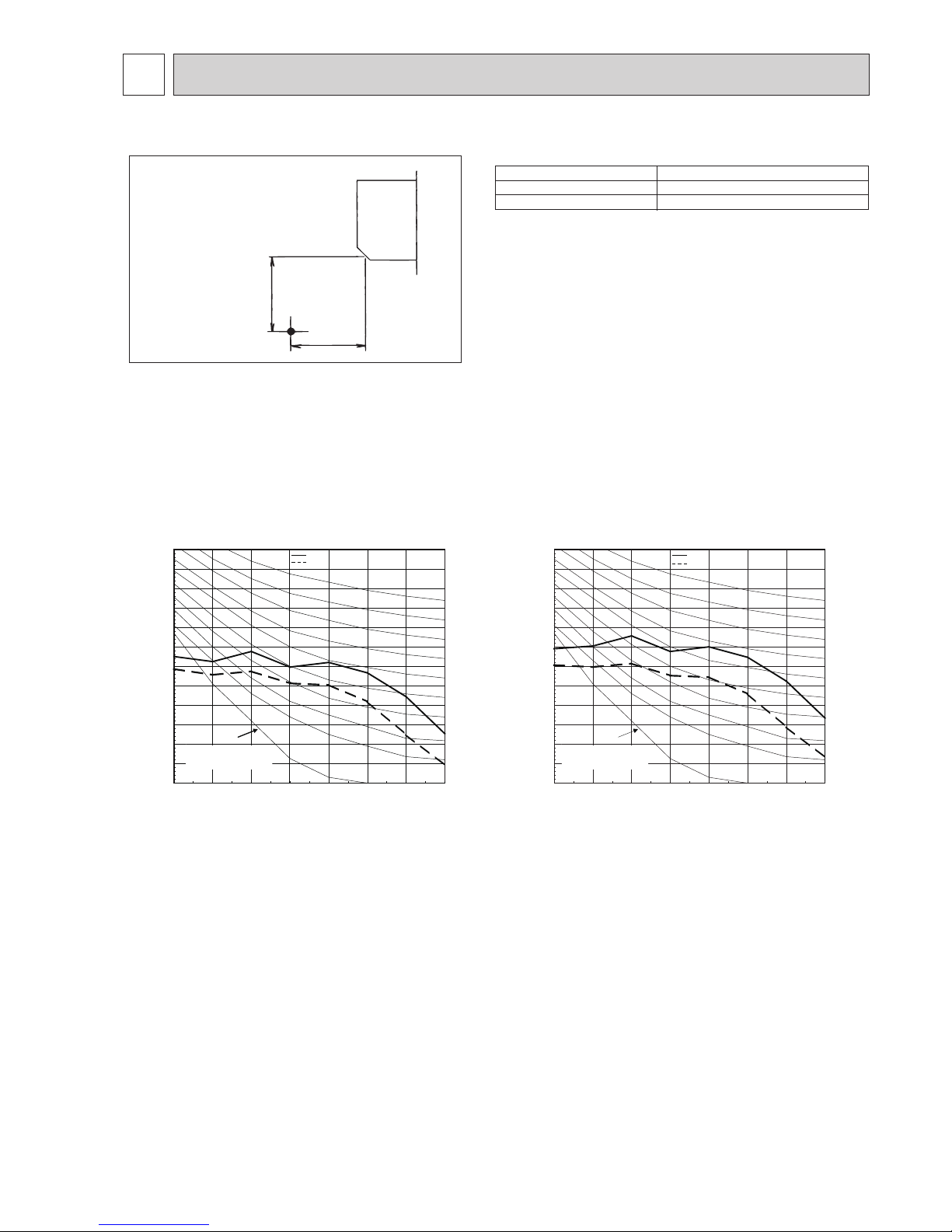
5-2. NOISE CRITERION CURVES
PKA-RP60/71KAL.TH(-ER)
External static pressure : 0Pa
Power source :
220, 230, 240V, 50Hz
PKA-RP100KAL.TH(-ER)
External static pressure : 0Pa
Power source :
220, 230, 240V, 50Hz
10.0
15.0
20.0
25.0
30.0
35.0
40.0
45.0
50.0
55.0
60.0
65.0
70.0
63 125 250 500 1k 2k 4k 8k
NC-60
NC-50
Octave band pressure level (dB) 0dB=20μPa
Approximate minimum
audible limit on
continuous noise
NC-40
Octave band center frequencies (Hz)
NC-20
NC-30
High
Low
10.0
15.0
20.0
25.0
30.0
35.0
40.0
45.0
50.0
55.0
60.0
65.0
70.0
63 125 250 500 1k 2k 4k 8k
NC-60
NC-50
Octave band pressure level (dB) 0dB=20μPa
NC-40
Octave band center frequencies (Hz)
NC-20
NC-30
High
Low
PKA-RP60/71KALR1.TH(-ER)
PKA-RP100KALR1.TH(-ER)
Approximate minimum
audible limit on
continuous noise
OCH452B

8
Refrigerant pipe : 9.52
Flared connection : 3/8F
16 O.D
Liquid pipe
Gas pipe
Drain hose
Sleeve
(purchased locally)
75
75~ 80
Through hole
53
32
18
30
66
35
65.2
423.7
1170
123
154
B
B
134
431.7
11
140.3
365
A
5
C
295
75-Φ5.1
Tapping screw hole
4-Φ9 Bolt hole
Center measurement hole Φ2.5
0
314
364
384
408.5
439
454
517.4
585
439
384
339
189
0
216.5
R37.5
339
384
585
439
349.2
449.2
430.5
530.5
110
110
314
54
15.5
0
50
75
117
125
142
292
279.5
242
192
25
100
32
25
37.5
62.5
104.5
129.5
167
217
264
292
308.5
311
0
12.5
12.5
87.5
229.5
364
384.5
408.5
439
454
465.5
60
60
01010
54
3
C
65
67
65
67
77
77
7.8
7.8
10.7
87
77
65
B A
Top side
Front side
Front side (Grille open)
Terminal block for outdoor unit
Terminal block for power supply (option)
Terminal block for
MA-remote controller (option)
Emergency operation switch
(cooling/heating)
Operation lamp
DEFROST/STAND BY lamp
Receiver
Knockout hole for
right piping
Mount board
Right side
444 (Gas pipe)
482 (Liquid pipe)
585 (Drain hose)
Filter hook
Under side
Vane (auto)
Knockout hole
for lower piping
Louver (manual)
Piping connection department
Indoor unit outline
Wall hole for
right rear piping
Knockout hole for
left rear piping
(75×480)
Wall hole for
left rear piping
Mount board
Temporarily fixing hole
108 mm or greater with left or
rear left piping or
drain pump installation
Min. 48
Min. 250
Air outlet
Air inlet
Min. 100.5
Min. 220Min. 52.3
550 mm or greater with optional
drain pump installation
265 mm or greater with optional
drain pump installation
Min. 7
Required space (Indoor unit)
Knockout hole for piping
Knockout hole
for left piping
Left side
Refrigerant pipe : 15.88
Flared connection : 5/8F
74
(855)
241
OUTLINES AND DIMENSIONS
6
PKA-RP60KAL.TH PKA-RP71KAL.TH PKA-RP100KAL.TH
PKA-RP60KAL.TH-ER PKA-RP71KAL.TH-ER PKA-RP100KAL.TH-ER
PKA-RP60KALR1.TH PKA-RP71KALR1.TH PKA-RP100KALR1.TH
PKA-RP60KALR1.TH-ER PKA-RP71KALR1.TH-ER PKA-RP100KALR1.TH-ER
Unit: mm
OCH452B
9
WIRING DIAGRAM
7
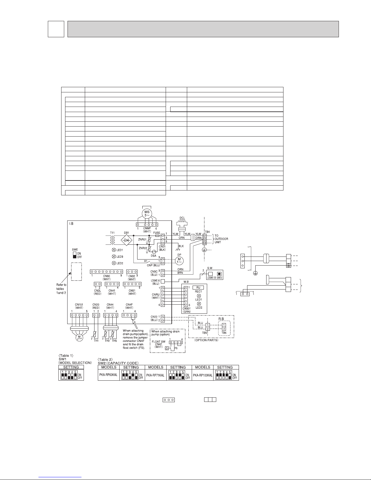
SYMBOL SYMBOLNAME NAME
I.B
R.B
Indoor controller board
FUSE (T3.15AL250V)
Varistor
Surge absorber
Connector (LOSSNAY)
Connector (Remote switch)
Connector (HA terminal-A)
Connector (Centrally control)
Power supply (I.B)
Power supply (R.B)
Transmission (Indoor-outdoor)
Relay (Drain pump(option))
Switch (Model selection) wSee table 1
Switch (Capacity code) wSee table 2
Connector (Emergency operation)
Vane motor
Fan motor
DRAIN PUMP (OPTION)
DRAIN FLOAT SWITCH (OPTION)
Terminal block (Indoor unit Power (option))
Terminal block (Indoor/outdoor connecting line (option))
Terminal block (Remote controller transmission line)
REACTOR
Room temp. Thermistor
(0: / 15k", 25: / 5. 4k" Detect)
Pipe temp. Thermistor/liquid
(0: / 15k", 25: / 5. 4k" Detect)
Cond. / eva. temp. Thermistor
(0: / 15k", 25: / 5. 4k" Detect)
M
FUSE
MS
Switch board
S.W
Emergency operation
SWE2
ZNR01,02
Drain pump (option) power supply
(Sold separately:Drain pump(option))
CNP
DSA
DP
CN2L
FS
CN32
TB2
CN41
CN51
Connector (Remote operation adapter)
CN90
TB4
DCL
LED1
TB5
LED2
TH1
LED3
X1
Drain float switch (Sold separately:Drain pump (option))
CN4F
Wired remote controller (option)
Terminal block (Remote controller transmission line)
TB6
TH2
SW1
TH5
SW2
SWE
[LEGEND]
TO OUTDOOR
UNIT
5
3
1
31
CN01
(BLK)
ORN
YLW
BLU
RED
GRN/YLW
I.B
w1(Fig. 1)
I.B
TB2
POWER SUPPLY
~(1PHASE)
230V 50Hz
ORN
ORN
YLW
BRN
TB4
INDOOR/OUTDOOR
COMMUNICATION
CN3C (BLU)
L
N
S1
S2
S3
W.B
REC1
LED1
LED2
PCB for wireless remote controller
Receiving unit
LED (Operation indication : Green)
LED (Preparation for heating : Orange)
1. SymboIs used in wiring diagram above are, :Connector, : Terminal (block).
2. Indoor and outdoor connecting wires have poIarities, make sure to match terminal numbers
(S1, S2, S3) for correct wirings.
3. Since the outdoor side electric wiring may change, be sure to check the outdoor unit electric
wiring diagram for servicing.
4. This diagram shows the wiring of indoor and outdoor connecting wires.(specification of 230V),
adopting superimposed system of power and signal.
w1 When work to Supply power separately to indoor and outdoor units was applied,refer to Fig 1.
w2 For power supply system of this unit, refer to the caution label located near this diagram.
Notes:
MF
The black square (■) indicates a switch position.
PKA-RP60KAL.TH PKA-RP71KAL.TH PKA-RP100KAL.TH
PKA-RP60KAL.TH-ER PKA-RP71KAL.TH-ER PKA-RP100KAL.TH-ER
PKA-RP60KALR1.TH PKA-RP71KALR1.TH PKA-RP100KALR1.TH
PKA-RP60KALR1.TH-ER PKA-RP71KALR1.TH-ER PKA-RP100KALR1.TH-ER
OCH452B

10
Thermistor TH2
(Pipe temperature/ liquid)
Distributor
with strainer (#50/#100)
Thermistor TH5
(Cond./ Eva. temperature)
Thermistor TH1
(Room temperature)
Refrigerant flow in cooling
Refrigerant flow in heating
Strainer (#50)
Strainer (#50)
Heat exchanger
Refrigerant GAS pipe connection
(Flare)
Refrigerant LIQUID pipe connection
(Flare)
REFRIGERANT SYSTEM DIAGRAM
8
PKA-RP60KAL.TH PKA-RP71KAL.TH PKA-RP100KAL.TH
PKA-RP60KAL.TH-ER PKA-RP71KAL.TH-ER PKA-RP100KAL.TH-ER
PKA-RP60KALR1.TH PKA-RP71KALR1.TH PKA-RP100KALR1.TH
PKA-RP60KALR1.TH-ER PKA-RP71KALR1.TH-ER PKA-RP100KALR1.TH-ER
OCH452B
11
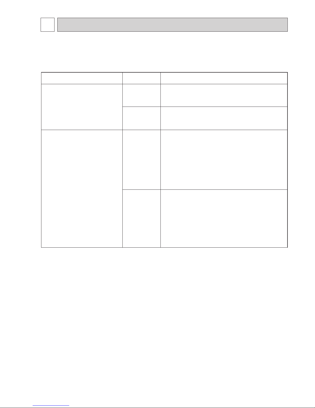
<Check code displayed by self-diagnosis and actions to be taken for service (summary)>
Present and past check codes are logged, and they can be displayed on the wired remote controller or controller board of outdoor unit. Actions to be taken for service, which depends on whether or not the trouble is reoccurring in the field, are summarized in the table below. Check the contents below before investigating details.
9-1. TROUBLESHOOTING
Unit conditions at service
Check code
Actions to be taken for service (summary)
The trouble is reoccurring.
Displayed
Not displayed
Judge what is wrong and take a corrective action according
to “9-3. SELF-DIAGNOIS ACTION TABLE”.
Conduct troubleshooting and ascertain the cause of the
trouble according to “9-4. TROUBLESHOOTING BY
INFERIOR PHENOMENA”.
The trouble is not reoccurring.
Logged
Not logged
1Consider the temporary defects such as the work of
protection devices in the refrigerant circuit including
compressor, poor connection of wiring, noise, etc.
Re-check the symptom, and check the installation
environment, refrigerant amount, weather when the
trouble occurred, matters related to wiring, etc.
2Reset check code logs and restart the unit after finishing
service.
3There is no abnormality in electrical component,
controller board, remote controller, etc.
1Re-check the abnormal symptom.
2Conduct troubleshooting and ascertain the cause of the
trouble
according to “9-4.
TROUBLESHOOTING BY
INFERIOR PHENOMENA”.
3Continue to operate unit for the time being if the cause
is not ascertained.
4There is no abnormality concerning of parts such as
electrical component, controller board, remote
controller, etc.
TROUBLESHOOTING
9
OCH452B
 Loading...