

Mitsubishi PKA-RP35HAL, PKA-RP50HAL Service Manual

SPLIT-TYPE, HEAT PUMP AIR CONDITIONERS
SPLIT-TYPE, AIR CONDITIONERS
SERVICE MANUAL
Indoor unit
[Model names] [Service Ref.]
PKA-RP35HAL
PKA-RP50HAL
PKA-RP35HAL
PKA-RP50HAL
March 2009
No. OCH453
NOTE:
• This manual describes
only service data of the
indoor units.
• RoHS compliant products
have <G> mark on the
spec name plate.
INDOOR UNIT
CONTENTS
1. REFERENCE MANUAL
2. SAFETY PRECAUTION
3. PART NAMES AND FUNCTIONS
4. SPECIFICATIONS
5. NOISE CRITERION CURVES
6. OUTLINES AND DIMENSIONS
7. WIRING DIAGRAM
8. REFRIGERANT SYSTEM DIAGRAM
9. TROUBLESHOOTING
10. SPECIAL FUNCTION
11. DISASSEMBLY PROCEDURE
...................................
...................................
...................
............................................
..........................
.......................
..........................................
....................................
.....................................
.......................
PARTS CATALOG (OCB453)
............
2
3
4
6
7
8
9
10
11
26
29

1
REFERENCE MANUAL
OUTDOOR UNIT’S SERVICE MANUAL
Service Ref.
PUHZ-RP35/50/60/71VHA4
PUHZ-RP100/125/140VKA
PUHZ-RP100/125/140/200/250YKA
PU(H)-P71/100VHA#2.UK
PU(H)-P71/100/125/140YHA#2.UK
PUHZ-P100/125/140VHA3.UK
PUHZ-P200/250YHA3
PUHZ-HRP71/100VHA2
PUHZ-HRP100/125YHA2
Service Manual No.
OCH451
OCB451
OC379
OCH415/OCB415
OCH424/OCB424
OCH425/OCB425
2

2
SAFETY PRECAUTION
2-1. ALWAYS OBSERVE FOR SAFETY
Before obtaining access to terminal, all supply
circuits must be disconnected.
2-2. CAUTIONS RELATED TO NEW REFRIGERANT
Cautions for units utilising refrigerant R410A
Use new refrigerant pipes.
In case of using the existing pipes for R22, be careful with
the followings.
· For RP100, 125 and 140, be sure to perform replace ment operation before test run.
· Change flare nut to the one provided with this product.
Use a newly flared pipe.
· Avoid using thin pipes.
Make sure that the inside and outside of refrigerant piping is clean and it has no contamination
such as sulfur hazardous for use, oxides, dirt,
shaving particles, etc.
In addition, use pipes with specified thickness.
Contamination inside refrigerant piping can cause deterioration of refrigerant oil etc.
Store the piping to be used indoors during
installation, and keep both ends of the piping
sealed until just before brazing. (Leave elbow
joints, etc. in their packaging.)
If dirt, dust or moisture enters into refrigerant cycle, that can
cause deterioration of refrigerant oil or malfunction of compressor.
Do not use refrigerant other than R410A.
If other refrigerant (R22 etc.) is used, chlorine in refrigerant can cause deterioration of refrigerant oil etc.
Use a vacuum pump with a reverse flow check
valve.
Vacuum pump oil may flow back into refrigerant cycle and
that can cause deterioration of refrigerant oil etc.
Use the following tools specifically designed for
use with R410A refrigerant.
The following tools are necessary to use R410A refrigerant.
Tools for R410A
Gauge manifold
Charge hose
Gas leak detector
Torque wrench
Flare tool
Size adjustment gauge
Vacuum pump adaptor
Electronic refrigerant
charging scale
Handle tools with care.
If dirt, dust or moisture enters into refrigerant cycle, that can
cause deterioration of refrigerant oil or malfunction of compressor.
Use ester oil, ether oil or alkylbenzene oil (small
amount) as the refrigerant oil applied to flares
and flange connections.
If large amount of mineral oil enters, that can cause deterioration of refrigerant oil etc.
Do not use a charging cylinder.
If a charging cylinder is used, the composition of refrigerant will change and the efficiency will be lowered.
Ventilate the room if refrigerant leaks during
Charge refrigerant from liquid phase of gas
cylinder.
If the refrigerant is charged from gas phase, composition
change may occur in refrigerant and the efficiency will be
lowered.
operation. If refrigerant comes into contact with
a flame, poisonous gases will be released.
[1] Cautions for service
(1) Perform service after recovering the refrigerant left in unit completely.
(2) Do not release refrigerant in the air.
(3) After completing service, charge the cycle with specified amount of refrigerant.
(4) When performing service, install a filter drier simultaneously.
Be sure to use a filter drier for new refrigerant.
[2] Additional refrigerant charge
When charging directly from cylinder
· Check that cylinder for R410A on the market is syphon type.
· Charging should be performed with the cylinder of syphon stood vertically. (Refrigerant is charged from liquid phase.)
3

Unit
Gravimeter
[3] Service tools
Use the below service tools as exclusive tools for R410A refrigerant.
No. Tool name Specifications
1 Gauge manifold · Only for R410A
· Use the existing fitting
· Use high-tension side pressure of 5.3MPa·G or over.
2 Charge hose · Only for R410A
· Use pressure performance of 5.09MPa·G or over.
3 Electronic scale
4 Gas leak detector · Use the detector for R134a, R407C or R410A.
5 Adaptor for reverse flow check · Attach on vacuum pump.
6 Refrigerant charge base
7 Refrigerant cylinder · Only for R410A · Top of cylinder (Pink)
· Cylinder with syphon
8 Refrigerant recovery equipment
specifications
. (UNF1/2)
3
PART NAMES AND FUNCTIONS
Indoor unit
Filter
Louver
Air outlet
Air intake
Vane
4

Wireless remote controller
CHECK
TEST RUN
display
CHECK and TEST RUN display indicate that
the unit is being checked or test-run.
MODEL SELECT
Blinks when model is selected.
display
display
Lights up while the signal is transmitted to
the indoor unit when the button is pressed.
display
SET TEMP. display indicates the desired
temperature which is set.
display
OPERATION MODE display
Operation mode display indicates which
operation mode is in effect.
display
The vertical direction of air flow is indicated.
display
FAN SPEED display indicates which fan
speed has been selected.
ON/OFF button
The unit is turned ON and OFF alternately
each time the button is pressed.
FAN SPEED SELECT button
Used to change the fan speed.
MODE SELECT button
Used to switch the operation mode between
cooling, drying, heating, auto and fan mode.
CHECK
TEST RUN
MODEL SELECT
NOT AVAILABLE
ON/OFF TEMP
FAN
MODE
CHECK
VAN E
LOUVER
TEST RUN
RESETSET CLOCK
°C
AMPM
AMPM
AUTO STOP
AUTO START
h
min
CLOCK display
Displays the current time.
TIMER display
Displays when in timer operation or when
setting timer.
“ ” “ ” display
Displays the order of timer operation.
“ ” “ ” display
Displays whether timer is on or off.
button
SET TEMPERATURE button sets any desired
room temperature.
TIMER CONTROL buttons
AUTO STOP (OFF timer): when this switch
is set, the air conditioner will be
automatically stopped at the preset time.
AUTO START (ON timer): when this switch is
set, the air conditioner will be automatically
started at the preset time.
h and min buttons
Buttons used to set the “hour and minute” of
the current time and timer settings.
CHECK-TEST RUN button
Only press this button to perform an
inspection check or test operation.
Do not use it for normal operation.
VANE CONTROL button
Used to change the air flow direction.
LOUVER button
Changes left/right airflow direction.
(Not available for this model.)
CLOCK button
RESET button
SET button
5

4
SPECIFICATIONS
Service Ref.
Mode
Power supply (phase, cycle, voltage)
Input
Running current
External finish (Panel)
Heat exchanger
Fan Fan (drive) % No.
Fan motor output
Airflow (Low-Middle-High)
External static pressure
Booster heater
INDOOR UNIT
Operation control & Thermostat
Noise level (Low-Middle-High)
Field drain pipe I.D.
Dimensions
Weight
*/min(CFM)
Pa(mmAq)
W
D
H
*/min(CFM)
Pa(mmAq)
W
D
H
kW
A
kW
kW
dB
mm(in.)
mm(in.)
mm(in.)
mm(in.)
kg(lbs)
kW
A
kW
kW
dB
mm(in.)
mm(in.)
mm(in.)
mm(in.)
kg(lbs)
Cooling
PKA-RP35HAL
Single phase, 50Hz, 230V
0.04
0.40
Munsell 1.0Y 9.2/0.2
Plate fin coil
Line flow fan (direct) % 1
0.030
9-10.5-12 (320-370-425)
0 (direct blow)
–
Wireless remote controller & built-in
36-40-43
16 (5/8)
898 (35-3/8)
249 (9-13/16)
295 (11-5/8)
13 (29)
PKA-RP50HAL
Cooling
Single phase, 50Hz, 230V
0.04
0.40
Munsell 1.0Y 9.2/0.2
Plate fin coil
Line flow fan (direct) % 1
0.030
9-10.5-12 (320-370-425)
0 (direct blow)
–
Wireless remote controller & built-in
36-40-43
16 (5/8)
898 (35-3/8)
249 (9-13/16)
295 (11-5/8)
13 (29)
Heating
0.03
0.30
Heating
0.03
0.30
6

5
A
)
NOISE CRITERION CURVES
5-1. SOUND LEVELS
1.0m
PKA-RP35, 50HAL
Sound level at anechoic room : Low-Middle-High
Sound level dB (A)
36 - 40 - 43
Measurement location
* Measured in anechoic room.
1.0m
5-2. NOISE CRITERION CURVES
Octave band pressure level (dB) 0dB=20μPa
70.0
65.0
60.0
55.0
50.0
45.0
40.0
35.0
30.0
25.0
20.0
15.0
pproximate minimum
audible limit on
continuous noise
High
NC-60
NC-50
NC-40
NC-30
NC-20
10.0
63 125 250 500 1k 2k 4k 8k
Octave band center frequencies(Hz
7
6
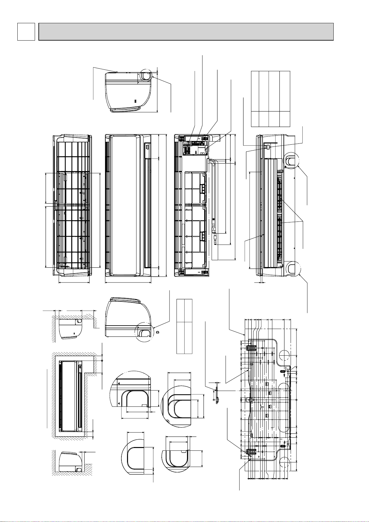
Min.7
250mm or greater with optional
drain pump installation.
Required space (Indoor unit)
Min.50
Min.220
Min.150
550mm or greater with optional
drain pump installation.
Min.250
Min.50
55mm or greater with left
or rear left pipng or drain
pump installation.
197
387
192
599
Top side
Front side
155
688
898
55
295
Front side (Grille open)
169
158
184
457 Gas pipe
539 Liquid pipe
610 Drain hose
Terminal block for outdoor unit
Terminal block for power supply (option)
Terminal block for
MA-remote controller (option)
Emergency operation switch
(cooling/heating)
Under side
Vane (auto)
Operation lamp
612
DEFROST/STAND BY lamp
Receiver
Knockout hole
for lower piping
Louver (manual)
Knockout hole
for lower piping
C
8
B
Size
Refrigerant pipe : :6.35
Flared connection : 1/4F
Refrigerant pipe : :12.7
Flared connection : 1/2F
:16 O.D
Liquid pipe
Gas pipe
Drain hose
Knockout hole
for right piping
Right side
Mount board
21.8020
32.7
53.5
66
128.5
153.5
231.5
273.2
449
281
193.5
180.3
278.3
167
140
115
0
174
213
238
394
449
253.5
232.5
203.5
178.5
166
103.5
91
78.5
116
41
28.5
16
0
372.3
356.3
327.5
291.5
265
225
200
125
70
15
0
15
70
125
200
225
265
238
291.5
327.5
372.3
356.3
Indoor unit outline
Mount board
4-:9 Bolt hole
77-:5.1
Tapping
screw hole
0
58
3.8
Center measurement hole :2.5
A
B
43
6
56
46
60
46
43
59
C
56
12.5
43
D
43
6
56
69
Knockout hole for piping
Knockout hole
for left piping
Left side
Sleeve
(purchased locally)
:65~:80
:65~:80
Through hole
249
A
5
PKA-RP35,50HAL
Unit : mm
OUTLINES AND DIMENSIONS
PKA-RP35HAL PKA-RP50HAL
8
7
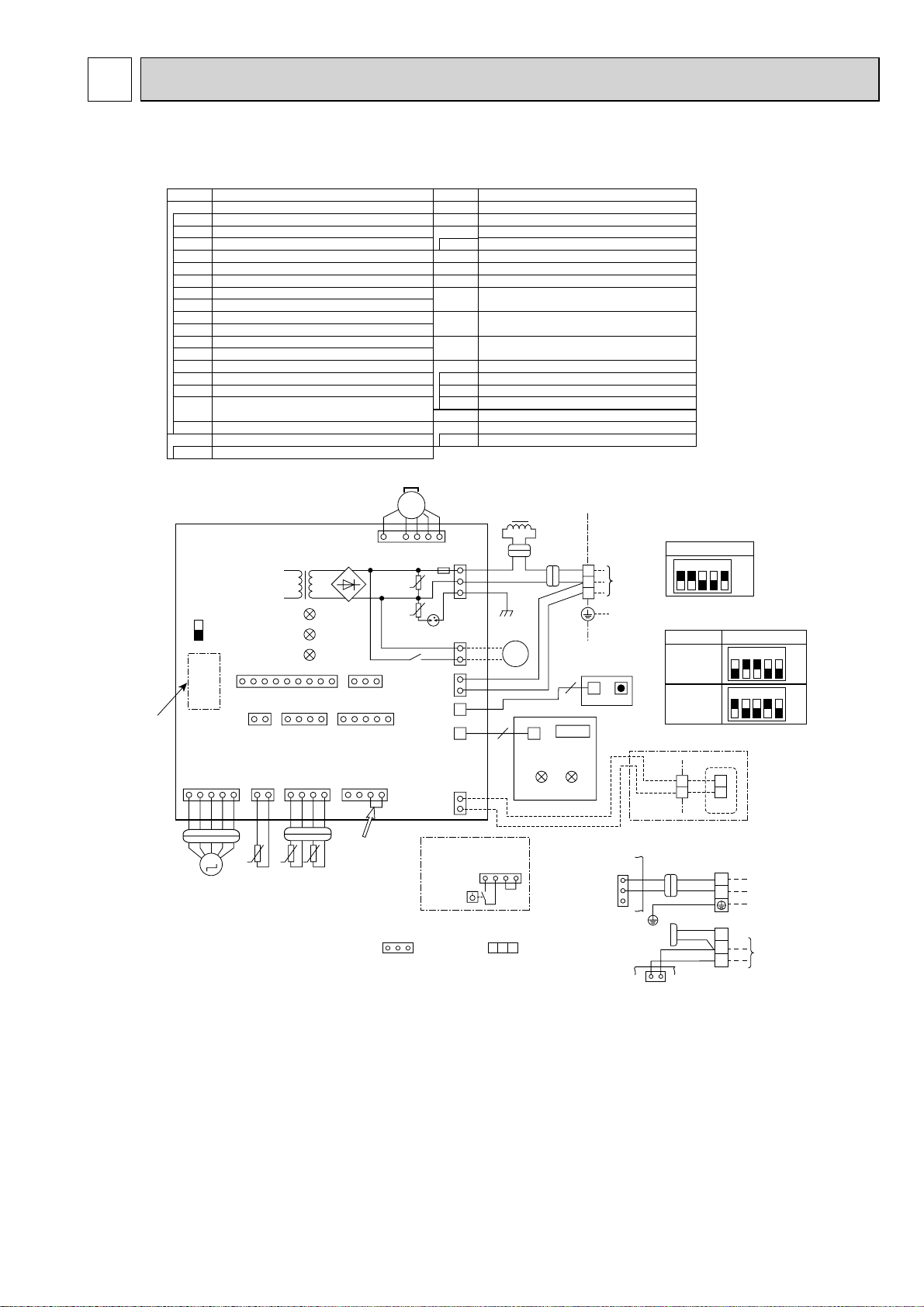
WIRING DIAGRAM
PKA-RP35HAL PKA-RP50HAL
[Explanation of symbols]
Symbol
I.B Indoor controller board
CN2L Connector (LOSSNAY)
CN32 Connector ( Remote switch)
CN41 Connector (HA terminal-A)
CN51 Connector (Centrally control)
CN90 Connector (Remote operation adapter)
DSA Surge absorber
FUSE FUSE(T3.15AL250V)
LED1 Power supply (I.B)
LED2 Power supply (R.B)
LED3 Transmission (Indoor-outdoor)
SW1 Switch (Model selection) +See table 1
SW2
Switch (Capacity code) +See table 2
Connector (Emergency operation)
SWE
X1 Relay (Drain pump (option))
ZNR01,02
Var ist or
Drain pump (option) power supply
CNP
(Drain pump (option))
CN4F Drain float switch (Drain pump (option))
R.B
Wired remote controller(option)
TB6
Terminal block (Remote controller transmission line)
I.B
SWE
ON
OFF
Refer to
tables
1and 2
CN151
(WHT)
11
M
Notes:
1. SymboIs used in wiring diagram above are, : Connector, : Terminal (block).
2. Indoor and outdoor connecting wires have poIarities, make sure to match terminal
numbers (S1, S2, S3) for correct wirings.
3. Since the outdoor side electric wiring may change, be sure to check the outdoor unit
electric wiring diagram for servicing.
4. This diagram shows the wiring of indoor and outdoor connecting wires. (specification of
230V), adopting superimposed system for power and signal.
+
1: When work to supply power separately for indoor and outdoor units apply, refer to Fig 1.
+
2: For power supply system of this unit, refer to the caution label located near this diagram.
Name
MS
CNMF
1
CN32
CN51
(WHT)
CN4F
(WHT)
ZNR01
ZNR02
X1
T11 DB1
LED1
LED3
LED2
CN90
(WHT)
11 1 5
2
CN2L
CN41
(RED)
(WHT)
CN20
CN44
(RED)
(WHT)
141425
○
t
t○t
TH1 TH2 TH5
1139
4
When attaching
drain pump(option),
○
remove the jumper
connector CN4F
and fit the drain
float switch (FS).
(WHT)
(WHT)
Symbol
M Vane motor
MS Fan motor
S.W
Switch board
SWE2 Emergency operation
TB2 Terminal block(Indoor unit Power (option))
TB4 Terminal block (Indoor/outdoor connecting line)
Terminal block (Remote controller transmission line(option))
TB5
TH1 Room temp. Thermistor
(0/15ΚΩ, 25/5.4ΚΩ Detect)
TH2
Pipe temp. Thermistor/liquid
(0/15ΚΩ, 25/5.4ΚΩ Detect)
TH5
Cond./eva. temp. Thermistor
(0/15ΚΩ, 25/5.4ΚΩ Detect)
W.B Pcb for wireless remote controller
LED1 LED (Operation indication : Green)
LED2 LED (Preparation for heating: Orange)
REC1 Receiving unit
DCL REACTOR
DRAIN PUMP (OPTION)
DP
DRAIN FLOAT SWITCH (OPTION)
FS
Name
3~
6
FUSE
U
CN01
(BLK)
U
DSA
3
1
CNP(BLU)
3
CN3C
(BLU)
1
LDSWE(A)
(BLU)
CNRU
(WHT)
1
CN22
(BLU)
2
When attaching drain
pump (option)
FLOAT SW
CN4F
(WHT)
DCL
1
3
5
YLW YLWYLW
ORN
BLK
DP
M
1~
ORN
BRN
W.B
6
LD101(B)
LED1
14
FS
ORN
2
RU
REC1
LED2
TB4
S1
S2
S3
S.W
LDSWE(B)
TO
OUTDOOR
UNIT
SWE2
+
1(Fig. 1)
CN01
(BLK)
1
3
5
I.B
CN3C(BLU)
<Table 1>
SW1
(MODEL SELECTION)
SETTING
12345
<Table 2>
SW2 (CAPACITY CODE)
MODELS
RP35
RP50
BLU
1
BLU
2
TB5
(OPTION PARTS)
I.B
YLW
ORN
GRN/YLW
INDOOR/OUTDOOR
3
1
COMMUNICATION
RED
BLU
YLW
ORN
ORN
BRN
R.B
TB6
TB2
TB4
S1
S2
S3
1
2
L
N
ON
OFF
SETTING
12345
12345
ON
OFF
ON
OFF
POWER SUPPLY
~(1PHASE)
230V 50Hz
TO OUTDOOR
UNIT
9

8
REFRIGERANT SYSTEM DIAGRAM
PKA-RP35HAL PKA-RP50HAL
Heat exchanger
Strainer (#50)
Refrigerant GAS pipe connection
(Flare)
Thermistor TH5
(Cond./ Eva.temperature)
Thermistor TH1
(Room temperature)
Thermistor TH2
Pipe temperature(Liquid)
Distributor
with strainer (#50/#50)
Refrigerant flow in cooling
Refrigerant flow in heating
Refrigerant LIQUID pipe connection
(Flare)
Strainer (#50)
10
 Loading...