

Page 1

MITSUBISHI
SWING
MACHINE
PARTS
CATALOG
1. *
1*
2. l:.fftil!.l
3.
4. l:.fdl,
5.
6.
7. Tfllt. 1:. T
8.
9.
10.
11.
m'i
~t....
~
~Udi~-§}-
*I
131Jn~·
¥f!
;;t
tl
7J
7 • «
t€i
~dl-
1J'
-
.Y.
1t
.lit
~
-§}-·
· · · · · · · · · · · · · · · · · · · · · · · · · ·······Arm
H$-§}-··
U
t11HM!!:6-§}-·
~
-1M$~
······· ···
lv
~-§}-·
..
···
················
• • · · • · .. · · · · · · · · · · · · · · ·······Needle
·····
·······················Upper
............................. Stitch regulator mechanism
$
-§}-·
· · · .... · ·
.. · ..
~
t)
fill$-§}-
........................ Rotating hook shaft
~
-§}-
.. · ... • ................. · ........
..
..........
fl6
£·
................................
~
·
· · · ........ · ........... · ........ Accessories
···
Model { PB-81
bed
and
·····Upper thread tension regulator mechanism ·
bar
shaft
· · · · .... · ···
..
··
..
Presser foot
Hook
mechanism · ...........
...... ····· ....... Qillubrication
Gauge
parts
0-1
PB-820-1
O(PB-81
O(PB-820)
0)
INDEX
its
accessories······· ·
and
take-up lever mechanism · · · · · · · · · · · · · · · · · · · · · · · · · · · · · · · · · · · · · · · · · · · · · · · · · VOI-5
and
vertical shaft
mechanism
mechanism · .............
...........................
......
and
feed l
· ... · · · .. ·
· · ·
.................
················································
·········
··
········
mechanism
................................
..........
· · · · .. ·
· · .. · · .. ·
ift
ing rock shaft
.....
· · .. ·
····
··········
.... · ......
· · ·
......
· .. · · · · · .... · · · · .. · · .... · · · · · · · .. · .. · .. · .. · .. ·VOI-15
........
....................... · ....
· .. ·
...........
······
··
..........
· · · · · · · ·
mechanism
· .. · ·
....
· .. ·
· · ·
....
·· ··
·····
·······
··················
······
......
· .. · · .. · · · .. · .. · · · · .. · · VOI-
........................
....
.. · .... · · ·
...
.....
. · · ..
.....
········
· ···
......
....
· ·
·· · ..... ..
· · .. · .. · · · ... · · · · ·
···
······· VOI-1
··· ··· ··· ·VOI-3
·····
......
........ VOI-21
····VOI-7
··VOI-9
· V
OI-1
· .. ·VOI-
··V
OI-23
11
3
19
.•...._
MITSUBISHI
ELECTRIC
CORPORATION
======================================================================197711======
Page 2

Ul
It
MODEL:
0
TOTAL
PB-81 0-I 0 ·
I
PB
-820-
ASSY.
820-I O(PB-81
I 0 I
I
0•820)
I
PB-8 I 0-
I 0 I j
--
-
--
----
~~
===============================PB8
10-10·820-10
===
Page 3

===================vol-1
PB
·810-
10·820-IO
(PB-810
·820
)m
*
ARM
f*
$ ~
BED
AND
ITS
ACCESSORIES
901
==========PB810
-
10·820-1o===
3 4 7 8
10
9
11
12 13
14
15
16
17
18
~~
-+----------22
25.
26
Page 4

P
B-81 0-1 0•820
"ft-1:"'-Ats~
Fig
.
No
. Part No.
M9
1
MF
3
MF
4
5
M9
M9 1107
6
7
MQ
M9
8
901
MF 20EO 550
9 M9
10
MF 40AO 1
11 MF
12 MF
13 MV
14
M9 1
15
M9 0901
16
M9
17 MF
MF
18
19
MF
20
MV
21
M9
22
M9
23
24
25
26
27
M9
28
MQ
29
M9 1110
- 1 O(PB-81
::J-j-'
1101
004
10AO
830
60AO
326
0915
003
002
50AO
584
1108
001 B
0503
065
81
20AO
476
10A1
555
01
AO
245
104
016
035
0908
015
10AO
186
60AO
880
10AO
180
01AO 181
0904
011
5001
062
1508
001
50AO 181
002
0•820)m
}lft;t::J-
Code Nc.
W466810
W321296
W452217
W502952
W500092
W453559
5038
46
W331471
W462774
W47026
W470268
W501636
W502479
W470267
W464008
W501371
W461744
W447193
B
409034
W456517
W500147
W461746
W450620
W110814
W462894
W462895
B
509088
W464979
W500294
l-""
9
$
~
*
A
RM BED
$
7 1
;t.
77
iiii
jJ
7
Jj'
11.
.;p.
~
1:::"
;....
~
-j--/
"f•J
7~-/ a ~{lA)
E
~
1~7~71
.A
""'
IJII
*-illil-T
a
i-:t
11.
·
:;
7
a #
*
tl
-
•:;
Ia
*-iJ"r
11.
.IDl
.y
*
tt
7-
.L..
~
~
!ill-t'-;,-
*-.iJ"r(7-.L..
.;p.
.Y 11/
~
-;,-
~
.Y 9/64(40) x 6 Screw (for Fig. 4)
*
'l
*
jJ
,,
.It:
.;1
.:t-
.Y 11/64(40)X 5.5 Set
.;1
'7
~
if
-T
.IDl
,,
.:t
~
;t.
-Y
.y
.:t-
'
.y
*
:lt
t•
7 ?
*
jJ
,.,. 3 hole thread retainer
(
7-.L..
*
1:"'
3
~
~
~
·:~
~
~
~
~
.Lt.
.;1
.:t-
T )
.:t·
~
AND
ITS
ACCESSORIES
<>
liD
11
(3)
·
n t
9/
9/
)
.Y 9/64(40)x
.,
~
.Y 15/64(28)x 7
.Y
11
~
64(40)
X 9 Screw (
Face
plate
Side
cove
/ 64(40) X 5.5
64(40ix 16
64(40)X
64(40)
/64(40) X 8 Screw (for Fig. 28)
14
X 7.2
6.5 Screw (for Fig. 20) 1 1
Screw (for Fig. 7)
Thread take-up
screw
Pre
-tension
E type stop ring 3
Thread guide 1
Spacer
Tension
Tension spring 1
Screw
Screw (for
Screw (for
Spool pin
Arm
side
Thread guide (arm) 1
Pin
(for
Name
Arm
and
Model plate 1
Model plate 1
Set
screw (for Fig. 902) 1 1
Thread guide (under arm) 1 1
{Ill/
Amt
Name
of
Part
for
Fig. 3) 3 3
r
cover
(for Fig. 19) 1
Assy,
discs
Fig.
18) 1
Fig.
18)
cover
Fig. 23) 4 4
Plate
bed 1
810 820
1
1 1
2
1
1 1
1
1
1
2
1
1 1
1 2
1 1
1
1
1 1
~
. req.
1
2
1
1
1
1
1
{I
Remarks
:Of
==================
vo
i-2
==========
PBB10
-
10·B20-1o
===
Page 5

===================voi-3==========PB810
-
10·B20-1o===
PB-81 0-1
0•820-1
O(PB-81
I
PB-81
0•820
0-
I 0 I
)m
J:.*UIMiiUIHt
UPPER THREAD TENSION REGULA TOR MECHANISM
I
PB-820-
I 0 I
-903
45 44 43
42
41
40
39 38 37 36 35
902
68 67
66
65 64 63 62
61
60
59
58
57 56 55
54
Page 6

P
B-81 0-I 0•820-
Fig.
'it
No. Part No.
902
35
36
37
38
39
40
41
42
43
44
45
90
46
47
48
49
50
51
52
53
54
55
56
57
58
61 MN
-t:~li!P:i.:J-
MV
M9
MF 10AO
MF
MV
MV
MF 10AO
MV
MV 01AO
M9 0212
MV 01AO
M9
MV
3
M9
M9
MN
MN
MN
MV 02AO
M9
M9
M9
MF 10AO
MN
MN 10AO
M9
59
M9
60
MN
62
MN 10AO
MN 10AO 851
63
64
MV
65
MN 10AO 554
66
MV 0
67
M9
68
M9 0919
01EO
1604
10AO
01AO
01AO
0 1
AO
0901 002
02EO 2
0902
0901
10AO
10A1
10A1
0902
0202
1003
10AO
0603
0203
10AO
10EO
02AO 221
2AO
0902
I 0
210
046
245
556
802
558
555
553
187
060
709
10
015
045
155
555
572
179
016
060
046
245
556
555
003
060
553
175
187
709
001
003
PB-8
t:
1 0 •
820
}ltt;f:J-j:
No
Code
W45769
W501027
W450071
B
419179
W458101
W458102
W444059
W458100
W458104
W4
627
87
W4581
W5007
W322775
W501026
W500307
W5022
W502212
W502065
W502211
W502210
W502064-1
W502940
W450071
W445934
W445933
W502062
W502064-2
W445932
03
41
13
W462825
W450012
W502148
W457582
W4500
W45758:!
W500187
W500930
11
~
1:.,'
UPPER
.
9
$
.
btdiUiiS
·:;
?
~
"T
* ~
-=J-/'\;t.
(*I)
..
,~
:fr-llll-=J-.DD.tt!':r:
f)
.1.1:.
liD
Jl
.on
Uj
-=J-
:Ill
-=f-
/(
I')
1IX
*
!="
/'.:t·.il:.J/7" '
Sf
...I::.~HIUliS
f~
"T
*
*
J:.
:fr-
*~!*!
~
1:t
!f-::l.Jf.,JI
Ul-=f-7
Ul
.liD.
t=
:J:t.
!f-::I.
IJII
*
!r-11ll
g,
*
*
n:;t.Jl:.J/7" •;! Y
~
T Y
:J:t.
;!
.:t
·
(*!)
i:t
!JL
*
".I
~
!*!
~
!*!
~!*l
..
-=f-/'*
7
:J:t.
Sf
.:t-
~
:.-(•1')
".1
r \
=f
:;t
'it
-=J.:t-
Sf
J
f.,JI~/(•1
-=J-
~
l*l
/\.
f)
y
/\
::1.
)f.,
Jl
IJII
-=J-
.t.i:.
Jl ;t. Y 9/64(40)X4.5
!JL
*
R
RE
THRE
~
*
~
.on
~
*
/ 2¢X
y
.:l.
y
y 9/
~
..Lo.
a
.liD.
AD TEN
D
""
1/
4(40
64(40)
9/
64{40)
35
SION
-1S
) Thread tension regulating thumb
><6
GULATOR
Thread
tens
Thread tension
Thread tension
Tension regulator stop plate
Tension regulator bracket 1
Tension disc 2
Thread tension stud
Thread takeThread tension releasing pin 1
Thread tension regulator bushing
Set
screw
(for
Thread tension regulator Assy, 1
Tension releasing spring set screw 2
Nut
Thread guide bracket
Thread gui
Thread
tensiCin
? Controller cover
Y 9/
64(40)x 18
~
.:t-
I
.liD.
Y
3/32(56)X
')
2¢X15
...
*
.:t·
.:t·
~
..
.:>.
Y 9/ 64(40) x
12
14
Thread tension
Tens
ion
releasing
Thread
Thread tension spri
Tension regulator
Tension disc 4
Thread controller disc screw
Tension
Tension stud
Thread controller d
Thread take·up spring
Tension relea
Tension rel
Tension stud 1
Tension spring stop bushing 1
5
tens
releasing
Screw
Screw
MECHANISM
Na
me
of
Part
ion regulator Assy,
nut
!J:!I'i~
releasing
up
spring 1
Fi'g.
de
disc 2
spring 2
releasil}g_
ion regulating thumb
sin
g spri
easi
ng plate
disc 1
41)
screw 2
pin (small)
nut
ng
presser
disc
pin (small)
isc
ng
Amt
810
1
1
1
1
1
1
1
1!1115
. req.
820
~
Remarks
2
2
2
1
3
2
2
1
1
2
2
1
1
1
1
1
====================
voi-4
==========:
PB810-10
·
820-1o
===
Page 7

===================voJ
-
s==========PB810-10·820
-
1o===
PB-81 0-1
0·820-1
75
76
77
78
79
80
81
82
83
84
85
86
O(PB-81
0•820)m
91
iN$, 7Crf
NEEDLE
92
93
94 95
A-$~
BAR AND
96
TAKE-UP
LEVER
MECHANISM
88
89
90
109
109 108
107 106 105 104 103 102
Page 8

-
PB
8 10 10
-
-
Fig.
No. Part
75
MF 60AO
76
MF
77
M9
78
MF 60AO
79
MF
80
MN
81
MN
82
MF
83
M9
84
MV
MV
85
86
MF 10AO
MF
87
88
M9
MF
89
90
91
M9 1516
92
MN
MP
93
MV
94
MN 10AO
95
96
MN 10AO
97
MQ
98
M9
99
M9
100
101
102
104
103
105
106
1
07
1
08
109
110
MF 60A2
M9
MF
MO
MV
M9
M9
MF 10AO
MF
M9
M9
.
820
IO(
PB
-
No
.
742
10A2
740
1102
001
663
10E2
148
10A1
500
10A1
740
10AO
665
0909
003
01AO
660
02AO
660
664
10A1 181
0802
003
10A2
181
001
10AO
587
0080
582
02AO
582
588
387
50AO 661
1601 001
1513
001 B
740
1606
001 8
20AO
352
50AO
232
01AO
383
1802
006
1801 002
662
10AO
326
1110
002
1606 001 8 504
8 10
-
Code No.
W502181
W500003H01
W500489
W461760H01
W469534H01
W502071
W500801
W450054H01
W50
W45480
W454842
W450055
W502073
W502074
W502075
W499814
W500006
W445883H0
W462789
W462903
W445881H01
W445886H0
W322778H01
W500486H01
509060
W501524
504016
W470214
W453556H01
W453555H02
B
503851
W500306
W444056
W443934H01
W500294
.
820)m
H01
1901
8
016H01
3t._
~
7
7 X
~"T.YJ.I:.;l;t-y
ittf;l
7
-t!
7 X
it
:A.
&t
it
ittf;l
:)'f-;fJ.;-(if~;l
:A.
-!f-:t.J.;-
~rfA..$~
'
NEEDL
$
)1,..
1-
(jftf;i
~
)1,..
7 7
•
:;p.
*
~
)1,..
:;p.
E BAR
&!.
~
~
J!,..J:.)
11
(..I:.)
1::
1:
2.5¢X
:--
)I,..
1-
6c6X 32
~
:f
Y
9/64(40)
...
~
(T)
~
J!,.."'f)
Y 1 /8(44)x 4.5
*
(iN')
/ 64(40)
it
~"T.YJ.I:.;l;t-y
:Xt::--:;tz
1
:X
1
I::
:X
:X
~7"
I::
I::
:--
?7:--?t:::-it-?7:--?tl•;l
.Y
J.l:..,.,..
~
7" .Y
J.l:.
;I
7 X
:Ji
jJ
..1::..$
? 7
,tf$t:iJL
)I,..
7" .Y
J.l:..,.,..
7 - Upper shaft collar
......
~
)1,..
:;p.
*
jf
&t
?
)'i'j
:;p.
.:t-
~"T.YJ.I:.;l;t-y
15
!64(
U
:--
:--
I)
iit
I-'
:t·
Y
1/4(40)x3
;t-
Y 15
1-
:t·
Y 1
/4(40)x
(~)
:--
? Crank
Y
9/32(28)X
*
y
9/32(28)x 13
1
1-'
~
y
11
1/4(40)x6
AND
TAKE-UP
~
x2.
200
x 6
28) x
;64(28)X
6
/64(40)
15
11
16
X 8
--
LEVER
Needle
Needle
7
Set
screw
Needle bar bushing (upper) 1 1
Oil wick
Plastic plug (for F
Felt
Needle bar connecting stud
Screw
Needle
Needle
Need
Thread guide
Needle
Thread guide
Set screw (for Fig. 92) 1
Take-up lever support stud
Take-up lever
Take-up lever 1
Take-up slide block
Crank pin
Needle
Set
screw (for Fig. 104) 1 1
Set
screw
Fe
lt
Set
Upper shaft bushing (left)
Set
Set
Needle bar connecti
Square
Sc
rew (
Screw (for
MECHANISM
Name
of
Part
bar upper bushing
bar upper
(for Fig. 82) 1
bar
bar
le bar bushing (under) 1
clamp screw 1
bar
screw (for Fig. 102)
screw (for Fig. 104)
screw (for Fig. 104) 1
block (for Fig. 82) 1
for
bush
(for Fig. 78)
ig.
connecting crank rod
(for Fig. 103)
Fig. 107)
Fig. 1 04)
cap
ing
cap
felt
84. 85) 1 1
--
ng
link guide 1 1
0
Amt.
810
1
1
2
2 2
1
1
1
1
1
1
1
1
1 1
1
1
3 3
2 2
2 2
1
1
1 1
1 1
2 2
1 1
1:>
req.
820
2
--
fil
Remarks
1
1
1
1
1
1
1
2
1
1
1
1
1
1
1
1
2t
============
===
====
vol-s==========
PBB10
-1
0·B20-1o
===
Page 9

====================voi-7=========='PB810-10·B20-1o===
PB-81
0-1
0·820-1
O(PB-81
0·820)m
q.
r
.l:.
fl,
Hfi
&Hr
UPPER
SHAFT
~m
AND VERTI
CAL
SHAFT
MECHANISM
126
127
904
128
\\\\I
129 130
131
132
100
134
133
135
136
131
37
37
138
139
140
115
141
142
905
Page 10
PB
Fig.
No. Part
115
116
117
118
119
120
121
122
123
124
125
126
904
127
128
129
130
131
132
133
134
135 MF
136
906
137
138
139
140
141
-
810
I 0
-
iJ"-t::7-e6fA::J-t:
M9
MV
MF
MF
MO
MF
MQ
MF
M9
MF
MF
MV
MV
M9
MF
MF
M9
MF
M9
M9
M\f
M9
MG
MV
M9
142
M9
.
820 I O(PB
-
No
.
1606
001
01AO 331
10AO
333
60A3
740
70AO 521
6780
522
70AO
520
10AO
352
1508
001
10AO
334
10AO
332
01AO
230
01EO
280
1508
001
60A1
740
60A0
700
1516
001
60AO
233
1502
002
6580
682
2201
003
01EO
384
1203
002
3080
740
01AO
744
1803
036
1802
045
. z
810
82C)m
-
)lttf::J-t'
Code No.
B
504016
W444106
W444107
W500956
W462791
W462734
W452369
B
422B44HJ1
B
509088
W444109
W444111
W322709
W462790
W452225
B
509088
B
409336
W500738
W500836
W500006
W451575
W500509
W322737
W461726
B
509178
W464014
W322035
W322024
B
508959
B
508961
J::.fi
~fi$-9-
..
•
UPPER
Jl-Tvl.l:.....-;f::;
***
7
***
!UIII_,..?
Rta....-?JL-
H
jJ
iiJirvl.l:.....-;;t.::;
$l!Bllt
$tlllt
..1::.
~
IJ
~
llJi
-;-
.J.,.
jJ
7 X
r\
5'1
7"
J:.fi..>l?
lJl
/'
:11.
~'5:..-~c·:~
lJl
7 X
~
7 :..-?
7
7-/o\-l!JI;f:.-Y
-;-
$
X
jJ
1)
.,;..-
.,;..-
:X
lJl
'"
'5
.J.,.
l.l:.
7.
l.l:.
'"
*
*
9-
•)I
SHAFT
(J:.ti)
(RJ:.)
'"
(..1::.)
(T)
(§!T)
(Tfa)
(*11.)
jJ
.....
::t-
""
Jj...
_,..
::t-:::;
(:6)
'
*
t:(M)
Jj...
1:1
•)I
Q
CID
1
1-
••
15
..
A
:::;
15/64(28)x8
1)
1-
*
15/64(28)x
Y
15/64(28)X
•
:::;
11
:::;
3/16(28)X
1-
...
X.
9/32(28)x23
1-
AND
-1!.
4(40)x6
/64(28)x8
/32(28lx
VERTICAL
15
12
1 o Screw (for Fig. 135)
15 Screw (for
SHAFT
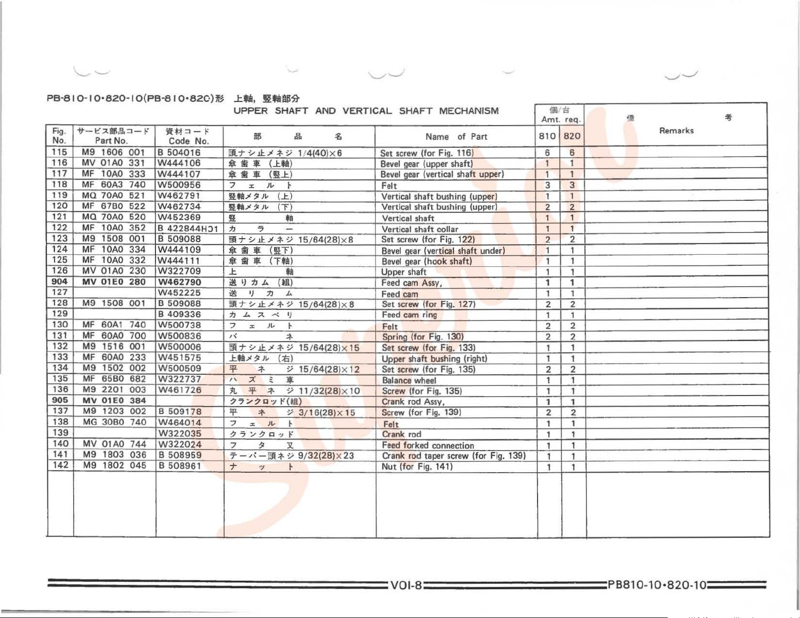
Set
screw
Bevel
gear
Bevel
gear
Felt
Vertical shaft bushing (upper) 1
Vertical shaft bushing (upper)
Vertical shaft
Vertical shaft collar
Set
screw
Bevel
gear
Bevel
gear
Upper shaft
Feed
cam
Feed
cam
Set
screw (for Fig. 127)
Feed
cam ring
Felt
Spring (for Fig. 130)
Set screw (for Fig. 133)
Upper shaft bushing (right)
Set
screw
Balance
Crank rod
Fe
lt
Crank rod
Feed
forked connection
Crank rod taper screw (for Fig. 139)
Nu
t (for Fig. 141)
MECHANISM
Name
(for Fig. 116) 6 6
(upper shaft) 1
(vertical shaft upper)
(for Fig. 122)
(vertical shaft under)
(hook shaft) 1
Assy, 1 1
(for
Fig. 135) 2 2
wheel
Assv.
Fig.
fill iS
Amt. req.
of
Part
139) 2 2
810 820
1
3 3
2 2
1
1
2 2
1 1
1 1
1 1
2 2
1 1
2
2 2
1
1 1
1
1 1
1 1
1 1
1
1
1 1
1 1
II,
Remarks
1
1
1
1
1
1
2
1
1
1
1
~
===========
===
=====
voJ-s
==========
PBB10-10·B2o-
1o
===
Page 11

===================vot-s=========:PB810-10·820
-
1o===
PB-81 0-1
0·
820-1
O(PB-8 I 0•
820)
m @ §
STITCH
1JIIiltU'UJUli!~
REGULATOR MECHANISM
156
157
1
175
174
173
172
171
170 169 168 166 168
906
167 165
Page 12
.
-
-
PB
810
I 0
820 I O(PB
Fig.
-if-
1::' .A
No. Part No.
150
151
152
153
154
155
156
157
158
159
160
161
162
163
164
165
166
167
168
169
906
170
171
172
173
174
175
il6J:.
M9
1802
M9
0801
M9
0905
MF 10AO
M9
1807
M9
1504
MV
01AO
M9
1513
MF 10AO
M9
0902
MF 10A2
MV
01AO
MF 10AO
MF
11
DO
M9
1209
M9
1207
M9
1003
MF
10AO
1501
M9
MF 60AO
MF
10EO
MF 60AO
M9
1501
MF
60AO
M9
1110
MV
01AO
MV
01AO
.
- -
:J - t
045 B 508961
051
063
153
015
002
152
001
750
063
572
640
852
631
002
003
653 B 503895
632
002
633
635
634
007
572
002
708
738
8 10
:itM:J-1-"
Code
W461797
W501377
W447215
W501406
B
508963
W452298
B
509060
W502090
W456514
B
509164
W452299
B
419163
W331486
B
503887
B
509288
W453509
W502945
W462608
W462614
W447217H01
B
509256
W445312
W500294
W445315
W452226
820)ffl
No
.
HC1
H01
liU~:fJD~a'l.ffUa~
~
STITCH
7
tt
#
:;p:
~
~ T :J
~
f:t
:;p:
pg
~
RJi
T
:/
•;.t
7
~
1:t
jljl
:/
*
~
~
1
:;p:
:;p:
1t
r\
*
til
13
!fi-
13
1i
QI31Jil;,ll@
13
1:1
• * 1t
)I,.
';I
!fi-
r\
;t-
~I
$
·-;
1::::"
:;p:
*
.lC
::;
IJ
*
1Jp
*
1JpJafa
1Jilil!tB!e
~
*
.lC
"'
REGULATOR
0
'"'
9 32(28)
1-
-Bi
/
'/
j-
:¥
::;
:t-
::;
:J
.;/.:f.:/
.::L
/
1::::"
:t-
·~
"'
)I,.
~
::;
::;
-Bi
1llZ
-¥
::;
(*.ll)
:t·
::;
/\
:t-
::;
"'
*&
B8S
9¢>
9/32(28)><23.3
15/64(28)
15/64(28)X
9<t>X44
3!16(28)
3!16(28)x6
15/64128lx8.5
15/64(28)x 14.5
11 /64(40l
~
T
:/
/\
.lC
*
~
;,a
!fi-
..
:g
'<.
27
X 1 0
x 8
x 8 Screw
MECHANI
10
.5 Screw
SM
Name
of
Part
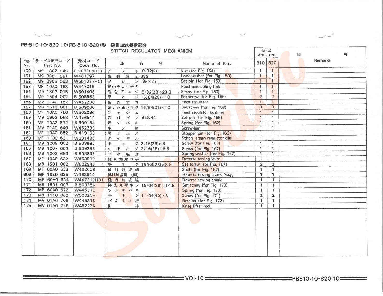
Nut
(for Fig. 154) 1
Lock washer
Set pin
Feed
Screw
Set
screw
Feed
Set screw
Feed
Set pin
Spring
Screw-bar
Stopper pin
Stitch length regulator dial
Screw
Spring washer
Reverse
Set screw
Shaft
Reverse
Reverse
Set screw (for Fig. 170) 1
Spring {for Fig. 170) 1
Bracket
Knee
(for
Fig. 150) 1 1
(for
Fig. 153) 1 1
connecting
(for
regulator 1 1
regulator bushing
(for
(for
(for
(for
sewing lever 1
{for
sewing crank Assy,
sewing crank 1 1
(for
{for
lifter
link
Fig. 153) 1
(for
Fig. 156) 2 2
(for
Fig. 158) 3
Fig. 156)
Fig. 162)
(for
Fig. 163)
Fig. 163)
Fig. 167)
(for
Fig. 167) 1 1
(for
Fig. 167)
Fig. 167)
Fig. 174)
Fig. 172)
rod
810 820
I
I
im
i;
Amt. req.
1
1 1
1
3
1
1
I
1 1
1 1
1 1
1 1
1 1
1
1
I
1 1
1
2
2
1 1
1
1
1
1
2
2
1 1
1 1
ca
Remarks
I
~
-
===================vot
-
1o==========PB810-10·820-1o==:=
Page 13
==================vol-11
=========:PB810-10·820-1o===
PB-81 0-1
0•820-1
907
908
O(PB-81
184
182
180
181
0•820)m
lif1
it
ft.IH1t
$ ~
PRESSER FOOT MECHAN,
185
186 187
188
189 185
JSM
190
191
192 193
194
195
205 204 203
202
201
200
199
197
_ _)
198 197
196
Page 14

-
PB
8 10
Fig.
No. Part No.
907
908
180
181
182
184
185
186
187
188
189
190
191
192
193
194
195
196
197
198
199
200
201
202
203
204
205
.
10
820
-
-tt-~~e
MV
OlEO
MV
02EO
MV
OlEO
MV
02EO
MV
01AO
M9
3201
M9
1508
MF 20AO
MV
01AO
MV
01AO
M9
0505
MF
60AO
M9
1551
M9
1505
MF 40AO 591
M9
1251
MV
01AO
MF
60AO
M9
1104
MF 60AO
MF
10A2
MV
01AO
M9
1102
MF
10AO
M9
1102
MF
60AO
M9
0704
IO(PB
-
.e.:J
-r
974
974
973
973
262
035
001
265
259
510
063
725
016
016
045
593
729
003
594
245
220
033
267
001
252
063
.
810
820)~
-
)fft;i:J-~
Code No.
W456513
W326206
W456530
W457577
W456526
B
409037
B
509088
W467222
W461782
W472525
W464038
B
309199
B
503843
B
509176
W462748
B 50917'7
W452219
W444040
B
509264
B
419209
B
409092
W472529
W502123
W502081
W500489
W443698
B
503977
¥II-
~l!HJI$
A. R
PRESSER
$
c
c
r:l
r:l
flit
flit
liJi
flit
flit
'/
~~
1::-lfl:.JTT:J
~
~
7
T "I
7
1::
11.
7
fil
*
i!p::c~f.J19Jv
~-T.YJ.l:..JI:fY.
~
~;cJ:.JT~~
~
::c
-r
;c
.,
l:.JT
ft
it
:J
*
:J
7
7
7
7
~
.Y
;c
11.
11.
:J
!Jl
~~
it
.::1.
~
;c
~.xtt(*A)
flp.x.(lll)
~;c{*.(l)
fllt;c<f!l)
;c
J.l:.
...
-+t
~~
IJ
ill
;t-
Jl
:lf
r\
1
~
!Jl
.::t-
!Jl ;t.
1l
~
/{
*
~
{±
/'
'"'
.:t-
..1:.
~
FOOT
a
""
...
-Y
1/2{28)x 43
;t-
-Y
15/64{28)x
:f
;t.
9
~
:;;
15/64{24)x
-/
15
"¥
..
~-
*
-Y
11/64(40)x
!ti-
*
.;1
-Y
1 1 /
11/64(40)x2
11
MECHANISM
~
/ 64{28)X
3/16(32)
64(40)X
7¢X19
Roller
Roller
Roller
Roller
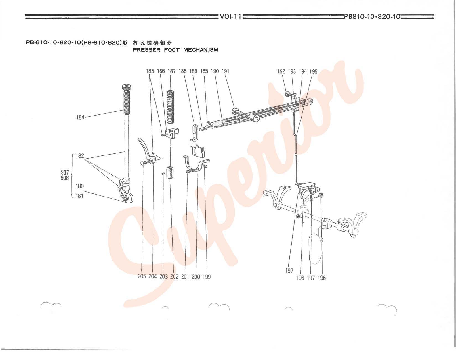
Presser
Presser
7
30
10
12
23.5
Set screw {for Fig. 182. 183) 3 3
Presser
Presser
Knee
Knee
Knee I ifter
Knee
Screw (for Fig. 193)
Knee
Nut
Knee
Spring (for i=ig. 198) 1 1
Screw
Knee
spring (for Fig. 200)
Tension releasing lever
Set screw (for Fig. 200)
Presser
.7 Set screw
Presser
Presser
Amt
Name
of
Part
presser
bar Assy,
presser
bar Assy,
presser
Assy, 1
presser
Assy,
bar Assy,
releasing
bar holder 1 1
spring 1 1
lifter
lifter lever
lifter
lifter
(for
lifter
(for
lifter
bar bushing
bar
bar
thumb screw 1 1
lever
link
pin 1 1
lever.
lifting
lever hinge screw
lever
joint
Fi~.
195)
lever connection rod
Fig. 198) 2 2
lever connecting rod finger
(for
Fig. 202)
lifter
lifter
pin
810
1
1
1 1
1 1
1 1
1 1
1 1
1 1
1 1
1 1
1 1
1 1
1 1
I
1
1 1
1
1 1
{lilt;
. req .
820
1
1
1
1
,.
3J
Remarks
===================
vo
i-12
==========
PB810-
1
0·820-1o
===
Page 15

P8-810-10·820-IO(PB-810·820)m
210
211
212 213 214
""Ffi,
l:.""F*'HIIfl!Ht
ROTATING HOOK
215
216
SHAFT
217 218
AN.D
219 220
FEED
221
LIFTING ROCK
SHAFT
MECHANISM
228 220 224
239
238
229
230
237 236
909
224
235
234
233 232
231
230 229
Page 16

PB
810
I 0
820 I O(PB
- - -
-
Fig.
~-t::~$.r..:::J-t-'
No. Part No.
210
211
212
213 MV
214
215
216
217
218
MF 10AO
M9
M9
0606
01AO
MV
01AO 281
M9
0901
MF
M9
MF
219 MF
220
MF
221
M9
222 MF 1
223
M9
224
M9
225
M9
226
M9
227
MF 10AO
228
M9
229
M9
230
M9
MV
231
232
MV
233
234
235
909
236
237
MQ
MF 10AO
MQ
MF
M9
MG
238
M9
239 MF
3001
10A2
1110
10AO
6680 491
60A3
1503 001
OAO
0402
1113
1108
0901
1513
2403
2402
01AO
01AO
70AO
70AO
60EO
1113
3080
1112
6780
81
0•820)
ROTATING
~tf:::J-1-'
Code
286
W454875
052
W502467
050
W502480
278
W462893
W452246
002
W500741
352
W501442
002
W500294
283
W501447
W454811
740
W500956
8
508971
279
W447172
050
W461040
002
W500182
001
8
503846
060
W501107HG1
287
W446173
001
8
509060
034
W464015
045
8
509118
452
W462738
460
W320450
450
W454833
352 8 422844
452
W462736
276
W462749
002
W500182
W462642
276
002
W501889
451
W462735
No
"'Fti
J:."'F~
'
HOOK
~.I)
1£
fiB
ffj.)f?JL-
.
m
~l)!i
~
!jL
j]
~
~
IJ
~3txfill
*
!j1.
7 X
~"T.Y.J.I:.)f;t.y
~l)!i
ll£
.;p.
~
7 .Y
I:'/
(~IJII!e.lft)
~I)
......
~7.Y.1.1:.)f;t.y
-i!/?
7
Tfa..>l?
J:.
T
T
j]
Ttil..>l?
]!
IJ
Ji(J:.Tti:}(fll}
!j1.
~IJ!i
.!fL
Tfi..>l?JL-
lJ
SHAFT
~
~
(]j(~ti:)
.L>..
I)
c:l
Y
.:t·
7
y
*
u
~I)
,.,
~
(]j(~:fi)
~
Y
.:t·
.1.1:
..>l
.t•
Y
?,.,
.:t·
Y 3/
..
)
~
Jt-
(:Ei)
~
IJ
ta
'*
7
( tta) Rotating hook shaft bushing (middle)
Jt-
Y
.:t·
(J:.Tti:)
y 1 1 /64{40)
*
(11:)
-
tiS~
AND
FEED
..
""
15¢
6
.3¢
9/64140l
11
/64(40)
15/64(28)X4.5
4.5¢
11164140lx
11
/64(40)
9.5¢x25
15/64(28)x10
8(28)x35
3/ 8(28)
11 /64(40)X 15 Screw (for Fig. 237) 1 1
~
x4
X 8
X 5 5
)(
LIFTING
15
12
ROCK
Feed
Slide
Washer
Feed
Feed
Set
screw (for Fig. 216)
Collar (for
Set screw (for
Feed
Feed
Felt
Set screw (for Fig. 234) 2 2
Feed
Washer
Screw (for Fig. 222)
Set screw (for
Feed
Set screw (for Fig. 227) 1 1
Screw (for. Fig. 232) 2 2
Set pin (for
Nut
(for Fig. 229)
Rotating hook shaft bushing (right)
Feed
Rotating hook shaft 1
Collar (for Fig. 233)
Feed
Feed
Screw (for Fig. 213)
Rotating hook shaft
SHAFT
Name
rock shaft bushing (left) 1
washer
(for
(for
Fig.
rock shaft crank (left)
bar 1
Fig.
bar shaft
rock shaft 1 1
rock shaft crank (right) 1 1
(for
Fig.
rock shaft bushing (rig
feed
lifting
rock shaft
lifting
rock shaft
lifting
rock s
MECHANISM
of
Part
Fig.
213) 1 1
214) 1 1
214) 1 1
Fig.
218)
224)
Fig.
226) 1 1
ht)
rock crank rod) 2 2
cra
nk
(left) Assy, 1 1
haft
crank (left) 1 1
bush
ing (left)
{lit
Amt. rep.
810 820
1
2 2
2 2
1 1
3 3
2 2
5
1 1
2
1 1
1
1 1
1
2 2
1
I
ill
Remarks
1
1
1
5
2
1
1
1
1
25
==================
vol-14
==========
PB810-10
·
820
-
1o
===
Page 17

===================:vol-1s==========PB810
-
10·820
-
1o====
PB-81 0-1
0·820-1
O(PB-81 0·820)m
249 252
254 258 259
1J
7
:tit«~
HOOK MECHANISM
71-
271
270 269
268
267
266 265 264 263
261
260
Page 18

PB-81 0·1
Fig.
No
. Part No. Code No.
245
246
247
248
249
250
251
252
253
254
255
256
257
258
259
260
261
263
264
265
266
267
268
269
270
271
0·820·1
-ft-t:~II6.!1:J-I'
M9
1110
MV
01AO
M9
1107
MV
01AO
MV
02JO
MV
01AO
MQ
70AO
MV
02AO
MV
01AO 101
MV
02J2
M9
0911
M9
1261
MQ
70AO
MV
02A1 339
MV
02AO
M9
0801
M9
2051
M9
1102
MV
01AO
M9
1103
M9
0502
M9
1252
M9
11 12
MV
01AO
MQ
70AO
M9
1112
O(PB-81
002
339
002
104
104
429
603
603
101
011
045
339
339
053
003
011
325
045
053
016
015
272
563
002
)!t~:J-1'
W500294
W452253
W500092
W456512
W457581
W502315
W220170
W220610
W456511
W457580
W502316
B
W462792
W462826
W458129
W462800
W502313
W500197
W502314
W501528
W500301
W502325
W501531
W452248
W322036
W501889
0 •
820)ffl
509177
:fJ7
!l·$~
HOOK MECHANISM
.Y
-
.Y
I)
I)
~
~
ti
ti
.Y
~
Ol)
(J:.il)
("F)
if
.Y 5/ 16{24)x
*
.Y
=t·
"-1
~
a!
it'
=t-
.Y
* .Y
~
......
Cl
.y
a
Ql>
11/64{40)x8
11/64(40)x5.5
(1/16)
{1
/ 16) Needle plate
9/64{40)x7
3/16{32)
M8
11/64{40)x7
1 1/64(40)
M5
3/16(32)x 13
11/6~40)
11/64(40)x
$
.!p-
=t-
/{
tJ
il
.!p-
*
~
~
.X
:t
~l)~llll#~
~I)~
11ll1t
it
~t
.DJl
11.
T
f:J/{-~
f:l/-\-~
f:l/-\
/'
11.
11.
11
T 7
/{
f&
f&
~
ill
.!p-
#
it
~
*
.!p-
.DJl
*
11.
·~
.lF-
.lF-
I)
11
=t-
*
m
{I/~
Amt
. req.
Name
of
~
Screw (for Fig. 246) 4
Rear
cover plate 1
Screw
{for
Fig. 248. 249)
Feed
dog 1
Feed
dog
(1
.
.5
26
x
15
12
Supporter plate
Feed
plate set bracket 1
Feed
plate
Needle
Screw (for Fig. 253. 254) 2
Nut
Cover plate 1
Cover plate 1
Cover plate (lower) 1
Spring
Sc
rew
Screw
Squa
re block
Nut
Spring washer
.3
Screw 1 1
Screw 1
Fe
ed plate
Side cover plate bracket 1
Screw (for Fig. 270) 4
1 6) 1
set
plate 1
(1
washer
(for
Fig.
Part
bracket
'16)
2501
810 820
1
1
1
1
1
1
2
1 1
6 8
6 6
2
2
1 1
1
1
1
1
1
1 1
ill
Remarks
~
===================
vo
i-16
==========
PBB10-10·B20-
1o,===
Page 19

===================voi-17==========PB810
-
10·820-1o===
PB-8 I 0-I 0·820-1
O(PB-81
0·820)~
1J
HOOK MECHANISM
"?
t1l
m $
~
910
92
296
294
r.---..
304
300
302
301
303
299 298 295 293
297
Page 20

PB
-81 0-1
Fig.
o.
N
280
910 MV 01AO 120
281
282
283
284
285
286
287 MV
288
289
290
291
292
293
294
295
296
297
298
299
300
301
302
303
304
0•820-
if-~~~!t::J-r
Part No.
MV
01AO
MF 10AO
M9
0904
MQ
70AO
MG
2300
01
AO
MV 01
MV 01AO
M9
M9 1
M9
M9
M9
MV
MV
MV
MQ
M9
MQ
M9
MQ
MQ
M9
0912
0903
AO
809
1113
0920
01A1
02A2
02AO
70AO
1651 001
70AO
1109
70AO 341
70A1
1606
1 O(PB-8
356
123
010
470
740
356
303
300
015
002
003
010
003
339
339
339
352
330
001
330
001
1
0•820
)!ft;t
::1-
Code No.
W462892
W
4663
W462794
W457400
W445964
W602318
W456529
W502203
W220171
W502320
W452252
W502319
W500713
W501866
W500697
W500463
W452249
W458128
W458129
W502332
W500996
W462801
W500985
W452295
W452223
B
504016
Hf~
r
86
1J
7MUUB~
HO
OK MECHANI
tlll
?
1J
1J
1J
?
it
~
*
;t- Y
1lll
~
"'
7
.:J::
?
1J
;t
7-r
;t
7 1-
f&:
1:t
:!jl ;t-
:!jl
;t-
:!jl
n
1lll
.::t·
:!jl
n
j)r:
t&
11/'
t&
jJ/'
t&
1J?fa1J7
!ill 1- y
J.1:.
$
ti
~-r
Y
J.l:.
1J
? • ;tl 9
$
li
~T
Y
J.l:.
SM
Name
of
.H.
..
(U) Hook
? Hook
~
~
9/64(40)x27
IJ
t&
}I.-
1-
.....
..
"'
......
"'
y
9/32(28)x9
y
9/64{40)X
Y 1 1
.::t·
Y
9/64(40)x6
Y
*
;ti
;tL
;ti;:t. Y
9/64(40)x8.5
(it:J) Cover plate 1
(J:.foJ)
(T)
.::t·
y 1/
•
(n·Ui)
;t- Y
11/64(40)x6.6
Jl.-
*
(Tfi~)
1/4(40)X7
.f.
/64(40)x4
4{24)X4.8
8.5
Hook shaft
Assy,
Noodle bracket
Bobbin
Screw (for Fig. 280)
Slide plate 1
felt
Hook shaft supporter 1 2
Rotating hook opener brack
Rotating hook
Screw (for
Screw (for Fig. 289)
Screw
Screw
Screw (for
Cover plate 1
Cover plate 1
Hook shaft collar
Set screw (for
Bevel
Set
Hook shaft bushing
Hook shaft
Set screw (for
fig.
(fo~
fig.
Fig.
gear
screw
(for Fig. 302) 1 2
bevel
Part
et
opener
289) 1 2
295 297) 8
295-297)
fig.
298)
gear
(lower)
Fig.
303) 4 8
111/
i:t
Amt. req.
820
810
1 2
1
1 2
1 2
1 2
1 2
1 2
1
1 2
2
1 2
16
1 2
2
1 2
1
1 2
{I
Remarks
2
2
2
4
4
2
-:lt
===================
vol-1s
==========
PBB10
-
10·B20-1o
===
Page 21

====================voi-19==========PB810
PB-81
0-1
0 •
820-1
O(PB-81
0·820
)m la
OIL
~diM«
ill~
LUBRICATION MECHANISM
911
319
-1
320
321
I ;, I
322
~
i~
-
10·820
-
1o===
323
332
331
I
330 329
912
t=
.......__.____,\T---+----
326
325
-----
324
327
Page 22

PBSIO
- -
F1g.
No. Part No.
308
309
310
311
312
313
314
315
911
316
318
319
320
321
322
323
324
325
326
327
912
329
330
331
332
.
10
820
-ft-t'A$§.:::1-('
M9
0502
M9
1102
10E1
MF
1104
M9
MF 10AO
10E2
MF
60A5
MF
60AO
MF
MF
60EO
M9
1851
M9
0603
M9
0906
MF 60AO
60A4
MF
MF 60AO
MF
10E2
MQ
70AO 731
MF 60A1
M9
11
M9
1503
MQ
60EO
M9
1851
M9
1503
M9
1113
MQ
70AO
IO(PBSIO
-
053
045
148
002
689
148
740
133
711
002
060
011 B
134
740
139
148
689
tO
002
002
712
002
002
002
710
.
-
820)ffl
~tt:::J-1-'
Code
W500301H01
W501097H01
W464047
B
509264H01
W444230H01
W464023
W500906
W445617
W464017
W462784H01
W447199H01
509269H01
W445619H01
W500905
W447200
W462984
W464046
W444233H01
W500294
B
504000H01
W464035G01
W462784H0t
B
5040001-0t
W500182
W322736
No
~
.
.
Jg'~ti!HJU~~
OIL
LUBRICATION
$
/"<\
;t.
''J
-T
.=£
jt
-¥
r\1
7-t-
;m
1::
7 X
i
lb~:..-7
11
* a
.;:p.
*
~
jt
liil
7
7 X
;m~:..-7
1::
ilb
t:--
)1,."'17
"'17-t-
.;:p.
*
-¥
*
••
ft("f}(lll)
.;:p.
*
-¥
.;:p.
*
*
..
·-
QQ
"'
:&:
IIi
;t.
Jv~-
Jv
CJ:.>
,;t.
Jv
Jv~-
M5
~
11
/64(401
*
1.5~X710
.Y
11
/64(40lx
;:
2.5~x35
"'
(~)
em>
.Y
9/32(20)X16
/
.Y
9/64(40)X7
~
~
(;b)
;:
2.5¢X
.y
1 1
/64(40)
.y
15/ 64(28)x 5 Screw 1
.Y
9/32(20)x
.Y 15/ 64(28)x 5 Screw 1 1
.Y t t
;64(
iii
(tr
Hi)
-
MECHANISM
~
Spring washer
Nut
Woolen yarn
12
150
X 8 Screw (for F
t 6
40)
x t 5 Screw (for Fig. 332)
Screw (for Fig. 312)
Pipe
Oil wick 1 1
Felt
Oil
cap
Gear
Screw (for
Gear
Screw
Cover plate 1 1
Felt
Oil tank (right) 1 1
Oil wick
Oil_llipe (vinyl) 1 1
Pipe
Gear
Screw
Gear
Name
holder
(left)
box (upper
gear
box (upper) pin 1 1
(for Fig. 320)
holder 1 1
box (lower set) 1 1
box (lower) 1 1
ig.
of
set)
box)
325)
Part
ill/
Amt. req
810
1
1
1
1 1
1 1
I
1
1 1
1 1
1
2 2
1 1
2 2
1
1 1
2 2
~
820
1
1
1
1
1
11
Remarks
1
1
:if
==================
vol-2o
==========
PBS10-10·820-1o
===
Page 23

====================vol-21
==========:PBB10-10·B20-1o===
PB-820-I O(PB-820)m
~
19
..
:
,\
~
-7-:/~1}
GAUGE
.
PARTS
600-604
606-607
609-612
616
~
-~
-~
617-619
620-622
~
~
605
608
613
614
~
615
Page 24

PB-820-
Fig.
No. Part No.
600
601
602
603
604
605
606
607
608
609
610
611
612
613
614
615
616
617
618
619
620
621
622
I 0
PB-820
-tt-l:";;!.llfScr..:J-1-'
MV
02JO
MV
02J1
MV
02J2
MV
02J3
MV
02J4
MV
02JB
MV
02JO
MV
02J4
MV
02J8
MV
02JO
MV
02J2
MV
02J3
MV
02J4
MV
02J8
MV
02JO
MV
02J8
MV
02AO
MV
02JO
MV
02J3
MV
02J4
M9
6601
M9
6602
M9
6603
101
101
101
101
tOt
t 01
104
104
104
102
102
102
102
102
105
105
103
103
103
103
052
052
052
m
)
-7-::;$~
GAUGE PARTS
W~:J-1-'
Code No.
W458123
W458162
W45758C
W464994
W464998
W457595
W457581
W465200
W45759E
W458124
W45757E
W46499S
W46520
W457597
W457577
PL-22-26-9
W457587
W457578
W464997
W464999
W465205
W465206
W465207
-T-.Y-+t-1'
~
;t&
;t&
~
~
;t&
1)
1)
I)
~
~
~
~
~
I
I
(ittr)
(il)
(fl)
(
fl)
~
1t O.St
1t
..
""
0.
1.2t
~
it
it
it
it
it
it
~
~
~
it
~
~
it
it
it
it
111'
¥II
it
it
it
it
A
A
A
~
~
~
;t
~
~
~
~
~
P'l
P'l
J.i
Be
1£
1
6t
.t;
Name
of
Part
Needle
plate 1
Needle plate
Needle
plate 1
Needle
plate 1
Needle plate 1
Needle
plate
Feed
dog t 1 1 1
Feed
dog
Feed
dog
Needle clamp 1
Needle clamp 1
Needle
clamp
Needle clamp t
Needle clamp 1
Presser
foot
Presser
foot
Needle guide
Needle
guide
Needle guide 1
Needle guide 1
Washer
Washer
Washer
!
I
1 1.2
1 t
t t t
1 t
t 1
~Gauge
3
64 1 16 3 32
1.6
1
1
t
1
1
1 8 1 4
2.4 3.2
1
t
t t
1
1 1
Size
6.4
IQ
Remarks
1
1
1
2t
===================
voi-22
==========PB
810-10
·
82
0-1o===
Page 25

====================vot
-
23==========PB810
-
10·82
0-
1o===
PB-810-10•820
-
IO(PB-810•820
•
801
)~
it Jjt
ACCESSORIES
~
~809
~ ~808
w
.
810
.,
811
r
812
818
i
~
819
~
~806
~807
805
813
®
~814
~815
Page 26

PB-81
0-1
0·820
F1g.
it-l::."~
No
. Part No.
800
801 MF 60AO
802
803
804
805
806
807
808
809
810
811
812
813
814
815
816
817
818
819
820
821
l$.!'L:J-
MF 60AO
MN
10AO 561
M9
0501
MF 60AO 137
MB 02A1
MB 02AO
M9
1601
MN 10AO
MV 01
M9
0570
M9
0401 041
M9
0608
MN
10AO
MF 20EO
MV
OlEO
M9
0501
MF 60AO
MQ
70AO 131
60AO
MF
- 1 O(P
B-81
0•820)m
(:
JU;1
Code
749
P
833000X01
419
W449461
W445508
040
W990016
83100
P
DPx5#16
608 P 842002XC1
P
842003X01
W466240
W445507
W5027
W502078
W990010
W462776
W990002
W445964
SM31097
SM31037
4.5x
W220627
W322757
W319408
AO
608
003
060
778
080
050
123
190
727
040
734
608
:::1-
No
1X01 ;
40
25
..
# a
ACCESSORIES
f
.
ft
Vi
•
liD.
dl
a
Ui
j£
*
$
.y
it
:t-
~
@I
.y
:t·
~
@I
.y
.;p.
11.
•
':I
"'
:::~·
~
.t..
11.
*
lSi
n
~
*
*
*
1::
it
J:.
;r
it
7
* *
~
--
j
l,..jJ
;Iii
:t·
~
@I
.y
AA
a
'"'
a
RA
il
::i
.t..
• (2) Hi
~
*
*
*
5.
(
:7;:)
( ')
')
( cp)
~
1/4(24) X9 Screw 4 4
jl:
( 1)
ftjl
z
ti
~
4.5x
M6
~
(8~)
~
5x25
20
:..-
f±
Ul-
f± m
~
/{-
~
{
:7;:
)
illl/
~
Amt
. req.
Name
of
Part
Access
ory box 1 1
Vibration preventi
nge
(2) 2 2
Screw
Oiler
(large)
Needle 4 6
Screw
driver (small)
driver (middle)
Screw
Hinge (1) 2 2
Bed
presser
Rubber plug 1 1
Screw 2 2
Washer
Nail 8 8
Bobbin
Bobbin winder
Knee
lifter
Screw 1
Vinyl
cover
Oil
reservo
ir
Screw driver (large) 1 1
ng
rubbers 4 4
810
4 4
1 1
1 1
1
1 1
2
4
1 1
1 1
1
1 1
820
il
Remarks
1
2
6
1
1
~
==================voi
-
24==========PB
81
0-
10
·820-
1o===
Page 27

 Loading...