

Page 1
English
Installation and Setting Manual
For safe and correct use, please read this manual thoroughly before operating the PAR-WT40R-E and PARWR41R-E devices.
FOR INSTALLER
Deutsch
Français
Nederlands
Español
Italiano
Português
Dansk
Svenska
Norsk
Suomi
Installations- og indstillingsvejledning
Læs venligst denne vejledning grundigt inden betjening af enhederne PAR-WT40R-E og PAR-WR41R-E af
hensyn til sikker og korrekt brug.
TIL INSTALLATØR
Installations- und Konfigurationsanleitung
Lesen Sie sich zur sicheren und korrekten Verwendung diese Anleitung bitte sorgfältig durch, bevor Sie die
Geräte PAR-WT40R-E und PAR-WR41R-E verwenden.
FÜR DEN INSTALLATEUR
Manuel d'installation et de configuration
Pour garantir une utilisation sûre et appropriée, lisez attentivement le présent mode d'emploi avant d'utiliser
les dispositifs PAR-WT40R-E et PAR-WR41R-E.
POUR LES INSTALLATEURS
Handleiding voor installeren en instellen
Voor een veilig en juist gebruik moet u deze handleiding goed doorlezen alvorens de PAR-WT40R-E en PARWR41R-E apparaten in gebruik te nemen.
VOOR DE INSTALLATEUR
Manual de Instalação e Definição
Para uma utilização segura e correcta, é favor ler cuidadosamente este manual antes de trabalhar com os
dispositivos PAR-WT40R-E e PAR-WR41R-E.
PARA O INSTALADOR
Manual de instalación y configuración
Para un uso correcto y seguro de los dispositivos PAR-WT40R-E y PAR-WR41R-E, lea este manual antes de
su utilización.
PARA EL INSTALADOR
Manuale di installazione e impostazione
Per un uso corretto e sicuro, leggere attentamente il presente manuale prima di utilizzare i dispositivi PARWT40R-E e PAR-WR41R-E.
PER L'ADDETTO ALL'INSTALLAZIONE
Installations- och Inställningsmanual
För säker och korrekt användning, var god läs denna manual noggrant innan du använder PAR-WT40R-Eoch PAR-WR41R-E-enheterna.
FÖR INSTALLATÖREN
Installasjons- og konfigurasjonsanvisning
Les denne bruksanvisningen nøye før du bruker PAR-WT40R-E og PAR-WR41R-E, for å sikre trygg og riktig
bruk.
FOR INSTALLATØREN
Asennus- ja asetusopas
Turvallisen ja asianmukaisen käytön varmistamiseksi lue tämä käyttöopas huolellisesti ennen PAR-WT40R-Eja PAR-WR41R-E-laitteiden käyttöä.
ASENTAJALLE
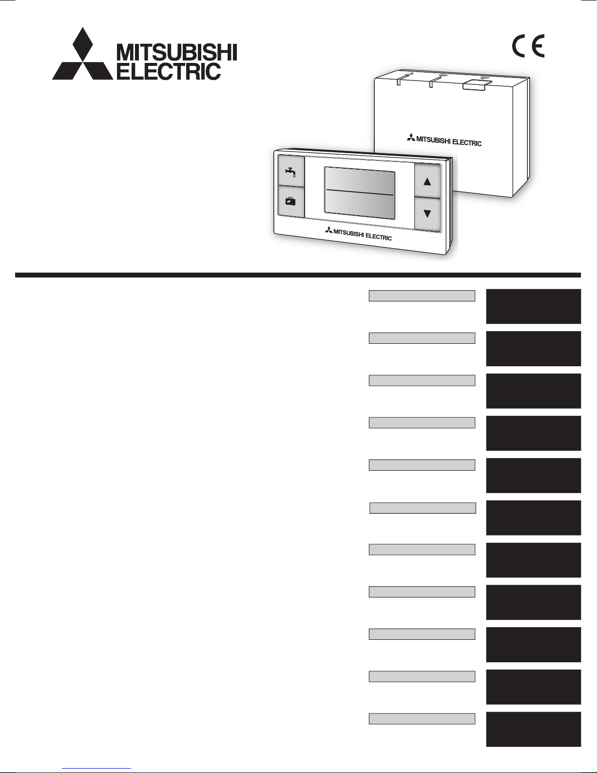
ATW WIRELESS SYSTEM
PAR-WT40R-E
PAR-WR41R-E
Page 2
1. Safety Precautions ...............................1
2. Accessories and Installation Tool .........3
3. Before using ATW wireless system ......3
4. Installing the Wireless Receiver ...........4
4.1 Connecting to the Cylinder unit ........4
4.2 Connecting to the Hydrobox unit ......8
5.
Setting the Wireless Remote Controllers
..10
5.1.Viewing the Address Number .........11
5.2.Pairing ............................................12
5.3.Switching the Temperature Unit ....14
Contents
5.4.Communication Test ......................14
5.5.Displaying or Hiding the Room
Temperature ..................................15
6. Wireless Receiver Operation ..............16
6.1.
Functions of Buttons and Displays
..16
6.2.Turning on Power ...........................17
6.3.Wireless Receiver Functions ..........17
7. Q&A ....................................................18
8. Specications .....................................19
1
Warning
►Installation
Do not use the device in particular environments.
Do not use the device in particular environments
where the following substances are present in
large amounts: oil, vapour, organic solvent, corrosive gas (such as ammonia, sulphuric compounds,
and acid or the like), or where acid or alkali solution, or particular sprays are used frequently. This
could affect operating performance, or cause
corrosion, which could result in electrical shock,
breakdown, smoke generation, or re.
Do not place the devices in an environ-
ment where ammable gas may occur,
stay, ow in, or leak.
Build-up of flammable gas could result in fire or
explosion.
1. Safety Precautions
● The precautions mentioned below are important to use the device safely. Be sure to understand and follow them.
●
The following hazardous classification shows the likelihood and severity of hazards if a person does not follow the instructions contained on the following signs.
Warning
Indicates a hazardous situation which, if a person does not follow the instructions, could result in death or serious injury.
Caution
Indicates a potentially hazardous situation that, if a person does not follow the
instructions, may result in bodily injury or property damage.
This manual explains installation of the PAR-WR41R-E wireless receiver and the
PAR-WT40R-E wireless remote controller, and settings of these devices. Before installing the devices, read this manual thoroughly. After reading, be sure to hand this
manual to the user.
Page 3
2
Caution
Do not drop the device. This could break the case or affect the device enough
to make it inoperable.
Install the device in a place capable of bearing its own weight .
If the device is not installed securely or properly, the
wireless receiver may fall.
Disposal
This symbol mark is for EU countries only.
This symbol mark is according to the directive 2002/96/EC Article 10 Information for users and Annex IV, and/or to the directive 2006/66/EC Article 20 Information for end-users
and Annex II.
Your MITSUBISHI ELECTRIC product is designed and manufactured with high quality materials and components which can be recycled and/or reused. This symbol means that electrical
and electronic equipment, batteries and accumulators, at their end-of-life, should be disposed
of separately from your household waste. If a chemical symbol is printed beneath the symbol,
this chemical symbol means that the battery or accumulator contains a heavy metal at a certain concentration.
This will be indicated as follows: Hg: mercury (0.0005%), Cd; cadmium (0.002 %), Pb: lead (0.004%)
In the European Union there are separate collection systems for used electrical and electronic products,
batteries and accumulators.
Please, dispose of this equipment, batteries and accumulators correctly at your local community waste collection/recycling centre.
Please, help us to conserve the environment we live in!
Warning
The device must be installed by a
dealer or an authorised technician according to the appropriate installation
manual.
If the device is installed improperly, electric shock
or re could result.
Do not place the device in an environment that exposes it to large amounts
of vapor or condensation.
Electric shock, re, or breakdown could result.
►Wiring
The wireless receiver’s maximum voltage is 12V DC. Do not connect 230V
AC power source to the wireless receiver.
Breakdown, ignition, or re could result.
Connections must be made securely
and without tension or external force
on the terminals.
If connections are made improperly, breaking of
wire, heat generation, or re could result.
►Others
Do not use sharp objects to press the
buttons.
Electric shock or breakdown may result.
Do not touch or operate the device with
wet hands.
Electric shock or breakdown may result.
Do not wash the device with water or
solution or the like.
Electric shock or breakdown may result.
When installing or repairing the device,
ask a dealer or a qualied technician.
If the device is not installed properly, electric
shock, smoke generation, or re could result from
entry of dust or water.
Do not disassemble or modify.
Page 4
3
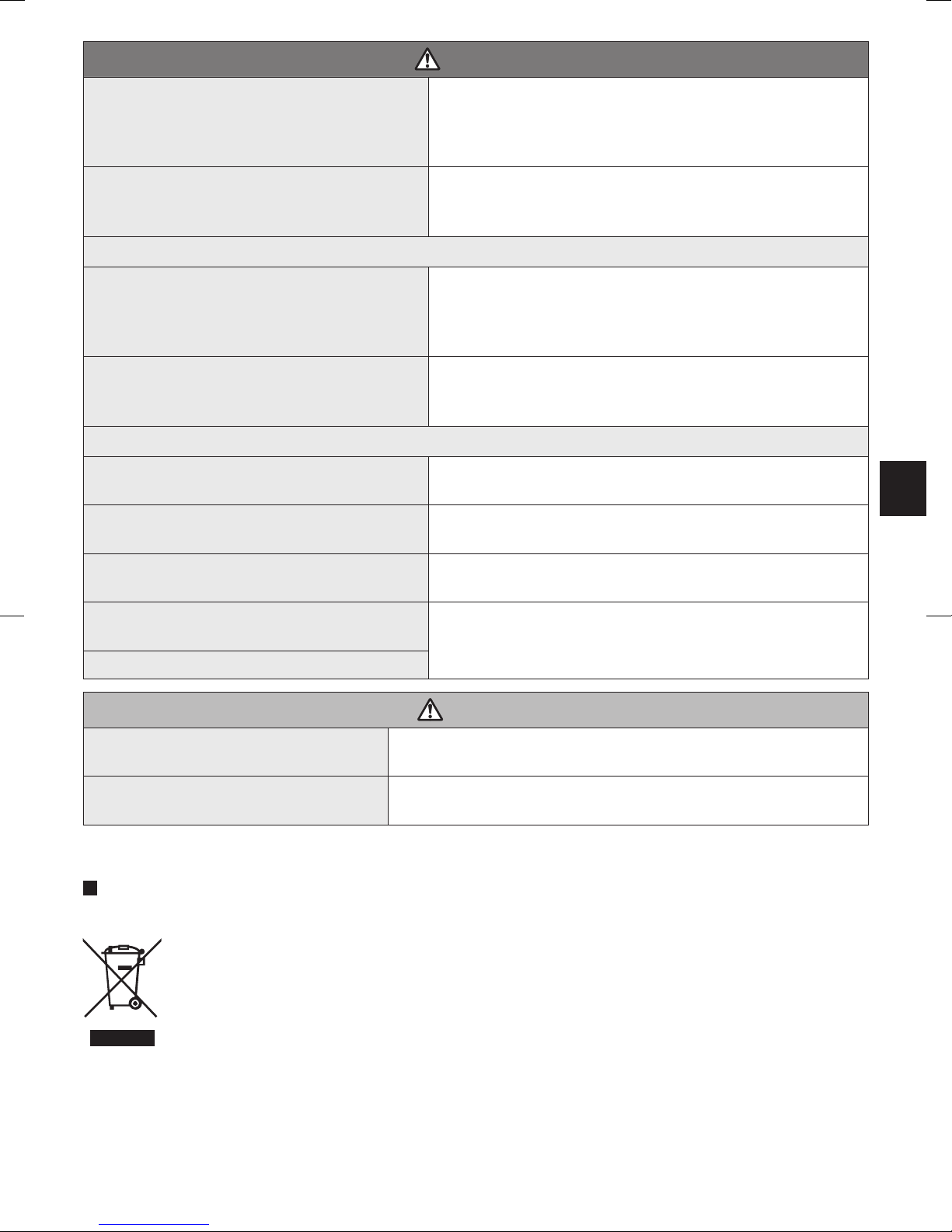
2. Accessories and Installation Tool
The following items are included in the box.
Item Nos.
Wireless receiver <PAR-WR41R-E>
(2 m long cable included)
1
Bracket 1
Flat head screw (4.1 × 6) 4
Installation and setting manual 1
* Installing of the devices requires a Phillips-head screwdriver (No.2 6 mm).
3. Before using ATW wireless system
Following is the summary of the procedure for installing and setting the wireless system.
1. Devices and manuals required to set and install the wireless system
PAR-WR40R-E wireless remote controller
PAR-WR41R-E wireless receiver
ATW wireless system installation and setting manual (this manual)
Wireless remote controller operation manual
(hereinafter abbreviated as OM)
ATW system installation manual
(hereinafter abbreviated as IM)
2. Installing and setting procedure
Power off the ATW system.
Install the wireless receiver on the ATW system.
(See "4. Installing the Wireless Receiver" in
this manual
.)
When installing the wireless receiver, be sure to set the SW1-8 on the control
board to ON. (See “5.1 DIP Switch Functions” in IM. )
Power on the ATW system, and the LEDs will blink on the receiver for 3 seconds.
Place two size AA alkaline batteries in the wireless remote controller.
(See “·Battery” in “4. Before Operation” in OM.)
Perform pairing process between the wireless receiver and the remote controller.
(See “5.2. Pairing” in "5. Setting the Wireless Remote Controllers” in
this manual
.)
The wireless receiver goes through a pairing process only while the ATW system
is off. When the system is ON, be sure to turn it off before beginning the pairing
process.
Page 5
4
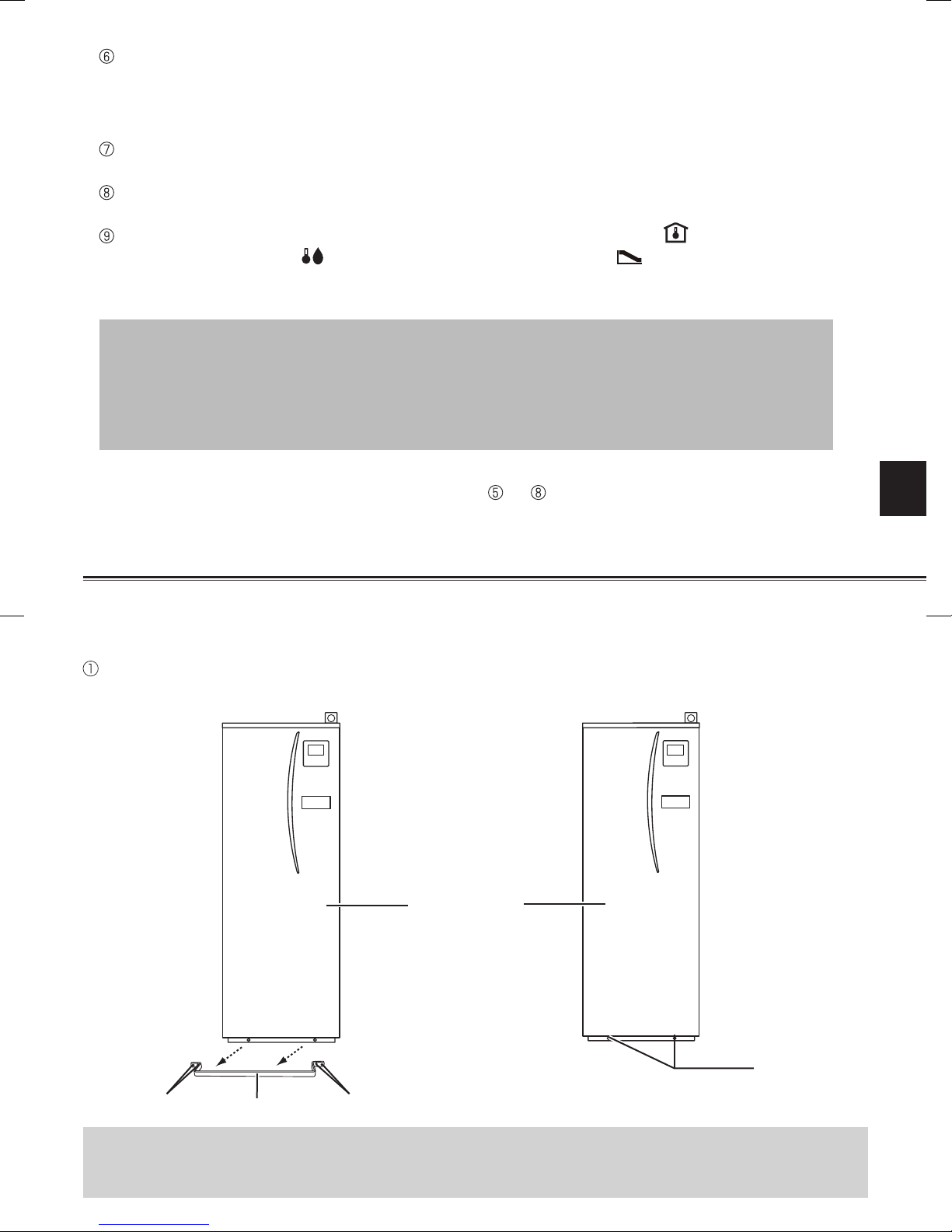
4. Installing the Wireless Receiver
4.1 Connecting to the Cylinder unit
* Before installation, be sure to turn off the main power supply.
Remove the handle by removing four screws.
Remove the two screws that hold the front panel, and remove the panel.
Screws
(2 positions)
Front panel
If the removed front panel is set aside away from the indoor unit, ensure the relay
connector on the main controller is disconnected.
Handle
Test wireless communication between the wireless remote controller and the wireless
receiver.
(See “5.4 Communication Test” in “5. Setting the Wireless Remote Controllers” in
this
manual
.)
Position the wireless remote controller in an appropriate place.
(See "4. Before Operation" in OM.)
To set the wireless remote controller as a room sensor that monitors room temperature,
see "5.4 Main Controller Initial Settings" in IM.
Use the main controller to set the ATW system to the room temp. ( ) mode.
When the ow temp. ( ) mode or the compensation curve ( ) mode is selected, the
wireless remote controller will operate as a thermostat. (See “■ Initial Settings” of “5.4 Main
Controller” in IM.)
When the remote controller set as a room sensor runs out of battery or gets a
communication error during room temp. mode, the room temp. mode will automatically switch to the compensation curve mode.
The room temp. mode will be restored by battery replacement or solution of com-
munication error.
Installation and setting of the wireless remote controller is complete. To set additional
wireless remote controllers, repeat from Step to .
Screws (4 positions)Screws
Page 6
5
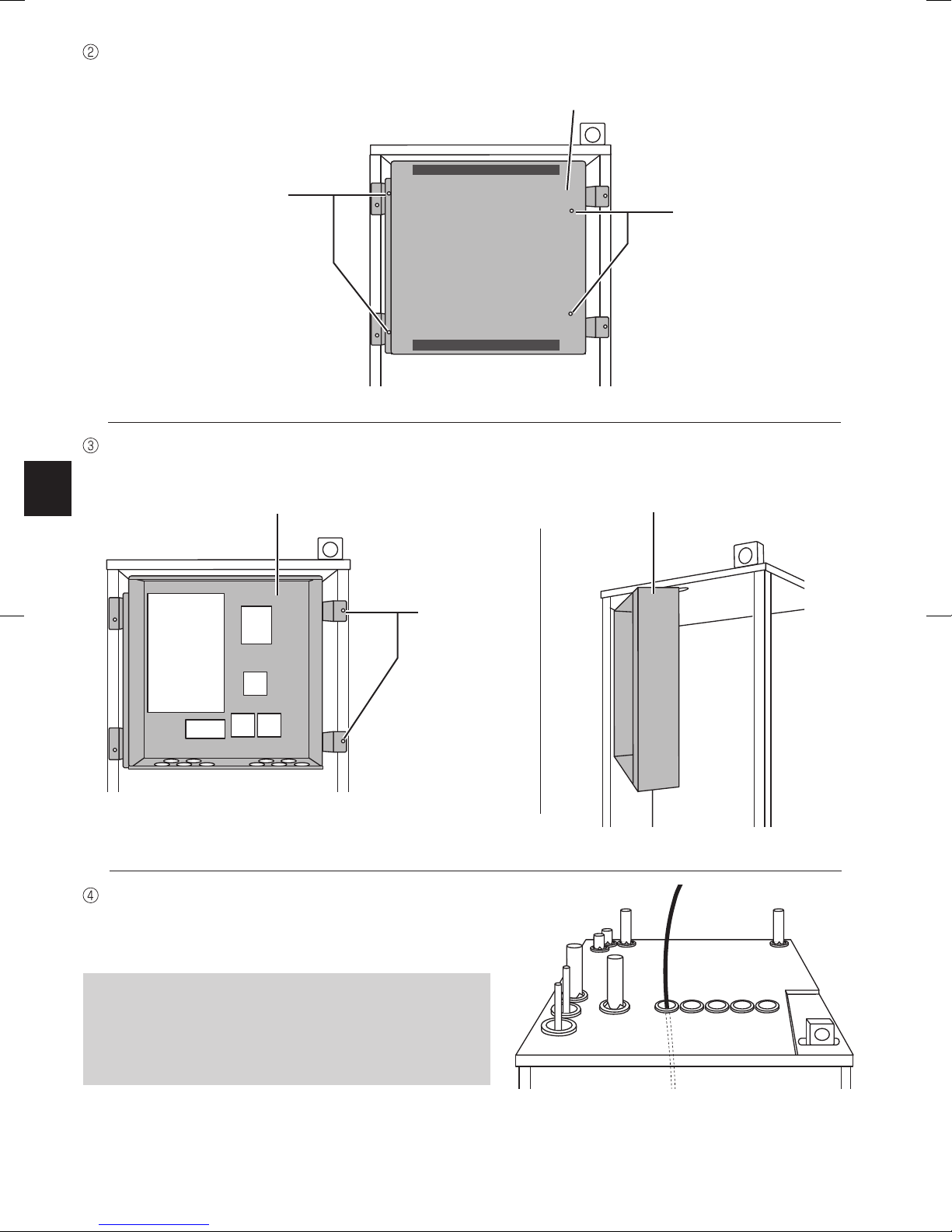
Remove the four screws to remove the electrical box cover.
Electrical box cover
Screws
(2 positions)
Screws
(2 positions)
Run the receiver's cable into the cylinder unit
through the left-most opening on top of the
unit.
Remove the two screws to pull the electrical box so that the electrical box is swung toward
you from right.
Electrical box
Electrical box
Screws
(2 positions)
Do not run the receiver's cable through an
opening that a power cable goes through
and do not bundle the cable together with a
power cable.
Page 7
6
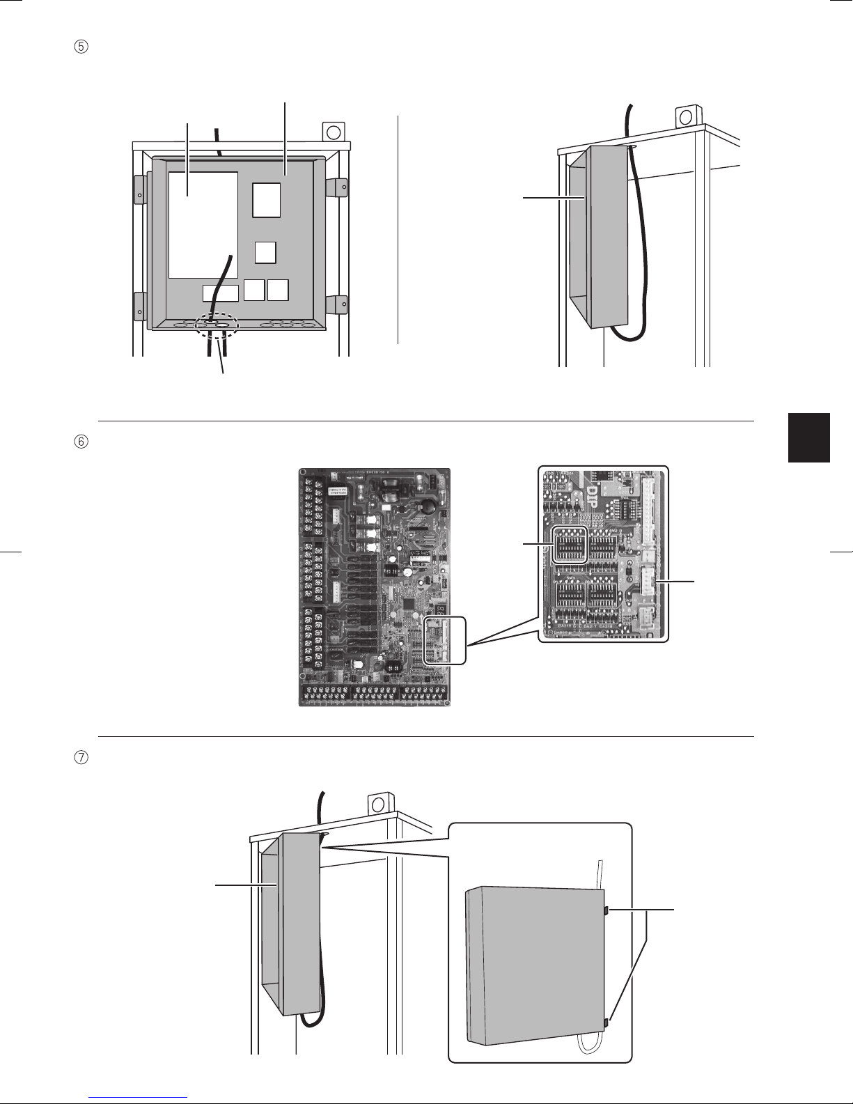
Route the cable out the back of the electrical box, and run the cable into the box through any
of the shown openings on the underside of the box.
Electrical box
Electrical box
Control board
Connect the cable connector to the CNRF terminal on the control board. Switch ON SW1-8.
CNRF
Remove excessive slack on the cable and secure the cable with two cable fasteners on the
side of the electrical box.
Electrical box
Back of electrical box
Cable
fasteners
Any of these 2 openings
SW1
Page 8

7
Check the maximum reach of the cable and
install the bracket on the wall with screws.
Place the electrical box back in the original position and reinstall the two screws.
<Notice>
● Do not overtighten the screws.
►The bracket may deform or break.
● When installing the bracket, select an interference-free space.
►Keep the installing area at least 10 cm away from metal or a wall box. If unable to do
so, always place the room wireless remote controllers in locations where the communication test determines that the wireless remote controllers are fully capable of
communication with the wireless receiver.
● Do not install the bracket with screws on the exterior casing of the cylinder unit.
►The internal parts may be damaged, which could result in breakdown of the indoor
unit.
Place the wireless receiver on the fixed brack-
et.
Hook the holes on the back of the wireless receiver onto the projections on the bracket, and
fix the wireless receiver in place.
<Notice>
● Do not place the wireless receiver inside the cylinder unit.
►Both the wireless receiver and the indoor unit may break down, produce heat, and
the wires may break.
● Do not let the wireless receiver stand on top of the cylinder unit. Always x the
wireless receiver onto the bracket.
►Wireless communication performance may be affected.
● Do not pull the cable excessively.
►Breakdown, ignition, or fire may result.
● Do not leave the wireless receiver suspended.
►Breakdown, ignition, or fire may result.
Close the electrical box cover, and fix it with screws.
Fix the front panel and the handle with screws.
Do not excessively pull the cable when
checking the maximum reach.
If the relay connector on the main controller has been removed, connect the relay
connector again before reinstalling the front panel.
Page 9

8
Electrical box
Control board
4.2 Connecting to the Hydrobox unit
* Before installation, be sure to turn off the
main power supply.
Remove the two screws that hold the front
panel, and remove the panel.
Screws
(2 positions)
Front panel
Remove the four screws to remove the electrical box cover.
Electrical box cover
Screws
(2 positions)
Screws
(2 positions)
Route the receiver's cable into the hy-
drobox unit through the opening on the
underside of the unit. Then route into
the electrical box through any of the
shown openings on the underside of
the box.
Do not bundle the receiver's cable
together with a power cable or run
the cable through an opening that a
power cable goes through.
Any of these 2 openings
Page 10

9
Connect the cable connector to the CNRF terminal on the control board. Switch ON SW1-8.
CNRF
Check the maximum reach of the cable to
install the bracket with screws.
<Notice>
● Do not overtighten the screws.
►The bracket may deform or break.
● When installing the bracket, select an interference-free space.
►Keep the installing area at least 10 cm away from metal or a wall box. If unable to do
so, always place the wireless remote controllers in locations where the communication
test determines that the wireless remote controllers are fully capable of communication with the wireless receiver.
● Do not install the bracket with screws on the exterior casing of the hydrobox unit.
►The internal parts may become damaged, which could result in breakdown of the in-
door unit.
When installing the wireless receiver,
observe the following.
● Keep the other electric or electronic
devices (e.g. radio, induction cooker, microwave, and refrigerator, mobile phone
or the like) at least 50 cm away from the
wireless receiver.
● As much as possible, place the wireless
receiver in an interference-free area and
keep the wireless receiver away from
metal.
Do not excessively pull the cable when
measuring the maximum reach.
SW1
Page 11

10
Place the wireless receiver on the fixed brack-
et.
Hook the holes on the back of the wireless receiver onto the projections on the bracket, and
fix the wireless receiver.
<Notice>
● Do not place the wireless receiver inside the hydrobox unit.
►Both the wireless receiver and the hydrobox unit may break down, produce heat, and
the wires may break.
● Do not pull the cable excessively.
►Breakdown, ignition, or fire may result.
● Do not have the wireless receiver suspended.
►Breakdown, ignition, or fire may result.
Close the electrical box cover, and fix it with the screws.
Hold the front panel with the screws.
● Pairing of the wireless remote controllers and the wireless receiver enables the
wireless remote controllers to communicate with the wireless receiver. The indoor
unit can then operate from the wireless remote controllers.
● Before using the wireless remote controllers, always ensure that the room wireless
remote controllers go through a pairing process.
Holding down the , and buttons
simultaneously for at least 3 seconds goes
to the setting mode, which blinks the mode
number (room temp. display).
5. Setting the Wireless Remote Controllers
Page 12

11
Mode
No.
Names Functions
Initial
settings
0
Pairing address display
Views the own pairing address of the wireless remote controller.
1 Pairing
Performs a pairing process with the wireless receiver.
No
setting
2
Temperature unit
switch
Switches temperature unit used to display temperatures.
°C
3 Communication test Tests communication with the wireless receiver.
4
Room temperature
display switch
Displays or hides the room temperature. OFF
Press the or button to choose the mode
number.
When the battery replacement indicator
appears, do not operate the setting mode.
The power may turn off in the middle of
setting, which may lose the setting infor-
mation.
Pressing of the button in the middle of setting
returns to the previous indication.
Save setting by pressing the button.
The display stops blinking.
5.1. Viewing the Address Number (Mode No. : 0)
The set temp. display shows the address number
that is set when paired with the wireless receiver.
* The figure to the right shows the display when
the address no. is set to 2.
Page 13

12
Press the or button to select the pairing
address, and press the button to save the
setting .
The initial address is " " (no setting), and the
available address ranges from 1 to 8.
After saving the setting, the wireless remote
controller starts communication with the wireless receiver.
When pairing multiple wireless remote controllers, be sure to set different address for
each individual controller.
5.2. Pairing (Mode No. : 1)
The mode is intended to pair the wireless remote
controller with the wireless receiver to enable
wireless communication. Pairing requires operation on the wireless receiver as well, so operate
the wireless remote controller near the wireless
receiver.
■
Pairing method
Hold down the button on the wireless re-
ceiver for 3 seconds or more to enter the pairing mode.
The LED will blink orange.
The wireless receiver, once into the pairing
mode, keeps the mode active for 5 minutes
unless the mode is cancelled by re-pressing
the button.
The wireless receiver goes through a pairing process only while the ATW system is
off. When the system is ON, be sure to turn it off before beginning the pairing proc-
ess.
Page 14

13
When the pairing process has been success-
fully performed, the set temp.display shows
" " . If unsuccessfully, " " will appear, so
correctly repeat the same process.
When the pairing process failed, the wireless
receiver keeps the pairing mode active for 5
minutes unless cancelled.
This makes it possible to continuously pair
multiple wireless remote controllers.
<Pairing is successful>
<Pairing is unsuccessful>
<<Main causes that prevent successful pairing>>
● The wireless receiver does not enter the pairing mode.
►Press the button for 3 seconds or more to enter the pairing mode.
Note that the wireless receiver performs a pairing process only if the main system is off.
● Pairing is attempted outside the transmission range of the wireless receiver.
►Adjust the distance between the wireless receiver and remote controller, so try again.
If the distance is excessively short, pairing may fail. Keep the distance of about 50 cm.
● The wireless remote controller has been already paired with the wireless receiver.
►The paired wireless remote controller is not allowed to be paired with the same wireless
receiver again with another address.
The wireless remote controller does not clear the pairing information. Only the wireless receiver does. However, when pairing the paired wireless remote controller with a
new wireless receiver, the pairing information does not need to be cleared.
Even when power fails or when the batteries run down, the pairing information will not
be lost.
Page 15

14
5.3. Switching the Temperature Unit (Mode No. : 2)
5.4. Communication Test (Mode No. : 3)
When the wireless remote controller is not paired, a communication error results even
in the test mode. When testing communication in the test mode, ensure in advance
that the wireless remote controller goes through a pairing process.
The unit used to display temperature can be
switched between Celsius (°C) and Fahrenheit (°F).
Press the or button to select the unit that
the set temp. display uses and press the but-
ton to conrm the selection.
Communication test is performed between the
wireless remote controller and the wireless receiver.
The set temp. display shows the communication
status is OK or NG. When the display shows " ",
this indicates that the wireless remote controller is
available for communication with the wireless receiver. If " " is shown, the wireless remote controller is outside the communication range of the
wireless receiver.
Do not place the wireless remote controller in a
location where the communication test results in
" ".
The set temperature and room temperature
are to use the same unit to show tempera-
tures.
* The figure to the right shows the display when
Celsius (°C) is used.
Page 16

15
5.5. Displaying or Hiding the Room Temperature (Mode No. : 4)
<Displaying>
<Hiding>
If the measured room temperature is out of
0°C to 40°C range, the room temperature
display blinks.
When the indoor unit is operating, the room temperature display shows the actual space temperature (18°C) and the set temperature (20°C) as
shown in the figure to the right. The measurable
temperature ranges from 0°C to 40°C.
Select either displaying or hiding the room temperature.
Press the or button to select displaying or
hiding the room temperature, and press the
button to save the setting.
Displaying :
The set temp. display shows the
actual space temperature.
Hiding :
The set temp.display shows
" ".
The wireless remote controller that is installed with a bracket may not be able to correctly detect the room temperature due to being affected by the wall temperature.
Perform a test run and place the remote controller where the room temperature can be
correctly detected.
Page 17

16
6. Wireless Receiver Operation
The wireless receiver is powered by the indoor unit. It communicates wirelessly with the wireless remote controllers, and transmits to the indoor unit the operation status and commands
received by the wireless remote controllers. The wireless receiver has two modes available:
pairing mode and pairing reset mode.
6.1. Functions of Buttons and Displays
Number Item Description
Setting button Switches the operating mode.
Communication LED (yellow green)
Shows that the wireless receiver is communicating.
Operation LED (orange)
Shows the operating status on
the wireless receiver.
The following table shows the operating and illuminating status of the LEDs.
Operation LED
(orange)
Communication LED
(yellow green)
Description
Power is ON (for 3 seconds).
Normal mode: Not paired
Normal mode: Paired
Normal mode: Communicating
Performing a pairing process
Pairing: Successful
Pairing: Unsuccessful
Pairing information is cleared
Front view
OFF:
ON:
Blink:
Top view
Page 18

17
Not paired
Paired
Transmitting
Power ON
6.2. Turning on Power
When the wireless receiver is powered by the
indoor unit after installation, the indicator
and the indicator blink in yellow green and
in orange for 3 seconds respectively.
6.3. Wireless Receiver Functions
(1) Normal mode
The mode is intended to allow the paired
wireless remote controllers and the connected
indoor unit to communicate. When the wireless receiver is paired with a wireless remote
controller, the LED comes on in yellow
green. When the wireless receiver is communicating with a wireless remote controller, the
LED blinks in yellow green.
When the wireless remote controllers are not paired, transmission is not available.
Before using an un-paired wireless remote controller, be sure to have it go through a
pairing process.
(2) Pairing mode
Hold down the button on the wireless receiver for 3 seconds or more to enter the pairing
mode.
Pairing requires operation on the wireless remote controller as well, so operate the wireless remote controller near the wireless receiver.
*For pairing details, refer to “5.2 Pairing” in this manual.
(3) Resetting pairing information
When pairing information has been cleared, ALL the wireless remote controllers need go
through a pairing process again. Therefore, implement this operation with great care.
Holding down the button for 5 seconds
while in the pairing mode clears all the pairing
information.
Page 19

18
7. Q&A
How many wireless remote
controllers are allowed to be
paired?
Up to 8 controllers allowed.
What are requirements for
pairing?
When the wireless remote controller is not paired, it can be
successfully paired.
• The wireless remote controller that is already paired with
a wireless receiver goes through a pairing process with
the other wireless receivers.
• The wireless receiver can not have the same address
registered on multiple wireless remote controllers.
When pairing multiple wireless remote controllers, assign
different address on each wireless remote controller.
When multiple remote controllers have the same address
for the same receiver, only the last-paired remote controller can communicate with the receiver.
What causes a communication error between the wireless remote controller and
wireless receiver?
Check the following possible causes.
• The batteries on the wireless remote controller are running out.
• The transmitted signal does not reach the wireless receiver.
• The wireless remote controller is not paired.
What measures should be
taken when the set temp. 1
display indicates all the
time?
The indoor unit or outdoor unit has a failure. Referring to the
indications on the main controller, take appropriate measures. Along with the indications, refer to the appropriate installation and service manuals for the indoor unit.
What measures should be
taken when the set temp. 2
display indicates all the
time?
The thermistor inside the wireless remote controller has a
failure.Check the resistance of the thermistor. (When the
room temperature is between 0 and 40°C, the resistance
must be between 5 and 28 KΩ.)
What measures should be
taken when the set temp. 3
display indicates all the
time?
A communication error occurs between the wireless remote
controller and the wireless receiver. Check the following possible causes.
• The signal that is transmitted by the wireless remote controller does not reach the wireless receiver.
• The wireless remote controller is not paired.
What measures should be
taken when the set temp. 4
display indicates all the
time?
A communication error occurs between the wireless receiver
and the indoor unit. Check the following possible causes.
• The cable connecting between the wireless receiver and
the indoor unit has severed.
• The connector on the wireless receiver is not correctly
connected to the indoor unit.
Page 20

19
Kitchen Bed room Living room
RC
Indoor Unit
Address2
RC
Address1
* The above gure shows the examples when the living room is set as a target room RC 1 (wireless
remote controller 1) , and when the bed room is set as a target room RC 2 (wireless remote controller 2) .
<<What’s target room?>>
● The indoor unit controls the temperatures, by reference to the temperature in a target room.
● The target room can be fixed or changed according to time, using a schedule function.
● The number of rooms that can be set to as a target room is always limited to one.
When setting a target room, use the main controller.
What measures should be
taken if error E occurs?
Heater backup is running due to a failure of the indoor unit
or the outdoor unit.
Check the error code displayed on the main controller with
the operation manual or the installation manual of the ATW
system, and take appropriate measures accordingly.
The holiday mode will be deactivated during heater backup.
Can the remote controller set
a target room?
Use the main controller to set a target room.
* For details about target room, see below.
8. Specications
Item Description
Power source 12V DC (powered by the indoor unit)
Operating temperature and humidity re-
quirements
Temperature: 0 to 40°C
Humidity 30 to 90%RH (No condensation)
Weight 0.15 kg (excluding a cable)
Dimension (W×H×D) 100 mm × 80 mm × 30 mm
Page 21

BH79R517K02
Please be sure to put the contact address/telephone number on
this manual before handing it to the customer.
This product is designed and intended for use in the residential,
commercial and light-industrial environment.
The product at hand is
based on the following
EU regulations:
• R&TTE Directive 1999/5/EC
HEA D OFFIC E: TOKYO BLDG ., 2-7- 3, MA RUN OUCHI, CHIYODA -KU, TOKYO 100 -8310, JAPAN
Authorized representative in EU: MITSUBISHI ELECTRIC EUROPE B.V.
HARMAN HOUSE, 1 GEORGE STREET, UXBRIDGE, MIDDLESEX UB8 1QQ, U.K.
 Loading...