

Page 1
AAA
CLOCK
CHECK
RESET
SET
TEST RUN
MODE
FAN
VANE
LOUVER
min
h
AUTO START
AUTO STOP
ON/OFF
TEMP
MODEL SELECT
AAA
AAA
CLOCK
CHECK
RESET
SET
TEST RUN
MODE
FAN
VANE
LOUVER
min
h
AUTO START
AUTO STOP
ON/OFF
TEMP
MODEL SELECT
1.Fan speed
2.Louver swing
(horizontal air
direction control)
3.Vane
(vertical air
direction control)
Model number
14 speeds
23 speeds
32 speeds
4Fixed speed
1Disabled
2Enabled
1
Adjustable vane/Auto swing enabled
2
Adjustable vane/Auto swing disabled
3Fixed
4Undefined (Fixed)
1Cool/Dry/Auto/Fan/Heat
2Cool/Dry/Fan
3Cool/Dry/Auto/Heat
4
Cool/Dry/Auto/Fan/Combustion Heat/Heat
5Cool/Fan
6Cool/Auto/Fan/Heat
7Cool/Fan/Heat
8Cool/Dry/Fan/Heat
001 002 003 004 005 006 007 008 009 010 011 012 013 014 015 016 017 018 019 020 021 022 023 024 025 026 027 028 029 030 031 032 033 034 035 036 037 038 039 040 041 042 043
4.Operation
mode
Table of Model Numbers
Cooling/
heating Type
Indoor unit model name (Only the prototypes are shown.)
001
019
020
023
002
009
015
017
Cooling/
Heating Type
(Cool/Dry/Auto/
Fan/Heat)
Factory
setting
Model
No.
Cooling/
heating Type
Indoor unit model name (Only the prototypes are shown.)
033
051
052
055
034
041
047
049
Cooling only
type
(Cool/Dry/Fan)
Model
No.
CITY MULTI system
PLFY-AM model
PLFY-JM model
PMFY-BM model
PCFY-GM model
PKFY-AM model
PKFY-GM model
PLFY-LMD (22~112) model
PLFY-LMD (140) model
PMFY-EM model
PDFY-M (22~80) model
PCFY-HM model
PDFY-M (90~140 ) model
PEFY-AM model
PEFY-M (45~160) model
PFFY-LEM model
PFFY-LRM model
PEFY-M (224~280) model
PFFY-DM model
PSFY-GM model
CITY MULTI system
PLFY-AM model
PLFY-JM model
PMFY-BM model
PCFY-GM model
PKFY-AM model
PKFY-GM model
PLFY-LMD (22~112) model
PLFY-LMD (140) model
PMFY-EM model
PDFY-M (22~80) model
PCFY-HM model
PDFY-M (90~140) model
PEFY-AM model
PEFY-M (45~160) model
PFFY-LEM model
PFFY-LRM model
PEFY-M (224~280) model
PFFY-DM model
PSFY-GM model
Table of Model Numbers
For Packaged Air Conditioner
MODEL SELECT
MODEL SELECT
1.Fan speed
2.Louver swing
(horizontal air
direction control)
3.Vane
(vertical air
direction control)
Model number
14 speeds
23 speeds
32 speeds
4Fixed speed
1Disabled
2Enabled
1
Adjustable vane/Auto swing enabled
2
Adjustable vane/Auto swing disabled
3Fixed
4Undefined (Fixed)
1Cool/Dry/Auto/Fan/Heat
2Cool/Dry/Fan
3Cool/Dry/Auto/Heat
4
Cool/Dry/Auto/Fan/Combustion Heat/Heat
5Cool/Fan
6Cool/Auto/Fan/Heat
7Cool/Fan/Heat
8Cool/Dry/Fan/Heat
4.Operation
mode
216 217 218 219 220 221 222 223 224 225 226 227 228 229 230 231 232 233 234 235 236 237 238 239 240 241 242 243 244 245 246 247 248 249 250 251 252 253 254 255 256
MODEL SELECT
TEST RUN
MODE
FAN
VANE
TEST RUN
TEST RUN
“0”
“0”
“1”
“1”
“2”
“2”
“0”
“0”
“0”
“0”
“0”
“0”
“0”
“0”
AAA
CLOCK
CHECK
RESET
SET
TEST RUN
MODE
FAN
VANE
LOUVER
min
h
AUTO START
AUTO STOP
ON/OFF
TEMP
TEST RUN
Wireless Remote Controller PAR-FL32MA
Installation Manual
This installation manual contains only the description of how to install the wireless remote controller unit PAR-FL32MA.
For your safety, first be sure to read
“ 1 Safety Precautions ”
described below thoroughly and then install the wireless remote controller unit PAR-
FL32MA correctly.
1 Safety Precautions
● The following two symbols are used to denote dangers that may be caused by incorrect use and their degree:
WARNING
CAUTION
● After reading this installation manual, keep it in a place where the final user can see it anytime.
When someone moves, repairs or uses the PAR-FL32MA, make sure that this manual is forwarded to the final user.
Ask your dealer or technical representative to install the unit.
Any deficiency caused by your own installation may result in an electric shock
or fire.
Install in a place which is strong enough to withstand the weight of the
PAR-FL32MA.
Any lack of strength may cause the PAR-FL32MA to fall down, resulting in personal injury.
Never modify or repair the PAR-FL32MA by yourself.
Any deficiency caused by your modification or repair may result in an electric
shock or fire.
Consult with your dealer about repairs.
This symbol denotes what could lead to serious injury or death if you misuse the PAR-FL32MA.
This symbol denotes what could lead to a personal injury or damage to your property if you misuse the PAR-FL32MA.
WARNING
Ensure that installation work is done correctly following this installation
manual.
Any deficiency caused by installation may result in an electric shock or fire.
All electrical work must be performed by a licensed technician, according
to local regulations and the instructions given in this manual.
Any lack of electric circuit or any deficiency caused by installation may result in
an electric shock or fire.
Do not move and re-install the PAR-FL32MA yourself.
Any deficiency caused by installation may result in an electric shock or fire.
Ask your distributor or special vendor for moving and installation.
To dispose of this product, consult your dealer.
CAUTION
Do not install in any place exposed to flammable gas leakage.
Flammable gases accumulated around the body of PAR-FL32MA may cause
an explosion.
Do not use in any special environment.
Using in any place exposed to oil (including machine oil), steam and sulfuric
gas may deteriorate the performance significantly or give damage to the component parts.
Do not wash with water.
Doing so may cause an electric shock or a malfunction.
Do not install in any place at a temperature of more than 40
less than 0
°C (32 °F) or exposed to direct sunlight.
°C (104 °F) or
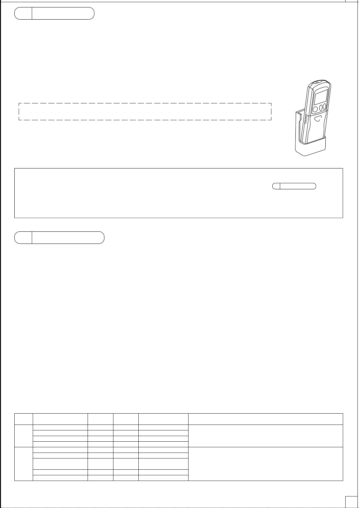
2 Confirming the Supplied Parts
Check that the box includes the following parts in addition to this installation manual:
Wireless remote controller
Remote controller holder
AAA alkaline battery
Tapping screws 4.1 × 16
Instruction book
Only use AAA batteries (LR03). Replace low batteries with new AAA batteries (LR03). Observe the polarity of the batteries as indicated, and insert the
negative end first.
Parts Name
Quantity
1
1
2
2
2
Do not install in any steamy place such a bathroom or kitchen.
Avoid any place where moisture is condensed into dew. Doing so may cause an
electric shock or a malfunction.
Do not install in any place where acidic or alkaline solution or special
spray are often used.
Doing so may cause an electric shock or malfunction.
Do not touch any circuit board with your hands or with tools. Do not allow
dust to collect on the circuit board.
Doing so may cause fire or an electric shock.
Do not touch any control button with your wet hands.
Doing so may cause an electric shock or a malfunction.
Do not press any control button using a sharp object.
Doing so may cause an electric shock or a malfunction.
1
Page 2
AAA
CLOCK
CHECK
RESET
SET
TEST RUN
MODE
FAN
VANE
LOUVER
min
h
AUTO START
AUTO STOP
ON/OFF
TEMP
MODEL SELECT
AAA
AAA
CLOCK
CHECK
RESET
SET
TEST RUN
MODE
FAN
VANE
LOUVER
min
h
AUTO START
AUTO STOP
ON/OFF
TEMP
MODEL SELECT
1.Fan speed
2.Louver swing
(horizontal air
direction control)
3.Vane
(vertical air
direction control)
Model number
14 speeds
23 speeds
32 speeds
4Fixed speed
1Disabled
2Enabled
1
Adjustable vane/Auto swing enabled
2
Adjustable vane/Auto swing disabled
3Fixed
4Undefined (Fixed)
1Cool/Dry/Auto/Fan/Heat
2Cool/Dry/Fan
3Cool/Dry/Auto/Heat
4
Cool/Dry/Auto/Fan/Combustion Heat/Heat
5Cool/Fan
6Cool/Auto/Fan/Heat
7Cool/Fan/Heat
8Cool/Dry/Fan/Heat
001 002 003 004 005 006 007 008 009 010 011 012 013 014 015 016 017 018 019 020 021 022 023 024 025 026 027 028 029 030 031 032 033 034 035 036 037 038 039 040 041 042 043
4.Operation
mode
Table of Model Numbers
Cooling/
heating Type
Indoor unit model name (Only the prototypes are shown.)
001
019
020
023
002
009
015
017
Cooling/
Heating Type
(Cool/Dry/Auto/
Fan/Heat)
Factory
setting
Model
No.
Cooling/
heating Type
Indoor unit model name (Only the prototypes are shown.)
033
051
052
055
034
041
047
049
Cooling only
type
(Cool/Dry/Fan)
Model
No.
CITY MULTI system
PLFY-AM model
PLFY-JM model
PMFY-BM model
PCFY-GM model
PKFY-AM model
PKFY-GM model
PLFY-LMD (22~112) model
PLFY-LMD (140) model
PMFY-EM model
PDFY-M (22~80) model
PCFY-HM model
PDFY-M (90~140 ) model
PEFY-AM model
PEFY-M (45~160) model
PFFY-LEM model
PFFY-LRM model
PEFY-M (224~280) model
PFFY-DM model
PSFY-GM model
CITY MULTI system
PLFY-AM model
PLFY-JM model
PMFY-BM model
PCFY-GM model
PKFY-AM model
PKFY-GM model
PLFY-LMD (22~112) model
PLFY-LMD (140) model
PMFY-EM model
PDFY-M (22~80) model
PCFY-HM model
PDFY-M (90~140) model
PEFY-AM model
PEFY-M (45~160) model
PFFY-LEM model
PFFY-LRM model
PEFY-M (224~280) model
PFFY-DM model
PSFY-GM model
Table of Model Numbers
3 Installation
MODEL SELECT
MODEL SELECT
1.Fan speed
2.Louver swing
(horizontal air
direction control)
3.Vane
(vertical air
direction control)
Model number
14 speeds
23 speeds
32 speeds
4Fixed speed
1Disabled
2Enabled
1
Adjustable vane/Auto swing enabled
2
Adjustable vane/Auto swing disabled
3Fixed
4Undefined (Fixed)
1Cool/Dry/Auto/Fan/Heat
2Cool/Dry/Fan
3Cool/Dry/Auto/Heat
4
Cool/Dry/Auto/Fan/Combustion Heat/Heat
5Cool/Fan
6Cool/Auto/Fan/Heat
7Cool/Fan/Heat
8Cool/Dry/Fan/Heat
4.Operation
mode
044 045 046 047 048 049 050 051 052 053 054 055 056 057 058 059 060 061 062 063 064 065 066 067 068 069 070 071 072 073 074 075 076 077 078 079 080 081 082 083 084 085 086
1.Fan speed
2.Louver swing
(horizontal air
direction control)
3.Vane
(vertical air
direction control)
Model number
14 speeds
23 speeds
32 speeds
4Fixed speed
1Disabled
2Enabled
1
Adjustable vane/Auto swing enabled
2
Adjustable vane/Auto swing disabled
3Fixed
4Undefined (Fixed)
1Cool/Dry/Auto/Fan/Heat
2Cool/Dry/Fan
3Cool/Dry/Auto/Heat
4
Cool/Dry/Auto/Fan/Combustion Heat/Heat
5Cool/Fan
6Cool/Auto/Fan/Heat
7Cool/Fan/Heat
8Cool/Dry/Fan/Heat
4.Operation
mode
087 088 089 090 091 092 093 094 095 096 097 098 099 100 101 102 103 104 105 106 107 108 109 110 111 112 113 114 115 116 117 118 119 120 121 122 123 124 125 126 127 128 129
1.Fan speed
2.Louver swing
(horizontal air
direction control)
3.Vane
(vertical air
direction control)
Model number
14 speeds
23 speeds
32 speeds
4Fixed speed
1Disabled
2Enabled
1
Adjustable vane/Auto swing enabled
2
Adjustable vane/Auto swing disabled
3Fixed
4Undefined (Fixed)
1Cool/Dry/Auto/Fan/Heat
2Cool/Dry/Fan
3Cool/Dry/Auto/Heat
4
Cool/Dry/Auto/Fan/Combustion Heat/Heat
5Cool/Fan
6Cool/Auto/Fan/Heat
7Cool/Fan/Heat
8Cool/Dry/Fan/Heat
4.Operation
mode
130 131 132 133 134 135 136 137 138 139 140 141 142 143 144 145 146 147 148 149 150 151 152 153 154 155 156 157 158 159 160 161 162 163 164 165 166 167 168 169 170 171 172
1.Fan speed
2.Louver swing
(horizontal air
direction control)
3.Vane
(vertical air
direction control)
Model number
14 speeds
23 speeds
32 speeds
4Fixed speed
1Disabled
2Enabled
1
Adjustable vane/Auto swing enabled
2
Adjustable vane/Auto swing disabled
3Fixed
4Undefined (Fixed)
1Cool/Dry/Auto/Fan/Heat
2Cool/Dry/Fan
3Cool/Dry/Auto/Heat
4
Cool/Dry/Auto/Fan/Combustion Heat/Heat
5Cool/Fan
6Cool/Auto/Fan/Heat
7Cool/Fan/Heat
8Cool/Dry/Fan/Heat
4.Operation
mode
173 174 175 176 177 178 179 180 181 182 183 184 185 186 187 188 189 190 191 192 193 194 195 196 197 198 199 200 201 202 203 204 205 206 207 208 209 210 211 212 213 214 215
1.Fan speed
2.Louver swing
(horizontal air
direction control)
3.Vane
(vertical air
direction control)
Model number
14 speeds
23 speeds
32 speeds
4Fixed speed
1Disabled
2Enabled
1
Adjustable vane/Auto swing enabled
2
Adjustable vane/Auto swing disabled
3Fixed
4Undefined (Fixed)
1Cool/Dry/Auto/Fan/Heat
2Cool/Dry/Fan
3Cool/Dry/Auto/Heat
4
Cool/Dry/Auto/Fan/Combustion Heat/Heat
5Cool/Fan
6Cool/Auto/Fan/Heat
7Cool/Fan/Heat
8Cool/Dry/Fan/Heat
4.Operation
mode
216 217 218 219 220 221 222 223 224 225 226 227 228 229 230 231 232 233 234 235 236 237 238 239 240 241 242 243 244 245 246 247 248 249 250 251 252 253 254 255 256
MODEL SELECT
NOT AVAILABLE
MODEL SELECT
TEST RUN
CHECK
185
4
2
3
9
7
6
TEST RUN
MODE
FAN
VANE
TEST RUN
TEST RUN
CHECK
h
CHECK
“0”
“0”
“1”
“1”
“2”
“2”
“0”
“0”
“0”
“0”
“0”
“0”
“0”
“0”
AAA
CLOCK
CHECK
RESET
SET
TEST RUN
MODE
FAN
VANE
LOUVER
min
h
AUTO START
AUTO STOP
ON/OFF
TEMP
TEST RUN
CLOCK
CHECK
RESET
SET
TEST RUN
MODE
FAN
VANE
LOUVER
min
h
AUTO START
AUTO STOP
ON/OFF
TEMP
CHECK
■ Use the remote controller holder that is provided to avoid misplacing the remote controller.
■ Install the remote controller in a location that meets the following conditions.
• Out of the direct sun light
• Away from any heat sources
• Out of the airflow from the air conditioner (cool or warm)
• Where the operation of the remote controller can easily be performed and the display is readily visible to the user
• Out of the reach of small children
NOTES:
* If there is a fluorescent light in the room in which the air conditioner is to be installed, turn it on and make sure that the
signal from the remote controller can be received by the indoor unit from the intended installation location. When the
signal receiving unit receives a signal from the remote controller, a short beeping sound will be heard.
If the air conditioner unit is installed in a room in which a fluorescent light on an electronic lighting control system
(i.e., inverter light) is installed, signal interference may occur.
* Maximum signal receiving distance is approximately 7 meters (Approx. 22 feet). Signal receiving angle is approxi-
mately 45 degrees to the right and the left from the center.
* Install the unit at least 1 meter (Approx. 3 feet) away from the TV or radio.
(If the unit is installed too close to these appliances, signal interference (picture distortion and noise) may occur.)
■ Use the tapping screws that are provided to mount the remote controller holder on the wall, and then place the
remote controller in the holder.
NOTES:
• Some older versions of signal receiving unit may not respond to the signals from the remote controller that correspond to the following
functions. If this happens, set the model setting on the remote controller to “Standard 2 °F” as shown in section “ 4 Model Setting .”
<Functions not supported by older versions of signal receiving unit >
• Temperature setting in 1 °F increments.
• Control operations that are performed on the controller with the setting other than “Standard 2 °F”.
4 Model Setting
Model setting must be made to control indoor units.
Register the model of the indoor unit to be controlled on the Model Select menu. Correct indoor unit model must be registered on the remote controller
to control the indoor unit. Collectively set items need to be set for each group of indoor units with the same pattern of functions. Individually set items
usually do not need to be changed.
■ Remote controller setting
There are three ways to make remote controller settings as follows.
1. Check the model of the indoor unit to be controlled from the wireless remote controller, and find the corresponding
model number of the wireless remote controller in the table of model numbers. (Collective setting)
2. If the name of the indoor unit to be controlled is not listed in the table of model numbers, check the available functions of
the indoor unit in a technical manual and follow one of the following procedures to make the settings for the remote
controller.
1 Model No. Find the model number of the unit that has the same functions as the unit to be installed and register that
model number (Collective setting).
2 Model No. Make the setting for certain functions individually without referring to the table (Individual setting).
3. Whether items 1 or 2 above apply or not, when the settings must be made for items that cannot be set collectively, make
the settings for those items individually.
■ Setting items
There are two types of setting items
• Collectively set items
• Individually set items
Items that can be set collectively can also be set individually. (If the setting for each item is individually entered, the model number that corresponds to
the same pattern of settings will appear on the display.)
<Collectively and individually set items>
* 1: Cool/Dry/Auto/Fan/Heat
items
Collec-
tively set
items
Individually set
Setting items
No. of fan speeds
Louver swing
Vane
Operation mode
Auto fan speed control
Preset temperature
Temperature display in °C
and °F
Pair No.
Model
Collective
setting
Ye s
Ye s
Ye s
Ye s
No
No
No
No
No
Individual
setting
Ye s
Ye s
Ye s
Ye s
Ye s
Ye s
Ye s
Ye s
Ye s
Initial setting
4 speeds
Disabled
Auto swing enabled
Heat pump model *1
Disabled
Settable
Centigrade
0
Standard model
When the model number is available, these settings do not need to be set
individually.
The initial setting for the model setting is “No. 001.”
These settings cannot be set collectively and must be set individually.
Make the setting as necessary.
• Changing the setting for these items does not change the model number that
appears on the remote controller.
• These items are not automatically set when the settings for collectively set
items are made.
Remarks
→ Step 1
→ Step 2
→ Step 3
→ Step 3
2
Page 3
AAA
CLOCK
CHECK
RESET
SET
TEST RUN
MODE
FAN
VANE
LOUVER
min
h
AUTO START
AUTO STOP
ON/OFF
TEMP
MODEL SELECT
AAA
AAA
CLOCK
CHECK
RESET
SET
TEST RUN
MODE
FAN
VANE
LOUVER
min
h
AUTO START
AUTO STOP
ON/OFF
TEMP
MODEL SELECT
1.Fan speed
2.Louver swing
(horizontal air
direction control)
3.Vane
(vertical air
direction control)
Model number
14 speeds
23 speeds
32 speeds
4Fixed speed
1Disabled
2Enabled
1
Adjustable vane/Auto swing enabled
2
Adjustable vane/Auto swing disabled
3Fixed
4Undefined (Fixed)
1Cool/Dry/Auto/Fan/Heat
2Cool/Dry/Fan
3Cool/Dry/Auto/Heat
4
Cool/Dry/Auto/Fan/Combustion Heat/Heat
5Cool/Fan
6Cool/Auto/Fan/Heat
7Cool/Fan/Heat
8Cool/Dry/Fan/Heat
001 002 003 004 005 006 007 008 009 010 011 012 013 014 015 016 017 018 019 020 021 022 023 024 025 026 027 028 029 030 031 032 033 034 035 036 037 038 039 040 041 042 043
4.Operation
mode
Table of Model Numbers
Cooling/
heating Type
Indoor unit model name (Only the prototypes are shown.)
001
019
020
023
002
009
015
017
Cooling/
Heating Type
(Cool/Dry/Auto/
Fan/Heat)
Factory
setting
Model
No.
Cooling/
heating Type
Indoor unit model name (Only the prototypes are shown.)
033
051
052
055
034
041
047
049
Cooling only
type
(Cool/Dry/Fan)
Model
No.
CITY MULTI system
PLFY-AM model
PLFY-JM model
PMFY-BM model
PCFY-GM model
PKFY-AM model
PKFY-GM model
PLFY-LMD (22~112) model
PLFY-LMD (140) model
PMFY-EM model
PDFY-M (22~80) model
PCFY-HM model
PDFY-M (90~140 ) model
PEFY-AM model
PEFY-M (45~160) model
PFFY-LEM model
PFFY-LRM model
PEFY-M (224~280) model
PFFY-DM model
PSFY-GM model
CITY MULTI system
PLFY-AM model
PLFY-JM model
PMFY-BM model
PCFY-GM model
PKFY-AM model
PKFY-GM model
PLFY-LMD (22~112) model
PLFY-LMD (140) model
PMFY-EM model
PDFY-M (22~80) model
PCFY-HM model
PDFY-M (90~140) model
PEFY-AM model
PEFY-M (45~160) model
PFFY-LEM model
PFFY-LRM model
PEFY-M (224~280) model
PFFY-DM model
PSFY-GM model
Table of Model Numbers
● Step 1
MODEL SELECT
MODEL SELECT
1.Fan speed
2.Louver swing
(horizontal air
direction control)
3.Vane
(vertical air
direction control)
Model number
14 speeds
23 speeds
32 speeds
4Fixed speed
1Disabled
2Enabled
1
Adjustable vane/Auto swing enabled
2
Adjustable vane/Auto swing disabled
3Fixed
4Undefined (Fixed)
1Cool/Dry/Auto/Fan/Heat
2Cool/Dry/Fan
3Cool/Dry/Auto/Heat
4
Cool/Dry/Auto/Fan/Combustion Heat/Heat
5Cool/Fan
6Cool/Auto/Fan/Heat
7Cool/Fan/Heat
8Cool/Dry/Fan/Heat
4.Operation
mode
216 217 218 219 220 221 222 223 224 225 226 227 228 229 230 231 232 233 234 235 236 237 238 239 240 241 242 243 244 245 246 247 248 249 250 251 252 253 254 255 256
MODEL SELECT
TEST RUN
MODE
FAN
VANE
TEST RUN
TEST RUN
“0”
“0”
“1”
“1”
“2”
“2”
“0”
“0”
“0”
“0”
“0”
“0”
“0”
“0”
AAA
CLOCK
CHECK
RESET
SET
TEST RUN
MODE
FAN
VANE
LOUVER
min
h
AUTO START
AUTO STOP
ON/OFF
TEMP
TEST RUN
1. Check the model of the indoor unit to be controlled from the wireless remote controller.
2. Refer to the table of model numbers and find the model number that corresponds to the model of indoor unit to be controlled. Make the settings
according to the operation procedures.
Note 1: If the settings that are related to the remote controller operation are changed on the function selection menu, make the setting for the model
number by referring to the table of model numbers.
(i.e., Changes to the vane adjustment setting (Function selection mode 11) or Swing setting (Function selection mode 23))
Note 2: Some indoor units with the same model name may have different functions, depending on the capacity type and production year. Refer to the
applicable technical document to confirm the functions that are available to a given unit, and make an appropriate setting for the model number
according to the table of model numbers.
Note 3: To set the model number for the indoor unit that is not listed in the table above, check the functions that are available to it in the applicable
technical document, and make an appropriate setting for the model number according to the table of model numbers.
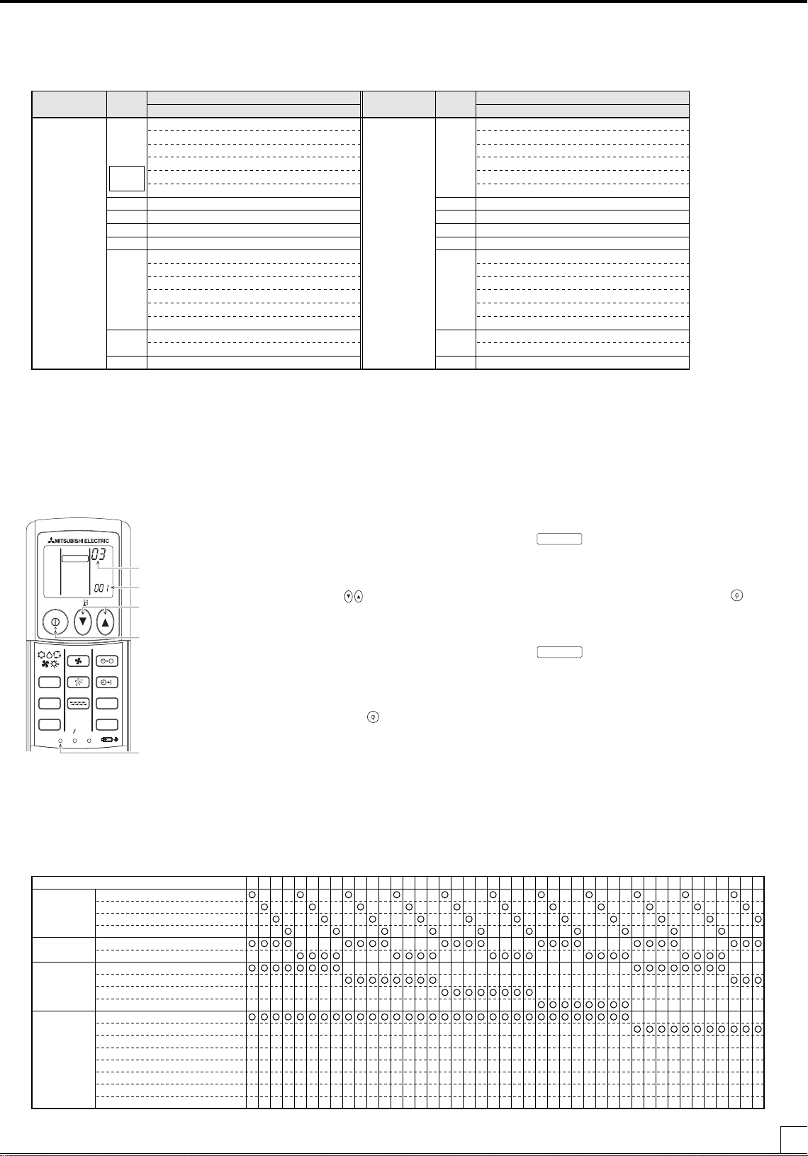
[Setting Procedures]
Setting No.
Model No.
TEMP buttons
1. Push the SET button with a pointed but not sharp
object.
Make sure that the remote controller display indicates that the unit is stopped.
2. Use the TEMP buttons to set the model number.
•
be lit. (It is set to “001” at factory shipment.)
• If an error is made, press the ON/OFF
to cancel, and enter the model number again.
will blink, and model number “001” will
Functions that correspond to each model num-
ON/OFF
button
ber will appear on the display.
3. Press the set button again with a pointed but not
sharp object.
•
and the model number that was entered
will stay lit for three seconds and then go off.
• Press the ON/OFF button to turn on the remote controller display, and confirm that the model number is correctly set.
SET button
● Step 2
1. Refer to the applicable technical document to confirm the functions that are available to a given unit, and make an appropriate setting by finding the
model number that corresponds to the pattern of those available functions.
2. Setting procedures are the same for those listed under Step 1.
button
3
Page 4

AAA
CLOCK
CHECK
RESET
SET
TEST RUN
MODE
FAN
VANE
LOUVER
min
h
AUTO START
AUTO STOP
ON/OFF
TEMP
MODEL SELECT
AAA
AAA
CLOCK
CHECK
RESET
SET
TEST RUN
MODE
FAN
VANE
LOUVER
min
h
AUTO START
AUTO STOP
ON/OFF
TEMP
MODEL SELECT
1.Fan speed
2.Louver swing
(horizontal air
direction control)
3.Vane
(vertical air
direction control)
Model number
14 speeds
23 speeds
32 speeds
4Fixed speed
1Disabled
2Enabled
1
Adjustable vane/Auto swing enabled
2
Adjustable vane/Auto swing disabled
3Fixed
4Undefined (Fixed)
1Cool/Dry/Auto/Fan/Heat
2Cool/Dry/Fan
3Cool/Dry/Auto/Heat
4
Cool/Dry/Auto/Fan/Combustion Heat/Heat
5Cool/Fan
6Cool/Auto/Fan/Heat
7Cool/Fan/Heat
8Cool/Dry/Fan/Heat
001 002 003 004 005 006 007 008 009 010 011 012 013 014 015 016 017 018 019 020 021 022 023 024 025 026 027 028 029 030 031 032 033 034 035 036 037 038 039 040 041 042 043
4.Operation
mode
Table of Model Numbers
Cooling/
heating Type
Indoor unit model name (Only the prototypes are shown.)
001
019
020
023
002
009
015
017
Cooling/
Heating Type
(Cool/Dry/Auto/
Fan/Heat)
Factory
setting
Model
No.
Cooling/
heating Type
Indoor unit model name (Only the prototypes are shown.)
033
051
052
055
034
041
047
049
Cooling only
type
(Cool/Dry/Fan)
Model
No.
CITY MULTI system
PLFY-AM model
PLFY-JM model
PMFY-BM model
PCFY-GM model
PKFY-AM model
PKFY-GM model
PLFY-LMD (22~112) model
PLFY-LMD (140) model
PMFY-EM model
PDFY-M (22~80) model
PCFY-HM model
PDFY-M (90~140 ) model
PEFY-AM model
PEFY-M (45~160) model
PFFY-LEM model
PFFY-LRM model
PEFY-M (224~280) model
PFFY-DM model
PSFY-GM model
CITY MULTI system
PLFY-AM model
PLFY-JM model
PMFY-BM model
PCFY-GM model
PKFY-AM model
PKFY-GM model
PLFY-LMD (22~112) model
PLFY-LMD (140) model
PMFY-EM model
PDFY-M (22~80) model
PCFY-HM model
PDFY-M (90~140) model
PEFY-AM model
PEFY-M (45~160) model
PFFY-LEM model
PFFY-LRM model
PEFY-M (224~280) model
PFFY-DM model
PSFY-GM model
Table of Model Numbers
MODEL SELECT
MODEL SELECT
1.Fan speed
2.Louver swing
(horizontal air
direction control)
3.Vane
(vertical air
direction control)
Model number
14 speeds
23 speeds
32 speeds
4Fixed speed
1Disabled
2Enabled
1
Adjustable vane/Auto swing enabled
2
Adjustable vane/Auto swing disabled
3Fixed
4Undefined (Fixed)
1Cool/Dry/Auto/Fan/Heat
2Cool/Dry/Fan
3Cool/Dry/Auto/Heat
4
Cool/Dry/Auto/Fan/Combustion Heat/Heat
5Cool/Fan
6Cool/Auto/Fan/Heat
7Cool/Fan/Heat
8Cool/Dry/Fan/Heat
4.Operation
mode
044 045 046 047 048 049 050 051 052 053 054 055 056 057 058 059 060 061 062 063 064 065 066 067 068 069 070 071 072 073 074 075 076 077 078 079 080 081 082 083 084 085 086
1.Fan speed
2.Louver swing
(horizontal air
direction control)
3.Vane
(vertical air
direction control)
Model number
14 speeds
23 speeds
32 speeds
4Fixed speed
1Disabled
2Enabled
1
Adjustable vane/Auto swing enabled
2
Adjustable vane/Auto swing disabled
3Fixed
4Undefined (Fixed)
1Cool/Dry/Auto/Fan/Heat
2Cool/Dry/Fan
3Cool/Dry/Auto/Heat
4
Cool/Dry/Auto/Fan/Combustion Heat/Heat
5Cool/Fan
6Cool/Auto/Fan/Heat
7Cool/Fan/Heat
8Cool/Dry/Fan/Heat
4.Operation
mode
087 088 089 090 091 092 093 094 095 096 097 098 099 100 101 102 103 104 105 106 107 108 109 110 111 112 113 114 115 116 117 118 119 120 121 122 123 124 125 126 127 128 129
1.Fan speed
2.Louver swing
(horizontal air
direction control)
3.Vane
(vertical air
direction control)
Model number
14 speeds
23 speeds
32 speeds
4Fixed speed
1Disabled
2Enabled
1
Adjustable vane/Auto swing enabled
2
Adjustable vane/Auto swing disabled
3Fixed
4Undefined (Fixed)
1Cool/Dry/Auto/Fan/Heat
2Cool/Dry/Fan
3Cool/Dry/Auto/Heat
4
Cool/Dry/Auto/Fan/Combustion Heat/Heat
5Cool/Fan
6Cool/Auto/Fan/Heat
7Cool/Fan/Heat
8Cool/Dry/Fan/Heat
4.Operation
mode
130 131 132 133 134 135 136 137 138 139 140 141 142 143 144 145 146 147 148 149 150 151 152 153 154 155 156 157 158 159 160 161 162 163 164 165 166 167 168 169 170 171 172
1.Fan speed
2.Louver swing
(horizontal air
direction control)
3.Vane
(vertical air
direction control)
Model number
14 speeds
23 speeds
32 speeds
4Fixed speed
1Disabled
2Enabled
1
Adjustable vane/Auto swing enabled
2
Adjustable vane/Auto swing disabled
3Fixed
4Undefined (Fixed)
1Cool/Dry/Auto/Fan/Heat
2Cool/Dry/Fan
3Cool/Dry/Auto/Heat
4
Cool/Dry/Auto/Fan/Combustion Heat/Heat
5Cool/Fan
6Cool/Auto/Fan/Heat
7Cool/Fan/Heat
8Cool/Dry/Fan/Heat
4.Operation
mode
173 174 175 176 177 178 179 180 181 182 183 184 185 186 187 188 189 190 191 192 193 194 195 196 197 198 199 200 201 202 203 204 205 206 207 208 209 210 211 212 213 214 215
1.Fan speed
2.Louver swing
(horizontal air
direction control)
3.Vane
(vertical air
direction control)
Model number
14 speeds
23 speeds
32 speeds
4Fixed speed
1Disabled
2Enabled
1
Adjustable vane/Auto swing enabled
2
Adjustable vane/Auto swing disabled
3Fixed
4Undefined (Fixed)
1Cool/Dry/Auto/Fan/Heat
2Cool/Dry/Fan
3Cool/Dry/Auto/Heat
4
Cool/Dry/Auto/Fan/Combustion Heat/Heat
5Cool/Fan
6Cool/Auto/Fan/Heat
7Cool/Fan/Heat
8Cool/Dry/Fan/Heat
4.Operation
mode
216 217 218 219 220 221 222 223 224 225 226 227 228 229 230 231 232 233 234 235 236 237 238 239 240 241 242 243 244 245 246 247 248 249 250 251 252 253 254 255 256
MODEL SELECT
NOT AVAILABLE
MODEL SELECT
TEST RUN
CHECK
185
4
2
3
9
7
6
TEST RUN
MODE
FAN
VANE
TEST RUN
TEST RUN
CHECK
h
CHECK
“0”
“0”
“1”
“1”
“2”
“2”
“0”
“0”
“0”
“0”
“0”
“0”
“0”
“0”
AAA
CLOCK
CHECK
RESET
SET
TEST RUN
MODE
FAN
VANE
LOUVER
min
h
AUTO START
AUTO STOP
ON/OFF
TEMP
TEST RUN
CLOCK
CHECK
RESET
SET
TEST RUN
MODE
FAN
VANE
LOUVER
min
h
AUTO START
AUTO STOP
ON/OFF
TEMP
CHECK
4
Page 5

AAA
CLOCK
CHECK
RESET
SET
TEST RUN
MODE
FAN
VANE
LOUVER
min
h
AUTO START
AUTO STOP
ON/OFF
TEMP
MODEL SELECT
● Step 3
1.Fan speed
2.Louver swing
(horizontal air
direction control)
3.Vane
(vertical air
direction control)
Model number
14 speeds
23 speeds
32 speeds
4Fixed speed
1Disabled
2Enabled
1
Adjustable vane/Auto swing enabled
2
Adjustable vane/Auto swing disabled
3Fixed
4Undefined (Fixed)
1Cool/Dry/Auto/Fan/Heat
2Cool/Dry/Fan
3Cool/Dry/Auto/Heat
4
Cool/Dry/Auto/Fan/Combustion Heat/Heat
5Cool/Fan
6Cool/Auto/Fan/Heat
7Cool/Fan/Heat
8Cool/Dry/Fan/Heat
4.Operation
mode
216 217 218 219 220 221 222 223 224 225 226 227 228 229 230 231 232 233 234 235 236 237 238 239 240 241 242 243 244 245 246 247 248 249 250 251 252 253 254 255 256
MODEL SELECT
TEST RUN
MODE
FAN
VANE
TEST RUN
TEST RUN
“0”
“0”
“1”
“1”
“2”
“2”
“0”
“0”
“0”
“0”
“0”
“0”
“0”
“0”
AAA
CLOCK
CHECK
RESET
SET
TEST RUN
MODE
FAN
VANE
LOUVER
min
h
AUTO START
AUTO STOP
ON/OFF
TEMP
TEST RUN
1. Refer to the applicable technical document to confirm the functions that are available to a given indoor unit, and manually make individual settings one
by one without referring to the table of unit models.
2. Make the settings for individually set items as necessary.
[Setting Procedures]
1. Press the SET button with a pointed but not sharp object.
Make sure that the remote controller display indicates that the unit is stopped.
will blink, and the model number (a three-digit figure) will be lit.
(Collective setting mode in Steps 1 and 2)
2. Refer to the Table of Individually Set Items and Buttons, and press the button that corresponds to an
applicable individually set item only once.
The value to be changed will blink, and the setting number will be lit.
(When setting the pair number, the pair number will blink in the setting number window.)
3. Press the TEMP
buttons to set the setting number.
Settings that correspond to each setting number will appear on the display.
* If an error is made, press the ON/OFF
button to cancel all the settings for the individual settings and
go back to Step 1 above (collective setting mode). Start over from the second step above.
* If the settings for the collectively set items are made individually, the model number that corresponds to
the unit with the same patterns of functions will appear on the display.
4. Repeat Steps 2 and 3 above to make other settings.
5. Press the SET button to store these settings. The display will stay lit for three seconds and then go off.
* If the settings for collectively set items are made individually, the model number will automatically be
changed.
<Table of Individually Set Items and Buttons> (Underlined values indicate initial settings.)
Setting Item
No. of fan speeds
Button
FAN
01: 4 Speeds (Very Low, Low, Mid, High) 02: 3 Speeds (Low, Mid, High)
03: 2 Speeds (Low, High) 04: Fixed Speed
Louver swing
Vane
LOUVER
VAN E
01: Disabled 02: Enabled
01: Adjustable vane/Auto swing enabled
02: Adjustable vane/Auto swing disabled
03: Fixed
Operation mode
MODE
01: Heat pump model (Cool/Dry/Auto/Fan/Heat)
02: Cooling-only model (Cool/Dry/Fan)
03: New K-control Heat pump model (Cool/Dry/Auto/Heat)
04: Not to be selected
05: Cooling-only model (without Dry mode) (Cool/Fan)
06: Heat pump model (without Dry mode)(Cool/Auto/Fan/Heat)
07: Heat pump model (without Dry or Auto mode)(Cool/Fan/Heat)
08: K-control Heat pump model (Cool/Dry/Fan/Heat)
Auto fan speed control
Preset temperature
Display in Centigrade/
AUTO STOP
h
AUTO START
01: Disabled 02: Enabled
01: Available 02: Unavailable
01: °C 02: °F
Fahrenheit
Pair No.
Model*1
min.
CHECK
0 ~ 9
01: Standard (2 °F) 02: Standard (1 °F)
03: SLIM middle temperature 04: CITY MULTI middle temperature
05: Low temperature 06: RAC
*1 Fix this setting to “01” when sending signals to a signal receiving unit other than PAR-FA32MA.
Setting No.
Setting No.
Model No.
TEMP buttons
ON/OFF button
SET button
5
Page 6

AAA
CLOCK
CHECK
RESET
SET
TEST RUN
MODE
FAN
VANE
LOUVER
min
h
AUTO START
AUTO STOP
ON/OFF
TEMP
MODEL SELECT
1.Fan speed
2.Louver swing
(horizontal air
direction control)
3.Vane
(vertical air
direction control)
Model number
14 speeds
23 speeds
32 speeds
4Fixed speed
1Disabled
2Enabled
1
Adjustable vane/Auto swing enabled
2
Adjustable vane/Auto swing disabled
3Fixed
4Undefined (Fixed)
1Cool/Dry/Auto/Fan/Heat
2Cool/Dry/Fan
3Cool/Dry/Auto/Heat
4
Cool/Dry/Auto/Fan/Combustion Heat/Heat
5Cool/Fan
6Cool/Auto/Fan/Heat
7Cool/Fan/Heat
8Cool/Dry/Fan/Heat
4.Operation
mode
216 217 218 219 220 221 222 223 224 225 226 227 228 229 230 231 232 233 234 235 236 237 238 239 240 241 242 243 244 245 246 247 248 249 250 251 252 253 254 255 256
MODEL SELECT
<Display of individually set items>
NOT AVAILABLE
MODEL SELECT
TEST RUN
CHECK
185
4
2
3
9
7
6
TEST RUN
MODE
FAN
VANE
TEST RUN
TEST RUN
CHECK
h
CHECK
“0”
“0”
“1”
“1”
“2”
“2”
“0”
“0”
“0”
“0”
“0”
“0”
“0”
“0”
AAA
CLOCK
CHECK
RESET
SET
TEST RUN
MODE
FAN
VANE
LOUVER
min
h
AUTO START
AUTO STOP
ON/OFF
TEMP
TEST RUN
CLOCK
CHECK
RESET
SET
TEST RUN
MODE
FAN
VANE
LOUVER
min
h
AUTO START
AUTO STOP
ON/OFF
TEMP
CHECK
Display will change with the change in the setting number.
■ No. of Fan speeds 1
01: 4 speeds 02: 3 speeds 03: 2 speeds 04: Fixed speed
■ Louver swing 2
01: Disabled 02: Enabled
No display
■ Vane 3
01: Adjustable vane/Auto swing enabled 02: Adjustable vane/Auto swing disabled 03: Fixed
■ Operation mode 4
01: Heat pump model 02: Cooling-only model
COOL COOL
DRY DRY
AUTO
FAN FAN
HEAT
03: K-control heat pump model 04: Not to be selected
COOL
DRY
AUTO
HEAT
05: Cooling-only model (without Dry mode) 06: Heat pump model (without Dry mode)
COOL COOL
DRY
AUTO
FAN FAN
07: Heat pump model (without Dry or Auto modes) 08: K-control heat pump model
COOL COOL
DRY
No display
FAN FAN
HEAT HEAT
■ Auto fan speed control 5 ■ Preset temperature 6
01: Disabled 02: Enabled 01: Available 02: Unavailable
No display °F
°C
No display
■ Temperature display in Centigrade and Fahrenheit (Displayed in the hour section of the clock) 7
01: °C 02: °F
■ Pair No. (Displayed in the preset temperature window) 8
0 ~ 9
■ Model (Displayed in the minute section of the clock) 9
01: Standard (2 °F) 02: Standard (1 °F) 03: SLIM middle temperature
04: CITY MULTI middle temperature 05: Low temperature 06: RAC
Unless this setting is set to “01,” preset temperature can be changed in 1 °F increments when “temperature display in Fahrenheit” is selected.
By setting the model type, preset temperature range will be defined as in the table below.
Setting
01
02
03
04
05
06
Standard 2 °F model
Standard 1 °F model
Middle
temperature model
Low temperature model
RAC model
Model
Both SLIM and CITY MULTI
models
Both SLIM and CITY MULTI
models
SLIM model
CITY MULTI model
Both SLIM and CITY MULTI
models
–
Centigrade/
Fahrenheit
Centigrade
Fahrenheit
Centigrade
Fahrenheit
Centigrade
Fahrenheit
Centigrade
Fahrenheit
Centigrade
Fahrenheit
Centigrade
Fahrenheit
Setting increments
1 °C
2 °F
1 °C
1 °F
1 °C
1 °F
1 °C
1 °F
1 °C
1 °F
1 °C
1 °F
Cool/Dry
19 ~ 30 °C
67 ~ 87 °F
19 ~ 30 °C
67 ~ 87 °F
14 ~ 30 °C
57 ~ 87 °F
14 ~ 30 °C
57 ~ 87 °F
8 ~ 30 °C
46 ~ 87 °F
Heat
17 ~ 28 °C
63 ~ 83 °F
17 ~ 28 °C
63 ~ 83 °F
16 ~ 31 °C
61 ~ 88 °F
Auto
19 ~ 28 °C
67 ~ 83 °F
19 ~ 28 °C
67 ~ 83 °F
14 ~ 28 °C
57 ~ 83 °F
17 ~ 28 °C
63 ~ 83 °F
8 ~ 28 °C
46 ~ 83 °F
6
Page 7

5 Pair Number Setting
TEST RUN
MODE
FAN
VANE
TEST RUN
TEST RUN
“0”
“0”
“1”
“1”
“2”
“2”
“0”
“0”
“0”
“0”
“0”
“0”
“0”
“0”
AAA
CLOCK
CHECK
RESET
SET
TEST RUN
MODE
FAN
VANE
LOUVER
min
h
AUTO START
AUTO STOP
ON/OFF
TEMP
TEST RUN
• Pair number setting is required to pair up a certain signal receiving unit and a certain remote controller. This
setting is not necessary unless assigning a particular
indoor unit to a particular remote controller. (At factory
shipment, the pair number on the signal receiving unit
and wireless remote controller is set to “0.”)
• When this setting needs to be made, make the settings
on the signal receiving unit and the wireless remote controller as shown in the right table.
● Setting Example
(1) Controlling multiple units in the same room
• Individual setting
Each unit can be controlled from separate remote controllers.
(2) Controlling multiple units in different rooms
Set the signal receiving unit and wireless remote
controller in the same room to the same number.
(Use the factory setting as it is.)
Pair number setting on the wireless
remote controller
0
1
2
3
4
5
6
7
8
9
Set the pair number switch on the signal receiving unit.
In the case of CITY MULTI system
0
1
2
3
4
5
6
7
8
9
* Refer to the installation manual that comes with the signal receiving unit for details.
• Single-controller setting
All indoor units are controlled from a single remote controller.
6 Test Run Method
[Setting Procedures]
1. Turn on the power.
2. Press the
button twice con-
secutively.
ON/OFF button
FAN button
MODE button
3. Press the
4. Press the
5. Press the
6. Confirm that the outdoor unit fan
button.
button.
button.
is in operation.
TEST RUN button
7. Press the ON/OFF button
VANE button
or press the
button twice con-
secutively.
• 2-hour OFF timer will automatically stop the test run in two hours.
7 Operation Lamp Display and Buzzer
The following section details the operation lamp and the buzzer on the signal receiving unit.
<When receiving operation signals from the wireless remote controller>
Confirmation sound that indicates signal reception: Short beep
Operation lamp During operation: Lights off three times at 0.1-second intervals.
While the unit is stopped: Lights up three times at 0.1-second intervals.
* It will take three minutes after power on to start up the system.
•
and the operation setting will be displayed.
• Make sure that the remote controller display indicates that the
unit is stopped.
• Operation mode will change to and from Cool and Heat.
Cool: Confirm that cool air blows out.
Heat: Confirm that warm air blows out (It takes a while for warm air
to come out.)
• Confirm that the fan speed changes.
• Confirm the normal operation of auto-vane.
• Outdoor unit controls its capacity by controlling the rotation speed
of the fan. Depending on the outside air temperature, the fan runs
at low speed and stays at the speed as long as it has enough
power. Even if the fan stops or rotates in the reverse direction, it is
not a malfunction.
• Test run will be cancelled.
<If a wireless remote controller is operated while the units are under centralized control>
Depending on the settings, when local control is prohibited by the centralized control system, ON/OFF, Mode selection, or Temperature setting buttons
on the remote controller may be disabled.
Confirmation sound that indicates signal reception: Two staccato beeps
Operation lamp During operation: Lights off three times at 0.25-second intervals.
<When the preset temperature is corrected (Applicable to signal receiving unit PAR-FA32MA only)>
If the model setting on the wireless remote controller does not match the actual model type of the indoor unit that is connected, the signal receiving unit
will make correction on the preset temperature for the indoor unit. When this happens, signal receiving unit will perform the following actions.
Confirmation sound that indicates signal reception: Two staccato beeps
Operation lamp During operation: Lights off three times at 0.25-second intervals.
While the unit is stopped: Lights up three times at 0.25-second intervals.
While the unit is stopped: Lights up three times at 0.25-second intervals.
7
Page 8

TEST RUN
MODE
FAN
VANE
TEST RUN
TEST RUN
CHECK
CHECK
“0”
“0”
“1”
“1”
“2”
“2”
“0”
“0”
“0”
“0”
“0”
“0”
“0”
“0”
AAA
CLOCK
CHECK
RESET
SET
TEST RUN
MODE
FAN
VANE
LOUVER
min
h
AUTO START
AUTO STOP
ON/OFF
TEMP
TEST RUN
CLOCK
CHECK
RESET
SET
TEST RUN
MODE
FAN
VANE
LOUVER
min
h
AUTO START
AUTO STOP
ON/OFF
TEMP
CHECK
Reception of a signal from the wireless remote controller
Conditions
that corresponds to a preset temperature that is outside of
the setting range
The temperature setting will be corrected to the maximum or minimum settable temperature and set to the
indoor unit.
Example: When the setting range for the cooling operation of the indoor unit is between 19 °C and 30 °C
Action of the signal receiving unit
and the signal to set the cooling temperature to 17 °C is received from the wireless remote controller.
(Action) The signal receiving unit will read the temperature as 19 °C and set it to the indoor unit.)
Reception of a signal from the wireless remote controller
that corresponds to an even numbered temperature setting
in Fahrenheit when the connected indoor unit is not
compatible with temperature setting in 1 °F increments.
Even-numbered temperatures in Fahrenheit will be changed to odd-numbered temperatures in Fahrenheit
and set to the indoor unit.
Example: Reception of a signal that corresponds to 78 °F when the connected indoor unit is not compatible
with temperature setting in 1 °F increments.
(Action) The signal receiving unit will read 78 °F as 77 °F and set it to the indoor unit.)
<In case of a problem>
Operation lamp will blink, indicating a problem with the air conditioner. When this happens, turn off the power to the air conditioner, and consult your
dealer. Do not attempt to repair the unit by yourself.
<Making a self-diagnosis>
Refer to section 8 “Self-diagnosis.”
<Operating the emergency operation button on the signal receiving unit>
Confirmation sound that indicates signal reception: None
Operation lamp During operation: Unlit
While the unit is stopped: Lit
When local control is prohibited, remote controller will be disabled.
8 Self-Diagnosis
The following procedures are applicable to CITY MULTI air conditioners.
(The following procedures cannot be performed when the unit is in error.)
[Operating Procedures]
Refrigerant
address display
CHECK display
TEMP buttons
ON/OFF button
h button
CHECK button
1. Press the
2. Press the TEMP buttons.
3. Point the remote controller to the signal receiving unit, and press the h button.
4. Point the remote controller to the signal receiving unit, and press the ON/OFF button.
button twice.
*
will be lit, and refrigerant address “00” will blink.
• Make sure that the remote controller display indicates that the unit is stopped.
• Select the refrigerant address of the indoor unit to
be self-diagnosed.
• When a problem with the connected air conditioner
is detected, intermittent beeping sound will be heard
from the signal receiving unit, and a check code will
be output by the blinking of the operation lamp.
• Check mode will be cancelled.
<Output of Check Codes>
Indoor unit error
Error content
Errors unrelated to indoor unit
No error history
No applicable unit
Buzzer Sound
Beep × n times
Two short beeps × n times
No output
Three staccato beeps
Operation Lamp
One second × n times
(0.4 second +0.4 second) × n times
Unlit
Unlit
NOTES:
Refer to the instruction manual that
comes with the air conditioner for the
details of error codes.
Number(n) of beeps and blinking of operation lamp
Signal receiving unit will beep and the operation lamp will blink certain times, depending on the error code that is received from the indoor unit.
Number of beeps/blinking
8
1
2
3
4
5
6
7
9
This product is designed and intended for use in a residential, commercial or light-industrial environment.
CITY MULTI Error Code
0000 ~ 0999
1000 ~ 1999
2000 ~ 2999
3000 ~ 3999
4000 ~ 4999
5000 ~ 5999
6000 ~ 6999
7000 ~ 7999
8000 and above
Integration or combustion system error
Refrigerant system error
Water system error
Air system error
Unit, electrical error
Sensor error
Communication system error
System error
No errors
Error Content
The product at hand is based on the following EU regulations:
• Electromagnetic Compatibility Directive 89/336/EEC
8
 Loading...