

Page 1
Mitsubishi Electric Building
Air Conditioning Control System
Wireless Remote Controller PAR-FL31MA
˚C
PM
NOT AVAILABLE
ON/OFF
TEMP.
INSTRUCTION BOOK
•
Read this manual thoroughly before using the remote controller.
•
For those who carry out the installation work.
After completing all the work, explain how to operate the remote controller to the customer referring to this manual, then hand the manual over to him.
ANWEISUNGSHANDBUCH
•
Lesen Sie dieses Handbuch gründlich durch, bevor Sie die Fernbedienung benutzen.
•
Hinweis für die mit der Installation beauftragten Personen:
Erläutern Sie dem Kunden nach Abschluß der Installationsarbeiten anhand dieses Handbuchs den Gebrauch der Fernbedienung und händigen Sie das
Handbuch danach dem Kunden aus.
MANUEL D’UTILISATION
•
Veuillez lire attentivement le présent manuel avant d’utiliser la télécommande.
•
Pour les personnes chargées des travaux d’installation.
Lorsque les travaux sont terminés, expliquer le fonctionnement de la télécommande au client en se reportant au présent manuel puis lui remettre le manuel.
INSTRUCTIEHANDLEIDING
•
Lees deze handleiding zorgvuldig door voordat u de afstandsbedieningseenheid gebruikt.
•
Voor de installateur:
Wanneer u klaar bent, gelieve de klant de werking van de afstandsbedieningseenheid met gebruik van deze handleiding uit te leggen. Overhandig de
handleiding daarna aan de klant.
LIBRETTO ISTRUZIONI
•
Prima di utilizzare il telecomando leggere attentamente il presente manuale.
•
Per gli addetti all’installazione:
Dopo aver completato il lavoro, spiegare al cliente il funzionamento del telecomando facendo riferimento al presente manuale, che va quindi consegnato al
cliente.
LIBRO DE INSTRUCCIONES
•
Lea este manual con detenimiento antes de utilizar el controlador remoto.
•
Para los técnicos instaladores:
Una vez terminada la instalación, explique al cliente cómo utilizar el controlador remoto con ayuda del presente manual. A continuación, entréguele el
manual.
GB
D
F
NL
I
E
Page 2
1. Safety Precautions
• Be sure to read these Safety precautions thoroughly and install the remote controller correctly.
• The following two symbols are used to denote dangers that may be caused by incorrect use. They
are classified according to the degree of danger.
W ARNING:
CAUTION:
• After reading this manual, be sure to forward it, together with the operation manual accompanying
the indoor unit, to the user.
Together with the operation manual for the indoor unit, this manual should be k ept in a place where
it can be referred to at anytime by the user. When the user changes, be sure to forward the manual
to the final user.
This symbol denotes what could lead to serious injury or death if you
misuse the controller.
This symbol denotes what could lead to personal injury or damage to
your property if you misuse the controller.
W ARNING
■ Check the installation conditions.
• In order to prevent the controller falling down, make sure that it is installed in a place strong
enough to withstand its weight.
■ Do not dispose of the controller by yourself.
• Consult your dealer in case of disposal.
■ Stop operation when an abnormality occurs.
• Continuing to operate under abnormal conditions can result in breakdown, electric shock or
fire. When an abnormality occurs (burning smell etc.), stop operations, turn off the power switch
and consult your dealer.
■ Never modify or repair the controller by yourself.
• Any deficiency caused by your modification or repair may result in an electric shock or fire.
Consult your dealer about repairs.
■ Stop operation if the operation lamp on the controller’s receiver blinks or if an abnormality
occurs.
• Leaving the controller in these conditions can lead to fire or breakdown. Report such conditions to your dealer.
■ Never allow the alkaline batteries to short-circuit. Never disassemble, heat or place them
in fire.
• Doing so can cause the strong alkaline liquid to leak and possibly enter your eyes or cause the
batteries to explode or heat up, resulting in personal injuries, burning or mechanical breakdowns. If strong alkaline liquid comes in contact with your skin or clothes, wash it off with clean
water. If it gets in to your eyes, wash them with clean water and consult a doctor immediately.
GB
3
Page 3
CAUTION
■ Do not drop the controller.
• Doing so may cause the case to crack and may disable control.
■ Do not place any dangerous substances near the controller.
• Do not install in any place exposed to leakage of flammable gas. Flammable gases accumulated around the controller may cause fire or an explosion.
■ Do not wash with water.
• Doing so may cause an electric shock or breakdown.
■ Do not touch any control button with wet hands.
• Doing so may cause an electric shock or breakdown.
■ Do not disassemble the controller.
• Contact with internal circuitry may cause fire or breakdown.
■ Do not use in special environments.
• Using in places exposed to oil (including machine oil), steam or sulfur gas can reduce the
performance or can cause damage to the components.
■ Do not spray insecticide or other flammable sprays.
• Do not place flammable sprays near the controller or spray directly at the controller. Doing so
may result in fire or explosion.
■ Do not wipe the controller with benzine, thinner or chemical cloths etc.
• Doing so may cause discoloration or breakdowns. If the controller becomes extremely dirty,
dampen a cloth with water-diluted neutral detergent and wipe the controller with it, then wipe
with a dry cloth.
■ Do not press any control button with a sharp object.
• Doing so may cause an electric shock or breakdown.
■ Keep the temperature within the specified range.
• Use the controller within the specified operating temperature range. Using in temperature outside that range can cause serious breakdowns.
• For the specified operating temperature range, refer to the specifications given on the operation manual.
■ Do not use for other special purposes.
• The controller has been designed for use with the MITSUBISHI Electric Building Air Conditioning Control System only . Do not use for other purposes such as controlling other air conditioners. Doing so may result in breakdown.
■ Incorrect use of batteries can cause liquid leakage, explosion or heating and may result in
breakdown or personal injury. Adhere to the following.
(1)Do not recharge the batteries.
(2)Insert the batteries in the correct direction.
(3)Do not mix a new battery with an old battery or batteries of different types.
(4)Remove the batteries immediately when they have run out.
2. Checking the Contents of the Package
Check that the box contains the following parts in addition to this manual.
1. Alkaline batteries (size AAA) × 2
2. Remote controller holder × 1
3. Wood screws × 2
4. Wireless Remote Controller × 1
5. Plate × 1
4
Page 4
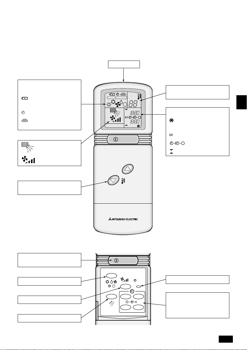
3. Name of Component
• Wireless Remote Controller
∗ The following example is f or explanatory purposes only and shows the operating section when all
the LCD displays are lit. It differs from the actual display. The LCD will remain dark while the
remote controller is not in operation.
Trancemitter Point this section to the Signal
Receiving Unit.
Operation mode
display .................Page 10
Battery
voltage low ............ Page 8
display .............Page 12
Transmission
mark .................... Page 10
Vane .........Page 11
Fan...........Page 11
Temperature ........Page 10
adjusting button
CHECK TEST RUN
NOT AVAILABLE
CHECK TEST RUN
NOT AVAILABLE
AM
PM
AM
PM
ON/OFF
TEMP.
AM
PM
AM
PM
Pre-set
temperature .........Page 10
˚C
GB
Current time........... Page 9
display
Timer time ........... Page 12
display..............Page 13
display .... Page 12
display ....... Pages 9, 12
˚C
Power ON/OFF
button .................. Page 10
MODE button....... Page 10
FAN button...........Page 11
VANE button ........Page 11
ON/OFF
MODE
VANE STOP START
FAN
CLOCK
MIN.
HR.
When the Cover is Open.
CLOCK button ........ Page 9
STOP, START (TIMER SET)
button.................... Page 12
HR. MIN. b utton.. Pages 9, 12
5
Page 5
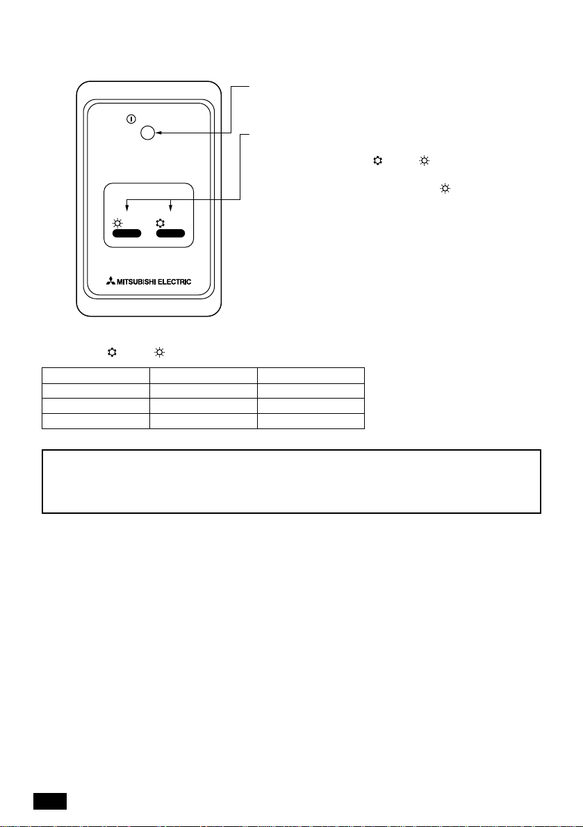
• Signal Receiving Unit (Sold separately)
HEAT
ON/OFF lamp (lit when unit is operating; unlit when unit is
not operating)
ON/OFF
Emergency operation
In cases where the remote control unit does not operate
properly , use either the
less remote control signal receiver to toggle the unit on or
off. On cooler only units, pushing the
the fan on and off.
HEAT COOL
COOL
or
HEAT
button on the wire-
button toggles
Pressing the
COOL
or
HEAT
button selects the following settings.
Operation mode COOL HEAT
Preset temperature 24 °C 24 °C
Fan speed High High
Air Direction Horizontal Down
Note:
The signals may not be received in rooms where inverter type fluorescent lamps are used. Consult
your dealer when re-purchasing fluorescent lamps.
6
Page 6

OPEN
1 2 43
ON
• Use two 24A size alkaline
batteries. Make sure you align
the battery polarities correctly.
•
Remove the batteries if you do
not expect to use the controller
for a long time.
After refilling batteries,
press the reset button.
Reset
4. Before Operation
4-1. Setting the DIP-Switch
It is necessary to set the DIP switches before using this remote control unit.
∗ The remote control unit will not operate properly unless the DIP switch settings are correct.
∗ Customers should not perform the settings themselves, but rather should request that the settings
been made during installation by qualified personnel.
DIP Switch Settings
1 Check the settings (fan speed, louver, etc.) of the indoor unit and the outdoor unit to which it is
connected.
2 Adjust the DIP switches on the back of the remote control unit as necessary.
(Refer to Table 1 and Figure 1)
Table 1
SW OFF ON Description
AUTO mode is not AUTO mode is
1
supported supported
SWING (vane) SWING (vane)
2
is not supported is supported
3 4-stage fan speed
2-stage fan speed
Set to OFF on units which unsupported adjustable vane.
Set to OFF on units which unsupported fan speed control.
–
4 COOL/HEAT unit COOL only unit Set to OFF when SW1 is set to ON.
Factory settings are all OFF.
Figure 1
ON
1 2 43
• Use two 24A size alkaline
Factory setting
(All OFF)
Rear view of original
remote controller
batteries. Make sure you align
the battery polarities correctly.
Remove the batteries if you do
•
not expect to use the controller
for a long time.
ON
1 2 43
OPEN
RESET button
Battery cover
3 After making the DIP switch settings, remove the battery cover and insert two batteries.
4 Using a ball point pen or similarly pointed object, push the reset button and replace the battery
cover.
5 Verify that the remote control unit operates properly. If
it does not, check the indoor and outdoor units, then
redo the DIP switch settings.
Figure 2
6 After verifying that the remote control unit operates
properly, attach the protectiv e plate over the dip s witch.
(Refer to Figure 2.)
7 The DIP switch setting is now set up properly.
Adhesive double
coated tape is
provided on the
back.
Plate
GB
7
Page 7

4-2. Inserting Batteries
1 Remove the battery cover and insert the bat-
teries.
finger and slide the cover to remove.
2 Replace the battery cover and press the reset
button.
Re-place the battery cover.Press the area marked “ ” with your
™ All the LCD displays will light up for 3 seconds when the reset button is pressed.
™ Be sure to press the reset button whenever the batteries are replaced.
™ The controller may malfunction if the reset button is not pressed after the batteries have been
replaced.
Batteries
™ The batteries have run out when the “ ” mark (battery voltage drop) appears, when the signals
cannot reach the receiver of the air-conditioner or when the LCD becomes weak. In these cases,
replace the batteries with new alkaline batteries (size AAA). (Make sure that both batteries are
replaced.)
™ Using manganese batteries will reduce the distance the signals can reach.
™ Do not use rechargeable batteries (Ni-Cd).
™ The life of alkaline batteries is approximately one year.
™ Remove the batteries if the remote controller will not be used for a long time.
Note:
Do not change the settings on the
adjusting switch and pair number
switch when the battery cover is removed. Doing so will disable control.
8
Adjusting
Nrm Set
switch
3
2
4
1
5
0
6
9
7
8
Wireless remote controller operating section
(When the battery cover is removed)
Pair number
switch
Page 8

4-3. Setting the Current Time
1. When using f or the first time, following replacement of batteries or pressing the reset b utton:
ON/OFF
MODE
VANE STOP START
FAN
CLOCK
MIN.
HR.
2. When changing the current time:
ON/OFF
MODE
VANE STOP START
FAN
CLOCK
MIN.
HR.
CHECK TEST RUN
AM
PM
AM
NOT AVAILABLE
All the LCD displays will light up for three seconds, then “AM 0:00
PM
ON/OFF
3 seconds
later
˚C
AM
NOT AVAILABLE
ON/OFF
” starts to blink. After “AM 0:00 ” starts blinking, carry out the
following procedure.
1. Press the HR. and MIN. buttons to adjust the time to current
time.
2. Press the CLOCK button. The current time will blink and the
“ ” display will disappear.
All the LCD displays will disappear in 10 seconds.
1. Press POWER ON/OFF button if
the LCD displays are not on.
2. Press the CLOCK button. Check
that “ ” is displayed.
˚C
3. Press the HR. and MIN. b uttons to
adjust the time to current time.
4. Press the CLOCK button to complete the setting.
∗ Even if the CLOCK button is not
pressed, “ ” will disappear in one
minute.
NOT AVAILABLE
PM
ON/OFF
GB
4-4. Installing the Remote Controller Holder
™ To place the wireless remote controller on a wall, the remote controller holder must be installed as
shown below.
Remote
controlle
holder
Wood screws
(4.1×16)
How to Place the Controller in the Holder
2
1 Slip the remote controller into the holder.
2 From that position, push the controller to-
1
wards the wall.
How to Remove the Controller from the
Holder
• Pull the upper part of the remote controller towards you.
9
Page 9

5. Operating Method
™ Each time signals are transmitted, the “ ” mark will appear.
™ When the signals are received by the air-conditioner, a sound confirming reception will be heard.
Transmit again if no such sound is heard.
5-1. Starting Operation
™ Once the operation conditions are set, the same operations can be repeated just by pressing the
POWER ON/OFF.
ON/OFF
MODE
VANE STOP START
FAN
CLOCK
MIN.
HR.
1. Press the POWER ON/OFF button.
Each time POWER ON/OFF is pressed, the operation will be
switched between ON and OFF.
∗ No LCD displays will light up while the controller is turned off.
2. Press the MODE button.
Each time the MODE button is pressed, the operation mode will
switch as shown below.
→ COOL → DRY → <AUTO> → FAN → <HEAT>
Note:
There are some indoor unit models which do not support AUTO or HEAT mode. In these cases the
operation of the air-conditioner and the display of the remote control may differ.
5-2. Changing the Pre-set Temperature
ON/OFF
TEMP.
If the LCD displays are not on, press the POWER ON/OFF
button.
1. To increase the pre-set temperature.
Press the button.
2. To reduce the pre-set temperature.
Press the button.
™ Each time the or button is pressed, the pre-set tem-
perature changes in steps of 1 degrees Celsius.
10
Settable room temperature range
COOL, DRY 19 °C to 30 °C
HEAT 17 °C to 28 °C
AUTO 19 °C to 28 °C
FAN No temperature setting can be made.
Page 10

5-3. Changing the Fan Speed and Direction
ON/OFF
MODE
VANE STOP START
FAN
HR.
CLOCK
MIN.
If the LCD displays are not on, press the POWER ON/OFF
button.
1. To Change the Fan Speed
™ Press the FAN button and the fan speed will change.
For 4-stage speed:
GB
For 2-stage speed:
2. To Change the Direction
™ Press the VANE button and the flap (v ane) will move v ertically .
For Swing:
For no swing:
Note:
There are some indoor unit models which do not feature fan speed or swing. In these cases the
operation of the air-conditioner and the display of the remote control may differ.
11
Page 11

5-4. Setting the Timer
Stop Time Setting
The air-conditioner stops operation when the pre-set time is reached.
(The time can be set in steps of ten minutes.)
e.g. To make the operation stop at 6:00 pm.
1. If the LCD displays are not on, press the POWER ON/OFF but-
2. Press the STOP button (TIMER SET).
3. Press the HR. and MIN. buttons.
When the time is set, the Stop Timer setting is completed.
Start Timer Setting
The air-conditioner stops operation when the pre-set time is reached.
e.g. To cause the operation to start at 9:00 am.
1. If the LCD displays are not on, press the POWER ON/OFF but-
2. Press the START button (TIMER SET).
3. Press the HR. and MIN. buttons.
When the time is set, the Start Timer setting is completed.
PM
NOT AVAILABLE
ON/OFF
MODE
FAN
VANE STOP START
MIN.
HR.
NOT AVAILABLE
MODE
AM
ON/OFF
CLOCK
FAN
VANE STOP START
MIN.
HR.
˚C
CLOCK
˚C
ton.
™ Check that “ ” and “ ” are displayed.
™ To cancel, press the STOP button once again.
™ Adjust the displayed time to 6:00 pm.
™ When “ ” is not displayed, time setting cannot be carried out.
In this case, press the STOP button again to cause “ ” to be
displayed.
™ When the Stop Timer is set, the set time will be displayed instead
of the current time.
During the setting of Stop Timer , “ ” will be display ed but “ ” will
not be displayed.
ton.
™ Check that “ ” and “ ” are displayed.
™ To cancel, press the START button once again.
™ Adjust the displayed time to 9:00 am.
™ When “ ” is not displayed, time setting cannot be done.
In that case, press the START button again to cause “ ” to be
displayed.
™ When the Start Timer is set, the set time will be displayed instead
of the current time.
During the setting of Start Timer “ ” will be displayed but “ ” will
not be displayed.
Note:
™ The operation mode, pre-set temperature and the fan speed will be displayed during Start Timer
operation, but the air-condition will not start until the pre-set start time is reached.
™ The blowout direction cannot be changed once the Start Timer setting is completed.
12
Page 12

Program Operation
™ Program operation can be used by carrying out Star t Timer Setting and Stop Timer Setting one
after the other.
™ In cases where the pre-set times for Stop Timer and Start Timer are the same, program operation
can be used by pressing the STOP and START (TIMER SET) buttons one after the other.
™ The timers will come into effect in the order of the pre-set times.
(The “↑” and “↓” indicate the order in which Start Timer and Stop Timer are activated.)
e.g. 1) When current time is 8:00 pm:
To make the air-conditioner stop at 11:00 pm
and start at 6:00 am the following morning.
1
AM
PM
AM
PM
ON ON
OFF
11
8
6
e.g. 2) When current time is 11:00 am:
To make the air-conditioner start at 5:00 pm
and stop at 9:00 am the following morning.
1
AM
PM
AM
PM
OFF OFF
11
ON
9
5
Note:
™ Timer times can be set in steps of ten minutes.
™ If the POWER ON/OFF button is pressed during timer operation, the timers will be canceled.
™ If the air conditioner is tur ned On or Off after the timer operation ends, the operation mode will
switch automatically back to continuous operation mode. The air-conditioner will start in the
continuous mode when it is turned on next time.
GB
13
Page 13

6. Test Run
A
B
CHECK TEST RUN
NOT AVAILABLE
AM
PM
AM
PM
ON/OFF
˚C
8
CHECK TEST RUN
NOT AVAILABLE
AM
PM
AM
PM
ON/OFF
˚C
45
7
MODE
VANE STOP START
FAN
CLOCK
6
After refiling batteries.
Press the reset button.
MIN.
HR.
3
Nrm Set
2
Reset
3
2
4
1
5
0
6
9
7
8
9
1 Turn on the main power to the unit.
2 Set the Nrm/Set selector switch (on the back of the controller) to «Set».
A The
CHECK
3 Press the
TEST RUN
B
and current operation mode are displayed.
4 Press the MODE ( ) button to activate F AN mode, then check whether air is blown out
from the unit.
5 Press the MODE ( ) button to activate COOL mode, then check whether cool air is
blown out from the unit.
6 Press the FAN button and check whether strong air is blown out from the unit.
7 Press the VANE button and check whether the auto vane operates properly.
8 Press the ON/OFF button to stop the test run.
9 After test run is complete, set the Nrm/Set selector switch to «Nrm».
and
MIN.
TEST RUN
button.
begin to blink.
Note:
Point the remote controller toward the receiver while following steps 3 though 8.
14
Page 14

Contents
Page
1. Safety Precautions................................................................................ 3
2. Checking the Contents of the Package................................................. 4
3. Name of Component ............................................................................ 5
4. Before Operation .................................................................................. 7
4-1. Setting the DIP-Switch.................................................................. 7
4-2. Inserting Batteries ........................................................................ 8
4-3. Setting the Current Time............................................................... 9
4-4. Installing the Remote Controller Holder........................................ 9
5. Operating Method ............................................................................... 10
5-1. Starting Operation ...................................................................... 10
5-2. Changing the Pre-set Temperature............................................. 10
5-3. Changing the Fan Speed and Direction...................................... 11
5-4. Setting the Timer ........................................................................ 12
6. Test Run ............................................................................................. 14
7. Centrally Controlled ............................................................................ 15
8. Troubleshooting .................................................................................. 15
9. Specifications ..................................................................................... 15
2
Page 15

7. Centrally Controlled
1. In cases where local operation by wireless remote controller is prohibited.
™ When remote operation is prohibited due to centralized control, the prohibited operations cannot
be performed using a wireless remote controller.
• There are 3 types of remote operation that are prohibited, starting and stopping, operating
mode and temperature setting.
2. In cases where wireless remote controller are operated during Centrally Controlled.
• Operations other than the prohibited items are enabled.
™ Signal Receiving Unit will respond as follows.
• Unit will beep twice.
• ON/OFF lamp will flash three times at 0.25 second intervals if the unit is ON or two times if it
is OFF.
Note:
In this case the operation of the air-conditioner and the display of the remote control may differ.
8. Troubleshooting
<When the operation lamp of the Signal Receiving Unit is blinking>
This means that an abnormality has occurred with the air conditioner. In this case , turn the power off and
consult your dealer. Do not try to repair by yourself.
9. Specifications
Item Specification
Power supply voltage 3 VDC (two size-AAA alkaline batteries)
Operating environment Temp. 0 to 40 °C, Humidity 30 to 90 % RH (No condensation allowed)
Weight 0.09 kg (without batteries)
Dimensions 153 (H) × 57 (W) × 21 (D)
Installation Wall installation using remote controller holder
Time display 12-hour time display (Current time, Stop timer time, Start timer time)
Time setting Times can be set in steps of 10 minutes.
Display method Digital LCD
Clock accuracy ±50 seconds per month (at 25 °C)
GB
15
Page 16

This product is designed and intended for use in a residential, commercial or light-industrial environment.
The product at hand is based on the following EU regulations:
• Electromagnetic Compatibility Directive 89/336/EEC
HEAD OFFICE MITSUBISHI DENKI BLDG MARUNOUCHI TOKYO 100-8310 TELEX J24532 CABLE MELCO TOKYO
???
WT02966X01
 Loading...