

Page 1
1
WT04107X01-NZ
GB
CITY MULTI Control System
Remote Controller PAR-F27MEA
PAR-F20MAA
Instruction Book
WARNING
This symbol denotes what could lead to serious injury or death if you misuse the Controller.
CAUTION
This symbol denotes what could lead to a personal injury or damage to your property if you misuse the Controller
1 Safety Precautions
The following two symbols are used to dangers that may be caused by incorrect use and their degree:
Thank you for purchasing a Mitsubishi CITY MULTI system.
To use your CITY MULTI system correctly and safely, please read this book before use.
After reading this book, keep it and the installation manual in a place where the final user can see them at anytime.
When the end user has changed, forward this book and the instruction manual to the new final user.
Do not try to install or move this system by yourself. (Safety and functions cannot be ensured)
Do not use in any special environment.
Using in any place exposed to oil (including machine oil), steam and sulfuric
gas may deteriorate the performance significantly or give damage to the component parts.
Do not press any control button using a sharp object.
Doing so may cause an electric shock or a malfunction.
Operate the controller within the specified temperature range.
Observe the specified temperature range when operating the controller. If
the controller is used outside the specified temperature range, it may cause
serious damage. Be sure to check the operation temperature range in the
operation manual.
Do not pull or twist the transmission line.
It may cause a fire or malfunction.
Do not dismantle the unit.
It is dangerous to touch the internal circuit board. It may cause a fire or malfunction.
Do not install in any place exposed to flammable gas leakage.
Flammable gases accumulated around the body of the controller may cause
an explosion.
Do not wash with water.
Doing so may cause an electric shock or a malfunction.
Do not touch any control button with your wet hands.
Doing so may cause an electric shock or a malfunction.
Do not use the controller for special applications.
This product is designed for use with the CITY MULTI CONTROL SYSTEM.
Do not use the system for other air condition management operation or applications. It may cause malfunctions.
Do not apply insecticide or flammable sprays to the controller.
Do not place flammable spray near the controller and make sure it does not
blow directly on the controller as this may cause in fire.
Do not clean the unit using benzene, thinner or other chemicals.
It may cause discoloration or other damage. If the unit should become particularly dir ty, apply a mild cleaner that has been diluted with water to a soft
cloth and wipe the unit clean. Be sure to wipe away any residual moisture
with a dry cloth.
WARNING
Do not move and re-install the Controller yourself.
Any deficiency caused by installation may result in an electric shock or fire.
Ask your distributor or special vendor for moving and installation.
To dispose of this product, consult your dealer.
Never modify or repair the Controller by yourself.
Any deficiency caused by your modification or repair may result in an electric
shock or fire.
Consult with your dealer about repairs.
Stop the operation immediately and notify the your dealer if an error
code is displayed or malfunction occurs.
Fire or damage may cause it the controller is operated in this condition.
Ask your dealer or technical representative to install the unit.
Any deficiency caused by your own installation may result in an electric shock
or fire.
Securely install in a place which can withstand the weight of the controller.
If it is not enough, the controller may drop and cause an injury.
Make sure that the controller is connected to a rated power supply.
If the controller is not connected to a rated power supply, it may cause a fire
or damage to the controller.
Stop the operation if any malfunction occurs.
If malfunction occurs (burning smell, etc.) stop the operation and turn off the
power supply. Contact the your dealer or technical representative immediate.
If the controller continues to operate after a malfunction occurs, this may
cause damage, electric shock or fire.
CAUTION
Page 2
2
CENTRALLY CONTROLLED
DAILY
AUTO OFF
REMAINDER
CLOCK
ON
OFF
˚C
FILTER
˚C
1Hr.
NOT AVAILABLE
STAND BY
DEFROST
PAR-F27MEA
ON/OFF
CENTRALLY CONTROLLED
DAILY
AUTO OFF
REMAINDER
CLOCK
ON OFF
˚C
CHECK MODE
FILTER
TEST RUN
LIMIT TEMP.
˚C
1Hr.
NOT AVAILABLE
STAND BY
DEFROST
FILTER
CHECK TEST
TEMP.
TIMER SET
CLOCK→ON→OFF
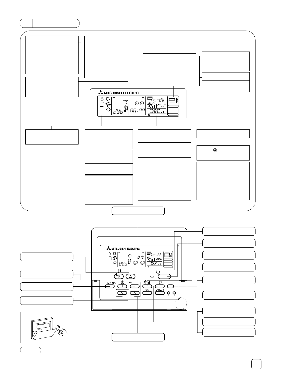
“CENTRALLY CON-
TROLLED” display
Displayed when air conditioner
operation is prohibitted by a central controller, etc. When the remote controller buttons are
locked, this display flashes.
“Current/Starting/
Ending/REMAINING
time” display
Displays the current time and
timer set times.
When the timer is operating, displays the normal time and the
stating, ending, or remaining
time.
“TIMER” “DAILY”
“AUTO OFF” Display
Displays the timer mode when
the timer is set.
There are three timers modes:
1 day timer, daily timer, and auto
off timer. One of these modes
can be selected.
“Airflow” display
Displays the outlet air direction.
“Louver” display
Displays operation of the
swing louver. It is not displayed when the louver is
stopped.
“ ” display
Displayed while the power is on.
“FILTER” display
Indicates that it is time to
clean the filter.
“Ventilation” display
Displayed during fan operation.
“NOT AVAILABLE”
display
When the button of a function
that is not installed at the indoor
unit was pressed, this display
flashes simultaneously with the
corresponding function display.
“Operation mode”
Displays the operation mode.
“Set temperature”
display
Displays the set temperature.
(For description purposes, all the
displays are assumed to be on.)
“Set effective for 1 hr.”
display
Displayed when low downward
is selected at cooling and electronics dry operation.
(Differs with the model.)
After one hour, the display goes
off, and swing also switches.
“Wind speed”
display
Displays the selected wind
speed.
DISPLAY SECTION
OPERATION SECTION
ON/OFF lamp
ON/OFF button
FILTER button
Wind speed button
CHECK button
(Normally not used)
TEST RUN button
(Normally not used)
Airflow button
Louver button
Ventilation button
Built-in temperature sensor position
When an operation button is pressed, if the indoor unit does not have that function, “NOT AVAILABLE” flashes.
When one remote controller controls multiple indoor units, if the master indoor unit has the selected function, this message is not displayed.
Open the door.
NOTE
2 Part Names
Timer selection button
Mode selection button
TEMP. buttons
(▼) Lower (▲) Raise
(▼) Return (▲) Ahead
“Room temperature”
display
Displays the intake temperature
while the air conditioner is operating.
“Senser” display
Displayed when the remote
controller sensor is used.
Time selection buttons
Page 3
3
PAR-F27MEA
ON/OFF
˚C
˚C
FILTER
CHECK TEST
TEMP.
TIMER SET
CLOCK→ON→OFF
1
1
4
2
3
2
3
1
7
6
5
1
7
5
6
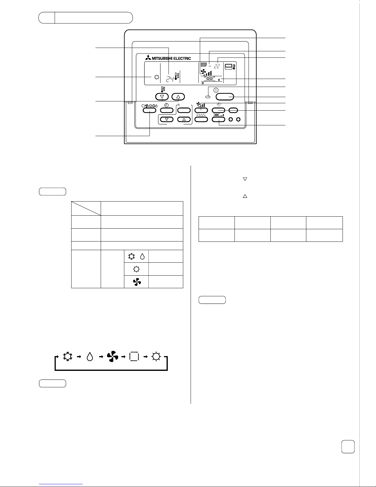
(1) On/off and operation mode selection and room temperature adjustment
When starting operation
■ Press the [ON/OFF] button 1.
• The ON lamp 1 and display light.
NOTE
The restarting operation contents are shown below.
When you want to change the set temperature
<When you want to lower the room temperature>
■ Press the [TEMP. (
)] button 3.
<When you want to raise the room temperature>
■ Press the [TEMP. (
)] button 3.
• The set temperature changes 1 °C each time the button is pressed.
The set temperature is displayed at 3.
• The following specified temperatures can be set:
Room temperature display
During operation, the intake temperature is displayed at 4.
- The display range is 8 to 39 °C. When this range is exceeded, the
room temperature display flashes at 8 °C or 39 °C.
- When multiple indoor units are controlled, the contents of the master
indoor unit are displayed on the remote controller.
- The room temperature sensor position can be selected from “INDOOR
UNIT” and “REMOTE CONTROLLER”.
The initial setting is “INDOOR UNIT”. When you want to change the
room temperature sensor position to “REMOTE CONTROLLER”, consult your dealer.
- When “no room temperature display” was selected by remote controller function selection, the room temperature is not displayed.
NOTES
Cool/dry
operation
Heat operation Auto operation Fan
19(14) to 30 °C 17 to 28 °C 19 to 28 °C
The auto and heating functions may not be installed, depending on the
outdoor unit model.
NOTE
Remote controller settings
When stopping operation
■ Press the [ON/OFF] button 1.
• The ON lamp 1 and display go off.
When selecting the operation mode
■ Press the [Mode selection] button 2 while the air conditioner is oper-
ating.
• The setting is switched each time the button is pressed.
The operation mode is displayed at 2.
Operation
mode
Horizontal
outlet
Temperature
setting
Wind speed
Operation
mode
Last set wind speed
Last set temperature
Last operation mode
Last setting
Horizontal
outlet
Cannot be set.
3 How to Operate
Airflow
Page 4

4
(2) Wind speed and wind direction adjustment and fan operation
When you want to change the wind direction
■ While the air conditioner is operating, press the [Airflow] button 6.
• Each time the button is pressed, the setting changes as shown below.
The wind direction is displayed at 6.
• The following wind directions can be selected:
- Depending on the indoor unit and fan model, the indoor unit may operate even when only the fan was operated.
- When “NOT AVAILABLE” is displayed when the [Ventilation] button 7 was pressed, the fan is not interlocked.
- In cases such as the following, the liquid crystal display and unit wind
speed are different:
1. When “HEAT STAND BY” or “DEFROSTING” is displayed.
2. Immediately after heating operation (while waiting for mode selection)
3. When the room temperature is higher than the set temperature in the
heating mode.
4. Dry operation
- For 3-speed models, a central controller wind speed display and the
remote controller wind speed display may be different.
NOTES
When you want to change the wind speed
■ While the air conditioner is operating, press the [Wind speed] button
5.
• Each time the button is pressed, the setting changes as shown below.
The wind speed is displayed at 5.
• The following wind speeds can be selected:
Wind speed
4-speed model
3-speed model
2-speed model
Remote controller display
* The wind speeds that can be selected depend on the model.
- In cases such as the following, the liquid crystal display and unit airflow
may be different.
1. When “HEAT STANDBY”or “DEFROSTING” is displayed
2. Immediately after heating operation (Waiting for mode selection)
3. When the room temperature is higher than the set temperature in
the HEAT mode
NOTE
* After one hour, automatically returns to the horizontal position.
* During swing operation, remote controller display and airflow vane po-
sition cannot be synchronized.
* There may not be an airflow function, depending on the model.
(3) How to operate the timer
There are the following three timer modes. Select one of them.
1) 1 day timer mode
In this mode, the ON and OFF timers (10-minute units) can each be set to one time within 24 hours.
This mode has the following three setting methods:
· ON timer operation : Timer only star ts the air conditioner.
· OFF timer operation : Timer only stops the air conditioner.
· ON/OFF timer operation: Timer both starts and stops the air conditioner.
2) Daily timer mode
Operation of this mode is the same as that of the 1 day timer mode. However, timer operation can be set to the same time each day in accordance
with the set ON/OFF timer time. (ON/OFF timer each 1 time/daily)
3) Auto off timer mode
The OFF timer can be easily set in 30-minute units. (30 minutes to 4 hours range) When the remaining time reaches 0:00, the air conditioner stops.
When the Auto off timer mode is selected, the next time the air conditioner is started, the OFF timer operates automatically so that the timer can be
used to turn off the air conditioner if you should forget.
When ON/OFF operation from the central controller, etc. was restricted when timer operation was set, the set ON/OFF timer is not executed. After the
restriction is removed, timer operation is performed at the ON/OFF time.
When ON/OFF operation was restricted during AUTO OFF timer operation, the remaining time at the point operation was restricted is memorized and the
air conditioner is stopped after the memorized remaining time from the time the restriction was removed.
NOTE
Setting 4
(horizontal 85˚)
Swing
Setting 1
(horizontal 0˚)
Setting 2
(horizontal 45˚)
Setting 3
(horizontal 60˚)
Display
Cool
Heat/fan
Dry
Not
settable
Airflow setting
when operation
mode was changed
Downward
85˚
Swing
Swing
* Horizontal after 1 hour
Cool
Dry
Fan
operation
Heating
operation
–––
Downward
60˚
Downward
45˚
Horizontal
outlet
Downward 85˚Downward 60˚Downward 45˚
Horizontal outlet
Operation
mode
Wind
Speed
Fan operation
<When operating fan interlocked with indoor unit>
When the indoor unit is operated, the fan is automatically operated also.
Fan operation is displayed at 7.
<When operating fan only while indoor unit stopped>
■ While the air conditioner is stopped, press the [Ventilation] button 7.
The ON/OFF lamp 1 lights and fan operation is displayed at 7.
<When you want to change the fan wind speed>
■ Press the [Ventilation] button 7.
Each time the button is pressed, the wind speed is changed as shown
below.
(Low) (Mid1) (Mid2) (High)
(Mid1) (Mid2) (High)
(Mid1) (High)
High/Mid1
Mid2/Low
High
Mid1/Mid2/Low
Off
(no display)
Remote controller display
NOTES
Page 5

5
PAR-F27MEA
ON/OFF
OFF
˚C
˚C
FILTER
CHECK TEST
TEMP.
TIMER SET
1
3
2
CLOCK→ON→OFF
ON
OFF
DAILY
REMAINDER
AUTO OFF
← 1 day timer mode
8 A.M. operation start
← Daily timer mode
5 P.M. daily operation stop
← Auto off timer mode
Operation stop when 2 hours remain
When setting the current time
■ Press the [Time selection] button 1 and display “CLOCK”.
• Each time the button is pressed, the time is switched as shown below.
■ Each time the [Time selection (
)] button
2 is pressed, the time advances one minute and each time the [Time selection (
)] button 2 is pressed, the
time returns one minute.
• When the button is held down, the time advances or returns continuously. The time changes in 1 minute units → 10 minutes units → 1 hour units order.
• About 10 seconds after the end of setting, the remote controller display goes off.
* When a power failure occurs, the current time is reset. Reset the clock.
When performing ON timer operation (1 day timer mode/daily timer mode)
■ Press the [Time selection] button 1 and check “Current time (CLOCK)” and display “Starting time (ON)”.
■ Set the ON time by pressing the [Time selection (
) or ( )] button
2.
■ Set the OFF time to “-- : --” display.
• “-- : --” display is displayed between 23 : 50 and 0 : 00.
■ Press the [Timer selection] button 3 and set the display to “
” (1 day timer mode) or “ ” + “DAILY” (daily timer mode).
• Each time the button is pressed, the timer mode is switched as shown below.
No display
[Timer setting display example]
• 1 day timer mode
REMAINDERCLOCK
ON
OFF
When performing OFF timer operation (1 day timer mode/daily timer mode)
■ Press the [Time selection] button 1 and check “Current time (CLOCK)” and set the display to “Ending time (
OFF
)”.
■ Set the OFF time by pressing the [Time selection (
) or ( )] button 2.
■ Set the ON time to “-- : --” display.
■ Press the [Timer selection] button 3 and set the display to “ ” (1 day timer mode) or “ ” + “DAILY” (daily timer mode).
DAILY
AUTO OFF
(1 day timer mode) (Daily timer mode) (Auto off timer mode)
* The Auto off timer mode is skipped at the OFF window.
Off
DAILY
AUTO OFF
(1 day timer mode) (Daily timer mode) (Auto off timer mode)
* The Auto off timer mode is skipped at the OFF window.
Off
• Daily timer mode
• Auto off timer mode
When performing ON/OFF timer operation (1 day timer mode/daily timer mode)
■ See the setting when performing ON timer and OFF timer operation and check “Current time (CLOCK)” and set both the ON time and OFF time.
■ Press the [Timer selection] button 3 and set the display to “
” (1 day timer mode) or “ ” + “DAILY” (daily timer mode).
When performing AUTO OFF timer operation (AUTO OFF timer mode)
■ The Auto off timer can only be set while the air conditioner is operating.
■ Press the [Timer selection] button 3 and set the display to“
” + “AUTO OFF” (Auto off timer mode).
■ Set the desired remaining time by pressing the [Time selection (
) or ( )] button
2. (30 minutes units, 30 minutes to 4 hours)
After remaining time setting, the timer automatically starts.
When releasing timer operation
■ Press the [Timer selection] button 3 and turn off the “TIMER” display.
Page 6

6
CENTRALLY CONTROLLED
˚C
˚C
˚C
˚C
˚C
FILTER
˚C
(4) Other displays and flashing
– “CENTRALLY CONTROLLED” display –
May also be individually restricted.
NOTE
• Displayed when operation is controlled by central controller, etc.
Restricted operations are shown below.
· ON/OFF (including timer operation)
· Operation mode
· Set temperature
- When two or more different types of indoor unit are controlled, the cleaning period differs with the type of filter. When the master unit cleaning
period arrives, “FILTER” is displayed. When the filter display goes off,
the cumulative time is reset.
- “FILTER” indicates the cleaning period when the air conditioner was
used under general indoor air conditions by criteria time. Since the degree of dirtiness depends on the environmental conditions, clean the
filter accordingly.
- The filter cleaning period cumulative time differs with the model.
NOTES
• Indicates that the filter needs cleaning.
Clean the filter.
• When resetting “FILTER” display
When the [FILTER] button is pressed two times successively after
cleaning the filter, the display goes off and is reset.
– “FILTER” flashing –
– “Operation mode” flashing –
<When flashes continuously>
• Displayed when another indoor unit connected to the outdoor unit is
already operating in a different operation mode.
Match with the operation mode of the other indoor unit.
<When mode switched after display flashes>
• Displayed when operation mode is restricted for each season by central controller, etc.
Use another operation mode.
ERROR CORD
CHECK
ON/OFF
˚C
˚C
ERROR CORD
ON/OFF
– “ERROR CODE” flashing –
• When only “ERROR CODE” flashes
(ON lamp remains a steady light)
The air conditioner continues to operate, but there is the possibility of
trouble occurring.
Jot down the error code and consult your dealer.
• When both the “ON” lamp and “ERROR CODE” flash, trouble occurred in the air conditioner and the air conditioner stops.
Jot down the unit number and error code and turn off the air conditioner power and consult your dealer.
ON lamp (flashed)
unit number
(5) How to select the remote controller functions
In the remote controller function selection mode, three functions can be selected and changed. Select and change them as required.
1) Operation mode display selection mode
(Automatic mode cool/heat display selection)
When the AUTO operation mode was set by remote controller, the indoor unit is judged from the room temperature and the cooling or heating
operation is performed automatically. In this case, “AUTO” “COOL” or “AUTO” “HEAT” is displayed at the remote controller. However, “AUTO” can be
displayed alone without the “COOL” or “HEAT” display.
2) Room temperature display selection mode
(Room temperature display/no display selection)
Normally, the intake temperature is displayed at the remote controller, but setting can be performed so that it is not displayed.
[Time selection (
) or ( )] button
• When “ON” was selected, “AUTO” “COOL” or “AUTO” “HEAT” is displayed during AUTO mode operation.
• When “OFF” was selected, only “AUTO” is displayed during AUTO mode operation.
OPERATION MODE DISPLAY SELECTION MODE (When you want to change the AUTO mode display)
• This setting is unavailable when the controller is connected to an air conditioner without AUTO mode.
• “AUTO” “COOL/HEAT” flashes and “ON” or “OFF” lights. Each time the [Time selection (
) or ( )] button
4 is pressed in this state, the “ON” and
“OFF” display is switched.
Page 7

7
3. At the end of selection of each function, release the remote controller function selection mode and display the OFF window by pressing the [CHECK]
and [Mode selection] buttons 1 at the same time for two seconds.
4 Specifications
Item
Size
Weight
Power requirement
Power consumption
Environmental conditions
Material
Contents
120 (H) × 130 (W) × 19 (D) mm
0.2 kg
DC30 V Power supplied from M-NET transmission line (Normally, power is received from the outdoor unit over
the indoor/outdoor unit M-NET transmission line.)
0.5 W
Temperature 0 to 40 °C, humidity 30 to 90 % RH (No condensation)
PS
ROOM TEMPERATURE DISPLAY SELECTION MODE (When you want to change room temperature display/no display)
• “88 °C” flashes at the room temperature display and “ON” or “OFF” lights. Each time the [Time selection (
) or ( )] button
4 is pressed in this
state, the “ON” and “OFF” display is switched.
• When “ON” was selected, the room temperature is continuously displayed in the ON window.
• When “OFF” was selected, the room temperature is not displayed in the ON window.
˚C
˚C
[Time selection (
) or ( )] button
 Loading...