

Mitsubishi Electric PAR-CT01MAA-SB, PAR-CT01MAR-PB, PAR-CT01MAA-PB, PAR-CT01MAA-S, PAR-CT01MAR-SB Installation Manual
Page 1
– 1 –
GB
This installation manual describes how to install the MA Touch Remote Controller for use with
Mitsubishi Building Air Conditioning System, direct expansion type CITY MULTI air conditioner indoor
units (“-A” type and later), and Mitsubishi Mr. SLIM packaged air conditioners.
Please be sure to read this installation manual and the files on the CD-ROM that is supplied with the
Touch Remote Controller before proceeding with the installation. Failure to follow the instructions may
result in equipment damage.
For information not contained in this booklet, please refer to the files on the CD-ROM that is supplied
with the Touch Remote Controller. If the files are not readable, please contact your dealer.
For information on how to wire and install the air conditioning units, refer to the installation manual.
After the installation, hand over this manual to users.
• Thoroughly read the following safety precautions prior to installation.
• Observe these precautions carefully to ensure safety.
• After reading this manual, pass it on to the end user to retain for future reference.
• Keep this manual for future reference and refer to it as necessary. This manual should be made
available to those who repair or relocate the controller. Make sure that the manual is forwarded to
future end users.
1 Safety Precautions
WARNING
Indicates a risk of death or serious injury.
CAUTION
Indicates a risk of serious injury or structural damage.
All electric work must be performed by qualified personnel.
CITY MULTI Control System
and Mitsubishi Mr. SLIM Air Conditioners
MA Touch Remote Controller
PAR-CT01MAA-PB
PAR-CT01MAA-SB
PAR-CT01MAA-S
PAR-CT01MAR-PB
PAR-CT01MAR-SB
Installation Manual
WT08580X01
GB
For distribution to dealers and contractors
FESIPRGRTRSWDNLRUCZHGPO
<ORIGINAL>
DK
Page 2
– 2 –
GB
WARNING
CAUTION
WARNING
CAUTION
General precautions
Precautions during installation
Do not install the unit in a place where large amounts of
oil, steam, organic solvents, or corrosive gases, such
as sulfuric gas, are present or where acidic/alkaline
solutions or sprays are used frequently. These
substances can compromise the performance of the
unit or cause certain components of the unit to corrode,
which can result in electric shock, malfunctions,
smoke, or fire.
To reduce the risk of shorting, current leakage, electric
shock, malfunctions, smoke, or fire, do not wash the
controller with water or any other liquid.
To reduce the risk of electric shock, malfunctions,
smoke or fire, do not operate the switches/buttons or
touch other electrical parts with wet hands.
To reduce the risk of injury or electric shock, stop the
operation and switch off the power supply before
cleaning, maintaining, or inspecting the controller.
To reduce the risk of injury or electric shock, before
spraying a chemical around the controller, stop the
operation and cover the controller.
To reduce the risk of injury, keep children away while
installing, inspecting, or repairing the unit.
Properly install all required covers to keep moisture
and dust out of the controller. Dust accumulation and
water can cause electric shock, smoke, or fire.
To reduce the risk of electric shock or malfunctions, do
not touch the touch panel, switches, or buttons with a
pointy or sharp object.
To reduce the risk of damage to the controller, do not
directly spray insecticide or other flammable sprays on
the controller.
To reduce the risk of injury and electric shock, avoid
contact with sharp edges of certain parts.
To reduce the risk of injury, wear protective gear when
working on the controller.
Consult your dealer for the proper disposal of the
controller.
To avoid injury from broken glass, do not apply
excessive force on the glass parts.
To reduce the risk of fire or explosion, do not place
flammable materials or use flammable sprays around
the controller.
Do not install the unit where there is a risk of leaking
flammable gas.
If flammable gas accumulates around the unit, it may
ignite and cause a fire or explosion.
Take appropriate safety measures against earthquakes
to prevent the controller from causing injury.
Properly dispose of the packing materials. Plastic bags
pose suffocation hazard to children.
To prevent injury, install the controller on a flat surface
strong enough to support its weight.
To reduce the risk of shorting, current leakage, electric
shock, malfunctions, smoke, or fire, do not install the
controller in a place exposed to water or in a
condensing environment.
Controller must be installed by qualified personnel
according to the instructions detailed in the Installation
Manual.
Improper installation may result in electric shock or fire.
Install the top case into the bottom case until it clicks.
When attaching the cover and the top casing to the
bottom casing, push it until it they click into place. If
they are not properly locked into place, they may fall,
causing personal injury, controller damage, or
malfunctions.
Page 3
– 3 –
GB
WARNING
CAUTION
WARNING
CAUTION
Precautions during wiring
Precautions for moving or repairing the controller
To reduce the risk of damage to the controller,
malfunctions, smoke, or fire, do not connect the power
cable to the signal terminal block.
Properly secure the cables in place and provide
adequate slack in the cables so as not to stress the
terminals. Improperly connected cables may break,
overheat, and cause smoke or fire.
To reduce the risk of injury or electric shock, switch off
the main power before performing electrical work.
All electric work must be performed by a qualified
electrician according to the local regulations,
standards, and the instructions detailed in the
Installation Manual.
To reduce the risk of electric shock, install a breaker
and a residual current circuit breaker on the power
supply.
To reduce the risk of electric shock, smoke, or fire,
install a breaker for each controller.
Use properly rated breakers and fuses (breaker, local
switch <switch + fuse>, no-fuse breaker).
Breaker with a breaking capacity greater than the
specified capacity may cause electric shock,
malfunctions, smoke, or fire.
To reduce the risk of current leakage, overheating,
smoke, or fire, use properly rated cables with adequate
current carrying capacity.
Proper grounding must be provided by a licensed
electrician.
Do not connect the grounding wire to a gas pipe, water
pipe, lightning rod, or telephone wire.
Improper grounding may result in electric shock,
smoke, fire, or malfunction due to electrical noise
interference.
To reduce the risk of electric shock, shorting, or
malfunctions, keep wire pieces and sheath shavings
out of the terminal block.
To reduce the risk of shorting, current leakage, electric
shock, or malfunctions, keep the cables out of contact
with controller edges.
Securely seal the cable access holes with putty to
prevent condensation, water, and insects from entering
and causing electric shock, malfunctions, or fire. Water
infiltration and condensation formed inside the unit may
damage the circuit board.
The controller should be repaired or moved only by
qualified personnel.
Do not disassemble or modify the controller.
Improper installation or repair may cause injury, electric
shock, or fire.
To reduce the risk of electric shock, shorting, or
malfunctions, keep wire pieces and sheath shavings
out of the terminal block.
Page 4
– 4 –
GB
Additional precautions
To avoid damage to the unit, use appropriate tools to
install, inspect, or repair the unit.
This controller is designed for exclusive use with the
Building Management System by Mitsubishi Electric.
The use of this controller for with other systems or for
other purposes may cause malfunctions.
To avoid discoloration, do not use benzene, thinner, or
chemical rag to clean the controller.
To clean the controller, wipe with a soft cloth soaked in
water with mild detergent, wipe off the detergent with a
wet cloth, and wipe off water with a dry cloth.
To avoid damage to the controller, provide protection
against static electricity.
Take appropriate measures against electrical noise
interference when installing the air conditioners in
hospitals or facilities with radio communication
capabilities.
Inverter, high-frequency medical, or wireless
communication equipment as well as power
generators may cause the air conditioning system to
malfunction. Air conditioning system may also
adversely affect the operation of these types of
equipment by creating electrical noise.
To avoid malfunctions, do not bundle power cables and
signal cables together, or place them in the same
metallic conduit.
Leave the circuit board and its protective film on the
case.
To avoid damage to the controller, do not overtighten
the screws.
Use a flat-head screwdriver with a blade width of 3-5
mm (1/8-7/32 inch).
Do not turn the flat-head screwdriver with fitting it in the
latch strongly.
To avoid deformation and malfunction, do not install
the remote controller in direct sunlight or where the
ambient temperature may exceed 40ºC (104ºF) or
drop below 0ºC (32ºF).
Do not install the controller on the control panel door.
Vibrations or shocks to the controller may damage the
controller or cause the controller to fall.
Secure the cable with a clamp.
Do not use solderless terminals to connect cables to
the terminal block.
Solderless terminals may come in contact with the
circuit board and cause malfunctions or damage the
controller cover.
After connecting the connector, install the top case
properly.
If the supply cord is damaged, it must be replaced by
the manufacturer, its service agent or similarly qualified
persons in order to avoid a hazard.
This appliance is not intended for use by persons
(including children) with reduced physical, sensory or
mental capabilities, or lack of experience and
knowledge, unless they have been given supervision
or instruction concerning use of the appliance by a
person responsible for their safety.
Children should be supervised to ensure that they do
not play with the appliance.
This appliance is intended to be used by expert or
trained users in shops, in light industry and on farms,
or for commercial use by lay persons.
To avoid damage to the controller, use appropriate
tools to install, inspect, or repair the controller.
To prevent malfunctions, do not remove the protective
film or the circuit board from the casing.
Do not install the controller on the control panel door.
Vibrations or shocks to the controller may damage the
controller or cause the controller to fall.
To avoid damage to the controller, do not make holes
on the controller cover.
Hold the cables in place with clamps to prevent undue
force from being applied to the terminal block and
causing cable breakage.
Page 5
– 5 –
GB
Your computer must meet the following requirements to run Manual Navigation Software.
[PC] PC/AT compatible
[CPU] Core2 Duo 1.66 GHz or faster (Core2 Duo 1.86 GHz or faster recommended)
Pentium D 1.7 GHz or faster (Pentium D 3.0 GHz or faster recommended)
Pentium M 1.7 GHz or faster (Pentium M 2.0 GHz or faster recommended)
Pentium 4 2.4 GHz or faster (Pentium 4 2.8 GHz or faster recommended)
* Core2 Duo or faster processor is required to run Manual Navigation Software on Windows
Vista or later.
[RAM] Windows Vista or later: 1 GB minimum (2 GB or more recommended)
Windows XP: 512 MB minimum (1 GB or more recommended)
[HDD space] 1 GB minimum (available space)
* Windows Vista or later: Available space in the drive that has the Document folder
* Windows XP: Available space in the drive that has the My Document folder
[Resolution] SVGA 800 × 600 or greater
[OS] Windows8/Pro/Enterprise (Pro recommended)
Windows7 Ultimate/Enterprise/Professional/Home Premium Service Pack1 (Professional
recommended)
Windows Vista Ultimate/Business/Home Basic Service Pack1 (Business version
recommended)
Windows XP Professional/Home Edition Service Pack2 or Service Pack3 (Professional
version recommended)
[Required software] Windows8: Adobe Reader 11.0.2 or later (Windows Reader, installed by
default in Windows8, cannot be used.)
Windows7: Adobe Reader 10.1.0 or later
Windows XP and Windows Vista: Adobe Reader 8.1.3 or later
* Software to view PDF files
-----------------------------------------------------------------------------------------------------------------------------------“Windows”, “Windows XP”, “Windows Vista”, “Windows7” and “Windows8” are registered trade
marks of Microsoft Corporation.
“Adobe Reader” and “Adobe Acrobat” are registered trademarks of Adobe Systems Incorporated.
“Core2 Duo” and “Pentium” are registered trademarks of Intel Corporation.
------------------------------------------------------------------------------------------------------------------------------------
2 System Requirements
WARNING
The CD-ROM that is supplied with the unit can only be played on a CD-drive or
a DVD-drive. Do not attempt to play this CD-ROM on an audio CD player as
this may damage your ears and/or speakers.
Page 6
– 6 –
GB
The following parts are included in the box.
(1) Field-supplied parts
The following parts are field-supplied parts.
(2) Field-supplied tools
• Flat-tip screwdriver (Width: 3 - 5 mm (1/8 - 7/32 inch))
• Nipper
• Miscellaneous tools
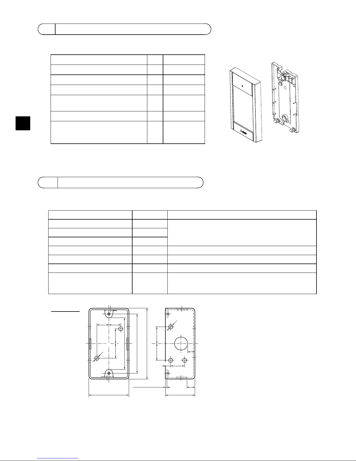
3 Component names and supplied parts
*3 ISO metric screw thread
*4 Remote controller cable is not included.
4 Field-supplied parts/Required tools
Parts name Qty. Notes
Single switch box 1 Not required for direct wall installation
Thin metal conduit Necessary
Lock nut and bushing Necessary
Cable cover Necessary Required for routing remote controller cable along a wall
Putty Reasonable
Molly anchor Necessary
Remote controller cable
(Use a 0.3 mm² (AWG22) 2-core
sheathed cable.)
Necessary
Parts name Qty. Appearance
Remote controller (top case) 1 Right figure *1
Remote controller (bottom case) 1 Right figure *2
Roundhead cross slot screws M4×30 2 *3
Wood screw 4.1×16
(for direct wall installation)
2*3
Simple Manual 1
CD-ROM (this manual)
Instruction Book and Installation
Manual
1
Bottom case *2
Top case *1
h
16 (5/8) 16 (5/8)
25 (1)
25 (1)
102 (4)
54 (2-1/8)
20
(13/16)
10
(3/8)
44 (1-3/4)
(3-3/8±1/32)
ø6 (1/4OD)
20 (13/16)
6
(1/4)
ø6 (1/4OD)
20 (13/16)
Switch box
unit: mm (in)
1.5 (1/16) or less
83.5±0.4
Page 7
– 7 –
GB
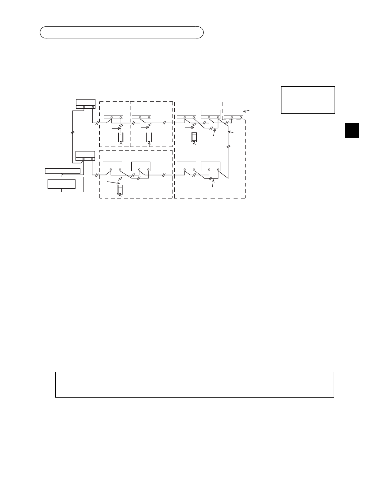
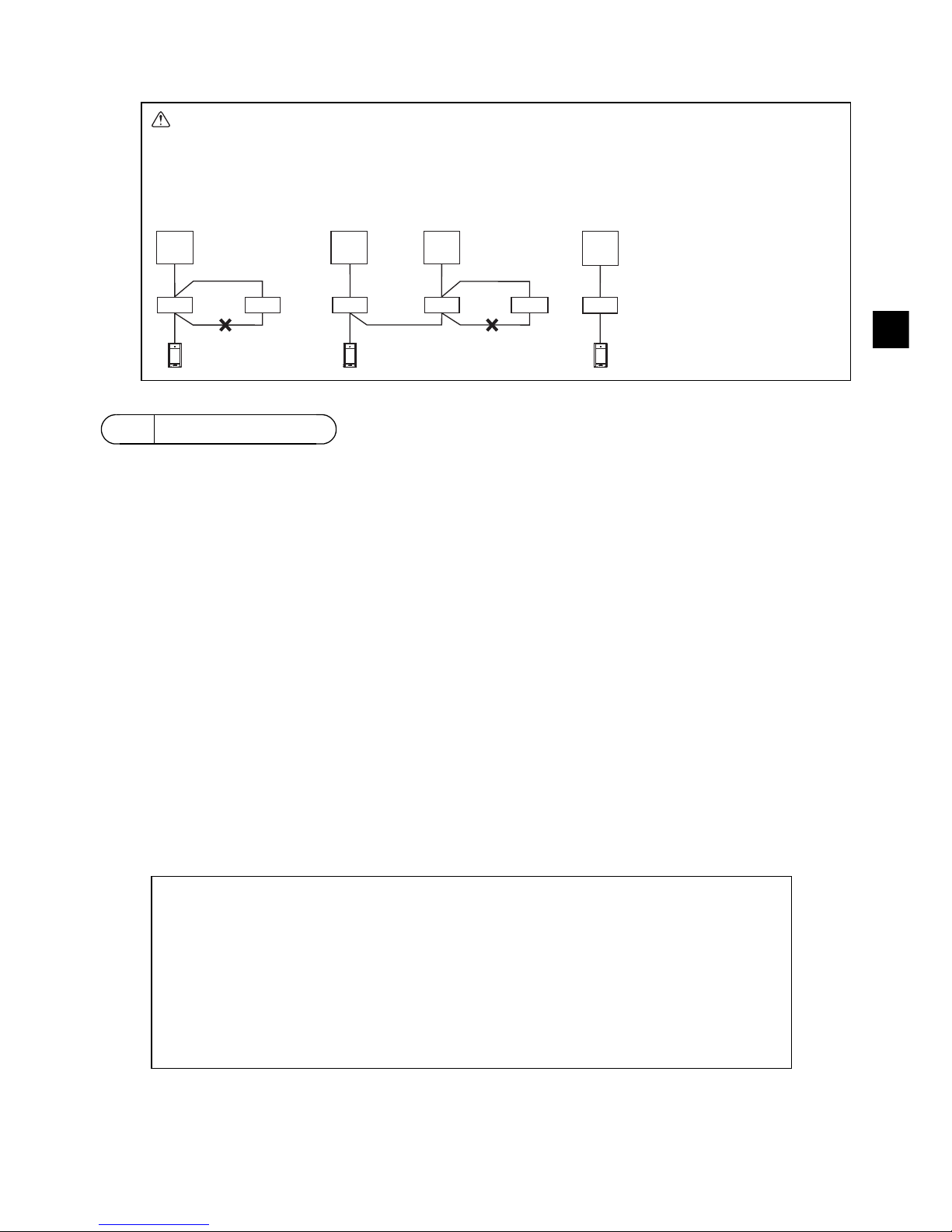
The wiring is different when the remote controller is connected to a CITY MULTI control system (“-A”
type and later) and when it is connected to a Mr. SLIM air conditioner (A control type). The wiring also
differs with the system configuration. Check the system used.
1. Connecting to CITY MULTI control system
The numbers (1) to (4) in the figure correspond to items (1) to (4) in the following description.
(1) Wiring from the remote controller
• Connect to the MA remote controller terminal block (TB15) on the indoor unit.
• The terminal block has no polarity. Connect to the terminal block at the bottom of the remote
controller case.
(2) Operating in a group (Groups 03, and 04 above)
• Interconnect the MA remote controller terminal block (TB15) of the indoor units you want to
operate as a group, and connect the MA remote controller to that point.
• When the remote controller is used in combination with the system controller as shown in the
figure above, group setting at the system controller (central controller in the figure above) is
necessary.
(3) Number of connectable remote controllers
• Only one remote controller can be connected to a group made up of indoor units.
• The MA Touch Remote Controller cannot be used in combination with other MA remote
controllers.
(4) To interlock to a LOSSNAY or OA processing unit, make the following settings using the remote
controller. (For a description of how to set an interlock, see section 11 “Service menu” (5)
“LOSSNAY setting”.)
Set the LOSSNAY or OA processing unit address and the address of all the indoor units you want
to interlock.
(5) Total length of remote controller wiring
• The MA Touch Remote Controller can be wired up to 70 m (229 ft).
5 How To Wire Transmission Line
Connect to TB15
on the indoor unit.
a Outdoor unit
b Indoor unit
c LOSSNAY or
OA processing unit
d Touch Remote Controller
e Central controller
f Power supply unit for
transmission line
TB5 TB15
TB5 TB15
bb
TB5 TB15
c
TB5 TB15
b
TB5 TB15
b
TB5 TB15
b
TB5 TB15
b
TB7 TB3
TB5 TB15
TB5 TB15
TB7 TB3
(1)
(1)
(3)
(3)
(3)
(3)
(2)
(2)
(2)
(4)
(1)
(1)
a
a
dd d
d
bb
e
f
Address = 51
Address = 01 Address = 02
Address = 55
Address = 08
Address = 07
Address = 03
Address = 04 Address = 09
Address = 06
Address = 05
Group 01 Group 02 Group 03
Group 04
NOTE: When interlocking the MA remote controller with a LOSSNAY or OA processing unit,
always set the address of all the indoor units in the group and the address of the
LOSSNAY or OA processing unit.
Page 8
– 8 –
GB
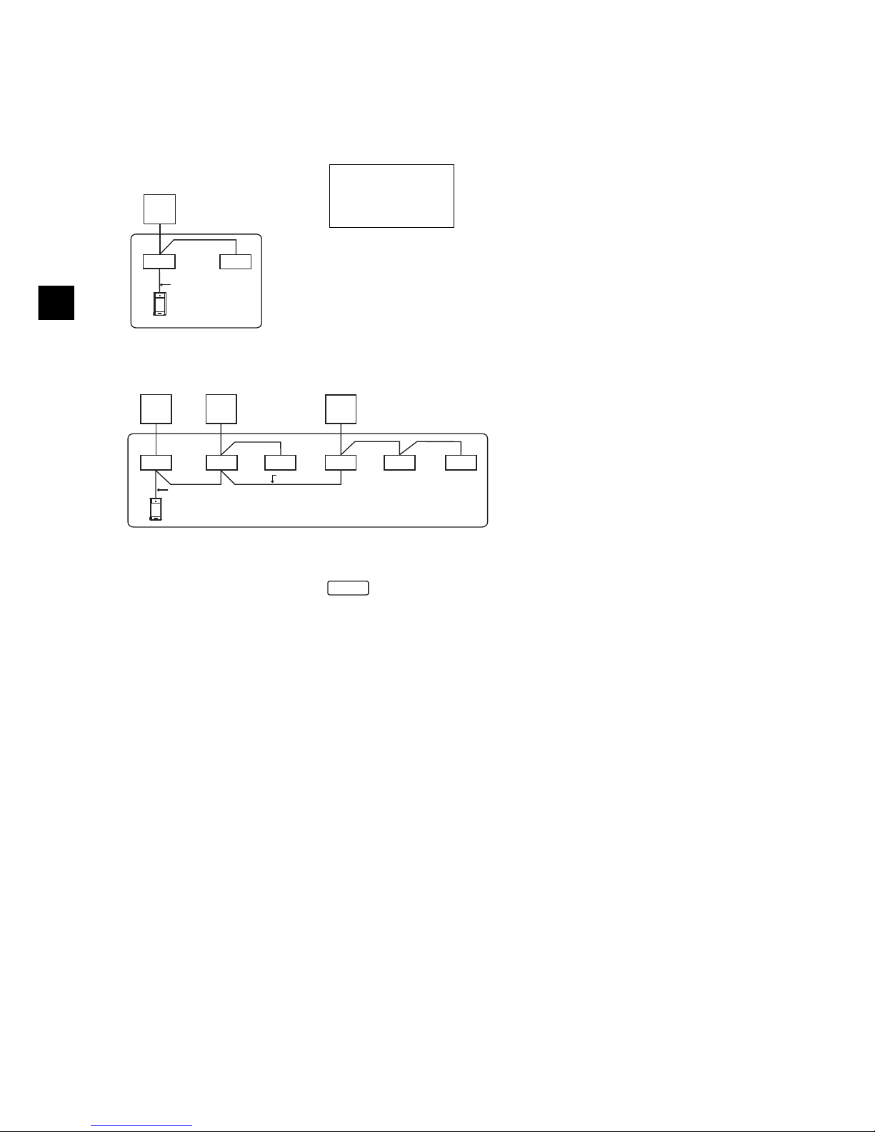
2. Connecting to Mr. SLIM air conditioner
The remote controller wiring depends on the system configuration. Check the system configuration.
Wire the remote controller as shown in the example below.
The numbers (1) to (3) in the figure correspond to items (1) to (3) in the following description.
[1] Connecting the remote controller for each refrigerant system (Standard 1:1, simultaneous twin,
simultaneous triple, simultaneous four)
[2] When grouping by different refrigerant systems
* Set the refrigerant address using the outdoor unit dip switches. (For more information, refer to the
outdoor unit installation manual.)
* All the indoor units enclosed in are controlled as one group.
(1) Wiring from remote controller
• Connect to indoor unit TB5 (remote controller terminal block). (The terminal block has no polarity.)
• For simultaneous multi type, when mixing various types of indoor units, always connect the
remote controller to the indoor unit with the most functions (wind velocity, vane, louver, etc.).
(2) When grouping with difference refrigerant systems
• Group using the remote controller wiring. Connect the remote controller to an arbitrary indoor unit
of each refrigerant system you want to group.
• When mixing different types of indoor units in the same group, always make the outdoor unit
connecting the indoor unit with the most functions (wind velocity, vane, louver, etc.) the Main unit
(refrigerant address = 00). Also, when the Main unit is the simultaneous multi type, always satisfy
the conditions of (1) above.
• The MA Touch Remote Controller can control up to 16 refrigerant systems as one group.
(3) Only one remote controller can be connected to each group. The remote controller cannot be
used in combination with other MA remote controllers.
Connect to TB5
on the indoor unit.
a Outdoor unit
b Indoor unit
d Touch Remote Controller
(1)
TB5
TB4
TB1
TB4
(3)
a
bb
d
Refrigerant
address = 00
Simultaneous twin
TB4
TB4
TB4
TB4
TB4TB4
TB1 TB1 TB1
TB5
TB5
TB5
(2)
(1)
(3)
(2)
aa a
bbbbbb
d
Standard 1:1 Simultaneous twin
Simultaneous triple
Refrigerant
address = 01
(Sub)
Refrigerant
address = 00
(Main)
Refrigerant
address = 02
(Sub)
Page 9
– 9 –
GB
(4) Total length of remote controller wiring
• The MA Touch Remote Controller can be wired up to 150 m (492 ft).
This remote controller is for the wall installation. It can be installed either in the switch box or directly
on the wall. When performing direct wall installation, wires can be thread through either back or top of
the remote controller.
(1) Selecting an installation site
Install the remote controller (switch box) on the site where the following conditions are met.
(a) For connection to the indoor unit with an Auto descending panel, a place where people can check
the Auto descending panel operation of the indoor unit while they are operating the remote
controller (Refer to the indoor unit Instructions Book for how to operate Auto descending panel.)
(b) A flat surface
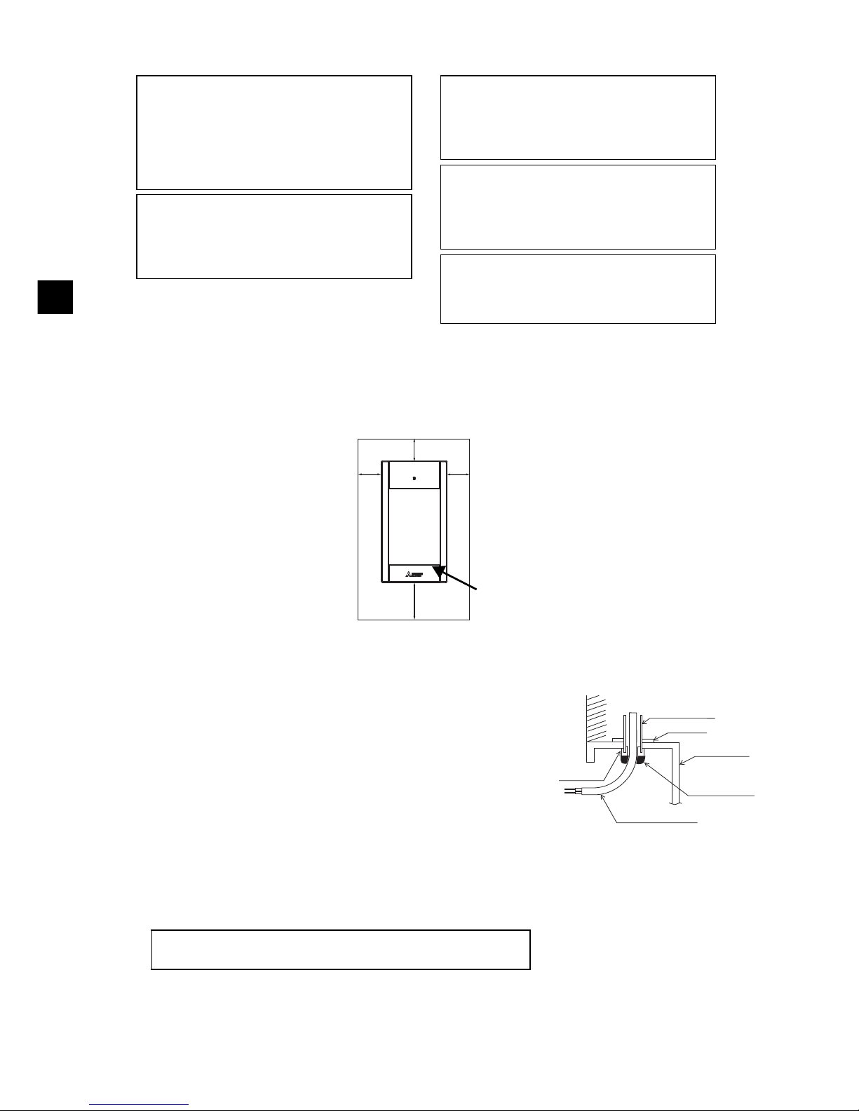
(c) A place where the remote controller can measure the accurate indoor temperature
Sensors to monitor indoor temperature are on the indoor unit and on the remote controller. When
the room temperature is monitored with the sensor on the remote controller, the built-in sensor on
the remote controller monitors the room temperature. When using the sensor on the remote
controller, follow the instructions below.
• To monitor the accurate indoor temperature, install the remote controller away from direct
sunlight, heat sources, and the supply air outlet of the air conditioner.
• Install the remote controller in a location that allows the sensor to measure the representative
room temperature.
• Install the remote controller where no wires are routed around the temperature sensor on the
controller. (If wires are routed, the sensor cannot measure accurate indoor temperature.)
CAUTION - The wiring cannot be connected to TB5 of the indoor unit of the same
refrigerant system. If so connected, the system will not operate normally.
- Remote controllers cannot be wired together. Only one wire can be connected
to the remote controller terminal block.
a Outdoor unit
b Indoor unit
d Touch Remote
Controller
6How To Install
d
d
TB4
TB4
TB4
TB4
TB4
TB4
TB1
TB1 TB1
TB1
TB5
TB5
TB5
TB5 TB5 TB5
a
bbb bbb
d
aa a
Refrigerant
address = 00
Refrigerant
address = 00
Refrigerant
address = 01
Refrigerant
address = 00
Simultaneous twin Standard 1:1 Simultaneous twin Standard 1:1
■ Discrepancy between the indoor temperature measured at the wall and the actual
indoor temperature may occur.
If the following conditions are met, the use of the temperature sensor on the indoor unit is
recommended.
• Supply air does not reach to the wall easily where the remote controller is installed due to
improper airflow distribution.
• There is a great discrepancy between the wall temperature and the actual indoor
temperature.
• The back side of the wall is directly exposed to the outside air.
Note: When temperature changes rapidly, the temperature may not be detected accurately.
Important
Page 10
– 10 –
GB
(2) Installation space
Leave a space around the remote controller as shown in the figure shown below, regardless of
whether the controller is installed in the switch box or directly on the wall. Removing the remote
controller will not be easy with insufficient space.
Also, leave an operating space in front of the remote controller.
(3) Installation work
Controller can be installed either in the switch box or directly on the
wall. Perform the installation properly according to the installation
method.
1 Drill a hole in the wall.
■ Installation using a switch box
• Drill a hole in the wall, and install the switch box on the wall.
• Connect the switch box to the conduit tube.
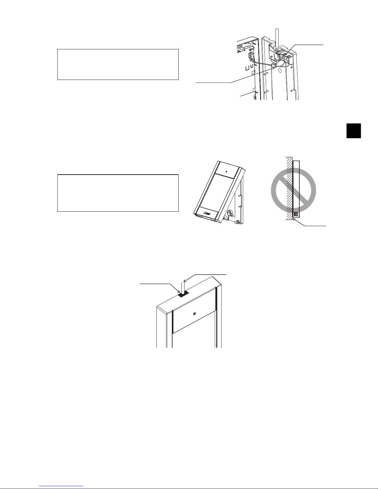
■ Direct wall installation
• Drill a hole in the wall, and thread the cable through it.
2 Seal the cable access hole with putty.
■ Installation using a switch box
• Seal the remote controller cable access hole at the
connection of switch box and conduit tube with putty.
Do not install the controller in a place where
the difference between the remote controller
surface temperature and the actual room
temperature will be great.
If the temperature difference is too high,
room temperature may not be adequately
controlled.
To reduce the risk of malfunctions, do not
install the controller in a place where water
or oil may come into contact with the
controller, or in a condensing or corrosive
environments.
To avoid deformation and malfunction, do
not install the remote controller in direct
sunlight or where the ambient temperature
may exceed 40ºC (104ºF) or drop below 0ºC
(32ºF).
To reduce the risk of malfunctions and
damage to the controller, avoid installing the
remote controller on an electrically
conductive surface, such as an unpainted
metal sheet.
Refer to either of the following manuals for
temperature sensor setting: indoor unit
Installation Manual for CITY MULTI; this
manual for Mr. SLIM.
30
(1-3/16)
30
(1-3/16)
30 (1-3/16)
50 (1-31/32)
Temperature sensor
Unit: mm (in)
External dimensions of remote controller
Minimum required space
around the remote
controller
Wall
Conduit tube
Locknut
Switch box
Seal the gap
with putty.
Remote
controller cable
Bushing
To reduce the risk of electric shock, malfunctions, or fire, seal
the gap between the cables and cable access holes with putty.
Page 11
– 11 –
GB
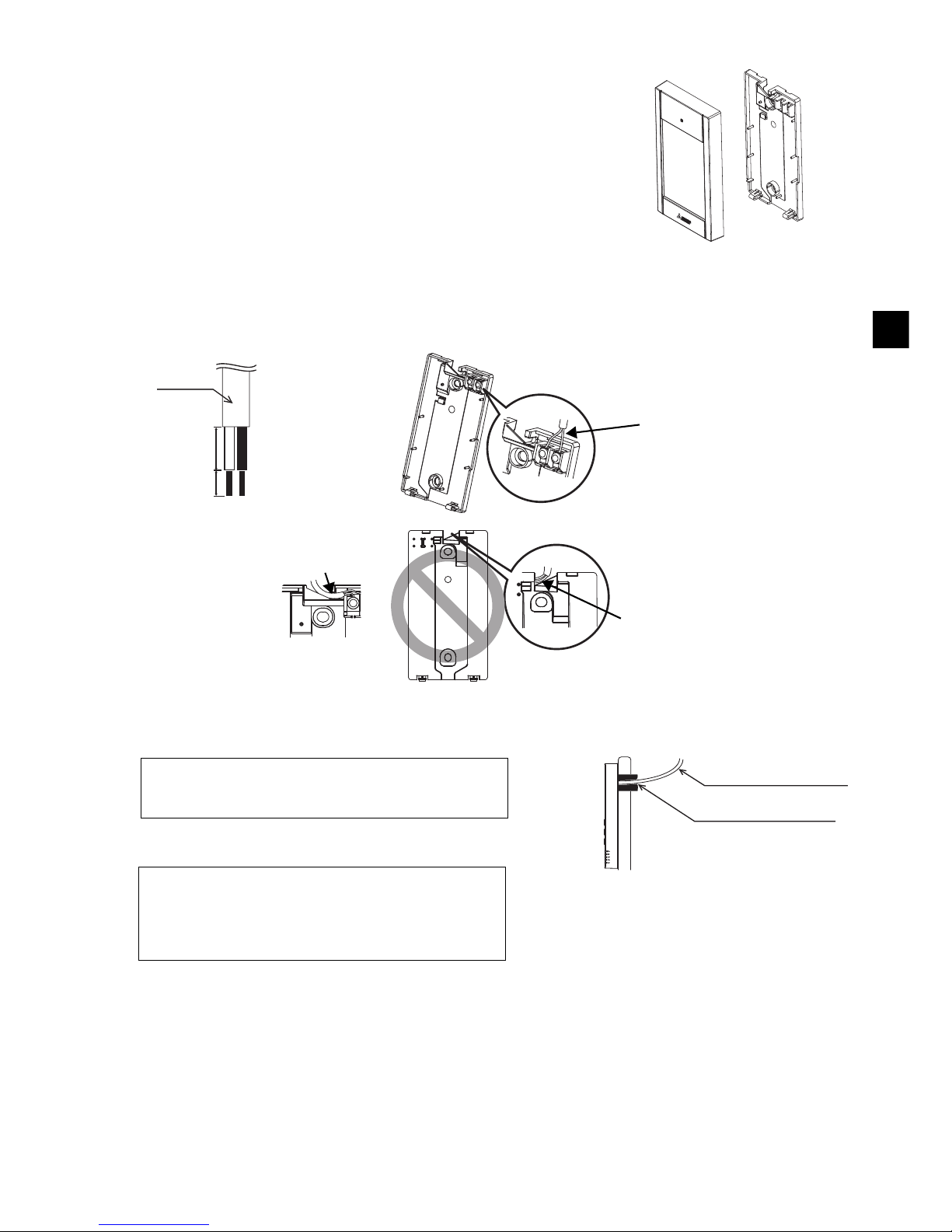
3 Prepare the bottom case of the remote controller.
4 Connect the remote controller cable to the terminal block on the bottom case.
Peel off the remote controller cable sheath as shown below to connect to the terminal block properly.
Secure the remote controller cable so that the peeled part of the cable will fit into the case.
■ Direct wall installation
• Seal the hole through which the cable is threaded with putty.
Top case Bottom case
16 (21/32)
6 (1/4)
Sheath
Unit: mm (in)
Connect the cable.
(non-polarized)
2-core wire must not be
seen on the back.
Insert the sheathed part of the cable inside
the case, and then secure the cable.
Seal the gap with putty.
Route the cable behind
the remote controller.
Remote controller cable
To reduce the risk of electric shock, shorting, or
malfunctions, keep wire pieces and sheath shavings
out of the terminal block.
Do not use solderless terminals to connect cables to
the terminal block.
Solderless terminals may come in contact with the
circuit board and cause malfunctions or damage the
controller cover.
Important
Page 12
– 12 –
GB
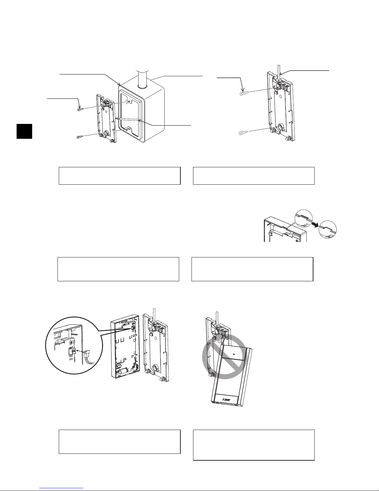
5 Install the bottom case.
Be sure to secure two places of the bottom case.
6 Cut out the cable access hole.
■ Direct wall installation (when running the cable along the wall)
• Cut out the thin-wall part on the cover (the shaded area in the right
figure) with a nipper.
• Thread the cable from the groove behind the bottom case through
this access hole.
7 Connect the connector to the top case.
Connect the connector on the bottom case to the socket on the top case.
■ Installation using a switch box ■ Direct wall installation
Remote
controller
cable
Refer to 4.
Refer to 2.
Single switch box
Roundhead
cross slot
screws
Seal the cable
access hole
with putty.
Refer to 4.
Wood
screws
Remote
controller cable
To avoid deformation and damage to the
bottom case, do not overtighten the screws.
To avoid damage to the bottom case, do not
make holes on it.
Important
Notice
To prevent damage to the circuit board,
remove the front cover from the top case
before cutting out a cable access hole.
Note that accidentally touching the circuit
board may damage the circuit board when
cutting out a cable access hole.
Connect the connector.
To prevent malfunctions, do not remove the
protective sheet or the circuit board from the
top case.
To prevent cable breakage and
malfunctions, do not hang the top controller
casing hang by the cable as shown in the
figure above.
Important
Page 13
– 13 –
GB
8 Insert the wires into the clamp.
9 Install the top case on the bottom case.
Two mounting tabs are at the top of the top case.
Hook those two tabs onto the bottom case, and click the top case into place. Check that the case is
securely installed and not lifted.
■ Direct wall installation (when running the cable along the wall)
• Thread the cable through the access hole at the top of the remote controller.
• Seal the cut-out part of the cover with putty.
• Use a cable cover.
Clamp
Insert the wires.
Hold the wires in place with the clamp to
prevent undue force from being applied to
the terminal block and causing cable
breakage.
Important
Wall
Should not
be lifted.
When attaching the top casing to the bottom
casing, push it until it they click into place.
If they are not properly locked into place,
they may fall, causing personal injury,
controller damage, or malfunctions.
Important
Seal the gap
with putty.
Use a cable
cover.
Thread the cable through the top of the
remote controller.
Page 14
– 14 –
GB
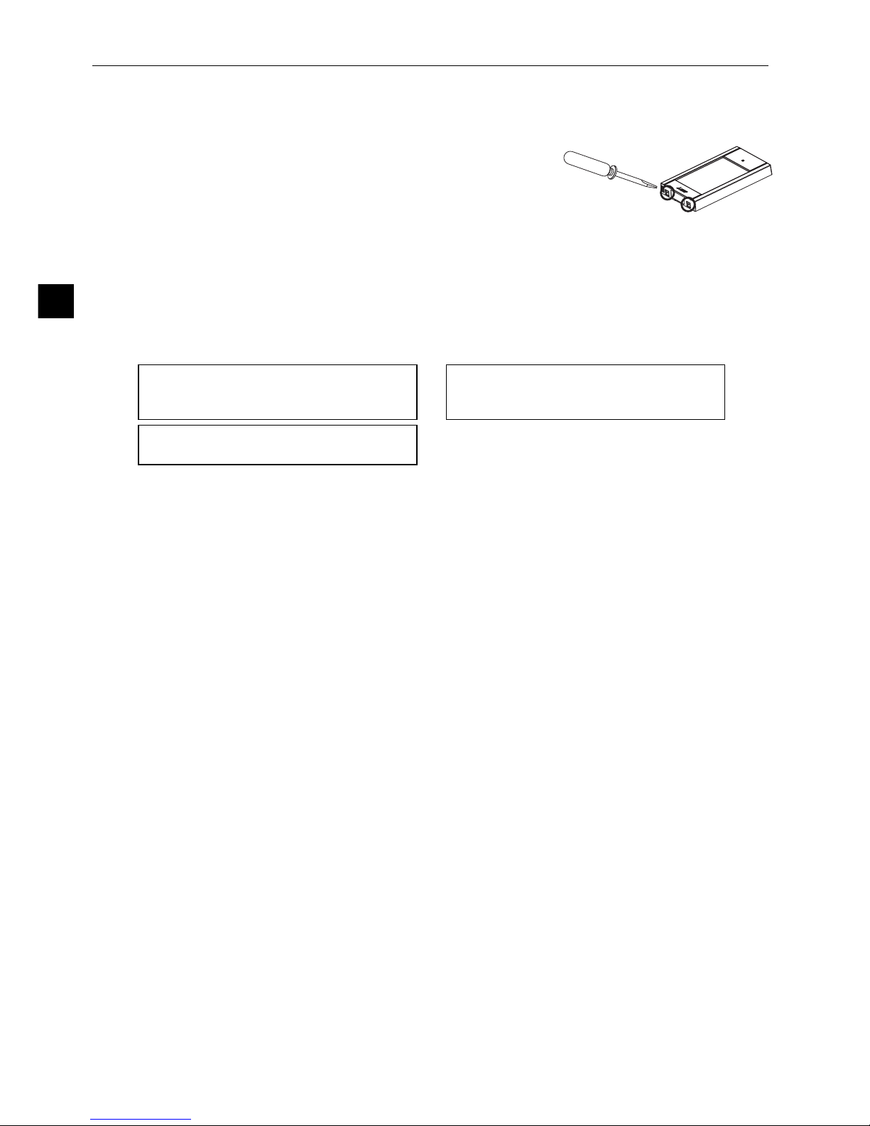
• Uninstalling the top case
1 Uninstalling the top case
Insert a flat-tip screwdriver with a blade width of 3-5 mm (1/8-7/32
inch) into the latches at the bottom of the remote controller and lift
the latches. Then, pull up the top case.
■ At the time of factory shipment, protective sheet is on the operation interface of the front
cover. Peel off the protective sheet on the operation interface prior to use.
To prevent damage to the controller casing,
do not force the flat-tip screwdriver to turn
with its tip inserted in the slot.
Do not insert the flat-tip screwdriver too far.
Doing so will damage the circuit board.
To prevent damage to the controller casing,
use a flat-head screwdriver with a blade
width of 3-5 mm (1/8-7/32 inch).
Important
Page 15

– 15 –
GB
7 Remote controller button functions
(7) Touch panel & Backlit
full color LCD
(2) Function buttons
(6) Operation indicator
(11) Up/Down buttons
(4) RETURN button
(3) MENU button
(5) SELECT button
Main display Menu screen
(8) Setting button
(9) Left button
(12) Fan speed
shortcut button
(10) Right button
(13) Vane shortcut button
(1) ON/OFF button
(1) ON/OFF button
Use to turn ON/OFF the indoor unit.
(2) Function buttons
Use to select the operation mode or to set the
temperature and fan speed on the Main display.
Use to select items on other screens.
(3) MENU button
Use to bring up the Main menu.
(4) RETURN button
Use to return to the previous screen.
(5) SELECT button
Use to jump to the setting screen or to save the
settings.
(6) Operation indicator
Stays lit during normal operation. Blinks during
startup and when an error occurs.
(7) Touch panel & Backlit full color LCD
Dot display. When the backlight is off, pressing
any area turns the backlight on and it will stay lit
for a certain period of time depending on the
screen. Performing any button operation keeps
the backlight on.
(8) Setting button
Use to bring up the Main menu.
When the menu operation is locked, an
administrator password is required.
(9) Left button
Use to switch the setting items in the following
order: louver, ventilation, vane, fan speed,
operation mode, and preset temperature.
(10) Right button
Use to switch the setting items in the following
order: preset temperature, operation mode, fan
speed, vane, ventilation, and louver.
Note: When the backlight is off, pressing any area
turns the backlight on and does not perform
its function.
(11) Up/Down buttons
Use to change the contents of the setting
selected in (9) and (10) above.
(12) Fan speed shortcut button
Use to directly access the fan speed settings
screen.
(13) Vane shortcut button
Use to directly access the vane settings screen.
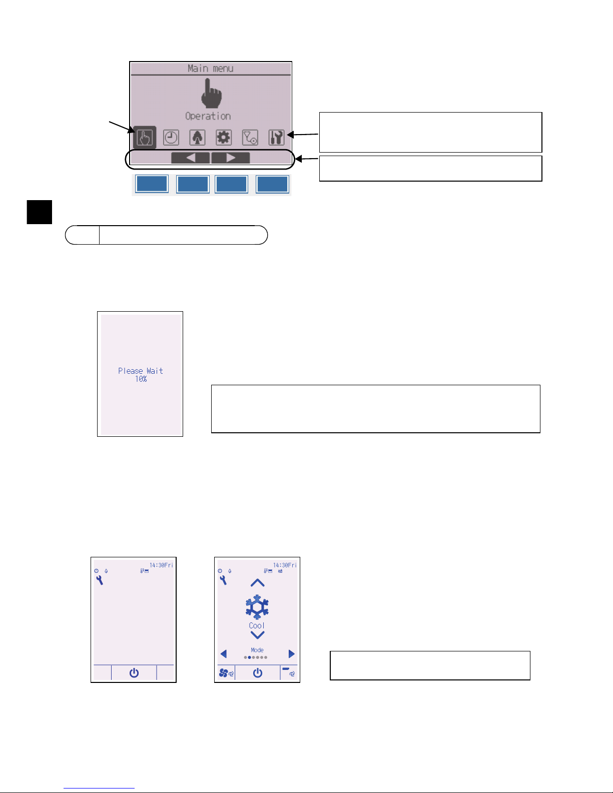
Pressing the Setting button will bring up the Main
menu as shown below.
Operation menu *1
Timer menu *1
Energy saving menu *1
Initial setting menu *2*3
Maintenance menu *1
Service menu *2*3
*1 Refer to the Instructions Book in the CD-ROM
for details.
*2 Explained in this manual.
*3 If no buttons are pressed for 10 minutes on the
initial setting screens, or 2 hours on the service
screens (10 minutes on some screens), the
screen will automatically return to the Main
display. Any settings that have not been saved
will be lost.
The available items on the menu depend on the
connected indoor unit model. For items not
described in the manuals that are enclosed with
the MA Touch Remote Controller, refer to the
manuals that came with the air conditioning units.
Page 16
– 16 –
GB
Button operations on the Main menu
Make sure that the MA remote controller is properly installed according to the instructions in the
Installation Manual and that the indoor and outdoor unit installation has been completed before
turning on the power.
(1) When the power is turned on, the following screen will appear.
(2) Main display
After the successful startup, the Status display will appear. While the Status display is displayed,
pressing any area switches the screen to the Main display. The Main display can be displayed in
two different modes: “Full” and “Basic.” Refer to section 10 “Initial settings” for how to select the
display mode. (The factory setting is “Full.”)
8 Turning on the power
Normal start up (indicating the
percentage of process completion)
Main display in the Full mode
(while the unit is not in operation)
Main display in the Full mode
(while the unit is in operation)
Cursor
Move the cursor to the desired function with the F2
and F3 buttons, and press the SELECT button to go
to the next page. Password may be required.
Button function guide will appear at the bottom of the
screens.
F1 F2 F3 F4
Note: When the power is on for the first time, the Language selection screen
will be displayed. Refer to section 10 (4) under “Display setting menu”.
Select a desired language. The system will not start-up without language
selection.
Note: Refer to the Instruction Book for the
icons on the display.
Page 17
– 17 –
GB
(1) Read the section about Test run in the indoor unit Installation Manual before performing a test
run.
(2) At the Main display, press the Setting button and select Service>Test run>Test run.
(3) Press the ON/OFF button to cancel the test run if necessary.
(4) Refer to the indoor unit Installation Manual for the detailed information about test run and for
how to handle the errors that occur during a test run.
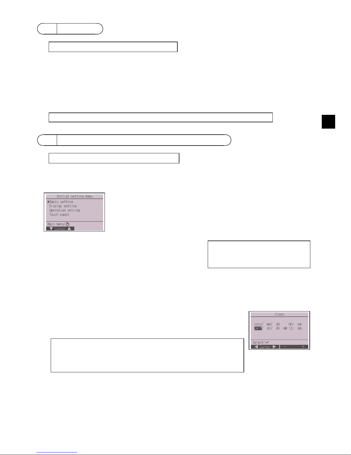
From the Main display, select Main menu>Initial setting, and make the remote controller settings on
the screen that appears.
Basic setting menu
(1) Clock setting
[Button operation]
9 Test run
10 Initial settings (Remote controller settings)
Basic setting menu
•Clock
• Daylight saving time
• Administrator password
Display setting menu
• Main display
• Remote controller display
details setting
• Brightness
• Language selection
•Design
Operation setting menu
• Auto mode
Touch panel menu
(Refer to the Instruction Book.)
1 Move the cursor with the F1 or F2 button to the desired item.
2 Change the date and time with the F3 or F4 button, and press the
SELECT button to save the change. The change will be reflected on
the clock display on the Status display and the Main display.
Note: Clock setting is necessary for time display, weekly timer, timer setting and
error history. Make sure to perform clock setting when the unit is used for
the first time or has not used for a long time.
Note: If a given system has no system controllers, the clock time will not
automatically be corrected. In this case, periodically correct the clock time.
Note: Maintenance password is required.
Note: Refer to section 11 “Service menu” for information about the maintenance password.
Note: Administrator password is required.
Note: The initial administrator password
is “0000.” Refer to section (3)
“Administrator password setting”
for how to change the password.
Page 18
– 18 –
GB
(2) Daylight saving time
[Button operation]
(3) Administrator password setting
[Button operation]
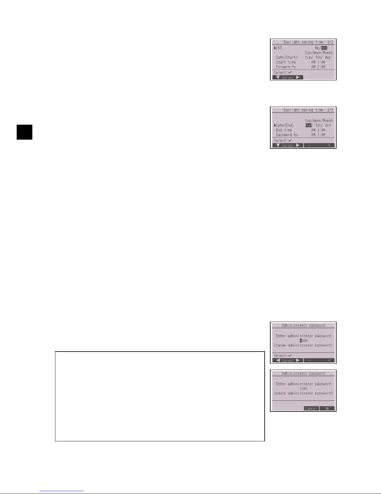
The start/end time for daylight saving time can be set. The daylight saving
time function will be activated based on the setting contents.
• If a given system has a system controller, disable this setting to keep
the correct time.
• At the beginning and the end of daylight saving time, the timer may go
into action twice or not at all.
• This function will not work unless the clock has been set.
1 The daylight saving time function can be activated/deactivated or the
start/end times can be set by using the F1 through F4 buttons.
•DST
Select “Yes” to activate the daylight saving time, or select “No” to
deactivate.
• Date(Start)
Set the start day of the week, week number, and month for daylight
saving time.
• Start time
Set the start time for daylight saving time.
• Forward to
Set the time when the clock is to be set forward to at the start time
above.
• Date(End) (2nd page)
Set the end day of the week, week number, and month for daylight
saving time.
• End time (2nd page)
Set the end time for daylight saving time.
• Backward to (2nd page)
Set the time when the clock is to be set backward to at the end time
above.
2 Press the SELECT button to save the setting.
* If “5th” is selected for the week number and the 5th week does not exist in the
selected month of the year, the setting is considered to be “4th.”
1 A window to enter a new password will appear. Enter a new password,
and press the SELECT button.
2 Press the F4 button (OK) on the password change confirmation screen
to save the change. Press the F3 button (Cancel) to cancel the change.
Note: The initial administrator password is “0000.” Change the default password
as necessary to prevent unauthorized access. Have the password
available for those who need it.
Note: If you forget your administrator password, you can initialize the password
to the default password “0000” by pressing and holding the F1 button for
ten seconds on the administrator password setting screen.
Note: The administrator password is required to make the settings for the
following items.
· Timer setting · Weekly timer setting · Energy-save setting
· Outdoor unit silent mode setting · Restriction setting
· Night setback setting · Initial setting
Refer to the Instruction Book that came with the remote controller for the
detailed information about how to make the settings for these items.
Page 19
– 19 –
GB
Display setting menu
(1) Main display setting
[Button operation]
(2) Remote controller display details setting
[1] Clock display
[Button operation]
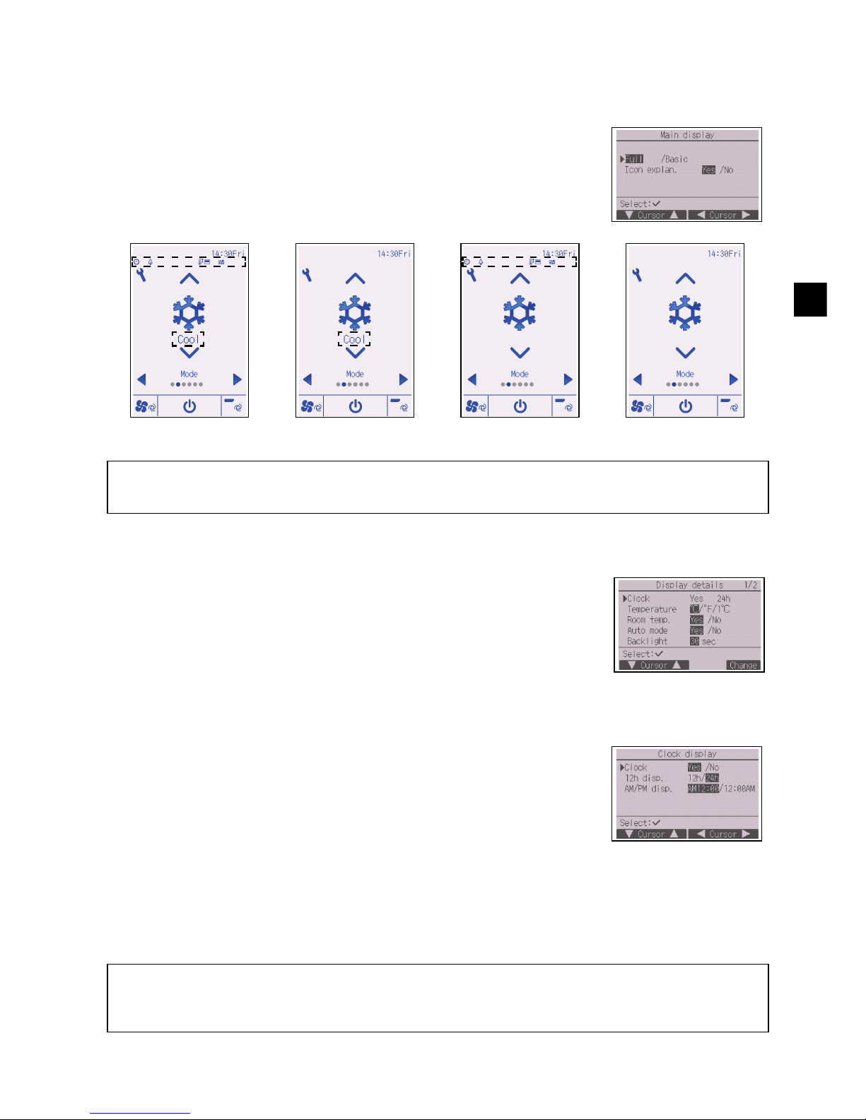
1 Move the cursor to “Full/Basic,” and use the F3 or F4 button to select
the display mode “Full” or “Basic.” (The factory setting is “Full.”)
2 Move the cursor to “Icon explan.” and use the F3 or F4 button to select
the display mode “Yes” or “No.” (The factory setting is “Yes.”)
Example: Full mode
(Icon explanation enabled)
Example: Basic mode
(Icon explanation enabled)
Example: Full mode
(Icon explanation disabled)
Example: Basic mode
(Icon explanation disabled)
Note: This setting is only for the Main display. In the Basic mode, icons that indicate control status on timer and
schedule settings will not appear on the display. When “No” is selected, the explanation of the setting
contents on the Main display will not appear.
Make the settings for the remote-controller-related items as necessary.
Press the SELECT button to save the changes.
1 Select “Clock” from the display details setting screen, and press the
F4 button (Change) to bring up the clock display setting screen.
2 Use the F1 through F4 buttons to select “Yes” (display) or “No” (non-
display) and its format for the Status display and the Main display.
3 Save the settings with the SELECT button. (The factory settings are
“Yes” (display) and “24 h” format.)
Clock display: Yes (Time is displayed on the Status display and the Main display.)
No (Time is not displayed on the Status display and the Main display.)
Display format: 24-hour format
12-hour format
AM/PM display (Effective when the display format is 12-hour): AM/PM before the time
AM/PM after the time
Note: Time display format will also be reflected on the timer and schedule setting display. The time is displayed
as shown below.
12-hour format: AM12:00 ~ AM1:00 ~ PM12:00 ~ PM1:00 ~ PM11:59
24-hour format: 0:00 ~ 1:00 ~ 12:00 ~ 13:00 ~ 23:59
Page 20
– 20 –
GB
[2] Temperature unit setting
[Button operation]
[3] Room temperature display
[Button operation]
[4] Auto (single set point) mode display setting
[Button operation]
[5] Backlight
The backlight lighting-up time can be set.
[Button operation]
[6] LED lighting
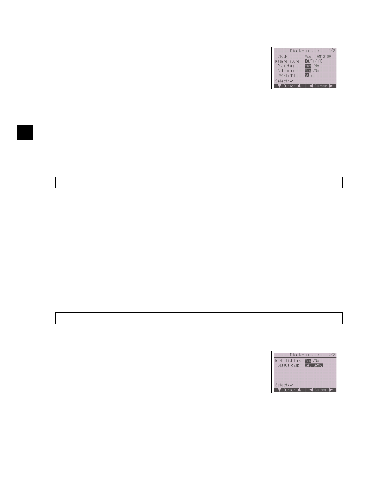
Move the cursor to “Temperature” from the display details setting screen,
and select the desired temperature unit with the F3 or F4 button. (The
factory setting is Centigrade (ºC).)
• ºC: Temperature is displayed in Centigrade. Temperature is displayed
in 0.5- or 1-degree increments, depending on the model of indoor
units.
• ºF: Temperature is displayed in Fahrenheit.
• 1 ºC: Temperature is displayed in Centigrade in 1-degree increments.
Move the cursor to “Room temp.” on the display details setting screen, and select the desired
setting with the F3 or F4 button.
(The factory setting is “Yes”.)
• Yes: Room temperature appears on the Main display.
• No: Room temperature does not appear on the Main display.
Note: Even when “Yes” is set, the room temperature is not displayed on the Main display in the “Basic” mode.
Move the cursor to “Auto mode” from the display details setting screen, and select the desired
mode with the F3 or F4 button. (The factory setting is “Yes.”)
• Yes: “Auto Cool” or “Auto Heat” is displayed during operation in the Auto (single set point) mode.
• No: Only “Auto” is displayed during operation in the Auto (single set point) mode.
Move the cursor to “Backlight” from the display details setting screen, and select the desired time
(5/10/20/30/60 seconds) with the F4 button. (The factory setting is “30” seconds.)
Note: This setting is effective on the Status display and the Main display.
The LED lighting can be set to either “Yes” (On) or “No” (Off). (The
factory setting is “Yes”.)
When “No” is selected, the LED will not light up even during the normal
operation.
Page 21
– 21 –
GB
[7] Status display
Make the settings for the temperature to be displayed on the Status display.
[Button operation]
(3) Brightness
[Button operation]
(4) Language selection
[Button operation]
(5) Design setting
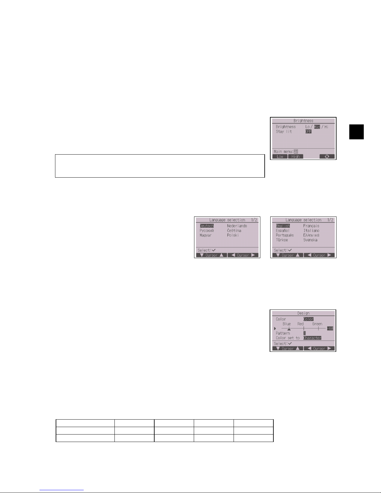
The screen design can be set.
[Button operation]
* At factory shipment, these items are set as follows.
Move the cursor to “Status disp.” from the display details setting screen, and select the desired
setting with the F4 button.
Each pressing the F4 button will toggle through the following options: Set temp., Room temp., and
Hide.
Select the desired brightness for the remote controller LCD with the F1
and F2 buttons.
The ON/OFF of the Stay lit mode can be switched with the F4 button.
When “ON” is selected, the backlight will remain lit dimly even after the
specified time has elapsed.
Note: Adjust the brightness to improve viewing in different lighting conditions or
installation locations. This setting can not improve viewing from all
directions.
Move the cursor to the language you desire with
the F1 through F4 buttons.
Press the SELECT button to save the setting.
Select the color option with the F4 button.
• Color: The display color can be selected.
• White: Monochrome display (white basis)
• Black: Monochrome display (black basis)
When “White” or “Black” is selected, press the SELECT button. When
“Color” is selected, select the following item with the F1 or F2 button, and
set the desired display color for each item.
• Color shade: Set the color shade with the F3 or F4 button. (The
settable range is -90 to 89.)
• Pattern: Set the color with the F4 button.
• Color set to: Select “Character” or “BG” (Background) as a target to
which the color is applied with the F4 button.
Color option Color shade Pattern Color set to
CT01MAA(R)-S, SB Color -70 1 Character
CT01MAA(R)-PB Color -90 2 Character
Page 22
– 22 –
GB
Operation setting menu
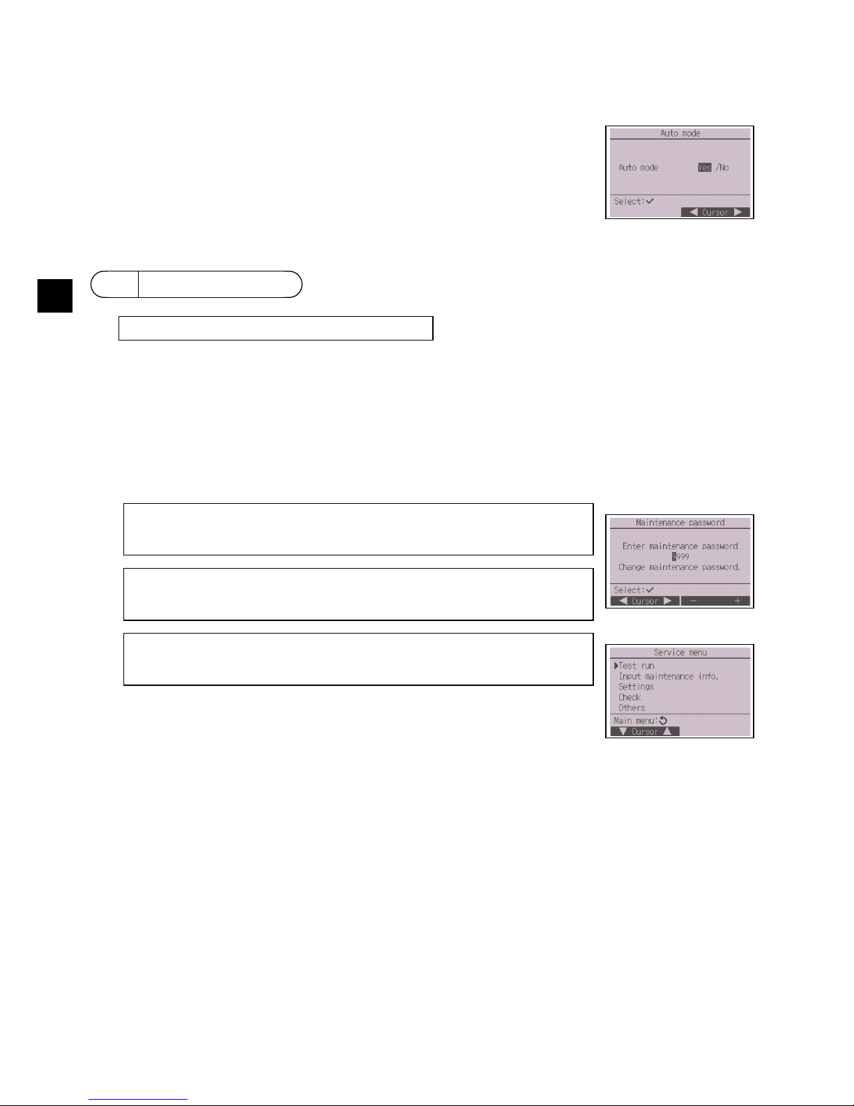
(1) Auto mode setting
[Button operation]
At the Main display, press the Setting button and select “Service” to make the maintenance settings.
When the Service menu is selected, a window will appear asking for the password.
To enter the current maintenance password (4 numerical digits), move the cursor to the digit you want
to change with the F1 or F2 button, and set each number (0 through 9) with the F3 or F4 button. Then,
press the SELECT button.
Whether or not to use the Auto (single set point) or Auto (dual set points)
mode can be selected by using the F3 or F4 button. This setting is valid
only when indoor units with the Auto mode function are connected.
(The factory setting is “Yes”.)
Press the SELECT button to save the changes made.
• Yes: The Auto mode can be selected in the operation mode setting.
• No: The Auto mode cannot be selected in the operation mode setting.
11 Service menu
Note: The initial maintenance password is “9999.” Change the default password
as necessary to prevent unauthorized access. Have the password
available for those who need it.
Note: If you forget your maintenance password, you can initialize the password
to the default password “9999” by pressing and holding the F1 button for
ten seconds on the maintenance password setting screen.
Note: Air conditioning units may need to be stopped to make certain settings.
There may be some settings that cannot be made when the system is
centrally controlled.
Note: Maintenance password is required.
Page 23
– 23 –
GB
(1) Test run (CITY MULTI and Mr. SLIM)
(2) Input maintenance information (CITY MULTI and Mr. SLIM)
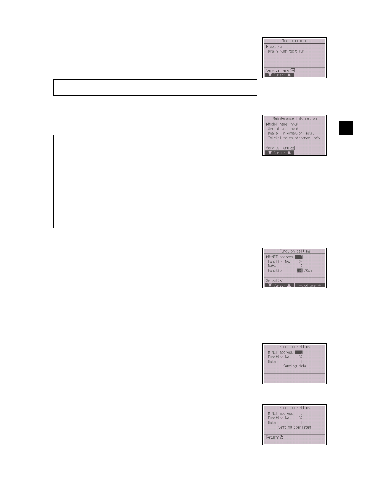
(3) Function setting (CITY MULTI)
[Button operation]
Select “Test run” from the Service menu to bring up the Test run menu.
• Test run: Select this option to perform a test run.
• Drain pump test run: Select this option to perform a test run on the
drain pump on the indoor unit.
Applicable only to the type of indoor units that support the test run
function.
Note: Refer to the indoor unit Installation Manual for the detailed information
about test run.
Select “Input maintenance info.” from the Service menu to bring up the
Maintenance information screen. Refer to the indoor unit Installation
Manual for how to make the settings.
Note: The following settings can be made from the Maintenance information
screen.
·Registering model names and serial numbers
Enter the model names and serial numbers of outdoor and indoor units.
The information entered will appear on the Error information screen.
Model names can have up to 18 characters, and the serial numbers can
have up to 8 characters.
·Registering dealer information
Enter phone number of a dealer. The entered information will appear on
the Error information screen. Phone number can have up to 13
characters.
·Initializing maintenance information
Select the desired item to initialize the model name, serial number, and
dealer information settings.
Make the settings for the indoor unit functions via the remote controller as
necessary.
Select “Function setting” from the Settings menu to bring up the Function
setting screen.
1 The Function setting screen will appear.
Press the F1 or F2 button to move the cursor to one of the following: M-NET address, function
setting number, or setting value. Then, press the F3 or F4 button to change the settings to the
desired settings.
2 Once the settings have been completed, press the SELECT button.
A screen will appear that indicates that the settings information is being
sent.
To check the current settings of a given unit, enter the setting for its MNET address and function setting number, select Conf for the Function,
and press the SELECT button.
A screen will appear that indicates that the settings are being searched
for. When the search is done, the current settings will appear.
3 When the settings information has been sent, a screen will appear that
indicates its completion.
To make additional settings, press the RETURN button to return to the
screen shown in Step 2 above. Set the function numbers for other
indoor units by following the same steps.
Page 24
– 24 –
GB
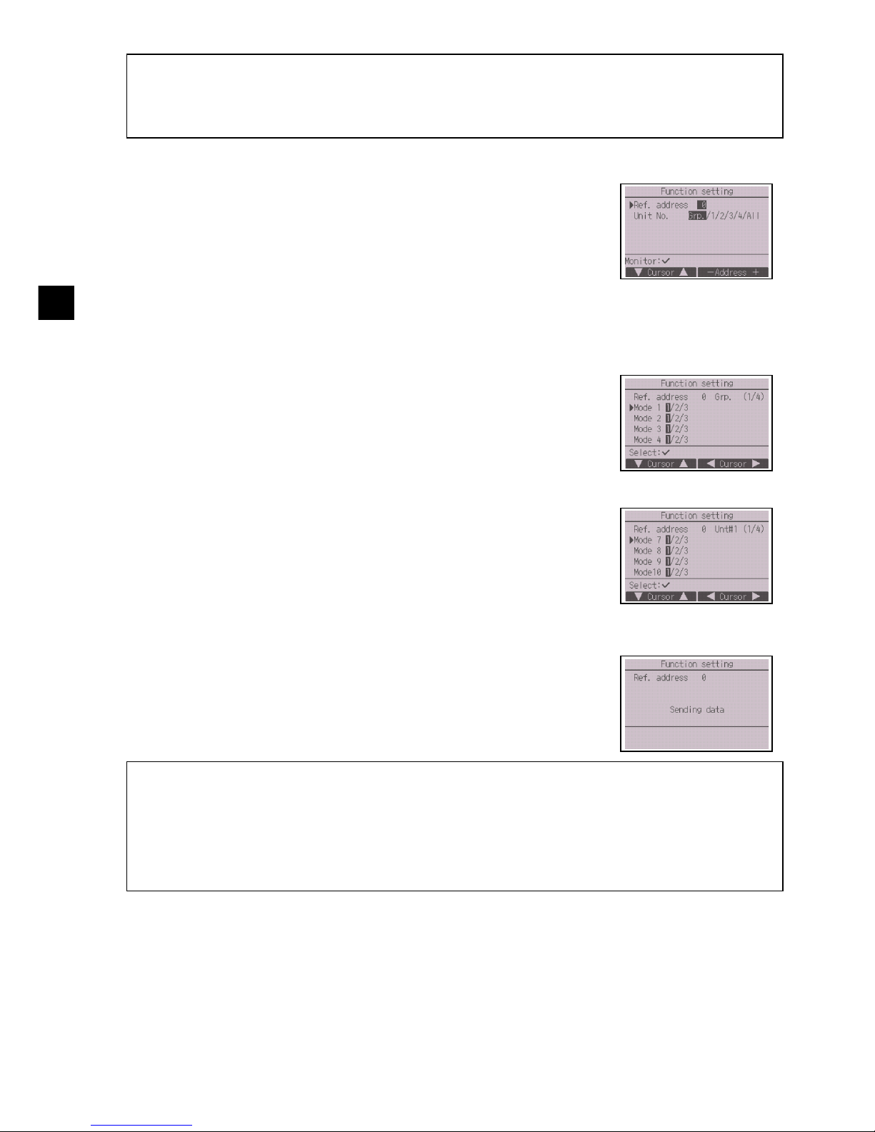
(4) Function setting (Mr. SLIM)
[Button operation]
Note:
· Refer to the indoor unit Installation Manual for information about the factory settings of indoor units,
function setting numbers, and setting values.
· Be sure to write down the settings for all functions if any of the initial settings has been changed after the
completion of installation work.
Make the settings for the indoor unit functions via the remote controller as
necessary.
Select “Function setting” from the Settings menu to bring up the Function
setting screen.
1 Set the indoor unit refrigerant addresses and unit numbers with the F1 through F4 buttons, and
then press the SELECT button to confirm the current setting.
2 When data collection from the indoor units is completed, the current
settings appears highlighted. Non-highlighted items indicate that no
function settings are made. Screen appearance varies depending on
the “Unit No.” setting.
Common items
3 Use the F1 or F2 button to move the cursor to select the mode number,
and change the setting number with the F3 or F4 button.
Individual items
(Unit No. 1 through 4)
4 When the settings are completed, press the SELECT button to send the
setting data from the remote controller to the indoor units.
5 When the transmission is successfully completed, the screen will return
to the Function setting screen.
Note:
· Make the function settings shown in Table 1 on Mr. SLIM units as necessary.
· Refer to the Instructions Book when it is necessary to set the settings for CITY MULTI units.
· Table 1 summarizes the setting options for each mode number. Refer to the indoor unit Installation
Manual for the detailed information about initial settings, mode numbers, and setting numbers for the
indoor units.
· Be sure to write down the settings for all functions if any of the initial settings has been changed after the
completion of installation work.
Page 25
– 25 –
GB
Table1. Function setting options
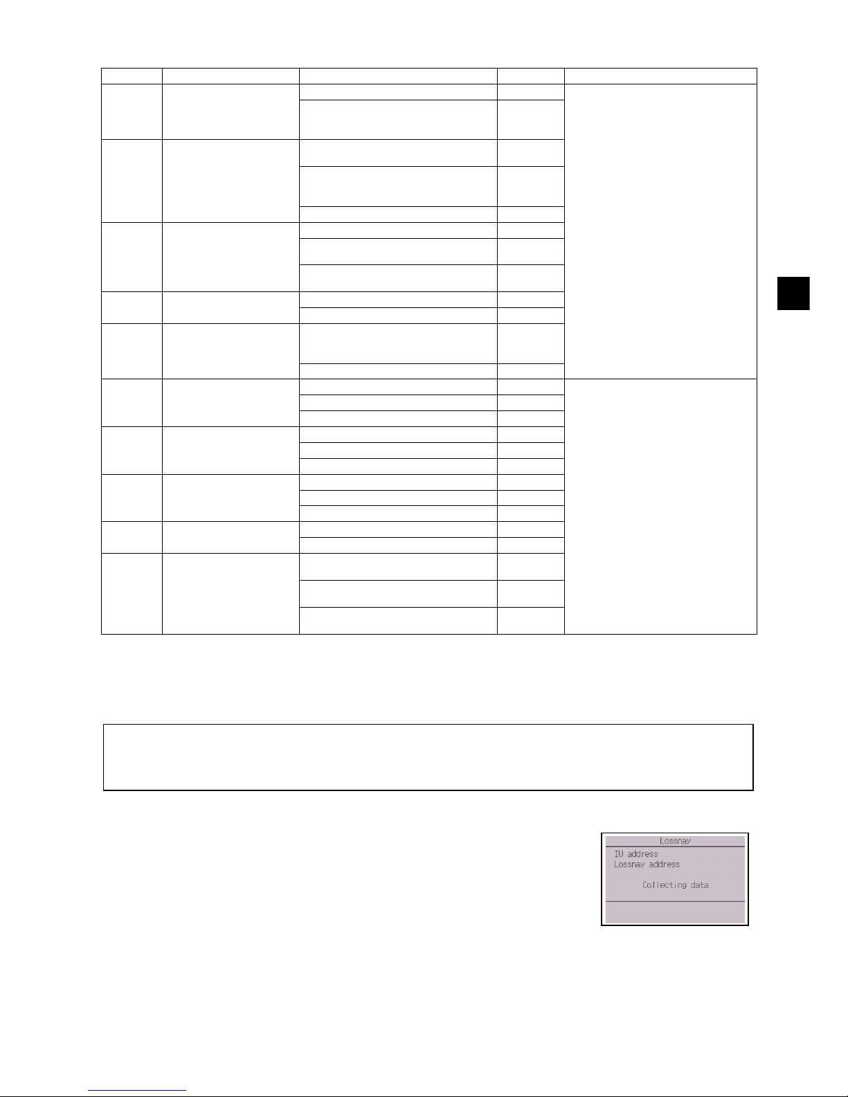
(5) LOSSNAY setting (CITY MULTI only)
This setting is required only when the operation of CITY MULTI units is interlocked with LOSSNAY
units. This setting is not available for the Mr. SLIM units. Interlock settings can be made for the indoor
unit to which the remote controller is connected. (They can also be confirmed or deleted.)
[Button operation]
Mode No. Mode Settings Setting No. Unit numbers
01 Automatic recovery after
power failure
Disable 1 Set “Grp.” for the Unit number.
These settings apply to all the
connected indoor units.
Enable (Four minutes of standby time
is required after the restoration of
power.)
2
02 Thermistor selection
(indoor temperature
detection)
Average temperature reading of the
indoor units in operation
1
Thermistor on the indoor unit to which
the remote controller is connected
(fixed)
2
Built-in sensor on the remote controller 3
03 LOSSNAY connection Not connected 1
Connected (without outdoor air intake
by the indoor units )
2
Connected (with outdoor air intake by
the indoor units )
3
04 Power voltage 240 V 1
220 V, 230 V 2
05 Auto mode Enable (Automatically the unit
achieves effective energy saving
operation.)
1
Disable 2
07 Filter sign 100 hours 1 Set “1, 2, 3, 4, or All” for the Unit
number.
These settings apply to each indoor
unit.
·If “1, 2, 3, or 4” is set for the Unit
number, the settings apply only to
the specified indoor unit regardless
of the number of connected indoor
units (one through four units).
·If “All” is set for the Unit number, the
settings apply to all the connected
indoor units regardless of the
number of connected indoor units
(one through four units).
2500 hours 2
Not displayed 3
08 Fan speed Silent mode (or standard) 1
Standard (or High ceiling 1) 2
High ceiling (or High ceiling 2) 3
09 Outlet 4 directional 1
3 directional 2
2 directional 3
10 Optional parts
(High-efficiency filter)
No 1
Ye s 2
11 Vane No vanes (or the vane setting No.3 is
effective.)
1
Equipped with vanes (The vane
setting No.1 is effective.)
2
Equipped with vanes (The vane
setting No.2 is effective.)
3
Note:
· Use the centralized controller to make the settings if it is connected.
· To interlock the operation of the indoor units with the LOSSNAY units, be sure to interlock the addresses of ALL
indoor units in the group and that of the LOSSNAY unit.
1 When “Lossnay” on the Settings menu is selected, the remote controller
will automatically begin searching for the registered LOSSNAY
addresses of the currently connected indoor unit.
Page 26
– 26 –
GB
2 When the search is completed, the smallest address of the indoor units
that are connected to the remote controller and the address of the
interlocked LOSSNAY unit will appear. “--” will appear if no LOSSNAY
unit is interlocked with the indoor units.
If no settings need to be made, press the RETURN button to go back to
the Settings menu.
To make LOSSNAY interlock setting
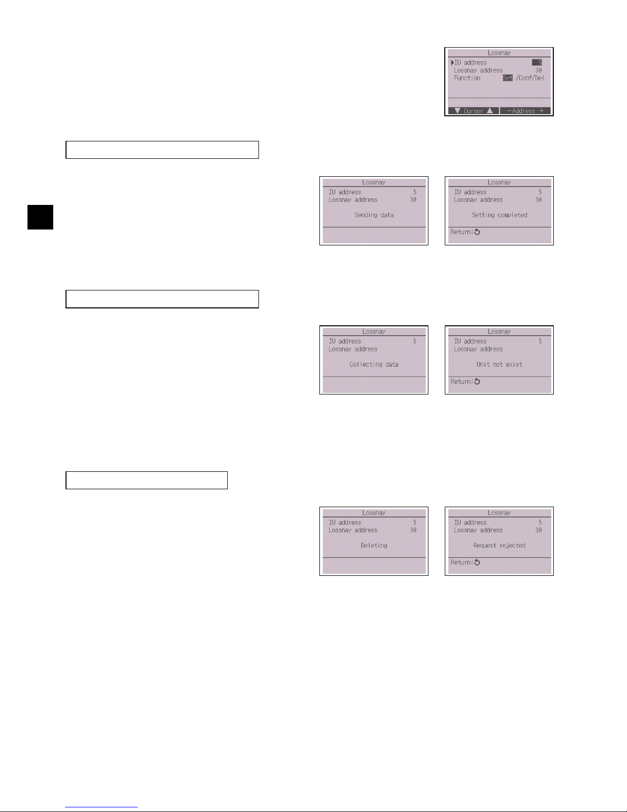
3 Enter the addresses of the indoor unit and the
LOSSNAY unit to be interlocked, with the F1
through F4 buttons, select “Set” in the
“Function”, and press the SELECT button to
save the settings. “Sending data” will appear
on the screen. If the setting is successfully
completed, “Setting completed” will appear.
To search for the LOSSNAY address
4 Enter the address of the indoor unit to which
the remote controller is connected, select
“Conf” in the “Function”, and press the
SELECT button. “Collecting data” will appear
on the screen. If the signal is received
correctly, the indoor unit address and
LOSSNAY address will appear. “--” will
appear when no LOSSNAY unit is found.
“Unit not exist” will appear if no indoor units
that are correspond to the entered address
are found.
To delete the interlock setting
5 To delete the interlocked setting between
LOSSNAY unit and the indoor units to which
the remote controller is connected, enter the
indoor unit address and LOSSNAY address
with the F1 through F4 buttons, select “Del.”
in the “Function”, and press the SELECT
button. “Deleting” will appear. The screen will
return to the search result screen if the
deletion is successfully completed. “Unit not
exist” will appear if no indoor units that are
correspond to the entered address are found.
If deletion fails, “Request rejected” will
appear on the screen.
Page 27
– 27 –
GB
(6) Check
[Button operation]
(7) Diagnostic function
Error history of each unit can be checked via the remote controller.
[Button operation]
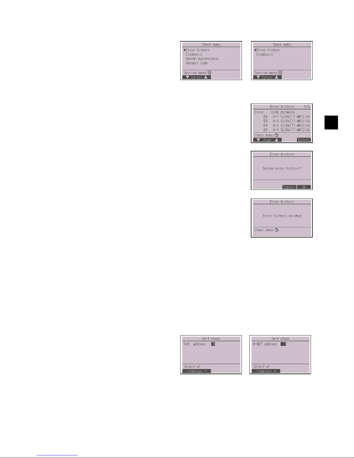
Select “Check” on the Service menu to bring up
the Check menu screen.
The type of menu that appears depends on the
type of indoor units that are connected (CITY
MULTI or Mr. SLIM).
(When CITY MULTI is connected, only “Error
history” will appear in the menu.)
<Mr. SLIM> <CITY MULTI>
1 Error history
Select “Error history” from the Check menu, and press the SELECT
button to view up to 16 error history records. Four records are shown
per page, and the top record on the first page indicates the latest error
record.
[Deleting the error history]
To delete the error history, press the F4 button (Delete) on the screen
that shows error history. A confirmation screen will appear asking if you
want to delete the error history.
Press the F4 button (OK) to delete the error history.
“Error history deleted” will appear on the screen. Press the RETURN
button to go back to the Check menu screen.
2 Other options in the Check menu (Mr. SLIM only)
The following options are also available on the Mr. SLIM units in the Check menu.
• Smooth maintenance
• Request code
These options are available only on the Mr. SLIM units. Refer to the indoor unit Installation Manual
for details.
1 Select “Self check” from the Diagnosis menu,
and press the SELECT button to view the
Self check screen.
2 With the F1 or F2 button, enter the refrigerant
address (Mr. SLIM) or the M-NET address
(CITY MULTI), and press the SELECT
button.
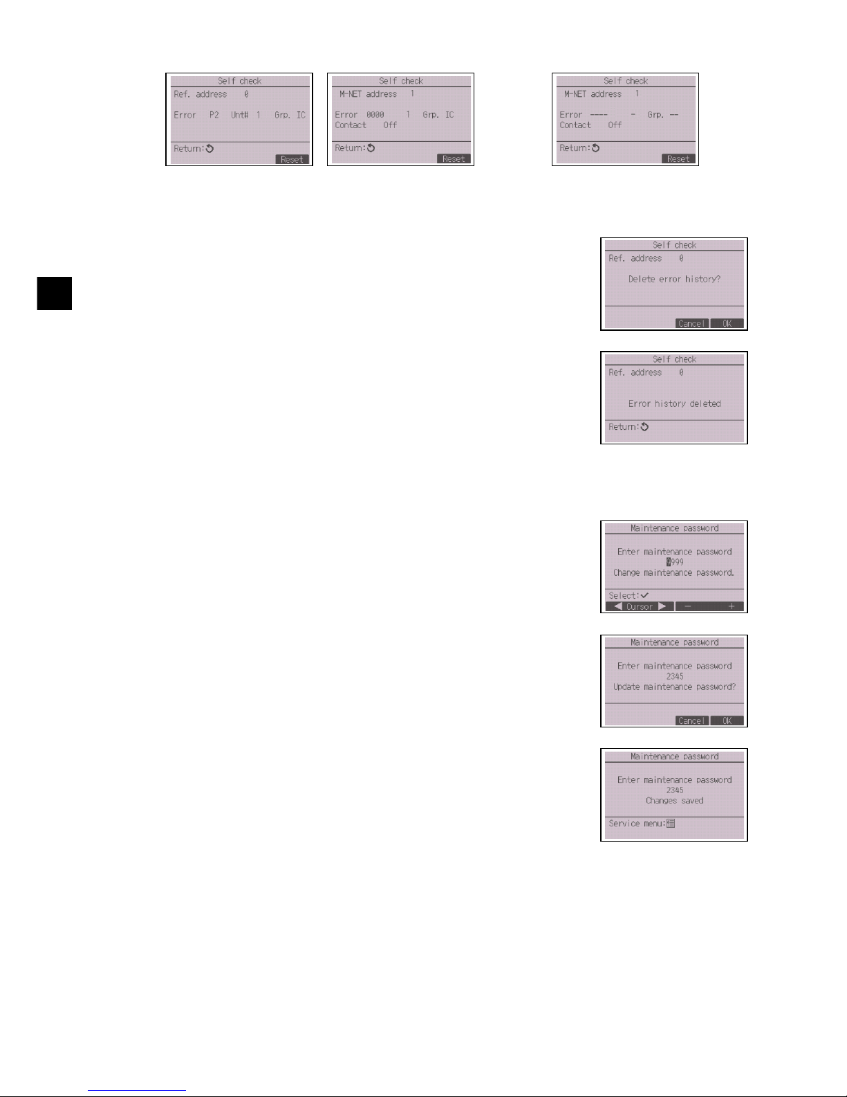
3 Error code, unit number, attribute, and indoor
unit demand signal ON/OFF status at the
contact (CITY MULTI only) will appear. “-” will
appear if no error history is available.
<Mr. SLIM> <CITY MULTI>
Page 28
– 28 –
GB
[Resetting the error history]
(8) Changing the maintenance password
[Button operation]
<Mr. SLIM> <CITY MULTI>
When there is no error history
1 Press the F4 button (Reset) on the screen that shows the error history.
A confirmation screen will appear asking if you want to delete the error
history.
2 Press the F4 button (OK) to delete the error history. If deletion fails,
“Request rejected” will appear, and “Unit not exist” will appear if no
indoor units that are correspond to the entered address are found.
1 Select “Maintenance password” on the Others menu, and press the
SELECT button to bring up the screen to enter a new password.
2 Move the cursor to the digit you want to change with the F1 or F2
button, and set each digit to the desired number (0 through 9) with the
F3 or F4 button.
3 Press the SELECT button to save the new password.
4 A confirmation screen will appear asking if you want to change the
maintenance password. Press the F4 button (OK) to save the change.
Press the F3 button (Cancel) to cancel the change.
5 “Changes saved” will appear when the password is updated.
6 Press the MENU button to return to the Service menu or press the
RETURN button to go back to the “Maintenance password” screen.
Page 29
– 29 –
GB
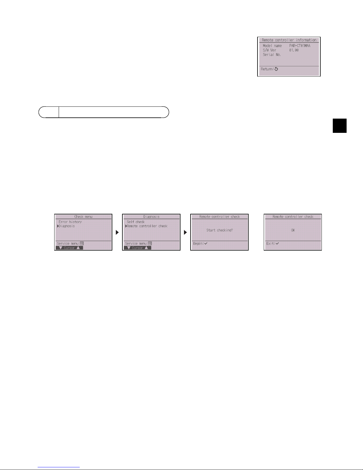
(9) Remote controller information
When the remote controller does not work properly, use the remote controller checking function to
troubleshoot the problem.
(1) Check the remote controller display and see if anything is displayed (including lines). Nothing will
appear on the remote controller display if the correct voltage (8.5-12 VDC) is not supplied to the
remote controller. If this is the case, check the remote controller wiring and indoor units.
[Button operation]
OK: No problems are found with the remote controller. Check other parts for problems.
E3, 6832: There is noise on the transmission line, or the indoor unit or another remote controller is faulty. Check
the transmission line and the other remote controllers.
NG (ALL0, ALL1): Send-receive circuit fault. Remote controller needs replacing.
ERC: The number of data errors is the discrepancy between the number of bits in the data transmitted from the
remote controller and that of the data that was actually transmitted over the transmission line. If data errors
are found, check the transmission line for external noise interference.
The following information of the remote controller in use can be checked.
• Model name
• Software version
• Serial number
[Button operation]
1 Select “Others” from the Service menu.
2 Select “Remote controller information”.
12 Remote controller check
1 Select “Remote controller check” from the Diagnosis menu, and press the SELECT button to start
the remote controller check and see the check results. To cancel the remote controller check and
exit the Remote controller check menu screen, press the MENU or the RETURN button. The
remote controller will not reboot itself.
Select “Remote
controller check”.
Remote controller check
results screen
2 If the SELECT button is pressed after the remote controller check results are displayed, remote
controller check will end, and the remote controller will automatically reboot itself.
Page 30

– 30 –
GB
Page 31

– 1 –
F
Ce manuel d’installation décrit comment installer la Télécommande tactile MA en vue de son utilisation
avec le Système de climatisation de bâtiment Mitsubishi, les unités intérieures de climatiseurs CITY
MULTI de type extension directe (type « -A » et ultérieurs), et les climatiseurs autonomes Mitsubishi
Mr. SLIM.
Assurez-vous de lire ce manuel d’installation et les fichiers sur le CD-ROM fourni avec la
Télécommande tactile avant de procéder à l’installation. Le non-respect de cette prescription peut
entraîner des dommages pour les appareils.
Reportez-vous aux fichiers sur le CD-ROM fourni avec la Télécommande tactile pour les informations
qui ne figurent pas dans ce livret. Si les fichiers sont illisibles, veuillez contacter votre revendeur.
Pour des informations sur le câblage et l’installation des climatiseurs, reportez-vous au manuel
d’installation.
Après l’installation, remettez ce manuel aux utilisateurs.
• Lisez attentivement les consignes de sécurité ci-après avant de procéder à l’installation.
• Respectez scrupuleusement ces consignes pour assurer votre sécurité.
• Après avoir lu ce manuel, remettez-le à l’utilisateur final pour qu’il puisse le consulter en cas de
besoin.
• Conservez ce manuel pour pouvoir le consulter en cas de besoin. Il convient que ce manuel soit
accessible aux personnes chargées de réparer ou de déplacer le contrôleur. Assurez-vous que le
manuel est bien transmis à tout futur utilisateur final.
1 Consignes de sécurité
AVERTISSEMENT
Signale un risque de blessure grave, voire mortelle.
ATTENTION
Signale un risque de blessure grave ou de dommage matériel.
Seul un personnel qualifié est autorisé à réaliser les travaux électriques.
Système de contrôle CITY MULTI
et Climatiseurs Mitsubishi Mr. SLIM
Télécommande tactile MA
PAR-CT01MAA-PB
PAR-CT01MAA-SB
PAR-CT01MAA-S
PAR-CT01MAR-PB
PAR-CT01MAR-SB
Manuel d’installation
WT08580X01
F
Pour distribution aux distributeurs et aux sous-traitants
<Traduction des instructions d’origine>
Page 32

– 2 –
F
AVERTISSEMENT
ATTENTION
AVERTISSEMENT
ATTENTION
Précautions générales
Précautions pendant l’installation
N’installez pas l’unité en un endroit où se trouvent de
grandes quantités d’huile, de vapeur, de solvants
organiques ou de gaz corrosifs tels du gaz sulfurique ou
encore là où sont fréquemment utilisés des aérosols ou des
solutions acides/alcalines. Ces substances peuvent affecter
les performances de l’unité ou provoquer la corrosion de
certains de ses composants, ce qui peut donner lieu à des
défauts de fonctionnement, des dégagements de fumée ou
même une électrocution ou un incendie.
Ne lavez pas le contrôleur avec de l’eau ou tout autre
liquide afin de prévenir tout risque de court-circuit, de
fuite électrique, d’électrocution, de dysfonctionnement,
de fumée ou d’incendie.
N’utilisez pas les commutateurs/boutons ou d’autres
parties électriques avec les mains mouillées afin de
prévenir tout risque d’électrocution, de
dysfonctionnement, de fumée ou d’incendie.
Pour éviter tout risque de blessure ou d’électrocution,
éteignez le contrôleur et coupez l’alimentation
électrique avant de le nettoyer, de l’examiner ou avant
toute opération d’entretien de celui-ci.
Pour éviter tout risque de lésion ou d’électrocution,
éteignez le contrôleur et couvrez-le avant de pulvériser
un quelconque produit chimique dans l’environnement
de celui-ci.
Pour prévenir tout risque de blessure, tenez les enfants
éloignés pendant l’installation, l’inspection ou la
réparation de l’unité.
Installez correctement toutes les protections requises
pour protéger le contrôleur contre l’humidité et la
poussière. L’accumulation de poussière et d’eau peut
provoquer des électrocutions, de la fumée ou un
incendie.
Ne touchez pas l’écran tactile, les commutateurs ou les
boutons avec un objet pointu ou tranchant afin de prévenir
tout risque d’électrocution ou de dysfonctionnement.
Pour prévenir tout risque d’endommager le contrôleur,
ne pulvérisez pas d’insecticide ou tout autre aérosol
inflammable directement dessus.
Évitez le contact avec les bords tranchants de
certaines parties afin de prévenir tout risque de
blessure et d’électrocution.
Pour prévenir tout risque de blessure, portez un
équipement de protection lors de toute intervention sur
le contrôleur.
Contactez votre revendeur pour la mise au rebut du
contrôleur.
N’exercez pas une force excessive sur les parties en
verre pour éviter qu’elles se brisent et provoquent des
blessures.
Pour prévenir tout risque d’incendie ou d’explosion, ne
placez pas de matériaux inflammables et ne pulvérisez
pas de substances inflammables dans l’environnement
du contrôleur.
N’installez pas l’unité dans un endroit où peut se
produire une fuite de gaz inflammable.
Si du gaz inflammable s’accumule autour de l’unité, il
peut s’enflammer et provoquer un incendie ou une
explosion.
Prenez des mesures de sécurité appropriées contre
les tremblements de terre pour éviter que le contrôleur
provoque des blessures.
Mettez les matériels d’emballage au rebut
conformément à la réglementation. Les enfants
risquent de s’étouffer avec les sachets en plastique.
Pour prévenir tout risque de blessure, installez le
contrôleur sur une surface plane suffisamment solide
pour supporter son poids.
Pour prévenir tout risque de court-circuit, de fuite
électrique, d’électrocution, de dysfonctionnement, de
fumée ou d’incendie, n’installez pas le contrôleur en un
endroit exposé à l’eau ou à la condensation.
Le contrôleur doit être installé par du personnel qualifié
en suivant les instructions décrites dans le Manuel
d’installation.
Une installation incorrecte peut être la cause d’une
électrocution ou d’un incendie.
Installez le boîtier supérieur dans le boîtier inférieur
jusqu’à ce que vous entendiez un clic
d’enclenchement.
Quand vous fixez le couvercle et le boîtier supérieur au
boîtier inférieur, poussez-les jusqu’à ce qu’ils
s’enclenchent en place. S’ils ne sont pas correctement
verrouillés en place, ils peuvent tomber, et provoquer
des blessures, des dommages au contrôleur, ou des
dysfonctionnements.
Page 33

– 3 –
F
AVERTISSEMENT
ATTENTION
AVERTISSEMENT
ATTENTION
Précautions pendant le câblage
Précautions pour le déplacement ou la réparation du contrôleur
Pour prévenir tout risque de dommage au contrôleur,
de dysfonctionnement, de dégagement de fumée ou
d’incendie, ne branchez pas le câble d’alimentation au
bornier des signaux.
Fixez correctement les câbles en place et laissez
assez de mou aux câbles pour ne pas exercer de
contrainte sur les bornes. Des câbles mal connectés
peuvent se casser, surchauffer, et provoquer de la
fumée ou un incendie.
Pour prévenir tout risque de blessure et
d’électrocution, coupez l’alimentation générale avant
d’effectuer un travail électrique.
Tous les travaux électriques doivent être effectués par
un électricien qualifié conformément à la
réglementation et aux normes locales et en suivant les
instructions décrites dans le Manuel d’installation.
Pour prévenir tout risque d’électrocution, installez un
disjoncteur ainsi qu’un interrupteur à courant
différentiel résiduel sur l’alimentation électrique.
Pour prévenir tout risque d’électrocution, de fumée ou
d’incendie, installez un disjoncteur pour chaque
contrôleur.
Utilisez des disjoncteurs et fusibles correctement
calibrés (disjoncteur, commutateur local <commutateur
+ fusible>, disjoncteur sans fusible).
Les disjoncteurs à capacité de coupure supérieure à
celle spécifiée peuvent provoquer un
dysfonctionnement, une électrocution, un dégagement
de fumée ou un incendie.
Pour prévenir tout risque de fuite électrique, de
surchauffe, de dégagement de fumée ou d’incendie,
utilisez des câbles de section appropriée pour le
courant nominal spécifié.
Une mise à la terre appropriée doit être assurée par
un électricien agréé.
Ne raccordez pas le câble de mise à la terre à une
conduite de gaz, à une arrivée d’eau, au paratonnerre
ou au câble téléphonique.
Une mise à la terre incorrecte peut être la cause d’une
électrocution, d’un dégagement de fumée, d’un
incendie ou d’un dysfonctionnement en raison
d’interférences électromagnétiques.
Pour réduire les risques d’électrocution, de court-circuit
ou de dysfonctionnement, retirez toutes les chutes de
fil et de gaine du bornier.
Pour prévenir tout risque de court-circuit, de fuite
électrique, d’électrocution ou de dysfonctionnement,
ne laissez pas les câbles entrer en contact avec les
bords vifs du contrôleur.
Bouchez soigneusement les trous d’accès des câbles
avec du mastic pour éviter toute condensation,
infiltration d’eau et d’insectes qui pourrait provoquer
des dysfonctionnements, une électrocution ou un
incendie. L’infiltration d’eau et la formation de
condensation à l’intérieur de l’unité peuvent
endommager la carte de circuit imprimé.
Seul un personnel qualifié doit être autorisé à réparer
le contrôleur ou à le changer de place.
N’essayez pas de démonter ou de modifier le
contrôleur vous-même.
Une installation ou une réparation non conforme peut
entraîner des blessures, une électrocution ou un
incendie.
Pour réduire les risques d’électrocution, de court-circuit
ou de dysfonctionnement, retirez toutes les chutes de
fil et de gaine du bornier.
Page 34

– 4 –
F
Précautions supplémentaires
Pour prévenir tout dommage à l’unité, utilisez des
outils appropriés pour son installation, son inspection
ou sa réparation.
Ce contrôleur est exclusivement destiné à être utilisé
avec le Système de gestion d’immeuble de Mitsubishi
Electric.
L’utilisation de ce contrôleur avec d’autres systèmes
ou à d’autres fins peut entraîner des
dysfonctionnements.
N’utilisez pas de benzène, de diluant ou d’abrasif
chimique pour nettoyer le contrôleur afin d’éviter de le
décolorer.
Pour nettoyer le contrôleur, essuyez-le avec un chiffon
doux imbibé d’un mélange d’eau et d’un détergent
doux, rincez les restes de détergent avec un chiffon
humide, puis essuyez l’eau avec un chiffon sec.
Protégez le contrôleur contre l’électricité statique pour
éviter de l’endommager.
Prenez des dispositions appropriées contre les
interférences électromagnétiques lorsque les
climatiseurs sont installés dans des hôpitaux ou à
proximité d’équipements de radiocommunication.
Les onduleurs ainsi que les équipements médicaux à
haute fréquence ou de communication sans fil et les
générateurs d’énergie peuvent être la cause de
dysfonctionnements du système de climatisation. Le
système de climatisation peut également affecter le
bon fonctionnement de ces types d’équipement en
créant du bruit électrique.
Pour prévenir tout dysfonctionnement, n’attachez pas
les câbles d’alimentation et de signaux ensemble et
faites-les passer dans des chemins de câbles
différents.
Laissez le circuit imprimé et son film de protection sur
le boîtier.
Ne serrez pas trop les vis pour éviter d’endommager le
contrôleur.
Utilisez un tournevis à tête plate avec une lame de
3-5 mm (1/8-7/32 pouce).
Ne tournez pas avec force le tournevis à tête plate en
le rentrant dans la fente de verrouillage.
Pour prévenir toute déformation et dysfonctionnement,
n’installez par la télécommande en un endroit
directement exposé au soleil ou là où la température
peut dépasser 40°C (104°F) ou chuter au-dessous de
0°C (32°F).
N’installez pas le contrôleur sur la porte du panneau
de commande. Des vibrations ou des chocs subis par
le contrôleur pourraient l’endommager ou le faire
tomber.
Fixez le câble à l’aide d’un serre-fils.
N’utilisez pas de bornes à sertir pour raccorder les
câbles au bornier.
Ce type de borne risque d’entrer en contact avec le
circuit imprimé et de provoquer des
dysfonctionnements, voire même d’endommager le
cache du contrôleur.
Après avoir raccordé le connecteur, installez le boîtier
supérieur de manière adéquate.
Si le câble électrique est endommagé, il doit être
remplacé par le fabricant, son agent de service ou une
personne de qualification similaire afin d’éviter tout
risque.
Cet appareil n’est pas destiné à être utilisé par des
personnes (enfants inclus) dont les capacités
mentales, sensorielles ou physiques sont réduites, ou
qui ne disposent pas de l’expérience et des
connaissances requises, sauf si une personne
responsable de leur sécurité assure leur surveillance
ou leur formation dans le cadre de l’utilisation de
l’appareil.
Les enfants doivent être surveillés de manière à ce
qu’ils ne puissent pas jouer avec l’appareil.
Cet appareil est prévu pour être utilisé par des
utilisateurs experts ou formés dans les magasins,
l’industrie légère et les fermes ou pour une utilisation
commerciale par des personnes non initiées.
Pour prévenir tout dommage au contrôleur, utilisez des
outils appropriés pour son installation, son inspection
ou sa réparation.
Pour éviter des dysfonctionnements, ne retirez pas le
film de protection ou le circuit imprimé du boîtier.
N’installez pas le contrôleur sur la porte du panneau de
commande. Des vibrations ou des chocs subis par le
contrôleur pourraient l’endommager ou le faire tomber.
Ne percez pas de trous dans le cache pour éviter
d’endommager le contrôleur.
Maintenez les câbles en place avec des serre-fils pour
éviter qu’une force inappropriée ne soit appliquée au
bornier et provoque des ruptures de câbles.
Page 35

– 5 –
F
Votre ordinateur doit satisfaire aux exigences de configuration suivantes pour exécuter le logiciel de
navigation des manuels.
[Ordinateur] Compatible PC/AT
[Processeur] Core2 Duo 1,66 GHz minimum (Core2 Duo 1,86 GHz ou supérieur recommandé)
Pentium D 1,7 GHz minimum (Pentium D 3,0 GHz ou supérieur recommandé)
Pentium M 1,7 GHz minimum (Pentium M 2,0 GHz ou supérieur recommandé)
Pentium 4 2,4 GHz minimum (Pentium 4 2,8 GHz ou supérieur recommandé)
* Un processeur Core2 Duo ou supérieur est requis pour exécuter le logiciel de
navigation des manuels sous Windows Vista ou une version ultérieure.
[RAM] Windows Vista ou version ultérieure : 1 Go minimum (2 Go minimum recommandé)
Windows XP : 512 Mo minimum (1 Go minimum recommandé)
[Espace disque] 1 Go minimum (espace disponible)
* Windows Vista ou version ultérieure : espace disponible sur le lecteur contenant
le dossier Document
* Windows XP : espace disponible sur le lecteur contenant le dossier Mes
documents
[Résolution] Affichage 800 × 600 SVGA minimum
[Système d’exploitation] Windows8/Pro/Enterprise (version Pro recommandée)
Windows7 Ultimate/Enterprise/Professional/Home Premium Service Pack1
(version Professional recommandée)
Windows Vista Ultimate/Business/Home Basic Service Pack1 (version
Business recommandée)
Windows XP Professional/Home Edition Service Pack2 ou Service Pack3
(version Professional recommandée)
[Logiciels requis] Windows8 : Adobe Reader 11.0.2 ou version ultérieure (Windows Reader,
installé par défaut sous Windows8, ne peut pas être utilisé.)
Windows7 : Adobe Reader 10.1.0 ou version ultérieure
Windows XP et Windows Vista : Adobe Reader 8.1.3 ou version ultérieure
* Logiciels d’affichage de fichiers PDF
-----------------------------------------------------------------------------------------------------------------------------------« Windows », « Windows XP », « Windows Vista », « Windows7 » et « Windows8 » sont des
marques déposées de Microsoft Corporation.
« Adobe Reader » et « Adobe Acrobat » sont des marques déposées d’Adobe Systems Incorporated.
« Core2 Duo » et « Pentium » sont des marques déposées d’Intel Corporation.
------------------------------------------------------------------------------------------------------------------------------------
2 Configuration requise
AVERTISSEMENT
Le CD-ROM fourni avec l’unité ne peut être lu qu’à partir d’un lecteur de
CD ou de DVD. N’essayez pas de lire ce CD-ROM sur un lecteur de CD
audio car ceci pourrait endommager vos haut-parleurs et/ou porter
atteinte à votre audition.
Page 36

– 6 –
F
Les pièces suivantes sont incluses dans le coffret.
(1) Pièces à fournir sur le site
Les pièces suivantes sont des pièces à fournir sur le site.
(2) Outils à fournir sur le site
• Tournevis à tête plate (largeur : 3-5 mm (1/8-7/32 pouce))
•Pince
• Outillage divers
3 Nomenclature des composants et pièces fournies
*3 Filetage métrique ISO
*4 Le câble de la télécommande n’est pas inclus.
4 Pièces à fournir sur le site/Outils nécessaires
Nomenclature Qté Remarques
Boîtier de connexion simple 1 Non nécessaire pour installation directe sur le mur
Conduit métallique à paroi mince Nécessaire
Écrou de blocage et presse-étoupe Nécessaire
Chemin de câble Nécessaire
Nécessaire pour faire passer le câble de la télécommande
le long d’un mur
Mastic Raisonnable
Boulon d’ancrage à gaine
d’expansion
Nécessaire
Câble de la télécommande
(Utilisez un câble gainé à deux
âmes de 0,3 mm² (AWG22).)
Nécessaire
Nomenclature Qté Apparence
Télécommande (boîtier supérieur) 1 Figure de droite *1
Télécommande (boîtier inférieur) 1 Figure de droite *2
Vis à tête ronde fente en croix M4x30 2 *3
Vis à bois 4,1x16
(pour montage direct sur le mur)
2*3
Manuel simplifié 1
CD-ROM (ce manuel)
Manuel d’utilisation et Manuel
d’installation
1
Boîtier inférieur *2
Boîtier supérieur *1
h
16 (5/8) 16 (5/8)
25 (1)
25 (1)
102 (4)
54 (2-1/8)
20
(13/16)
10
(3/8)
44 (1-3/4)
(3-3/8±1/32)
ø6 (1/4DE)
20 (13/16)
6
(1/4)
ø6 (1/4DE)
20 (13/16)
Boîtier de
connexion
unité : mm (po)
1,5 (1/16) ou inférieur
83,5 ± 0,4
Page 37

– 7 –
F
Le câblage varie selon que la télécommande est reliée au système de contrôle CITY MULTI
(type « -A » et ultérieurs) ou raccordé au climatiseur Mitsubishi Mr. SLIM (type de commande A). Le
câblage dépend également de la configuration du système. Vérifiez le système utilisé.
1. Raccordement au système de contrôle CITY MULTI
Les chiffres (1) à (4) sur la figure correspondent aux éléments (1) à (4) du descriptif suivant.
(1) Câblage de la télécommande
• Effectuez un branchement au bornier de la Télécommande MA (TB15) sur l’unité intérieure.
• Il n’y a pas de polarité à suivre pour le bornier. Effectuez un branchement au bornier sur le
dessous de la télécommande.
(2) Fonctionnement de groupe (Groupes 03 et 04 ci-dessus)
• Interconnectez le bornier de la Télécommande MA (TB15) des unités intérieures que vous
souhaitez faire fonctionner en tant que groupe et raccordez la Télécommande MA à ce point.
• Si la télécommande est associée au contrôleur de système comme le montre la figure ci-dessus,
un réglage de groupe est alors nécessaire au niveau du contrôleur de système (contrôleur central
sur la figure ci-dessus).
(3) Nombre de contrôleurs à distance pouvant être raccordés
• Une seule télécommande peut être raccordée au groupe composé d’unités intérieures.
• La Télécommande tactile MA peut être raccordée à d’autres contrôleurs du même type.
(4) Pour une synchronisation avec une unité de traitement LOSSNAY ou OA, effectuez les réglages
suivants à l’aide de la télécommande. (Pour savoir comment établir une synchronisation, veuillez
consulter la section 11 « Menu Service » (5) « Réglage LOSSNAY ».)
Configurez l’adresse de l’unité de traitement LOSSNAY ou OA ainsi que celle de l’ensemble des
unités intérieures que vous souhaitez synchroniser.
(5) Longueur totale du câblage de la télécommande
• Le câblage de la Télécommande tactile MA peut s’étendre jusqu’à 70 m (229 pieds).
5 Câblage de la ligne de transmission
Raccordement à
TB15 sur l’unité
intérieure.
a Unité extérieure
b Unité intérieure
c LOSSNAY ou
unité de traitement OA
d Télécommande tactile
e Contrôleur central
f Bloc d’alimentation
électrique pour la ligne de
transmission
TB5 TB15
TB5 TB15
bb
TB5 TB15
c
TB5 TB15
b
TB5 TB15
b
TB5 TB15
b
TB5 TB15
b
TB7 TB3
TB5 TB15
TB5 TB15
TB7 TB3
(1)
(1)
(3)
(3)
(3)
(3)
(2)
(2)
(2)
(4)
(1)
(1)
a
a
dd d
d
bb
e
f
Adresse = 51
Adresse = 01 Adresse = 02
Adresse = 55
Adresse = 08
Adresse = 07
Adresse = 03
Adresse = 04 Adresse = 09
Adresse = 06
Adresse = 05
Groupe 01 Groupe 02 Groupe 03
Groupe 04
REMARQUE : lors de la synchronisation de la Télécommande MA avec une unité de
traitement LOSSNAY ou OA, configurez toujours l’adresse de l’ensemble des
unités intérieures du groupe ainsi que celle de l’unité de traitement LOSSNAY
ou OA.
Page 38

– 8 –
F
2. Raccordement au climatiseur Mitsubishi Mr. SLIM
Le câblage de la télécommande dépend de la configuration du système. Vérifiez la configuration du
système. Procédez au câblage de la télécommande comme indiqué dans l’exemple ci-dessous.
Les chiffres (1) à (3) de la figure correspondent aux éléments (1) à (3) du descriptif suivant.
[1] Raccordement de la télécommande pour chaque système réfrigérant (Standard 1:1, double
simultané, triple simultané, quadruple simultané)
[2] Lors de regroupements par système réfrigérant
* Configurez l’adresse du réfrigérant à l’aide des commutateurs dip de l’unité extérieure. (Pour plus
d’informations, veuillez vous reporter au manuel d’installation de l’unité extérieure.)
* Toutes les unités intérieures entourées de la manière suivante sont contrôlées en tant que
groupe.
(1) Câblage de la télécommande
• Effectuez un branchement à l’unité intérieure TB5 (bornier de la télécommande). (Il n’y a pas de
polarité à suivre pour le bornier.)
• Pour un type multi simultané, raccordez toujours la télécommande à l’unité intérieure disposant
de la plupart des fonctions (vitesse du vent, vanne, volet, etc.) lorsque vous mélangez différents
types d’unités intérieures.
(2) Lors de regroupements par système réfrigérant
• Établissez des groupes à l’aide du câblage de la télécommande. Raccordez la télécommande à
n’importe quelle unité intérieure de chacun des systèmes réfrigérants que vous souhaitez
regrouper.
• Lorsque vous mélangez différents types d’unités intérieures dans un même groupe, raccordez
toujours l’unité extérieure à l’unité intérieure disposant de la plupart des fonctions (vitesse du
vent, vanne, volet, etc.), l’unité Principale (adresse du réfrigérant = 00). Par ailleurs, si l’unité
Principale est le type multi simultané, veillez à toujours remplir les conditions énoncées au
premier point (1).
• La Télécommande tactile MA peut commander jusqu’à 16 systèmes réfrigérants en un seul
groupe.
(3) Une seule télécommande peut être raccordée à chaque groupe. La télécommande ne peut être
associée à d’autres contrôleurs du même type.
Raccordement à TB5 sur
l’unité intérieure.
a Unité extérieure
b Unité intérieure
d Télécommande tactile
(1)
TB5
TB4
TB1
TB4
(3)
a
bb
d
Adresse du
réfrigérant = 00
Double simultané
TB4
TB4
TB4
TB4
TB4TB4
TB1 TB1 TB1
TB5
TB5
TB5
(2)
(1)
(3)
(2)
aa a
bbbbbb
d
Standard 1:1 Double simultané
Triple simultané
Adresse du
réfrigérant = 01
(Sec.)
Adresse du
réfrigérant = 00
(Principal)
Adresse du
réfrigérant = 02
(Sec.)
Page 39

– 9 –
F
(4) Longueur totale du câblage de la télécommande
• Le câblage de la Télécommande tactile MA peut s’étendre jusqu’à 150 m (492 pieds).
Cette télécommande est prévue pour une installation murale. Il peut être installé dans le boîtier de
connexion ou directement sur le mur. Lorsque vous effectuez une installation directe sur un mur, les
fils peuvent être passés par l’arrière ou sur le dessus de la télécommande.
(1) Choix d’un site d’installation
Installez la télécommande (boîtier de connexion) sur le site dans un endroit satisfaisant aux
conditions suivantes.
(a) Pour une connexion à l’unité intérieure avec un panneau Auto descendant, un endroit où
quelqu’un puisse vérifier le fonctionnement du panneau Auto descendant de l’unité intérieure
pendant qu’il utilise la télécommande. (Reportez-vous au manuel d’utilisation de l’unité intérieure
pour savoir comment utiliser le panneau Auto descendant.)
(b) Une surface plane
(c)
Un endroit où la télécommande peut mesurer la température interne exacte
Les capteurs de surveillance de la température intérieure sont situés sur l’unité intérieure et sur la
télécommande. Quand la température est surveillée avec le capteur de la télécommande, le capteur
intégré à la télécommande surveille la température de la pièce. Lorsque vous utilisez le capteur de la
télécommande, suivez les instructions ci-dessous.
• Pour surveiller la température intérieure exacte, installez la télécommande à l’écart de la lumière
directe du soleil, des sources de chaleur, et de la sortie d’air du climatiseur.
• Installez la télécommande dans un endroit qui permette au capteur de mesurer une température
représentative de celle de la pièce.
• Installez la télécommande au endroit ou aucun fil ne passe à proximité du capteur de température
du contrôleur. (Si des fils passent à proximité, le capteur ne peut pas mesurer exactement la
température intérieure.)
ATTENTION - Le câblage ne peut être raccordé au bornier TB5 de l’unité intérieure du
même système réfrigérant. Si c’est le cas, le système ne fonctionnera pas
correctement.
- Les télécommandes tactiles ne peuvent être reliées entre eux. Un seul
câble peut être raccordé au bornier de la télécommande.
a Unité extérieure
b Unité intérieure
d Télécommande tactile
6 Installation
d
d
TB4
TB4
TB4
TB4
TB4
TB4
TB1
TB1 TB1
TB1
TB5
TB5
TB5
TB5 TB5 TB5
a
bbb bbb
d
aa a
Adresse du
réfrigérant = 00
Adresse du
réfrigérant = 00
Adresse du
réfrigérant = 01
Adresse du
réfrigérant = 00
Double simultané Standard 1:1 Double simultané Standard 1:1
■ Des écarts entre la température intérieure mesurée sur le mur et la température
intérieure effective peuvent être constatés.
Si l’une des conditions suivantes se produit, il est recommandé d’utiliser le capteur de l’unité
intérieure.
• L’air généré n’atteint pas facilement le mur où la télécommande est installée à cause d’une
mauvaise distribution du flux d’air.
• Il existe une grande différence entre la température du mur et la température intérieure
effective.
• Le côté arrière du mur est directement exposé à l’air extérieur.
Remarque : quand la température change rapidement, il est possible qu’elle ne soit pas
détectée avec précision.
Important
Page 40

– 10 –
F
(2) Espace d’installation
Quelle la télécommande soit installée dans le boîtier de connexion ou directement sur le mur, veuillez
laisser un espace autour du contrôleur comme indiqué sur la figure suivante. Il ne sera pas facile de
retirer le contrôleur si l’espace est insuffisant.
Laissez également un espace adéquat devant la télécommande pour faciliter son utilisation.
(3) Travaux d’installation
Le contrôleur peut être installé dans le boîtier de connexion ou
directement sur le mur. Effectuez l’installation adéquatement selon
la méthode d’installation.
1 Percez un trou dans le mur.
■ Installation avec un boîtier de connexion
• Percez un trou dans le mur, et installez le boîtier de
connexion sur le mur.
• Raccordez le boîtier de connexion au conduit.
■ Installation directe sur le mur
• Percez un trou dans le mur, et passez le câble à travers le
trou.
2 Boucher le trou d’accès du câble avec du mastic.
■ Installation avec un boîtier de connexion
• Bouchez le trou d’accès du câble de la télécommande, à la jointure entre le boîtier de
connexion et le conduit, avec du mastic.
N’installez pas le contrôleur dans un endroit
où la différence entre la température de la
surface de la télécommande et la
température effective de la pièce est
importante.
Si la différence de température est trop
élevée, la température de la pièce peut ne
pas être contrôlée correctement.
Afin de réduire le risque de
dysfonctionnement, veuillez ne pas installer
le contrôleur dans un endroit où il pourrait
être en contact avec de l’eau ou de l’huile,
ou au sein d’un environnement favorable à
la corrosion ou à la condensation.
Pour prévenir toute déformation et
dysfonctionnement, n’installez par la
télécommande en un endroit directement
exposé au soleil ou là où la température
peut dépasser 40°C (104°F) ou chuter audessous de 0°C (32°F).
Afin de réduire le risque de
dysfonctionnement ou d’endommager le
contrôleur, évitez d’installer celui-ci sur une
surface conductrice d’électricité comme une
feuille métallique non peinte.
Reportez-vous à l’un des manuels suivants
pour le réglage du capteur de température :
Manuel d’Installation d’unité intérieure pour
CITY MULTI ; ce manuel pour Mr. SLIM.
30
(1-3/16)
30
(1-3/16)
30 (1-3/16)
50 (1-31/32)
Capteur de température
unité : mm (po)
Dimensions externes de la télécommande
Espace minimum requis
autour de la télécommande
Mur
Conduit
Écrou de blocage
Boîtier de
connexion
Bouchez l'espace
avec du mastic.
Câble de la
télécommande
Douille
Pour prévenir tout risque d’électrocution, de
dysfonctionnement ou d’incendie, comblez l’espace entre les
câbles et les trous d’accès des câbles avec du mastic.
Page 41

– 11 –
F
3 Préparation du boîtier inférieur de la télécommande.
4 Raccordement du câble de la télécommande au bornier sur le boîtier inférieur.
Pour raccorder correctement le bornier, retirez la gaine du câble de la télécommande comme indiqué
sur la figure ci-dessous. Fixez le câble de la télécommande en vous assurant que la partie dénudée
du câble rentre dans le boîtier.
■ Installation directe sur le mur
• Bouchez le trou par lequel le câble a été passé
avec du mastic.
Boîtier supérieur Boîtier inférieur
16 (21/32)
6 (1/4)
Gaine
unité : mm (po)
Connectez le câble.
(non polarisé)
Aucun câble à deux
âmes ne doit être visible
à l'arrière.
Insérez la parte non dénudée du câble dans
le boîtier et fixez ce dernier.
Bouchez l’espace avec du mastic.
Faites passer le câble
derrière de la télécommande.
Câble de la télécommande
Pour réduire les risques d’électrocution, de courtcircuit ou de dysfonctionnement, retirez toutes les
chutes de fil et de gaine du bornier.
N’utilisez pas de bornes à sertir pour raccorder les
câbles au bornier.
Ce type de borne risque d’entrer en contact avec le
circuit imprimé et de provoquer des
dysfonctionnements, voire même d’endommager le
cache du contrôleur.
Important
Page 42

– 12 –
F
5 Installation du boîtier inférieur.
Assurez-vous de fixer le boîtier inférieur à deux endroits.
6 Découpage du trou d’accès du câble.
■ Installation directe sur le mur (lorsque l’on fait passer le câble
le long du mur)
• Découpez la partie peu épaisse sur le couvercle (indiquée par la
zone grisée sur la figure de droite) avec une pince.
• Enfilez le câble dans ce trou d’accès en le faisant passer par la
rainure située derrière le boîtier inférieur.
7 Raccordement du connecteur au boîtier supérieur.
Raccordez le connecteur du boîtier inférieur à la prise du boîtier supérieur.
■ Installation avec un boîtier de connexion ■ Installation directe sur le mur
Câble de la
télécommande
Reportez-vous
au point 4.
Reportez-vous
au point 2.
Boîtier de connexion
simple
Vis à tête
ronde fente
en croix
Bouchez le trou
d’accès du câble
avec du mastic.
Reportez-vous
au point 4.
Vis à bois
Câble de la
télécommande
Ne serrez pas trop les vis pour éviter de
déformer et d’endommager le boîtier inférieur.
Ne percez pas de trous dans le boîtier
inférieur pour éviter de l’endommager.
Important
Avertissement
Retirez le couvercle du boitier supérieur
avant de couper un orifice d’accès pour le
câble, afin d’éviter d’endommager la carte
de circuit imprimé.
Remarque : vous risquez d’endommager le
circuit imprimé si vous le touchez
accidentellement lors du découpage d’un
orifice d’accès pour le câble.
Raccorder le
connecteur.
Pour éviter des dysfonctionnements, ne
retirez pas la feuille de protection ou le
circuit imprimé du boîtier supérieur.
Pour éviter une rupture du câble et des
dysfonctionnements, ne laissez pas le boîtier
supérieur du contrôleur pendre au bout du
câble comme indiqué sur la figure ci-dessus.
Important
Page 43

– 13 –
F
8 Insertion des câbles dans le serre-fils.
9 Installation du boîtier supérieur sur le boîtier inférieur.
Le dessus du boîtier supérieur comporte deux pattes de montage.
Accrochez ces pattes sur le boîtier inférieur, et encliquetez pour mettre le boîtier supérieur en place.
Vérifiez que le boîtier est installé solidement et n’est pas décollé du fond.
■ Installation directe sur le mur (lorsque l’on fait passer le câble le long du mur)
• Enfilez le câble dans le trou d’accès en haut de la télécommande.
• Bouchez la partie évidée du couvercle avec du mastic.
• Utilisez un chemin de câble.
Serre-fils
Insertion des
câbles.
Maintenez les câbles en place avec le serrefils pour éviter qu’une force inappropriée ne
soit appliquée au bornier et provoque des
ruptures de câbles.
Important
Mur
Ne doit
pas être
surélevé.
Lorsque vous fixez le boîtier supérieur au
boîtier inférieur, poussez-le jusqu’à ce que
les deux s’enclenchent en place.
S’ils ne sont pas correctement verrouillés en
place, ils peuvent tomber, et provoquer des
blessures, des dommages au contrôleur, ou
des dysfonctionnements.
Important
Bouchez l’espace
avec du mastic.
Utilisez un chemin
de câble.
Enfilez le câble à travers le dessus de la
télécommande.
Page 44

– 14 –
F
• Désinstallation du boîtier supérieur
1 Désinstallation du boîtier supérieur
Insérez un tournevis à tête plate avec une largeur de lame de
3-5 mm (1/8-7/32 pouce) dans les fentes de verrouillage sur le
dessous de la télécommande et soulevez-les. Tirez ensuite le
boîtier supérieur vers le haut.
■ Lors de l’expédition d’usine, une feuille de protection est posée sur l’interface d’utilisation
de la face avant. Enlevez la feuille de protection de l’interface d’utilisation avant l’usage.
Pour éviter d’endommager le boîtier du
contrôleur, ne forcez pas pour faire tourner
le tournevis à tête plate lorsque sa pointe est
insérée dans la fente.
N’insérez pas trop profondément le
tournevis à tête plate, vous pourriez
endommager le circuit imprimé.
Afin d’éviter d’endommager le boîtier du
contrôleur, utilisez un tournevis à tête plate
avec une lame de 3-5 mm (1/8-7/32 pouce).
Important
Page 45

– 15 –
F
7 Fonction des boutons de la télécommande
(7) Clavier tactile et écran
LCD couleur rétroéclairé
(2) Boutons de
fonction
(6) Indicateur de
fonctionnement
(11) Boutons haut et bas
(4) Bouton RETOUR
(3) Bouton MENU
(5) Bouton CHOIX
Écran principal de réglage Écran de menu
(8) Bouton Réglage
(9) Bouton gauche
(12) Bouton de
raccourci de
vitesse du
ventilateur
(10) Bouton droit
(13) Bouton de raccourci de
vanne
(1) Bouton ON/OFF
(1) Bouton ON/OFF
Permet d’activer/désactiver l’unité intérieure.
(2) Boutons de fonction
Permet de sélectionner le mode de fonctionnement
ou de régler la température et la vitesse du
ventilateur sur l’Écran principal de réglage. Permet
de sélectionner des éléments sur les autres écrans.
(3) Bouton MENU
Permet d’ouvrir le Menu général.
(4) Bouton RETOUR
Permet de revenir à l’écran précédent.
(5) Bouton CHOIX
Permet d’accéder à l’écran de réglage ou
d’enregistrer les réglages.
(6) Indicateur de fonctionnement
Reste allumé pendant le fonctionnement normal
de l’appareil. Clignote au démarrage et
lorsqu’une erreur survient.
(7) Clavier tactile et écran LCD couleur
rétroéclairé
Affichage matriciel. Lorsque le rétro-éclairage est
éteint, un simple contact permet d’activer celui-ci
pendant une certaine durée qui varie suivant
l’écran. L’activation du rétro-éclairage est
maintenue par l’utilisation de n’importe quel bouton.
(8) Bouton Réglage
Permet d’ouvrir le Menu général.
Lorsque le menu est verrouillé, il est nécessaire
d’entrer un mot de passe administrateur.
(9) Bouton gauche
Permet de basculer d’un élément de réglage à
l’autre dans l’ordre suivant : volet, ventilation,
vanne, vitesse du ventilateur, mode de
fonctionnement et température programmée.
(10) Bouton droit
Permet de basculer d’un élément de réglage à
l’autre dans l’ordre suivant : température
programmée, mode de fonctionnement, vitesse
du ventilateur, vanne, ventilation et volet.
Remarque : un simple contact permet d’activer le
rétro-éclairage lorsque celui-ci est
désactivé.
(11) Boutons haut et bas
Permet de modifier les contenus du réglage
sélectionné ci-dessus avec (9) et (10).
(12) Bouton de raccourci de vitesse du
ventilateur
Permet d’accéder directement à l’écran de
réglage de la vitesse du ventilateur.
(13) Bouton de raccourci de vanne
Permet d’accéder directement à l’écran de
réglage de vanne.
Appuyer sur le bouton Réglage permet d’ouvrir le
Menu général comme illustré ci-après.
Menu Opération *1
Menu Timer *1
Menu Économie d’énergie *1
Menu Réglages initiaux *2*3
Menu Maintenance *1
Menu Service *2*3
*1 Reportez-vous au manuel d’utilisation sur le
CD-ROM pour plus d’informations.
*2 Décrit dans ce manuel.
*3 Si aucun bouton n’a été pressé pendant 10
minutes sur les écrans de réglages initiaux ou
pendant 2 heures sur les écrans de service (10
minutes sur certains écrans), l’écran revient
automatiquement sur l’Écran principal de
réglage. Tous les réglages non enregistrés
seront perdus.
Les éléments disponibles dans le menu varient
suivant le modèle d’unité intérieure connecté.
Pour les éléments non décrits dans les manuels
fournis avec la Télécommande tactile MA,
consultez les manuels accompagnant les unités
de climatisation.
Page 46

– 16 –
F
Fonctionnement des boutons du Menu général
Vérifiez que la télécommande MA est correctement installée conformément aux instructions décrites
dans le manuel d’installation et que l’installation des unités intérieures et extérieures est terminée
avant de le mettre sous tension.
(1) Une fois allumé, l’écran suivant apparaît.
(2) Écran principal de réglage
L’Écran d’état apparaît après un démarrage réussi. Lorsque l’Écran d’état apparaît, un simple
contact permettra d’afficher l’Écran principal de réglage. Il est possible d’afficher l’Écran principal
de réglage dans deux modes différents : « Complet » et « Basic ». Reportez-vous à la section 10
« Réglages initiaux » pour plus d’informations sur la sélection du mode d’affichage. (Le réglage par
défaut est « Complet ».)
8 Mise sous tension
Démarrage normal (indication du
pourcentage de progression)
Écran principal de réglage en
mode Complet
(unité à l’arrêt)
Écran principal de réglage en
mode Complet
(unité en fonctionnement)
Curseur
Déplacez le curseur sur la fonction souhaitée à
l’aide des boutons F2 et F3, puis appuyez sur le
bouton CHOIX pour passer à la page suivante. Un
mot de passe est requis.
Le guide de fonction des boutons apparaît en bas
des écrans.
F1 F2 F3 F4
Remarque : lors de la première mise sous tension, l’écran Sélection du
langage apparaît. Reportez-vous à la partie « Menu de réglage de
l’écran » de la section 10 (4). Sélectionnez la langue souhaitée.
Le système ne démarrera pas si la langue n’est pas sélectionnée.
Remarque : reportez-vous au manuel
d’utilisation pour plus d’informations
sur les icônes à l’écran.
Page 47

– 17 –
F
(1) Lisez la section sur le test fonctions dans le manuel d’installation de l’unité intérieure avant
d’exécuter ce test de fonctionnement.
(2) Sur l’Écran principal de réglage, appuyez sur le bouton Réglage et sélectionnez Service>
Test fonctions>Test fonctions.
(3) Appuyez sur le bouton ON/OFF pour annuler le test fonctions, au besoin.
(4) Reportez-vous au manuel d’installation de l’unité intérieure pour plus d’informations sur le test
fonctions et sur la procédure de gestion des erreurs qui surviennent pendant un test fonctions.
Dans l’Écran principal de réglage, sélectionnez Menu général>Réglages initiaux, puis paramétrez la
télécommande sur l’écran qui apparaît.
Menu réglage de base
(1) Réglage de l’horloge
[Fonctionnement des boutons]
9 Test fonctions
10 Réglages initiaux (Réglages de la télécommande)
Menu réglage de base
• Horloge
• Heure d’été
• Mot de passe administrateur
Menu de réglage de l’écran
• Écran principal de réglage
• Réglage des détails de
l’affichage de la télécommande
• Luminosité
• Sélection du langage
•Design
Menu réglage d’opération
• Mode automatique
Menu clavier tactile
(Reportez-vous au manuel
d’utilisation.)
1 Déplacez le curseur à l’emplacement souhaité avec le bouton F1 ou
F2.
2 Modifiez la date et l’heure avec le bouton F3 ou F4 et appuyez sur le
bouton CHOIX pour enregistrer la modification. La modification
apparaîtra dans l’affichage de l’horloge sur l’Écran d’état et l’Écran
principal de réglage.
Remarque : le réglage de l’horloge est indispensable pour l’affichage de l’heure,
le horloge hebdomadaire, le réglage du timer et l’historique des
défauts. Assurez-vous de procéder au réglage de l’horloge lorsque
l’unité est utilisée pour la première fois ou n’a pas été utilisée
pendant une longue période.
Remarque : si un système donné ne possède aucun contrôleur de système,
l’heure de l’horloge n’est pas corrigée automatiquement. Dans ce
cas, corrigez l’heure de l’horloge régulièrement.
Remarque : un mot de passe maintenance est requis.
Remarque : reportez-vous à la section 11 « Menu Service » pour plus d’informations sur le mot de passe de
maintenance.
Remarque : un mot de passe administrateur est requis.
Remarque : le mot de passe
administrateur initial est
« 0000 ». Reportez-vous à la
section (3) « Réglage du mot
de passe administrateur »
pour savoir comment
modifier le mot de passe.
Page 48

– 18 –
F
(2) Heure d’été
[Fonctionnement des boutons]
(3) Réglage du mot de passe administrateur
[Fonctionnement des boutons]
L’heure de début/fin de l’heure d’été peut être réglée. La fonction d’heure
d’été sera activée selon les paramètres du réglage.
• Si un système donné possède un contrôleur de système, désactivez
ce réglage pour conserver l’heure correcte.
• Au début et à la fin de l’heure d’été, le timer peut se déclencher deux
fois ou ne pas se déclencher du tout.
• Cette fonction n’est pas opérationnelle si l’horloge n’a pas été réglée.
1 La fonction d’heure d’été peut être activée/désactivée ou les heures de
début/fin peuvent être réglées à l’aide des boutons F1 à F4.
• Heure d’été
Sélectionnez « Oui » pour activer l’heure d’été ou sélectionnez
« Non » pour la désactiver.
• Date(début)
Réglez le jour de début de la semaine, le numéro de la semaine et le
mois de l’heure d’été.
• Heure début
Réglez l’heure de début de l’heure d’été.
• Avancer à
Réglez l’heure a laquelle l’horloge doit être avancée.
• Date(fin) (2ème page)
Réglez le jour de fin de la semaine, le numéro de la semaine et le
mois de l’heure d’été.
• Heure de fin (2ème page)
Réglez l’heure de fin de l’heure d’été.
• Reculer à (2ème page)
Réglez l’heure à laquelle l’horloge doit être reculée.
2 Appuyez sur le bouton CHOIX pour enregistrer le réglage.
* Si « 5ème » est sélectionné comme numéro de semaine et qu’il n’existe pas
de 5ème semaine dans le mois sélectionné de l’année, le réglage est
considéré comme étant « 4ème ».
1 Une fenêtre de saisie d’un nouveau mot de passe apparaît. Entrez un
nouveau mot de passe et appuyez sur le bouton CHOIX.
2 Appuyez sur le bouton F4 (OK) dans l’écran de confirmation de la
modification du mot de passe pour enregistrer les modifications.
Appuyez sur le bouton F3 (Annule) pour annuler la modification.
Remarque : le mot de passe administrateur initial est « 0000 ». Modifiez le mot
de passe par défaut dès que nécessaire pour éviter tout accès non
autorisé. Gardez le mot de passe à portée de main pour les
utilisateurs qui en auraient besoin.
Remarque : si vous oubliez votre mot de passe administrateur, vous pouvez
initialiser le mot de passe sur le mot de passe par défaut (« 0000 »)
en appuyant sur le bouton F1 pendant dix secondes sur l’écran de
réglage du mot de passe administrateur.
Remarque : le mot de passe administrateur est nécessaire pour paramétrer les
éléments suivants.
· Réglage du timer · Réglage du horloge hebdomadaire
· Réglage des économies d’énergie
· Réglage du mode silence de l’unité extérieure
· Réglage des limites
· Réglage Réduit de nuit · Réglages initiaux
Consultez le manuel d’utilisation accompagnant la télécommande
pour plus de détails sur le paramétrage de ces éléments.
Page 49

– 19 –
F
Menu de réglage de l’écran
(1) Réglage de l’écran principal de réglage
[Fonctionnement des boutons]
(2) Réglage de l’affichage détails de la télécommande
[1] Affichage horloge
[Fonctionnement des boutons]
1 Déplacez le curseur sur « Complet/Basic » et utilisez le bouton F3 ou
F4 pour sélectionner le mode d'affichage « Complet » ou « Basic ». (Le
réglage par défaut est « Complet ».)
2 Déplacez le curseur sur « Explic. icônes » et utilisez le bouton F3 ou F4
pour sélectionner le mode d’affichage « Oui » ou « Non ». (Le réglage
par défaut est « Oui ».)
Exemple : Mode Complet
(Explication icônes activé)
Exemple : Mode Basic
(Explication icônes activé)
Exemple : Mode Complet
(Explication icônes désactivé)
Exemple : Mode Basic
(Explication icônes désactivé)
Remarque : ce réglage n’est prévu que pour l’Écran principal de réglage. En mode Basic, les icônes indiquant
l’état de contrôle sur les réglages du timer et du programme n’apparaissent pas à l’écran. Lorsque « Non »
est sélectionné, l’explication des paramètres de réglage n’apparaît pas sur l’Écran principal de réglage.
Réglez les éléments relatifs à la télécommande, comme il vous convient.
Appuyez sur le bouton CHOIX pour enregistrer les modifications.
1 Sélectionnez « Horloge » dans l’écran de réglage de l’affichage
détails, puis appuyez sur le bouton F4 (Change) pour afficher l’écran
de réglage de l’affichage de l’horloge.
2 Utilisez les boutons F1 à F4 pour sélectionner « Oui » (affichage) ou
« Non » (aucun affichage) ainsi que le format approprié dans l’Écran
s’état et l’Écran principal de réglage.
3 Enregistrez les réglages avec le bouton CHOIX. (Les réglages usine
sont « Oui » (affichage) et le format « 24h ».)
Affichage horloge : Oui (l’heure apparaît dans l’Écran d’état et l’Écran principal de réglage.)
Non (l’heure n’apparaît pas dans l’Écran d’état et l’Écran principal de réglage.)
Format d’affichage : format 24 h
format 12 h
Affichage AM/PM (en vigueur avec le format d’affichage 12 h) : AM/PM avant l’heure
AM/PM après l’heure
Remarque : le format d’affichage est également appliqué à l’affichage du réglage du timer et du programme.
L’heure est affichée comme suit.
Format 12 h : AM12:00 ~ AM1:00 ~ PM12:00 ~ PM1:00 ~ PM11:59
Format 24 h : 0:00 ~ 1:00 ~ 12:00 ~ 13:00 ~ 23:59
Page 50

– 20 –
F
[2] Réglage de l’unité de température
[Fonctionnement des boutons]
[3] Affichage de la température de la pièce
[Fonctionnement des boutons]
[4] Réglage d’affichage du mode automatique (point de réglage simple)
[Fonctionnement des boutons]
[5] Rétroéclairage
La durée du rétro-éclairage peut être réglée.
[Fonctionnement des boutons]
[6] Éclairage LED
Déplacez le curseur sur « Température » sur l’écran de réglage de
l’affichage détails, puis sélectionnez la température souhaitée à l’aide du
bouton F3 ou F4. (Le réglage par défaut est Centigrade (°C).)
• °C : la température est affichée en Celsius. La température est
affichée en incréments de 0,5- ou 1- degrés, en fonction du
modèle d’unités intérieures.
• °F : la température est affichée en Fahrenheit.
• 1°C : la température est affichée en centigrades dans des incréments
de 1 degré.
Déplacez le curseur sur « Temp. Amb. » sur l’écran de réglage de l’affichage détails, puis
sélectionnez le réglage souhaité à l’aide du bouton F3 ou F4.
(Le réglage par défaut est « Oui ».)
• Oui : la température ambiante apparaît sur l’Écran principal de réglage.
• Non : la température ambiante n’apparaît pas sur l’Écran principal de réglage.
Remarque : même si « Oui » est sélectionné, la température ambiante n’apparaît pas sur l’Écran principal de
réglage en mode « Basic ».
Déplacez le curseur sur « Mode auto » sur l’écran de réglage de l’affichage détails, puis
sélectionnez le mode souhaité à l’aide du bouton F3 ou F4. (Le réglage par défaut est « Oui ».)
• Oui : « Auto Froid » ou « Auto Chaud » apparaît lors du fonctionnement en mode automatique
(point de réglage simple).
• Non : seul « Auto » apparaît en fonctionnement en mode automatique.
Déplacez le curseur sur « Rétroéclair. » sur l’écran de réglage de l’affichage détails, puis
sélectionnez la durée souhaitée (5/10/20/30/60 secondes) à l’aide du bouton F4.
(Le réglage par défaut est « 30 » secondes.)
Remarque : ce réglage est configuré dans l’Écran d’état et l’Écran principal de réglage.
L’éclairage LED peut être réglé sur « Oui » (marche) ou « Non » (arrêt).
(Le réglage par défaut est « Oui ».)
Lorsque « Non » est sélectionné, le voyant LED ne s’allume pas, même
pendant le fonctionnement normal de l’appareil.
Page 51

– 21 –
F
[7] Écran d’état
Paramétrez les réglages de la température à afficher dans l’Écran d’état.
[Fonctionnement des boutons]
(3) Luminosité
[Fonctionnement des boutons]
(4) Sélection du langage
[Fonctionnement des boutons]
(5) Réglage Design
La présentation de l’écran peut être réglée.
[Fonctionnement des boutons]
* Lors de l’expédition d’usine, ces éléments sont définis de la manière suivante.
Déplacez le curseur sur « Écran d’état » sur l’écran de réglage de l’affichage détails, puis
sélectionnez le réglage souhaité à l’aide du bouton F4.
À chaque pression sur le bouton F4, vous basculerez vers les options suivantes : « Consigne »,
« Température Ambiante », « Masquer ».
Sélectionnez le niveau de luminosité désiré pour l’écran LCD de la
télécommande à l’aide des boutons F1 et F2.
Le bouton F4 permet de passer de MARCHE à ARRÊT (ou inversement)
en Mode toujours allumé. Lorsque « ON » est sélectionné, le rétroéclairage reste faiblement éclairé, même une fois le délai spécifié écoulé.
Remarque : ajustez le niveau de luminosité pour améliorer l’affichage dans
différentes conditions d’éclairage ou dans différents lieux
d’installation. Ce réglage ne peut pas améliorer l’affichage depuis
toutes les directions.
Déplacez le curseur sur la langue souhaitée
avec les boutons F1 à F4.
Appuyez sur le bouton CHOIX pour enregistrer
le réglage.
Sélectionnez l’option de couleur à l’aide du bouton F4.
• Couleur : vous choisissez la couleur de l’affichage.
• Blanc : affichage monochrome (à base de blanc)
• Noir : affichage monochrome (à base de noir)
Lorsque « Blanc » ou « Noir » est sélectionné, appuyez sur le bouton
CHOIX. Lorsque « Couleur » est sélectionné, sélectionnez l’élément
suivant à l’aide du bouton F1 ou F2 et définissez la couleur d’affichage
souhaitée pour chacun d’eux.
• Intensité de couleur : définissez l’intensité de couleur à l’aide du
bouton F3 ou F4. (Plage réglable : -90 à 89.)
• Motif : définissez la couleur à l’aide du bouton F4.
• Réglage couleur : à l’aide du bouton F4, sélectionnez « Caractère »
ou « Arrière-plan » comme cible à laquelle la
couleur est appliquée.
Option de
couleur
Intensité de
couleur
Motif
Réglage
couleur
CT01MAA(R)-S, SB Couleur -70 1 Caractère
CT01MAA(R)-PB Couleur -90 2 Caractère
Page 52

– 22 –
F
Menu réglage d’opération
(1) Réglage du mode automatique
[Fonctionnement des boutons]
Dans l’Écran principal de réglage, appuyez sur le bouton Réglage et sélectionnez « Service » pour
régler la maintenance.
Lorsque le menu Service est sélectionné, une fenêtre vous invitant à saisir le mot de passe apparaît.
Pour entrer le mot de passe maintenance actuel (4 chiffres numériques), déplacez le curseur sur le
chiffre à modifier à l’aide du bouton F1 ou F2, puis définissez chaque nombre (0 à 9) à l’aide du
bouton F3 ou F4. Appuyez ensuite sur le bouton CHOIX.
L’utilisation ou non du mode automatique (point de réglage simple) ou
automatique (points de réglage double) peut être sélectionnée en utilisant
le bouton F3 ou F4. Ce réglage n’est valide que si les unités intérieures
avec la fonction mode automatique sont connectées.
(Le réglage par défaut est « Oui ».)
Appuyez sur le bouton CHOIX pour enregistrer les modifications.
• Oui : vous pouvez sélectionner le mode automatique dans les
réglages du mode de fonctionnement.
• Non : vous ne pouvez pas sélectionner le mode automatique dans les
réglages du mode de fonctionnement.
11 Menu Service
Remarque : le mot de passe maintenance initial est « 9999 ». Modifiez le mot de
passe par défaut dès que nécessaire pour éviter tout accès non
autorisé. Gardez le mot de passe à portée de main pour les
utilisateurs qui en auraient besoin.
Remarque : si vous oubliez votre mot de passe maintenance, vous pouvez
initialiser le mot de passe sur le mot de passe par défaut (« 9999 »)
en appuyant sur le bouton F1 pendant dix secondes sur l’écran de
réglage du mot de passe maintenance.
Remarque : il peut s’avérer nécessaire d’arrêter les climatiseurs pour faire
certains réglages. Il peut s’avérer impossible d’effectuer certains
réglages lorsque le système est contrôlé de manière centralisée.
Remarque : un mot de passe maintenance est requis.
Page 53

– 23 –
F
(1) Test fonctions (CITY MULTI et Mr. SLIM)
(2) Informations maintenance (CITY MULTI et Mr. SLIM)
(3) Réglage des fonctions (CITY MULTI)
[Fonctionnement des boutons]
Sélectionnez « Test fonctions » dans le menu Service pour ouvrir le Menu
test de fonctionnement.
• Test fonctions : sélectionnez cette option pour exécuter un test fonctions.
• Test pompe des condensats : sélectionnez cette option pour exécuter
un test de la pompe des condensats sur
l’unité intérieure.
Applicable uniquement au type d’unités intérieures qui prennent en
charge la fonction Test fonctions.
Remarque : reportez-vous au manuel d’installation de l’unité intérieure pour plus
d’informations sur le test fonctions.
Sélectionnez « Informations maintenance » dans le menu Service pour
ouvrir le menu Données de maintenance. Reportez-vous au manuel
d’installation de l’unité intérieure pour plus d’informations sur le
paramétrage de ces réglages.
Remarque : vous pouvez paramétrer les réglages suivants depuis l’écran
Données de maintenance.
· Enregistrement des noms de modèle et des numéros de série
Saisissez les noms de modèle et les numéros de série des unités
extérieures et intérieures. Les informations saisies apparaissent
sur l’écran Information défaut. Les noms de modèle peuvent
comprendre jusqu’à 18 caractères et les numéros de série jusqu’à
8 caractères.
· Enregistrement des informations vendeur
Entrez le numéro de téléphone d’un vendeur. Les informations
saisies apparaissent sur l’écran Information défaut. Le numéro de
téléphone peut comprendre jusqu’à 13 caractères.
· Initialisation des informations de maintenance
Sélectionnez l’élément souhaité pour initialiser les réglages de
nom de modèle, numéro de série et informations vendeur.
Paramétrez les réglages des fonctions des unités intérieures via de la
télécommande, si nécessaire.
Sélectionnez « Réglage des fonctions » dans le menu Réglages pour
ouvrir le menu Réglage des fonctions.
1 L’écran Réglage des fonctions apparaît.
Appuyez sur le bouton F1 ou F2 pour déplacer le curseur vers l’un des éléments suivants :
adresse M-NET, numéro de réglage des fonctions ou valeur de réglage. Appuyez ensuite sur le
bouton F3 ou F4 pour modifier les réglages jusqu’à obtenir les réglages souhaités.
2
Une fois les réglages terminés, appuyez sur le bouton CHOIX.
Un écran apparaît vous indiquant que le transfert des informations de
réglages est en cours.
Pour vérifier les réglages actuels d’une unité donnée, entrez le réglage
de son adresse M-NET et son numéro de réglage des fonctions,
sélectionnez Conf pour la Fonction et appuyez sur le bouton CHOIX.
Un écran apparaît vous indiquant que la recherche des réglages est en
cours. Une fois la recherche terminée, les réglages actuels apparaissent.
3 Lorsque les informations de réglages ont été envoyées, une
confirmation d’envoi apparaît.
Pour effectuer des réglages supplémentaires, appuyez sur le bouton
RETOUR pour revenir à l’écran présenté à l’étape 2 (ci-dessus).
Définissez le numéro des fonctions pour d’autres unités intérieures en
suivant les mêmes étapes.
Page 54

– 24 –
F
(4) Réglage des fonctions (Mr. SLIM)
[Fonctionnement des boutons]
Remarque :
· reportez-vous au manuel d’installation de l’unité intérieure pour obtenir des informations sur les
réglages usine des unités intérieures, les numéros de réglage des fonctions et les valeurs de réglage.
· veillez à noter le réglage de chaque fonction si l’un des réglages initiaux a été modifié après l’installation.
Paramétrez les réglages des fonctions des unités intérieures via la
télécommande, si nécessaire.
Sélectionnez « Réglage des fonctions » dans le Menu Réglages pour
ouvrir le menu Réglage des fonctions.
1 Réglez les adresses de réfrigérant des unités intérieures et le nombre d’unités à l’aide des
boutons F1 à F4, puis appuyez sur le bouton CHOIX pour valider le réglage actuel.
2 Une fois la collecte de données terminée depuis les unités intérieures,
les réglages actuels apparaissent en surbrillance. Les éléments qui ne
sont pas en surbrillance indiquent qu’aucune fonction n’est réglée.
L’aspect de l’écran varie en fonction du réglage « Nº unité ».
Éléments communs
3 Utilisez le bouton F1 ou F2 pour déplacer le curseur pour sélectionner la
valeur de mode, puis modifiez-la à l’aide du bouton F3 ou F4.
Éléments individuels
(Unités 1 à 4)
4 Une fois les réglages terminés, appuyez sur le bouton CHOIX pour
transmettre les données de réglage de la télécommande aux unités
intérieures.
5 Une fois la transmission terminée, l’écran Réglage des fonctions
réapparaît.
Remarque :
· paramétrez le réglage des fonctions indiqué dans le tableau 1 sur les unités Mr. SLIM au besoin.
· reportez-vous au manuel d’utilisation lorsqu’il est nécessaire de régler les réglages pour les unités CITY
MULTI.
· le tableau 1 récapitule les options de réglage de chaque valeur de mode. Reportez-vous au manuel
d’installation de l’unité intérieure pour plus d’informations sur les réglages initiaux, les valeurs de
mode et les valeurs de réglage des unités intérieures.
· veillez à noter le réglage de chaque fonction si l’un des réglages initiaux a été modifié après l’installation.
Page 55

– 25 –
F
Tableau 1. Options de réglage des fonctions
(5) Réglage LOSSNAY (CITY MULTI uniquement)
Ce réglage est requis uniquement lorsque le fonctionnement des unités CITY MULTI est synchronisé
avec des unités LOSSNAY. Ce réglage n’est disponible que pour les unités Mr. SLIM. Vous pouvez
effectuer les réglages de synchronisation de l’unité intérieure à laquelle la télécommande est
connectée. (Vous pouvez également confirmer ou supprimer ces réglages.)
[Fonctionnement des boutons]
Val e ur du
mode
Mode Réglages
Valeur du
réglage
Nombre d’unités
01 Restauration automatique
après panne
d’alimentation électrique
Désactivation 1 Définissez « Grp » en tant que
nombre d’unités.
Ces réglages s’appliquent à toutes
les unités intérieures connectées.
Activation (quatre minutes d’attente
sont requises après la restauration de
l’alimentation.)
2
02 Sélection de la
thermistance
(détection de la
température intérieure)
Lecture de la température moyenne
des unités intérieures en
fonctionnement
1
Thermistance sur l’unité intérieure à
laquelle la télécommande est
connectée (fixation)
2
Capteur intégré à la télécommande 3
03 Connexion LOSSNAY Pas de connexion 1
Connexion (sans admission d’air
extérieur par les unités intérieures)
2
Connexion (avec admission d’air
extérieur par les unités intérieures)
3
04 Tension d’alimentation 240 V 1
220 V, 230 V 2
05 Mode automatique Activation (l’unité atteint
automatiquement un fonctionnement
économique efficace.)
1
Désactivation 2
07 Affichage témoin de filtre 100 heures 1 Définissez « 1, 2, 3, 4 ou Tous » en
tant que nombre d’unités.
Ces réglages s’appliquent à chaque
unité intérieure.
·Si « 1, 2, 3 ou 4 » est défini en tant
que nombre d’unités, les réglages
s’appliquent uniquement à l’unité
intérieure spécifiée,
indépendamment du nombre
d’unités intérieures connectées (une
à quatre unités).
·Si « Tous » est défini en tant que
nombre d’unités, les réglages
s’appliquent à toutes les unités
intérieures connectées,
indépendamment du nombre
d’unités intérieures connectées (une
à quatre unités).
2500 heures 2
Pas d’affichage 3
08 Vitesse de ventilateur Mode silence (ou standard) 1
Standard (ou plafond haut 1) 2
Plafond haut (ou plafond haut 2) 3
09 Sortie Quadri-directionnelle 1
Tri-directionnelle 2
Bi-directionnelle 3
10 Pièces en option
(filtre haute efficacité)
Non 1
Oui 2
11 Vanne Aucune vanne (ou réglage de vanne 3
effectif.)
1
Vanne équipée (réglage de vanne 1
effectif.)
2
Vanne équipée (réglage de vanne 2
effectif.)
3
Remarque :
· utilisez le contrôleur central pour paramétrer les réglages s’il est connecté.
· pour synchroniser le fonctionnement des unités intérieures avec les unités LOSSNAY, veillez à synchroniser les
adresses de TOUTES les unités intérieures du groupe et celle de l’unité LOSSNAY.
1 Lorsque « Lossnay » est sélectionné dans le Menu Réglages, la
télécommande commence automatiquement à rechercher les adresses
LOSSNAY enregistrées de l’unité intérieure actuellement connectée.
Page 56

– 26 –
F
2 Une fois la recherche terminée, l’adresse la plus petite des unités
intérieures connectées à la télécommande et l’adresse de l’unité
LOSSNAY synchronisée apparaissent. « -- » apparaît si aucune unité
LOSSNAY n’est synchronisée avec les unités intérieures.
Si aucun réglage ne doit être paramétré, appuyez sur le bouton
RETOUR pour revenir au Menu Réglages.
Pour régler la synchronisation LOSSNAY
3 Entrez les adresses de l’unité intérieure et de
l’unité LOSSNAY à synchroniser à l’aide des
boutons F1 à F4, sélectionnez « OK » sous
« Fonction », puis appuyez sur le bouton
CHOIX pour enregistrer les réglages. « Envoi
des données » apparaît à l’écran. Si le
réglage est terminé, « Réglage terminé »
apparaît.
Pour rechercher l’adresse LOSSNAY
4 Entrez l’adresse de l’unité intérieure à
laquelle la télécommande est connectée,
sélectionnez « Conf » sous « Fonction »,
puis appuyez sur le bouton CHOIX.
« Chargement des données » apparaît à
l’écran. Si le signal est correctement reçu,
l’adresse de l’unité intérieure et l’adresse
LOSSNAY apparaissent. « -- » apparaît si
aucune unité LOSSNAY n’est détectée.
« L’unité n’existe pas » apparaît si aucune
unité intérieure correspondant à l’adresse
entrée n’est détectée.
Pour supprimer le réglage de synchronisation
5 Pour supprimer le réglage de synchronisation
entre l’unité LOSSNAY et les unités
intérieures auxquelles la télécommande est
connectée, entrez l’adresse des unités
intérieures et l’adresse LOSSNAY à l’aide
des boutons F1 à F4, sélectionnez « Supr »
sous « Fonction », puis appuyez sur le
bouton CHOIX. « Suppression » apparaît.
L’écran revient à l’écran des résultats de la
recherche une fois la suppression réussie.
« L’unité n’existe pas » apparaît si aucune
unité intérieure correspondant à l’adresse
entrée n’est détectée. Si la suppression
échoue, « Demande rejetée » apparaît à
l’écran.
Page 57

– 27 –
F
(6) Vérification
[Fonctionnement des boutons]
(7) Fonction de diagnostic
L’historique des défauts de chaque unité peut être contrôlé via la télécommande.
[Fonctionnement des boutons]
Sélectionnez « Vérification » dans le menu
Service pour ouvrir l’écran Menu de vérification.
Le type de menu qui apparaît dépend du type
d’unité intérieure connectée (CITY MULTI ou
Mr. SLIM).
(Si une unité CITY MULTI est connectée,
« Historique des défauts » apparaît dans le
menu.)
<Mr. SLIM> <CITY MULTI>
1 Historique des défauts
Sélectionnez « Historique des défauts » dans le Menu de vérification,
puis appuyez sur le bouton CHOIX pour afficher jusqu’à 16
enregistrements de l’historique des défauts. Quatre enregistrements
sont présentés par page et le premier enregistrement sur la première
page correspond à la dernière erreur enregistrée.
[Suppression de l’historique des défauts]
Pour supprimer l’historique des défauts, appuyez sur le bouton F4
(Suppr) sur l’écran de présentation de l’historique des défauts. Un écran
de confirmation apparaît vous invitant à confirmer la suppression de
l’historique des défauts.
Appuyez sur le bouton F4 (OK) pour supprimer l’historique des défauts.
« Historique défaut supprimé » apparaît à l’écran. Appuyez sur le bouton
RETOUR pour revenir à l’écran Menu de vérification.
2 Autres options du Menu de vérification (Mr. SLIM uniquement)
Les options suivantes sont également disponibles sur les unités Mr. SLIM dans le Menu de
vérification.
• Maintenance allégée
• Code requis
Ces options ne sont disponibles que sur les unités Mr. SLIM. Reportez-vous au manuel d’installation
de l’unité intérieure pour plus d’informations.
1 Sélectionnez « Auto contrôle » dans le menu
Diagnostic, puis appuyez sur le bouton
CHOIX pour afficher l’écran Auto contrôle.
2 À l’aide du bouton F1 ou F2, entrez l’adresse
du réfrigérant (Mr. SLIM) ou l’adresse M-NET
(CITY MULTI), puis appuyez sur le bouton
CHOIX.
3 Le code défaut, le nombre d’unités, l’attribut
et l’état MARCHE/ARRÊT du signal de
demande d’unité intérieure sur le contact
(CITY MULTI uniquement) apparaissent.
« -- » apparaît si aucun historique des
défauts n’est disponible.
<Mr. SLIM> <CITY MULTI>
Page 58

– 28 –
F
[Réinitialisation de l’historique des défauts]
(8) Changement du mot de passe maintenance
[Fonctionnement des boutons]
<Mr. SLIM> <CITY MULTI>
En l’absence d’historique des
défauts
1 Appuyez sur le bouton F4 (Reset) sur l’écran de présentation de
l’historique des défauts. Un écran de confirmation apparaît vous invitant
à confirmer la suppression de l’historique des défauts.
2 Appuyez sur le bouton F4 (OK) pour supprimer l’historique des défauts.
Si la suppression échoue, « Demande rejetée » apparaît à l’écran et
« L’unité n’existe pas » apparaît si aucune unité intérieure
correspondant à l’adresse entrée n’est détectée.
1 Sélectionnez « Mot de passe maintenance » dans le menu Autres, puis
appuyez sur le bouton CHOIX pour ouvrir l’écran de saisie d’un
nouveau mot de passe.
2 Déplacez le curseur sur le chiffre à modifier à l’aide du bouton F1 ou F2,
puis définissez chaque nombre (0 à 9) souhaité à l’aide du bouton F3
ou F4.
3 Appuyez sur le bouton CHOIX pour enregistrer le nouveau mot de
passe.
4 Un écran de confirmation apparaît vous invitant à confirmer la
modification du mot de passe maintenance. Appuyez sur le bouton F4
(OK) pour enregistrer la modification. Appuyez sur le bouton F3
(Annule) pour annuler la modification.
5 « Enregistrer les modifications » apparaît si le mot de passe est mis à
jour.
6 Appuyez sur le bouton MENU pour revenir au menu Service ou
appuyez sur le bouton RETOUR pour revenir à l’écran « Mot de passe
maintenance ».
Page 59

– 29 –
F
(9) Informations télécommande
Si la télécommande ne fonctionne pas correctement, utilisez la fonction de vérification télécommande
pour résoudre le problème.
(1) Vérifiez l’écran de la télécommande et si des informations s’affichent (y compris des lignes).
L’écran de la télécommande ne présente aucune information si la télécommande n’est pas
correctement alimentée (tension de 8,5 à 12 V CC). Le cas échéant, vérifiez le câblage de la
télécommande et les unités intérieures.
[Fonctionnement des boutons]
OK : aucun problème n’est détecté concernant la télécommande. Vérifiez les autres pièces.
E3, 6832 : ligne de transmission parasitée ou l’unité intérieure ou une autre télécommande est défectueuse.
Vérifiez la ligne de transmission et les autres télécommandes.
NG (ALL0, ALL1) : défaillance du circuit de transmission. La télécommande doit être remplacée.
ERC : le nombre d’erreurs dans les données correspond à l’écart entre le nombre de bits des données
transmises depuis la télécommande et celui des données réellement transmises sur la ligne de
transmission. Si des erreurs dans les données sont détectées, vérifiez qu’il n’y a pas d’interférences
électromagnétiques externes sur la ligne de transmission.
Les informations suivantes au sujet de la télécommande utilisée peuvent
être vérifiées.
•Type
• Version du logiciel
• Numéro de série
[Fonctionnement des boutons]
1 Sélectionnez « Autres » dans le menu Service.
2 Sélectionnez « Informations télécommande ».
12 Vérification télécommande
1 Sélectionnez « Vérification télécommande » dans le menu Diagnostic, puis appuyez sur le bouton
CHOIX pour démarrer la vérification télécommande et afficher les résultats de la vérification. Pour
annuler la vérification télécommande et quitter l’écran du menu Vérification télécommande,
appuyez sur le bouton MENU ou RETOUR. La télécommande ne redémarre pas tout seul.
Sélectionnez
« Vérification
télécommande ».
Écran des résultats de
la vérification
télécommande
2 Si vous appuyez sur le bouton CHOIX après l’affichage des résultats de la vérification
télécommande, la vérification télécommande se termine et la télécommande redémarre
automatiquement.
Page 60

– 30 –
F
Page 61

– 1 –
ES
Este manual de instalación describe cómo instalar el controlador remoto táctil MA para su uso con el
sistema de aire acondicionado para edificios de Mitsubishi, las unidades interiores de aire
acondicionado CITY MULTI de tipo expansión directa (tipos “-A” y posteriores) y los aparatos de aire
acondicionado integrados Mitsubishi Mr. SLIM.
Lea este manual de instalación y los archivos del CD-ROM suministrados con este controlador remoto
táctil antes de comenzar la instalación. Si no se siguen las instrucciones el equipo puede resultar
dañado.
Si desea más información que no aparece en este folleto, consulte los archivos del CD-ROM
suministrado con el controlador remoto táctil. Si no se pueden leer los archivos, póngase en contacto
con su distribuidor.
Para obtener información sobre cómo montar el cableado e instalar las unidades de aire
acondicionado, consulte el manual de instalación.
Después de la instalación, entregue este manual a los usuarios.
• Antes de la instalación, lea detenidamente las siguientes precauciones de seguridad.
• Para garantizar la seguridad, siga detenidamente estas precauciones.
• Una vez leído este manual, entrégueselo al usuario final para que lo pueda consultar en el futuro.
• Guarde este manual para futuras consultas y acuda a él cuando sea necesario. Este manual debe
estar disponible para aquellos que reparen o desplacen el controlador. Asegúrese de que este
manual llegue a los futuros usuarios.
1 Precauciones de seguridad
ADVERTENCIA
Indica un riesgo de muerte o de lesiones graves.
PRECAUCIÓN
Indica un riesgo de lesión seria o daños materiales.
Toda instalación eléctrica deberá realizarla personal cualificado.
Sistema de control CITY MULTI
y aparatos de aire acondicionado Mitsubishi Mr. SLIM
Controlador remoto táctil MA
PAR-CT01MAA-PB
PAR-CT01MAA-SB
PAR-CT01MAA-S
PAR-CT01MAR-PB
PAR-CT01MAR-SB
Manual de instalación
WT08580X01
ES
Para ser entregado a distribuidores y contratistas
ES
<Traducción de la instrucción original>
Page 62

– 2 –
ES
ADVERTENCIA
PRECAUCIÓN
ADVERTENCIA
PRECAUCIÓN
Precauciones generales
Precauciones durante la instalación
No instale la unidad en un lugar donde haya grandes
cantidades de aceite, vapor, disolventes orgánicos o
gases corrosivos como el gas sulfúrico, o donde se
usen frecuentemente soluciones ácidas, alcalinas o
aerosoles. Estas sustancias pueden mermar el
rendimiento de la unidad o hacer que ciertas partes de
la unidad se corroan, lo que podría provocar
descargas eléctricas, anomalías, humo o incendios.
Para reducir el riesgo de cortocircuitos, fugas de
corriente, descargas eléctricas, anomalías, humo o
incendios, no limpie el controlador con agua ni ningún
otro líquido.
Para reducir el riesgo de descargas eléctricas,
anomalías, humo o incendios, no toque los
interruptores/botones ni ninguna otra parte eléctrica
con las manos húmedas.
Para reducir el riesgo de lesiones o de descargas
eléctricas, pare el funcionamiento del controlador y
desconéctelo de la toma de corriente antes de
limpiarlo, realizar labores de mantenimiento o revisarlo.
Para reducir el riesgo de lesiones o de descargas
eléctricas, pare el funcionamiento del controlador y
cúbralo antes de pulverizar cualquier producto químico
a su alrededor.
Para reducir el riesgo de lesiones, mantenga a los
niños alejados de la unidad durante su instalación,
revisión o reparación.
Instale correctamente todas las cubiertas necesarias
para evitar que el controlador entre en contacto con la
humedad y el polvo. La acumulación de polvo y agua
puede provocar descargas eléctricas, humo o
incendios.
Para reducir el riesgo de descargas eléctricas o
anomalías, no toque la pantalla táctil, los interruptores
ni los botones con objetos afilados o cortantes.
Para reducir el riesgo de daño del controlador, no
pulverice insecticidas directamente en el controlador ni
use pulverizadores inflamables.
Para reducir el riesgo de lesiones y de descargas
eléctricas, evite el contacto con bordes afilados.
Para reducir el riesgo de lesiones, lleve equipos de
protección cuando trabaje en el controlador.
Consulte a su concesionario para obtener información
sobre cómo desechar correctamente el controlador.
Para evitar lesiones por vidrios rotos, no ejerza
demasiada fuerza en las partes de vidrio.
Para reducir el riesgo de incendio o explosión, no
coloque materiales inflamables ni utilice pulverizadores
inflamables cerca del controlador.
No instale la unidad allí donde haya riesgo de fuga de
gas inflamable.
Si se acumula gas inflamable alrededor de la unidad, este
podría prender y provocar un incendio o una explosión.
Tome las medidas de precaución necesarias por riesgo
de terremotos con el fin de evitar que el controlador
cause lesiones.
Deseche correctamente todo el embalaje. Las bolsas
de plástico son un peligro de asfixia para los niños.
A tal fin, instale el controlador en una superficie plana y
lo suficientemente fuerte para soportar su peso.
Para reducir el riesgo de cortocircuitos, fugas de
corriente, descargas eléctricas, anomalías, humo o
incendios, no instale el controlador en un lugar
expuesto al agua ni a la condensación.
La instalación del controlador debe dejarse en manos
de personal cualificado y realizarse según las
instrucciones detalladas en el manual de instalación.
La instalación incorrecta puede provocar una descarga
eléctrica o un incendio.
Inserte la carcasa superior en la carcasa inferior hasta
que encaje y se oiga un clic.
Cuando acople la cubierta y la carcasa superior a la
carcasa inferior, empuje hasta que encajen y se oiga
un clic. Si no se colocan correctamente, pueden
caerse, causando daños personales, daños materiales
en el controlador o averías.
Page 63

– 3 –
ES
ADVERTENCIA
PRECAUCIÓN
ADVERTENCIA
PRECAUCIÓN
Precauciones durante la instalación eléctrica
Precauciones a la hora de mover o reparar el controlador
Para reducir el riesgo de daño del controlador,
anomalías, humo o incendios, no conecte el cable de
alimentación al bloque de terminales de señales.
Fije correctamente los cables y déjelos lo
suficientemente holgados para que las terminales no
sufran tensiones. Los cables que no están conectados
adecuadamente pueden romperse, sobrecalentarse y
provocar humo o incendios.
Para reducir el riesgo de lesiones y de descargas
eléctricas, desconecte el controlador de la corriente
antes de realizar cualquier labor eléctrica.
Toda instalación eléctrica deberá realizarla un técnico
electricista cualificado siguiendo la normativa y los
estándares locales así como las instrucciones
descritas en el manual de instalación.
Para reducir el riesgo de descargas eléctricas, instale
un disyuntor y un diferencial residual en la fuente de
alimentación.
Para reducir el riesgo de descargas eléctricas, emisión
de humos o incendios, instale un disyuntor para cada
controlador.
Use disyuntores y fusibles de un régimen adecuado
(disyuntor, interruptor local <interruptor + fusible>,
disyuntor sin fusible).
El disyuntor con una capacidad de corte mayor que la
capacidad especificada puede causar descargas
eléctricas, averías, humos o un incendio.
Para reducir el riesgo de fugas de corriente,
sobrecalentamiento, humo o incendios, utilice cables
de correcta intensidad nominal con la capacidad de
conducción de la corriente adecuada.
Solicite a un electricista cualificado la instalación de
una toma de tierra adecuada.
No conecte el cable de toma de tierra a una tubería de
gas, una tubería de agua, un pararrayos o un cable
telefónico.
Una puesta a tierra inadecuada puede derivar en una
descarga eléctrica, emisión de humos, un incendio o
una avería debida a la interferencia de ruido eléctrico.
Para reducir el riesgo de descargas eléctricas,
cortocircuitos o anomalías, mantenga los cables y
revestimientos fuera del bloque de terminales.
Para reducir el riesgo de cortocircuitos, fugas de
corriente, descargas eléctricas o anomalías, mantenga
los cables alejados de los bordes del controlador.
Selle con masilla los agujeros de acceso al cable para
evitar la condensación y la penetración de agua o
insectos, que podrían causar una descarga eléctrica,
averías o un incendio. La infiltración de agua y la
condensación formada en el interior de la unidad
pueden dañar la placa de circuito impreso.
El controlador deberá ser reparado o movido sólo por
personal cualificado.
No intente desmontar o modificar el controlador.
Una reparación o instalación incorrecta podría
provocar lesiones, descargas eléctricas o incendios.
Para reducir el riesgo de descargas eléctricas,
cortocircuitos o anomalías, mantenga los cables y
revestimientos fuera del bloque de terminales.
Page 64

– 4 –
ES
Precauciones adicionales
Para evitar dañar la unidad, utilice las herramientas
adecuadas para su instalación, inspección o
reparación.
Este controlador ha sido diseñado para su uso
exclusivo con el sistema de gestión de edificios de
Mitsubishi Electric.
El uso de este controlador con otros sistemas o para
otras finalidades podría provocar anomalías.
Para evitar la decoloración, no utilice benceno,
disolventes o productos químicos para limpiar el
controlador.
Para limpiar el controlador, pásele un trapo
humedecido en un detergente suave, elimine el
detergente con un trapo húmedo y, por último, pase un
trapo seco.
Para evitar dañar el controlador, protéjalo contra la
electricidad estática.
Tome las medidas necesarias contra las interferencias
de ruido eléctrico al instalar el aparato de aire
acondicionado en hospitales o edificios con equipos
de comunicación por radio.
Inversores, equipo médico de alta frecuencia o equipo
de comunicación inalámbrico así como generadores
eléctricos podrían causar anomalías en el sistema de
aire acondicionado. El sistema de aire acondicionado
también puede afectar negativamente el
funcionamiento de estos equipos debido al ruido
eléctrico.
Para evitar anomalías, no ate juntos los cables
eléctricos y los de señal ni los coloque en el mismo
conducto metálico.
Deje la placa del circuito impreso y su película
protectora en la carcasa.
Para evitar dañar el controlador, no apriete en exceso
los tornillos.
Utilice un destornillador de cabeza plana con una
anchura de hoja de 3 a 5 mm (1/8 a 7/32 pulg.).
No inserte el destornillador de punta plana con
demasiada fuerza en el cierre.
Para evitar deformaciones y anomalías, no instale el
controlador remoto bajo la luz directa del sol o en
lugares donde la temperatura ambiente pueda superar
los 40°C (104°F) o descender por debajo de los 0°C
(32°F).
No instale el controlador remoto en la puerta del panel
de control. Las vibraciones o los golpes pueden dañar
el controlador o hacer que se caiga.
Fije el cable con una abrazadera.
No use terminales sin soldar para conectar los cables
al bloque de terminales.
Dichas terminales sin soldar podrían entrar en
contacto con el circuito y causar anomalías o dañar la
cubierta del controlador.
Tras conectar el conector, instale correctamente la
carcasa superior.
Si el cable de alimentación está dañado, para evitar
riesgos, la sustitución del mismo debe confiarse al
fabricante, su agente de reparaciones o personas
igualmente cualificadas.
No está previsto el uso de este equipo por personas
(incluidos los niños) con capacidad física, sensorial o
mental disminuida, o carentes de conocimientos y
experiencia, a menos que lo hagan siguiendo las
instrucciones de uso bajo la supervisión de una
persona responsable de su seguridad.
Es necesario vigilar a los niños para impedir que
jueguen con la unidad.
Este equipo está diseñado para expertos o usuarios
formados de tiendas, de la industria de la iluminación y
de granjas, o a personal lego para uso comercial.
Para evitar dañar el controlador, utilice las
herramientas adecuadas para instalar, inspeccionar o
reparar el controlador.
Para prevenir anomalías, no retire la película
protectora ni el circuito de la carcasa.
No instale el controlador remoto en la puerta del panel
de control. Las vibraciones o los golpes pueden dañar
el controlador o hacer que se caiga.
Para evitar dañar el controlador, no realice agujeros en
la cubierta del controlador.
Sujete los cables con abrazaderas para evitar que se
rompan si al bloque de terminales se le aplica fuerza
excesiva.
Page 65

– 5 –
ES
Para ejecutar el Software de navegación manual su ordenador debe cumplir los siguientes requisitos.
[PC] Compatible con PC/AT
[CPU] Core2 Duo 1,66 GHz o superior (se recomienda Core2 Duo 1,86 GHz o superior)
Pentium D 1,7 GHz o superior (se recomienda Pentium D 3,0 GHz o superior)
Pentium M 1,7 GHz o superior (se recomienda Pentium M 2,0 GHz o superior)
Pentium 4 2,4 GHz o superior (se recomienda Pentium 4 2,8 GHz o superior)
* Se requiere Core2 Duo o un procesador más rápido para ejecutar el software de
navegación manual en Windows Vista o posterior.
[RAM] Windows Vista o posterior: 1 GB mínimo (se recomiendan 2 GB o más)
Windows XP: mínimo 512 MB (se recomienda 1 GB o más)
[Espacio disco duro] mínimo 1 GB (espacio disponible)
* Windows Vista o posterior: Espacio disponible en la unidad que tiene la
carpeta de documentos
* Windows XP: Espacio disponible en la unidad donde se encuentra la carpeta
Mis documentos
[Resolución] SVGA 800 × 600 o superior
[SO] Windows8/Pro/Enterprise (se recomienda la versión Pro)
Windows7 Ultimate/Enterprise/Professional/Home Premium Service Pack1 (se recomienda
la versión Professional)
Windows Vista Ultimate/Business/Home Basic Service Pack1 (se recomienda la versión
Business)
Windows XP Professional/Home Edition Service Pack2 o Service Pack3 (se recomienda la
versión Professional)
[Software necesario] Windows8: Adobe Reader 11.0.2 o posterior (El Windows Reader, instalado
por defecto en Windows8, no se puede usar.)
Windows7: Adobe Reader 10.1.0 o posterior
Windows XP y Windows Vista: Adobe Reader 8.1.3 o posterior
* Software para visualizar documentos PDF
-----------------------------------------------------------------------------------------------------------------------------------“Windows”, “Windows XP”, “Windows Vista”, “Windows7” y “Windows8” son marcas registradas de
Microsoft Corporation.
“Adobe Reader” y “Adobe Acrobat” son marcas registradas de Adobe Systems Incorporated.
“Core2 Duo” y “Pentium” son marcas registradas de Intel Corporation.
------------------------------------------------------------------------------------------------------------------------------------
2 Requisitos del sistema
ADVERTENCIA
El CD-ROM que se incluye con la unidad puede ejecutarse tan sólo en
una unidad CD o DVD. No intente ejecutar este CD-ROM en un equipo
de música ya que puede dañar sus oídos y/o altavoces.
Page 66

– 6 –
ES
En la caja se incluyen las siguientes piezas:
(1) Piezas adquiridas localmente
Las piezas siguientes se adquieren localmente:
(2) Herramientas adquiridas localmente
• Destornillador de punta plana (ancho: 3 a 5 mm (1/8 a 7/32 pulg.)
• Tenazas
• Otras herramientas
3 Nombres de los componentes y partes suministradas
*3 Rosca métrica ISO
*4 El cable del controlador remoto no está incluido.
4 Piezas adquiridas localmente/herramientas necesarias
Nombre de la pieza Cantidad Notas
Caja de un interruptor 1 No son necesarios para la instalación directa en la pared
Conducto metálico delgado Necesario
Tuerca de bloqueo y boquilla Necesarias
Cubierta del cable Necesaria Se requiere para guiar el cable del controlador remoto por la
pared
Masilla Conveniencia
Anclaje Necesario
Cable del controlador remoto
(use un cable de 0,3 mm²
(AWG22) con cubierta de 2
núcleos)
Necesario
Nombre de la pieza
Cantidad
Aspecto
Controlador remoto (Carcasa superior)
1
Figura derecha *1
Controlador remoto (Carcasa inferior) 1
Figura derecha *2
Tornillos en cruz de cabeza redonda
M4×30
2*3
Tornillo para madera 4,1×16
(para instalación en la pared)
2*3
Manual simplificado 1
CD-ROM (este manual)
Libro de instrucciones y manual de
instalación
1
Carcasa inferior *2
Carcasa superior *1
h
16 (5/8) 16 (5/8)
25 (1)
25 (1)
102 (4)
54 (2-1/8)
20
(13/16)
10
(3/8)
44 (1-3/4)
(3-3/8±1/32)
ø6 (1/4 DE)
20 (13/16)
6
(1/4)
ø6 (1/4 DE)
20 (13/16)
Caja de
interruptores
unidad: mm (pulg.)
1,5 (1/16) o menos
83,5±0,4
Page 67

– 7 –
ES
El cableado es diferente cuando el controlador remoto está conectado a un sistema de control CITY
MULTI (tipo “-A” o posterior) y cuando está conectado a un aire acondicionado Mr. SLIM (tipo de
control A). El cableado también difiere según la configuración del sistema. Compruebe el sistema
empleado.
1. Conexión al sistema de control CITY MULTI
Los números (1) a (4) en la ilustración corresponden a los elementos (1) a (4) en la siguiente
descripción.
(1) Cableado desde el controlador remoto
• Conecte al bloque de terminales (TB15) del controlador remoto MA de la unidad interior.
• El bloque de terminales no tiene polaridad. Conecte al bloque de terminales situado en la parte
inferior de la carcasa del controlador remoto.
(2) Funcionamiento en grupo (Grupos 03, 04 y superior)
• Interconecte el bloque de terminales (TB15) del controlador remoto MA de las unidades interiores
que desee operar como grupo, y conecte el controlador remoto MA a este punto.
• Cuando el controlador remoto se use en combinación con el controlador del sistema, tal como se
muestra en la figura anterior, es necesario ajustar el grupo en el controlador del sistema
(controlador central en la figura anterior).
(3) Número de controladores remotos conectables
• Solo se puede conectar un controlador remoto a un grupo formado por unidades interiores.
• El controlador remoto táctil MA no puede usarse en combinación con otros controladores
remotos MA.
(4) Para interconectar con una unidad LOSSNAY o una unidad de procesamiento OA, haga los
siguientes ajustes mediante el controlador remoto. (Para obtener una descripción de cómo
establecer una interconexión, consulte la sección 11 “Menú Revisión” (5) “Ajuste de la unidad
LOSSNAY”.)
Ajuste la dirección de la unidad LOSSNAY o la unidad de procesamiento OA y la dirección de
todas las unidades interiores que desee interconectar.
(5) Longitud total del cableado del controlador remoto
• El controlador remoto táctil MA puede cablearse hasta una distancia de 70 m (229 pies).
5 Cómo cablear la línea de transmisión
Conecte a TB15
en la unidad
interior.
a Unidad exterior
b Unidad interior
c Unidad LOSSNAY o unidad
de procesamiento OA
d Controlador remoto táctil
e Controlador central
f Fuente de alimentación
para la línea de transmisión
TB5 TB15
TB5 TB15
bb
TB5 TB15
c
TB5 TB15
b
TB5 TB15
b
TB5 TB15
b
TB5 TB15
b
TB7 TB3
TB5 TB15
TB5 TB15
TB7 TB3
(1)
(1)
(3)
(3)
(3)
(3)
(2)
(2)
(2)
(4)
(1)
(1)
a
a
dd d
d
bb
e
f
Dirección = 51
Dirección = 01 Dirección = 02
Dirección = 55
Dirección = 08
Dirección = 07
Dirección = 03
Dirección = 04 Dirección = 09
Dirección = 06
Dirección = 05
Grupo 01 Grupo 02 Grupo 03
Grupo 04
NOTA: Al interconectar el controlador remoto MA con una unidad LOSSNAY o una unidad de
procesamiento OA, ajuste siempre la dirección de todas las unidades interiores del
grupo y la dirección de la unidad LOSSNAY o la unidad de procesamiento OA.
Page 68

– 8 –
ES
2. Conexión al aparato de aire acondicionado Mr. SLIM
El cableado del controlador remoto depende de la configuración del sistema. Compruebe la
configuración del sistema. Cablee el controlador remoto tal como se muestra en el siguiente ejemplo.
Los números (1) a (3) en la ilustración corresponden a los elementos (1) a (3) en la siguiente
descripción.
[1] Conexión del controlador remoto de cada sistema de refrigeración (estándar 1:1, doble
simultáneo, triple simultáneo, cuádruple simultáneo)
[2] Al agrupar por diferentes sistemas de refrigeración
* Ajuste la dirección del refrigerante mediante los interruptores DIP de la unidad exterior. (Para
obtener más información, consulte el manual de instalación de la unidad exterior.)
* Todas las unidades interiores incluidas en se controlan como un solo grupo.
(1) Cableado desde el controlador remoto
• Conecte a la unidad interior TB5 (bloque de terminales de controlador remoto). (El bloque de
terminales no tiene polaridad.)
• Para el tipo múltiple simultáneo, al combinar varios tipos de unidades interiores, conecte siempre
el controlador remoto a la unidad interior con más funciones (velocidad del viento, lama,
deflector, etc.)
(2) Al agrupar con diferentes sistemas de refrigeración
• Agrupe usando el cableado del controlador remoto. Conecte el controlador remoto a una unidad
interior arbitraria de cada sistema de refrigeración que desee agrupar.
• Al mezclar diferentes tipos de unidades interiores en el mismo grupo, haga siempre que la unidad
principal (dirección del refrigerante = 00) sea la unidad exterior conectada a la unidad interior con
más funciones (velocidad del viento, lama, deflector, etc.). Además, cuando la unidad principal
sea de tipo múltiple simultáneo, satisfaga siempre las condiciones del punto (1) que encontrará
más arriba.
• El controlador remoto táctil MA puede controlar hasta 16 sistemas de refrigeración como un solo
grupo.
(3) Solo puede conectarse un controlador remoto a cada grupo. El controlador remoto no puede
usarse en combinación con otros controladores remotos MA.
Conecte a TB5 en
la unidad interior.
a Unidad exterior
b Unidad interior
d Controlador remoto táctil
(1)
TB5
TB4
TB1
TB4
(3)
a
bb
d
Dirección del
refrigerante = 00
Doble simultáneo
TB4
TB4
TB4
TB4
TB4TB4
TB1 TB1 TB1
TB5
TB5
TB5
(2)
(1)
(3)
(2)
aa a
bbbbbb
d
Estándar 1:1, doble simultáneo
Triple simultáneo
Dirección del
refrigerante = 01
(Secundario)
Dirección del
refrigerante= 00
(Principal)
Dirección del
refrigerante = 02
(Secundario)
Page 69

– 9 –
ES
(4) Longitud total del cableado del controlador remoto
• El controlador remoto táctil MA puede cablearse hasta una distancia de 150 m (492 pies).
Este controlador remoto debe instalarse en la pared. Puede instalarse en la caja de interruptores o
directamente en la pared. Si lo instala directamente en la pared, los cables se pueden colocar por la
parte trasera o superior del controlador.
(1) Selección del punto de instalación
Instale el controlador remoto (caja de interruptores) en el punto donde se cumplan las siguientes
condiciones:
(a) Para conectarlo a la unidad interna con una pantalla de descenso automático, deberá colocarse
en un lugar que deje visible las operaciones de la pantalla de descenso automático de la unidad
interna para que pueda comprobarse mientras se está usando el controlador remoto (consulte el
libro de instrucciones de la unidad interna para conocer el funcionamiento de la pantalla de
descenso automático).
(b) Una superficie plana
(c) Un lugar donde el controlador remoto pueda medir la temperatura interior exacta.
Los sensores que monitorizan la temperatura interior se encuentran tanto en la unidad interior
como en el controlador remoto. Si el sensor del controlador remoto mide la temperatura ambiente,
esta se monitoriza a través del sensor integrado en el controlador remoto principal. Al usar el
sensor del controlador remoto, siga las instrucciones que siguen:
• Para que se mida con precisión la temperatura del interior, instale el controlador remoto alejado
de la luz solar directa, de fuentes de calor y de la salida de aire del aire acondicionado.
• Instale el controlador remoto en un lugar que permita al sensor medir la temperatura ambiente
media.
• Instale el controlador remoto de forma que no se hayan pasado cables alrededor del sensor de
temperatura del controlador (si se han pasado cables, el sensor no puede medir con exactitud la
temperatura del interior).
PRECAUCIÓN - El cableado no puede conectarse al TB5 de la unidad interior del mismo
sistema de refrigeración. De hacerlo, el sistema no funcionará con
normalidad.
- Los controladores remotos no pueden cablearse juntos. Solo se puede
conectar un cable al bloque de terminales del controlador remoto.
a Unidad exterior
b Unidad interior
d Controlador remoto
táctil
6 Cómo instalar
d
d
TB4
TB4
TB4
TB4
TB4
TB4
TB1
TB1 TB1
TB1
TB5
TB5
TB5
TB5 TB5 TB5
a
bbb bbb
d
aa a
Dirección del
refrigerante = 00
Dirección del
refrigerante = 00
Dirección del
refrigerante = 01
Dirección del
refrigerante = 00
Doble simultáneo Estándar 1:1 Doble simultáneo Estándar 1:1
■ Puede darse una diferencia entre la temperatura interior medida en la pared y la
temperatura real del interior.
Se recomienda el uso del sensor de temperatura en la unidad interior si se dan las siguientes
condiciones:
• El aire no llega con facilidad a la pared donde el controlador remoto está instalado debido
a una distribución inadecuada del flujo de aire.
• Hay una diferencia considerable entre la temperatura de la pared y la temperatura real en
el interior.
• El otro lado de la pared está en contacto directo con el aire exterior.
Nota: Cuando la temperatura cambia rápidamente, puede que no se detecte con exactitud.
Importante
Page 70

– 10 –
ES
(2) Espacio de instalación
Deje un espacio alrededor del controlador remoto tal como se muestra en la figura que se muestra
más abajo, independientemente de si el controlador está instalado en la caja de interruptores o
directamente sobre la pared. Si no hay suficiente espacio, no podrá retirar el controlador remoto con
facilidad.
Deje también un espacio delante del controlador para poder operar.
(3) Instalación
El controlador puede instalarse en la caja de interruptores o
directamente en la pared. Realice la instalación correctamente, de
acuerdo con el método de instalación.
1 Perfore un agujero en la pared.
■ Instalación con caja de interruptores
• Perfore un agujero en la pared e instale la caja de
interruptores.
• Conecte la caja de interruptores con el tubo de conducción.
■ Instalación directa en la pared
• Perfore un agujero en la pared y pase el cable a través del
mismo.
2 Selle el acceso del cable con masilla.
■ Instalación con caja de interruptores
• Selle con masilla el agujero de acceso del cable del controlador remoto en el punto de
conexión de la caja de interruptores con el tubo de conducción.
No instale el controlador en un lugar donde
haya una diferencia considerable entre la
temperatura de la superficie del controlador
remoto y la temperatura ambiente.
Si hay mucha diferencia de temperatura, la
temperatura ambiente no se controlará
adecuadamente.
Para reducir el riesgo de averías, no instale
el controlador en un lugar en el que pueda
entrar en contacto con agua o aceite, o en
entornos con condensación o corrosivos.
Para evitar deformaciones y anomalías, no
instale el controlador remoto bajo la luz
directa del sol o en lugares donde la
temperatura ambiente pueda superar los
40°C (104°F) o descender por debajo de los
0°C (32°F).
Para reducir el riesgo de averías y daños en
el controlador, evite instalar el controlador
remoto en una superficie conductora de la
electricidad, como por ejemplo sobre una
lámina metálica no pintada.
Consulte cualquiera de los siguientes
manuales para más información sobre la
configuración del sensor de temperatura:
Manual de instalación de la unidad interior
para CITY MULTI; este manual para Mr. SLIM.
30
(1-3/16)
30
(1-3/16)
30 (1-3/16)
50 (1-31/32)
Sensor de temperatura
unidad: mm (pulg.)
Dimensiones externas del controlador remoto
Espacio mínimo requerido alrededor
del controlador remoto
Pared
Tubo de conducción
Tuerca de bloqueo
Caja de
interruptores
Selle el espacio
con masilla.
Cable del
controlador remoto
Manguito
Para reducir el riesgo de descargas eléctricas, anomalías o
incendios, selle el espacio entre los cables y los agujeros de
éstos con masilla.
Page 71

– 11 –
ES
3 Prepare la carcasa inferior del controlador remoto.
4 Conecte el cable del controlador remoto al bloque de terminales de la carcasa inferior.
Pele el revestimiento del cable del controlador remoto tal como se muestra para conectarlo
adecuadamente al bloque de terminales. Fije el cable del controlador remoto de modo que la parte
pelada del cable encaje en la carcasa.
■ Instalación directa en la pared
• Selle con masilla el agujero a través del cual se pasa el cable.
Carcasa superior Carcasa inferior
16 (21/32)
6 (1/4)
Revestimiento
unidad: mm (pulg.)
Conecte el cable.
(no polarizado)
El cable de dos
conductores no debe
verse en la parte trasera.
Inserte la parte recubierta del cable en la
carcasa y fije el cable.
Selle el espacio con masilla.
Pase el cable por detrás
del controlador remoto.
Cable del controlador remoto
Para reducir el riesgo de descargas eléctricas,
cortocircuitos o anomalías, mantenga los cables y
revestimientos fuera del bloque de terminales.
No use terminales sin soldar para conectar los cables
al bloque de terminales.
Dichas terminales sin soldar podrían entrar en
contacto con el circuito y causar anomalías o dañar la
cubierta del controlador.
Importante
Page 72

– 12 –
ES
5 Instale la carcasa inferior.
Asegúrese de fijar la carcasa inferior en dos puntos.
6 Corte el agujero de acceso al cable.
■ Instalación directa en la pared (cuando el cable discurre por la pared)
• Corte con unas tenazas la parte delgada de la cubierta (zona
sombreada en la figura de la derecha).
• Introduzca el cable que sale de la ranura situada detrás de la
carcasa inferior por este agujero de acceso.
7 Conecte el conector a la carcasa superior.
Conecte el conector de la carcasa inferior a la toma de la carcasa superior.
■ Instalación con caja de interruptores ■ Instalación directa en la pared
Cable del
controlador
remoto
Consulte 4.
Consulte 2.
Caja de un interruptor
Tornillos de
cabeza redonda
en cruz
Selle el acceso del
cable con masilla.
Consulte 4.
To rn i l lo s
para madera
Cable del
controlador remoto
Para evitar deformar y dañar la carcasa
inferior, no apriete en exceso los tornillos.
Para evitar dañar la carcasa inferior, no
perfore agujeros en ella.
Importante
Aviso
Para evitar daños en la placa de circuitos,
quite la cubierta delantera de la carcasa
superior antes de cortar un agujero de
acceso para el cable.
Tenga en cuenta que un contacto accidental
con la placa de circuito impreso puede
dañar dicha placa al perforar un agujero de
acceso de cables.
Conecte el conector.
Para prevenir averías, no retire la lámina
protectora ni la placa de circuito impreso de
la carcasa superior.
Para evitar averías y roturas de los cables,
no deje la carcasa superior del controlador
colgando del cable, tal como se muestra en
la anterior figura.
Importante
Page 73

– 13 –
ES
8 Inserte los cables en la abrazadera.
9 Coloque la carcasa superior sobre la carcasa inferior.
Hay dos lengüetas en la parte superior de la carcasa superior.
Enganche esas dos lengüetas en la carcasa inferior y coloque la superior hasta que escuche un clic.
Compruebe que la carcasa está firmemente instalada y no está separada.
■ Instalación directa en la pared (cuando el cable discurre por la pared)
• Guíe el cable a través del agujero de acceso en la parte superior del controlador remoto.
• Selle la parte cortada de la cubierta con masilla.
• Utilice una cubierta de cable.
Abrazadera
Inserte los cables.
Fije los cables con la abrazadera para evitar
que se rompan si se aplica fuerza excesiva
al bloque de terminales.
Importante
Pared
No debe
levantarse.
Al acoplar la carcasa superior a la carcasa
inferior, empuje hasta que encaje y se oiga
un clic.
Si no se colocan correctamente, pueden
caerse, causando daños personales, daños
materiales en el controlador o averías.
Importante
Selle el espacio
con masilla.
Utilice una
cubierta de cable.
Guíe el cable a través de la parte
superior del controlador remoto.
Page 74

– 14 –
ES
• Desinstalación de la carcasa superior
1 Desinstalación de la carcasa superior
Inserte un destornillador de punta plana con un ancho de hoja de
entre 3 a 5 mm (1/8 a 7/32 pulgadas) en los cierres de la parte
inferior del controlador remoto y levante los cierres. A
continuación, levante la carcasa superior.
■ Cuando el producto viene de fábrica, la interfaz de control de la cubierta delantera está
protegida con una lámina protectora. Retire la lámina protectora de la interfaz de control
antes de usarla.
Para prevenir el daño a la carcasa del
controlador, no gire a la fuerza el
destornillador de punta plana insertado en la
ranura.
No inserte demasiado el destornillador de
punta plana. De hacerlo dañaría la placa de
circuito impreso.
Para evitar dañar la carcasa del controlador,
utilice un destornillador de cabeza plana con
una anchura de hoja de 3 a 5 mm (1/8 a
7/32 pulg.).
Importante
Page 75

– 15 –
ES
7 Funciones de los botones del controlador remoto
(7) Panel táctil y pantalla
LCD en color con
retroalimentación
(2) Botones de
función
(6) Indicador de
funcionamiento
(11) Botones Arriba/Abajo
(4) Botón VOLVER
(3) Botón MENÚ
(5) Botón ACEPTAR
Pantalla principal Pantalla del menú
(8) Botón de ajuste
(9) Botón izquierda
(12) Botón de
acceso rápido
a la velocidad
del ventilador
(10) Botón derecha
(13) Botón de acceso rápido
a las lamas
(1) Botón ON/OFF
(1) Botón ON/OFF
Se utiliza para encender o apagar la unidad
interior.
(2) Botones de función
Se utilizan para seleccionar el modo de
funcionamiento o para ajustar la temperatura y la
velocidad del ventilador en la pantalla principal.
También se utiliza para seleccionar elementos
en otras pantallas.
(3) Botón MENÚ
Se utiliza para ir al Menú principal.
(4) Botón VOLVER
Se utiliza para volver a la pantalla anterior.
(5) Botón ACEPTAR
Se utiliza para saltar a la pantalla de ajuste o
para guardar los ajustes.
(6) Indicador de funcionamiento
Permanece encendido durante el
funcionamiento normal. Parpadea durante la
puesta en marcha y cuando se produce un error.
(7) Panel táctil y pantalla LCD en color con
retroalimentación
Pantalla de puntos. Si la retroiluminación está
apagada, al pulsar cualquier zona se enciende y
permanecerá encendida cierto tiempo en función
de la pantalla. Durante el funcionamiento de
cualquier botón la retroiluminación permanece
encendida.
(8) Botón Ajuste
Se utiliza para ir al Menú principal.
Cuando el funcionamiento del menú esté
bloqueado, se requiere una contraseña de
administrador.
(9) Botón Izquierda
Se usa para alternar entre los elementos de
ajuste en el siguiente orden: deflector,
ventilación, lama, velocidad del ventilador, modo
operativo y temperatura preajustada.
(10) Botón Derecha
Se usa para alternar entre los elementos de
ajuste en el siguiente orden: temperatura
preajustada, modo operativo, velocidad del
ventilador, lama, ventilación y deflector.
Nota: Si la retroiluminación está apagada, al pulsar
en cualquier zona la retroiluminación se
enciende y no se lleva a cabo la función
asignada.
(11) Botones Arriba/Abajo
Se usan para cambiar los contenidos del ajuste
seleccionado en los anteriores puntos (9) y (10).
(12) Botón de acceso rápido a la velocidad
del ventilador
Se usa para acceder directamente a la pantalla
de ajustes de velocidad del ventilador.
(13) Botón de acceso rápido a las lamas
Se usa para acceder directamente a la pantalla
de ajustes de las lamas.
Al pulsar el botón Ajuste se accede al Menú
principal, tal como se muestra abajo.
Menú Operaciones *1
Menú Programador *1
Menú Ahorro de energía *1
Menú Configuración inicial *2*3
Menú Mantenimiento *1
Menú Revisión *2*3
*1 Para más información, consulte el libro de
instrucciones del CD-ROM.
*2 Se explica en este manual.
*3 Si no se pulsa ningún botón durante 10 minutos
en las pantallas de configuración inicial o 2
horas en las pantallas de Revisión (10 minutos
en algunas pantallas), la pantalla regresará
automáticamente a la pantalla principal.
Cualquier ajuste que no haya sido guardado se
perderá.
Los elementos disponibles en el menú dependen
del modelo de unidad interior conectada. Para los
elementos no descritos en los manuales
proporcionados con el controlador remoto táctil
MA, consulte los manuales que vienen con las
unidades de aire acondicionado.
Page 76

– 16 –
ES
Funcionamiento de los botones en el Menú principal
Asegúrese de que el controlador remoto MA está instalado debidamente según las instrucciones del
manual de instalación y que la instalación de las unidades interior y exterior ha sido realizada antes
de conectar la alimentación.
(1) Tras haber conectado la alimentación, aparece la siguiente pantalla.
(2) Pantalla principal
Una vez realizado con éxito el arranque aparece la pantalla Estado. Mientras se muestra la
pantalla Estado, al tocar en cualquier zona la pantalla pasa a la pantalla principal. Pantalla principal
se puede ver en dos modos diferentes: “Completo” y “Básico”. Consulte la sección 10
“Configuración inicial” para ver cómo seleccionar el modo de pantalla. (El ajuste de fábrica es
“Completo”.)
8 Conectar la alimentación
Arranque normal (indicando el
porcentaje de completación de
proceso)
Pantalla principal en el modo
Completo
(mientras la unidad no está en
funcionamiento)
Pantalla principal en el modo
Completo
(mientras la unidad está en
funcionamiento)
Cursor
Mueva el cursor a la función deseada con los
botones F2 y F3 y pulse el botón ACEPTAR para ir a
la siguiente página. Puede que se pida una
contraseña.
La guía de la función de los botones aparece en el
fondo de las pantallas.
F1 F2 F3 F4
Nota: Cuando se conecta la alimentación por primera vez, se muestra la
pantalla de selección de idioma. Consulte la sección 10 (4) en “Menú
Configuración de pantalla”. Seleccione el idioma deseado. El sistema no
arrancará si no se selecciona ningún idioma.
Nota: Consulte el libro de instrucciones para
los iconos de la pantalla.
Page 77

– 17 –
ES
(1) Lea la sección acerca del modo de prueba en el manual de instalación de la unidad interior
antes de ejecutar una prueba.
(2) En la pantalla principal, pulse el botón Ajuste y seleccione Revisión > Modo prueba > Modo
prueba.
(3) Pulse el botón ON/OFF para cancelar el modo de prueba si fuera necesario.
(4) Consulte el manual de instalación de la unidad interior para obtener información detallada sobre
el modo de prueba y sobre cómo tratar los errores producidos durante una prueba.
Desde la pantalla principal, seleccione Menú principal > Configuración Inicial y realice los ajustes de
controlador remoto en la pantalla que aparece.
Menú Configuración básica
(1) Ajuste de Hora
[Funcionamiento del botón]
9 Modo prueba
10 Configuración inicial (ajustes de controlador remoto)
Menú Configuración básica
•Hora
• Horario de verano
• Contraseña de administrador
Menú Configuración de pantalla
• Pantalla principal
• Ajuste de los detalles de
pantalla del controlador remoto
•Brillo
• Selección del idioma
• Diseño
Menú Configuración funcionamiento
• Modo Auto
Menú Pantalla táctil
(Consulte el libro de instrucciones.)
1 Mueva el cursor con el botón F1 o F2 hasta el elemento deseado.
2 Cambie la fecha y la hora con el botón F3 o F4 y pulse el botón
ACEPTAR para guardar el cambio. El cambio se reflejará en la pantalla
Estado y en la pantalla principal.
Nota: El ajuste de la hora es necesario para mostrar la hora, el programador
semanal el ajuste del programador y el historial de errores. Asegúrese de
realizar la configuración de la hora si la unidad se utiliza por primera vez o
si no se ha utilizado durante algún tiempo.
Nota: Si un sistema determinado no tiene controladores de sistema, la hora no
se corregirá automáticamente. En tal caso, corrija la hora periódicamente.
Nota: Se necesita contraseña de mantenimiento.
Nota: Consulte la sección 11 “Menú Revisión” para obtener información sobre la contraseña de mantenimiento.
Nota: Se necesita contraseña de administrador.
Nota: La contraseña inicial del
administrador es “0000”. Consulte
la sección (3) “Ajuste de
contraseña de administrador” para
obtener la información de cambio
de la contraseña.
Page 78

– 18 –
ES
(2) Horario de verano
[Funcionamiento del botón]
(3) Ajuste de contraseña de administrador
[Funcionamiento del botón]
Es posible ajustar la hora de inicio/fin del horario de verano. La función de
horario de verano se activará en función de la configuración.
• Si un determinado sistema tiene un controlador de sistema, desactive
este ajuste para conservar la hora correcta.
• Al principio y al final del horario de verano, el programador puede
ponerse en acción dos veces o ninguna.
• Esta función no funcionará si no se ha ajustado la hora.
1 La función de horario de verano se puede activar/desactivar, o las
horas de inicio/fin se pueden ajustar mediante los botones F1 a F4.
• Hor. verano
Seleccione “Sí” para activar el horario de verano o “No” para
desactivarlo.
• Fecha(inic.)
Ajuste el día de inicio de la semana, el número de semana y el mes
del horario de verano.
• Hora inicio
Ajuste la hora de inicio del horario de verano.
•Ir a
Ajuste la hora a la que se tiene que adelantar el reloj a la hora de
inicio de arriba.
• Fecha(fin) (2.ª página)
Ajuste el día de fin de la semana, el número de semana y el mes del
horario de verano.
• Hora fin (2.ª página)
Ajuste la hora de fin del horario de verano.
• Volver a (2.ª página)
Ajuste la hora a la que se tiene que retrasar el reloj a la hora de fin de
arriba.
2 Pulse el botón ACEPTAR para guardar el ajuste.
* Si se selecciona “5.ª” como número de semana y la 5.ª semana no existe en el
mes seleccionado del año, se considerará que el ajuste es “4.ª”.
1 Aparecerá una ventana para introducir una contraseña nueva.
Introduzca una nueva contraseña y pulse el botón ACEPTAR.
2 Pulse el botón F4 (OK) en la pantalla de confirmación de cambio de
contraseña para guardar el cambio. Pulse el botón F3 (Anular) para
cancelar el cambio.
Nota: La contraseña inicial del administrador es “0000”. Cambie la contraseña
predeterminada para evitar un posible acceso no autorizado. Tenga la
contraseña disponible para aquellos que la necesiten.
Nota: Si se olvida de la contraseña de administrador, puede restablecer la
contraseña predeterminada “0000” pulsando y manteniendo pulsado el
botón F1 durante diez segundos en la pantalla de ajuste de contraseña de
administrador.
Nota: La contraseña de administrador se necesita para efectuar los ajustes de
los siguientes elementos.
· Ajuste del programador · Ajuste del programador semanal
· Ajuste de ahorro de energía
· Ajuste del modo silencioso de la unidad exterior · Ajuste de restricción
· Ajuste del Modo noche · Ajuste inicial
Consulte el libro de instrucciones suministrado con el controlador remoto
para obtener información detallada sobre cómo realizar los ajustes para
estos elementos.
Page 79

– 19 –
ES
Menú Configuración de pantalla
(1) Pantalla principal
[Funcionamiento del botón]
(2) Ajuste de los detalles de pantalla del controlador remoto
[1] Configurar hora
[Funcionamiento del botón]
1 Desplace el cursor a “Completo/Básico” y utilice el botón F3 o F4 para
seleccionar el modo de pantalla “Completo” o “Básico”. (El ajuste de
fábrica es “Completo”.)
2 Desplace el cursor a “Explic. iconos” y utilice el botón F3 o F4 para
seleccionar el modo de visualización “Sí” o “No” (el valor de fábrica es
“Sí”.)
Ejemplo: Modo Completo
(explicación del icono
habilitada)
Ejemplo: Modo Básico
(explicación del icono
habilitada)
Ejemplo: Modo Completo
(explicación del icono
inhabilitada)
Ejemplo: Modo Básico
(explicación del icono
inhabilitada)
Nota: Este ajuste es sólo para la pantalla principal. En el modo Básico, los iconos que indican el estado de
control en los ajustes de programador y calendario no aparecerán en la pantalla. Al seleccionar “No”, la
explicación de los contenidos de configuración de la pantalla principal no aparecerán.
Realice los ajustes para los elementos relacionados con el controlador
remoto según sea necesario.
Pulse el botón ACEPTAR para guardar los cambios.
1 Seleccione “Hora” en la pantalla de ajuste de los detalles de pantalla
y pulse el botón F4 (Cambio) para acceder a la pantalla de ajuste
Configurar hora.
2 Utilice los botones F1 a F4 para seleccionar “Sí” (visualizar) o “No”
(no visualizar) y su formato para la pantalla Ajuste y la pantalla
principal.
3 Guarde los ajustes con el botón ACEPTAR. (Los ajuste de fábrica
son “Sí” (visualizar) y el formato de “24h”.)
Configurar hora: Sí (la hora se muestra en la pantalla Estado y en la pantalla principal.)
No (la hora no se muestra en la pantalla Estado y la pantalla principal.)
Formato de pantalla: formato de 24 horas
formato de 12 horas
Vista AM/PM (efectivo si el formato de pantalla es de 12 horas): AM/PM antes de la hora
AM/PM después de la hora
Nota: El formato de visualización de la hora también se reflejará en la pantalla de ajuste del programador y del
calendario. La hora se indica de los siguientes modos.
Formato de 12 horas: AM12:00 ~ AM1:00 ~ PM12:00 ~ PM1:00 ~ PM11:59
Formato de 24 horas: 0:00 ~ 1:00 ~ 12:00 ~ 13:00 ~ 23:59
Page 80

– 20 –
ES
[2] Configuración de las unidades de temperatura
[Funcionamiento del botón]
[3] Visualización de temperatura ambiente
[Funcionamiento del botón]
[4] Ajuste de la pantalla del modo automático (punto de ajuste simple)
[Funcionamiento del botón]
[5] Retroiluminación
Puede configurarse el tiempo durante el que estará activada la retroiluminación.
[Funcionamiento del botón]
[6] Iluminación por LED
Mueva el cursor a la opción “Temperatura” en la pantalla de ajuste
Detalles de pantalla y seleccione las unidades que desee para la
temperatura con el botón F3 o F4. (El ajuste de fábrica es grados
centígrados (°C).)
• °C: La temperatura se muestra en grados centígrados. La
temperatura es visualizada en incrementos de 0,5 o 1 grado,
dependiendo del modelo de las unidades interiores.
• °F: La temperatura se muestra en grados Fahrenheit.
• 1°C: La temperatura es visualizada en centígrados en incrementos de
1 grado.
Mueva el cursor a la opción “Temp. local” en la pantalla de ajuste Detalles de pantalla y seleccione
el ajuste deseado con el botón F3 o F4.
(El ajuste de fábrica es “Sí”.)
• Sí: En la pantalla principal aparece la temperatura ambiente.
• No: En la pantalla principal no aparece la temperatura ambiente.
Nota: Incluso con el valor “Sí”, la temperatura ambiente no aparece en la pantalla principal en el modo “Básico”.
Mueva el cursor a “Modo Auto” desde la pantalla de ajuste Detalles de pantalla y seleccione el
modo deseado con el botón F3 o F4. (El ajuste de fábrica es “Sí”.)
• Sí: Las opciones “Auto Frío” o “Auto Calor” aparecen durante el funcionamiento en el modo
automático (punto de ajuste simple).
• No: Sólo se muestra “Auto” durante el funcionamiento en el modo automático (punto de ajuste
simple).
Mueva el cursor a la opción “Retroilumin.” en la pantalla de ajuste Detalles de pantalla y seleccione
el tiempo que desee (5/10/20/30/60 segundos) con el botón F4. (El ajuste de fábrica es “30”
segundos.)
Nota: Este ajuste es efectivo en la pantalla Estado y en la pantalla principal.
La iluminación por LED puede ajustarse a “Sí” (Activada) o “No”
(Desactivada). (El ajuste de fábrica es “Sí”.)
Al seleccionar la opción “No”, los LED no se encenderán incluso durante
el funcionamiento normal.
Page 81

– 21 –
ES
[7] Pantalla Estado
Configure la visualización de la temperatura en la pantalla Estado.
[Funcionamiento del botón]
(3) Brillo
[Funcionamiento del botón]
(4) Selección del idioma
[Funcionamiento del botón]
(5) Configuración del diseño
Es posible configurar el diseño de la pantalla.
[Funcionamiento del botón]
* Estos elementos presentan los siguientes ajustes de fábrica.
Mueva el cursor a “Pant. Estado” desde la pantalla de ajuste Detalles de pantalla y seleccione el
ajuste deseado con el botón F4.
Cada pulsación del botón F4 alternará entre las siguientes posiciones: Temperatura consigna,
Temperatura local y Ocultar.
Seleccione el brillo que desee para la pantalla LCD del controlador
remoto mediante los botones F1 y F2.
Puede activar o desactivar el modo Encendido permanente mediante el
botón F4. Al seleccionar “On”, la retroiluminación permanecerá encendida
de forma atenuada incluso una vez transcurrido el tiempo especificado.
Nota: Ajuste el brillo para mejorar la vista en diferentes condiciones de luz o
ubicaciones de la instalación. Este ajuste no puede mejorar la vista desde
todas las direcciones.
Mueva el cursor con los botones F1 a F4 hasta
el idioma deseado.
Pulse el botón ACEPTAR para guardar el
ajuste.
Seleccione la opción de color mediante el botón F4.
• Color: Es posible seleccionar el color de la pantalla.
• Blanco: Pantalla monocromo (base blanca)
• Negro: Pantalla monocromo (base negra)
Al seleccionar “Blanco” o “Negro”, pulse el botón ACEPTAR. Al
seleccionar “Color”, seleccione el siguiente elemento con los botones F1
o F2, y fije el color de pantalla deseado para cada elemento.
• Tono de color: Seleccione el tono de color mediante los botones F3 o
F4. (El rango seleccionable es -90 a 89.)
• Estampado: Fije el color mediante el botón F4.
• Color fijado a: Seleccione “Carácter” o “Fondo” como objeto de
aplicación del color con el botón F4.
Opción de
color
Tono de color Estampado Color fijado a
CT01MAA(R)-S, SB Color -70 1 Carácter
CT01MAA(R)-PB Color -90 2 Carácter
Page 82

– 22 –
ES
Menú Configuración funcionamiento
(1) Ajuste de modo automático
[Funcionamiento del botón]
En la pantalla principal, pulse el botón Configuración y seleccione “Revisión” para realizar los ajustes
de mantenimiento.
Una vez seleccionado el Menú Revisión aparecerá una ventana que pide la contraseña.
Para introducir la contraseña actual de mantenimiento (4 dígitos numéricos), mueva el cursor hasta el
dígito que desea cambiar con el botón F1 o F2 y fije cada número (0 a 9) con el botón F3 o F4. A
continuación, pulse el botón ACEPTAR.
El uso o no uso del modo automático (punto de ajuste simple) o
automático (puntos de ajuste dobles) puede seleccionarse mediante el
uso del botón F3 o F4. Este ajuste únicamente es válido si se conectan
unidades interiores con la función de modo automático.
(El ajuste de fábrica es “Sí”.)
Pulse el botón ACEPTAR para guardar los cambios realizados.
• Sí: El modo automático puede seleccionarse en el ajuste de modo de
funcionamiento.
• No: El modo automático no se puede seleccionar en el ajuste de
modo de funcionamiento.
11 Menú Revisión
Nota: La contraseña inicial de mantenimiento es “9999”. Cambie la contraseña
predeterminada para evitar un posible acceso no autorizado. Tenga la
contraseña disponible para aquellos que la necesiten.
Nota: Si se olvida de la contraseña de mantenimiento, puede restablecer la
contraseña predeterminada “9999” pulsando el botón F1 y manteniéndolo
pulsado durante diez segundos en la pantalla de ajuste de contraseña de
mantenimiento.
Nota: Puede resultar necesario detener las unidades de aire acondicionado para
realizar determinados ajustes. Es posible que algunos ajustes no se
puedan realizar si el sistema se controla de modo centralizado.
Nota: Se necesita contraseña de mantenimiento.
Page 83

– 23 –
ES
(1) Modo de prueba (CITY MULTI y Mr. SLIM)
(2) Entrar información de mantenimiento (CITY MULTI y Mr. SLIM)
(3) Configuración de funciones (CITY MULTI)
[Funcionamiento del botón]
Seleccione “Modo prueba” en el menú Revisión para acceder al menú
Modo prueba.
• Modo prueba: Seleccione esta opción para ejecutar una prueba.
• Modo prueba bomba de drenaje:
Seleccione esta opción para ejecutar una prueba de la
bomba de drenaje en la unidad interior.
Sólo se aplica al tipo de unidades interiores que incluyen la función de
prueba.
Nota: Consulte el manual de instalación de la unidad interior para información
detallada sobre la prueba.
Seleccione “Entrar info. Mantenimiento” en el menú Revisión para
acceder a la pantalla Información de mantenimiento. Consulte el manual
de instalación de la unidad interior para ver cómo realizar los ajustes.
Nota: Los siguientes ajustes se pueden realizar desde la pantalla Información de
mantenimiento.
· Registro de nombres de modelo y números de serie
Introduzca los nombres de modelo y los números de serie de las
unidades interiores y exteriores. La información introducida aparecerá
en la pantalla Información de Errores. Los nombres de modelo pueden
tener una longitud de hasta 18 caracteres y los números de serie de
hasta 8 caracteres.
· Registro de la información de contacto
Introduzca el número de teléfono de un distribuidor. La información
introducida aparecerá en la pantalla Información de Errores. El número
de teléfono puede tener hasta 13 caracteres.
· Inicialización de la información de mantenimiento
Seleccione el elemento deseado para inicializar los ajustes de modelo
de unidad, número de serie y teléfono de contacto.
Realice los ajustes para las funciones de la unidad interior mediante el
controlador remoto según sea necesario.
Seleccione “Configuración de funciones” en el menú Configuración para
acceder a la pantalla Configuración de funciones.
1 Aparecerá la pantalla Configuración de funciones.
Pulse el botón F1 o F2 para desplazar el cursor a una de las siguientes opciones: Dirección MNET, número de configuración de funciones o valor de configuración. A continuación, pulse el
botón F3 o F4 para cambiar los ajustes a los valores que desee.
2 Una vez completados los ajustes, pulse el botón ACEPTAR.
Aparecerá una pantalla que indica que la información de configuración
se está enviando.
Para verificar la configuración actual de una unidad dada, introduzca la
configuración de su dirección M-NET y su número de configuración de
funciones, seleccione Conf en Función y pulse el botón ACEPTAR.
Aparecerá una pantalla que indica que se está buscando la
configuración. Una vez finalizada la búsqueda, aparecerá la
configuración actual.
3 Una vez enviada la información de configuración, aparecerá una
pantalla que indica que esta se ha completado.
Para realizar ajustes adicionales, pulse el botón VOLVER para volver a
la pantalla que se muestra en el Paso 2 anterior. Ajuste los números
de función para otras unidades interiores siguiendo los mismos pasos.
Page 84

– 24 –
ES
(4) Configuración de funciones (Mr. SLIM)
[Funcionamiento del botón]
Nota:
· Consulte el manual de instalación de la unidad interior para obtener información acerca de la
configuración de fábrica de las unidades interiores, los número de configuración de funciones y los
valores de configuración.
· Asegúrese de anotar los ajustes para todas las funciones si alguno de los ajustes iniciales se ha cambiado
tras completar el trabajo de instalación.
Realice los ajustes para las funciones de la unidad interior mediante el
controlador remoto según sea necesario.
Seleccione “Configuración de funciones” en el menú Configuración para
acceder a la pantalla Configuración de funciones.
1 Establezca las direcciones del refrigerante de la unidad interior y los números de unidad con los
botones F1 a F4 y luego pulse el botón ACEPTAR para confirmar el ajuste actual.
2 Una vez completada la recopilación de datos de las unidades interiores,
aparecen resaltados los ajustes actuales. Los elementos sin resaltar
indican que no se ha realizado ninguna configuración de funciones. El
aspecto de la pantalla varía en función de la configuración de “Nº
Unid.”.
Elementos comunes
3 Utilice el botón F1 o F2 para mover el cursor y seleccionar el número de
modo, y cambie el número de ajuste con el botón F3 o F4.
Elementos individuales
(Unidad número 1 a 4)
4 Una vez completados los ajustes, pulse el botón ACEPTAR para enviar
los datos de configuración del controlador remoto a las unidades
interiores.
5 Una vez completada la transmisión, se volverá a la pantalla
Configuración de funciones.
Nota:
· Realice los ajustes de configuración de funciones indicados en la Tabla 1 en las unidades Mr. SLIM según
sea necesario.
· Si fuese necesario, consulte el libro de instrucciones para realizar los ajustes de las unidades CITY MULTI.
· La tabla 1 resume las opciones de configuración para cada número de modo. Consulte el manual de
instalación de la unidad interior para obtener información detallada sobre los ajustes iniciales, los
números de modo y los números de ajuste para las unidades interiores.
· Asegúrese de anotar los ajustes para todas las funciones si alguno de los ajustes iniciales se ha cambiado
tras completar el trabajo de instalación.
Page 85

– 25 –
ES
Tabla 1. Opciones de la configuración de funciones
(5) Ajuste de la unidad LOSSNAY (sólo CITY MULTI)
Este ajuste sólo es necesario si el funcionamiento de las unidades CITY MULTI está interconectado
con unidades LOSSNAY. Este ajuste no está disponible para las unidades Mr. SLIM. Los ajustes de
interconexión se pueden realizar para la unidad interior a la que está conectada el controlador
remoto. (También se pueden confirmar o borrar.)
[Funcionamiento del botón]
N.º de modo
Modo Ajustes Nº de ajuste Números de unidad
01 Recuperación automática
tras fallo de alimentación
Inhabilitar 1 Establezca “Grp.” como número de
unidad.
Estos ajustes se aplican para todas
las unidades interiores conectadas.
Habilitar (Son necesarios cuatro
minutos de tiempo en espera tras la
restauración de la alimentación.)
2
02 Selección del termistor
(detección de temperatura
interna)
Lectura de la temperatura media de
las unidades interiores en
funcionamiento
1
Termistor en la unidad interior a la que
está conectada el controlador remoto
(fijo)
2
Sensor incorporado en el controlador
remoto
3
03 Conexión LOSSNAY No conectado 1
Conectado (sin entrada de aire
exterior por las unidades interiores)
2
Conectado (con entrada de aire
exterior por las unidades interiores)
3
04 Tensión de potencia 240 V 1
220 V, 230 V 2
05 Modo Auto Habilitar (La unidad alcanza
automáticamente el funcionamiento
de ahorro de energía efectivo.)
1
Inhabilitar 2
07 Señal de Filtro 100 horas 1 Establezca “1, 2, 3, 4 o Todo” para el
número de unidad.
Estos ajustes se aplican para cada
unidad interior.
· Si se establece “1, 2, 3 ó 4” para el
número de unidad, los ajustes solo
se aplican para la unidad interior
especificada independientemente
del número de unidades interiores
conectadas (una a cuatro unidades).
· Si se establece “Todo” como
número de unidad, los ajustes se
aplican a todas las unidades
conectadas independientemente del
número de unidades interiores
conectadas (una a cuatro unidades).
2.500 horas 2
No visualizado 3
08 Velocidad del ventilador Modo silencioso (o estándar) 1
Estándar (o de techo alto 1) 2
Techo alto (o techo alto 2) 3
09 Salida 4 direcciones 1
3 direcciones 2
2 direcciones 3
10 Piezas opcionales
(Filtro de alta eficiencia)
No 1
Sí 2
11 Lama Sin lamas (o el ajuste de paleta n.º 3
es efectivo.)
1
Equipado con lamas (El ajuste de
lama n.º 1 es efectivo.)
2
Equipado con lamas (El ajuste de
lama n.º 2 es efectivo.)
3
Nota:
· Utilice el controlador centralizado para realizar los ajustes si está conectado.
· Para interconectar el funcionamiento de las unidades interiores con las unidades LOSSNAY, asegúrese de
interconectar las direcciones de TODAS las unidades interiores en el grupo y la de la unidad LOSSNAY.
1 Si se selecciona “Lossnay” en el menú Configuración, el controlador
remoto comenzará a buscar automáticamente las direcciones
LOSSNAY registradas de la unidad interior conectada actualmente.
Page 86

– 26 –
ES
2 Una vez completada la búsqueda, aparecerá la dirección más pequeña
de las unidades interiores que están conectadas al controlador remoto
y la dirección de la unidad LOSSNAY interconectada. Se mostrará “--”
si no hay ninguna unidad LOSSNAY interconectada con las unidades
interiores.
Si no es necesario realizar ningún ajuste, pulse el botón VOLVER para
regresar al menú Configuración.
Para realizar el ajuste de interconexión LOSSNAY
3 Introduzca las direcciones de la unidad
interior y la unidad LOSSNAY que se van a
interconectar mediante los botones F1 a F4,
seleccione “Set” en la “Función” y pulse el
botón ACEPTAR para guardar los ajustes.
Aparecerá el mensaje “Enviando datos” en la
pantalla. Si el ajuste ha finalizado con éxito,
aparecerá el mensaje “Configuración
completada”.
Para buscar la dirección LOSSNAY
4 Introduzca la dirección de la unidad interior a
la que está conectado el controlador remoto,
seleccione “Conf” en la “Función” y pulse el
botón ACEPTAR. Aparecerá el mensaje
“Recopilando datos” en la pantalla. Si la
señal se recibe correctamente, aparecerá la
dirección de la unidad interior y la dirección
LOSSNAY. Se mostrará “--” si no se
encuentra ninguna unidad LOSSNAY.
Aparecerá el mensaje “La unidad no existe”
si no se encuentra ninguna unidad interior
que se corresponda con la dirección
introducida.
Para borrar el ajuste de interconexión
5 Para borrar el ajuste de interconexión entre la
unidad LOSSNAY y las unidades interiores a
las que está conectado el controlador
remoto, introduzca la dirección de la unidad
interior y la dirección LOSSNAY con los
botones F1 a F4, seleccione “Supr” en la
“Función” y pulse el botón ACEPTAR.
Aparecerá “Borrando”. Se volverá a la
pantalla de resultado de búsqueda si el
borrado se ha completado con éxito.
Aparecerá el mensaje “La unidad no existe”
si no se encuentra ninguna unidad interior
que se corresponda con la dirección
introducida. Si el borrado falla, aparecerá el
mensaje “Petición denegada” en la pantalla.
Page 87

– 27 –
ES
(6) Comprobación
[Funcionamiento del botón]
(7) Función de diagnóstico
El controlador remoto puede comprobar el historial de errores de cada unidad.
[Funcionamiento del botón]
Seleccione “Comprobación” en el menú
Revisión para acceder a la pantalla del Menú
comprobación.
El tipo de menú que aparece depende del tipo
de las unidades interiores conectadas (CITY
MULTI o Mr. SLIM).
(Si está conectada CITY MULTI, solo aparecerá
“Histórico de errores” en el menú.)
<Mr. SLIM> <CITY MULTI>
1 Historial de errores
Seleccione “Histórico de errores” en el Menú comprobación y pulse
luego el botón ACEPTAR para ver hasta 16 registros del historial de
errores. Se muestran cuatro registros por página y el registro superior
en la primera página indica el último registro de error.
[Borrar el historial de errores]
Para borrar el historial de errores, pulse el botón F4 (Borrar) en la
pantalla histórico de errores. Aparecerá una pantalla de confirmación
que preguntará si desea borrar el historial de errores.
Pulse el botón F4 (OK) para borrar el historial de errores.
Aparecerá el mensaje “Histórico de errores borrado” en la pantalla.
Pulse el botón VOLVER para regresar a la pantalla Menú comprobación.
2 Otras opciones en el Menú comprobación (sólo Mr. SLIM)
También están disponibles las siguientes opciones en las unidades Mr. SLIM en el Menú
comprobación.
• Mantenimiento adecuado
• Código de petición
Estas opciones sólo están disponibles en las unidades Mr. SLIM. Consulte el Manual de instalación
de la unidad interior para obtener más información.
1 Seleccione “Auto comprobación” en el menú
Diagnóstico y pulse el botón ACEPTAR para
ver la pantalla Auto comprobación.
2 Con el botón F1 o F2, introduzca la dirección
del refrigerante (Mr. SLIM) o la dirección MNET (CITY MULTI) y pulse el botón
ACEPTAR.
3 Aparecerá el código de error, el número de
unidad, el atributo y el estado ON/OFF de la
señal de demanda de la unidad interior en el
contacto (sólo CITY MULTI). Se mostrará “-”
si no hay disponible ningún historial de
errores.
<Mr. SLIM> <CITY MULTI>
Page 88

– 28 –
ES
[Restablecer el historial de errores]
(8) Cambio de la contraseña de mantenimiento
[Funcionamiento del botón]
<Mr. SLIM> <CITY MULTI>
Si no hay historial de errores
1 Pulse el botón F4 (Borrar) en la pantalla que muestra el historial de
errores. Aparecerá una pantalla de confirmación que preguntará si
desea borrar el historial de errores.
2 Pulse el botón F4 (OK) para borrar el historial de errores. Si falla el
borrado, aparecerá el mensaje “Petición denegada”, y el mensaje “La
unidad no existe” aparece si no se encuentra ninguna unidad interior
que se corresponda con la dirección introducida.
1 Seleccione “Contraseña de mantenimiento” en el menú Otros y pulse el
botón ACEPTAR para acceder a la pantalla de introducción de una
nueva contraseña.
2 Mueva el cursor hasta el dígito que desea cambiar con el botón F1 o F2
y fije para cada dígito el número deseado (0 a 9) con el botón F3 o F4.
3 Pulse el botón ACEPTAR para guardar la nueva contraseña.
4 Aparecerá una pantalla de confirmación que preguntará si desea
cambiar la contraseña de mantenimiento. Pulse el botón F4 (OK) para
guardar el cambio. Pulse el botón F3 (Anular) para cancelar el cambio.
5 Aparecerá el mensaje “Cambios guardados” tras actualizar la
contraseña.
6 Pulse el botón MENÚ para volver al menú Revisión o pulse el botón
VOLVER para regresar a la pantalla “Contraseña de mantenimiento”.
Page 89

– 29 –
ES
(9) Información del controlador remoto
Si el controlador remoto no funciona correctamente, utilice la función de comprobación de controlador
remoto para localizar el problema.
(1) Compruebe la pantalla del controlador remoto para ver si se muestran todos los valores (incluidas
las líneas). No aparecerá nada en la pantalla del controlador remoto si éste no recibe el voltaje
correcto (8,5-12 V CC). En tal caso, compruebe los cables del controlador remoto y las unidades
interiores.
[Funcionamiento del botón]
OK: No se ha encontrado ningún problema en el controlador remoto. Compruebe otros componentes para
localizar el problema.
E3, 6832: Hay ruido en la línea de transmisión o la unidad interior u otro controlador remoto tienen un defecto.
Compruebe la línea de transmisión y los demás controladores remotos.
NG (ALL0, ALL1): Fallo de envío-recepción del circuito. Es necesario sustituir el controlador remoto.
ERC: El número de errores de datos es la discrepancia entre el número de bits en los datos transmitidos desde el
controlador remoto y el de los datos realmente transmitidos por la línea de transmisión. Si se encuentran
errores de datos, compruebe la línea de transmisión en busca de interferencias de ruidos externos.
Es posible verificar la siguiente información del controlador remoto.
• Nombre del modelo
• Versión del software
• Número de serie
[Funcionamiento del botón]
1 Seleccione “Otros” en el menú Revisión.
2 Seleccione “Información de control remoto”.
12 Revisión de controladores remotos
1 Seleccione “Revisión controles remotos” en el menú Diagnóstico y pulse el botón ACEPTAR para
iniciar la comprobación del controlador remoto y ver los resultados de la comprobación. Para
cancelar la comprobación del controlador remoto y salir de la pantalla del menú Revisión
controles remotos, pulse el botón MENÚ o VOLVER. El controlador remoto no se reiniciará
automáticamente.
Seleccione “Revisión
controles remotos”.
Pantalla de resultados
de la comprobación del
controlador remoto
2 Si está pulsado el botón ACEPTAR después de mostrarse los resultados de la comprobación del
controlador remoto, la comprobación del controlador remoto finalizará y éste se reiniciará
automáticamente.
Page 90

– 30 –
ES
Page 91

– 1 –
I
tasti
Questo manuale di installazione descrive come installare l’unità di controllo remoto a schermo tattile
MA da utilizzare con il sistema di climatizzazione per edifici Mitsubishi, le unità interne dei
condizionatori d’aria CITY MULTI a espansione diretta (tipo “-A” e successivi) e i condizionatori d’aria
compatti Mitsubishi Mr. SLIM.
Leggere attentamente questo manuale di installazione e i file sul CD-ROM in dotazione con il controllo
remoto a schermo tattile prima di eseguire l’installazione. Il mancato rispetto delle istruzioni potrebbe
causare danni all’apparecchiatura.
Per informazioni non contenute in questo documento, fare riferimento ai file sul CD-ROM in dotazione
con l’unità di controllo remoto a schermo tattile. Se non è possibile leggere i file, contattare il proprio
rivenditore.
Per informazioni su come cablare e installare le unità per l’aria condizionata, fare riferimento al
manuale di installazione.
Al termine dell’installazione, riconsegnare questo manuale agli utenti.
• Leggere attentamente le seguenti norme di sicurezza prima dell’installazione.
• Attenersi rigorosamente a queste precauzioni per garantire la sicurezza propria e degli altri.
• Dopo aver letto questo manuale, consegnarlo all’utente finale, in modo che possa consultarlo in
futuro.
• Conservare questo manuale per consultarlo in futuro e come riferimento in caso di necessità. Questo
manuale deve essere disponibile a chi si occupa della riparazione o del riposizionamento dell’unità di
controllo. Assicurarsi che il manuale venga consegnato ai futuri utenti finali.
1 Norme di sicurezza
PERICOLO
Indica pericolo di morte o di gravi lesioni personali.
ATTENZIONE
Indica pericolo di gravi lesioni personali o danni strutturali.
Tutti gli interventi elettrici devono essere eseguiti da personale qualificato.
Sistema di controllo CITY MULTI
e condizionatori d’aria Mitsubishi Mr. SLIM
Unità di controllo remoto a schermo tattile MA
PAR-CT01MAA-PB
PAR-CT01MAA-SB
PAR-CT01MAA-S
PAR-CT01MAR-PB
PAR-CT01MAR-SB
Manuale di installazione
WT08580X01
I
Riservato a rivenditori e appaltatori
<Traduzione delle istruzioni originali>
Page 92

– 2 –
I
PERICOLO
ATTENZIONE
PERICOLO
ATTENZIONE
Precauzioni generali
Precauzioni durante l’installazione
Non installare l’unità in luoghi nei quali sono presenti
grandi quantità di olio, vapore, solventi organici o gas
corrosivi come lo zolfo o nei quali si utilizzano spesso
soluzioni o spray a base acida/alcalina. Queste
sostanze possono compromettere le prestazioni
dell’unità o corrodere alcuni componenti, con
conseguente pericolo di scosse elettriche,
malfunzionamenti, fumo o incendi.
Per ridurre il rischio di corto circuito, dispersione di
corrente, scosse elettriche, malfunzionamenti, fumo o
incendi, non lavare l’unità di controllo con acqua o altri
liquidi.
Per ridurre il rischio di scosse elettriche,
malfunzionamenti, fumo o incendi, non premere gli
interruttori o i tasti né toccare altre parti elettriche con
le mani bagnate.
Per ridurre il rischio di lesioni personali o scosse
elettriche, spegnere l’unità e scollegarla dalla presa
elettrica prima di pulire, sottoporre a manutenzione o
ad ispezione.
Per ridurre il rischio di lesioni personali o scosse
elettriche, spegnere e coprire l’unità di controllo prima
di spruzzare prodotti chimici intorno all’unità.
Per ridurre il rischio di lesioni personali, tenere lontani i
bambini durante le operazioni di installazione,
ispezione o riparazione dell’unità.
Installare in maniera adeguata tutte le coperture
necessarie per evitare che umidità e polvere possano
entrare nell’unità di controllo. L’accumulo di polvere e
l’acqua possono causare scosse elettriche, fumo o
incendi.
Per ridurre il rischio di scosse elettriche o
malfunzionamenti, non toccare schermo tattile,
interruttori o tasti con oggetti appuntiti o affilati.
Per ridurre il rischio di danni all’unità di controllo, non
spruzzare direttamente insetticidi o altri spray
infiammabili sull’unità di controllo.
Per ridurre il rischio di lesioni personali o scosse
elettriche, evitare il contatto con i bordi appuntiti di
determinate parti.
Per ridurre il rischio di lesioni personali, indossare di
equipaggiamento di protezione quando si interviene
sull’unità di controllo.
Consultare il proprio concessionario per l’adeguato
smaltimento dell’unità di controllo.
Per evitare lesioni personali causate da vetri rotti, non
applicare forza eccessiva sulle parti in vetro.
Per ridurre il rischio di incendi o esplosioni, evitare di
tenere materiali infiammabili o di utilizzare spray
infiammabili nelle vicinanze dell’unità di controllo.
Non installare l’unità di controllo in luoghi ove sussista
il pericolo di perdite di gas infiammabili.
Se il gas infiammabile si accumula in prossimità
dell’unità, potrebbe prendere fuoco causando incendi o
esplosioni.
Prendere le misure di sicurezza adeguate in caso di
terremoto, per evitare che l’unità di controllo possa
causare lesioni personali.
Smaltire correttamente i materiali di imballaggio. I
sacchetti di plastica potrebbero generare rischi di
soffocamento per i bambini.
Per evitare lesioni personali, installare l’unità di
controllo su una superficie piana, sufficientemente
solida per sopportarne il peso.
Per ridurre il rischio di corto circuito, dispersione di
corrente, scosse elettriche, malfunzionamenti, fumo o
incendi, non installare l’unità di controllo in un luogo
esposto ad acqua o in un ambiente umido.
L’installazione dell’unità di controllo deve essere
eseguita da personale qualificato, in conformità alle
istruzioni riportate nel Manuale di installazione.
Un’installazione non corretta potrebbe provocare
scosse elettriche o incendi.
Inserire il telaio superiore nel telaio inferiore finché non
si sente uno scatto.
Quando si montano la copertura e il telaio superiore su
quello inferiore, spingerli finché non si bloccano in
posizione. Qualora non siano bloccati in posizione,
potrebbero cadere causando lesioni personali, danni
all’unità di controllo o malfunzionamenti.
Page 93

– 3 –
I
PERICOLO
ATTENZIONE
PERICOLO
ATTENZIONE
Precauzioni durante i cablaggi
Precauzioni per spostare o riparare l’unità di controllo
Per ridurre il rischio di danni all’unità di controllo,
malfunzionamenti, fumo o incendi, non collegare il
cavo di alimentazione alla morsettiera del segnale.
Fissare in modo adeguato i cavi, facendo sì che
abbiano abbastanza gioco da non mettere sotto sforzo
i terminali. I cavi, se collegati in modo errato,
potrebbero rompersi, surriscaldarsi e causare fumo o
incendi.
Per ridurre il rischio di lesioni personali o scosse
elettriche, spegnere l’alimentazione principale prima di
eseguire interventi elettrici.
Gli interventi elettrici devono essere eseguiti da un
elettricista qualificato, in conformità alla normativa
locale, agli standard e alle istruzioni riportate in questo
manuale di installazione.
Per ridurre i rischi di scosse elettriche installare un
interruttore e un interruttore differenziale
sull’alimentazione.
Per ridurre i rischi di scosse elettriche, fumo o incendi,
installare un interruttore per ciascuna unità di controllo.
Utilizzare interruttori e fusibili con classificazione
idonea (interruttore, interruttore locale <interruttore +
fusibile>, interruttore senza fusibile).
Un interruttore con una capacità di interruzione
maggiore di quella specificata potrebbe provocare
scosse elettriche, malfunzionamenti, fumo o incendi.
Per ridurre il rischio di dispersione di corrente,
surriscaldamento, fumo o incendi, utilizzare cavi con
capacità elettrica adeguata e idonea classificazione.
Occorre prevedere un’adeguata messa a terra
eseguita da un elettricista qualificato.
Non collegare il cavo di messa a terra a un tubo del
gas, dell’acqua, a un parafulmine o a un cavo
telefonico.
Una messa a terra inadeguata potrebbe provocare
scosse elettriche, fumo, incendi o malfunzionamenti
prodotti dalle interferenze da disturbi elettrici.
Per ridurre il rischio di scosse elettriche, corto circuito o
malfunzionamenti, evitare che pezzi di cavo e di guaina
entrino nella morsettiera.
Per ridurre il rischio di corto circuito, dispersione di
corrente, scosse elettriche o malfunzionamenti, evitare
che i cavi entrino in contatto con i bordi dell’unità di
controllo.
Sigillare accuratamente i fori di entrata dei cavi con
stucco per evitare la penetrazione di condensa, acqua
e insetti e il conseguente rischio di scosse elettriche,
malfunzionamenti o incendi. Le infiltrazioni di acqua e
la condensa che si formano all’interno dell’unità
potrebbero danneggiare la scheda a circuiti.
L’unità di controllo deve essere spostata o riparata solo
da personale qualificato.
Non smontare né modificare l’unità di controllo.
L’installazione o la riparazione impropria dell’unità
causare lesioni personali, scosse elettriche o incendi.
Per ridurre il rischio di scosse elettriche, corto circuito o
malfunzionamenti, evitare che pezzi di cavo e di guaina
entrino nella morsettiera.
Page 94

– 4 –
I
Precauzioni aggiuntive
Utilizzare attrezzi adeguati per installare, ispezionare o
riparare l’unità per evitare di danneggiarla.
Questa unità di controllo è progettata per essere
utilizzata esclusivamente con il sistema di aria
condizionata per edifici di Mitsubishi Electric.
L’eventuale uso di questa unità di controllo con altri
sistemi o per altri scopi potrebbe causare
malfunzionamenti.
Per evitare che si scolori, non usare benzene, diluente
o panni con sostanze chimiche per pulire l’unità di
controllo.
A questo scopo, utilizzare un panno morbido
leggermente bagnato con acqua e un detergente
leggero, pulire il detergente con un panno umido e
togliere l’acqua con un panno asciutto.
Per evitare di danneggiare l’unità di controllo,
assicurare che sia protetta dall’elettricità statica.
Prendere le misure adeguate ridurre le interferenze da
disturbi elettrici quando si installano i condizionatori
d’aria in ospedali o altre strutture con sistemi di
comunicazione radio.
Inverter, apparecchiature mediche ad alta frequenza,
apparecchi di comunicazione wireless e generatori di
corrente potrebbero compromettere o impedire il
funzionamento del sistema di aria condizionata, che a
sua volta potrebbe influire negativamente sul
funzionamento di queste apparecchiature generando
disturbi elettrici.
Per evitare malfunzionamenti, non raggruppare i cavi
di alimentazione e quelli dei segnali, né posizionarli
nello stesso tubo metallico.
Lasciare la scheda a circuiti avvolta nella pellicola
protettiva sul telaio.
Per evitare di danneggiare l’unità di controllo, non
stringere troppo le viti.
Utilizzare un cacciavite a testa piatta di 3-5 mm (1/87/32 in).
Non ruotare il cacciavite a testa piatta se non è stato
inserito saldamente nel fermo.
Per evitare deformazioni e malfunzionamenti, non
installare l’unità di controllo remoto in un luogo esposto
alla luce solare diretta o in un ambiente con
temperature che potrebbero superare 40°C (104°F) o
scendere sotto 0°C (32°F).
Non installare l’unità di controllo sullo sportello del
pannello di controllo. Eventuali vibrazioni o urti all’unità
di controllo potrebbero causare danni o
malfunzionamenti.
Fissare il cavo con un serracavi.
Non utilizzare terminali non saldati per collegare i cavi
alla morsettiera.
I terminali non saldati potrebbero entrare a contatto
con la scheda a circuiti e causare malfunzionamenti o
danni alla copertura dell’unità di controllo.
Dopo aver collegato il connettore, installare il telaio
superiore in modo appropriato.
Se il cavo di alimentazione è danneggiato, deve
essere sostituito dal produttore, da un rappresentante
autorizzato o da un tecnico qualificato per ragioni di
sicurezza.
L’apparecchio non è destinato all’uso da parte di
persone (inclusi bambini) con capacità fisiche,
sensoriali o mentali ridotte, o con esperienza e
conoscenza insufficienti, a meno che siano sorvegliati
o ricevano apposite istruzioni per l’uso
dell’apparecchio da una persona responsabile della
loro sicurezza.
Sorvegliare i bambini affinché non giochino con
l’apparecchio.
Questo apparecchio è destinato all’uso da parte di
utenti esperti o qualificati in negozi, nell’industria
leggera e nelle aziende agricole o per l’uso
commerciale da parte di non professionisti.
Utilizzare gli attrezzi adeguati per installare,
ispezionare o riparare l’unità di controllo per evitare di
danneggiarla.
Per evitare malfunzionamenti, non rimuovere la
pellicola protettiva o la scheda a circuiti dal telaio.
Non installare l’unità di controllo sullo sportello del
pannello di controllo. Eventuali vibrazioni o urti all’unità
di controllo potrebbero causare danni o
malfunzionamenti.
Per evitare di danneggiare l’unità di controllo, non
praticare fori sulla copertura.
Bloccare i cavi mediante gli appositi serracavi per
evitare di applicare troppa forza alla morsettiera, con il
rischio di rompere i cavi.
Page 95

– 5 –
I
Per eseguire Software per la navigazione dei manuali, il computer deve soddisfare i seguenti requisiti.
[PC] Compatibile PC/AT
[CPU] Core2 Duo 1,66 GHz o superiore (consigliato Core2 Duo 1,86 GHz o superiore)
Pentium D 1,7 GHz o superiore (consigliato Pentium D 3,0 GHz o superiore)
Pentium M 1,7 GHz o superiore (consigliato Pentium M 2,0 GHz o superiore)
Pentium 4 2,4 GHz o superiore (consigliato Pentium 4 2,8 GHz o superiore)
* Per eseguire Software per la navigazione dei manuali in Windows Vista o versione
successiva, è necessario un processione Core2 Duo o superiore.
[RAM] Windows Vista o versione successiva: minimo 1 GB (consigliati 2 GB o quantità superiore)
Windows XP: minimo 512 MB (consigliato 1 GB o quantità superiore)
[Spazio sul disco rigido] minimo 1 GB (spazio disponibile)
* Windows Vista o versione successiva: spazio disponibile sull’unità
contenente la cartella Documenti
* Windows XP: spazio disponibile sull’unità contenente la cartella Documenti
[Risoluzione] SVGA 800 × 600 o superiore
[Sistema operativo] Windows8/Pro/Enterprise (consigliata versione Pro)
Windows7 Ultimate/Enterprise/Professional/Home Premium Service Pack1
(consigliata versione Professional)
Windows Vista Ultimate/Business/Home Basic Service Pack1 (consigliata
versione Business)
Windows XP Professional/Home Edition Service Pack2 o Service Pack3
(consigliata versione Professional)
[Software necessario] Windows8: Adobe Reader 11.0.2 o versione successiva (Non è possibile
utilizzare Windows Reader, installato per impostazione
predefinita in Windows8).
Windows7: Adobe Reader 10.1.0 o versione successiva
Windows XP e Windows Vista: Adobe Reader 8.1.3 o versione successiva
* Software per visualizzare file PDF
-----------------------------------------------------------------------------------------------------------------------------------“Windows”, “Windows XP”, “Windows Vista”, “Windows7” e “Windows8” sono marchi registrati
di Microsoft Corporation.
“Adobe Reader” e “Adobe Acrobat” sono marchi registrati di Adobe Systems Incorporated.
“Core2 Duo” e “Pentium” sono marchi registrati di Intel Corporation.
------------------------------------------------------------------------------------------------------------------------------------
2 Requisiti di sistema
PERICOLO
Il CD-ROM in dotazione con l’unità può essere riprodotto esclusivamente su
un’unità CD o DVD. Non tentare di riprodurre il CD-ROM su un lettore CD
audio, che potrebbe causare danni all’udito e/o agli altoparlanti.
Page 96

– 6 –
I
Le parti riportate di seguito sono incluse nella confezione.
(1) Parti non incluse
Le parti seguenti devono essere acquistate separatamente.
(2) Attrezzi non inclusi
• Cacciavite a testa piatta (larghezza: 3-5 mm (1/8-7/32 in))
• Coltello o tronchesina
• Attrezzi vari
3 Nomi dei componenti e parti in dotazione
*3 filettatura metrica ISO
*4 Il cavo per l’unità di controllo remoto non è incluso.
4 Parti non incluse/attrezzi necessari
Nome delle parti Qtà Note
Scatola a parete singola 1 Non richiesta per l’installazione a parete
Tubicino metallico Necessario
Dado di bloccaggio e boccola Necessario
Copricavi Necessario Richiesto per far correre il cavo dell’unità di controllo remoto
lungo una parete
Stucco Sufficiente
Stop con vite Necessario
Cavo dell’unità di controllo remoto
(Usare un cavo schermato a due
conduttori da 0,3 mm² (AWG22)).
Necessario
Nome delle parti Qtà Aspetto
Unità di controllo remoto (telaio superiore)
1
Figura a destra *1
Unità di controllo remoto (Telaio inferiore)
1
Figura a destra *2
Viti a testa tonda a croce M4×30 2 *3
Viti da legno 4,1×16
(per l’installazione a parete)
2*3
Solo Manuale 1
CD-ROM (questo manuale)
Libretto di istruzioni e Manuale di
installazione
1
Telaio inferiore *2
Telaio superiore *1
h
16 (5/8) 16 (5/8)
25 (1)
25 (1)
102 (4)
54 (2-1/8)
20
(13/16)
10
(3/8)
44 (1-3/4)
(3-3/8±1/32)
ø6 (1/4 DE)
20 (13/16)
6
(1/4)
ø6 (1/4 DE)
20 (13/16)
Scatola a parete
Unità: mm (in)
1,5 (1/16) o meno
83,5±0,4
Page 97

– 7 –
I
Il cablaggio è differente in caso di collegamento dell’unità di controllo remoto a un sistema di controllo
CITY MULTI (tipo “-A” e successivi) oppure a un condizionatore d’aria Mr. SLIM (tipo di controllo A).
Anche la configurazione del sistema influisce sul cablaggio. Controllare il sistema utilizzato.
1. Collegamento a un sistema di controllo CITY MULTI
I numeri da (1) a (4) nella figura corrispondono agli elementi da (1) a (4) della descrizione che segue.
(1) Cablaggio dall’unità di controllo remoto
• Collegare alla morsettiera (TB15) dell’unità di controllo remoto MA sull’unità interna.
• La morsettiera non ha polarità. Collegare alla morsettiera sulla parte inferiore del telaio dell’unità
di controllo remoto.
(2) Funzionamento come gruppo (Gruppi 03, 04 e superiori)
• Interconnettere la morsettiera (TB15) dell’unità di controllo remoto MA delle unità interne che si
desidera far funzionare come gruppo e collegare l’unità di controllo remoto MA a quel punto.
• Quando l’unità di controllo remota viene utilizzata insieme all’unità di controllo del sistema, come
illustrato nella figura sopra, è necessario eseguire le impostazioni di gruppo nell’unità di controllo
del sistema (l’unità di controllo centrale nella figura sopra).
(3) Numero di unità di controllo remote collegabili
• Solo un’unità di controllo remoto può essere collegata a un gruppo composto da unità interne.
• L’unità di controllo remoto a schermo tattile MA non può essere utilizzata con altre unità di
controllo remoto MA.
(4) Per creare un interblocco con un’unità di elaborazione LOSSNAY o OA occorre impostare i
seguenti parametri tramite l’unità di controllo remoto. (Per una descrizione del metodo di
impostazione di un interblocco, vedere la sezione 11 “Menu di Servizio” (5) “Impostazione
LOSSNAY”).
Impostare indirizzo delle unità di elaborazione LOSSNAY od OA e l’indirizzo di tutte le unità
interne che si desidera interbloccare.
(5) Lunghezza totale del cablaggio dell’unità di controllo remoto
• La distanza di cablaggio per l’unità di controllo remoto a schermo tattile MA è di 70 m (229 ft)
massimo.
5 Come cablare la linea di trasmissione
Collegare a TB15
sull’unità interna.
a Unità esterna
b Unità interna
c LOSSNAY o unità di
elaborazione OA
d Unità di controllo remoto a
schermo tattile
e Unità di controllo centrale
f Alimentatore per linea di
trasmissione
TB5 TB15
TB5 TB15
bb
TB5 TB15
c
TB5 TB15
b
TB5 TB15
b
TB5 TB15
b
TB5 TB15
b
TB7 TB3
TB5 TB15
TB5 TB15
TB7 TB3
(1)
(1)
(3)
(3)
(3)
(3)
(2)
(2)
(2)
(4)
(1)
(1)
a
a
dd d
d
bb
e
f
Indirizzo = 51
Indirizzo = 01 Indirizzo = 02
Indirizzo = 55
Indirizzo = 08
Indirizzo = 07
Indirizzo = 03
Indirizzo = 04 Indirizzo = 09
Indirizzo = 06
Indirizzo = 05
Gruppo 01 Gruppo 02 Gruppo 03
Gruppo 04
NOTA: Quando si crea un interblocco tra l’unità di controllo remoto MA e l’unità di
elaborazione LOSSNAY od OA, impostare sempre l’indirizzo di tutte le unità interne del
gruppo e l’indirizzo dell’unità di elaborazione LOSSNAY od OA.
Page 98

– 8 –
I
2. Collegamento ai condizionatori d’aria Mr. SLIM
Il cablaggio dell’unità di controllo remoto dipende dalla configurazione del sistema. Controllare la
configurazione del sistema. Eseguire il cablaggio dell’unità di controllo remoto come illustrato nella
figura sotto.
I numeri da (1) a (3) nella figura corrispondono agli elementi da (1) a (3) nella descrizione che segue.
[1] Collegamento dell’unità di controllo remoto per ogni sistema refrigerante (standard 1:1,
simultaneo doppio, simultaneo triplo, simultaneo quadruplo)
[2] Raggruppamento per diversi sistemi refrigeranti
* Impostare l’indirizzo del refrigerante tramite i microinterruttori dell’unità esterna. (Per ulteriori
dettagli, vedere il Manuale di installazione dell’unità esterna).
* Tutte le unità interne comprese in sono controllate come un singolo gruppo.
(1) Cablaggio dall’unità di controllo remoto
• Collegare a TB5 (morsettiera dell’unità di controllo remoto) dell’unità interna. (La morsettiera non
ha polarità).
• Per il tipo simultaneo multiplo, quando si mettono insieme vari tipi di unità interne, collegare
sempre l’unità di controllo remoto all’unità interna con il maggior numero di funzioni (velocità
ventilatore, deflettore, louver, ecc.).
(2) Raggruppamento con diversi sistemi refrigeranti
• Raggruppare utilizzando il cablaggio dell’unità di controllo remoto. Collegare l’unità di controllo
remoto a un’unità interna scelta a caso per ogni sistema refrigerante che si desidera raggruppare.
• Quando si riuniscono diversi tipi di unità interne nello stesso gruppo, attribuire il ruolo di unità
principale (indirizzo refrigerante = 00) all’unità esterna collegata all’unità interna con il maggior
numero di funzioni (velocità ventilatore, deflettore, louver, ecc.). Inoltre, quando l’unità principale è
del tipo simultaneo multiplo assicurarsi di soddisfare sempre le condizioni del punto (1) sopra.
• L’unità di controllo remoto a schermo tattile MA può controllare sino a 16 sistemi refrigeranti in un
unico gruppo.
(3) Solo una unità di controllo remoto può essere collegata a ciascun gruppo. L’unità di controllo
remoto non può essere utilizzata in associazione ad altre unità di controllo remoto MA.
Collegare a TB5
sull’unità interna.
a Unità esterna
b Unità interna
d Unità di controllo remoto
a schermo tattile
(1)
TB5
TB4
TB1
TB4
(3)
a
bb
d
Indirizzo
refrigerante = 00
Simultaneo doppio
TB4
TB4
TB4
TB4
TB4TB4
TB1 TB1 TB1
TB5
TB5
TB5
(2)
(1)
(3)
(2)
aa a
bbbbbb
d
Standard 1:1 Simultaneo doppio
Simultaneo triplo
Indirizzo
refrigerante = 01
(Secondario)
Indirizzo
refrigerante = 00
(Principale)
Indirizzo
refrigerante = 02
(Secondario)
Page 99

– 9 –
I
(4) Lunghezza totale del cablaggio dell’unità di controllo remoto
• Il cablaggio dell’unità di controllo remoto MA a schermo tattile può arrivare sino a 150 m (492 ft).
Questa unità di controllo remoto deve essere installata su una parete. Può essere installata nella
scatola a parete o direttamente sulla parete. Se la si installa direttamente sulla parete, i cavi possono
passare attraverso la parte posteriore o superiore dell’unità di controllo remoto.
(1) Scelta del punto di installazione
Installare l’unità di controllo remoto (scatola a parete) in un punto in cui siano rispettate le seguenti
condizioni.
(a) Per il collegamento all’unità interna con pannello a discesa automatica, scegliere un punto dove si
possa controllare il funzionamento del pannello a discesa automatica dell’unità interna mentre si
aziona l’unità di controllo remoto (Consultare il libretto di istruzioni dell’unità interna per
informazioni sul funzionamento del pannello a discesa automatica).
(b) Una superficie piana
(c) Un punto in cui l’unità di controllo remoto possa misurare con precisione la temperatura interna
Sull’unità interna e sull’unità di controllo remoto sono presenti sensori per controllare la
temperatura interna. Se la temperatura del locale è controllata mediante il sensore dell’unità di
controllo remoto, sarà questo sensore integrato a controllare la temperatura del locale. Se si
utilizza il sensore sull’unità di controllo remoto, attenersi alle istruzioni riportate di seguito.
• Per controllare con precisione la temperatura interna, installare l’unità di controllo remoto lontano
dalla luce solare diretta, da fonti di calore e dall’uscita dell’aria del condizionatore.
• Installare l’unità di controllo remoto in un punto in cui il sensore possa misurare la temperatura
ambientale.
• Installare l’unità di controllo remoto in un punto in cui non esistano cavi avvolti intorno al sensore
della temperatura sull’unità di controllo. (In questo caso, il sensore non è in grado di misurare con
precisione la temperatura interna.)
ATTENZIONE - Il cablaggio non può essere collegato a TB5 dell’unità interna dello stesso
sistema refrigerante. Se viene realizzato questo collegamento, il sistema
non funzionerà normalmente.
- Le unità di controllo remoto non possono essere cablate tra loro. Solo un
cavo può essere collegato alla morsettiera dell’unità di controllo remoto.
a Unità esterna
b Unità interna
d Unità di controllo
remoto a schermo
tattile
6 Modalità di installazione
d
d
TB4
TB4
TB4
TB4
TB4
TB4
TB1
TB1 TB1
TB1
TB5
TB5
TB5
TB5 TB5 TB5
a
bbb bbb
d
aa a
Indirizzo
refrigerante =
00
Indirizzo
refrigerante =
00
Indirizzo
refrigerante =
01
Indirizzo
refrigerante =
00
Simultaneo doppio Standard 1:1 Simultaneo doppio Standard 1:1
■ Potrebbero rilevarsi discrepanze tra la temperatura interna misurata sulla parete e
quella effettiva del locale.
Si consiglia di utilizzare il sensore della temperatura nell’unità interna nei casi riportati di
seguito.
• L’aria non raggiunge facilmente la parete sulla quale è stata installata l’unità di controllo
remoto a causa di una distribuzione inadeguata del flusso d’aria.
• Esiste molta differenza tra la temperatura sulla parete e quella effettiva interna.
• Il retro della parete è esposto direttamente all’aria esterna.
Nota: È possibile che la temperatura, qualora cambi repentinamente, non venga rilevata
con precisione.
Importante
Page 100

– 10 –
I
(2) Spazio di installazione
Lasciare abbastanza spazio intorno all’unità di controllo remoto, come indicato nella figura sotto,
indipendentemente dal fatto che l’unità di controllo sia installata nella scatola a parete o direttamente
sulla parete. Se lo spazio non è sufficiente, sarà più difficile rimuovere l’unità di controllo remoto.
Inoltre, lasciare abbastanza spazio di fronte all’unità di controllo remoto per effettuare eventuali
interventi.
(3) Interventi per l’installazione
L’unità di controllo può essere installata nella scatola a parete o
direttamente sulla parete. Eseguire l’installazione in modo
adeguato al metodo prescelto.
1 Praticare un foro nel muro.
■ Installazione con scatola a parete
• Praticare un foro nella parete e installare la scatola sulla
parete.
• Collegare la scatola a parete al tubo protettivo.
■ Installazione diretta alla parete
• Praticare un foro nella parete e farvi passare il cavo.
2 Sigillare il foro di entrata del cavo con lo stucco.
■ Installazione con scatola a parete
• Sigillare con stucco il foro di entrata del cavo dell’unità di controllo remoto, in corrispondenza
del collegamento con la scatola a parete e il tubo protettivo.
Non installare il controllo remoto in un punto
in cui esiste molta differenza tra la
temperatura della superficie dell’unità di
controllo e quella effettiva del locale.
Se la differenza di temperatura è troppo
elevata, non è possibile controllare in modo
adeguato la temperatura ambientale.
Per ridurre il rischio di malfunzionamenti,
non installare l’unità di controllo in un luogo
in cui potrebbe entrare in contatto con acqua
od olio oppure in ambienti umidi o soggetti a
condensa.
Per evitare deformazioni e
malfunzionamenti, non installare l’unità di
controllo remoto in un luogo esposto alla
luce solare diretta o in un ambiente con
temperature che potrebbero superare 40°C
(104°F) o scendere sotto 0°C (32°F).
Per ridurre il rischio di malfunzionamenti o
danni all’unità di controllo, evitare di
installare l’unità di controllo remoto su una
superficie elettricamente conduttiva, come
ad esempio un foglio di metallo non
verniciato.
Fare riferimento a uno dei seguenti manuali
per impostare il sensore della temperatura:
Manuale di installazione unità interna per
CITY MULTI; il presente manuale per Mr.
SLIM.
30
(1-3/16)
30
(1-3/16)
30 (1-3/16)
50 (1-31/32)
Sensore di temperatura
Unità: mm (in)
Dimensioni esterne dell’unità di controllo remoto
Spazio minimo richiesto
attorno all’unità
di controllo remoto
Parete
Tubo protettivo
Dado di bloccaggio
Scatola a parete
Sigillare lo spazio
con lo stucco.
Cavo dell’
unità di
controllo remoto
Boccola
Per ridurre il rischio di scosse elettriche, malfunzionamenti o incendi,
sigillare lo spazio tra i cavi e i rispettivi fori di entrata con stucco.
 Loading...