

Page 1
所有电气工作都必须由具备资格的人员执行。
< 原始说明的译文 >
WT08617X02
SC
871B294B20
CITYMULTI控制系统
和MitsubishiMr.SLIM空调
MA遥控器
PAR-40MAAC
安装手册
此安装手册描述如何安装MA遥控器,以供三菱建筑空调系统、直接膨胀式CITYMULTI空调室内机组
(“-A” 型和之后机型)以及三菱Mr.SLIM柜式空调使用。
在进行安装之前,请务必阅读本安装手册。若未遵照指示,则有可能导致设备损坏。
关于如何为空调机组接线并进行安装,请参阅安装手册。
安装后,请将本手册交给用户。
1
安全预防措施
• 安装前请先详阅下列安全预防措施。
• 请认真遵守下列预防措施以确保安全。
供经销商和承包商使用
SC
SCTCGB
警告
注意
• 阅读完本手册后,请将其交付给最终用户以留作以后参考之用。
• 保留本手册作为以后参考之用,需要时请参阅本手册。本手册应提供给维修或搬移设置遥控器的人员
使用。请确保本手册转交给未来最终用户。
表示存在死亡或严重伤害的风险。
表示存在严重伤害或结构损伤的风险。
– 1 –
Page 2
一般预防措施
安装机组的位置不能有油污、蒸汽、有机溶液或腐蚀气
体,如硫磺气体,也不能是经常使用酸性、碱性溶液或
喷雾的位置。这些物质会损害机组的性能或导致机组的
某些组件被腐蚀,由此可能会造成电击、功能故障、烟
雾或火灾。
为了降低短路、漏电、电击、功能故障、烟雾或火灾等
风险,请勿使用水或任何其他液体冲洗遥控器。
为了降低电击、功能故障、烟雾或火灾等风险,请勿湿
手操作开关 / 按钮或触摸其他电气部件。
为了降低受伤或电击的风险,在清洁、维护或检查遥控
器之前,请先停止操作并切断电源。
为了降低受伤或电击的风险,在遥控器周围喷射化学物
品之前,请先停止操作并盖上遥控器。
为了降低受伤的风险,安装、检查或维修机组时,请勿
让儿童接近。
正确安装所需的外盖,以防水汽和灰尘进入遥控器。灰
尘积聚和水会导致电击、烟雾或火灾。
为了降低遥控器受损的风险,请勿在遥控器上直接喷洒
杀虫剂或其他易燃喷剂。
为了降低受伤和电击的风险,请避免接触某些部件的锋
利边缘。
为了避免受伤的风险,操作遥控器时请穿着防护装备。
请咨询您的经销商如何正确处理遥控器。
为了避免破碎玻璃造成的伤害,请勿向玻璃部件施加过
大的力。
为了降低火灾或爆炸的风险,请勿在遥控器周围放置易
燃物品或喷洒易燃喷剂。
不要在存在易燃气体泄漏风险的位置安装机组。
如果机组周围积聚有易燃气体,机组可能着火并导致火
灾或爆炸。
采取适当的地震安全措施,避免遥控器造成伤害。
妥善弃置包装材料。塑料袋有造成儿童窒息的危险。
为了防止造成伤害,在足够支持遥控器重量的平滑水平
面上安装遥控器。
为了降低短路、漏电、电击、功能故障、烟雾或火灾等
风险,请勿在有水的地方或冷凝的环境中安装遥控器。
遥控器必须由具备资格的人员根据安装手册中详细说明
的指示安装。
不当安装可能会导致电击或火灾。
将顶壳安装到底壳中直至卡入。
将外盖和顶壳安装到底壳上时,请推动它直至卡入到
位。如果没有正确锁至定位,它们将会掉落引起人身伤
害、遥控器受损或功能故障。
警告
SC
注意
安装期间的预防措施
警告
注意
– 2 –
Page 3
接线期间的预防措施
为了降低遥控器受损、功能故障、烟雾或火灾的风险,
请勿将电源电缆连接至信号接线柱。
将电缆固定到位,松紧适当,以免拉扯端子。电缆连接
不当可能会使电缆破裂、过热并造成烟雾或火灾。
为了降低受伤或电击的风险,请在执行电气工作之前切
断主电源。
所有电气工作都必须由具备资格的人员根据当地规章、
标准和安装手册中详细说明的指示执行。
为了降低电击风险,请在电源上安装断路器和漏电断路
器。
为了降低电击、烟雾或火灾风险,请为每个遥控器分别
安装断路器。
使用适当额定的断路器和熔丝 (断路器、本地开关
< 开关+熔丝 >、无熔丝断路器)。
断路器的分断能力若大于指定能力,可能会导致电击、
功能故障、烟雾或火灾。
为了降低漏电、过热、烟雾或火灾等风险,使用具有充
分载流能力的适当额定的电缆。
持牌电工必须确保适当接地。
请勿将接地线连接至煤气管、水管、避雷针或电话线。
接地不当可能会因电气噪声干扰造成电击、烟雾、火灾
或功能故障。
为了降低电击、短路或功能故障的风险,请勿让电线碎
片和护层刮屑进入接线柱。
为了降低短路、漏电、电击或功能故障的风险,请勿让
电缆接触到遥控器边缘。
用油灰牢牢密封电缆检修孔以防冷凝水、水和昆虫进入
并导致电击、功能故障或火灾。水分渗入并在机组内形
成冷凝水可能损坏电路板。
遥控器只应该由具备资格的人员进行维修或移动。
请勿拆卸或修改遥控器。
安装或维修不当可能会导致受伤、电击或火灾。
为了降低电击、短路或功能故障的风险,请勿让电线碎
片和护层刮屑进入接线柱。
警告
注意
移动或维修遥控器的预防措施
警告
SC
注意
– 3 –
Page 4
其他预防措施
为了避免机组受损,请使用适当的工具安装、检查或维
修机组。
本遥控器专为用于MitsubishiElectric (三菱电机)
的建筑管理系统而设计。
将本遥控器与其他系统一起使用或用于其他用途可能会
导致功能故障。
为了避免脱色,请勿用苯、稀释剂或带有化学物质的抹
布清洁遥控器。
要清洁遥控器,请用浸入温和洗涤剂水中的柔软布条进
行擦拭,并用干布擦干水。
为了避免遥控器受损,请提供静电保护。
在医院或具有无线电通信能力的工厂安装空调时,针对
电气噪声干扰采取适当的措施。
逆变器、高频医疗或无线通信设备以及发电机都可能会
导致空调系统发生功能故障。空调系统也可能会通过制
造电气噪声,给此类设备的操作带来负面影响。
为了避免发生功能故障,请勿将电力电缆和信号电缆捆
在一起,或将其放入同一个金属导管。
将电路板及其保护膜留在外盖上。
为了避免遥控器受损,请勿过度拧紧螺钉。
使用刀头宽度3-5毫米 (1/8-7/32英寸)的平头螺丝
刀。
请勿用力将平头螺丝刀安装在锁闩中以达到转动的目
的。
为了避免变形和功能故障,请勿在阳光直射的地方或在
环境温度可能超过40°C (104°F)或低于0°C
(32°F)的地方安装遥控器。
请勿将遥控器安装在控制面板门上。振动或冲击遥控器
可能会损坏遥控器或导致遥控器掉落。
用夹子牢牢固定电缆。
请勿用免焊端子将电缆连接至接线柱。
免焊端子可能会接触到电路板并造成功能故障或遥控器
外盖受损。
连接器连接后,请正确安装顶壳。
如果电源线受损,必须由制造商、其维修代理或同样具
备资格的人员进行更换以免发生危险。
该电器不适用于生理、感官或心理能力下降,或缺乏经
验和知识的人员 (包括孩子),除非负责其安全的人员
向其提供有关电器使用的监督或指示。
孩子应在监督下,以确保他们不会玩耍电器。
该电器适用于商店内、轻工业厂房或农场上的专家或经
过培训的用户,非专业人员作为商业用途使用。
为了避免遥控器受损,请使用适当的工具安装、检查或
维修遥控器。
为了防止出现功能故障,请勿移动保护膜或外壳上的电
路板。
请勿将遥控器安装在控制面板门上。振动或冲击遥控器
可能会损坏遥控器或导致遥控器掉落。
为了避免遥控器受损,请勿在遥控器外盖上钻孔。
用夹子固定电缆,以防接线柱受力过大,引起电缆破
损。
SC
– 4 –
Page 5
2
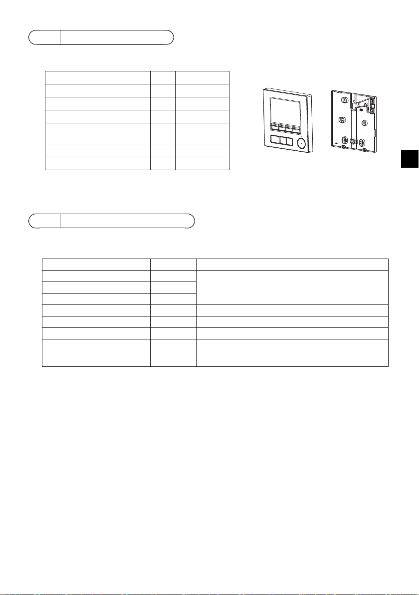
部件名称 数量 外观
遥控器 (顶壳) 1 右图*1
遥控器 (底壳) 1 右图*2
圆头十字槽螺钉M4×30 2 *3
木螺钉4.1×16
(用于直接安装在墙上)
2*3
安装手册 (本手册) 1
操作手册 1
底壳*2
顶壳*1
组件名称和供应部件
箱内包括以下部件。
*3ISO公制螺纹
*4不包括遥控器电缆。
3
现场供应部件 / 所需工具
(1) 现场供应部件
以下部件为现场供应部件。
部件名称 数量 注
双开关盒或86式开关盒 1 直接安装在墙上时不需要
薄壁金属导管 依需
防松螺母和衬套 依需
电缆盖 依需 沿墙敷设遥控器电缆时需要
油灰 适量
锚栓 依需
遥控器电缆
(使用0.3平方毫米 (AWG22)
2芯护套电缆。)
依需
SC
(2) 现场供应工具
• 平口螺丝刀 (宽度:3-5毫米 (1/8-7/32英寸))
•钳子
•杂项工具
– 5 –
Page 6
4
TB5 TB15
TB5 TB15
bb
TB5 TB15
c
TB5 TB15
b
TB5 TB15
b
TB5 TB15
b
TB5 TB15
b
TB7 TB3
TB5 TB15
TB5 TB15
TB7 TB3
(1)
(1)
(3)
(3)
(3)
(3)
(2)
(2)
(2)
(4)
(1)
(1)
a
a
dd d
d
bb
e
f
地址=51
地址=01 地址=02
地址=55
地址=08
地址=07
地址=03
地址=04 地址=09
地址=06 地址=05
组01 组02 组03
组04
ed
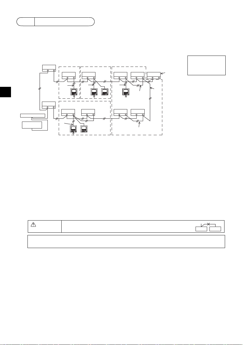
注:当联锁MA遥控器与LOSSNAY或OA处理机组时,务必设置组群中所有室内机组的地址
和LOSSNAY或OA处理机组的地址。
如何为输电线接线
将遥控器连接至CITYMULTI控制系统 (“-A” 型和之后机型)和Mr.SLIM空调 (A控制型)时,
接线不同。接线还因系统配置而异。检查使用的系统。
1. 连接至CITYMULTI控制系统
图中编号(1)至(4)对应于以下说明中的项目(1)至(4)。
连接至室内机组上
的TB15。
SC
a室外机组
b室内机组
cLOSSNAY或OA处理机组
d主遥控器
e副遥控器
f中央控制器
g输电线的电源机组
(1) 遥控器接线
• 连接至室内机组上的MA遥控器接线柱(TB15)。
• 接线柱无极性。连接至遥控器外盖底部的接线柱。
(2) 在组中运行 (以上组03和04)
• 使作为组运行的室内机组的MA遥控器接线柱(TB15)互连,并将MA遥控器连接至该点。
• 当遥控器与系统控制器配合使用时 (如上图所示),需要对系统控制器 (上图中的中央控制器)
的组进行设置。
(3) 可连接的遥控器数量
室内机组组成的每个分组可连接一个主遥控器和一个副遥控器 (总共两个)。
(4) 要联锁至LOSSNAY或OA处理机组,请使用遥控器进行下列设置。(关于联锁设置说明,请参阅
第10节“ 服务菜单 ”(5)“LOSSNAY设置 ”。)
设置LOSSNAY或OA处理机组地址和要联锁的所有室内机组的地址。
(5) 遥控器接线的总长度
• MA遥控器最远可接线至200米 (656英尺)。
注意 遥控器无法接线在一起。只能将一根电线连接至遥控器接线
柱。
– 6 –
Page 7
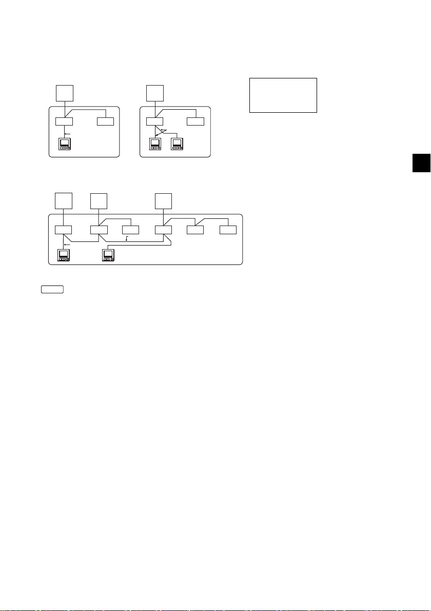
2. 连接至Mr.SLIM空调
(1)
TB5
TB4
TB1
TB4
(3)
(3)
(1)
TB4
TB4
TB5
TB1
a
bb
d
a
bb
de
(3)
冷媒地址=00 冷媒地址=00
两个同步 两个同步
TB4
TB4
TB4
TB4
TB4TB4
TB1 TB1 TB1
TB5
TB5
TB5
(2)
(1)
(3)
(2)
aa a
bbbbbb
d
标准1:1两个同步
三个同步
冷媒地址=01
(子地址)
冷媒地址
=00
(主地址)
冷媒地址=02
(子地址)
遥控器接线取决于系统配置。检查系统配置。如下例所示为遥控器接线。
图中编号(1)至(3)对应于以下说明中的项目(1)至(3)。
[1] 连接每个冷媒系统的遥控器 (标准1:1、两个同步、三个同步、四个同步)
连接至室内机组上
的TB5。
[2] 按不同的冷媒系统分组时
a室外机组
b室内机组
d主遥控器
e副遥控器
*使用室外机组dip开关设置冷媒地址。(关于更多信息,请参阅室外机组安装手册。)
* 中的所有室内机组作为一个组进行控制。
(1) 遥控器接线
• 连接至室内机组TB5 (遥控器接线柱)。(接线柱无极性。)
• 对于同步多类型,混用不同类型的室内机组时,务必将遥控器连接至具有最多功能 (风速、叶
片、百叶板等)的室内机组。
(2) 与不同的冷媒系统进行分组时
• 使用遥控器接线分组。将遥控器连接至要分组的各冷媒系统的任意室内机组。
• 同一组中混用不同类型的室内机组时,务必将室外机组与具有最多功能 (风速、叶片、百叶板
等)的室内机组相连,也就是主机组 (冷媒地址=00)。同样,当主机组为同步多类型时,务必
满足以上条件(1)。
• 作为一组,MA遥控器最多可控制16个冷媒系统。
(3) 每组最多可连接两个遥控器
• 每组仅连接一个遥控器时,应将其设置为主遥控器。每组连接两个遥控器时,应设置主遥控器及
副遥控器。(关于主 / 副设置说明,请参阅本手册初始设置章节。)
SC
– 7 –
Page 8
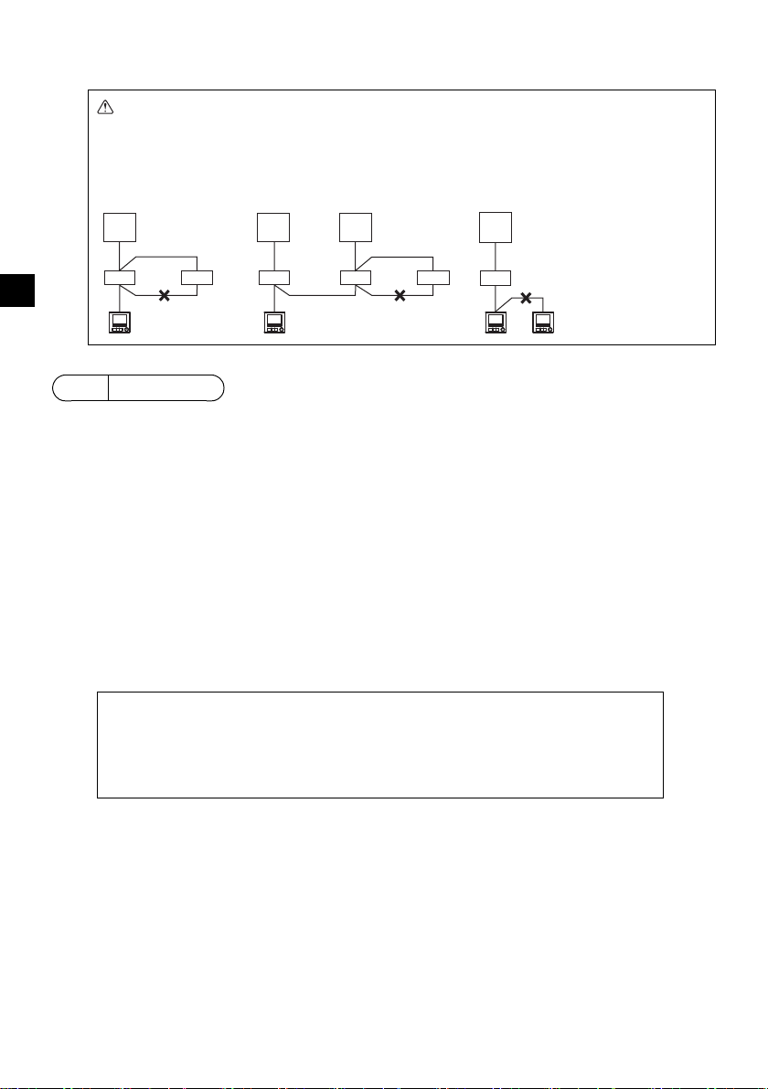
(4) 遥控器接线的总长度
冷媒地址=00 冷媒地址
=00
冷媒地址=01
冷媒地址=00
两个同步 标准1:1 两个同步 标准1:1
■ 墙上测量的室内温度与实际室内温度存在差异。
如果符合以下条件,则推荐使用室内机组上的温度传感器。
• 由于气流分布不均,供气不易到达墙上安装遥控器的位置。
• 墙的温度和实际室内温度之间差异很大。
• 墙的背面直接暴露在室外空气中。
注:温度快速变化时,可能会无法准确地测量出温度。
重要
• MA遥控器最远可接线至450米 (1476英尺)。
注意 -无法将接线连接至同一冷媒系统的室内机组TB5。如果已连接,系统将无法正
常运行。
-遥控器无法接线在一起。只能将一根电线连接至遥控器接线柱。
- 连接至TB5时,一个接线柱最多连接两根尺寸相同的电线。
SC
a
TB1
TB4
bbb bbb
TB5
dd d
5
如何安装
TB4
TB5
aa a
TB1 TB1
TB4
TB5
TB4
TB5 TB5 TB5
TB4
TB1
TB4
a室外机组
b室内机组
d主遥控器
e副遥控器
此遥控器供墙上安装使用。它即可安装在开关盒内又可直接安装在墙上。若直接安装在墙上,电线可
穿过遥控器的背面或顶部。
(1) 选择安装位置
在符合以下条件的位置安装遥控器 (开关盒)。
(a) 连接到带有自动下降面板的室内机组时,选择用户在操作遥控器时可检查室内机组自动下降面板操
作的位置 (关于如何操作自动下降面板,请参阅室内机组操作手册)。
(b)平坦表面
(c) 遥控器可准确测量室内温度的位置
监测室内温度的传感器位于室内机组和遥控器上。当用遥控器上的传感器监测室温时,遥控器内置
传感器会监测室温。使用遥控器上的传感器时,请遵守以下说明。
• 为准确监测室内温度,安装遥控器时请避免在阳光直射、热源以及空调的送风口进行安装。
• 请将遥控器安装在传感器能测量具有代表性室温的位置。
• 请将遥控器安装在遥控器上温度传感器周围无敷设电线的地方。(如果敷设了电线,传感器就不能
准确测量出室内温度。)
– 8 –
Page 9
(2) 安装空间
请勿将遥控器安装在遥控器表面温度和实际
室温相差很大的地方。
如果温差很大,将不能充分控制室温。
为了降低功能故障风险,请勿将遥控器安装
在水或油可能会接触到遥控器的位置,或冷
凝或腐蚀环境中。
为了避免变形和功能故障,请勿在阳光直射
的地方或在环境温度可能超过40°C
(104°F)或低于0°C (32°F)的地方安装
遥控器。
为降低遥控器发生故障和损坏的风险,请避
免将遥控器安装在导电表面上,例如未上漆
的金属板。
关于温度传感器的设置,请参阅以下任一手
册:CITYMULTI的室内机组安装手册; Mr.
SLIM的本手册。
30
(1-3/16)
30
(1-3/16)
30 (1-3/16)
120 (4-3/4)
温度传感器
单位:毫米 (英寸)
遥控器的外形尺寸
遥控器周围所需的最小空间
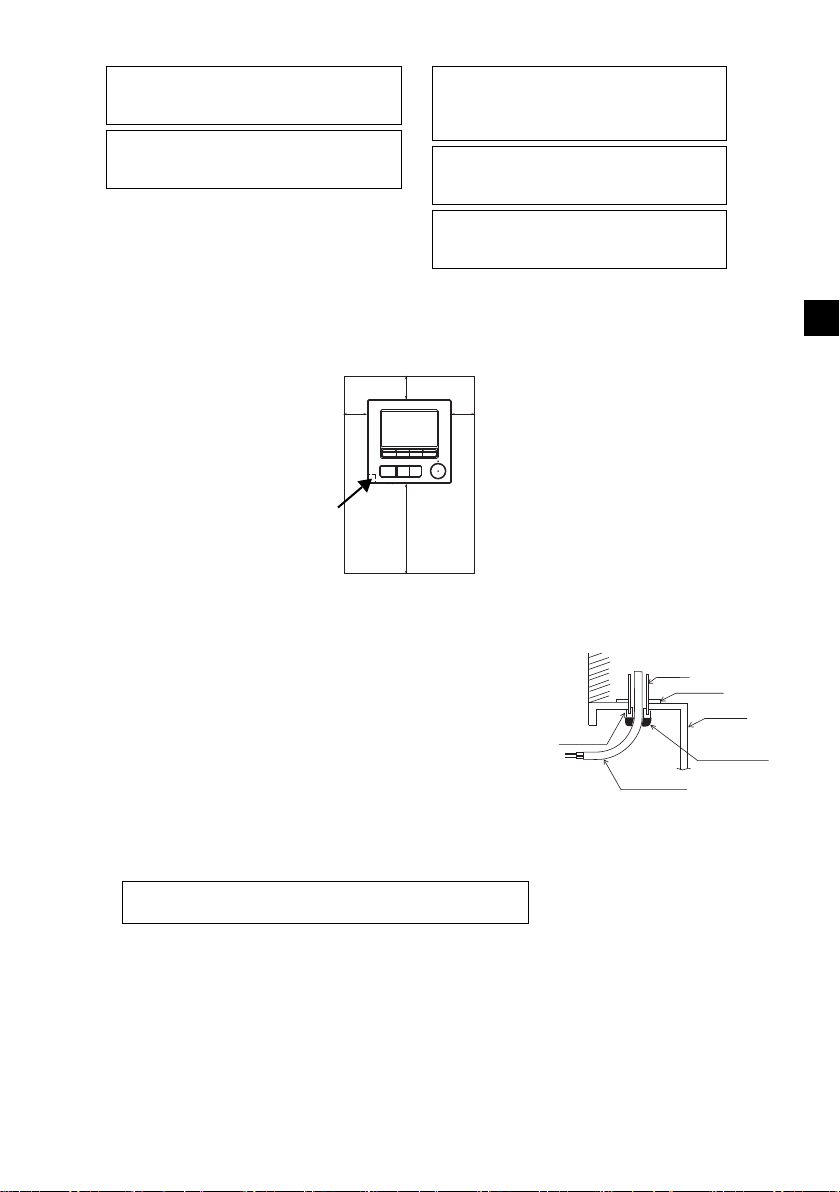
墙
导管
防松螺母
开关盒
用油灰密封
缝隙。
遥控器电缆
衬套
为了降低电击、功能故障或火灾的风险,请用油灰密封电缆与
电缆检修孔之间的缝隙。
无论遥控器是安装在开关盒内还是直接安装在墙上,请按下图所示在遥控器周围留出空间。若没有充
足的空间,将很难移动遥控器。
同样,在遥控器前面留出操作空间。
(3) 安装工作
遥控器既可安装在开关盒内又可直接安装在墙上。按照安装方法正
确地进行安装。
1 在墙上钻一个孔。
■ 使用开关盒进行安装
• 在墙上钻一个孔,在墙上安装开关盒。
• 将开关盒连接到导管。
■ 直接安装在墙上
• 在墙上钻一个孔,将电缆穿过它。
2 用油灰密封电缆检修孔。
■ 使用开关盒进行安装
• 在开关盒和导管连接处用油灰密封遥控器电缆检修孔。
SC
– 9 –
Page 10
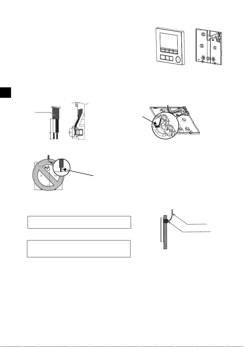
3 准备好遥控器底壳。
顶壳 底壳
护层
单位:毫米 (英寸)
连接电缆。
(无极性)
背面上不得看到2芯线。
用油灰密封缝隙。
在遥控器后面敷设电缆。
遥控器电缆
为了降低电击、短路或功能故障的风险,请勿让电线
碎片和护层刮屑进入接线柱。
请勿用免焊端子将电缆连接至接线柱。
免焊端子可能会接触到电路板并造成功能故障或遥控
器外盖受损。
重要
4 将遥控器电缆连接到底壳的接线柱上。
如下所示,将遥控器电缆护层撕下以便正确连接至接线柱。牢牢固定遥控器电缆,以便将电缆撕下的
部分装在底壳中。
SC
15 (19/32)
6 (1/4)
■ 直接安装在墙上
• 用油灰密封电缆穿过的孔。
– 10 –
Page 11
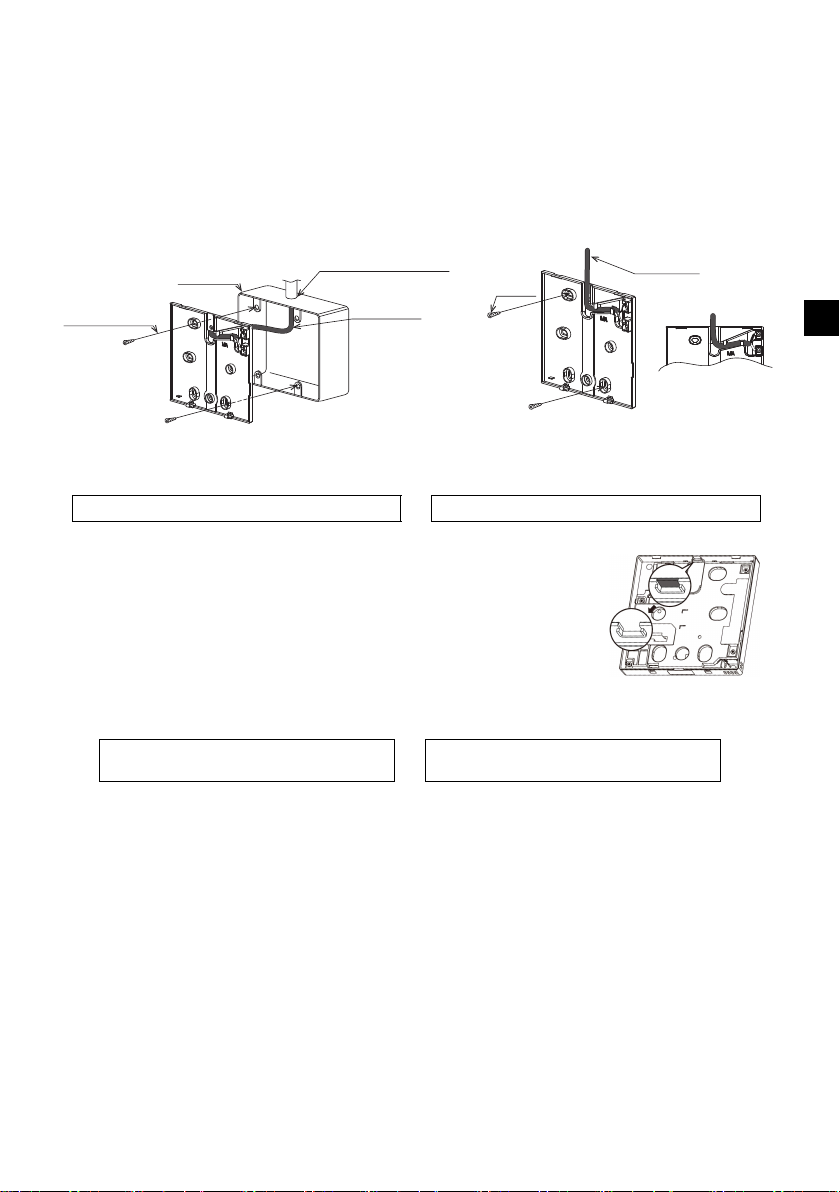
5 安装底壳。
遥控器电缆
请参阅4。
请参阅2。
双开关盒
圆头十字槽螺钉
用油灰密封电缆检修孔。
请参阅4。
木螺钉
遥控器电缆
将电缆穿过凹槽。
为了避免遥控器受损,请勿过度拧紧螺钉。 为了避免遥控器受损,请勿在遥控器外盖上钻孔。
重要
注意
为防止损坏电路板,切割电缆检修孔之前应
从顶壳上拆下前盖。
请注意,切割电缆检修孔时意外接触电路板
可能损坏电路板。
■ 使用开关盒进行安装
• 使用螺钉固定开关盒,至少固定两处盒角。
■ 直接安装在墙上
• 将电缆穿过凹槽。
• 使用螺钉固定遥控器,至少固定两角。
• 务必固定遥控器的左上方和右下方两处 (前视图角度),防止其翘起。(使用锚栓等)
■ 使用开关盒进行安装 ■ 直接安装在墙上
6 切开电缆检修孔。
■ 直接安装在墙上 (当沿墙敷设电缆时)
• 用钳子切掉外盖的薄壁部分 (右图中的阴影区域)。
• 将电缆通过该检修孔从底壳后面的凹槽穿过。
SC
– 11 –
Page 12
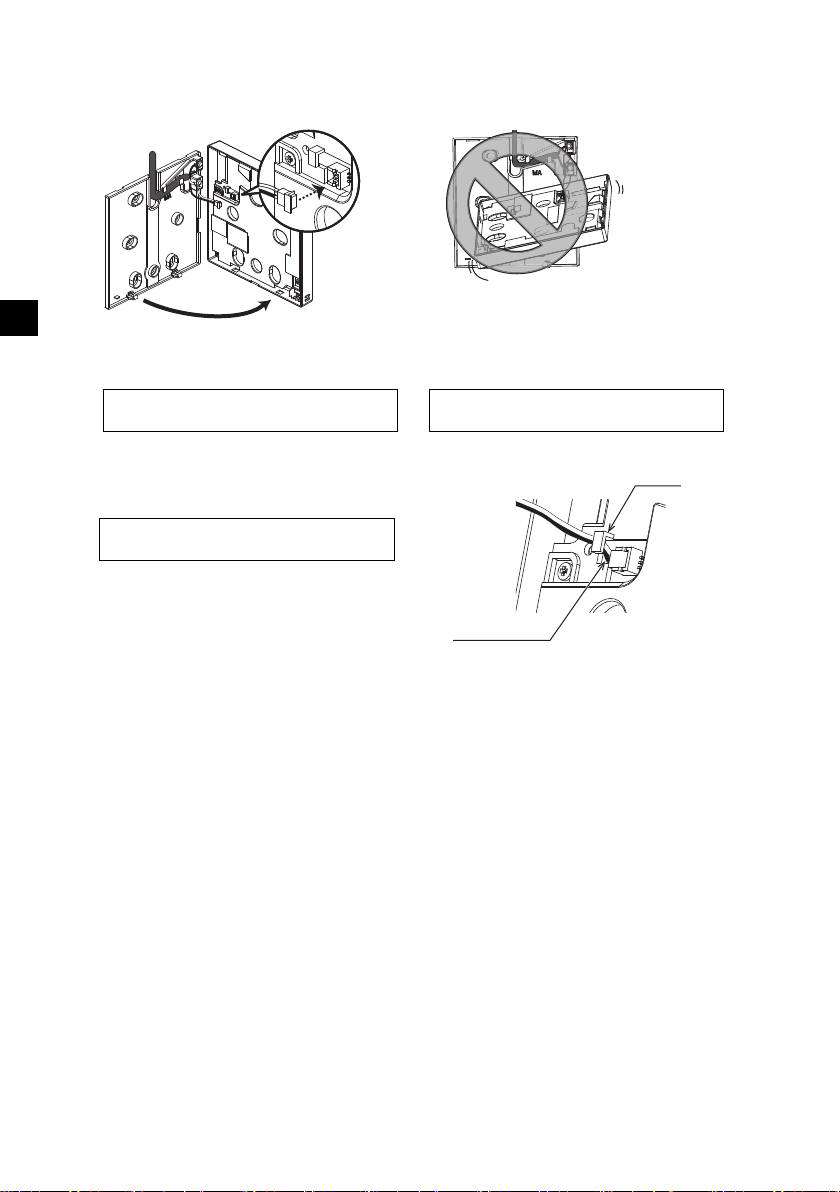
7 将连接器连接至顶壳。
连接连接器。
为了防止出现功能故障,请勿移动防护膜或
顶壳上的电路板。
为了防止电缆破损和功能故障,请勿用电缆
悬挂遥控器顶部外壳 (如上图所示)。
重要
夹子
插入电线。
用夹子固定电线,以防接线柱受力过大,引
起电缆破损。
重要
将底壳上的连接器连接至顶壳上的插座。
SC
8 将电线插入夹子中。
– 12 –
Page 13
9 将顶壳安装至底壳。
墙
不应浮起。
将顶壳连接到底壳时,请推动它直至卡入到
位。
如果没有正确锁至定位,它们将会掉落引起
人身伤害、遥控器受损或功能故障。
重要
用油灰密封缝隙。
使用电缆盖。
将电缆穿过遥控器的顶部。
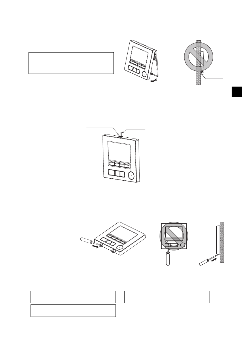
为了防止遥控器外壳受损,请勿强行将平头
螺丝刀头插入插槽转动。
请勿将平头螺丝刀插入得太深。否则会损坏
电路板。
为了防止遥控器外壳受损,请使用刀头宽度
3-5毫米 (1/8-7/32英寸)的平头螺丝刀。
重要
两个安装片位于顶壳的顶部。
将上述两个安装片钩在底壳上,并将顶壳卡入到位。检查顶壳是否牢固安装且无浮起。
■ 直接安装在墙上 (当沿墙敷设电缆时)
• 将电缆穿过遥控器顶部的检修孔。
• 用油灰密封盖上的切开部分。
• 使用电缆盖。
• 拆卸顶壳
1 拆卸顶壳
将刀头宽度为3-5毫米 (1/8-7/32英寸)的平头螺丝刀插入遥控器底部的锁闩,然后举起锁闩。然
后上拉顶壳。
SC
■ 工厂装运时,防护膜位于前盖的操作界面上。使用前,请撕下操作界面上的防护膜。
– 13 –
Page 14
SC
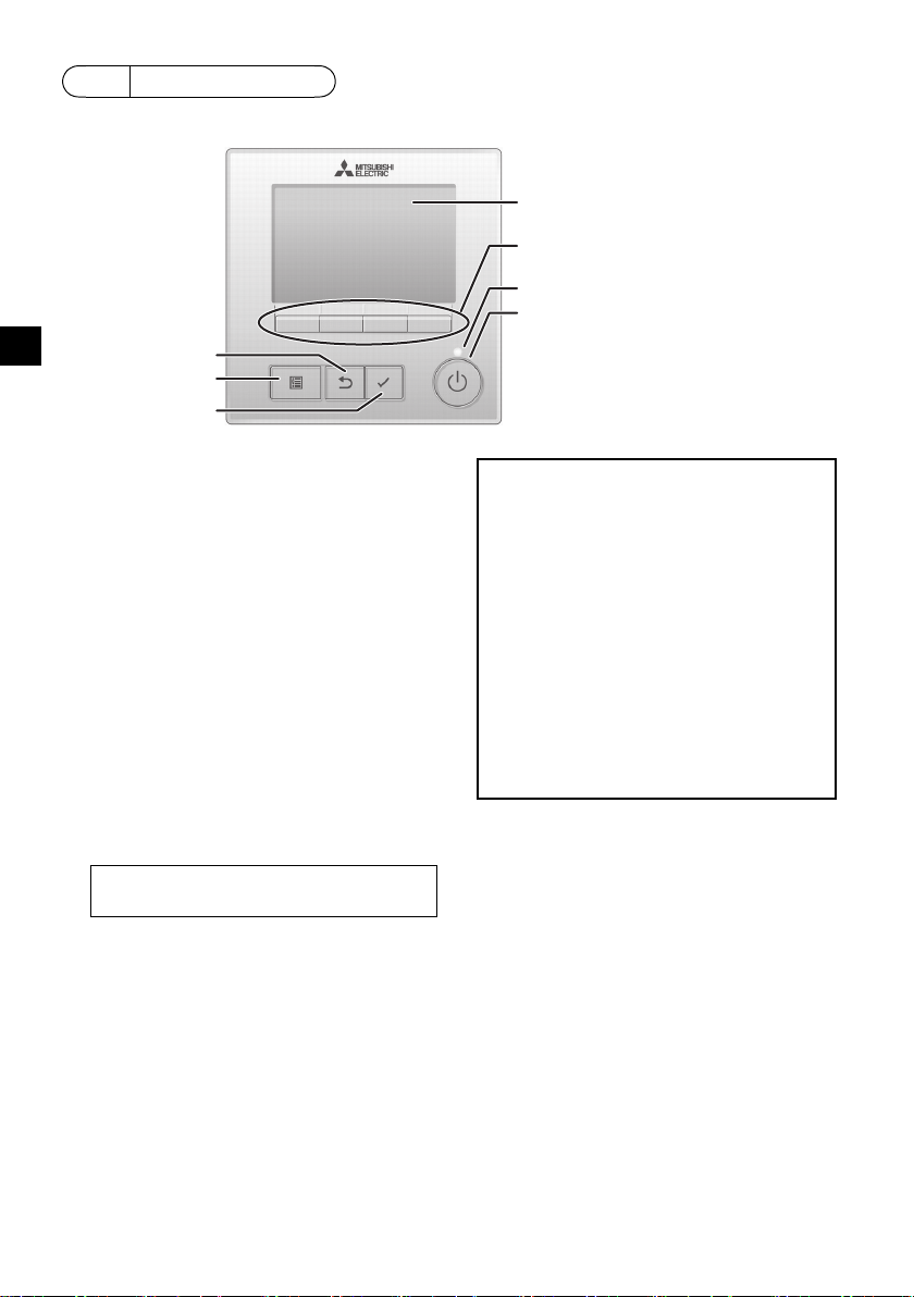
(5)“选择”按钮
(4)“返回”按钮
(3)“菜单”按钮
(7)背光LCD
(2) 功能按钮
从左开始F1、F2、F3、F4
(6)操作指示灯
(1)“ 开/关 ” 按钮
(1) “ 开/关 ” 按钮
用于开/关室内机组。
(2) 功能按钮
用于选择操作模式或在主显示上设置温度和风扇
速度。
用于选择其他画面上的项目。
(3) “菜单”按钮
用于调出主菜单。
(4) “返回”按钮
用于返回上一个画面。
(5) “选择”按钮
用于跳转至设置画面或保存设置。
(6) 操作指示灯
在正常操作状态下保持点亮。开启以及发生错误
时闪烁。
(7) 背光LCD
点显示。背光关闭时,按任意按钮可打开背光,
且其将在一定时间内保持点亮,该时间由屏幕决
定。进行任何按钮操作都将使背光保持点亮。
按设置按钮将调出如下所示的主菜单。
操作菜单*1
定时器菜单*1
节能菜单*1
初始设置菜单*2*3
维护菜单*1
服务菜单*2*3
*1 关于详细信息,请参阅光盘中的操作手册。
*2 于此手册中说明。
*3 如果在初始设置画面上10分钟不按任何按
钮,或在服务画面上2小时不按任何按钮
(在某些画面上为10分钟),画面将自动返
回至主显示。所有未保存的设置将会丢失。
菜单上的可用项目取决于连接的室内机组型号。关
于与MA触控遥控器一同封装的手册中未描述的
项目,请参阅空调机组随附的手册。
注:背光关闭时,按任意按钮可打开背光,且不
会执行按钮功能。(“ 开/关 ” 按钮除外)
6
遥控器按钮功能
– 14 –
Page 15
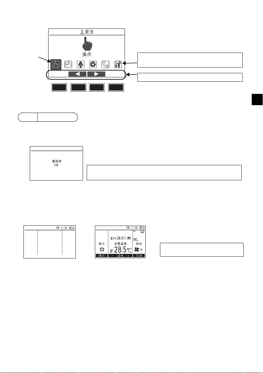
主菜单上的按钮操作
光标
使用F2和F3按钮将光标移至所需功能,然后按
“ 选择 ” 按钮进入下一页面。可能需要密码。
按钮功能向导将显示在画面底部。
F1 F2 F3 F4
注:若电源是第一次打开,将显示语言选择画面。请参阅 “ 显示设置菜单 ”
下的第9(5)节。选择所需语言。若不选择语言,系统将不会启动。
注:关于显示屏中的图标,请参阅操作手
册。
7
打开电源
打开电源前请先确保MA遥控器已按照安装手册中的指示正确安装且室内和室外机组已完成安装。
(1) 电源打开后,将显示如下画面。
正常启动
(显示处理完成的进度)
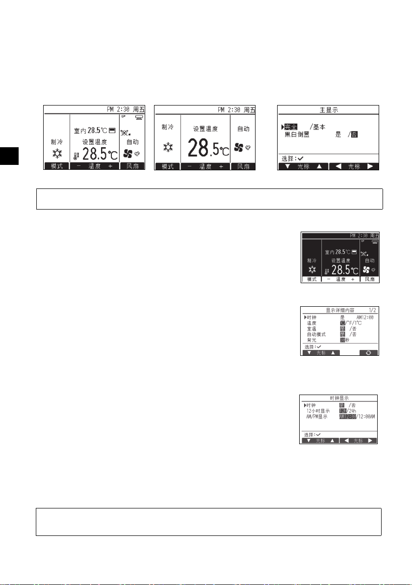
(2) 主显示
成功启动后,将显示主显示。主显示有两种不同的显示模式:“ 完全 ” 和 “ 基本 ”。如何选择显
示模式,请参阅第9节 “ 初始设置 ”。(出厂设置为 “ 完全 ” 显示模式。)
SC
完全显示模式下的主显示
(机组处于非运行状态)
完全显示模式下的主显示
(机组处于运行状态)
– 15 –
Page 16
8
注:需要维护密码。
注:关于维护密码的信息,请参阅第10节“ 服务菜单 ”。
注:需要管理员密码。
注:初始管理员密码为 “0000”。关于
密码更改方法,请参阅第(4)节 “ 管
理员密码设置 ”。
试运行
(1) 实施试运行前,请先阅读室内机组安装手册中关于试运行的章节。
(2) 在主显示画面下,按设置按钮,选择服务 > 试运行 > 试运行。
(3) 如有必要,可按 “ 开/关 ” 按钮取消试运行。
(4) 关于试运行的详细信息及如何处理试运行中出现的错误,请参阅室内机组安装手册。
SC
9
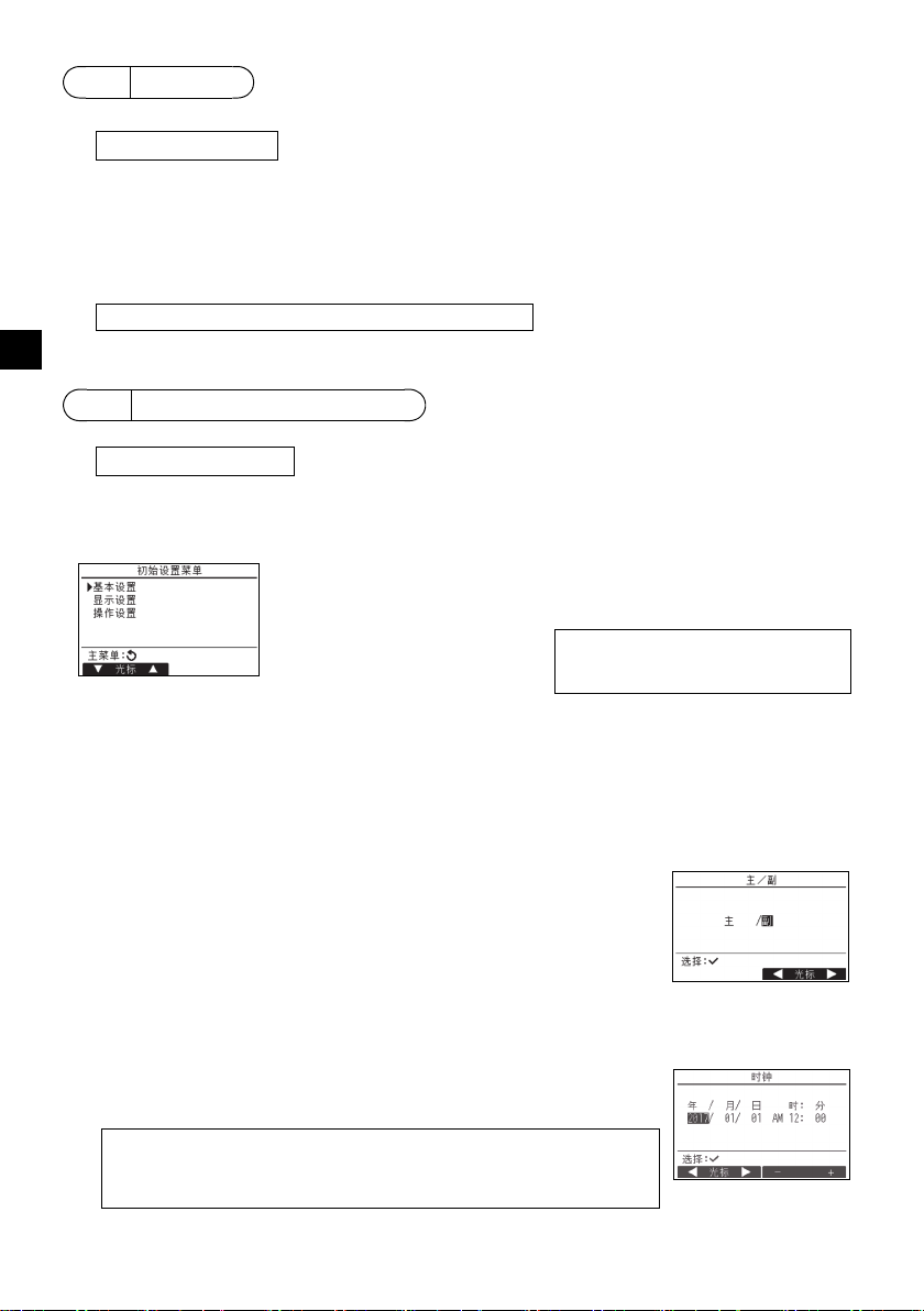
初始设置 (遥控器设置)
在主显示画面下,选择主菜单 > 初始设置,然后在显示的画面中进行遥控器设置。
基本设置菜单
•主/副
•时钟
• 夏令时
• 管理员密码
显示设置菜单
• 主显示
• 遥控器显示详细内容设置
• 对比、亮度
• 语言选择
基本设置菜单
(1) 主 / 副设置
连接两个遥控器时,其中一个需指定为副遥控器。
[ 按钮操作 ]
[1] 按F3或F4按钮,将高亮显示当前所选的设置。选择 “ 副 ” 并按
“ 选择 ” 按钮保存更改。
[2] 按 “ 菜单 ” 按钮返回至主菜单画面。(此按钮总是调出主菜单画
面。)
操作设置菜单
•自动模式
(2) 时钟设置
[ 按钮操作 ]
1 使用F1或F2按钮将光标移至所需项目。
2 使用F3或F4按钮更改日期和时间,按 “ 选择” 按钮保存更改。状态显
示和主显示的时钟显示会反映出更改。
注:时钟设置十分必要,因其会影响时间显示、周定时器、定时器设置和错误记
录。第一次使用机组或长时间未使用后请确保进行时钟设置。
注:如果给定系统未配有系统控制器,时钟时间将不会自动修正。在这种情况
下,应定期修正时钟时间。
– 16 –
Page 17
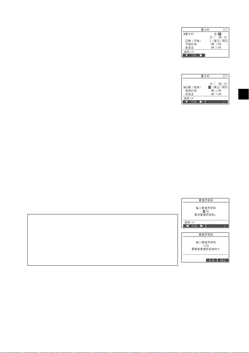
(3) 夏令时
可设置夏令时的开始 / 结束时间。夏令时功能将基于设置内容激活。
• 如果给定系统配有系统控制器,应禁用此设置以保持时间准确。
• 在夏令时开始和结束时,定时器可能会动作两次或完全不动作。
• 设置时钟后此功能方可生效。
[ 按钮操作 ]
1 使用F1至F4按钮可激活/取消激活夏令时功能或设置开始 /结束时间。
•夏令时
选择 “ 是 ” 激活夏令时,或 “ 否 ” 取消激活。
•日期(开始)
设置夏令时开始的星期、周数和月份。
•开始时间
设置夏令时的开始时间。
•前进至
设置在以上开始时间中何时让时钟前进至。
• 日期 (结束)(第二页)
设置夏令时结束的星期、周数和月份。
• 结束时间 (第二页)
设置夏令时的结束时间。
• 后退至 (第二页)
设置在以上结束时间中何时让时钟后退至。
2 按 “ 选择 ” 按钮保存设置。
*如果选择 “ 第五 ” 为周数且第五周在所选月份中不存在时,该设置
被视为 “ 第四 ”。
(4) 管理员密码设置
[ 按钮操作 ]
1 将显示输入新密码的窗口。输入新密码,然后按 “ 选择 ” 按钮。
2 在确认密码更改画面下按F4按钮 (确定)保存更改。按F3按钮 (取
消)取消更改。
SC
注:初始管理员密码为 “0000”。视需要更改默认密码,以防未授权访问。密
码仅提供给需要的人员。
注:若忘记管理员密码,可在管理员密码设置画面下,按住F1按扭10秒钟,将
密码初始化为默认密码 “0000”。
注:设置下列项目时需要输入管理员密码。
• 定时器设置• 周定时器设置• 节能设置
• 室外机组静音模式设置• 限制设置
•夜间节能设置•初始设置
关于如何设置以上项目的详细信息,请参阅遥控器随附的操作手册。
– 17 –
Page 18
显示设置菜单
(1) 主显示设置
[ 按钮操作 ]
将光标移至 “ 完全 / 基本 ”,然后使用F3或F4按钮选择 “ 完全 ” 或 “ 基本 ” 显示模式。
(出厂设置为 “ 完全 ” 显示模式。)
SC
完全显示模式 (示例) 基本模式 (示例)
注:此设置只用于主显示模式。在基本模式下,表示定时器和日程设置控制状态的图标不显示。叶片、百叶板、
通风设置或室温也不会显示。
(2) 黑白倒置设置
将光标移至 “ 黑白倒置 ”,然后使用F3或F4按钮选择显示模式
“ 是 ” 或 “ 否 ”。(出厂设置为 “ 否 ”。)
选择 “ 是 ” 将倒置显示颜色,即白色背景转换为黑色,而黑色字体转换
为白色,如右所示。
(3) 遥控器显示详细内容设置
视需要进行遥控器相关项目的设置。
按 “ 选择 ” 按钮保存更改。
[1]时钟显示
[ 按钮操作 ]
1 从显示详细内容设置画面中选择 “ 时钟 ”,然后按F4按钮 (更改)调
出时钟显示设置画面。
2 通过F1至F4按钮选择 “ 是 ”(显示)或 “ 否 ”(不显示)以及状态
显示和主显示中的时间显示格式。
3 按 “ 选择 ” 按钮保存设置。(出厂设置为 “ 是 ” (显示),格式为
“12h”。)
时钟显示:是 (状态显示和主显示上显示时间。)
显示格式:24小时制
AM/PM显示 (在显示格式为12小时制时有效):AM/PM显示在时间之前
注:时间显示的格式也会反映在定时器和日程设置显示中。时间显示如下所示。
否 (状态显示和主显示上不显示时间。)
12小时制
AM/PM显示在时间之后
12小时制:AM12:00~AM1:00~PM12:00~PM1:00~PM11:59
24小时制:0:00~1:00~12:00~13:00~23:59
– 18 –
Page 19
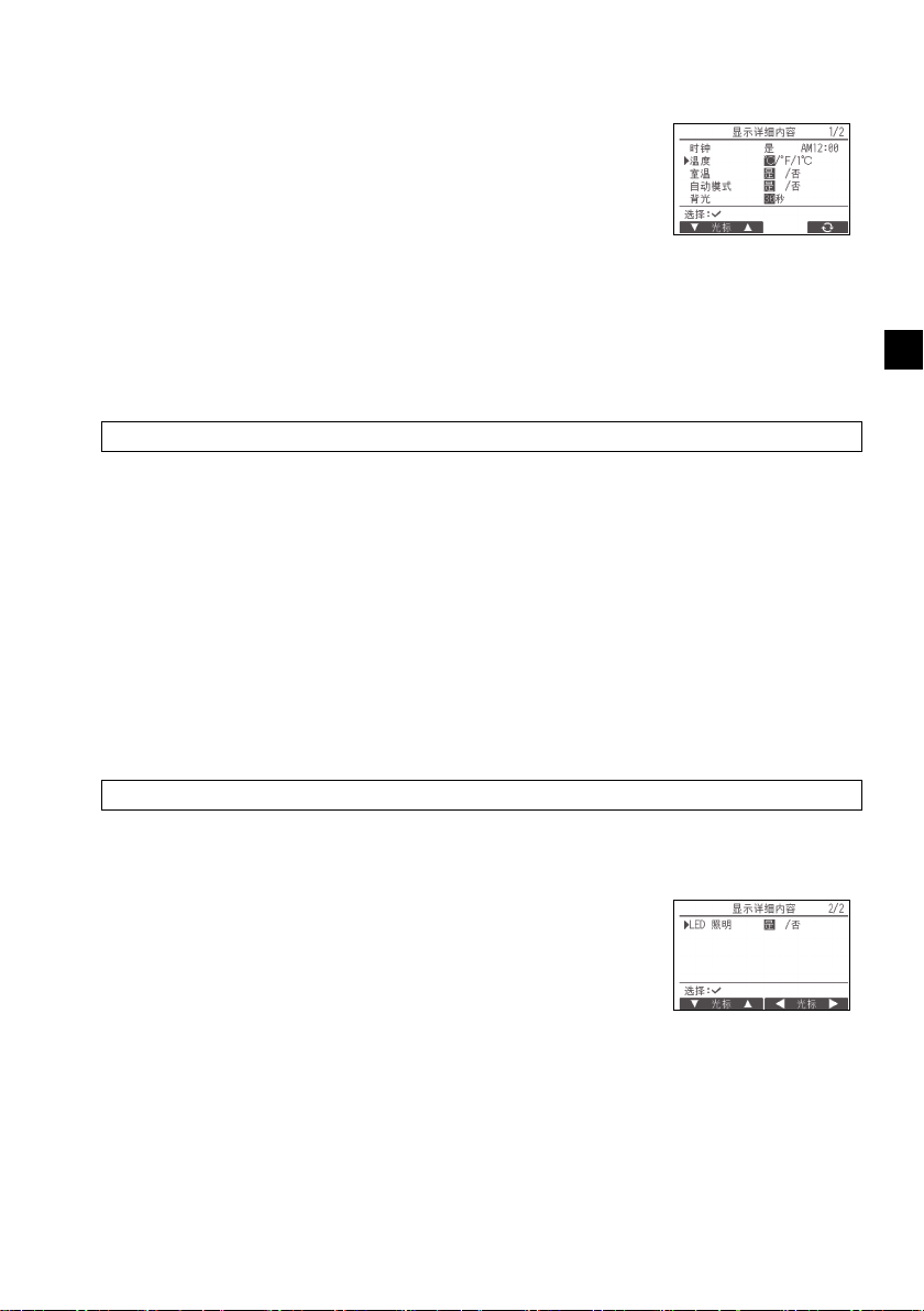
[2]温度单位设置
[ 按钮操作 ]
在显示详细内容设置画面下,将光标移至 “ 温度 ”,然后使用F3或F4
按钮选择所需的温度单位。(出厂设置为摄氏度 (°C)。)
• °C:温度以摄氏度单位显示。根据室内机组的机型,以0.5或1度的
增量显示温度。
• °F: 温度以华氏温度显示。
• 1°C:温度以摄氏度单位按1度的增量显示。
[3]室温显示
[ 按钮操作 ]
在显示详细内容设置画面下,将光标移至 “ 室温 ”,然后使用F3或F4按钮选择所需的设置。
(出厂设置为 “ 是 ”。)
• 是:在主显示上显示室温。
• 否:在主显示上不显示室温。
注:在 “ 基本 ” 模式下,即使设置为 “ 是 ”,主显示也不显示室温。
[4]自动 (单设置点)模式显示设置
[ 按钮操作 ]
在显示详细内容设置画面下,将光标移至 “ 自动模式 ”,然后使用F3或F4按钮选择所需模式。
(出厂设置为 “ 是 ”。)
• 是:在自动 (单设置点)模式下运行时显示 “ 自动制冷 ” 或 “ 自动制热 ”。
• 否:在自动 (单设置点)模式下运行时仅显示 “ 自动 ”。
[5]背光
可设置背光点亮时间。
[ 按钮操作 ]
在显示详细内容设置画面下,将光标移至 “ 背光 ”,然后使用F4按钮选择所需时间 (5/10/20/
30/60秒)。(出厂设置为 “30” 秒。)
注:此设置在状态显示和主显示上有效。
SC
[6]LED照明
LED照明可设置为 “ 是 ” (开)或 “ 否 ” (关)。(出厂设置为
“ 是 ”。)
选择 “ 否 ” 时,LED即使在正常运行期间也不会点亮。
– 19 –
Page 20
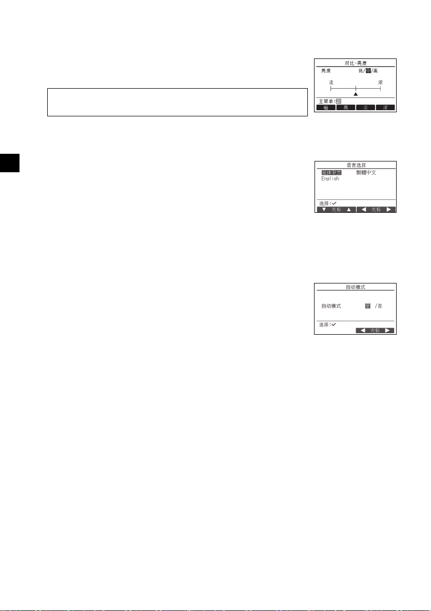
(4) 对比、亮度
[ 按钮操作 ]
使用F1和F2按钮选择遥控器LCD的所需亮度。
使用F3或F4按钮调节对比。当前级别以三角形表示。
注:调节对比和亮度可改善不同光照条件和安装地点的查看效果。此设置并不能
改善所有方向的查看效果。
(5) 语言选择
[ 按钮操作 ]
使用F1至F4按钮将光标移至所需语言。
SC
按 “ 选择 ” 按钮保存设置。
操作设置菜单
(1) 自动模式设置
[ 按钮操作 ]
可使用F3或F4按钮选择是否采用自动 (单设置点)模式或自动 (双设
置点)模式。此设置仅在连接了具有自动模式功能的室内机组时有效。
(出厂设置为 “ 是 ”。)
按 “ 选择 ” 按钮保存所做更改。
• 是:可在操作模式设置中选择自动模式。
• 否:不可在操作模式设置中选择自动模式。
– 20 –
Page 21
10
注:需要维护密码。
服务菜单
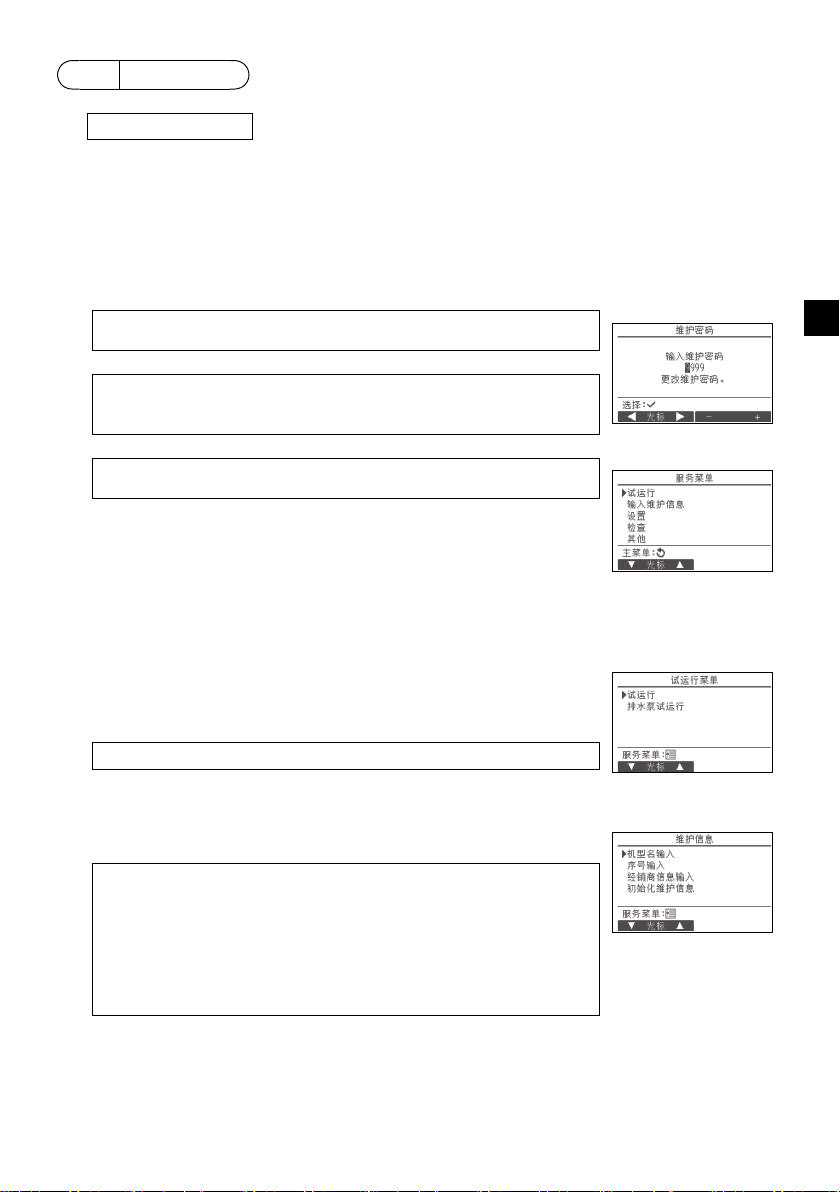
在主显示下,按设置按钮,然后选择 “ 服务 ” 进行维护设置。
选择服务菜单后会出现要求输入密码的窗口。
输入现在的维护密码 (4位数字),使用F1或F2按钮将光标移至需要更改的数字,使用F3或F4按
钮设置每个数字 (0至9)。然后按 “ 选择 ” 按钮。
注:初始维护密码为 “9999”。视需要更改默认密码,以防未授权访问。密码
仅提供给需要的人员。
注:若忘记维护密码,可在维护密码设置画面下,按住F1按扭10秒钟,将密码
初始化为默认密码 “9999”。
注:进行某些设置时可能需要停止空调机组。系统处于中央控制状态下时某些设
置可能无法进行。
(1) 试运行 (CITYMULTI和Mr.SLIM)
在服务菜单中选择 “ 试运行 ” 调出试运行菜单。
• 试运行:选择此选项执行试运行。
• 排水泵试运行:选择此选项执行室内机组排水泵试运行。
仅适用于支持试运行功能的室内机组类型。
注:关于试运行的详细信息,请参阅室内机组安装手册。
(2) 输入维护信息 (CITYMULTI和Mr.SLIM)
在服务菜单中选择 “ 输入维护信息 ” 调出维护信息画面。关于如何进行
设置的信息,请参阅室内机组安装手册。
注:以下设置可从维护信息画面中进行。
· 注册机型名和序号
输入室外和室内机组的机型名和序号。输入的信息会显示在错误信息画面
中。机型名最多可有18个字符,序号最多可有8个字符。
· 注册经销商信息
输入经销商电话号码。输入的信息会显示在错误信息画面中。电话号码最多
可有13个字符。
· 初始化维护信息
选择所需项目以初始化机型名、序号和经销商信息设置。
SC
– 21 –
Page 22
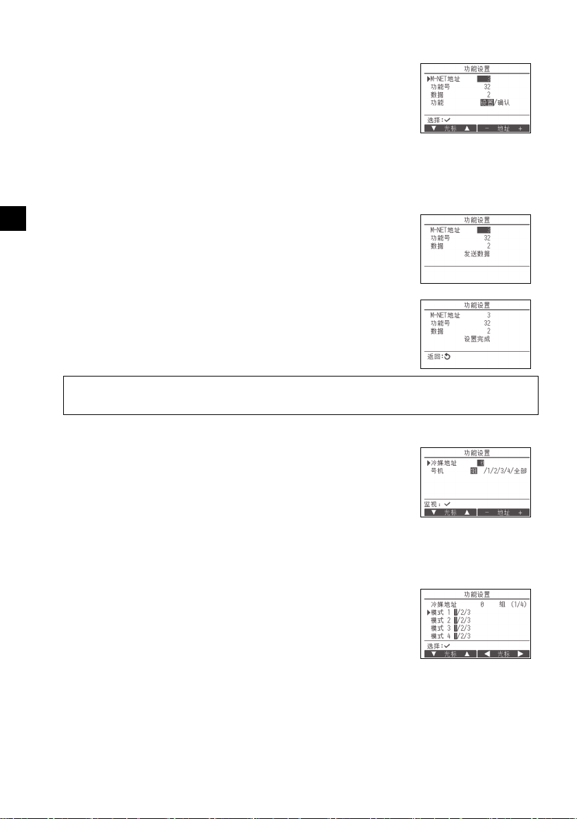
(3) 功能设置(CITYMULTI)
视需要通过遥控器设置室内机组功能。
在设置菜单中选择 “ 功能设置 ” 调出功能设置画面。
[ 按钮操作 ]
1 将显示功能设置画面。
按F1或F2按钮将光标移至以下项目之一:M-NET地址、功能设置号码或设置值。然后,按F3
或F4按钮将设置更改为所需设置。
2 设置完成后,按 “ 选择 ” 按钮。
SC
将显示表示正在发送设置信息的画面。
要检查给定机组的当前设置,请输入机组的M-NET地址设置和功能设
置号码,选择功能中的确认,然后按 “ 选择 ” 按钮。
将显示表示正在搜索设置的画面。搜索完成后,将显示当前设置。
3 当设置信息已发送时,将显示表示发送已完成的画面。
要进行其他设置,请按 “ 返回 ” 按钮返回至以上步骤2中所示的画
面。按以下步骤设置其他室内机组的功能号码。
注:
·关于室内机组出厂设置、功能设置号码和设置值的信息,请参阅室内机组安装手册。
·安装工作完成后,若有任何初始设置被更改,请确保记录下所有的功能设置。
(4) 功能设置 (Mr.SLIM)
视需要通过遥控器设置室内机组功能。
在设置菜单中选择 “ 功能设置 ” 调出功能设置画面。
[ 按钮操作 ]
1 使用F1至F4按钮设置室内机组冷媒地址和号机,然后按 “ 选择 ” 按钮确认当前设置。
2 完成从室内机组收集数据后,当前设置将高亮显示。未高亮显示的项目
表示没有进行功能设置。画面显示根据 “ 号机 ” 设置而异。
通用项目
– 22 –
Page 23
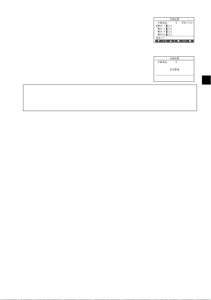
3 使用F1或F2按钮移动光标选择模式号码,使用F3或F4按钮更改设
置号码。
个别项目
(号机1到4)
4 设置完成后,按 “ 选择 ” 按钮从遥控器发送设置的数据至室内机组。
5 传送成功完成后,画面会返回至功能设置画面。
注:
·根据需要在Mr.SLIM机组上进行表1所示的功能设置。
·如需进行CITYMULTI机组的设置,请参阅操作手册。
·表1概括了每个模式号码的设置选项。关于室内机组初始设置、模式号码和设置号码的详细信息,请参阅室
内机组安装手册。
·安装工作完成后,若有任何初始设置被更改,请确保记录下所有的功能设置。
SC
– 23 –
Page 24
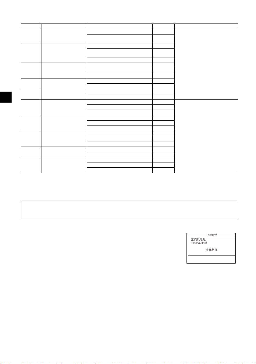
表1. 功能设置选项
模式号码 模式 设置 设置号码 号机
SC
01 电源故障后自动恢复 禁用 1 为号机设置“组”。
02 热敏电阻器选择
(检测室内温度)
03 LOSSNAY连接 未连接 1
04 电源电压 240V 1
05 自动模式 启用 (机组自动实现有效节能运行。) 1
07 过滤器信号 100小时 1 号机设置为
08 风扇速度 静音模式 (或标准) 1
09 出风口 4向 1
10 可选部件
(高效过滤器)
11 叶片 无叶片 (或叶片设置3号有效。) 1
启用 (恢复电力后需要四分钟待机时
间。)
运行中室内机组读取的平均温度 1
遥控器所连接室内机组上的热敏电阻器
(固定)
遥控器内置传感器 3
已连接 (室内机组无室外空气进气口) 2
已连接 (室内机组有室外空气进气口) 3
220V、230V 2
禁用 2
2500小时 2
未显示 3
标准 (或高天花板1) 2
高天花板 (或高天花板2) 3
3向 2
2向 3
否1
是2
有叶片 (叶片设置1号有效。) 2
有叶片 (叶片设置2号有效。) 3
这些设置将应用于所有连接的室内机
2
组。
2
“1”、“2”、“3”、“4”或 “
全部 ”。
这些设置将应用于各个室内机组。
· 若号机设置为
“1”、“2”、“3”或“4”,无
论连接的室内机组号码 (1到4机
组)是多少,此设置仅应用于特定
的室内机组。
· 若号机设置为 “ 全部 ”,无论连
接的室内机组号码 (1到4机组)
是多少,此设置应用于所有连接的
室内机组。
(5) LOSSNAY设置 (仅限CITYMULTI)
此设置仅在CITYMULTI机组操作与LOSSNAY机组联锁时需要。此设置对Mr.SLIM机组不可用。
可对连接了遥控器的室内机组进行联锁设置。(该联锁设置可被确认或删除。)
注:
·若连接了中央控制器,请使用中央控制器进行设置。
·联锁室内机组与LOSSNAY机组的操作需将该组全部室内机组和LOSSNAY机组的地址联锁。
[ 按钮操作 ]
1 在设置菜单中选择 “Lossnay” 后,遥控器将自动开始搜索当前连接的
室内机组注册的LOSSNAY地址。
– 24 –
Page 25
2 搜索完成后,将显示连接至遥控器的室内机组中最小的地址以及联锁的
LOSSNAY机组地址。若没有LOSSNAY机组与该室内机组联锁,将显
示 “--”。
若不需要进行任何设置,按 “ 返回 ” 按钮返回至设置菜单。
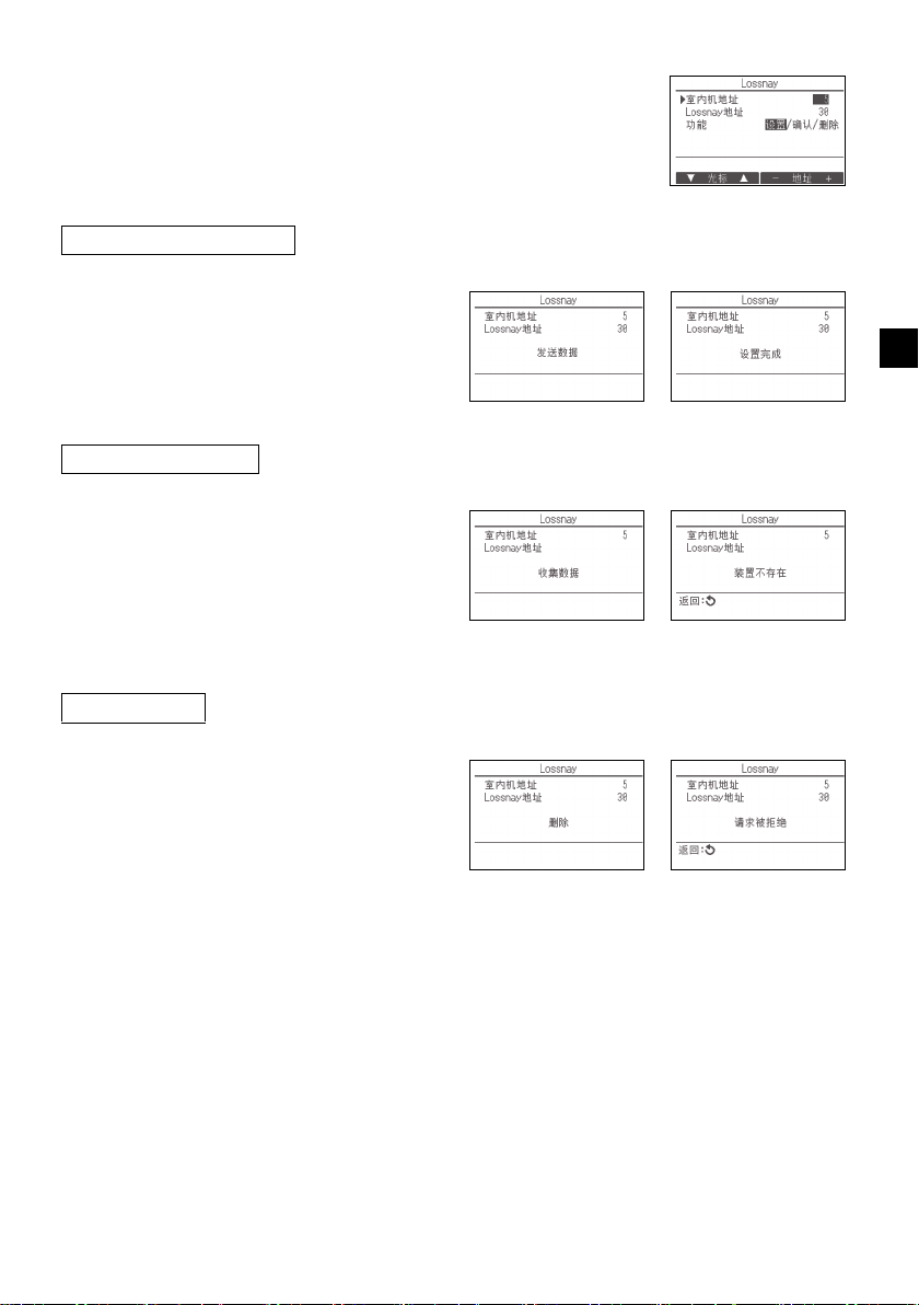
进行LOSSNAY联锁设置
3 使用F1至F4按钮输入室内机组和需联锁的
LOSSNAY机组的地址,选择 “ 功能 ” 中的
“设置”后,按“选择”按钮保存设置。
画面中将显示 “ 发送数据 ”。若设置成功完
成,将显示 “ 设置完成 ”。
搜索LOSSNAY地址
4 输入遥控器连接的室内机组地址,选择
“功能”中的“确认”,然后按
“ 选择 ” 按钮。画面中将显示
“ 收集数据 ”。若信号正确接收,将显示室
内机组和LOSSNAY地址。若未找到
LOSSNAY机组,将显示 “--”。若未找到与
输入的地址相对应的室内机组,将显示 “ 装
置不存在 ”。
删除联锁设置
SC
要删除LOSSNAY机组与连接至遥控器的室内
5
机组之间的联锁设置,使用F1至F4按钮输入
室内机组和LOSSNAY地址,选择 “ 功能 ”
中的 “ 删除 ” 后,按 “ 选择 ” 按钮。将显
示 “ 删除 ”。若删除成功,画面将返回至搜
索结果画面。若未找到与输入的地址相对应的
室内机组,将显示 “ 装置不存在 ”。若删除
失败,画面中将显示 “ 请求被拒绝 ”。
– 25 –
Page 26
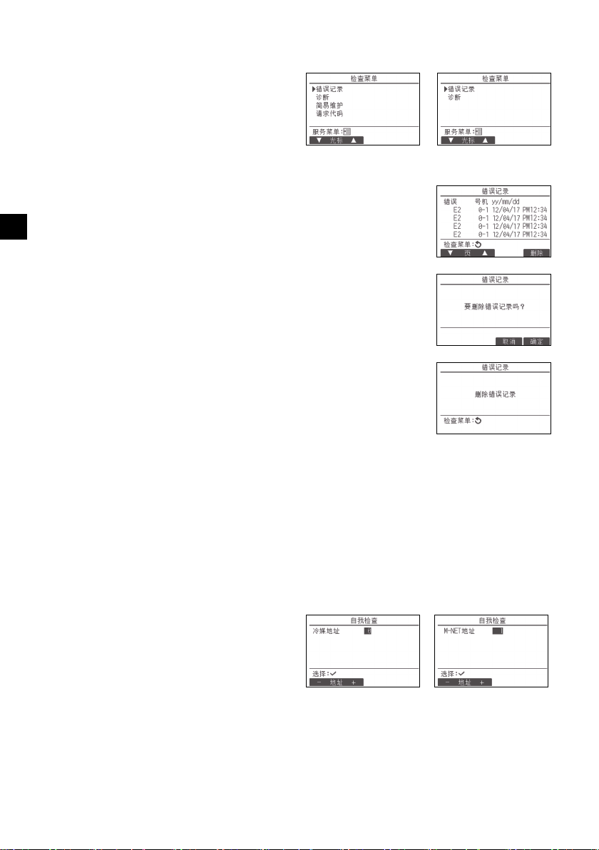
(6) 检查
在服务菜单中选择 “ 检查 ” 调出检查菜单画
面。
显示的菜单类型由连接的室内机组类型 (CITY
MULTI或Mr.SLIM)决定。
(连接CITYMULTI时,菜单中仅显示 “ 错误
记录 ”。)
[ 按钮操作 ]
1 错误记录
在检查菜单中选择 “ 错误记录 ”,然后按 “ 选择 ” 按钮可查看最多
16个错误记录。每页显示四个记录,第一页最上端的记录是最新错误记
SC
录。
[ 删除错误记录 ]
要删除错误记录,在显示错误记录的画面中按F4按钮 (删除)。将出
现确认画面询问您是否要删除错误记录。
按F4按钮 (确定)删除错误记录。
画面中将显示 “ 删除错误记录 ”。按 “ 返回 ” 按钮返回至检查菜单
画面。
2 检查菜单中的其他选项 (仅限Mr.SLIM)
在Mr.SLIM机组检查菜单中,以下选项也可用。
•简易维护
•请求代码
以上选项仅Mr.SLIM机组可用。详细信息请参阅室内机组安装手册。
<Mr.SLIM> <CITYMULTI>
(7) 诊断功能
可通过遥控器检查各机组的错误记录。
[ 按钮操作 ]
1 在诊断菜单中选择“自我检查”,然后按“选
择 ” 按钮查看自我检查画面。
2 使用F1或F2按钮输入冷媒地址 (Mr.
SLIM)或M-NET地址 (CITYMULTI),然
后按“选择”按钮。
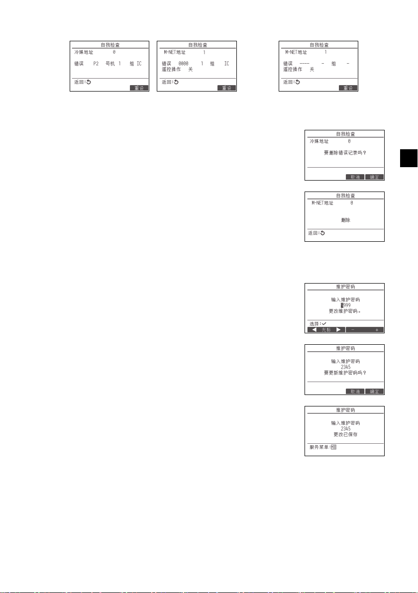
3 将显示错误代码、号机、属性和室内机组遥控
操作命令信号ON/OFF状态 (仅限CITY
MULTI)。若无可用错误记录将显示 “-”。
– 26 –
<Mr.SLIM> <CITYMULTI>
Page 27
<Mr.SLIM> <CITYMULTI>
[ 重设错误记录 ]
1 在显示错误记录的画面中按F4按钮 (重设)。将出现确认画面询问您
是否要删除错误记录。
2 按F4按钮 (确定)删除错误记录。若删除失败,将显示 “ 请求被
拒绝 ”,若未找到与输入地址相对应的室内机组,将显示 “ 装置不
存在 ”。
(8) 更改维护密码
[ 按钮操作 ]
1 在其他菜单中选择“维护密码 ”,然后按 “选择 ” 按钮调出输入新密码
的画面。
2 使用F1或F2按钮将光标移至需要更改的数字,然后使用F3或F4按
钮将每个数字设为所需数字 (0至9)。
3 按 “ 选择 ” 按钮保存新密码。
没有错误记录时
SC
4 将出现确认画面询问您是否要更改维护密码。按F4按钮 (确定)保存
更改。按F3按钮 (取消)取消更改。
5 密码更新后将出现 “ 更改已保存 ”。
6 按 “ 菜单 ” 按钮返回至服务菜单,或按 “ 返回 ” 按钮返回至 “ 维护
密码 ” 画面。
– 27 –
Page 28

(9) 遥控器信息
可检查使用中的以下遥控器信息。
•机型名
•软件版本
•序号
[ 按钮操作 ]
1 从服务菜单选择 “ 其他 ”。
2 选择 “ 遥控器信息 ”。
11
遥控器检查
SC
遥控器工作出现异常时,使用遥控器检查功能解决问题。
(1) 检查遥控器显示并查看是否有显示 (包括线路)。若未提供遥控器的正确电压 (8.5-12VDC),
遥控器将不显示任何内容。若发生此种情况,检查遥控器布线和室内机组。
[ 按钮操作 ]
1 在诊断菜单中选择“ 遥控器检查”,然后按“选择”按钮开始遥控器检查并查看检查结果。要取消
遥控器检查并退出遥控器检查菜单画面,按 “ 菜单 ” 或 “ 返回 ” 按钮。遥控器不会自行重新启
动。
选择 “ 遥控器检查 ”。 遥控器检查结果画面
OK:未发现遥控器故障。检查其他部件是否有故障。
E3,6832:输电线有噪声,或者室内机组或其他遥控器有故障。检查输电线和其他遥控器。
NG(ALL0,ALL1):发送-接收电路故障。遥控器需要更换。
ERC:数据错误数是从遥控器传输的数据位数与通过输电线实际输出的数据位数之间的差异。如果发现数据错误,
请检查输电线是否存在外部噪声干扰。
2 若显示遥控器检查结果后按 “ 选择 ” 按钮,遥控器检查将结束且遥控器会自动重新启动。
– 28 –
Page 29

所有電力作業必須由合格人員執行。
< 原文說明的譯文 >
WT08617X02
TC
CITY MULTI 控制系統
與 Mitsubishi Mr. SLIM 空調
MA 遙控器
PAR-40MAAC
安裝手冊
此安裝手冊描述如何安裝 MA 遙控器,以供三菱建築空調系統、直接膨脹式 CITY MULTI 空調室內機組
(「-A」型和之後機型)以及三菱 Mr. SLIM 箱型空調使用。
繼續安裝之前,請務必詳讀本安裝手冊。若未按照指示,則有可能導致設備損壞。
有關如何為空調機組接線並進行安裝,請參閱安裝手冊。
安裝後,請將本手冊交給使用者。
1
安全預防措施
• 安裝前請先詳閱下列安全預防措施。
• 請認真遵守下列預防措施以確保安全。
供經銷商及外包廠商使用
TC
TC
警告
注意
• 閱讀完本手冊後,請交付最終使用者保留,做為後續參考之用。
• 保留本手冊作為後續參考之用,需要時請參閱本手冊。本手冊應讓維護或搬移遙控器的人員使用。請
確定本手冊轉交給任何未來的最終使用者。
代表死亡或嚴重傷害的風險。
代表嚴重傷害或結構性損壞的風險。
– 1 –
Page 30

一般預防措施
安裝機組的場所不可有許多油污、蒸汽、有機溶劑或腐
蝕性氣體,如硫酸氣體,也不可是經常使用酸性和鹼性
溶劑或噴劑的場所。這些物質會影響機組的效能或侵蝕
某些機組零件,造成電擊、故障、煙霧或火災。
為減少短路、漏電、電擊、故障、煙霧或火災風險,請
勿用水或任何其他液體清洗遙控器。
為減少電擊、故障、煙霧或火災風險,手濕時切勿操作
開關 / 按鈕或觸碰其他電機零件。
為減少受傷或電擊,在清洗、維護或檢查遙控器之前,
請先停止操作並關閉電源供應。
為減少受傷或電擊,在遙控器周圍噴灑化學藥劑之前,
請先停止操作並蓋住遙控器。
為減少受傷風險,安裝、檢查或維護機組時,請勿讓兒
童接近。
正確安裝所有必要的面蓋,以免遙控器受到濕氣影響和
沾染灰塵。灰塵堆積和水會造成電擊、煙霧或火災。
為減少遙控器損壞風險,請勿對遙控器直接噴灑殺蟲劑
或其他易燃噴劑。
為減少受傷和電擊風險,避免接觸部分零件的尖銳邊
緣。
為減少受傷風險,操作遙控器時請穿著防護配備。
請諮詢經銷商如何正確處理遙控器。
為避免被破碎玻璃割傷,請勿在玻璃零件施加過多力
量。
為減少火災或爆炸風險,遙控器周圍請勿放置易燃物品
或噴灑易燃噴劑。
有易燃氣體洩漏風險時,請勿安裝機組。
機組周圍有易燃氣體堆積時,機組可能著火造成火災或
爆炸。
採取適當的地震安全措施,避免遙控器造成傷害。
妥善丟棄包裝材料。塑膠袋有造成兒童窒息的危險。
為避免受傷,在足以支撐遙控器重量的平滑表面安裝遙
控器。
為減少短路、漏電、電擊、故障、煙霧或火災風險,請
勿在有水的地方或冷凝的環境中安裝遙控器。
遙控器僅可由合格人員按照安裝手冊中的指示安裝。
不當安裝可能造成電擊或火災。
將頂殼安裝到底殼上,直至卡入到位。
將外蓋和頂殼連接到底殼時,請推動它直至卡入到位。
如果沒有正確鎖至定位,它們將會掉落引起人身傷害、
遙控器受損或功能故障。
警告
注意
TC
安裝時的預防措施
警告
注意
– 2 –
Page 31

接線的預防措施
為減少遙控器損壞、故障、煙霧或火災風險,請勿將電
源線連接信號端子區。
正確保護纜線,預留足夠的纜線空間以免壓迫端子。連
接不當的纜線可能斷裂、過熱並造成煙霧或火災。
為減少受傷或電擊風險,進行電力作業前請先關閉主電
源。
所有電力作業必須由合格技師按照當地法規、標準和安
裝手冊中的指示執行。
為減少電擊風險,請在電源安裝斷路器和殘餘電流斷路
器。
為減少電擊、煙霧或火災風險,各個遙控器均須安裝斷
路器。
請使用額定值正確的斷路器和保險絲 (斷路器、本地
開關 < 開關 + 保險絲 >、無保險絲斷路器)。
若斷路器的斷流容量大於指定容量,可能造成電擊、故
障、煙霧或火災。
為減少漏電、過熱、煙霧或火災風險,使用正確等級且
載流容量足夠的纜線。
必須由合格技師進行正確接地。
請勿將接地線接至瓦斯管線、水管、避雷針或電話線。
若未正確接地,可能因電噪聲干擾而造成電擊、煙霧、
火災或故障。
為減少電擊、短路或故障風險,請勿讓金屬絲和護套刮
屑進入端子區。
為減少短路、漏電、電擊或故障風險,請勿將纜線觸碰
遙控器邊緣。
用補土填補纜線穿越孔洞,以免冷凝水、水和昆蟲進入
並造成觸電、故障或火災。水滲入和機組內部形成的冷
凝水可能造成電路板損壞。
僅可由合格人員維護或搬移遙控器。
請勿拆解或更動遙控器。
不當安裝或維護可能造成受傷、電擊或火災。
為減少電擊、短路或故障風險,請勿讓金屬絲和護套刮
屑進入端子區。
警告
注意
移動或維護遙控器的預防措施
警告
TC
注意
– 3 –
Page 32

額外預防措施
為避免機組損壞,使用適當工具安裝、檢查或維護機
組。
本遙控器僅能搭配 Mitsubishi Electric (三菱電機)的
建築管理系統使用。
與其他系統共同使用,或為其他用途使用本遙控器可能
造成故障。
為避免變色,請勿使用苯、稀釋劑或化學抹布清潔遙控
器。
要清潔遙控器,將軟布浸泡在有溫和清潔劑的水中,用
軟布擦拭,再用濕布擦掉清潔劑,後以乾布擦掉水份。
為避免遙控器損壞,採取靜電保護措施。
在醫院或有無線電通訊設備的場所安裝空調時,請採取
適當措施防止電噪聲干擾。
反向換流器、高頻醫療設備或無線通訊設備和發電機可
能造成空調系統故障。空調系統也可能產生電噪聲,對
這些設備的運作造成負面影響。
為避免故障,請勿將電源線和信號線綁在一起,或放在
同一個金屬軟管裡。
請將電路板和保護膜留在機殼上。
為避免遙控器損壞,請勿將螺絲鎖太緊。
使用刀刃寬 3-5 毫米 (1/8-7/32 英寸)的平頭螺絲
刀。
請勿在平頭螺絲刀插入鎖閂時用力轉動。
為避免變形和故障,請勿在陽光直射或溫度可能超過
40℃ (104℉)或低於 0℃ (32℉)的環境安裝遙控
器。
請勿將遙控器安裝在控制面板門上。振動或衝擊遙控器
可能會損壞遙控器或導致遙控器掉落。
請用夾子固定纜線。
請勿使用無焊接端子連接纜線和端子區。
無焊接端子可能接觸到電路板,造成故障或損壞遙控器
上蓋。
連接連接器後,請正確安裝頂殼。
若電源線損壞,務必由製造商、檢修服務代理商或類似
合格人員更換,以免發生危險。
本裝置不適用於生理、感官或精神能力不足或缺乏經驗
及知識之人士 (包括兒童),除非有專人監督或指導他
們使用本裝置,同時負責保障其安全。
請確實監督兒童,避免其玩弄本裝置。
本裝置係設計供專家或經訓練之使用者在商店內、輕工
業廠房和農場中使用,或供非專業人士從事商業用途。
為避免遙控器損壞,使用適當工具安裝、檢查或維護遙
控器。
為防止功能故障,請勿從外殼上移除保護膜或電路板。
請勿將遙控器安裝在控制面板門上。振動或衝擊遙控器
可能會損壞遙控器或導致遙控器掉落。
為避免損壞遙控器,請勿在遙控器上蓋鑽孔。
用夾子固定纜線,以防端子區受力過大,引起纜線破
損。
TC
– 4 –
Page 33

2
零件名稱 數量 外觀
遙控器 (頂殼) 1 右圖 *1
遙控器 (底殼) 1 右圖 *2
圓頭十字槽螺釘 M4×30 2 *3
木螺釘 4.1×16
(用於直接安裝在牆上)
2*3
安裝手冊 (本手冊) 1
操作手冊 1
底殼 *2
頂殼 *1
部件名稱和供應零件
箱內包括以下零件。
*3 ISO 公制螺絲螺紋
*4 不包括遙控器纜線。
3
現場供應零件 / 所需工具
(1) 現場供應零件
以下零件為現場供應零件。
零件名稱 數量 說明
雙開關盒或 86 型開關盒 1 直接安裝在牆上時不需要
薄型金屬導線管 依需
上鎖螺母和套管 依需
纜線蓋 依需 沿牆敷設遙控器纜線時需要
補土 適量
錨栓 依需
遙控器纜線
(使用 0.3 平方毫米 (AWG22)
2 芯護套纜線。)
依需
(2) 現場供應工具
• 平頭螺絲刀 (寬度:3-5 毫米 (1/8-7/32 英寸))
•鉗子
•其他工具
TC
– 5 –
Page 34

4
TB5 TB15
TB5 TB15
bb
TB5 TB15
c
TB5 TB15
b
TB5 TB15
b
TB5 TB15
b
TB5 TB15
b
TB7 TB3
TB5 TB15
TB5 TB15
TB7 TB3
(1)
(1)
(3)
(3)
(3)
(3)
(2)
(2)
(2)
(4)
(1)
(1)
a
a
dd d
d
bb
e
f
地址 = 51
地址 = 01 地址 = 02
地址 = 55
地址 = 08 地址 = 07
地址 = 03
地址 = 04 地址 = 09
地址 = 06
地址 = 05
分組 01 分組 02 分組 03
分組 04
註:聯鎖 MA 遙控器與 LOSSNAY 或 OA 處理單元時,務必設定分組內所有室內機組的地址和
LOSSNAY 或 OA 處理單元的地址。
輸電線接線方式
遙控器連接至 CITY MULTI 控制系統 (「-A」型和之後機型)與連接至 Mr. SLIM 空調 (A 控制型)的
接線方式不同。接線也會因系統組態而有所不同。請檢查所使用的系統。
1. 連接 CITY MULTI 控制系統
圖中數字 (1) 至 (4) 對應至下列說明中的項目 (1) 至 (4)。
連接至室內機組的
TB15。
TC
a 室外機組
b 室內機組
c LOSSNAY 或 OA 處理單元
d 主遙控器
e 副遙控器
f 中央控制器
g 輸電線電源供應器
(1) 從遙控器接線
• 連接至室內機組的 MA 遙控器端子區 (TB15)。
• 端子區不分極性。連接至遙控器外殼底部的端子區。
(2) 分組操作 (分組 03 和 04 以上)
• 將想要分組操作之室內機組的 MA 遙控器端子區 (TB15)互連,然後將 MA 遙控器連接至該互連
點。
• 如上圖所示將遙控器結合系統控制器使用時,需要在系統控制器 (上圖中的中央控制器)上進行
分組設定。
(3) 可連接的遙控器數量
室內機組組成的每個分組可連接一部主遙控器和一部副遙控器 (總共兩部)。
(4) 若要聯鎖 LOSSNAY 或 OA 處理單元,請使用遙控器進行下列設定。(如需聯鎖設定的說明,請參
閱第 10 節 「服務選單」 (5) 「LOSSNAY 設定」。)
設定 LOSSNAY 或 OA 處理單元的地址及想要聯鎖的所有室內機組的地址。
(5) 遙控器接線總長度
• MA 遙控器的電線長度最長可達 200 公尺 (656 英尺)。
注意 遙控器不得接線在一起。只能連接一條線到遙控器端子區。
– 6 –
ed
Page 35

2. 連接 Mr. SLIM 空調
(1)
TB5
TB4
TB1
TB4
(3)
(3)
(1)
TB4
TB4
TB5
TB1
a
bb
d
a
bb
de
(3)
冷媒 地址 = 00 冷媒 地址 = 00
雙機同步 雙機同步
標準一對一雙機同步
三機同步
冷媒地址 = 01
(次要)
冷媒地址
= 00
(主要)
冷媒地址 = 02
(次要)
遙控器的接線因系統組態而有所不同。請檢查系統組態。請依照以下範例中所示為遙控器接線。
圖中數字 (1) 至 (3) 對應至下列說明中的項目 (1) 至 (3)。
[1] 連接各冷媒系統的遙控器 (標準一對一、雙機同步、三機同步、四機同步)
連接至室內機組的
TB5。
[2] 依不同的冷媒系統分組時
aa a
TB1 TB1 TB1
TB4
bbbbbb
TB5
(2)
TB5
(1)
(3)
d
TB4TB4
TB4
(2)
TB5
TB4
TB4
a 室外機組
b 室內機組
d 主遙控器
e 副遙控器
* 請用室外機組上的指撥開關設定冷媒地址。(有關詳細資訊,請參閱室外機組安裝手冊。)
* 以 括住的所有室內機組作為同一個分組控制。
(1) 從遙控器接線
• 連接至室內機組 TB5 (遙控器端子區)。(端子區不分極性。)
• 多機同步類型在混合不同類型的室內機組時,務必將遙控器連接至擁有最多功能的室內機組 (風
速、葉片和百葉板等)。
(2) 將不同的冷媒系統分組時
• 使用遙控器接線分組。將遙控器連接至想要分組的各冷媒系統的任一室內機組。
• 在同一分組內混合不同類型的室內機組時,務必將室外機組連接至擁有最多功能的室內機組 (風
速、葉片和百葉板等),也就是主機組 (冷媒地址 = 00)。此外,主機組為多機同步類型時,務
必滿足上述 (1) 的條件。
• MA 遙控器可控制一個分組中最多 16 部冷媒系統。
(3) 一個分組最多可連接兩個遙控器
• 只有一個遙控器連接至一個分組時,請設定為主遙控器。兩個遙控器連接至一個分組時,請設定
主遙控器與副遙控器。(如需主 / 副設定的說明,請參閱本手冊內初始設定章節。)
TC
– 7 –
Page 36

(4) 遙控器接線總長度
dd d
TB4
TB4
TB4
TB4
TB4
TB4
TB1
TB1 TB1
TB1
TB5
TB5
TB5
TB5 TB5 TB5
a
bbb bbb
aa a
冷媒地址 = 00 冷媒地址
= 00
冷媒地址 = 01
冷媒地址 = 00
雙機同步 標準一對一 雙機同步 標準一對一
■ 牆上測量的室溫與實際室溫存在差異。
如果符合以下條件,則推薦使用室內機組上的溫度感測器。
• 由於氣流分佈不均,供氣不易到達牆上安裝遙控器的位置。
• 牆的溫度和實際室溫之間差異很大。
• 牆的背面直接暴露在室外空氣中。
註:溫度快速變化時,可能無法準確地測量出溫度。
重要
• MA 遙控器的電線長度最長可達 450 公尺 (1476 英尺)。
注意 - 電線不得連接至同一冷媒系統之室內機組的 TB5。如此連接,系統無法正常運
作。
- 遙控器不得接線在一起。只能連接一條線到遙控器端子區。
- 連接至 TB5 時,一個端子區最多連接兩條尺寸相同的線。
a 室外機組
b 室內機組
d 主遙控器
e 副遙控器
TC
5
安裝方式
此遙控器供牆上安裝使用。它既可安裝在開關盒內亦可直接安裝在牆上。直接安裝在牆上時,電線可
穿過遙控器的背面或頂部。
(1) 選擇安裝位置
在符合以下條件的位置安裝遙控器 (開關盒)。
(a) 用於連接到帶有自降面板的室內機組,需為使用者在操作遙控器時可在此檢查室內機組的自降面板
操作的位置 (有關如何操作自降面板,請參閱室內機組操作手冊。)
(b) 平滑平面
(c) 遙控器可準確測量室內溫度的位置
監測室內溫度的感測器位於室內機組和遙控器上。當用遙控器上的感測器監測室溫時,遙控器內建
的感測器會監測室溫。使用遙控器上的感測器時,請遵守以下指示。
• 為準確監測室內溫度,安裝遙控器時請避免在陽光直射、熱源以及空調的送風口進行安裝。
• 請將遙控器安裝在感測器能測量具有代表性室溫的位置。
• 請將遙控器安裝在遙控器上的溫度感測器周圍無敷設電線的地方。(如果敷設了電線,感測器無法
準確測量出室溫。)
– 8 –
Page 37

(2) 安裝空間
請勿將遙控器安裝在遙控器表面溫度和實際
室溫相差很大的地方。
如果溫差很大,將無法充分控制室溫。
為減少故障風險,請勿在有水、油汙會接觸
到遙控器、有冷凝或腐蝕性的環境安裝遙控
器。
為避免變形和故障,請勿在陽光直射或溫度
可能超過 40℃ (104℉)或低於 0℃
(32℉)的環境安裝遙控器。
為降低故障風險及對遙控器的損壞,請勿在
導電性的表面安裝遙控器,例如無塗裝的金
屬板。
有關溫度感測器的設定,請參閱以下任一手
冊:CITY MULTI 的室內機組安裝手冊;本
Mr. SLIM 安裝手冊。
30
(1-3/16)
30
(1-3/16)
30 (1-3/16)
120 (4-3/4)
溫度感測器
單位:毫米 (英寸)
遙控器的外形尺寸
遙控器周圍最小保留空間
牆壁
導線管
上鎖螺母
開關盒
用補土填補
空隙。
遙控器纜線
套管
為減少電擊、故障或火災風險,用補土填補纜線和纜線穿越孔
洞中間的空隙。
無論遙控器是安裝在開關盒內還是直接安裝在牆上,請如下圖所示在遙控器周圍留出空間。若沒有充
足的空間,將很難移動遙控器。
同樣,在遙控器前面留出操作空間。
(3) 安裝工作
遙控器既可安裝在開關盒內亦可直接安裝在牆上。按照安裝方法正
確地進行安裝。
1 在牆上鑽一個孔。
■ 使用開關盒進行安裝
• 在牆上鑽一個孔,並在牆上安裝開關盒。
• 將開關盒連接到導線管。
■ 直接安裝在牆上
• 在牆上鑽一個孔,並將纜線穿過它。
2 用補土填補纜線穿越孔洞。
■ 使用開關盒進行安裝
• 在開關盒和導線管連接處用補土填補遙控器纜線穿越孔洞。
TC
– 9 –
Page 38

3 準備好遙控器底殼。
頂殼 底殼
15 (19/32)
6 (1/4)
護層
單位:毫米 (英寸)
連接纜線。
(無極性)
2 芯線不得露出於背面。
用補土填補空隙。
在遙控器後面敷設纜線。
遙控器纜線
為減少電擊、短路或故障風險,請勿讓金屬絲和護套
刮屑進入端子區。
請勿使用無焊接端子連接纜線和端子區。
無焊接端子可能接觸到電路板,造成故障或損壞遙控
器上蓋。
重要
4 將遙控器纜線連接到底殼上的端子區。
如下所示撕下遙控器纜線護層,以正確地連接至端子區。固定遙控器纜線,讓纜線撕下的部分剛好裝
入底殼內。
TC
■ 直接安裝在牆上
• 用補土填補纜線穿過的孔。
– 10 –
Page 39

5 安裝底殼。
遙控器纜線
請參閱 4。
請參閱 2。
雙開關盒
圓頭十字槽螺釘
用補土填補纜線穿越
孔洞。
請參閱 4。
木螺釘
遙控器纜線
將纜線穿過凹槽。
為避免遙控器損壞,請勿將螺絲鎖太緊。 為避免損壞遙控器,請勿在遙控器上蓋鑽孔。
重要
請注意
為防止損壞電路板,請在切出纜線穿越孔洞
之前,先將前蓋從頂殼取下。
請注意,裁切纜線穿越孔洞時若意外碰觸到
電路板,可能使電路板損壞。
■ 使用開關盒進行安裝
• 使用螺絲固定開關盒的至少兩個角落。
■ 直接安裝在牆上
• 將纜線穿過凹槽。
• 使用螺絲固定遙控器的至少兩個角落。
• 確實固定遙控器的左上角與右下角 (由正面視之)避免翹起。(使用錨栓等)
■ 使用開關盒進行安裝 ■ 直接安裝在牆上
6 切開纜線穿越孔洞。
■ 直接安裝在牆上 (當沿牆敷設纜線時)
• 以鉗子從上蓋上薄壁處剪開 (右圖中的陰影部分)。
• 將纜線從底殼背面的凹槽穿過穿越孔洞。
TC
– 11 –
Page 40

7 將連接器連接到頂殼。
接上連接器。
為防止功能故障,請勿從頂殼上移除保護膜
或電路板。
為防止纜線破損和功能故障,請勿如上圖所
示使用纜線懸掛遙控器頂部外殼。
重要
夾子
插入電線。
用夾子固定電線,以防端子區受力過大,引
起纜線破損。
重要
將底殼上的連接器連接至頂殼上的插槽。
TC
8 將電線插入夾子。
– 12 –
Page 41

9 將頂殼安裝到底殼上。
牆壁
不應浮起。
將頂殼連接到底殼時,請推動它直至卡入到
位。
如果沒有正確鎖至定位,它們將會掉落引起
人身傷害、遙控器受損或功能故障。
重要
用補土填補空隙。
使用纜線蓋。
將纜線穿過遙控器的頂部。
為防止遙控器外殼受損,請勿強制將平頭螺
絲刀尖端插入插槽。
不要將平頭螺絲刀插得太深。否則會使電路
板損壞。
為防止遙控器外殼受損,請使用刀刃寬 3-5
毫米 (1/8-7/32 英寸)的平頭螺絲刀。
重要
兩個安裝片位於頂殼的頂部。
將上述兩個安裝片鉤在底殼上,並將頂殼卡入到位。檢查頂殼是否牢固安裝且無浮起。
■ 直接安裝在牆上 (當沿牆敷設纜線時)
• 將纜線穿過遙控器頂部的穿越孔洞。
• 用補土填補蓋上的切開部分。
• 使用纜線蓋。
TC
• 拆卸頂殼
1 拆卸頂殼
將刀刃寬 3-5 毫米 (1/8-7/32 英寸)的平頭螺絲刀插入遙控器底部的鎖閂,並抬起鎖閂。然後,將
頂殼拉起。
■ 工廠裝運時,保護膜位於前蓋的操作介面上。使用前,請撕下操作介面上的保護膜。
– 13 –
Page 42

TC
(5) [ 選擇 ] 按鈕
(4) [ 返回 ] 按鈕
(3) [ 選單 ] 按鈕
(7) 背光 LCD
(2) 功能按鈕
從左邊開始 F1、F2、F3、F4
(6) 操作指示燈
(1) [ 開/關 ] 按鈕
(1) [ 開/關 ] 按鈕
用於開/關室內機組。
(2) 功能按鈕
用於選擇操作模式或設定主顯示上的溫度和風扇
速度。
用於選擇其他畫面上的項目。
(3) [ 選單 ] 按鈕
用於調出主選單。
(4) [ 返回 ] 按鈕
用於返回上一個畫面。
(5) [ 選擇 ] 按鈕
用於跳轉至設定畫面或保存設定。
(6) 操作指示燈
在正常操作狀態下保持點亮。開啟以及發生錯誤
時閃爍。
(7) 背光 LCD
點顯示。背光關閉時,按任意按鈕可打開背光,
且其將在一定時間內保持點亮,該時間由螢幕決
定。進行任何按鈕操作都將使背光保持點亮。
按設定按鈕將調出如下所示的主選單。
操作選單 *1
定時器選單 *1
節能選單 *1
初始設定選單 *2*3
維護選單 *1
服務選單 *2*3
*1 詳細資訊請參閱光碟中的操作手冊。
*2 於此手冊中說明。
*3 如果在初始設定畫面上 10 分鐘不按任何按鈕,
或在服務畫面上 2 小時不按任何按鈕 (在某些
畫面上為 10 分鐘),畫面將自動返回至主顯
示。所有未保存的設定將會丟失。
選單上的可用項目取決於連接的室內機組型號。有
關與 MA 觸控遙控器一同封裝的手冊中未描述的項
目,請參閱空調機組隨附的手冊。
註:背光關閉時,按任意按鈕可打開背光,且不
會執行按鈕功能。([ 開/關 ] 按鈕除外)
6
遙控器按鈕功能
– 14 –
Page 43

主選單上的按鈕操作
游標
使用 F2 和 F3 按鈕將游標移至所需功能,然後按
[ 選擇 ] 按鈕進入下一頁面。可能需要密碼。
按鈕功能嚮導將顯示在畫面底部。
F1 F2 F3 F4
註:若是第一次打開電源,將顯示語言選擇畫面。請參閱 「顯示設定選單」的
第 9 節 (5)。選擇所需語言。若不選擇語言,系統將不會啟動。
註:有關顯示幕中的圖示資訊,請參閱操
作手冊。
7
打開電源
打開電源前,請確保 MA 遙控器已按照安裝手冊中的指示正確安裝,且室內和室外機組均已完成安
裝。
(1) 電源打開後,將顯示如下畫面。
正常啟動
(顯示處理完成的進度)
TC
(2) 主顯示
成功啟動後,將顯示主顯示。主顯示有兩種不同顯示模式:「完全」和 「基本」。如何選擇顯示模
式,請參閱第 9 節 「初始設定」。(出廠設定為 「完全」顯示模式。)
主顯示的完全顯示模式
(機組處於非運行狀態)
主顯示的完全顯示模式
(機組處於運行狀態)
– 15 –
Page 44

8
註:需要維護密碼。
註:有關維護密碼的資訊,請參閱第 10 節 「服務選單」 。
註:需要管理員密碼。
註:初始管理員密碼為 「0000」。欲知如
何更改密碼,請參閱第 (4) 節 「管理
員密碼設定」。
試運行
(1) 實施試運行前請先閱讀室內機組安裝手冊中有關試運行的章節。
(2) 在主顯示下,按設定按鈕,然後選擇服務 > 試運行 > 試運行。
(3) 如有必要,可按 [ 開/關 ] 按鈕取消試運行。
(4) 有關試運行的詳細資訊及如何處理試運行中出現的錯誤,請參閱室內機組安裝手冊。
TC
9
初始設定 (遙控器設定)
從主顯示選擇主選單 > 初始設定,然後在顯示的畫面中進行遙控器設定。
基本設定選單
•主/副
•時鐘
• 日光節約時間
• 管理員密碼
顯示設定選單
• 主顯示
• 遙控器顯示詳細內容設定
• 對比、亮度
• 語言選擇
基本設定選單
(1) 主 / 副設定
連接兩個遙控器時,其中一個需要指定為副遙控器。
[ 按鈕操作 ]
[1] 按下 F3 或 F4 按鈕時,當前選取的設定將加亮顯示。選擇 「副」,並
按下 [ 選擇 ] 按鈕保存更改。
[2] 按 [ 選單 ] 按鈕返回至主選單畫面。(此按鈕總是調出主選單畫面。)
操作設定選單
•自動模式
(2) 時鐘設定
[按鈕操作]
1 使用 F1 或 F2 按鈕將游標移至所需項目。
2 使用 F3 或 F4 按鈕更改日期和時間,按 [ 選擇 ] 按鈕保存更改。更改會反
映在狀態顯示和主顯示的時鐘顯示中。
註:時鐘設定十分必要,因其會影響時間顯示、週定時器、定時器設定和錯誤記
錄。第一次使用機組或長時間未使用後,請確保進行時鐘設定。
註:如果某一系統沒有系統控制器,時鐘時間將不會自動修正。在此種情況下,
應定期修正時鐘時間。
– 16 –
Page 45

(3) 日光節約時間
可設定日光節約時間的開始/結束時間。日光節約時間功能會依設定內容
啟動。
• 如果某一系統有系統控制器,請停用此設定以保持正確時間。
• 日光節約時間開始或結束時,定時器可能會作用兩次或不作用。
• 此功能需等設定時鐘後方可運作。
[按鈕操作]
1 使用 F1 至 F4 按鈕可啟動/停用日光節約時間功能或設定開始/結束時
間。
• 日光節約時間
選擇 「是」啟動日光節約時間,選擇 「否」則停用日光節約時間。
•日期(開始)
設定日光節約時間開始的星期、週數和月份。
•開始時間
設定日光節約時間的開始時間。
•前進至
設定在上述的開始時間中何時讓時鐘前進至。
• 日期 (結束)(第二頁)
設定日光節約時間結束的星期、週數和月份。
• 結束時間 (第二頁)
設定日光節約時間的結束時間。
• 後退至 (第二頁)
設定在上述的結束時間中何時讓時鐘後退至。
2 按 [ 選擇 ] 按鈕保存設定。
* 如果週數選擇 「第五」,而所選的該年該月沒有第五週,設定將視為
「第四」。
(4) 管理員密碼設定
[按鈕操作]
1 將顯示輸入新密碼的視窗。輸入新密碼,然後按 [ 選擇 ] 按鈕。
2 在確認密碼更改畫面下按 F4 按鈕 (確定)保存更改。按 F3 按鈕 (取
消)取消更改。
TC
註:初始管理員密碼為 「0000」。必要時更改預設密碼,避免未經授權的存取。
密碼僅提供給需要的人員。
註:若忘記管理員密碼,可在管理員密碼設定畫面下,按住 F1 按鈕 10 秒鐘將密
碼初始化為預設密碼 「0000」。
註:設定下列項目時需要輸入管理員密碼。
• 定時器設定 • 週定時器設定 • 節能設定
• 室外機組靜音模式設定 • 限制設定
• 夜間節能設定 • 初始設定
有關如何設定以上項目的詳細資訊,請參閱遙控器隨附的操作手冊。
– 17 –
Page 46

顯示設定選單
(1) 主顯示設定
[按鈕操作]
將游標移至 「完全/基本」,使用 F3 或 F4 按鈕選擇 「完全」或 「基本」顯示模式。(出廠設定為
「完全」顯示模式。)
TC
完全顯示模式 (範例) 基本模式 (範例)
註:此設定僅用於主顯示。在基本模式下,表示定時器和日程設定控制狀態的圖示不顯示。葉片、百葉板和通風
設定或室溫都不會顯示。
(2) 黑白反轉設定
將游標移至 「黑白反轉」,使用 F3 或 F4 按鈕選擇顯示模式 「是」或
「否」。(出廠設定為 「否」。)
選擇 「是」將顯示的顏色反轉,將白色背景變成黑色,而黑字變成白字,
如右所示。
(3) 遙控器顯示詳細內容設定
必要時設定遙控器相關項目。
按 [ 選擇 ] 按鈕保存更改。
[1] 時鐘顯示
[按鈕操作]
1 在顯示詳細內容設定畫面下選擇 「時鐘」,然後按 F4 按鈕 (更改)調
出時鐘顯示設定畫面。
2 使用 F1 至 F4 按鈕選擇 「是」(顯示)或 「否」(不顯示)以及狀態顯
示與主顯示中的時間顯示格式。
3 按 [ 選擇 ] 按鈕保存設定。(出廠設定為 「是」(顯示),格式為
「12 h」。)
時鐘顯示:是 (狀態顯示與主顯示上顯示時間。)
顯示格式:24 小時制
AM/PM 顯示 (在顯示格式為 12 小時制時有效):AM/PM 顯示在時間之前
註:時間顯示格式也會反映在定時器和日程設定顯示中。時間顯示格式如下所示。
否 (狀態顯示與主顯示上不顯示時間。)
12 小時制
AM/PM 顯示在時間之後
12 小時制:AM12:00 ~ AM1:00 ~ PM12:00 ~ PM1:00 ~ PM11:59
24 小時制: 0:00 ~ 1:00 ~ 12:00 ~ 13:00 ~ 23:59
– 18 –
Page 47

[2] 溫度單位設定
[按鈕操作]
在顯示詳細內容設定畫面下,將游標移至 「溫度」,然後使用 F3 或 F4 按
鈕選擇所需的溫度單位。(出廠設定為攝氏度 (ºC)。)
• ºC:溫度以攝氏度單位顯示。溫度以 0.5 或 1 度為單位顯示,取決於
室內機組機型。
• °F: 溫度以華氏溫度顯示。
• 1 ºC:溫度以攝氏 1 度為單位顯示。
[3] 室溫顯示
[按鈕操作]
在顯示詳細內容設定畫面下,將游標移至 「室溫」,使用 F3 或 F4 按鈕選擇所需的設定。
(出廠設定為 「是」。)
• 是:在主顯示上顯示室溫。
• 否:在主顯示上不顯示室溫。
註:在 「基本」模式下,即使設定為 「是」,主顯示仍不顯示室溫。
[4] 自動 (單設定點)模式顯示設定
[按鈕操作]
在顯示詳細內容設定畫面下,將游標移至 「自動模式」,然後使用 F3 或 F4 按鈕選擇所需模式。(出
廠設定為 「是」。)
• 是:運行自動 (單設定點)模式時顯示 「自動制冷」或 「自動制熱」。
• 否:運行自動 (單設定點)模式時僅顯示 「自動」。
[5] 背光
可設定背光亮起時間。
[按鈕操作]
在顯示詳細內容設定畫面下,將游標移至 「背光」,然後使用 F4 按鈕選擇所需的時間 (5 / 10 /
20 / 30 / 60 秒)。(出廠設定為 「30」秒。)
註:此設定在狀態顯示與主顯示上有效。
TC
[6] LED 照明
LED 照明可設為 「是」(開)或 「否」(關)。(出廠設定為 「是」。)
選擇 「否」時,LED 即使在正常運行時也不會亮起。
– 19 –
Page 48

(4) 對比、亮度
[按鈕操作]
使用 F1 和 F2 按鈕選擇遙控器 LCD 所需亮度。
使用 F3 或 F4 按鈕調節對比。使用三角形指示目前的位準。
註:調節對比與亮度,改善不同光照條件和安裝地點的查看效果。此設定並不能
改善所有方向的查看效果。
(5) 語言選擇
[按鈕操作]
使用 F1 至 F4 按鈕將游標移至所需語言。
按 [ 選擇 ] 按鈕保存設定。
TC
操作設定選單
(1) 自動模式設定
[按鈕操作]
可使用 F3 或 F4 按鈕選擇是否採用自動 (單設定點)或自動 (雙設定點)
模式。此設定僅在連接了具有自動模式功能的室內機組時有效。
(出廠設定為 「是」。)
按 [ 選擇 ] 按鈕保存所做更改。
• 是:可在操作模式設定中選擇自動模式。
• 否:不可在操作模式設定中選擇自動模式。
– 20 –
Page 49

10
註:需要維護密碼。
服務選單
在主顯示下按設定按鈕,選擇 「服務」後進行維護設定。
選擇服務選單後,會出現要求輸入密碼的視窗。
輸入現在的維護密碼 (4 位數字),使用 F1 或 F2 按鈕將游標移至需要更改的數字,使用 F3 或 F4 按
鈕設定每個數字 (0 至 9)。然後按 [ 選擇 ] 按鈕。
註:初始維護密碼為 「9999」。必要時更改預設密碼,避免未經授權的存取。密
碼僅提供給需要的人員。
註:若忘記維護密碼,可在維護密碼設定畫面下,按住 F1 按鈕 10 秒鐘將密碼初
始化為預設密碼 「9999」。
註:進行某些設定時可能需要停止空調機組。系統處於中央控制狀態下時某些設
定可能無法進行。
(1) 試運行 (CITY MULTI 和 Mr. SLIM)
從服務選單選擇 「試運行」調出試運行選單。
• 試運行:選擇此選項執行試運行。
• 排水泵試運行:選擇此選項執行室內機組排水泵試運行。
僅適用支援試運行功能的室內機組機型。
註:有關試運行的詳細資訊,請參閱室內機組安裝手冊。
TC
(2) 輸入維護資訊 (CITY MULTI 和 Mr. SLIM)
從服務選單選擇 「輸入維護資訊」調出維護資訊畫面。有關如何進行設定
的資訊,請參閱室內機組安裝手冊。
註:以下設定可從維護資訊畫面進行。
· 註冊機型名和序號
輸入室外和室內機組的機型名和序號。輸入的資訊會顯示在錯誤資訊畫面
中。機型名最多可有 18 個字元,序號最多可有 8 個字元。
· 註冊經銷商資訊
輸入經銷商電話號碼。輸入的資訊會顯示在錯誤資訊畫面中。電話號碼最
多可有 13 個字元。
· 初始化維護資訊
選擇所需的項目,將機型名、序號和經銷商資訊等設定初始化。
– 21 –
Page 50

(3) 功能設定 (CITY MULTI)
必要時透過遙控器設定室內機組功能。
從設定選單選擇 「功能設定」調出功能設定畫面。
[按鈕操作]
1 將顯示功能設定畫面。
按 F1 或 F2 按鈕,將游標移至下列其中一項:M-NET 地址、功能設定號碼或設定值。然後按 F3
或 F4 按鈕,將設定更改為所需的設定。
2 完成設定後,按 [ 選擇 ] 按鈕。
將顯示表示正在發送設定資訊的畫面。
若要檢查某一機組目前的設定,請輸入 M-NET 地址設定和功能設定號
TC
碼,選擇功能中的確認,然後按 [ 選擇 ] 按鈕。
將顯示表示正在搜尋設定的畫面。搜尋完成後,便會顯示目前的設定。
3 發送設定資訊後,將顯示表示已完成的畫面。
若要進行其他設定,請按 [ 返回 ] 按鈕返回上述步驟 2 中顯示的畫面。
依照相同步驟設定其他室內機組的功能號碼。
註:
· 有關室內機組的出廠設定、功能設定號碼和設定值之詳細資訊,請參閱室內機組安裝手冊。
· 安裝工作完成後,若有初始設定被更改,請確保記錄下所有的功能設定。
(4) 功能設定 (Mr. SLIM)
必要時透過遙控器設定室內機組功能。
從設定選單選擇 「功能設定」調出功能設定畫面。
[按鈕操作]
1 使用 F1 至 F4 按鈕設定室內機組冷媒地址和號機,然後按 [ 選擇 ] 按鈕確認當前設定。
2 完成從室內機組收集資料後,當前設定將加亮顯示。未加亮顯示的項目
表示沒有執行功能設定。顯示的外觀根據 「號機」設定而異。
通用項目
– 22 –
Page 51

3 使用 F1 或 F2 按鈕移動游標選擇模式號碼,然後使用 F3 或 F4 按鈕更改
設定號碼。
個別項目
(號機 1 到 4)
4 設定完成後,按 [ 選擇 ] 按鈕從遙控器發送設定的資料至室內機組。
5 傳送成功完成後,畫面會返回至功能設定畫面。
註:
· 必要時在 Mr. SLIM 機組上進行表 1 所示的功能設定。
· 如果需要設定 CITY MULTI 機組的設定值,請參閱操作手冊。
· 表 1 總結各模式號碼的設定選項。有關室內機組的初始設定、模式號碼和設定號碼之詳細資訊,請參閱室內
機組安裝手冊。
· 安裝工作完成後,若有初始設定被更改,請確保記錄下所有的功能設定。
TC
– 23 –
Page 52

表 1. 功能設定選項
模式號碼 模式 設定 設定號碼 號機
TC
01 電源故障後自動恢復 禁用 1 為號機設定 「組」。
02 熱敏電阻器選擇
(檢測室內溫度)
03 LOSSNAY 連接 未連接 1
04 電源電壓 240 V 1
05 自動模式 啟用 (機組自動實現有效節能運行。) 1
07 過濾器標誌 100 小時 1 號機設定為 「1」、「2」、「3」、
08 風扇速度 靜音模式 (或標準) 1
09 出風口 4 向 1
10 可選零件
(高效過濾器)
11 葉片 無葉片 (或葉片設定 3 號有效。) 1
啟用 (恢復電力後需要四分鐘待機時
間。)
讀取運行中室內機組的平均溫度 1
連接遙控器的室內機組上之熱敏電阻器
(固定)
遙控器內置感測器 3
已連接 (室內機組無室外空氣進氣口) 2
已連接 (室內機組有室外空氣進氣口) 3
220 V,230 V 2
禁用 2
2500 小時 2
未顯示 3
標準 (或高天花板 1) 2
高天花板 (或高天花板 2) 3
3 向 2
2 向 3
否1
是2
有葉片 (葉片設定 1 號有效。) 2
有葉片 (葉片設定 2 號有效。) 3
以上設定應用於所有連接的室內機
2
組。
2
「4」 或 「全部」。
這些設定應用於各個室內機組。
· 若號機設定為 「1」、「2」、「3」
或 「4」,無論連接的室內機組號碼
是多少 (1 到 4 機組),此設定僅應
用於特定室內機組。
· 若號機設定為 「全部」,無論連接
的室內機組號碼是多少 (1 到 4 機
組),此設定應用於所有連接的室內
機組。
(5) LOSSNAY 設定 (僅適用於 CITY MULTI)
此設定僅在 CITY MULTI 機組的操作和 LOSSNAY 機組聯鎖時需要。此設定對 Mr. SLIM 機組不可用。
可對連接了遙控器的室內機組進行聯鎖設定。(該聯鎖設定可被確認或刪除。)
註:
· 若連接了中央控制器,請使用中央控制器進行設定。
· 若要聯鎖室內機組和 LOSSNAY 機組的操作,請務必將該組全部室內機組和 LOSSNAY 機組的地址聯鎖。
[按鈕操作]
1 在設定選單選擇 「Lossnay」後,遙控器將自動開始搜索當前連接室內
機組註冊的 LOSSNAY 地址。
– 24 –
Page 53

2 搜索完成後,將顯示連接至遙控器的室內機組最小地址以及聯鎖的
LOSSNAY 機組地址。若沒有 LOSSNAY 機組與該室內機組聯鎖,將顯
示「--」。
若不需要進行任何設定,按 [ 返回 ] 按鈕返回至設定選單。
進行 LOSSNAY 聯鎖設定
3 使用 F1 至 F4 按鈕輸入室內機組和需聯鎖的
LOSSNAY 機組地址,然後選擇 「功能」中
的 「設定」並按 [ 選擇 ] 按鈕保存設定。畫
面將顯示 「發送資料」。若設定成功完成,
將顯示 「設定完成」。
搜索 LOSSNAY 地址
4 輸入連接遙控器的室內機組地址,然後選擇
「功能」中的 「確認」並按 [ 選擇 ] 按鈕。畫
面將顯示 「收集資料」。若信號正確接收,
將顯示室內機組和 LOSSNAY 地址。若未找
到 LOSSNAY 機組,將顯示 「--」。若未找到
與輸入的地址相對應的室內機組,將顯示
「裝置不存在」。
TC
刪除聯鎖設定
5 要刪除 LOSSNAY 機組與連接遙控器的室內
機組的聯鎖設定,使用 F1 至 F4 按鈕輸入室
內機組和 LOSSNAY 地址,然後選擇 「功
能」中的 「刪除」並按 [ 選擇 ] 按鈕。將顯
示 「刪除」。若刪除成功,畫面將返回至搜
索結果畫面。若未找到與輸入的地址相對應
的室內機組,將顯示 「裝置不存在」。若刪
除失敗,畫面將顯示 「請求被拒絕」。
– 25 –
Page 54

(6) 檢查
在服務選單選擇 「檢查」調出檢查選單畫面。
顯示的選單類型由連接的室內機組機型 (CITY
MULTI 或 Mr. SLIM)決定。
(連接 CITY MULTI 時,選單中僅顯示 「錯誤記
錄」。)
[按鈕操作]
1 錯誤記錄
從檢查選單選擇 「錯誤記錄」,然後按 [ 選擇 ] 按鈕查看最多 16 個錯誤
記錄。每頁顯示四個記錄,第一頁最上端的記錄是最新錯誤記錄。
TC
[ 刪除錯誤記錄 ]
要刪除錯誤記錄,在顯示錯誤記錄的畫面按 F4 按鈕 (刪除)。將出現
確認畫面詢問您是否要刪除錯誤記錄。
按 F4 按鈕 (確定)刪除錯誤記錄。
畫面將顯示 「刪除錯誤記錄」。按 [ 返回 ] 按鈕返回至檢查選單畫面。
<Mr. SLIM> <CITY MULTI>
2 檢查選單中的其他選項 (僅適用於 Mr. SLIM)
在 Mr. SLIM 機組檢查選單中,以下選項也可用。
•簡易維護
•請求代碼
這些選項僅對 Mr. SLIM 機組可用。詳細資訊請參閱室內機組安裝手冊。
(7) 診斷功能
可透過遙控器檢查各機組的錯誤記錄。
[按鈕操作]
1 從診斷選單選擇「自我檢查」,然後按 [ 選擇 ]
按鈕查看自我檢查畫面。
2 使用 F1 或 F2 按鈕輸入冷媒地址 (Mr.
SLIM)或 M-NET 地址 (CITY MULTI),然
後按 [ 選擇 ] 按鈕。
3 畫面將顯示錯誤代碼、號機、屬性和室內機
組遙控操作命令信號 ON/OFF 狀態 (僅適用
於 CITY MULTI)。若沒有可用錯誤記錄將顯
示「-」。
<Mr. SLIM> <CITY MULTI>
– 26 –
Page 55

<Mr. SLIM> <CITY MULTI>
[ 重設錯誤記錄 ]
1 在顯示錯誤記錄的畫面按 F4 按鈕 (重設)。將出現確認畫面詢問您是
否要刪除錯誤記錄。
沒有錯誤記錄時
2 按 F4 按鈕 (確定)刪除錯誤記錄。若刪除失敗,畫面將顯示 「請求被
拒絕」,若沒找到與輸入的地址相對應的室內機組,將顯示 「裝置不存
在 」。
(8) 更改維護密碼
[按鈕操作]
1 在其他選單選擇「維護密碼」,然後按 [ 選擇 ] 按鈕調出輸入新密碼的畫
面。
2 使用 F1 或 F2 按鈕將游標移至需要更改的數字,使用 F3 或 F4 按鈕將每
個數字設定為所需數字 (0 至 9)。
3 按 [ 選擇 ] 按鈕保存新密碼。
4 將出現確認畫面詢問您是否要更改維護密碼。按 F4 按鈕 (確定)保存
更改。按 F3 按鈕 (取消)取消更改。
5 密碼更新後將出現 「更改已保存」。
6 按 [ 選單 ] 按鈕返回至服務選單,或按 [ 返回 ] 按鈕返回至「維護密碼」畫
面。
TC
– 27 –
Page 56

(9) 遙控器資訊
可查看所使用遙控器的下列資訊。
•機型名
•軟體版本
•序號
[按鈕操作]
1 從服務選單中選擇 「其他」。
2 選擇 「遙控器資訊」。
11
遙控器檢查
遙控器出現工作異常時,使用遙控器檢查功能解決問題。
(1) 檢查遙控器顯示並查看是否有顯示 (包括線路)。若未提供遙控器的正確電壓 (8.5-12 VDC),
TC
遙控器將不顯示任何內容。若發生此種情況,檢查遙控器佈線和室內機組。
[按鈕操作]
1 從診斷選單選擇「遙控器檢查」,按 [ 選擇 ] 按鈕開始遙控器檢查後,查看檢查結果。取消遙控器檢
查並退出遙控器檢查選單畫面,按 [ 選單 ] 或 [ 返回 ] 按鈕。遙控器不會自行重新啟動。
選擇 「遙控器檢查」。 遙控器檢查結果畫面
OK:沒有發現遙控器故障。檢查其他零件是否有故障。
E3, 6832:輸電線有雜訊,或室內機組或其他遙控器有故障。檢查輸電線和其他遙控器。
NG (ALL0, ALL1):傳送 - 接收電路故障。遙控器需要更換。
ERC:資料錯誤數量表示從遙控器傳送之資料與實際從輸電線傳送之資料的位元數差異。如果發現資料錯誤,請
檢查輸電線是否有外部噪聲干擾。
2 若顯示遙控器檢查結果後按 [ 選擇 ] 按鈕,遙控器檢查將結束,且遙控器會自動重新啟動。
– 28 –
Page 57

All electric work must be performed by qualified personnel.
<ORIGINAL>
WT08617X02
GB
CITY MULTI Control System
and Mitsubishi Mr. SLIM Air Conditioners
MA Remote Controller
PAR-40MAAC
Installation Manual
This installation manual describes how to install the MA Remote Controller for use with Mitsubishi
Building Air Conditioning System, direct expansion type CITY MULTI air conditioner indoor units (“-A”
type and later), and Mitsubishi Mr. SLIM packaged air conditioners.
Please be sure to read this installation manual before proceeding with the installation. Failure to follow
the instructions may result in equipment damage.
For information on how to wire and install the air conditioning units, refer to the installation manual.
After the installation, hand over this manual to users.
1 Safety Precautions
• Thoroughly read the following safety precautions prior to installation.
• Observe these precautions carefully to ensure safety.
For distribution to dealers and contractors
GB
WARNING
CAUTION
• After reading this manual, pass it on to the end user to retain for future reference.
• Keep this manual for future reference and refer to it as necessary. This manu
available to those who repair or relocate the controller. Make sure that the manual is forwarded to
future end users.
Indicates a risk of death or serious injury.
Indicates a risk of serious injury or structural damage.
al should be made
– 1 –
Page 58

General precautions
Do not install the unit in a place where large amounts of
oil, steam, organic solvents, or corrosive gases, such
as sulfuric gas, are present or where acidic/alkaline
solutions or sprays are used frequently. These
substances can compromise the performance of the
unit or cause certain components of the unit to corrode,
which can result in electric shock, malfunctions,
smoke, or fire.
To reduce the risk of shorting, current leakage, electric
shock, malfunctions, smoke, or fire, do not wash the
controller with water or any other liquid.
To reduce the risk of electric shock, malfunctions,
smoke or fire, do not operate the switches/buttons or
touch other electrical parts with wet hands.
To reduce the risk of injury or electric shock, stop the
operation and switch off the power supply before
cleaning, maintaining, or inspecting the controller.
To reduce the risk of injury or electric shock, before
spraying a chemical around the controller, stop the
operation and cover the controller.
To reduce the risk of injury, keep children away while
installing, inspecting, or repairing the unit.
Properly install all required covers to keep moisture
and dust out of the controller. Dust accumulation and
water can cause electric shock, smoke, or fire.
To reduce the risk of damage to the controller, do not
directly spray insecticide or other flammable sprays on
the controller.
To reduce the risk of injury and electric shock, avoid
contact with sharp edges of certain parts.
To reduce the risk of injury, wear protective gear when
working on the controller.
Consult your dealer for the proper disposal of the
controller.
To avoid injury from broken glass, do not apply
excessive force on the glass parts.
To reduce the risk of fire or explosion, do not place
flammable materials or use flammable sprays around
the controller.
Do not install the unit where there is a risk of leaking
flammable gas.
If flammable gas accumulates around the unit, it may
ignite and cause a fire or explosion.
Take appropriate safety measures against earthquakes
to prevent the controller from causing injury.
Properly dispose of the packing materials. Plastic bags
pose suffocation hazard to children.
To prevent injury, install the controller on a flat surface
strong enough to support its weight.
To reduce the risk of shorting, current leakage, electric
shock, malfunctions, smoke, or fire, do not install the
controller in a place exposed to water or in a
condensing environment.
Controller must be installed by qualified personnel
according to the instructions detailed in the Installation
Manual.
Improper installation may result in electric shock or fire.
Install the top case into the bottom case until it clicks.
When attaching the cover and the top casing to the
bottom casing, push it until it they click into place. If
they are not properly locked into place, they may fall,
causing personal injury, controller damage, or
malfunctions.
WARNING
GB
CAUTION
Precautions during installation
WARNING
CAUTION
– 2 –
Page 59

Precautions during wiring
To reduce the risk of damage to the controller,
malfunctions, smoke, or fire, do not connect the power
cable to the signal terminal block.
Properly secure the cables in place and provide
adequate slack in the cables so as not to stress the
terminals. Improperly connected cables may break,
overheat, and cause smoke or fire.
To reduce the risk of injury or electric shock, switch off
the main power before performing electrical work.
All electric work must be performed by a qualified
electrician according to the local regulations,
standards, and the instructions detailed in the
Installation Manual.
To reduce the risk of electric shock, install a breaker
and a residual current circuit breaker on the power
supply.
To reduce the risk of electric shock, smoke, or fire,
install a breaker for each controller.
Use properly rated breakers and fuses (breaker, local
switch <switch + fuse>, no-fuse breaker).
Breaker with a breaking capacity greater than the
specified capacity may cause electric shock,
malfunctions, smoke, or fire.
To reduce the risk of current leakage, overheating,
smoke, or fire, use properly rated cables with adequate
current carrying capacity.
Proper grounding must be provided by a licensed
electrician.
Do not connect the grounding wire to a gas pipe, water
pipe, lightning rod, or telephone wire.
Improper grounding may result in electric shock,
smoke, fire, or malfunction due to electrical noise
interference.
To reduce the risk of electric shock, shorting, or
malfunctions, keep wire pieces and sheath shavings
out of the terminal block.
To reduce the risk of shorting, current leakage, electric
shock, or malfunctions, keep the cables out of contact
with controller edges.
Securely seal the cable access holes with putty to
prevent condensation, water, and insects from entering
and causing electric shock, malfunctions, or fire. Water
infiltration and condensation formed inside the unit may
damage the circuit board.
The controller should be repaired or moved only by
qualified personnel.
Do not disassemble or modify the controller.
Improper installation or repair may cause injury, electric
shock, or fire.
To reduce the risk of electric shock, shorting, or
malfunctions, keep wire pieces and sheath shavings
out of the terminal block.
WARNING
CAUTION
GB
Precautions for moving or repairing the controller
WARNING
CAUTION
– 3 –
Page 60

Additional precautions
To avoid damage to the unit, use appropriate tools to
install, inspect, or repair the unit.
This controller is designed for exclusive use with the
Building Management System by Mitsubishi Electric.
The use of this controller for with other systems or for
other purposes may cause malfunctions.
To avoid discoloration, do not use benzene, thinner, or
chemical rag to clean the controller.
To clean the controller, wipe with a soft cloth soaked in
water with mild detergent, wipe off the detergent with a
wet cloth, and wipe off water with a dry cloth.
To avoid damage to the controller, provide protection
against static electricity.
Take appropriate measures against electrical noise
interference when installing the air conditioners in
hospitals or facilities with radio communication
capabilities.
Inverter, high-frequency medical, or wireless
communication equipment as well as power
generators may cause the air conditioning system to
malfunction. Air conditioning system may also
adversely affect the operation of these types of
equipment by creating electrical noise.
To avoid malfunctions, do not bundle power cables and
signal cables together, or place them in the same
metallic conduit.
Leave the circuit board and its protective film on the
case.
To avoid damage to the controller, do not overtighten
the screws.
Use a flat-head screwdriver with a blade width of 3-5
mm (1/8-7/32 inch).
Do not turn the flat-head screwdriver with fitting it in the
latch strongly.
To avoid deformation and malfunction, do not install
the remote controller in direct sunlight or where the
ambient temperature may exceed 40ºC (104ºF) or
drop below 0ºC (32ºF).
Do not install the controller on the control panel door.
Vibrations or shocks to the controller may damage the
controller or cause the controller to fall.
Secure the cable with a clamp.
Do not use solderless terminals to connect cables to
the terminal block.
Solderless terminals may come in contact with the
circuit board and cause malfunctions or damage the
controller cover.
After connecting the connector, install the top case
properly.
If the supply cord is damaged, it must be replaced by
the manufacturer, its service agent or similarly qualified
persons in order to avoid a hazard.
This appliance is not intended for use by persons
(including children) with reduced physical, sensory or
mental capabilities, or lack of experience and
knowledge, unless they have been given supervision
or instruction concerning use of the appliance by a
person responsible for their safety.
Children should be supervised to ensure that they do
not play with the appliance.
This appliance is intended to be used by expert or
trained users in shops, in light industry and on farms,
or for commercial use by lay persons.
To avoid damage to the controller, use appropriate
tools to install, inspect, or repair the controller.
To prevent malfunctions, do not remove the protective
film or the circuit board from the casing.
Do not install the controller on the control panel door.
Vibrations or shocks to the controller may damage the
controller or cause the controller to fall.
To avoid damage to the controller, do not make holes
on the controller cover.
Hold the cables in place with clamps to prevent undue
force from being applied to the terminal block and
causing cable breakage.
GB
– 4 –
Page 61

2 Component names and supplied parts
Parts name Qty. Appearance
Remote controller (top case) 1 Right figure *1
Remote controller (bottom case) 1 Right figure *2
Roundhead cross slot screws M4×30 2 *3
Wood screw 4.1×16
(for direct wall installation)
2*3
Installation Manual (this manual) 1
Instruction Book 1
Bottom case *2
Top case *1
The following parts are included in the box.
*3 ISO metric screw thread
*4 Remote controller cable is not included.
3 Field-supplied parts/Required tools
(1) Field-supplied parts
The following parts are field-supplied parts.
Parts name Qty. Notes
Double switch box or 86type
switch box
Thin metal conduit Necessary
Lock nut and bushing Necessary
Cable cover Necessary Required for routing remote controller cable along a wall
Putty Reasonable
Molly anchor Necessary
Remote controller cable
(Use a 0.3 mm² (AWG22) 2-core
sheathed cable.)
1 Not required for direct wall installation
Necessary
GB
(2) Field-supplied tools
• Flat-tip screwdriver (Width: 3 - 5 mm (1/8 - 7/32 inch))
• Nipper
• Miscellaneous tools
– 5 –
Page 62

4 How To Wire Transmission Line
TB5 TB15
TB5 TB15
bb
TB5 TB15
c
TB5 TB15
b
TB5 TB15
b
TB5 TB15
b
TB5 TB15
b
TB7 TB3
TB5 TB15
TB5 TB15
TB7 TB3
(1)
(1)
(3)
(3)
(3)
(3)
(2)
(2)
(2)
(4)
(1)
(1)
a
a
dd d
d
bb
e
f
Address = 51
Address = 01 Address = 02
Address = 55
Address = 08
Address = 07
Address = 03
Address = 04 Address = 09
Address = 06
Address = 05
Group 01 Group 02 Group 03
Group 04
ed
NOTE: When interlocking the MA remote controller with a LOSSNAY or OA processing unit,
always set the address of all the indoor units in the group and the address of the
LOSSNAY or OA processing unit.
The wiring is different when the remote controller is connected to a CITY MULTI control system (“-A”
type and later) and when it is connected to a Mr. SLIM air conditioner (A control type). The wiring also
differs with the system configuration. Check the system used.
1. Connecting to CITY MULTI control system
The numbers (1) to (4) in the figure correspond to items (1) to (4) in the following description.
Connect to TB15
on the indoor unit.
a Outdoor unit
b Indoor unit
c LOSSNAY or
GB
(1) Wiring from the remote controller
• Connect to the MA remote controller terminal block (TB15) on the indoor unit.
• The terminal block has no polarity. Connect to the terminal block at the bottom of the remote
controller case.
(2) Operating in a group (Groups 03, and 04 above)
• Interconnect the MA remote controller terminal block (TB15) of the indoor units you want
oper
ate as a group, and connect the MA remote controller to that point.
• When the remote controller is used in combination with
figure abo
necessar
ve, group setting at the system controller (central controller in the figure above)
y.
the system controller as shown in the
(3) Number of connectable remote controllers
A main remote controller and one sub remote controller, a total of two, can be connected to
group made up of indoor units.
(4) To interlock to a LOSSNAY or OA processing unit, make the following settings using the
controlle
“LOSSNA
r. (For a description of how to set an interlock, see section 10 “Service menu” (5
Y setting”.)
Set the LOSSNAY or OA processing unit address and the address of all the indoor units you w
to interlock.
(5)
Total length of remote controller wiring
• The MA Remote Controller can be wired up to 200 m (656 ft).
CAUTION
Remote controllers cannot be wired together. Only one wire
can be connected to the remote controller terminal block.
– 6 –
OA processing unit
d Main Remote Controller
e Sub Remote Controller
f Central controller
g Power supply unit for
transmission line
to
is
a
remote
)
ant
Page 63

2. Connecting to Mr. SLIM air conditioner
(1)
TB5
TB4
TB1
TB4
(3)
(3)
(1)
TB4
TB4
TB5
TB1
a
bb
d
a
bb
de
(3)
Refrigerant
address = 00
Refrigerant
address = 00
Simultaneous twin Simultaneous twin
Standard 1:1 Simultaneous twin
Simultaneous triple
Refrigerant
address = 01
(Sub)
Refrigerant
address = 00
(Main)
Refrigerant
address = 02
(Sub)
The remote controller wiring depends on the system configuration. Check the system configuration.
Wire the remote controller as shown in the example below.
The numbers (1) to (3) in the figure correspond to items (1) to (3) in the following description.
[1] Connecting the remote controller for each refrigerant system (Standard 1:1, simult
aneous triple, simultaneous four)
simult
Connect to TB5
on the indoor unit.
aneous twin,
[2] When grouping by different refrigerant systems
aa a
TB1 TB1 TB1
TB4
are controlled as one group.
(2)
sed in
TB4
TB5
TB4
bbbbbb
TB5
(2)
TB5
(1)
(3)
d
* S
et the refrigerant address using the outdoor unit dip switches. (For more information, refer to th
out
door unit installation manual.)
ll the indoor units enclo
* A
TB4TB4
TB4
a Outdoor unit
b Indoor unit
d Main Remote Controller
e Sub Remote Controller
(1) Wiring from remote controller
• Connect to indoor unit TB5 (remote controller terminal block). (The terminal block has no polarity.)
• For simultaneous multi type, when mixing various types of indoor units, always connect
remo
te controller to the indoor unit with the most functions (wind velocity, vane, louver, etc.).
the
(2) When grouping with difference refrigerant systems
• Group using the remote controller wiring. Connect the remote controller to an arbitrary indoor
of each re
frigerant system you want to group.
• When mixing different types of indoor units in the same group, always make the outdoor un
connecting th
efrigerant address = 00). Also, when the Main unit is the simultaneous multi type, alwa
(r
the condition
e indoor unit with the most functions (wind velocity, vane, louver, etc.) the Main un
ys satisfy
s of (1) above.
• The MA Remote Controller can control up to 16 refrigerant systems as one group.
(3) Up to two remote controllers can be connected to one group
• When only one remote controller is connected to one group, set it as the Main controller. When
two remote controllers are connected to one group, set the Main remote controller a
te controller. (For a description of how to set the Main/Sub setting, refer to the sectio
remo
ini
tial setting in this manual.
nd Sub
n on
GB
e
unit
it
it
– 7 –
Page 64
(4) Total length of remote controller wiring
Refrigerant
address = 00
Refrigerant
address = 00
Refrigerant
address = 01
Refrigerant
address = 00
Simultaneous twin Standard 1:1 Simultaneous twin Standard 1:1
■ Discrepancy between the indoor temperature measured at the wall and the actual
indoor temperature may occur.
If the following conditions are met, the use of the temperature sensor on the indoor unit is
recommended.
• Supply air does not reach to the wall easily where the remote controller is installed due to
improper airflow distribution.
• There is a great discrepancy between the wall temperature and the actual indoor
temperature.
• The back side of the wall is directly exposed to the outside air.
Note: When temperature changes rapidly, the temperature may not be detected accurately.
Important
• The MA Remote Controller can be wired up to 450 m (1476 ft).
CAUTION - The wiring cannot be connected to TB5 of the indoor unit of the same
refrigerant system. If so connected, the system will not operate normally.
- Remote controllers cannot be wired together. Only one wire can be connected
to the remote controller terminal block.
- When conne
te
rminal block.
cting to TB5, connect up to two wires of the same size
to one
a
TB1
TB4
bbb bbb
TB5
dd d
TB4
TB5
aa a
TB1 TB1
TB4
TB5
TB4
TB5 TB5 TB5
TB4
TB1
TB4
a Outdoor unit
b Indoor unit
d Main Remote Controller
e Sub Remote Controller
GB
5How To Install
This remote controller is for the wall installation. It can be installed either in the switch box or directly
on the wall. When performing direct wall installation, wires can be thread through either back or top of
the remote controller.
(1) Selecting an installation site
Install the remote controller (switch box) on the site where the following conditions are met.
(a) For connection to the indoor unit with an Auto descending panel, a place where people can ch
the
Auto descending panel operation of the indoor unit while they are operating the remo
oller (Refer to the indoor unit Instructions Book for how to operate Auto descending panel.)
contr
(b)
A
flat surface
(c) A place
where the remote controller can measure the accurate indoor temperature
Sensors to monitor indoor temperature are on the indoor unit and on the remote controller.
m temperature is monitored with the sensor on the remote controller, the built-in sensor
the roo
the remo
con
• To monitor the accurate indoor temperature, install the remote controller away fr
te controller monitors the room temperature. When using the sensor on th
troller, follow the instructions below.
sunlight, hea
t sources, and the supply air outlet of the air conditioner.
e remote
om direct
• Install the remote controller in a location that allows the sensor to measure the representat
m temperature.
roo
• Install the remote controller where no wires are routed around the temperature sensor
controlle
r. (If wires are routed, the sensor cannot measure accurate indoor temperature.)
eck
te
When
on
ive
on the
– 8 –
Page 65

(2) Installation space
Do not install the controller in a place where
the difference between the remote controller
surface temperature and the actual room
temperature will be great.
If the temperature difference is too high,
room temperature may not be adequately
controlled.
To reduce the risk of malfunctions, do not
install the controller in a place where water
or oil may come into contact with the
controller, or in a condensing or corrosive
environments.
To avoid deformation and malfunction, do
not install the remote controller in direct
sunlight or where the ambient temperature
may exceed 40ºC (104ºF) or drop below 0ºC
(32ºF).
To reduce the risk of malfunctions and
damage to the controller, avoid installing the
remote controller on an electrically
conductive surface, such as an unpainted
metal sheet.
Refer to either of the following manuals for
temperature sensor setting: indoor unit
Installation Manual for CITY MULTI; this
manual for Mr. SLIM.
30
(1-3/16)
30
(1-3/16)
30 (1-3/16)
120 (4-3/4)
Temperature sensor
unit: mm (in)
External dimensions of remote controller
Minimum required space
around the remote
controller
Wall
Conduit tube
Locknut
Switch box
Seal the gap
with putty.
Remote
controller cable
Bushing
To reduce the risk of electric shock, malfunctions, or fire, seal
the gap between the cables and cable access holes with putty.
Leave a space around the remote controller as shown in the figure shown below, regardless of
whether the controller is installed in the switch box or directly on the wall. Removing the remote
controller will not be easy with insufficient space.
Also, leave an operating space in front of the remote controller.
(3) Installation work
Controller can be installed either in the switch box or directly on the
wall. Perform the installation properly according to the installation
method.
1 Drill a hole in the wall.
allation using a switch box
Inst
■
• Drill a hole in the wall, and install the switch box on the wall.
• Connect the switch box to the conduit tube.
Direct wall inst
■
allation
• Drill a hole in the wall, and thread the cable through it.
2 Seal the cable access hole with putty.
allation using a switch box
Inst
■
• Seal the remote controller cable acce
connectio
n of switch box and conduit tube with putty.
ss hole at the
– 9 –
GB
Page 66

3 Prepare the bottom case of the remote controller.
Top case Bottom case
Sheath
Unit: mm (in)
Connect the cable.
(non-polarized)
2-core wire must not be
seen on the back.
Seal the gap with putty.
Route the cable behind
the remote controller.
Remote controller cable
To reduce the risk of electric shock, shorting, or
malfunctions, keep wire pieces and sheath shavings
out of the terminal block.
Do not use solderless terminals to connect cables to
the terminal block.
Solderless terminals may come in contact with the
circuit board and cause malfunctions or damage the
controller cover.
Important
4 Connect the remote controller cable to the terminal block on the bottom case.
Peel off the remote controller cable sheath as shown below to connect to the terminal block properly.
Secure the remote controller cable so that the peeled part of the cable will fit into the case.
GB
15 (19/32)
6 (1/4)
■
Direct wall inst
allation
• Seal the hole through which the cable is threaded with putty.
– 10 –
Page 67

5 Install the bottom case.
Remote controller
cable
Refer to 4.
Refer to 2.
Double switch box
Roundhead cross
slot screws
Seal the cable access
hole with putty.
Refer to 4.
Wood
screws
Remote controller
cable
Thread the cable
through the groove.
To avoid damage to the controller, do not
overtighten the screws.
To avoid damage to the controller, do not make
holes on the controller cover.
Important
Notice
To prevent damage to the circuit board,
remove the front cover from the top case
before cutting out a cable access hole.
Note that accidentally touching the circuit
board may damage the circuit board when
cutting out a cable access hole.
■ Installation using a switch box
• Secure at least two corners of the switch box with screws.
■Direct wall installation
• Thread the cable through the groove.
• Secure at least two corners of the remote controller with screws.
• Be sure to secure top-left and bottom-right corners of the remote controller (viewed from
front) to prevent it from lifting. (Use molly anchor etc.)
■ Installation using a switch box ■ Direct wall installation
6 Cut out the cable access hole.
Direct wall installation (when running the cable along the wall)
■
• Cut out the thin-wall part on the cover (the shaded area in the right
figure) with a nipper.
• Thread the cable from the groove behind the bottom case through
this access hole.
the
GB
– 11 –
Page 68

7 Connect the connector to the top case.
Connect the connector.
To prevent malfunctions, do not remove the
protective sheet or the circuit board from the
top case.
To prevent cable breakage and
malfunctions, do not hang the top controller
casing hang by the cable as shown in the
figure above.
Important
Clamp
Insert the wires.
Hold the wires in place with the clamp to
prevent undue force from being applied to
the terminal block and causing cable
breakage.
Important
Connect the connector on the bottom case to the socket on the top case.
GB
8 Insert the wires into the clamp.
– 12 –
Page 69

9 Install the top case on the bottom case.
Wall
Should not
be lifted.
When attaching the top casing to the bottom
casing, push it until it they click into place.
If they are not properly locked into place,
they may fall, causing personal injury,
controller damage, or malfunctions.
Important
Seal the gap
with putty.
Use a cable
cover.
Thread the cable through the top of the
remote controller.
To prevent damage to the controller casing,
do not force the flat-tip screwdriver to turn
with its tip inserted in the slot.
Do not insert the flat-tip screwdriver too far.
Doing so will damage the circuit board.
To prevent damage to the controller casing,
use a flat-head screwdriver with a blade
width of 3-5 mm (1/8-7/32 inch).
Important
Two mounting tabs are at the top of the top case.
Hook those two tabs onto the bottom case, and click the top case into place. Check that the case is
securely installed and not lifted.
■ Direct wall installation (when running the cable along the wall)
• Thread the cable through the access hole at the top of the remote controller.
• Seal the cut-out part of the cover with putty.
• Use a cable cover.
GB
• Uninstalling the top case
1 Uninstalling the top case
Insert a flat-tip screwdriver with a blade width of 3-5 mm (1/8-7/32 inch) into the latches at the bottom
of the remote controller and lift the latches. Then, pull up the top case.
■ At the time of factory shipment, protective sheet is on the operation interface of the front
cover. Peel off the protective sheet on the operation interface prior to use.
– 13 –
Page 70

6 Remote controller button functions
(5) SELECT button
(4) RETURN button
(3) MENU button
(7) Backlit LCD
(2) Function buttons
F1, F2, F3, and F4 from the left
(6) Operation indicator
(1) ON/OFF button
(1) ON/OFF button
Use to turn ON/OFF the indoor unit.
(2) Function buttons
Use to select the operation mode or to set the
temperature and fan speed on the Main display.
Use to select items on other screens.
(3) MENU button
Use to bring up the Main menu.
(4) RETURN button
Use to return to the previous screen.
(5) SELECT button
Use to jump to the setting screen or to save the
settings.
(6) Operation indicator
Stays lit during normal operation. Blinks during
startup and when an error occurs.
(7) Backlit LCD
Dot display. When the backlight is off, pressing
any button turns the backlight on and it will stay
lit for a certain period of time depending on the
screen. Performing any button operation keeps
the backlight on.
Pressing the Setting button will bring up the Main
menu as shown below.
Operation menu *1
Timer menu *1
Energy saving menu *1
Initial setting menu *2*3
Maintenance menu *1
Service menu *2*3
*1 Refer to the Instructions Book in the CD-ROM
for details.
*2 Explained in this manual.
*3 If no buttons are pressed for 10 minutes on the
initial setting screens, or 2 hours on the service
screens (10 minutes on some screens), the
screen will automatically return to the Main
display. Any settings that have not been saved
will be lost.
The available items on the menu depend on the
connected indoor unit model. For items not
described in the manuals that are enclosed with
the MA Touch Remote Controller, refer to the
manuals that came with the air conditioning units.
Note: When the backlight is off, pressing any
button turns the backlight on and does not
perform its function. (except for the ON/OFF
button)
GB
– 14 –
Page 71

Button operations on the Main menu
Cursor
Move the cursor to the desired function with the F2
and F3 buttons, and press the SELECT button to go
to the next page. Password may be required.
Button function guide will appear at the bottom of the
screens.
F1 F2 F3 F4
Note: When the power is on for the first time, the Language selection screen
will be displayed. Refer to section 9 (5) under “Display setting menu”.
Select a desired language. The system will not start-up without language
selection.
Note: Refer to the Instruction Book for the
icons on the display.
7 Turning on the power
Make sure that the MA remote controller is properly installed according to the instructions in the
Installation Manual and that the indoor and outdoor unit installation has been completed before
turning on the power.
(1) When the power is turned on, the following screen will appear.
Normal start up (indicating the
percentage of process completion)
GB
(2) Main display
After the successful startup, the Main display will appear. The Main display can be displayed in two
different modes: “Full” and “Basic.” Refer to section 9 “Initial settings” for how to select the display
mode. (The factory setting is “Full.”)
Main display in the Full mode
(while the unit is not in operation)
Main display in the Full mode
(while the unit is in operation)
– 15 –
Page 72

8 Test run
Note: Maintenance password is required.
Note: Refer to section 10 “Service menu” for information about the maintenance password.
Note: Administrator password is required.
Note: The initial administrator password
is “0000.” Refer to section (4)
“Administrator password setting”
for how to change the password.
(1) Read the section about Test run in the indoor unit Installation Manual before performing a test run.
(2) At the Main display, press the Setting button and select Service>Test run>Test run.
(3) Press the ON/OFF button to cancel the test run if necessary.
(4) Refer to the indoor unit Installation Manual for the detailed information about test run an
h
ow to handle the errors that occur during a test run.
9 Initial settings (Remote controller settings)
GB
From the Main display, select Main menu>Initial setting, and make the remote controller settings on
the screen that appears.
Basic setting menu
•Main/Sub
•Clock
• Daylight saving time
• Administrator password
Display setting menu
• Main display
• Remote controller di
ails setting
det
splay
• Contrast·Brightness
• Language selection
Basic setting menu
(1) Main/Sub setting
When connecting two remote controllers, one of them needs to be designated as a sub controller.
Operation setting menu
• Auto mode
d for
[Button operation]
[1] When the F3 or F4 button is pressed, the currently selected setting will
appear highlighted. Select “Sub”, and press the SELECT
e change.
save th
button to
[2] Press the MENU button to return to the Main menu screen. (T
button a
lways brings up the Main menu screen.)
(2) Clock setting
[Button operation]
1 Move the cursor with the F1 or F2 button to the desired item.
2 Change the date and time with the F3 or F4 button, and press the
SELECT button to save the change. The change will be reflected on
the clock display on the Status display and the Main display.
Note: Clock setting is necessary for time display, weekly timer, timer setting and
error history. Make sure to perform clock setting when the unit is used for
the first time or has not used for a long time.
Note: If a given system has no system controllers, the clock time will not
automatically be corrected. In this case, periodically correct the clock time.
– 16 –
his
Page 73

(3) Daylight saving time
The start/end time for daylight saving time can be set. The daylight saving
time function will be activated based on the setting contents.
• If a given system has a system controller,
ect time.
the corr
disable this setting to keep
• At the beginning and the end of daylight saving time, the timer may go
into action twice or not at all.
• This function will not work unless the clock has been set.
[Button operation]
1 The daylight saving time function can be activated/deactivated or the
start/end times can be set by using the F1 through F4 buttons.
•DST
Select “Yes” to activate the daylight saving time,
or select “No” to
deactivate.
Date(Start)
•
Set the start day of the week, week number, and month
for daylight
saving time.
Start time
•
Set the start time for daylight saving time.
• Forward to
Set the time when the clock is to be set forward to at the start ti
me
above.
Date(End) (2nd page)
•
Set the end day of the week, week number, and month fo
r daylight
saving time.
End time (2nd page)
•
Set the end time for daylight saving time.
• Backward to (2nd page)
Set the time when the clock is to be set backward to
at the end time
above.
ess the SELECT button to save the setting.
2 Pr
* If “5th” is selected for the week number and the 5th week does not exist in the
selected month of the year, the setting is considered to be “4th.”
(4) Administrator password setting
[Button operation]
1 A window to enter a new password will appear. Enter a new password,
and pr
ess the SELECT button.
2 Press the F4 button (OK) on the password change confirmation screen
to save the change. Press the F3 button (Cancel) to cancel the change.
Note: The initial administrator password is “0000.” Change the default password
as necessary to prevent unauthorized access. Have the password
available for those who need it.
Note: If you forget your administrator password, you can initialize the password
to the default password “0000” by pressing and holding the F1 button for
ten seconds on the administrator password setting screen.
Note: The administrator password is required to make the settings for the
following items.
· Timer setting · Weekly timer setting · Energy-save setting
· Outdoor unit silent mode setting · Restriction setting
· Night setback setting · Initial setting
Refer to the Instruction Book that came with the remote controller for the
detailed information about how to make the settings for these items.
GB
– 17 –
Page 74

Display setting menu
(1) Main display setting
[Button operation]
Move the cursor to “Full/Basic,” and use the F3 or F4 button to select the display mode “Full” or
“Basic.” (The factory setting is “Full.”)
Full mode (Example) Basic mode (Example)
Note: This setting is only for the Main display. In the Basic mode, icons that indicate control status on timer and
schedule settings will not appear on the display. Vane, louver, and ventilation settings or room temperature
GB
will not appear, either.
(2) Black and white inversion setting
Move the cursor to “B&W inversion” and use the F3 or F4 button to select
the display mode “Yes” or “No.” (The factory setting is “No.”)
Selecting “Yes” will invert the colors of the display, turning white
background to black and black characters to white as shown at right.
(3) Remote controller display details setting
Make the settings for the remote-controller-related items as necessary.
Press the SELECT button to save the changes.
[1] Clock display
[Button operation]
1 Select “Clock” from the display details setting screen, and press the
F4 button (Change) to bring up the clock display setting screen.
2 Use the F1 through F4 buttons to select “Yes” (display) or “No” (non-
display) and its format for the Status display and the Main display.
3 Save the settings with the SELECT button. (The factory settings are
“Yes” (display) and “12 h” format.)
Clock display: Yes (Time is displayed on the Status display and the Main display.)
Display format: 24-hour format
AM/PM display (Effective when the display format is 12-hour): AM/PM before the time
Note: Time display format will also be reflected on the timer and schedule setting display. The time is displayed
as shown below.
12-hour format: AM12:00 ~ AM1:00 ~ PM12:00 ~ PM1:00 ~ PM11:59
24-hour format: 0:00 ~ 1:00 ~ 12:00 ~ 13:00 ~ 23:59
No (Time is not displayed on the Status display and the Main display.)
12-hour format
AM/PM after the time
– 18 –
Page 75

[2] Temperature unit setting
[Button operation]
Move the cursor to “Temperature” from the display details setting screen,
and select the desired temperature unit with the F3 or F4 button. (The
factory setting is Centigrade (ºC).)
• ºC: Temperature is displayed in Centigrade. Temperatur
in 0.5-
or 1-degree increments, depending on the model of indoor
units.
• ºF: Temperature is displayed in Fahrenheit.
• 1 ºC: Temperature is displayed in Centigrade in 1-degree increments.
[3] R
oom temperature display
[Button operation]
Move the cursor to “Room temp.” on the display details setting screen, and select the desired
setting with the F3 or F4 button.
(The factory setting is “Yes”.)
• Yes: Room temperature appears on the Main display.
• No: Room temperature does not appear on the Main display.
Note: Even when “Yes” is set, the room temperature is not displayed on the Main display in the “Basic” mode.
[4] Auto
(single set point) mode display setting
[Button operation]
Move the cursor to “Auto mode” from the display details setting screen, and select the desired
mode with the F3 or F4 button. (The factory setting is “Yes.”)
• Yes: “Auto Cool” or “Auto Heat” is displayed during operation in the Auto (single set point) mode.
• No: Only “Auto” is displayed during operation in the Auto (single set point) mode.
e is displayed
GB
[5] Backlight
T
he backlight lighting-up time can be set.
[Button operation]
Move the cursor to “Backlight” from the display details setting screen, and select the desired time
(5/10/20/30/60 seconds) with the F4 button. (The factory setting is “30” seconds.)
Note: This setting is effective on the Status display and the Main display.
ED lighting
[6] L
The LED lighting can be set to either “Yes” (On) or “No” (Off). (The
factory setting is “Yes”.)
When “No” is selected, the LED will not light up even during the normal
operation.
– 19 –
Page 76

(4) Contrast·Brightness
[Button operation]
Select the desired brightness for the remote controller LCD with the F1
and F2 buttons.
Adjust the contrast with the F3 or F4 button. The current level is indicated
with a triangle.
Note: Adjust the contrast and brightness to improve viewing in different lighting
conditions or installation locations. This setting can not improve viewing
from all directions.
(5) Language selection
[Button operation]
Move the cursor to the language you desire with the F1 through F4 buttons.
Press the SELECT button to save the setting.
GB
Operation setting menu
(1) Auto mode setting
[Button operation]
Whether or not to use the Auto (single set point) or Auto (dual set points)
mode can be selected by using the F3 or F4 button. This setting is valid
only when indoor units with the Auto mode function are connected.
(The factory setting is “Yes”.)
Press the SELECT button to save the changes made.
• Yes: The Auto mode can be selected in the operation mode setting.
• No: The Auto mode cannot be selected in the operation mode setting.
– 20 –
Page 77

10 Service menu
Note: Maintenance password is required.
At the Main display, press the Setting button and select “Service” to make the maintenance settings.
When the Service menu is selected, a window will appear asking for the password.
To enter the current maintenance password (4 numerical digits), move the cursor to the digit you want
to change with the F1 or F2 button, and set each number (0 through 9) with the F3 or F4 button. Then,
press the SELECT button.
Note: The initial maintenance password is “9999.” Change the default password
as necessary to prevent unauthorized access. Have the password
available for those who need it.
Note: If you forget your maintenance password, you can initialize the password
to the default password “9999” by pressing and holding the F1 button for
ten seconds on the maintenance password setting screen.
Note: Air conditioning units may need to be stopped to make certain settings.
There may be some settings that cannot be made when the system is
centrally controlled.
(1) Test run (CITY MULTI and Mr. SLIM)
Select “Test run” from the Service menu to bring up the Test run menu.
• Test run: Select this option to perform a test run.
• Drain pump test run: Select this option to perform a test run on th
dra
in pump on the indoor unit.
Applicable only to the type of indoor units that support the test run
function.
Note: Refer to the indoor unit Installation Manual for the detailed information
about test run.
(2) Input maintenance information (CITY MULTI and Mr. SLIM)
Select “Input maintenance info.” from the Service menu to bring up the
Maintenance information screen. Refer to the indoor unit Installation
Manual for how to make the settings.
Note: The following settings can be made from the Maintenance information
screen.
·Registering model names and serial numbers
Enter the model names and serial numbers of outdoor and indoor units.
The information entered will appear on the Error information screen.
Model names can have up to 18 characters, and the serial numbers can
have up to 8 characters.
·Registering dealer information
Enter phone number of a dealer. The entered information will appear on
the Error information screen. Phone number can have up to 13
characters.
·Initializing maintenance information
Select the desired item to initialize the model name, serial number, and
dealer information settings.
e
GB
– 21 –
Page 78

(3) Function setting (CITY MULTI)
Make the settings for the indoor unit functions via the remote controller as
necessary.
Select “Function setting” from the Settings menu to bring up the Function
setting screen.
[Button operation]
1 The Function setting screen will appear.
Press the F1 or F2 button to move the cursor to one of the following: M-NET address, function
setting number, or setting value. Then, press the F3 or F4 button to change the settings to the
desired settings.
2 Once the settings have been completed, press the SELECT button.
A screen will appear that indicates that the settings information is being
sent.
To check the current settings of a given unit, enter the setting for its M-
GB
NET address and function setting number, select Conf for the Function,
and press the SELECT button.
A screen will appear that indicates that the settings are being searched
for. When the search is done, the current settings will appear.
3 When the settings information has been sent, a screen will appear that
indicates its completion.
To make additional settings, press the RETURN button to return to the
screen shown in Step 2 above. Set the function numbers for other
indoor units by following the same steps.
Note:
· Refer to the indoor unit Installation Manual for information about the factory settings of indoor units,
function setting numbers, and setting values.
· Be sure to write down the settings for all functions if any of the initial settings has been changed after the
completion of installation work.
(4) Function setting (Mr. SLIM)
Make the settings for the indoor unit functions via the remote controller as
necessary.
Select “Function setting” from the Settings menu to bring up the Function
setting screen.
[Button operation]
1 Set the indoor unit refrigerant addresses and unit numbers with the F1 through F4 buttons, and
then press the SELECT button to confirm the current setting.
2 When data collection from the indoor units is completed, the current
settings appears highlighted. Non-highlighted items indicate that no
function settings are made. Screen appearance varies depending on
the “Unit No.” setting.
Common items
– 22 –
Page 79

3 Use the F1 or F2 button to move the cursor to select the mode number,
and change the setting number with the F3 or F4 button.
Individual items
(Unit No. 1 through 4)
4 When the settings are completed, press the SELECT button to send the
setting data from the remote controller to the indoor units.
5 When the transmission is successfully completed, the screen will return
to the Function setting screen.
Note:
· Make the function settings shown in Table 1 on Mr. SLIM units as necessary.
· Refer to the Instructions Book when it is necessary to set the settings for CITY MULTI units.
· Table 1 summarizes the setting options for each mode number. Refer to the indoor unit Installation
Manual for the detailed information about initial settings, mode numbers, and setting numbers for the
indoor units.
· Be sure to write down the settings for all functions if any of the initial settings has been changed after the
completion of installation work.
GB
– 23 –
Page 80

Table1. Function setting options
Mode No. Mode Settings Setting No. Unit numbers
GB
01 Automatic recovery after
power failure
02 Thermistor selection
(indoor temperature
detection)
03 LOSSNAY connection Not connected 1
04 Power voltage 240 V 1
05 Auto mode Enable (Automatically the unit
07 Filter sign 100 hours 1 Set “1, 2, 3, 4, or All” for the Unit
08 Fan speed Silent mode (or standard) 1
09 Outlet 4 directional 1
10 Optional parts
(High-efficiency filter)
11 Vane No vanes (or the vane setting No.3 is
Disable 1 Set “Grp.” for the Unit number.
Enable (Four minutes of standby time
is required after the restoration of
power.)
Average temperature reading of the
indoor units in operation
Thermistor on the indoor unit to which
the remote controller is connected
(fixed)
Built-in sensor on the remote controller 3
Connected (without outdoor air intake
by the indoor units )
Connected (with outdoor air intake by
the indoor units )
220 V, 230 V 2
achieves effective energy saving
operation.)
Disable 2
2500 hours 2
Not displayed 3
Standard (or High ceiling 1) 2
High ceiling (or High ceiling 2) 3
3 directional 2
2 directional 3
No 1
Yes 2
effective.)
Equipped with vanes (The vane
setting No.1 is effective.)
Equipped with vanes (The vane
setting No.2 is effective.)
These settings apply to all the
2
connected indoor units.
1
2
2
3
1
number.
These settings apply to each indoor
unit.
·If “1, 2, 3, or 4” is set for the Unit
number, the settings apply only to
the specified indoor unit regardless
of the number of connected indoor
units (one through four units).
·If “All” is set for the Unit number, the
settings apply to all the connected
indoor units regardless of the
number of connected indoor units
(one through four units).
1
2
3
(5) LOSSNAY setting (CITY MULTI only)
This setting is required only when the operation of CITY MULTI units is interlocked with LOSSNAY
units. This setting is not available for the Mr. SLIM units. Interlock settings can be made for the indoor
unit to which the remote controller is connected. (They can also be confirmed or deleted.)
Note:
· Use the centralized controller to make the settings if it is connected.
· To interlock the operation of the indoor units with the LOSSNAY units, be sure to interlock the addresses of ALL
indoor units in the group and that of the LOSSNAY unit.
[Button operation]
1 When “Lossnay” on the Settings menu is selected, the remote controller
will automatically begin searching for the registered LOSSNAY
addresses of the currently connected indoor unit.
– 24 –
Page 81

2 When the search is completed, the smallest address of the indoor units
that are connected to the remote controller and the address of the
interlocked LOSSNAY unit will appear. “--” will appear if no LOSSNAY
unit is interlocked with the indoor units.
If no settings need to be made, press the RETURN button to go back to
the Settings menu.
To make LOSSNAY interlock setting
3 Enter the addresses of the indoor unit and the
LOSSNAY unit to be interlocked, with the F1
through F4 buttons, select “Set” in the
“Function”, and press the SELECT button to
save the settings. “Sending data” will appear
on the screen. If the setting is successfully
completed, “Setting completed” will appear.
To search for the LOSSNAY address
4 Enter the address of the indoor unit to which
the remote controller is connected, select
“Conf” in the “Function”, and press the
SELECT button. “Collecting data” will appear
on the screen. If the signal is received
correctly, the indoor unit address and
LOSSNAY address will appear. “--” will
appear when no LOSSNAY unit is found.
“Unit not exist” will appear if no indoor units
that are correspond to the entered address
are found.
GB
To delete the interlock setting
5 To delete the interlocked setting between
LOSSNAY unit and the indoor units to which
the remote controller is connected, enter the
indoor unit address and LOSSNAY address
with the F1 through F4 buttons, select “Del.”
in the “Function”, and press the SELECT
button. “Deleting” will appear. The screen will
return to the search result screen if the
deletion is successfully completed. “Unit not
exist” will appear if no indoor units that are
correspond to the entered address are found.
If deletion fails, “Request rejected” will
appear on the screen.
– 25 –
Page 82

(6) Check
Select “Check” on the Service menu to bring up
the Check menu screen.
The type of menu that appears depends on the
type of indoor units that are connected (CITY
MULTI or Mr. SLIM).
(When CITY MULTI is connected, only “Error
history” will appear in the menu.)
[Button operation]
1 Error history
Select “Error history” from the Check menu, and press the SELECT
button to view up to 16 error history records. Four records are shown
per page, and the top record on the first page indicates the latest error
record.
[Deleting the error history]
To delete the error history, press the F4 button (Delete) on the screen
GB
that shows error history. A confirmation screen will appear asking if you
want to delete the error history.
Press the F4 button (OK) to delete the error history.
“Error history deleted” will appear on the screen. Press the RETURN
button to go back to the Check menu screen.
2 Other options in the Check menu (Mr. SLIM only)
The following options are also available on the Mr. SLIM units in the Check menu.
• Smooth maintenance
• Request code
These options are available only on the Mr. SLIM units. Refer to the indoor unit Installation Manual
for details.
<Mr. SLIM> <CITY MULTI>
(7) Diagnostic function
Error history of each unit can be checked via the remote controller.
[Button operation]
1 Select “Self check” from the Diagnosis menu,
and press the SELECT button to view the
Self check screen.
2 With the F1 or F2 button, enter the refrigerant
address (Mr. SLIM) or the M-NET address
(CITY MULTI), and press the SELECT
button.
3 Error code, unit number, attribute, and indoor
unit demand signal ON/OFF status at the
contact (CITY MULTI only) will appear. “-” will
appear if no error history is available.
<Mr. SLIM> <CITY MULTI>
– 26 –
Page 83

<Mr. SLIM> <CITY MULTI>
When there is no error history
[Resetting the error history]
1 Press the F4 button (Reset) on the screen that shows the error history.
A confirmation screen will appear asking if you want to delete the error
history.
2 Press the F4 button (OK) to delete the error history. If deletion fails,
“Request rejected” will appear, and “Unit not exist” will appear if no
indoor units that are correspond to the entered address are found.
(8) Changing the maintenance password
[Button operation]
1 Select “Maintenance password” on the Others menu, and pr
SELECT
2 Move the cursor to the digit you want to change with the F1 or F2
button, and set each digit to the desired number (0 through 9) with the
F3 or F4 button.
3 Press the SELECT button to save the new password.
4 A confirmation screen will appear asking if you want to change the
maintenance password. Press the F4 button (OK) to save the change.
Press the F3 button (Cancel) to cancel the change.
button to bring up the screen to enter a new password.
ess the
GB
5 “Changes saved” will appear when the password is updated.
6 Press the MENU button to return to the Service menu or press the
RETURN button to go back to the “Maintenance password” screen.
– 27 –
Page 84

(9) Remote controller information
The following information of the remote controller in use can be checked.
• Model name
• Software version
• Serial number
[Button operation]
1 Select “Others” from the Service menu.
2 Select “Remote controller information”.
11 Remote controller check
When the remote controller does not work properly, use the remote controller checking function to
troubleshoot the problem.
(1) Check the remote controller display and see if anything is displayed (including lines)
on the remote controller display if the correct voltage (8.5-12 VDC) is not
appear
te controller. If this is the case, check the remote controller wiring and indoor units.
remo
GB
[Button operation]
1 Select “Remote controller check” from the Diagnosis menu, and press the SELECT button to start
the remote controller check and see the check results. To cancel the remote controller check and
exit the Remote controller check menu screen, press the MENU or the RETURN button. The
remote controller will not reboot itself.
. Nothing will
supplied to the
Select “Remote
controller check”.
OK: No problems are found with the remote controller. Check other parts for problems.
E3, 6832: There is noise on the transmission line, or the indoor unit or another remote controller is faulty. Check
NG (ALL0, ALL1): Send-receive circuit fault. Remote controller needs replacing.
ERC: The number of data errors is the discrepancy between the number of bits in the data transmitted from the
the transmission line and the other remote controllers.
remote controller and that of the data that was actually transmitted over the transmission line. If data errors
are found, check the transmission line for external noise interference.
Remote controller check
results screen
2 If the SELECT button is pressed after the remote controller check results are displayed, remote
controller check will end, and the remote controller will automatically reboot itself.
– 28 –
Page 85

Page 86

Page 87

Page 88

HEAD OFFICE: TOKYO BLDG., 2-7-3, MARUNOUCHI, CHIY ODA-KU, TOKYO 100-8310, JAPAN
WT08617X02
 Loading...