

Page 1
<ORIGINAL>
All electric work must be performed by qualified personnel.
WT09015X01
en
CITY MULTI Control System
and Mitsubishi Mr. SLIM Air Conditioners
MA Remote Controller
PAR-40MAA
Installation Manual
For distribution to dealers and contractors
This installation manual describes how to install the MA Remote Controller for use with Mitsubishi
Building Air Conditioning System, direct expansion type CITY MULTI air conditioner indoor units (“-A”
type and later), and Mitsubishi Mr. SLIM packaged air conditioners.
Be sure to read the Simple Manual, Installation Manual, and the Instruction Book before proceeding
with the installation. Failure to follow the instructions may result in equipment damage.
For information on how to wire and install the air conditioning units, refer to the installation manual.
1 Safety Precautions
• Thoroughly read the following safety precautions prior to installation.
• Observe these precautions carefully to ensure safety.
WARNING
CAUTION
• After reading this manual, pass it on to the end user to retain for future reference.
• Keep this manual for future reference and refer to it as necessary. This manual should be made
available to those who repair or relocate the controller. Make sure that the manual is forwarded to
future end users.
Indicates a risk of death or serious injury.
Indicates a risk of serious injury or structural damage.
– 1 –
Page 2
General precautions
Do not install the unit in a place where large amounts of
oil, steam, organic solvents, or corrosive gases, such
as sulfuric gas, are present or where acidic/alkaline
solutions or sprays are used frequently. These
substances can compromise the performance of the
unit or cause certain components of the unit to corrode,
which can result in electric shock, malfunctions,
smoke, or fire.
To reduce the risk of shorting, current leakage, electric
shock, malfunctions, smoke, or fire, do not wash the
controller with water or any other liquid.
To reduce the risk of electric shock, malfunctions,
smoke or fire, do not operate the switches/buttons or
touch other electrical parts with wet hands.
To reduce the risk of injury or electric shock, stop the
operation and switch off the power supply before
cleaning, maintaining, or inspecting the controller.
To reduce the risk of injury or electric shock, before
spraying a chemical around the controller, stop the
operation and cover the controller.
To reduce the risk of injury, keep children away while
installing, inspecting, or repairing the unit.
Properly install all required covers to keep moisture
and dust out of the controller. Dust accumulation and
water can cause electric shock, smoke, or fire.
To reduce the risk of damage to the controller, do not
directly spray insecticide or other flammable sprays on
the controller.
To reduce the risk of injury and electric shock, avoid
contact with sharp edges of certain parts.
To reduce the risk of injury, wear protective gear when
working on the controller.
Consult your dealer for the proper disposal of the
controller.
To avoid injury from broken glass, do not apply
excessive force on the glass parts.
To reduce the risk of fire or explosion, do not place
flammable materials or use flammable sprays around
the controller.
Do not install the unit where there is a risk of leaking
flammable gas.
If flammable gas accumulates around the unit, it may
ignite and cause a fire or explosion.
Take appropriate safety measures against earthquakes
to prevent the controller from causing injury.
Properly dispose of the packing materials. Plastic bags
pose suffocation hazard to children.
To prevent injury, install the controller on a flat surface
strong enough to support its weight.
To reduce the risk of shorting, current leakage, electric
shock, malfunctions, smoke, or fire, do not install the
controller in a place exposed to water or in a
condensing environment.
Controller must be installed by qualified personnel
according to the instructions detailed in the Installation
Manual.
Improper installation may result in electric shock or fire.
Install the top case into the bottom case until it clicks.
When attaching the cover and the top casing to the
bottom casing, push it until it they click into place. If
they are not properly locked into place, they may fall,
causing personal injury, controller damage, or
malfunctions.
WARNING
CAUTION
Precautions during installation
WARNING
CAUTION
– 2 –
Page 3
Precautions during wiring
To reduce the risk of damage to the controller,
malfunctions, smoke, or fire, do not connect the power
cable to the signal terminal block.
Properly secure the cables in place and provide
adequate slack in the cables so as not to stress the
terminals. Improperly connected cables may break,
overheat, and cause smoke or fire.
To reduce the risk of injury or electric shock, switch off
the main power before performing electrical work.
All electric work must be performed by a qualified
electrician according to the local regulations,
standards, and the instructions detailed in the
Installation Manual.
To reduce the risk of electric shock, install a breaker
and a residual current circuit breaker on the power
supply.
To reduce the risk of electric shock, smoke, or fire,
install a breaker for each controller.
Use properly rated breakers and fuses (breaker, local
switch <switch + fuse>, no-fuse breaker).
Breaker with a breaking capacity greater than the
specified capacity may cause electric shock,
malfunctions, smoke, or fire.
To reduce the risk of current leakage, overheating,
smoke, or fire, use properly rated cables with adequate
current carrying capacity.
Proper grounding must be provided by a licensed
electrician.
Do not connect the grounding wire to a gas pipe, water
pipe, lightning rod, or telephone wire.
Improper grounding may result in electric shock,
smoke, fire, or malfunction due to electrical noise
interference.
To reduce the risk of electric shock, shorting, or
malfunctions, keep wire pieces and sheath shavings
out of the terminal block.
To reduce the risk of shorting, current leakage, electric
shock, or malfunctions, keep the cables out of contact
with controller edges.
Securely seal the cable access holes with putty to
prevent condensation, water, and insects from entering
and causing electric shock, malfunctions, or fire. Water
infiltration and condensation formed inside the unit may
damage the circuit board.
The controller should be repaired or moved only by
qualified personnel.
Do not disassemble or modify the controller.
Improper installation or repair may cause injury, electric
shock, or fire.
To reduce the risk of electric shock, shorting, or
malfunctions, keep wire pieces and sheath shavings
out of the terminal block.
WARNING
CAUTION
Precautions for moving or repairing the controller
WARNING
CAUTION
– 3 –
Page 4
Additional precautions
To avoid damage to the unit, use appropriate tools to
install, inspect, or repair the unit.
This controller is designed for exclusive use with the
Building Management System by Mitsubishi Electric.
The use of this controller for with other systems or for
other purposes may cause malfunctions.
To avoid discoloration, do not use benzene, thinner, or
chemical rag to clean the controller. To clean the
controller, wipe with a soft cloth soaked in mild
detergent that is diluted with an appropriate amount of
water, and wipe down with a wet cloth followed by a
dry cloth. Do not use the detergent straight.
To avoid damage to the controller, provide protection
against static electricity.
Take appropriate measures against electrical noise
interference when installing the air conditioners in
hospitals or facilities with radio communication
capabilities.
Inverter, high-frequency medical, or wireless
communication equipment as well as power
generators may cause the air conditioning system to
malfunction. Air conditioning system may also
adversely affect the operation of these types of
equipment by creating electrical noise.
To avoid malfunctions, do not bundle power cables and
signal cables together, or place them in the same
metallic conduit.
Leave the circuit board and its protective film on the
case.
To avoid damage to the controller, do not overtighten
the screws.
Use a flat-head screwdriver with a blade width of 3-5
mm (1/8-7/32 inch).
Do not turn the flat-head screwdriver with fitting it in the
latch strongly.
To avoid deformation and malfunction, do not install
the remote controller in direct sunlight or where the
ambient temperature may exceed 40ºC (104ºF) or
drop below 0ºC (32ºF).
Do not install the controller on the control panel door.
Vibrations or shocks to the controller may damage the
controller or cause the controller to fall.
Secure the cable with a clamp.
Do not use solderless terminals to connect cables to
the terminal block.
Solderless terminals may come in contact with the
circuit board and cause malfunctions or damage the
controller cover.
After connecting the connector, install the top case
properly.
If the supply cord is damaged, it must be replaced by
the manufacturer, its service agent or similarly qualified
persons in order to avoid a hazard.
This appliance is not intended for use by persons
(including children) with reduced physical, sensory or
mental capabilities, or lack of experience and
knowledge, unless they have been given supervision
or instruction concerning use of the appliance by a
person responsible for their safety.
Children should be supervised to ensure that they do
not play with the appliance.
This appliance is intended to be used by expert or
trained users in shops, in light industry and on farms,
or for commercial use by lay persons.
To avoid damage to the controller, use appropriate
tools to install, inspect, or repair the controller.
To prevent malfunctions, do not remove the protective
film or the circuit board from the casing.
Do not install the controller on the control panel door.
Vibrations or shocks to the controller may damage the
controller or cause the controller to fall.
To avoid damage to the controller, do not make holes
on the controller cover.
Hold the cables in place with clamps to prevent undue
force from being applied to the terminal block and
causing cable breakage.
– 4 –
Page 5
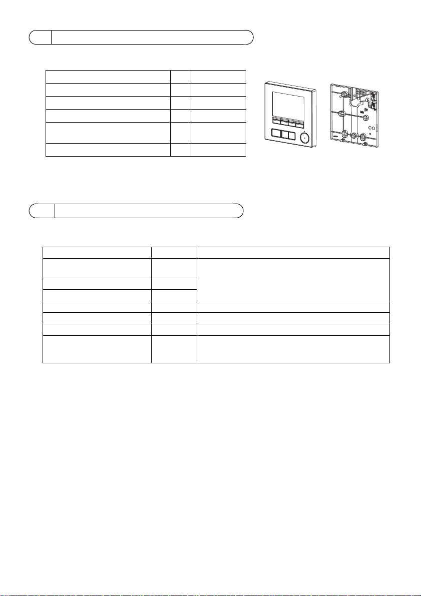
2 Component names and supplied parts
Parts name Qty. Appearance
Remote controller (top case) 1 Right figure *1
Remote controller (bottom case) 1 Right figure *2
Roundhead cross slot screws M4×30 2 *3
Wood screw 4.1×16
(for direct wall installation)
2*3
Simple Manual 1
Bottom case *2Top case *1
The following parts are included in the box.
*3 ISO metric screw thread
*4 Remote controller cable is not included.
3 Field-supplied parts/Required tools
(1) Field-supplied parts
The following parts are field-supplied parts.
Parts name Qty. Notes
Double switch box or 86type
switch box
Thin metal conduit Necessary
Lock nut and bushing Necessary
Cable cover Necessary Required for routing remote controller cable along a wall
Putty Reasonable
Molly anchor Necessary
Remote controller cable
(Use a 0.3 mm² (AWG22) 2-core
sheathed cable.)
1 Not required for direct wall installation
Necessary
(2) Field-supplied tools
• Flat-tip screwdriver (Width: 3 - 5 mm (1/8 - 7/32 inch))
• Nipper
• Miscellaneous tools
– 5 –
Page 6
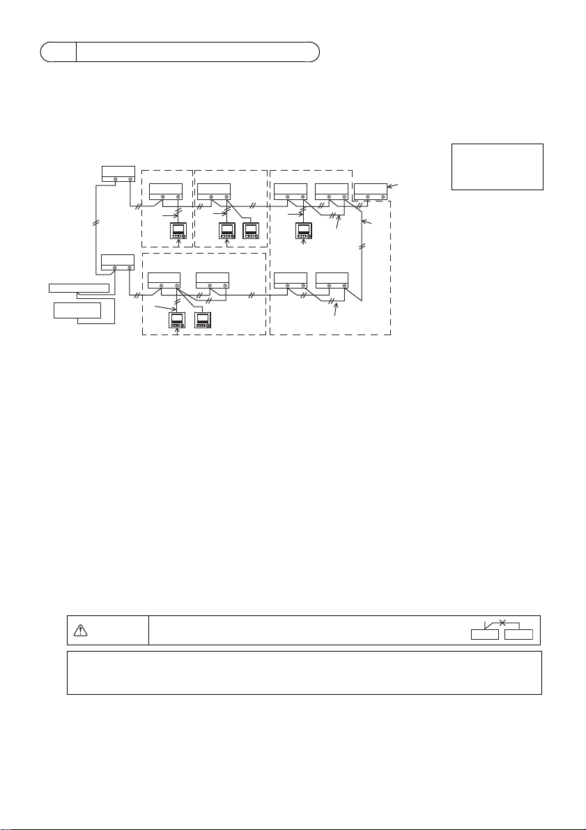
4 How To Wire Transmission Line
TB5 TB15
TB5 TB15
bb
TB5 TB15
c
TB5 TB15
b
TB5 TB15
b
TB5 TB15
b
TB5 TB15
b
TB7 TB3
TB5 TB15
TB5 TB15
TB7 TB3
(1)
(1)
(3)
(3)
(3)
(3)
(2)
(2)
(2)
(4)
(1)
(1)
a
a
dd d
d
bb
f
g
e
e
Address = 51
Address = 01 Address = 02
Address = 55
Address = 08
Address = 07
Address = 03
Address = 04 Address = 09
Address = 06
Address = 05
Group 01 Group 02 Group 03
Group 04
ed
NOTE: When interlocking the MA remote controller with a LOSSNAY or OA processing unit,
always set the address of all the indoor units in the group and the address of the
LOSSNAY or OA processing unit.
The wiring is different when the remote controller is connected to a CITY MULTI control system (“-A”
type and later) and when it is connected to a Mr. SLIM air conditioner (A control type). The wiring also
differs with the system configuration. Check the system used.
1. Connecting to CITY MULTI control system
The numbers (1) to (4) in the figure correspond to items (1) to (4) in the following description.
Connect to TB15
on the indoor unit.
a Outdoor unit
b Indoor unit
c LOSSNAY or
OA processing unit
d Main Remote Controller
e Sub Remote Controller
f Central controller
g Power supply unit for
transmission line
(1) Wiring from the remote controller
• Connect to the MA remote controller terminal block (TB15) on the indoor unit.
• The terminal block has no polarity. Connect to the terminal block at the bottom of the remote
controller case.
(2) Operating in a group (Groups 03, and 04 above)
• Interconnect the MA remote controller terminal block (TB15) of the indoor units you want to
operate as a group, and connect the MA remote controller to that point.
• When the remote controller is used in combination with the system controller as shown in the
figure above, group setting at the system controller (central controller in the figure above) is
necessary.
(3) Number of connectable remote controllers
• A main remote controller and one sub remote controller, a total of two, can be connected to a
group made up of indoor units.
(4) To interlock to a LOSSNAY or OA processing unit, make the following settings using the remote
controller. (For a description of how to set an interlock, see section 10 “Service menu” (5)
“LOSSNAY setting”.)
Set the LOSSNAY or OA processing unit address and the address of all the indoor units you want
to interlock.
(5) Total length of remote controller wiring
• The MA Remote Controller can be wired up to 200 m (656 ft).
CAUTION
Remote controllers cannot be wired together. Only one wire
can be connected to the remote controller terminal block.
– 6 –
Page 7
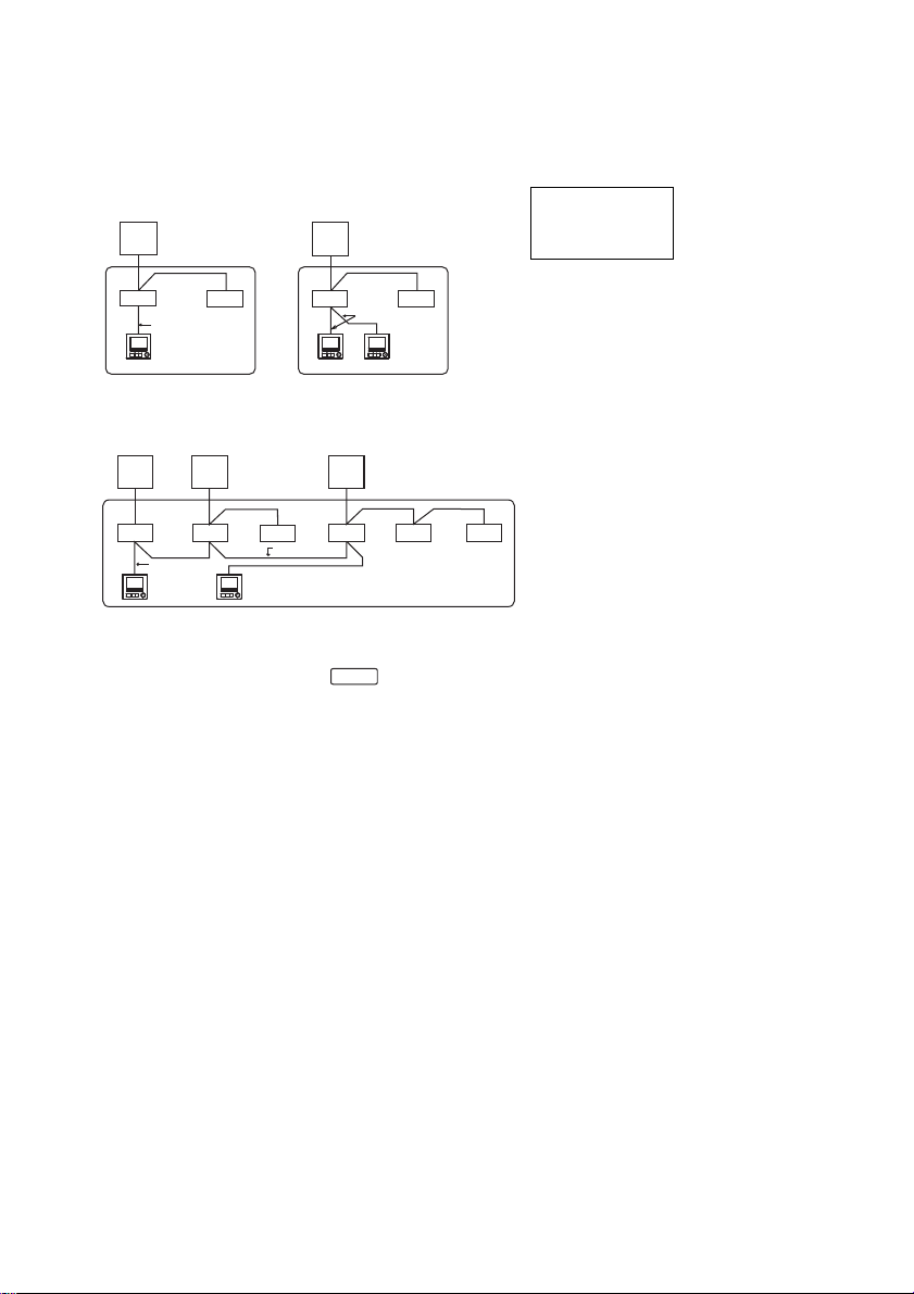
2. Connecting to Mr. SLIM air conditioner
(1)
TB5
TB4
TB1
TB4
(3)
(3)
(1)
TB4
TB4
TB5
TB1
a
bb
d
a
bb
de
(3)
Refrigerant
address = 00
Simultaneous twin Simultaneous twin
Refrigerant
address = 00
Standard 1:1 Simultaneous twin
Simultaneous triple
Refrigerant
address = 01
(Sub)
Refrigerant
address = 00
(Main)
Refrigerant
address = 02
(Sub)
The remote controller wiring depends on the system configuration. Check the system configuration.
Wire the remote controller as shown in the example below.
The numbers (1) to (3) in the figure correspond to items (1) to (3) in the following description.
[1] Connecting the remote controller for each refrigerant system (Standard 1:1, simultaneous twin,
simultaneous triple, simultaneous four)
Connect to TB5
on the indoor unit.
[2] When grouping by different refrigerant systems
aa a
TB1 TB1 TB1
TB4
bbbbbb
TB5
(2)
TB5
(1)
(3)
d
TB4TB4
TB4
(2)
TB5
TB4
TB4
a Outdoor unit
b Indoor unit
d Main Remote Controller
e Sub Remote Controller
* Set the refrigerant address using the outdoor unit dip switches. (For more information, refer to the
outdoor unit installation manual.)
* All the indoor units enclosed in are controlled as one group.
(1) Wiring from remote controller
• Connect to indoor unit TB5 (remote controller terminal block). (The terminal block has no polarity.)
• For simultaneous multi type, when mixing various types of indoor units, always connect the
remote controller to the indoor unit with the most functions (wind velocity, vane, louver, etc.).
(2) When grouping with difference refrigerant systems
• Group using the remote controller wiring. Connect the remote controller to an arbitrary indoor unit
of each refrigerant system you want to group.
• When mixing different types of indoor units in the same group, always make the outdoor unit
connecting the indoor unit with the most functions (wind velocity, vane, louver, etc.) the Main unit
(refrigerant address = 00). Also, when the Main unit is the simultaneous multi type, always satisfy
the conditions of (1) above.
• The MA Remote Controller can control up to 16 refrigerant systems as one group.
(3) Up to two remote controllers can be connected to one group
• When only one remote controller is connected to one group, set it as the Main controller. When
two remote controllers are connected to one group, set the Main remote controller and Sub
remote controller. (For a description of how to set the Main/Sub setting, refer to the section on
initial setting in this manual.)
– 7 –
Page 8
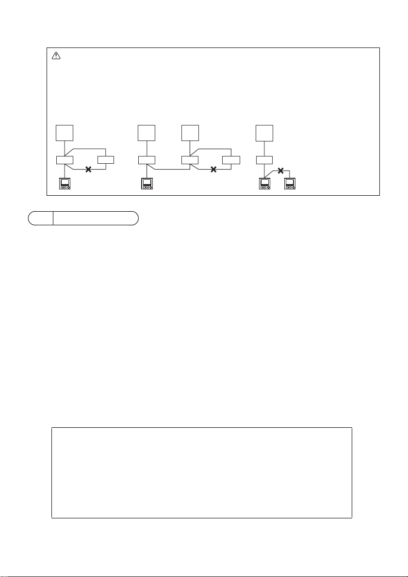
(4) Total length of remote controller wiring
TB4
TB4
TB4
TB4
TB4
TB4
TB1
TB1 TB1
TB1
TB5
TB5
TB5
TB5 TB5 TB5
a
bbb bbb
aa a
dd de
Refrigerant
address = 00
Refrigerant
address = 00
Refrigerant
address = 01
Refrigerant
address = 00
Simultaneous twin Standard 1:1 Simultaneous twin Standard 1:1
■ Discrepancy between the indoor temperature measured at the wall and the actual
indoor temperature may occur.
If the following conditions are met, the use of the temperature sensor on the indoor unit is
recommended.
• Supply air does not reach to the wall easily where the remote controller is installed due to
improper airflow distribution.
• There is a great discrepancy between the wall temperature and the actual indoor
temperature.
• The back side of the wall is directly exposed to the outside air.
Note: When temperature changes rapidly, the temperature may not be detected accurately.
Important
• The MA Remote Controller can be wired up to 450 m (1476 ft).
CAUTION - The wiring cannot be connected to TB5 of the indoor unit of the same
refrigerant system. If so connected, the system will not operate normally.
- Remote controllers cannot be wired together. Only one wire can be connected
to the remote controller terminal block.
- When connecting to TB5, connect up to two wires of the same size to one
terminal block.
a Outdoor unit
b Indoor unit
d Main Remote Controller
e Sub Remote Controller
5 How To Install
This remote controller is for the wall installation. It can be installed either in the switch box or directly
on the wall. When performing direct wall installation, wires can be thread through either back or top of
the remote controller.
(1) Selecting an installation site
Install the remote controller (switch box) on the site where the following conditions are met.
(a) For connection to the indoor unit with an Auto descending panel, a place where people can check
the Auto descending panel operation of the indoor unit while they are operating the remote
controller (Refer to the indoor unit Instructions Book for how to operate Auto descending panel.)
(b) A flat surface
(c) A place where the remote controller can measure the accurate indoor temperature
Sensors to monitor indoor temperature are on the indoor unit and on the remote controller. When
the room temperature is monitored with the sensor on the remote controller, the built-in sensor on
the remote controller monitors the room temperature. When using the sensor on the remote
controller, follow the instructions below.
• To monitor the accurate indoor temperature, install the remote controller away from direct
sunlight, heat sources, and the supply air outlet of the air conditioner.
• Install the remote controller in a location that allows the sensor to measure the representative
room temperature.
• Install the remote controller where no wires are routed around the temperature sensor on the
controller. (If wires are routed, the sensor cannot measure accurate indoor temperature.)
– 8 –
Page 9
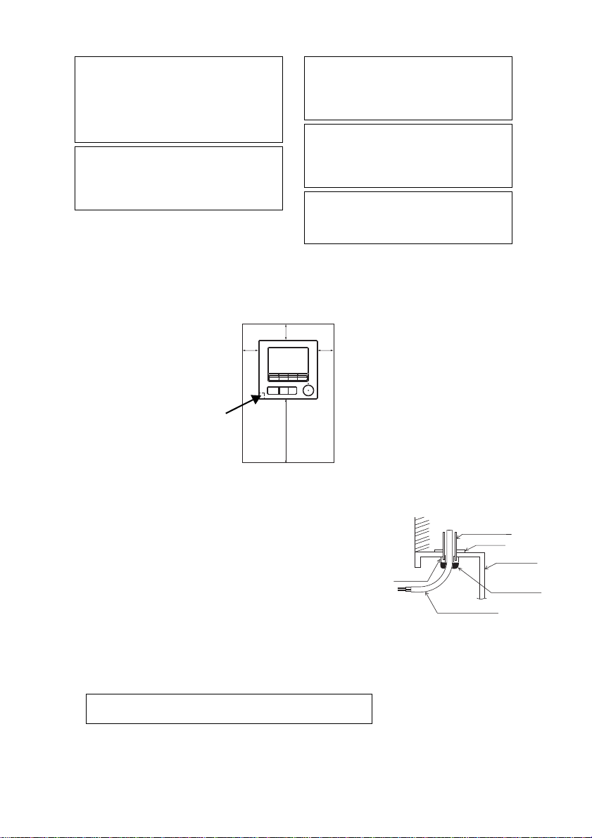
(2) Installation space
Do not install the controller in a place where
the difference between the remote controller
surface temperature and the actual room
temperature will be great.
If the temperature difference is too high,
room temperature may not be adequately
controlled.
To reduce the risk of malfunctions, do not
install the controller in a place where water
or oil may come into contact with the
controller, or in a condensing or corrosive
environments.
To avoid deformation and malfunction, do
not install the remote controller in direct
sunlight or where the ambient temperature
may exceed 40ºC (104ºF) or drop below 0ºC
(32ºF).
To reduce the risk of malfunctions and
damage to the controller, avoid installing the
remote controller on an electrically
conductive surface, such as an unpainted
metal sheet.
Refer to either of the following manuals for
temperature sensor setting: indoor unit
Installation Manual for CITY MULTI; this
manual for Mr. SLIM.
Temperature sensor
Unit: mm (in)
External dimensions of remote controller
Minimum required space
around the remote
controller
Wall
Conduit tube
Locknut
Switch box
Seal the gap
with putty.
Remote
controller cable
Bushing
To reduce the risk of electric shock, malfunctions, or fire, seal
the gap between the cables and cable access holes with putty.
Leave a space around the remote controller as shown in the figure shown below, regardless of
whether the controller is installed in the switch box or directly on the wall. Removing the remote
controller will not be easy with insufficient space.
Also, leave an operating space in front of the remote controller.
(3) Installation work
Controller can be installed either in the switch box or directly on the
wall. Perform the installation properly according to the installation
method.
1 Drill a hole in the wall.
■ Installation using a switch box
• Drill a hole in the wall, and install the switch box on the wall.
• Connect the switch box to the conduit tube.
■ Direct wall installation
• Drill a hole in the wall, and thread the cable through it.
2 Seal the cable access hole with putty.
■ Installation using a switch box
• Seal the remote controller cable access hole at the
connection of switch box and conduit tube with putty.
30 (1-3/16)
30
(1-3/16)
– 9 –
120 (4-3/4)
30
(1-3/16)
Page 10
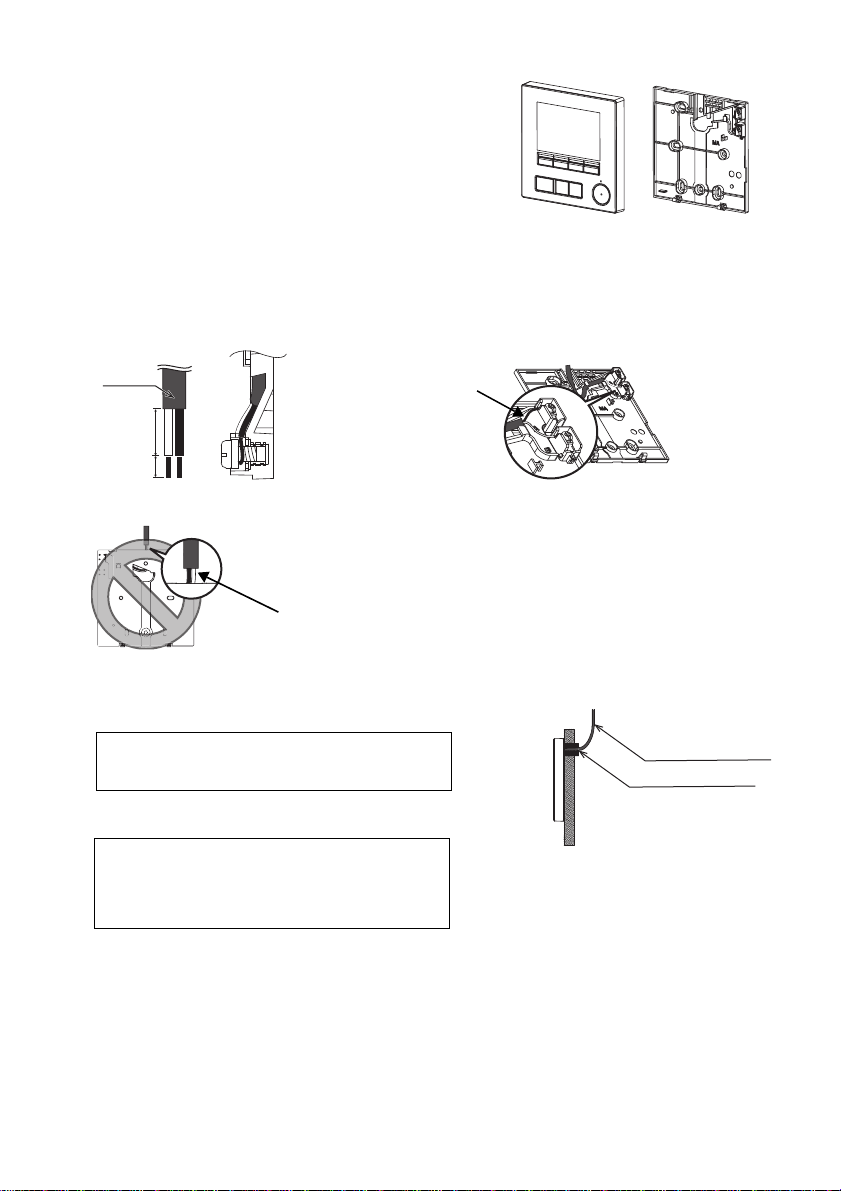
3 Prepare the bottom case of the remote controller.
Top case Bottom case
Sheath
Unit: mm (in)
Connect the cable.
(non-polarized)
2-core wire must not be
seen on the back.
Seal the gap with putty.
Route the cable behind
the remote controller.
Remote controller cable
To reduce the risk of electric shock, shorting, or
malfunctions, keep wire pieces and sheath shavings
out of the terminal block.
Do not use solderless terminals to connect cables to
the terminal block.
Solderless terminals may come in contact with the
circuit board and cause malfunctions or damage the
controller cover.
Important
4 Connect the remote controller cable to the terminal block on the bottom case.
Peel off the remote controller cable sheath as shown below to connect to the terminal block properly.
Secure the remote controller cable so that the peeled part of the cable will fit into the case.
15 (19/32)
6 (1/4)
■ Direct wall installation
• Seal the hole through which the cable is threaded with putty.
– 10 –
Page 11

5 Install the bottom case.
Remote controller
cable
Refer to 4.
Refer to 2.
Double switch box
Roundhead cross
slot screws
Seal the cable access
hole with putty.
Refer to 4.
Wood
screws
Remote controller
cable
Thread the cable
through the groove.
To avoid damage to the controller, do not
overtighten the screws.
To avoid damage to the controller, do not make
holes on the controller cover.
Important
Notice
To prevent damage to the circuit board,
remove the front cover from the top case
before cutting out a cable access hole.
Note that accidentally touching the circuit
board may damage the circuit board when
cutting out a cable access hole.
Connect the connector.
To prevent malfunctions, do not remove the
protective sheet or the circuit board from the
top case.
To prevent cable breakage and malfunctions,
do not hang the top controller casing hang by
the cable as shown in the figure above.
Important
■ Installation using a switch box
• Secure at least two corners of the switch box with screws.
■ Direct wall installation
• Thread the cable through the groove.
• Secure at least two corners of the remote controller with screws.
• Be sure to secure top-left and bottom-right corners of the remote controller (viewed from the
front) to prevent it from lifting. (Use molly anchor etc.)
■ Installation using a switch box ■ Direct wall installation
6 Cut out the cable access hole.
■ Direct wall installation (when running the cable along the wall)
• Cut out the thin-wall part on the cover (the shaded area in the right
figure) with a nipper.
• Thread the cable from the groove behind the bottom case through
this access hole.
7 Connect the connector to the top case.
Connect the connector on the bottom case to the socket on the top case.
– 11 –
Page 12

8 Insert the wires into the clamp.
Insert the wires.
Clamp
Hold the wires in place with the clamp to
prevent undue force from being applied to
the terminal block and causing cable
breakage.
Important
Wall
Should not
be lifted.
When attaching the top casing to the bottom
casing, push it until it they click into place.
If they are not properly locked into place,
they may fall, causing personal injury,
controller damage, or malfunctions.
Important
Seal the gap
with putty.
Use a cable
cover.
Thread the cable through the top of the
remote controller.
9 Install the top case on the bottom case.
Two mounting tabs are at the top of the top case.
Hook those two tabs onto the bottom case, and click the top case into place. Check that the case is
securely installed and not lifted.
■ Direct wall installation (when running the cable along the wall)
• Thread the cable through the access hole at the top of the remote controller.
• Seal the cut-out part of the cover with putty.
• Use a cable cover.
– 12 –
Page 13

• Uninstalling the top case
To prevent damage to the controller casing,
do not force the flat-tip screwdriver to turn
with its tip inserted in the slot.
Do not insert the flat-tip screwdriver too far.
Doing so will damage the circuit board.
To prevent damage to the controller casing,
use a flat-head screwdriver with a blade
width of 3-5 mm (1/8-7/32 inch).
Important
1 Uninstalling the top case
Insert a flat-tip screwdriver with a blade width of 3-5 mm (1/8-7/32 inch) into the latches at the bottom
of the remote controller and lift the latches. Then, pull up the top case.
■ At the time of factory shipment, protective sheet is on the operation interface of the front
cover. Peel off the protective sheet on the operation interface prior to use.
– 13 –
Page 14

6 Remote controller button functions
(5) SELECT button
(4) RETURN button
(3) MENU button
(7) Backlit LCD
(2) Function buttons
F1, F2, F3, and F4 from the left
(6) Operation indicator
(1) ON/OFF button
(1) ON/OFF button
Use to turn ON/OFF the indoor unit.
(2) Function buttons
Use to select the operation mode or to set the
temperature and fan speed on the Main display.
Use to select items on other screens.
(3) MENU button
Use to bring up the Main menu.
(4) RETURN button
Use to return to the previous screen.
(5) SELECT button
Use to jump to the setting screen or to save the
settings.
(6) Operation indicator
Stays lit during normal operation. Blinks during
startup and when an error occurs.
(7) Backlit LCD
Dot display. When the backlight is off, pressing
any button turns the backlight on and it will stay
lit for a certain period of time depending on the
screen. Performing any button operation keeps
the backlight on.
Pressing the MENU button will bring up the Main
menu as shown below.
Operation menu *1
Timer menu *1
Energy saving menu *1
Initial setting menu *2*3
Maintenance menu *1
Service menu *2*3
*1 Refer to the Instructions Book for details.
*2 Explained in this manual.
*3 If no buttons are pressed for 10 minutes on the
initial setting screens, or 2 hours on the service
screens (10 minutes on some screens), the
screen will automatically return to the Main
display. Any settings that have not been saved
will be lost.
The available items on the menu depend on the
connected indoor unit model. For items not
described in the manuals that are enclosed with
the MA Remote Controller, refer to the manuals
that came with the air conditioning units.
Note: When the backlight is off, pressing any
button turns the backlight on and does not
perform its function. (except for the ON/OFF
button)
– 14 –
Page 15

Button operations on the Main menu
Cursor
Move the cursor to the desired function with the F2
and F3 buttons, and press the SELECT button to go
to the next page. Password may be required.
Button function guide will appear at the bottom of the
screens.
F1 F2 F3 F4
Note: When the power is on for the first time, the Language selection screen
will be displayed. Refer to section 9 (5) under “Display setting menu”.
Select a desired language. The system will not start-up without language
selection.
Note: Refer to the Instruction Book
for the icons on the display.
7 Turning on the power
Make sure that the MA remote controller is properly installed according to the instructions in the
Installation Manual and that the indoor and outdoor unit installation has been completed before
turning on the power.
(1) When the power is turned on, the following screen will appear.
Normal start up (indicating the
percentage of process completion)
(2) Main display
After the successful startup, the Main display will appear. The Main display can be displayed in two
different modes: “Full” and “Basic.” Refer to section 9 “Initial settings” for how to select the display
mode. (The factory setting is “Full.”)
Main display in the Full mode
(while the unit is not in operation)
Main display in the Full mode
(while the unit is in operation)
– 15 –
Page 16

8 Test run
Note: Maintenance password is required.
Note: Refer to section 10 “Service menu” for information about the maintenance password.
Note: Administrator password is required.
Note: The initial administrator password
is “0000.” Refer to section (4)
“Administrator password setting”
for how to change the password.
(1) Read the section about Test run in the indoor unit Installation Manual before performing a test run.
(2) At the Main display, press the Setting button and select Service>Test run>Test run.
(3) Press the ON/OFF button to cancel the test run if necessary.
(4) Refer to the indoor unit Installation Manual for the detailed information about test run and for
how to handle the errors that occur during a test run.
9 Initial settings (Remote controller settings)
From the Main display, select Main menu>Initial setting, and make the remote controller settings on
the screen that appears.
Basic setting menu
•Main/Sub
•Clock
• Daylight saving time
• Administrator password
Display setting menu
• Main display
• Remote controller display
details setting
• Contrast•Brightness
• Language selection
Basic setting menu
(1) Main/Sub setting
When connecting two remote controllers, one of them needs to be designated as a sub controller.
[Button operation]
1 When the F3 or F4 button is pressed, the currently selected setting will
appear highlighted. Select “Sub”, and press the SELECT button to save
the change.
2 Press the MENU button to return to the Main menu screen. (This button
always brings up the Main menu screen.)
Operation setting menu
• Auto mode
(2) Clock setting
[Button operation]
1 Move the cursor with the F1 or F2 button to the desired item.
2 Change the date and time with the F3 or F4 button, and press the
SELECT button to save the change. The change will be reflected on
the clock display on the Status display and the Main display.
Note: Clock setting is necessary for time display, weekly timer, timer setting and
error history. Make sure to perform clock setting when the unit is used for
the first time or has not used for a long time.
Note: If a given system has no system controllers, the clock time will not
automatically be corrected. In this case, periodically correct the clock time.
– 16 –
Page 17

(3) Daylight saving time
The start/end time for daylight saving time can be set. The daylight saving
time function will be activated based on the setting contents.
• If a given system has a system controller, disable this setting to keep
the correct time.
• At the beginning and the end of daylight saving time, the timer may go
into action twice or not at all.
• This function will not work unless the clock has been set.
[Button operation]
1 The daylight saving time function can be activated/deactivated or the
start/end times can be set by using the F1 through F4 buttons.
•DST
Select “Yes” to activate the daylight saving time, or select “No” to
deactivate.
• Date(Start)
Set the start day of the week, week number, and month for daylight
saving time.
•Start time
Set the start time for daylight saving time.
• Forward to
Set the time when the clock is to be set forward to at the start time
above.
• Date(End) (2nd page)
Set the end day of the week, week number, and month for daylight
saving time.
• End time (2nd page)
Set the end time for daylight saving time.
• Backward to (2nd page)
Set the time when the clock is to be set backward to at the end time
above.
2 Press the SELECT button to save the setting.
* If “5th” is selected for the week number and the 5th week does not exist in the
selected month of the year, the setting is considered to be “4th.”
(4) Administrator password setting
[Button operation]
1 A window to enter a new password will appear. Enter a new password,
and press the SELECT button.
2 Press the F4 button (OK) on the password change confirmation screen
to save the change. Press the F3 button (Cancel) to cancel the change.
Note: The initial administrator password is “0000.” Change the default password
as necessary to prevent unauthorized access. Have the password
available for those who need it.
Note: If you forget your administrator password, you can initialize the password
to the default password “0000” by pressing and holding the F1 button for
ten seconds on the administrator password setting screen.
Note: The administrator password is required to make the settings for the
following items.
· Timer setting · Weekly timer setting · Energy-save setting
· Outdoor unit silent mode setting · Restriction setting
· Night setback setting · Initial setting
Refer to the Instruction Book that came with the remote controller for the
detailed information about how to make the settings for these items.
– 17 –
Page 18

Display setting menu
Full mode (Example)
Basic mode (Example)
(1) Main display setting
[Button operation]
Move the cursor to “Full/Basic,” and use the F3 or F4 button to select the display mode “Full” or
“Basic.” (The factory setting is “Full.”)
Note: This setting is only for the Main display. In the Basic mode, icons that indicate control status
on timer and schedule settings will not appear on the display. Vane, louver, and ventilation
settings or room temperature will not appear, either.
(2) Black and white inversion setting
Move the cursor to “B&W inversion” and use the F3 or F4 button to select
the display mode “Yes” or “No.” (The factory setting is “No.”)
Selecting “Yes” will invert the colors of the display, turning white
background to black and black characters to white as shown at right.
(3) Remote controller display details setting
Make the settings for the remote-controller-related items as necessary.
Press the SELECT button to save the changes.
– 18 –
Page 19

[1] Clock display
[Button operation]
1 Select “Clock” from the display details setting screen, and press the
F4 button (Change) to bring up the clock display setting screen.
2 Use the F1 through F4 buttons to select “Yes” (display) or “No” (non-
display) and its format for the Status display and the Main display.
3 Save the settings with the SELECT button. (The factory settings are
“Yes” (display) and “24 h” format.)
Clock display: Yes (Time is displayed on the Status display and the Main display.)
Display format: 24-hour format
AM/PM display (Effective when the display format is 12-hour): AM/PM before the time
Note: Time display format will also be reflected on the timer and schedule setting display. The time is displayed
as shown below.
12-hour format: AM12:00 ~ AM1:00 ~ PM12:00 ~ PM1:00 ~ PM11:59
24-hour format: 0:00 ~ 1:00 ~ 12:00 ~ 13:00 ~ 23:59
No (Time is not displayed on the Status display and the Main display.)
12-hour format
AM/PM after the time
[2] Temperature unit setting
[Button operation]
Move the cursor to “Temperature” from the display details setting screen,
and select the desired temperature unit with the F3 or F4 button. (The
factory setting is Centigrade (ºC).)
• ºC: Temperature is displayed in Centigrade. Temperature is displayed
in 0.5- or 1-degree increments, depending on the model of indoor
units.
• ºF: Temperature is displayed in Fahrenheit.
• 1 ºC: Temperature is displayed in Centigrade in 1-degree increments.
[3] Room temperature display
[Button operation]
Move the cursor to “Room temp.” on the display details setting screen, and select the desired
setting with the F3 or F4 button.
(The factory setting is “Yes”.)
• Yes: Room temperature appears on the Main display.
• No: Room temperature does not appear on the Main display.
Note: Even when “Yes” is set, the room temperature is not displayed on the Main display in the “Basic” mode.
[4] Auto (single set point) mode display setting
[Button operation]
Move the cursor to “Auto mode” from the display details setting screen, and select the desired
mode with the F3 or F4 button. (The factory setting is “Yes.”)
• Yes: “Auto Cool” or “Auto Heat” is displayed during operation in the Auto (single set point) mode.
• No: Only “Auto” is displayed during operation in the Auto (single set point) mode.
– 19 –
Page 20

[5] Backlight
The backlight lighting-up time can be set.
[Button operation]
Move the cursor to “Backlight” from the display details setting screen, and select the desired time
(5/10/20/30/60 seconds) with the F4 button. (The factory setting is “30” seconds.)
Note: This setting is effective on the Status display and the Main display.
[6] LED lighting
The LED lighting can be set to either “Yes” (On) or “No” (Off). (The
factory setting is “Yes”.)
When “No” is selected, the LED will not light up even during the normal
operation.
(4) Contrast•Brightness
[Button operation]
Select the desired brightness for the remote controller LCD with the F1
and F2 buttons.
Adjust the contrast with the F3 or F4 button. The current level is indicated
with a triangle.
Note: Adjust the contrast and brightness to improve viewing in different lighting
conditions or installation locations. This setting can not improve viewing
from all directions.
(5) Language selection
[Button operation]
Move the cursor to the language you desire with the F1 through F4
buttons.
Press the SELECT button to save the setting.
– 20 –
Page 21

Operation setting menu
Note: Maintenance password is required.
(1) Auto mode setting
[Button operation]
Whether or not to use the Auto (single set point) or Auto (dual set points)
mode can be selected by using the F3 or F4 button. This setting is valid
only when indoor units with the Auto mode function are connected.
(The factory setting is “Yes”.)
Press the SELECT button to save the changes made.
• Yes: The Auto mode can be selected in the operation mode setting.
• No: The Auto mode cannot be selected in the operation mode setting.
10 Service menu
At the Main display, press the Setting button and select “Service” to make the maintenance settings.
When the Service menu is selected, a window will appear asking for the password.
To enter the current maintenance password (4 numerical digits), move the cursor to the digit you want
to change with the F1 or F2 button, and set each number (0 through 9) with the F3 or F4 button. Then,
press the SELECT button.
Note: The initial maintenance password is “9999.” Change the default password
as necessary to prevent unauthorized access. Have the password
available for those who need it.
Note: If you forget your maintenance password, you can initialize the password
to the default password “9999” by pressing and holding the F1 button for
ten seconds on the maintenance password setting screen.
Note: Air conditioning units may need to be stopped to make certain settings.
There may be some settings that cannot be made when the system is
centrally controlled.
– 21 –
Page 22

(1) Test run (CITY MULTI and Mr. SLIM)
Select “Test run” from the Service menu to bring up the Test run menu.
• Test run: Select this option to perform a test run.
• Drain pump test run: Select this option to perform a test run on the
drain pump on the indoor unit.
Applicable only to the type of indoor units that support the test run
function.
Note: Refer to the indoor unit Installation Manual for the detailed information
about test run.
(2) Input maintenance information (CITY MULTI and Mr. SLIM)
Select “Input maintenance info.” from the Service menu to bring up the
Maintenance information screen. Refer to the indoor unit Installation
Manual for how to make the settings.
Note: The following settings can be made from the Maintenance information
screen.
·Registering model names and serial numbers
Enter the model names and serial numbers of outdoor and indoor units.
The information entered will appear on the Error information screen.
Model names can have up to 18 characters, and the serial numbers can
have up to 8 characters.
·Registering dealer information
Enter phone number of a dealer. The entered information will appear on
the Error information screen. Phone number can have up to 13
characters.
·Initializing maintenance information
Select the desired item to initialize the model name, serial number, and
dealer information settings.
(3) Function setting (CITY MULTI)
Make the settings for the indoor unit functions via the remote controller as
necessary.
Select “Function setting” from the Settings menu to bring up the Function
setting screen.
[Button operation]
1 The Function setting screen will appear.
Press the F1 or F2 button to move the cursor to one of the following: M-NET address, function
setting number, or setting value. Then, press the F3 or F4 button to change the settings to the
desired settings.
2 Once the settings have been completed, press the SELECT button.
A screen will appear that indicates that the settings information is being
sent.
To check the current settings of a given unit, enter the setting for its MNET address and function setting number, select Conf for the Function,
and press the SELECT button.
A screen will appear that indicates that the settings are being searched
for. When the search is done, the current settings will appear.
3 When the settings information has been sent, a screen will appear that
indicates its completion.
To make additional settings, press the RETURN button to return to the
screen shown in Step 2 above. Set the function numbers for other
indoor units by following the same steps.
– 22 –
Page 23

Note:
· Refer to the indoor unit Installation Manual for information about the factory settings of indoor units,
function setting numbers, and setting values.
· Be sure to write down the settings for all functions if any of the initial settings has been changed after the
completion of installation work.
(4) Function setting (Mr. SLIM)
Make the settings for the indoor unit functions via the remote controller as
necessary.
Select “Function setting” from the Settings menu to bring up the Function
setting screen.
[Button operation]
1 Set the indoor unit refrigerant addresses and unit numbers with the F1 through F4 buttons, and
then press the SELECT button to confirm the current setting.
2 When data collection from the indoor units is completed, the current
settings appears highlighted. Non-highlighted items indicate that no
function settings are made. Screen appearance varies depending on
the “Unit No.” setting.
Common items
3 Use the F1 or F2 button to move the cursor to select the mode number,
and change the setting number with the F3 or F4 button.
Individual items
(Unit No. 1 through 4)
4 When the settings are completed, press the SELECT button to send the
setting data from the remote controller to the indoor units.
5 When the transmission is successfully completed, the screen will return
to the Function setting screen.
Note:
· Make the function settings shown in Table 1 on Mr. SLIM units as necessary.
· Refer to the Instructions Book when it is necessary to set the settings for CITY MULTI units.
· Table 1 summarizes the setting options for each mode number. Refer to the indoor unit Installation
Manual for the detailed information about initial settings, mode numbers, and setting numbers for the
indoor units.
· Be sure to write down the settings for all functions if any of the initial settings has been changed after the
completion of installation work.
– 23 –
Page 24

Table1. Function setting options
Mode No. Mode Settings Setting No. Unit numbers
01 Automatic recovery after
power failure
02 Thermistor selection
(indoor temperature
detection)
03 LOSSNAY connection Not connected 1
04 Power voltage 240 V 1
05 Auto mode Enable (Automatically the unit
07 Filter sign 100 hours 1 Set “1, 2, 3, 4, or All” for the Unit
08 Fan speed Silent mode (or standard) 1
09 Outlet 4 directional 1
10 Optional parts
(High-efficiency filter)
11 Vane No vanes (or the vane setting No.3 is
Disable 1 Set “Grp.” for the Unit number.
Enable (Four minutes of standby time
is required after the restoration of
power.)
Average temperature reading of the
indoor units in operation
Thermistor on the indoor unit to which
the remote controller is connected
(fixed)
Built-in sensor on the remote controller 3
Connected (without outdoor air intake
by the indoor units )
Connected (with outdoor air intake by
the indoor units )
220 V, 230 V 2
achieves effective energy saving
operation.)
Disable 2
2500 hours 2
Not displayed 3
Standard (or High ceiling 1) 2
High ceiling (or High ceiling 2) 3
3 directional 2
2 directional 3
No 1
Yes 2
effective.)
Equipped with vanes (The vane
setting No.1 is effective.)
Equipped with vanes (The vane
setting No.2 is effective.)
These settings apply to all the
2
connected indoor units.
1
2
2
3
1
number.
These settings apply to each indoor
unit.
·If “1, 2, 3, or 4” is set for the Unit
number, the settings apply only to
the specified indoor unit regardless
of the number of connected indoor
units (one through four units).
·If “All” is set for the Unit number, the
settings apply to all the connected
indoor units regardless of the
number of connected i ndoor units
(one through four units).
1
2
3
(5) LOSSNAY setting (CITY MULTI only)
This setting is required only when the operation of CITY MULTI units is interlocked with LOSSNAY
units. This setting is not available for the Mr. SLIM units. Interlock settings can be made for the indoor
unit to which the remote controller is connected. (They can also be confirmed or deleted.)
Note:
· Use the centralized controller to make the settings if it is connected.
· To interlock the operation of the indoor units with the LOSSNAY units, be sure to interlock the addresses of ALL
indoor units in the group and that of the LOSSNAY unit.
[Button operation]
1 When “Lossnay” on the Settings menu is selected, the remote controller
will automatically begin searching for the registered LOSSNAY
addresses of the currently connected indoor unit.
– 24 –
Page 25

2 When the search is completed, the smallest address of the indoor units
that are connected to the remote controller and the address of the
interlocked LOSSNAY unit will appear. “--” will appear if no LOSSNAY
unit is interlocked with the indoor units.
If no settings need to be made, press the RETURN button to go back to
the Settings menu.
To make LOSSNAY interlock setting
3 Enter the addresses of the indoor unit and the
LOSSNAY unit to be interlocked, with the F1
through F4 buttons, select “Set” in the
“Function”, and press the SELECT button to
save the settings. “Sending data” will appear
on the screen. If the setting is successfully
completed, “Setting completed” will appear.
To search for the LOSSNAY address
4 Enter the address of the indoor unit to which
the remote controller is connected, select
“Conf” in the “Function”, and press the
SELECT button. “Collecting data” will appear
on the screen. If the signal is received
correctly, the indoor unit address and
LOSSNAY address will appear. “--” will
appear when no LOSSNAY unit is found.
“Unit not exist” will appear if no indoor units
that are correspond to the entered address
are found.
To delete the interlock setting
5 To delete the interlocked setting between
LOSSNAY unit and the indoor units to which
the remote controller is connected, enter the
indoor unit address and LOSSNAY address
with the F1 through F4 buttons, select “Del.”
in the “Function”, and press the SELECT
button. “Deleting” will appear. The screen will
return to the search result screen if the
deletion is successfully completed. “Unit not
exist” will appear if no indoor units that are
correspond to the entered address are found.
If deletion fails, “Request rejected” will
appear on the screen.
– 25 –
Page 26

(6) Check
Select “Check” on the Service menu to bring up
the Check menu screen.
<Mr. SLIM> <CITY MULTI>
The type of menu that appears depends on the
type of indoor units that are connected (CITY
MULTI or Mr. SLIM).
(When CITY MULTI is connected, only “Error
history” will appear in the menu.)
[Button operation]
1 Error history
Select “Error history” from the Check menu, and press the SELECT
button to view up to 16 error history records. Four records are shown
per page, and the top record on the first page indicates the latest error
record.
[Deleting the error history]
To delete the error history, press the F4 button (Delete) on the screen
that shows error history. A confirmation screen will appear asking if you
want to delete the error history.
Press the F4 button (OK) to delete the error history.
“Error history deleted” will appear on the screen. Press the RETURN
button to go back to the Check menu screen.
2 Other options in the Check menu (Mr. SLIM only)
The following options are also available on the Mr. SLIM units in the Check menu.
• Smooth maintenance
• Request code
These options are available only on the Mr. SLIM units. Refer to the indoor unit Installation Manual
for details.
(7) Diagnostic function
Error history of each unit can be checked via the remote controller.
[Button operation]
1 Select “Self check” from the Diagnosis menu,
<Mr. SLIM> <CITY MULTI>
and press the SELECT button to view the
Self check screen.
2 With the F1 or F2 button, enter the refrigerant
address (Mr. SLIM) or the M-NET address
(CITY MULTI), and press the SELECT
button.
3 Error code, unit number, attribute, and indoor
unit demand signal ON/OFF status at the
contact (CITY MULTI only) will appear. “-” will
appear if no error history is available.
– 26 –
Page 27

<Mr. SLIM> <CITY MULTI>
When there is no error history
[Resetting the error history]
1 Press the F4 button (Reset) on the screen that shows the error history.
A confirmation screen will appear asking if you want to delete the error
history.
2 Press the F4 button (OK) to delete the error history. If deletion fails,
“Request rejected” will appear, and “Unit not exist” will appear if no
indoor units that are correspond to the entered address are found.
(8) Changing the maintenance password
[Button operation]
1 Select “Maintenance password” on the Others menu, and press the
SELECT button to bring up the screen to enter a new password.
2 Move the cursor to the digit you want to change with the F1 or F2
button, and set each digit to the desired number (0 through 9) with the
F3 or F4 button.
3 Press the SELECT button to save the new password.
4 A confirmation screen will appear asking if you want to change the
maintenance password. Press the F4 button (OK) to save the change.
Press the F3 button (Cancel) to cancel the change.
5 “Changes saved” will appear when the password is updated.
6 Press the MENU button to return to the Service menu or press the
RETURN button to go back to the “Maintenance password” screen.
– 27 –
Page 28

(9) Remote controller information
The following information of the remote controller in use can be checked.
• Model name
• Software version
• Serial number
[Button operation]
1 Select “Others” from the Service menu.
2 Select “Remote controller information”.
11 Remote controller check
When the remote controller does not work properly, use the remote controller checking function to
troubleshoot the problem.
(1) Check the remote controller display and see if anything is displayed (including lines). Nothing will
appear on the remote controller display if the correct voltage (8.5-12 VDC) is not supplied to the
remote controller. If this is the case, check the remote controller wiring and indoor units.
[Button operation]
1 Select “Remote controller check” from the Diagnosis menu, and press the SELECT button to start
the remote controller check and see the check results. To cancel the remote controller check and
exit the Remote controller check menu screen, press the MENU or the RETURN button. The
remote controller will not reboot itself.
Select “Remote
controller check”.
OK: No problems are found with the remote controller. Check other parts for problems.
E3, 6832: There is noise on the transmission line, or the indoor unit or another remote controller is faulty. Check
NG (ALL0, ALL1): Send-receive circuit fault. Remote controller needs replacing.
ERC: The number of data errors is the discrepancy between the number of bits in the data transmitted from the
the transmission line and the other remote controllers.
remote controller and that of the data that was actually transmitted over the transmission line. If data errors
are found, check the transmission line for external noise interference.
Remote controller check
results screen
2 If the SELECT button is pressed after the remote controller check results are displayed, remote
controller check will end, and the remote controller will automatically reboot itself.
– 28 –
Page 29

Page 30

Page 31

Page 32

HEAD OFFICE: TOKYO BLDG., 2-7-3, MARUNOUCHI, CHIYODA-KU, TOKYO 100-8310, JAPAN
MANUFACTURER: MITSUBISHI ELECTRIC CORPORATION Air-conditioning & Refrigeration Systems Works
5-66, Tebira 6 Chome, Wakayama-city, 640-8686, Japan
WT09015X01_en
This product is designed and intended for use in the residential,
commercial, and light-industrial environment.
The product at hand is based on the following EU regulations:
• Restriction of Hazardous Substances 2011/65/EU
• Electromagnetic Compatibility Directive 2014/30/EU
 Loading...