

Page 1
SPLIT -TYPE AIR CONDITIONERS
TECHNICAL & SERVICE MANUAL
Air Conditioner Optional Parts
R-Converter Unit
[Model name] [Service Ref.]
PAC-SF29LB PAC-SF29LB
2003
No.OC296
R-Converter Unit
w Refer to the technical & service manuals of the indoor
and outdoor units.
CONTENTS
1. OVERVIEW OF UNITS······································2
2. SPECIFICATIONS·············································8
3. OUTLINES AND DIMENSIONS························9
4. WIRING DIAGRAM·········································10
5.
NECESSARY CONDITIONS FOR SYSTEM CONSTRUCTION
6. TROUBLESHOOTING ····································12
7. ELECTRICAL WORK ······································19
8. REFRIGERANT PIPING··································22
9. PARTS LIST····················································23
···11
Page 2
1 OVERVIEW OF UNITS
SL series
MS series
Outdoor unit
R-Converter Unit
R-Converter Unit
R-Converter Unit
R-Converter Unit
R-Converter Unit
PUMY series
Branching Pipe
Capacity type
Rated capacity
Model
20
25
32
40
50
63
Cooling (kW)
2.2
2.8
3.6
4.5
5.6
7.1
Heating (kW)
2.5
3.2
4.0
5.0
6.3
8.0
SL series
4-way folw
Cassette
Ceiling
—
SLH-1AR1.TH
—
SLH-1.6AR1.TH
SLH-2AR1.TH
—
MS series
Wall Mounted
CITY MULTI indoor Units
(P•FY series)
Remote Controller
Panel SLP-2AL
R-Converter Unit PAC-SF29LB
MSC-07RV-E5, MSH-07RV-A3
MSC-09RV-E5, MSH-09RV-A3
—
MSC-12RV-E5, MSH-12RV-A3
MSH-18RV-E2, MSH-18RV-A2
MSH-24RV-E2, MSH-24TV-A2
+
+
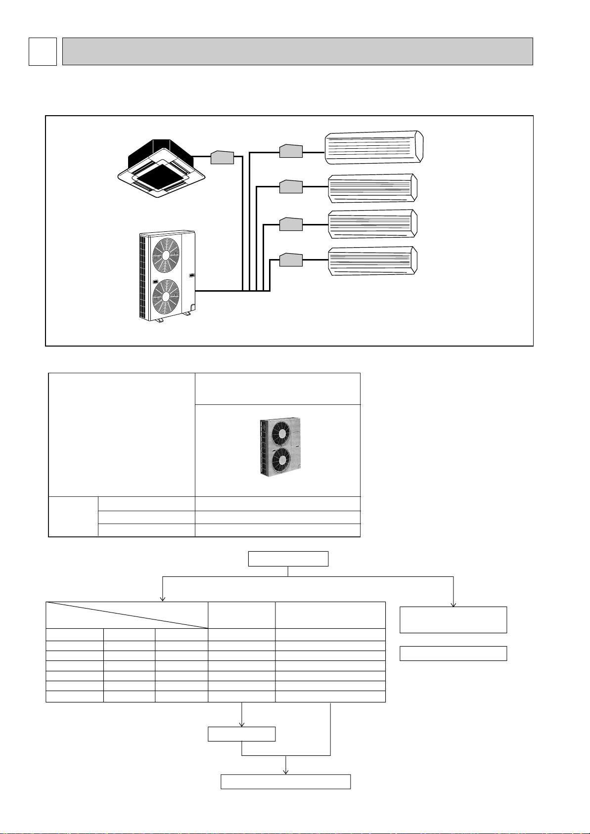
1-1. SYSTEM OUTLINE
1-1-1. System example
1-2. UNIT CONSTRUCTION
Outdoor unit
Indoor unit
that can be
connected
Capacity
Number of units
Total system wide capacity
50~130% of outdoor unit capacity
PUMY-P125VMA
PUMY-P125YMA
Type 20~Type 125
1~8 units
2
Page 3
PAC - SF 29 LB
(Indispensable)
Optional parts
of PAC
Symble of
factory
Lev Box
Design code No.
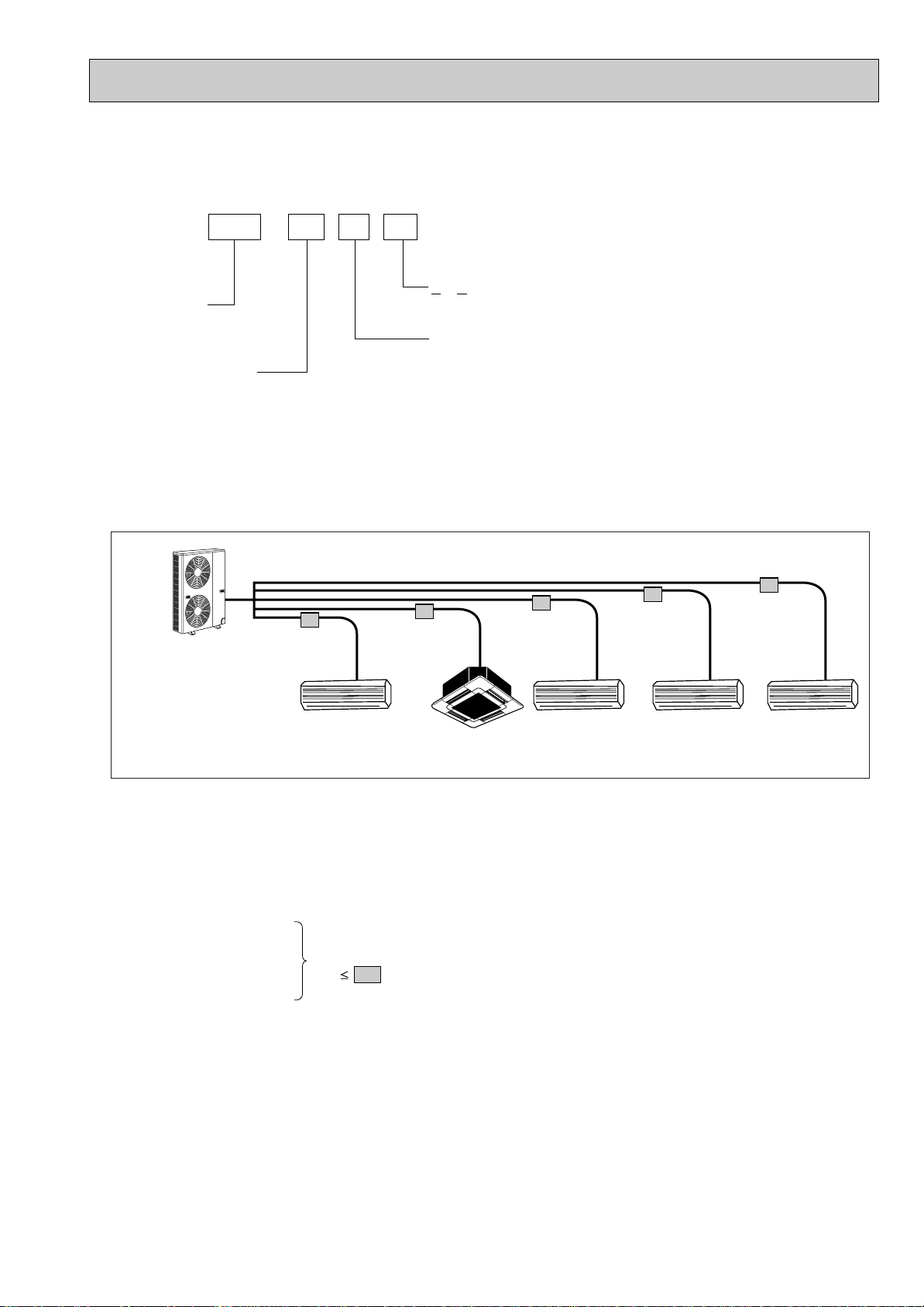
1-3. METHOD FOR IDENTIFYING
PUMY-P125YMA
MSH-18RV SLH-1.6AR MSC-09RV MSC-09RV MSC-07-RV
Living
R-Converter Unit
(PAC-SF29LB)
R-Converter Unit
(PAC-SF29LB)
R-Converter Unit
(PAC-SF29LB)
R-Converter Unit
(PAC-SF29LB)
R-Converter Unit
(PAC-SF29LB)
Bedroom (1) Bedroom (2) Bedroom (3)
Dining
Total rated capacity
160 163
■ R-Converter Unit
1-4. TYPICAL COMBINATION EXAMPLE
■ Verification
The rated capacity should be determined by observing the below. The unit’s quantities are limited in 1 to 8 units. For
the next step, make sure that the selected total indoor unit capacity is in a range of 63 ~ 163.
The total indoor unit capacity should be within the outdoor units. (=125 is preferred).
Combination of excessive indoor units and an outdoor unit may reduce the cooling capacity of each indoor unit.
The rated indoor capacity is as blow table.
Example:
W Capacity type of indoor units
Refer to page 2.
MSH-18 = 50
SLH-1.6 = 40
MSC-09 = 25
MSC-09 = 25
MSC-07 = 20
3
Page 4
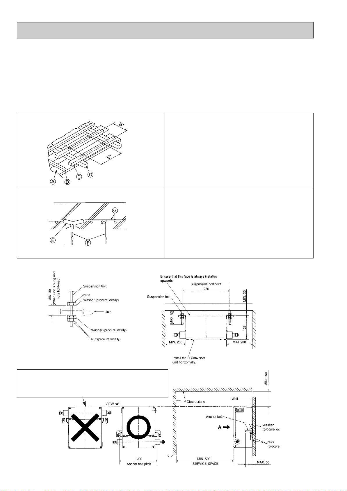
1-5. INSTALLATION
1-5-1. Installing the R-Converter Unit (mm)
Parts to procure locally
• Suspension bolts or anchor bolts : W3/8 (M10)
• Nut : W3/8 (M10)
• Washer : W3/8 (M10)
Installing the unit in a ceiling
(1) Install the suspension bolts
Wooden structures
• Use tie beams (single storied houses) or second floor
beams (two story houses) as reinforcing members.
• Wooden beams for suspending air conditioners must be
sturdy and their sides must be at least 6 cm long if the
beams are separated by not more than 90 cm. The size of
the suspension bolts should be M10 (W3/8). (The bolts are
not supplied with the unit.)
A Ceiling
B Rafter
C Beam
D Roof beam
B* Suspension bolt pitch
Ferro-concrete structures
Secure the suspension bolts using the method shown, or use
steel or wooden hangers, etc. to install the suspension bolts.
E Use inserts rated at 100-150 kg each (procure locally)
F Suspension bolts M10 (W3/8) (procure locally)
G Steel reinforcing rod
(2) Install the R-Converter unit.
Installing the unit on a wall
(1) Install the anchor bolts.
(2) Install the R-Converter unit.
Do not install the refrigerant pipes on top of the unit when
installing the unit on a wall, otherwise condensation can
enter the electrical devices, which can cause an electric
shock or a fire.
4
Page 5
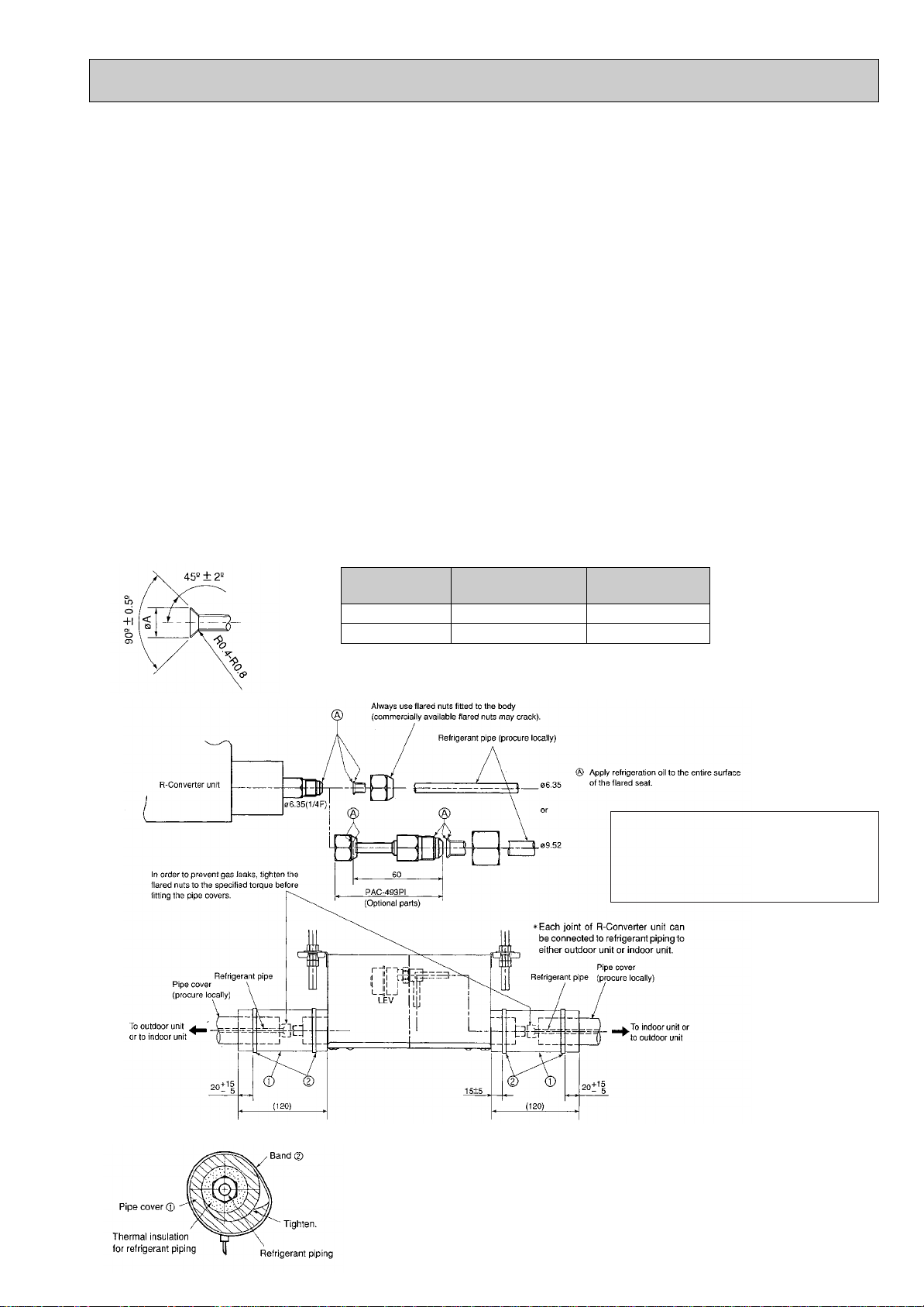
1-5-2. Installing Refrigerant Piping (mm)
Copper piping
O.D. (mm)
{6.35
{9.52
Flare dimensions
{A dimenson (mm)
8.6-9.0
12.6-13.0
Torque
N-m (kgf
•cm)
14-18 (140-180)
34-42 (340-420)
In order to prevent gas leaks, tighten the flared nut to the
specified torque even when not connecting the indoor unit
refrigerant piping.
Check the R-Converter unit accessories and parts
1 Pipe cover o 2 2 Band (long) o 4 3 Thermistor holder—[6.35 (liquid) o 1 4 Thermistor holder—[9.52 (liquid or gas) o 1
5 Thermistor holder—[12.7 (gas) o 1 6 Thermistor holder—[15.88 (gas) o 1 7 Thermistor insulation (3o150o60) o 2
8 Band (short) o 2
Connect R-Converter unit to the liquid pipe
• For identification purposes, list the indoor unit model names in the nameplate on the control box of the R-Converter
unit.
• To prevent water from dripping from the refrigerant piping, wrap both the liquid and gas piping with commercially available
thermal insulation that is at least 12 mm thick and which is able to withstand temperatures in excess of 100 °C.
• See the indoor and outdoor unit installation manual when creating a vacuum and opening or closing valves.
• Install the piping so that vibrations from the piping do not transmit to the unit.
Installing piping to the unit
(1) Remove the flared nuts and caps from the R-Converter unit.
(2) Flare the ends of the liquid and gas piping, and apply refrigeration oil (procure locally) to the flared seat.
(3) Connect the refrigerant piping immediately. Always tighten the flared nuts to the specified torque using a torque wrench and
double spanner.
(4) Press the pipe covers 1 on the liquid piping against the unit and wrap it to hold it in place.
(5) Fasten the supplied bands 2 10-20 mm from each end of the pipe covers 1 .
. Caution :
• Tighten the flare nut with a torque wrench in the specified method.
• Do not use the existing refrigerant piping, when use R407C refrigerant.
• Take precautions so that the Freon gas is not leaked during a fire.
Section of connection
Match the refrigerant piping size to
the indoor unit. If using a liquid pipe
that is [[9.52 mm, use joint pipe PAC493PI or a locally procured tandem
joint.
• Refrigerant charge :
See the outdoor unit installation manual.
Use only R407C or R22 refrigerant.
• Use the following procedures for connecting parts to
the indoor unit.
a) Tighten the flared nuts to prevent refrigerant leaks.
b) Fasten the pipe covers 1 to the pipes with the
bands 2 to prevent condensation.
5
Page 6
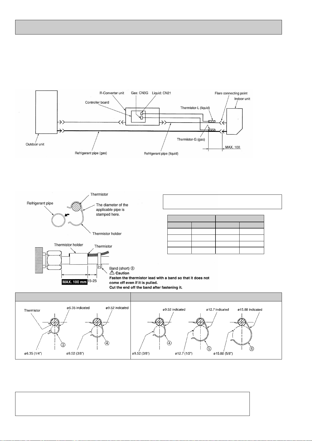
1-5-3. Installing the thermistors (mm)
Indoor unit capacity pipe size (mm)
BTU
07, 09
12, 13
18
24, 30
HP
1
1.6
2
2.5
Liquid
{6.35
{6.35
{6.35
{9.52
Gas
{9.52
{12.7
{15.88
{15.88
Be sure to install the thermistors (gas and liquid) supplied with the unit as shown in the illustration.
• If the thermistors are not installed, the unit will not operate. If the thermistors are installed incorrectly, the unit will not operate
properly.
Take precaution so that condensation does contact the thermistor leads or enters the electrical devices.
Before installing thermal insulation to the frame connecting points of the indoor unit, be sure to install the thermistors
according to the procedures given on this page.
Thermistor installation order
(1) Securely fasten the thermistors (liquid and gas) supplied with the unit using the thermistor holders (3, 4, 5, 6) at the
fastening points of indoor unit refrigerant pipes.
• Set thermistor-L (liquid) in thermistor holders 3 or 4 and thermistor-G (gas) in thermistor holders 4, 5 or 6, and then
fasten the refrigerant pipes.
Select thermistor holders that match the size of the
refrigerant piping.
Liquid
Gas
. Caution :
• To prevent condensation from dripping on the thermistor fasteners, wrap them with sufficient thermal insulation.
• Install the thermistors so that the piping is on top (as shown in above illustration).
• Take out the thermistor lead from above the piping.
• Install the thermistors indoors.
• Route the following lead, line, and cable pairs so that they do not come into contact with each other.
-Thermistor lead and indoor unit-R-Converter transmission line
-Thermistor lead and power supply cable
-Transmission line and power supply cable
6
Page 7
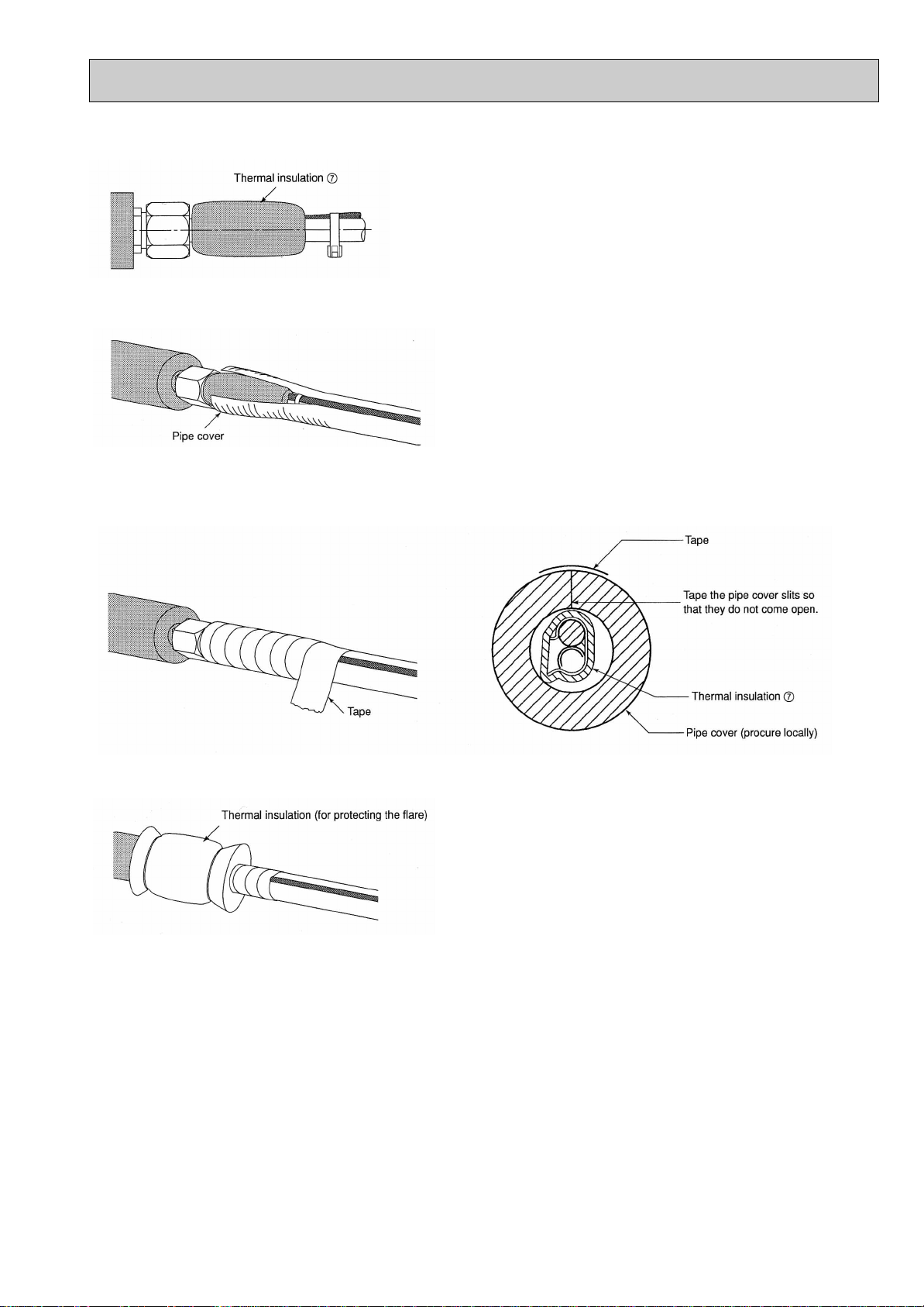
(2) Insulate the thermistors with the supplied thermal insulation 7.
(3) Cut a 100 mm slit on the top portion of the extension piping pipe covers, and then cover the thermistors with the pipe
covers.
(4) Wrap the thermal insulation covering the thermistor with tape.
. Caution :
Be sure to take out the thermistor lead from above.
(5) Cover the flare and thermistor with the thermal insulation (for protecting the flare) supplied with the indoor unit.
Bundle up the excess thermistor lead.
. Caution :
• Do not make the thermistor lead taut.
• Do not add extensions to the thermistor lead.
• Do not cut the excess thermistor lead.
• Make sure that the bundled thermistor lead does not interfere with any other wiring.
7
Page 8
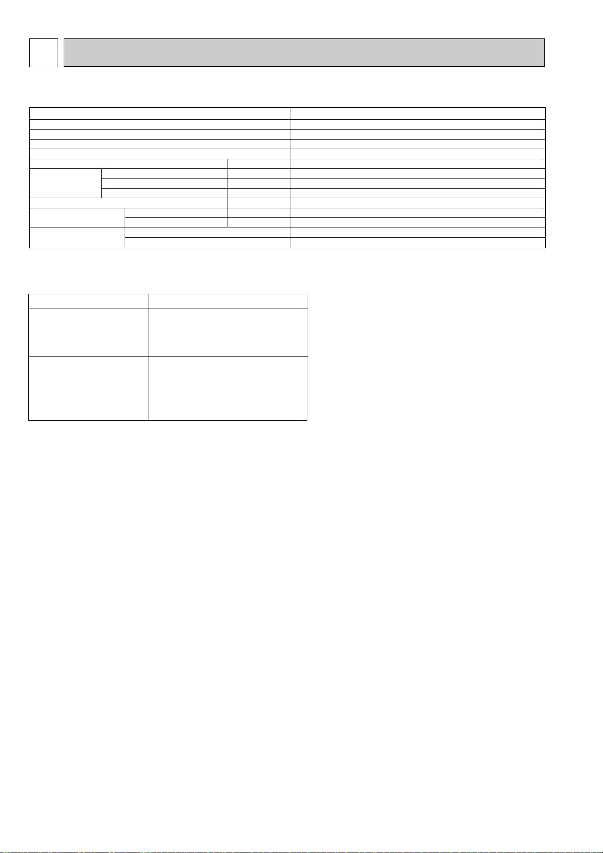
2 SPECIFICATIONS
mm
mm
mm
mm
kg
mm(in.)
mm(in.)
Model name
Connectable number of indoor units
Total capacity index of indoor units to be connected
Power supply
External finish
Drain hose size (on site)
Dimensions
Weight
Piping connection (Flare)
Wiring
Width
Depth
Height
Liquid
Gas
To indoor unit
To outdoor unit
PAC-SF29LB
1
Type 20-63
Single phase, 220/230/240V, 50Hz, Single phase, 220V, 60Hz
Hot-dip Zinc - coated steel (No external finish)
—
280
220
126
2.8
6.35 (1/4)W
—
2-core cable
2-core shield cable (Non-polarized)
Model Name (series)
Connectable indoor units
Connectable outdoor units
Wall mounted MS series*
Cassette Ceiling SL series*
PUMY series *
* See page 2 for detail model name.
R-Converter Unit : PAC-SF29LB
W If using on indoor unit with [9.52 piping connection and using a [9.52 refrigerant pipe, use joint pipe “PAC-493PI” (optional
parts) or a locally procured tandem joint ([6.35
➝[9.52)
8
Page 9

3 OUTLINES AND DIMENSIONS
MIN.150
MAX.50
Suspension bolt
MAX50
3
103
LEV
126
MIN.200
126 MIN.30
(220)
MIN.100
CEILING MOUNT
(280)
MAX.50
MIN.100
MIN.50
Obstructions
WALL MOUNT
450
Anchor bolt
MAINTENANCE HOLE
Suspension bolt
450
VIEW "A"
MAINTENANCE HOLE
"A"
MIN.500
SERVICE SPACE
Obstructions
<mm>
S=1:4
280
Wiring
Terminal block
Band
1/4F
110
40
Electric cover
12
GAS
CN3G
CN21
LIQUID
1/4F
24
8
18
Band
FUSE
26 40
85
3.15A 250V
Suspension bolt pitch
260
300
2✕2- [6 hole
Wiring
Wiring
50/60Hz
2
NL
Band
3N
SM1
M2
2-Electric wire inlet
/N 220-240V/220V
<POWER SUPPLY>
Terminal block:TB2
Controller board
DC12V
Terminal block:TB3
<TO INDOOR UNIT>
* V = 126H * 280W * 220D = 0.0078 m
* Weight : 2.8kg
* Suspension bolt or Anchor bolt : M10(W3/8)
DC24V-30V
Terminal block:TB5
<TO OUTDOOR UNIT>
9
Page 10

4 WIRING DIAGRAM
10
Page 11

5
Capillary tube
in R-Converter Unit
1 : {3.6 o {2.4 o L95
2 : {3.6 o {2.4 o L150
Liquid (mm)
Gas (mm)
{6.35w (IN/OUT)
Indoor unit capacity pipe size (mm)
BTU
07, 09
12, 13
18
24, 30
HP
1
1.6
2
2.5
Liquid
{6.35
{6.35
{6.35
{9.52
Gas
{9.52
{12.7
{15.88
{15.88
<Reference>
Conversion formula
1/4F
3/8F
1/2F
5/8F
3/4F
{6.35
{9.52
{12.7
{15.88
{19.05
Model name
Connected pipes diametermmDiameter AmmDiameter B
mm
{6.35 → {9.52 {6.35 {9.52PAC-493PI
Outdoor unit capacity pipe size (mm)
kcal/h
12500
kW
14.0
Liquid
{9.52
Gas
{19.05
TH23j
R-Converter Unit1
R-Converter Unit2
Indoor Unit2
Indoor Unit1
Outdoor Unit
Capillary tube
LEV1
HIC
TH1
TH5
TH6
Comp
Acc
SV
O/S
THHS
21S4
63HS
TH2
LEV2j
LEV2j
TH23j
HEX
HEX
HEX
TH22j
TH22j
Functioal Parts
<Outdoor Unit>
<R-Converter Unit>
Compressor
Oil Separator
High Pressure Sensor
4-way Valve
Heat Exchenger
Overcooling Heat Exchenger
Electronic Expansion Valve
Accumulator
Electronic Expansion Valve
Comp
O/S
63HS
21S4
HEX
HIC
LEV1
Acc
LEV2j
Thermistor
<Outdoor Unit>
<R-Converter Unit>
Discharge Temperature Sensor
Saturation Temperature of Suction Pressur
Piping Temperature
Outdoor Air Temperature
Liquid Pipe Temperature
Gas Pipe Temperature
TH1
TH2
TH5
TH6
Th22j
Th23j
NECESSARY CONDITIONS FOR SYSTEM CONSTRUCTION
5-1. REFRIGERANT SYSTEM DIAGRAM
• Piping connection size of R-Converter Unit
W If using a [9.52 refrigerant pipe, use joint pipe
“PAC-493PI” (optional parts) or a locally
procured tandem joint ([6.35➝[9.52)
• Piping connection size of indoor unit
Select piping that match the size of the Indoor Unit
piping connection.
• Piping connection size of outdoor unit
• Different-diameter joint (Optional parts)
11
Page 12

6 TROUBLESHOOTING
6-1. Test Run
. Caution :
Before operating the unit, check that the wiring, piping, and thermistors are installed and that the switches have been
set.
Refer to the "Test run" section of the indoor units and outdoor unit installation manuals.
After installation of an indoor unit, R-Converter unit, and outdoor unit, begin a test run to check water leaks in the R-Converter
unit.
Be sure to perform a test run in cooling mode for each indoor unit installed. Make sure that each indoor unit operates
properly following the installation manual supplied with the unit.
If a test run is performed on all indoor units at once, improper connection of the refrigerant pipes and the indoor and outdoor
unit connecting wires cannot be detected.
. Caution :
• Always use the remote controller to operate the indoor unit.
• When using an R-Converter unit, operation from the outdoor unit is not possible.
• The following symptoms are not malfunctions.
Symptom
Indoor unit does not operate
even if set to cooling (heating )
operation
Indoor unit fan stops during
heating operation
W See the operation manual of indoor units for details.
WW This mode is activated for approximately 1 minute to help avoid an insufficient supply of refrigerant during heating opera-
tion when refrigerant is stored in an indoor unit that has been turned off or thermo-off.
• A hissing noise can be heard immediately after the air conditioner is started or stopped. This is the sound of the refrigerant
flowing inside R-Converter unit. The problem is insignificant.
The cooling (heating) operation cannot be operated when the
cooling (heating) operation of another indoor unit is operating.
The fan stops during defrosting operation.
Fan stops when the refrigerant collecting mode WW is activated.
When this occurs, the vanes close.
Cause
Indoor unit LED display W
Stand by
(For Multi System)
—
Stand by
(For Multi System)
12
Page 13

6-2. Self-diagnosis and Remedy (Display on Outdoor controller board)
Error code Error codeTrouble Trouble
1102
1108
1302
1500
1501
1505
2502
2503
4115
4116
4220
4230
4250
5101
5102
5103
5105
5106
5110
Discharge temperature trouble
Compressor's inner thermal sensor trouble
High pressure trouble
Excessive refrigerant replenishment
Insufficient refrigerant
Vacuum operation protection
Drain pump trouble
Drain sensor trouble (THd)
Power synchronization signal trouble
Indoor unit fan rotation trouble
Inverter main voltage drop
Overheat protection of radiator panel
Multiple IPM errors
Intake thermistor trouble (TH21) or discharge
thermistor trouble (TH1)
Liquid pipe thermistor trouble (TH22) or intake pressure
saturation pressure thermistor trouble (TH2)
Gas pipe temperature sensor trouble (TH23)
Piping temperature sensor trouble (TH5)
Outdoor temperature sensor trouble (TH6)
IPM heat sink thermistor trouble (THHS)
Pressure sensor trouble (63HS)
Duplicated unit address setting
Transmission error (Transmission processor
hardware error)
Transmission error (Transmission route BUSY)
Transmission and reception error
(Communication trouble with transmission processor)
Transmission and reception error (No ACK error)
No response
MA communication receive signal error
(no receive signal)
MA communication send signal error
(starting bit detection error)
MA communication send error (H/W error)
MA communication receive error
(Synchronous recovery error)
total capacity error
Capacity code error
Connecting unit number error
Address set error
Remote controller sensor trouble
5201
6600
6602
6603
6606
6607
6608
6831
6832
6833
6834
7100
7101
7102
7105
7111
Display
7101
7103
1110
Meaning and detecting method Causes Check points
Capacity code error
1Abnormal if capacity code SW of R Converter unit is set to "0".
2Abnormal if capacity code setting
of R-Converter unit is not the same
as that of indoor unit.
1No setting or setting mistakes of
capacity code SW.
2Mis-wiring connection between
indoor unit and R-Converter unit
(Converse wiring).
1Check capacity code setting.
2Check if there is no mis-wiring
connection.
Combination error
1Abnormal if R-Converter unit is
connected to the indoor unit which
is not designed for connecting to R Converter type.
2Abnormal if system remote
controller (SC) remote controller is
connected to R-Converter unit.
1The indoor unit is not designed for
connecting to R-Converter unit.
2System remote controller (SC)
remote controller is connected to
R-Converter unit.
1Check if the model name of the
indoor unit is listed up on page 2.
2Check if system remote controller
(SC) remote controller is a part of
R-Converter
Converse connection error
1Abnormal if the equation below is
continuously detected for 10
minutes during cooling operation.
Intake temperature - piping
temperature (TH22 or TH23) [
3deg
2Abnormal if the equation below is
continuously detected for 10
minutes during cooling operation.
Indoor main pipe temperature -
gas pipe temperature (TH23) ]
25deg
1Converse connection of extension
pipe between indoor unit and R Converter unit
2Converse connection of
communication wire between
indoor unit and R-Converter unit.
3Disconnection of sensor,
No installation or installation
mistakes of sensor
4Shortage or leakage of refrigerant,
Clogged refrigerant circuit
1Check if the connection of
extension pipe is converse.
2Check if the communication wire is
converse.
3Check if sensor is correctly
installed.
4Check piping temperature by test
run.
<Abnormalities detected with the power on>
Error codes will be displayed in LD1 on the outdoor controller board if abnormalities occur while unit is running. Therefore,
check LD1 on the outdoor controller board first in that case. If no code is displayed in LD1, check LED on the indoor controller
board.
<List of error codes in LD1>
W Read the technical manual of outdoor unit if codes listed up above are displayed.
13
Page 14

Switch
SW1 1
2
3
4
5
6
7
8
SW2
SW4 1
2
3
4
5
6
SW11
SW12
Pole Function
Operation by Switch
When to set Remarks
ON OFF
Converse connection error (1110) detection
No Function
Correction of liquid pipe temperature in
heating operation
Change of LEV opening pulse
Change of Remote display
Humidifier control
Correction of liquid pipe temperature in
cooling operation (1)
Correction of liquid pipe temperature in
cooling operation (2)
No Function
No Function
No Function
Correction of LEV opening pulse in dry
operation
Solutions for refrigerant flowing sound after
defrosting operation
Solutions for refrigerant flowing sound
during defrosting operation
Capacity code setting
During stopping the
operation
Setting made at the factory
R-Converter unit controller board
Set the capacity setting of
the R-Converter unit equal
to the capacity setting of
the indoor unit.
Before turning the
power on
Before turning the
power on
Before turning the
power on
Inactive
Active
Change
On signal of thermostat
Always in heating
Active
Inactive
No change
Output from Fan
Thermo-on in heating
Active
Active
Active
Inactive
Inactive
Inactive
Capability
description
Btu HP
Capability
description
Btu HP
SW2 SW2
07
ON
OFF
-
1
1.6
15
2
2.5
-
17
18
24
30
08
09
10
12
13
1 23456
1 23456
1 23456
ON
OFF
ON
OFF
ON
OFF
1 23456
ON
OFF
1 23456
ON
OFF
1 2345678
1 23456
1 23456
ON
OFF
ON
OFF
Setting made at the factory
ON
OFF
1 23456
Setting made at the factory
Addresses setting on board
Setting made at the factory
6-3. Internal Switch Function Table
R-Converter Unit
(1) Before turning on the power of the indoor unit, be sure to set the SW2. If the switches are not set or if the setting are
incorrect, the device will not operate properly.
(2) After setting the switches, turn the indoor unit, R-Converter unit, and outdoor unit on in that order.
(3) In case capacity code setting or address setting is mistaken, reset it, turn off power supply of the outdoor unit, R-Converter
unit and indoor unit for 2 minutes or more at the same time and turn on power supply again in the order of (2).
14
Page 15

6-4. How to check the parts PAC-SF29LB
Parts name
Liquid pipe thermistor (TH22)
Gas pipe thermistor (TH23)
Disconnect the connector then measure the resistance using a tester.
(Surrounding temperature 10
°
C-30°C)
Check points
(Refer to the thermistor)
Normal
4.3k"-9.6k"
Abnormal
Open or short
<Thermistor Characteristic graph>
Thermistor for
lower temperature
Thermistor R0 = 15k" i 3%
B constant = 3480k" i 1%
0°C
10°C
20°C
25°C
Rt = 15exp {3480( )}
Liquid pipe thermistor (TH22)
Gas pipe temperature thermistor (TH23)
273+t 273
11
15k"
9.6k"
6.3k"
5.2k"
30°C
40°C
4.3k"
3.0k"
0
10
20
30
40
50
-20 -10 0 10 20 30 40 50
Temperature (:)
Resistance (K")
6-4-1. Thermistor
15
Page 16

6-4-2. Linear Expansion Valve
M
LEV
Blue
{4
{3
{2
{1
{4
{3
{2
{1
6
5
4
3
2
1
BRN
RED
BLU
ORN
YLW
WHT
Brown
Yellow
Red
White
Orange
1
5
2
3
6
4
Controller board
DC12V
Drive circuit
Connector (CN60)
A
E
D
C
B
Closing
Opening
Completely sealed (80-100 pulses)
Number of pulses
Valve fully open
at 2,000 pulses
Valve position (volume)
Parts name
Linear expansion valve
Disconnect the connector then measure the resistance valve using a tester.
Refer to the next page for a detail.
Check points
Normal
150k" i10%
Abnormal
Open or short
(1)-(5)
White-Red
(2)-(6)
Yellow-Brown
(3)-(5)
Orange-Red
(4)-(6)
Blue-Brown
Blue
1
2
4
1
5
3
2
6
4
3
5
6
Brown
Yellow
Orange
Red
White
M
Linear expansion valve
11
Operation summary of the linear expansion valve.
• Linear expansion valve open/close through stepping motor after receiving the pulse signal from the indoor controller board.
• Valve position can be changed in proportion to the number of pulse signal.
<Connection between the indoor controller board and the linear expansion valve.>
Note : Since the number of the connector at the controller board side and the relay connector are different, follow the color of
the lead wire.
22
Output pulse signal and valve action
Valve closing:1➔2➔3➔4➔1
Valve opening:4➔3➔2➔1➔4
The address of the pulse output is shifted using the procedures
mentioned earlier.
w1. All output phase will turn OFF when the LEV stops
operating.
2. When the output phase is terminated or when the phase
Output(phase)
{1
{2
{3
{4
(a) LEV action
1
ON
ON
OFF
OFF
Output
23
OFF
ON
ON
OFF
OFF
OFF
ON
ON
4
ON
OFF
OFF
ON
shift is not according to frequency, the motor rotation will
become irregular, causing the motor to vibrate or lockup.
w When the power supply is on, the closing signal of 2,200
pulse will be transmitted to decide the position of the valve.
The valve position can be determined when point A is
reached.
The LEV will not vibrate or make noise when the valve is
operating smoothly. However, when the number of pulses
change from E to A ,or if the valve lockup, there may be
more noise than under normal circumstances.
• The noise can be heard by resting your ear on the handle
of a screwdriver that is pressed against the top of the
LEV valve.
16
Page 17

3 Troubleshooting
Problem Check point Corrective measure
Remove the connector from the controller board and connect diagnostic
LEDs.
Pulses will be issued for 10 seconds when the power is turned on.
It indicates that there is an abnormality in the operating circuit if
any LEDs don't turn on or off.
If the linear expansion valve becomes locked and the motor is still operating,
the motor will emit a clicking noise and will not function. This clicking noise
indicates an abnormality.
Use an all-purpose electrical meter to measure the resistance between the
different coils (red-white, red-orange, brown-yellow, brown-blue). Normal
resistance is within a range of 150'±10%.
In order to check the linear expansion valve, operate one indoor unit in the
fan mode and another in the cooling mode. Then, use the outdoor multi
controller board to operate the monitor and check the pipe temperature of the
indoor unit (RT12). The linear expansion valve should be fully closed when
the fan is operating. The temperature measured by the temperature sensor
will drop if there is any leakage.
If the measured temperature is significantly lower than that on the remote
controller, this indicates that the valve is not closed. It is not necessary to
replace the linear expansion valve if the leak of refrigerant is small and does
not cause a malfunction.
1 Check improperly connected connector terminals and the wire colors.
2 Remove the connector on the controller board side and check electrical
conductance
Malfunction in
microprocessor
operating circuit
Locked expansion
valve
Short circuit or broken
circuit in expansion
valve motor coil
Valve does no close
completely
Incorrect connection
or connection failure
Replace the R-Converter
controller board
Replace the linear
expansion valve
Replace the linear
expansion valve
Replace the linear
expansion valve if there
is a major leak of
refrigerant.
Continuity check of
wrong part.
6
5
4
3
2
1
1k" LED
17
Page 18

6-5. Monitoring Function
Operating status
LED1
Green
LED2
Red
LED3
Red
When power supply is turned on.
Operating status of the indoor unit.
Error occurring on R-Converter Unit
When main supply for R-Converter unit is OFF.
(220V~240V 50Hz/220V 60Hz)
During start-up
Completion on start-up
During operation
Under suspension
Lighting
Lighting
Lighting
Lighting
—
OFF
Blinking
(ever 1.0 sec.)
OFF
Blinking
(ever 0.2 sec.)
Blinking
(ever 0.2 sec.)
—
—
OFF
OFF
Lighting
OFF
Blinking
—
Note LED2 blinks ever 0.2 secs, all the time once after the indoor unit is operated.
6-5-1. R-Converter Unit
18
Page 19

7 ELECTRICAL WORK
Model
Minimum wire thickness (mm
2
)
Breaker for wiring (NFB)
15A
Breaker for current leakage
15A
Branch GroundMain cable
1.5 1.51.5R-Converter unit
7-1. Caution
(1) Follow local regulations and ordinances for technical
standards related to electrical equipment, wiring, and
specifications of each electric power company.
(2) Wiring for control (hereinafter referred to as transmission
line) must be situated at least 5 cm from the power source
wiring so that it is not influenced by electrical noise. (Do not
insert transmission line and power source wire in the same
conduit.)
(3) Be sure to provide designated grounded work to outdoor
unit.
(4) Never connect the main power source to the terminal block
of a transmission line. If connected, electrical parts will be
burnt out.
(5) Use a 2-core shield cable for connecting a transmission line
to TB5 of the R-Converter unit. If transmission of different
systems are wired with the same multiplecore cable, which
can result in poor transmission and receipt and can cause
incorrect operation.
(6) The system will not operate if connected improperly.
TB2 : Terminal block for power supply
TB3 : Terminal block for transmission line to indoor unit
TB5 : Terminal block for transmission line to outdoor unit
(7) Before turning the indoor unit and the R-Converter unit
on, be sure to set the switches. (See page 14).
(8) To turn the power on, turn on the indoor unit,
R-Converter unit, then the outdoor unit, in that order.
(9) For identification purposes, list the indoor unit model names
in the nameplate on the control box of the R-Converter unit.
7-2. Connecting the R-Converter unit, indoor unit and outdoor unit transmission cables
• Connect the outdoor unit (TB3) to the R-Converter unit (TB5). (Non-polarized 2-wire) The "S" terminal on the R-Converter unit
(TB5) is a shielding wire connection. For connecting cable specifications, refer to the outdoor unit installation manual.
• Connect the indoor unit (TB) to the R-Converter unit (TB3). For connecting cable specifications, refer to the indoor unit
installation manual.
Permissible Length
1 "Indoor unit - R-Converter unit"
Maximum transmission cable length : r
2 "Outdoor unit - R-Converter unit" + "R-Converter unit - R-Converter unit"
Maximum transmission cable length : (L
1
and r2, r3[ 10 m (2-Core 1.0 mm2)
1
+ L2) or (L1 - L3 + L4) or (L2 + L3 + L4) [ 200 m
7-3. Wiring of main power supply and equipment capacity
Thickness of wire for main power supply and on/off capacities
1. Use separate power supplies for the outdoor unit and R-Converter unit.
2. Consider the ambient conditions (ambient temperature, direct sunlight, rain, etc.) when wiring and making connections.
3. The wire size is the minimum value for metal conduit wiring. The power cord size must be 1 rank thinker in consideration of
voltage drops.
Make sure that the power supply voltage does not drop more than 10%.
4. Select non-fuse breaker (NFB) or earth leakage breaker (NV).
(A means for the disconnection of the supply with an isolation switch, or similar device, in all active conductors shall be
incorporated in the fixed wiring.)
5. Power supply codes of appliance must not be lighter than design 245 IEC 53 or 227 IEC 53.
6. Aswitch with at least a 3 mm contact separation in each pole must be provided by the air conditioner installation.
Power cable size : more than 1.5 mm
2
.
19
Page 20

. Warning :
• Be sure to use the specified wires for connection so that no external force is imparted to the terminal connections.
If the wires are not securely connected, a fire can occur.
• Be sure to use the appropriate type of overcurrent protection switch. Note that generated overcurrent may include
some amount of direct current.
. Caution :
• Some installation sites may require a ground-fault interrupter. If a ground-fault interrupter is not installed, an electric
shock can occur.
• Use only a circuit breaker and fuse of he specified capacity. Using a fuse and copper wire with excessive capacity
can cause a malfunction or a fire.
When connected to a CITY MULTI indoor unit in a system
M-NET system remote controllers cannot be used to operate the indoor unit that is connected to the R-Converter.
(1) Example of setting an address automatically
A Outdoor unit
B R-Converter unit
C Indoor unit
D Remote controller
E CITY MULTI indoor unit
F Unit remote controller (MA)
G M-NET transmission cable
(3) Group setting including R-Converter units are not possible.
(2) Example of a group setting not including R-Converter units
A Outdoor unit
B R-Converter unit
C Indoor unit
D Remote controller
E CITY MULTI indoor unit
G M-NET transmission cable
H Network remote controller (NR)
(4) Connecting to a system remote controller is not possible.
A Outdoor unit
B R-Converter unit
C Indoor unit
D Remote controller
E CITY MULTI indoor unit
G M-NET transmission cable
H Network remote controller (NR)
A Outdoor unit
B R-Converter unit
C Indoor unit
D Remote controller
E CITY MULTI indoor unit
G M-NET transmission cable
H Network remote controller (NR)
I System remote controller (SC)
20
Page 21

7-4. Wiring (mm)
(1) Remove the electrical cover.
(2) Insert the wiring and each thermistor into the unit, and then fasten them with the bands on the inside of the unit.
(3) Connect each wire to the terminal block securely.
(4) Connect each thermistor to the controller board.
• Thermistor (liquid) ➝ CN21
• Thermistor (gas) ➝ CN3G
(5) After installing the unit, install the electric cover.
21
Page 22

8 REFRIGERANT PIPING
Indoor unit capacity
*R-Converter unit
Liquid pipe size (mm)
BTU
07
09
12, 13
18
24, 30
HP
-
1
1.6
2
2.5
{6.35 o 0.8
{9.52 o 0.8
{6.35 o 0.8
Indoor unit connection example
• Connect one R-Converter unit per indoor unit.
• Connect the R-Converter unit the liquid pipe.
• The thermistor-L (liquid) is installed close to the connecting
point of the extension piping (liquid) for the indoor unit.
• The thermistor-G (gas) is installed close to the connecting
point of the extension piping (gas) for the indoor unit.
Piping connection size
Refrigerant piping system
W For details, see PUMY series technical & service manual.
Install sections a, b, c, d and e as shown in the illustration to
the R-Converter unit.
W If using a liquid pipe that is [9.52 mm, use joint pipe
“PAC-493PI” (optional parts) or a locally procured tandem
joint ([6.35➝[9.52 mm)
Additional refrigerant quantity
• If necessary, add additional refrigerant to the unit by
following the calculation method given in the outdoor unit
(PUMY) manual.
• When calculating the refrigerant quantity, be sure to include
the R-Converter unit-to-indoor unit liquid pipe length.
• The installation condition for the R-Converter unit-to-indoor
unit are as shown in the illustration below.
• The refrigerant pipe length from the indoor unit to the
R-Converter unit must be less than 10 m and its height
difference less than 8 m.
• Install the R-Converter unit within an indoor-unit-to-indoorunit height difference of 12 m.
• Match the refrigerant piping size to the indoor unit.
22
Page 23

9 PARTS LIST
1
2
3
4
5
6
7
8
9
10
11
12
Part No. SpecificationNo.
Wiring
Diagram
Symbol
Recommended
Q,ty
Price
Unit
Amount
Part Name
Q,ty/set
PAC-SF29LB
Remarks
(Drawing No.)
LEV BOX
CONTROLLER BOARD
TERMINAL BLOCK
TH. HOLDER ASSY
THERMISTOR-L
THERMISTOR-G
CONT COVER
BOX COVER
LEV ASSY
TERMINAL BLOCK
TERMINAL BLOCK
FUSE
(M1, M2, S)
(Liquid)
(Gas)
(3, N)
(L, N, )
250V 3.15A
(RG02A916G05)
(RG02T534H04)
(RG02T533H04)
1
1
1
1
1
1
1
1
1
1
1
1
R.C
TB5
TH22
TH23
LEV
TB3
TB2
FUSE
T7W E17 315
T7W E00 716
T7W E00 241
T7W E34 202
T7W E35 202
T7W E12 401
T7W E20 716
T7W 509 716
T7W E04 239
PAC-SF29LB
1
2
12
11
3
10
9
4
5
6
8
7
23
Page 24

HEAD OFFICE : MITSUBISHI DENKI BLDG., 2-2-3, MARUNOUCHI, CHIYODA-KU, TOKYO100-8310, JAPAN
cCopyright 2003 MITSUBISHI ELECTRIC ENGINEERING CO., LTD.
Distributed in Jun. 2003 No.OC296 PDF
Made in Japan.
New publication, effective Jun. 2003
Specifications subject to change without notice.
 Loading...