

Page 1
OUTLANDER PHEV - ENGLISH - OGGE16E1
OUTLANDER PHEV
OWNER’S MANUAL
OUTLANDER PHEV - ENGLISH - OGGE16E1
Page 2
Foreword
E09200106429
Thank you for selecting an OUTLANDER PHEV as your new vehicle.
This owner’s manual will add to your understanding and full enjoyment of
the many fine features of this vehicle.
It contains information prepared to acquaint you with the proper way to operate and maintain your vehicle for the utmost in driving pleasure.
MITSUBISHI MOTORS Europe B.V. reserves the right to make changes in
design and specifications and/or to make additions to or improvements in
this product without obligation to install them on products previously manufactured.
It is an absolute requirement for the driver to strictly observe all laws and
regulations concerning vehicles.
This owner’s manual has been written in compliance with such laws and regulations, but some of the contents may become contradictory with later
amendment of the laws and regulations.
Please leave this owner’s manual in this vehicle at time of resale. The next
owner will appreciate having access to the information contained in this
owner’s manual.
Repairs to your vehicle:
Vehicles in the warranty period:
All warranty repairs must be carried out by a MITSUBISHI MOTORS Authorized Service Point.
Vehicles outside the warranty period:
Where the vehicle is repaired is at the discretion of the owner.
Throughout this owner’s manual the words WARNING and CAUTION
appear.
These serve as reminders to be especially careful. Failure to follow instructions could result in personal injury or damage to your vehicle.
WARNING
indicates a strong possibility of severe personal injury or death if instructions are not followed.
CAUTION
means hazards or unsafe practices that could cause minor personal injury or damage to your vehicle.
You will see another important symbol:
NOTE: gives helpful information.
*: indicates optional equipment.
It may differ according to the sales classification; refer
to the sales catalogue.
Abbreviations used in this owner’s manual:
LHD: Left-Hand Drive
RHD: Right-Hand Drive
Information for station service
Fuel tank capacity 45 litres
Except for vehicles for Russia
Fuel
Engine oil Refer to the “Maintenance” section for the selection of engine oil.
Tyre inflation pressure Refer to the “Maintenance” section for the tyre inflation pressure.
Fuel requirements
Unleaded petrol octane number (EN228)
95 RON or higher
Except for vehicles for Russia
Unleaded petrol octane number (EN228)
98 RON or higher
E09300104208
© 2015 Mitsubishi Motors Corporation
OGGE16E1
BLO-15-000771
16
Page 3

Table of contents
Overview
General information
Charging
Locking and unlocking
Seats and seat belts
Instruments and controls
Starting and driving
For pleasant driving
For emergencies
Vehicle care
Maintenance
Specifications
Alphabetical index
Declaration of Conformity
1
2
3
4
5
6
7
8
9
10
11
12
13
14
OGGE16E1
Page 4
Instruments and controls
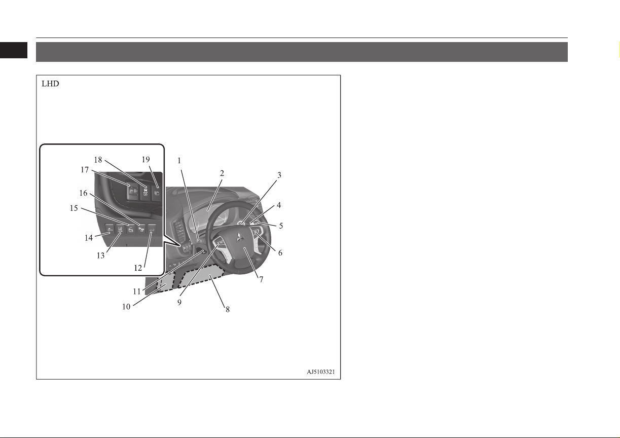
1
Instruments and controls
E00100108748
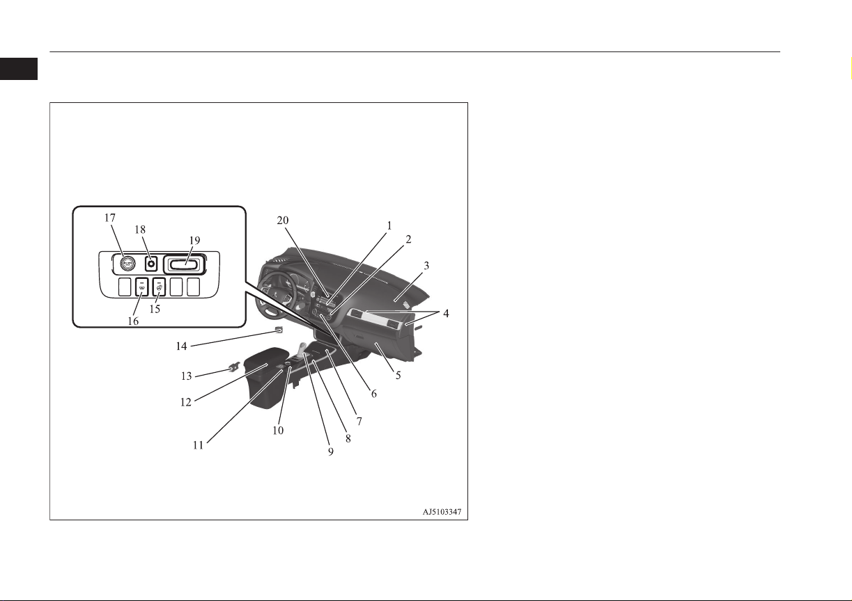
1. Combination headlamps and dipper switch p. 6-47
Turn-signal lever p. 6-52
Front fog lamp switch p. 6-54
Rear fog lamp switch p. 6-54
Headlamp washer switch p. 6-60
2. Instruments p. 6-02
3. Power switch* p. 7-09
4. Regenerative braking level selector (paddle) p. 7-16
5. Windscreen wiper and washer switch p. 6-55
Rear window wiper and washer switch p. 6-59
6. Cruise control switch* p. 7-34
Adaptive Cruise Control System (ACC)* p. 7-48
7. Supplemental restraint system - airbag (for driver’s seat) p. 5-29,
5-32
Horn switch p. 6-63
8. Supplemental restraint system (SRS) - front knee airbag (for driver’s seat) p. 5-33
9. Steering wheel audio remote control switches* p. 8-26
10. Fuse box p. 11-16
11. Steering wheel height and reach adjustment lever p. 7-05
12. Driver’s side electric tailgate switch* p. 4-20
13. Lane depature warning (LDW) switch* p. 7-69
14. Forward collision mitigation system (FCM) ON/OFF switch*
p. 7-60
15. Sonar switch* p. 7-79
16. Acoustic Vehicle Alerting System (AVAS) OFF switch p. 7-24
17. Headlamp levelling switch* p. 6-51
18. Active stability control (ASC) OFF switch* p. 7-33
19. Multi information display switch* p. 6-05
1-02
Overview
OGGE16E1
Page 5
Instruments and controls
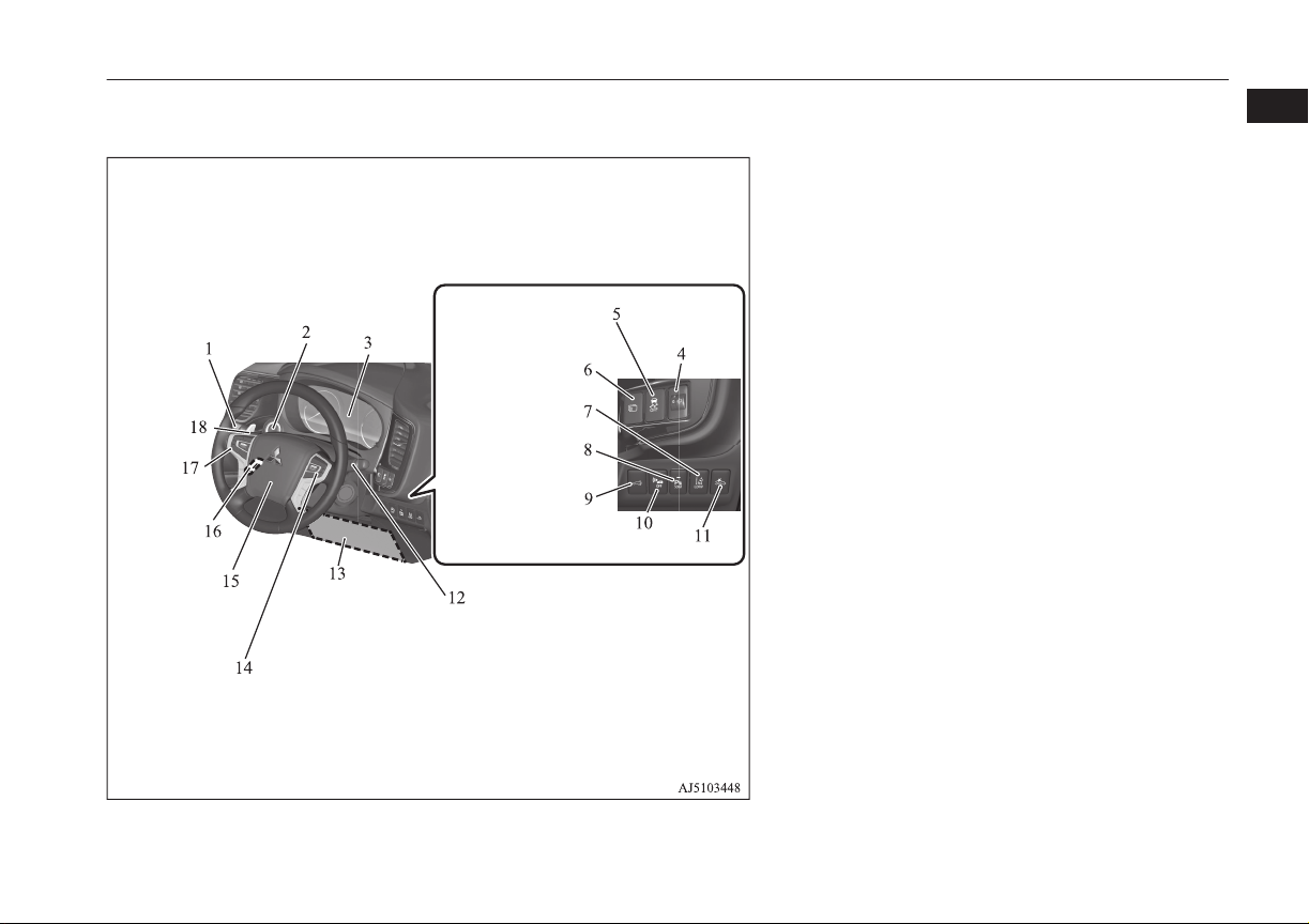
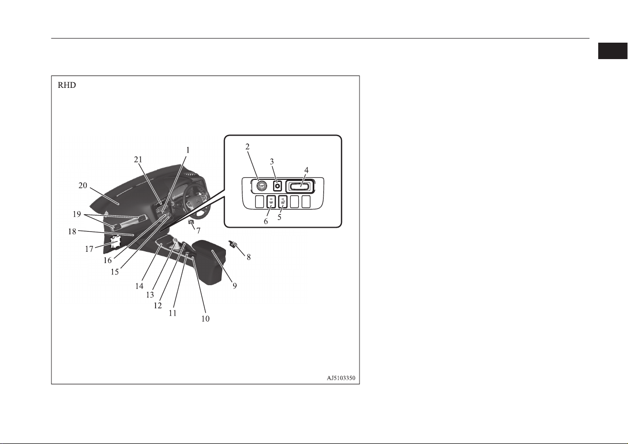
1. Combination headlamps and dipper switch p. 6-47
Turn-signal lever p. 6-52
Front fog lamp switch p. 6-54
Rear fog lamp switch p. 6-54
Headlamp washer switch p. 6-60
2. Power switch p. 7-09
3. Instruments p. 6-02
4. Headlamp levelling switch* p. 6-51
5. Active stability control (ASC) OFF switch* p. 7-33
6. Multi information display switch* p. 6-05
7. Lane Departure Warning (LDW) switch* p. 7-69
8. Sonar switch* p. 7-79
9. Driver’s side electric tailgate switch* p. 4-20
10. Acoustic Vehicle Alerting System (AVAS) OFF switch p. 7-24
11. Forward Collision Mitigation System (FCM) ON/OFF switch*
p. 7-60
12. Windscreen wiper and washer switch p. 6-55
Rear window wiper and washer switch p. 6-59
13. Supplemental restraint system (SRS) - front knee airbag (for driver’s seat) p. 5-33
14. Cruise control switch* p. 7-34
Adaptive Cruise Control System (ACC)* p. 7-48
15. Supplemental restraint system - airbag (for driver’s seat) p. 5-29,
5-32
Horn switch p. 6-63
16. Steering wheel height and reach adjustment lever p. 7-05
17. Steering wheel audio remote control switches* p. 8-26
18. Regenerative braking level selector (paddle) p. 7-16
1
OGGE16E1
Overview
1-03
Page 6
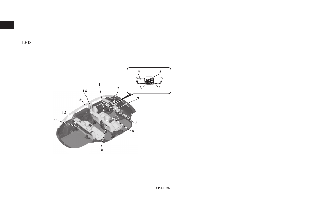
LHD
Instruments and controls
1
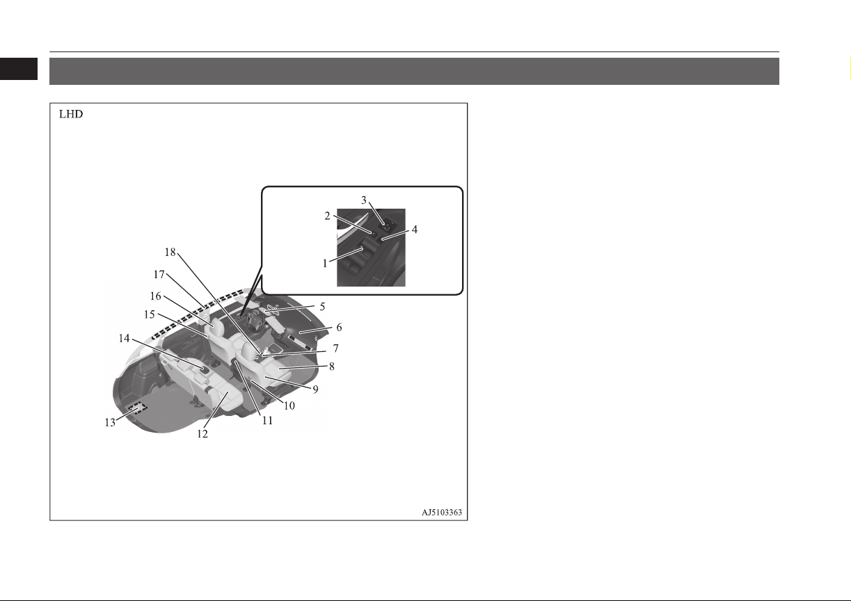
1. Hazard warning flasher switch p. 6-52
2. Air conditioner p. 8-04
3. Supplemental restraint system (SRS) - airbag (for front passenger’s seat) p. 5-29
4. Passenger’s ventilators p. 8-02
5. Glove box p. 8-78
Card holder p. 8-78
6. Rear window demister switch p. 6-61
Wiper de-icer switch* p. 6-60
7. Cup holder p. 8-80
8. Parking brake lever p. 7-03
9. Selector Lever (Joystick Type) p. 7-13
10. 4WD lock switch p. 7-18
11. Heated seat switch* p. 5-04
12. Floor console box p. 8-78
Armrest p. 5-03
Accessory socket p. 8-75
USB input terminal p. 8-70
13. Fuel tank filler door release lever p. 2-13
14. Bonnet release lever p. 11-04
15. Heated steering wheel switch* p. 6-62
16. Heated windscreen switch* p. 6-62
17. Accessory socket* p. 8-75
Cigarette lighter* p. 8-74
18. Electric tailgate power switch* p. 4-20
19. Key slot* p. 7-12
20. LW/MW/FM radio/CD player* p. 8-14
MITSUBISHI Multi Communication System (MMCS)*
[For DISPLAY AUDIO and MMCS, refer to the separate owner’s
manuals.]
Digital clock*
1-04
Overview
OGGE16E1
Page 7
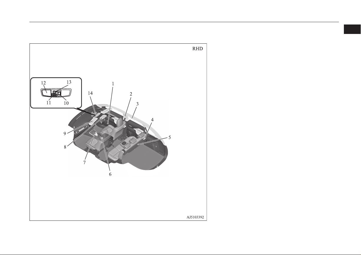
Instruments and controls
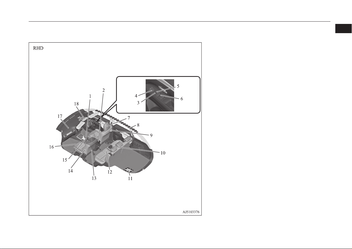
1. Hazard warning flasher switch p. 6-52
2. Accessory socket* p. 8-75
3. Electric tailgate power switch* p. 4-20
4. Key slot* p. 7-12
5. Heated steering wheel switch* p. 6-62
6. Heated windscreen switch* p. 6-62
7. Bonnet release lever p. 11-04
8. Fuel tank filler door release lever p. 2-13
9. Floor console box p. 8-78
Armrest p. 5-03
Accessory socket p. 8-75
USB input terminal p. 8-70
10. Heated seat switch* p. 5-04
11. 4WD lock switch p. 7-18
12. Parking brake lever p. 7-03
13. Selector Lever (Joystick Type) p. 7-13
14. Cup holder p. 8-80
15. Rear window demister switch p. 6-61
Wiper de-icer switch* p. 6-60
16. Air conditioner p. 8-04
17. Fuse box p. 11-16
18. Glove box p. 8-78
Card holder p. 8-78
19. Passenger’s ventilators p. 8-02
20. Supplemental restraint system (SRS) - airbag (for front passenger’s seat) p. 5-29
21. LW/MW/FM radio/CD player* p. 8-14
MITSUBISHI Multi Communication System (MMCS)*
[For DISPLAY AUDIO and MMCS, refer to the separate owner’s
manuals.]
Digital clock*
1
OGGE16E1
Overview
1-05
Page 8
1
Interior
Interior
E00100206439
1. Electric window control switch p. 4-34
2. Lock switch p. 4-35
3. Electric remote-controlled outside rear-view mirrors switch
p. 7-07
4. Central door lock switch p. 4-16
5. Sunroof switch* p. 4-36
Map & room lamps (front) p. 8-76, 8-77
Downlight p. 8-76
Hands-free microphone p. 8-51
6. Supplemental restraint system (SRS) - airbag (for front passenger’s seat) p. 5-29
7. Battery save switch p. 7-21
8. Front seat p. 5-03
Heated seats* p. 5-04
9. Supplemental restraint system (SRS) - side airbag (for front seat)*
p. 5-35
10. Tether anchorages for child restraint system p. 5-26
11. Floor console box p. 8-78
Armrest p. 5-05
Accessory socket p. 8-75
USB input terminal p. 8-70
12. Rear seats p. 5-05
13. Auxiliary battery p. 11-09
14. Armrest p. 5-05
Cup holder p. 8-80
15. Room lamp (rear) p. 8-76
16. Head restraints p. 5-05
17. Supplemental restraint system - curtain airbag p. 5-36
18. Battery charge switch p. 7-22
1-06
Overview
OGGE16E1
Page 9
Interior
1. Battery charge switch p. 7-22
2. Floor console box p. 8-78
Armrest p. 5-05
Accessory socket p. 8-75
USB input terminal* p. 8-70
3. Lock switch p. 4-35
4. Electric remote-controlled outside rear-view mirrors switch
p. 7-07
5. Central door lock switch p. 4-16
6. Electric window control switch p. 4-34
7. Head restraints p. 5-05
8. Supplemental restraint system - curtain airbag p. 5-36
9. Room lamp (rear) p. 8-76
10. Armrest* p. 5-05
Cupholder* p. 8-80
11. Auxiliary battery p. 11-09
12. Rear seats p. 5-05
13. Tether anchorages for child restraint system p. 5-26
14. Supplemental restraint system (SRS) - side airbag (for front seat)*
p. 5-35
15. Battery charge switch p. 7-22
16. Front seat p. 5-03
Heated seats* p. 5-04
17. Supplemental restraint system (SRS) - airbag (for front passenger’s seat) p. 5-29, 5-32
18. Sunroof switch* p. 4-36
Map & room lamps (front) p. 8-76, 8-77
Downlight p. 8-76
Hands-free microphone p. 8-51
1
OGGE16E1
Overview
1-07
Page 10
Interior
1
1. Bottle holder p. 8-81
2. Inside rear-view mirror p. 7-05
3. Hands-free microphone* p. 8-51
4. Map & room lamps (front) p. 8-76, 11-24
5. Downlight p. 8-76
6. Sunroof switch* p. 4-36
7. Sun visors p. 8-73
Vanity mirror p. 8-73
Card holder p. 8-73
8. Sunglasses holder* p. 8-80
9. Electrical Parking switch p. 7-15
10. Heated seats switch* p. 5-04
11. Cargo area cover p. 8-81
12. Luggage room lamp p. 8-77
13. Assist grips p. 8-82
Coat hook p. 8-83
14. Adjustable seat belt anchor p. 5-12
Seat belts p. 5-09
1-08
Overview
OGGE16E1
Page 11
1. Bottle holder p. 8-81
2. Adjustable seat belt anchor p. 5-12
Seat belts p. 5-09
3. Assist grips p. 8-82
Coat hook p. 8-83
4. Luggage room lamp p. 8-77
5. Cargo area cover p. 8-81
6. Heated seats switch* p. 5-04
7. Electrical Parking switch p. 7-15
8. Sunglasses holder* p. 8-80
9. Sun visors p. 8-73
Vanity mirror p. 8-73
Card holder p. 8-73
10. Sunroof switch* p. 4-36
11. Hands-free microphone* p. 8-51
12. Map & room lamps (front) p. 8-76, 11-24
13. Downlight p. 8-76
14. Inside rear-view mirror p. 7-05
Interior
1
OGGE16E1
Overview
1-09
Page 12
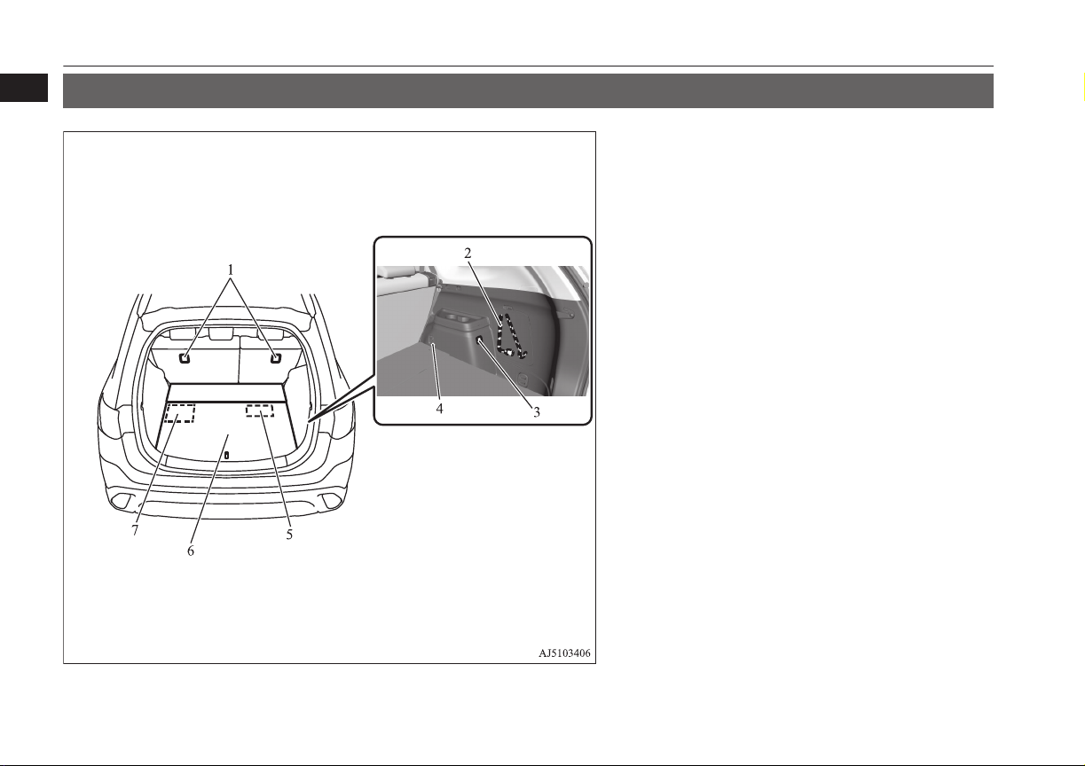
Luggage area
1
Luggage area
E00100402909
1. Tether anchorages for child restraint system p. 5-26
2. Tools p. 9-06
3. Accessory socket p. 8-75
4. Luggage hook p. 8-83
5. Jack p. 9-06
6. Luggage floor box p. 8-79
7. Tyre repair kit p. 9-07
1-10
Overview
OGGE16E1
Page 13
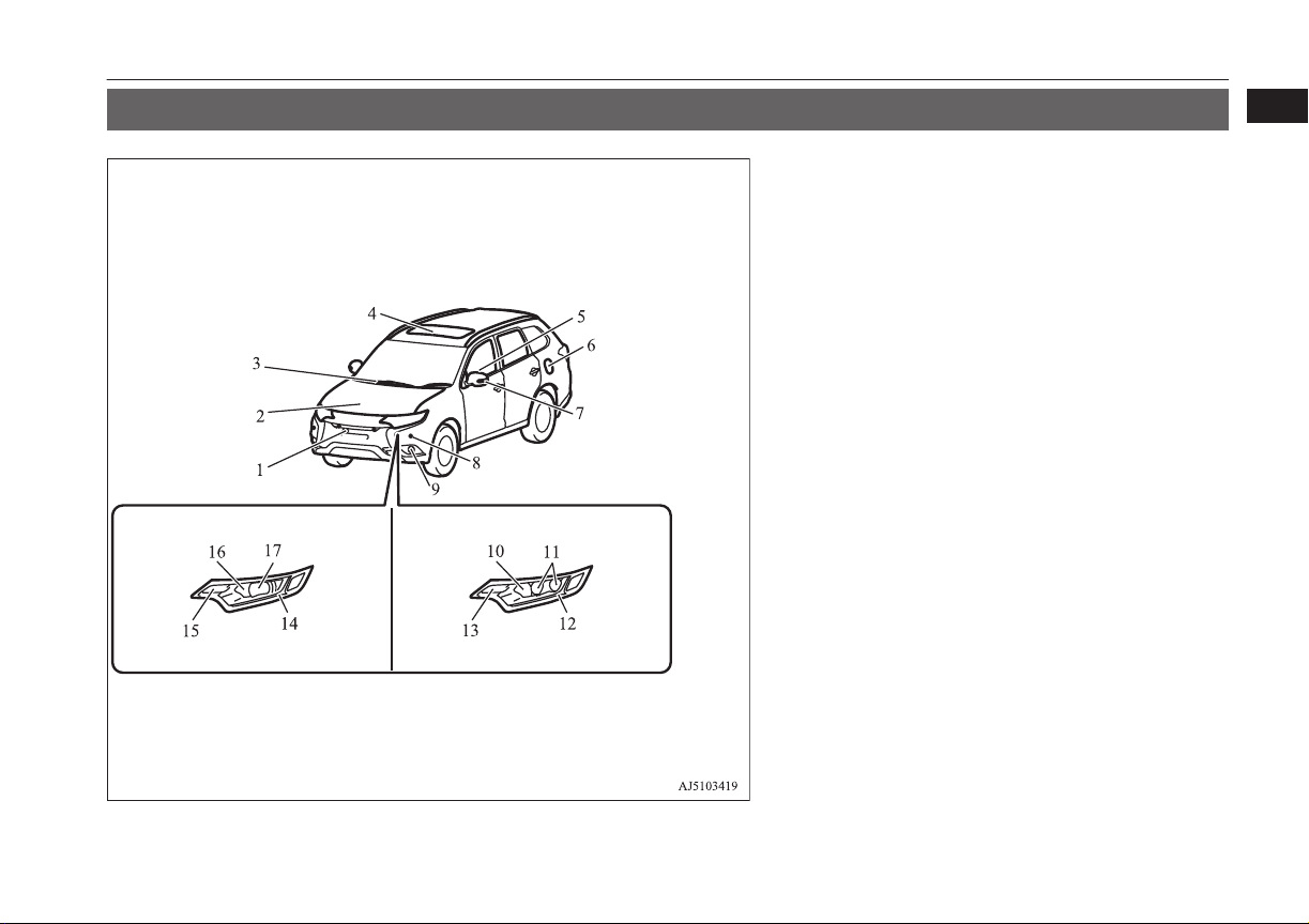
Halogen headlamps type LED headlamps type
Outside (Front)
Outside (Front)
1
E00100507338
1. Multi Around Monitor* p. 7-88
Front view camera* p. 7-88
2. Bonnet p. 11-04
3. Windscreen wipers p. 6-55
4. Sunroof* p. 4-36
5. Electric window control p. 4-34
6. Fuel tank filler p. 2-13
7. Side turn-signal lamps p. 6-52, 11-23, 11-26
Multi Around Monitor* p. 7-88
Side view camera* p. 7-88
8. Sensor system* p. 7-81
9. Front fog lamps p. 6-54, 11-23, 11-27
10. Headlamps, high-beam p. 6-49, 11-23, 11-25
11. Headlamps, low beam p. 6-49, 11-23, 11-24
12. Position lamps p. 6-47, 11-27
Daytime running lamps p. 11-27
13. Front turn-signal lamps p. 6-52, 11-23, 11-26
14. Position lamps p. 6-47, 11-27
Daytime running lamps p. 11-27
15. Front turn-signal lamps p. 6-52, 11-23, 11-26
16. Headlamps, high-beam p. 6-49, 11-23, 11-25
17. Headlamps, low beam p. 6-49, 11-23, 11-24
OGGE16E1
Overview
1-11
Page 14
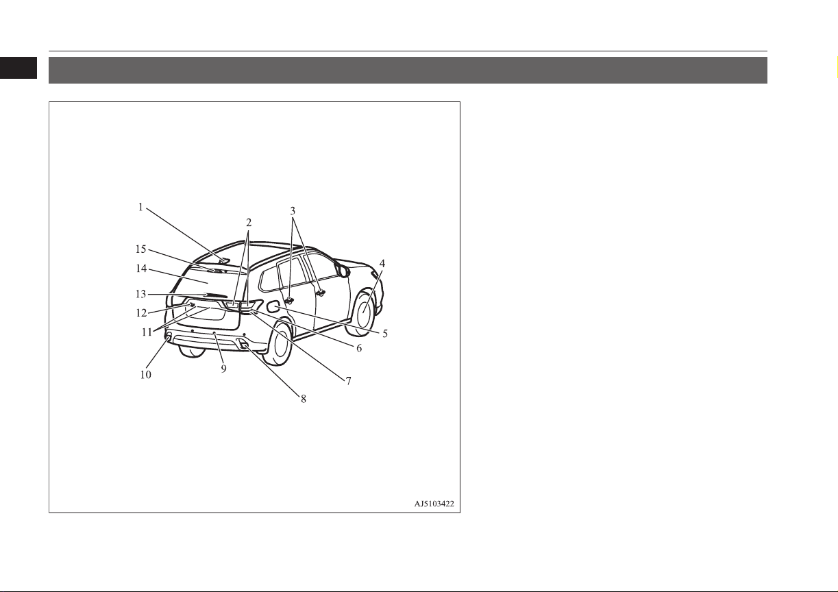
Outside (Rear)
1
Outside (Rear)
E00100507341
1. Antenna
2. Bulb location and capacity p. 11-23, 11-28
3. Keyless entry system* p. 4-03
Keyless operation system* p. 4-06
Locking and unlocking the doors p. 4-14
4. Changing tyres p. 9-13
Tyre pressure monitoring system (TPMS) p. 7-72
Tyre inflation pressures p. 11-10
Tyre rotation p. 11-11
Tyre chains p. 11-13
Size of tyres and wheels p. 12-08
5. Charging lid p. 3-12
Charging port courtesy lamp p. 3-06
6. Stop lamps/Tail lamps p. 11-23, 11-28
7. Turn-signal lamps p. 6-52, 11-23, 11-28
8. Reversing lamps (passenger’s side) p. 11-23, 11-23
9. Reversing sensor system* p. 7-77
Sensor system* p. 7-81
10. Rear fog lamp (driver’s side) p. 11-28, Reversing lamps (passenger’s side) p. 11-23
11. Licence plate lamps p. 11-23, 11-29
12. Rear-view camera* p. 7-84
Multi Around Monitor* p. 7-88
13. Rear window wiper p. 6-59
14. Tailgate p. 4-18
Electric tailgate p. 4-20
15. High-mounted stop lamp p. 11-23
1-12
Overview
OGGE16E1
Page 15

General information
Plug-in Hybrid EV System................................................................. 2-02
Drive battery....................................................................................... 2-04
EV cruising range................................................................................2-05
Acoustic Vehicle Alerting System (AVAS)....................................... 2-05
Operation sound setting...................................................................... 2-05
In case of a collision............................................................................2-05
Inspection and maintenance................................................................2-07
For persons with electro-medical apparatus such as im-
plantable cardiac pacemaker or implantable cardiovert-
er-defibrillator.................................................................................2-09
Cautions and actions to deal with intense heat................................... 2-10
Cautions and actions to deal with intense cold................................... 2-10
Fuel selection...................................................................................... 2-13
Filling the fuel tank.............................................................................2-13
Installation of accessories................................................................... 2-15
Modification/alterations to the electrical or fuel systems................... 2-16
Genuine parts...................................................................................... 2-16
Safety and disposal information for used engine oil...........................2-16
Disposal information for used batteries.............................................. 2-17
2
OGGE16E1
Page 16

Plug-in Hybrid EV System
Plug-in Hybrid EV System
2
Main features
It is operated as an electric vehicle in the EV
drive mode using the electrical power stored
in the drive battery,*1 according to the remaining amount of the drive battery. It is also
automatic control*2 for driving in series hybrid mode or parallel hybrid mode using engine power from EV drive mode according to
the driving condition or if the charging level
of the drive battery is decreased.
With the high performance motor, noise
l
and vibration during driving is minimized and powerful acceleration can also be obtained.
With the regenerative brake, the drive
l
battery is automatically charged when
the accelerator is released.
*1
If there is a remaining amount in the drive
battery, it is actively driven in the EV
drive mode. The cruising range varies depending on the remaining charge in the
drive battery, vehicle speed, and air conditioner operating conditions.
*2
You can adjust the timing to switch to the
EV drive mode by using the battery save
switch. Refer to “Battery save switch” on
page 7-21.
2-02
General information
E00203500041
E00203600101
The vehicle can be charged from EV
l
charge power outlets (rated AC
220-240 V).
Quick charging using CHAdeMO quick
l
charger (if so equipped) is available.
CHAdeMO is a quick charging standard
for electric vehicles that is promoted by
Japan for adoption as an international
standard.
EV drive mode
The vehicle is driven by the motors us-
l
ing only electrical power stored in the
drive battery. However, EV drive mode
is cancelled depending on the drive battery level, vehicle speed, and air conditioner operating conditions. Pay attention to the following points:
• Check the EV cruising range in the information screen. Refer to “EV cruising range display/Total cruising range
display” on page 6-14.
• Drive your vehicle at moderate speeds
avoiding quick acceleration/deceleration. Repeated quick acceleration/
deceleration causes the drive battery
level to decrease quickly, which extremely reduces the EV cruising
range.
OGGE16E1
Series hybrid mode
The vehicle is driven by the motors us-
l
ing only the electricity generated by the
engine. This mode is used when the
drive battery level is low, at quick acceleration, or when power is required like
climbing uphill.
Parallel hybrid mode
The vehicle is driven by the power of the
l
engine, assisted by motors. This mode is
used during high-speed driving with better engine efficiency.
The roles of the motors and engine in each drive mode
Driving
Motor Engine
EV Drive
Mode
Series
Hybrid
Mode
ON OFF
ON
Generates
electricity
condi-
tions
Driving
on streets
and com-
muting
Powerful
accelera-
tion uphill such
as moun-
tain road
Page 17
Plug-in Hybrid EV System
Driving
Motor Engine
condi-
tions
Drivers
Parallel
Hybrid
Mode
ON
front
wheels
and gen-
erates
Highspeed
driving
electricity
Regenerative braking
Motion energy is converted into electric energy using the motor as a power generator.
Then a braking force generates and converted
electric energy will be charged to the drive
battery.
If you lift your foot off the accelerator
l
pedal during driving, a braking force that
is equivalent to engine braking of a combustion engine vehicle will be generated.
Also, if you shift the select position into
“B” (BRAKE) from “D” (DRIVE), effectiveness of the regenerative braking is
getting stronger. Shift the selector lever
into “B” (BRAKE) position according to
the driving condition.
When you depress the brake pedal, the
l
regenerative braking force may be increased.
If a problem occurs in the Plug-in hybrid
l
EV system, or if the ABS and/or the
ASC have been activated, the regenerative braking will be restricted. The foot
brake will still operate.
Operation of gasoline engine
Even when the vehicle is driving in EV
l
drive mode, it may be automatically
changed to series hybrid mode or parallel hybrid mode in the following cases:
• The plug-in hybrid EV system is too
hot or too cold.
• Quick acceleration is applied.
• The air conditioner is operating.
• The accelerator pedal is depressed
hard on an uphill road or expressway.
• In cold weather.
• The vehicle has not been refueled for
a long time.
• The drive battery level is low.
In addition to the above, there are more
cases where EV drive mode is automatically changed to series or parallel hybrid
mode.
Even while the vehicle is stopped, the
l
engine may automatically be started in
the following cases:
• The drive battery level is low.
• The plug-in hybrid EV system is too
hot or too cold.
E00203700072
• The air conditioner is used.
• The vehicle has not been used for a
long time.
• The engine has not been operated for a
long time.
• The vehicle has not been refueled for
a long time.
Refueling (gasoline)
CAUTION
If the warning display appears, refuel imme-
l
diately.
If the vehicle runs out of fuel, the engine
will not start even in a situation need to be
generated electricity, the following conditions will occur.
The driving performance falls (since only
•
the electrical power stored in the drive
battery can be used for the driving).
The heating performance is not available
•
(except vehicles with electric heater).
The effectiveness of the heater is insuffi-
•
cient (vehicles with electric heater).
The catalytic converter may be damaged
•
due to excessive high temperature.
Refer to “Filling the fuel tank” on page
2-13.
Refer to “Fuel remaining display screen” on
page 6-10.
2
E00203800031
OGGE16E1
General information
2-03
Page 18
Drive battery
2
sumed and it may stagnate for a long time
depending on the use situation of the vehicle, the quality of fuel may change, and it
may have a bad influence on the engine or
the parts of a fuel system.
Observe the following instructions for prevention.
The fuel in the fuel tank may not be con-
l
Drive battery
A sealed lithium ion high voltage battery
l
(drive battery) is adopted for Outlander
PHEV. If the drive battery is disposed of
improperly, there is a risk of severe burns
and electrical shock that may result in serious injury or death and there is also a
risk of environmental damage.
Never attempt to use the drive battery for
l
any other purpose.
CAUTION
Press the battery charge switch to start the
•
engine within three months at once.
Refer to “Battery charge switch” on page
7-22.
Refill the fuel more than 15 litres at once
•
within three months. If the fuel remaining
display will be below half, you can refill
the fuel more than 15 litres certainly.
Refer to “Fuel remaining warning display” on page 6-11.
E00205000024
WARNING
It is the battery to operate the motor and
l
the air conditioning.
In addition to the drive battery, Outlander PHEV has the auxiliary battery to operate lamps, wipers, etc.
Compact, light-weight lithium ion bat-
l
tery with high energy density is used for
the drive battery.
The drive battery has the following char-
l
acteristics.
Please read this carefully paying attention to the following:
Characteristics
The same as ordinary lithium-ion batter-
l
ies, the battery capacity of the drive battery gradually reduces with time, resulting in reduced cruising range. Depending on the usage conditions, such as frequent quick acceleration/deceleration,
extremely hot weather, storing the vehicle in high ambient temperatures, etc.,
the rate of battery capacity drop will increase.
The performance may be changed due to
l
the outside temperature.
At low temperature, in particular, the EV
cruising range is short and the charging
time is long, compared to operation at
normal temperature.
The battery is gradually discharged with-
l
out use and the battery charge is lowered.
It is not necessary to consume the bat-
l
tery completely before charging.
Precautions for operation
If your vehicle is not used for a long
l
time, check the drive battery level display every 3 months.
If the drive battery level display shows
0, charge the battery until some indication appears. Alternately, put the operation mode of the power switch in “ON”
to start the engine automatically, wait for
the engine to stop automatically, then
put the operation mode of the power
switch in “OFF”.
MITSUBISHI MOTORS collects drive
l
batteries. If you scrap your vehicle,
please consult a MITSUBISHI
MOTORS Authorized Service Point.
2-04
General information
OGGE16E1
Page 19
EV cruising range
EV cruising range
E00205100025
Even if the charge level is the same, the
l
EV cruising range may vary depending
on driving conditions. Since driving at
high speed or climbing on a hill requires
higher consumption of the drive battery
than usual, the EV cruising range is
shortened.
Since the air conditioning (cooling or
l
heating) consumes power of the drive
battery, its operation results in a shorter
EV cruising range. Maintain an appropriate temperature.
Put the selector lever to “B” (BRAKE)
l
position according to the road condition.
To charge the drive battery with appropriate use of the regenerative brake, it
can be increased the EV cruising range.
Acoustic Vehicle Alerting System (AVAS)
E00205200042
The Acoustic Vehicle Alerting System
(AVAS) is a device that uses sound to alert
pedestrians of the presence of the vehicle.
The system operates when the vehicle speed
is about 35 km/h (22 mph) or less and the engine is not running.
Refer to “Acoustic Vehicle Alerting System
(AVAS)” on page 7-23.
WARNING
Even if the Acoustic Vehicle Alerting Sys-
l
tem (AVAS) sounds, pay special attention
to pedestrians.
Pedestrians may not notice the oncoming
vehicle, which may cause an accident resulting in serious personal injury or
death.
Operation sound setting
E00205700021
You can turn off the operation sounds of the
multi information display switch and rheostat
illumination button.
1. Press and hold the multi information display switch for about 2 seconds or more
to switch from the setting mode screen
to the menu screen.
Refer to “Changing function settings” on
page 6-16
2. Lightly press the multi information display switch to select "
sound setting).
" (operation
3. Press and hold the multi information display switch for about 2 seconds or more
to switch from ON (operation sound on)
to OFF (operation sound off), or from
OFF to ON.
The setting is changed to the selected
condition.
NOTE
The operation sound setting only deactivates
l
the operation sound of the multi information
display switch and rheostat illumination button. The warning display and other sounds
cannot be deactivated.
In case of a collision
E00205300030
A crash or impact significant enough to require an emergency response for conventional vehicles would also require the same response for Outlander PHEV.
Also follow the instructions described below
to avoid severe burns and electrical shock
that may result in serious injury or death.
WARNING
If your vehicle is drivable, pull your vehi-
l
cle off the road to a safe, nearby location
and remain on the scene.
2
OGGE16E1
General information
2-05
Page 20
In case of a collision
WARNING
2
Also, if possible, do the following operations and stay out of the way of any oncoming traffic while awaiting the arrival
of emergency responders.
Apply chocks to the wheels.
•
Put the select position in “P” (PARK)
•
position.
Apply the parking brake.
•
Open the windows, doors and tailgate.
•
Put the operation mode in OFF.
•
Turn on the hazard warning flashers.
•
Move the key away from the vehicle to
•
prevent unintended start-up of the system by inadvertent contact with a
switch or impact from the crash.
Never touch high-voltage wiring, connec-
l
tors, and other high-voltage parts, such as
the inverter unit and drive battery. An
electric shock may occur if exposed electric wires are visible when viewed from
inside or outside of your vehicle. For their
locations, see “High-voltage components”
on page 3-12.
If the vehicle receives a strong impact to
l
the floor while driving, stop the vehicle in
a safe place and check the floor.
WARNING
Never start the plug-in hybrid EV system
l
if you found a leak of a liquid (except water of the air conditioner) while checking
the outside of the vehicle because there is
possibility the fuel system has been damaged and causing of fire or exploding.
In such case, immediately contact your
MITSUBISHI MOTORS Authorized
Service Point.
Leaks or damage to the drive battery may
l
result in a fire. If you discover them, contact emergency services immediately.
Since the fluid leak may be lithium manganite from the Lithium-ion battery, never touch any fluid leaking from the inside
or outside of the vehicle. If the fluid contacts your skin or eyes, wash it off immediately with a large amount of water and
receive immediate medical attention to
help avoid serious injury.
If you are unable to safely assess the vehi-
l
cle due to vehicle damage, do not touch
the vehicle. Leave the vehicle and contact
emergency services. Advise emergency
responders that this is a Plug-in Hybrid
vehicle.
WARNING
If a fire occurs in this vehicle, leave the
l
vehicle as soon as possible and contact
emergency services. Do not attempt to extinguish a fire by yourself. If the fire involves a lithium-ion battery, it will require large, sustained volumes of water
for extinguishment. Using a small amount
of water or the incorrect fire extinguisher
can result in serious injury or death from
electrical shock.
When you leave the vehicle, if possible,
l
open the windows, doors and tailgate to
prevent accumulation of poisonous/
combustible gasses. This will also assist in
the rescue and fire fighting process.
As with any vehicle fire, the byproducts of
l
combustion can be toxic. Do not inhale
smoke, vapors, or gas from the vehicle.
Move to a safe distance upwind and uphill
from the vehicle fire and out of the way of
any oncoming traffic while awaiting the
arrival of emergency responders.
If you detect leaking fluids, sparks,
l
smoke, flames, gurgling, popping or hissing noises originating from the high voltage battery compartment, contact emergency services immediately. This may result in a fire.
Physical damage to the vehicle or high
l
voltage battery may result in immediate
or delayed release of toxic and/or flammable gases and fire.
2-06
General information
OGGE16E1
Page 21
Inspection and maintenance
WARNING
If your vehicle needs to be towed, trans-
l
port the vehicle on a flatbed truck or tow
the vehicle with all wheels off the ground.
If the any wheels are on the ground when
towing, this may cause damage to the electric motors. This may also cause a fire, if
wiring in the electric motor unit room becomes damaged. Refer to “Towing” on
page 9-18.
Do not attempt to repair a damaged Plu-
l
gin Hybrid vehicle by yourself. Please
contact a MITSUBISHI MOTORS Authorized Service Point for service.
In the event of an accident that requires
l
body repair and painting, the vehicle
should be delivered to a MITSUBISHI
MOTORS Authorized Service Point to
have the drive battery and high voltage
parts such as the inverter, including the
attached wiring harness, removed prior to
painting. If exposed to heat in the paint
booth, the drive battery will experience
battery capacity loss.
A damaged drive battery can also pose
safety risks to untrained mechanics and
repair personnel.
NOTE
The emergency shut-off system will be acti-
l
vated and the high-voltage system will automatically turn off under the following conditions:
NOTE
Certain front, side or rear collisions.
•
Certain Plug-in Hybrid EV system mal-
•
functions.
When the emergency shut-off system is acti-
l
vated, the ready indicator is turned off. Refer
to “Indication and warning lamps” on page
6-22.
If the emergency shut-off system activates,
l
contact a MITSUBISHI MOTORS Authorized Service Point.
Inspection and maintenance
E00205400031
When performing inspection and maintenance, be careful in the following points.
WARNING
Before performing inspection or mainte-
l
nance, be sure to disconnect the charge
connector from the vehicle and confirm
that put the operation mode of the power
switch in “OFF”.
WARNING
Never touch, disassemble, remove or re-
l
place highvoltage parts, exposed electrical
components, cables or connectors. Failure
to follow this instruction can result in severe burns or electric shock causing serious injury or death. High-voltage cables
are colored orange. The vehicle high voltage system has no user serviceable parts.
Take your vehicle to a MITSUBISHI
MOTORS Authorized Service Point for
any necessary maintenance.
Never touch the service plug under the
l
rear seat. Improper handling of this could
cause an electric shock which result in a
serious injury or death. The service plug
is used to shut off the high voltage from
the drive battery when repairing the vehicle at a MITSUBISHI MOTORS Authorized Service Point.
2
OGGE16E1
General information
2-07
Page 22
Inspection and maintenance
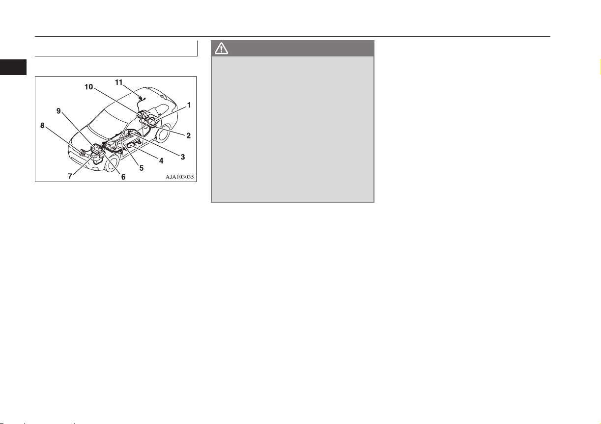
High-Voltage components
2
1- On board charger/DC-DC converter
2- Rear motor
3- Service plug
4- Electric heater*
5- Drive Battery
6- Front motor
7- Generator
8- Air conditioner compressor
9- Power drive unit (PDU)
10- Rear electric motor control unit (MCU)
11- Normal charge port/Quick charge port
E00205500032
WARNING
The Plug-in Hybrid EV System uses high
l
voltage up to DC 300 volt. The system can
be hot during and after starting and when
the vehicle is shut off. Be careful of both
the high voltage and the high temperature. Follow the warning labels that are
attached to the vehicle.
Always assume the high voltage battery
l
and associated components are energized
and fully charged.
Never perform servicing when READY
l
indicator is illuminating or when the
charging indicator is illuminating or
flashing because the high-voltage system
is operating.
2-08
General information
OGGE16E1
Page 23

For persons with electro-medical apparatus such as implantable cardiac pacemaker or implantable cardioverter-defibrillator
For persons with electro-medical apparatus such as implantable cardiac pacemaker or implantable cardioverter-defibrillator
WARNING
Before normal charging:
l
Before you perform charging work, ask the manufacturer of your electro-medical apparatus about the effect from charging work. Charging may
•
affect the operation of your electro-medical apparatus.
Refer to “Normal charging (charging method with rated AC 220-240 V outlet)” on page 3-10.
Refer to “Quick charging (charging method with quick charger)” on page 3-16.
When the normal charging
l
Observe the following precautions for normal charging.
•
During charging, do not close the implantation portion of electro-medical apparatus such as implantable cardiac pacemaker or implantable
•
cardioverter defibrillator to the charge connector, EV charging cable, control box and normal charging station.
Do not stay inside the vehicle.
•
Do not get in the vehicle (including the luggage comapartment) to take out something or for other purposes.
•
Refer to “Normal charging (charging method with rated AC 220-240 V outlet)” on page 3-10.
Do not perform quick charging and to keep away from a quick charger
l
Please observe the following precautions.
•
There is a possibility that electromagnetic waves affect the operation of the electro-medical apparatus.
Please do not use a quick charger.
•
Keep away as much as possible from the place where the quick charger is stored.
•
If you approach it carelessly, leave quickly without standing still.
Please ask someone to perform the quick charging if necessary.
•
Refer to “Quick charging (charging method with quick charger)” on page 3-16.
Do not bring your body close to the foot area of the rear seat and do not stay in the luggage compartment while the vehicle is running. Also, do not
l
allow persons using an electro-medical apparatus to stay in the luggage compartment while the vehicle is running. The operation of electro-medical
apparatus may be affected.
When using the keyless operation system, please observe following precautions.
l
People with implantable cardiac pacemakers or implantable cardiovascular-defibrillators should not go near the exterior transmitters (A) or the
•
interior transmitters. The radio waves used by the keyless operation system could adversely affect implantable cardiac pacemakers or implantable cardiovascular-defibrillators.
When using electro-medical devices other than implantable cardiac pacemakers or implantable cardiovascular-defibrillators, contact the electro-
•
medical device manufacturer ahead of time to determine the affects of radio waves on the devices. Electromedical device operations could be
adverse effect by radio waves. Refer to “Keyless operation system” on page 4-06.
OGGE16E1
General information
E00205600033
2-09
2
Page 24
Cautions and actions to deal with intense heat
Cautions and actions to deal with intense heat
2
When the ambient temperature is approximately 45 °C or higher, the phenomena described below may occur. Please take the described
l
action.
Even if the ambient temperature is approximately 45 °C or lower, when performing quick charging, driving at high-speed and uphill repeat-
l
edly, the phenomena described below may occur. Please take the described actions.
E00203001128
Approx. ambient
temperature
Approx. 45 °C or
higher
Startup and driving
Charging and battery
Phenomena
The motor output is restricted and the vehicle perform-
l
ance may be decreased. Then, the “PROPULSION POWER IS REDUCED” warning display* may be displayed.
Charging time becomes longer, charging may not be pos-
l
sible or it may stop on the way.
Corrective action
Stop the vehicle at a safe
l
place if needed with the plugin hybrid EV system started.
Park in a well-ventilated,
l
shady place.
NOTE
*: Refer to “PROPULSION POWER IS REDUCED warning display” on page 6-38. Display of the “PROPULSION POWER IS REDUCED” warning
l
display does not indicate a malfunction.
Cautions and actions to deal with intense cold
When the ambient temperature is approximately -15 °C or lower, the phenomena described below may occur. Please take the described
l
corrective action.
2-10
General information
OGGE16E1
E00203101158
Page 25

Cautions and actions to deal with intense cold
Approx. ambi-
ent temperature
Approx. -15 °C or
lower
Approx. -30 °C or
lower
Startup and driving
Charging and battery
Startup and driving
Phenomena Corrective action
The motor output is restricted and the vehicle performance
l
may be decreased. Then, the “PROPULSION POWER IS
REDUCED” warning display*1 may be displayed.
Regenerative braking performance may be decreased.
l
Charging time becomes longer.
l
Complete charging may not be possible.
l
The Plug-in Hybrid EV system may not start.
l
Then, blinking of the ready indicator*2 may continue and
“BATTERY TOO COLD” may be displayed on the multi
information display.*
The motor output may be restricted and the regenerative
l
braking performance may be decreased or lost when
“BATTERY TOO COLD” is displayed.*
3
3
Keep driving if you can drive at
l
a similar speed as the surrounding vehicles.
If you cannot drive at a similar
speed as surrounding vehicles,
stop the vehicle in a safe place
and charge the drive battery.
When braking, depress the
l
brake pedal harder.
When you have finished driv-
l
ing, charge the drive battery before its temperature falls.
In the daytime, wait for the
l
temperature to rise, restart the
plug-in hybrid EV system.
On vehicles equipped with both
l
MITSUBISHI Remote control
and electric heater, if low temperature is predicted, even if the
drive battery is fully charged,
connect EV charging cable beforehand.
The drive battery is automati-
cally warmed up*4.
Immediately stop the vehicle in
l
a safe place.
Also, when braking, depress the
brake pedal harder.
2
OGGE16E1
General information
2-11
Page 26
Cautions and actions to deal with intense cold
Approx. ambi-
ent temperature
2
Phenomena Corrective action
Approx. -30 °C
or lower
Charging and battery
Charging may become impossible or it may stop on the
l
way.
In the daytime, wait for the
l
temperature to rise, restart the
plug-in hybrid EV system.
CAUTION
“BATTERY TOO COLD” is displayed*3, contact a MITSUBISHI MOTORS Authorized Service Point.
l
Blinking of the ready indicator*2 continues and “BATTERY TOO COLD” is displayed*3 on the multi information display with vehicle conditions, the drive
l
battery cannot be warm up.
NOTE
*1: Refer to “PROPULSION POWER IS REDUCED warning display” on page 6-38.
l
Display of the “PROPULSION POWER IS REDUCED” warning display does not indicate a malfunction.
*2: Refer to “Ready indicator” on page 6-44.
l
*3: Refer to “Warning display list” on page 6-24.
l
*4: To warm up the drive battery, you should perform to register the wireless LAN device (which conforms to IEEE 802.11 b and supports iOS or Android)
l
for MITSUBISHI Remote Control to the vehicle. If the information of “
soon as possible.
Refer to “MITSUBISHI Remote Control*” on page 3-23.
If the warming up of the drive battery is activated during home or public charging device (EVSE: Electric Vehicles Supply Equipment) charging, the charging and warming up of the drive battery may be stopped.
While warming up the drive battery, the following phenomena may occur.
The operation sound of on board equipment and the state of charge is displayed on the multi information display.
•
Refer to “Charging from rated AC 220-240 V outlet” on page 3-12.
Inside of the vehicle may be heated automatically.
•
The drive battery may not become full charge, or the remaining capacity of drive battery may decrease.
•
” mark on the wireless LAN device is displayed, connect the EV charging cable as
2-12
General information
OGGE16E1
Page 27
Fuel selection
Fuel selection
E00200104712
Except for vehicles for Russia
Unleaded petrol octane number
Recommended
Vehicles for Russia, this vehicle’s engine is
designed to provide satisfactory performance
by using unleaded petrol octane number 98
RON or higher. In order to maintain engine
performance and exhaust system durability,
use unleaded petrol octane number 98 ron or
higher.
l
(EN228)
95 RON or higher
Vehicles for Russia
fuel
Unleaded petrol octane number
(EN228)
98 RON or higher
CAUTION
The use of leaded fuel can result in serious
damage to the engine and catalytic converter. Do not use leaded fuel.
NOTE
Vehicles for Russia, if less than unleaded
l
petrol 98 RON is used, it may be negatively
influenced to the catalytic converters.
Use unleaded petrol 98 RON or higher except for in case emergency that is not available the unleaded petrol 98 RON or higher on
journey etc.
Poor quality petrol can cause problems such
l
as difficult starting, stalling, engine noise
and hesitation. If you experience these problems, try another brand and/or grade of petrol.
If the check engine warning lamp flashes,
have the system checked as soon as possible
at a MITSUBISHI MOTORS Authorized
Service Point.
E10 type petrol
The petrol engine are compatible with E10
type petrol (containing 10 % ethanol) conforming to European standards EN 228.
CAUTION
Do not use more than 10 % concentration of
l
ethanol (grain alcohol) by volume.
Use of more than 10 % concentration may
lead to damage to your vehicle fuel system,
engine, engine sensors and exhaust system.
Filling the fuel tank
WARNING
When handling fuel, comply with the safe-
l
ty regulations displayed by garages and
filling stations.
Gasoline is highly flammable and explo-
l
sive. You could be burned or seriously injured when handling it. When refueling
your vehicle, always put the operation
mode of the power switch in OFF and
keep away from flames, sparks, and
smoking materials. Always handle fuel in
wellventilated outdoor areas.
Before removing the fuel cap, be sure to
l
get rid of your body’s static electricity by
touching a metal part of the car or fuel
pump. Any static electricity on your body
could create a spark that ignites fuel vapour.
Perform the whole refueling process
l
(opening the fuel tank filler door, removing the fuel cap, etc.) by yourself. Do not
let any other person come near the fuel
tank filler. If you allowed a person to help
you and that person was carrying static
electricity, fuel vapour could be ignited.
Do not perform charging and refueling at
l
the same time. If you charged with static
electricity, fuel vapour could be ignited by
the discharge spark.
E00200204191
2
OGGE16E1
General information
2-13
Page 28
Filling the fuel tank
WARNING
Do not move away from the fuel tank fill-
l
2
er until refueling is finished. If you moved
away and did something else (for example, sitting on a seat) part-way through
the refueling process, you could pick up a
fresh charge of static electricity.
Be careful not to inhale fuel vapour. Fuel
l
contains toxic substances.
Keep the doors and windows closed while
l
refueling the vehicle. If they were open,
fuel vapour could get into the cabin.
If the tank cap must be replaced, use only
l
a MITSUBISHI MOTORS genuine part.
CAUTION
Refill the fuel more than 15 litres at once
•
within three months. If the fuel remaining
display will be below half, you can refill
the fuel more than 15 litres certainly.
Refer to “Fuel remaining display screen”
on page 6-10.
Fuel tank capacity
45 litres
Refueling
1. Before filling with fuel, stop the plug-in
CAUTION
The fuel in the fuel tank may not be con-
l
sumed and it may stagnate for a long time
depending on the use situation of the vehicle, the quality of fuel may change, and it
may have a bad influence on the engine or
the parts of a fuel system.
Observe the following instructions for prevention.
Press the battery charge switch to start the
•
engine within three months at once.
Refer to “Battery charge switch” on page
7-22.
hybrid EV system.
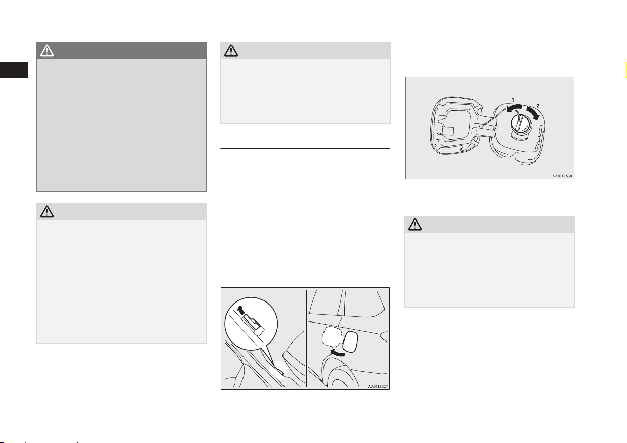
2. The fuel tank filler is located on the rear
left side of your vehicle.
Open the fuel tank filler door by pulling
the release lever located on the side of
the driver’s seat.
3. Open the fuel tank filler tube by slowly
turning the cap anticlockwise.
1- Remove
2- Close
CAUTION
Since the fuel system may be under pressure,
l
remove the fuel tank filler tube cap slowly.
This relieves any pressure or vacuum that
might have built up in the fuel tank. If you
hear a hissing sound, wait until it stops before removing the cap. Otherwise, fuel may
spray out, injuring you or others.
2-14
General information
OGGE16E1
Page 29

Installation of accessories
NOTE
While filling with fuel, hang the fuel cap on
l
the hook (A) located on the inside of the fuel
tank filler door.
4. Insert the gun in the tank port as far as it
goes.
CAUTION
Do not tilt the gun.
l
5. When the gun stops automatically, do
not fill with fuel any more.
6. To close, turn the fuel cap slowly clockwise until you hear clicking sounds, then
gently push the fuel tank filler door
closed.
Installation of accessories
E00200302143
We recommend you to consult your
MITSUBISHI MOTORS Authorized Service
Point.
The installation of accessories, optional
l
parts, etc., should only be carried out
within the limits prescribed by law in
your country, and in accordance with the
guidelines and warnings contained within the documents accompanying this vehicle.
Installing electric components incorrect-
l
ly could lead to a fire. Refer to the
“Modification/alterations to the electrical or fuel systems” section within this
owner’s manual.
Using a cellular phone or radio set inside
l
the vehicle without an external antenna
may cause electrical system interference,
which could lead to unsafe vehicle operation.
Tyres and wheels which do not meet
l
specifications must not be used.
Refer to the “Specifications” section for
information regarding wheel and tyre
sizes.
Important points!
Due to large number of accessory and replacement parts of different manufactures
available in the market, it is not possible, not
only for MITSUBISHI MOTORS, but also
for a MITSUBISHI MOTORS Authorized
Service Point, to check whether the attachment or installation of such parts affects the
overall safety of your MITSUBISHI-vehicle.
Even when such parts are officially authorized, for example by a “general operators
permit” (an appraisal for the part) or through
the execution of the part in an officially approved manner of construction, or when a
single operation permit following the attachment or installation of such parts, it cannot be
deduced from that alone, that the driving
safety of your vehicles has not been affected.
2
OGGE16E1
General information
2-15
Page 30
Modification/alterations to the electrical or fuel systems
Consider also that there basically exists no liability on the part of the appraiser or the official. Maximum safety can only be ensured
2
with parts recommended, sold and fitted or
installed by a MITSUBISHI MOTORS authorized Service Point (MITSUBISHI
MOTORS GENUINE replacement parts and
MITSUBISHI MOTORS accessories). The
same also pertains to modifications of
MITSUBISHI vehicles with respect to the
production specifications. For safety reasons,
do not attempt any modifications other than
those that follow the recommendations of a
MITSUBISHI MOTORS authorized Service
Point.
Modification/alterations to
the electrical or fuel systems
MITSUBISHI MOTORS CORPORATION
has always manufactured safe, high quality
vehicles. In order to maintain this safety and
quality, it is important that any accessory that
is to be fitted, or any modifications carried
out which involve the electrical or fuel systems, should be carried out in accordance
with MITSUBISHI guidelines.
E00200400368
CAUTION
If the wires interfere with the vehicle body
l
or improper installation methods are used
(protective fuses not included, etc.), electronic devices may be adversely affected, resulting in a fire or other accident.
Genuine parts
E00200500499
MITSUBISHI MOTORS has gone to great
lengths to bring you a superbly crafted automobile offering the highest quality and dependability.
Use MITSUBISHI MOTORS GENUINE
Parts, designed and manufactured to maintain
your MITSUBISHI MOTORS automobile at
top performance. MITSUBISHI MOTORS
GENUINE Parts are identified by this mark
and are available at all MITSUBISHI
MOTORS Authorized Service Points.
Safety and disposal information for used engine oil
E00200601383
WARNING
Prolonged and repeated contact may
l
cause serious skin disorders, including
dermatitis and cancer.
Avoid contact with the skin as far as pos-
l
sible and wash thoroughly after any contact.
Keep used engine oils out of reach of chil-
l
dren.
Protect the environment
It is illegal to pollute drains, water courses
and soil. Use authorized waste collection facilities, including civic amenity sites and garages providing facilities for disposal of used
oil and used oil filters. If in doubt, contact
your local authority for advice on disposal.
2-16
General information
OGGE16E1
Page 31

Disposal information for used batteries
E00201301055
Your vehicle contains batteries and/or accumulators.
Do not mix with general
household waste.
For proper treatment, recov-
ery and recycling of used
batteries, please take them to applicable collection points, in accordance with your national legislation and the Directives
2006/66/EC.
By disposing of these batteries correctly, you
will help to save valuable resources and prevent any potential negative effects on human
health and the environment which could otherwise arise from inappropriate waste handling.
Disposal information for used batteries
2
OGGE16E1
General information
2-17
Page 32

OGGE16E1
Page 33

Charging
Charging..............................................................................................3-02
Battery.................................................................................................3-04
Basic knowledge for charging.............................................................3-04
EV charging cable...............................................................................3-07
Normal charging (charging method with rated AC
220-240V outlet).............................................................................3-10
Quick charging (charging method with quick charger)*.................... 3-16
Charging troubleshooting guide..........................................................3-20
MITSUBISHI Remote Control*......................................................... 3-23
3
OGGE16E1
Page 34

Charging
Charging
Your vehicle is equipped with a charge port and a charging cable (EV charging cable)*1 for charging with a AC 220-240V outlet.
3
You can also charge your vehicle using 220-240V home or public charging device (EVSE*2) compatible with Outlander PHEV.
As an optional feature, your vehicle may come equipped with an additional quick charge port to be used with a CHAdeMO quick charger.
E08303801136
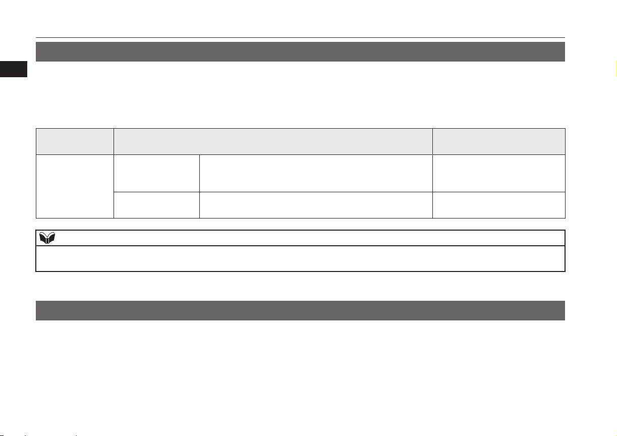
Category Charge port Charge connector Charging Source
Normal charging
(AC 220-240V)
When using a gen-
uine charging ca-
ble
3-02
Charging
Right rear side of vehicle
OGGE16E1
220-240V household outlet
(Refer to “Charging from rat-
ed AC 220-240 V outlet” on
page 3-12)
Charging time
with fully dis-
charged battery
230V/10A: About
5 hours*
230V/8A: About
6.5 hours*
3
3
Refer-
ence
p.3-10
Page 35

Charging
Category Charge port Charge connector Charging Source
Normal charging
(AC 220-240V)
When using a
home or public
charging device
(EVSE*2)
Right rear side of vehicle
Home or public charging de-
vice
Quick charging
(charging method
with quick charg-
1
er)*
Right rear side of vehicle
Public charging stations
where available
*1
: optional equipment
*2
: EVSE = Electric Vehicle Supply Equipment
*3
: Use this time as a guide because the rated AC voltage and the rated current value may differ from country to country.
Charging time
with fully dis-
charged battery
230V/16A: About
3.5 hours*
3
About 30 minutes
for 80 % charge
Refer-
ence
3
p.3-10
p.3-10
OGGE16E1
Charging
3-03
Page 36

Battery
*4
: When using a EVSE to which charging cable is not attached, use a Mode 3 charging cable for Outlander PHEV (Type 2 to 1) -available
separately. For details, please consult a MITSUBISHI MOTORS Authorized Service Point.
Alternately, the drive battery can be almost fully charged by turning on the battery charge switch while the vehicle is running or stopping. Refer
to “Battery charge switch” on page 7-22.
3
Battery
E08300101079
There are two types of batteries installed in
your vehicle: a drive battery for operating the
motor (electric motor unit) and air conditioning as well as an auxiliary battery for starting
the Plug-in Hybrid EV system and operating
the lamps, wipers, etc.
This chapter explains charging of the drive
battery.
3-04
Charging
NOTE
The auxiliary battery is automatically charg-
l
ed while the ready indicator is illuminated or
during charge for the drive battery.
Refer to “Ready indicator” on page 6-44.
If the auxiliary battery is flat, the Plug-in
l
Hybrid EV system cannot be started.
Refer to “Emergency starting” on page
9-02.
Basic knowledge for charging
E08300201168
There are two types of charging: normal
charging and quick charging.
OGGE16E1
Normal charging is performed through the on
board charger using rated AC 220-240V outlet as the power source
The rated AC voltage may differ from country to country.
Page 37

Basic knowledge for charging
WARNING
To reduce the risk of electric shock or fire
l
due to electric leak, always use an earthed
outlet protected by a residual current detector, rated for amperage equal to or
greater than the value specified by
MITSUBISHI MOTORS, and that is connected to a dedicated branch circuit. If
the circuit is shared, and another electrical device is being used at the same time
the vehicle is charging, the circuit may
heat abnormally, the breaker may trip
and the circuit may cause adverse interference on the household electrical appliances such as TVs and audio systems.
It is possible to charge even in rain or
l
snow. However, be sure to pay attention
to the following:
Do not touch normal charging port,
•
normal charge connector, outlet and
plug with wet hands.
Keep away from water when connect-
•
ing the normal charging port, normal
charge connector, outlet and plug.
Do not perform the charging in the out
•
of doors when heavy rain, heavy snow,
strong winds, and when bad weather is
expected.
Do not charge if there is possibility a
•
lightning strike. When thunder rumbling begins suddenly during normal
charging, do not touch the vehicle and
the EV charging cable and turn off the
breaker.
WARNING
If water goes into the normal charging
l
port or the normal charge connector, it
could cause a short circuit, a fire and an
electric shock.
Be sure to completely close the charging
lid and the inner lid and do not leave the
EV charging cable in an outdoors.
If the connected part of the charging plug
l
has been buried in snow while charging,
turn off the hand switch or the breaker
connected with the outlet first, then remove the snow and disconnect the charging plug. If your vehicle body has been
buried in snow while charging, remove
the snow and then disconnect the charge
connector.
When you perform the normal charging
l
at away from home, some normal chargers may not correspond to your vehicle.
Consult an administrator or a maker of
the normal charger that it corresponds to
your vehicle before using it. Also perform
normal charging according to the operating procedure indicated on the body of
normal charger.
Do not open the charging lid for anything
l
other than charging and using the external power feed.
CAUTION
Do not attempt to perform a jump start on
l
the auxiliary battery at the same time that the
drive battery is being charged. Doing so may
damage the vehicle or charging cable and
could cause injury.
Refer to “Emergency starting” on page
9-02.
NOTE
If you open the charging lid with the opera-
l
tion mode of the power switch is ON, a buzzer sounds approximately 10 minutes intermittently to alert the charging cannot be started. If you close the charging lid or put the
operation mode in OFF, the buzzer stops.
If you insert the charge connector to the
l
charge port with the operation mode is ON,
a buzzer sounds continuously approximately
10 minutes to alert the charging cannot be
started.
If you pull the charge connector out or put
the operation mode in OFF, the buzzer stops.
Repeatedly performing only quick charging
l
may reduce the battery capacity.
In usual charge, normal charging is recommended.
To maintain the capacity of the drive battery,
l
the following is recommended:
If you repeatedly perform only quick
•
charging, fully charge the vehicle in normal charging mode every two weeks.
3
OGGE16E1
Charging
3-05
Page 38

Basic knowledge for charging
NOTE
Do not repeat charging near the full
•
charge level.
The quick charging gives priority when the
l
3
normal charging and the quick charging are
performed at the same time. At this time, the
normal charging will be stopped.
Even if the operation mode of the power
l
switch is OFF, you may hear the operating
sound of the cooling fan for cooling the
drive battery during charging.
This is not a malfunction.
If your vehicle is not used for a long time,
l
check the energy level gauge every 3
months. If the gauge shows 0, charge the
drive battery until some indication appears.
Alternately, put the operation mode of the
power switch in “ON” to start the engine automatically, wait for the engine to stop automatically, then put the operation mode of the
power switch in “OFF”.
In the event of an electrical power outage
l
while charging, charging restarts automatically with the restoration of electricity.
Charging port courtesy lamp
The charging port courtesy lamp (A) illuminates when the charging lid is opened while
the select position is in “P” (PARK) position.
It goes off automatically after a few seconds.
If you want to turn on it again, press the
charging port courtesy lamp switch (B).
E08304300027
When charging is started, the charging port
courtesy lamp blinks 3 times and then goes
off automatically.
NOTE
The charging port courtesy lamp illuminat-
l
ing time can be adjusted.
For details, please consult a MITSUBISHI
MOTORS Authorized Service Point.
If the MITSUBISHI Remote Control (if so
l
equipped) is operated when the charging
port courtesy lamp is off, the lamp may illuminate.
3-06
Charging
OGGE16E1
Page 39

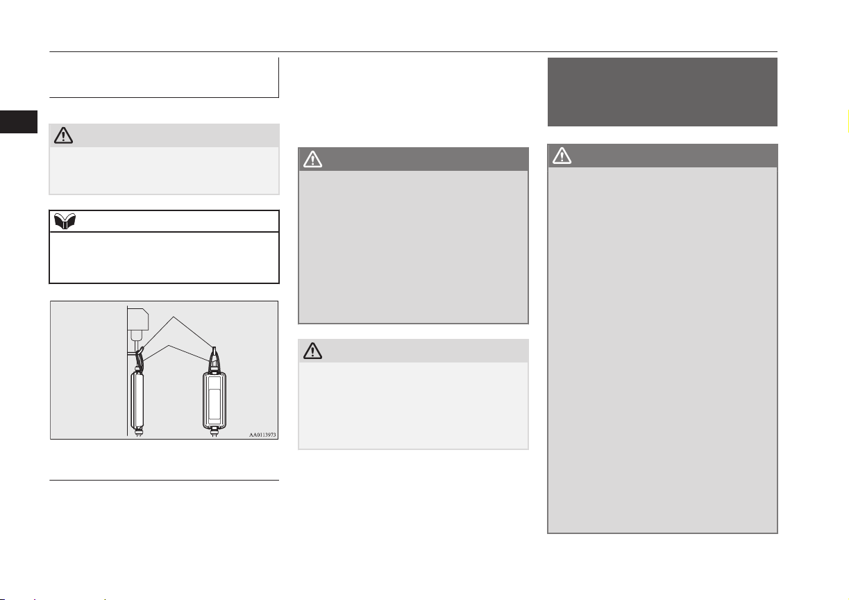
Indicator (LED) and button
E
A
B
C
D
F
G
H
I
EV charging cable
EV charging cable
E08301101151
Your vehicle is equipped with an EV charging cable that consists of a cable (A), control box (B), EV charging cable plug (C), and normal charge
connector (D).
3
E- Manual stop button G ( )- POWER indicator
F- Stop indicator
I ( )- CHARGING indicator
To stop charging, simply press manual stop button (E) and stop indicator (F) is illuminated. Re-connect the EV charging cable plug (C) to charge
H ( )-
FAULT indicator
again.
POWER (G), FAULT (H) and CHARGING (I) indicators located on the control box will illuminate/blink in response to the following conditions:
OGGE16E1
Charging
3-07
Page 40

EV charging cable
: Illuminates : Blinking : Not illuminated
POWER
3
POWER
FAULT
FAULT
CHARGING
CHARGING
Operating condition
Every time the charging cable plug (C) is connected to an outlet, all indication lamps illuminate for 0.5 seconds.
After initial processing is completed, when the normal charge connector is not connected to
the charge port, or the normal charge connector is connected to the charge port but charging
is not being performed.
While the drive battery is being charged.
When charging is completed.
Abnormal operating condition and corrective action
When an electric leakage occurs or the EV charging cable malfunctions
Stop using the EV charging cable immediately and contact a MITSUBISHI MOTORS Authorized Service Point.
When the EV charging cable malfunctions
Stop using the EV charging cable immediately and contact a MITSUBISHI MOTORS Authorized Service Point.
If the control box indication lamp does not illuminate after connecting the charging cable
plug to the outlet, check the circuit breaker for the outlet. If the breaker has tripped, the circuit may not be suitable for use with EV charging cable. You should have a licensed electrician inspect and repair the electrical circuit. If the breaker is not tripped, stop using the EV
charging cable and contact a MITSUBISHI MOTORS Authorized Service Point.
3-08
Charging
OGGE16E1
Page 41
EV charging cable
WARNING
If the POWER or CHARGING indicator does not illuminates or the FAULT indicator blinks or illuminates during normal charging, please contact
l
a MITSUBISHI MOTORS Authorized Service Point.
Do not charge when the EV charging cable is coiled up.
l
The cable may be heated and resulting in fire.
Do not alter or disassemble the EV charging cable. Doing so could cause fire, an electric shock or injury.
l
Be sure to install the cap to the normal charge connector and store the EV charging cable in a place where the cable is not exposed to water or dust.
l
Entry of foreign matter such as water or dust in the metal terminal of the normal charge connector or charging cable plug may cause a fire or
malfunction.
Never force the connection if the EV charging cable or connector shows damage or is not easily connected due to foreign material entering the
l
connector or the outlet. And never use an outlet that is worn, damaged, or will not hold the plug firmly. Doing so could cause fire, an electric shock,
or short circuit.
Pay attention to the following for handling the EV charging cable.
l
Damage to the cable could cause fire, an electric shock, or short circuit.
Do not drop the cable or do not give strong impact to it.
•
Do not pull or bend with undue force.
•
Do not twist.
•
Do not drag.
•
Do not put an object on top.
•
Do not put the cable close to a heating unit including heater.
•
CAUTION
Do not connect the normal charge cable to an outlet that has a lower rating than the current value described on the control box.
l
3
NOTE
All indicators are illuminated momentarily for confirming operation when the charging cable plug is inserted into an outlet. After that the POWER indicator
l
and the CHARGING indicator is continuously illuminated.
The CHARGING indicator will start to blink when the charging is completed. The POWER indicator is continuously illuminated while the charging cable
l
plug is inserted into an outlet.
OGGE16E1
Charging
3-09
Page 42
Hook
Rope
Normal charging (charging method with rated AC 220-240V outlet)
Handling and storing the control box
3
CAUTION
While charging, prevent damage to the con-
l
trol box by attaching a rope as shown in the
following illustration.
NOTE
Use a hook with a load capacity over 4 kg.
l
Check that the rope and hook have no dam-
l
age and are not loose before use.
Cleaning the EV charging cable
1. Lightly wipe these off with a soft cloth
soaked in a mild soap and water solution.
E08301201093
E08301301065
2. Wipe off all the detergent with a soft
cloth dipped in fresh water and thoroughly wrung out.
3. Wipe all moisture off and dry in a shaded, well-ventilated area.
WARNING
When cleaning, be sure to remove the
l
charging cable plug and the normal
charge connector from the outlet. Do not
connect or disconnect the plug and the
connector with wet hands. Doing so could
cause an electric shock.
Do not expose the metal terminal of the
l
normal charge connector or the charging
cable plug to water or neutral detergent.
Using in wet with water could cause a fire
or an electric shock.
CAUTION
Never use benzine, petrol, or other organic
l
solvents, or acid or alkaline solvents. Doing
so could cause deformation, discolour, or
malfunction. Also, these substances may be
present in various cleaners, so check carefully before using.
Normal charging (charging
method with rated AC
220-240V outlet)
E08300901165
WARNING
For safety, do not allow children or people
l
who are not familiar with charging to
charge for themselves. Also, do not use
the normal charge connector within reach
of children.
Persons who use electro-medical appara-
l
tus such as implantable cardiac pacemaker or implantable cardioverter defibrillator must check effect from charging with
the manufacturer of electro-medical apparatus. Electro-medical apparatus operations could be affected by charging.
If you use electro-medical apparatus such
l
as implantable cardiac pacemaker or implantable cardioverter-defibrillator, be
careful the following precautions.
During charging, do not allow implan-
•
ted electro-medical apparatus such as
cardiac pacemaker or implantable cardioverter defibrillator to be close to the
charge connector, EV charging cable,
control box and normal charging station.
Do not stay inside the vehicle.
•
Do not get in the vehicle (including the
•
luggage compartment) to take out
something or for other purposes.
3-10
Charging
OGGE16E1
Page 43

Normal charging (charging method with rated AC 220-240V outlet)
WARNING
Do not open the rear hatch, for exam-
•
ple to remove or place an item in the
cargo area.
Charging may affect the operation of electric medical devices and result in serious
personal injury or death.
Do not charge when the EV charging ca-
l
ble is coiled up.
Doing so the cable may be heated and this
might result in fire.
Before charging, make sure that there is
l
no foreign matter such as dust at the normal charge port and the normal charge
connector.
At this time, do not touch the normal
charge port.
When the normal charge connector is
l
connected to the charge port, prevent foreign matter such as water or dust from
entering in the connection.
Connection with foreign matter such as
water or dust may cause fire or an electric
shock. Do not perform charging if there
might be strong exposure to water at the
connection.
Never pull the cable to remove the plug.
l
And never submerge the EV charging
connector, control box or plug in water.
Please observe the following in order to
l
prevent accidents during charging such as
electrocution.
Only use the EV charging cable that is
•
supplied with the vehicle.
WARNING
Do not charge another vehicle by the
•
EV charging cable. The cable may
overheat and result in a fire.
When charging outdoors, make sure to
•
use an outlet that is protected from water entering.
Do not perform charging with the car
•
cover.
Do not connect or disconnect the plug
•
and connector with wet hands.
While it is normal for the connector and
l
charging cable to become warm during
charging, discontinue use immediately if
the connector or charging cable becomes
hot to the touch.
While it is normal for the control box to
l
become warm during charging, discontinue use immediately if the control box becomes hot to the touch.
If abnormal smells are detected or the ve-
l
hicle produces smoke, quickly stop charging.
Do not perform charging in a poorly ven-
l
tilated area or in an enclosed area. Keep
sparks, cigarettes, and flames away from
the auxiliary battery.
Flammable gas generated from the auxiliary battery during charging may be trapped, resulting in explosion.
If charging is inevitably required, ventilate the area well.
WARNING
Grasp the normal charge connector when
l
connecting or disconnecting the EV
charging cable.
Grasping the cable may damage the cable
and could cause an electric shock, short
circuit, and/or fire.
CAUTION
During charging, the cooling fans inside the
l
engine room may automatically be operated
even if the operation mode of the power
switch in OFF.
Keep your hands away from the cooling fan
during charging.
Do not perform charging from other power
l
source like a generator. Doing so could
cause a malfunction.
NOTE
If the charge connector is not easily connec-
l
ted to the charge port due to foreign material
entering, never force the connection. Doing
so could damage the charging equipment or
the vehicle. Please contact a MITSUBISHI
MOTORS Authorized Service Point.
The on board charger is only for rated AC
l
220-240V outlets.
3
OGGE16E1
Charging
3-11
Page 44

Normal charging (charging method with rated AC 220-240V outlet)
NOTE
When connecting or disconnecting the nor-
l
mal charge connector, insert/pull out the
3
connector straight.
Also, do not incline or twist the connector.
Doing so could cause a bad connection or
malfunction.
Make sure to lock the doors to prevent theft,
l
etc. during charging.
Charging from rated AC 220-240 V outlet
1. Firmly apply the parking brake, press the
electrical parking switch, and shift to
“P” (PARK) position.
2. Turn off electrical equipment such as
lamps and put the operation mode of the
power switch in OFF.
E08301001222
3. After unlocking the charging lid by using the central door locks, keyless entry
system or keyless operation function,
push the rear portion of the charging lid
(A) until it clicks, and open the charging
lid.
4. Press the tab (B) to open the inner lid
(C).
WARNING
It could cause electric leak, a fire or elec-
l
tric shock by entering water or dust into
the normal charge port.
Do not touch the metal terminal of the
l
normal charge port (D) and the normal
charge connector.
Doing so could cause an electric shock
and/or malfunction.
NOTE
There is a hole on the charge port for water
l
drainage. If this hole is blocked and water
gets trapped in the charge port, do not
charge. Please contact a MITSUBISHI
MOTORS Authorized Service Point.
If the charge port is frozen, melt the ice us-
l
ing a hair drier. Forcing the charge connector to connect while frozen could result in
malfunction.
5. Insert the charging cable plug into an
outlet.
WARNING
Make sure that the plug is inserted all the
l
way into the outlet before use. If charging
is continued in the state where it is not
fully inserted the plug, there is a possibility of generating abnormal heat and resulting in a fire.
3-12
Charging
OGGE16E1
Page 45

Denmark 250V/13A
UK, Ireland 250V/13A
Germany, Spain, France, Sweden, etc.
250V/16A
Industrial plug for Europe 250V/16A
Switzerland 250V/10A
Italy 250V/10 A
Normal charging (charging method with rated AC 220-240V outlet)
WARNING
To prevent an electric shock or fire due to
l
electric current leak, perform charging
using a waterproofed outlet with earthing
which is connected to an earth leakage
circuit breaker.
To reduce the risk of electric shock or fire
l
due to electric leak, always use an outlet
protected by a residual current detector,
rated for amperage equal to or greater
than the value specified by MITSUBISHI
MOTORS, and that is connected to a
dedicated branch circuit. If the circuit is
shared, and another electrical device is
being used at the same time the vehicle is
charging, the breaker may trip and the
circuit may cause adverse interference on
MCB (Moulded Circuit Board) and
household electrical appliances such as
TVs and audio systems.
If a multi plug adapter is connected and
l
used with the EV charging cable together
with other devices, the outlet may overheat, resulting in a fire.
Do not use a multi type outlet to prevent
l
an electric shock or fire. There is no guarantee of safety because you cannot make
an earth connection in some multi type
outlet and it is not a dedicated type outlet.
Use an outlet for EV charging with water-
l
proofing processing installed if the installed position is outdoors or may get wet by
rain etc.
CAUTION
Use the outlet that is installed approx. 1 me-
l
ter above the ground. If the outlet position is
too low, the control box may touch the
ground, which may lead to troubles such as
submersion in water or getting trampled on.
NOTE
The shape of the charging cable plug and
l
outlet may differ from country to country as
shown in the illustration.
Use the following outlets.
l
Check if the outlet on your vehicle corre-
l
sponds with an outlet that is installed in the
following places.
In your house etc.
•
In a parking lot or garage
•
3
OGGE16E1
Charging
3-13
Page 46
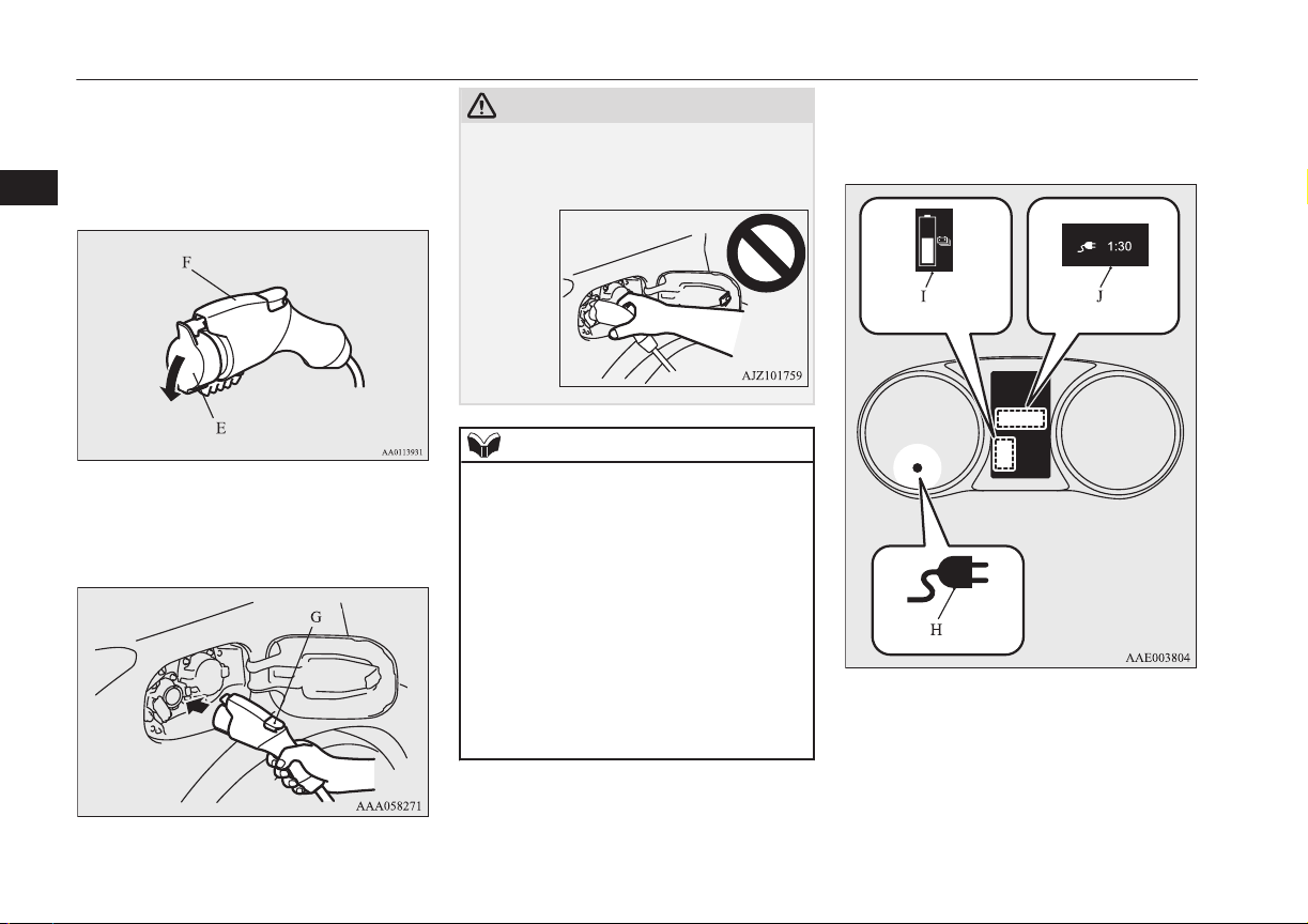
Normal charging (charging method with rated AC 220-240V outlet)
6. Remove the cap (E) on the normal
charge connector (F) and make sure that
there is no foreign matter such as dust at
the end of the normal charge connector
3
and the normal charge port.
7. Connect the normal charge connector
until a click sound is heard without
pressing the button (G).
CAUTION
Do not clasp the top of normal charge con-
l
nector. It could cause injury to touch the
protrusion on the charging lid.
NOTE
If the operating mode of the power switch is
l
ON with the EV charging cable remains
connected to the normal charge port, the
plug-in hybrid EV system does not turn ON.
Do not connect or disconnect the normal
l
charge connector repeatedly in a short period. Charging may not be started.
If you want to turn the operation mode to
l
“OFF” after “ACC” or “ON” position in order to use the electrical device such as audio
during charging, make sure that the select
position is in “P”, press the power switch to
turn “OFF” without depressing the brake
pedal.
8. Make sure that the charging indicator
(H) on the instrument cluster is illuminated.
If the charging indicator is not illuminated, charging has not started.
Make sure that the normal charge port
and the plug are correctly connected, and
perform charging from Step 5 again.
3-14
Charging
OGGE16E1
Page 47
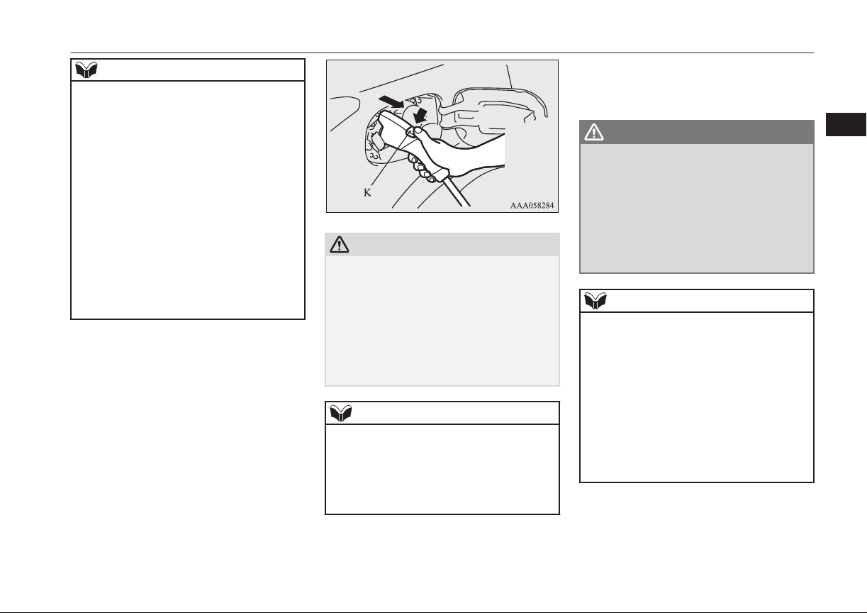
Normal charging (charging method with rated AC 220-240V outlet)
NOTE
When the normal charge connector is con-
l
nected to the charge port, the charging indicator will blink. When charging is started,
the charging indicator is illuminated and the
charging port courtesy lamp blinks 3 times
and then goes off automatically.
If you want to confirm the drive battery level
l
or the predicted charging time during charging, one of the doors is opened or the multi
information display switch is operated, the
drive battery level display (I) appears and
the predicted charging time display (J) appears in the multi information display.
In addition, when the remaining time is less
than 1 hour, the predicted charging time display (J) appears --:-- and does not indicate a
malfunction.
9. Charging is complete when the charging
indicator turns off. Pull out the normal
charge connector while pressing the button (K).
CAUTION
Be sure to check the normal charge connec-
l
tor is removed from the normal charge port.
The vehicle can be driven with the charge
connector inserted when it is not locked
completely which may result in a serious accident.
Be sure the charge connector is removed
completely from the vehicle after the charging is completed.
NOTE
Charging can be stopped half way. In this
l
case, also, pull out the normal charge connector while pressing the button. Pressing
the manual stop button on the control box
can also stop charging.
Refer to “EV charging cable” on page 3-07.
OGGE16E1
10. Close the inner lid and press the rear of
the normal charging lid until it clicks to
close it.
WARNING
After charging, be sure to close the inner
l
lid and the normal charging lid completely.
Be careful that water or dust does not enter in the normal charge port, inner lid
and normal charge connector.
Entry of water or dust could cause electric current leakage, resulting in a fire or
electric shock.
NOTE
Make sure that the inner lid is completely
l
closed.
If the normal charging lid is forcibly closed
without completely closing inner lid, the
hinge on the inner lid may be broken.
When the operation mode is switched to ON
l
while the charging lid is not completely
closed, a warning may be displayed on the
information display of the multi information
display.
Refer to “Warning display list” on page
6-24.
11. Remove the charging cable plug from
the outlet.
12. Install the cap on the normal charge connector.
Charging
3-15
3
Page 48

Quick charging (charging method with quick charger)*
WARNING
After charging, be sure to disconnect the
l
charge connector from the charge port.
3
If the charge connector is only partially
engaged and the connector latch is unlocked, you could put the operation mode
of the power switch in “ON” and the vehicle could start moving. It could lead to an
unexpected accident.
Quick charging (charging
method with quick
charger)*
WARNING
Be sure to use the quick charger applica-
l
ble to CHAdeMO standard and certified
by CHAdeMO association. Use of the other quick charger may cause the fire or
malfunction.
For operation of quick chargers, follow
l
the manual of each quick charger.
If you use electro-medical apparatus such
l
as implantable cardiac pacemaker or implantable cardioverter-defibrillator, be
careful the following precautions.
Please do not use a quick charger.
•
Keep away as much as possible from
•
the place where the quick charger is
stored. If you approach it carelessly,
leave quickly without standing still.
E08301401141
WARNING
Please ask someone to perform the
•
quick charging if necessary.
Before charging, make sure that there is
l
no foreign matter such as dust at the
quick charge port and the quick charge
connector.
At this time, do not touch the quick
charge port.
When the quick charge connector is con-
l
nected to the quick charge port, prevent
foreign matter such as water or dust from
entering in the port.
Connection with foreign matter such as
water or dust may cause fire or an electric
shock. Do not perform charging if there
might be strong exposure to water at the
connection.
During charging, the cooling fans inside
l
the bonnet room may automatically be
operated even if the operation mode of the
power switch is in OFF.
Keep your hands away from the cooling
fan during charging.
NOTE
During quick charging, quick charging is
l
stopped by putting the operation mode of the
power switch in ON.
NOTE
If the charge connector is not easily connec-
l
ted to the charge port due to foreign material
entering, never force the connection. Doing
so could damage the charging equipment or
the vehicle. Contact a MITSUBISHI
MOTORS Authorized Service Point.
The quick charger might be installed in the
l
public parking space, some chargers are not
suitable for this vehicle. Check the manual
of each quick charger when charging.
The charge connector and the EV charging
l
cable stick out of the vehicle body while
charging, so be careful that your body does
not get stuck with them or they do not touch
the next vehicle.
The vehicle equipped with a quick charge
l
port is compatible with most CHAdeMO
(standard for quick charging of electric vehicle originally established in Japan) connectors on charging stations.
Make sure to lock the doors to prevent theft,
l
etc. during charging.
When using a quick charger, make sure that
l
the time available is enough so that the quick
charging can be finished in the time available.
If the power supply of the quick charger is
shut off during quick charging, it could lead
to a vehicle failure.
1. Firmly apply the parking brake, press the
electrical parking switch, then shift the
select position in “P” (PARK) position.
3-16
Charging
OGGE16E1
Page 49

Quick charging (charging method with quick charger)*
2. Turn off electrical equipment such as
lamps and put the operation mode of the
power switch in OFF.
3. After unlocking the charging lid by using the central door locks, keyless entry
system or keyless operation function,
push the rear portion of the charging lid
(A) until it clicks, and open the charging
lid.
4. Press the tab (B) to open the inner lid
(C).
WARNING
Do not leave the inner lid open for a long
l
time.
It could cause an electric leak, a fire or an
electric shock by water or dust entering
into the quick charge port.
Do not touch the metal terminal of the
l
quick charge port (D) and the quick
charge connector.
Doing so could cause an electric shock
and/or malfunction.
CAUTION
Be sure to insert the quick charge connector
l
straight into the quick charge port right up to
the base.
Failure to do so may result in the drive battery not charging or could cause damage to
the charging equipment.
CAUTION
During quick charging, the quick charge
l
connector cannot be removed because it is
locked. Do not touch or remove the quick
charge connector during charging. Doing so,
the quick charge connector might be damaged. If you want to stop the quick charging
on the way, stop the charging according to
the procedures of a quick charger, and remove the quick charge connector after confirming the charging is stopped.
NOTE
There is a hole on the charge port for water
l
drainage. If this hole is blocked and water
gets trapped in the charge port, do not
charge. Contact a MITSUBISHI MOTORS
Authorized Service Point.
If the charge port is frozen, melt the ice us-
l
ing a hair drier. Forcing the charge connector to connect while frozen could result in
malfunction.
5. Connect the quick charge connector in
the quick charge port to begin charging.
For connecting and disconnecting, follow the instruction manual for each
quick charger.
6. Make sure that the charging indicator
(E) on the instrument cluster is illuminated.
3
OGGE16E1
Charging
3-17
Page 50

Quick charging (charging method with quick charger)*
NOTE
If you want to confirm the drive battery level
l
during charging, open one of the doors or
3
If the charging indicator is not illuminated, charging is not started.
Follow the manual of each quick charger.
operate the multi information display switch,
the drive battery level display (F) appears in
the multi information display.
Although the predicted charging time display (G) blinks, the charging time for the
quick charging is about 30 minutes and displayed “--:--” in the screen and you cannot
confirm the remaining charging time.
Operation noise may be heard from the vehi-
l
cle body during quick charging.
This noise comes from the operation of the
drive battery cooling system, and it is not a
malfunction.
Since the drive battery cooling system uses
l
cool air of the air conditioning, the air conditioning is automatically operated.
After quick charging, if the area under the
vehicle is wet, transparent and loose, it is dehumidified water from the air conditioning
and not a malfunction.
7. Charging is complete when the charging
indicator turns off.
Disconnect the quick charge connector
according to the manual of the quick
charger.
CAUTION
As the quick charge connector is heavier in
l
comparison to the normal charge connector,
allowing it to drop could cause damage to
the vehicle or charge connector or personal
injury. When removing the connector, be
sure to pull it out straight and as carefully as
possible.
Do not leave the quick charge connector
l
connected to the quick charge port after
charging.
Doing so, someone might stumble and it
could cause an injury or the quick charge
port might be damaged by playing it.
NOTE
Although it is possible to start the electric
l
motor unit if quick charging has not finished
normally, the charging indicator is continuously blinking. In such a situation, perform
quick charging again and finish it normally
or contact a MITSUBISHI MOTORS Authorized Service Point.
8. Close the inner lid and press the rear of
the normal charging lid until it clicks to
close it.
NOTE
When the quick charge connector is connec-
l
ted to the charge port, the charging indicator
is blinking. When charging is started, the
charging indicator is illuminated.
3-18
Charging
OGGE16E1
Page 51

Quick charging (charging method with quick charger)*
WARNING
After charging, be sure to close the inner
l
lid and the quick charging lid completely.
Be careful that water or dust does not enter in the quick charge port, inner lid and
quick charge connector.
Entry of water or dust could cause fire,
electric shock or short circuit.
After charging, be sure to disconnect the
l
charge connector from the charge port.
If the charge connector is only partially
engaged and the connector latch is unlocked, you could put the operation mode
of the power switch in “ON” and the vehicle could start moving. It could lead to an
unexpected accident.
NOTE
If the operation mode of the power switch is
l
put in ON with the quick charge connector
connected to the quick charge port, the plugin hybrid EV system cannot be started.
Be sure to disconnect the quick charge connector before start.
Charging may be completed before full
l
charge. This is a control for efficient charge
and not a malfunction.
To achieve full charge, repeat charging from
Step 5 again.
NOTE
Make sure that the inner lid is completely
l
closed.
If the quick charging lid is forcibly closed
without completely closing the inner lid, the
hinge on the inner lid may be broken.
3
OGGE16E1
Charging
3-19
Page 52

Charging troubleshooting guide
Charging troubleshooting guide
E08301501142
3
Symptom Possible cause Possible solution
Charging cannot be
started.
Normal charging cannot be started.
The operation mode of the power
switch in ON
The drive battery is already fully
charged.
The temperature of the drive battery is too high or too low to
charge.
The auxiliary battery is discharged.
The vehicle or the charging cable
has a malfunction.
There is no electrical power coming from the outlet.
The charge connector is not connected correctly.
The charge connector was connected and disconnected repeatedly in
a short time.
Put the operation mode of the power switch in “OFF” before charging.
Charging cannot be performed if the drive battery is already fully charged. Charging automatically turns off if the drive battery is fully charged.
Confirm the drive battery temperature.
Refer to “Cautions and actions to deal with intense heat” on page 2-10 and “Cautions and actions to deal with intense cold” on page 2-10.
The drive battery can not be charged if the vehicle electrical systems cannot be
turned on. If the auxiliary battery is discharged, charge or emergency start the auxiliary battery.
Refer to “Emergency starting” on page 9-02.
The vehicle or charging cable may have a malfunction. Confirm if the warning
lamp on the meter is illuminated. Confirm if the indicator on the control box is indicating a malfunction. If a warning is displayed, stop charging and contact a
MITSUBISHI MOTORS Authorized Service Point.
Confirm that there has not been a power failure. Make sure the breaker is on. If an
outlet with a timer device installed is used, power will only be available at the time
set by the timer.
Confirm if the POWER indicator on the control box is illuminated.
Confirm the charge connector is connected correctly.
Disconnect the charge connector, wait for a while, then start charging procedure
again from the beginning.
3-20
Charging
OGGE16E1
Page 53

Symptom Possible cause Possible solution
Normal charging cannot be started.
Normal charging is discontinued.
A charging cable for other vehicle
is used.
A normal charger which does not
correspond to your vehicles is
used.
Reservation of Charging timer is
set up by MITSUBISHI Remote
Control. (if so equipped) or the
MITSUBISHI Multi Communication System (MMCS) (if so equipped).
There is no power coming from
the outlet.
The EV charging cable has been
disconnected.
The button on the normal charge
connector has been pressed.
The temperature of the drive battery is too high or too low to
charge.
Charging is stopped by the normal
charge timer.
Use the EV charging cable only for your vehicle.
Consult an administrator or a maker of the normal charger that it corresponds to
your vehicle. Also perform normal charging according to the operating procedure
indicated on the body of normal charger.
The normal charging can not be started when the charging cable is connected, if the
charging timer is set. Cancel all the charging timer settings, if you want to start the
normal charging immediately.
Refer to “MITSUBISHI Remote Control” on page 3-23.
For the MITSUBISHI Multi Communication System (MMCS) refer to the separate
owner’s manuals.
There may have been a electrical power failure, or the breaker may have failed.
Charging will resume when the power source is reset.
Check that the EV charging cable has not been disconnected.
If the charge connector button is pressed for a long period of time, charging will be
stopped. Start the charging procedure again.
Confirm the drive battery temperature.
Refer to “Cautions and actions to deal with intense heat” on page 2-10 and “Cautions and actions to deal with intense cold” on page 2-10.
Charging will stop depending on the timer function setting of the normal charge
device. Try it again with cancelling the timer settings.
Charging troubleshooting guide
3
OGGE16E1
Charging
3-21
Page 54

Charging troubleshooting guide
Symptom Possible cause Possible solution
Normal charging is
discontinued.
3
Quick charging cannot
be started.
Quick charge is discontinued.
The Charging timer was set up by
the MITSUBISHI Remote Control
(if so equipped) or the
MITSUBISHI Multi Communication System (MMCS) (if so equipped) after starting of normal
charging.
The charge connector is not connected correctly and/or not locked.
The self-diagnostic function of the
quick charge device returns a negative result.
The power switch of the quick
charger is off.
Charging is stopped by the quick
charge timer.
Charging stops at 80% capacity. Charging is designed to stop when the drive battery capacity reaches 80%. If you
The power supply for the quick
charger is off.
Cancel all the charging timer settings. Charging is automatically restarted if you
cancel the charging timer.
Refer to “MITSUBISHI Remote Control” on page 3-23.
For the MITSUBISHI Multi Communication System (MMCS) refer to the separate
owner’s manuals.
Check that the charge connector is connected correctly and that it is locked.
There is a possibility that the vehicle has a malfunction. Stop charging and contact
a MITSUBISHI MOTORS Authorized Service Point.
Check the power switch of the quick charger.
Consult an administrator or a maker of the quick charger.
Charging will stop depending on the timer function setting of the quick charge device. If you need to charge the drive battery more, start the charging procedure
again.
need to charge the drive battery more than 80%, start the charging procedure again.
Check whether the power supply for the quick charger is off.
Consult an administrator or a maker of the quick charger.
3-22
Charging
OGGE16E1
Page 55
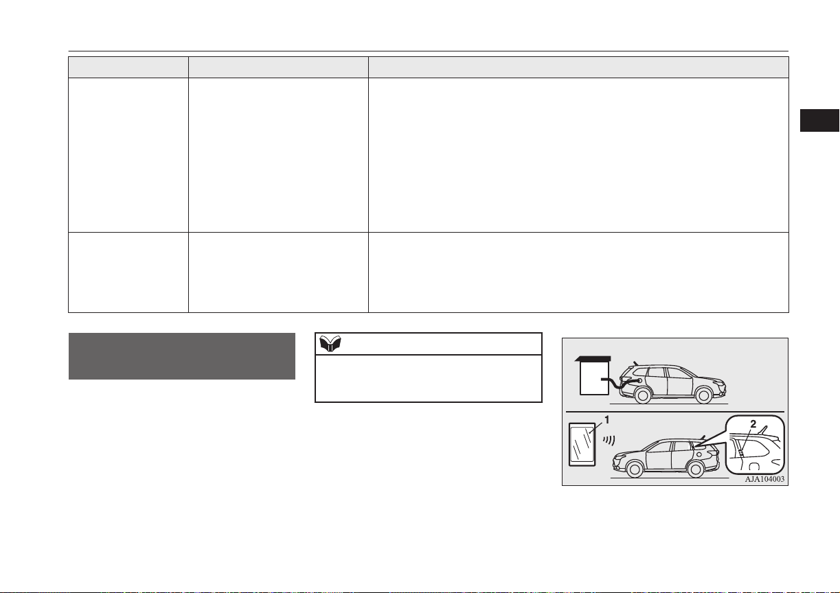
Symptom Possible cause Possible solution
The charging indicator
is continuously blinking even if the quick
charge connector is
not connected into the
quick charge port
when you start the
plug-in hybrid EV system after quick charging.
Plug-in Hybrid EV
System does not start
after quick charging.
Quick charging has not finished
normally.
The vehicle has a malfunction. There is a possibility that the vehicle has a malfunction. After turning the operation
Perform quick charging again and finish it normally or contact a MITSUBISHI
MOTORS Authorized Service Point.
mode of the power switch to “ON” and putting the select position to “N”, ask the
support of the fellow passenger or people nearby to move the vehicle by pushing it
into safety.
After moving, contact a MITSUBISHI MOTORS Authorized Service Point.
MITSUBISHI Remote Control*
E08304200084
The MITSUBISHI Remote Control allows to
operate the vehicle within the communication
range of the wireless LAN device (which
conforms to IEEE 802.11b and supports iOS
or Android). The following operations are
available.
NOTE
The communication distance differs depend-
l
ing on the wireless LAN device, due to this
the communication may go down.
MITSUBISHI Remote Control*
3
OGGE16E1
1- Wireless LAN device
2- Antenna
Charging
3-23
Page 56

MITSUBISHI Remote Control*
Charging timer
l
If you specify the charge start and/or
stop time with the normal charge cable
connected, charging is started and/or
3
stopped at that time.
Remote Climate Control
l
By setting the remote climate control to
operate at a predetermined time, cabin
comfort can be improved or visibility
NOTE
If you want to cancel the charging timer in
l
cases of the battery exhaustion or loss of a
wireless LAN device, you can temporary
cancelled the charging timer by pressing the
keyless operation key of the switch (A)
twice within 2 seconds. When the charging
timer is cancelled, the hazard warning lamps
will blink 4 times.
Devices that support wireless LAN are required to communicate with the vehicle using
the MITSUBISHI Remote Control. Also, an
SSID* (A) and password (B) are required to
connect a wireless LAN device to the vehicle. The SSID and password come with the
key at the time of your purchase of the vehicle.
can be ensured (defrosting/demisting)
before getting in the vehicle.
Customize (function setting change)
l
The function setting of the keyless operation system, security alarm, outside
rear-view mirror, operation mode of the
power switch, air conditioning, lamps
and windscreen wipers can be changed
by MITSUBISHI Remote Control.
NOTE
The electric heater is required to activate the
l
reservation functions of heater, defroster and
demister.
In a vehicle equipped with the MITSUBISHI
l
Multi-Communication System (MMCS), it
is possible to change the setting by means of
screen operations.
Refer to the separate owner’s manual for details.
For the operation method of the
MITSUBISHI Remote Control, please visit
MITSUBISHI Motors’ Website:
http://www.mitsubishi-motors.com/en/products/ outlander_phev/app/remote/index.html
If you need further information, please
l
contact a MITSUBISHI MOTORS Authorized Service Point.
3-24
Charging
*
An SSID is the identifier of an access point
for IEEE 802.11 series wireless LAN. It is
displayed on wireless LAN devices.
OGGE16E1
Page 57

MITSUBISHI Remote Control*
WARNING
Do not use the MITSUBISHI Remote
l
Control if children, persons in need of
care, pets, etc. are in the vehicle. Even if
the remote climate control is used, the
cabin may become hot or cold due to some
reasons such as automatic stop of the system. The cabin temperature may quickly
rise in sunshine, which poses a risk of heat
stroke and dehydration. In cold weather,
on the other hand, the cabin temperature
may quickly drop. Either of which could
lead to death in the worst case.
The cooling fan in the engine compart-
l
ment may operate automatically when
charging or when operating air conditioner. Do not bring your hand close to the
cooling fan during charging.
CAUTION
Do not use a car cover except for the
l
MITSUBISHI MOTORS GENUINE car
cover, when using the timer charging or the
remote climate control.
NOTE
Keep the following points in mind when us-
l
ing a wireless LAN device:
NOTE
Communication speed and range vary de-
•
pending on the wireless LAN devices and
the surrounding conditions (radio environment, obstacles, parking area environment, etc.).
Due to the characteristics of radio waves,
•
communication speed tends to decrease as
the communication distance increases.
Use your wireless LAN device at a short
distance from the vehicle for better response.
When a microwave oven or ISM (indus-
•
trial, scientific and medical) equipment is
being used, the communication speed and
range of wireless LAN devices may decrease. Use your wireless LAN device
away from these appliances and equipment.
If a wireless LAN device and Bluetooth
•
(registered trademark of Bluetooth SIG,
Inc.) are used simultaneously, the communication speed and range of each device may decrease. Use your wireless
LAN device away from Bluetooth devices.
Wireless LAN devices may not communi-
l
cate with the vehicle, or may not operate
normally or stably in the following environment or situations. Check that the device can
communicate with your vehicle before use.
There is an obstruction such as a concrete
•
or metal wall between the vehicle and
wireless LAN device.
NOTE
The vehicle is surrounded by tall vehicles
•
in a parking lot.
There are facilities nearby that emit strong
•
radio waves, such as a TV tower, transformer substation, broadcasting station or
airport.
There is a communication device such as
•
a mobile phone or radio, or an electric device such as a personal computer near the
wireless LAN device.
The wireless LAN device is in contact
•
with or covered by a metal object.
The battery of the wireless LAN device
•
has run down.
The MITSUBISHI Remote Control cannot
l
be used under the following conditions:
The wireless LAN device is turned off.
•
The MITSUBISHI Remote Control appli-
•
cation software is not installed.
The MITSUBISHI Remote Control appli-
•
cation software is not running.
The wireless LAN device is not registered
•
on the vehicle or it is not connected to the
vehicle.
The wireless LAN device is out of the
•
communication range.
The wireless LAN device is connected to
•
other wireless LAN device.
The wireless LAN device has failed, or its
•
battery has run out.
3
OGGE16E1
Charging
3-25
Page 58

MITSUBISHI Remote Control*
NOTE
Some charging facilities have a timer func-
l
tion that turns the power on or off at a spe-
3
cific time of the day. When charging at a facility with a timer function, make sure that
the charging timer is set within the time period when the power in the charging facility is
on.
The auxiliary battery is automatically and
l
periodically charged using electrical power
stored in the drive battery.
While the remote climate control is operat-
l
ing or the charging, the cooling fan or air
conditioner compressor may start operating
and its sound may be heard. This is normal.
The remote climate control operates in its
l
own mode based on the mode selected on
the wireless LAN device, regardless of the
switch setting of the vehicle’s air conditioner.
Air conditioning performance may deterio-
l
rate or the remaining charge in the drive battery may decrease under the following conditions:
In extremely hot weather.
•
In hot sunshine.
•
In extremely cold weather.
•
If the remote climate control is started dur-
l
ing charging, the time until full charge may
extend or the charging rate may decrease.
When the remaining quantity of the drive
l
battery is decreased, the remote climate control does not operate or it may stop on the
way.
NOTE
When the auxiliary battery is removed, the
l
timer control of the MITSUBISHI Remote
Control is reset and each function of the
MITSUBISHI Remote Control can not be
used. Also the drive battery can not be
warmed up.
Communicate the wireless LAN device and
your vehicle again.
3-26
Charging
OGGE16E1
Page 59

Locking and unlocking
Keys.................................................................................................... 4-02
Key number tag...................................................................................4-03
Electronic immobilizer (Anti-theft starting system)........................... 4-03
Keyless entry system...........................................................................4-03
Keyless operation system....................................................................4-06
Doors...................................................................................................4-14
Central door locks............................................................................... 4-16
Dead Lock System*............................................................................ 4-16
“Child-protection” rear doors..............................................................4-18
Tailgate*..............................................................................................4-18
Electric tailgate*................................................................................. 4-20
Inside tailgate release..........................................................................4-27
Security alarm system*....................................................................... 4-27
Electric window control......................................................................4-34
Sunroof*..............................................................................................4-36
4
OGGE16E1
Page 60
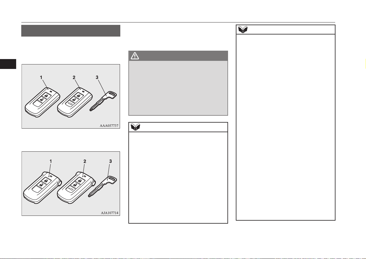
Keys
Keys
The key fits all locks.
without MITSUBISHI Remote Control
4
with MITSUBISHI Remote Control
1- Keyless operation key
E00300103817
2- Keyless operation key (with electric tail-
gate switch)
3- Emergency key
WARNING
When taking a key on flights, do not press
l
any switches on the key while on the
plane. If a switch is pressed on the plane,
the key emits electromagnetic waves,
which could adversely affect the plane’s
flight operation.
When carrying a key in a bag, be careful
that no switches on the key can be easily
pressed by mistake.
NOTE
The key is a precision electronic device with
l
a built-in signal transmitter. Please observe
the following in order to prevent a malfunction.
Do not leave in a place that is exposed to
•
direct sunlight, for example on the dashboard.
Do not disassemble or modify.
•
Do not excessively bend the key or sub-
•
ject it to strong impacts.
Do not expose to water.
•
Keep away from magnetic key rings.
•
Keep away from audio systems, personal
•
computers, TVs, and other equipment that
generates a magnetic field.
NOTE
Keep away from devices that emit strong
•
electromagnetic waves, such as cellular
phones, wireless devices and high frequency equipment (including medical devices).
Do not clean with ultrasonic cleaners or
•
similar equipment.
Do not leave the key where it may be ex-
•
posed to high temperature or high humidity.
The plug-in hybrid EV system is designed so
l
that it will not start if the ID code registered
in the immobilizer computer and the key’s
ID code do not match. Refer to the “Electronic immobilizer” section for details and
key usage.
[For vehicles equipped with the security
l
alarm system]
Pay attention to the following if the security
alarm is set to “Active”.
Refer to “Security alarm system” on page
4-27.
If the security alarm is in the system
•
armed mode, the alarm will sound if the
doors are opened after being unlocked
with the key, the inside lock knob or the
central door lock switch.
Even if the security alarm is set to “Ac-
•
tive”, the system preparation mode is not
entered if the keyless entry system or the
keyless operation function was not used to
lock the vehicle.
4-02
Locking and unlocking
OGGE16E1
Page 61

Key number tag
Key number tag
E00312700011
The key number is stamped on the tag as indicated in the illustration.
Make a record of the key number and store
the key and key number tag in separate places, so that you can order a key from your authorized MITSUBISHI MOTORS dealer in
the event the original keys are lost.
Electronic immobilizer (Anti-theft starting system)
E00300202996
The electronic immobilizer is designed to
significantly reduce the possibility of vehicle
theft. The purpose of the system is to immobilize the vehicle if an invalid start is attempted. A valid start attempt can only be achieved by using a key “registered” to the immobilizer system.
NOTE
If the plug-in hybrid EV system does not
l
start, we recommend you to contact your
MITSUBISHI MOTORS Authorized Service Point.
If you lose one of keyless operation keys,
l
contact your MITSUBISHI MOTORS Authorized Service Point as soon as possible.
To obtain a replacement or extra spare key,
take your vehicle and all remaining keys to
your MITSUBISHI MOTORS Authorized
Service Point. All the keys have to be re-registered in the immobilizer computer unit.
The immobilizer can register as follows.
Keyless operation key: up to 4 different
•
keys
CAUTION
Do not modify or add parts to the immobiliz-
l
er system. Doing so could cause the immobilizer to malfunction.
Keyless entry system
E00300304092
Press the remote control switch, and all doors
and the tailgate will be locked or unlocked as
desired. It is also possible to operate the outside rear-view mirrors.
OGGE16E1
1- LOCK switch
2- UNLOCK switch
3- Electric tailgate switch*
4- Indication lamp
5- Charging timer cancel switch*
To lock
Press the LOCK switch (1). All the doors and
the tailgate will be locked. The turn-signal
lamps will blink once when the doors and the
tailgate are locked.
Locking and unlocking
4-03
4
Page 62

Keyless entry system
To unlock
Press the UNLOCK switch (2). All the doors
and the tailgate will be unlocked. If the doors
and tailgate are unlocked when the front
room lamp switch is in the “DOOR” position
4
or the rear room lamp switch is in the middle
(•) position, the room lamp will illuminate for
approximately 15 seconds and the turn-signal
lamps will blink twice.
The position and tail lamps can also be set to
turn on for about 30 seconds. Refer to “Welcome light” on page 6-50.
NOTE
For the operation of the Electric tailgate
l
switch (3), refer to “Electric tailgate” on
page 4-20.
For the operation of the Charging timer can-
l
cel switch (5), refer to “MITSUBISHI Remote Control” on page 3-23 .
The door and tailgate unlock function can be
l
set so that only the driver’s door unlocks
when the UNLOCK switch (2) is pressed
once.
If the door and tailgate unlock function is set
to work as described above, all the doors and
the tailgate unlock when the UNLOCK
switch is pressed two times in succession.
Refer to “Setting of door and tailgate unlock
function” on page 4-05.
4-04
Locking and unlocking
NOTE
If the UNLOCK switch (2) is pressed and no
l
door or tailgate is opened within approximately 30 seconds, relocking will automatically occur.
If either of the following problems occurs,
l
the battery may be exhausted.
The remote control switch is operated at
•
the correct distance from the vehicle, but
the doors and tailgate are not locked/
unlocked in response.
The indication lamp (4) is dim or does not
•
come on.
For further information, please consult
your MITSUBISHI MOTORS Authorized
Service Point.
If you replace the battery yourself, refer to
“Procedure for replacing the remote control switch battery” on page 4-05.
It is possible to modify functions as follows:
l
For further information, please contact your
MITSUBISHI MOTORS Authorized Service Point.
On vehicles equipped with MITSUBISHI
Multi-Communication System (MMCS),
screen operations can be used to make the
adjustment. Refer to the separate owner’s
manual for details.
The time for automatic relocking can be
•
changed.
OGGE16E1
NOTE
The confirmation function (flashing of the
•
turn-signal lamps) can be set to operate
only when the doors and backdoor are
locked or only when the doors and backdoor are unlocked.
The confirmation function (this indicates
•
locking or unlocking of the doors and tailgate with the blink of the turn-signal
lamps) can be deactivated.
The number of times the turn-signal
•
lamps are flashed by the confirmation
function can be changed.
Operation of the outside rearview mirrors (Vehicles equipped with mirror retractor
switch)
E00310801477
To fold
Within 30 seconds of locking the doors and
tailgate using the LOCK switch (1), press the
LOCK switch twice rapidly to fold the outside rear-view mirrors.
To extend
Within 30 seconds of unlocking the doors
and tailgate using the UNLOCK switch (2),
press the UNLOCK switch twice rapidly to
return the outside rear-view mirrors to their
extended positions.
Page 63

Keyless entry system
The outside rear-view mirrors are not initially
set to work as described above. If you want
them to work as described above, you need to
set them so that they do not retract/extend
when the doors and tailgate are locked/
unlocked using the keyless entry system or
keyless operation function.
Refer to “Outside rear-view mirrors” on page
7-07.
For details, please consult a MITSUBISHI
MOTORS Authorized Service Point.
In a vehicle equipped with the MITSUBISHI
Multi-Communication System (MMCS), it is
possible to change the setting by means of
screen operations.
Refer to the separate owner’s manual for details.
NOTE
The outside rear-view mirrors automatically
l
retract when all the doors and tailgate are
locked using the keyless operation function.
Refer to “Outside rear-view mirrors” on
page 7-07.
The keyless entry system does not operate
l
when the door or tailgate is open.
NOTE
The remote control switch will operate with-
l
in approximately 4 m from the vehicle.
However, the operating range of the remote
control switch may change if the vehicle is
located near a power station, or radio/TV
broadcasting station.
If your remote control switch is lost or dam-
l
aged, please contact your MITSUBISHI
MOTORS Authorized Service Point for a replacement remote control switch.
If you wish to add a remote control switch,
l
we recommend you to contact your
MITSUBISHI MOTORS Authorized Service Point.
The below remote control switches are available for your vehicle.
Keyless operation key: up to 4 remote
•
control switches
Setting of door and tailgate unlock function
The door and tailgate unlock function can be
set to the following two conditions.
Each time the door and tailgate unlock function is set, a chime will sound to tell you the
condition of the door and tailgate unlock
function.
Number of chimes Condition
One chime All doors and the
tailgate unlock
E00310301296
Number of chimes Condition
Two chimes Driver’s door unlock
only
1. Put the operation mode in OFF.
2. Place the combination headlamps and
dipper switch in the “OFF” position, and
leave the driver’s door open.
3. Press the LOCK switch (1) for 4 to 10
seconds and press the UNLOCK switch
(2) during this time.
4. Release in sequence the LOCK and UNLOCK switches within 10 seconds of
pressing the LOCK switch in step 3.
NOTE
On vehicles equipped with MITSUBISHI
l
Multi-Communication System (MMCS),
screen operations can be used to make the
adjustment. Refer to the separate owner’s
manual for details.
Procedure for replacing the remote control switch battery
Before replacing the battery, remove static
electricity from your body by touching a metal grounded object.
E00309501243
4
OGGE16E1
Locking and unlocking
4-05
Page 64
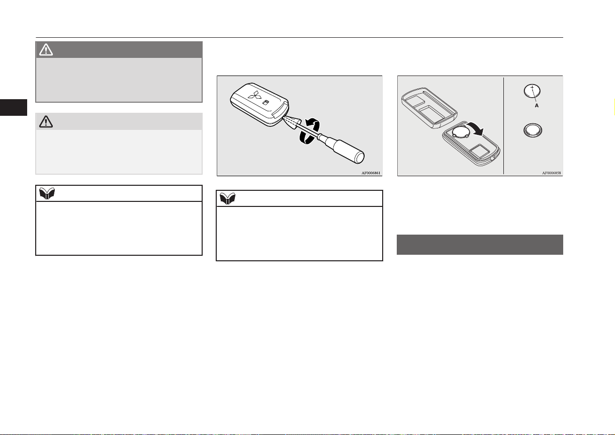
+ side
- side
Coin type battery
CR2032
Keyless operation system
WARNING
Danger of explosion if battery is incor-
l
rectly replaced.
Replace only with the same battery or an
equivalent type.
4
CAUTION
When the remote control switch case is
l
opened, be careful to keep water, dust, etc.
out. Also, do not touch the internal components.
NOTE
You may purchase a replacement battery at
l
an electric appliance store.
A MITSUBISHI MOTORS Authorized
l
Service Point can replace the battery for you
if you prefer.
1. With the MITSUBISHI mark facing
you, insert the cloth covered tip of a
straight blade (or minus) screwdriver in-
to the notch in the remote control switch
case and use it to open the case.
NOTE
Be sure to perform the procedure with the
l
MITSUBISHI mark facing you. If the
MITSUBISHI mark is not facing you when
you open the remote control switch case, the
transmitter may come out.
2. Remove the old battery.
3. Install a new battery with the + side (A)
up.
4. Close the case firmly.
5. Check the keyless operation function to
see that it works.
Keyless operation system
E00305601738
The keyless operation system allows you to
lock and unlock the doors and tailgate and
start the engine simply by carrying the keyless operation key with you.
The keyless operation key can also be used as
the keyless entry system remote control
switch.
Refer to “Keyless entry system” on page
4-03.
4-06
Locking and unlocking
OGGE16E1
Page 65

Keyless operation system
The driver should always carry the keyless
operation key. This key is necessary for locking and unlocking the doors and tailgate,
starting the engine and otherwise operating
the vehicle, so before locking and leaving the
vehicle, be sure to check that you have the
keyless operation key.
WARNING
People with implantable cardiac pace-
l
makers or implantable cardiovascular-defibrillators should not go near the exterior
transmitters (A) or the interior transmitters (B). The radio waves used by the keyless operation system could adversely affect implantable cardiac pacemakers or
implantable cardiovascular-defibrillators.
WARNING
When using electro-medical devices other
l
than implantable cardiac pacemakers or
implantable cardiovascular-defibrillators,
contact the electromedical device manufacturer ahead of time to determine the
affects of radio waves on the devices. Electromedical device operations could be adversely effected by radio waves.
You can limit the possible operations of
the keyless operation system in the following ways. (The keyless operation
system can be used as a keyless entry
system.) Please consult a MITSUBISHI
MOTORS Authorized Service Point.
• You can limit operations to locking
and unlocking the doors and tailgate.
• You can limit operations to starting
the engine.
• The keyless operation system can be
disabled.
When keyless operation system operations are modified, the operating transmitters are as follows.
• Only locking and unlocking doors or
tailgate: exterior transmitter and interior transmitters
• Only starting the engine: interior
transmitter
NOTE
The keyless operation key uses an ultra-
l
weak electromagnetic wave. In the following
cases, the keyless operation system may not
operate properly or may be unstable.
When there is equipment nearby that
•
emits strong radio waves, such as: a power station, a radio/TV broadcasting station
or an airport.
The keyless operation system is carried
•
together with a communications device
such as a cellular phone or radio set, or
with an electronic device such as a personal computer.
The keyless operation key is touching or
•
covered by a metal object.
A keyless entry system is being used
•
nearby.
When the keyless operation key battery is
•
worn out.
When the keyless operation key is placed
•
in an area with strong radio waves or
noise.
In such cases, use the emergency key.
Refer to “To operate without using the
keyless operation function” on page
4-14.
4
OGGE16E1
Locking and unlocking
4-07
Page 66
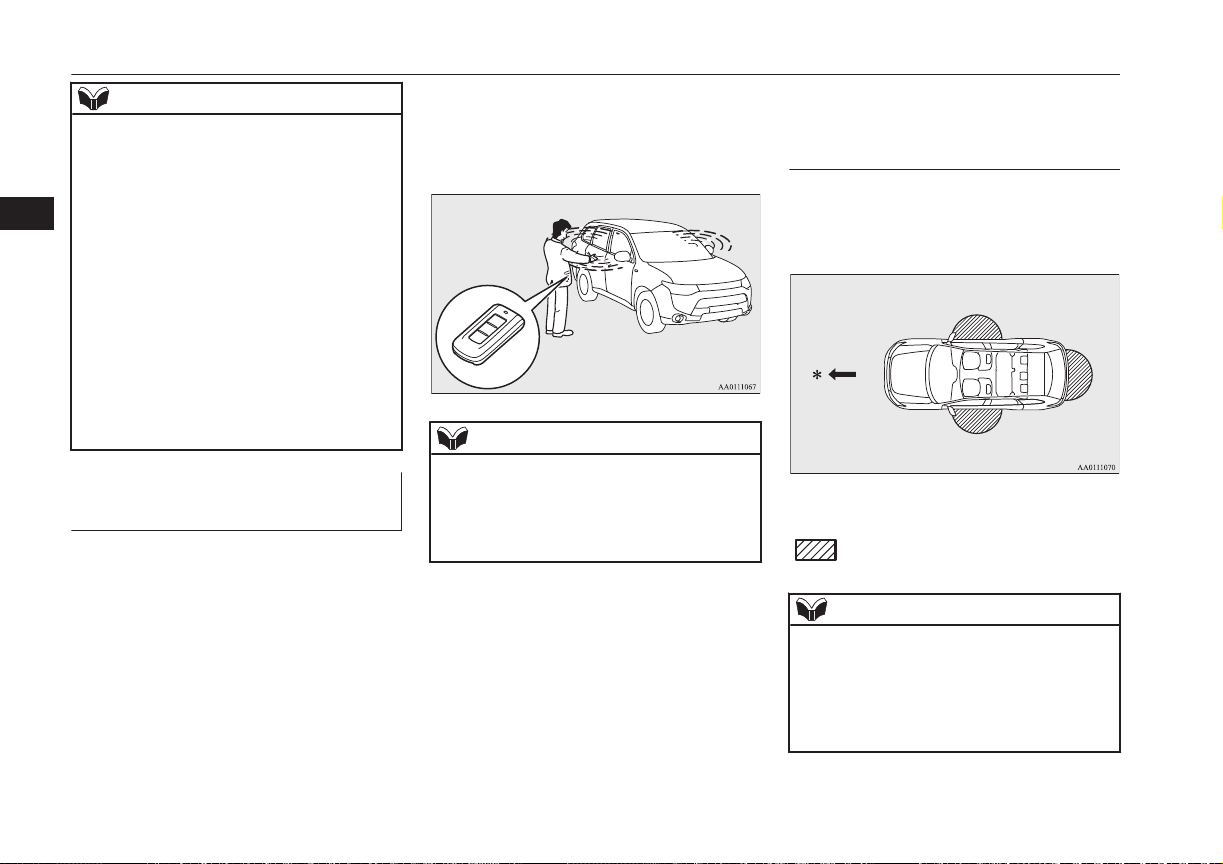
Keyless operation system
NOTE
Because the keyless operation key receives
l
signals in order to communicate with the
transmitters in the vehicle, the battery continually wears down regardless of keyless
4
operation key use. The battery life is 1 to 3
years, depending on usage conditions. When
the battery wears out, replace the battery according to the description in this manual or
have it replaced at your MITSUBISHI
MOTORS Authorized Service Point.
Refer to “Procedure for replacing the remote
control switch battery” on page 4-05.
Because the keyless operation key continual-
l
ly receives signals, strong radio wave reception could affect battery wear. Do not leave
the key near a TV, personal computer, or
other electronic device.
Operating range of the keyless operation system
If you are carrying the keyless operation key,
enter the operating range of the keyless operation system, and press the driver’s or front
passenger’s door lock/unlock switch, the tailgate LOCK switch or the tailgate open
switch, the ID code for your key is verified.
E00305701641
You can lock and unlock the doors and tailgate and start the engine only if the ID codes
of your keyless operation key and the vehicle
match.
NOTE
If the keyless operation key battery is wear-
l
ing out or there are strong electromagnetic
waves or noise present, the operating range
may become smaller and operation may become unstable.
Operating range for locking and unlocking the doors and tailgate
The operating range is about 70 cm from the
driver’s door handle, front passenger’s door
handle, and tailgate handle.
*: Forward direction
Operating range
:
E00306201601
NOTE
Locking and unlocking operate only when
l
you press a door or tailgate switch that detects the keyless operation key.
Operation may not be possible if you are too
l
close to the front door, door window, or tailgate.
4-08
Locking and unlocking
OGGE16E1
Page 67
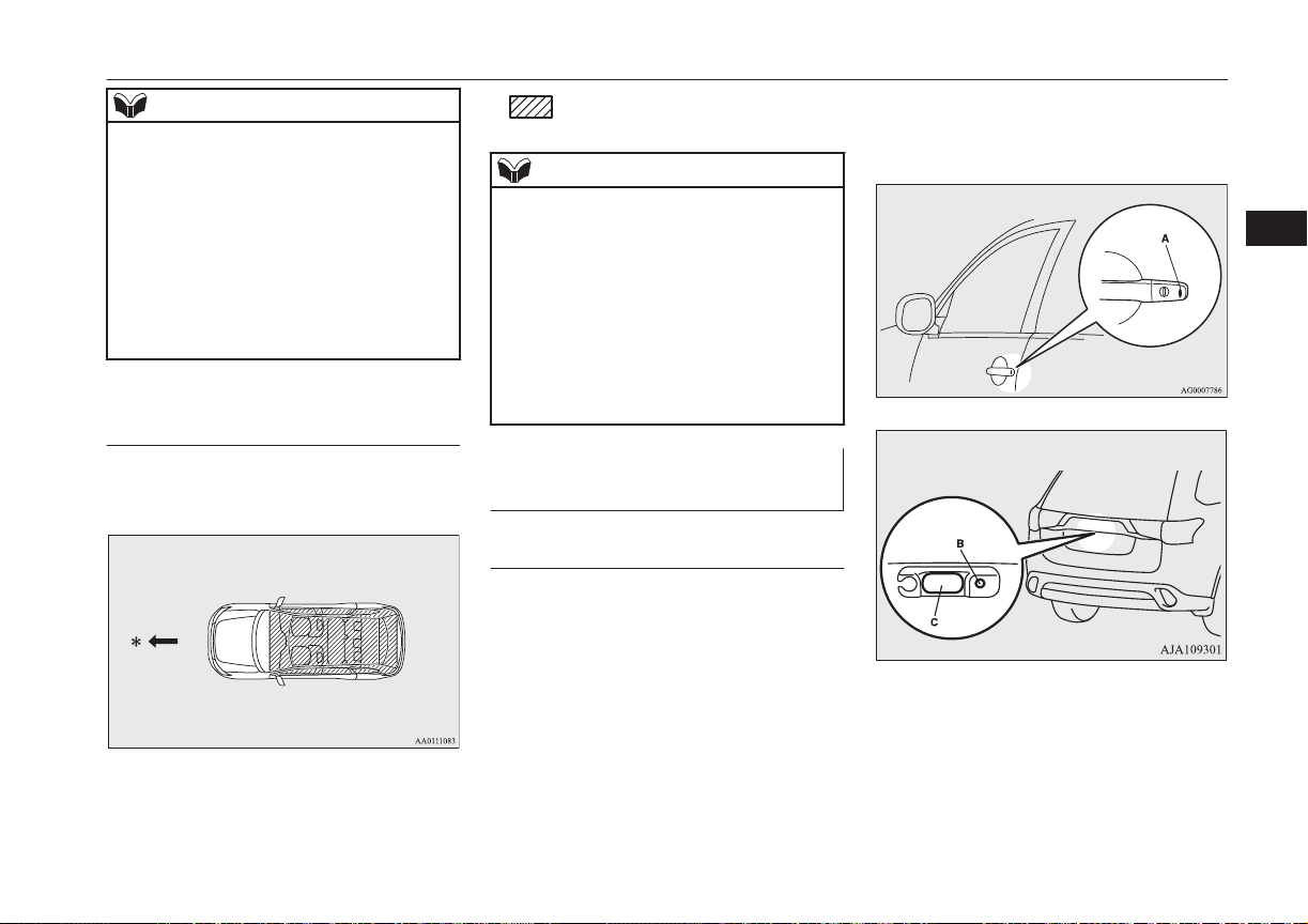
Driver’s or front passenger’s door
lock/unlock switches
Tailgate switches
Keyless operation system
NOTE
Even if the keyless operation key is within
l
70 cm of the driver’s door handle, front passenger’s door handle, or tailgate handle, if
the key is near to the ground or high up, the
system may not operate.
If the keyless operation key is within the op-
l
erating range, even someone not carrying the
key can lock and unlock the doors and tailgate by pressing the driver’s or front passenger’s door lock/unlock switch, the tailgate
lock switch or the tailgate open switch.
Operating range for starting the engine
The operating range is the interior of the vehicle.
E00306301370
Operating range
:
NOTE
Even if it is within the operating range, if the
l
keyless operation key is in a small item
holder such as the glove box, on top of the
instrument panel, door pocket or in the luggage area, it may be impossible to start the
engine.
If a keyless operation key is too close to the
l
door or door window, it may be possible to
start the engine or change the operation
mode even when the key is outside the vehicles.
To operate using the keyless operation function
E00305802333
Locking the doors and tailgate
When you are carrying the keyless operation
key, if you press the driver’s or front passenger’s door lock/unlock switch (A), or the tailgate LOCK switch (B) within the operating
range, the doors and the tailgate are locked.
The turn-signal lamps will blink once.
Also refer to “Locking and unlocking: Doors,
Central door locks, Tailgate” on pages 4-14,
4-16 and 4-18.
4
*: Forward direction
OGGE16E1
Locking and unlocking
4-09
Page 68

Driver’s and front passenger’s door lock/unlock switches
Tailgate switches
Keyless operation system
NOTE
For vehicles equipped with the mirror retrac-
l
tor switch, the outside rear-view mirrors automatically retract when all the doors and
tailgate are locked using the keyless opera-
4
tion function.
Refer to “Outside rear-view mirrors” on
page 7-07.
The keyless operation function does not op-
l
erate under the following conditions:
The keyless operation key is inside the
•
vehicle.
A door or the tailgate is open or ajar.
•
The tailgate open switch (C) can be used to
l
check that the vehicle is locked properly.
Press the tailgate open switch within about 3
seconds of locking the vehicle. If you wait
longer than 3 seconds and press the tailgate
open switch, the doors and tailgate will be
unlocked.
The time allowed for checking that the vehi-
l
cle is locked can be adjusted. For further information, please contact your
MITSUBISHI MOTORS Authorized Service Point.
On vehicles equipped with MITSUBISHI
Multi-Communication System (MMCS),
screen operations can be used to make the
adjustment. Refer to the separate owner’s
manual for details.
Unlocking the doors and tailgate
When you are carrying the keyless operation
key, if you press the driver’s or front passenger’s door lock/unlock switch (A), or the tailgate open switch (B) within the operating
range, all the doors and the tailgate are unlocked.
If the front room lamp switch is in the
“DOOR” position or the rear room lamp
switch is in the middle (•) position at this
time, the room lamp will turn on for 15 seconds. The turn-signal lamps will blink twice.
If the driver’s or front passenger’s door lock/
unlock switch is pressed and any of the doors
or tailgate is not opened within approximately 30 seconds, relocking will automatically
occur.
Also refer to “Locking and unlocking: Doors,
Central door locks, Tailgate” on pages 4-14,
4-16 and 4-18.
NOTE
For vehicles equipped with the mirror retrac-
l
tor switch, the outside rear-view mirrors automatically extend when all the doors and
tailgate are unlocked using the keyless operation function.
Refer to “Outside rear-view mirrors” on
page 7-07.
The keyless operation function can be set so
l
that only the driver’s door unlocks when the
driver’s door lock/unlock switch is pressed.
If the keyless operation function is set to
work as described above, all the doors and
the tailgate unlock when the driver’s door
lock/unlock switch is pressed two times in
succession.
Refer to “Setting of door and tailgate unlock
function” on page 4-05.
The keyless operation function does not op-
l
erate under the following conditions:
A door or the tailgate is open or ajar.
•
4-10
Locking and unlocking
OGGE16E1
Page 69

Keyless operation system
NOTE
In order to make it possible to check that the
l
doors and tailgate are locked, you cannot unlock them by using the tailgate open switch
for 3 seconds after locking them.
The time allowed for checking that the vehi-
l
cle is locked can be adjusted. For further information, please contact your
MITSUBISHI MOTORS dealer.
On vehicles equipped with MITSUBISHI
Multi-Communication System (MMCS),
screen operations can be used to make the
adjustment. Refer to the separate owner’s
manual for details.
The time between unlocking and automatic
l
locking can be adjusted. Please consult a
MITSUBISHI MOTORS Authorized Service Point.
On vehicles equipped with MITSUBISHI
Multi-Communication System (MMCS),
screen operations can be used to make the
adjustment. Refer to the separate owner’s
manual for details.
Operation confirmation when locking and unlocking
Operation can be confirmed as shown below.
However, the room lamp will only illuminate
if the front room lamp switch is in the
“DOOR” position or the rear room lamp
switch is in the middle (•) position.
When locking: The turn-signal
lamps will blink
once.
When unlocking: The room lamp will
illuminate for approximately 15 seconds, the turn-signal
lamps will blink
twice.
NOTE
Functions can be modified as stated below.
l
For further information, please contact your
MITSUBISHI MOTORS Authorized Service Point.
On vehicles equipped with MITSUBISHI
Multi-Communication System (MMCS),
screen operations can be used to make the
adjustment. Refer to the separate owner’s
manual for details.
Set the confirmation function (blinking of
•
the turn-signal lamps) to operate only
when the vehicle is locked or only when
the vehicle is unlocked.
Disable the operation confirmation func-
•
tion (blinking of the turn-signal lamps).
Change the number of blinks for the oper-
•
ation confirmation function (blinks of the
turn-signal lamps).
4
OGGE16E1
Locking and unlocking
4-11
Page 70

Keyless operation system
Warning activation
In order to prevent vehicle theft or the accidental operation of the keyless operation system, the buzzer and the display on the information screen
in the multi-information display are used to alert the driver.
If a warning is activated, always check the vehicle and the keyless operation key. The warning is also displayed if there is a fault in the keyless
operation system.
4
Item Display Buzzer Note (Solution)
Detection of failure Inner buzzer sounds
once
There is a fault in the keyless operation system.
E00305901715
Fall of battery voltage Inner buzzer sounds
once
Key not detected Inner buzzer sounds
once
Keyless operation key
reminder
4-12
Locking and unlocking
Inner buzzer sounds
about 1 minute
Outer buzzer sounds
about 3 seconds intermittently
OGGE16E1
The battery starts to run out, the warning is activated. (The
warning is not activated if the battery is completely dead.)
When the engine switch is turned to the ACC or ON from OFF
or when the engine is started, the warning is activated, if any of
the following conditions is occurred.
Carrying another keyless operation key with a different
l
code, or the keyless operation key could be outside the operating range.
The battery of the keyless operation key is dead.
l
Communication is blocked by electric wave environment.
l
If the operation mode is in OFF and the driver’s door is opened
with the keyless operation key in the key slot, a warning is issued and the outer buzzer sounds for about 3 seconds and the inner buzzer sounds for about 1 minute to remind you to remove
the key. If the key removed from key slot, the buzzer is stopped.
Page 71

Item Display Buzzer Note (Solution)
Keyless operation key
take-out monitoring system
Key lock-in prevention
system
Inner buzzer sounds
once
Outer buzzer sounds intermittently
Inner buzzer sounds
once
Outer buzzer sounds
about 3 seconds intermittently
Keyless operation system
When the vehicle is parked with the operation mode in any
l
mode other than OFF, if you close the door after opening
any of the doors and taking the keyless operation key out of
the vehicle, a warning is issued until the key is detected in
the vehicle.
If you take the keyless operation key out of the vehicle
l
through a window without opening a door, the keyless operation key take-out monitoring system does not operate.
It is possible to change the setting to make the keyless oper-
l
ation key take-out monitoring system operate if you take
the keyless operation key out from the vehicle through a
window without opening a door.
For further information, please contact a MITSUBISHI
MOTORS Authorized Service Point.
Even if you have the keyless operation key within the en-
l
gine start operating range, if the keyless operation key and
vehicle ID codes cannot be matched, for example due to the
ambient environment or electromagnetic conditions, the
warning may be activated.
When the operation mode is in OFF, if you close all the
l
doors and the tailgate with the keyless operation key left in
the vehicle and you try to lock the doors and tailgate by
pressing the driver’s or front passenger’s door lock/unlock
switch, or the tailgate LOCK switch, a warning is issued
and you cannot lock the doors and tailgate.
Make sure you have the keyless operation key with you be-
l
fore locking the doors. Even if you leave the keyless operation key inside the vehicle, it is possible that the doors will
lock depending on the surrounding environment and wireless signal conditions.
4
OGGE16E1
Locking and unlocking
4-13
Page 72
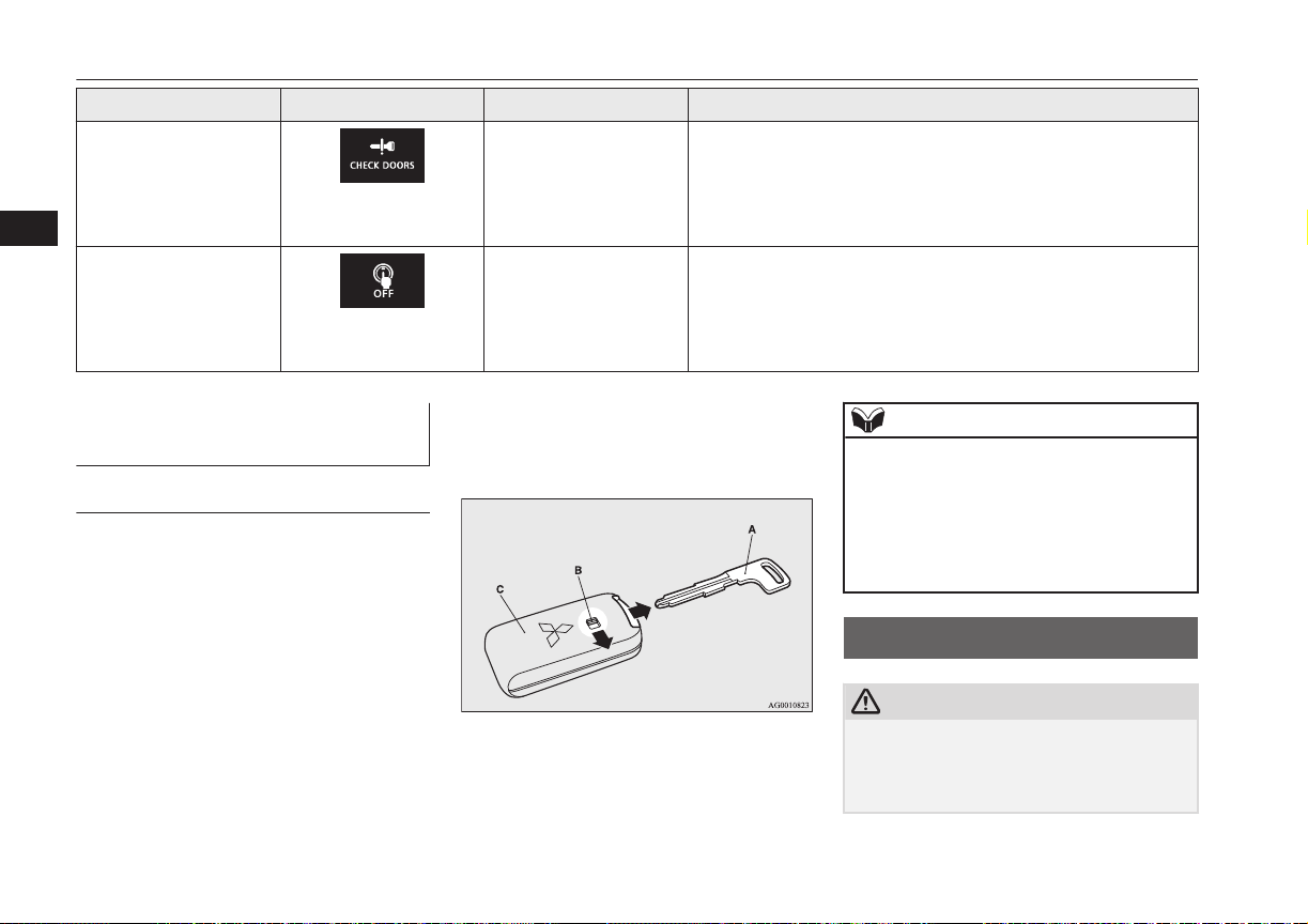
Doors
Item Display Buzzer Note (Solution)
Door ajar prevention
system
4
Operation mode OFF reminder system
To operate without using the keyless operation function
Emergency key
The emergency key is built into the keyless
operation key. If the keyless operation function cannot be used, for example because the
keyless operation key battery has worn out or
the vehicle battery is flat, you can lock and
unlock the driver’s door and start the engine
with the emergency key.
To use the emergency key (A), unlock the
lock knob (B) and remove it from the keyless
operation key (C).
E00306000019
E00307201464
Inner buzzer sounds
once
Outer buzzer sounds
about 3 seconds intermittently
Inner buzzer sounds
once
Outer buzzer sounds
about 3 seconds intermittently
Refer to “Doors” on page 4-14, or “If the
keyless operation key is not operating properly” on page 7-12.
When the operation mode in OFF, if you try to lock the doors
and tailgate by pressing the driver’s or front passenger’s door
lock/unlock switch, or the tailgate LOCK switch with one of the
doors or the tailgate not completely closed, a warning is issued
and you cannot lock the doors and tailgate.
When the operation mode is in any mode other than OFF, if you
close all the doors and the tailgate then try to lock the doors and
tailgate by pressing the driver’s or front passenger’s door lock/
unlock switch, or the tailgate LOCK switch, a warning is issued
and you cannot lock the doors and tailgate.
NOTE
Only use the emergency key for emergen-
l
cies. If the keyless operation key battery
wears out, replace it as quickly as possible
so that you can use the keyless operation
key.
After using the emergency key, always re-
l
turn it into the keyless operation key.
Doors
CAUTION
Make sure the doors are closed: driving with
l
doors not completely closed is dangerous.
Never leave children in the vehicle unatten-
l
ded.
E00300402291
4-14
Locking and unlocking
OGGE16E1
Page 73

Doors
CAUTION
Be careful not to lock the doors while the
l
key is inside the vehicle.
NOTE
To prevent the key from being locked inside
l
the vehicle, neither the lock knob on the
driver’s door nor the key can be used to lock
the driver’s door when it is open.
To lock or unlock with the key
1- Lock
2- Unlock
NOTE
When locking or unlocking with the key, on-
l
ly the driver’s door will be locked or unlocked.
To lock or unlock all doors and the tailgate,
use the central door lock switch, the keyless
entry system or the keyless operation function.
Refer to “Central door locks” on page 4-16,
“Keyless entry system” on page 4-03, and
“To operate using the keyless operation
function” on page 4-09.
If the vehicle is equipped with the keyless
l
operation system, the driver’s door can be
locked or unlocked with the emergency key.
Refer to “Emergency key” on page 4-14.
To lock or unlock from inside the vehicle
Pull the inside door handle towards you to
open the door.
NOTE
The driver’s door can be opened without us-
l
ing the lock knob by pulling on the inside
door handle.
To lock without using the key
Front passenger’s door, Rear door
Set the inside lock knob (1) to the locked position, and close the door (2).
4
1- Lock
2- Unlock
OGGE16E1
Locking and unlocking
4-15
Page 74

LHD RHD
Central door locks
Central door locks
NOTE
Repeated continuous operation between lock
l
4
and unlock could activate the central door
locking systems built-in protection circuit
and prevent the system from operating. If
this occurs, wait approximately 1 minute before operating the central door lock switch.
When the driver’s door is open, the central
l
door lock switch cannot be used to lock it.
E00300801937
To lock and unlock the doors and tailgate
Using the central door lock switch
Using the central door lock switch on the
driver’s door locks or unlocks all doors and
the tailgate.
1- Lock
2- Unlock
To unlock the doors and tailgate
E00311301336
You can select the function to unlock the
doors and tailgate using the engine switch.
This function is not activated when the vehicle is shipped from the factory. To activate or
deactivate this function, please contact a
MITSUBISHI MOTORS Authorized Service
Point.
Using the power switch
All doors and the tailgate will unlock whenever the operation mode is put in OFF.
Dead Lock System*
E00305100198
The Dead Lock System helps prevent theft.
When the keyless entry system or the keyless
operation system has been used to lock all of
the doors and the tailgate, the Dead Lock
System makes it impossible to unlock the
doors using the inside lock knobs.
CAUTION
Do not set the Dead Lock System when
l
someone is inside the vehicle. With the Dead
Lock System set, it is not possible to unlock
the doors using the inside lock knobs. If you
erroneously set the Dead Lock System, unlock the doors using the UNLOCK switch
on the remote control switch or using the
keyless operation function.
4-16
Locking and unlocking
OGGE16E1
Page 75

Driver’s and front passenger’s door lock/unlock
switches*
Tailgate switches*
Dead Lock System*
Setting the system
1. Put the operation mode in OFF.
2. Get out of the vehicle. Close all of the
doors and the tailgate.
3. Press the LOCK switch (A) on the remote control switch, the driver’s or front
passenger’s door lock/unlock switch (C),
or the tailgate LOCK switch (D) to lock
all of the doors and the tailgate. The
turn-signal lamps will blink once.
4. Press the switch again within 2 seconds.
The turn-signal lamps will blink three
times to show that the Dead Lock System has been set.
E00305201239
NOTE
Pressing the LOCK switch (A) on the re-
l
mote control switch once while the Dead
Lock System is set causes the turn-signal
lamps to blink three times, so it is possible to
confirm that the Dead Lock System is set.
Cancelling the system
When the following operation is performed,
the doors and tailgate will unlock and the
Dead Lock System will be simultaneously
cancelled.
The UNLOCK switch (B) on the remote
l
control switch is pressed.
The driver’s or front passenger’s door
l
lock/unlock switch (C) is pressed while
you are carrying the keyless operation
key.
The tailgate open switch (E) is pressed.
l
E00305300233
NOTE
If neither a door nor the tailgate is opened
l
within 30 seconds of unlocking (except using the tailgate open switch), the doors and
tailgate are automatically relocked and the
Dead Lock System is simultaneously set
again.
Even when it is not possible to use the key-
l
less entry system or keyless operation function to unlock the doors, it is possible to use
the key to unlock the driver’s door. When
the key is used to unlock the driver’s door,
the Dead Lock System is cancelled for only
the driver’s door. If you wish to subsequently unlock all other doors, turn the ignition
switch to the “ON” or “ACC” position, or
put the operation mode in on or ACC.
4
OGGE16E1
Locking and unlocking
4-17
Page 76

“Child-protection” rear doors
NOTE
It is possible to adjust the time between
l
pressing the UNLOCK switch (B) on the remote control switch or the driver’s or front
passenger’s door lock/unlock switch (C) and
4
automatic locking. For details, please contact a MITSUBISHI MOTORS Authorized
Service Point.
On vehicles equipped with MITSUBISHI
Multi-Communication System (MMCS),
screen operations can be used to make the
adjustment. Refer to the separate owner’s
manual for details.
It is possible to lock the doors and tailgate
l
and set the Dead Lock System at the same
time with a single push of the LOCK switch
(A) on the remote control switch, the driver’s or front passenger’s door lock/unlock
switch (C), or the tailgate lock switch (D).
For details, please contact a MITSUBISHI
MOTORS Authorized Service Point.
Testing the system
Open all of the door windows, then set the
Dead Lock System.
(Refer to “Setting the system” on page 4-17.)
After setting the Dead Lock System, reach
into the vehicle through a window and confirm that you cannot unlock the doors using
the lock knobs.
E00305400159
NOTE
If you need advice on how to set the Dead
l
Lock System, please contact a MITSUBISHI
MOTORS Authorized Service Point.
“Child-protection” rear
doors
E00300901042
1- Lock
2- Unlock
Child protection helps prevent the rear doors
from being opened accidentally from the inside.
If the lever is set to the locked position, the
rear door cannot be opened using the inside
handle, but only with the outside handle.
If the lever is set to the “Unlock” position,
the child protection mechanism does not
function.
CAUTION
When driving with a child in the rear seat,
l
please use the child protection to prevent accidental door opening which may cause an
accident.
Tailgate*
WARNING
It is dangerous to drive with the tailgate
l
open, since carbon monoxide (CO) gas
can enter the cabin.
You cannot see or smell CO. It can cause
unconsciousness and even death.
When opening and closing the tailgate,
l
make sure that there are no people nearby and be careful not to hit your head or
pinch your hands, neck, etc.
When there is a build up of snow or ice, it
l
should be removed before opening the
tailgate. If you open the tailgate without
removing it, there is a possibility that the
tailgate may close suddenly due to the
weight of that snow or ice.
E00301402517
4-18
Locking and unlocking
OGGE16E1
Page 77
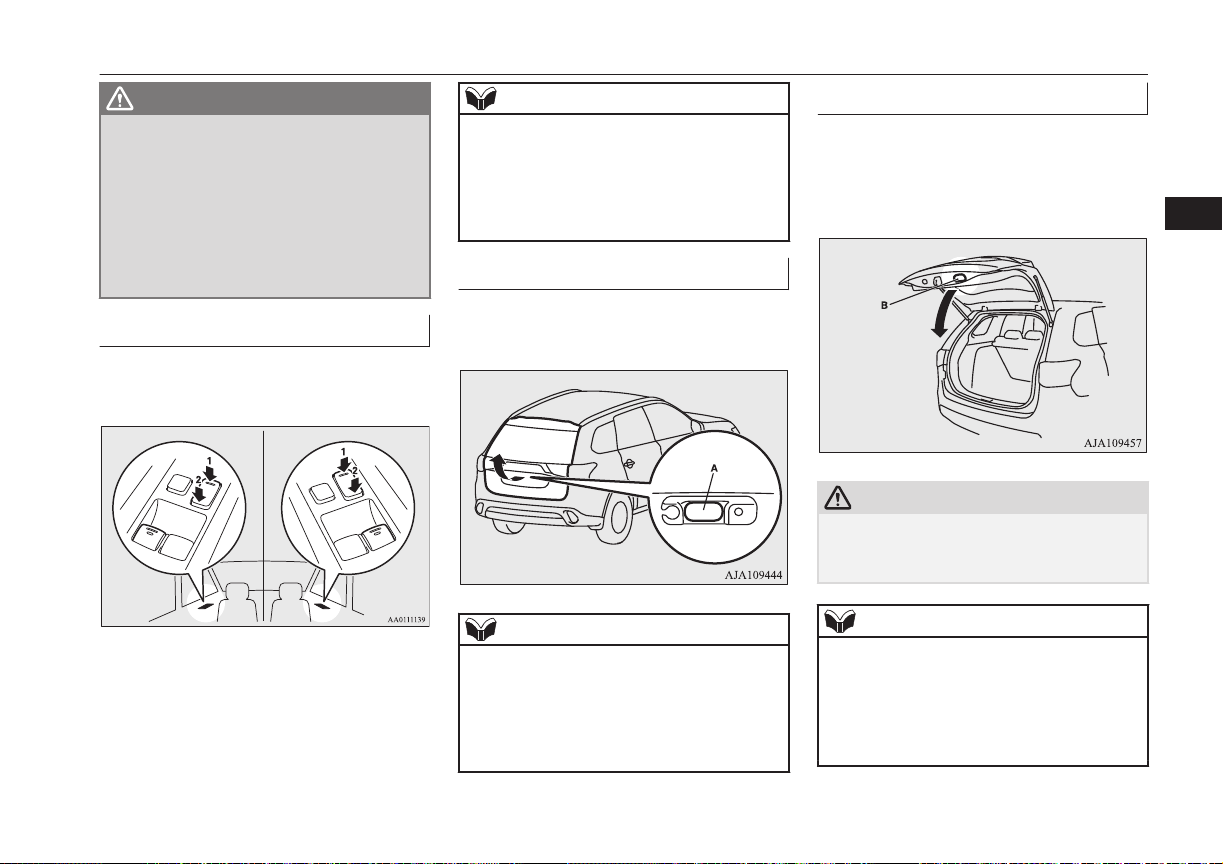
LHD RHD
Tailgate*
WARNING
When you open the tailgate make sure
l
that the tailgate is opened fully and remains fully open. If you only open the tailgate halfway there is a risk that the tailgate may drop and slam shut. If you open
the tailgate whilst your vehicle is parked
on an incline it is more difficult to do so
than on the flat and also it may drop and
slam shut.
To lock/unlock
The tailgate can be locked or unlocked by using the central door lock switch (driver side).
1- Lock
2- Unlock
NOTE
Repeated continuous operating between lock
l
and unlock could cause the central door
locks’ built-in protection circuit to prevent
the system from operating. If this occurs,
wait approximately 1 minute before operating the central door lock switch.
To open
After unlocking the tailgate, push the tailgate
open switch (A) and pull up the tailgate.
NOTE
The tailgate cannot be opened when the bat-
l
tery is flat or disconnected.
If you want to open the tailgate, it can be
opened by using the inside tailgate release.
Refer to “Inside tailgate release” on page
4-27.
To close
Pull the tailgate grip (B) downward as illustrated. Gently shut the tailgate from the outside so that it is completely closed. Always
ensure the tailgate is securely closed.
CAUTION
When closing the tailgate, always ensure
l
your or other person’s fingers cannot be
caught by the tailgate.
NOTE
Gas struts (C) are installed to support the
l
tailgate.
To prevent damage or faulty operation.
Do not hold the gas struts when closing
•
the tailgate.
Also, do not push or pull the gas struts.
•
4
OGGE16E1
Locking and unlocking
4-19
Page 78

Electric tailgate*
NOTE
Do not attach any plastic material, tape,
•
etc., to the gas struts.
Do not tie string, etc., around the gas
•
struts.
Do not hang any object on the gas struts.
4
•
Electric tailgate*
Before operating the electric tailgate, unlock
the tailgate by using the keyless entry system,
keyless operation system, or the central door
locks.
Refer to “Keyless entry system” on page
4-03, “Keyless operation system” on page
4-06, or “Central door locks” on page 4-16.
E00312801035
Operating the electric tailgate
E00312901108
WARNING
The luggage area was not designed for
l
people to ride in it. Do not let your children ride in or play in the luggage area.
Riding or playing in the luggage area
could result in a serious accident.
Before driving, make sure the electric tail-
l
gate is securely closed.
If you drive with the tailgate open, there
is a danger of exhaust gas entering the vehicle and causing carbon monoxide poisoning.
For safety’s sake, the electric tailgate
l
should be operated by adults and not children.
When opening and closing the tailgate,
l
make sure that there are no people nearby and be careful not to hit your head or
pinch your hands, neck, etc.
Make sure the electric tailgate is completely open before loading and unloading
luggage.
CAUTION
Do not stand behind the exhaust pipe when
l
loading and unloading luggage.
The heat from the exhaust could cause
burns.
CAUTION
Before driving, make sure the electric tail-
l
gate is closed properly. If the tailgate opens
when driving, luggage could fall onto the
road and cause an accident.
Do not install accessories other than
l
MITSUBISHI MOTORS GENUINE parts
on the electric tailgate. Some accessories
could be too heavy, causing the drop prevention mechanism to operate.
When closing the electric tailgate, make sure
l
there is no foreign matter around the striker
(A).
If foreign matter gets into the striker it could
prevent the electric tailgate from closing
normally.
4-20
Locking and unlocking
OGGE16E1
Page 79
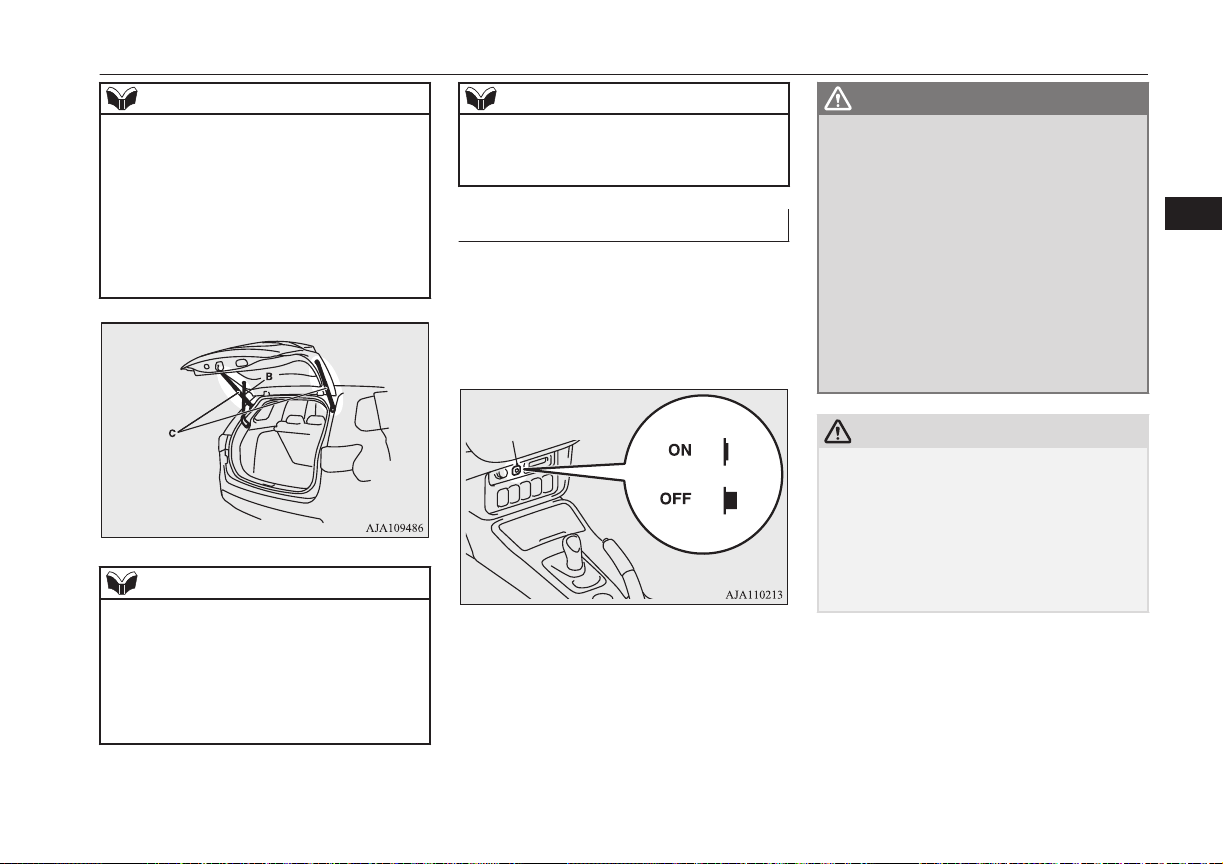
Electric tailgate*
NOTE
When opening and closing the electric tail-
l
gate, do not place your hands near the arm
(B).
Gas struts (C) are installed in the locations
l
shown below in order to support the electric
tailgate.
Make sure not to bump your head in the area
l
near the arm of the electric tailgate when
loading and unloading luggage.
NOTE
Please observe the following in order to pre-
l
vent damage or faulty operation.
Do not pull on the gas struts when closing
•
the electric tailgate or otherwise push or
pull them.
Do not attach any plastic material, tape,
•
etc., to the gas struts.
NOTE
Do not tie string, etc., around the gas
•
struts.
Do not hang anything from the gas struts.
•
Automatic operation
The electric tailgate can be operated using the
remote control switch on the keyless operation key, or the close switch on the tailgate
when the electric tailgate power switch (A) is
on.
E00313001089
WARNING
Turn off the electric tailgate power switch
l
when not operating the electric tailgate.
If the switch is left on, someone’s hand or
head could get caught if the electric tailgate switch or close switch is accidentally
operated, or children play with the controls.
If the electric tailgate power switch is
l
turned off while the tailgate is operating,
it will stop moving and switch to manual
operation.
At this time, the electric tailgate could
open or close suddenly, depending on its
position.
CAUTION
Do not apply excessive force on the electric
l
tailgate when opening or closing it. Doing so
could cause a breakdown.
Do not start the engine while the tailgate is
l
operating. The sudden operation prevention
mechanism could operate, making the electric tailgate stop intermittently while it
moves.
4
OGGE16E1
Locking and unlocking
4-21
Page 80

Electric tailgate*
NOTE
The electric tailgate cannot be opened when
l
the battery is flat or disconnected.
If you want to open the electric tailgate, it
can be opened by using the inside tailgate re-
4
lease.
Refer to “Inside tailgate release” on page
4-27.
If the keyless entry system or close switch is
l
operated when the electric tailgate power
switch is off, the warning buzzer sounds 4
times to notify the driver that the electric
tailgate cannot be operated.
The electric tailgate does not operate nor-
l
mally under the following conditions:
When parked on an incline
•
In strong winds
•
When the electric tailgate is covered with
•
snow
Repeated continuous operation between
l
opening and closing the electric tailgate will
activate the built-in protection circuit and
switch the tailgate to manual operation.
If the electric tailgate handle is operated
l
while the tailgate is operating or immediately after it is closed, the tailgate will move in
the direction opposite to the one in which it
was operating.
If the battery or fuse is replaced while the
l
electric tailgate is open, it cannot be closed
automatically.
In this case close the electric tailgate manually.
Operating conditions
The electric tailgate can be opened automatically when all of the following conditions are
met.
<Using the keyless operation key>
The operation mode is in OFF.
l
The electric tailgate is completely
l
closed.
The electric tailgate is unlocked.
l
<Using the driver’s side electric tailgate
switch>
The operation mode is in ON with the
l
electrical parking switch is pressed.
The electric tailgate is completely
l
closed.
The electric tailgate is unlocked.
l
<Using the open switch of the electric tailgate>
The electric tailgate is unlocked.
l
The keyless operation key is within the
l
operating range (70 cm from the electric
tailgate switch) and the tailgate is
locked.
The factory setting is “Inactive”.
To modify the setting to “Active”, please
contact an authorized MITSUBISHI
MOTORS dealer.
E00313101149
The electric tailgate can be closed automatically when all of the following conditions are
met.
<Using the keyless operation key>
The operation mode is in OFF.
l
The electric tailgate is completely open.
l
People, luggage, etc., are not touching
l
the sensors.
<Using the driver’s side electric tailgate
switch or close switch>
The operation mode is in ON with the
l
electrical parking switch is pressed.
The electric tailgate is completely open.
l
People, luggage, etc., are not touching
l
the sensors.
4-22
Locking and unlocking
OGGE16E1
Page 81

Electric tailgate*
Operating the electric tailgate
using the keyless operation key
or the driver’s side electric tailgate switch
After unlocking the doors and the electric
tailgate, the electric tailgate can be operated
by pressing the switch (A) of the keyless operation key or the driver’s side electric tailgate switch (B).
<Using the keyless operation key>
If the electric tailgate switch is pressed twice
in a row, the electric tailgate operates after
the warning buzzer sounds and the hazard
warning flasher brinks.
The electric tailgate operates as follows:
•While
closed:
The warning buzzer sounds
and the tailgate completely
opens.
•While
open:
If the electric tailgate switch is pressed once
while the tailgate is operating, the warning
buzzer sounds and it moves in the direction
opposite to the one in which it was operating.
The warning buzzer sounds
and the tailgate completely
closes.
NOTE
If the electric tailgate switch is pressed 3 or
l
more times in a row, the tailgate may not operate normally.
If this occurs, wait a short time before again
pressing the electric tailgate switch twice.
<Using the driver’s side electric tailgate
switch>
If the driver’s side electric tailgate switch is
pressed for more than about 1 second, the
electric tailgate operates after the buzzer
sounds and the hazard warning flasher blinks.
The electric tailgate operates as follows.
•While
closed:
•While
open:
The warning buzzer sounds
and the tailgate completely
opens.
The warning buzzer sounds
and the tailgate completely
closes.
If the driver’s side electric tailgate switch is
pressed once while the tailgate is operating,
the warning buzzer sounds and it moves in
the direction opposite to the one in which it
was operating.
WARNING
When operating the electric tailgate, en-
l
sure the safety of the surrounding area,
make sure there is sufficient space behind
and above the vehicle, and be careful not
to bump your head or catch your hands
or fingers.
Opening the electric tailgate using the open switch
The electric tailgate can be opened by pressing the open switch (C).
4
OGGE16E1
Locking and unlocking
4-23
Page 82

Electric tailgate*
If the open switch is pressed with the tailgate
and all doors are unlocked, the electric tailgate opens after the warning buzzer sounds
and the hazard warning flasher blinks.
When the tailgate and all doors are locked,
the warning buzzer will not sound.
4
NOTE
When you are carrying the keyless operation
l
key with the tailgate is locked, the electric
tailgate can be opened by pressing the open
switch even if the tailgate is locked.
The factory setting of the function is “Inactive”.
To modify the setting to “Active”, please
contact an authorized MITSUBISHI
MOTORS dealer.
Closing the electric tailgate using the close switch
The electric tailgate can be closed by pressing the close switch (D) on the inside of the
electric tailgate.
If the close switch on the inside of the electric tailgate is pressed, the electric tailgate
closes after the warning buzzer sounds and
the hazard warning flasher blinks.
If the close switch is pressed once while the
tailgate is closing, the warning buzzer sounds
and the electric tailgate opens.
NOTE
If the close switch is again pressed once
l
while the electric tailgate is operating in the
opening direction, the warning buzzer
sounds once and the electric tailgate closes.
Safety mechanism
The safety mechanism is activated if the electric tailgate should trap a person or an object
during automatic operation, or if the sensors
(A) on either side of the electric tailgate are
hit. The warning buzzer sounds once for safety and the electric tailgate automatically
moves in the direction opposite to the one in
which it was operating.
E00313200013
CAUTION
The safety mechanism will sometimes not
l
operate depending on the condition of the
trapped object or how it is trapped. Therefore, be especially careful not to trap a hand,
part of your body or an object at this time.
4-24
Locking and unlocking
OGGE16E1
Page 83

Electric tailgate*
CAUTION
The safety mechanism is cancelled just be-
l
fore the electric tailgate is fully closed to allow it to close completely. Therefore be especially careful not to trap a hand or finger
at this time.
The safety mechanism is deactivated when
l
the electric tailgate is closed manually.
Therefore be especially careful not to trap a
hand or finger at this time.
If the safety mechanism is repeatedly operat-
l
ed, the tailgate could be switched to manual
operation. Be careful at this time, as the
electric tailgate could open or close suddenly, depending on its position.
Once the electric tailgate is completely open
or closed, normal automatic operation is
again possible.
NOTE
If the environment or usage conditions sub-
l
ject the sensors to the same kind of force as
that of trapping a person or object, the safety
mechanism could be activated.
Do not damage the sensors when loading or
l
unloading luggage, or when cleaning the
rear window. Doing so could prevent the
tailgate from closing automatically.
Drop prevention mechanism
After the electric tailgate is opened automatically, if it is detected that the tailgate is dropping due to factors such as accumulated
snow, the electric tailgate is closed automatically.
A warning buzzer sounds continuously while
the drop prevention mechanism operates.
NOTE
If snow has accumulated on the electric tail-
l
gate, remove it before operation.
Do not install accessories other than
l
MITSUBISHI MOTORS GENUINE parts
on the electric tailgate. Some accessories
could be too heavy, causing the drop prevention mechanism to operate.
The drop prevention mechanism could be
l
activated if manual operation is attempted
immediately after the electric tailgate is
completely opened automatically.
Sudden operation prevention mechanism
If the engine is started while the electric tailgate is operating automatically, it may switch
to manual operation due to insufficient battery voltage, making the electric tailgate stop
intermittently while it moves. This is to stop
the electric tailgate from operating suddenly.
When the tailgate is completely closed or
opened, automatic operation is again possible
after approximately 10 seconds.
CAUTION
The safety mechanism is deactivated while
l
the sudden operation prevention mechanism
is operating. Therefore be especially careful
not to trap a hand or finger at this time.
Manual operation
If the electric tailgate power switch is off, the
electric tailgate can be operated by manual
operation.
E00313401067
4
OGGE16E1
Locking and unlocking
4-25
Page 84

Electric tailgate*
After unlocking the electric tailgate, push the
tailgate open switch (A) and pull up the tailgate.
4
CAUTION
Make sure there is no one around the electric
l
tailgate when opening it.
NOTE
If it does not open immediately after pushing
l
the tailgate open switch, the electric tailgate
cannot be lifted.
If this occurs, push the tailgate open switch
again and pull up the electric tailgate.
The electric tailgate cannot be opened when
l
the battery is flat or disconnected.
4-26
Locking and unlocking
To close the tailgate, pull the tailgate grip (B)
downward and release it before the tailgate is
completely closed, and then gently slam the
electric tailgate from the outside.
CAUTION
Do not fully close the electric tailgate with
l
your hand still on the tailgate grip. Doing so
could trap and injure your hand or arm.
The safety mechanism is deactivated when
l
the electric tailgate is closed manually.
Therefore be especially careful not to trap a
hand or finger at this time.
Tailgate easy closer
The tailgate easy closer is a mechanism for
assisting the closing of the electric tailgate.
If the electric tailgate is closed to a position
where it is detected as being ajar, it closes automatically.
OGGE16E1
E00313300069
WARNING
Be careful not to catch your hands or fin-
l
gers when the electric tailgate closes automatically from the door ajar position. If
you think your hands or fingers could be
caught during the operation of the tailgate
easy closer, pull the handle of the electric
tailgate. The electric tailgate will return to
the door ajar position.
CAUTION
Do not touch the latch (A) on the inside of
l
the electric tailgate. The tailgate easy closer
could operate and catch your fingers.
NOTE
The tailgate easy closer operates even when
l
the electric tailgate power switch is OFF.
Page 85

Electric tailgateTailgate
Inside tailgate release
NOTE
Repeated continuous operation of the handle
l
could activate the protection circuit and temporarily prevent the tailgate easy closer from
operating.
If this occurs, wait about 1 minute before
operating the tailgate easy closer again.
Inside tailgate release
E00303400298
The inside tailgate release is designed to provide a way to open the tailgate in the case of
a discharged battery.
The tailgate release (see illustration) is mounted on the tailgate.
You and your family should familiarise yourselves with the location and operation of the
tailgate release.
To open
1. Open the lid (A) inside of the tailgate.
2. Move the lever (B) to open the tailgate.
3. Push out on the tailgate to open it.
CAUTION
Always keep the release lever lid on the tail-
l
gate closed when driving so that your luggage cannot accidentally bump against the
lever and open the tailgate.
Security alarm system*
E00301501999
The security alarm system is for alerting the
surrounding area of suspicious behaviour to
prevent unlawful entry into the vehicle by operating an alarm if a door, the tailgate or the
bonnet is opened when the vehicle has not
been unlocked using the keyless entry system
or the keyless operation function.
Also, the alarm will be activated if any of the
following occur.
Attempt an unlawful moving of the vehi-
l
cle. (the impact detection function)
Detect a motion in the vehicle. (the inte-
l
rior intrusion detection function)
Disconnect the battery terminal.
l
The security alarm system is set to “active”.
When making changes to the settings, please
follow the procedure listed in the section titled “Changing the security alarm settings”
on page 4-29.
4
OGGE16E1
Locking and unlocking
4-27
Page 86

Security alarm system*
On vehicles equipped with MITSUBISHI
Multi-Communication System (MMCS),
screen operations can be used to make the adjustment. Refer to the separate owner’s manual for details.
4
CAUTION
Do not modify or add parts to the security
l
alarm system.
Doing so could cause the security alarm to
malfunction.
NOTE
The alarm system will not be activated if the
l
doors and the tailgate have been locked using a key, the inside lock knob or the central
door lock switch (instead of the keyless entry system or the keyless operation function).
NOTE
If the turn-signal lamps do not blink after the
l
locking and unlocking operation using the
keyless entry system or the keyless operation
function, the security alarm system may be
malfunctioning.
Have the vehicle inspected at a
MITSUBISHI MOTORS Authorized Service Point.
If the confirmation function (blinking of the
turn-signal lamps by locking and unlocking
the doors and the tailgate) is deactivated, the
turn-signal lamps do not blink after the locking and unlocking operation.
For information on the confirmation function, refer to “Keyless entry system” on page
4-03 and “To operate using the keyless operation function” on page 4-09.
The security alarm system could be activated
l
in the following situations.
Using a car wash.
•
Taking the vehicle on a ferry.
•
Parking in an automated car park.
•
Leaving someone or a pet in the vehicle.
•
Leaving a window or the sunroof open.
•
Leaving an unstable object such as a stuf-
•
fed toy or accessory in the vehicle.
Suffering a continuous impact or vibra-
•
tion by hail, thunder, etc.
NOTE
Air flows by the Remote Climate Control.
•
According to the situations, please deactivate the vehicle inclination detection
function and the interior intrusion detection function.
Refer to “To deactivate the vehicle inclination detection function and the interior
intrusion detection function” on page
4-32.
The sensitivity of the interior intrusion de-
l
tection function can be adjusted. For details,
please contact a MITSUBISHI MOTORS
Authorized Service Point.
4-28
Locking and unlocking
OGGE16E1
Page 87

Security alarm system*
The security alarm has four modes:
System preparation mode (approx. 20 seconds)
(The buzzer sounds intermittently and the security indicator (A) blinks.)
The system preparation time extends from
the point at which all of the doors and the
tailgate are locked by pressing the LOCK
switch on the remote control switch or the
keyless operation function to the point at
which the system armed mode goes into effect.
During this time, it is possible to temporarily
open a door or the tailgate without using the
keyless entry system or the keyless operation
function and without causing the alarm to
sound (for example, when you forget something inside the vehicle or realize that a window is open).
System armed mode
(The buzzer stops and the security indicator
continues to blink with the indicator’s reduced lit-up duration time.)
Once the system preparation mode has ended,
the system armed mode starts.
If an unlawful opening of any of the doors,
tailgate or bonnet is detected during the system armed mode, the alarm will be activated
to warn people around the vehicle of an abnormal condition.
Also, if unlawful moving of the vehicle is attempted or a vehicle intrusion is detected, the
alarm will be activated.
Alarm activation
The turn-signal lamps blink and the siren
sounds for approximately 30 seconds.
Refer to “Alarm activation” on page 4-33.
NOTE
The alarm will resume if unlawful actions
l
are taken again, even if the alarm has stopped.
System cancellation
It is possible to cancel the system activation
during the system preparation mode or the
system armed mode.
In addition, it is possible to cancel the alarm
once it has been activated.
Refer to “Cancelling the system” on page
4-32, “Cancelling the alarm” on page 4-33.
NOTE
When lending the vehicle to another person
l
or allowing the vehicle to be driven by
someone who is unfamiliar with the security
alarm system, be sure to give the person a
proper explanation of the security alarm system.
If a person who is unfamiliar with the security alarm system accidentally unlocked the
vehicle, causing the alarm to sound, the
alarm would be a nuisance to people nearby.
Changing the security alarm settings
It is possible to set the security alarm to the
“active” mode or “inactive” mode.
E00301601365
4
OGGE16E1
Locking and unlocking
4-29
Page 88

Security alarm system*
Follow the procedure below.
1. Put the operation mode in OFF.
2. Place the lamp switch in the “OFF” position, and leave the driver’s door open.
4
3. Pull the windscreen wiper and washer
switch towards you and hold it there.
(Since the operation mode in OFF,
washer fluid will not be sprayed.)
4. After approximately 10 seconds, the
buzzer will make a sound. Keep the
windscreen wiper and washer switch
pulled towards you. (If the windscreen
wiper and washer switch was released,
the setting change mode would be cancelled. To start over, perform the procedure again from step 3.)
5. When the buzzer stops, with the windscreen wiper and washer switch still
pulled towards you, press the UNLOCK
switch (A) on the remote control switch
to select the security alarm settings
mode.
The settings mode can be toggled by
pressing the UNLOCK switch. The
mode can be confirmed from the number
of times the buzzer sounds.
Number of
times the
buzzer
sounds
1 Alarm inactive
2 Alarm active
6. Any of the following operations can be
used to terminate the system settings
change mode.
• Releasing the windscreen wiper and
washer switch.
• Closing the driver’s door.
Security alarm settings
mode
4-30
Locking and unlocking
OGGE16E1
Page 89
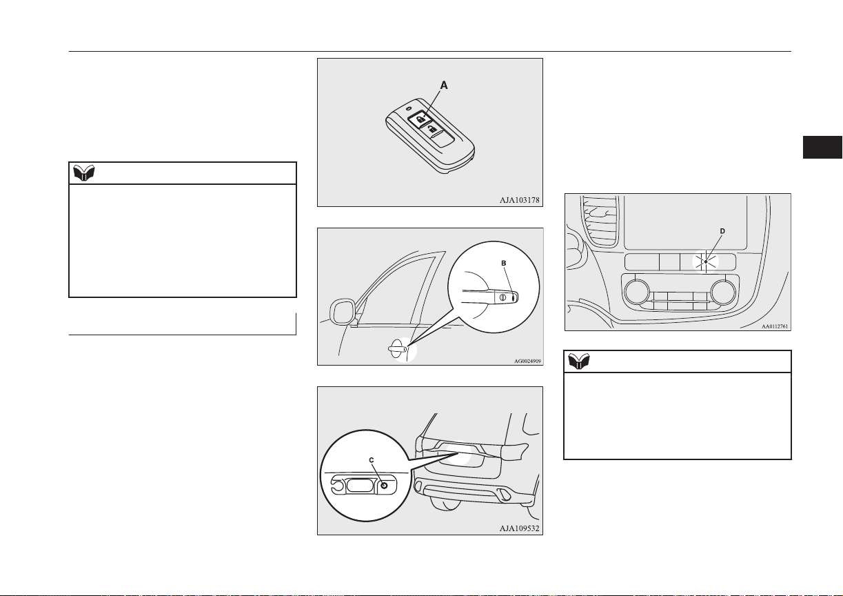
Driver’s and front passenger’s door look/unlock switches*
Tailgate LOCK switch*
Security alarm system*
• Put the operation mode in ON or
ACC.
• Placing the lamp switch in any position other than “OFF”.
• Allowing 30 seconds to pass without
making any changes to the settings.
NOTE
If anything with regard to making changes to
l
the security alarm system settings is hard to
understand, please consult your
MITSUBISHI MOTORS Authorized Service Point.
Avoid leaving valuable items inside the ve-
l
hicle even when the security alarm system
has been set to the “active” mode.
Setting the system
Follow the procedure below to set the system
to the system armed mode.
1. Put the operation mode in OFF.
2. Exit the vehicle and close all of the
doors, tailgate and bonnet.
3. Press the LOCK switch (A) on the remote control switch of the keyless operation key, the driver’s or front passenger’s door lock/unlock switch (B), or the
tailgate LOCK switch (C) in order to
lock all the doors and the tailgate.
E00301702190
By locking the vehicle using the keyless
entry system or the keyless operation
function, the system preparation mode is
activated.
The buzzer makes an intermittent beeping sound and the security indicator (D)
in the centre panel flashes for confirmation.
NOTE
The system preparation mode is not activa-
l
ted when the doors and the tailgate have
been locked using a method other than the
keyless entry system or the keyless operation
function (namely a key, the inside lock knob
or the central door lock switch).
4
OGGE16E1
Locking and unlocking
4-31
Page 90

Security alarm system*
NOTE
If the bonnet is open, the security indicator
l
illuminates, and the system does not enter
the system preparation mode.
When the bonnet is closed, the system enters
4
the system preparation mode, and after approximately 20 seconds the system enters
the system armed mode.
4. After approximately 20 seconds, the
buzzer stops, and when the blinking of
the security indicator starts to slow
down, the system armed mode goes into
effect.
The security indicator continues to blink
during the system armed mode.
NOTE
The security alarm system can be activated
l
when people are riding inside the vehicle or
when the windows are open. To prevent accidental activation of the alarm, do not set
the system to the system armed mode while
people are riding in the vehicle.
Avoid leaving valuable items inside the ve-
l
hicle even when the security alarm system
has been set to the “active” mode.
To deactivate the vehicle inclination detection function and
the interior intrusion detection
function
E00312101429
The vehicle inclination detection function
and the interior intrusion detection function
can be deactivated when parking in automated car parks, when leaving pets in the vehicle or when leaving the vehicle with the windows slightly open.
1. Put the operation mode in OFF.
2. Raise and hold the wiper and washer
switch to the “MIST” position for approximately 3 seconds. The buzzer will
sound once and the function will be deactivated.
To activate the function again, raise and hold
the wiper and washer switch to the “MIST”
position for approximately 3 seconds.
The buzzer will sound twice and the function
will be activated.
NOTE
The function will be activated again if the following operation is performed.
If the doors and the tailgate are unlocked us-
l
ing the keyless entry system or the keyless
operation function.
If the operation mode is put in on or ACC.
l
Cancelling the system
The following methods can be used to cancel
the system when it is in the system preparation mode or the system armed mode.
Pressing the UNLOCK switch on the re-
l
mote control switch.
Putting the operation mode in ON.
l
E00301801875
4-32
Locking and unlocking
OGGE16E1
Page 91

Opening any one of the doors or the tail-
l
gate, when the system is in the system
preparation mode.
Holding the keyless operation key and
l
pressing the driver’s or front passenger’s
door lock/unlock switch, or the tailgate
open switch to unlock the doors and the
tailgate.
NOTE
If the bonnet is opened during the system
l
preparation mode, the system preparation
mode is suspended.
The system returns to the system preparation
mode when the bonnet is closed.
If the battery terminals are disconnected
l
while the system is in the system preparation
mode, the memory will be erased.
It is possible to register up to 4 remote con-
l
trol switches for keyless operation system.
As long as they are registered, any of the remote control switches, other than the one
used to activate the system, can be used to
cancel the system.
If you want to register additional remote
control switches, please contact a
MITSUBISHI MOTORS Authorized Service Point.
NOTE
The activation distance for keyless entry sys-
l
tem is approximately 4 m.
If it is not possible to lock or unlock the vehicle by pressing the switch at the correct
distance or the security alarm system cannot
be set or cancelled using the switch, the battery may need to be replaced.
Replace the battery at a MITSUBISHI
MOTORS Authorized Service Point.
If the UNLOCK switch on the remote con-
l
trol switch, or the driver’s or front passenger’s door lock/unlock switch is pressed and
no door or the tailgate is opened within 30
seconds, the doors and the tailgate will automatically relock. In this case as well, the
system preparation mode will go into effect.
The time between pressing the UNLOCK
l
switch on the remote control switch, or the
driver’s or front passenger’s door lock/
unlock switch and automatic locking can be
adjusted. Consult a MITSUBISHI MOTORS
Authorized Service Point.
On vehicles equipped with MITSUBISHI
Multi-Communication System (MMCS),
screen operations can be used to make the
adjustment. Refer to the separate owner’s
manual for details.
Security alarm system*
Alarm activation
E00301900941
When the system is in the system armed
mode, the alarm will be activated as follows
if the vehicle is unlocked or if any of the
doors, tailgate or bonnet is opened using a
method other than the keyless entry system or
the keyless operation function.
1. The alarm will be activated for approximately 30 seconds.
The turn-signal lamps will flash, and the
siren will sound intermittently.
2. The alarm will resume if unlawful actions are taken again, even if the alarm
has stopped.
4
OGGE16E1
Cancelling the alarm
It is possible to halt the activation of an alarm
using the following methods:
Locking and unlocking
E00302001702
4-33
Page 92
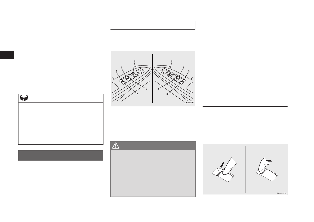
Driver’s switch RHD
Driver’s switch LHD
Electric window control
Pressing the LOCK or UNLOCK switch
l
on the remote control switch.
(After pressing the LOCK switch, the
vehicle will lock if all the doors and the
tailgate are closed, after which the sys-
4
tem preparation mode will once again go
into effect.)
Putting the operation mode in ON.
l
Holding the keyless operation key and
l
locking or unlocking the doors and the
tailgate using the keyless operation function.
NOTE
When the operation mode is put in ON, the
l
buzzer sounds 4 times. This operation indicates that the alarm was activated while the
vehicle was parked.
Please check the inside of the vehicle to confirm that nothing was stolen.
Even if the battery is disconnected, the alarm
l
activation memory will not be erased.
Electric window control
The electric windows can only be operated
with the operation mode in ON.
E00302201632
Electric window control switch
Each door window opens or closes while the
corresponding switch is operated.
1- Driver’s door window
2- Front passenger’s door window
3- Rear left door window
4- Rear right door window
5- Lock switch
E00302301822
WARNING
Before operating the electric window con-
l
trol, make sure that nothing can get trapped (head, hand, finger, etc.).
Never leave the vehicle without removing
l
the key.
Never leave a child (or other person who
l
might not be capable of safe operation of
the electric window control) in the vehicle
alone.
Driver’s switches
The driver’s switches can be used to operate
all door windows. A window can be opened
or closed by operating the corresponding
switch.
Press the switch down to open the window,
and pull up the switch to close it.
If the switch for the driver’s window is fully
pressed down/pulled up, the door window automatically opens/closes completely.
If you want to stop the window movement,
operate the switch lightly in the reverse direction.
Passenger’s switches
The passenger’s switches can be used to operate the corresponding passenger’s door
windows.
Press the switch down for opening the window, and pull up the switch for closing it.
4-34
Locking and unlocking
OGGE16E1
Page 93
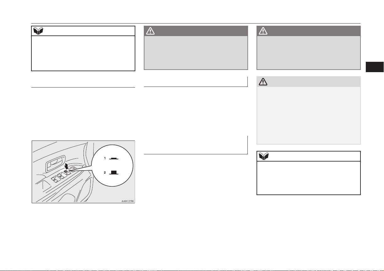
Electric window control
NOTE
Repeated operation with the engine stopped
l
will run down the battery. Operate the window switches only while the engine is running.
The rear door windows only open halfway.
l
Lock switch
When this switch is operated, the passenger’s
switches cannot be used to open or close the
door windows and the driver’s switch cannot
open or close any door windows other than
the driver’s door window.
To unlock, press it once again.
1- Lock
2- Unlock
E00303101263
WARNING
A child may tamper with the switch at the
l
risk of its hands or head being trapped in
the window. When driving with a child in
the vehicle, please press the window lock
switch to disable the passenger’s switches.
Timer function
The door windows can be opened or closed
for 30 seconds after putting the operation
mode in OFF or ACC from ON.
However, once the driver’s door or the front
passenger’s door is opened, the windows cannot be operated.
E00302402051
Safety mechanism (driver’s window only)
If a hand or head is trapped in the closing
window, it will lower automatically.
Nonetheless, make sure that nobody puts
their head or hand out of the window when
closing the driver’s door window.
The lowered window will become operational after a few seconds.
E00302500830
WARNING
If the battery terminals are disconnected
l
or the fuse for electric window is replaced,
the safety mechanism will be cancelled.
If a hand or head got trapped, a serious
injury could result.
CAUTION
The safety mechanism is cancelled just be-
l
fore the window is fully closed. This allows
the window to close completely. Therefore
be especially careful that no fingers are trapped in the window.
The safety mechanism is deactivated while
l
the switch is pulled up. Therefore be especially careful that fingers are not trapped in
the door window opening.
NOTE
The safety mechanism can be activated if the
l
driving conditions or other circumstances
cause the driver’s door window to be subjected to a physical shock similar to that caused
by a trapped hand or head.
4
OGGE16E1
Locking and unlocking
4-35
Page 94

Sunroof*
NOTE
If the battery terminals are disconnected or
l
the fuse for electric window is replaced, the
safety mechanism will be cancelled and the
door window will not automatically open/
4
close completely.
If the window is open, repeatedly raise the
driver’s door window switch until the window has been fully closed. Following this,
release the switch, raise the switch once
again and hold it in this condition for at least
1 second, then release it. You should now be
able to operate the driver’s door window in
the normal fashion.
Sunroof*
The sunroof can only be operated with the
operation mode in the “ON”.
E00302702357
To open
The sunroof automatically opens if the switch
(1) is pressed.
To stop the moving sunroof, press the switch
(2) or (3).
NOTE
The sunroof automatically stops just before
l
reaching the fully open position.
Press the switch again to fully open it.
To close
The sunroof automatically closes while the
switch (3) is pressed.
To stop the moving sunroof, press switch (1)
or (2).
To tilt up
When the switch (2) is pressed, the rear edge
of the sunroof rises for ventilation.
To tilt down
The sunroof tilts down while the switch (3) is
pressed.
Nonetheless, make sure that nobody puts
their head or hand out of the sunroof when
opening or closing.
The opened sunroof will become operational
after a few seconds.
If the safety mechanism should be activated 5
or more times consecutively, normal closing
of the sunroof will be aborted.
As an emergency measure, the sunroof can
be closed bit by bit until the sunroof is completely closed by repeatedly pressing switch
(2).
After that, the sunroof can be set the initialized state in the following procedure.
1. Move the sunroof in slide open position.
2. Press the tilt up switch (2) continually in
10 seconds.
3. The sunroof will be moved to tilt up position automatically bit by bit.
4. The initialize is completed when the
sunroof is stopped at tilt up position.
If the sunroof does not return to normal, consult a MITSUBISHI MOTORS Authorized
Service Point.
4-36
Locking and unlocking
Safety mechanism
E00303801404
If a hand or head is trapped in the closing
sunroof, it will re-open automatically.
OGGE16E1
Page 95

Sunroof*
NOTE
The safety mechanism can be activated if the
l
driving conditions or other circumstances
cause the sunroof to be subjected to a physical shock similar to that caused by a trapped
hand or head.
CAUTION
The safety mechanism is cancelled just be-
l
fore the sunroof is fully closed. This allows
the sunroof to close completely.
Therefore be especially careful that no fingers are trapped in the sunroof.
WARNING
Before operating the sunroof, make sure
l
that nothing is capable of being trapped
(head, hand, finger, etc.).
Do not put head, hands or anything else
l
out of the sunroof opening while driving
the vehicle.
Never leave the vehicle without removing
l
the key.
Never leave a child (or other person who
l
might not be capable of safe operation of
the sunroof switch) in the vehicle alone.
NOTE
The sunroof stops just before reaching the
l
fully open position.
If the vehicle is driven with the sunroof in
this position, wind buffeting is lower than
with the sunroof fully open.
When leaving the vehicle unattended, make
l
sure you close the sunroof.
Do not try to operate the sunroof if it is fro-
l
zen closed (after snow fall or during extreme
cold).
Do not sit or place heavy luggage on the
l
sunroof or roof opening edge.
Release the switch as soon as the sunroof
l
reaches the fully open or fully closed position.
If the sunroof does not operate when the
l
sunroof switch is operated, release the
switch and check whether something is trapped by the sunroof. If nothing is trapped,
have the sunroof checked at an authorized
MITSUBISHI MOTORS dealer.
Depending on the models of ski carriers or
l
roof carriers, the sunroof may contact the
carrier when the sunroof is tilted up. Be
careful when tilting up the sunroof if such a
ski carrier or a roof carrier is installed.
Be sure to close the sunroof completely
l
when washing the vehicle or when leaving
the vehicle.
Be careful, not to put any wax on the weath-
l
erstrip (black rubber) around the sunroof
opening. If stained with wax, the weatherstrip cannot maintain a weatherproof seal
with the sunroof.
NOTE
After washing the vehicle or after it has
l
rained, wipe off any water that is on the sunroof before operating it.
Sunshade
Slide the sunshade manually to open and
close it.
E00307901227
CAUTION
Be careful that hands are not trapped when
l
closing the sunshade.
NOTE
The sunshade cannot be closed with the sun-
l
roof opened. Do not attempt to close the
sunshade when the sunroof is opened.
4
OGGE16E1
Locking and unlocking
4-37
Page 96

OGGE16E1
Page 97

Seats and seat belts
Seat arrangement.................................................................................5-02
Seat adjustment................................................................................... 5-02
Front seats........................................................................................... 5-03
Rear seats............................................................................................ 5-05
Head restraints.....................................................................................5-05
Making a luggage area........................................................................ 5-07
Making a flat seat................................................................................5-08
Seat belts............................................................................................. 5-09
Pregnant women restraint....................................................................5-14
Seat belt pretensioner system and force limiter system...................... 5-14
Child restraint......................................................................................5-15
Seat belt inspection............................................................................. 5-28
Supplemental restraint system (SRS) - airbag.................................... 5-29
5
OGGE16E1
Page 98

Seat arrangement
Seat arrangement
By operating the front or rear seat, select the desired seat arrangement.
Normal usage
5
Flat seat ® p. 5-08
Making a luggage area Folding the rear seats ® p. 5-07
Seat adjustment
E00400300662
Adjust the driver’s seat so that you are comfortable and that you can reach the pedals,
steering wheel, switches etc. while retaining
a clear field of vision.
E00400201886
5-02
Seats and seat belts
OGGE16E1
Page 99

Front seats
WARNING
Do not attempt to adjust the seat while
l
driving. This can cause loss of vehicle control and result in an accident. After adjustments are made, ensure the seating is
locked in position by attempting to move
the seat forward and rearward without
using the adjusting mechanism.
Do not allow people or children to ride in
l
any area of your vehicle that is not equipped with seats and seat belts, and make
sure that everyone travelling in your vehicle is in a seat and wearing a seat belt, or
in the case of a child is strapped in a child
restraint.
To minimize the risk of personal injury in
l
the event of a collision or sudden braking,
the seatbacks should always be in the almost upright position while the vehicle is
in motion. The protection provided by the
seat belts may be reduced significantly
when the seatback is reclined. There is
greater risk that the passenger will slide
under the seat belt, resulting in serious injury, when the seatback is reclined.
CAUTION
Make sure the seat is adjusted by an adult or
l
with adult supervision for correct and safe
operation.
CAUTION
Do not place a cushion or the like between
l
your back and the seatback while driving.
The effectiveness of the head restraints will
be reduced in the event of an accident.
The reclining mechanism of the front seat’s
l
seatback is spring loaded, causing it to return
to the vertical position when the lock lever is
operated. When using the lever, sit close to
the seatback or hold it with your hand to
control its return motion.
When sliding the seats, be careful not to
l
catch your hand or foot.
When adjusting the front seat while the rear
l
seat is folded, be careful not to apply strong
force to the flipped rear seat cushion.
Doing so could cause damage to the cover of
the front seat and the fitting of the rear seat
cushion.
Front seats
E00400401253
Manual type
5
1- To adjust forward or backward
Lift the handle and adjust the seat to the
desired position, and release the handle.
2- To recline the seatback
Pull the lever up and then lean backward
to the desired position, and release the
lever.
3- To adjust seat height (driver’s side only)
Repeatedly operate the lever and adjust
the seat height to the desired position.
OGGE16E1
Seats and seat belts
5-03
Page 100

Front seats
Power type*
5
1- To adjust forward or backward
Operate the switch as indicated by the
arrows and adjust the seat to the desired
position.
2- To recline the seatback
Operate the switch as indicated by the
arrows and adjust the seatback angle to
the desired position.
3- To adjust seat height
Operate the switch as indicated by the
arrows and adjust the seat height to the
desired position.
If the entire switch is operated, then the
entire seat moves.
Heated seats*
The heated seats can be operated with the operation mode of the power switch in ON. Operate the switch as indicated by arrows.
5-04
Seats and seat belts
E00401102283
The indication lamp (A) will illuminate while
the heater is on.
1 (HI) - Heater high (for quick heating).
2 - Heater off.
3 (LO) - Heater low (to keep the seat
warm).
CAUTION
Operate in the high position for quick heat-
l
ing. Once the seat is warm, set the heater to
low to keep it warm. Slight variations in seat
temperature may be felt while using the
heated seats. This is caused by the operation
of the heater’s internal thermostat and does
not indicate a malfunction.
If the following types of persons use the
l
heated seats, they might become too hot or
OGGE16E1
CAUTION
receive minor burns (red skin, heat blisters,
etc.):
Children, elderly or ill people
•
People with sensitive skin
•
Excessively tired people
•
People under the influence of alcohol or
•
sleep inducing medication (cold medicine,
etc.)
Do not place heavy objects on the seat or
l
stick pins, needles, or other pointed objects
into it.
Do not use a blanket, cushion, or other mate-
l
rial with high heat insulation properties on
the seat while using the heater; this might
cause the heater element to overheat
Do not use benzine, kerosene, petrol, alcohol
l
or other organic solvents when cleaning the
seats. Doing so could damage not only the
seat cover, but also the heater element.
If water or any other liquid is spilled on the
l
seat, allow it to dry thoroughly before attempting to use the heater. Turn the heater
off immediately if it appears to be malfunctioning during use.
 Loading...