

Page 1
BK0203201EN.book 1 ページ 2013年11月19日 火曜日 午前11時50分
Foreword
E09200105565
Thank you for selecting a MITSUBISHI MOTORS product as your new vehicle.
This owner’s manual will add to your understanding and full enjoyment of the many fine features of this vehicle.
It contains information prepared to acquaint you with the proper way
to operate and maintain your vehicle for the utmost in driving pleasure.
MITSUBISHI MOTORS AUSTRALIA LTD., reserves the right to
make changes in design and specifications and/or to make additions to
or improvements in this product without obligation to install them on
products previously manufactured.
It is an absolute requirement for the driver to strictly observe all laws
and regulations concerning vehicles.
This owner’s manual has been written in compliance with such laws
and regulations, but some of the contents may become contradictory
with later amendment of the laws and regulations.
Please leave this owner’s manual in this vehicle at time of resale. The
next owner will appreciate having access to the information contained
in this owner’s manual.
Throughout this owner’s manual the words WA RN I N G and CAU-
TION appear.
These serve as reminders to be especially careful. Failure to follow
instructions could result in personal injury or damage to your vehicle.
indicates a strong possibility of severe personal injury or death if
instructions are not followed.
means hazards or unsafe practices that could cause minor personal injury or damage to your vehicle.
Yo u wi l l s ee a n ot he r i m po rt a nt sym b ol :
NOTE: gives helpful information.
*: indicates optional equipment.
It may differ according to the sales classification; refer to the
sales catalogue.
©2013 Mitsubishi Motors Corporation
Page 2
1
2
3
4
5
6
7
8
9
10
11
12
13
BK0203201EN.book 1 ページ 2013年11月19日 火曜日 午前11時50分
Table of contents
Overview
General information
Charging
Locking and unlocking
Seat and seat belts
Instruments and controls
Starting and driving
For pleasant driving
For emergencies
Vehicle care
Maintenance
Specifications
Alphabetical index
Page 3
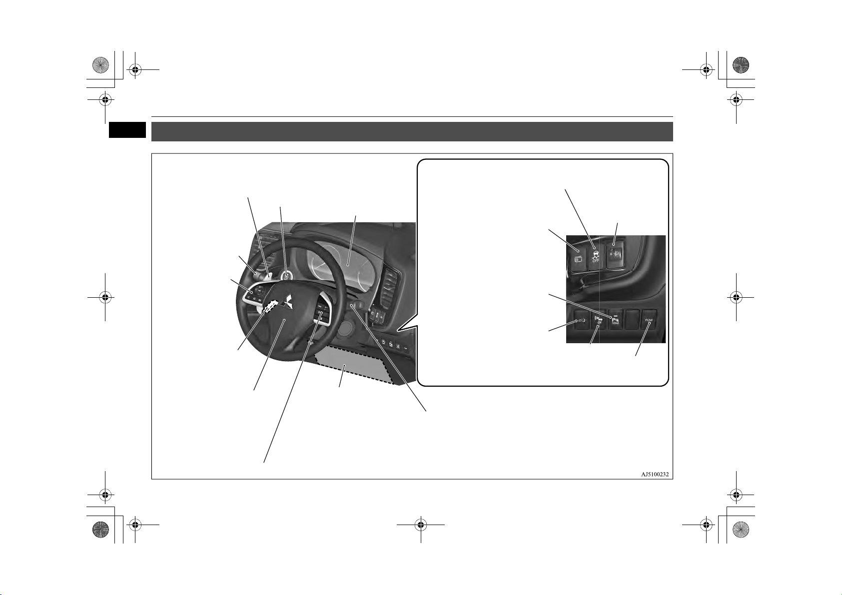
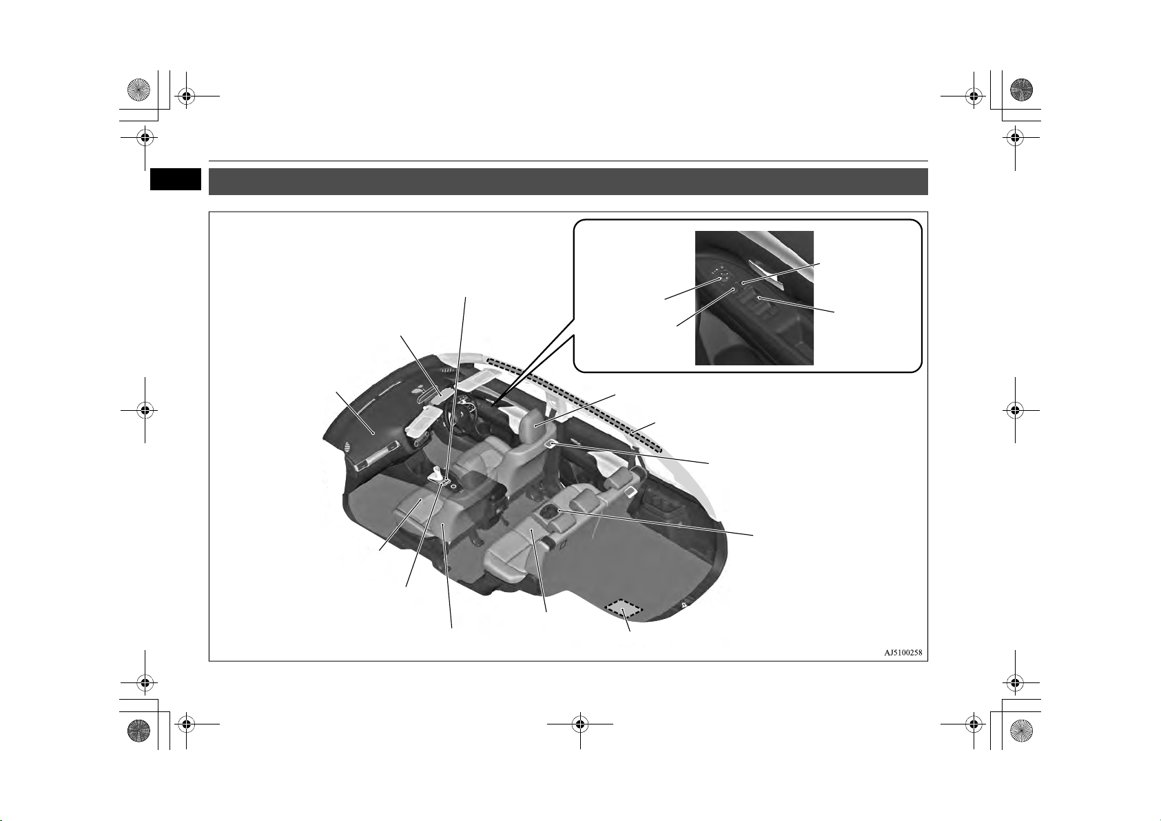
Wind screen wiper and
washer switch P.6-47
Rear window wiper and
washer switch P.6-51
Steering wheel audio
remote control
switches* P.8-24
Supplemental restraint system airbag (for driver ’s seat) P.5-21,
5-23
Horn switch P.6-54
Cruise control switch* P.7-35
Supplemental restraint system
(SRS) - front knee airbag (for
driver’s seat)* P.5-24
Combination headlamps and dipper switch P.6-40
Turn-signal lever P.6-45
Front fog lamp switch P.6-46
Headlamp washer switch* P.6-52
Active stability control (ASC) OFF
switch P.7-33
Headlamp levelling
switch* P.6-44
Instruments P.6-2
Regenerative braking level
selector (paddle) P.7-17
Power switch P.7-10
Steering wheel height and
reach adjustment lever P.7-6
Multi information display
switch P.6-4
Sonar switch* P.7-65
Driver’s side electric tailgate
switch* P.4-17
Acoustic Vehicle Alerting System (AVAS) OFF switch
P. 7 - 2 5
Forward Collision Mitigation System
(FCM) ON/OFF switch* P.7-59
BK0203201EN.book 1 ページ 2013年11月19日 火曜日 午前11時50分
Instruments and Controls
1
Instruments and Controls
E00100108168
1-1
Overview
Page 4
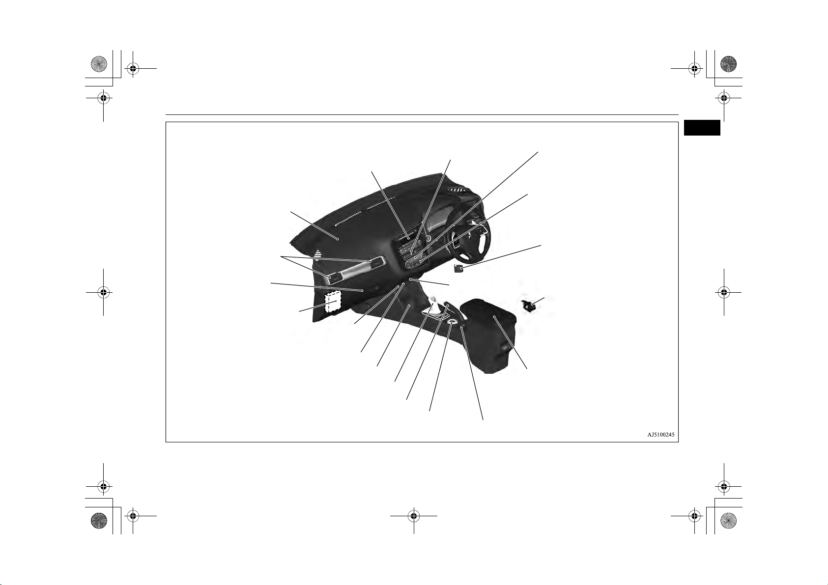
Audio*
Mitsubishi Multi Communication System (MMCS)*
[For DISPLAY AUDIO and MMCS, refer to the separate
owner’s manuals.]
Digital clock*
Accessory socket* P.8-66
4WD lock switch P.7-19
Glove box P.8-68
Card holder P.8-68
Passenger’s ventilators
P. 8- 2
Bonnet release lever
P. 11 -3
Key slot P.7-13
Fuel tank filler door release
lever P.2-13
Parking brake lever P.7-4
Selector lever (Joystick Type) P.7-14
Hazard warning flasher switch
P. 6 - 4 5
Air conditioner P.8-4
Rear window demister switch P.6-53
Wipe r d eicer switch * P.6-53
Fuse box P.11-15
Supplemental restraint system (SRS) - airbag
(for front passenger’s seat) P.5-23
Floor console box P.8-69
Armrest
Accessory socket P.8-66
USB input terminal P.8-61
Heated seat switch* P.5-4
Cup holder P.8-70
Electric tailgate power switch* P.4-17
BK0203201EN.book 2 ページ 2013年11月19日 火曜日 午前11時50分
Instruments and Controls
1
Overview 1-2
Page 5
Supplemental restraint system - airbag
(for front passenger’s seat) P.5-21,
5-23
Room lamp (Front) P.8-67, 11-23
Front seat P.5-3
Heated seats* P.5-4
Supplemental restraint system - side airbag
(for front seat)* P.5-27
Rear seat P.5-5
Supplemental restraint system curtain airbag* P.5-27
Armrest P.5-5
Cup holder P.8-70
Electric remote-controlled
outside rear-view mirrors
switch P.7-7
Central door lock
switch P.4-15
Lock switch
P. 4 - 3 0
Electric window
control switch
P. 4- 2 9
Head restraints P.5-5
Battery save switch P.7-22
Battery charge switch P.7-23
Auxiliary battery P.11-8
Room lamp (Rear) P.8-67, 11-23
BK0203201EN.book 3 ページ 2013年11月19日 火曜日 午前11時50分
Interior
1
Interior
E00100206107
1-3 Overview
Page 6
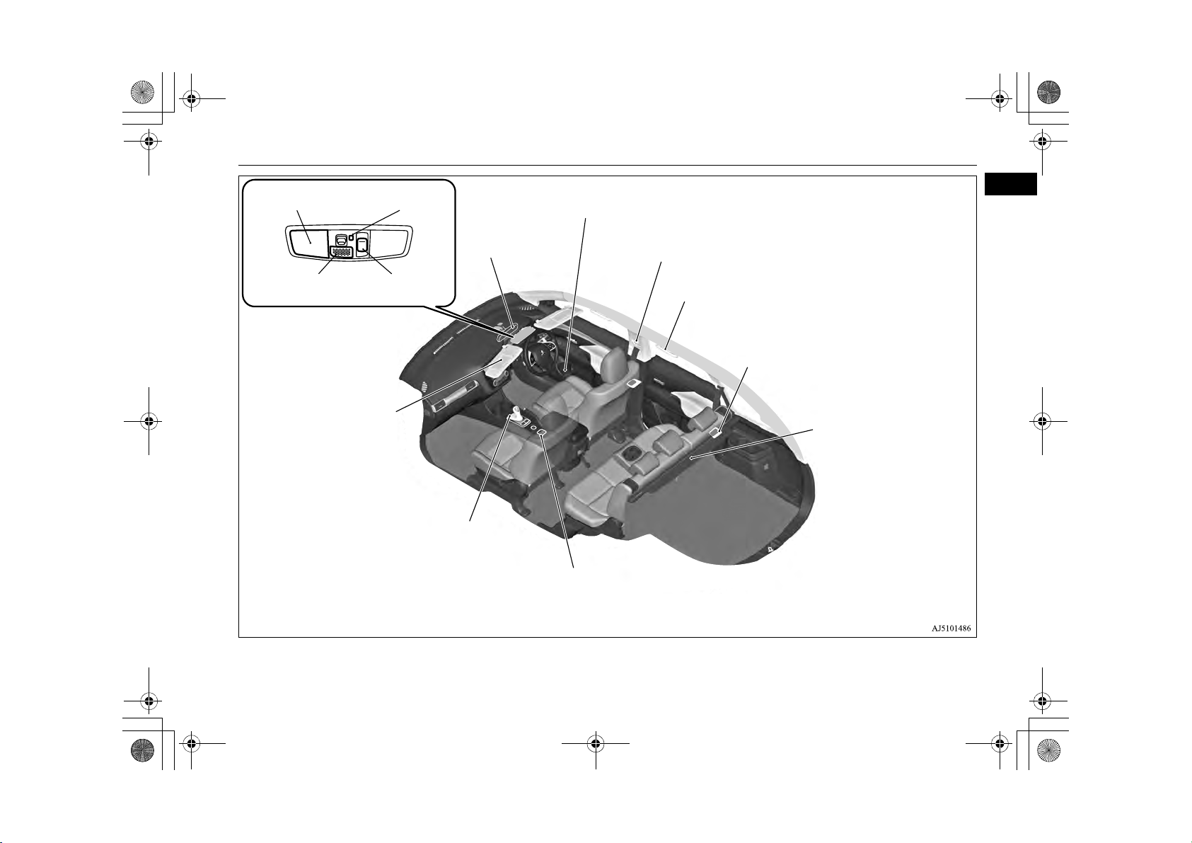
Sun visors P.8-64
Vanity mirror P.8-64
Card holder P.8-64
Inside rear-view mirror
P.7-6
Bottle holder P.8-71
Assist grips P.8-72
Coat hook P.8-72
Adjustable seat belt anchor P.5-12
Seat belts P.5-9
Luggage room lamp
P. 8- 6 8, 11 - 23
Heated seat switch* P.5-4
Electrical parking switch
P. 7- 1 6
Cargo area cover
P. 8- 7 1
Sunroof switch*
P. 4- 3 1
Map & room lamps (front)
P.8-67, 11-23
Hands-free microphone*
P.8-42
Downlight
P. 8- 6 6
BK0203201EN.book 4 ページ 2013年11月19日 火曜日 午前11時50分
Interior
1
Overview 1-4
Page 7
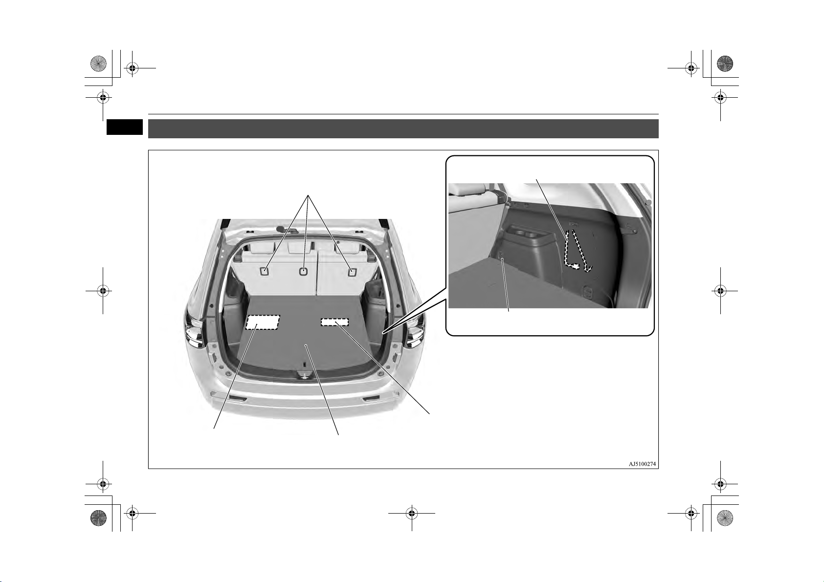
Too ls P.9 -6
Luggage hook P.8-73
Tyr e re pai r ki t P.9- 7
Tether anchorages for child restraint system P.5-16
Jack P.9-6
Luggage floor box P.8-69
BK0203201EN.book 5 ページ 2013年11月19日 火曜日 午前11時50分
Luggage area
1
Luggage area
E00100402794
1-5 Overview
Page 8
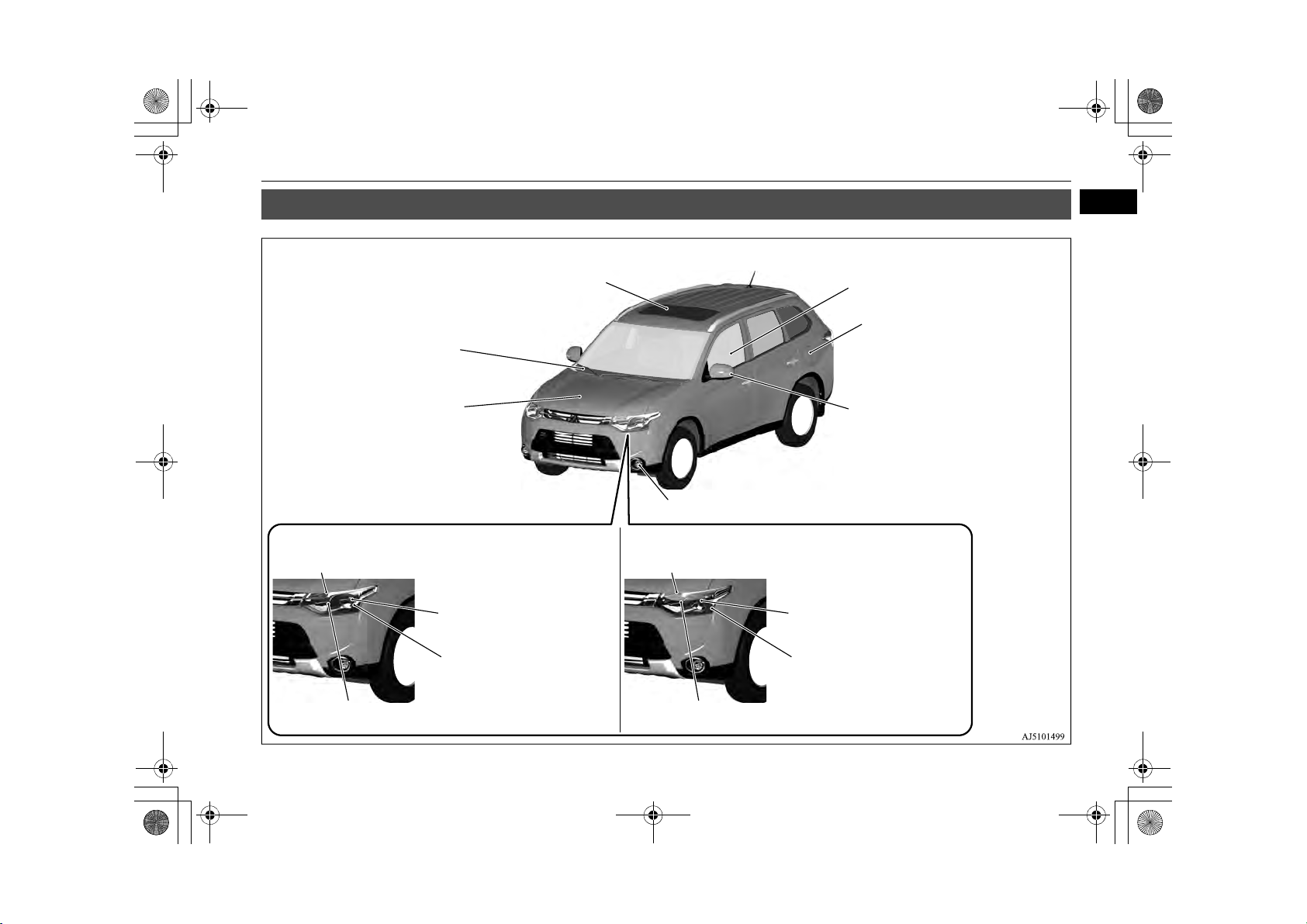
Side turn-signal lamps*
P. 6- 4 5, 11 - 22 , 11 -2 5
Front fog lamps P.6-46, 11-22, 11-26
Front turn-signal lamps P.6-45, 11-22, 11-25
Headlamps, low beam P.6-42,
11-22, 11-23
Position lamps P.6-40, 11-22, 11-24
Headlamps, high beam
P. 6 - 4 2, 1 1 - 2 2 , 1 1 - 2 4
Headlamps, high beam
P. 6- 4 2 , 11 - 2 2, 11 - 24
Position lamps P.6-40, 11-22, 11-24
Headlamps, low beam P.6-42,
11-22, 11-23
Front turn-signal lamps P.6-45, 11-22, 11-25
Electric window control P.4-29
Fuel tank filler P.2-13
Wind screen wipers P. 6-4 7
Bonnet P.11-3
Sunroof* P.4-31
Except for high intensity discharge headlamp type High intensity discharge headlamps type
BK0203201EN.book 6 ページ 2013年11月19日 火曜日 午前11時50分
Outside (Front)
Outside (Front)
1
E00100506751
Overview 1-6
Page 9
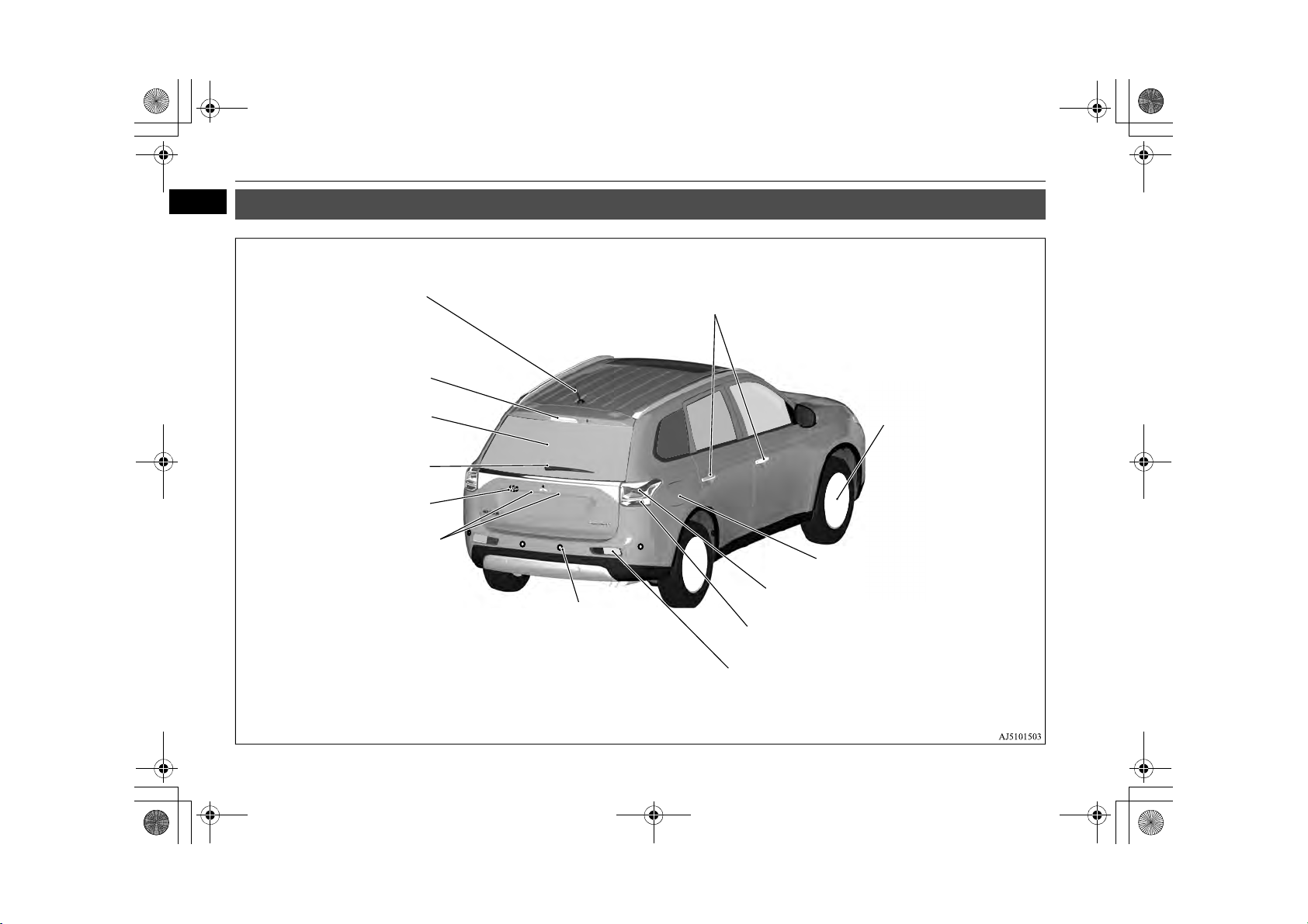
Antenna P.8-40
High-mounted stop lamp P.11-22
Rear window wiper
P. 6- 5 1
Rear view camera*
P. 7 - 6 7
Licence plate lamps
P.11-22, 11-28
Reversing lamps (passenger’s side)
P. 11 - 22
Stop lamps/Tail lamps
P. 11 - 22 , 1 1- 2 7
Turn-si gna l lamps
P. 6- 4 5 , 11 - 22 , 11 - 27
Changing tyres P.9-14
Tyr e in fla tion pr essu res P.11 -10
Tyr e ro tati on P. 11-11
Tyr e ch ain s P. 11-1 2
Size of tyres and wheels P.12-8
Keyless entry system P.4-3
Keyless operation system P.4-6
Locking and unlocking the doors P.4-14
Tai lgat e P.4- 16
Electric tailgate P.4-17
Charging lid P.3-10
Charging port courtesy lamp P.3-9
Reversing sensor system
BK0203201EN.book 7 ページ 2013年11月19日 火曜日 午前11時50分
Outside (Rear)
1
Outside (Rear)
E00100506764
1-7 Overview
Page 10
BK0203201EN.book 1 ページ 2013年11月19日 火曜日 午前11時50分
General information
Plug-in Hybrid EV System ..............................................................2-2
Cautions and actions to deal with intense heat ................................2-8
Cautions and actions to deal with intense cold ................................2-9
Fuel selection ..................................................................................2-12
Filling the fuel tank.........................................................................2-13
Installation of accessories ...............................................................2-14
Modification/alterations to the electrical or fuel systems ...............2-15
Genuine Parts..................................................................................2-15
Safety and disposal information for used engine oil ......................2-15
Do not carry fuel-filled containers or
spray cans inside your vehicle ....................................................2-16
Tak in g yo ur v eh ic le o ve rs eas .... .. .. .. .... .. .. .. .... .. .. ..... .. ..... .. .. .... .. .. .... .. 2- 16
2
Page 11
BK0203201EN.book 2 ページ 2013年11月19日 火曜日 午前11時50分
Plug-in Hybrid EV System
Plug-in Hybrid EV System
2
Main features
It is operated as electric vehicle in the EV
drive mode using the electrical power stored
in the drive battery,*
remaining amount of the drive battery. It is
also automatic control*
hybrid mode or parallel hybrid mode using
engine power from EV drive mode according
to the driving condition or if the charging
level of the drive battery is decreased.
If there is a remaining amount in the
*1:
drive battery, it is actively driven in the
EV drive mode. The cruising range varies depending on the remaining charge in
the drive battery, vehicle speed, and air
conditioner operating conditions.
2
Yo u c a n a d j us t th e ti m i ng t o s w it c h to
*
:
the EV drive mode by using the battery
save switch. Refer to “Battery save
switch” on page 7-22.
1
according to the
2
for driving in series
E00203500025
E00203600026
With the high performance motor, noise
and vibration during driving are greatly
limited and powerful acceleration can also
be obtained.
With the regenerative brake, the dr ive ba t-
tery is automatically charged when the
accelerator is released.
The vehicle can be charged from EV
charge power outlets (rated AC 240 V).
EV drive mode
The vehicle is driven by the motors only
using electrical power stored in the drive
battery. However, EV drive mode is cancelled depending on the drive battery
level, vehicle speed, and air conditioner
operating conditions. Pay attention to the
following points:
•Check the EV cruising range in the
information screen. Refer to “EV cruising range display/Total cruising range
display” on page 6-13.
•Drive your vehicle at moderate speeds
avoiding quick acceleration/deceleration. Repeated quick acceleration/deceleration causes the drive battery level to
decrease quickly, which extremely
reduces the EV cruising range.
Series hybrid mode
The vehicle is driven by the motors only
using the electricity generated by the
engine. This mode is used when the drive
battery level is low, at quick acceleration,
or when power is required like climbing
uphill.
Parallel hybrid mode
The vehicle is driven by the power of the
engine, assisted by motors. This mode is
used during high-speed driving with better engine efficiency.
2-2 General information
Page 12
BK0203201EN.book 3 ページ 2013年11月19日 火曜日 午前11時50分
The roles of the motors and engine in each drive mode
Plug-in Hybrid EV System
Motor Engine Driving conditions
EV Drive Mode ON OFF Driving on streets and commuting
Series Hybrid Mode ON Generates electricity
Parallel Hybrid Mode ON
Drivers front wheels and generates
electricity
Powerful acceleration uphill road
such as mountain road
High-speed driving
Regenerative braking
Motion energy is converted into electric energy using the motor as a power generator.
Then a braking force generates and converted electric energy will be charged to the drive battery.
If you lift your foot off the accelerator pedal during driving, a braking force that equivalent to engine braking of a combustion engine vehicle
will be generated. Also, if you shift the select position into “B” (BRAKE) from “D” (DRIVE), effectiveness of the regenerative braking is getting strong. Shift the selector lever into “B” (BRAKE) position according to the driving condition.
Regenerative brake force increases with the foot brake force when the brake pedal is depressed.
If a problem occurs in the Plug-in hybrid EV system, or if the ABS and/or the ASC have been activated, the regenerative braking will be
restricted. The foot brake will still operate.
Operation of gasoline engine
E00203700027
Even when the vehicle is driving in EV
drive mode, it may be automatically
changed to series hybrid mode or parallel
hybrid mode in the following cases:
•The plug-in hybrid EV system is too hot
or too cold.
•Quick acceleration is applied.
•The air conditioner is operating.
•The accelerator pedal is depressed hard
on an uphill road or expressway.
•In cold weather
•The vehicle has not been refueled for a
long time.
•The drive battery level is low.
In addition to the above, there are more
cases where EV drive mode is automatically changed to series or parallel hybrid
mode.
Even while the vehicle is stopped, the
engine may automatically be started in the
following cases:
•The drive battery level is low.
2
General information 2-3
Page 13
CAUTION
WARNING
WARNING
BK0203201EN.book 4 ページ 2013年11月19日 火曜日 午前11時50分
Plug-in Hybrid EV System
•The plug-in hybrid EV system is too hot
or too cold.
2
•The air conditioner is used.
•The vehicle has not been used for a long
time.
•The engine has not been operated for a
long time.
Refueling (gasoline)
If the warning display appears, refuel as
soon as possible.
If the vehicle is runs out of fuel, the
engine will not start even in a situation
need to be generated electricity, the following conditions will occur.
•The driving performance falls (since
only the electrical power stored in the
drive battery can be used for the driving).
•The heating performance cannot be
available (except vehicles with electric
heater).
•The effectiveness of the heater is insufficient (vehicles with electric heater).
•The catalytic converter may be damaged
due to excessive high temperature.
Refer to “Filling the fuel tank” on page 2-13.
Refer to “Fuel remaining display screen” on
page 6-9.
E00203800028
Depending on the operating conditions of
your vehicle, the fuel in the fuel tank may
not be used for a long time and stay in the
tank, resulting in deterioration of the fuel
quality. As this may affect the engine and
fuel system parts, observe the following
instructions:
•Run the engine by pressing the battery
charge switch at least once in 3 months.
Refer to “Battery charge switch” on page
7-23.
• Refuel 20 litres or more of fuel every 6
months (to make the total refueling amount
in 6 months be 20 litres or more).
If refueling of the above amount is not possi-
ble due to a high fuel level because the vehicle has not been used for a long time or for
some other reason, consult a MITSUBISHI
MOTORS Authorised Service Point.
Drive battery
A sealed lithium ion high voltage battery
(drive battery) is adopted for Outlander
PHEV. If the drive battery is disposed of
improperly, there is a risk of severe burns
and electrical shock that may result in
serious injury or death and there is also a
risk of environmental damage.
E00203900029
Never attempt to use the drive battery for
any other purpose.
It is the battery to operate the motor and
the air conditioning.
In addition to the drive battery, Outlander
PHEV has the auxiliary battery to operate
lamps, wipers, etc.
Compact, light-weight lithium ion battery
with high energy density is used for the
drive battery.
The drive battery has the following char-
acteristics.
Please read this carefully paying attention
to the following:
Characteristics
The same as ordinary lithium-ion batter-
ies, the battery capacity of the drive battery gradually reduces with time, resulting
in reduced cruising range. Depending on
the usage conditions, such as frequent
quick acceleration/deceleration,
extremely hot weather, storing the vehicle
in high ambient temperatures, etc., the
rate of battery capacity drop will increase.
2-4 General information
Page 14
WARNING
WARNING
BK0203201EN.book 5 ページ 2013年11月19日 火曜日 午前11時50分
The performance may be changed due to
the outside temperature.
At low temperature, in particular, the EV
cruising range is short and the charging
time is long, compared to operation at
normal temperature.
The battery is gradually discharged with-
out use and the battery charge is lowered.
It is not necessary to consume the battery
completely before charging.
EV cruising range
Even if the charge level is the same, the
EV cruising range may vary depending on
driving conditions. Since driving at high
speed or climbing on a hill requires higher
consumption of the drive battery than
usual, the EV cruising range is shortened.
Since the air conditioning (cooling or
heating) consumes power of the drive battery, its operation results in a shorter EV
Precautions for operation
If your vehicle is not used for a long time,
check the drive battery level display every
3 months.
If the drive battery level display shows 0,
charge the battery until some indication
appears. Alternately, put the operation
cruising range. Maintain an appropriate
temperature.
Put the selector lever to “B” (BRAKE)
position according to the road condition.
To charge the drive bat ter y wi th a ppr opr iate use of the regenerative brake, it can be
increased the EV cruising range.
mode of the power switch in “ON” to start
the engine automatically, wait for the
engine to stop automatically, then put the
Acoustic Vehicle Alerting System (AVAS)
operation mode of the power switch in
“OFF”.
Mitsubishi Motors collects drive batteries.
If you scrap your vehicle, please consult a
Mitsubishi Motors Authorised Service
Point.
The Acoustic Vehicle Alerting System
(AVAS) is device that uses sound to alert
pedestrians of the presence of the vehicle.
The system operates when the vehicle speed
is about 35 km/h or less and the engine is not
running.
Refer to “Acoustic Vehicle Alerting System
(AVAS)” on page 7-24.
E00204000027
E00204100028
Plug-in Hybrid EV System
Even if the Acoustic Vehicle Alerting Sys-
tem (AVAS) sounds, pay special attention
to pedestrians.
Pedestrians may not notice the oncoming
vehicle, which may cause an accident
resulting in serious personal injury or
death.
In case of a collision
E00204200029
A crash or impact significant enough to
require an emergency response for conventional vehicles would also require the same
response for Outlander PHEV.
Also follow the instructions described below
to avoid severe burns and electrical shock that
may result in serious injury or death.
If your vehicle is drivable, pull your vehi-
cle off the road to a safe, nearby location
and remain on the scene.
Also, if possible, do the following operations and stay out of the way of any
oncoming traffic while awaiting the
arrival of emergency responders.
•Apply chocks to the wheels.
•Put the select position in “P”(PARK)
position.
•Apply the parking brake.
2
General information 2-5
Page 15
WARNING
WARNING
WARNING
BK0203201EN.book 6 ページ 2013年11月19日 火曜日 午前11時50分
Plug-in Hybrid EV System
2
•Open the windows, doors and tailgate.
•Put the operation mode in OFF.
•Turn on the hazard warning flashers.
• Move the key away from the vehicle to
prevent unintended start-up of the system by inadvertent contact with a switch
or impact from the crash.
Never touch high-voltage wiring, connec-
tors, and other high-voltage parts, such as
the inverter unit and drive battery. An
electric shock may occur if exposed electric wires are visible when viewed from
inside or outside of your vehicle. For their
locations, see “High-voltage components”
on page 2-7.
If the vehicle receives a strong impact to
the floor while driving, stop the vehicle in
a safe place and check the floor.
Never start the plug-in hybrid EV system
if you found the leak of a liquid (except
water of the air conditioner) while checking the outside of the vehicle because there
is possibility the fuel system has been
damaged and causing of fire or exploding.
In such case, immediately contact your
MITSUBISHI MOTORS Authorized Service Point.
Leaks or damage to the drive battery may
result in a fire. If you discover them, contact emergency services immediately.
Since the fluid leak may be lithium manganite from the Lithium-ion battery, never
touch any fluid leaking from the inside or
outside of the vehicle. If the fluid contacts
your skin or eyes, wash it off immediately
with a large amount of water and receive
immediate medical attention to help avoid
serious injury.
If you are unable to safely assess the vehi-
cle due to vehicle damage, do not touch
the vehicle. Leave the vehicle and contact
emergency services. Advise emergency
responders that this is a Plug-in Hybrid
vehicle.
If a fire occurs in this vehicle, leave the
vehicle as soon as possible and contact
emergency services. Do not attempt to
extinguish a fire by yourself. If the fire
involves a lithium-ion battery, it will
require large, sustained volumes of water
for extinguishment. Using a small amount
of water or the incorrect fire extinguisher
can result in serious injury or death from
electrical shock.
When you leave the vehicle, if possible,
open the windows, doors and tailgate to
prevent accumulation of poisonous/combustible gasses. This will also assist in the
rescue and fire fighting process.
As with any vehicle fire, the byproducts of
combustion can be toxic. Do not inhale
smoke, vapors, or gas from the vehicle.
Move to a safe distance upwind and uphill
from the vehicle fire and out of the way of
any oncoming traffic while awaiting the
arrival of emergency responders.
If you detect leaking fluids, sparks, smoke,
flames, gurgling, popping or hissing noises
originating from the high voltage battery
compartment, contact emergency services
immediately. This may result in a fire.
Physical damage to the vehicle or high
voltage battery may result in immediate or
delayed release of toxic and/or flammable
gases and fire.
If your vehicle needs to be towed, trans-
port the vehicle on a flatbed truck or tow
the vehicle with all wheels off the ground.
If the any wheels are on the ground when
towing, this may cause damage to the electric motors. This may also cause a fire, if
wiring in the electric motor unit room
becomes damaged. Refer to “Towing” on
page 9-19.
Do not attempt to repair a damaged Plug-
in Hybrid vehicle by yourself. Please contact a MITSUBISHI MOTORS Authorised Service Point for service.
2-6 General information
Page 16
NOTE
WARNING
WARNING
BK0203201EN.book 7 ページ 2013年11月19日 火曜日 午前11時50分
Plug-in Hybrid EV System
In the event of an accident that requires
body repair and painting, the vehicle
should be delivered to a MITSUBISHI
MOTORS Authorised Service Point to
have the drive battery and high voltage
parts such as the inverter, including the
attached wiring harness, removed prior to
painting. If exposed to heat in the paint
booth, the drive battery will experience
battery capacity loss.
A damaged drive battery can also pose
safety risks to untrained mechanics and
repair personnel.
The emergency shut-off system will be acti-
vated and the high-voltage system will automatically turn off under the following
conditions:
•Certain front, side or rear collisions.
•Certain Plug-in Hybrid EV system malfunctions.
When the emergency shut-off system is acti-
vated, the ready indicator is turned off. Refer
to “Indicator and warning lamps” on page
6-21.
If the emergency shut-off system activates,
contact a MITSUBISHI MOTORS Authorised Service Point.
Inspection and maintenance
E00204300020
When performing inspection and maintenance, be careful in the following points.
Before performing inspection or mainte-
nance, be sure to disconnect the charge
connector from the vehicle and confirm
that put the operation mode of the power
switch in “OFF”.
Never touch, disassemble, remove or
replace highvoltage parts, exposed electrical components, cables or connectors.
Failure to follow this instruction can
result in severe burns or electric shock
causing serious injury or death. High-voltage cables are colored orange. The vehicle
high voltage system has no user serviceable parts. Take your vehicle to a MITSUBISHI MOTORS Authorised Service Point
for any necessary maintenance.
Never touch the service plug under the
rear seat. Improper handling of this could
cause an electric shock which result in a
serious injury or death. The service plug is
used to shut off the high voltage from the
drive battery when repairing the vehicle
at a MITSUBISHI MOTORS Authorised
Service Point.
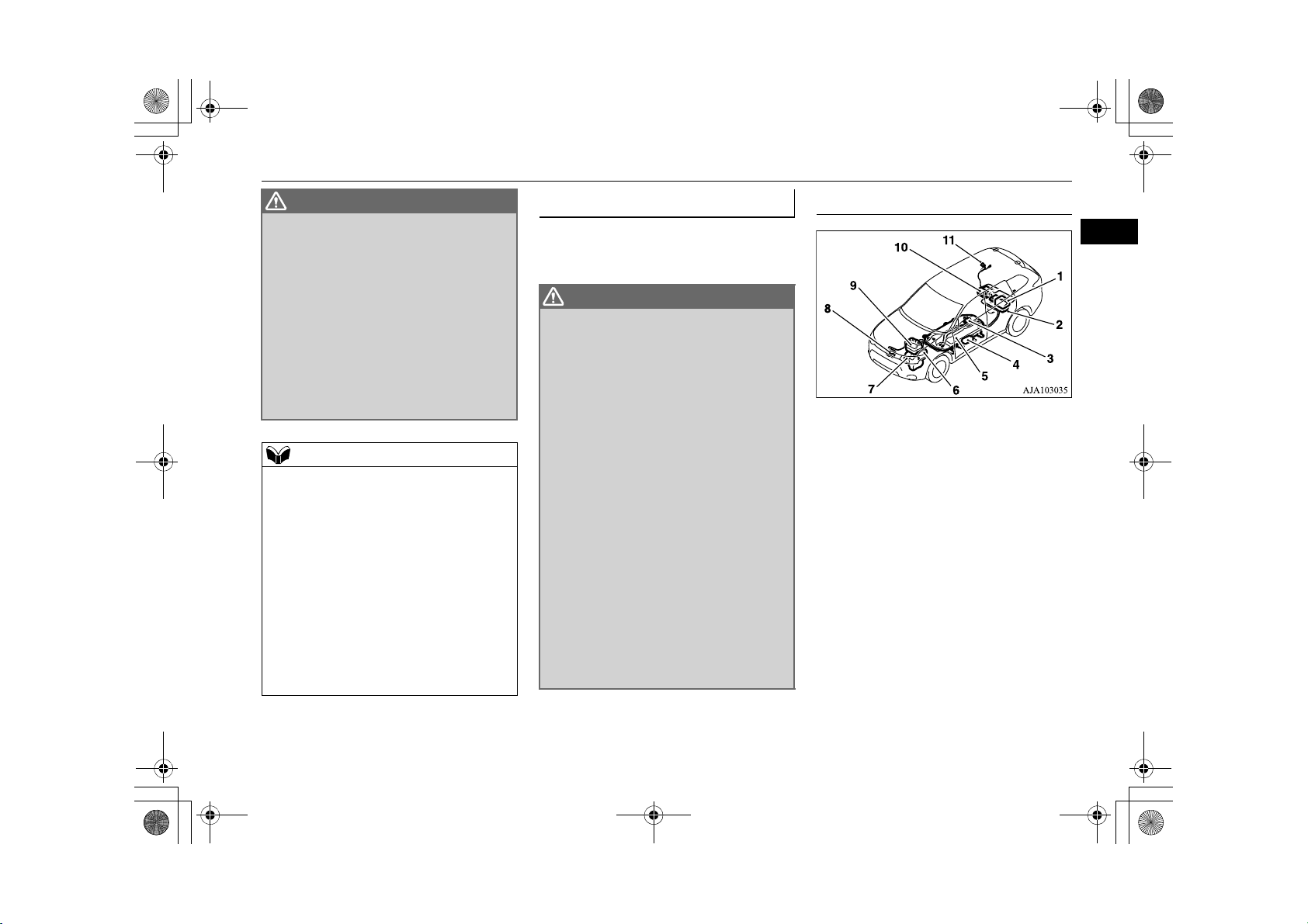
High-Voltage components
2
1- On board charger/DC-DC converter
2- Rear motor
3- Service plug
4- Electric heater*
5- Drive Battery
6- Front motor
7- Generator
8- Air conditioner compressor
9- Power drive unit (PDU)
10- Rear electric motor control unit (MCU)
11- Charge port
General information 2-7
Page 17
WARNING
WARNING
WARNING
BK0203201EN.book 8 ページ 2013年11月19日 火曜日 午前11時50分
Cautions and actions to deal with intense heat
For persons with electro-medi-
The Plug-in Hybrid EV System uses high
2
voltage up to DC 300 volt. The system can
be hot during and after starting and when
the vehicle is shut off. Be careful of both
the high voltage and the high temperature.
Follow the warning labels that are
attached to the vehicle.
Always assume the high voltage battery
and associated components are energized
and fully charged.
Never perform servicing when READY
indicator is illuminating or when the
charging indicator is illuminating or flashing because the high-voltage system is
operating.
cal apparatus such as implantable cardiac pacemaker or
implantable cardioverter-defibrillator
Do not bring your body close to the foot
area of the rear seat and do not stay in the
luggage compartment while the vehicle is
moving. Also, do not allow persons using
an electro-medical apparatus to stay in the
luggage compartment while the vehicle is
moving. The operation of electro-medical
apparatus may be affected.
Before you perform charging work, ask
the manufacturer of your electro-medical
apparatus about the effect from charging
work. Charging may affect the operation
of your electro-medical apparatus.
Refer to “Normal charging (charging
method with rated AC 240 V outlet)” on
page 3-8.
E00204400021
Observe the following precautions for nor-
mal charging:
•Keep away from the charge connector or
control box.
•Do not stay inside of the vehicle.
•Do not get in the vehicle (including the
luggage comapartment) to take out
something or for other purpose.
Refer to “Normal charging (charging
method with rated AC 240 V outlet)” on
page 3-8.
Cautions and actions to deal with intense heat
E00203001069
When the ambient temperature is approximately 45 °C or higher, the phenomena described below may occur. Please take the described action.
2-8 General information
Page 18
NOTE
BK0203201EN.book 9 ページ 2013年11月19日 火曜日 午前11時50分
Cautions and actions to deal with intense cold
Even if the ambient temperature is approximately 45 °C or lower, when driving at high-speed and uphill repeatedly, the phenomena described
below may occur. Please take the described actions.
Approx. ambi-
ent temperature
• The motor output is restricted and the vehicle performance may
Approx. 45 °C or
higher
*: Refer to “Limited driving mode warning display” on page 6-33. Display of the limited driving mode warning display does not indicate a malfunction.
Startup and driving
Charging and battery
be decreased. Then, the limited driving mode warning display*
may be displayed.
•Charging time becomes longer, charging may not be possible or
it may stop on the way.
Phenomena Corrective action
•Stop the vehicle at a safe
place if needed with the plugin hybrid EV system started.
•Park in a well-ventilated,
shady place.
Cautions and actions to deal with intense cold
When the ambient temperature is approximately -15 °C or lower, the phenomena described below may occur. Please take the described cor-
rective action.
2
E00203101073
General information 2-9
Page 19
BK0203201EN.book 10 ページ 2013年11月19日 火曜日 午前11時50分
Cautions and actions to deal with intense cold
Approx. ambi-
ent temperature
2
Approx. -15 °C
or lower
Startup and driving
Charging and battery••
Phenomena Corrective action
•The motor output is restricted and the vehicle performance may
be decreased. Then, the limited driving mode warning display*
may be displayed.
•Regenerative braking performance may decrease. •When braking, depress the
Charging time becomes longer.
Complete charging may not be possible.
•Keep driving if you can drive
1
at a similar speed as surrounding vehicles.
If you cannot drive at a similar speed as surrounding vehicles, stop the vehicle at a safe
place and charge the drive
battery.
brake pedal harder.
•When you have finished driving, charge the drive battery
before its temperature falls.
2-10 General information
Page 20
CAUTION
BK0203201EN.book 11 ページ 2013年11月19日 火曜日 午前11時50分
Cautions and actions to deal with intense cold
Approx. ambi-
ent temperature
•The Plug-in Hybrid EV system may not be started. Then, blink-
ing of the ready indicator*
COLD” may be displayed on the multi information display.
Startup and driving
Approx. -30 °C
or lower
• The vehicle performance may be restricted and the normal driving may become impossible. Then, “BATTERY TOO COLD”
may be displayed.
• Regenerative braking performance may decrease or lose. • When braking, depress the
•Charging may become impossible or it may stop on the way. •In the daytime, wait for the
Charging and battery
“BATTERY TOO COLD” is displayed, contact a MITSUBISHI MOTORS Authorized Service Point.
Blinking of the ready indicator*2 continues and “BATTERY TOO COLD” is displayed on the multi information display with vehicle conditions, the drive
battery can not be warm up.
Phenomena Corrective action
2
may continue and “BATTERY TOO
••In the daytime, wait for the
temperature to rise, restart the
plug-in hybrid EV system.
On vehicles equipped with
both MITSUBISHI Remote
control and electric heater, if
low temperature is predicted,
even if the drive battery is full
charge, connect EV charging
cable beforehand.
The drive battery is automati-
cally warmed up*
•Stop the vehicle at a safe
place immediately.
brake pedal harder.
temperature to rise, restart the
plug-in hybrid EV system.
3
.
2
General information 2-11
Page 21
NOTE
CAUTION
CAUTION
CAUTION
BK0203201EN.book 12 ページ 2013年11月19日 火曜日 午前11時50分
Fuel selection
*1: Refer to “Limited driving mode warning display” on page 6-33.
2
Display of the Limited driving mode warning display does not indicate a malfunction.
2
*
: Refer to “ready indicator” on page 6-37.
3
: To make warm up the drive battery, you should perform to communicate with the wireless LAN device (which conforms to IEEE 802.11 b and supports
*
iOS or Android) for MITSUBISHI Remote Control to the vehicle. If the information of “” mark on the wireless LAN device is displayed, connect the
EV charging cable as soon as possible.
Refer to “MITSUBISHI Remote Control” on page 3-17.
If the warming up of the drive battery is activated during home or public charging device (EVSE: Electric Vehicles Supply Equipment) charging, the
charging and warming up of the drive battery may be stopped.
While warm up the drive battery, the following phenomena may occur.
• The operation sound of on board equipment and the state of charge is displayed on the multi information display.
Refer to “Charging from rated AC 240V outlet” on page 3-10.
• Inside of the vehicle may be heated automatically.
•The drive battery may not become full charge, or the remaining capacity of drive battery may decrease.
Fuel selection
E00200104259
Recommended
fuel
Yo u r v e hi cl e h as a f ue l f il le r t ub e sp ec i al ly
2-12 General information
Unleaded petrol octane number
90 RON or higher
designed to accept the smaller diameter
unleaded fuel dispensing nozzles only.
Liquid Petroleum Gas (L.P.G.)
Yo ur v e hi cl e c a nn ot be r u n o n L. P. G.
Use of an L.P.G. fuel conversion may result
in significant damage to your vehicles fuel
system, engine, engine sensors and exhaust
system.
Ethanol
A mixture of up to 10 % ethanol (grain alcohol) and 90 % unleaded petrol may be used in
your vehicle, provided the octane number is
at least as high as that recommended for
unleaded petrol.
Do not use more than 10 % concentration of
ethanol (grain alcohol) by volume.
Use of more than 10 % concentration may
lead to damage to your vehicle fuel system,
engine, engine sensors and exhaust system.
Do not operate your vehicle on gasoline con-
taining methanol. Using this type of alcohol
could adversely affect the vehicle’s performance and damage critical parts of the vehicle’s fuel system.
Page 22
NOTE
WARNING
WARNING
CAUTION
BK0203201EN.book 13 ページ 2013年11月19日 火曜日 午前11時50分
Filling the fuel tank
Poor quality petrol can cause problems such
as hard starting, stalling, engine noise and
hesitation. If your experience these problems, try another brand and/or grade of petrol.
If the check engine warning lamp flashes,
have the system checked as soon as possible
at a MITSUBISHI MOTORS Authorised
Service Point.
Filling the fuel tank
E00200203572
When handling fuel, comply with the
safety regulations displayed by garages
and filling stations.
Gasoline is highly flammable and explo-
sive. You could be burned or seriously
injured when handling it. When refueling
your vehicle, always put the operation
mode of the power switch in OFF and
keep away from flames, sparks, and smoking materials. Always handle fuel in wellventilated outdoor areas.
Before removing the fuel cap, be sure to
get rid of your body’s static electricity by
touching a metal part of the car or fuel
pump. Any static electricity on your body
could create a spark that ignites fuel
vapor.
Perform the whole refueling process
(opening the fuel tank filler door, removing the fuel cap, etc.) by yourself. Do not
let any other person come near the fuel
tank filler. If you allowed a person to help
you and that person was carrying static
electricity, fuel vapor could be ignited.
Do not perform charging and refueling at
the same time. If you charged with static
electricity, fuel vapor could be ignited by
the discharge spark.
Do not move away from the fuel tank filler
until refueling is finished. If you moved
away and did something else (for example,
sitting on a seat) part-way through the
refueling process, you could pick up a
fresh charge of static electricity.
Be careful not to inhale fuel vapor. Fuel
contains toxic substances.
Keep the doors and windows closed while
refueling the vehicle. If they were open,
fuel vapor could get into the cabin.
If the tank cap must be replaced, use only
a MITSUBIHI MOTORS original part.
Depending on the operating conditions of
your vehicle, the fuel in the fuel tank may
not be used for a long time and stay in the
tank, resulting in deterioration of the fuel
quality. As this may affect the engine and
fuel system parts, observe the following
instructions:
•Run the engine by pressing the battery
charge switch at least once in 3 months.
Refer to “Battery charge switch” on page
7-23.
• Refuel 20 litres or more of fuel every 6
months (to make the total refueling amount
in 6 months be 20 litres or more).
If refueling of the above amount is not possi-
ble due to a high fuel level because the vehicle has not been used for a long time or for
some other reason, consult a MITSUBISHI
MOTORS Authorised Service Point.
Fuel tank capacity
45 litres
Refuelling
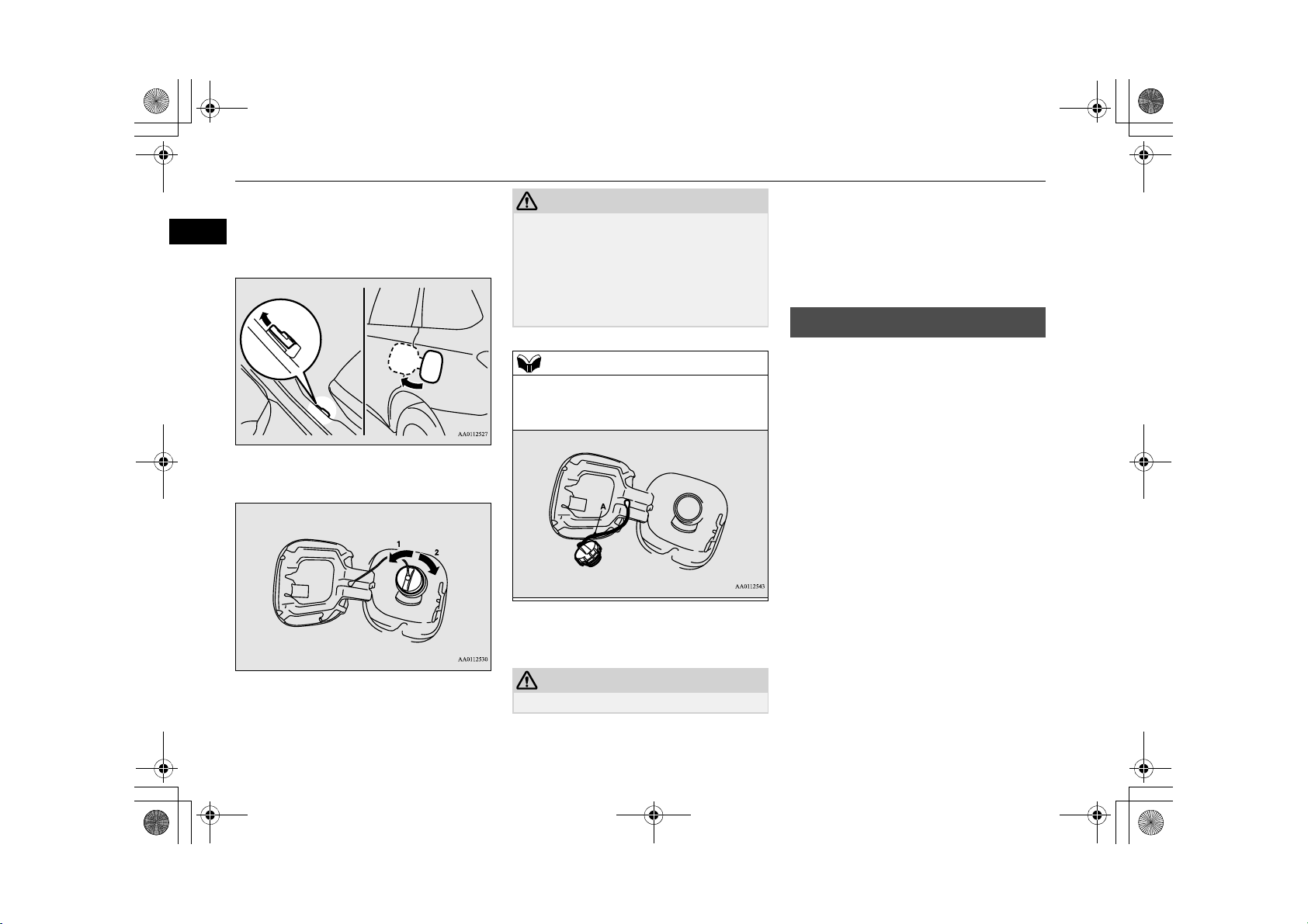
1. Before filling with fuel, stop the plug-in
hybrid EV system.
2
General information 2-13
Page 23
CAUTION
NOTE
CAUTION
BK0203201EN.book 14 ページ 2013年11月19日 火曜日 午前11時50分
Installation of accessories
2. The fuel tank filler is located on the rear
left side of your vehicle.
2
Open the fuel tank filler door with the
release lever located the side of the
driver’s seat.
3. Open the fuel tank filler tube by slowly
turning the cap anticlockwise.
1- Remove
2- Close
Since the fuel system may be under pressure,
remove the fuel tank filler tube cap slowly.
This relieves any pressure or vacuum that
might have built up in the fuel tank. If you
hear a hissing sound, wait until it stops
before removing the cap. Otherwise, fuel
may spray out, injuring you or others.
While filling with fuel, hang the fuel cap on
the hook (A) located on the inside of the fuel
tank filler door.
4. Insert the gun in the tank port as far as it
goes.
Do not tilt the gun.
5. When the gun stops automatically, do not
fill with fuel any more.
6. To close, turn the fuel cap slowly clockwise until you hear clicking sounds, then
gently push the fuel tank filler door
closed.
Installation of accessories
E00200300963
We r ec ommen d you t o con su lt yo ur
MITSUBISHI MOTORS
Authorised Service Point.
The installation of accessories, optional
components, etc., should only be carried
out within the limits prescribed by law in
your country, and in accordance with the
guidelines and warnings contained within
the documents accompanying this vehicle.
Installing electric components incorrectly
could lead to a fire. See the “Modification/alterations to the electrical or fuel
systems” section within this owner’s manual.
Using a cellular phone or radio set inside
the vehicle without an external antenna
may cause electrical system interference,
which could lead to unsafe vehicle operation.
2-14 General information
Page 24
CAUTION
WARNING
BK0203201EN.book 15 ページ 2013年11月19日 火曜日 午前11時50分
Tyre s a nd whe els wh ich do no t m eet sp ec-
ifications must not be used.
Refer to the “Specifications” section for
information regarding wheel and tyre
sizes.
Important points!
Due to large number of accessory and
replacement parts of different manufactures
available in the market, it is not possible, not
only for MITSUBISHI MOTORS, but also a
MITSUBISHI MOTORS Authorised Service
Point, to check whether the attachment or
installation of such parts affects the overall
safety of your MITSUBISHI-vehicle.
Even when such parts are officially authorised, for example by a “general operators permit” (an appraisal for the part) or through the
execution of the part in an officially approved
manner of construction, or when a single
operation permit following the attachment or
installation of such parts, it cannot be
deduced from that alone, that the driving
safety of your vehicles has not been affected.
Consider also that there basically exists no
liability on the part of the appraiser or the
official. Maximum safety can only be ensured
with parts recommended, sold and fitted or
installed by a MITSUBISHI MOTORS
authorised Service Point (MITSUBISHI
MOTORS GENUINE replacement parts and
MITSUBISHI MOTORS accessories). The
same also pertains to modifications of
MITSUBISHI vehicles with respect to the
production specifications. For safety reasons,
do not attempt any modifications other than
those that follow the recommendations of a
MITSUBISHI MOTORS authorised Service
Point.
Modification/alterations to
the electrical or fuel systems
MITSUBISHI MOTORS CORPORATION
has always manufactured safe, high quality
vehicles. In order to maintain this safety and
quality, it is important that any accessory that
is to be fitted, or any modifications carried
out which involve the electrical or fuel systems, should be carried out in accordance
with MITSUBISHI guidelines.
If the wires interfere with the vehicle body or
improper installation methods are used (protective fuses not included, etc.), electronic
devices may be adversely affected, resulting
in a fire or other accident.
Modification/alterations to the electrical or fuel systems
Genuine Parts
E00200500499
MITSUBISHI MOTORS has gone to great
lengths to bring you a superbly crafted automobile offering the highest quality and
dependability.
Use MITSUBISHI MOTORS GENUINE
Parts, designed and manufactured to maintain
your MITSUBISHI MOTORS automobile at
top performance. MITSUBISHI MOTORS
GENUINE Parts are identified by this mark
and are available at all MITSUBISHI
MOTORS Authorised Service Points.
E00200400368
Safety and disposal information for used engine oil
E00200600155
Prolonged and repeated contact may
cause serious skin disorders, including
dermatitis and cancer.
Avo id contac t w ith th e s kin as fa r a s poss i-
ble and wash thoroughly after any contact.
2
General information 2-15
Page 25
WARNING
WARNING
BK0203201EN.book 16 ページ 2013年11月19日 火曜日 午前11時50分
Do not carry fuel-filled containers or spray cans inside your vehicle
Tak ing you r veh icl e ov erse as
Keep used engine oils out of reach of chil-
2
dren.
Protect the environment
It is illegal to pollute drains, water courses
and soil. Use authorised waste collection
facilities, including civic amenity sites and
garages providing facilities for disposal of
used oil and used oil filters. If in doubt, contact your local authority for advice on disposal.
Do not carry fuel-filled containers or spray cans inside
your vehicle
E00201000013
Leaving fuel-filled containers or spray
cans in your vehicle could cause the containers to burst or an explosion of evaporated gas.
MITSUBISHI MOTORS from time to time
receives enquiries regarding shipping of vehicles overseas.
The enquiries mainly fall into the following
categories:
Private individuals wishing to take their
locally purchased vehicle overseas.
Private individuals wishing to purchase an
export specification (e.g. left hand drive)
vehicle here in Australia and take it overseas.
Commercial enquiries wishing to arrange
the export of MITSUBISHI MOTORS
vehicles to an associated or client company.
MITSUBISHI MOTORS advises the following:
Different countries have different vehicle regulations, fuel standards, driving conditions
and customer preferences.
A vehicle sold in several markets may look
outwardly similar but have very significant
differences.
Tak ing a v ehi cle b uil t to a n Aus tra lia n spe cification overseas therefore runs the risk of:
E00200800115
Non-compliance with local regulations.
Unsatisfactory vehicle performance.
Difficulties in after sales service.
Parts unavailable.
Diminished resale value.
We be li eve th e p ra ct ice to be un econ om ic a nd
strongly recommend against it.
2-16 General information
Page 26
BK0203201EN.book 1 ページ 2013年11月19日 火曜日 午前11時50分
Charging
Charging ..........................................................................................3-2
Battery ..............................................................................................3-3
Basic knowledge for charging .........................................................3-3
EV charging cable ............................................................................ 3-5
Normal charging (charging method with rated AC 240 V outlet) ...3-8
Charging troubleshooting guide ....................................................3-15
MITSUBISHI Remote Control*.....................................................3-17
3
Page 27
BK0203201EN.book 2 ページ 2013年11月19日 火曜日 午前11時50分
Charging
Charging
Yo ur ve hic l e i s e qu i pp ed wit h a c har g e p or t a nd a ch a rg in g c a bl e ( EV ch a rg in g c a bl e) fo r ch a rg in g w i th a A C 2 40 V o u tl et . You can also charge
3
your vehicle using 240V home or public charging device (EVSE*
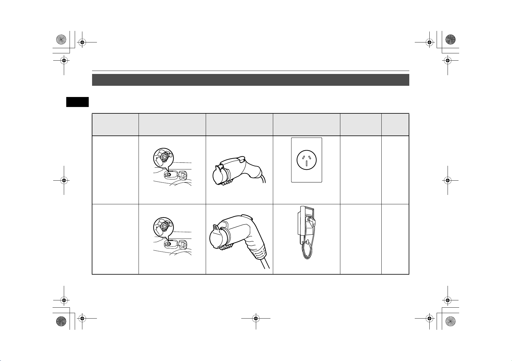
Category Charge port Charge connector Charging Source
Normal charging
(AC 240V)
When using a gen-
uine charging cable
Right rear side of vehicle
1
) compatible with Outlander PHEV.
240V household outlet (15
amp dedicated circuit
required)
Charging time
with fully dis-
charged battery
About 5 hours P.3-8
E08303801051
Reference
Normal charging
(AC 240V)
When using a
home or public
charging device
1
(EVSE*
)
Right rear side of vehicle
*1: EVSE = Electric Vehicle Supply Equipment
3-2 Charging
Home or public charging
device
240V/15A:
About 3.5
2
hours*
P. 3 - 8
Page 28
NOTE
NOTE
WARNING
BK0203201EN.book 3 ページ 2013年11月19日 火曜日 午前11時50分
*2: Use this time as a guide because the rated AC voltage and the rated current value may differ from country to country.
Alternately, the drive battery can be almost fully charged by turning on the battery charge switch while the vehicle is running or stopping.
Refer to “Battery charge switch” on pages 7-23.
Battery
E08300101037
There are two types of batteries installed in
your vehicle: a drive battery for operating the
motor (electric motor unit) and air conditioning as well as an auxiliary battery for starting
the Plug-in Hybrid EV system and operating
the lamps, wipers, etc.
This chapter explains charging of the drive
battery.
The auxiliary battery is automatically
charged while the ready indicator is illuminated or during charge for the drive battery.
Refer to “Ready indicator” on page 6-37.
If the auxiliary battery is flat, the Plug-in
Hybrid EV system cannot be started.
Refer to “Emergency starting” on page 9-2.
Basic knowledge for charging
E08300201070
Normal charging is performed through the on
board charger using rated AC 240 V outlet as
the power source
To redu ce th e ri sk o f el ec tr ic sh oc k o r fi re
due to electric leak, always use an outlet
protected by a residual current detector,
rated for amperage equal to or greater
than the value specified by MITSUBISHI
MOTORS, and that is connected to a dedicated branch circuit. If the circuit is
shared, and another electrical device is
being used at the same time the vehicle is
charging, the breaker may trip and the
circuit may cause adverse interference on
MCB (Moulded Circuit Board) and household electrical appliances such as TVs and
audio systems.
It is possible to charge even in rain or
snow. However, be sure to pay attention to
the following:
Battery
3
Charging 3-3
Page 29
WARNING
CAUTION
NOTE
WARNING
NOTE
BK0203201EN.book 4 ページ 2013年11月19日 火曜日 午前11時50分
Basic knowledge for charging
•Do not touch normal charging port, normal charge connector, outlet and plug
3
with wet hands.
•Keep away from water when connecting
the normal charging port, normal charge
connector, outlet and plug.
•Do not perform the charging in the out of
doors when heavy rain, heavy snow,
strong winds, and thunder, when a bad
weather is expected in the future.
If water goes into the normal charging
port or the normal charge connector, it
could cause a short circuit, a fire and an
electric shock.
Be sure closing completely the charging
lid and the inner lid and do not leave the
EV charging cable in an outdoors.
If the connected part of the charging plug
has been buried in snow while charging,
turn off the hand switch or the breaker
connected with the outlet first, then
remove the snow and disconnect the
charging plug. If your vehicle body has
been buried in snow while charging,
remove the snow and then disconnect the
charge connector.
When you perform the normal charging at
away from home, some normal chargers
may not correspond to your vehicle. Consult an administrator or a maker of the
normal charger that it corresponds to
your vehicle before using it. Also perform
normal charging according to the operating procedure indicated on the body of
normal charger.
Do not attempt to perform a jump start on the
auxiliary battery at the same time that the
drive battery is being charged. Doing so may
damage the vehicle or charging cable and
could cause an injury.
Refer to “Emergency starting” on page 9-2.
To mai nta in the c apa cit y o f t he dri ve bat ter y,
the following is recommended:
•Fully charge the vehicle in normal charging
every two weeks.
• Do not repeat charging near the full charge
level.
If your vehicle is not used for a long time,
check the energy level gauge every 3
months. If the gauge shows 0, charge the
drive battery until some indication appears.
Alternately, put the operation mode of the
power switch in “ON” to start the engine
automatically, wait for the engine to stop
automatically, then put the operation mode
of the power switch in “OFF”.
In the event of a electrical power outage
while charging, charging restarts automatically with the restoration of electricity.
3-4 Charging
Page 30
Indicator (LED) and button
E
G
F
H
I
C
B
A
D
BK0203201EN.book 5 ページ 2013年11月19日 火曜日 午前11時50分
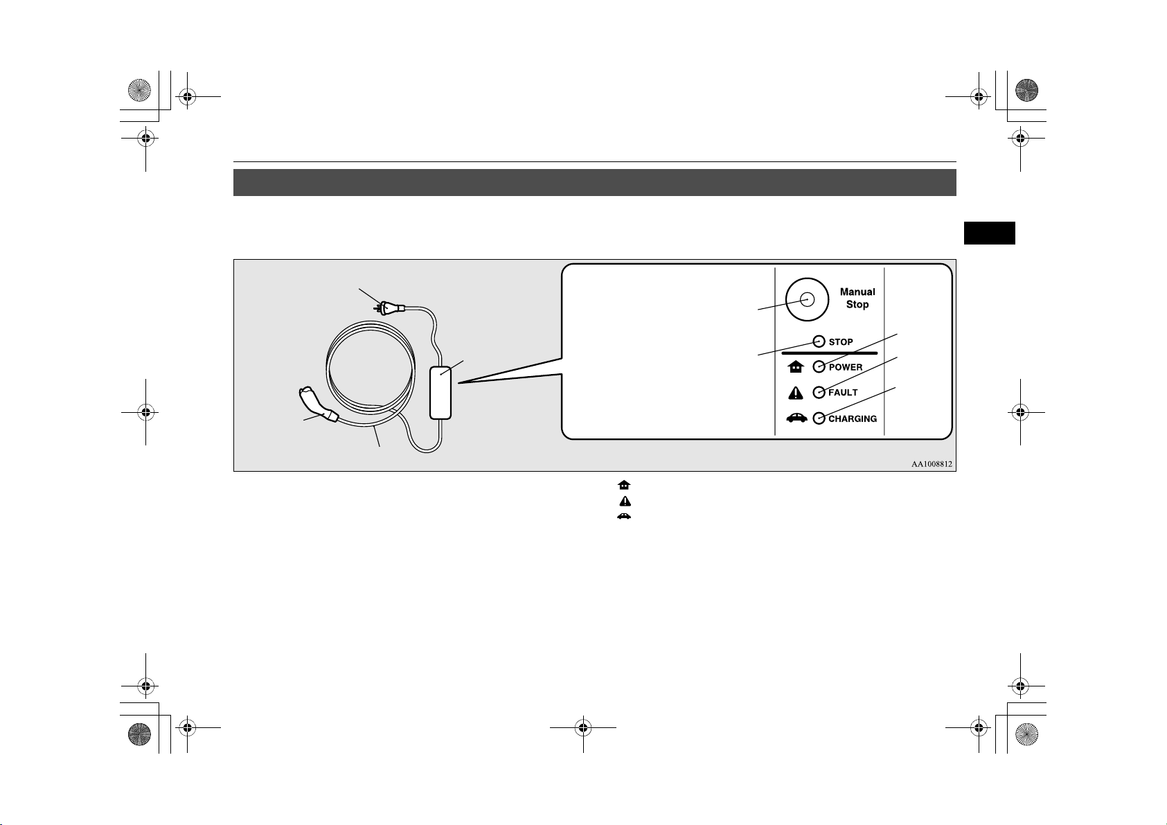
EV charging cable
EV charging cable
Yo u r v e hi c l e i s eq u i p pe d wi t h an E V c h a rg i ng c a bl e t ha t co n s is t s of a ca b l e ( A ), c on t r o l b o x ( B ), E V c h a rg i n g c a b le p l ug ( C) , a nd normal charge
connector (D).
E08301101092
3
E- Manual stop button
F- Stop indicator
G ( )-
H ( )-
POWER indicator
FAULT ind ic ator
I ( )- CHARGING indicator
To s to p char gi ng, si mp ly p re ss m anua l st op but to n (E) a nd s top in di cato r (F ) is i ll um inat ed . Re-c on ne ct th e EV char ging c ab le plug (C) to charge
again.
POWER (G), FAULT (H) and CHARGING (I) indicators located on the control box will illuminate/blink in response to the following conditions:
Charging 3-5
Page 31

BK0203201EN.book 6 ページ 2013年11月19日 火曜日 午前11時50分
EV charging cable
: Illuminates : Blinking : Not illuminates
POWER
3
POWER
FAULT
FAULT
CHARGING
CHARGING
Operating condition
Every time the charging cable plug (C) is connected to an outlet, all indicator lamps illuminate
for 0.5 seconds.
After initial processing is completed, when the normal charge connector is not connected to the
charge port, or the normal charge connector is connected to the charge port but charging is not
being performed.
While the drive battery is being charged.
When charging is completed.
Abnormal operating condition and corrective action
When an electric leakage occurs or the EV charging cable malfunctions
Stop using the EV charging cable immediately and contact a MITSUBISHI MOTORS Authorised Service Point.
When the EV charging cable malfunctions
Stop using the EV charging cable immediately and contact a MITSUBISHI MOTORS Authorised Service Point.
If the control box indicator lamp does not illuminate after connecting the charging cable plug to
the outlet, check the circuit breaker for the outlet. If the breaker has tripped, the circuit may not
be suitable for use with EV charging cable. You should have a licensed electrician inspect and
repair the electrical circuit. If the breaker is not tripped, Stop using the EV charging cable and
contact a MITSUBISHI MOTORS Authorised Service Point.
3-6 Charging
Page 32

WARNING
CAUTION
NOTE
WARNING
CAUTION
NOTE
Hook
Rope
BK0203201EN.book 7 ページ 2013年11月19日 火曜日 午前11時50分
If the POWER or CHARGING indicator
does not illuminates or the FAULT indicator blinks or illuminates during normal
charging, please contact a MITSUBISHI
MOTORS Authorised Service Point.
Do not charge when the EV charging
cable is coiled up.
The cable may be heated and resulting in
fire.
Do not alter or disassemble the EV charg-
ing cable. Doing so could cause a fire, electric shock or injury.
Be sure to install the cap to the normal
charge connector and store the EV charging cable in a place where the cable is not
exposed to water or dust. Entry of foreign
matter such as water or dust in the metal
terminal of the normal charge connector
or charging cable plug may cause a fire or
malfunction. Contact with a metal such as
wire or tool may cause a fire, electric
shock or malfunction.
Never force the connection if the EV
charging cable or connector shows damage or is not easily connected due to foreign material entering the connector or
the outlet. And never use an outlet that is
worn, damaged, or will not hold the plug
firmly. Doing so could cause fire, an electric shock, or short circuit.
Pay attention to the following for handling
the EV charging cable.
Damage to the cable could cause a fire,
electric shock, or short circuit.
•Do not drop the cable or do not give
strong impact to it.
•Do not pull with undue force.
•Do not twist.
•Do not drag.
•Do not put an object on top.
•Do not put the cable close to a heating
unit including heater.
Do not connect the normal charge cable to an
outlet that has a lower rating than the current
value described on the control box.
All indicators are illuminated momentarily
for confirming operation when the charging
cable plug is inserted into an outlet. After
that the POWER indicator and the CHARGING indicator is continuously illuminated.
The CHARGING indicator will start to blink
when the charging is completed. The
POWER indicator is continuously illuminated while the charging cable plug is
inserted into an outlet.
EV charging cable
Handling and storing the control box
E08301201064
3
While charging, prevent damage to the con-
trol box by attaching a rope as shown in the
following illustration.
Use a hook with a load capacity over 4 kg.
Check the rope has no damage and is not
loose before use.
Cleaning the EV charging cable
E08301301065
1. Lightly wipe these off with a soft cloth
soaked in a mild soap and water solution.
Charging 3-7
Page 33

WARNING
CAUTION
WARNING
WARNING
BK0203201EN.book 8 ページ 2013年11月19日 火曜日 午前11時50分
Normal charging (charging method with rated AC 240 V outlet)
2. Wipe off all the detergent with a soft cloth
dipped in fresh water and thoroughly
wrung out.
3. Wipe all moisture off and dry in a shaded,
3
well-ventilated area.
When cleaning, be sure to remove the
charging cable plug and the normal
charge connector from the outlet. Do not
connect or disconnect the plug and the
connector with wet hand. Doing so could
cause an electric shock.
Do not expose the metal terminal of the
normal charge connector or the charging
cable plug to water or neutral detergent.
Using in wet with water could cause a fire
or an electric shock.
Never use benzine, petrol, or other organic
solvents, or acid or alkaline solvents. Doing
so could cause deformation, discolour, or
malfunction. Also, these substances may be
present in various cleaners, so check carefully before using.
Normal charging (charging
method with rated AC 240 V
outlet)
For safety, do not allow children or people
who are not familiar with charging to
charge for themselves. Also, do not use the
normal charge connector within reach of
children.
Persons who use electro-medical appara-
tus such as implantable cardiac pacemaker or implantable cardioverterdefibrillator must check effect from
charging with the manufacturer of electro-medical apparatus. Electro-medical
apparatus operations could be affected by
charging.
If you use any medical electric devices, be
careful the following precautions.
•Keep away from the charge connector or
control box.
•Do not stay inside of the vehicle.
•Do not get on inside of the vehicle, for
example to remove or place an item in
the passenger compartment.
•Do not open the rear hatch, for example
to remove or place an item in the cargo
area.
Charging may affect the operation of electric medical devices and result in serious
personal injury or death.
E08300901080
Do not charge when the EV charging
cable is coiled up.
Doing so the cable may be heated and
resulting in a fire.
Before charging, make sure that there is
no foreign matter such as dust at the normal charge port and the normal charge
connector.
At this time, do not touch the normal
charge port.
When foreign substances, such as dust,
have entered, please contact a MITSUBISHI MOTORS Authorised Service Point.
When the normal charge connector is con-
nected to the charge port, prevent foreign
matter such as water or dust from entering in the connection.
Connection with foreign matter such as
water or dust may cause a fire or an electric shock. Do not perform charging if
there is possibility of strong exposure to
water at the connection.
When you deal with charge apparatus, be
careful of the following points. It could
cause a fire, an electric shock and a short
circuit.
•Never pull the cable to remove the plug.
•Never submerge the EV charging connector, control box, or plug in water.
Please observe the following in order to
prevent accidents during charging such as
electrocution.
3-8 Charging
Page 34

WARNING
CAUTION
WARNING
NOTE
BK0203201EN.book 9 ページ 2013年11月19日 火曜日 午前11時50分
Normal charging (charging method with rated AC 240 V outlet)
•Only use the EV charging cable that is
supplied with the vehicle.
•Do not charge another vehicle by the EV
charging cable. The cable may over heat
and result in a fire.
•When charging outdoors, make sure to
use an outlet that is protected from water
entering.
•Do not perform charging with the car
cover.
•Do not connect or disconnect the plug
and connector with wet hands.
•Do not charge the battery if there is a
risk of lightning.
When the EV charging cable or the plug
are damaged or it cannot connect by
entering a foreign substance, do not connect the EV charging cable by force.
While it is normal for the connector and
charging cable to become warm during
charging, discontinue use immediately if
the connector or charging cable becomes
hot to the touch.
While it is normal for the control box to
become warm during charging, discontinue use immediately if the control box
becomes hot to the touch.
If abnormal smells are detected or the
vehicle produces smoke, quickly stop
charging.
Do not perform charging in a poorly ven-
tilated area or in an enclosed area. Keep
sparks, cigarettes, and flames away from
the auxiliary battery.
Flammable gas generated from the auxiliary battery during charging may be
trapped, resulting in explosion.
If charging is inevitably required, ventilate the area well.
Grasp the normal charge connector when
connecting or disconnecting the EV charging cable.
Grasping the cable may damage the cable
and could cause an electric shock, short
circuit, and/or fire.
During charging, the cooling fans inside the
engine room may automatically be operated
even if the operation mode of the power
switch in OFF.
Keep your hands away from the cooling fan
during charging.
Do not perform charging from other power
source like a generator. Doing so could cause
a malfunction.
If the charge connector is not easily con-
nected to the charge port due to foreign matter entering, never force the connection.
Doing so could damage the charging equipment or the vehicle. Please contact a MITSUBISHI MOTORS Authorised Service
Point.
The on board charger is only for rated AC
240 V outlets.
When connecting or disconnecting the nor-
mal charge connector, insert/pull out the connector straight.
Also, do not incline or twist the connector.
Doing so could cause a bad connection or
malfunction.
Make sure to lock the doors to prevent theft,
etc. during charging.
Charging port courtesy lamp
E08304101035
The charging port courtesy lamp (A) illuminates when the charging lid is opened.
3
Charging 3-9
Page 35

NOTE
A
B
WARNING
NOTE
B
C
D
BK0203201EN.book 10 ページ 2013年11月19日 火曜日 午前11時50分
Normal charging (charging method with rated AC 240 V outlet)
Charging from rated AC 240 V
outlet
3
Press the charging port courtesy lamp switch
(B) to turn on the charging port courtesy lamp
again.
The charging port courtesy lamp illuminat-
ing time can be adjusted.
For details, please consult a MITSUBISHI
MOTORS Authorised Service Point.
When the select position is not in “P”
(PARK) position, the charging port courtesy
lamp does not illuminate when the charging
lid is opened.
If the MITSUBISHI Remote Control is oper-
ated when the charging port courtesy lamp is
off, the lamp may illuminate.
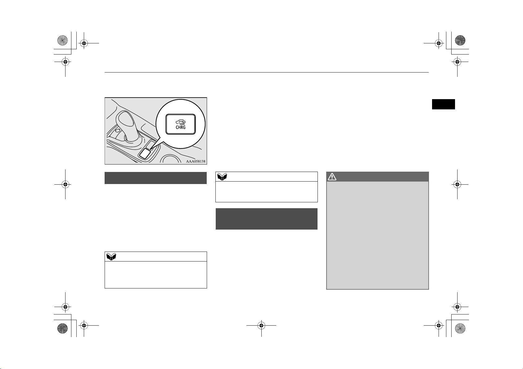
1. Firmly apply the parking brake, press the
electrical parking switch, then shift the
select position in “P” (PARK) position.
2. Turn off electrical equipment such as
lamps and put the operation mode of the
power switch in OFF.
3. Push the rear portion of the charging lid
(A) until it clicks, and open the charging
lid.
4. Press the tab (B) to open the inner lid (C).
E08301001091
It could cause electric leak, a fire or elec-
tric shock by entering water or dust into
the normal charge port.
Do not touch the metal terminal of the
normal charge port (D) and the normal
charge connector.
Doing so could cause an electric shock
and/or malfunction.
There is a hole on the charge port for water
drainage. If this hole is blocked and water
gets trapped in the charge port, do not
charge. Please contact a MITSUBISHI
MOTORS Authorised Service Point.
If the charge port is frozen, melt the ice using
a hair drier. Forcing the charge connector to
connect while frozen could result in malfunction.
3-10 Charging
Page 36

WARNING
AC 240 V 15 Amp plug
CAUTION
WARNING
NOTE
F
E
BK0203201EN.book 11 ページ 2013年11月19日 火曜日 午前11時50分
5. Insert the charging cable plug into an outlet.
Make sure that the plug is inserted all the
way into the outlet before use. If charging
is continued in the state where it is not
fully inserted the plug, there is a possibility of generating abnormal heat and
resulting in a fire.
To pr ev en t an el ec tr ic sh oc k o r fi re du e to
electric current leak, perform charging
using a waterproofed outlet with earthing
which is connected to an earth leakage circuit breaker.
Always use an earthed outlet protected by
a residual current detector, rated for
amperage equal to or greater than the
value specified by MITSUBISHI
MOTORS, and that is connected to a dedicated branch circuit. If the circuit is
shared, and another electrical device is
being used at the same time the vehicle is
charging, the circuit may heat abnormally,
the breaker may trip and the circuit may
cause adverse interference on the household electrical appliances such as televisions and audio systems.
Use the rated AC 240 V rated outlet indi-
vidually. If a multi plug adapter is connected and used with the EV charging
cable together with other devices, the outlet may overheat, resulting in a fire.
Use an outlet for EV charging which
waterproofing processing is carried out if
the installed position is outdoors or may
get wet by rain etc.
Use the outlet that is installed approx. 1
meter above the ground. If the outlet position
is too low, the control box may touch the
ground, which may lead to troubles such as
submersion in water or getting trampled on.
Normal charging (charging method with rated AC 240 V outlet)
Check it corresponds an outlet to your vehi-
cle which is installed in the following places.
•In your house etc.
•In a parking lot or garage
6. Remove the cap (E) on the normal charge
connector (F) and make sure that there is
no foreign matter such as dust at the end
of the normal charge connector and the
normal charge port.
3
Charging 3-11
Page 37

CAUTION
G
NOTE
BK0203201EN.book 12 ページ 2013年11月19日 火曜日 午前11時50分
Normal charging (charging method with rated AC 240 V outlet)
7. Connect the normal charge connector
until a click sound is heard without pressing the button (G).
3
Do not clasp the top of normal charge con-
nector. It could cause injury to touch the protrusion on the lid.
When put the operation mode of the power
switch in “ON” with the normal charge connector connected to the normal charge port,
the plug-in hybrid EV system cannot be
started.
Do not perform connect or disconnect the
normal charge connector repeatedly for a
short time. Charging may not be started.
Even if the power switch is ON with the nor-
mal charge connector is inserted in the normal charge port, it will not be in the state
which can be driven. During charging, if you
want to put the operation mode in OFF, when
the operation mode of the power switch is
ON, make sure the select position is in “P”,
take your foot off the brake pedal and press
the power switch. If the brake pedal is
depressed, the operation mode cannot be put
in OFF.
3-12 Charging
Page 38

I
H
J
NOTE
K
CAUTION
NOTE
NOTE
BK0203201EN.book 13 ページ 2013年11月19日 火曜日 午前11時50分
8. Make sure that the charging indicator (H)
on the instrument cluster is illuminated.
When the normal charge connector is con-
nected to the charge port, the charging indicator will blink. When charging is started,
the charging indicator is illuminated.
If one of the doors is opened or the multi-
information display switch is operated, the
drive battery level display (I) appears in the
multi-information display and indicates the
drive battery level. In addition, when the
remaining time is less than 1 hour, the predicted charging time display (J) appears --:-and does not indicate a malfunction.
9. Charging is complete when the charging
indicator turns off. Pull out the normal
charge connector while pressing the button (K).
Normal charging (charging method with rated AC 240 V outlet)
Be sure to check the normal charge connec-
tor is removed from the normal charge port.
Since it will change into the state which can
be started the vehicle when the power switch
is operated if the normal charge connector
does not locked completely, resulting in an
unexpected accident.
Charging can be stopped half way. In this
case, also, pull out the normal charge connector while pressing the button. Pressing
the manual stop button on the control box
can also stop charging.
Refer to “EV charging cable” on page 3-5.
10. Close the inner lid and press the rear of
the normal charging lid until it clicks to
close it.
3
Make sure that the inner lid is completely
If the charging indicator is not illuminated, charging has not started.
Make sure that the normal charge port and
the plug are correctly connected, and per-
closed.
If the normal charging lid is forcibly closed
without completely closing inner lid, the
hinge on the inner lid may be broken.
form charging from Step 5 again.
11. Remove the charging cable plug from the
outlet.
Charging 3-13
Page 39

WARNING
BK0203201EN.book 14 ページ 2013年11月19日 火曜日 午前11時50分
Normal charging (charging method with rated AC 240 V outlet)
12. Install the cap on the normal charge connector.
After charging, be sure to close the inner
3
lid and the normal charging lid completely.
Be careful that water or dust does not
enter in the normal charge port, inner lid
and normal charge connector.
Entry of water or dust could cause electric
current leakage, resulting in a fire or electric shock.
After charging, be sure to disconnect the
charge connector from the charge port.
If the charge connector is only partially
engaged and the connector latch is
unlocked, you could put the operation
mode of the power switch in “ON” and the
vehicle could start moving. It could lead to
an unexpected accident.
After charging, be sure to disconnect the
plug from the outlet.
If the plug is left connected to the outlet,
immersion in water or tampering may
cause leakage or an electric shock.
3-14 Charging
Page 40

BK0203201EN.book 15 ページ 2013年11月19日 火曜日 午前11時50分
Charging troubleshooting guide
Symptom Possible cause Possible solution
Charging cannot be
started.
The operation mode of the
power switch in ON
The drive battery is already
fully charged.
The temperature of the drive
battery is too high or too low
to charge.
The auxiliary battery is discharged.
The vehicle or the charging
cable has a malfunction.
Put the operation mode of the power switch in “OFF” before charging.
Charging cannot be performed if the drive battery is already fully charged. Charging
automatically turns off if the drive battery is fully charged.
Confirm the drive battery temperature.Refer to “Cautions and actions to deal with
intense heat” on page 2-8 and “Cautions and actions to deal with intense cold” on page
2-9.
The drive battery can not be charged if the vehicle electrical systems cannot be turned
on. If the auxiliary battery is discharged, charge or emergency start the auxiliary battery.
Refer to “Emergency starting” on page 9-2.
The vehicle or charging cable may have a malfunction. Confirm if the warning lamp on
the meter is illuminated. Confirm if the indicator on the control box is indicating a malfunction. If a warning is displayed, stop charging and contact a MITSUBISHI MOTORS
Authorised Service Point.
Charging troubleshooting guide
E08301501054
3
Charging 3-15
Page 41

BK0203201EN.book 16 ページ 2013年11月19日 火曜日 午前11時50分
Charging troubleshooting guide
Symptom Possible cause Possible solution
Normal charging cannot be started.
3
There is no electrical power
coming from the outlet.
The charge connector is not
connected correctly.
The charge connector was
connected and disconnected
repeatedly in a short time.
A charging cable for other
vehicle is used.
A normal charger which does
not correspond to your vehicles is used.
Reservation of charging timer
is set up by MITSUBISHI
Remote Control. (Vehicle
with MITSUBISHI Remote
Control)
Confirm that there has not been a power failure. Make sure the breaker is on. If an outlet
with a timer device installed is used, power will only be available at the time set by the
timer.
Confirm if the POWER indicator on the control box is illuminated.
Confirm the charge connector is connected correctly.
Disconnect the charge connector, wait for a while, then start charging procedure again
from the beginning.
Use the EV charging cable only for your vehicle.
Consult an administrator or a maker of the normal charger that it corresponds to your
vehicle. Also perform normal charging according to the operating procedure indicated
on the body of normal charger.
The normal charging can not be started when the charging cable is connected, if the
charging timer is set. Cancel all the charging timer settings, if you want to start the normal charging immediately.
3-16 Charging
Page 42

BK0203201EN.book 17 ページ 2013年11月19日 火曜日 午前11時50分
Symptom Possible cause Possible solution
Normal charging is
discontinued.
There is no power coming
from the outlet.
The EV charging cable has
been disconnected.
The button on the normal
charge connector has been
pressed.
The temperature of the drive
battery is too high or too low
to charge.
Charging is stopped by the
normal charge timer.
The Charging timer was set
up by the MITSUBISHI
Remote Control after starting
of normal charging.
There may have been a electrical power failure, or the breaker may have failed.Charging
will resume when the power source is reset.
Check that the EV charging cable has not been disconnected.
If the charge connector button is pressed for a long period of time, charging will be
stopped. Start the charging procedure again.
Confirm the drive battery temperature.
Refer to “Cautions and actions to deal with intense heat” on page 2-8 and “Cautions and
actions to deal with intense cold” on page 2-9.
Charging will stop depending on the timer function setting of the normal charge device.
If you need to charge the drive battery more, start the charging procedure again.
Cancel all the charging timer settings. Charging is automatically restarted if you cancel
the charging timer.
MITSUBISHI Remote Control*
3
MITSUBISHI Remote Control
*
E08304200026
The MITSUBISHI Remote Control allows to
operate the vehicle within the communication
range of the wireless LAN device (which
conforms to IEEE 802.11b and supports iOS
or Android). The following operations are
available.
1- Wireless LAN device
2- Antenna
Charging timer
If you specify the charge start and/or stop
time with the normal charge cable connected, charging is started and/or stopped
at that time.
Remote climate control
By setting the remote climate control to
operate at a predetermined time, cabin
comfort can be improved or visibility can
be ensured (defrosting/demisting) before
getting on the vehicle.
Charging 3-17
Page 43

NOTE
WARNING
CAUTION
NOTE
BK0203201EN.book 18 ページ 2013年11月19日 火曜日 午前11時50分
MITSUBISHI Remote Control*
Customize (function setting change)
The function setting of the keyless operation system, security alarm, outside rearview mirror, operation mode of the power
3
switch, air conditioning, lamps and windscreen wipers can be changed by MITSUBISHI Remote Control.
The electric heater is required to activate the
reservation functions of heater, defroster and
demister.
Due to the communication distance differs
depending on the wireless LAN device, the
communication may down.
Devices that support wireless LAN are
required to communicate with the vehicle
using the MITSUBISHI Remote Control.
Also, an SSID* (A) and password (B) are
required to connect a wireless LAN device to
the vehicle. The SSID and password come
with the key at the time of your purchase of
the vehicle.
*: An SSID is the identifier of an access
point for IEEE 802.11 series wireless
LAN. It is displayed on wireless LAN
devices.
For the operation method of the MITSUBISHI Remote Control, please visit Mitsubishi
Motors’ Web site:
http://www.mitsubishi-motors.com/en/products/outlander_phev/app/remote/index.html
If you need further information, please
contact a MITSUBISHI MOTORS
Authorized Service Point.
Do not use the MITSUBISHI Remote
Control if children, persons in need of
care, pets, etc. are in the vehicle. Even if
the remote climate control is used, the
cabin may become hot or cold due to some
reasons such as automatic stop of the system. The cabin temperature may quickly
rise in sunshine, which poses a risk of heat
stroke and dehydration. In cold weather,
on the other hand, the cabin temperature
may quickly drop. Either of which could
lead to death in the worst case.
The cooling fan in the engine compart-
ment may operate automatically when
charging or when operating air conditioner. Do not bring your hand close to the
cooling fan during charging.
Do not use the timer charging or the remote
climate control with a car cover.
Keep the following points in mind when
using a wireless LAN device:
•Communication speed and range vary
depending on the wireless LAN devices and
the surrounding conditions (radio environment, obstacles, parking area environment,
etc.).
3-18 Charging
Page 44

NOTE
NOTE
NOTE
BK0203201EN.book 19 ページ 2013年11月19日 火曜日 午前11時50分
MITSUBISHI Remote Control*
•Due to the characteristics of radio waves,
communication speed tends to decrease as
the communication distance increases. Use
your wireless LAN device at a short distance from the vehicle for better response.
•When a microwave oven or ISM (industrial, scientific and medical) equipment is
being used, the communication speed and
range of wireless LAN devices may
decrease. Use your wireless LAN device
away from these appliances and equipment.
•If a wireless LAN device and Bluetooth
(registered trademark of Bluetooth SIG,
Inc.) are used simultaneously, the communication speed and range of each device
may decrease. Use your wireless LAN
device away from Bluetooth devices.
Wireless LAN devices may not communicate
with the vehicle, or may not operate normally or stably in the following environment
or situations. Check that the device can communicate with your vehicle before use.
•There is an obstruction such as a concrete
or metal wall between the vehicle and wireless LAN device.
•The vehicle is surrounded by tall vehicles
in a parking lot.
•There are facilities nearby that emit strong
radio waves, such as a TV tower, transformer substation, broadcasting station or
airport.
•There is a communication device such as a
mobile phone or radio, or an electric device
such as a personal computer near the wireless LAN device.
•The wireless LAN device is in contact with
or covered by a metal object.
•The battery of the wireless LAN device has
run down.
The MITSUBISHI Remote Control cannot
be used under the following conditions:
•The wireless LAN device is turned off.
•The MITSUBISHI Remote Control application software is not installed.
•The MITSUBISHI Remote Control application software is not running.
•The wireless LAN device is not registered
on the vehicle or it is not connected to the
vehicle.
•The wireless LAN device is out of the communication range.
•The wireless LAN device is connected to
other wireless LAN device.
•The wireless LAN device has failed, or its
battery has run out.
Some charging facilities have a timer func-
tion that turns the power on or off at a specific time of the day. When charging at a
facility with a timer function, make sure that
the charging timer is set within the time
period when the power in the charging facility is on.
The auxiliary battery is automatically and
periodically charged using electrical power
stored in the drive battery.
While the remote climate control is operating
or the charging, the cooling fan or air conditioner compressor may start operating and its
sound may be heard. This is normal.
The remote climate control operates in its
own mode based on the mode selected on the
wireless LAN device, regardless of the
switch setting of the vehicle’s air conditioner.
Air conditioning performance may deterio-
rate or the remaining quantity of the drive
battery may decrease under the following
conditions:
•In extremely hot weather.
•In hot sunshine.
•In extremely cold weather.
If the remote climate control is started during
charging, the time until full charge may
extend or the charging rate may decrease.
When the remaining quantity of the drive
battery is decreased, the remote climate control does not operate or it may stop on the
way.
3
Charging 3-19
Page 45

NOTE
BK0203201EN.book 20 ページ 2013年11月19日 火曜日 午前11時50分
MITSUBISHI Remote Control*
When the auxiliary battery is removed, the
timer control of the MITSUBISHI Remote
3
Control is reset and each function of the
MITSUBISHI Remote Control can not be
used. Also the drive battery can not be
warmed up.
Communicate the wireless LAN device and
your vehicle again.
3-20 Charging
Page 46

BK0203201EN.book 1 ページ 2013年11月19日 火曜日 午前11時50分
Locking and unlocking
Keys ..................................................................................................4-2
Key number tag ................................................................................4-2
Electronic immobilizer (Anti-theft starting system).........................4-3
Keyless entry system ........................................................................ 4-3
Keyless operation system .................................................................4-6
Doors...............................................................................................4-14
Central door locks...........................................................................4-15
“Child-protection” rear doors .........................................................4-15
Tai lg at e * . .. .. .... .. .. .... .. .. ..... .. .... .. .. ..... .. .... .. .. ..... .. ..... .. .... .. .. ..... .. .... .. .. 4- 16
Electric tailgate* .............................................................................4-17
Inside tailgate release......................................................................4-24
Security alarm system *..................................................................4-24
Electric window control..................................................................4-29
Sunroof * ........................................................................................4-31
4
Page 47

WARNING
NOTE
NOTE
BK0203201EN.book 2 ページ 2013年11月19日 火曜日 午前11時50分
Keys
Keys
E00300103572
The key fits all locks.
4
1- Keyless operation key
2- Keyless operation key (with electric
tailgate switch)
3- Emergency key
When carrying a key on flights, do not
press any switches on the key while on the
plane. If a switch is pressed on the plane,
the key emits electromagnetic waves,
which could adversely affect the plane’s
flight operation.
When carrying a key in a bag, be careful
that no switches on the key can be easily
pressed by mistake.
The key is a precision electronic part with a
built-in signal transmitter. Please observe the
following in order to prevent a malfunction.
•Do not leave anywhere that is exposed to
direct sunlight, for example on the dashboard.
•Do not disassemble or modify.
•Do not excessively bend the key or subject
it to a strong impact.
•Do not expose to water.
•Keep away from magnetic key rings.
•Keep away from audio systems, personal
computers, TVs, and any other equipment
that generates a magnetic field.
•Keep away from devices that emit strong
electromagnetic waves, such as cellular
phones, wireless devices and high frequency equipment (including medical
devices).
• Do not wash with ultrasonic cleaners or
similar equipment.
•Do not leave the key where it may be
exposed to high temperature or high humidity.
The plug-in hybrid EV system is designed so
that it will not start if the ID code registered
in the immobiliser computer and the key’s ID
code do not match. Refer to the section entitled “Electronic immobiliser” for details and
key usage.
[For vehicles equipped with the security
alarm system]
Pay attention to the following if the security
alarm is set to “Active”.
Refer to “Security alarm system” on page
4-24.
•If the security alarm is in the system armed
mode, the alarm will sound if the doors are
opened after being unlocked with the key,
the inside lock knob or the central door lock
switch.
•Even if the security alarm is set to
“Active”, the system preparation mode is
not entered if the keyless entry system or
the keyless operation function was not used
to lock the vehicle.
Key number tag
E00312700011
The key number is stamped on the tag as indicated in the illustration.
Make a record of the key number and store
the key and key number tag in separate
places, so that you can order a key from your
authorised MITSUBISHI MOTORS dealer in
the event the original keys are lost.
4-2 Locking and unlocking
Page 48

NOTE
CAUTION
NOTE
BK0203201EN.book 3 ページ 2013年11月19日 火曜日 午前11時50分
If you lose one of keyless operation keys,
contact your MITSUBISHI MOTORS
Authorised Service Point as soon as possible.
To obt ain a rep lac em ent or extra sp are ke y,
take your vehicle and all remaining keys to
your MITSUBISHI MOTORS Authorised
Service Point. All the keys have to be re-registered in the immobiliser computer unit. The
immobilizer can register as follows.
•Keyless operation key: up to 4 different
keys
Electronic immobilizer
(Anti-theft starting system)
E00300202996
The electronic immobilizer is designed to
reduce significantly the possibility of vehicle
theft. The purpose of the system is to immobilize the vehicle if an invalid start is
attempted. A valid start attempt can only be
achieved by using a key “registered” to the
immobilizer system.
If the plug-in hybrid EV system does not
start, we recommend you to contact your
MITSUBISHI MOTORS Authorised Service
Point.
Do not modify or add parts to the immobi-
lizer system. Doing so could cause the
immobilizer to malfunction.
Keyless entry system
Press the remote control switch, and all doors
and the tailgate will be locked or unlocked as
desired. It is also possible to operate the outside rear-view mirrors.
Electronic immobilizer (Anti-theft starting system)
1- LOCK switch
2- UNLOCK switch
3- Electric tailgate switch*
4- Indicator lamp
To l oc k
Press the LOCK switch (1). All the doors and
the tailgate will be locked. The turn-signal
E00300303721
lamps will blink once when the doors and the
tailgate are locked.
To un lo ck
Press the UNLOCK switch (2). All the doors
and the tailgate will be unlocked. If the doors
and tailgate are unlocked when the front room
lamp switch is in the “DOOR” position or the
rear room lamp switch is in the middle ()
position, the room lamp will illuminate for
4
Locking and unlocking 4-3
Page 49

NOTE
NOTE
NOTE
BK0203201EN.book 4 ページ 2013年11月19日 火曜日 午前11時50分
Keyless entry system
approximately 15 seconds and the turn-signal
lamps will blink twice.
The position and tail lamps can also be set to
turn on for about 30 seconds. Refer to
“Instruments and controls: Welcome light” on
page 6-43.
4
The door and tailgate unlock function can be
set so that only the driver’s door unlocks
when the UNLOCK switch (2) is pressed
once.
If the door and tailgate unlock function is set
to work as described above, all the doors and
the tailgate unlock when the UNLOCK
switch is pressed two times in succession.
Refer to “Setting of door and tailgate unlock
function” on page 4-5.
If the UNLOCK switch (2) is pressed and
any of the doors or tailgate is not opened
within approximately 30 seconds, relocking
will automatically occur.
It is possible to modify functions as follows:
For further information, please contact your
MITSUBISHI MOTORS Authorised Service
Point.
On vehicles equipped with Mitsubishi MultiCommunication System (MMCS), screen
operations can be used to make the adjustment. Refer to the separate owner’s manual
for details.
•The time for automatic relocking can be
changed.
•The confirmation function (blinking of the
turn-signal lamps) can be set to operate
only when the doors and tailgate are locked
or only when the doors and tailgate are
unlocked.
•The confirmation function (this indicates
locking or unlocking of the doors and tailgate with the blink of the turn-signal lamps)
can be deactivated.
•The number of times the turn-signal lamps
are blinked by the confirmation function
can be changed.
Operation of the outside rearview mirrors (Vehicles
equipped with the mirror
retractor switch)
To fold
Within 30 seconds of locking the doors and
tailgate using the LOCK switch (1), press the
LOCK switch twice rapidly to fold the outside rear-view mirrors.
E00310801259
To e xt en d
Within 30 seconds of unlocking the doors and
tailgate using the UNLOCK switch (2), press
the UNLOCK switch twice rapidly to return
the outside rear-view mirrors to their
extended positions.
The outside rear-view mirrors are not initially
set to work as described above. If you want
them to work as described above, you need to
set them so that they do not retract/extend
when the doors and tailgate are
locked/unlocked using the keyless entry system or keyless operation function.
Refer to “Starting and driving: Outside rearview mirrors” on page 7-7.
For details, please consult a MITSUBISHI
MOTORS Authorised Service Point.
In a vehicle equipped with the Mitsubishi
Multi-Communication System (MMCS), it is
possible to change the setting by means of
screen operations.
Refer to the separate owner’s manual for
details.
The outside rear-view mirrors automatically
retract when all the doors and tailgate are
locked using the keyless operation function.
Refer to “Starting and driving: Outside rearview mirrors” on page 7-7.
4-4 Locking and unlocking
Page 50

NOTE
NOTE
NOTE
BK0203201EN.book 5 ページ 2013年11月19日 火曜日 午前11時50分
The keyless entry system does not operate
when the door or tailgate is open.
The remote control switch will operate
within about 4 m from the vehicle. However,
the operating range of the remote control
switch may change if the vehicle is located
near a power station, or radio/TV broadcasting station.
If either of the following problems occurs,
the battery may be exhausted.
•The remote control switch is operated at the
correct distance from the vehicle, but the
doors and tailgate are not locked/unlocked
in response.
•The indicator lamp (4) is dim or does not
come on.
•Keyless operation key: up to 4 remote control switches
Setting of door and tailgate
unlock function
The door and tailgate unlock function can be
set to the following two conditions.
Each time the door and tailgate unlock function is set, a chime will sound to tell you the
condition of the door and tailgate unlock
function.
Number
of chimes
For further information, please consult your
MITSUBISHI MOTORS Authorised Service Point.
If you replace the battery yourself, refer to
“Procedure for replacing the remote control
switch battery” on page 4-5.
If your remote control switch is lost or dam-
aged, please contact your MITSUBISHI
MOTORS Authorised Service Point for a
replacement remote control switch.
If you wish to add a remote control switch,
we recommend you to contact your
MITSUBISHI MOTORS Authorised Service
Point.
The below remote control switches are available for your vehicle.
One chime
Two
chimes
1. Put the operation mode in OFF.
2. Place the combination headlamps and dipper switch in the “OFF” position, and
leave the driver’s door open.
3. Press the LOCK switch (1) for 4 to 10
seconds and press the UNLOCK switch
(2) during this time.
All doors and the tailgate
unlock
Driver’s door unlock only
Condition
E00310301296
Keyless entry system
4. Release in sequence the LOCK and
UNLOCK switches within 10 seconds of
pressing the LOCK switch in step 3.
On vehicles equipped with Mitsubishi Multi-
Communication System (MMCS), screen
operations can be used to make the adjustment. Refer to the separate owner’s manual
for details.
Procedure for replacing the
remote control switch battery
E00309501243
Before replacing the battery, remove static
electricity from your body by touching a
metal grounded object.
4
Locking and unlocking 4-5
Page 51

NOTE
NOTE
CAUTION
+ side
- side
Coin type
battery
CR2032
WARNING
BK0203201EN.book 6 ページ 2013年11月19日 火曜日 午前11時50分
Keyless operation system
1. With the MITSUBISHI mark facing you,
insert the cloth-covered tip of a straight
blade (or minus) screwdriver into the
notch in the case and use it to open the
case.
3. Install a new battery with the + side (A)
up.
4
4. Close the case firmly.
5. Check the keyless operation function to
see that it works.
Be sure to perform the procedure with the
MITSUBISHI mark facing you. If the
MITSUBISHI mark is not facing you when
you open the case, the transmitter may come
out.
2. Remove the old battery.
Yo u m a y p u rc ha s e a r e pl ac e me n t b a tt er y a t
an electric appliance store.
A MITSUBISHI MOTORS Authorised Ser-
vice Point can replace the battery for you if
you prefer.
When the remote control switch case is
opened, be careful to keep water, dust, etc.
out. Also, do not touch the internal components.
Keyless operation system
E00305601608
The keyless operation system allows you to
lock and unlock the doors and tailgate and
start the engine simply by carrying the keyless operation key with you.
The keyless operation key can also be used as
the keyless entry system remote control
switch.
Refer to “Keyless entry system” on page 4-3.
The driver should always carry the keyless
operation key. This key is necessary for locking and unlocking the doors and tailgate,
starting the engine and otherwise operating
the vehicle, so before locking and leaving the
vehicle, be sure to check that you have the
keyless operation key.
People with implantable cardiac pacemak-
ers or implantable cardiovascular-defibrillators should not go near the exterior
transmitters (A) or the interior transmitters (B). The radio waves used by the keyless operation system could adversely
affect implantable cardiac pacemakers or
implantable cardiovascular-defibrillators.
4-6 Locking and unlocking
Page 52

WARNING
NOTE
NOTE
BK0203201EN.book 7 ページ 2013年11月19日 火曜日 午前11時50分
•You can limit operations to locking and
unlocking the doors and tailgate.
•You can limit operations to starting the
engine.
• The keyless operation system can be disabled.
When keyless operation system operations are modified, the transmitters operate as follows.
•Only locking and unlocking doors or
tailgate: exterior transmitter and interior
transmitter
•Only starting the engine: interior transmitter
When using electromedical devices other
than implantable cardiac pacemakers or
implantable cardiovascular-defibrillators, contact the electromedical device
manufacturer ahead of time to determine
the affects of radio waves on the devices.
Electromedical device operations could be
affected by radio waves.
Yo u ca n l imi t t h e po s si b le o pe r at i on s o f
the keyless operation system in the following ways. (The keyless operation system can be used as a keyless entry
system.) Please consult a MITSUBISHI
MOTORS Authorised Service Point.
The keyless operation key uses an ultra-weak
electromagnetic wave. In the following
cases, the keyless operation system may not
operate properly or may be unstable.
•When there is equipment nearby that emits
strong radio waves, such as: a power station, a radio/TV broadcasting station or an
airport.
•The keyless operation system is carried
together with a communications device
such as a cellular phone or radio set, or with
an electronic device such as a personal
computer.
•The keyless operation key is touching or
covered by a metal object.
Keyless operation system
•A keyless entry system is being used
nearby.
•When the keyless operation key battery is
worn out.
•When the keyless operation key is set down
in an area with strong radio waves or noise.
In such cases, use the emergency key.
Refer to “To operate without using the keyless operation function” on page 4-13.
Because the keyless operation key receives
signals in order to communicate with the
transmitters in the vehicle, the battery continually wears down regardless of keyless
operation key use. The battery life is 1 to 3
years, depending on usage conditions. When
the battery wears out, replace the battery
according to the description in this manual or
have it replaced at your MITSUBISHI
MOTORS Authorised Service Point.
Refer to “Procedure for replacing the remote
control switch battery” on page 4-5.
Because the keyless operation key continu-
ally receives signals, strong radio wave
reception could affect battery wear. Do not
leave the key near a TV, personal computer,
or other electronic device.
Operating range of the keyless
operation system
E00305700556
If you are carrying the keyless operation key,
enter the operating range of the keyless oper-
4
Locking and unlocking 4-7
Page 53

NOTE
NOTE
NOTE
BK0203201EN.book 8 ページ 2013年11月19日 火曜日 午前11時50分
Keyless operation system
ation system, and press the driver’s or front
passenger’s door lock/unlock switch, the tailgate LOCK switch or the tailgate open
switch, the ID code for your key is verified.
Yo u c a n o nl y l oc k a n d u n lo ck t h e d oor s and
tailgate and start the engine if the ID codes of
4
your keyless operation key and the vehicle
match.
If the keyless operation key battery is wear-
ing out or there are strong electromagnetic
waves or noise present, the operating range
may become smaller and operation may
become unstable.
Operating range for locking and
unlocking the doors and tailgate
The operating range is about 70 cm from the
driver’s door handle, front passenger’s door
handle, and tailgate handle.
*:Forward direction
Operating range
:
Locking and unlocking are only possible
when the door or tailgate is operated while
the keyless operation key is being detected.
Operation may not be possible if you are too
close to the front door, door window, or tailgate.
E00306200516
Even if the keyless operation key is within
70 cm of the driver’s door handle, front passenger’s door handle, or tailgate handle, if
the key is near to the ground or high up, the
system may not operate.
If the keyless operation key is within the
operating range, even someone not carrying
the key can lock and unlock the doors and
tailgate by pressing the driver ’s or front passenger’s door lock/unlock switch, the tailgate lock switch or the tailgate open switch.
Operating range for starting the
engine
E00306300285
The operating range is the interior of the
vehicle.
4-8 Locking and unlocking
*:Forward direction
Operating range
:
Page 54

NOTE
NOTE
Driver’s or front passenger’s door
lock/unlock switches
Tai lgat e s wi tch es
NOTE
BK0203201EN.book 9 ページ 2013年11月19日 火曜日 午前11時50分
Keyless operation system
Even if it is within the operating range, if the
keyless operation key is in a small item
holder such as the glove box, on top of the
instrument panel, door pocket or in the luggage area, it may be impossible to start the
engine.
If you are too close to the door or door win-
dow, the engine may start even though the
keyless operation key is outside the vehicle.
To ope ra te us in g th e ke yl es s
operation function
E00305800922
Locking the doors and tailgate
When you are carrying the keyless operation
key, if you press the driver’s or front passenger’s door lock/unlock switch (A), or the tailgate LOCK switch (B) within the operating
range, the doors and the tailgate are locked.
The turn-signal lamps will blink once.
Also refer to “Locking and unlocking: Doors,
Central door locks, Tailgate” on pages 4-14,
4-15 and 4-16.
For vehicles equipped with the mirror retrac-
tor switch, the outside rear-view mirrors
automatically retract when all the doors and
tailgate are locked using the keyless operation function.
Refer to “Starting and driving: Outside rearview mirrors” on page 7-7.
The keyless operation function does not
operate under the following conditions:
•The keyless operation key is inside the
vehicle.
•A door or the tailgate is open or ajar.
The tailgate open switch (C) can be used to
check that the vehicle is locked properly.
Press the tailgate open switch within about 3
seconds of locking the vehicle. If you wait
longer than 3 seconds and press the tailgate
open switch, the doors and tailgate will be
unlocked.
The time allowed for checking that the vehi-
cle is locked can be adjusted. For further
information, please contact your authorised
MITSUBISHI MOTORS dealer.
On vehicles equipped with Mitsubishi MultiCommunication System (MMCS), screen
operations can be used to make the adjustment. Refer to the separate owner’s manual
for details.
Unlocking the doors and tailgate
When you are carrying the keyless operation
key, if you press the driver’s or front passenger’s door lock/unlock switch (A), or the tailgate open switch (B) within the operating
range, all the doors and the tailgate are
unlocked.
If the front room lamp switch is in the
“DOOR” position or the rear room lamp
switch is in the middle () position at this
4
Locking and unlocking 4-9
Page 55

Driver’s and front passenger’s door
lock/unlock switches
Tai lgat e o pen s wit ch
NOTE
NOTE
BK0203201EN.book 10 ページ 2013年11月19日 火曜日 午前11時50分
Keyless operation system
time, the room lamp will turn on for 15 seconds. The turn-signal lamps will blink twice.
If the driver’s or front passenger’s door
lock/unlock switch is pressed and any of the
doors or tailgate is not opened within approximately 30 seconds, relocking will automati-
4
cally occur.
Also refer to “Locking and unlocking: Doors,
Central door locks, Tailgate” on pages 4-14,
4-15 and 4-16.
For vehicles equipped with the mirror retrac-
tor switch, the outside rear-view mirrors
automatically extend when all the doors and
tailgate are unlocked using the keyless operation function.
Refer to “Starting and driving: Outside rearview mirrors” on page 7-7.
The keyless operation function can be set so
that only the driver’s door unlocks when the
driver’s door lock/unlock switch is pressed.
If the keyless operation function is set to
work as described above, all the doors and
the tailgate unlock when the driver’s door
lock/unlock switch is pressed two times in
succession.
Refer to “Setting of door and tailgate unlock
function” on page 4-5.
The keyless operation function does not
operate under the following conditions:
•A door or the tailgate is open or ajar.
In order to make it possible to check that the
doors and tailgate are locked, you cannot
unlock them by using the tailgate open
switch for 3 seconds after locking them.
The time allowed for checking that the vehi-
cle is locked can be adjusted. For further
information, please contact your authorised
MITSUBISHI MOTORS dealer.
On vehicles equipped with Mitsubishi MultiCommunication System (MMCS), screen
operations can be used to make the adjustment. Refer to the separate owner’s manual
for details.
The time between unlocking and automatic
locking can be adjusted. Please consult a
MITSUBISHI MOTORS Authorised Service
Point.
On vehicles equipped with Mitsubishi MultiCommunication System (MMCS), screen
operations can be used to make the adjustment. Refer to the separate owner’s manual
for details.
Operation confirmation when locking
and unlocking
Operation can be confirmed as shown below.
However, the room lamp will only illuminate
if the front room lamp switch is in the
“DOOR” position or the rear room lamp
switch is in the middle () position.
When locking:
When
unlocking:
The turn-signal lamps blink
once.
The room lamp illuminates for
about 15 seconds, the turn-signal
lamps blink twice.
4-10 Locking and unlocking
Page 56

NOTE
NOTE
BK0203201EN.book 11 ページ 2013年11月19日 火曜日 午前11時50分
Keyless operation system
Functions can be modified as stated below.
For further information, please contact your
MITSUBISHI MOTORS Authorised Service
Point.
On vehicles equipped with Mitsubishi MultiCommunication System (MMCS), screen
operations can be used to make the adjustment. Refer to the separate owner’s manual
for details.
•Set the confirmation function (blinking of
the turn-signal lamps) to operate only when
the vehicle is locked or only when the vehicle is unlocked.
•Disable the operation confirmation function
(blinking of the turn-signal lamps).
•Change the number of blinks for the operation confirmation function (blinks of the
turn-signal lamps).
Warning activa tion
E00305901715
In order to prevent vehicle theft or the accidental operation of the keyless operation system, the buzzer and the display on the information screen
in the multi-information display are used to alert the driver.
If a warning is activated, always check the vehicle and the keyless operation key. The warning is also displayed if there is a fault in the keyless
operation system.
Item Display Buzzer Note (Solution)
Detection of failure Inner buzzer sounds
once
Fall of battery voltage Inner buzzer sounds
once
There is a fault in the keyless operation system.
The battery starts to run out, the warning is activated. (The warning is
not activated if the battery is completely dead.)
4
Locking and unlocking 4-11
Page 57

BK0203201EN.book 12 ページ 2013年11月19日 火曜日 午前11時50分
Keyless operation system
Item Display Buzzer Note (Solution)
Key not detected Inner buzzer sounds
once
4
Keyless operation key
reminder
Keyless operation key
take-out monitoring
system
Inner buzzer sounds
about 1 minute
Outer buzzer sounds
about 3 seconds intermittently
Inner buzzer sounds
once
Outer buzzer sounds
intermittently
When the engine switch is turned to the ACC or ON from OFF or when
the engine is started, the warning is activated, if any of the following
conditions is occurred.
•
Carrying another keyless operation key with a different code, or the
keyless operation key could be outside the operating range.
•
The battery of the keyless operation key is dead.
•
Communication is blocked by electric wave environment.
If the operation mode is in OFF and the driver’s door is opened with
the keyless operation key in the key slot, a warning is issued and the
outer buzzer sounds for about 3 seconds and the inner buzzer sounds
for about 1 minute to remind you to remove the key. If the key
removed from key slot, the buzzer is stopped.
•
When the vehicle is parked with the operation mode in any mode
other than OFF, if you close the door after opening any of the doors
and taking the keyless operation key out of the vehicle, a warning is
issued until the key is detected in the vehicle.
•
If you take the keyless operation key out of the vehicle through a
window without opening a door, the keyless operation key take-out
monitoring system does not operate.
•
It is possible to change the setting to make the keyless operation key
take-out monitoring system operate if you take the keyless operation
key out from the vehicle through a window without opening a door.
For further information, please contact a MITSUBISHI MOTORS
Authorised Service Point.
•
Even if you have the keyless operation key within the engine start
operating range, if the keyless operation key and vehicle ID codes
cannot be matched, for example due to the ambient environment or
electromagnetic conditions, the warning may be activated.
4-12 Locking and unlocking
Page 58

BK0203201EN.book 13 ページ 2013年11月19日 火曜日 午前11時50分
Item Display Buzzer Note (Solution)
Key lock-in prevention system
Door ajar prevention
system
Operation mode OFF
reminder system
Inner buzzer sounds
once
Outer buzzer sounds
about 3 seconds intermittently
Inner buzzer sounds
once
Outer buzzer sounds
about 3 seconds intermittently
Inner buzzer sounds
once
Outer buzzer sounds
about 3 seconds intermittently
Keyless operation system
••When the operation mode is in OFF, if you close all the doors and
the tailgate with the keyless operation key left in the vehicle and you
try to lock the doors and tailgate by pressing the driver’s or front
passenger’s door lock/unlock switch, or the tailgate LOCK switch, a
warning is issued and you cannot lock the doors and tailgate.
Make sure you have the keyless operation key with you before locking the doors. Even if you leave the keyless operation key inside the
vehicle, it is possible that the doors will lock depending on the surrounding environment and wireless signal conditions.
When the operation mode in OFF, if you try to lock the doors and tailgate by pressing the driver’s or front passenger’s door lock/unlock
switch, or the tailgate LOCK switch with one of the doors or the tailgate not completely closed, a warning is issued and you cannot lock the
doors and tailgate.
When the operation mode is in any mode other than OFF, if you close
all the doors and the tailgate then try to lock the doors and tailgate by
pressing the driver’s or front passenger’s door lock/unlock switch, or
the tailgate LOCK switch, a warning is issued and you cannot lock the
doors and tailgate.
4
To o pe ra te wi th out using the
keyless operation function
E00306000019
Emergency key
E00307201464
The emergency key is built into the keyless
operation key. If the keyless operation function cannot be used, for example because the
keyless operation key battery has worn out or
the vehicle battery is flat, you can lock and
unlock the driver’s door and start the engine
with the emergency key.
To us e th e eme rg ency ke y (A ), u nl oc k th e
lock knob (B) and remove it from the keyless
operation key (C).
Refer to “Doors” on page 4-14, or “If the keyless operation key is not operating properly”
on page 7-13.
Locking and unlocking 4-13
Page 59

NOTE
CAUTION
NOTE
NOTE
NOTE
BK0203201EN.book 14 ページ 2013年11月19日 火曜日 午前11時50分
Doors
Only use the emergency key for emergen-
cies. If the keyless operation key battery
wears out, replace it as quickly as possible so
that you can use the keyless operation key.
After using the emergency key, always return
4
it into the keyless operation key.
Doors
Make sure the doors are closed: driving with
doors not completely closed is dangerous.
Never leave children in the vehicle unat-
tended.
Be careful not to lock the doors while the
key is inside the vehicle.
To pre ven t the key fr om bein g lo cke d insi de
the vehicle, neither the lock knob on the
driver’s door nor the key can be used to lock
the driver’s door when it is open.
E00300402291
To lock or unlock with the key
1- Lock
2- Unlock
When locking or unlocking with the key,
only the driver’s door will be locked or
unlocked.
To lo ck or unlock a ll do ors a nd th e tai lga te,
use the central door lock switch, the keyless
entry system or the keyless operation function.
Refer to “Central door locks” on page 4-15,
“Keyless entry system” on pages 4-3, and
“To operate using the keyless operation function” on page 4-9.
If the vehicle is equipped with the keyless
operation system, the driver’s door can be
locked or unlocked with the emergency key.
Refer to “Emergency key” on page 4-13.
To loc k or unl ock f rom ins ide
the vehicle
1- Lock
2- Unlock
Pull the inside door handle towards you to
open the door.
The driver’s door can be opened without
using the lock knob by pulling the inside
door handle.
4-14 Locking and unlocking
Page 60

NOTE
LHD
RHD
BK0203201EN.book 15 ページ 2013年11月19日 火曜日 午前11時50分
To l oc k w it ho ut us in g th e k ey
To lo ck a nd un lo ck the do or s
and tailgate
Central door locks
deactivate this function, please contact a
MITSUBISHI MOTORS Authorised Service
Point.
Front passenger’s door, Rear door
Set the inside lock knob (1) to the locked
position and close the door (2).
Central door locks
E00300801937
Repeated continuous operation between lock
and unlock could activate the central door
locking systems built-in protection circuit
and prevent the system from operating. If
this occurs, wait about 1 minute before operating the central door lock switch.
When the driver’s door is open, the central
door lock switch cannot be used to lock it.
Using the central door lock switch
Using the central door lock switch on the
driver’s door locks or unlocks all doors and
the tailgate.
1- Lock 2- Unlock
To unlock the doors and tailgate
E00311301310
Yo u c a n s el e ct t he f u nc tio n t o u nl o ck t he
doors and tailgate using the engine switch.
This functions is not activated when the vehicle is shipped from the factory. To activate or
Using the power switch
4
All doors and the tailgate will unlock whenever the operation mode is put in OFF.
“Child-protection” rear
doors
E00300901042
1- Lock
2- Unlock
Child protection helps prevent the rear doors
from being opened accidentally from the
inside.
Locking and unlocking 4-15
Page 61

CAUTION
WARNING
NOTE
LHD
RHD
NOTE
BK0203201EN.book 16 ページ 2013年11月19日 火曜日 午前11時50分
Tailgate*
If the lever is set to the locked position, the
rear door cannot be opened using the inside
handle, but only with the outside handle.
If the lever is set to the “Unlock” position, the
child protection mechanism does not function.
To l oc k/ unlock
The tailgate can be locked or unlocked by
using the central door lock switch (driver
side).
4
When driving with a child in the rear seat,
please use the child protection to prevent
accidental door opening which may cause an
accident.
To ope n
After unlocking the tailgate, push the tailgate
open switch (A) and pull up the tailgate.
Tai lga te
It is dangerous to drive with the tailgate
open, since carbon monoxide (CO) gas can
enter the cabin.
Yo u c an n o t s e e o r s m e ll C O . It c a n c a u se
unconsciousness and even death.
When opening and closing the tailgate,
make sure that there are no people nearby
and be careful not to hit your head or
pinch your hands, neck, etc.
*
E00301401220
4-16 Locking and unlocking
1- Lock
2- Unlock
Repeated continuous operating between lock
and unlock could cause the central door
locks’ built-in protection circuit to prevent
the system from operating. If this occurs,
wait about 1 minute before operating the
central door lock switch.
The tailgate cannot be opened when the bat-
tery is flat or disconnected.
If you want to open the tailgate, it can be
opened by using the inside tailgate release.
Refer to “Inside tailgate release” on page
4-24.
To clo se
Pull the tailgate grip (B) downward as illustrated. Gently slam the tailgate from the outside so that it is completely closed. Always
ensure the tailgate is securely closed.
Page 62

CAUTION
NOTE
WARNING
CAUTION
WARNING
BK0203201EN.book 17 ページ 2013年11月19日 火曜日 午前11時50分
When closing the tailgate, always ensure
your or other person’s fingers cannot be
caught by the tailgate.
Electric tailgate*
Before operating the electric tailgate, unlock
the tailgate by using the keyless entry system,
keyless operation function, or the central door
locks.
Gas struts (C) are installed to support the
tailgate.
To pr ev ent da mage o r f au lt y op er atio n.
•Do not hold the gas struts when closing the
tailgate.
•Also, do not push or pull the gas struts.
•Do not attach any plastic material, tape,
etc., to the gas struts.
•Do not tie string, etc., around the gas struts.
•Do not hang any object on the gas struts.
Refer to “Keyless entry system” on page 4-3,
“Keyless operation system” on page 4-6, or
“Central door locks” on page 4-15.
Operating the electric tailgate
The luggage area was not designed for
people to ride in it. Do not let your children ride in or play in the luggage area.
Riding or playing in the luggage area
could result in a serious accident.
E00312801022
E00312900013
Electric tailgate*
Before driving, make sure the electric tail-
gate is securely closed.
If you drive with the tailgate open, there is
a danger of exhaust gas entering the vehicle and causing carbon monoxide poisoning.
For safety’s sake, the electric tailgate
should be operated by adults and not children.
When opening and closing the tailgate,
make sure that there are no people nearby
and be careful not to hit your head or
pinch your hands, neck, etc.
Make sure the electric tailgate is completely open before loading and unloading
luggage.
Do not stand behind the exhaust pipe when
loading and unloading luggage.
The heat from the exhaust could cause burns.
Before driving, make sure the electric tail-
gate is closed properly. If the tailgate opens
when driving, luggage could fall onto the
road and cause an accident.
Do not install accessories other than
MITSUBISHI MOTORS GENUINE parts
on the electric tailgate. Some accessories
could be too heavy, causing the drop prevention mechanism to operate.
4
Locking and unlocking 4-17
Page 63

CAUTION
NOTE
NOTE
WARNING
CAUTION
BK0203201EN.book 18 ページ 2013年11月19日 火曜日 午前11時50分
Electric tailgate*
When closing the electric tailgate, make sure
there is no foreign matter around the striker
(A).
If foreign matter gets into the striker it could
4
prevent the electric tailgate from closing normally.
When opening and closing the electric tail-
gate, do not place your hands near the arm
(B).
Gas struts (C) are installed in the locations
shown below in order to support the electric
tailgate.
Make sure not to bump your head in the area
near the arm of the electric tailgate when
loading and unloading luggage.
4-18 Locking and unlocking
Please observe the following in order to pre-
vent damage or faulty operation.
•Do not pull on the gas struts when closing
the electric tailgate or otherwise push or
pull them.
•Do not attach any plastic material, tape,
etc., to the gas struts.
•Do not tie string, etc., around the gas struts.
•Do not hang anything from the gas struts.
Automatic operation
E00313001034
The electric tailgate can be operated using the
remote control switch on the keyless operation key, or the close switch on the tailgate
when the electric tailgate power switch (A) is
on.
Turn of f th e el ec tr ic t a ilga te po we r s wi tc h
when not operating the electric tailgate.
If the switch is left on, someone’s hand or
head could get caught if the electric tailgate switch or close switch is accidentally
operated, or children play with the controls.
If the electric tailgate power switch is
turned off while the tailgate is operating,
it will stop moving and switch to manual
operation.
At this time, the electric tailgate could
open or close suddenly, depending on its
position.
Do not apply excessive force on the electric
tailgate when opening or closing it. Doing so
could cause a breakdown.
Page 64

NOTE
CAUTION
NOTE
BK0203201EN.book 19 ページ 2013年11月19日 火曜日 午前11時50分
Do not start the engine while the tailgate is
operating. The sudden operation prevention
mechanism could operate, making the electric tailgate stop intermittently while it
moves.
The electric tailgate cannot be opened when
the battery is flat or disconnected.
If you want to open the electric tailgate, it
can be opened by using the inside tailgate
release.
Refer to “Inside tailgate release” on page
4-24.
If the keyless entry system or close switch is
operated when the electric tailgate power
switch is off, the warning buzzer sounds 4
times to notify the driver that the electric
tailgate cannot be operated.
The electric tailgate does not operate nor-
mally under the following conditions:
•When parked on an incline
•In strong winds
•When the electric tailgate is covered with
snow
Repeated continuous operation between
opening and closing the electric tailgate will
activate the built-in protection circuit and
switch the tailgate to manual operation.
If the electric tailgate handle is operated
while the tailgate is operating or immediately after it is closed, the tailgate will move
in the direction opposite to the one in which
it was operating.
If the battery or fuse is replaced while the
electric tailgate is open, it cannot be closed
automatically.
In this case close the electric tailgate manually.
Operating conditions
The electric tailgate can be opened automatically when all of the following conditions are
met.
<Using the keyless operation key>
The operation mode is in OFF.
The key is not inserted into the ignition
switch.
The electric tailgate is completely closed.
The electric tailgate is unlocked.
<Using the driver’s side electric tailgate
switch>
The operation mode is in ON with the
electrical parking switch is pressed.
The electric tailgate is completely closed.
The electric tailgate is unlocked.
E00313101048
Electric tailgate*
<Using the open switch of the electric tailgate>
The electric tailgate is unlocked.
The keyless operation key is within the
operating range (70 cm from the electric
tailgate switch) and the tailgate is locked.
The factory setting is “Inactive”.
To m od if y th e s et ting to “A ct iv e”, p le ase
contact an authorised MITSUBISHI
MOTORS dealer.
The electric tailgate can be closed automatically when all of the following conditions are
met.
<Using the keyless operation key>
The operation mode is in OFF.
The electric tailgate is completely open.
People, luggage, etc., are not touching the
sensors.
<Using the driver’s side electric tailgate
switch or close switch>
The operation mode is in ON with the
electrical parking switch is pressed.
The electric tailgate is completely open.
People, luggage, etc., are not touching the
sensors.
4
Locking and unlocking 4-19
Page 65

NOTE
WARNING
BK0203201EN.book 20 ページ 2013年11月19日 火曜日 午前11時50分
Electric tailgate*
Operating the electric tailgate
using the keyless operation key or
the driver’s side electric tailgate
switch
4
After unlocking the doors and the electric
tailgate, the electric tailgate can be operated
by pressing the switch (A) of the keyless
operation key or the driver’s side electric tailgate switch (B).
<Using the keyless operation key>
If the electric tailgate switch is pressed twice
in a row, the electric tailgate operates after the
warning buzzer sounds and the hazard warning flasher brinks 2 times.
The electric tailgate operates as follows:
•While
closed:
•While
open:
If the electric tailgate switch is pressed once
while the tailgate is operating, the warning
buzzer sounds once and it moves in the direction opposite to the one in which it was operating.
If the electric tailgate switch is pressed 3 or
<Using the driver’s side electric tailgate
switch>
If the driver’s side electric tailgate switch is
pressed for more than about 1 second, the
electric tailgate operates after the buzzer
sounds and the hazard warning flasher brinks
2 times.
The electric tailgate operates as follows.
The warning buzzer sounds 4
times and the tailgate completely
opens.
The warning buzzer sounds 3
times and the tailgate completely
closes.
more times in a row, the tailgate may not
operate normally.
If this occurs, wait a short time before again
pressing the electric tailgate switch twice.
•While
closed:
•While
open:
If the driver’s side electric tailgate switch is
pressed once while the tailgate is operating,
the warning buzzer sounds once and it moves
in the direction opposite to the one in which it
was operating.
When operating the electric tailgate,
The warning buzzer sounds 4
times and the tailgate completely
opens.
The warning buzzer sounds 3
times and the tailgate completely
closes.
ensure the safety of the surrounding area,
make sure there is sufficient space behind
and above the vehicle, and be careful not
to bump your head or catch your hands or
fingers.
Opening the electric tailgate using
the open switch
The electric tailgate can be opened by pressing the open switch (C).
4-20 Locking and unlocking
Page 66

NOTE
NOTE
CAUTION
BK0203201EN.book 21 ページ 2013年11月19日 火曜日 午前11時50分
Electric tailgate*
If the open switch is pressed with the tailgate
and all doors are unlocked, the electric tailgate opens after the warning buzzer sounds 4
times and the hazard warning flasher brinks 2
times.
When the tailgate and all doors are locked,
the warning buzzer will not sound.
When you are carrying the keyless operation
key with the tailgate is locked, the electric
tailgate can be opened by pressing the open
switch even if the tailgate is locked.
The factory setting of the function is “Inactive”.
To m od ify t he se ttin g to “ Ac tiv e” , ple as e
contact an authorised MITSUBISHI
MOTORS dealer.
Closing the electric tailgate using
the close switch
The electric tailgate can be closed by pressing
the close switch (D) on the inside of the electric tailgate.
If the close switch on the inside of the electric
tailgate is pressed, the electric tailgate closes
after the warning buzzer sounds 3 times and
the hazard warning flasher brinks 2 times.
If the close switch is pressed once while the
tailgate is closing, the warning buzzer sounds
once and the electric tailgate opens.
If the close switch is again pressed once
while the electric tailgate is operating in the
opening direction, the warning buzzer
sounds once and the electric tailgate closes.
Safety mechanism
E00313200013
The safety mechanism is activated if the electric tailgate should trap a person or an object
during automatic operation, or if the sensors
(A) on either side of the electric tailgate are
hit. The warning buzzer sounds once for
safety and the electric tailgate automatically
moves in the direction opposite to the one in
which it was operating.
The safety mechanism will sometimes not
operate depending on the condition of the
trapped object or how it is trapped. Therefore, be especially careful not to trap a hand,
part of your body or an object at this time.
4
Locking and unlocking 4-21
Page 67

NOTE
CAUTION
NOTE
CAUTION
BK0203201EN.book 22 ページ 2013年11月19日 火曜日 午前11時50分
Electric tailgate*
Drop prevention mechanism
The safety mechanism is cancelled just
before the electric tailgate is fully closed to
allow it to close completely. Therefore be
especially careful not to trap a hand or finger
4
at this time.
The safety mechanism is deactivated when
the electric tailgate is closed manually.
Therefore be especially careful not to trap a
hand or finger at this time.
If the safety mechanism is repeatedly oper-
ated, the tailgate could be switched to manual operation. Be careful at this time, as the
electric tailgate could open or close suddenly, depending on its position.
Once the electric tailgate is completely open
or closed, normal automatic operation is
again possible.
If the environment or usage conditions sub-
ject the sensors to the same kind of force as
that of trapping a person or object, the safety
mechanism could be activated.
Do not damage the sensors when loading or
unloading luggage, or when cleaning the rear
window. Doing so could prevent the tailgate
from closing automatically.
4-22 Locking and unlocking
After the electric tailgate is opened automatically, if it is detected that the tailgate is dropping due to factors such as accumulated
snow, the electric tailgate is closed automatically.
A warning buzzer sounds continuously while
the drop prevention mechanism operates.
If snow has accumulated on the electric tail-
gate, remove it before operation.
Do not install accessories other than
MITSUBISHI MOTORS GENUINE parts
on the electric tailgate. Some accessories
could be too heavy, causing the drop prevention mechanism to operate.
The drop prevention mechanism could be
activated if manual operation is attempted
immediately after the electric tailgate is
completely opened automatically.
Sudden operation prevention
mechanism
If the engine is started while the electric tailgate is operating automatically, it may switch
to manual operation due to insufficient battery voltage, making the electric tailgate stop
intermittently while it moves. This is to stop
the electric tailgate from operating suddenly.
When the tailgate is completely closed or
opened, automatic operation is again possible
after approximately 10 seconds.
The safety mechanism is deactivated while
the sudden operation prevention mechanism
is operating. Therefore be especially careful
not to trap a hand or finger at this time.
Manual operation
E00313400015
If the electric tailgate power switch is off, the
electric tailgate can be operated by manual
operation.
After unlocking the electric tailgate, push the
tailgate open switch (A) and pull up the tailgate.
Page 68

CAUTION
NOTE
CAUTION
WARNING
CAUTION
NOTE
BK0203201EN.book 23 ページ 2013年11月19日 火曜日 午前11時50分
Electric tailgate*
Make sure there is no one around the electric
tailgate when opening it.
If it does nor open immediately after pushing
the tailgate open switch, the electric tailgate
cannot be lifted.
If this occurs, push the tailgate open switch
again and pull up the electric tailgate.
The electric tailgate cannot be opened when
the battery is flat or disconnected.
To c lo se t he ta il gate, p ul l the ta il ga te gr ip ( B)
downward and release it before the tailgate is
completely closed, and then gently slam the
electric tailgate from the outside.
Do not fully close the electric tailgate with
your hand still on the tailgate grip. Doing so
could trap and injure your hand or arm.
The safety mechanism is deactivated when
the electric tailgate is closed manually.
Therefore be especially careful not to trap a
hand or finger at this time.
Tail ga te easy cl os er
E00313300014
The tailgate easy closer is a mechanism for
assisting the closing of the electric tailgate.
If the electric tailgate is closed to a position
where it is detected as being ajar, it closes
automatically.
Be careful not to catch your hands or fin-
gers when the electric tailgate closes automatically from the door ajar position. If
you think your hands or fingers could be
caught during the operation of the tailgate
easy closer, pull the handle of the electric
tailgate. The electric tailgate will return to
the door ajar position.
Do not touch the latch (A) on the inside of
the electric tailgate. The tailgate easy closer
could operate and catch your fingers.
4
The tailgate easy closer operates even when
the electric tailgate power switch is OFF.
Repeated continuous operation of the handle
could activate the protection circuit and temporarily prevent the tailgate easy closer from
operating.
If this occurs, wait about 1 minute before
operating the tailgate easy closer again.
Locking and unlocking 4-23
Page 69

Tai lgat e
Electric tailgate
CAUTION
CAUTION
NOTE
BK0203201EN.book 24 ページ 2013年11月19日 火曜日 午前11時50分
Inside tailgate release
Inside tailgate release
The inside tailgate release is designed to provide a way to open the tailgate in the case of a
discharged battery.
4
The tailgate release (see illustration) is
mounted on the tailgate.
Yo u a nd yo u r f am i ly sh ou l d f am i li ar i se yo u rselves with the location and operation of the
tailgate release.
E00303400298
To o pe n
1. Open the lid (A) inside of the tailgate.
2. Move the lever (B) to open the tailgate.
3. Push out on the tailgate to open it.
Always keep the release lever lid on tailgate
closed when driving so that your luggage
cannot accidentally bump the lever and open
the tailgate.
Security alarm system
The security alarm system is for alerting the
surrounding area of suspicious behaviour to
prevent unlawful entry into the vehicle by
operating an alarm if a door, the tailgate or
the bonnet is opened when the vehicle has not
been unlocked using the keyless entry system
or the keyless operation function.
Do not modify or add parts to the security
alarm system.
Doing so could cause the security alarm to
malfunction.
The alarm system will not be activated if the
doors and the tailgate have been locked using
a key, the central door lock switch (instead of
the keyless entry system or the keyless operation function).
*
E00301501973
4-24 Locking and unlocking
Page 70

NOTE
NOTE
BK0203201EN.book 25 ページ 2013年11月19日 火曜日 午前11時50分
Security alarm system*
If the turn-signal lamps do not blink after the
locking and unlocking operation using the
keyless entry system or the keyless operation
function, the security alarm system may be
malfunctioning.
Have the vehicle inspected at a
MITSUBISHI MOTORS Authorised Service
Point.
If the confirmation function (blinking of the
turn-signal lamps by locking and unlocking
the doors and the tailgate) is deactivated, the
turn-signal lamps do not blink after the locking and unlocking operation.
For information on the confirmation function, refer to “Keyless entry system” on
pages 4-3 and “To operate using the keyless
operation function” on page 4-9.
The security alarm system could be activated
in the following situations.
•Using a car washer
•Taking the vehicle on a ferry
•Parking in an automated car park
•Leaving someone or a pet in the vehicle
•Leaving a window or the sunroof open
• Leaving an unstable object such as a stuffed
toy or accessory in the vehicle
• Suffering a continuous impact or vibration
by hail, thunder, etc.
• Air flows by the Remote Climate Control.
According to the situations, please deactivate the vehicle inclination detection function and the interior intrusion detection
function.
Refer to “To deactivate the vehicle inclination detection function and the interior
intrusion detection function” on page 4-27.
The sensitivity of the interior intrusion
detection function can be adjusted. For further details, please contact a MITSUBISHI
MOTORS Authorised Service Point.
The security alarm has four
modes:
System preparation mode (approx.
20 seconds)
(The buzzer sounds intermittently and the
security indicator (A) blinks.)
The system preparation time extends from the
point at which all of the doors and the tailgate
are locked by pressing of the LOCK switch
on the remote control switch or the keyless
operation function to the point at which the
system armed mode goes into effect.
During this time, it is possible to temporarily
open a door or the tailgate without using the
keyless entry system or the keyless operation
function and without causing the alarm to
sound (for example, when you forget something inside the vehicle or realize that a window is open).
System armed mode
(The buzzer stops and the security indicator
continues to blink with the indicator’s
reduced lit-up duration time.)
Once the system preparation mode has ended,
the system armed mode starts.
Locking and unlocking 4-25
4
Page 71

NOTE
NOTE
Driver’s and front passenger’s door lock/unlock
switches*
BK0203201EN.book 26 ページ 2013年11月19日 火曜日 午前11時50分
Security alarm system*
If an unlawful opening of any of the doors,
tailgate or bonnet is detected during the system armed mode, the alarm will be activated
to warn people around the vehicle of an
abnormal condition.
4
Alarm activation
Inside alarm (approx. 10 seconds):
The buzzer sounds, warning those inside
the vehicle of an abnormal condition.
(except for vehicles equipped with the
interior alarm sensor)
Outside alarm (approx. 30 seconds):
The turn-signal lamps blink and the horn
(the siren for vehicles equipped with the
interior alarm sensor) sounds, warning
people around the vehicle of an abnormal
condition.
Refer to “Alarm activation” on page 4-28.
The alarm will resume if unlawful actions
are taken again, even if the alarm has
stopped.
System cancellation
It is possible to cancel the system activation
during the system preparation mode or the
system armed mode.
In addition, it is possible to cancel the alarm
once it has been activated.
Refer to “Cancelling the system” on page
4-28, “Cancelling the alarm” on page 4-29.
When lending the vehicle to another person
or allowing the vehicle to be driven by someone who is unfamiliar with the security alarm
system, be sure to give the person a proper
explanation of the security alarm system.
If a person who is unfamiliar with the security alarm system accidentally unlocked the
vehicle, causing the alarm to sound, the
alarm would be a nuisance to people nearby.
Setting the system
Follow the procedure below to set the system
to the system armed mode.
1. Put the operation mode in OFF.
2. Exit the vehicle and close all of the doors,
tailgate and bonnet.
3. Press the LOCK switch (A) on the remote
control switch of the keyless operation
key, the driver’s or front passenger’s door
lock/unlock switch (B), or the tailgate
LOCK switch (C) in order to lock all the
doors and the tailgate.
E00301701988
4-26 Locking and unlocking
Page 72

Tai lgat e L OC K s wit ch*
NOTE
NOTE
BK0203201EN.book 27 ページ 2013年11月19日 火曜日 午前11時50分
The system preparation mode is not activated
when the doors and the tailgate have been
locked using a method other than the keyless
entry system or the keyless operation function (namely a key, the inside lock knob or
the central door lock switch).
If the bonnet is open, the security indicator
illuminates, and the system does not enter
the system preparation mode.
When the bonnet is closed, the system enters
By locking the vehicle using the keyless
entry system or the keyless operation
function, the system preparation mode is
the system preparation mode, and after about
20 seconds the system enters the system
armed mode.
activated.
The buzzer makes an intermittent beeping
sound and the security indicator (D) in the
centre panel flashes for confirmation.
4. After approximately 20 seconds, the
buzzer stops, and when the blinking of the
security indicator starts to slow down, the
system armed mode goes into effect.
The security indicator continues to blink
during the system armed mode.
The security alarm system can be activated
when people are riding inside the vehicle or
when the windows are open. To prevent accidental activation of the alarm, do not set the
system to the system armed mode while people are riding in the vehicle.
Av oid le avi ng val uab le ite ms ins ide th e vehi -
cle even when the security alarm system has
been set to the “active” mode.
Security alarm system*
To d ea ct iv at e the ve hi cl e in clination detection function and the
interior intrusion detection function
E00312101416
The vehicle inclination detection function and
the interior intrusion detection function can
be deactivated when parking in automated car
parks or leaving pets in the vehicle or leaving
the vehicle with the windows slightly open.
1. Put the operation mode in OFF.
2. Raise and hold the wiper and washer
switch to the “MIST” position for about 3
seconds. The buzzer will sound once and
the function will be deactivated.
To ac tiv ate t he function ag ain, rai se an d hold
the wiper and washer switch to the “MIST”
position for about 3 seconds.
The buzzer will sound twice and the function
will be activated.
4
Locking and unlocking 4-27
Page 73

NOTE
NOTE
NOTE
BK0203201EN.book 28 ページ 2013年11月19日 火曜日 午前11時50分
Security alarm system*
Holding the keyless operation key and
pressing the driver’s or front passenger’s
door lock/unlock switch, or the tailgate
open switch to unlock the doors and the
tailgate.
4
If the bonnet is opened during the system
preparation mode, the system preparation
mode is suspended.
The system returns to the system preparation
mode when the bonnet is closed.
The function will be activated again if the following operation is performed.
If the doors and the tailgate are unlocked
using the keyless entry system or the keyless
operation function.
If the operation mode is put in on or ACC.
Cancelling the system
E00301801859
The following methods can be used to cancel
the system when it is in the system preparation mode or the system armed mode.
Pressing the UNLOCK switch on the
remote control switch.
Putting the operation mode in ON.
Opening any one of the doors or the tail-
gate, when the system is in the system
preparation mode.
If the battery terminals are disconnected
while the system is in the system preparation
mode, the memory will be erased.
It is possible to register up to 4 remote con-
trol switches.
As long as they are registered, any of the
remote control switches, other than the one
used to activate the system, can be used to
cancel the system.
If you want to register additional remote
control switches, please contact a
MITSUBISHI MOTORS Authorised Service
Point.
The activation distance for keyless entry sys-
tem is approximately 4 m.
If it is not possible to lock or unlock the
vehicle by pressing the switch at the correct
distance or the security alarm system cannot
be set or cancelled using the switch, the battery may need to be replaced.
Replace the battery at a MITSUBISHI
MOTORS Authorised Service Point.
If the UNLOCK switch on the remote con-
trol switch, or the driver’s or front passenger’s door lock/unlock switch is pressed and
no door or the tailgate is opened within 30
seconds, the doors and the tailgate will automatically relock. In this case as well, the system preparation mode will go into effect.
The time between pressing of the UNLOCK
switch on the remote control switch, or the
driver’s or front passenger’s door
lock/unlock switch and automatic locking
can be adjusted. Please consult a
MITSUBISHI MOTORS Authorised Service
Point.
On vehicles equipped with Mitsubishi MultiCommunication System (MMCS), screen
operations can be used to make the adjustment. Refer to the separate owner’s manual
for details.
Alarm activation
E00301902118
When the system is in the system armed
mode, the alarm will be activated as follows
if the vehicle is unlocked or if any of the
doors, tailgate or bonnet is opened using a
method other than the keyless entry system or
the keyless operation function.
4-28 Locking and unlocking
Page 74

NOTE
NOTE
Driver’s switch
LHD
Driver’s switch
RHD
BK0203201EN.book 29 ページ 2013年11月19日 火曜日 午前11時50分
1. The inside alarm will be activated for
approximately 10 seconds. (except for
Cancelling the alarm
vehicles equipped with the interior alarm
sensor)
It is possible to halt the activation of an alarm
using the following methods:
Electric window control
E00302001698
Electric window control
E00302201632
The electric windows can only be operated
with the operation mode in ON.
If the bonnet is opened during the system
armed mode, the vehicle outside alarm operates immediately.
2. The alarm will be activated for approximately 30 seconds.
The turn-signal lamps will flash, and the
horn (the siren for vehicles equipped with
the interior alarm sensor) will sound intermittently.
3. The alarm will resume if unlawful actions
are taken again, even if the alarm has
stopped.
Pressing the LOCK or UNLOCK switch
on the remote control switch.
(After pressing of the LOCK switch, the
vehicle will lock if all the doors and the
tailgate are closed, after which the system
preparation mode will once again go into
effect.)
Putting the operation mode in ON.
Holding the keyless operation key and
locking or unlocking the doors and the
tailgate using the keyless operation function.
When the ignition switch is turned to the
“ON” position or the operation mode is put
in ON, the buzzer sounds 4 times. This operation indicates that the alarm was activated
while the vehicle was parked.
Please check the inside of the vehicle to confirm that nothing was stolen.
Even if the battery is disconnected, the alarm
activation memory will not be erased.
Electric window control switch
E00302301822
Each door window opens or closes while the
corresponding switch is operated.
1- Driver’s door window
2- Front passenger’s door window
3- Rear left door window
4- Rear right door window
5- Lock switch
4
Locking and unlocking 4-29
Page 75

WARNING
NOTE
WARNING
BK0203201EN.book 30 ページ 2013年11月19日 火曜日 午前11時50分
Electric window control
Passenger’s switches
Before operating the electric window con-
trol, make sure that nothing is capable of
being trapped (head, hand, finger, etc.).
Never leave the vehicle without removing
4
the key.
Never leave a child (or other person who
might not be capable of safe operation of
the electric window control) in the vehicle
alone.
The passenger’s switches can be used to operate the corresponding passenger’s door windows.
Press the switch down for opening the window, and pull up the switch for closing.
Driver’s switches
The driver’s switches can be used to operate
all door windows. A window can be opened
or closed by operating the corresponding
switch.
Press the switch down to open the window,
and pull up the switch to close it.
If the switch for the driver’s window is fully
pressed down/pulled up, the door window
automatically opens/closes completely.
If you want to stop the window movement,
operate the switch lightly in the reverse direction.
Repeated operation with the engine stopped
will run down the battery. Operate the window switches only while the engine is running.
The rear door windows only open halfway.
door windows and the driver’s switch cannot
open or close any door windows other than
the driver’s door window.
To unl ock, p res s it on ce aga in.
1- Lock
2- Unlock
A child may tamper with the switch at the
risk of its hands or head being trapped in
the window. When driving with a child in
the vehicle, please press the window lock
switch to disable the passenger’s switches.
4-30 Locking and unlocking
Lock switch
E00303101263
When this switch is operated, the passenger’s
switches cannot be used to open or close the
Timer function
E00302401012
The door windows can be opened or closed
for 30 seconds after the engine is stopped.
Page 76

WARNING
CAUTION
NOTE
CAUTION
NOTE
BK0203201EN.book 31 ページ 2013年11月19日 火曜日 午前11時50分
However, once the driver’s door or the front
passenger’s door is opened, the windows cannot be operated.
Safety mechanism (driver’s
The safety mechanism is deactivated while
the switch is pulled up. Therefore be especially careful that fingers are not trapped in
the door window opening.
window only)
E00302500830
If a hand or head is trapped in the closing
window, it will lower automatically.
Nonetheless, make sure that nobody puts
their head or hand out of the window when
closing the driver’s door window.
The lowered window will become operational
after a few seconds.
If the battery terminals are disconnected
or the fuse for electric window is replaced,
the safety mechanism will be cancelled.
If a hand or head got trapped, a serious
injury could result.
The safety mechanism is cancelled just
before the window is fully closed. This
allows the window to close completely.
Therefore be especially careful that no fingers are trapped in the window.
The safety mechanism can be activated if the
driving conditions or other circumstances
cause the driver’s door window to be subjected to a physical shock similar to that
caused by a trapped hand or head.
If the battery terminals are disconnected or
the fuse for electric window is replaced, the
safety mechanism will be cancelled and the
door window will not automatically
open/close completely.
If the window is open, repeatedly raise the
driver’s door window switch until the window has been fully closed. Following this,
release the switch, raise the switch once
again and hold it in this condition for at least
1 second, then release it. You should now be
able to operate the driver’s door window in
the normal fashion.
Sunroof
*
The sunroof can only be operated with the
ignition switch in the “ON” position.
E00302701275
Sunroof*
To o pe n
The sunroof automatically opens if the switch
(1) is pressed.
To st op th e movin g sun roo f, press t he sw itc h
(2) or (3).
The sunroof automatically stops just before
To cl os e
The sunroof closes while the switch (3) is
pressed.
reaching the fully open position.
Press the switch again to make it open fully.
4
Locking and unlocking 4-31
Page 77

WARNING
NOTE
WARNING
NOTE
BK0203201EN.book 32 ページ 2013年11月19日 火曜日 午前11時50分
Sunroof*
To t il t up
When the switch (2) is pressed, the rear edge
of the sunroof rises for ventilation.
4
To t il t do wn
The sunroof tilts down while the switch (3) is
pressed.
Timer function
The sunroof can be opened or closed for 30
seconds after the ignition switch is turned
from the “ON” position to the “ACC” or
“LOCK” position.
However, once the driver’s door or the front
passenger’s door is opened, the sunroof cannot be operated.
Before operating the sunroof, make sure
that nothing is capable of being trapped
(head, hand, finger, etc.).
Do not put head, hands or anything else
out of the sunroof opening while driving
the vehicle.
Never leave the vehicle without removing
the key.
E00303900349
Never leave a child (or other person who
might not be capable of safe operation of
the sunroof switch) in the vehicle alone.
The sunroof stops just before reaching the
fully open position.
If the vehicle is driven with the sunroof in
this position, wind buffeting is lower than
with the sunroof fully open.
When leaving the vehicle unattended, make
sure you close the sunroof and remove the
ignition key.
Do not try to operate the sunroof if it is fro-
zen closed (after snow fall or during extreme
cold).
Do not sit or place heavy luggage on the sun-
roof or roof opening edge.
Release the switch as soon as the sunroof
reaches the fully open or fully closed position.
If the sunroof does not operate when the sun-
roof switch is operated, release the switch
and check whether something is trapped by
the sunroof. If nothing is trapped, have the
sunroof checked at an authorized MITSUBISHI MOTORS dealer.
Depending on the models of ski carriers or
roof carriers, the sunroof may contact the
carrier when the sunroof is tilted up. Be careful when tilting up the sunroof if such a ski
carrier or a roof carrier is installed.
Be sure to close the sunroof completely
when washing the vehicle or when leaving
the vehicle.
Be careful not to put any wax on the weath-
erstrip (black rubber) around the sunroof
opening. If stained with wax, the weatherstrip cannot maintain a weatherproof seal
with the sunroof.
After washing the vehicle or after it has
rained, wipe off any water that is on the sunroof before operating it.
Operating the sunroof repeatedly with the
engine stationary will run down the battery.
Operate the sunroof while the engine is running.
Sunshade
E00304100029
Slide the sunshade manually to open and
close it.
4-32 Locking and unlocking
Page 78

CAUTION
NOTE
BK0203201EN.book 33 ページ 2013年11月19日 火曜日 午前11時50分
Be careful that hands are not trapped when
closing the sunshade.
Sunroof*
The sunshade cannot be closed with the sun-
roof opened. Do not attempt to close the sunshade when the sunroof is opened.
4
Locking and unlocking 4-33
Page 79

BK0203201EN.book 34 ページ 2013年11月19日 火曜日 午前11時50分
Page 80

BK0203201EN.book 1 ページ 2013年11月19日 火曜日 午前11時50分
Seat and seat belts
Seat arrangement ............................................................................. 5-2
Seat adjustment .................................................................................5-2
Front seats.........................................................................................5-3
Rear seats..........................................................................................5-5
Head restraints ..................................................................................5-5
Making a luggage area......................................................................5-7
Making a flat seat..............................................................................5-8
Seat belts...........................................................................................5-9
Pregnant women restraint ...............................................................5-14
Seat belt pre-tensioner system and force limiter system ................5-14
Child restraint .................................................................................5-15
Seat belt inspection .........................................................................5-21
Supplemental restraint system (SRS)-airbag..................................5-21
5
Page 81

WARNING
BK0203201EN.book 2 ページ 2013年11月19日 火曜日 午前11時50分
Seat arrangement
Seat arrangement
By operating the front or rear seat, select the desired seat arrangement.
Normal usage
5
Flat seat m P. 5-8
Making a luggage area m P. 5-7
E00400201886
Seat adjustment
E00400300675
Adjust the driver’s seat so that you are comfortable and that you can reach the pedals,
steering wheel, switches etc. while retaining a
clear field of vision.
5-2 Seat and seat belts
Do not attempt to adjust the seat while
driving. This can cause loss of vehicle control and result in an accident. After
adjustments are made, ensure the seating
is locked in position by attempting to
move the seat forward and rearward without using the adjusting mechanism.
Page 82

CAUTION
WARNING
CAUTION
BK0203201EN.book 3 ページ 2013年11月19日 火曜日 午前11時50分
It is illegal to ride in the luggage area of a
vehicle. Also, the luggage area and rear
seats should never be used as a play area
by children. In a collision, people riding
unrestrained in these areas are more likely
to be seriously injured or killed.
Do not allow people or children to ride in
any area of your vehicle that is not
equipped with seats and seat belts, and
make sure that everyone travelling in your
vehicle is in a seat and wearing a seat belt,
or in the case of a young child is strapped
in a child restraint.
To mi ni mi ze th e ri s k of pe rs ona l i nj ur y in
the event of a collision or sudden braking,
the seatbacks should always be in the
almost upright position while the vehicle is
in motion. The protection provided by the
seat belts may be reduced significantly
when the seatback is reclined. There is
greater risk that the passenger will slide
under the seat belt, resulting in serious
injury, when the seatback is reclined.
Make sure the seat is adjusted by an adult or
with adult supervision for correct and safe
operation.
Do not place a cushion or the like between
your back and the seatback while driving.
The effectiveness of the head restraints will
be reduced in the event of an accident.
The reclining mechanism of the front seat’s
seatback is spring loaded, causing it to return
to the vertical position when the lock lever is
operated. When using the lever, sit close to
the seatback or hold it with your hand to control its return motion.
When sliding the seats, be careful not to
catch your hand or foot.
When sliding or reclining the seat rearward,
pay careful attention to the rear seat passengers.
When adjusting the front seat while the rear
seat is folded, be careful not to apply strong
force to the flipped rear seat cushion.
Doing so could cause damage to the cover of
the front seat and the fitting of the rear seat
cushion.
Front seats
Front seats
E00400401266
Manual type
5
1- To adjust forward or backward
Lift the handle and adjust the seat to
the desired position, and release the
handle.
2- To recline the seatback
Pull the lever up and then lean backward to the desired position, and
release the lever.
3- To adjust seat height (driver’s side
only)
Repeatedly operate the lever and adjust
the seat height to the desired position.
Seat and seat belts 5-3
Page 83

CAUTION
BK0203201EN.book 4 ページ 2013年11月19日 火曜日 午前11時50分
Front seats
Power type
*
5
1- To adjust forward or backward
Operate the switch as indicated by the
arrows and adjust the seat to the desired
position.
2- To recline the seatback
Operate the switch as indicated by the
arrows and adjust the seatback angle to
the desired position.
3- To adjust seat height
Operate the switch as indicated by the
arrows and adjust the seat height to the
desired position.
If the entire switch is operated, then the
entire seat moves.
Heated seats
*
E00401102137
The heated seats can be operated with the
operation mode of the power switch in ON.
Operate the switch as indicated by arrows.
The indication lamp (A) will illuminate while
the heater is on.
1 (HI) - Heater high (for quick heating).
2-Heater off.
3 (LO) - Heater low (to keep the seat
warm).
Operate in the “HI” position for quick heat-
ing. Once the seat is warm, set the heater
switch to the “LO” position to keep it warm.
Slight variations in seat temperature may be
felt while using the heated seats. This is
caused by the operation of the heater’s internal thermostat and does not indicate a malfunction.
If the following types of persons use the
heated seats, they might become too hot or
receive minor burns (red skin, heat blisters,
etc.):
•Children, elderly or ill people
•People with sensitive skin
•Excessively tired people
•People under the influence of alcohol or
sleep inducing medication (cold medicine,
etc.)
Do not place heavy objects on the seat or
stick pins, needles, or other pointed objects
into it.
Do not use a blanket, cushion, or other mate-
rial with high heat insulation properties on
the seat while using the heater; this might
cause the heater element to overheat.
Do not use benzine, kerosene, petrol, alcohol
or other organic solvents when cleaning the
seats. Doing so could damage not only the
seat cover, but also the heater element.
5-4 Seat and seat belts
Page 84

CAUTION
NOTE
WARNING
WARNING
BK0203201EN.book 5 ページ 2013年11月19日 火曜日 午前11時50分
Rear seats
If water or any other liquid is spilled on the
seat, allow it to dry thoroughly before
attempting to use the heater. Turn the heater
off immediately if it appears to be malfunctioning during use.
Rear seats
E00401301451
To ad ju st th e s ea tbac k, pu ll th e l ev er up an d
adjust the seatback by hand to the desired
position, and release the lever.
Armrest
E00401701732
To u se t he a rm re st, fo ld it do wn .
To r etur n to t he o ri gina l pos it ion, push it
backward until it is flush with the seat.
Do not climb or sit on the armrest.
Doing so could damage the armrest.
The top surface of the armrest contains a cup
holder for rear seat occupants.
Refer to “Cup holder” on page 8-70.
Head restraints
E00403302654
Driving without the head restraints in
place can cause you and your passengers
serious injury or death in an accident. To
reduce the risk of injury in an accident,
always make sure the head restraints are
installed and properly positioned when
the seat is occupied.
Never place a cushion or similar device on
the seatback. This can adversely affect
head restraint performance by increasing
the distance between your head and the
restraint.
When a person sits in the rear seats, pull
up the head restraint to a height at which
it locks in position. Be sure to make this
adjustment before starting to drive. Serious injuries could otherwise be suffered in
the result of an impact.
To a dj us t heigh t
Adjust the head restraint height so that the
centre of the head restraint is as close as possible to ear level to reduce the chances of
injury in the event of collision. Any person
too tall for the head restraint to reach their
5
Seat and seat belts 5-5
Page 85

CAUTION
CAUTION
BK0203201EN.book 6 ページ 2013年11月19日 火曜日 午前11時50分
Head restraints
seated ear level, should adjust the restraint as
high as possible.
To r aise the hea d r es tr aint , m ov e i t upwa rd .
To low er th e res tr aint , mov e it dow nw ar d
while pushing the height adjusting knob (A)
in the direction of the arrow. After adjustment, push the head restraint downward and
make sure that it is locked.
5
To re mo ve
Lift the head restraint with the height adjusting knob (A) pushed in.
5-6 Seat and seat belts
To i ns ta ll
Confirm that the head restraint is facing the
correct direction, and then insert it into the
seatback while pressing the height adjusting
knob (A) in the direction indicated by the
arrow.
The head restraint stalk with the adjustment
notches (B) must be installed in the hole with
the adjusting knob (A).
Confirm that the height adjusting knob (A) is
correctly adjusted as shown in the illustration, and also lift the head restraints to
ensure that they do not come out of the seatback.
The shape and size of the head restraint dif-
fers according to the seat. Always use the
correct head restraint provided for the seat
and do not install the head restraint in the
wrong direction.
Page 86

CAUTION
NOTE
CAUTION
BK0203201EN.book 7 ページ 2013年11月19日 火曜日 午前11時50分
Making a luggage area
E00403401371
To c re at e l ug ga ge s pa ce , yo u ca n fo ld the re ar
seats.
3. Lift the front end of the seat cushion.
Making a luggage area
5. Fold the seat belt buckles forward.
Do not stack luggage above the seatback
height. Secure the luggage firmly.
Serious accidents could result due to unrestrained objects entering the passenger compartment during sudden braking.
When folding the seat, be sure not to catch
your hand or leg.
It is possible to fold the seat independently
on each side.
To fol d
1. Lower the head restraints of the rear seat
to the lowest position.
Refer to “Head restraints” on page 5-5.
2. Store the seat belt for the rear centre seating position.
Refer to “Rear-centre 3-point type seat
belt” on page 5-12.
5
4. Flip the seat cushion forward.
Do not allow any person to get on the plastic
cover (A), and do not place luggage on it.
Doing so could damage cover.
6. Pull up the lever, then fold the seatback
forward.
Seat and seat belts 5-7
Page 87

CAUTION
WARNING
CAUTION
BK0203201EN.book 8 ページ 2013年11月19日 火曜日 午前11時50分
Making a flat seat
2. While lifting the seat belt’s buckle (A),
Do not allow any person to sit on the flipped
seat cushion, and do not place luggage on it.
The seat’s mounting fittings could bend
under the weight, making it impossible for
the seat to be retained on the vehicle.
gently lower the seat cushion. Make sure
that there is a hook (B) at the position
shown in the illustration.
5
To ret ur n
1. Raise the seatback until it locks securely
into place.
3. Push down the seat cushion until it locks
into place.
4. Make sure the seat belt’s buckle is on the
seat cushion.
Making a flat seat
E00404301931
By removing the head restraints and fully
reclining the seatbacks of the seats, one large
flat seat is achieved.
Never drive with passengers on the flat
seat. This is highly dangerous.
To make a f lat s eat , s top the vehicle in a safe
place.
5-8 Seat and seat belts
Page 88

CAUTION
BK0203201EN.book 9 ページ 2013年11月19日 火曜日 午前11時50分
2. Slide the front seats fully forward, then
Make sure the seat is adjusted by an adult or
with adult supervision for correct and safe
operation.
Do not walk around on top of the seats after
they have been laid flat.
To e ns ure t he s ea ts are locked securely,
attempt to move them back and forth.
Do not jump on, or impact the seatbacks
heavily.
To r ai se the s ea tba ck , put a hand on the seat-
back and raise slowly. Never have a child do
this operation, or an unexpected accident
may result.
recline the seatbacks backwards to
achieve a flat surface.
(Refer to “Front seats” on page 5-3)
1. Remove the head restraints from the front
seats, raise the armrest and remove the
cargo area cover.
3. Recline the rear seatbacks backwards.
(Refer to “Rear seats” on page 5-5)
(Refer to “Head restraints” on page 5-5,
“Armrest” on page 5-5 and “Cargo area
cover” on page 8-71)
Seat belts
4. The flat seat configuration is now complete. Reverse the above procedures when
returning the seat to the normal position.
5
Seat belts
E00404800867
To pro tec t you and your pass eng ers in the
event of an accident, it is the most important
that the seat belts be worn correctly while you
drive.
The front seat belts have a pre-tensioner system. These belts are used the same way as a
conventional seat belt.
Refer to “Seat belt pre-tensioner system and
force limiter system” on page 5-14.
Seat and seat belts 5-9
Page 89

WARNING
NOTE
NOTE
WARNING
WARNING
BK0203201EN.book 10 ページ 2013年11月19日 火曜日 午前11時50分
Seat belts
Seat belts should always be worn by every
adult who drives or rides in this vehicle,
and by all children who are large enough
to wear seat belts properly.
Other children should always use proper
child restraint systems.
Always place the shoulder belt over your
5
shoulder and across your chest. Never put
it behind you or under your arm.
One seat belt should be used by only one
person. Doing otherwise can be dangerous.
The seat belt will provide its wearer with
maximum protection if the recliner seatback is placed in fully upright position.
When the seatback is reclined, there is
greater risk that the passenger will slide
under the belt, especially in a forward
impact accident, and may be injured by
the belt or by striking the instrument
panel or seatbacks.
Remove any twists when using the belt.
No modifications or additions should be
made by the user which will either prevent
the seat belt adjusting devices from operating to remove slack, or prevent the seat
belt assembly from being adjusted to
remove slack.
Never hold a child in your arms or on
your lap when riding in this vehicle, even
if you are wearing your seat belt. To do so
risks severe or fatal injury to your child in
a collision or sudden stop.
Always adjust the belt to a snug fit.
Always wear the lap portion of the belt
over your hips.
3-point type seat belt (with
emergency locking mechanism)
This type of belt requires no length adjustment. Once worn, the belt adjusts itself to the
movement of wearer, but in the event of a
sudden or strong shock, the belt automatically
locks to hold the wearer’s body.
Yo u c an c he ck i f t he b el t lo ck s by pu l li ng i t
forward quickly.
To fas te n
1. Pull the seat belt out slowly while holding
the latch plate.
When the seat belts cannot be pulled out in a
locked condition, pull the belts once forcefully and then return them. After that, pull
the belts out slowly once again.
2. Insert the latch plate into the buckle until
a “click” is heard.
E00404902543
Never wear the lap portion of the belt
across your abdomen. During accidents it
can press sharply against abdomen and
increase the risk of injury.
The seat belts must not be twisted when
worn.
3. Pull the belt slightly to adjust slackness as
desired.
5-10 Seat and seat belts
Page 90

NOTE
NOTE
For the driver
For the front passenger
BK0203201EN.book 11 ページ 2013年11月19日 火曜日 午前11時50分
The seat belts in the rear seating outside
positions are equipped with an automatic
locking retractor (ALR) mechanism.
If you pull the seat belt fully out of the
retractor, the retractor will switch to its ALR
child restraint installation mode and lock,
thus preventing further movement.
If this happens, you should switch the retractor back to its emergency locking retractor
(ELR) mode by taking off the seat belt and
fully rewinding it. You should then wear the
seat belt again.
(Refer to “Installing a child restraint system
to a 3-point type seat belt (with emergency/automatic locking mechanism)” on
page 5-18.)
As the belt retracts automatically, keep the
latch plate held while retracting so that the
belt stows slowly. Failure to do this could
damage the vehicle.
To unfas te n
Hold the latch plate and push the button on
the buckle.
Seat belts
Seat belt reminder
E00409801960
5
If the operation mode of the power switch is
put in ON while a seat belt is not fastened, the
warning lamp comes on and the tone sounds
for about 6 seconds to remind the driver and
the front passenger to fasten the seat belt.
If the vehicle is driven with the seat belt still
unfastened, the warning lamp will blink and
the tone will sound intermittently until the
seat belt is fastened. At the same time, “FASTEN SEAT BELT” is displayed on the information screen in the multi information
display for the driver.
Seat and seat belts 5-11
Page 91

WARNING
NOTE
WARNING
Anchor down
Anchor up
WARNING
BK0203201EN.book 12 ページ 2013年11月19日 火曜日 午前11時50分
Seat belts
Do not install any accessory or sticker that
makes the lamp difficult to see.
If the seat belt subsequently remains unfas-
5
tened, the warning lamp and the tone will
issue further warnings each time the vehicle
starts moving from a stop.
For the front passenger seat, the warning
function works only while a person is sitting
on the seat.
When luggage is placed on the front passen-
ger seat, a sensor in the seat cushion may,
depending on the weight and position of the
luggage, cause the warning tone to sound
and the warning lamp to come on.
When adjusting the seat belt anchor, set it
at a position that is sufficiently high so
that the belt will make full contact with
your shoulder but will not touch your
neck.
Be sure to securely connect the both latch
plate (A and B). Failing to do so could significantly reduce the amount of protection
and cause serious injures in a collision or a
sudden stop.
Adjustable seat belt anchor
(front seats)
E00405000420
The seat belt anchor height can be adjusted.
Move the seat belt anchor down with the lock
knob (A) depressed. To move the anchor up,
slide it without depressing the lock knob (A).
5-12 Seat and seat belts
Rear-centre 3-point type seat
belt
E00405201113
The rear-centre 3-point type seat belt must be
worn correctly as illustrated.
To f as te n
1. Pull out the buckle (C) from the seatback.
2. Pull the seat belt and insert the small latch
plate (A) into the buckle (C).
Page 92

NOTE
BK0203201EN.book 13 ページ 2013年11月19日 火曜日 午前11時50分
3. Insert the latch plate (B) into the buckle
(D).
2. After the seat belt is retracted completely,
insert the latch plate (B) into the upper slit
4. Pull the belt slightly to adjust slackness as
desired.
(F), and then insert the small latch plate
(A) into the lower slit (G).
To unfas te n
Seat belts
Rear seat belt storage
E00405301521
When the seat belt is not in use, store it as
shown in the illustration.
5
1. Hold the latch plate and push the button
on the buckle.
As the belt retracts automatically, keep the
latch plate held while retracting so that the
belt stows slowly. Failure to do this could
damage the vehicle.
To r elea se th e buck le (C ), pr es s t he but to n
(E) with a narrow-tipped object (latch plate
or mechanical key etc.).
Seat belt plate storage
Outboard seating position
After passing the belt through the rear notch
(A), insert the plate into the front notch (B).
3. Store the seat belt buckle in the storage
pocket.
(Refer to next column.)
Seat and seat belts 5-13
Page 93

WARNING
WARNING
CAUTION
NOTE
BK0203201EN.book 14 ページ 2013年11月19日 火曜日 午前11時50分
Pregnant women restraint
Seat belt pre-tensioner system and force limiter system
The driver’s seat and front passenger’s seat
each have a seat belt equipped with a pre-tensioner system and force limiter system.
5
Pre-tensioner system
When the operation mode of the power
Pregnant women restraint
E00405600077
Seat belts work for everyone, including
pregnant women. Pregnant women should
use the available seat belts. This will
reduce the likelihood of injury to both the
woman and the unborn child. The lap belt
should be worn across the thighs and as
snug against the hips as possible, but not
across the waist. Consult your doctor if
you have any additional questions or concerns.
switch is in ON, if there is a frontal impact or
a side impact severe enough to injure the
and/or front passenger, the pre-tensioner system will retract their respective seat belts
instantaneously, thus maximizing the seat
belt’s effectiveness.
To o bt ai n t he bes t r es ul ts fro m y o ur pr e-
tensioner seat belt, make sure you have
adjusted your seat correctly and wear
your seat belt properly.
E00405701323
E00405802259
Installation of audio equipment or repairs in
the vicinity of the pre-tensioner seat belts or
floor console must be performed in line with
MITSUBISHI MOTORS guidelines. It is
important to do so because the work could
affect the pre-tensioner systems.
If you need to scrap the vehicle, please con-
sult a MITSUBISHI MOTORS Authorised
Service Point.
It is important to do so because unexpected
activation of the pre-tensioner seat belts
could cause injuries.
The pre-tensioner seat belts will be activated
if the vehicle suffers a severe impact, even if
the seat belts are not worn.
The pre-tensioner seat belts are designed to
work only once. After the pre-tensioner seat
belts have been activated, we recommend
you have it replaced by a MITSUBISHI
MOTORS Authorised Service Point.
SRS warning
E00405900360
The same warning lamp/display is shared by
the SRS airbags and the pre-tensioner seat
belts.
Refer to “SRS warning lamp/display” on
page 5-30 .
5-14 Seat and seat belts
Page 94

WARNING
WARNING
WARNING
WARNING
BK0203201EN.book 15 ページ 2013年11月19日 火曜日 午前11時50分
Child restraint
Force limiter system
E00406000209
In the event of a collision, each force limiter
system will effectively absorb the load
applied to the seat belt to minimize the
impact to the passenger.
Child restraint
E00406403145
When transporting children in your vehicle,
an approved child restraint system should be
used for each child (it is recommended).
When possible, put children in the rear
seat. Accident statistics indicate that children of all sizes and ages are safer when
properly restrained in the rear seat rather
than in the front seat.
Holding a child in your arms is no substi-
tute for a restraint system. Failure to use a
proper restraint system can result in
severe or fatal injury to your child.
Each child restraint device or fixing is to
be used only by one child.
When attaching a child restraint system to
the rear seat, prevent the front seatbacks
from touching the child restraint system.
Otherwise, the child could be seriously
injured in the event of hard braking or a
collision.
Caution for installing the child
restraint on vehicle with front
passenger’s airbag
The label shown here is attached on vehicles
with front passenger’s airbag.
Extreme Hazard!
NEVER use a rearward facing child
restraint on a seat protected by an
ACTIVE AIRBAG in front of it, DEATH
or SERIOUS INJURY to the CHILD can
occur.
A REARWARD FACING CHILD
RESTRAINT must NOT be used in the
front passenger seat as it places an infant
too close to the front passenger’s airbag.
The force of an inflating airbag could kill
or cause serious injuries to the child. A
rearward facing child restraint must only
be used in the rear seat.
ALL CHILD RESTRAINTS should only
be used in a seat with a top tether strap
anchor point. Failure to use the top tether
strap of a child restraint may kill or cause
serious injuries to the child.
5
Seat and seat belts 5-15
Page 95

WARNING
NOTE
CAUTION
BK0203201EN.book 16 ページ 2013年11月19日 火曜日 午前11時50分
Child restraint
Infants and small children
For infants small enough for infants seats, use
a Standards Association of Australia
approved baby restraint. For small children
whose height when seated allows the shoulder belt to lie in contact with the face or the
5
throat, a child seat should be used.
The child restraint system should be
appropriate for your child’s weight and
height and properly fit the vehicle. THE
CHILD RESTRAINT SYSTEM MUST
BE INSTALLED IN THE REAR SEAT.
When installing a child restraint system,
refer to the instructions provided by the
manufacturer of the restraint system.
Failure to do so can result in severe or
fatal injury to your child.
After installation, push and pull the child
restraint system back and forth, and side
to side, to see that it is positively secured.
If the child restraint system is not installed
securely, it may cause injury to the child
or other occupants in the case of accident
or sudden stops.
When not in use, keep your child or infant
seat secured with the seat belt or remove it
from the vehicle in order to prevent injury
to yourself or your passengers.
E00406600465
Before purchasing a child restraint system,
try installing it in the rear seat to make sure
there is a good fit. Because of the location of
the seat belt buckles and the shape of the seat
cushion, it may be difficult to securely install
some manufacturer ’s child restraint systems.
If the child restraint system can be pulled
forward or to either side easily on the seat
cushion after the seat belt has been tightened,
choose another manufacturer’s child restraint
system.
Older children
Children who have outgrown the child
restraint system should be seated in the rear
seat and wear combination lap shoulder belt.
The lap portion of the belt should be snug and
positioned low on the abdomen so that it is
below the top of the hip-bone. Otherwise, the
belt could intrude into the child’s abdomen
during an accident and cause injury.
Child restraint anchorage
points
When fitting a child restraint, always follow
the manufacturer’s instructions using the
approved anchorage points shown.
For children too young to sit, use a Standards
Association of Australia approved baby
restraint. Be sure to comply with the laws of
your state regarding restraining children in
your vehicle.
Anchorage locations
There are 3 child restraint anchorage points
located on the back of the rear seatbacks.
E00406700307
The anchorages are only applicable for child
restraints fitted in the rear seat with the head
restraints removed.
E00406901931
5-16 Seat and seat belts
Page 96

NOTE
WARNING
WARNING
BK0203201EN.book 17 ページ 2013年11月19日 火曜日 午前11時50分
Tether an ch or s tr ap install at io n
1. Remove the head restraint from the location in which you wish to install a child
restraint system.
2. Latch the attaching clip (A) of the child
restraint system to the anchorage bar (B)
and tighten the tether anchor strap so it is
securely fastened.
Child restraint anchorages are designed to
withstand only those loads imposed by
correctly fitted child restraints. Under no
circumstances are they to be used for
adult seatbelts, harnesses or for attaching
other items or equipment to the vehicle.
(According to ADR 34)
Installing a child restraint system to the lower anchorage
(ISOFIX child restraint mountings)
The regulation concerning child restraint system may differ from country to country.
Find out and follow the laws and regulations
that apply to your country.
*: Front of the vehicle
Lower anchorage location
E00408901919
Child restraint
5
AA0111504
Child restraint anchorages are designed to
withstand only those loads imposed by
correctly fitted child restraints. Under no
circumstances are they to be used for
adult seatbelts, harnesses or for attaching
other items or equipment to the vehicle.
Child restraint system with ISOFIX mountings
If it is difficult to latch the tether strap hook,
turn the hook sideways.
Yo ur v e hi cle’ s re a r se a t is f it te d w i th l o we r
anchorages for attaching a child restraint system with ISOFIX mountings.
The child restraint system is designed only
for seats that incorporate lower anchorages.
Retain the child restraint system using the top
tether strap and the lower anchorages.
It is not necessary to retain the child restraint
system using the vehicle’s seatbelts.
Seat and seat belts 5-17
Page 97

BK0203201EN.book 18 ページ 2013年11月19日 火曜日 午前11時50分
Child restraint
3. For easier access, the seatback may be
recline rearward. Push the child restraint
system’s connectors (D) into the lower
anchorages (C) in accordance with the
instructions provided by the child restraint
system’s manufacturer.
After it is security fastened, adjust the
5
A: Child restraint system connectors
To install
1. Remove any foreign material in or around
the connectors and ensure the vehicle seat
belt is in its normal storage position.
2. Open the gap a little between the seat
cushion (A) and the seatback (B) with
your hand to locate the lower anchorages
(C).
seatback to 4 steps forward from most
reclined position.
A: Vehicle seat cush-
ion
B: Vehicle seatback D: Connector
C: Lower anchorage
To re mo ve
Remove the child restraint system in accordance with the instructions provided by the
child restraint system’s manufacturer.
Installing a child restraint system to a 3-point type seat belt
(with emergency/automatic
locking mechanism)
E00407002040
The 3-point type seat belts at the below illustrated seating position can be converted from
normal emergency locking retractor (ELR)
mode to automatic locking retractor (ALR)
mode. It should be so converted, when
installing a child restraint system to prevent
the child restraint system from moving in
case of an accident.
5-18 Seat and seat belts
4. Attach the top tether anchor strap to the
child restraint anchorage point and tighten
the tether anchor strap (refer to page
5-16).
5. Push and pull the child restraint system in
all directions to be sure it is firmly
secured.
Page 98

NOTE
BK0203201EN.book 19 ページ 2013年11月19日 火曜日 午前11時50分
To inst al l
1. Place the child restraint system on the rear
seat.
2. Route the belt through the child restraint
according to the child restraint system
manufacturer’s instructions, then insert
the latch plate into the buckle.
3. To activate the ALR mode, slowly pull the
shoulder part of the belt all the way out
until it stops, then let the belt feed back
into the retractor.
4. After the belt has retracted, tug on it. If
the belt is locked, you will not be able to
pull it out. If you can pull the belt out, it is
not locked and you will need to repeat
these steps.
Child restraint
5. After confirming that the belt is locked,
grab the shoulder part of the belt near the
buckle and pull up to remove any slack
from the lap part of the belt. Remember, if
the lap part of the belt is not tight, the
child restraint will not be secure. It may
help to put weight on the child restraint,
or push on the seatback while pulling up
on the belt.
6. Attach the top tether anchor strap to the
child restraint anchorage point and tighten
the tether anchor strap (refer to page
5-16).
7. Before putting the child in the restraint,
push and pull the restraint in all directions
to be sure it is secure. Do this before each
use.
5
If the seat belt does not lock, rewind it fully
then perform step 2 to 7 again.
Seat and seat belts 5-19
Page 99

WARNING
NOTE
WARNING
BK0203201EN.book 20 ページ 2013年11月19日 火曜日 午前11時50分
Child restraint
Installing a child restraint sys-
Before putting the child in the restraint,
be sure to make the conversion of the
retractor from the ELR mode to the ALR
mode. By doing so, the child restraint system is always tightly secured to the seat by
the automatic lock. By converting to ALR
5
mode, the movement of the child restraint
system in the event of sudden braking or
an accident will be reduced, decreasing
the risk of seriously injuring the child or
other occupants.
tem to a 3-point type seat belt
(with emergency locking mechanism)
For safety, you are advised to install the child
restraint system using a 3-point type seat belt
with emergency/automatic locking mechanism. If you cannot avoid installing it using
another type of seat belt, follow the instructions given below.
E00407101712
2. Route the belt through the child restraint
according to the child restraint system
manufacturer’s instructions, then insert
the latch plate into the buckle.
3. Remove all slack by using the locking
clip.
4. Attach the top tether anchor strap to the
child restraint anchorage point and tighten
the tether anchor strap (refer to page
5-16).
5. Before putting the child in the restraint,
push and pull the restraint in all directions
to be sure it is secure. Do this before each
use.
If a person wearing the seat belt moves their
upper body significantly such that the belt
completely unwinds, the retractor may
switch to its ALR mode and lock, thus preventing further movement. If this happens,
the person should switch the retractor back
to its ELR mode by taking off the seat belt
and fully rewinding it. The person should
then wear the seat belt again.
To remov e
1. Remove the plate from the buckle, then
remove the seat belt from the child
restraint system.
2. Fully rewind the seat belt to deactivate the
ALR mode.
5-20 Seat and seat belts
To ins ta ll
1. Place the child restraint system on the rear
seat.
To r emo ve
Remove the plate from the buckle, then
remove the seat belt from the child restraint
system.
For some types of child restraint, the lock-
ing clip (A) should be used to help avoid
personal injury during a collision or sudden manoeuvre.
It must be fitted and used in accordance
with the child restraint manufacturer’s
instructions.
The locking clip must be removed when
the child restraint is removed.
Page 100

WARNING
BK0203201EN.book 21 ページ 2013年11月19日 火曜日 午前11時50分
We rec ommen d you to ha ve all seat belt
assemblies including retractors and
attaching hardware inspected after any
collision. We recommend that seat belt
assemblies in use during a collision be
replaced unless the collision was minor
and the belts show no damage and continue to operate properly.
Do not attempt to repair or replace any
part of the seat belt assemblies; we recommend you to have this work done by a
MITSUBISHI MOTORS Authorised Ser-
Seat belt inspection
E00406300576
Check the belts for cuts, worn or frayed
webbing and for cracked or deformed
metallic parts. Replace the belt assembly
if defective.
A dirty belt should be cleaned with neu-
tral detergent in warm water. After rinsing
vice Point. Incorrect repair or replacement could reduce the effectiveness of the
belts and could result in serious injury in
the event of a collision.
Once the pre-tensioner has activated, it
cannot be re-used.
It must be replaced together with the
retractor.
in water, let it dry in the shade. Do not
attempt to bleach or re-dye the belts
because this affects their characteristics.
Supplemental restraint system (SRS)-airbag
The information for SRS airbags includes
important information concerning the driver’s
and front passenger’s airbags, the driver’s
knee airbag, the side airbags and the curtain
airbags.
E00407203300
Seat belt inspection
The SRS driver’s and front passenger’s airbags are designed to supplement the primary
protection of the driver and front passenger
side seat belt systems by providing those
occupants with protection against head and
chest injuries in certain moderate-to-severe
frontal collisions.
The SRS driver’s knee airbag is designed to
supplement the primary protection of the
driver’s seat belt system. It can reduce the
forward movement of the driver’s lower legs
and provide increased overall body protection
in certain moderate-to-severe frontal collisions.
The SRS side airbags are designed to supplement properly worn seat belts and provide the
driver and front passenger with protection
against chest injuries in certain moderate-tosevere side impact collisions.
The SRS curtain airbags are designed to supplement properly worn seat belts and provide
the driver and passenger with protection
against head injuries in certain moderate-tosevere side impact collisions.
The SRS is NOT a substitute for the seat
belts. To ensure the maximum protection during all types of collisions and accidents, all
occupants, including the passengers as well
as the driver, must wear their seat belts.
5
Seat and seat belts 5-21
 Loading...