

Mitsubishi Outlander Diesel 2017 Owner's Manual
OUTLANDER
OWNER’S MANUAL
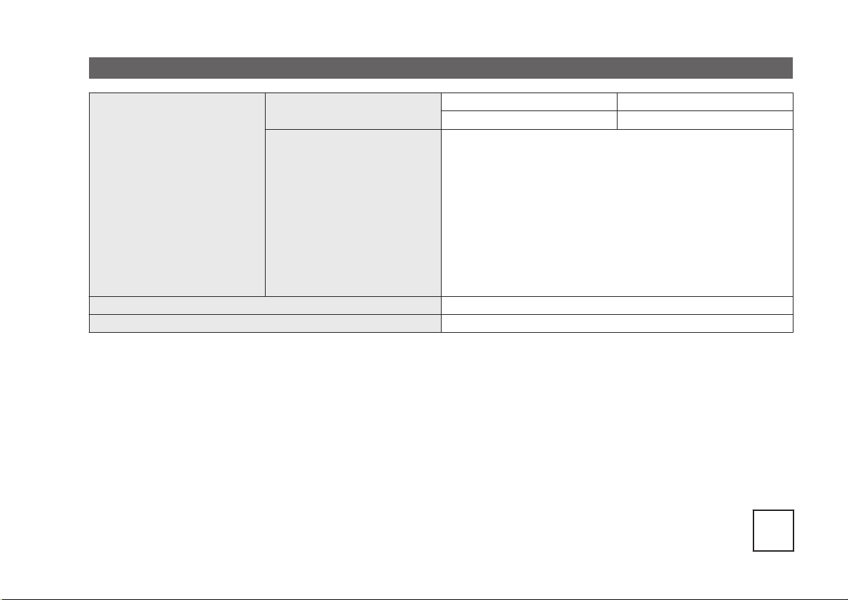
Information for station service
Fuel tank capacity
Petrol-powered vehicles
Fuel
Fuel requirements
Diesel-powered vehicles
Refer to the “General information” section for the fuel selection.
Engine oil Refer to the “Maintenance” section for the selection of engine oil.
Tyre inflation pressure Refer to the “Maintenance” section for the tyre inflation pressure.
2WD models 63 litres
4WD models 60 litres
Unleaded petrol octane number (EN228)
[2000 and 2400 models]
[3000 models]
Cetane number (EN590)
RON or higher (Vehicles to comply with the Euro 6 regula-
95
tion)
90 RON or higher (Vehicles to comply with the Euro 4 regulation)
95 RON or higher
51 or higher
E09300104110
OGFE17E1
BLO-16-000554
17
Foreword
Thank you for selecting an OUTLANDER as your new vehicle.
This
owner’s manual will add to your understanding and full enjoyment of
the many fine features of this vehicle.
It contains information prepared to acquaint you with the proper way to operate and maintain your vehicle for the utmost in driving pleasure.
MITSUBISHI MOTORS Europe B.V. reserves the right to make changes in
design and specifications and/or to make additions to or improvements in
this product without obligation to install them on products previously manufactured.
It is an absolute requirement for the driver to strictly observe all laws and
regulations concerning vehicles.
This owner’s manual has been written in compliance with such laws and regulations, but some of the contents may become contradictory with later
amendment of the laws and regulations.
Please leave this owner’s manual in this vehicle at time of resale. The next
owner will appreciate having access to the information contained in this
owner’s manual.
Repairs to your vehicle:
Vehicles in the warranty period:
All warranty repairs must be carried out by a MITSUBISHI MOTORS Authorized Service Point.
Vehicles outside the warranty period:
Where the vehicle is repaired is at the discretion of the owner.
E09200106689
Throughout this owner’s manual the words WARNING
appear.
These serve as reminders to be especially careful. Failure to follow instructions could result in personal injury or damage to your vehicle.
and CAUTION
WARNING
indicates a strong possibility of severe personal injury or death if instructions are not followed.
CAUTION
means hazards or unsafe practices that could cause minor personal injury or damage to your vehicle.
You will see another important symbol:
NOTE: gives helpful information.
*: indicates optional equipment.
may differ according to the sales classification; refer
It
to the sales catalogue.
Abbreviations used in this owner’s manual:
LHD: Left-Hand Drive
RHD: Right-Hand Drive
: Manual Transmission
M/T
A/T: Automatic Transmission
CVT: Continuously Variable Transmission
The symbol used on the vehicles:
: See owner’s manual
© 2016 Mitsubishi Motors Corporation
Table of contents
Overview/Quick guide
General information
Locking and unlocking
Seats and seat belts
Instruments and controls
Starting and driving
For pleasant driving
For emergencies
Vehicle care
Maintenance
Specifications
Alphabetical index
Declaration of Conformity
1
2
3
4
5
6
7
8
9
10
11
12
13
OGFE17E1
Instruments and controls
1
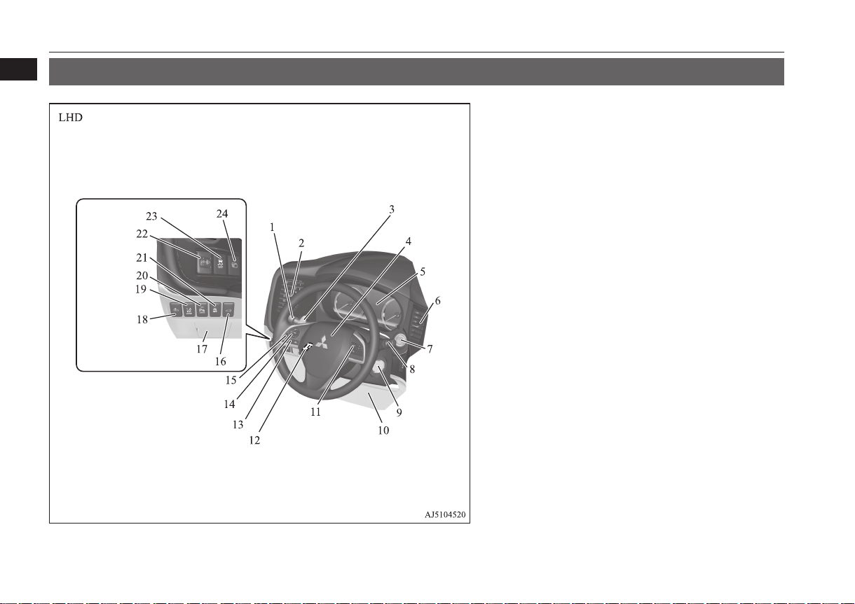
Instruments and controls
E08500101707
1. Combination headlamps and dipper switch p. 5-61
Automatic high-beam system switch* p. 5-64
Turn-signal lever p. 5-72
Front fog lamp switch* p. 5-74
Rear fog lamp switch p. 5-74
2. Driver’s ventilators p. 7-02
3. Shift paddles* p. 6-45, 6-51
4. Supplemental restraint system - airbag (for driver’s seat) p. 4-27,
4-32
Horn switch p. 5-82
5. Instruments p. 5-02
6. Driver’s ventilators p. 7-02
7. Engine switch* p. 6-18
8. Windscreen wiper and washer switch p. 5-75
Rear window wiper and washer switch p. 5-78
Headlamp washer switch* p. 5-79
9. Ignition switch* p. 6-16
10. Supplemental restraint system (SRS) - front knee airbag (for driver’s seat)* p. 4-32
11. Cruise control switch* p. 6-76, 6-86
12. Steering wheel height and reach adjustment lever p. 6-11
13.
Bluetooth® 2.0 interface* p. 7-48
14. Steering wheel audio remote control switches* p. 7-25
[For DISPLAY AUDIO, Smartphone Link Display Audio and
MMCS, refer to the separate owner’s manuals.]
15. Camera switch* p. 6-144
16. Driver’s side electric tailgate switch* p. 3-26
17. Fuse box p. 10-18
18. Forward collision mitigation system (FCM) and Ultrasonic misacceleration Mitigation System ON/OFF switch* p. 6-102
19. Lane departure warning (LDW) switch* p. 6-120
20. Sonar switch* p. 6-132
21. Auto Stop & Go (AS&G) OFF switch* p. 6-36
22. Headlamp levelling switch* p. 5-69
23. Active stability control (ASC) OFF switch* p. 6-74
24. Multi information display switch* p. 5-05
1-02
Overview/Quick guide
OGFE17E1
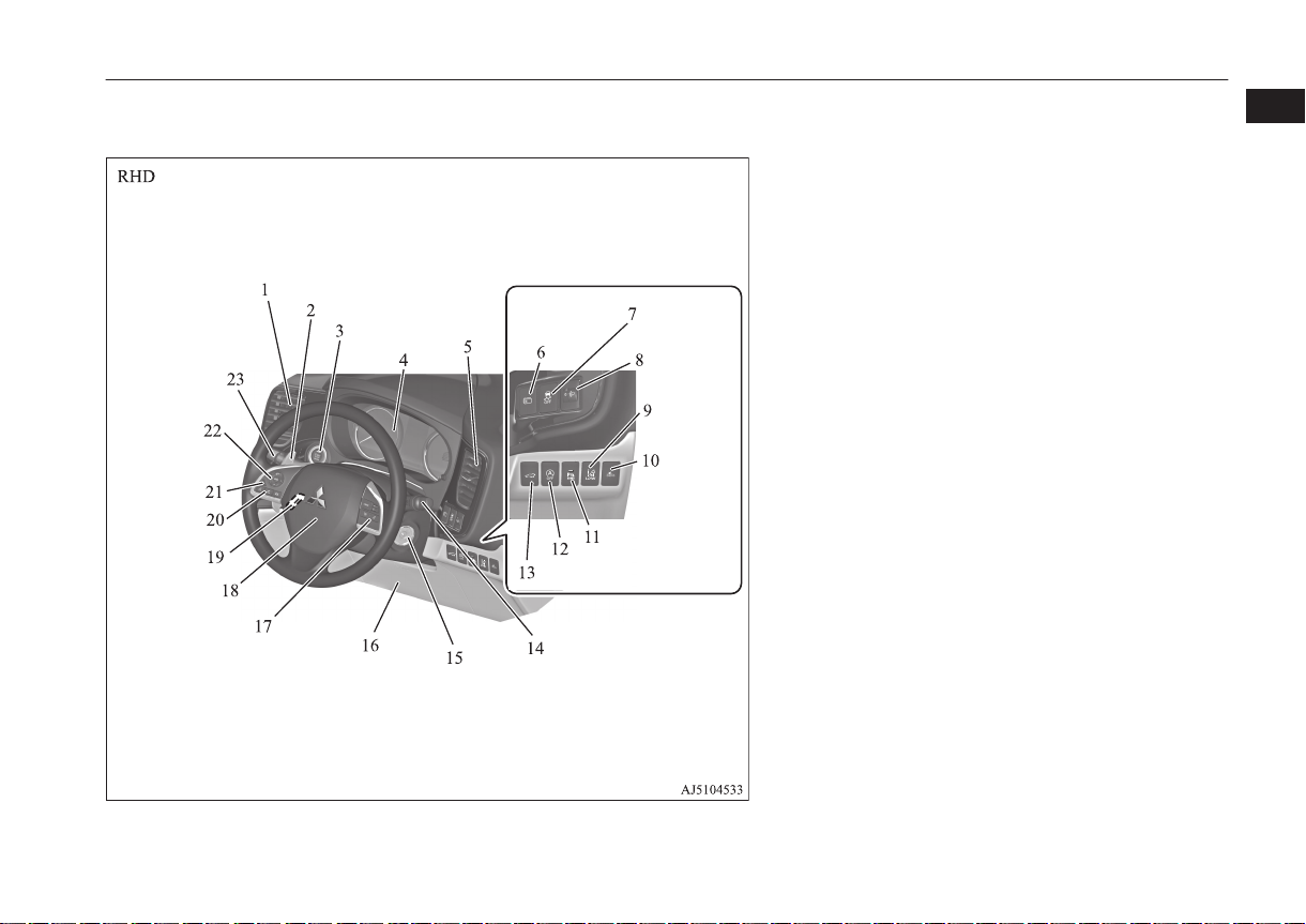
Instruments and controls
1. Driver’s ventilators p. 7-02
2. Shift paddles* p. 6-45, 6-51
3. Engine switch* p. 6-18
4. Instruments p. 5-02
5. Driver’s ventilators p. 7-02
6. Multi information display switch* p. 5-05
7. Active stability control (ASC) OFF switch p. 6-74
8. Headlamp levelling switch* p. 5-69
9. Lane departure warning (LDW) switch* p. 6-120
10. Forward collision mitigation system (FCM) and Ultrasonic misacceleration Mitigation System ON/OFF switch* p. 6-102
11. Sonar switch* p. 6-132
12. Auto Stop & Go (AS&G) OFF switch* p. 6-36
13. Driver’s side electric tailgate switch* p. 3-26
14. Windscreen wiper and washer switch p. 5-75
Rear window wiper and washer switch p. 5-78
Headlamp washer switch* p. 5-79
15. Ignition switch* p. 6-16
16. Supplemental restraint system (SRS) - front knee airbag (for driver’s seat)* p. 4-32
17. Cruise control switch p. 6-76, 6-86
18. Supplemental restraint system - airbag (for driver’s seat) p. 4-27,
4-32
Horn switch p. 5-82
19. Steering wheel height and reach adjustment lever p. 6-11
20.
Bluetooth® 2.0 interface* p. 7-48
21. Camera switch* p. 6-144
22. Steering wheel audio remote control switches* p. 7-25
[For DISPLAY AUDIO, Smartphone Link Display Audio and
MMCS, refer to the separate owner’s manuals.]
23. Combination headlamps and dipper switch p. 5-61
Automatic high-beam system switch* p. 5-64
Turn-signal lever p. 5-72
Front fog lamp switch* p. 5-74
Rear fog lamp switch p. 5-74
1
OGFE17E1
Overview/Quick guide
1-03
Instruments and controls
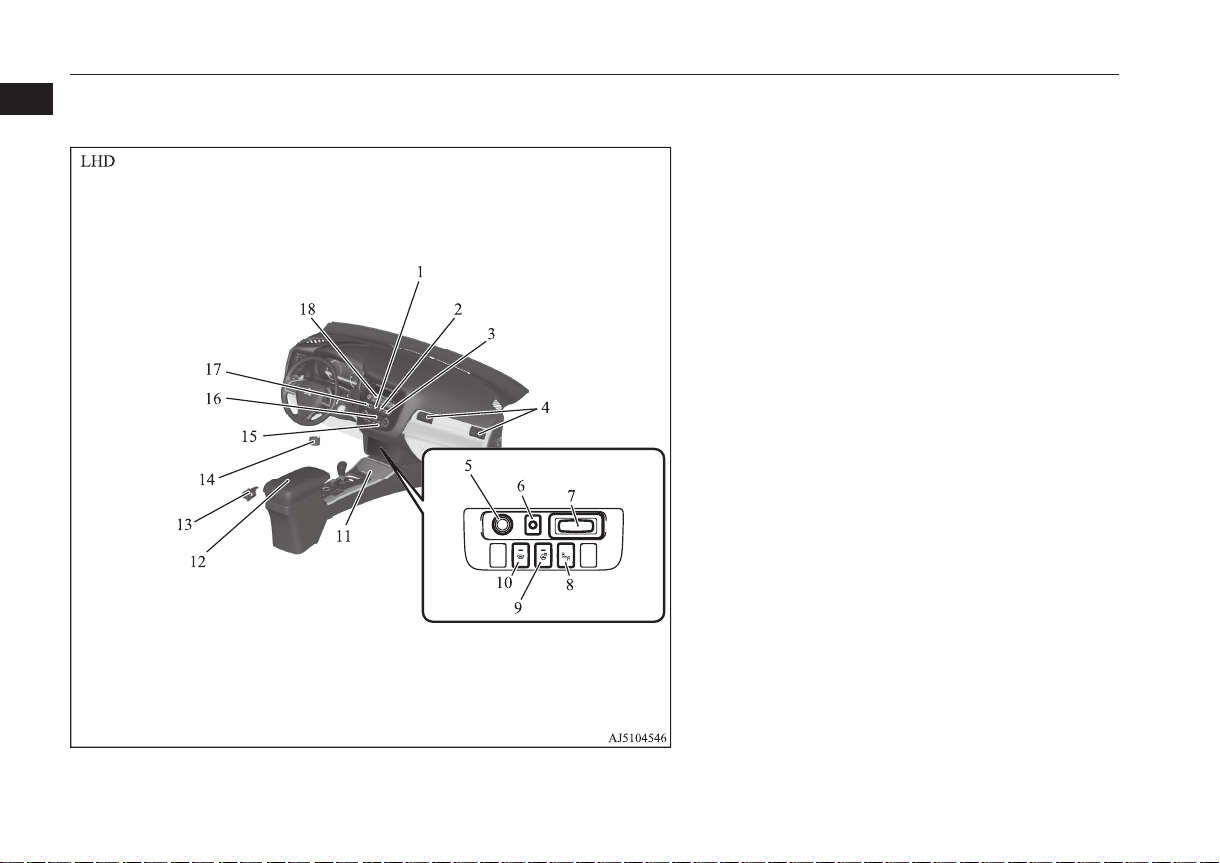
1
1. Hazard warning flasher switch p. 5-73
2. ECO mode switch* p. 5-73
3. Front passenger’s airbag indicator p. 4-30
4. Passenger’s ventilators p. 7-02
5. Accessory socket* p. 7-74
Cigarette lighter* p. 7-73
6. Electric tailgate power switch* p. 3-26
7. Key slot* p. 6-29
8. Blind Spot Warning (BSW) switch* p. 6-114
9. Heated steering wheel switch* p. 5-81
10. Heated windscreen switch* p. 5-81
11. Cup holder p. 7-80
12. Floor console box p. 7-78
Armrest
Accessory socket p. 7-74
USB input terminal* p. 7-69
13. Fuel tank filler door release lever p. 2-03
14. Bonnet release lever p. 10-04
15. Rear window demister switch p. 5-80
Wiper de-icer switch* p. 5-80
16. Air conditioner p. 7-03
17. Seat belt reminder p. 4-13
18. Audio* p. 7-13
MITSUBISHI Multi-Communication System (MMCS)*
Multi Around Monitor* p. 6-140
[For DISPLAY AUDIO, Smartphone Link Display Audio and
MMCS, refer to the separate owner’s manuals.]
1-04
Overview/Quick guide
OGFE17E1
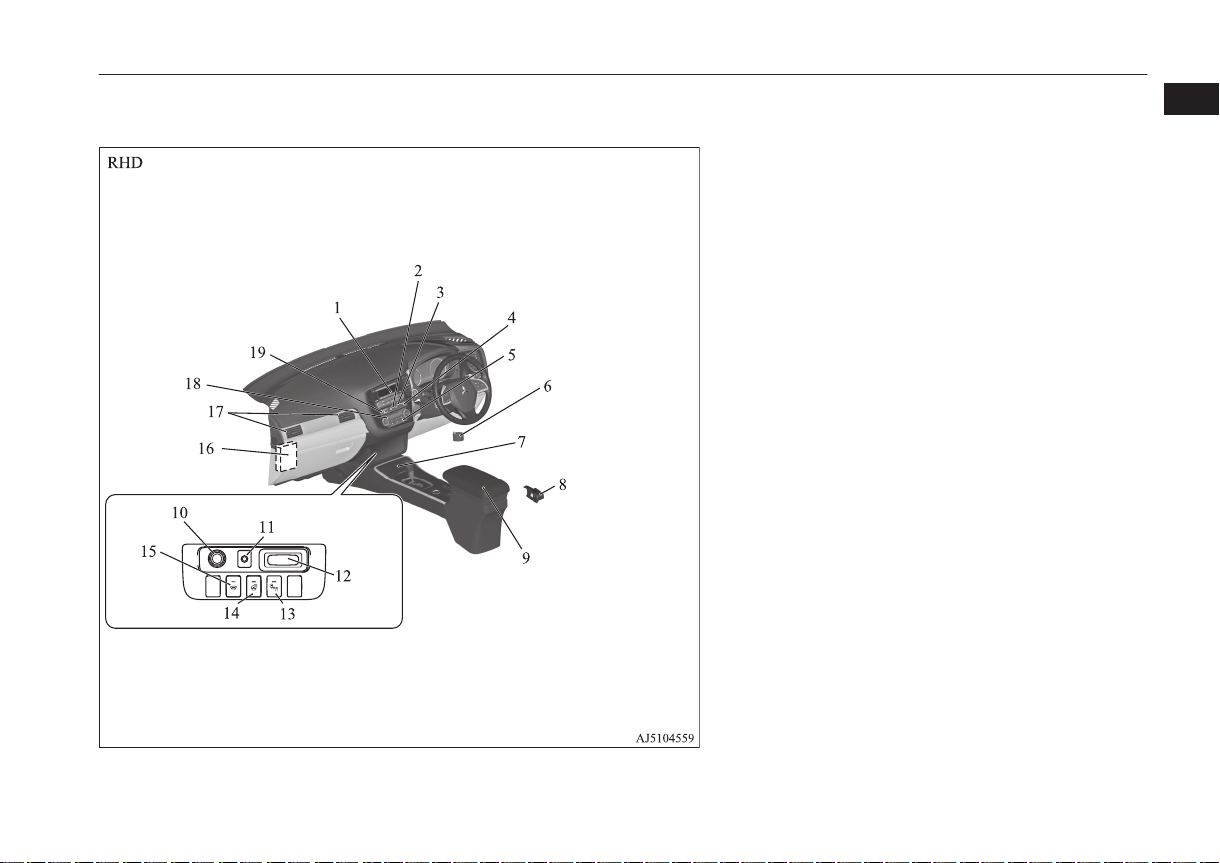
Instruments and controls
1. Audio* p. 7-13
MITSUBISHI Multi-Communication System (MMCS)*
Multi Around Monitor* p. 6-140
[For DISPLAY AUDIO, Smartphone Link Display Audio and
MMCS, refer to the separate owner’s manuals.]
2. Hazard warning flasher switch p. 5-73
3. ECO mode switch p. 5-73
4. Front passenger’s airbag indicator p. 4-30
5. Rear window demister switch p. 5-80
Wiper de-icer switch* p. 5-80
6. Bonnet release lever p. 10-04
7. Cup holder p. 7-80
8. Fuel tank filler door release lever p. 2-03
9. Floor console box p. 7-78
Armrest
Accessory socket p. 7-74
USB input terminal* p. 7-69
10. Accessory socket p. 7-74
11. Electric tailgate power switch* p. 3-26
12. Key slot* p. 6-29
13. Blind Spot Warning (BSW) switch* p. 6-114
14. Heated steering wheel switch* p. 5-81
15. Heated windscreen switch* p. 5-81
16. Fuse box p. 10-18
17. Passenger’s ventilators p. 7-02
18. Air conditioner p. 7-03
19. Seat belt reminder p. 4-13
1
OGFE17E1
Overview/Quick guide
1-05
Parking brake lever type Electric parking brake type
Instruments and controls
1
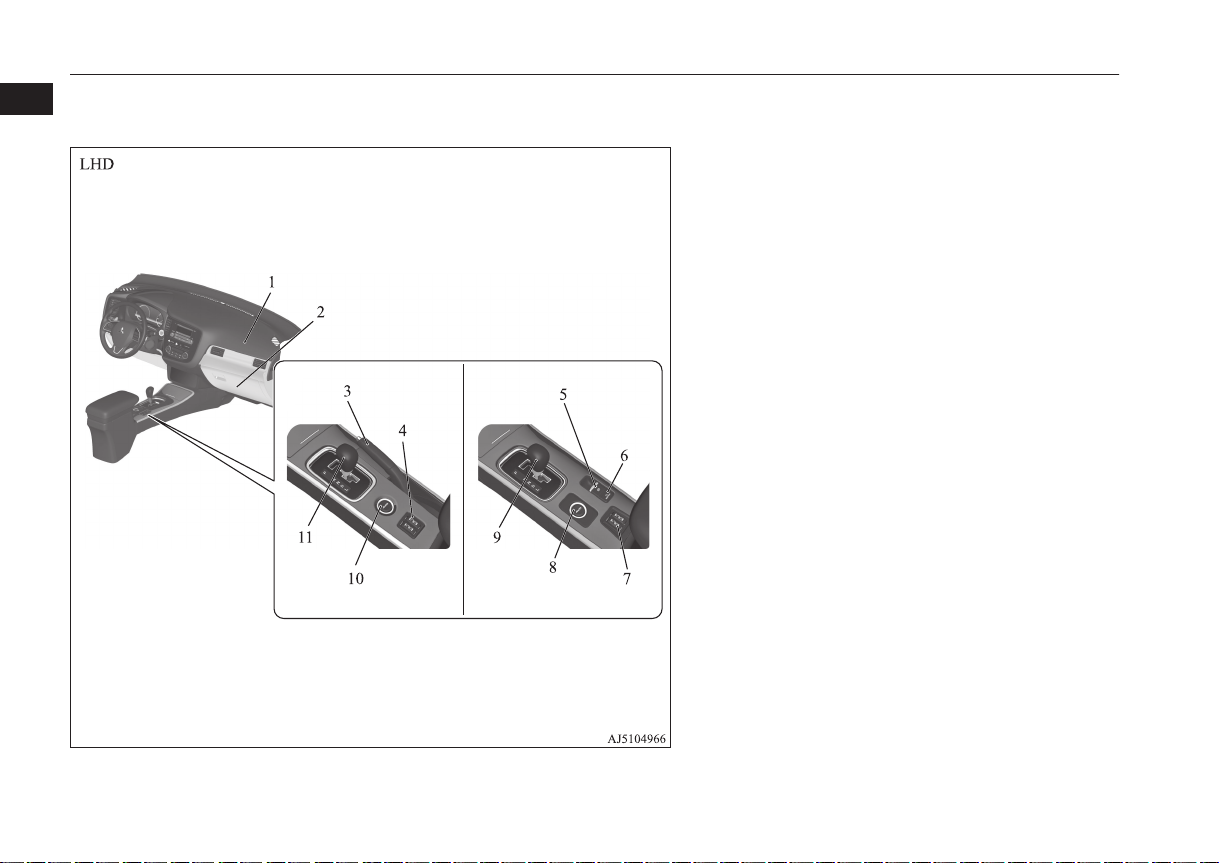
1. Supplemental restraint system (SRS) - airbag (for front passenger’s seat) p. 4-27, 4-32
2. Glove box p. 7-77
Card holder p. 7-77
3. Parking brake lever p. 6-06
4. Heated seat switch* p. 4-04
5. Electric parking brake switch p. 6-07
6. Brake auto hold switch p. 6-65
7. Heated seat switch* p. 4-04
8. Drive mode selector* p. 6-55
S-AWC drive mode-selector* p. 6-59
9. Selector lever p. 6-40, 6-47
10. Drive mode selector* p. 6-55
S-AWC drive mode-selector* p. 6-59
11. Gearshift lever* p. 6-37
Selector lever* p. 6-47
1-06
Overview/Quick guide
OGFE17E1
Parking brake lever type Electric parking brake type
Instruments and controls
1
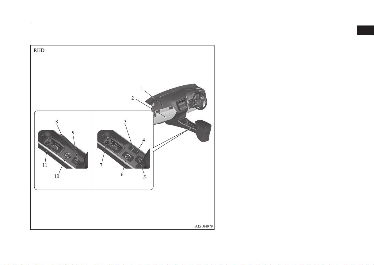
1. Supplemental restraint system (SRS) - airbag (for front passenger’s seat) p. 4-27, 4-32
2. Glove box p. 7-77
Card holder p. 7-77
3. Electric parking brake switch p. 6-07
4. Brake auto hold switch p. 6-65
5. Heated seat switch* p. 4-04
6. Drive mode selector* p. 6-55
S-AWC drive mode-selector* p. 6-59
7. Selector lever p. 6-40, 6-47
8. Parking brake lever p. 6-06
9. Heated seat switch* p. 4-04
10. Drive mode selector* p. 6-55
S-AWC drive mode-selector* p. 6-59
11. Gearshift lever* p. 6-37
Selector lever* p. 6-47
OGFE17E1
Overview/Quick guide
1-07
1
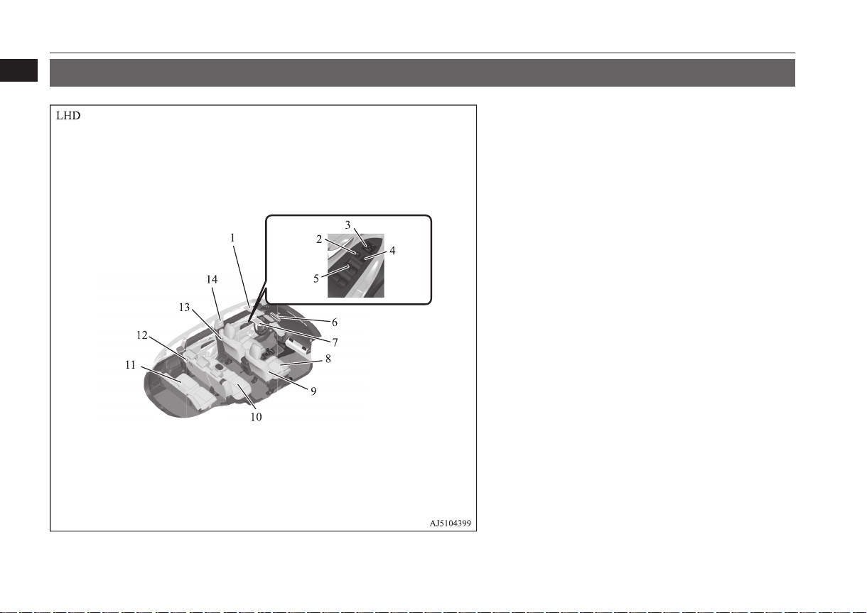
Interior
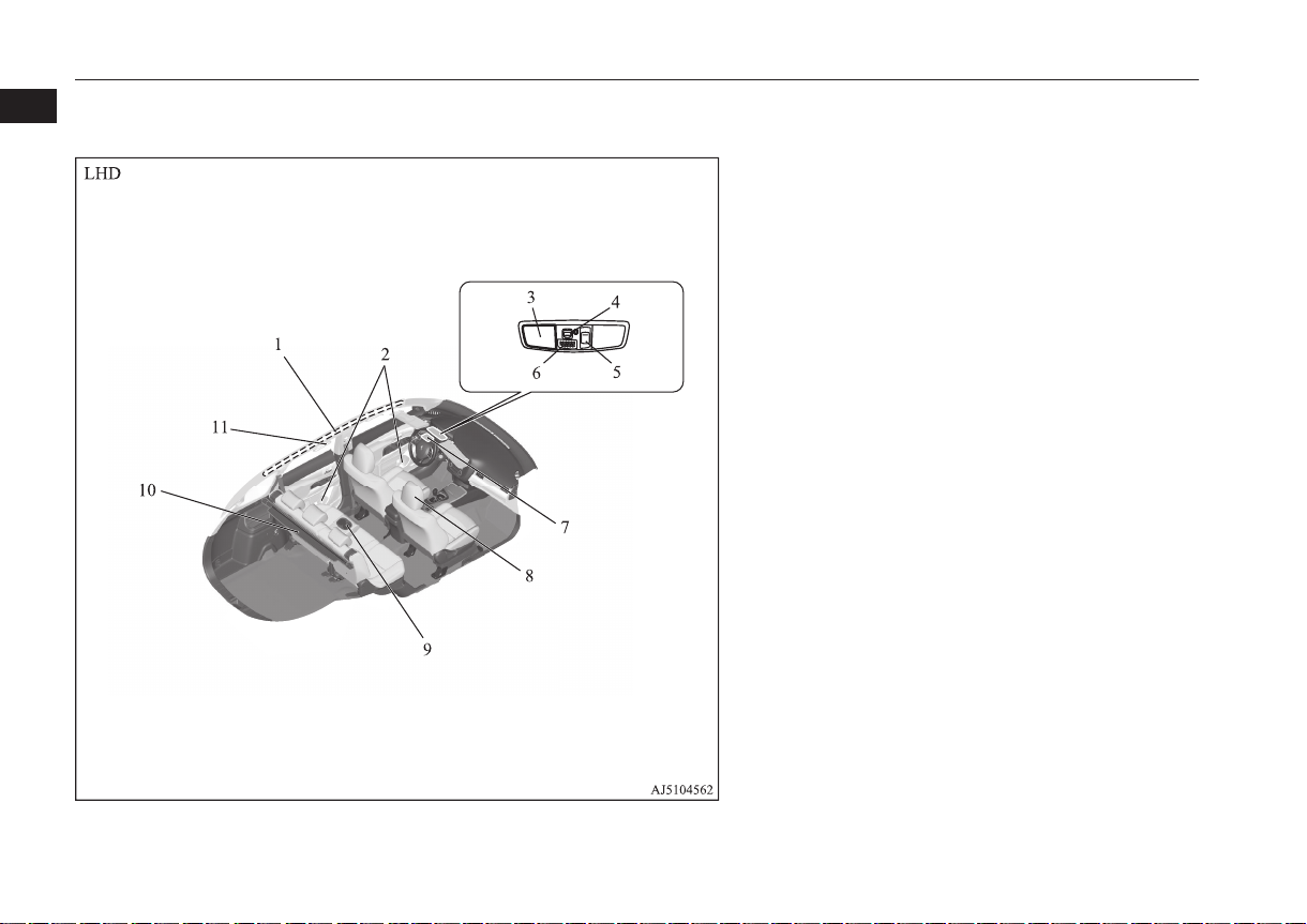
Interior
E08500201463
1. Sun visors p. 7-72
Vanity mirror p. 7-72
Card holder p. 7-72
2. Lock switch p. 3-41
3. Electric remote-controlled outside rear-view mirrors switch
p. 6-13
4. Central door lock switch p. 3-22
5. Electric window control switch p. 3-41
6. Inside rear-view mirror p. 6-11
Multi Around Monitor* p. 6-140
7. Sunglasses holder* p. 7-80
8. Front seats p. 4-04
9. Supplemental restraint system (SRS) - side airbag (for front seat)*
p. 4-35, 4-27
10. Second seat p. 4-05
11. Third seats (7 persons) p. 4-06
12. Luggage room lamp p. 7-76
13. Room lamp (rear) p. 7-75
14. Adjustable seat belt anchor p. 4-15
Seat belts p. 4-11
1-08
Overview/Quick guide
OGFE17E1
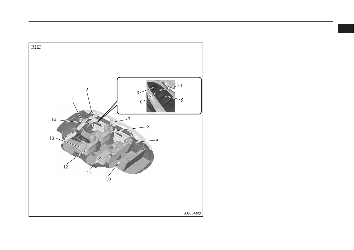
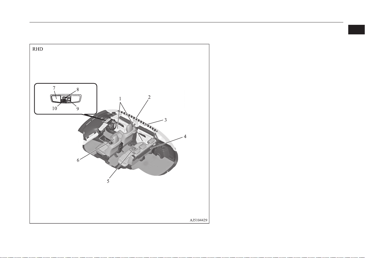
Interior
1. Inside rear-view mirror p. 6-11
Multi Around Monitor* p. 6-140
2. Sun visors p. 7-72
Vanity mirror p. 7-72
Card holder p. 7-72
3. Electric remote-controlled outside rear-view mirrors switch
p. 6-13
4. Central door lock switch p. 3-22
5. Electric window control switch p. 3-41
6. Lock switch p. 3-41
7. Adjustable seat belt anchor p. 4-15
Seat belts p. 4-11
8. Room lamp (rear) p. 7-75
9. Luggage room lamp p. 7-76
10. Third seats (7 persons) p. 4-06
11. Second seat* p. 4-05
12. Supplemental restraint system (SRS) - side airbag (for front seat)*
p. 4-35, 4-27
13. Front seats p. 4-04
14. Sunglasses holder* p. 7-80
1
OGFE17E1
Overview/Quick guide
1-09
Interior
1
1. Supplemental restraint system (SRS) - curtain airbag* p. 4-27,
4-35
2. Bottle holder p. 7-81
3. Map & room lamps (front) p. 7-75, 7-76
4. Downlight p. 7-75
5. Sunroof switch* p. 3-43
6. Hands-free microphone* p. 7-49
7. ERA-GLONASS* p. 8-02
8. Head restraints p. 4-06
9. Armrest p. 4-05
Cup holder p. 7-80
10. Cargo area cover* p. 7-81
11. Assist grips p. 7-83
Coat hook p. 7-83
1-10
Overview/Quick guide
OGFE17E1
1. Bottle holder p. 7-81
2. Supplemental restraint system (SRS) - curtain airbag* p. 4-27,
4-35
3. Assist grips p. 7-83
Coat hook p. 7-83
4. Cargo area cover* p. 7-81
5. Armrest p. 4-05
Cup holder p. 7-80
6. Head restraints p. 4-06
7. Map & room lamps (front) p. 7-75, 7-76
8. Downlight p. 7-75
9. Sunroof switch* p. 3-43
10. Hands-free microphone* p. 7-49
Interior
1
OGFE17E1
Overview/Quick guide
1-11
Luggage area
1
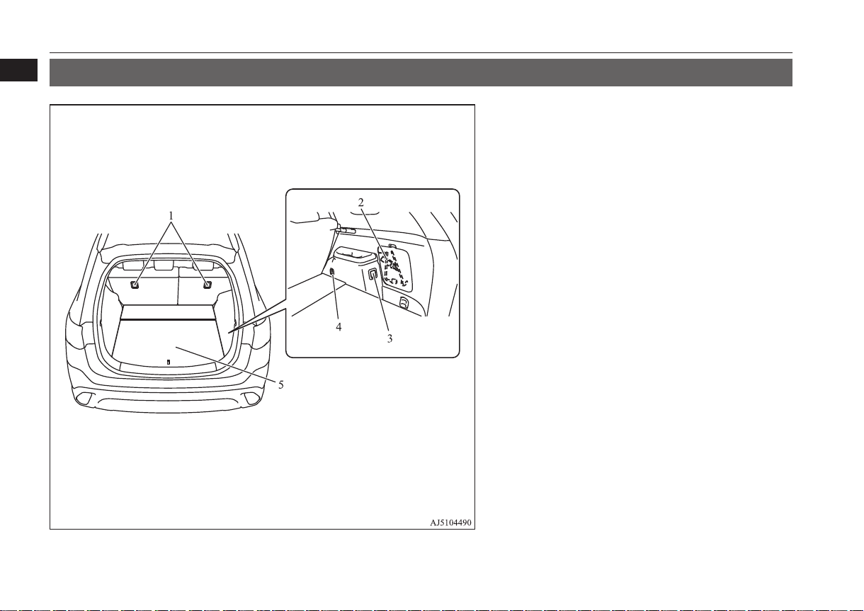
Luggage area
E08500301262
1. Tether anchorages for child restraint system* p. 4-25
2. Jack p. 8-11
Tools p. 8-11
3. Accessory socket p. 7-74
4. Luggage hooks p. 7-83
5. Luggage floor box* p. 7-78
1-12
Overview/Quick guide
OGFE17E1
Halogen headlamps type LED headlamps type
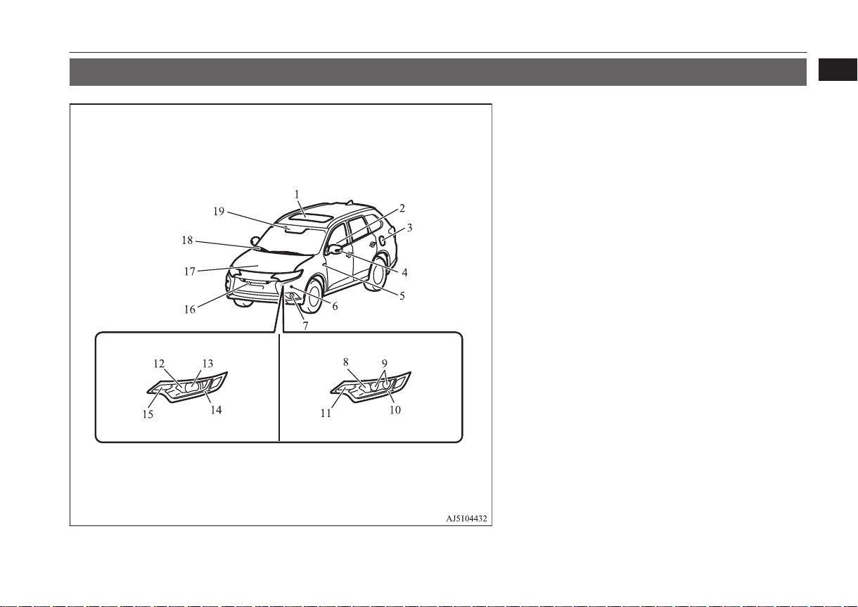
Outside (Front)
Outside (Front)
1
E08500401856
1. Sunroof* p. 3-43
2. Electric window control p. 3-41
3. Fuel tank filler p. 2-03
4. Outside rear-view mirror p. 6-13
Side turn-signal lamps* p. 5-72, 10-25
Side-view camera* p. 6-140
5. Side turn-signal lamps* p. 5-72, 10-25
6. Ultrasonic misacceleration Mitigation System* p. 6-108
Parking sensors* p. 6-134
7. Front fog lamps* p. 5-74, 10-25, 10-29
8. Headlamps, high-beam p. 5-61, 10-25, 10-28
9. Headlamps, low beam p. 5-61, 10-25
10. Position lamps p. 5-61, 10-25
Daytime running lamps p. 5-64, 10-25
11. Front turn-signal lamps p. 5-72, 10-25, 10-28
12. Headlamps, high-beam p. 5-61, 10-25, 10-28
13. Headlamps, low beam p. 5-61, 10-25, 10-27
14. Position lamps p. 5-61, 10-25
Daytime running lamps p. 5-64, 10-25
15. Front turn-signal lamps p. 5-72, 10-25, 10-28
16. Front view camera* p. 6-140
17. Bonnet p. 10-04
18. Windscreen wipers p. 5-75
19. Sensor* [for Automatic high-beam system, Forward Collision Mitigation System (FCM) and Lane Departure Warning (LDW)]
p. 5-64, 6-97, 6-119
Rain sensor p. 5-75
OGFE17E1
Overview/Quick guide
1-13
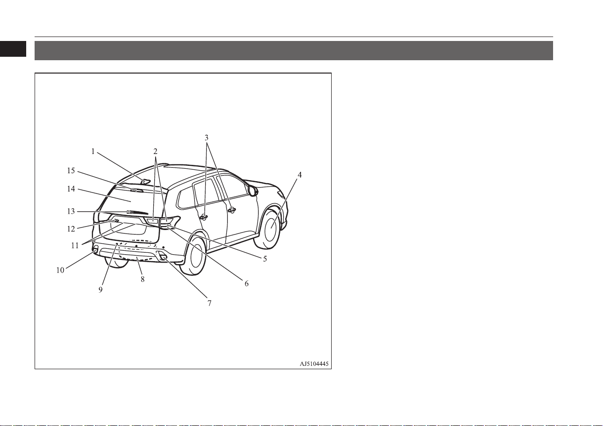
Outside (Rear)
1
Outside (Rear)
E08500401869
1. Antenna
2. Tail lamps p. 5-61, 10-25,10-31
3. Keyless entry system* p. 3-04
Keyless operation system* p. 3-08
Locking and unlocking the doors p. 3-20
4. Tyre p. 10-12
Tyre pressure monitoring system (TPMS)* p. 6-123
Tyre inflation pressures p. 10-12
Changing tyres p. 8-12
Tyre rotation p. 10-13
Snow traction device (Tyre chains) p. 10-15
Size of tyres and wheels p. 11-15
5. Stop lamps p. 10-25, 10-31
6. Rear turn-signal lamps p. 5-72, 10-25, 10-31
7. Rear fog lamp (RHD vehicles) p. 5-74, 10-25, 10-30
Reversing lamps (LHD vehicles) p. 10-25, 10-30
8. Spare wheel p. 8-13
9. Ultrasonic misacceleration Mitigation System* p. 6-108
Reversing sensor system* p. 6-130
Parking sensors* p. 6-134
10. Rear fog lamp (LHD vehicles) p. 5-74, 10-25, 10-30
Reversing lamps (RHD vehicles) p. 10-25, 10-30
11. Licence plate lamps p. 5-61, 10-25, 10-32
12. Rear-view camera* p. 6-138, 6-140
13. Rear window wiper p. 5-78
14. Tailgate* p. 3-24
Electric tailgate* p. 3-26
15. High-mounted stop lamp p. 10-25
1-14
Overview/Quick guide
OGFE17E1
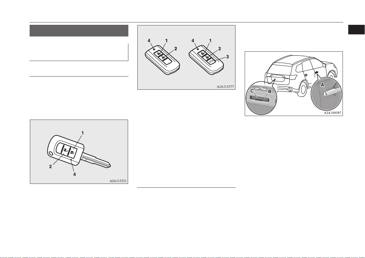
Keyless entry key
Keyless operation key
Quick guide
Quick guide
Locking and unlocking the
doors and tailgate
Keyless entry system
Press the remote control switch, and all doors
and the tailgate will be locked or unlocked as
desired.
The remote control switch will operate within
approximately 4 m from the vehicle.
E08500500010
E08500601409
1- LOCK switch
2- UNLOCK switch
3- Electric tailgate switch
4- Indication lamp
Refer to “Keyless entry system” on page
3-04
On vehicles with the electric tailgate, the tailgate can be opened automatically if you press
the electric tailgate switch (3) after unlocking
the tailgate.
Refer to “Electric tailgate*” on page 3-26
Keyless operation system*
When you are carrying the keyless operation
key and within the operating range, if you
press the driver’s or front passenger’s door
switch (A), or the tailgate switch (B) (when
locking) and the tailgate open switch (C)
(when unlocking), the doors and the tailgate
are locked/unlocked.
OGFE17E1
The operating range is approximately 70 cm
from the driver’s door switch, front passenger’s door switch and the tailgate switches.
Refer to “Keyless operation system” on
page 3-08
Overview/Quick guide
1-15
1
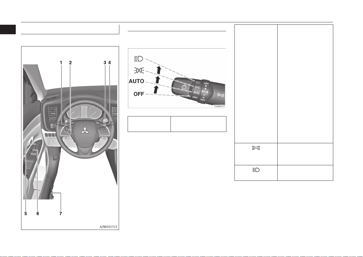
Quick guide
Around the driver’s seat
1
E08500801472
1-Combination headlamps
Rotate the switch to turn on the lamps.
OFF All lamps off {except
daytime running lamps}
AUTO With the ignition switch
or the operation mode is
in ON, head-lamps, position, tail, licence plate,
instrument panel lamps
and downlight turn on
and off automatically in
accordance with outside
light level. {Daytime
running lamps will be
turned on while the tail
lamps are off.} All
lamps turn off automatically when the ignition
switch is turned to
“OFF” position or the
operation mode is put in
OFF.
Position, tail, licence
plate, instrument panel
lamps and downlight on
Headlamps and other
lamps go on
Refer “Combination headlamps and dipper switch” on page 5-61.
1-16
Overview/Quick guide
OGFE17E1
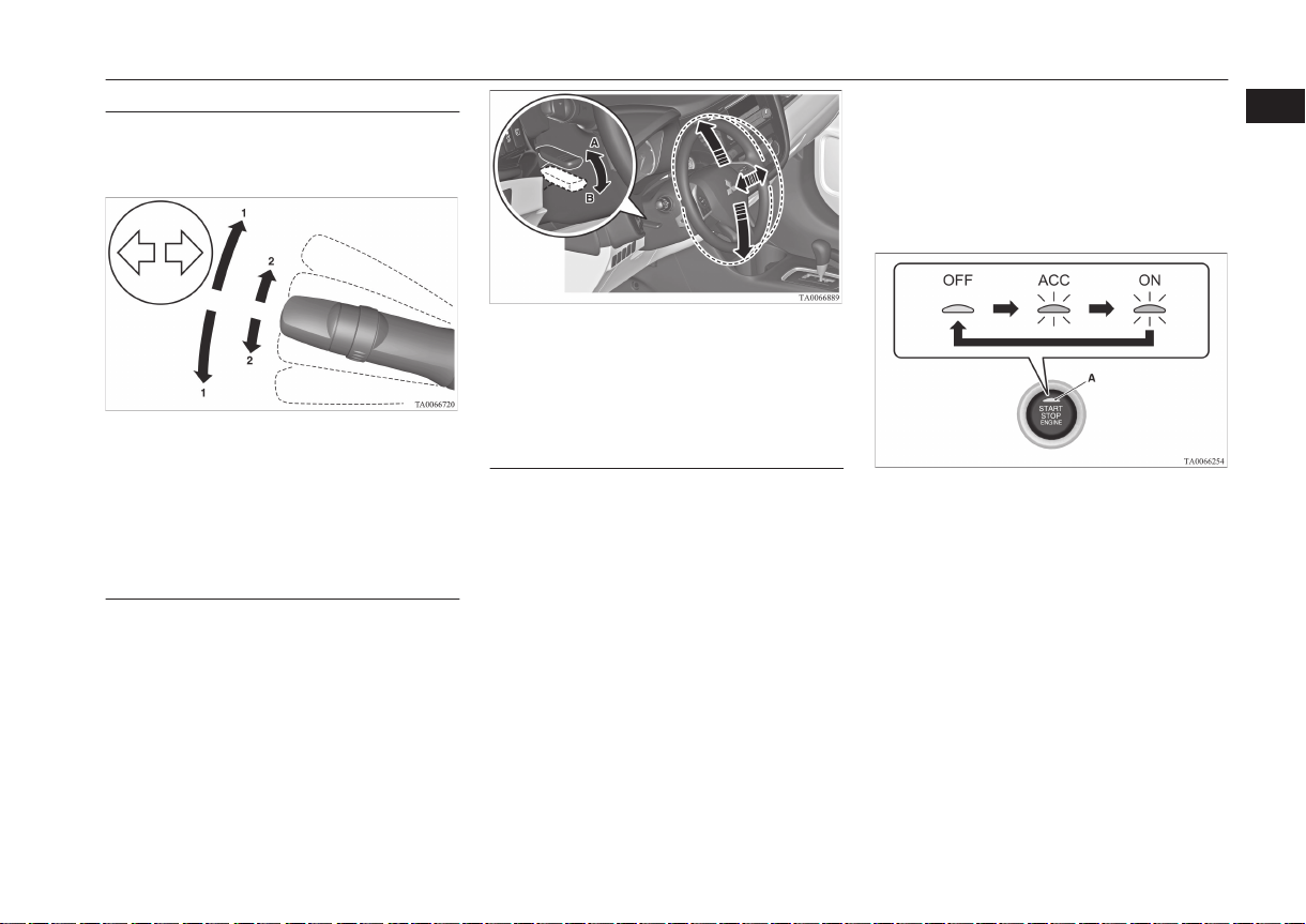
Quick guide
1-Turn-signal lever
The turn-signal lamps flash when the lever is
operated
1- Turn-signals
2- Lane-change signals
Refer to “Turn-signal lever” on page
5-72.
2-Steering wheel height and
reach adjustment
1. Release the lever while holding the
steering wheel up.
2. Adjust the steering wheel to the desired
position.
3. Securely lock the steering wheel by pulling the lever fully upward.
A- Locked
B- Release
Refer “Steering wheel height and reach
adjustment” on page 6-11.
3-Engine switch*
[For vehicles equipped with keyless operation system]
If you are carrying the keyless operation key,
you can start the engine. If you press the engine switch without depressing the brake
pedal (A/T, CVT) or the clutch pedal (M/T),
you can change the operation mode in the order of OFF, ACC, ON, OFF.
OFF- The indication lamp (A)
on the engine switch
turns off.
ACC- The indication lamp on
the engine switch illuminates orange.
ON- The indication lamp on
the engine switch illuminates green.
Refer “Engine switch” on page 6-18.
1
OGFE17E1
Overview/Quick guide
1-17
Except for vehicles equipped with the
mirror retractor switch
Vehicles equipped with the mirror
retractor switch
Quick guide
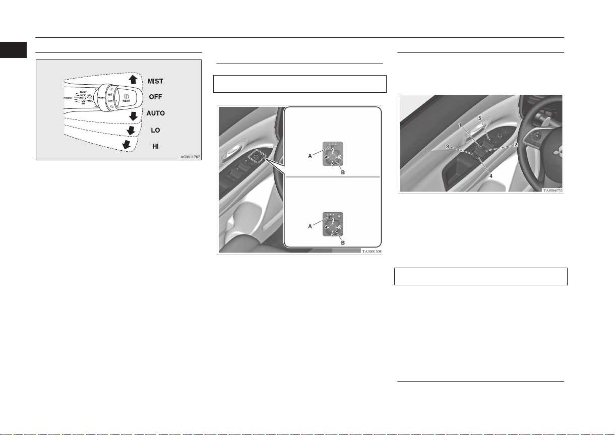
4-Wiper and washer switch
1
MIST- Misting function
The wipers will operate
once.
OFF- Off
AUTO- Auto-wiper control
The wipers will automatically operate depending on the degree
of wetness on the wind-
The washer fluid will be sprayed onto the
windscreen by pulling the lever towards you.
Refer to “Wiper and washer switch” on
page 5-75.
1-18
Overview/Quick guide
screen.
LO- Slow
HI- Fast
5-Electric remote-controlled
outside rear-view mirrors
To adjust the mirror position
L- Left outside mirror adjustment
R- Right outside mirror adjustment
1- Up
2- Down
3- Right
4- Left
5- Mirror retractor switch
Refer “Electric remote-controlled outside
rear-view mirrors” on page 6-13.
OGFE17E1
6-Electric window control
Press the switch down for opening the window, and pull the switch for closing.
1- Driver’s door window
2- Front passenger’s door window
3- Rear left door window
4- Rear right door window
5- Lock switch
Lock switch
If you press the switch (5), the passenger’s
switches cannot be operated. To cancel, press
it once again.
Refer “Electric window control” on page
3-41.
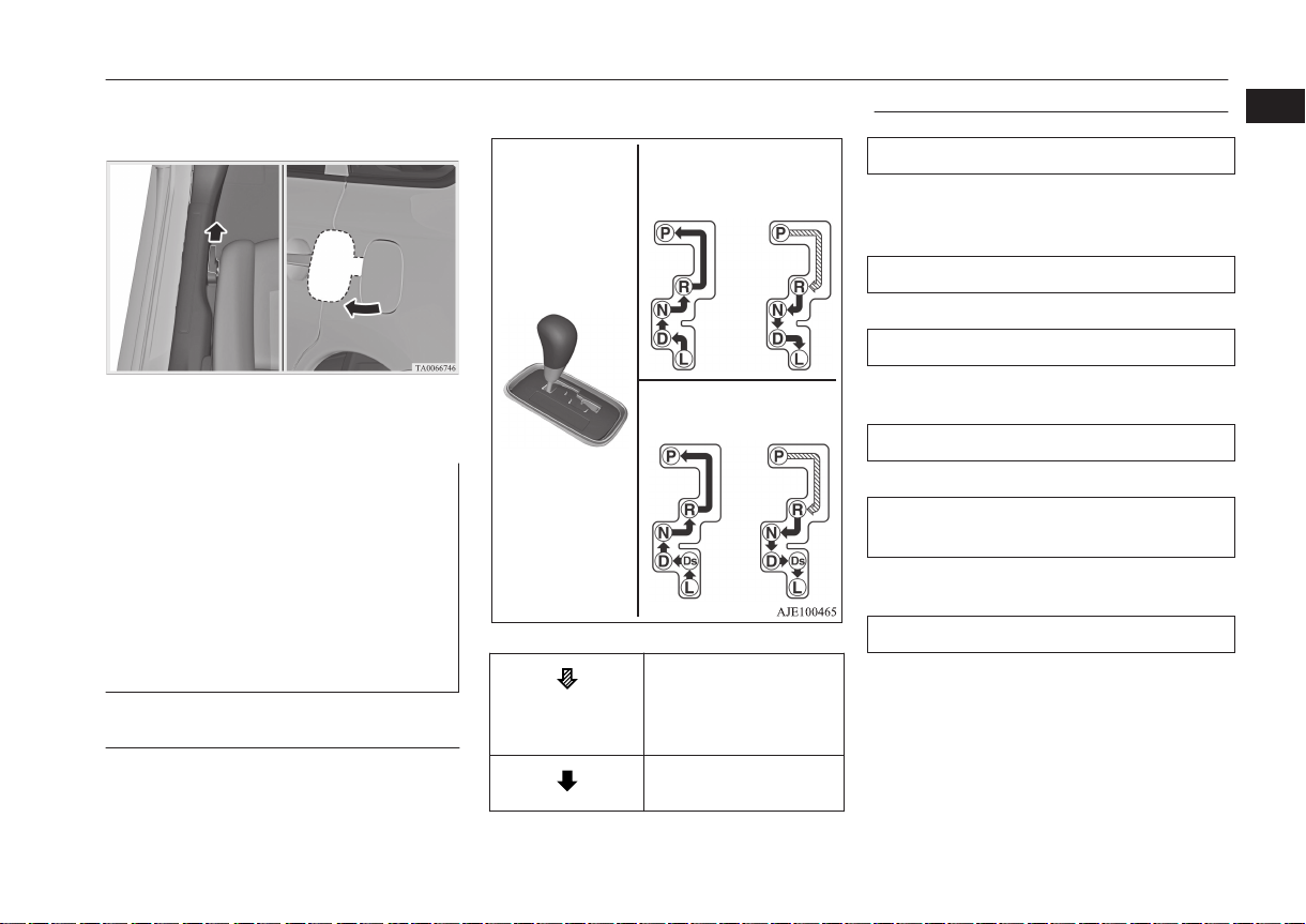
7-Fuel tank filler door release
lever
Open the fuel tank filler door.
INVECS-II 6A/T
INVECS-III 6CVT with
shift paddles
INVECS-III 6CVT
without shift paddles
Quick guide
The fuel tank filler is located on the rear left
side of your vehicle.
Refer “Filling the fuel tank” on page
2-03.
Automatic transmission INVECS-II 6A/T (Intelligent &
Innovative Vehicle Electronic
Control System II)* and Automatic transmission INVECSIII 6CVT (Intelligent & Innovative Vehicle Electronic Control System III)*
Selector lever operation
The transmission selects an optimum gear ratio automatically, depending on the speed of
the vehicle and the position of the accelerator
pedal.
E08501001093
While depressing the
brake pedal, move the
selector lever through
the gate.
Move the selector lever
through the gate.
OGFE17E1
Selector lever positions
“P” PARK
This position locks the transmission to prevent the vehicle from moving. The engine
can be started in this position.
“R” REVERSE
This position is to back up.
“N” NEUTRAL
At this position the transmission is disengaged.
“D” DRIVE
This position is for normal driving.
“Ds” (DOWNSHIFT & SPORTY DRIVING)
Use when engine braking is needed, or for
high-power sport drive.
“L” LOW
This position is for driving up very steep hills
and for engine braking at low speeds when
driving down steep hills.
Refer to “Automatic transmission INVECS-II 6A/T (Intelligent & Innovative
Vehicle Electronic Control System II)” on
page 6-40.
Overview/Quick guide
1-19
1
Type 1
Type 2
Quick guide
1
Refer to “Automatic transmission INVECS-III 6CVT (Intelligent & Innovative
Vehicle Electronic Control System III)” on
page 6-47.
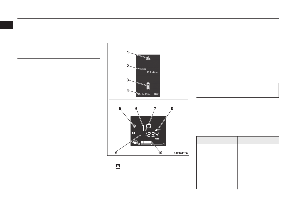
Multi information display
Always stop the vehicle in a safe place before
operating.
1-20
Overview/Quick guide
E08501201255
The following information is included on the
multi information display: odometer, tripmeter, average fuel consumption etc.
1-
mark display screen ® p. 5-07
2- Information screen ® p. 5-05
Interrupt display screen ® p. 5-06
3- Door ajar warning display screen
® p. 5-07
4- Odometer ® p. 5-09
OGFE17E1
5- Frozen road warning ® p. 5-24
6- Gearshift indicator* ® p. 6-37
7- Selector lever position display*
® p. 6-42, 6-49
8- Service reminder ® p. 5-09
9- Information display ® p. 5-21
10- Fuel remaining display ® p. 5-24
Refer “Multi information display - Type
1” on page 5-03 or “Multi information
display - Type 2” on page 5-20.
Electronically controlled 4WD
system*
E08501701074
The electronically controlled 4WD is a system that improves acceleration performance
and stability performance by controlling
front-rear distribution of driving torque with
operating the electronic control coupling arranged in the rear differential assembly.
Drive mode Function
4WD ECO This mode is for eco-
nomical driving.
Usually, driving
mode is 2WD for
economy but the performance of 4WD is
produced according
to the slip of a wheel.
Quick guide
Drive mode Function
4WD AUTO This mode is for au-
tomatically controlling the distribution
of driving torque to
all four wheels according to the driving conditions.
4WD LOCK This mode is for
driving in slippery
conditions such as on
snow-covered roads
or sand.
The large amount of
driving torque that is
applied to the rear
tyres enables getting
out of slippery areas
and powerful driving
is possible across all
ranges.
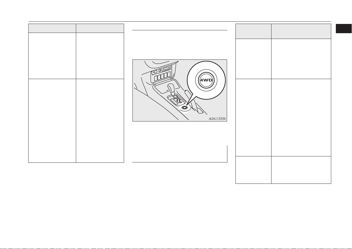
Drive mode-selector
The drive mode can be switched by press the
switch while the ignition switch is in the
“ON” position or the operation mode in ON.
Refer to “Electronically controlled 4WD
system” on page 6-55.
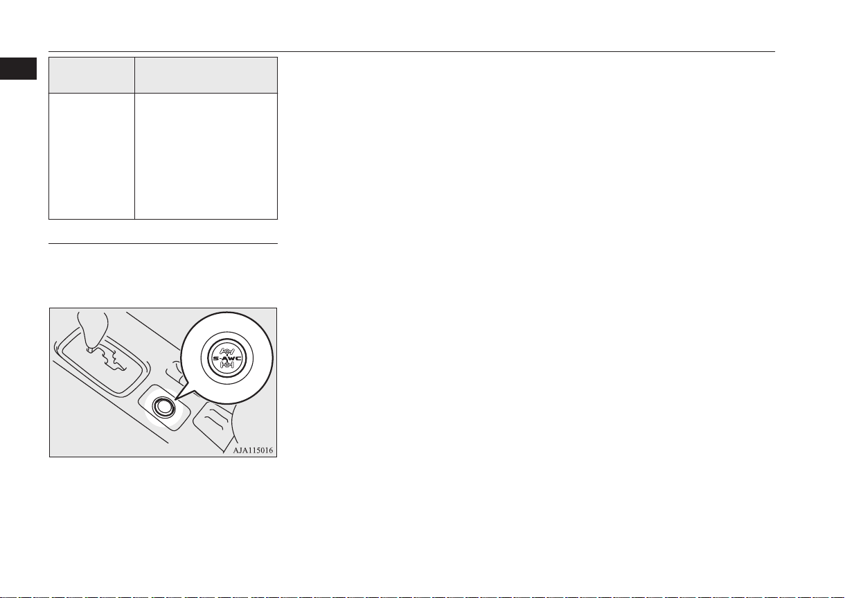
S-AWC (Super-All Wheel Control)*
E08501900053
S-AWC is an integrated vehicle dynamics
control system that helps enhance driving
performance, cornering performance, and vehicle stability over a wide range of driving
conditions through integrated management of
the electronically controlled 4WD, the AYC
(Active Yaw Control), the ABS and the ASC.
S-AWC con-
trol mode
AWC ECO High fuel efficiency mode.
This mode is ordinary
driven on efficient 2WD
and provides 4WD performance on wheel slipping conditions.
NORMAL Normal mode applied to
dry pavement road and wet
road, etc.
This mode controls driving/ braking torque between front right and front
left wheel and between
front and rear wheel according to the driving condition, and achieves low
fuel consumption and agile
driving.
SNOW This mode is chiefly suita-
ble for the snow road.
Stability improves on a
slippery road.
Function
1
OGFE17E1
Overview/Quick guide
1-21
Quick guide
1
S-AWC con-
trol mode
LOCK High traction mode.
This mode excels at rough
road driving and escape
from stuck conditions, in
addition, realizes strong
4WD driving from low
speed to high speed on ordinary road.
Function
S-AWC drive mode-selector
The drive mode can be switched by press the
switch while the ignition switch is in the
“ON” position or the operation mode in ON.
Refer to “S-AWC (Super-All Wheel Control)” on page 6-57.
1-22
Overview/Quick guide
OGFE17E1

General information
Fuel selection...................................................................................... 2-02
Filling the fuel tank.............................................................................2-03
Installation of accessories................................................................... 2-04
Modification/alterations to the electrical or fuel systems................... 2-05
Genuine parts...................................................................................... 2-05
Safety and disposal information for used engine oil...........................2-06
Disposal information for used batteries.............................................. 2-06
2
OGFE17E1
Fuel selection
Fuel selection
2
Recommended
fuel
For petrol-powered vehicles, the use of lea-
l
ded fuel can result in serious damage to the
engine and catalytic converter. Do not use
leaded fuel.
Petrol-powered vehicles
Unleaded petrol octane
number (EN228)
[2000 and 2400 models]
95 RON or higher (Vehicles to comply with the
Euro 6 regulation)
90 RON or higher (Vehicles to comply with the
Euro 5 regulation)
[3000 models]
95 RON or higher
Diesel-powered vehicles
Cetane number (EN590)
51 or higher
CAUTION
E00200104754
CAUTION
Diesel-powered vehicles are designed to use
l
only diesel fuel that meets the EN590 standard.
Use of any other type of diesel fuel (bio diesel, methylester, etc.) would adversely affect
the engine’s performance and durability.
NOTE
Petrol-powered vehicles have the knock con-
l
trol system so that you can use unleaded petrol 90 RON as an emergent measure in case
unleaded petrol 95 RON or higher is not
available on journey, etc.
In such a case, you don’t need to adjust the
engine specially. In case of using unleaded
petrol 90 RON, the engine performance level is reduced.
Due to the separation of paraffin, the fluidity
l
of the fuel decreases considerably as the
temperature falls.
Because of this fact there are two kinds of
fuel: “summer” and “winter”.
This must be considered in winter use.
Select either of the two kinds of fuel in accordance with ambient temperature.
Above -5 °C: “Summer” diesel
Below -5 °C: “Winter” diesel
When travelling abroad, find out in advance
about the fuels served in local service stations.
NOTE
In petrol-powered vehicles, repeatedly driv-
l
ing short distances at low speeds can cause
deposits to form in the fuel system and engine, resulting in poor starting and poor acceleration. If these problems occur, you are
advised to add a detergent additive to the
petrol when you refuel the vehicle. The additive will remove the deposits, thereby returning the engine to a normal condition. Be sure
to use a MITSUBISHI MOTORS GENUINE FUEL SYSTEM CLEANER. Using an
unsuitable additive could make the engine
malfunction. For details, please contact your
MITSUBISHI MOTORS Authorized Service Point.
Poor quality petrol can cause problems such
l
as difficult starting, stalling, engine noise
and hesitation. If you experience these problems, try another brand and/or grade of petrol.
If the check engine warning lamp flashes,
have the system checked as soon as possible
at a MITSUBISHI MOTORS Authorized
Service Point.
2-02
General information
OGFE17E1
Filling the fuel tank
NOTE
In diesel-powered vehicles, poor-quality die-
l
sel fuel can cause deposits form in the injector, resulting in black smoke and rough
idling.
If these problems occur, you are advised to
add a cleaning additive to the diesel fuel
when you refuel the vehicle.
The additive will break up and remove the
deposits, thereby returning the engine to a
normal condition.
Be sure to use a MITSUBISHI MOTORS
GENUINE DIESEL FUEL SYSTEM
CLEANER. Using an unsuitable additive
could make the engine malfunction. For details, please contact your MITSUBISHI
MOTORS Authorized Service Point.
E10 type petrol
The petrol engines are compatible with the
E10 type petrol (containing 10 % ethanol)
conforming to European standards EN 228.
E00203200019
CAUTION
Do not use more than 10 % concentration of
l
ethanol (grain alcohol) by volume.
Use of more than 10 % concentration may
lead to damage to your vehicle fuel system,
engine, engine sensors and exhaust system.
Filling the fuel tank
WARNING
When handling fuel, comply with the safe-
l
ty regulations displayed by garages and
filling stations.
Gasoline is highly flammable and explo-
l
sive. You could be burned or seriously injured when handling it. When refueling
your vehicle, always turn the engine off
and keep away from flames, sparks, and
smoking materials. Always handle fuel in
well-ventilated outdoor areas.
Before removing the fuel cap, be sure to
l
get rid of your body’s static electricity by
touching a metal part of the car or fuel
pump. Any static electricity on your body
could create a spark that ignites fuel vapour.
Perform the whole refueling process
l
(opening the fuel tank filler door, removing the fuel cap, etc.) by yourself. Do not
let any other person come near the fuel
tank filler. If you allowed a person to help
you and that person was carrying static
electricity, fuel vapour could be ignited.
Do not move away from the fuel tank fill-
l
er until refueling is finished. If you moved
away and did something else (for example, sitting on a seat) part-way through
the refueling process, you could pick up a
fresh charge of static electricity.
E00200204351
WARNING
If the tank cap must be replaced, use only
l
a MITSUBISHI MOTORS genuine part.
Fuel tank capacity
2WD models: 63 litres
4WD models: 60 litres
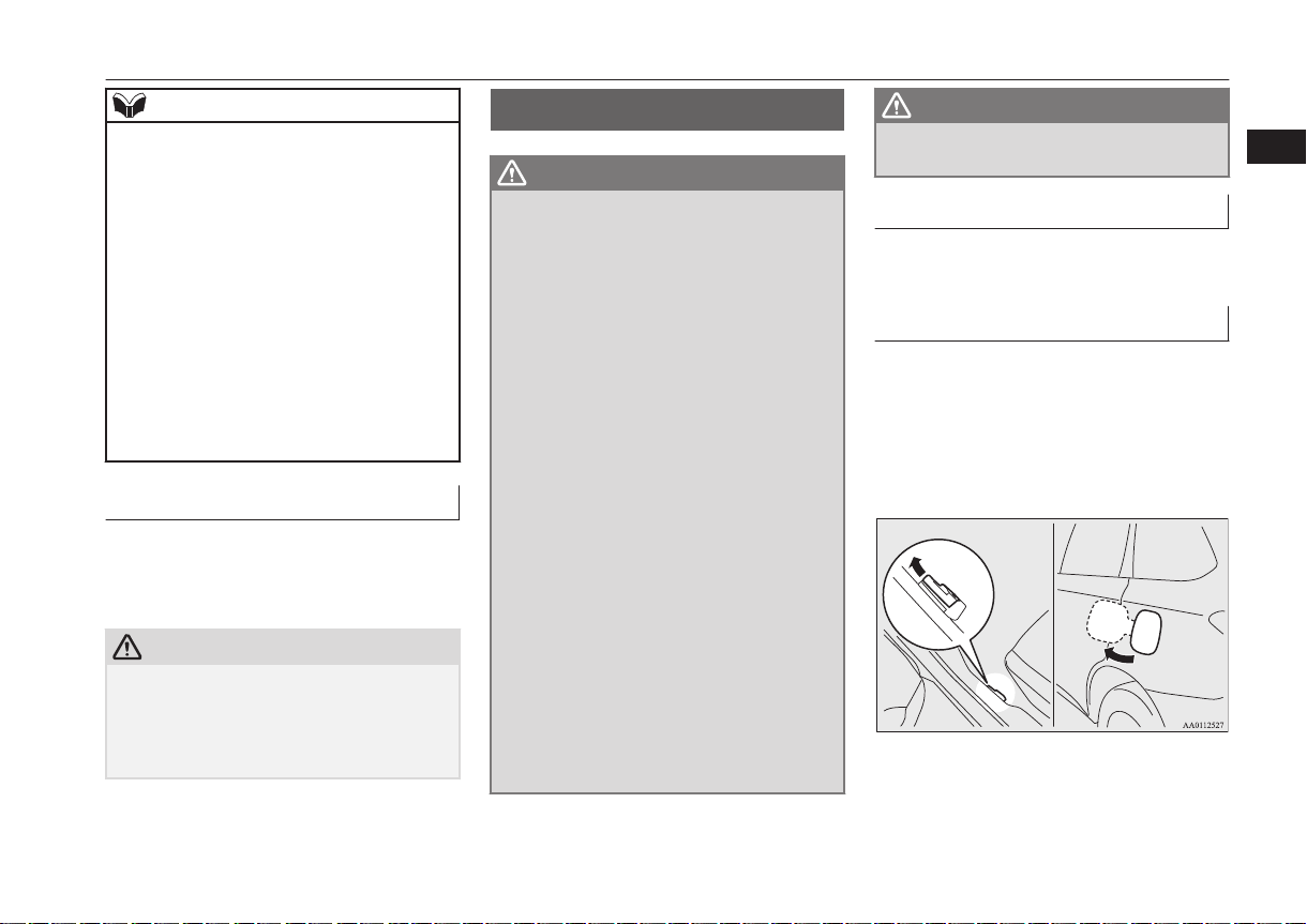
Refueling
1. Before filling with fuel, stop the engine.
2. The fuel tank filler is located on the rear
left side of your vehicle.
Open the fuel tank filler door by pulling
the release lever located on the side of
the driver’s seat.
3. Open the fuel tank filler tube by slowly
turning the cap anticlockwise.
2
OGFE17E1
General information
2-03
Installation of accessories
2
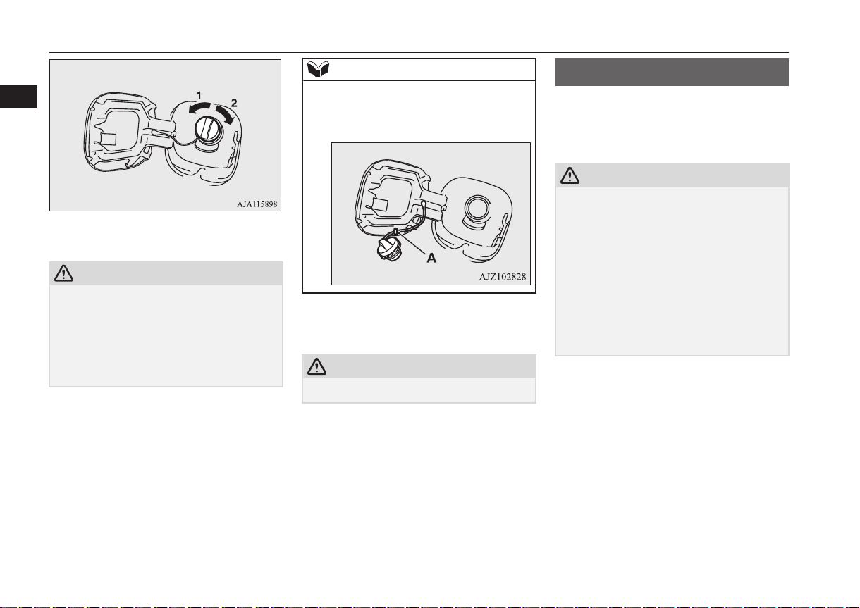
1- Remove
2- Close
CAUTION
Since the fuel system may be under pressure,
l
remove the fuel tank filler tube cap slowly.
This relieves any pressure or vacuum that
might have built up in the fuel tank. If you
hear a hissing sound, wait until it stops before removing the cap. Otherwise, fuel may
spray out, injuring you or others.
NOTE
While filling with fuel, hang the fuel cap on
l
the hook (A) located on the inside of the fuel
tank filler door.
4. Insert the gun in the tank port as far as it
goes.
CAUTION
Do not tilt the gun.
l
5. When the gun stops automatically, do
not fill with fuel any more.
6. To close, turn the fuel cap slowly clockwise until you hear clicking sounds, then
gently push the fuel tank filler door
closed.
Installation of accessories
E00200302185
We recommend you to consult your
MITSUBISHI MOTORS Authorized Service
Point.
CAUTION
Your vehicle is equipped with a diagnosis
l
connector for checking and servicing the
electronic control system.
Do not connect a device other than a diagnosis tool for inspections and service to this
connector. Otherwise, the battery could be
discharged, the electronic devices of the vehicle could malfunction, or other unexpected
problems could result.
In addition, malfunctions caused by connecting a device other than a diagnosis tool may
not be covered under warranty.
The installation of accessories, optional
l
parts, etc., should only be carried out
within the limits prescribed by law in
your country, and in accordance with the
guidelines and warnings contained within the documents accompanying this vehicle.
Installing electric components incorrect-
l
ly could lead to a fire. See to the “Modification/alteration to the electrical or fuel
systems” section within this owner’s
manual.
2-04
General information
OGFE17E1
Modification/alterations to the electrical or fuel systems
When installing the radio, for the re-
l
quired information (frequency, transmission output, installing procedure), consult a MITSUBISHI MOTORS Authorized Service Point.
If the frequency, transmission output and
installing condition are not appropriate,
it can adversely affect the electronic devices and could lead to unsafe vehicle
operation.
Using a cellular phone or radio set inside
l
the vehicle without an external antenna
may cause electrical system interference,
which could lead to unsafe vehicle operation.
Tyres and wheels which do not meet
l
specifications must not be used.
Refer to the “Specifications” section for
information regarding wheel and tyre
sizes.
Important points!
Due to large number of accessory and replacement parts of different manufactures
available in the market, it is not possible, not
only for MITSUBISHI MOTORS, but also
for a MITSUBISHI MOTORS Authorized
Service Point, to check whether the attachment or installation of such parts affects the
overall safety of your MITSUBISHI-vehicle.
Even when such parts are officially authorized, for example by a “general operators
permit” (an appraisal for the part) or through
the execution of the part in an officially approved manner of construction, or when a
single operation permit following the attachment or installation of such parts, it cannot be
deduced from that alone, that the driving
safety of your vehicle has not been affected.
Consider also that there basically exists no liability on the part of the appraiser or the official. Maximum safety can only be ensured
with parts recommended, sold and fitted or
installed by a MITSUBISHI MOTORS Authorized Service Point (MITSUBISHI
MOTORS genuine replacement parts and
MITSUBISHI MOTORS accessories). The
same also pertains to modifications of
MITSUBISHI vehicles with respect to the
production specifications. For safety reasons,
do not attempt any modifications other than
those that follow the recommendations of a
MITSUBISHI MOTORS Authorized Service
Point.
Modification/alterations to
the electrical or fuel systems
E00200400368
MITSUBISHI MOTORS CORPORATION
has always manufactured safe, high quality
vehicles. In order to maintain this safety and
quality, it is important that any accessory that
is to be fitted, or any modifications carried
out which involve the electrical or fuel systems, should be carried out in accordance
with MITSUBISHI guidelines.
CAUTION
If the wires interfere with the vehicle body
l
or improper installation methods are used
(protective fuses not included, etc.), electronic devices may be adversely affected, resulting in a fire or other accident.
Genuine parts
E00200500499
MITSUBISHI MOTORS has gone to great
lengths to bring you a superbly crafted automobile offering the highest quality and dependability.
2
OGFE17E1
General information
2-05
 Loading...