

Page 1
OUTLANDER - ENGLISH - OGXE12E1
OWNER’S MANUAL
OUTLANDER - ENGLISH - OGXE12E1
OUTLANDER
Page 2
Foreword
Thank you for selecting an OUTLANDER as your new vehicle.
This owner’s manual will add to your understanding and full enjoyment of
the many fine features of this vehicle.
It contains information prepared to acquaint you with the proper way to operate and maintain your vehicle for the utmost in driving pleasure.
MITSUBISHI MOTORS Europe B.V. reserves the right to make changes in
design and specifications and/or to make additions to or improvements in
this product without obligation to install them on products previously manufactured.
It is an absolute requirement for the driver to strictly observe all laws and regulations concerning vehicles.
This owner’s manual has been written in compliance with such laws and regulations, but some of the contents may become contradictory with later amendment of the laws and regulations.
Please leave this owner’s manual in this vehicle at time of resale. The next
owner will appreciate having access to the information contained in this owner’s manual.
Repairs to your vehicle:
Vehicles in the warranty period:
All warranty repairs must be carried out by a MITSUBISHI MOTORS Authorized Service Point.
Vehicles outside the warranty period:
Where the vehicle is repaired is at the discretion of the owner.
E09200103910
Throughout this owner’s manual the words WARNING and CAUTION ap-
pear.
These serve as reminders to be especially careful. Failure to follow instructions could result in personal injury or damage to your vehicle.
WARNING
indicates a strong possibility of severe personal injury or death if instructions are not followed.
CAUTION
means hazards or unsafe practices that could cause minor personal injury or damage to your vehicle.
You will see another important symbol:
NOTE: gives helpful information.
*: indicates optional equipment.
It may differ according to the sales classification; refer
to the sales catalogue.
Abbreviations used in this owner’s manual:
LHD: Left-Hand Drive
RHD: Right-Hand Drive
M/T: Manual Transmission
A/T: Automatic Transmission
CVT: Continuously Variable Transmission
The symbol used on the vehicles:
: See owner’s manual
Information for station service
Fuel tank capacity
Petrol-powered vehicles
Fuel
Fuel requirements
Engine oil Refer to the “Maintenance” section for the selection of engine oil.
Tyre inflation pressure Refer to the “Maintenance” section for the tyre inflation pressure.
Diesel-powered vehicles
Refer to the “General information” section for the fuel selection.
2WD models 63 litres
4WD models 60 litres
Unleaded petrol octane number (EN228)
2000 models, 2400 models, 3000 models
95 RON or higher
Cetane number (EN590)
51 or higher
CAUTION
Your vehicle is designed to use only diesel fuel that meets the EN590 standard.
l
Use of any other type of diesel fuel can adversely affect the engine.
E09300102578
© 2011 Mitsubishi Motors Corporation
OGXE12E1
BLC11.000747
12
Page 3

Table of contents
OGXE12E1
Overview
General information
Locking and unlocking 1
Seats and seat belts 2
Instruments and controls 3
Starting and driving 4
For pleasant driving 5
For emergencies 6
Vehicle care 7
Maintenance 8
Specifications 9
Page 4
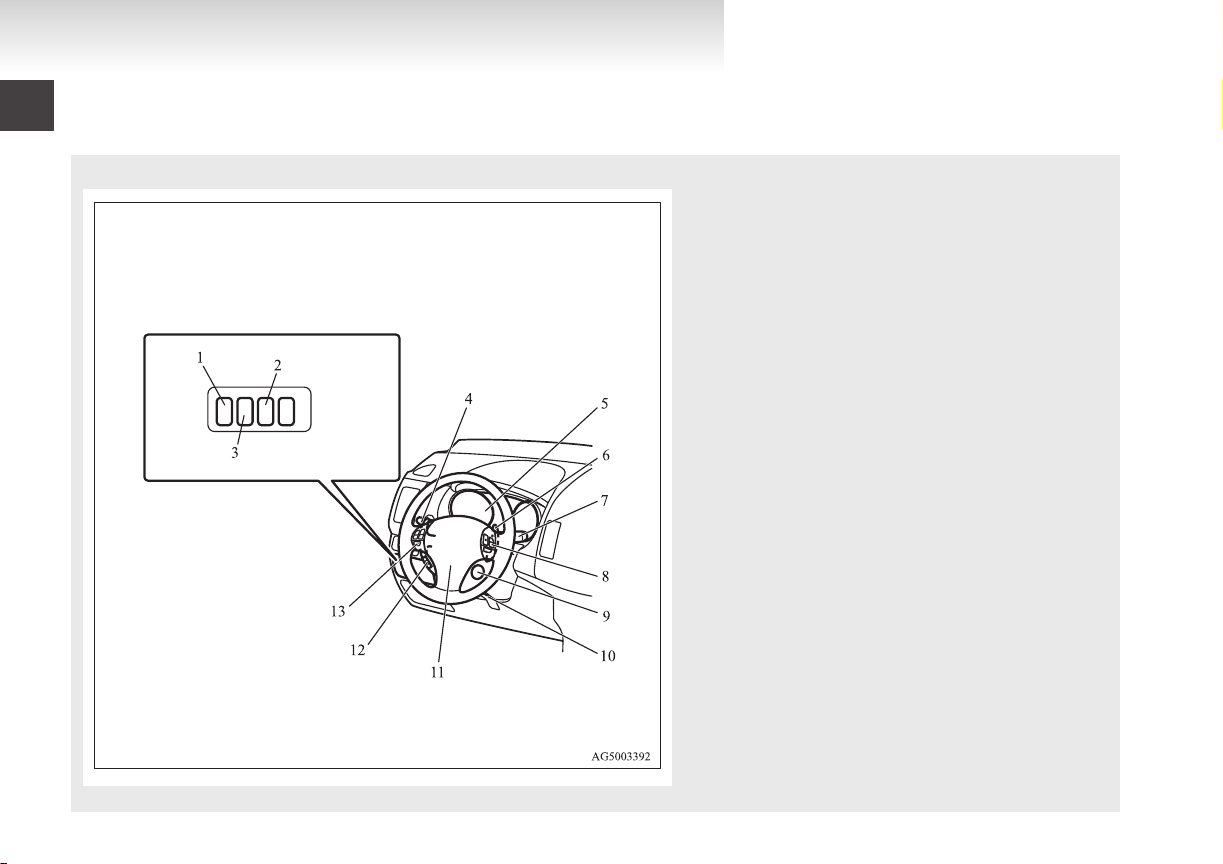
LHD
Overview
OGXE12E1
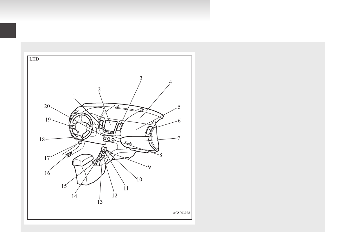
Instruments and controls
1. Headlamp levelling switch* p. 3-46
2.
3. Active stability control (ASC) OFF switch* p. 4-58
4. Combination headlamps and dipper switch p. 3-42
5. Instruments p. 3-02
6. Shift paddles* p. 4-27, 4-33, 4-42
7. Windscreen wiper and washer switch p. 3-51
8. Cruise control switch* p. 4-60
9. Ignition switch p. 1-12, 1-19, 4-13
10. Steering wheel height adjustment lever p. 4-09
11. Supplemental restraint system - airbag (for driver’s seat) p. 2-31,
12. Bluetooth® 2.0 interface* p. 5-65
13. Steering wheel audio remote control switches* p. 5-53
E00100106265
Sonar switch* p. 4-66
Auto Stop & Go (AS&G) OFF switch* p. 07, 4-22
Turn-signal lever p. 3-48
Front fog lamp switch* p. 3-50
Rear fog lamp switch p. 3-50
Headlamp washer switch* p. 3-55
Rear window wiper and washer switch p. 3-55
2-35
Horn switch p. 3-57
Page 5
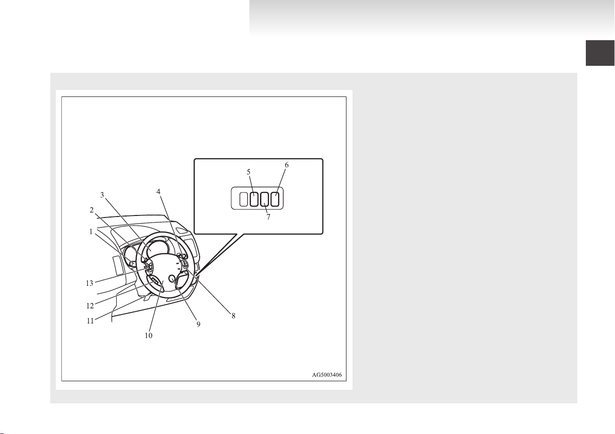
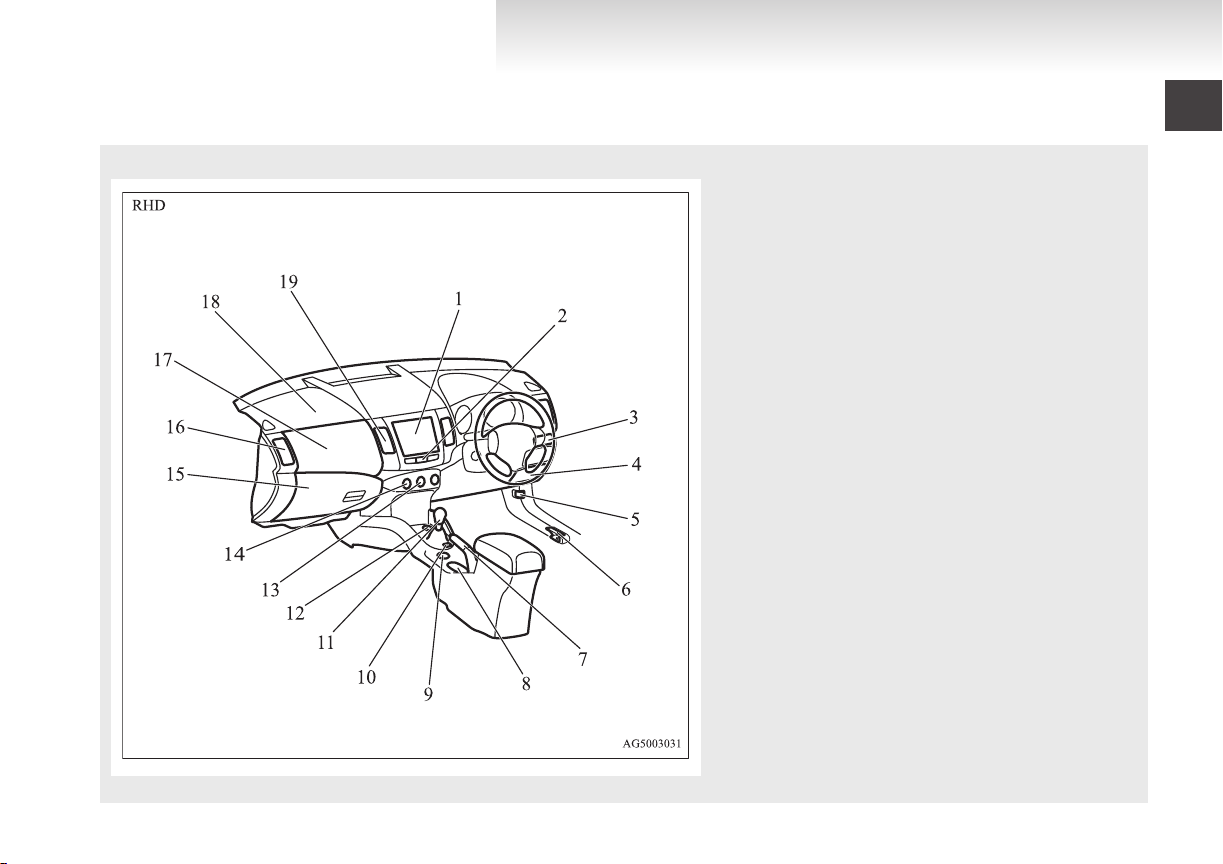
RHD
OGXE12E1
Overview
1. Combination headlamps and dipper switch p. 3-42
Turn-signal lever p. 3-48
Front fog lamp switch* p. 3-50
Rear fog lamp switch p. 3-50
Headlamp washer switch* p. 3-55
2.
Shift paddles* p. 4-27, 4-33, 4-42
3. Instruments p. 3-02
4. Windscreen wiper and washer switch p. 3-51
Rear window wiper and washer switch p. 3-55
5. Sonar switch* p. 4-66
6. Headlamp levelling switch* p. 3-46
7. Active stability control (ASC) OFF switch p. 4-58
Auto Stop & Go (AS&G) OFF switch* p. 07, 4-22
8. Cruise control switch p. 4-60
9. Ignition switch p. 1-12, 1-19, 4-13
10. Supplemental restraint system - airbag (for driver’s seat) p. 2-31,
2-35
Horn switch p. 3-57
11. Steering wheel height adjustment lever p. 4-09
12. Bluetooth® 2.0 interface* p. 5-65
13. Steering wheel audio remote control switches* p. 5-53
Page 6
Overview
OGXE12E1
1. Hazard warning flasher switch p. 3-50
2.
Digital clock* p. 5-62
Audio system* p. 5-10, 5-24
MITSUBISHI Multi-Communication System*
3. Centre ventilators p. 5-02
4. Supplemental restraint system - airbag (for front passenger’s
seat) p. 2-31, 2-35
5. Upper glove box p. 5-88
6. Side ventilators p. 5-02
7. Lower glove box p. 5-88
Front passenger’s airbag ON-OFF switch p. 2-33
8. Rear window demister switch p. 3-56
Wiper de-icer switch* p. 3-56
9. Accessory socket* p. 5-84
Cigarette lighter* p. 5-83
10. Ashtray* p. 5-83
11. Gearshift or selector lever p. 4-23, 4-25, 4-30, 4-36
12. Parking brake lever p. 4-07
13. Twin Clutch SST control mode switch* p. 4-40
14. Drive mode selector* p. 4-46
15. Cup holder p. 5-91
16. Fuel tank filler door release lever p. 03
17. Bonnet release lever p. 8-03
18. Personal box p. 5-90
Fuse box p. 8-18
19. Built-in cup holder p. 5-91
20. Air conditioning p. 5-04
Page 7
Overview
OGXE12E1
1. Digital clock* p. 5-62
Audio system* p. 5-10, 5-24
MITSUBISHI Multi-Communication System*
2.
Hazard warning flasher switch p. 3-50
3. Built-in cup holder p. 5-91
4. Personal box p. 5-90
5. Bonnet release lever p. 8-03
6. Fuel tank filler door release lever p. 03
7. Parking brake lever p. 4-07
8. Cup holder p. 5-91
9. Drive mode selector* p. 4-46
10. Twin Clutch SST control mode switch* p. 4-40
11. Gearshift lever p. 4-22, 4-25, 4-30, 4-36
12. Accessory socket* p. 5-84
13. Air conditioning p. 5-04
14. Rear window demister switch p. 3-56
15. Lower glove box p. 5-88
Front passenger’s airbag ON-OFF switch p. 2-33
Fuse box p. 8-18
16. Side ventilators p. 5-02
17. Upper glove box p. 5-88
18. Supplemental restraint system - airbag (for front passenger’s
seat) p. 2-31, 2-35
19. Centre ventilators p. 5-02
Page 8
Overview
OGXE12E1
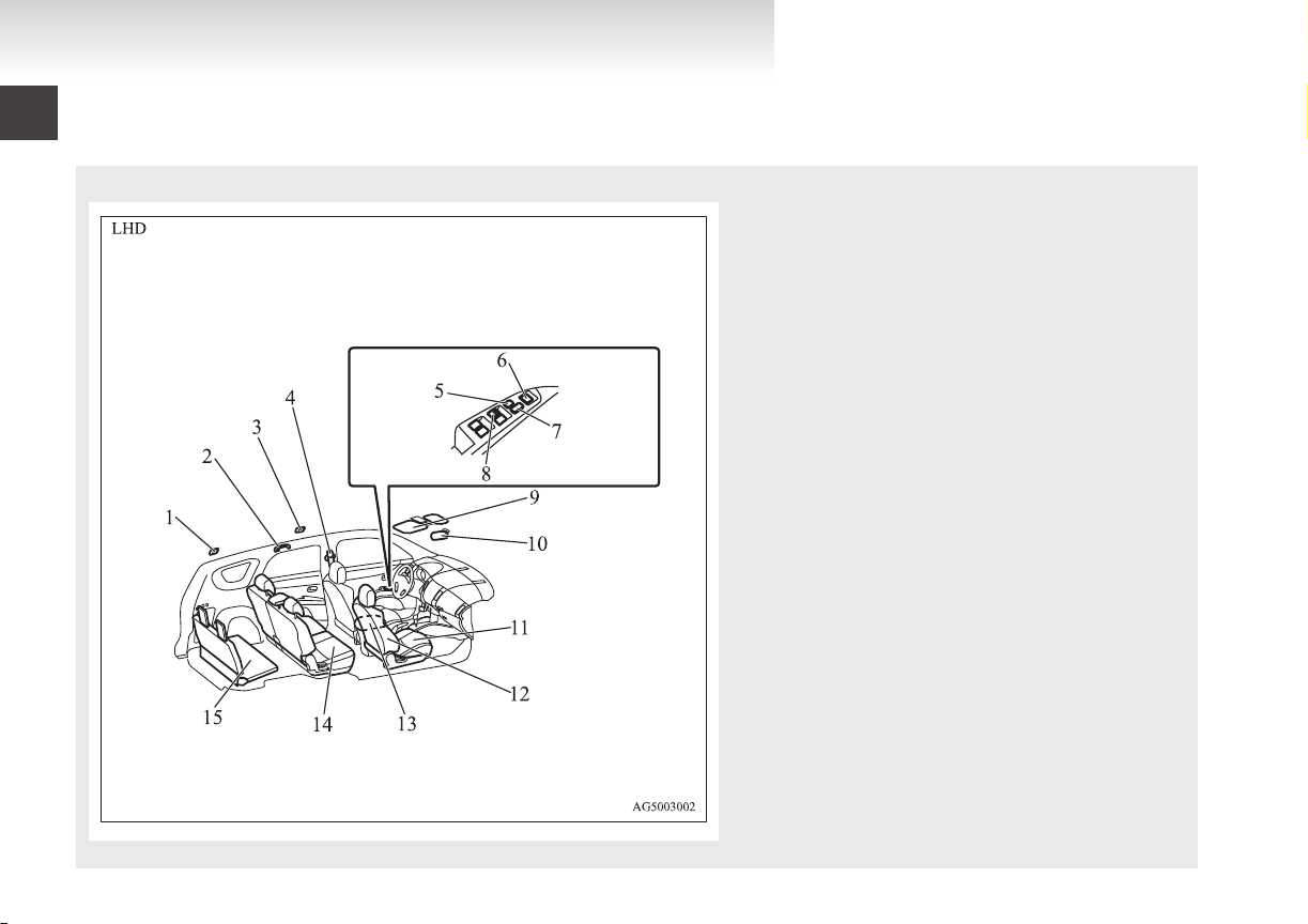
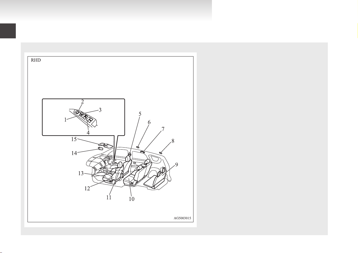
Interior
1. Luggage room lamp p. 5-87
2.
Assist grip p. 5-94
Coat hook p. 5-94
3. Room lamp (rear) p. 5-85
4. Adjustable seat belt anchor p. 2-21
Seat belts p. 2-19
5. Lock switch p. 1-41
6. Electric remote-controlled outside rear-view mirrors
switch p. 4-11
7. Central door lock switch p. 1-28
8. Electric window control switch p. 1-41
9. Sun visors p. 5-82
Vanity mirror p. 5-82
Card holder p. 5-82
10. Inside rear-view mirror p. 4-09, 4-70
11. Front seat p. 2-05
12. Supplemental restraint system - side airbag (for front
seat)* p. 2-31
13. Armrest p. 2-07
Accessory socket* p. 5-84
14. Second seat p. 2-08
15. Underfloor-stowable third seat (7 persons) p. 2-10
E00100204435
Page 9
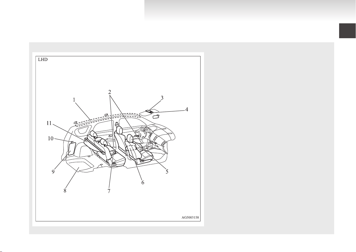
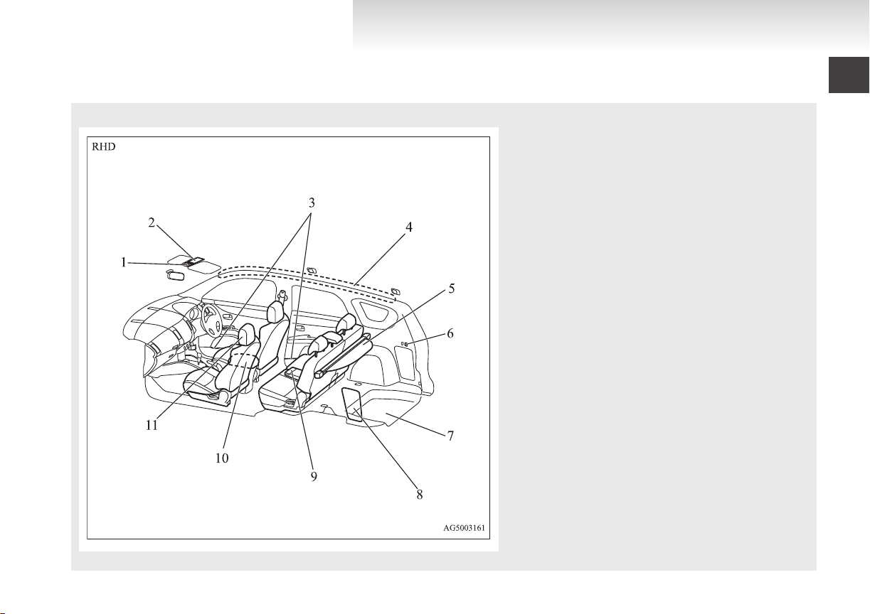
1. Supplemental restraint system - curtain airbag* p. 2-31, 2-38
OGXE12E1
2.
Bottle holder p. 5-92
3. Sunglasses holder* p. 5-90
4. Sunroof switch* p. 1-43
Map lamp & room lamp (front) p. 5-85, 5-86
5. Head restraints p. 2-14
6. Auxiliary Audio connector (RCA)* p. 5-52
Auxiliary Video connector (RCA)* p. 5-52
USB input terminal* p. 5-80
7. Armrest p. 2-09
Cup holder p. 5-91
8. Luggage floor box (5 persons)* p. 5-91
9. Quarter trim box* p. 5-91
10. Luggage area switch* p. 2-15
11. Cargo area cover* p. 5-93
Overview
Page 10
Overview
OGXE12E1
1. Lock switch p. 1-41
2.
Electric remote-controlled outside rear-view mirrors
switch p. 4-11
3. Central door lock switch p. 1-28
4. Electric window control switch p. 1-41
5. Adjustable seat belt anchor p. 2-21
Seat belts p. 2-19
6. Room lamp (rear) p. 5-85
7. Assist grip p. 5-94
Coat hook p. 5-94
8. Luggage room lamp p. 5-87
9. Underfloor-stowable third seat (7 persons) p. 2-10
10. Second seat p. 2-08
11. Armrest p. 2-07
Accessory socket* p. 5-84
12. Supplemental restraint system - side airbag (for front seat)*
p. 2-37
13. Front seat p. 2-05
14. Inside rear-view mirror p. 4-09, 4-70
15. Sun visors p. 5-82
Card holder p. 5-82
Vanity mirror p. 5-82
Page 11
1. Sunroof switch* p. 1-43
OGXE12E1
Map lamp & room lamp (front)
p. 5-85, 5-86
2. Sunglasses holder* p. 5-90
3. Bottle holder p. 5-92
4. Supplemental restraint system - curtain airbag p. 2-31, 2-38
5. Cargo area cover* p. 5-93
6. Luggage area switch* p. 2-15
7. Luggage floor box (5 persons) p. 5-91
8. Quarter trim box* p. 5-91
9. Armrest p. 2-09
Cup holder p. 5-91
10. Auxiliary Audio connector (RCA)* p. 5-52
Auxiliary Video connector (RCA)* p. 5-52
USB input terminal* p. 5-80
11. Head restraints p. 2-14
Overview
Page 12
1
2
3
4
5
6
Overview
OGXE12E1
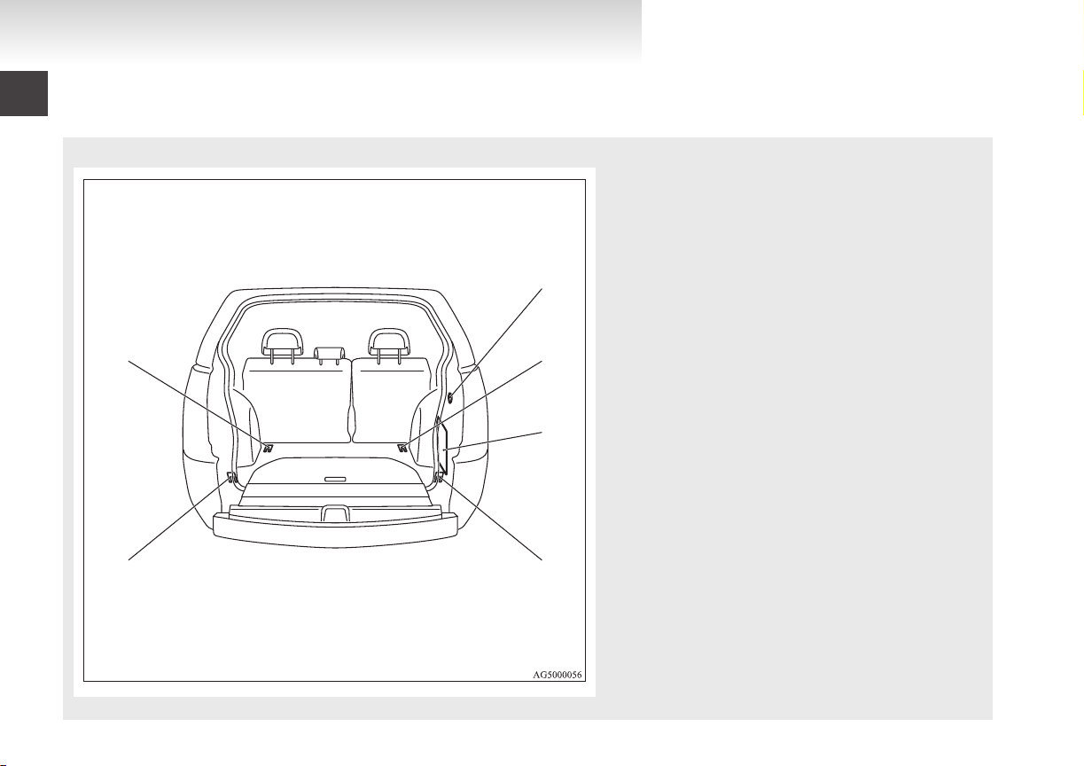
Luggage area
1. Luggage hook p. 5-94
2.
Accessory socket* p. 5-84
3. Luggage hook p. 5-94
4. Jack p. 6-08
Tools p. 6-08
5. Luggage hook p. 5-94
6. Luggage hook p. 5-94
E00100401478
Page 13
Except for high intensity discharge headlamp type High intensity discharge headlamps type
Except for high intensity discharge headlamp type
1
2
3
4
5
6
7
8
9
10
11
12
13
14
15
16
High intensity discharge headlamps type
Overview
OGXE12E1
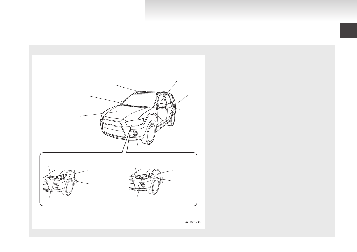
Outside (Front)
E00100504568
1. Bonnet p. 8-03
2.
Windscreen wipers p. 3-51
3. Sunroof* p. 1-43
4. Electric window control p. 1-41
5. Fuel tank filler p. 03
6. Outside rear-view mirror p. 4-11
Side turn-signal lamps* p. 3-48, 8-24, 8-29
7. Side turn-signal lamps* p. 3-48, 8-24, 8-29
8. Front fog lamps* p. 3-50, 8-24, 8-29
9. Front turn-signal lamps p. 3-48, 8-24, 8-29
10. Headlamps, high/low beam p. 3-42, 8-24, 8-27
11. Position lamps p. 3-42, 8-24, 8-28
12. Bending lamp (Adaptive Front light System (AFS)) p. 3-48, 8-24,
8-27
13. Front turn-signal lamps p. 3-48, 8-24, 8-29
14. Headlamps, low beam p. 3-42, 8-24, 8-25
15. Position lamps p. 3-42, 8-24, 8-28
16. Headlamps, high-beam p. 3-42, 8-24, 8-26
Page 14
1
2
3
4
5
6
7
8
9
10
11
12
13
14
15
Overview
OGXE12E1
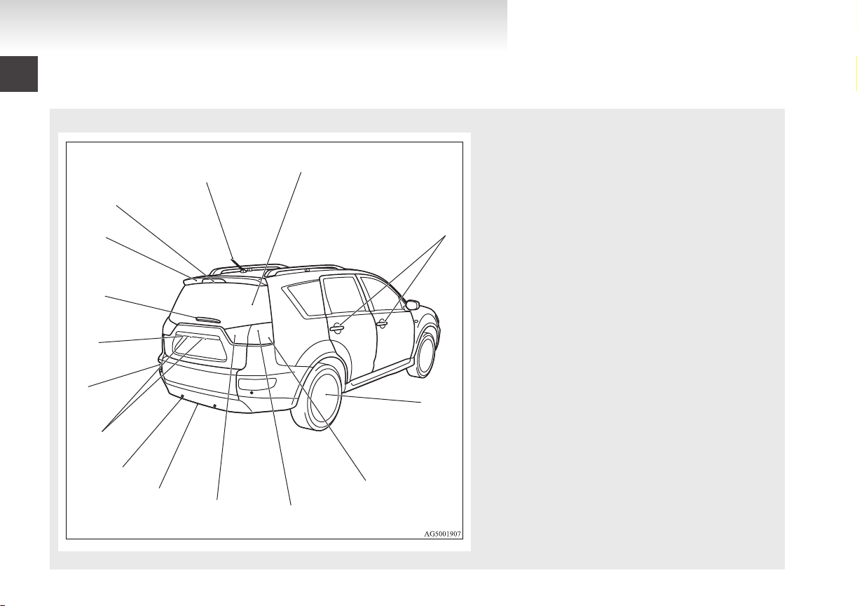
Outside (Rear)
1. Split tailgate p. 1-31
2.
Keyless entry system* p. 1-04
Keyless operation system* p. 1-07
Locking and unlocking the doors p. 1-26
3. Size of tyres and wheels p. 9-16
Tyre inflation pressures p. 8-12
Changing tyres p. 6-09
Tyre rotation p. 8-13
Tyre chains p. 8-14
4. Turn-signal lamps p. 3-48, 8-24, 8-32
5. Stop lamps/Tail lamps p. 3-42, 8-24, 8-32
6. Reversing lamps p. 3-42, 8-24, 8-32
7. Spare wheel p. 6-10
8. Back sensor* p. 4-65
9. Licence plate lamps p. 3-42, 8-24, 8-33
10. Rear fog lamp p. 3-42, 8-24, 8-31
11. Rear-view camera* p. 4-68
12. Rear window wiper p. 3-55
13. Rear spoiler
14. High-mounted stop lamp p. 8-24, 8-33
15. Antenna p. 5-61
E00100504571
Page 15

General information
OGXE12E1
Fuel selection...................................................................................02
Filling the fuel tank..........................................................................03
Installation of accessories................................................................04
Modification/alterations to the electrical or fuel systems................05
Genuine parts...................................................................................05
Safety and disposal information for used engine oil........................06
Disposal information for used batteries...........................................06
Auto Stop & Go (AS&G) system*..................................................06
Page 16
General information
OGXE12E1
Fuel selection
Petrol-powered vehicles
Unleaded
ber (EN228)
Recommended
fuel
Diesel-powered vehicles
Cetane number (EN590)
petrol octane num-
2000 models, 2400 models, 3000 models
95 RON or higher
51 or higher
CAUTION
For
petrol-powered vehicles, the use of lea-
l
ded fuel can result in serious damage to
the engine and catalytic converter. Do not
use leaded fuel.
Diesel-powered vehicles are designed to
l
use only diesel fuel that meets the EN590
standard.
Use of any other type of diesel fuel (bio
diesel, methylester, etc.) would adversely
affect the engine’s performance and durability.
E00200102763
NOTE
Petrol-powered
l
trol system so that you can use unleaded petrol 90 RON as an emergent measure in case
unleaded petrol 95 RON or higher is not available on journey, etc.
In such a case, you don’t need to adjust the
engine specially. In case of using unleaded
petrol 90 RON, the engine performance level
is reduced.
Due to the separation of paraffin, the fluidity
l
of the fuel decreases considerably as the temperature falls.
Because of this fact there are two kinds of
fuel: “summer” and “winter”.
This must be considered in winter use.
Select either of the two kinds of fuel in accordance with ambient temperature.
Above -5 °C: “Summer” diesel
Below -5 °C: “Winter” diesel
When travelling abroad, find out in advance
about the fuels served in local service stations.
Repeatedly driving short distances at low
l
speeds can cause deposits to form in the fuel
system and engine, resulting in poor starting
and poor acceleration. If these problems occur, you are advised to add a detergent additive to the gasoline when you refuel the vehicle. The additive will remove the deposits,
thereby returning the engine to a normal condition. Be sure to use a genuine
MITSUBISHI FUEL SYSTEM CLEANER.
Using an unsuitable additive could make the
engine malfunction. For details, please contact a MITSUBISHI MOTORS Authorized
Service Point.
vehicles have the knock con-
quality petrol can cause problems such
Poor
l
as difficult starting, stalling, engine noise
and hesitation. If you experience these problems, try another brand and/or grade of petrol.
If the check engine warning lamp flashes,
have the system checked as soon as possible
at a MITSUBISHI MOTORS Authorized
Service Point.
E10 type petrol
The petrol engines are compatible with E10
petrol (containing 10 % ethanol) conforming to European standards EN 228.
E00203200022
type
CAUTION
Do not use more than
l
of ethanol (grain alcohol) by volume.
Use of more than 10 % concentration
may lead to damage to your vehicle fuel
system, engine, engine sensors and exhaust system.
10 % concentration
02
Page 17
Filling the fuel tank
Except for vehicles equipped with Twin Clutch SST
For vehicles equipped with Twin Clutch SST
OGXE12E1
WARNING
handling fuel, comply with the safe-
When
l
ty regulations displayed by garages and
filling stations.
Before removing the fuel cap, be sure to
l
get rid of your body’s static electricity by
touching a metal part of the car or the
fuel pump. Any static electricity on your
body could create a spark that ignites
fuel vapour.
Perform the whole refueling process
l
(opening the fuel tank filler door, removing the fuel cap, etc.) by yourself. Do not
let any other person come near the fuel
tank filler. If you allowed a person to
help you and that person was carrying
static electricity, fuel vapour could be ignited.
Do not move away from the fuel tank fill-
l
er until refueling is finished. If you
moved away and did something else (for
example, cleaning your windscreen) partway through the refueling process, you
could pick up a fresh charge of static electricity.
If the tank cap must be replaced, use only
l
a MITSUBISHI MOTORS original part.
Fuel tank capacity
2WD: 63 litres
4WD: 60 litres
E00200202429
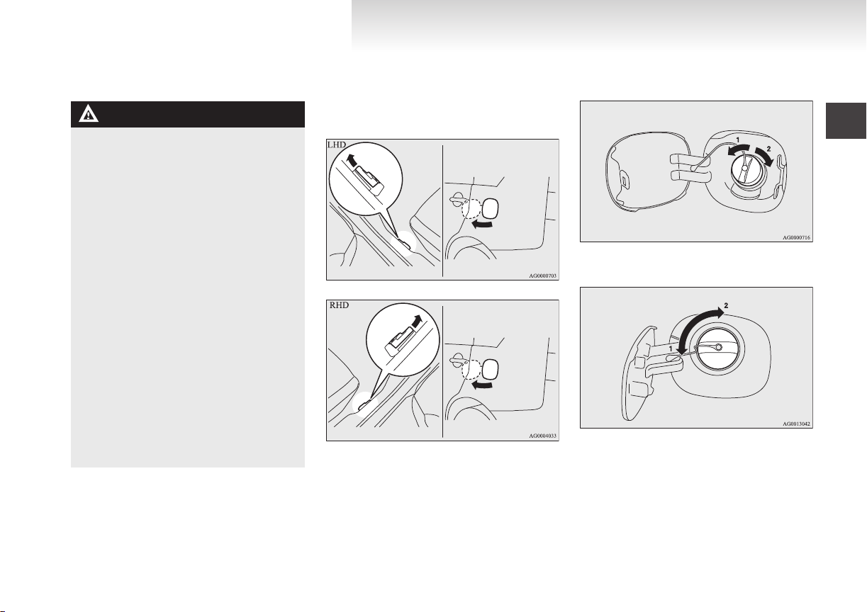
fuel tank filler is located on the rear left
2. The
side of your vehicle.
Open the fuel tank filler door by pulling the
release lever located on the side of the driver’s seat.
3. Remove the fuel cap.
General information
Open the fuel tank filler tube by slowly turning the cap anticlockwise.
1- Remove
2-
Close
1- Remove
Close
2-
Refueling
1.
Before filling with fuel, stop the engine.
03
Page 18

General information
OGXE12E1
CAUTION
For vehicles with Twin Clutch SST, the
l
fuel cap does not turn more than 90 degrees.
Turning forcibly could damage the fuel
cap.
Since the fuel system may be under pres-
l
sure, remove the fuel cap slowly. This relieves any pressure or vacuum that might
have built up in the fuel tank. If you hear
a hissing sound from the cap, wait until it
stops before removing the cap. Otherwise, fuel may spray out, injuring you or
others.
NOTE
Except
l
l
4. Insert the gun in the tank port as far as it goes.
for vehicles with Twin Clutch SST,
while filling with fuel, store the cap in the
cap holder located on the inside of the fuel
tank filler door.
For vehicles with Twin Clutch SST, while filling with fuel, hang the fuel cap on the hook
located on the inside of the fuel tank filler
door.
CAUTION
Do not tilt the gun.
l
6. Close the fuel cap.
[Except for vehicles with Twin Clutch SST]
close, turn the fuel cap slowly clockwise
To
until you hear clicking sounds, then gently
push the fuel tank filler door closed.
[For vehicles with Twin Clutch SST]
Fit the fuel cap with the cap handle sideways
and turn it clockwise.
Installation of accessories
recommend you to consult your MITSUBISHI
We
MOTORS Authorized Service Point.
The installation of accessories, optional com-
l
ponents, etc., should only be carried out within the limits prescribed by law in your country, and in accordance with the guidelines
and warnings contained within the documents accompanying this vehicle.
Installing electric components incorrectly
l
could lead to a fire. See to the “Modification/
alteration to the electrical or fuel systems”
section within this owner’s manual.
Using a cellular phone or radio set inside the
l
vehicle without an external antenna may
cause electrical system interference, which
could lead to unsafe vehicle operation.
Tyres and wheels which do not meet specifi-
l
cations must not be used.
Refer to the “Specifications” section for information regarding wheel and tyre sizes.
E00200300963
Important points!
Due to large number of accessory and replacement
parts of different manufactures available in the market, it is not possible, not only for MITSUBISHI
MOTORS, but also for a MITSUBISHI MOTORS
Authorized Service Point, to check whether the attachment or installation of such parts affects the
overall safety of your MITSUBISHI-vehicle.
5. When
with fuel any more.
04
the gun stops automatically, do not fill
Page 19
Even when such parts are officially authorized, for
OGXE12E1
example by a “general operators permit” (an appraisal for the part) or through the execution of the
part in an officially approved manner of construction, or when a single operation permit following
the attachment or installation of such parts, it cannot be deduced from that alone, that the driving safety of your vehicle has not been affected.
Consider also that there basically exists no liability
on the part of the appraiser or the official. Maximum safety can only be ensured with parts recommended, sold and fitted or installed by a
MITSUBISHI MOTORS Authorized Service Point
(MITSUBISHI MOTORS genuine replacement
parts and MITSUBISHI MOTORS accessories).
The same also pertains to modifications of
MITSUBISHI vehicles with respect to the production specifications. For safety reasons, do not attempt any modifications other than those that follow the recommendations of a MITSUBISHI
MOTORS Authorized Service Point.
Modification/alterations to the
electrical or fuel systems
MITSUBISHI MOTORS
ways manufactured safe, high quality vehicles. In
order to maintain this safety and quality, it is important that any accessory that is to be fitted, or any
modifications carried out which involve the electrical or fuel systems, should be carried out in accordance with MITSUBISHI guidelines.
CORPORATION has al-
E00200400368
CAUTION
the wires interfere with the vehicle
If
l
body or improper installation methods
are used (protective fuses not included,
etc.), electronic devices may be adversely
affected, resulting in a fire or other accident.
General information
Genuine parts
MITSUBISHI MOTORS has gone to great lengths
to bring you a superbly crafted automobile offering
the highest quality and dependability.
Use MITSUBISHI MOTORS Genuine Parts, designed and manufactured to maintain your
MITSUBISHI MOTORS automobile at top performance. MITSUBISHI MOTORS Genuine Parts
are identified by this mark and are available at all
MITSUBISHI MOTORS Authorized Service
Points.
E00200500499
05
Page 20
General information
OGXE12E1
Safety and disposal information
for used engine oil
E00200600155
WARNING
Prolonged
l
cause serious skin disorders, including
dermatitis and cancer.
Avoid contact with the skin as far as pos-
l
sible and wash thoroughly after any contact.
Keep used engine oils out of reach of chil-
l
dren.
Protect the environment
It
is illegal to pollute drains, water courses and soil.
Use authorized waste collection facilities, including civic amenity sites and garages providing facilities for disposal of used oil and used oil filters. If in
doubt, contact your local authority for advice on disposal.
and repeated contact may
Disposal information for used
batteries
Your vehicle contains batteries
and/or accumulators.
Do
not mix with general household waste.
For proper treatment, recovery
and recycling of used batteries,
please take them to applicable collection points, in accordance
with your national legislation
and the Directives 2006/66/EC.
By disposing of these batteries
correctly, you will help to save
valuable resources and prevent
any potential negative effects on
human health and the environment which could otherwise
arise from inappropriate waste
handling.
E00201300032
Auto Stop & Go (AS&G) system*
This paragraph summarizes the major items of the
Auto
Stop & Go (AS&G) system such as the characteristics, operating procedures, etc. For details,
refer to “Auto Stop & Go (AS&G) system” on
page 4-19.
The Auto Stop & Go (AS&G) system reduces the
emission of exhaust gases and increases fuel efficiency.
The Auto Stop & Go (AS&G) system automatically stops and restarts the engine without the use of
the ignition switch when the vehicle is stopped,
such as at traffic lights or in a traffic jam.
Activation
The Auto Stop & Go (AS&G) system is automatically activated when the ignition switch is turned to
the “ON” position.
E00201500034
E00201600035
06
Page 21
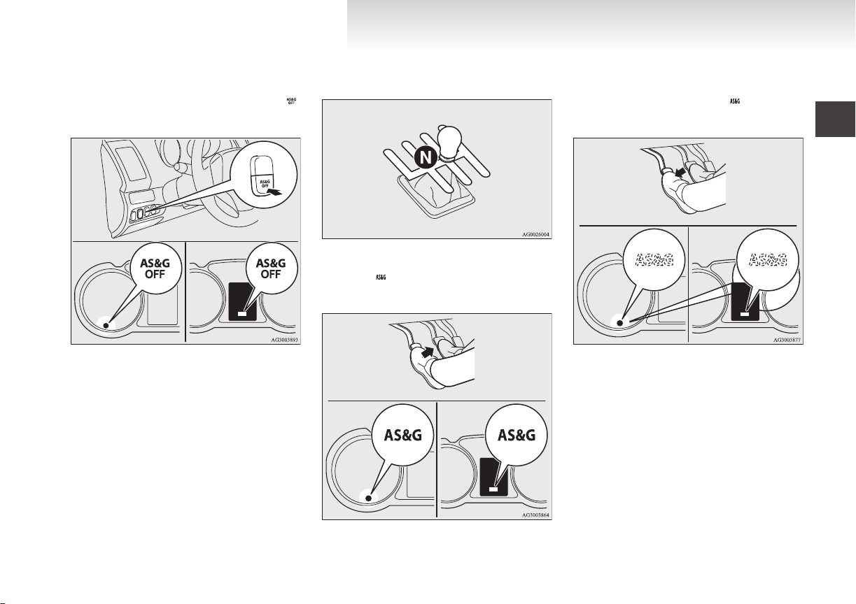
Deactivation
Type 2Type 1
Type 1 Type 2
Type 2Type 1
OGXE12E1
can deactivate the system by pressing the “Au-
You
E00201700052
to Stop & Go (AS&G) OFF” switch. Then the “
display/indicator will turn on.
2. Place the gearshift lever in the “N” (Neutral)
position.
”
3. Release the clutch pedal.
4.
The “”
display/indicator will turn on and
the engine will stop automatically.
General information
Auto go
E00201900054
Depress the clutch pedal while the gearshift lever is
the “N” (Neutral) position. The “
in
” display/indi-
cator turns off and the engine restarts automatically.
Auto stop
1. Stop the vehicle.
E00201800053
System characteristics
E00202300039
The principle of the Auto Stop & Go (AS&G) system
is that it adapts to the vehicle’s needs (i.e. energy supply). This means that in certain circumstances the engine will not stop and in other circumstances the engine will restart by itself.
Circumstances when the engine will restart by itself
The interior temperature rises and the air con-
l
ditioning starts operating in order to lower
E00202400030
the temperature.
Electric power consumption is high.
l
The brake pedal is depressed repeatedly.
l
07
Page 22
General information
OGXE12E1
speed is 3 km/h (2 mph) or higher
Vehicle
l
when coasting on a slope.
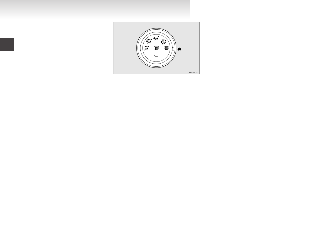
Mode selection dial is set to the demister po-
l
sition.
When the air conditioning is operated by
l
pressing the air conditioning switch.
When the preset temperature of the air condi-
l
tioning is changed significantly.
When the air conditioning is operated in AU-
l
TO mode where the temperature control dial
is set to the max. hot or the max. cool position (for vehicles with automatic air conditioning).
Other than the conditions mentioned above, the engine may restart automatically. For details, refer to
“Auto Stop & Go (AS&G) system” on page 4-19.
Circumstances when the engine will not stop
Ambient
l
mately 3 °C.
After the engine restarts automatically and
l
the vehicle stops again within 10 seconds.
After the engine restarts automatically and
l
the vehicle remains stationary.
Mode selection dial is set to the demister po-
l
sition (see illustration below).
temperature is lower than approxi-
E00202500031
the air conditioning is operated in AU-
When
l
TO mode where the temperature control dial
is set to the max. hot or the max. cool position (for vehicles with automatic air conditioning).
Other than the conditions mentioned above, the engine may not stop automatically. For details, refer
to “Auto Stop & Go (AS&G) system” on page 4-19.
08
Page 23

Locking and unlocking
OGXE12E1
Keys..............................................................................................1-02
Electronic immobilizer (Anti-theft starting system).....................1-03
Keyless entry system*..................................................................1-04
Keyless operation system*...........................................................1-07
Doors............................................................................................1-26
Central door locks.........................................................................1-28
Dead Lock System*......................................................................1-29
“Child-protection” rear doors.......................................................1-31
Split tailgate..................................................................................1-31
Inside tailgate release
Security alarm system*.................................................................1-35
Electric window control................................................................1-41
Sunroof*.......................................................................................1-43
....................................................................1-34
1
Page 24
Locking and unlocking
OGXE12E1
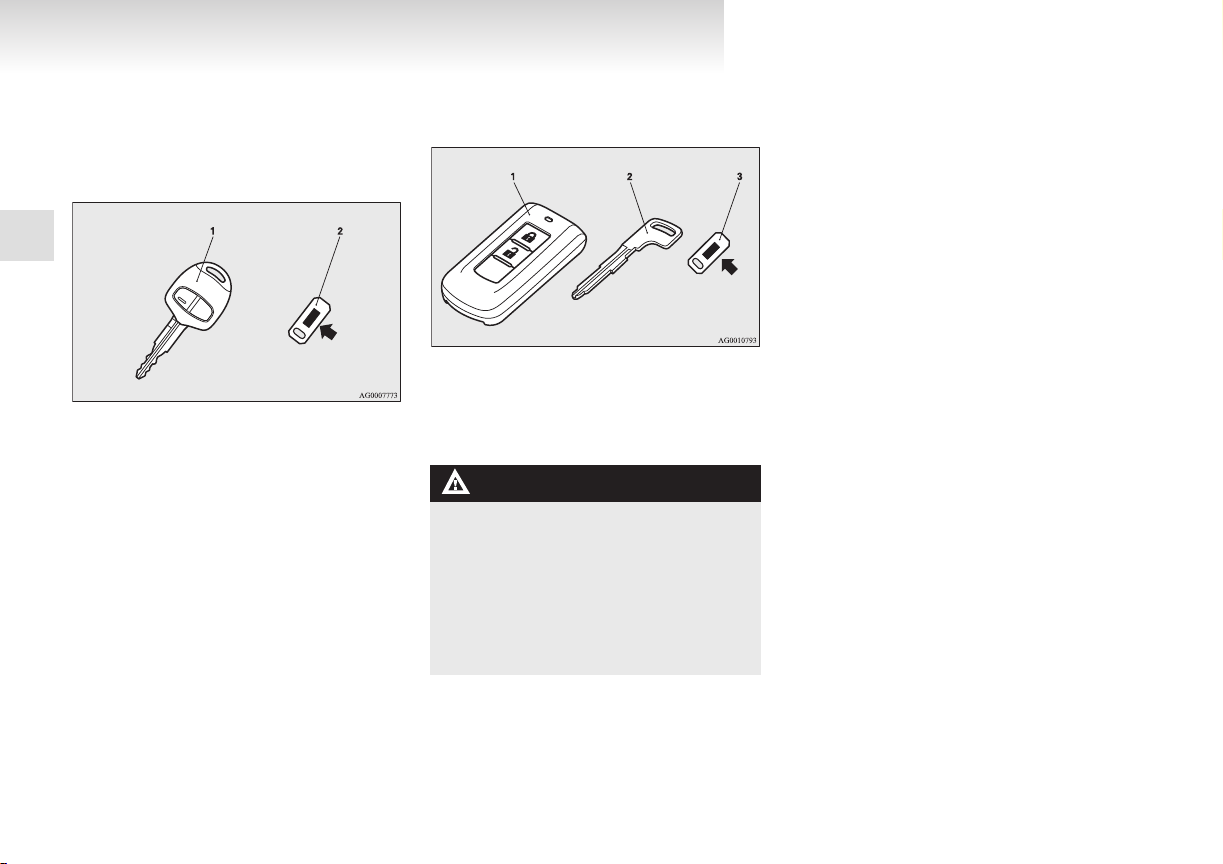
Type 1
The key fits all locks.
1
1- Keyless entry key
2-
Keys
(with electronic immobilizer)
Key number tag
E00300102373
Type 2
The emergency key fits all locks.
1- Keyless operation key
(with
electronic immobilizer and keyless en-
try system function)
2- Emergency key
3- Key number tag
WARNING
When taking a key on flights, do not
l
press any switches on the key while on
the plane. If a switch is pressed on the
plane, the key emits electromagnetic
waves, which could adversely affect the
plane’s flight operation.
When carrying a key in a bag, be careful
that no switches on the key can be easily
pressed by mistake.
NOTE
The
key number is stamped on the tag as in-
l
dicated in the illustration.
Make a record of the key number and store
the key and key number tag in separate places, so that you can order a key in the event
the original keys are lost.
The key is a precision electronic device with
l
a built-in signal transmitter. Please observe
the following in order to prevent a malfunction.
• Do not leave in a place that is exposed to
direct sunlight, for example on the dashboard.
• Do not disassemble or modify.
• Do not excessively bend the key or subject it to strong impacts.
• Do not expose to water.
• Keep away from magnetic key rings.
• Keep away from audio systems, personal
computers, TVs, and other equipment
that generates a magnetic field.
• Keep away from devices that emit strong
electromagnetic waves, such as cellular
phones, wireless devices and high frequency equipment (including medical devices).
• Do not clean with ultrasonic cleaners or
similar equipment.
• Do not leave the key where it may be exposed to high temperature or high humidity.
The engine is designed so that it will not
l
start if the ID code registered in the immobilizer computer and the key’s ID code do not
match. Refer to the “Electronic immobilizer”
section for details and key usage.
[For vehicles equipped with the security
l
alarm system]
1-02
Page 25
Pay attention to the following if the security
OGXE12E1
alarm is set to “Active”.
Refer to “Security alarm system” on page
1-35.
• If the security alarm is in the system
armed mode, the alarm will sound if the
doors are opened after being unlocked
with the key, the inside lock knob or the
central door lock switch.
• Even if the security alarm is set to “Active”, the system preparation mode is not
entered if the keyless entry system or the
keyless operation function was not used
to lock the vehicle.
Electronic immobilizer (Anti-
theft starting system)
vehicles equipped with keyless operation sys-
[For
tem]
For information on operations for vehicles equipped with the keyless operation system, refer to
“Keyless operation system: Electronic immobilizer
(Anti-theft starting system)” on page 1-11.
[Except for vehicles equipped with keyless operation system]
The electronic immobilizer is designed to significantly reduce the possibility of vehicle theft. The
purpose of the system is to immobilize the vehicle
if an invalid start is attempted. A valid start attempt
can only be achieved by using a key “registered” to
the immobilizer system.
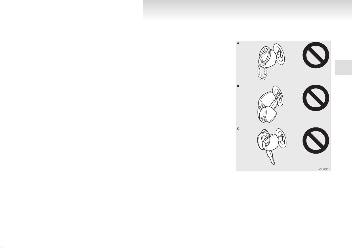
NOTE
In the following cases, the vehicle may not
l
be able to receive the registered ID code
from the registered key and the engine may
not start.
• When the key contacts a key ring or other
metallic or magnetic object (Type A)
• When the key grip contacts metal of another key (Type B)
• When the key contacts or is close to other
immobilizing keys (including keys of other vehicles) (Type C)
In cases like these, remove the object or
additional key from the vehicle key. Then
try again to start the engine. If the engine
does not start, we recommend you to con-
E00300201902
Locking and unlocking
tact your MITSUBISHI MOTORS
thorized Service Point.
you lose one of them, contact a
If
l
MITSUBISHI MOTORS Authorized Service
Point as soon as possible. To obtain a replacement or extra spare key, take your vehicle
and all remaining keys to your MITSUBISHI
MOTORS Authorized Service Point. All the
keys have to be re-registered in the immobilizer computer unit. The immobilizer can register up to 8 different keys.
Au-
1
1-03
Page 26
Locking and unlocking
OGXE12E1
1
CAUTION
Do not modify or add parts to the immo-
l
bilizer system. Doing so could cause the
immobilizer to malfunction.
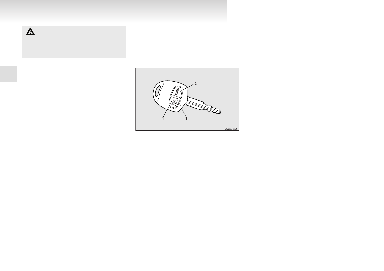
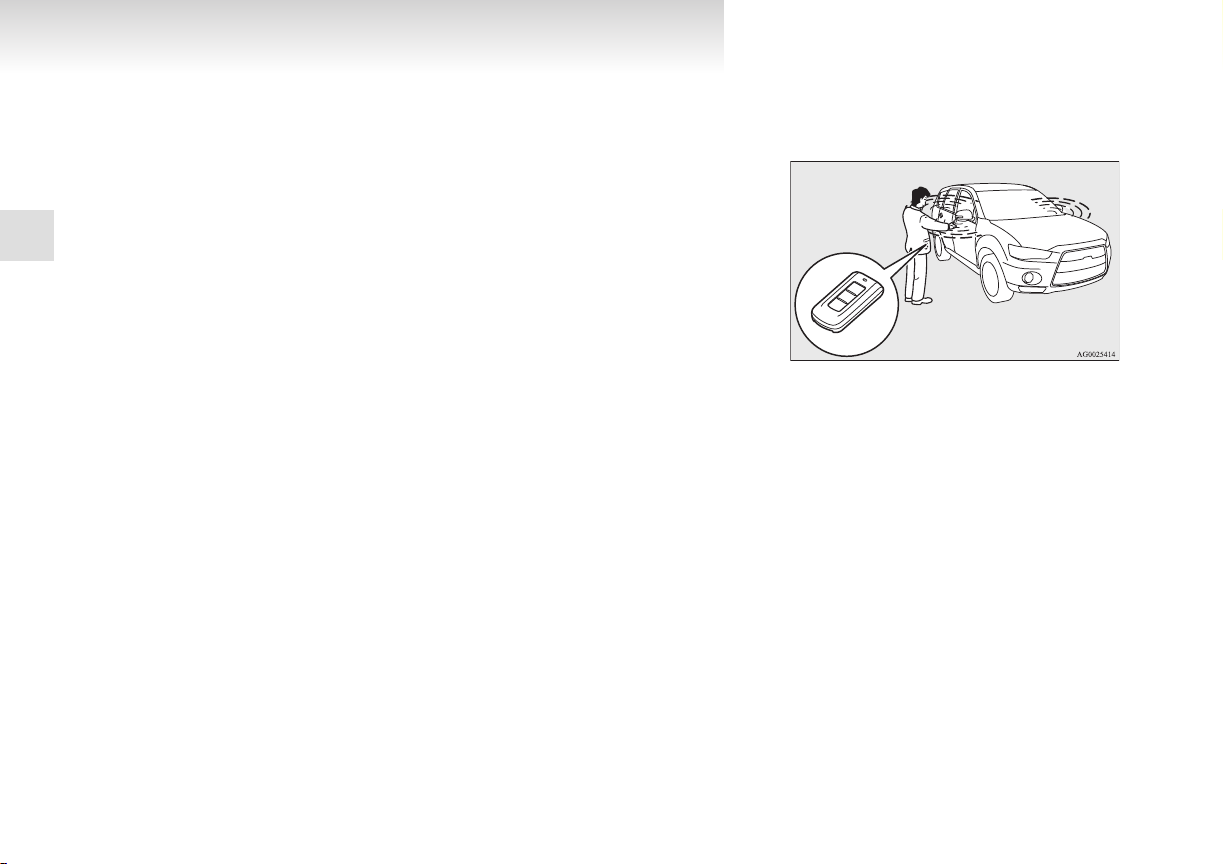
Keyless entry system*
Press
the remote control switch, and all doors and
the tailgate will be locked or unlocked as desired. It
is also possible to operate the outside rear-view mirrors.
1- LOCK switch
UNLOCK switch
23- Indication lamp
E00300302418
To lock
Press the LOCK switch (1). All the doors and the
tailgate will be locked. The turn-signal lamps will
blink once when the doors and the tailgate are locked.
NOTE
With a vehicle that has a Dead Lock System,
l
pressing the LOCK switch (1) two times in
succession causes the Dead Lock System to
be set. (Refer to “Setting the system” on
page 1-29.)
To unlock
Press
the UNLOCK switch (2). All the doors and
the tailgate will be unlocked. If the doors and tailgate are unlocked when the front room lamp switch
is in the “DOOR” position or the rear room lamp
switch is in the middle (•) position, the room lamp
will illuminate for approximately 15 seconds and
the turn-signal lamps will blink twice.
The position and tail lamps can also be set to turn
on for about 30 seconds. Refer to “Instruments and
controls: Welcome light” on page 3-45.
NOTE
Except for vehicles equipped with a Dead
l
Lock System, the door and tailgate unlock
function can be set so that only the driver’s
door unlocks when the UNLOCK switch (2)
is pressed once.
If the door and tailgate unlock function is set
to work as described above, all the doors and
the tailgate unlock when the UNLOCK
switch is pressed two times in succession.
Refer to “Setting of door and tailgate unlock
function” on page 1-05.
The indication lamp (3) comes on each time
l
a switch is pressed.
For vehicles equipped with the mirror retrac-
l
tor switch, the outside rear-view mirrors auto-
matically retract or extend when all the doors
and tailgate are locked or unlocked using the
remote control switches of the keyless entry
system.
Refer to “Starting and driving: Outside rear-
view mirrors” on page 4-11.
1-04
Page 27

the UNLOCK switch (2) is pressed and no
OGXE12E1
If
l
door or tailgate is opened within approximately 30 seconds, relocking will automatically
occur.
It is possible to modify functions as follows:
l
For further information, please contact your
MITSUBISHI MOTORS Authorized Service
Point.
On vehicles equipped with MITSUBISHI
Multi-Communication System (MMCS),
screen operations can be used to make the adjustment. Refer to the separate owner’s manual for details.
• The time for automatic relocking can be
changed.
• The confirmation function (flashing of
the turn-signal lamps) can be set to operate only when the doors and backdoor are
locked or only when the doors and backdoor are unlocked.
• The confirmation function (this indicates
locking or unlocking of the doors and tailgate with the flash of the turn-signal
lamps) can be deactivated.
• The number of times the turn-signal
lamps are flashed by the confirmation
function can be changed.
Operation of the Dead Lock System
In a vehicle that has a Dead Lock System, it is possible to set the Dead Lock System using the remote
controller.
(Refer to “Dead Lock System” on page 1-29.)
Operation of the outside rear-view mirrors
(Vehicles equipped with mirror re-
tractor switch)
To fold
Within 30 seconds of locking the doors and tailgate
using the LOCK switch (1), press the LOCK
switch twice rapidly to fold the outside rear-view
mirrors.
To extend
Within 30 seconds of unlocking the doors and tailgate using the UNLOCK switch (2), press the UNLOCK switch twice rapidly to return the outside
rear-view mirrors to their extended positions.
The outside rear-view mirrors are not initially set
to
work as described above. If you want them to
work as described above, you need to set them so
that they do not retract/extend when the doors and
tailgate are locked/unlocked using the keyless entry system or keyless operation system.
Refer to “Starting and driving: Outside rear-view
mirrors” on page 4-11.
For details, please consult a MITSUBISHI
MOTORS Authorized Service Point.
In a vehicle equipped with the MITSUBISHI Multi-Communication System (MMCS), it is possible
to change the setting by means of screen operations.
Refer to the separate owner’s manual for details.
NOTE
The
keyless entry system does not operate in
l
the following conditions:
• The key is left in the ignition switch.
• The door or tailgate is open.
E00310800122
Locking and unlocking
remote control switch will operate with-
The
l
in approximately 4 m from the vehicle. However, the operating range of the remote control switch may change if the vehicle is located near a power station, or radio/TV broadcasting station.
If either of the following problems occurs,
l
the battery may be exhausted.
• The remote control switch is operated at
the correct distance from the vehicle, but
the doors and tailgate are not locked/unlocked in response.
• The indication lamp (3) is dim or does
not come on.
For further information, please contact
your MITSUBISHI MOTORS Authorized Service Point.
If you replace the battery yourself, refer
to “Procedure for replacing the remote
control switch battery” on page 1-06.
If your remote control switch is lost or dam-
l
aged, please contact your MITSUBISHI
MOTORS Authorized Service Point for a replacement remote control switch.
If you wish to add a remote control switch,
l
we recommend you to contact a
MITSUBISHI MOTORS Authorized Service
Point.
A maximum of 8 remote control switches are
available for your vehicle.
Setting of door and tailgate unlock function (Except for vehicles equipped with a Dead Lock System)
The door and tailgate unlock function can be set to
the following two conditions.
E00310300185
1
1-05
Page 28
Locking and unlocking
OGXE12E1
Each time the door and tailgate unlock function is
set, a chime will sound to tell you the condition of
the door and tailgate unlock function.
Number of
chimes
One chime All doors and the tailgate unlock
Two chimes Driver’s door unlock only
1
1. Remove the key from the ignition switch.
2. Place the combination headlamps and dipper
switch in the “OFF” position, and leave the
driver’s door open.
3. Press the LOCK switch (1) for 4 to 10 seconds and press the UNLOCK switch (2) during this time.
4. Release in sequence the LOCK and UNLOCK switches within 10 seconds of pressing the LOCK switch in step 3.
Condition
NOTE
On vehicles equipped with MITSUBISHI
l
Multi-Communication System (MMCS),
screen operations can be used to make the adjustment. Refer to the separate owner’s manual for details.
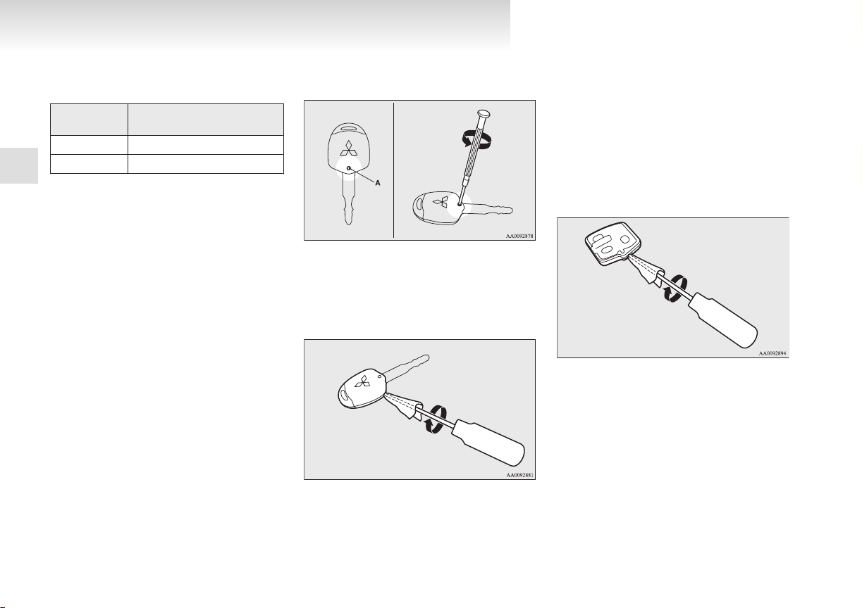
Procedure for replacing the remote control switch battery
1. Before
replacing the battery, remove static
electricity from your body by touching a metal part such as doorknob of the room.
E00309500158
2. Remove
3. With
the screw (A) from the remote con-
trol switch.
the MITSUBISHI mark facing you, insert the cloth-covered tip of a straight blade
(or minus) screwdriver into the notch in the
remote control switch case and use it to open
the case.
NOTE
Be
sure to perform the procedure with the
l
MITSUBISHI mark facing you. If the
MITSUBISHI mark is not facing you when
you open the remote control switch case, the
switches may come out.
4. Remove the remote control transmitter from
the remote control switch case. Then, open
the remote control transmitter using the method described in step 3.
5. Remove the old battery.
1-06
Page 29
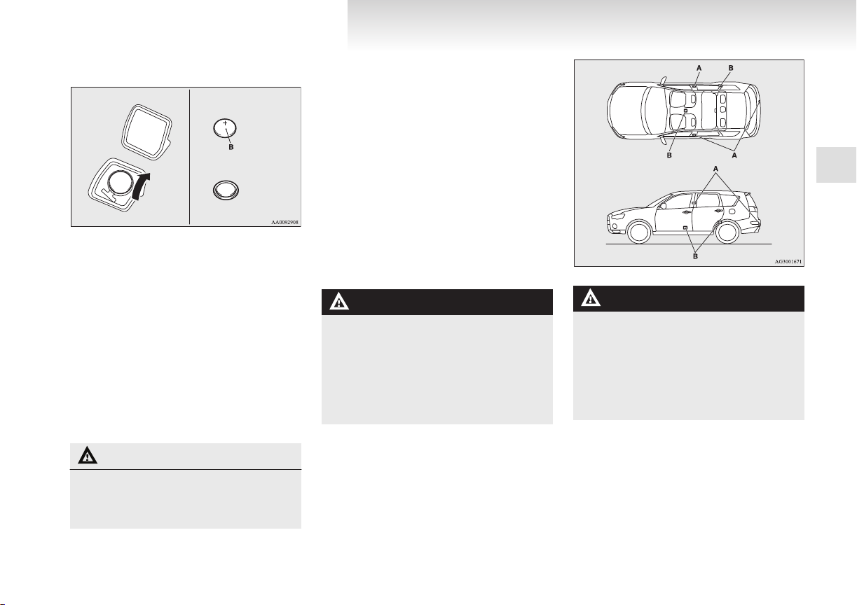
6. Install a new battery with the + side (B) down.
Coin type battery
CR1616
- side
+ side
OGXE12E1
7. Close the remote control transmitter firmly.
8. Place the remote control transmitter in the remote control switch case, then securely close
the remote control switch case.
9. Attach the screw (A) removed in step 2.
10. Check the keyless entry system to see that it
works.
NOTE
You may purchase a replacement battery at
l
an electric appliance store.
A MITSUBISHI MOTORS Authorized Serv-
l
ice Point can replace the battery for you if
you prefer.
CAUTION
When
l
the remote control switch case is
opened, be careful to keep water, dust,
etc. out. Also, do not touch the internal
components.
Keyless operation system*
The
keyless operation system allows you to lock
and unlock the doors and tailgate and start the engine simply by carrying the keyless operation key
with you.
The keyless operation key can also be used as the
keyless entry system remote control switch.
Refer to “Keyless operation system: Keyless entry
system” on page 1-24.
The driver should always carry the keyless operation key. This key is necessary for locking and unlocking the doors and tailgate, starting the engine
and otherwise operating the vehicle, so before locking and leaving the vehicle, be sure to check that
you have the keyless operation key.
E00305600539
WARNING
with implantable cardiac pacemak-
People
l
ers or implantable cardiovascular-defibrillators should not go near the exterior
transmitters (A) or the interior transmitters (B). The radio waves used by the keyless operation system could adversely affect implantable cardiac pacemakers or
implantable cardiovascular-defibrillators.
Locking and unlocking
WARNING
When
l
using electro-medical devices other
than implantable cardiac pacemakers or
implantable cardiovascular-defibrillators, contact the electromedical device
manufacturer ahead of time to determine
the affects of radio waves on the devices.
Electromedical device operations could
be affected by radio waves.
You can limit the possible operations of the
keyless
operation system in the following
ways. (The keyless operation system can be
used as a keyless entry system.) Consult a
MITSUBISHI MOTORS Authorized Service
Point.
• You can limit operations to locking and
unlocking the doors and tailgate.
1
1-07
Page 30
Locking and unlocking
OGXE12E1
• You can limit operations to starting the en-
• The keyless operation system can be disa-
When keyless operation system operations
are modified, the transmitters operate as follows.
1
• Only locking and unlocking doors or tail-
• Only starting the engine: interior transmit-
NOTE
The keyless operation key uses an ultra-weak
l
electromagnetic wave. In the following cases, the keyless operation system may not operate properly or may be unstable.
• When there is equipment nearby that
• The keyless operation system is carried to-
• The keyless operation key is touching or
• A keyless entry system is being used near-
• When the keyless operation key battery is
gine.
bled.
gate: exterior and interior transmitters
ter
emits strong radio waves, such as: a power station, a radio/TV broadcasting station or an airport.
gether with a communications device
such as a cellular phone or radio set, or
with an electronic device such as a personal computer.
covered by a metal object.
by.
worn out.
• When
the keyless operation key is placed
in an area with strong radio waves or noise.
In such cases, use the emergency key.
Refer to “To operate without using the
keyless operation function” on page
1-18.
Because the keyless operation key receives
l
signals in order to communicate with the transmitters in the vehicle, the battery continually
wears down regardless of keyless operation
key use. The battery life is 1 to 3 years, depending on usage conditions. When the battery wears out, have it replaced at a
MITSUBISHI MOTORS Authorized Service
Point.
Because the keyless operation key continual-
l
ly receives signals, strong radio wave reception could affect battery wear. Do not leave
the key near a TV, personal computer, or other electronic device.
Operating range of the keyless operation system
If you are carrying the keyless operation key, enter
the
operating range of the keyless operation system, and press the driver’s or front passenger’s
door lock/unlock switch, the tailgate LOCK switch
or the tailgate OPEN switch, the ID code for your
key is verified.
E00305700471
You can only lock and unlock the doors and tailgate
and start the engine if the ID codes of your key-
less operation key and the vehicle match.
NOTE
If
the keyless operation key battery is wear-
l
ing out or there are strong electromagnetic
waves or noise present, the operating range
may become smaller and operation may become unstable.
1-08
Page 31

Operating range for locking and unlocking the
Driver’s or front passenger’s door
lock/unlock switches
Tailgate switches
OGXE12E1
doors and tailgate
The operating range is about 70 cm from the driver’s door handle, front passenger’s door handle,
and tailgate handle.
*: Forward direction
Operating range
:
E00306200444
the keyless operation key is within the op-
If
l
erating range, even someone not carrying the
key can lock and unlock the doors and tailgate by pressing the driver’s or front passenger’s door lock/unlock switch, the tailgate
LOCK switch or the tailgate OPEN switch.
Operating range for starting the engine
The operating range is the interior of the vehicle.
E00306300184
Locking and unlocking
To operate using the keyless operation function
Locking the doors and tailgate
you are carrying the keyless operation key,
When
if you press the driver’s or front passenger’s door
lock/unlock switch (A), or the tailgate LOCK
switch (B) within the operating range, the doors
and the tailgate are locked.
The turn-signal lamps will blink once.
Also refer to “Locking and unlocking: Doors, Central door locks, Split tailgate” on pages 1-26,
1-28 and 1-31.
E00305800616
1
NOTE
Locking
l
when the door or tailgate is operated while
the keyless operation key is being detected.
Operation may not be possible if you are too
l
close to the front door, door window, or tailgate.
Even if the keyless operation key is within
l
70 cm of the driver’s door handle, front passenger’s door handle, or tailgate handle, if
the key is near to the ground or high up, the
system may not operate.
and unlocking are only possible
*: Forward direction
Operating range
:
NOTE
Even
if it is within the operating range, if the
l
keyless operation key is in a small item holder such as the glove box, on top of the instrument panel, door pocket or in the luggage
area, it may be impossible to start the engine.
If you are too close to the door or door win-
l
dow, the engine may start even though the
keyless operation key is outside the vehicle.
1-09
Page 32

Driver’s and front passenger’s door lock/unlock switches
Tailgate OPEN switch
Locking and unlocking
OGXE12E1
NOTE
For
vehicles equipped with the mirror retrac-
l
tor switch, the outside rear-view mirrors automatically retract when all the doors and tailgate are locked using the keyless operation
function.
Refer to “Starting and driving: Outside rearview mirrors” on page 4-11.
1
With a vehicle that has a Dead Lock System,
l
pressing the driver’s or front passenger’s
door lock/unlock switch (A), or the tailgate
LOCK switch (B) two times in succession
causes the Dead Lock System to be set. (Refer to “Setting the system” on page 1-29.)
The keyless operation function does not oper-
l
ate under the following conditions:
• The keyless operation key is inside the vehicle.
• A door or the tailgate is open or ajar.
• The ignition switch is not in the “LOCK”
position.
• The emergency key is in the ignition
switch.
The tailgate OPEN switch (C) can be used to
l
check that the vehicle is locked properly.
Press the tailgate OPEN switch within approximately 3 seconds of locking the vehicle. If
you wait longer than 3 seconds and press the
tailgate OPEN switch, the doors and tailgate
will be unlocked.
time allowed for checking that the vehi-
The
l
cle is locked can be adjusted. For further information, please contact your MITSUBISHI
MOTORS Authorized Service Point.
On vehicles equipped with MITSUBISHI
Multi-Communication System (MMCS),
screen operations can be used to make the adjustment. Refer to the separate owner’s manual for details.
Unlocking the doors and tailgate
When you are carrying the keyless operation key,
if you press the driver’s or front passenger’s door
lock/unlock switch (A), or the tailgate OPEN
switch (B) within the operating range, all the doors
and the tailgate are unlocked.
If the front room lamp switch is in the “DOOR” position or the rear room lamp switch is in the middle
(•) position at this time, the room lamp will turn on
for 15 seconds. The turn-signal lamps will blink
twice.
If the driver’s or front passenger’s door lock/unlock switch is pressed and any of the doors or tailgate is not opened within approximately 30 seconds, relocking will automatically occur.
Also refer to “Locking
tral door locks, Split tailgate” on pages 1-26,
1-28 and 1-31.
and unlocking: Doors, Cen-
NOTE
For
vehicles equipped with the mirror retrac-
l
tor switch, the outside rear-view mirrors automatically extend when all the doors and tailgate are unlocked using the keyless operation
function.
Refer to “Starting and driving: Outside rearview mirrors” on page 4-11.
1-10
Page 33

for vehicles equipped with a Dead
OGXE12E1
Except
l
Lock System, the keyless operation function
can be set so that only the driver’s door unlocks when the driver’s door lock/unlock
switch is pressed.
If the keyless operation function is set to
work as described above, all the doors and
the tailgate unlock when the driver’s door
lock/unlock switch is pressed two times in
succession.
Refer to “Setting of door and tailgate unlock
function” on page 1-25.
The keyless operation function does not oper-
l
ate under the following conditions:
• A door or the tailgate is open or ajar.
• The ignition switch is not in the “LOCK”
position.
• The emergency key is in the ignition
switch.
In order to make it possible to check that the
l
doors and tailgate are locked, you cannot unlock them by using the tailgate OPEN switch
for 3 seconds after locking them.
The time allowed for checking that the vehi-
l
cle is locked can be adjusted. For further information, please contact your MITSUBISHI
MOTORS Authorized Service Point.
On vehicles equipped with MITSUBISHI
Multi-Communication System (MMCS),
screen operations can be used to make the adjustment. Refer to the separate owner’s manual for details.
The time between unlocking and automatic
l
locking can be adjusted. Consult a
MITSUBISHI MOTORS Authorized Service
Point.
On vehicles equipped with MITSUBISHI
Multi-Communication System (MMCS),
screen operations can be used to make the adjustment. Refer to the separate owner’s manual for details.
Operation confirmation when locking and unlocking
Operation can be confirmed as shown below. However, the room lamp will only illuminate if the
front room lamp switch is in the “DOOR” position
or the rear room lamp switch is in the middle (•) position.
When locking: The turn-signal lamps will
When unlocking: The room lamp will illumi-
blink once.
nate
for approximately 15 seconds, the turn-signal lamps
will blink twice.
NOTE
Functions
l
For further information, please contact your
MITSUBISHI MOTORS Authorized Service
Point.
On vehicles equipped with MITSUBISHI
Multi-Communication System (MMCS),
screen operations can be used to make the adjustment. Refer to the separate owner’s manual for details.
can be modified as stated below.
Locking and unlocking
• Set the confirmation function (blinking of
turn-signal lamps) to operate only
the
when the vehicle is locked or only when
the vehicle is unlocked.
• Disable the operation confirmation func-
tion (blinking of the turn-signal lamps).
• Change the number of blinks for the oper-
ation confirmation function (blinks of the
turn-signal lamps).
Operation of the Dead Lock System
With a vehicle that has a Dead Lock System, it is
possible to set the Dead Lock System using the driver’s or front passenger’s door lock/unlock switch,
or the tailgate LOCK switch.
(Refer to “Dead Lock System” on page 1-29.)
Electronic immobilizer (Anti-theft starting system)
The electronic immobilizer has been designed to significantly
The purpose of the system is to immobilize the vehicle if an invalid start is attempted. A valid start
attempt can only be achieved (subject to certain conditions) using a keyless operation system “registered” to the immobilizer system.
All of the keys provided with your new vehicle
have been programmed into the vehicle’s electronics. Refer to “Keyless operation system: Ignition
switch” on pages 1-12 and 1-19.
reduce the possibility of vehicle theft.
E00306400488
1
1-11
Page 34

Locking and unlocking
OGXE12E1
NOTE
If
you lose one of the keyless operation keys,
l
contact a MITSUBISHI MOTORS Authorized Service Point as soon as possible.
To obtain a replacement or extra spare key,
take your vehicle and all remaining keys to
your MITSUBISHI MOTORS Authorized
Service Point. All the keys have to be re-reg-
1
istered in the immobilizer computer unit.
The immobilizer can register up to 4 different keys.
Ignition switch
In order to prevent theft, the engine will not start unless
a preregistered keyless operation key is used.
(Engine immobilizer function)
Provided you are carrying the keyless operation
key, you can start the engine by turning the ignition
switch.
Also refer to “Starting and driving: Starting the engine” on pages 4-15 and 4-16.
E00306500434
LOCK (PUSH ON)
When the ID code verification inside the vehicle
produces a match, the steering wheel lock is released and the ignition switch can be turned.
ACC
The engine is stopped, but the audio system and other electric devices can be operated.
ON
The engine is running, and all the vehicle’s electrical devices can be operated.
START
The starter motor operates. Once the engine starts,
let go of the key. The key will automatically return
to the “ON” position.
NOTE
Your vehicle is equipped with an electronic
l
immobilizer. To start the engine, the ID code
which the transponder inside the key sends
must match the one registered in the immobilizer computer.
(Refer to “Electronic immobilizer (Anti-theft
starting system)” on page 1-11.)
When turning from “LOCK” (PUSH OFF) to “ACC”
Push the ignition switch and turn it slowly.
A- Steering wheel locked
B-
Steering wheel released
E00306600031
NOTE
If the ignition switch does not turn from
l
“LOCK” (PUSH OFF) to “ACC”, press the
ignition switch again, slightly move the steering wheel left and right, and then turn the ignition switch.
The ignition switch cannot be turned if the
l
keyless operation key is not in the vehicle.
Refer to “Operating range for starting the engine” on page 1-09.
LOCK (PUSH OFF)
The position in which the steering wheel is locked.
1-12
When turning from “ACC” to “LOCK”
[Vehicles with M/T]
Put
the gearshift lever into the “N” (Neutral) position, and slowly turn the ignition switch to the
“LOCK” position while pressing it.
[Vehicles with A/T, CVT or Twin Clutch SST]
E00306700061
Page 35

First, set the selector lever (A/T or CVT) or the gear-
OGXE12E1
shift lever (Twin Clutch SST) to the “P” (PARK)
positon, and then slowly turn the ignition switch to
the “LOCK” position while pressing it.
CAUTION
Do not leave the ignition switch in the
l
“ON” or “ACC” position for a long time
when the engine is not running, doing so
will cause the battery to be discharged.
Do not turn the ignition switch to the
l
“START” position when the engine is running, doing so could damage the starter
motor.
Type 1
Type 2
Type 1
Locking and unlocking
There is a fault in the keyless operation system.
1
NOTE
On
vehicles with A/T, CVT or Twin Clutch
l
SST, the ignition switch cannot be turned to
the “LOCK” position unless the selector lever (A/T or CVT) or the gearshift lever (Twin
Clutch SST) is in the “P” (PARK) position.
CAUTION
not turn the ignition switch to the
Do
l
“LOCK” position while driving. The steering wheel will be locked, causing loss of
control.
If the engine is stopped while driving, the
l
brake servo mechanism will cease to function and braking function will deteriorate. Also, the power steering system will
not function and it will require greater
manual effort to operate the steering.
Warning activation
In order to prevent vehicle theft or the accidental operation
of the keyless operation system, the buzzer
and the display on the information screen in the multi-information display are used to alert the driver.
If a warning is activated, always check the vehicle
and the keyless operation key. The warning is also
displayed if there is a fault in the keyless operation
system.
If any of the following warnings are activated,
please contact a MITSUBISHI MOTORS Authorized Service Point.
E00305900590
Type 2
In the following cases, a warning is activated, but it
can be cancelled if the correct actions are followed.
l
The battery in the keyless operation
key has worn out.
ID codes for the keyless operation key
The
and vehicle do not match.
1-13
Page 36

Locking and unlocking
OGXE12E1
1
Type 1
You could be carrying another key-
operation key with a different
Type 2
Type 1
Type 2
l
less
code, or the keyless operation key
could be outside the operating range.
Refer to “Keyless operation key takeout monitoring system” on page
1-14.
Even
though you press the driver’s or front
passenger’s door lock/unlock switch, or the
tailgate LOCK switch, the doors and tailgate
are not locked.
Type 1
Type 2
Type 1
Type 2
Type 1
Type 2
Refer to “Key lock-in prevention system” on page 1-15.
Refer to “Door
tem” on page 1-15.
Refer to “Ignition
minder system” on page 1-15.
ajar prevention sys-
switch turn-off re-
Keyless operation key take-out monitoring system
Type 1
Type 2
When the vehicle is parked with the ignition switch
in any position other than “LOCK” (PUSH OFF),
if you close the door after opening any of the doors
and taking the keyless operation key out of the vehicle, a warning displays and the buzzer sounds 4
times.
E00308000260
NOTE
If you take the keyless operation key out of
l
the vehicle through a window without opening a door, the keyless operation key takeout monitoring system does not operate.
1-14
Page 37

is possible to change the setting to make
OGXE12E1
It
l
the keyless operation key take-out monitoring system operate if you take the keyless operation key out from the vehicle through a
window without opening a door. For further
information, please contact your
MITSUBISHI MOTORS Authorized Service
Point.
Even if you have the keyless operation key
l
within the engine start operating range, if the
keyless operation key and vehicle ID codes
cannot be matched, for example due to the
ambient environment or electromagnetic conditions, the warning may be activated.
Key lock-in prevention system
Type 1
Type 2
E00308100506
When the ignition switch is in the “LOCK” (PUSH
OFF) position, if you close all the doors and the tailgate with the keyless operation key left in the vehicle and you try to lock the doors and tailgate by
pressing the driver’s or front passenger’s door lock/
unlock switch, or the tailgate LOCK switch, a warning is issued with the warning display and the buzzer buzzing for about 3 seconds and you cannot
lock the doors and tailgate.
NOTE
Make sure you have the keyless operation
l
key with you before locking the doors. Even
if you leave the keyless operation key inside
the vehicle, it is possible that the doors will
lock depending on the surrounding environment and wireless signal conditions.
Door ajar prevention system
Type 1
Type 2
E00308200451
Locking and unlocking
When the ignition switch is in the “LOCK” (PUSH
OFF) position, if you try to lock the doors and tailgate by pressing the driver’s or front passenger’s
door lock/unlock switch, or the tailgate LOCK
switch with one of the doors or the tailgate not completely closed, a warning is issued with the warning display and the buzzer buzzing for about 3 seconds and you cannot lock the doors and tailgate.
Ignition switch turn-off reminder system
Type 1
Type 2
When the ignition switch is in any position other
than
the “LOCK” (PUSH OFF) position, if you
close all the doors and the tailgate then try to lock
the doors and tailgate by pressing the driver’s or
front passenger’s door lock/unlock switch, or the
tailgate LOCK switch, a warning is issued with the
warning display and the buzzer buzzing for about 3
seconds and you cannot lock the doors and tailgate.
E00308300452
1
1-15
Page 38

Locking and unlocking
OGXE12E1
Steering wheel lock
To lock
Turn the steering wheel until it is locked.
To unlock
the ignition switch to the “ACC” position
Turn
while moving the steering wheel slightly right and
1
left.
CAUTION
the key with you when leaving the
Carry
l
vehicle.
If your vehicle needs to be towed, turn
the ignition switch to the “ACC” position
to unlock the steering wheel.
E00306800192
Starting
Tips for starting
Do not operate the starter motor continuous-
l
ly longer than 10 seconds; doing so could
run down the battery. If the engine does not
start, turn the ignition switch back to
“LOCK”, wait a few seconds, and then try
again.
Trying repeatedly with the starter motor still
turning will damage the starter mechanism.
On vehicles equipped with the Twin Clutch
l
SST, the following may occur after the engine is started, but they do not indicate an abnormality.
• You may hear operational sounds of the
Twin Clutch SST and you may feel vibration in the vehicle body.
• If you shift the gearshift lever into the
“N” (NEUTRAL) position and depress
the accelerator pedal, increases in the engine speed will be limited.
[Diesel-powered vehicles with M/T]
l
While the vehicle is stationary with the
clutch pedal fully depressed, the engine revolutions do not rise to over 3,000 rpm in order
to protect the engine even if the accelerator
pedal is depressed.
WARNING
run the engine in a closed or poor-
Never
l
ly ventilated area any longer than is needed to move your vehicle in or out of the
area. Carbon monoxide gases are odourless and can be fatal.
E00306900441
CAUTION
Never attempt to start the engine by push-
l
ing or pulling the vehicle.
Do not run the engine at high rpm or
l
drive the vehicle at high speed until the engine has had a chance to warm up.
Release the ignition switch as soon as the
l
engine starts to avoid damaging the starter motor.
If your vehicle is equipped with a turbo-
l
charger, do not stop the engine immediately after high-speed or uphill driving.
First allow the engine to idle to give the
turbocharger a chance to cool down.
Starting the engine (petrol-powered vehicles)
The starting procedure is as follows:
1.
Fasten the seat belt.
2. Make sure the parking brake is applied.
3. Depress and hold the brake pedal.
4. Fully depress the clutch pedal (M/T).
5. On vehicles equipped with M/T, place the
gearshift lever in the “N” (Neutral) position.
E00307000739
1-16
Page 39

On vehicles equipped with A/T or CVT,
Vehicles with M/T Vehicles with A/T or CVT
Vehicles with M/T Vehicles with
Twin Clutch SST
OGXE12E1
make sure the selector lever is in the “P”
(PARK) position.
Using the MIVEC engine (3000 models)
MIVEC engine automatically switches its in-
The
take-valve control between a low-speed mode and
a high-speed mode in accordance with driving conditions for maximum engine performance.
NOTE
To protect the engine, the high-speed mode
l
may not be selected while the engine coolant
temperature is low. In such a case, the engine
revolutions do not rise to over 5,000 rpm
even if the accelerator pedal is depressed.
Locking and unlocking
On vehicles equipped with Twin Clutch
make sure the gearshift lever is in the
SST,
“P” (PARK) position.
1
NOTE
On
vehicles equipped with A/T or CVT, the
l
starter will not operate unless the selector lever is in the “P” (PARK) or “N” (NEUTRAL)
position.
For safety reasons, start the engine in the “P”
(PARK) position so that the wheels are locked.
6. After turning the ignition switch to the “ON”
position, make certain that all warning lamps
are functioning properly before starting the
engine.
7. Turn the ignition switch to the “START” position without depressing the accelerator pedal, and release it when the engine starts.
NOTE
Minor noises may be heard on engine start-
l
up. These will disappear as the engine warms
up.
Starting the engine (diesel-powered vehicles)
1. Fasten the seat belt.
2.
Make sure the parking brake is applied.
3. Depress and hold the brake pedal.
4. Fully depress the clutch pedal (M/T).
E00307000625
NOTE
On vehicles with the Auto Stop & Go
l
(AS&G) system, the starter will not operate
unless the clutch pedal is fully depressed
(Clutch interlock).
5. On vehicles equipped with M/T, place the
gearshift lever in the “N” (Neutral) position.
NOTE
On
vehicles with Twin Clutch SST, the start-
l
er will not operate unless the gearshift lever
is in the “P” (PARK) position or the gearshift lever is in the “N” (NEUTRAL) position with the brake pedal depressed.
For safety reasons, start the engine in the “P”
(PARK) position so that the wheels are locked.
6. Turn the ignition switch to the “ON” position.
The diesel preheat indication lamp will first
illuminate, and then after a short time go out,
indicating that preheating is completed.
NOTE
If the engine is cold, the diesel preheat indi-
l
cation lamp is on for a longer time.
1-17
Page 40

Locking and unlocking
OGXE12E1
On vehicles with Twin Clutch SST, when the
l
l
1
7. Turn the ignition switch to the “START” po-
has not been started within about 5 sec-
engine
onds after the diesel preheat indication lamp
went out, return the ignition switch to the
“LOCK” position. Then, turn the switch to
the “ON” position to preheat the engine again.
When the engine is warm, the diesel preheat
indication lamp does not come on even if the
ignition switch is placed in the “ON” position.
Start the engine by turning the ignition
switch right to the “START” position.
sition without depressing the accelerator pedal, and release it when the engine starts.
NOTE
Minor noises may be heard on engine start-
l
up. These will disappear as the engine warms
up.
Using the MIVEC engine
The MIVEC engine automatically switches its intake-valve control between a low-speed mode and
a high-speed mode in accordance with driving conditions for maximum engine performance.
NOTE
To protect the engine, the high-speed mode
l
may not be selected while the engine coolant
temperature is low.
To operate without using the keyless operation function
Emergency key
The emergency key is built into the keyless operation
key. If the keyless operation function cannot
be used, for example because the keyless operation
key battery has worn out or the vehicle battery is
flat, you can lock and unlock the driver’s door and
start the engine with the emergency key. To use the
emergency key (A), unlock the lock knob (B) and
remove it from the keyless operation key (C).
NOTE
Only
use the emergency key for emergen-
l
cies. If the keyless operation key battery
wears out, replace it as quickly as possible so
that you can use the keyless operation key.
After using the emergency key, always re-
l
turn it into the keyless operation key.
E00306000019
E00307200353
The glove box can only be locked or un-
l
locked with the emergency key. When leaving your key at a hotel reception or lending
your vehicle to someone else, take out the
emergency key as necessary and hand over
only the keyless operation key.
Locking and unlocking the driver’s door
Turning the emergency key in the forward direction locks the door, and turning it in the rear direction unlocks the door. Also refer to “Locking and
unlocking: Doors” on page 1-26.
1- Lock
Unlock
2-
Electronic immobilizer (Anti-theft starting system)
The electronic immobilizer has been designed to significantly
The purpose of the system is to immobilize the vehicle if an invalid start is attempted. A valid start
attempt can only be achieved (subject to certain conditions) using a keyless operation system and emergency key “registered” to the immobilizer system.
reduce the possibility of vehicle theft.
E00307300400
1-18
Page 41

All of the keys provided with your new vehicle
OGXE12E1
have been programmed into the vehicle’s electronics. Refer to “Keyless operation system: Ignition
switch” on pages 1-12 and 1-19.
NOTE
If you lose one of the keyless operation keys,
l
contact a MITSUBISHI MOTORS Authorized Service Point as soon as possible.
To obtain a replacement or extra spare key,
take your vehicle and all remaining keys to
your MITSUBISHI MOTORS Authorized
Service Point. All the keys have to be re-registered in the immobilizer computer unit.
The immobilizer can register up to 4 different keys.
Ignition switch
To prevent vehicle theft, only the emergency key
with
the preregistered keyless operation key inserted can start the engine. (Electronic immobilizer
function)
Also refer to “Starting and driving: Starting the engine” on pages 4-15 and 4-16.
E00307400430
LOCK
The engine is stopped and the steering wheel
locked. The emergency key can be inserted and removed in this position.
ACC
The engine is stopped, but the audio system and other electrical devices can be operated.
ON
The engine is running, and all the vehicle’s electrical devices can be operated.
START
The starter motor operates. After the engine has started, release the emergency key and it will automatically return to the “ON” position.
NOTE
The keyless operation key is equipped with
l
an electronic immobilizer. To start the engine, the ID code which the transponder inside the key sends must match the one registered in the immobilizer computer.
Refer to “Electronic immobilizer (Anti-theft
starting system)” on page 1-18.
When turning from “LOCK” to “ACC”
1. Take the emergency key out of the keyless operation key. Refer to “Emergency key” on
page 1-18.
Locking and unlocking
2. Remove
3. Insert
the ignition switch cover while press-
ing the lock release button (A).
the emergency key into the ignition
switch, and turn while pushing.
1
NOTE
If
the ignition switch will not turn from the
l
“LOCK” to the “ACC” position, lightly turn
the steering wheel right and left while turning the ignition switch.
1-19
Page 42

Locking and unlocking
OGXE12E1
When turning from “ACC” to “LOCK”
1. [Vehicles with M/T]
While pushing the ignition switch, turn to the
“LOCK” position and pull out the key.
[Vehicles with A/T, CVT or Twin Clutch SST]
First, set the selector lever (A/T or CVT) or
the gearshift lever (Twin Clutch SST) to the
“P” (PARK) positon, and then push the emer-
1
gency key in at the “ACC” position and keep
it depressed until it is turned to the “LOCK”
position, and remove.
2. Install the ignition switch cover.
3. Return the emergency key into the keyless operation key.
NOTE
On vehicles with A/T, CVT or Twin Clutch
l
SST, the emergency key with keyless operation key cannot be removed unless the selector lever (A/T or CVT) or the gearshift lever
(Twin Clutch SST) is set to the “P” (PARK)
position.
When not using the emergency key, always
l
install the ignition switch cover. Otherwise,
there is a danger of dirt or dust getting into
the keyhole of the ignition switch and causing a malfunction.
CAUTION
Do
not remove the emergency key from
l
the ignition switch while driving. The
steering wheel will be locked, causing loss
of control.
1-20
CAUTION
If the engine is stopped while driving, the
l
brake servomechanism will cease to function and braking efficiency will deteriorate. Also, the power steering system will
not function and it will require greater
manual effort to operate the steering.
Do not leave the emergency key in the
l
“ON” or “ACC” position for a long time
when the engine is not running, doing so
will cause the battery to be discharged.
Do not turn the emergency key to the
l
“START” position when the engine is running, doing so could damage the starter
motor.
Steering wheel lock
To lock
Turn the emergency key to the “LOCK” position.
Turn the steering wheel until it is locked.
E00307500095
To unlock
Turn the emergency key to the “ACC” position
while moving the steering wheel slightly right and
left.
CAUTION
Remove the emergency key when leaving
l
the vehicle.
In some countries, it is prohibited to leave
the key in the vehicle when parked.
Starting
Tips for starting
Do
not operate the starter motor continuous-
l
ly longer than 10 seconds; doing so could
run down the battery. If the engine does not
start, turn the ignition switch back to
“LOCK”, wait a few seconds, and then try
again.
Trying repeatedly with the starter motor still
turning will damage the starter mechanism.
On vehicles equipped with the Twin Clutch
l
SST, the following may occur after the en-
E00307600403
Page 43

gine is started, but they do not indicate an ab-
Vehicles with M/T Vehicles with A/T or CVT
OGXE12E1
normality.
• You may hear operational sounds of the
Twin Clutch SST and you may feel vibration in the vehicle body.
• If you shift the gearshift lever into the
“N” (NEUTRAL) position and depress
the accelerator pedal, increases in the engine speed will be limited.
[Diesel-powered vehicles with M/T]
l
While the vehicle is stationary with the
clutch pedal fully depressed, the engine revolutions do not rise to over 3,000 rpm in order
to protect the engine even if the accelerator
pedal is depressed.
WARNING
run the engine in a closed or poor-
Never
l
ly ventilated area any longer than is needed to move your vehicle in or out of the
area. Carbon monoxide gases are odourless and can be fatal.
CAUTION
Never attempt to start the engine by push-
l
ing or pulling the vehicle.
Do not run the engine at high rpm or
l
drive the vehicle at high speed until the engine has had a chance to warm up.
Release the emergency key as soon as the
l
engine starts to avoid damaging the starter motor.
CAUTION
If your vehicle is equipped with a turbo-
l
charger, do not stop the engine immediately after high-speed or uphill driving.
First allow the engine to idle to give the
turbocharger a chance to cool down.
Starting the engine (petrol-powered vehicles)
The starting procedure is as follows:
1.
Fasten the seat belt.
2. Make sure the parking brake is applied.
3. Depress and hold the brake pedal.
4. Fully depress the clutch pedal (M/T).
5. On vehicles equipped with M/T, place the
gearshift lever in the “N” (Neutral) position.
On vehicles equipped with A/T or CVT,
make sure the selector lever is in the “P”
(PARK) position.
E00307800593
Locking and unlocking
NOTE
On
vehicles equipped with A/T or CVT, the
l
starter will not operate unless the selector lever is in the “P” (PARK) or “N” (NEUTRAL)
position.
For safety reasons, start the engine in the “P”
(PARK) position so that the wheels are locked.
6. While pushing the lock release button (A), remove the cover of the ignition switch.
7. Insert
the emergency key into the ignition
switch.
1
1-21
Page 44

Vehicles with M/T Vehicles with
Twin Clutch SST
Locking and unlocking
OGXE12E1
8. Insert the keyless operation key into the emergency key.
1
turning the emergency key with the key-
9. After
less operation key to the “ON” position,
make sure that all warning lamps are functioning properly before starting the engine.
10. Turn the emergency key with the keyless operation key to the “START” position without
depressing the accelerator pedal, and release
it when the engine starts.
WARNING
Make sure to remove the keyless opera-
l
tion key from the emergency key after
the engine is started.
If not removed, the keyless operation key
could fall to the floor, which could disturb the pedal operation.
NOTE
If
the emergency key is attached to a key hold-
l
er, it may become impossible to insert the keyless operation key into the emergency key,
and it may prevent the engine from being started. When using the emergency key to start
the engine, first remove the key from the key
ring.
Using the MIVEC engine (3000 models)
The MIVEC engine automatically switches its intake-valve control between a low-speed mode and
a high-speed mode in accordance with driving conditions for maximum engine performance.
NOTE
On
vehicles with the Auto Stop & Go
l
(AS&G) system, the starter will not operate
unless the clutch pedal is fully depressed
(Clutch interlock).
5. On vehicles equipped with M/T, place the
gearshift lever in the “N” (Neutral) position.
On vehicles equipped with Twin Clutch
SST, make sure the gearshift lever is in the
“P” (PARK) position.
NOTE
Minor noises may be heard on engine start-
l
up. These will disappear as the engine warms
up.
11. Remove the keyless operation key from the
emergency key.
1-22
NOTE
To protect the engine, the high-speed mode
l
may not be selected while the engine coolant
temperature is low. In such a case, the engine
revolutions do not rise to over 5,000 rpm
even if the accelerator pedal is depressed.
Starting the engine (diesel-powered vehicles)
1. Fasten the seat belt.
2. Make sure the parking brake is applied.
3. Depress and hold the brake pedal.
4. Fully depress the clutch pedal (M/T).
NOTE
On
vehicles with Twin Clutch SST, the start-
l
er will not operate unless the gearshift lever
is in the “P” (PARK) position or the gearshift lever is in the “N” (NEUTRAL) position with the brake pedal depressed.
For safety reasons, start the engine in the “P”
(PARK) position so that the wheels are locked.
Page 45

6. While pushing the lock release button (A), re-
OGXE12E1
move the cover of the ignition switch.
8. Insert the keyless operation key into the emergency key.
Locking and unlocking
depressing the accelerator pedal, and release
it when the engine starts.
NOTE
Minor
l
noises may be heard on engine startup. These will disappear as the engine warms
up.
7. Insert
switch.
the emergency key into the ignition
the emergency key with keyless opera-
9. Turn
tion key to the “ON” position.
The diesel preheat indication lamp will first
illuminate, and then after a short time go out,
indicating that preheating is completed.
NOTE
If the engine is cold, the diesel preheat indi-
l
cation lamp is on for a longer time.
On vehicles with Twin Clutch SST, when the
l
engine has not been started within about 5 seconds after the diesel preheat indication lamp
went out, return the ignition switch to the
“LOCK” position. Then, turn the key to the
“ON” position to preheat the engine again.
When the engine is warm, the diesel preheat
l
indication lamp does not come on even if the
emergency key is placed in the “ON” position.
Start the engine by turning the emergency
key right to the “START” position.
10. Turn the emergency key with the keyless operation key to the “START” position without
11. Remove the keyless operation key from the
emergency key.
WARNING
sure to remove the keyless opera-
Make
l
tion key from the emergency key after
the engine is started.
If not removed, the keyless operation key
could fall to the floor, which could disturb the pedal operation.
NOTE
If
the emergency key is attached to a key hold-
l
er, it may become impossible to insert the keyless operation key into the emergency key,
and it may prevent the engine from being started. When using the emergency key to start
the engine, first remove the key from the key
ring.
Using the MIVEC engine
The MIVEC engine automatically switches its intake-valve control between a low-speed mode and
a high-speed mode in accordance with driving conditions for maximum engine performance.
1-23
1
Page 46

Locking and unlocking
OGXE12E1
NOTE
To
protect the engine, the high-speed mode
l
may not be selected while the engine coolant
temperature is low.
Keyless entry system
Press the remote control switch, and all doors and
1
the tailgate will be locked or unlocked as desired. It
is
also possible to operate the outside rear-view mir-
rors.
1-
LOCK ( ) switch
2-
UNLOCK ( ) switch
3-
Indication lamp
To lock
Press the LOCK switch (1). All the doors and the
tailgate will be locked. The turn-signal lamps will
blink once when the doors and the tailgate are locked.
E00307700710
NOTE
With
a vehicle that has a Dead Lock System,
l
pressing the LOCK switch (1) two times in
succession causes the Dead Lock System to
be set. (Refer to “Setting the system” on
page 1-29.)
To unlock
Press the UNLOCK switch (2). All the doors and
the tailgate will be unlocked. If the front room
lamp switch is in the “DOOR” position or the rear
room lamp switch is in the middle (•) position at
this time, the room lamp will come on for approximately 15 seconds and the turn-signal lamps will
blink twice.
The position and tail lamps can also be set to turn
on for about 30 seconds.
Refer to “Instruments and controls: Welcome
light” on page 3-45.
NOTE
Except for vehicles equipped with a Dead
l
Lock System, the door and tailgate unlock
function can be set so that only the driver’s
door unlocks when the UNLOCK switch (2)
is pressed once.
If the door and tailgate unlock function is set
to work as described above, all the doors and
the tailgate unlock when the UNLOCK
switch is pressed two times in succession.
Refer to “Setting of door and tailgate unlock
function” on page 1-25.
The indication lamp (3) comes on each time
l
a switch is pressed.
If
the UNLOCK switch (2) is pressed and no
l
door or tailgate is opened within approximately 30 seconds, relocking will automatically
occur.
It is possible to modify functions as follows:
l
For further information, please contact your
MITSUBISHI MOTORS Authorized Service
Point.
On vehicles equipped with MITSUBISHI
Multi-Communication System (MMCS),
screen operations can be used to make the adjustment. Refer to the separate owner’s manual for details.
• The time from pressing the UNLOCK
switch (2) to the moment of automatic
locking can be changed.
• The confirmation function (flashing of
the turn-signal lamps) can be set to operate only when the doors and backdoor are
locked or only when the doors and backdoor are unlocked.
• The confirmation function (this indicates
locking or unlocking of the doors and tailgate with the flash of the turn-signal
lamps) can be deactivated.
• The number of times the turn-signal
lamps are flashed by the confirmation
function can be changed.
Operation of the Dead Lock System
In a vehicle that has a Dead Lock System, it is possible to set the Dead Lock System using the remote
controller.
(Refer to “Dead Lock System” on page 1-29.)
1-24
Page 47

Operation of the outside rear-view mirrors (Vehi-
OGXE12E1
cles equipped with mirror retractor switch)
To fold
30 seconds of locking the doors and tailgate
Within
using the LOCK switch (1), press the LOCK
switch twice rapidly to fold the outside rear-view
mirrors.
To extend
Within 30 seconds of unlocking the doors and tailgate using the UNLOCK switch (2), press the UNLOCK switch twice rapidly to return the outside
rear-view mirrors to their extended positions.
The outside rear-view mirrors are not initially set
to
work as described above. If you want them to
work as described above, you need to set them so
that they do not retract/extend when the doors and
tailgate are locked/unlocked using the keyless entry system or keyless operation system.
Refer to “Starting and driving: Outside rear-view
mirrors” on page 4-11.
For details, please consult a MITSUBISHI
MOTORS Authorized Service Point.
In a vehicle equipped with the MITSUBISHI Multi-Communication System (MMCS), it is possible
to change the setting by means of screen operations.
Refer to the separate owner’s manual for details.
E00311200178
NOTE
For
vehicles equipped with the mirror retrac-
l
tor switch, the outside rear-view mirrors automatically retract or extend when all the doors
and tailgate are locked or unlocked using the
remote control switches of the keyless entry
system.
Refer to “Starting and driving: Outside rearview mirrors” on page 4-11.
The keyless entry system does not operate in
l
the following conditions:
• The key is left in the ignition switch.
• The door or tailgate is open.
The remote control switch will operate with-
l
in approximately 4 m from the vehicle. However, the operating range of the remote control switch may change if the vehicle is located near a power station, or radio/TV broadcasting station.
If either of the following problems occurs,
l
the battery may be exhausted.
• The remote control switch is operated at
the correct distance from the vehicle, but
the doors and tailgate are not locked/unlocked in response.
• The indication lamp (3) is dim or does
not come on.
For further information, please contact
your MITSUBISHI MOTORS Authorized Service Point.
If you replace the battery yourself, refer
to “Procedure for replacing the remote
control switch battery” on page 1-26.
If your remote control switch is lost or dam-
l
aged, please contact your MITSUBISHI
MOTORS Authorized Service Point for a replacement remote control switch.
Locking and unlocking
you wish to add a remote control switch,
If
l
please contact your MITSUBISHI MOTORS
Authorized Service Point.
A maximum of 4 remote control switches are
available for your vehicle.
Setting of door and tailgate unlock function (Except for vehicles equipped with a Dead Lock System)
The door and tailgate unlock function can be set to
the following two conditions.
time the door and tailgate unlock function is
Each
set, a chime will sound to tell you the condition of
the door and tailgate unlock function.
Number of
chimes
One chime All doors and the tailgate unlock
Two chimes Driver’s door unlock only
the ignition switch to the “LOCK” posi-
1. Turn
tion. If you started the engine with the key,
remove the key from the ignition switch.
2. Place the combination headlamps and dipper
switch in the “OFF” position, and leave the
driver’s door open.
3. Press the LOCK switch (1) for 4 to 10 seconds and press the UNLOCK switch (2) during this time.
4. Release in sequence the LOCK and UNLOCK switches within 10 seconds of pressing the LOCK switch in step 3.
Condition
E00310400258
1
1-25
Page 48

+ side
- side
Coin type battery
CR2032
Locking and unlocking
OGXE12E1
NOTE
On
vehicles equipped with MITSUBISHI
l
Multi-Communication System (MMCS),
screen operations can be used to make the adjustment. Refer to the separate owner’s manual for details.
Procedure for replacing the remote control switch
1
battery
1. Before
2. With the MITSUBISHI mark facing you, in-
replacing the battery, remove static
electricity from your body by touching a metal part such as doorknob of the room.
sert the cloth-covered tip of a straight blade
(or minus) screwdriver into the notch in the
case and use it to open the case.
NOTE
Be
sure to perform the procedure with the
l
MITSUBISHI mark facing you. If the
MITSUBISHI mark is not facing you when
you open the case, the transmitter may come
out.
E00309600090
4. Install a new battery with the + side (A) up.
5. Close the case firmly.
6. Check
the keyless operation function to see
that it works.
NOTE
You may purchase a replacement battery at
l
an electric appliance store.
A MITSUBISHI MOTORS Authorized Serv-
l
ice Point can replace the battery for you if
you prefer.
CAUTION
the remote control switch case is
When
l
opened, be careful to keep water, dust,
etc. out. Also, do not touch the internal
components.
Doors
CAUTION
sure the doors are closed: driving
Make
l
with doors not completely closed is dangerous.
Never leave children in the vehicle unat-
l
tended.
Be careful not to lock the doors while the
l
key is inside the vehicle.
NOTE
To
prevent the key from being locked inside
l
the vehicle, neither the lock knob on the driver’s door nor the key can be used to lock the
driver’s door when it is open.
To lock or unlock with the key
1- Lock
2-
Unlock
E00300402174
3. Remove the old battery.
1-26
Page 49

Locking and unlocking
OGXE12E1
NOTE
When
l
l
locking or unlocking with the key, only the driver’s door will be locked or unlocked.
To lock or unlock all doors and the tailgate,
use the central door lock switch, the keyless
entry system or the keyless operation function.
Refer to “Central door locks” on pages 1-28,
“Keyless entry system” on pages 1-04 and
1-24, and “To operate using the keyless operation function” on page 1-09.
If the vehicle is equipped with the keyless operation system, the driver’s door can be
locked or unlocked with the emergency key.
Refer to “Emergency key” on page 1-18.
To lock or unlock from inside the vehicle
1- Lock
2-
Unlock
Pull the inside door handle towards you to open
the door.
NOTE
The
driver’s door can be opened without us-
l
ing the lock knob by pulling on the inside
door handle.
In a vehicle that has a Dead Lock System, it
l
is not possible to unlock the door by pushing
the lock knob to the unlock side while the
Dead Lock System is set.
(Refer to “Dead Lock System” on page
1-29.)
To lock without using the key
Front passenger’s door, Rear door
Set the inside lock knob (1) to the locked position,
and close the door (2).
NOTE
The
driver’s door cannot be locked using the
l
inside lock knob while the driver’s door is
opened.
Ignition switch on reminder system*
When the engine was started using the keyless operation function
Type 1
Type 2
If the driver’s door is opened with the ignition
switch in any position other than “LOCK” (PUSH
OFF) after turning off the engine, the ignition
switch ON reminder buzzer sounds intermittently
to remind you to turn off the ignition switch.
In addition, the warning display will be displayed
on the information screen in the multi-information
display.
E00310100372
1
1-27
Page 50

LHD
RHD
Vehicles with
A/T or CVT
Vehicles with
Twin Clutch SST
Locking and unlocking
OGXE12E1
Central door locks
NOTE
Each
of the doors can be locked or unlocked
l
independently by using the inside lock knob.
When locking or unlocking with the key on
l
1
the driver’s door, only the driver’s door will
lock or unlock.
Repeated continuous operation between lock
l
and unlock could activate the central door
locking systems built-in protection circuit
and prevent the system from operating. If
this occurs, wait approximately 1 minute before operating the central door lock switch.
When the driver’s door is open, the central
l
door lock switch cannot be used to lock it.
To lock and unlock the doors and tailgate
Using the central door lock switch
Using the central door lock switch on the driver’s
door locks or unlocks all doors and the tailgate.
E00300801849
1- Lock
Unlock
2-
To unlock the doors and tailgate
You can select the functions to unlock the doors
tailgate either using the ignition switch posi-
and
tion or using the selector lever (A/T or CVT) or
the gearshift lever (Twin Clutch SST) position.
These functions are not activated when the vehicle is shipped from the factory. To activate or deactivate these functions, please contact a
MITSUBISHI MOTORS Authorized Service
Point.
Using the ignition switch position
doors and the tailgate will unlock whenever the
All
ignition switch is turned to the “LOCK” position.
E00311300270
Using the selector lever (A/T or CVT) position or the gearshift lever (Twin Clutch SST) position
All
doors and the tailgate will unlock whenever the
selector lever (A/T or CVT) or the gearshift lever
(Twin Clutch SST) is moved to the “P” (PARK) position with the ignition switch in the “ON” position.
NOTE
On
vehicles equipped with MITSUBISHI
l
Multi-Communication System (MMCS),
screen operations can be used to make the adjustment. Refer to the separate owner’s manual for details.
1-28
Page 51

Dead Lock System*
Except for vehicles equipped with the keyless operation
system
Vehicles equipped with the keyless operation system
Driver’s and front passenger’s door lock/unlock switches*
Tailgate LOCK switch*
OGXE12E1
Dead Lock System helps to prevent theft.
The
When the keyless entry system or the keyless operation system has been used to lock all of the doors
and the tailgate, the Dead Lock System makes it impossible to unlock the doors using the inside lock
knobs.
E00305100185
CAUTION
not set the Dead Lock System when
Do
l
someone is inside the vehicle. With the
Dead Lock System set, it is not possible to
unlock the doors using the inside lock
knobs. If you erroneously set the Dead
Lock System, unlock the doors using the
UNLOCK switch on the remote control
switch or using the keyless operation function.
4. Press the switch again within 2 seconds.
turn-signal lamps will blink three times
The
to show that the Dead Lock System has been
set.
Locking and unlocking
1
Setting the system
1. Turn
the ignition switch to the “LOCK” position.
Also, if a key was used to start the engine, remove the key from the ignition switch.
2. Get out of the vehicle. Close all of the doors
and the tailgate.
3. Press the LOCK switch (A) on the remote
control switch, the driver’s or front passenger’s door lock/unlock switch (B), or the tailgate LOCK switch (C) to lock all of the
doors and the tailgate. The turn-signal lamps
will blink once.
E00305200216
NOTE
Pressing
l
Cancelling the system
When the following operation is performed, the
doors
System will be simultaneously cancelled.
the LOCK switch (A) on the remote
control switch once while the Dead Lock System is set causes the turn-signal lamps to
blink three times, so it is possible to confirm
that the Dead Lock System is set.
E00305300220
and tailgate will unlock and the Dead Lock
1-29
Page 52

Except for vehicles equipped with the keyless
operation system
Vehicles equipped with the keyless operation system
Driver’s and front passenger’s door lock/unlock switches*
Tailgate OPEN siwtch
Locking and unlocking
OGXE12E1
UNLOCK switch (D) on the remote con-
The
l
trol switch is pressed.
The driver’s or front passenger’s door lock/
l
unlock switch (E) is pressed while you are
carrying the keyless operation key.
The tailgate OPEN switch (F) is pressed.
l
1
NOTE
If
neither a door nor the tailgate is opened
l
within 30 seconds of unlocking (except using
the tailgate OPEN switch), the doors and tailgate are automatically relocked and the Dead
Lock System is simultaneously set again.
when it is not possible to use the key-
Even
l
less entry system or keyless operation function to unlock the doors, it is possible to use
the key to unlock the driver’s door. When the
key is used to unlock the driver’s door, the
Dead Lock System is cancelled for only the
driver’s door. If you wish to subsequently unlock all other doors, turn the ignition switch
to the “ON” or “ACC” position.
It is possible to adjust the time between press-
l
ing the UNLOCK switch (D) on the remote
control switch or the driver’s or front passenger’s door lock/unlock switch (E) and automatic locking. For details, please contact a
MITSUBISHI MOTORS Authorized Service
Point.
On vehicles equipped with MITSUBISHI
Multi-Communication System (MMCS),
screen operations can be used to make the adjustment. Refer to the separate owner’s manual for details.
It is possible to lock the doors and tailgate
l
and set the Dead Lock System at the same
time with a single push of the LOCK switch
(A) on the remote control switch, the driver’s
or front passenger’s door lock/unlock switch
(B), or the tailgate LOCK switch (C). For details, please contact a MITSUBISHI
MOTORS Authorized Service Point.
Testing the system
Open all of the door windows, then set the Dead
Lock
System. (Refer to “Setting the system” on
page 1-29.)
After setting the Dead Lock System, reach into the
vehicle through a window and confirm that you cannot unlock the doors using the lock knobs.
E00305400074
1-30
Page 53

LHD
Locking and unlocking
OGXE12E1
NOTE
If
you need advice on how to set the Dead
l
Lock System, please contact a MITSUBISHI
MOTORS Authorized Service Point.
“Child-protection” rear doors
1- Lock
2-
Unlock
Child protection helps prevent the rear doors from
being opened accidentally from the inside.
If the lever is set to the locked position, the rear
door cannot be opened using the inside handle, but
only with the outside handle.
If the lever is set to the “Unlock” position, the
child protection mechanism does not function.
E00300900768
CAUTION
driving with a child in the rear
When
l
seat, please use the child protection to prevent accidental door opening which may
cause an accident.
Split tailgate
WARNING
is dangerous to drive with the tailgate
It
l
(upper gate and lower gate) open, since
carbon monoxide (CO) gas can enter the
cabin.
You cannot see or smell CO. It can cause
unconsciousness and even death.
When opening and closing the tailgate,
l
make sure that there are no people nearby and be careful not to hit your head or
pinch your hands, neck, etc.
To lock
The
tailgate can be locked or unlocked by using the
central door lock switch (driver side).
E00301401158
1
1-31
Page 54

RHD
OGXE12E1
Locking and unlocking
1
1- Lock
Unlock
2-
NOTE
Repeated continuous operating between lock
l
and unlock could cause the central door
lock’s built-in protection circuit to prevent
the system from operating. If this occurs,
wait approximately 1 minute before operating the central door lock switch.
To open
1. After unlocking the tailgate, lift the upper gate.
2. Move the lever (A) in the direction of the arrow and slowly fold down the lower gate.
CAUTION
If a trailer hitch member (device for tow-
l
ing a trailer) is mounted, do not open the
lower gate.
Touching the trailer hitch could scratch
the lower gate.
NOTE
Do
not jump on to the lower gate or subject
l
it to a strong impact. This could damage the
lower gate.
If the antenna is tipped towards the rear,
l
place it in the upright position before opening the tailgate. Otherwise, the tailgate could
hit it.
If you do not open the tailgate immediately
l
after pressing the tailgate OPEN switch, the
tailgate can not be lifted.
If this happens, press the tailgate OPEN
switch again and lift the tailgate.
tailgate cannot be opened when the bat-
The
l
tery is flat or disconnected.
To close
1. Raise the lower gate until it locks properly in
position with a click.
NOTE
Before
l
closing the upper gate, push and pull
the lower gate to make sure it is securely
locked.
You cannot close the upper gate unless the
lower gate is properly closed.
1-32
Page 55

2. Pull the upper gate grip (B) downward as il-
OGXE12E1
lustrated. Gently shut the upper gate from the
outside so that it is completely closed. Always ensure the tailgate is securely closed.
CAUTION
When closing the upper gate, always en-
l
sure your or other person’s fingers cannot be caught by the upper gate.
When closing the lower gate, make sure
l
there is no foreign matter around the striker (C). Otherwise, the bar could be damaged and it could become impossible to
close the lower gate.
NOTE
Always
l
l
close the lower gate before closing
the upper gate. If you try to close the gates in
the reverse order, they could strike each other and be damaged.
Gas struts (D) and wires (E) are installed to
support the tailgate.
To prevent damage or faulty operation.
• Do not hold the gas struts and wires
when closing the tailgate.
• Also, do not push or pull the gas struts
and wires.
• Do not attach any plastic material, tape,
etc., to the gas struts and wires.
• Do not tie string, etc., around the gas
struts and wires.
• Do not hang any object on the gas struts
and wires.
Locking and unlocking
1
1-33
Page 56

Locking and unlocking
OGXE12E1
Inside tailgate release
inside tailgate release is designed to provide a
The
way to open the tailgate in the case of a discharged
battery.
The tailgate release lever (see illustration) is mounted on the tailgate.
1
You and your family should familiarise yourselves
with the location and operation of the tailgate release lever.
E00303400214
To open
Open the lid (A) inside of the tailgate.
1.
2. Move the lever (B) to open the tailgate.
3. Push out on the upper gate to open it.
Slowly lower the lower gate.
4.
CAUTION
Always keep the release lever lid on tail-
l
gate closed when driving so that your luggage cannot accidentally bump the lever
and open the tailgate.
1-34
Page 57

Security alarm system*
OGXE12E1
security alarm system is for alerting the sur-
The
rounding area of suspicious behaviour to prevent unlawful entry into the vehicle by operating an alarm
if a door, the tailgate or the bonnet is opened when
the vehicle has not been unlocked using the keyless
entry system or the keyless operation function.
Also, the alarm will be activated if any of the following occur.
Attempt an unlawful moving of the vehicle.
l
(the impact detection function)
Detect a motion in the vehicle. (the interior
l
intrusion detection function)
Disconnect the battery terminal.
l
The security alarm system is set to “active”.
When making changes to the settings, please follow the procedure listed in the section titled “Changing the security alarm settings” on page 1-36.
On vehicles equipped with MITSUBISHI MultiCommunication System (MMCS), screen operations can be used to make the adjustment. Refer to
the separate owner’s manual for details.
E00301500686
CAUTION
Do
not modify or add parts to the securi-
l
ty alarm system.
Doing so could cause the security alarm
to malfunction.
NOTE
The
alarm system will not be activated if the
l
doors and the tailgate have been locked using
a key, the inside lock knob or the central
door lock switch (instead of the keyless entry
system or the keyless operation function).
If the turn-signal lamps do not blink after the
l
locking and unlocking operation using the
keyless entry system or the keyless operation
function, the security alarm system may be
malfunctioning.
Have the vehicle inspected at a
MITSUBISHI MOTORS Authorized Service
Point.
If the confirmation function (blinking of the
turn-signal lamps by locking and unlocking
the doors and the tailgate) is deactivated, the
turn-signal lamps do not blink after the locking and unlocking operation.
For information on the confirmation function, refer to “Keyless entry system” on pages 1-04 and 1-24 and “To operate using the
keyless operation function” on page 1-09.
The security alarm system could be activated
l
in the following situations.
• Using a car wash
• Taking the vehicle on a ferry
• Parking in an automated car park
• Leaving someone or a pet in the vehicle
• Leaving a window or the sunroof open
• Leaving an unstable object such as a stuffed toy or accessory in the vehicle
Locking and unlocking
• Suffering
tion by hail, thunder, etc.
According to the situations, deactivate
the vehicle inclination detection function
and the interior intrusion detection function.
Refer to “To deactivate the vehicle inclination detection function and the interior
intrusion detection function” on page
1-39.
The sensitivity of the interior intrusion detec-
l
tion function can be adjusted. For details,
please contact a MITSUBISHI MOTORS Authorized Service Point.
a continuous impact or vibra-
The security alarm has four modes:
System preparation mode (approx. 20 seconds)
(The buzzer sounds intermittently and the security
indicator (A) blinks.)
1
1-35
Page 58

Locking and unlocking
OGXE12E1
The system preparation time extends from the
point at which all of the doors and the tailgate are
locked by pressing the LOCK switch on the remote
control switch or the keyless operation function to
the point at which the system armed mode goes into effect.
During this time, it is possible to temporarily open
a door or the tailgate without using the keyless entry system or the keyless operation function and
1
without causing the alarm to sound (for example,
when you forget something inside the vehicle or realize that a window is open).
System armed mode
(The buzzer stops and the security indicator continues to blink with the indicator’s reduced lit-up duration time.)
Once the system preparation mode has ended, the
system armed mode starts.
If an unlawful opening of any of the doors, tailgate
or bonnet is detected during the system armed
mode, the alarm will be activated to warn people
around the vehicle of an abnormal condition.
Also, if unlawful moving of the vehicle is attempted or a vehicle intrusion is detected, the alarm will
be activated.
Alarm activation
The turn-signal lamps blink and the siren sounds
for approximately 30 seconds.
Refer to “Alarm activation” on page 1-40.
NOTE
The alarm will resume if unlawful actions
l
are taken again, even if the alarm has stopped.
System cancellation
It is possible to cancel the system activation during
the system preparation mode or the system armed
mode.
In addition, it is possible to cancel the alarm once it
has been activated.
Refer to “Cancelling the system” on page 1-39,
“Cancelling the alarm” on page 1-40.
NOTE
When lending the vehicle to another person
l
or allowing the vehicle to be driven by someone who is unfamiliar with the security
alarm system, be sure to give the person a
proper explanation of the security alarm system.
If a person who is unfamiliar with the security alarm system accidentally unlocked the vehicle, causing the alarm to sound, the alarm
would be a nuisance to people nearby.
Changing the security alarm settings
It is possible to set the security alarm to the “active” mode or “inactive” mode.
Follow the procedure below.
1. Turn
the ignition switch to the “LOCK” position. If you started the engine with the key,
remove the key from the ignition switch.
2. Place the lamp switch in the “OFF” position,
and leave the driver’s door open.
E00301600296
1-36
Page 59

3. Pull the windscreen wiper and washer switch
Except for vehicles equipped with the keyless
operation system
Vehicles equipped with the keyless operation system
OGXE12E1
towards you and hold it there. (Since the ignition switch is in the “LOCK” position, washer fluid will not be sprayed.)
approximately 10 seconds, the buzzer
4. After
will make a sound. Keep the windscreen wiper and washer switch pulled towards you. (If
the windscreen wiper and washer switch was
released, the setting change mode would be
cancelled. To start over, perform the procedure again from step 3.)
5. When the buzzer stops, with the windscreen
wiper and washer switch still pulled towards
you, press the UNLOCK switch (A) on the remote control switch to select the security
alarm settings mode.
The settings mode can be toggled by pressing
the UNLOCK switch. The mode can
be confirmed from the number of times
the buzzer sounds.
Number of
times the buz-
zer sounds
1 Alarm inactive
2 Alarm active
6. Any
to terminate the system settings change mode.
Security alarm settings mode
of the following operations can be used
Locking and unlocking
• Releasing
washer switch.
• Closing the driver’s door.
• Inserting the key into the ignition
switch.
• The ignition switch is put into the
“LOCK”(PUSH OFF) position. (vehicles equipped with the keyless operation system)
• Placing the lamp switch in any position other than “OFF”.
• Allowing 30 seconds to pass without
making any changes to the settings.
the windscreen wiper and
NOTE
If anything with regard to making changes to
l
the security alarm system settings is hard to
understand, please consult your
MITSUBISHI MOTORS Authorized Service
Point.
Avoid leaving valuable items inside the vehi-
l
cle even when the security alarm system has
been set to the “active” mode.
Setting the system
Follow the procedure below to set the system to the
system armed mode.
1. Turn
the ignition switch to the “LOCK” position. If you started the engine with the key,
remove the key from the ignition switch.
2. Exit the vehicle and close all of the doors, tailgate and bonnet.
3. Press the LOCK switch (A) on the remote
control switch of the keyless entry system or
the keyless operation system, the driver’s or
front passenger’s door lock/unlock switch
(B), or the tailgate LOCK switch (C) in order
to lock all the doors and the tailgate.
E00301700734
1-37
1
Page 60

Except for vehicles equipped with the keyless operation
system
Vehicles equipped with the keyless operation system
Driver’s and front passenger’s door look/unlock switches*
Tailgate LOCK switch*
Locking and unlocking
OGXE12E1
1
By locking the vehicle using the keyless en-
system or the keyless operation function,
try
the system preparation mode is activated.
The buzzer makes an intermittent beeping
sound and the security indicator (D) in the audio panel flashes for confirmation.
NOTE
The system preparation mode is not activated
l
when
the doors and the tailgate have been
locked using a method other than the keyless
entry system or the keyless operation function (namely a key, the inside lock knob or
the central door lock switch).
If the bonnet is open, the security indicator il-
l
luminates, and the system does not enter the
system preparation mode.
When the bonnet is closed, the system enters
the system preparation mode, and after approximately 20 seconds the system enters the
system armed mode.
4. After approximately 20 seconds, the buzzer
stops, and when the blinking of the security
indicator starts to slow down, the system
armed mode goes into effect.
The security indicator continues to blink during the system armed mode.
NOTE
The security alarm system can be activated
l
when people are riding inside the vehicle or
when the windows are open. To prevent accidental activation of the alarm, do not set the
system to the system armed mode while people are riding in the vehicle.
Avoid leaving valuable items inside the vehi-
l
cle even when the security alarm system has
been set to the “active” mode.
1-38
Page 61

To deactivate the vehicle inclination detection
OGXE12E1
function and the interior intrusion detection function
The vehicle inclination detection function and the
interior intrusion detection function can be deactivated when parking in automated car parks, when
leaving pets in the vehicle or when leaving the vehicle with the windows slightly open.
1. Turn the ignition switch to the “LOCK” position.
Also, if a key was used to start the engine, remove the key from the ignition switch.
2. Raise and hold the wiper and washer switch
to the “MIST” position for approximately 3
seconds. The buzzer will sound once and the
function will be deactivated.
To activate the function again, raise and hold the
wiper and washer switch to the “MIST” position
for approximately 3 seconds.
The buzzer will sound twice and the function will
be activated.
E00312100220
NOTE
The function will be activated again if the following operation is performed.
If
the doors and the tailgate are unlocked us-
l
ing the keyless entry system or the keyless operation function.
If the ignition switch is turned to the “ON”
l
or “ACC” position.
Cancelling the system
The following methods can be used to cancel the
system
when it is in the system preparation mode
or the system armed mode.
Pressing the UNLOCK switch on the remote
l
control switch.
Turning the ignition switch to the “ON” posi-
l
tion.
Opening any one of the doors or the tailgate,
l
or inserting the key into the ignition switch
when the system is in the system preparation
mode.
Holding the keyless operation key and press-
l
ing the driver’s or front passenger’s door lock/
unlock switch, or the tailgate OPEN switch
to unlock the doors and the tailgate (vehicles
equipped with the keyless operation system).
E00301800605
NOTE
If the bonnet is opened during the system prep-
l
aration mode, the system preparation mode
is suspended.
The system returns to the system preparation
mode when the bonnet is closed.
If the battery terminals are disconnected
l
while the system is in the system preparation
mode, the memory will be erased.
Locking and unlocking
It
is possible to register up to 8 remote con-
l
trol switches for the keyless entry system
and 4 remote control switches for the keyless
operation system.
As long as they are registered, any of the remote control switches, other than the one
used to activate the system, can be used to
cancel the system.
If you want to register additional remote control switches, please contact a MITSUBISHI
MOTORS Authorized Service Point.
The activation distance for the keyless entry
l
system is approximately 4 m.
If it is not possible to lock or unlock the vehicle by pressing the switch at the correct distance or the security alarm system cannot be
set or cancelled using the switch, the battery
may need to be replaced.
Replace the battery at a MITSUBISHI
MOTORS Authorized Service Point.
If the UNLOCK switch on the remote con-
l
trol switch, or the driver’s or front passenger’s door lock/unlock switch is pressed and
no door or the tailgate is opened within 30
seconds, the doors and the tailgate will automatically relock. In this case as well, the system preparation mode will go into effect.
The time between pressing the UNLOCK
l
switch on the remote control switch, or the
driver’s or front passenger’s door lock/unlock switch and automatic locking can be adjusted. Consult a MITSUBISHI MOTORS
Authorized Service Point.
On vehicles equipped with MITSUBISHI
Multi-Communication System (MMCS),
screen operations can be used to make the adjustment. Refer to the separate owner’s manual for details.
1
1-39
Page 62

Locking and unlocking
OGXE12E1
Alarm activation
the system is in the system armed mode, the
When
alarm will be activated as follows if the vehicle is
unlocked or if any of the doors, tailgate or bonnet
is opened using a method other than the keyless entry system or the keyless operation function.
1. The alarm will be activated for approximate-
1
ly 30 seconds. The turn-signal lamps will
flash, and the siren will sound intermittently.
alarm will resume if unlawful actions
2. The
are taken again, even if the alarm has stopped.
E00301900749
NOTE
During
l
Type 1
Type 2
Cancelling the alarm
It is possible to halt the activation of an alarm using the following methods:
l
l
l
an alarm operation, the alarm is displayed on the information screen in the multiinformation display.
E00302000545
Pressing the LOCK or UNLOCK switch on
the remote control switch.
(After pressing the LOCK switch, the vehicle will lock if all the doors and the tailgate
are closed, after which the system preparation mode will once again go into effect.)
Turning the ignition switch to the “ON” position.
Holding the keyless operation key and locking or unlocking the doors and the tailgate using the keyless operation function (vehicles
equipped with the keyless operation system).
NOTE
When
l
l
the ignition switch is turned to the
“ON” position, the buzzer sounds 4 times.
This operation indicates that the alarm was activated while the vehicle was parked.
Please check the inside of the vehicle to confirm that nothing was stolen.
Even if the battery is disconnected, the alarm
activation memory will not be erased.
1-40
Page 63

The electric windows can only be operated with the
Driver’s switch (LHD)
Driver’s switch (RHD)
OGXE12E1
ignition switch in the “ON” position.
Electric window control switch
Each door window opens or closes while the corresponding switch is operated.
Electric window control
WARNING
operating the electric window con-
Before
l
trol, make sure that nothing can get trapped (head, hand, finger, etc.).
Never leave the vehicle without removing
l
the key.
Never leave a child (or other person who
l
might not be capable of safe operation of
the electric window control) in the vehicle
alone.
The child may tamper with the switch at
l
the risk of its hands or head being trapped in the window.
E00302200446
E00302301675
1- Driver’s door window
Front passenger’s door window
23- Rear left door window
4- Rear right door window
5- Lock switch
Driver’s switches
The switches can be used to operate all door windows. A window can be opened or closed by operating the corresponding switch.
Press the switch down to open the window, and
pull up the switch to close it.
If the switch for the driver’s window is fully pressed down/pulled up, the door window automatically
opens/closes completely.
If you want to stop the window movement, operate
the switch lightly in the reverse direction.
Passenger’s switches
The passenger’s switches can be used to operate
the corresponding passenger’s door windows.
Locking and unlocking
Press the switch down for opening the window,
and pull up the switch for closing it.
NOTE
Repeated
l
will run down the battery. Operate the window switches only while the engine is running.
The rear door windows only open halfway.
l
Lock switch
When this switch is operated, the passenger’s
switches
windows and the driver’s switch cannot open or
close any door windows other than the driver’s
door window.
operation with the engine stopped
E00303101133
cannot be used to open or close the door
1
1-41
Page 64

Locking and unlocking
OGXE12E1
To unlock, press it once again.
1
1- Lock
2-
Unlock
WARNING
child may tamper with the switch at
A
l
the risk of its hands or head being trapped in the window. When driving with a
child in the vehicle, please press the window lock switch to disable the passenger’s switches.
Timer function
The door windows can be opened or closed for 30
seconds
after the ignition switch is turned from the
“ON” position to the “ACC” or “LOCK” position.
However, once the driver’s door or the front passenger’s door is opened, the windows cannot be operated.
E00302400901
Safety mechanism (driver’s door window only)
a hand or head is trapped in the closing window,
If
it will lower automatically.
Nonetheless, make sure that nobody puts their head
or hand out of the window when closing the driver’s door window.
The lowered window will become operational after
a few seconds.
E00302500726
WARNING
the safety mechanism is activated three
If
l
or more times successively, the safety
mechanism will be temporarily cancelled.
If a hand or head got trapped, a serious
injury could result.
CAUTION
The safety mechanism is cancelled just be-
l
fore the window is fully closed. This allows the window to close completely.
Therefore be especially careful that no fingers are trapped in the window.
The safety mechanism is deactivated
l
while the switch is pulled up. Therefore
be especially careful that fingers are not
trapped in the door window opening.
NOTE
The
safety mechanism can be activated if the
l
driving conditions or other circumstances
cause the driver’s door window to be subjected to a physical shock similar to that caused
by a trapped hand or head.
If the safety mechanism is activated three or
l
more times in a row, the safety mechanism
will be cancelled and the door window will
not close correctly.
In such a case, the following procedure
should be implemented to rectify this situation. If the window is open, repeatedly raise
the driver’s door window switch until the window has been fully closed. Following this, release the switch, raise the switch once again
and hold it in this condition for at least 1 second, then release it. You should now be able
to operate the driver’s door window in the normal fashion.
1-42
Page 65

Locking and unlocking
OGXE12E1
Sunroof*
E00302800295
Sunroof
sunroof can only be operated with the ignition
The
switch in the “ON” position.
1- Open
2-
Tilt up
3- Close, Tilt down
To open, press the switch (1).
To stop the moving sunroof, press switch (2) or (3).
NOTE
The sunroof automatically stops just before
l
reaching the fully open position.
Press the switch again to fully open it.
To close, press the switch (3).
To stop the moving sunroof, press switch (1) or (2).
To tilt up, press the switch (2).
The rear sunroof will rise to ventilate the car interior.
To tilt down, press the switch (3).
WARNING
Do not put head, hands or anything else
l
out of the sunroof opening while driving
the vehicle.
Never leave a child (or other person who
l
might not be capable of safe operation of
the sunroof switch) in the vehicle alone.
Before operating the sunroof, make sure
l
that nothing is capable of being trapped
(head, hand, finger, etc.).
Safety mechanism
a hand or head is trapped in the closing sunroof,
If
it will reopen automatically.
Nonetheless, make sure that nobody puts their head
or hand out of the sunroof when opening or closing.
The opened sunroof will become operational after
a few seconds.
If the safety mechanism should be activated 5 or
more times consecutively, normal closing of the sunroof will be aborted.
As an emergency measure, the sunroof can be
closed bit by bit until the sunroof is completely
closed by repeatedly pressing switch (2).
After performing the emergency measure, consult a
MITSUBISHI MOTORS Authorized Service Point.
NOTE
The safety mechanism can be activated if the
l
driving conditions or other circumstances
cause the sunroof to be subjected to a physical shock similar to that caused by a trapped
hand or head.
CAUTION
The safety mechanism is cancelled just be-
l
fore the sunroof is fully closed. This allows the sunroof to close completely.
Therefore be especially careful that no fingers are trapped in the sunroof.
Sunshade
Slide the sunshade manually to open and close it.
CAUTION
careful that hands are not trapped
Be
l
when closing the sunshade.
NOTE
Be
sure to tilt down the sunroof before clos-
l
ing the sunshade.
The sunshade cannot be closed with the sun-
l
roof opened.
1
1-43
Page 66

Locking and unlocking
OGXE12E1
The
l
fully open position.
If the vehicle is driven with the sunroof in
this position, wind throb is lower than with
the sunroof fully open.
If you are going to leave the vehicle unatten-
l
ded, always close the sunroof and take the ignition key with you.
Do not try to operate the sunroof if it is fro-
1
l
zen closed (after snow fall or during extreme
cold).
Do not sit or place heavy luggage on the sun-
l
roof or roof opening edge.
Release the switch as soon as the sunroof rea-
l
ches the fully open or fully closed position.
If the sunroof does not operate when the sun-
l
roof switch is operated, release the switch
and check whether something is trapped by
the sunroof. If nothing is trapped, we recommend you to have the sunroof checked.
Depending on the model of ski carriers or
l
roof carriers, the sunroof may make contact
with the carrier when the sunroof is tilted up.
Be careful when tilting up the sunroof if such
a ski carrier or a roof carrier is installed.
Be sure to close the sunroof completely
l
when washing the vehicle or when leaving
the vehicle.
Be careful, not to put any wax on the weath-
l
erstrip (black rubber) around the sunroof
opening. If stained with wax, the weatherstrip cannot maintain a weatherproof seal
with the sunroof.
After washing the vehicle or after it has
l
rained, wipe off any water that is on the sunroof before operating it.
sunroof stops just before reaching the
Operating the sunroof repeatedly with the en-
l
gine stationary will run down the battery. Operate the sunroof while the engine is running.
1-44
Page 67

Seats and seat belts
OGXE12E1
Seat...............................................................................................2-02
Arrangement of seats....................................................................2-03
Seat adjustment.............................................................................2-05
Front seat......................................................................................2-05
Second seat...................................................................................2-08
Third seat (7 persons)...................................................................2-10
Head restraints..............................................................................2-14
Making a luggage room................................................................2-15
Making a flat seat.........................................................................2-17
Seat belts.......................................................................................2-19
Pregnant women restraint.............................................................2-22
Seat belt pretensioner system and force limiter system................2-22
Child restraint...............................................................................2-23
Seat belt inspection.......................................................................2-31
Supplemental restraint system (SRS) - airbag..............................2-31
2
Page 68

Seats and seat belts
OGXE12E1
2
1-Front seat
2- Second seat
To adjust forward or backward ® p. 2-05
l
To recline the seatback
l
To adjust seat height (driver’s seat on-
l
ly) ® p. 2-07
Armrest* ® p. 2-07
l
Heated seats* ® p. 2-08
l
To adjust forward or backward (vehicles
l
with second seat slide function) ® p. 2-08
To recline the seatback ® p. 2-08
l
Armrest ® p. 2-09
l
Accessing the underfloor-stowable third seat
l
(7 persons) ® p. 2-10
® p. 2-06
Seat
3- Third seat (7 persons)
To
fold out the underfloor-stowable third
l
seat ® p. 2-10
E00400101827
2-02
Page 69

Seats and seat belts
OGXE12E1
Arrangement of seats
The seats can be arranged as desired to the patterns shown below.
5 persons 7 persons
Normal usage
7 persons ® p. 2-10
Flat seat ® p. 2-17
—
E00400200818
2
2-03
Page 70

Seats and seat belts
OGXE12E1
5 persons 7 persons
To fold down the second
seat ® p. 2-15
Making a luggage area
2
To fold down the second
seat ® p. 2-15
2-04
Page 71

Seats and seat belts
OGXE12E1
Seat adjustment
the driver’s seat so that you are comfortable
Adjust
and that you can reach the pedals, steering wheel,
switches etc. while retaining a clear field of vision.
E00400300271
WARNING
not attempt to adjust the seat while
Do
l
driving. This can cause loss of vehicle control and result in an accident. After adjustments are made, ensure the seating is
locked in position by attempting to move
the seat forward and rearward without using the adjusting mechanism.
Do not let children or adults ride in areas
l
of the vehicle that are not equipped with
seats or seat belts. Also, make sure that
all occupants are sitting in their seats and
wearing their seat belts, and that children
are sitting in child restraints.
To minimize the risk of personal injury
l
in the event of a collision or sudden braking, the seatbacks should always be in the
almost upright position while the vehicle
is in motion. The protection provided by
the seat belts may be reduced significantly when the seatback is reclined. There is
greater risk that the passenger will slide
under the seat belt, resulting in serious injury, when the seatback is reclined.
CAUTION
Make sure the seat is adjusted by an
l
adult or with adult supervision for correct and safe operation.
Do not place a cushion or the like be-
l
tween your back and the seatback while
driving. The effectiveness of the head restraints will be reduced in the event of an
accident.
When sliding the seat rearward, be care-
l
ful not to catch your hand or foot.
Front seat
To adjust forward or backward
Manual type
Pull
the seat adjusting lever and adjust the seat forward or backward to the desired position, and release the adjusting lever.
E00400400142
E00400500462
WARNING
To
ensure the seat is locked securely, try
l
to move the seat forward or backward
without using the adjusting lever.
2
2-05
Page 72

Seats and seat belts
OGXE12E1
Power type
Adjust the seat by operating the switch as indicated
by the arrows.
2
1- Adjustment forward
2-
Adjustment backward
NOTE
To prevent the battery from discharging, use
l
the power seat while the engine is on.
To recline the seatback
Manual type
In
order to recline the seatback, lean forward slightly, pull the seatback lock lever up, and then lean
backward to the desired position and release the lever. The seatback will lock in that position.
E00400600580
CAUTION
The
reclining mechanism of the seatback
l
is spring loaded, causing it to return to
the vertical position when the lock lever
is operated. When using the lever, sit
close to the seatback or hold it with your
hand to control its return motion.
Power type
Adjust
the seatback angle by operating the switch
as indicated by the arrows.
1- To move to forward direction
2-
To recline rearward
NOTE
To prevent the battery from discharging, use
l
the power seat while the engine is on.
2-06
Page 73

To adjust seat height (driver’s seat on-
OGXE12E1
ly)
Manual type
adjust the seat height, operate the lever repeated-
To
ly to adjust.
E00400700549
NOTE
To
prevent the battery from discharging, use
l
the power seat while the engine is on.
Seats and seat belts
2- To move the rear of the seat up and down
2
3- To move the whole seat up and down
1- Raise
Lower
2-
Power type
To adjust the seat height, operate the switch as indicated by arrows.
1- To move the front of the seat up and down
Armrest*
The
lid of the floor console box can be moved for-
ward and backward, and used as an armrest.
E00400900378
2-07
Page 74

Seats and seat belts
OGXE12E1
Heated seats*
heated seats can be operated with the ignition
The
switch in the “ON” position. The indication lamp
(A) will illuminate while the heater is on.
2
1 (HI)- Heater high (for quick heating).
2- Heater off.
3 (LO)- Heater low (to keep the seat warm).
CAUTION
Switch off seat heaters when not in use.
l
l
l
in the high position for quick heat-
Operate
ing. Once the seat is warm, set the heater
to low to keep it warm. Slight variations
in seat temperature may be felt while using the heated seats. This is caused by the
operation of the heater’s internal thermostat and does not indicate a malfunction.
If the following types of persons use the
heated seats, they might become too hot
E00401101068
CAUTION
or receive minor burns (red skin, heat blisters, etc.):
•
Children, elderly or ill people
• People with sensitive skin
• Excessively tired people
• People under the influence of alcohol
or sleep inducing medication (cold
medicine, etc.)
Do not place heavy objects on the seat or
l
stick pins, needles, or other pointed objects into it.
Do not use a blanket, cushion, or other ma-
l
terial with high heat insulation properties
on the seat while using the heater; this
might cause the heater element to overheat
Do not use benzine, kerosene, petrol, alco-
l
hol or other organic solvents when cleaning the seats. Doing so could damage not
only the seat cover, but also the heater element.
If water or any other liquid is spilled on
l
the seat, allow it to dry thoroughly before
attempting to use the heater.
Turn the heater off immediately if it ap-
l
pears to be malfunctioning during use.
Second seat
WARNING
a person sits in the second seat,
When
l
pull up the head restraint to a height at
which it locks in position. Be sure to
make this adjustment before starting to
drive. Serious injuries could otherwise be
suffered as the result of an impact. Refer
to “Head restraints” on page 2-14.
NOTE
It
is possible to adjust each side of the sec-
l
ond seats forward and backward independently of the other side (vehicles with second
seat slide function), and to adjust the seatback angle independently on each side.
E00402000399
2-08
Page 75

Seats and seat belts
OGXE12E1
To adjust forward or backward (vehicles with second seat slide function)
the seat adjustment lever and lightly push the
Pull
seat forward or backward to the desired position.
Release the adjustment lever. The seat will lock in
place.
WARNING
To make sure that the seat is securely
l
locked in place after adjustment, try to
move it forward and backward without
using the adjustment lever.
To recline the seatback
adjust the seatback, lean forward slightly, slow-
To
ly pull up the lever, then lean backward to the desired position and release the lever. The seatback
will lock in place.
WARNING
To reduce the risk of serious or life-threat-
l
ening injuries in an accident or sudden
stop, make sure that not only the driver’s
seat seatback but also all the other seatbacks are in an upright position while driving.
When a person is sitting in the middle seat-
l
ing position of the second seat, the two
sides of the second seat must have the
same forward/backward position (vehicles with second seat slide function) and
the same seatback angle. Otherwise, the
seat belt for the middle seating position
may not be adequately effective in the
event of hard braking or a collision.
CAUTION
A spring is loaded in the reclining mecha-
l
nism of the seatback, so when operating
the lock lever sit in a position close to the
seatback or support the seatback with
your hand.
Armrest
To use the armrest, fold it down.
To
return to the original position, push it backward
level with the seat.
NOTE
Do not climb or sit on the armrest.
l
Doing so could damage the armrest.
E00402400247
2
2-09
Page 76

Seats and seat belts
OGXE12E1
Accessing the underfloor-stowable third seat (7 persons)
passenger gets on or off the third seat after fold-
The
ing down the second seat. Refer to “To fold down
the second seat” on page 2-15.
2
E00412600040
Third seat (7 persons)
E00402700383
To fold out the underfloor-stowable third seat
third seat is stowed under the floor. Use the
The
seat when extra people ride in your vehicle. When
not in use, stow the seat under the floor and use as
a luggage area.
WARNING
sure that you arrange the third
Make
l
seat before starting to drive. Arranging
the seats while driving could cause them
to move more than required, resulting in
a serious or life-threatening injury.
After arranging the third seat, check that
l
the seat is securely locked in place. If the
third seat is not securely locked in place,
it could move and cause a serious or lifethreatening injury.
While driving, do not use the third seat
l
with the second seat still collapsed. The
second seat could fall back during sudden
braking or a collision and result in a serious or life-threatening injury.
Always make sure that the head re-
l
straints of the second seat are raised
when sitting in the third seat. If the head
restraints of the second seat remain lowered, it could cause a serious or life-threatening head injury during sudden braking
or a collision.
WARNING
For reasons of safety, whenever passen-
l
gers sit in the third seat, be sure to raise
all the head restraints of the second seats.
CAUTION
sure that the third seat is arranged
Make
l
by an adult. If arranged by a child, it
could result in an accident.
When arranging the third seat, keep
l
hands and feet away from beneath the
seat and any moving parts.
The exhaust pipe remains hot for a while
l
after stopping the engine, so be sure not
to touch it.
To fold out
1. Open
the tailgate. Refer to “Split tailgate” on
page 1-31.
2. Pull up the cover from the rear direction.
2-10
Page 77

Fasten the pulled up cover to the seatback
OGXE12E1
with the band (A).
4. Pull the belt (C- black) to release the lock.
Seats and seat belts
6. Raise the head restraints.
2
the belt (B) located in the centre of the
3. Pull
seatback and raise the seatback.
5. Tilt the whole of the third seat to the rear.
NOTE
If
the third seat is locked to the floor after tilt-
l
ing the whole of the third seat to the rear,
pull the belt (C-black) again to release the
lock.
up the whole of the third seat from the
7. Lift
floor and fasten it to the front.
NOTE
Push
up the third seat to the front to make
l
sure it is securely locked in place.
2-11
Page 78

Seats and seat belts
OGXE12E1
2
WARNING
When
l
lifting up the third seat, do not put
your hands in the areas indicated by the
red labels (D). You could trap your fingers in the seat hinge and be injured.
To retract
the tailgate. Refer to “Split tailgate” on
1. Open
page 1-31.
2. Pull up the cover (A) from the rear direction.
Fasten the pulled up cover to the seatback
with the band (B).
the knob (C) while folding the head re-
3. Slide
straint to the rear, and stow to the front one
side at a time.
CAUTION
Do
not put your hands on the end trim
l
(E) when stowing the third seat under the
floor. Doing so could trap and injure
your hand.
8. Return the cover to its position.
2-12
push the seat and seatback to make
Lightly
sure they are set firmly in place.
the whole of the third seat under the
4. Stow
floor while pulling the belt (D- grey).
NOTE
Push
down on the rear of the third seat until
l
it is securely locked to the floor.
Page 79

the third seat is difficult to lock, return it
OGXE12E1
If
l
to its original position. Then push it down
while pulling strongly on the belt until the
rear of the third seat makes contact with the
floor and locks in place.
5. Tilt the whole of the seat to the front.
the third seat is difficult to lock, make sure
If
l
that the rear of the third seat is securely
locked to the floor, and then strongly tilt the
whole of the seat to the front to lock in place.
the seatback while pulling the belt (F) lo-
6. Fold
cated in the centre of the seatback.
Seats and seat belts
7. Return the cover to its position.
2
NOTE
Before
l
folding the seatback, make sure that
the front of the third seat is securely locked
to the floor.
NOTE
When
l
stowing the third seat, make sure there
is no luggage in the stowing area. If the seat
is stowed while there is luggage in the stowing area, it could damage the seat.
2-13
Page 80

Seats and seat belts
OGXE12E1
l
2
l
Head restraints
E00403301338
WARNING
Driving
place can cause you and your passengers
serious injury or death in an accident. To
reduce the risk of injury in an accident, always make sure the head restraints are installed and properly positioned when the
seat is occupied.
Never place a cushion or similar device
on the seatback. This can adversely affect
head restraint performance by increasing
the distance between your head and the
restraint.
without the head restraints in
To raise the head restraint, move it upward. To low-
the restraint, move it downward while pushing
er
the height adjusting knob (A) in the direction of the
arrow. After adjustment, push the head restraint
downward and make sure that it is locked.
Installation
install the head restraints, first confirm that they
To
are facing the correct direction, and then insert
them into the seatback while pressing the height adjusting knob (A) in the direction indicated by the arrow.
CAUTION
Confirm
l
(A) is correctly adjusted as shown in the
illustration, and also lift the head restraints to ensure that they do not come
out of the seatback.
that the height adjusting knob
To adjust height
Adjust
the head restraint height so that the centre
of the head restraint is as close as possible to eye
level to reduce the chances of injury in the event of
collision. Any person too tall for the head restraint
to reach their seated eye level, should adjust the restraint as high as possible.
2-14
To remove
To
remove the head restraints, lift the head re-
straint with the height adjusting knob (A) pushed in.
CAUTION
head restraints for the seats differ in
The
l
shape and size. When installing head restraints, make sure the head restraints
are fitted in their respective seats and do
not install the head restraints in the
wrong direction.
Page 81

Seats and seat belts
OGXE12E1
Making a luggage room
E00403400299
WARNING
making a luggage area, never ar-
When
l
range the seats while the vehicle is being
driven or is on an incline. The seats could
move unexpectedly or more than required and cause a serious accident.
CAUTION
Do
not stack luggage in the vehicle higher
l
than the seatback height. Also, firmly secure the luggage.
Serious accidents could result due to unrestrained objects entering the passenger
compartment during sudden braking.
Be careful not to catch your hands or feet
l
when arranging the seat. Personal injury
could result.
To fold down the second seat
The second seat can be folded down automatically
with
the second seat lever or the luggage area
switch (if so equipped). On vehicles with a third
seat, the same operation can be performed with the
second seat lock release belt.
E00403500551
NOTE
On
vehicles with a third seat, fold down the
l
second seat to get on or off the third seat. Refer to “Accessing the underfloor-stowable
third seat (7 persons)” on page 2-10.
The seatbacks can be moved one side at a time.
l
To fold down
1. Lower the head restraints of the second seat
to the lowest position.
Refer to “Head restraints: To adjust height”
on page 2-14.
2. Use the second seat lever (A), the luggage
area switch (B) (if so equipped) or the second seat lock release belt (C).
Second seat lever operation
2
2-15
Page 82

Seats and seat belts
OGXE12E1
Luggage area switch operation*
While the tailgate or a rear door is open, pull
the switch (B) for about 1 second or more.
2
Second seat lock release belt operation
3. On
vehicles with second seat slide function,
the seatbacks fold forward, and then the entire seat unit rises up while moving forward.
On vehicles without second seat slide func-
the seatbacks fold forward. Lift the en-
tion,
tire seat unit until you hear a “click”.
4. After
these operations, lightly push the seat
and seatback to make sure they are set firmly
in place.
WARNING
When folding the seatbacks forward
l
from behind, an adult should perform the
operation, making sure there is no one in
the second seat. The seatback could fall
forward suddenly and trap the person between it and the seat cushion, causing a serious injury.
It is difficult to see the second seat from
behind, so be especially careful of small
children.
CAUTION
The
exhaust pipe remains hot for a while
l
after stopping the engine, so be sure not
to touch it.
Do not let people sit on the folded seats,
l
and do not place luggage on them. The installation fitting of the seat could be deformed, making it impossible to secure
the seat to the vehicle.
NOTE
Always
l
To replace
1. While supporting the seat with your hand,
store the buckles in the second seat
cushion slits before folding the seatbacks forward. If the seatback is folded forward while
the buckles are not stored, it could damage
the seat. (Refer to “Second and third seat belt
storage” on page 2-21.)
lower the seat while pulling the lock release
belt (A) on the rear of the seat cushion.
2-16
Page 83

Seats and seat belts
OGXE12E1
CAUTION
On
vehicles with a third seat, when return-
l
ing the second seat while there are occupants in the third seat, be careful not to
trap the feet of the third seat occupants
with the second seat.
down the seats until they click to firmly
2. Push
lock in place.
NOTE
Luggage
l
are folded forward.
3. Fold up the seatback while pulling the lock release belt on the rear of the seatback.
4. After
seat and seatback to make sure they are set
firmly in place.
can be loaded while the seatbacks
returning the seatback, lightly push the
Making a flat seat
By removing the head restraints and fully reclining
the seatbacks of the seats, one large flat seat is achieved.
E00404300820
WARNING
drive while there are occupants sit-
Never
l
ting on the flat seat. This can be extremely dangerous.
CAUTION
To
make a flat seat, stop the vehicle in a
l
safe place.
Make sure the seat is adjusted by an
l
adult or with adult supervision for correct and safe operation.
When sliding the seat, be sure not to
l
catch your hand or leg.
Do not walk around on top of the seats af-
l
ter they have been laid flat.
To ensure the seats are locked securely, at-
l
tempt to move them back and forth.
Do not jump on, or impact the seatbacks
l
heavily.
To raise the seatback, raise it slowly
l
while supporting it with your hand. Never let a child perform this operation. Doing so could result in an accident.
1. Remove
seats, raise the armrest and remove the cargo
area cover (if so equipped).
the head restraints from the front
2
2-17
Page 84

Seats and seat belts
OGXE12E1
2
(Refer to “Head restraints” on page 2-14 and
“Cargo area cover” on page 5-93)
to “To adjust forward or backward”
(Refer
on page 2-05 and “To recline the seatback”
on page 2-06)
5. The flat seat configuration is now complete.
To return the seats to the normal position, reverse the procedure above.
2. Move
3. Slide
2-18
the second seat fully to the rear (vehicles with second seat slide function).
(Refer to “To adjust forward or backward”
on page 2-05)
the front seats fully forward, then recline the seatbacks backwards to achieve a
flat surface.
4. Recline
the seatbacks of the second seat backwards.
(Refer to “To recline the seatback” on page
2-06)
Page 85

Seats and seat belts
OGXE12E1
Seat belts
protect you and your passengers in the event of
To
an accident, it is most important that the seat belts
be worn correctly while driving.
The front seat belts have a pretensioner system.
These belts are used the same way as a conventional seat belt.
Refer to “Seat belt pretensioner system and force
limiter system” on page 2-22.
E00404800636
WARNING
place the shoulder belt over your
Always
l
shoulder and across your chest. Never
put it behind you or under your arm.
One seat belt should be used by only one
l
person. Doing otherwise can be dangerous.
The seat belt will provide its wearer with
l
maximum protection if the recliner seatback is placed in fully upright position.
When the seatback is reclined, there is
greater risk that the passenger will slide
under the belt, especially in a forward impact accident, and may be injured by the
belt or by striking the instrument panel
or seatbacks.
Seat belts should always be worn by ev-
l
ery adult who drives or rides in this vehicle, and by all children who are tall
enough to wear seat belts properly.
Other children should always use proper
child restraint systems.
Remove any twists when using the belt.
l
WARNING
No modifications or additions should be
l
made by the user which will either prevent the seat belt adjusting devices from
operating to remove slack, or prevent the
seat belt assembly from being adjusted to
remove slack.
Never hold a child in your arms or on
l
your lap when riding in this vehicle, even
if you are wearing your seat belt. To do
so risks severe or fatal injury to the child
in a collision or sudden stop.
Always adjust the belt to a snug fit.
l
Always wear the lap portion of the belt
l
over your hips.
3-point type seat belt (with emergency locking mechanism)
This type of belt requires no length adjustment.
worn, the belt adjusts itself to the movement
Once
of the wearer, but in the event of a sudden or strong
shock, the belt automatically locks to hold the wearer’s body.
E00404901344
NOTE
You
can check if the belt locks by pulling it
l
forward quickly.
To fasten
1. Pull the seat belt out slowly while holding
the latch plate.
NOTE
When the seat belts cannot be pulled out in a
l
locked condition, pull the belts once forcefully and then return them. After that, pull the
belts out slowly once again.
2. Insert the latch plate into the buckle until a
“click” is heard.
WARNING
wear the lap portion of the belt
Never
l
across your abdomen. During accidents it
can press sharply against the abdomen
and increase the risk of injury.
2
2-19
Page 86

Seats and seat belts
OGXE12E1
WARNING
The seat belts must not be twisted when
l
worn.
3. Pull
the belt slightly to adjust slackness as de-
sired.
To unfasten
Hold the latch plate and push the button on the buckle.
2
Driver’s seat belt warning lamp and display
Warning lamp
Warning display type 1
Warning display type 2
E00409800758
The warning lamp goes off and the tone stops after
approximately 90 seconds.
Subsequently,
the warning lamp and tone will be activated to remind the driver to fasten the seat belt whenever the
vehicle is stopped and started off again. The warning will operate in the same way if the seat belt is
removed while driving the vehicle. The warning
will stop when the seat belt is fastened.
Front passenger seat belt warning lamp
The front passenger seat belt warning lamp is located on the instrument panel.
if the seat belt is still not fastened,
E00411600203
NOTE
As
the belt retracts automatically, keep hold-
l
ing the latch plate while retracting so that the
belt stows slowly. Failure to do this could
damage the vehicle.
2-20
A tone and warning lamp are used to remind the
driver to fasten the seat belt.
the ignition switch is turned to the “ON” position
If
while a seat belt is not fastened, the warning lamp
comes on and the tone sounds for about 6 seconds
to remind the driver to fasten the seat belt.
If the vehicle is driven without fastening the seat
belt, approximately 1 minute after the ignition
switch is turned to the “ON” position, the warning
lamp comes on and flashes repeatedly, and the tone
sounds continuously. At the same time, the warning display is displayed on the information screen
in the multi-information display.
The lamp comes on when a person sits on the front
passenger
goes off when the seat belt is subsequently fastened.
seat but does not fasten the seat belt. It
WARNING
not install any accessory or sticker
Do
l
that makes the lamp difficult to see.
Page 87

Down Up
Seats and seat belts
OGXE12E1
Adjustable seat belt anchor (front seats)
The seat belt anchor height can be adjusted.
or lower the seat belt anchor (A) while press-
Raise
ing the lock knob (B).
WARNING
When
l
it at a position that is sufficiently high so
that the belt will make full contact with
your shoulder but will not touch your neck.
E00405000329
adjusting the seat belt anchor, set
Second and third seat belt storage
the second seat belts (excluding the centre
Store
seat belt) and third seat belts as shown in the illustration.
A- Second seat belt
Third seat belt (Seating 7 passengers)
B-
Seat belt plate storage
After passing the belt through the rear notch (C), insert the plate into the front notch (D).
E00405300494
To store the second seat belt buckles
the second seat belts are not in use, insert the
When
buckles into the seat cushion slits.
E00412100016
2
2-21
Page 88

Seats and seat belts
OGXE12E1
2
Pregnant women restraint
WARNING
belts work for everyone, including
Seat
l
pregnant women. Pregnant women
should use the available seat belts. This
will reduce the likelihood of injury to
both the woman and the unborn child.
The lap belt should be worn across the
thighs and as snug against the hips as possible, but not across the waist. Consult
your doctor if you have any additional
questions or concerns.
E00405600077
Seat belt pretensioner system and
force limiter system
The driver’s seat and front passenger’s seat each
have a seat belt equipped with a pretensioner system.
Pretensioner system
The pretensioner system will retract their respective
seat belts instantaneously, thus maximizing the
seat belt’s effectiveness, if there is a frontal impact
severe enough to injure the driver and/or front passenger and the ignition switch is in the “ON” or
“START” position.
E00405700166
E00405800662
WARNING
obtain the best results from your pre-
To
l
tensioner seat belt, make sure you have adjusted your seat correctly and wear your
seat belt properly.
CAUTION
Installation
l
pairs in the vicinity of the pretensioner
seat belts or floor console must be performed in line with MITSUBISHI
MOTORS guidelines. It is important to
do so because the work could affect the
pretensioner systems.
of audio equipment or re-
CAUTION
If you need to scrap the vehicle, please con-
l
sult a MITSUBISHI MOTORS Authorized Service Point.
It is important to do so because unexpected activation of the pretensioner seat
belts could cause injuries.
NOTE
The
pretensioner seat belts will be activated
l
if the vehicle suffers a severe frontal impact,
even if the seat belts are not worn.
The pretensioner seat belts are designed to
l
work only once. After the pretensioner seat
belts have been activated, we recommend
you have it replaced by a MITSUBISHI
MOTORS Authorized Service Point.
SRS warning
The same warning lamp/display is shared by the
SRS airbags and the pretensioner seat belts.
Refer
to “SRS warning lamp/display” on page
2-40.
Force limiter system
In the event of a collision, each force limiter system
will effectively absorb the load applied to the
seat belt to minimize the impact to the passenger.
E00405900243
E00406000209
2-22
Page 89

Child restraint
Front passenger’s airbag ON
OGXE12E1
transporting children in your vehicle, some
When
type of child restraint system should always be
used according to the size of the child. This is required by law in most countries.
The regulations concerning driving with children in
the front seat may differ from country to country.
You are advised to comply with the relevant regulations.
E00406401587
Caution for installing the child re-
straint on vehicles with a front passen-
ger airbag
The
label shown here is attached on vehicles with a
front passenger airbag.
Seats and seat belts
Use rearward facing child restraints in the rear seat
or
turn off the front passenger’s airbag ON-OFF
switch. (Refer to “To turn an airbag off” on page
2-34).
l
l
l
l
WARNING
possible, put children in the rear
When
seat. Accident statistics indicate that children of all sizes and ages are safer when
properly restrained in the rear seat rather than in the front seat.
Holding a child in your arms is no substitute for a restraint system. Failure to use
a proper restraint system can result in severe or fatal injury to your child.
Each child restraint device or fixing is to
be used only by one child.
When attaching a child restraint to the
rear seat, place the front seatbacks in the
upright position.
Otherwise, the child could be seriously injured in the event of hard braking or a collision.
WARNING
Extreme Hazard!
l
not use a rearward facing child re-
Do
straint on a seat protected by an airbag in
front of it!
WARNING
A
REARWARD FACING CHILD RE-
l
STRAINT must NOT be used in the front
passenger seat if the front passenger’s airbag has not been deactivated. The force
of an inflating airbag could kill or cause
serious injuries to the child. A rearward
facing child restraint should be used in
the rear seat.
A FORWARD FACING CHILD RE-
l
STRAINT should be used in the rear seat
whenever possible; if used in the front
seat, adjust the seat to the most rearward
position.
2
2-23
Page 90

Seats and seat belts
OGXE12E1
2
Infants and small children
When transporting infants and small children in
your vehicle, follow the instruction given below.
Instruction:
small infants, an infant carrier should be
For
l
used. For small children whose height when
seated allows the shoulder belt to lie in contact with the face or the throat, a child seat
should be used.
E00406600609
The child restraint system should be appropri-
l
ate for the child’s weight and height and properly fit in the vehicle. For a higher degree of
safety: THE CHILD RESTRAINT SYSTEM
SHOULD BE INSTALLED IN THE REAR
SEAT.
NOTE
Before purchasing a child restraint system,
l
try installing it in the rear seat to make sure
there is a good fit. Because of the location of
the seat belt buckles and the shape of the seat
cushion, it may be difficult to securely install
some manufacturer’s child restraint systems.
If the child restraint system can be pulled forward or to either side easily on the seat cushion after the seat belt has been tightened,
choose another manufacturer’s child restraint
system.
WARNING
When
l
l
installing a child restraint system,
refer to the instructions provided by the
manufacturer of the restraint system. Failure to do so can result in severe or fatal
injury to the child.
After installation, push and pull the child
restraint system back and forth, and side
to side, to see that it is properly secured.
If the child restraint system is not installed securely, it may cause injury to the
child or other occupants in the case of accident or sudden stops.
WARNING
When the child restraint system is not in
l
use, keep your child restraint system secured with the seat belt or remove it from
the vehicle in order to prevent it from being thrown around inside the vehicle during an accident.
Depending on the seating position in the vehicle
and
the child restraint system that you have, the
child restraint can be attached using one of the following two locations:
• To the lower anchorage in the rear seat ONLY if
the child restraint has ISOFIX mountings (See
page 2-25).
• To the seat belt (See page 2-19, 2-30).
Older children
Children who have outgrown the child restraint system should be seated in the rear seat and wear combination lap shoulder belt.
The lap portion of the belt should be snug and positioned
low on the abdomen so that it is below the
top of the hip-bone. Otherwise, the belt could intrude into the child’s abdomen during an accident
and cause injury.
E00406700105
2-24
Page 91

Seats and seat belts
OGXE12E1
Suitability for various ISOFIX positions
Mass group Size class Fixture
Carrycot F ISO/L1 X
G ISO/L2 X
0 - Up to 10 kg
(0-9 months)
0+ - Up to 13 kg
(0-2 years)
I - 9 to 18 kg
(9 months-4 years)
II & III - 15 to 36 kg
(4-12 years)
E ISO/R1 X
E ISO/R1
D ISO/R2 X
C ISO/R3 X
D ISO/R2 X
C ISO/R3 X
B ISO/F2 IUF
B1 ISO/F2X
A ISO/F3 IUF
X
Vehicle ISOFIX positions
Second outboard
IUF, IL*
2
3
IL*1, IL*
CAUTION
When installing a child restraint system, prevent the head restraint from touching the child restraint system by removing it or adjusting its height.
l
Key of characters to be inserted in the table above:
IUF- Suitable for ISOFIX forward child restraint systems of universal category approved for use in the mass group.
l
IL- Suitable for particular ISOFIX child restraint systems given in the following list (
l
X- ISOFIX position not suitable for ISOFIX child restraint systems in this mass group.
l
MITSUBISHI MOTORS genuine parts).
E00411400416
2
2-25
Page 92

Seats and seat belts
OGXE12E1
IL (Genuine part information)
Genuine part No. ECE No.
1
*
2
*
3
*
#1
: To be available in 2012
MZ314393 (Child restraint system), MZ314394 (ISOFIX base) E1-04301146
MZ314509 (Child restraint system)#1, MZ314394 (ISOFIX base)
MZ313045 E1-04301133
E1-04301146
2
NOTE
MITSUBISHI MOTORS
l
For further information, please contact a MITSUBISHI MOTORS Authorized Service Point.
2-26
Europe B.V. reserves the right to changes without any prior announcement.
Page 93

Seats and seat belts
OGXE12E1
Suitability for various seating positions
Seating position
Mass group
Activated airbag
0 - Up to 10 kg
(0-9 months)
0+ - Up to 13 kg
(0-2 years)
I -9 to 18 kg
(9 months-4 years)
II & III -15 to 36 kg
(4-12 years)
#1
: With front passenger’s airbag deactivated by means of front passenger’s airbag ON-OFF switch
Front passenger
Deactivated Airbag
Second outboard Second centre Third
#1
X X U X X
X
L*3, L*
5
L*
2
L*1, L*
4
L*3, L*
L*
4
5
U, L*1, L*
U, L*3, L*
U, L*
2
4
5
X X
3
L*
X X
CAUTION
When installing a child restraint system, prevent the head restraint from touching the child restraint system by removing it or adjusting its height.
l
Key of characters to be inserted in the table above:
U- Suitable for “universal” category restraints approved for use in this mass group.
l
L- Suitable for particular child restraint systems given in the following list (
l
X- Seat position not suitable for children in this mass group.
l
MITSUBISHI MOTORS genuine parts.).
E00406801086
2
X
2-27
Page 94

Seats and seat belts
OGXE12E1
L (Genuine part information)
#2
: To be available in 2012
2
NOTE
There is no applicable
l
MITSUBISHI MOTORS Europe B.V. reserves the right to changes without any prior announcement.
For further information, please contact a MITSUBISHI MOTORS Authorized Service Point.
Genuine parts No. ECE No.
1
*
2
*
3
*
4
*
5
*
MZ314393 E1-04301146
MZ314509
#2
E1-04301146
MZ313045 E1-04301133
MZ314451 E1-04301203
MZ314250 E1-04301169
MITSUBISHI MOTORS Genuine Parts to the Mass Group “0-Up to 10 kg”.
2-28
Page 95

Installing a child restraint system to
OGXE12E1
the lower anchorage (ISOFIX child restraint mountings) and tether anchorage
Lower anchorage location
vehicle’s second seat is fitted with lower an-
Your
chorages for attaching a child restraint system with
ISOFIX mountings.
E00406900787
Tether anchorage locations
There are 3 child restraint anchorage points located
on the back of the second seatbacks. These are for
fastening the child restraint tether straps to the 3 second seat seating positions.
WARNING
Child restraint anchorages are designed
l
to withstand only those loads imposed by
correctly fitted child restraints. Under no
circumstances are they to be used for
adult seat belts, harnesses, or for attaching other items or equipment to the vehicle.
NOTE
Do
not use the second seat centre tether an-
l
chorage with ISOFIX mountings.
Seats and seat belts
It is not necessary to retain the child restraint system using the vehicle’s seat belts.
A- Child restraint system connectors
To install
1. Remove
the connectors and ensure the vehicle seat
belt is in its normal storage position.
2. Push the child restraint system’s connectors
(A) into the slit (B) in accordance with the instructions provided by the child restraint system’s manufacturer.
any foreign material in or around
2
Child restraint system with ISOFIX mountings
The child restraint system is designed only for
seats that incorporate lower anchorages. Retain the
child restraint system using the lower anchorages.
2-29
Page 96

Seats and seat belts
OGXE12E1
A- Connector
2
Slit
BC- Vehicle seatback
D- Vehicle seat cushion
E- Lower anchorage
the tether strap hook (F) of the child
4. Latch
seat to the tether anchorage bar (G) and tighten the top tether strap hook so it is securely
fastened.
Installing a child restraint system to a 3-point type seat belt (with emergency locking mechanism)
E00408700196
If your child restraint system requires the use
of a tether strap, fasten the tether strap in accordance with steps 3 through 4.
3. Remove the head restraint from the location
in which you wish to install a child restraint.
2-30
and pull the child restraint in all direc-
5. Push
tions to be sure it is secure.
To remove
Remove the child restraint in accordance with the
instructions provided by the child restraint system’s manufacturer.
Installation:
1. Fasten
2. Use the locking clip to completely eliminate
3. Push and pull the child restraint in all direc-
the seat belt to secure the child restraint system. Make sure you hear a “click”
when you insert the latch plate in the buckle.
any slackness.
tions to be sure it is secure.
Page 97

Seats and seat belts
OGXE12E1
WARNING
For some types of child restraint, the lock-
l
ing clip (A) should be used to help avoid
personal injury during a collision or sudden manoeuvre.
It must be fitted and used in accordance
with the child restraint manufacturer’s instructions.
The locking clip must be removed when
the child restraint is removed.
Seat belt inspection
the belts for cuts, worn or frayed web-
Check
l
bing and for cracked or deformed metallic
parts. Replace the belt assembly if it is defective.
A dirty belt should be cleaned with neutral de-
l
tergent in warm water. After rinsing in water,
let it dry in the shade. Do not attempt to
bleach or re-dye the belts because this will affect their characteristics.
E00406300475
WARNING
recommend you have all seat belt as-
We
l
semblies including retractors and attaching hardware inspected after any collision. We recommend that seat belt assemblies in use during a collision be replaced
unless the collision was minor and the
belts show no damage and continue to operate properly.
Do not attempt to repair or replace any
l
part of the seat belt assemblies; we recommend you have this work done by a
MITSUBISHI MOTORS Authorized
Service Point. Incorrect repair or replacement could reduce the effectiveness of the
belts and could result in serious injury in
the event of a collision.
Once the pretensioner has been activated,
l
it cannot be re-used.
It must be replaced together with the retractor.
Supplemental restraint system
(SRS) - airbag
The information for SRS airbags includes important information concerning the driver’s and front
passenger’s airbags, the side airbags and the curtain airbags.
The SRS airbags are designed to supplement the primary protection of the driver and front passenger
side seat belt systems by providing those occupants
with protection against head and chest injuries in
certain moderate-to-severe frontal collisions.
A dual-stage airbag system is used where the SRS
airbags for the driver’s and front passenger’s seats
are controlled with impact sensors (on the front of
the vehicle and in the centre of the vehicle floor).
The SRS side airbags (if so equipped) are designed
to supplement properly worn seat belts and provide
the driver and front passenger with protection
against chest and abdomen injuries in certain moderate-to-severe side impact collisions.
The SRS curtain airbags (if so equipped) are designed to supplement properly worn seat belts and
provide the driver and passenger with protection
against head injuries in certain moderate-to-severe
side impact collisions.
The SRS is NOT a substitute for the seat belts. To
ensure the maximum protection during all types of
collisions and accidents, all occupants, including
the passengers as well as the driver, must wear
their seat belts.
E00407201410
2
2-31
Page 98

Seats and seat belts
OGXE12E1
How the Supplemental Restraint System works
The SRS includes the following components:
E00407301381
The airbags deployment produces a sudden, loud
and releases some smoke and powder, but
noise,
these conditions are not injurious, and do not indicate a fire in the vehicle. People with respiratory
problems may feel some temporary irritation from
chemicals used to produce the deployment; open
the windows after airbag deployment, if safe to do
so.
The airbags deflate very rapidly after deployment,
so there is little danger of obscured vision.
WARNING
Place all infants and small children in the
l
rear seat and properly restrained using
an appropriate child restraint system.
The rear seat is the safest for infants and
children.
2
1- Airbag module (Driver)
2- Front
passenger’s airbag OFF indication lamp
3- Airbag module (Passenger)
4- Front passenger’s airbag ON-OFF switch
5- Side airbag modules*
6- Curtain airbag modules*
The
airbags will operate only when the ignition
switch is in the “ON” or “START” position.
2-32
CAUTION
Airbags
l
speed. In certain situations, contact with
inflating airbags can result in abrasions,
bruises, and the like.
inflate at an extremely rapid
WARNING
IT IS VERY IMPORTANT TO BE PROP-
l
ERLY SEATED.
A driver or front passenger too close to
the steering wheel or instrument panel
during airbag deployment can be killed
or seriously injured.
Airbags inflate very fast, and with great
force.
If the driver and front passenger are not
properly seated and restrained, the airbags may not protect you properly, and
could cause serious or fatal injuries when
it inflates.
Do not sit on the edge of the seat, or lean
l
head or chest close to the steering wheel
or instrument panel. Do not put feet or
legs on or against the instrument panel.
WARNING
Infants
l
and small children should never
be unrestrained, stand up against the instrument panel or held in your arms or
on your lap. They could be seriously injured or killed in a collision, including
when the airbag inflates. They should be
properly seated in the rear seat in an appropriate child restraint system. See the
“Child restraint” section of this owner’s
manual.
Page 99

Front passenger’s airbag ON
Seats and seat belts
OGXE12E1
Use rearward facing child restraints in the rear seat
turn off the front passenger’s airbag ON-OFF
or
switch. (Refer to “To turn an airbag off” on page
2-34).
WARNING
A REARWARD FACING CHILD RE-
l
STRAINT must NOT be used in the front
passenger seat if the front passenger’s airbag has not been deactivated. The force
of an inflating airbag could kill or cause
serious injuries to the child.
A rearward facing child restraint should
be used in the rear seat.
A FORWARD FACING CHILD RE-
l
STRAINT should be used in the rear seat
whenever possible; if it must be used in
the front passenger seat, adjust the seat
to the most rearward position. Failure to
do so could kill or cause serious injuries
to the child.
WARNING
children should be seated in the
Older
l
rear seat, properly wearing the seat belt,
with an appropriate booster seat if needed.
Caution for installing the child restraint on vehicles with a front passenger airbag
The label shown here is attached on vehicles with a
front passenger airbag.
E00408800038
WARNING
Extreme Hazard!
l
Do not use a rearward facing child restraint on a seat protected by an airbag in
front of it!
Front passenger’s airbag ON-OFF switch
The front passenger’s airbag ON-OFF switch can
be
used to disable the front passenger’s airbag. If
you have a rearward facing child restraint system
that cannot be fitted to any seat other than the front
passenger seat, be sure to turn OFF the front passenger’s airbag ON-OFF switch before using it.
(Refer to “To turn an airbag off” on page 2-34)
E00410100230
2
2-33
Page 100

Seats and seat belts
OGXE12E1
The front passenger’s airbag ON-OFF switch is located in the glove box.
2
Front passenger’s airbag OFF indication lamp
The front passenger’s airbag OFF indication lamp
is located in the instrument panel.
The indication lamp normally comes on when the
switch is turned to the “ON” position, and
ignition
goes off a few seconds later.
E00410200130
When the front passenger’s airbag ON-OFF switch
is
turned OFF, the indication lamp will stay on to
show that the front passenger’s airbag is not operational. When the front passenger’s airbag ON-OFF
switch is turned ON, the indication lamp goes off
to show that the front passenger’s airbag is operational.
WARNING
not fit any accessory that makes the in-
Do
l
dication lamp impossible to see, and do
not cover the indication lamp with a sticker. You would not be able to verify the status of the passenger airbag system.
To turn an airbag off
E00412300050
WARNING
To reduce risk of serious or fatal injury:
l
• Always
• Wait at least 60 seconds to operate the
remove the key from the ignition switch before operating the front
passenger’s airbag ON-OFF switch.
Failure to do so could adversely affect
the airbag performance.
front passenger’s airbag ON-OFF
switch after turning the ignition
switch from “ON” position to
“LOCK” position.
The SRS airbag system is designed to
retain enough voltage to deploy the airbag.
WARNING
• Always
• Do not turn OFF the front passen-
• If the indication lamp does not come
• If the indication lamp remains on
To turn an airbag off, follow these steps:
1. Insert
bag ON-OFF switch, and turn it to the
“OFF” position.
2. Remove the key from the key opening of the
front passenger’s airbag ON-OFF switch.
remove the key from the front
passenger’s airbag ON-OFF switch after operating that switch.
Failure to do so could lead to improper position of the front passenger’s airbag ON-OFF switch.
ger’s airbag ON-OFF switch except
when a rearward facing child restraint system is fitted to the front passenger seat.
on when the front passenger’s airbag
ON-OFF switch is turned OFF, do not
fit a rearward facing child restraint
system to the front passenger seat. We
recommend you to have the system inspected by a MITSUBISHI MOTORS
Authorized Service Point.
when the front passenger’s airbag ONOFF switch is turned ON, do not allow anyone to sit on the front passenger seat. We recommend you to have
the system inspected by a
MITSUBISHI MOTORS Authorized
Service Point.
the key into the front passenger’s air-
2-34
 Loading...