

Page 1

English
OWNER’S MANUAL
OUTLANDER
Page 2
Foreword
WARNING
!
CAUTION
!
E09200102098
Thank you for selecting a MITSUBISHI MOTORS product as
your new vehicle.
This owner’s manual will add to your understanding and full
enjoyment of the many fine features of this vehicle.
It contains information prepared to acquaint you with the
proper way to operate and maintain your vehicle for the utmost
in driving pleasure.
MITSUBISHI MOTORS Europe B.V. reserves the right to
make changes relating to design and specifications and/or to
make additions to or improvements in this product without any
obligation to install them on previously manufactured products.
It is an absolute requirement for the driver to strictly observe
all laws and regulations concerning vehicles.
This owner’s manual has been written in compliance with such
laws and regulations, but some of the contents may become
contradictory with later amendment of the laws and regulations.
Please leave this owner’s manual in this vehicle at time of
resale. The next owner will appreciate having access to the
information contained in this owner’s manual.
Repairs to your vehicle:
Vehicles in the warranty period:
All warranty repairs must be carried out by a MITSUBISHI
MOTORS Authorised Service Point.
Vehicles outside the warranty period:
Where the vehicle is repaired is at the owner’s discretion.
Throughout this owner’s manual, the words
WARNING and CAUTION appear.
These serve as reminders to be especially careful. Failure to follow instructions could result in personal injury or damage to your
vehicle.
indicates a strong possibility of severe personal injury or
death if instructions are not followed.
means hazards or unsafe practices that could cause minor
personal injury or damage to your vehicle.
You will see another important symbol:
NOTE: gives helpful information.
*: indicates optional equipment.
It may differ according to the sales classification; refer to the sales catalogue.
Abbreviations used in this owner’s manual:
LHD: Left-Hand Drive
RHD: Right-Hand Drive
M/T: Manual Transmission
A/T: Automatic Transmission
Information for petrol station service
Capacity
Fuel
Fuel requirements
Engine oil
Tyre inflation pressure Refer to the “Maintenance” section for the tyre inflation pressure.
!
CAUTION
● Your vehicle is designed to use only diesel fuel that meets the EN 590 standard.
Use of any other type of diesel fuel can adversely affect the engine.
2WD models 63 litres
4WD models 60 litres
Cetane number (EN590)
51 or higher
● “VW 50501/50601”
Refer to the “Maintenance” section of this owner’s manual for the SAE viscosity.
OGXE08E1
JEA032227
E09300101597
8
Page 3

Table of contents
Overview
General information
Locking and unlocking
Seat and seat belts
Instruments and controls
Starting and driving
For pleasant driving
For emergencies
Vehicle care
Maintenance
Specifications
1
2
3
4
5
6
7
8
9
Page 4
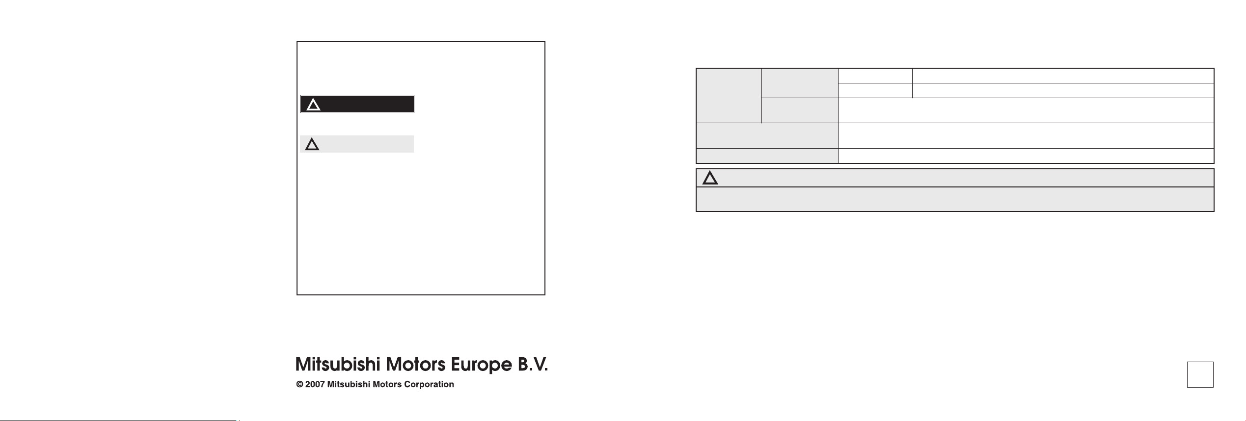
Overview
LHD (Left-hand drive)
Headlamp levelling switch* P. 3-65
Sonar switch* P. 4-78
Active stability control (ASC) OFF
switch* P. 4-65
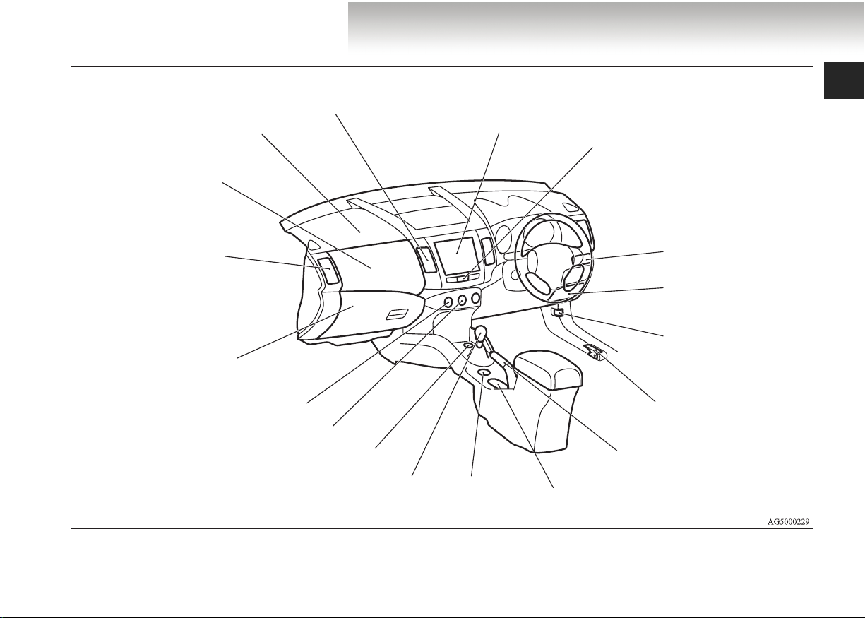
Instruments and Controls
E00100102818
Combination headlamps and dipper switch P. 3-60
Turn-signal lever P. 3-68
Front fog lamp switch* P. 3-69
Instruments P. 3-2
Shift paddles*
P. 4-32, 4-42
Windscreen wiper and washer
switch P. 3-71
Rear window wiper and washer
switch P. 3-77
Cruise control switch* P. 4-68
Steering wheel audio remote control
switches* P. 5-68
Voice recognition switch for hands-free
Bluetooth
®
cellular phone interface*
P. 5 -8 0
Supplemental restraint system (SRS) airbag
(for driver’s seat) P. 2-55, 2-62
Horn switch P. 3-81
Ignition switch P. 4-15
Steering wheel height
adjustment lever P. 4-9
Page 5
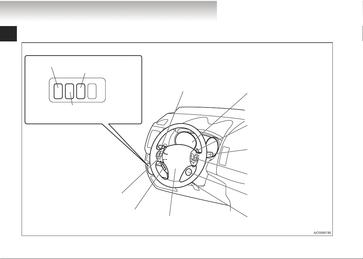
Overview
RHD (Right-hand drive)
Instruments P. 3-2
Shift paddles*
P. 4-32, 4-42
Combination headlamps and
dipper switch P. 3-60
Turn-signal lever P. 3-68
Front fog lamp switch P. 3-69
Steering wheel audio remote
control switches P. 5-68
Voice recognition switch for
hands-free Bluetooth
®
cellular
phone interface P. 5-80
Steering wheel height adjustment
lever P. 4-9
Supplemental restraint system (SRS) airbag (for driver’s seat) P. 2-55, 2-62
Horn switch P. 3-81
Headlamp levelling switch P. 3-65
Sonar switch* P. 4-78
Windscreen wiper and washer
switch P. 3-71
Rear window wiper and washer
switch P. 3-77
Active stability control (ASC) OFF
switch* P. 4-65
Cruise control switch* P. 4-68
Ignition switch P. 4-15
Page 6
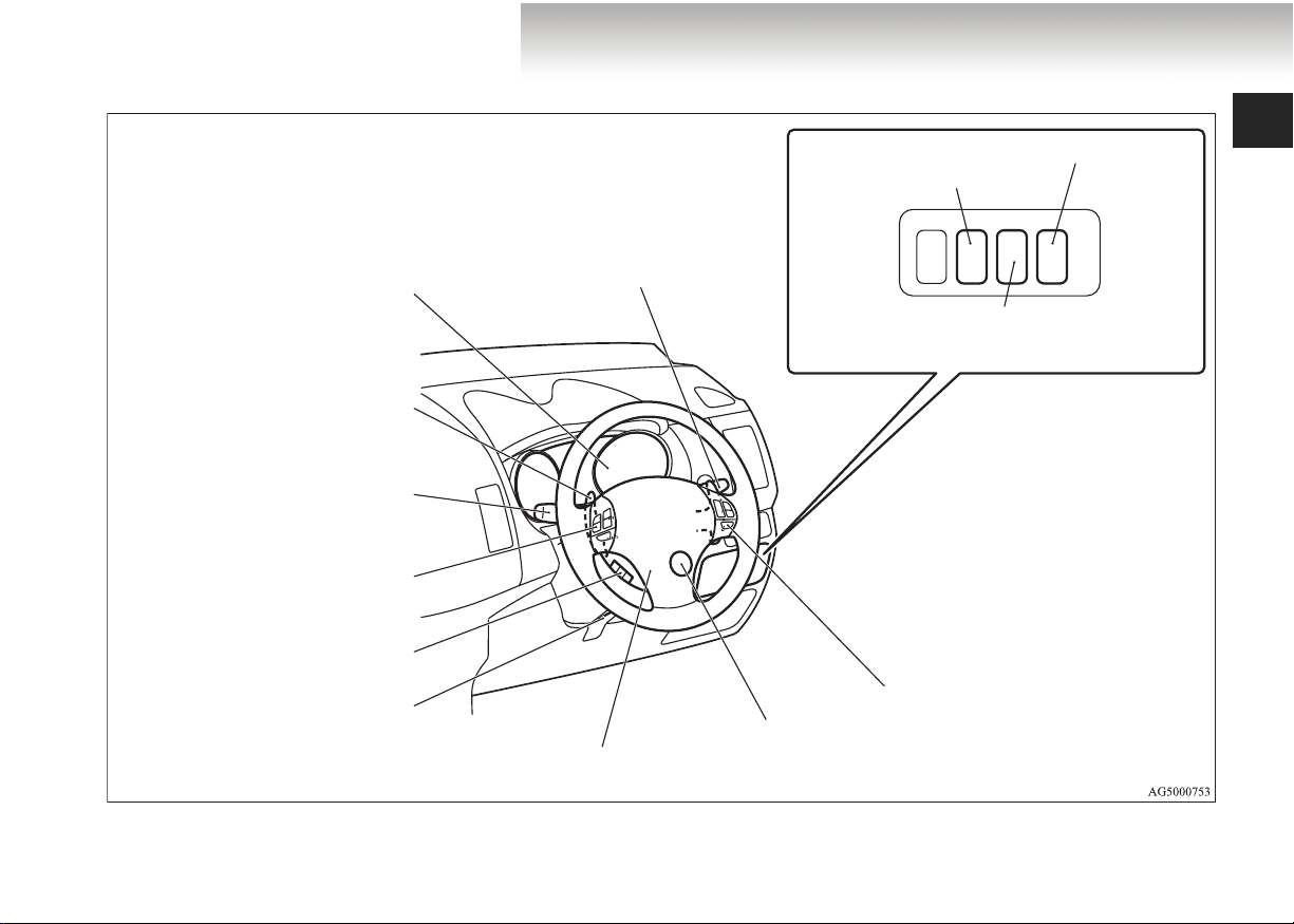
Overview
LHD (Left-hand drive)
HDD navigation & Mitsubishi Multi-Communication System*
Hazard warning flasher switch P. 3-69
Air conditioning P. 5-7
Built-in cup holder P. 5-133
Personal box P. 5-131
Fuse box P. 8-29
Bonnet release lever P. 8-3
Digital clock* P. 5-76
Audio system* P. 5-16, 5-40
Centre ventilators P. 5-2
Supplemental restraint system
(SRS)-airbag (for front passenger’s seat) P. 2-55, 2-62
Upper glove box P. 5-126
Side ventilators P. 5-2
Lower glove box P. 5-128
Front passenger’s airbag
ON-OFF switch P. 2-60
Fuel tank filler door release
lever P. 3
Cup holder P. 5-133
Drive mode selector P. 4-47
Rear window demister switch P. 3-80
Wiper de-icer switch* P. 3-79
Accessory socket P. 5-119
Gearshift or selector lever P. 4-25
Parking brake lever P. 4-6
Page 7
Overview
RHD (Right-hand drive)
Supplemental restraint system
(SRS)-airbag (for front passenger’s seat) P. 2-55, 2-62
Upper glove box P. 5-126
Side ventilators P. 5-2
Lower glove box P. 5-128
Front passenger’s airbag
ON-OFF switch P. 2-60
Fuse box P. 8-29
Rear window demister switch P. 3-80
Wiper de-icer switch* P. 3-79
Air conditioning P. 5-7
Accessory socket P. 5-119
Gearshift or selector lever
P. 4 -2 5
Centre ventilators
P. 5-2
Digital clock* P. 5-76
Audio system* P. 5-16, 5-40
HDD navigation & Mitsubishi Multi-Communication System*
Hazard warning flasher switch P. 3-69
Built-in cup holder P. 5-133
Personal box P. 5-131
Bonnet release lever
P. 8-3
Fuel tank filler door release lever P. 3
Parking brake lever P. 4-6
Drive mode selector
P. 4 -4 7
Cup holder P. 5-133
Page 8
Overview
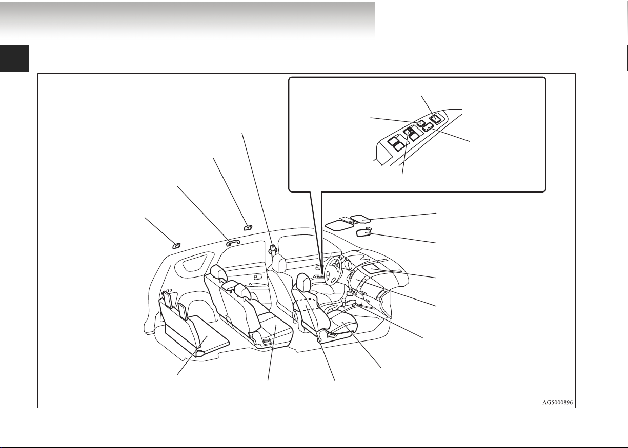
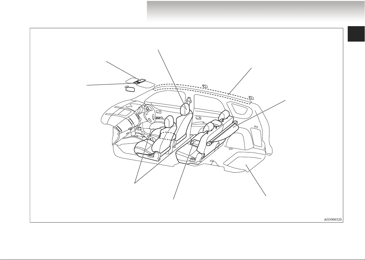
Interior
E00100202082
Outside rear-view mirror switch P. 4-10
Adjustable seat belt anchor P. 2-38
Room lamp (rear) P. 5-121
Assist grip P. 5-139
Coat hook P. 5-139
Luggage room lamp P. 5-121
Underfloor-stowable third seat
(7 persons) P. 2-13
Seat belts P. 2-34
Second seat P. 2-11
Lock switch
P. 1-56
Central door lock switch
P. 1 -4 3
Electric window control switch P. 1-56
Sun visors P. 5-118
Vanity mirror P. 5-119
Card holder P. 5-118
Inside rear-view mirror P.4-9
Upper instrument panel box
P. 5-131
Hands-free Bluetooth® cellular
phone interface system with
voice recognition* P. 5-80
Accessory socket P. 5-119
Front seat P. 2-6
Armrest P. 2-9
Accessory socket P. 5-119
Page 9
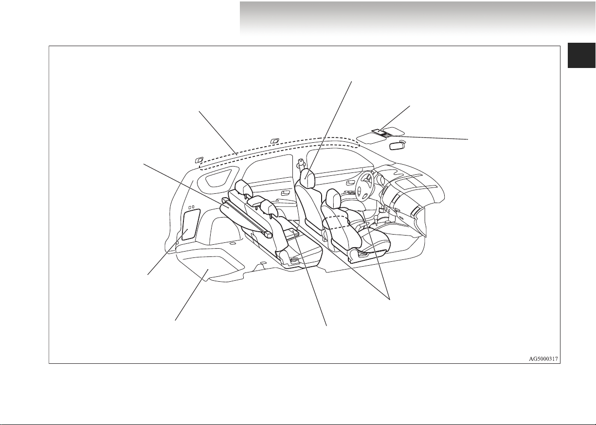
LHD (Left-hand drive)
Overview
Head restraints P. 2-23
SRS curtain airbag* P. 2-55, 2-67
Cargo area cover P. 5-137
Quarter trim box P. 5-132
Luggage floor box (with 5 seat configuration)
P. 5-133
Sunglasses holder P. 5-132
Sunroof switch*
P. 1 -6 1
Map lamp & room
lamp (front) P. 5-121
Bottle holder P. 5-135
Armrest P. 2-12
Cup holder P. 5-134
Page 10
Overview
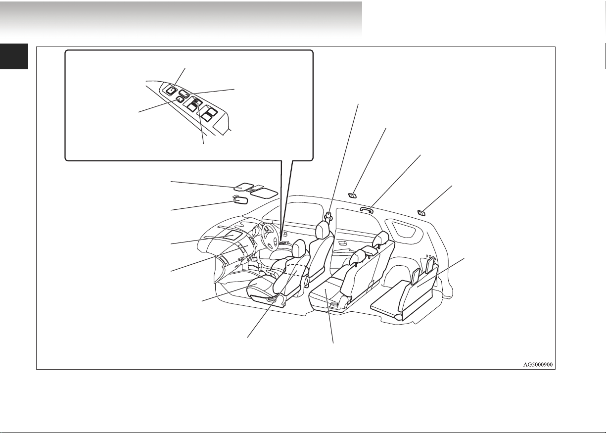
Outside rear-view mirror switch P. 4-10
Lock switch P. 1-56
Electric window control switch P. 1-56
Sun visor P. 5-118
Card holder P. 5-118
Vanity mirror P. 5-119
Inside rear-view mirror
P. 4-9
Upper instrument panel box
P. 5-131
Hands-free Bluetooth® cellular
phone interface system with voice
recognition P. 5-80
Front seat P. 2-6
Central door lock
switch P. 1-43
RHD (Right-hand drive)
Adjustable seat belt anchor P. 2-38
Seat belts P. 2-34
Room lamp (rear) P. 5-121
Assist grip P. 5-139
Coat hook P. 5-139
Luggage room lamp
P. 5-121
Underfloor-stowable
third seat (7 persons)
P. 2-13
Armrest P. 2-9
Accessory socket P. 5-119
Second seat P. 2-11
Page 11
RHD (Right-hand drive)
Overview
Head restraints P. 2-23
Sunglasses holder P. 5-132
Sunroof switch* P. 1-61
Map lamp & room
lamp (front) P. 5-121
Bottle holder P. 5-135
Armrest P. 2-12
Cup holder P. 5-134
SRS curtain airbag* P. 2-55, 2-67
Cargo area cover
P. 5-137
Luggage floor box (with 5 seat
configuration) P. 5-133
Page 12

Overview
Luggage area
E00100400699
Accessory socket P. 5-119
Luggage hook P. 5-140
Luggage hook P. 5-140
Luggage hook P. 5-140
Jack P. 6-14
Tools P. 6-14
Luggage hook P. 5-140
Page 13
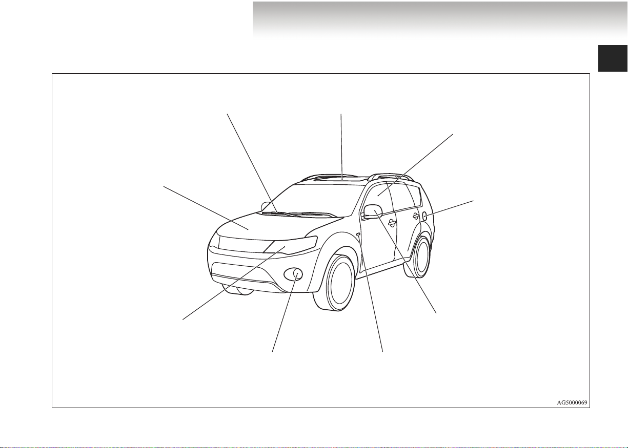
Exterior
Overview
E00100502274
Windscreen wipers P. 3-71
Bonnet P. 8-3
Headlamps P. 3-60, 8-41, 8-43
Position lamps P. 3-60, 8-41, 8-46
Turn-signal lamps/Hazard warning lamps
P. 3-68, 8-41, 8-48
Front fog lamps*
P. 3-69, 8-41, 8-49
Sunroof* P. 1-61
Electric window control P. 1-56
Fuel tank filler P. 3
Outside rear-view mirror P. 4-10
Turn-signal lamps P. 3-68, 8-41, 8-49
Hazard warning lamps P. 3-69
Page 14
Overview
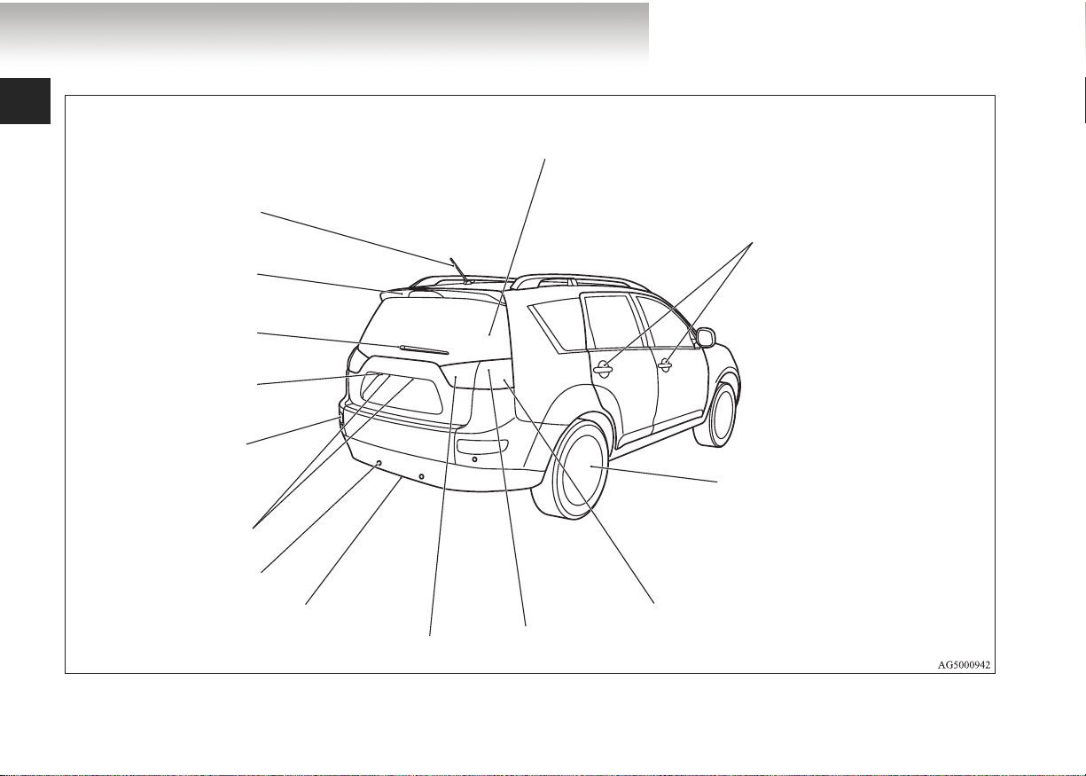
Split tailgate P. 1-49
Antenna P. 5-75
Rear spoiler
Rear window wiper
P. 3 -7 7
Rear view camera
P. 4-82
Rear fog lamp
P. 3-70, 8-41, 8-52
Licence plate lamps
P. 3-60, 8-41, 8-57
Rear parking sensor * P. 4-76
Spare wheel P. 6-19
Reversing lamps P. 3-60, 8-41, 8-56
Keyless entry system P. 1-6
Keyless operation system* P. 1-10
Locking and unlocking the doors P. 1-41
Size of tyres and wheels P. 9-12
Tyre inflation pressures P. 8-18
Changing tyres P. 6-17
Tyre rotation P. 8-20
Tyre chains P. 8-22
Turn-signal lamps/Hazard warning lamps
P. 3-68, 8-41, 8-54
Stop lamps/Tail lamps
P. 3-60, 8-41, 8-54
Page 15

General information
Fuel selection . . . . . . . . . . . . . . . . . . . . . . . . . . . . . . 2
Filling the fuel tank . . . . . . . . . . . . . . . . . . . . . . . . . 3
Installation of accessories . . . . . . . . . . . . . . . . . . . . 6
Modification/alterations to the electrical
or fuel systems . . . . . . . . . . . . . . . . . . . . . . . . . . . 7
Genuine Parts. . . . . . . . . . . . . . . . . . . . . . . . . . . . . . 7
Safety and disposal information for used engine oil 8
Page 16
General information
N
Fuel selection
E00200101375
Petrol-powered vehicles
Unleaded petrol, octane number (EN228)
Recommended
!
CAUTION
● With petrol-powered vehicles, the use of leaded fuel
can result in serious damage to the engine and catalytic converter.
● Diesel-powered vehicles are designed to use only die-
sel fuel that meets the EN 590 standard.
Use of any other type of diesel fuel can adversely
affect the engine.
OTE
● Since petrol-powered vehicles have a knock control system, you can use unleaded petrol 90 RON in emergencies
if unleaded petrol 95 RON or higher is not available.
In such cases, no adjustments of the engine are necessary.
However, with unleaded petrol of 90 RON engine performance will be reduced.
95 RON or higher
Diesel-powered vehicles
Cetane number (EN590)
51 or higher
● Repeatedly driving short distances at very low speeds can
cause deposits in the fuel system and engine, which can
lead to poor starting ability or acceleration. If these problems occur, add a detergent additive to the petrol when
refuelling. The additive will remove the deposits, thereby
returning the engine to a normal condition. Be sure to use
a genuine MITSUBISHI FUEL SYSTEM CLEANER.
Using an unsuitable additive could cause engine malfunction. For details, please contact your MITSUBISHI
MOTORS Authorised Service Point.
2
Page 17

General information
Filling the fuel tank
E00200201321
!
WARNING
● When handling fuel, comply with the safety regula-
tions displayed by garages and filling stations.
● Before removing the fuel cap, be sure to get rid of
your body’s static electricity by touching a metal
part of either the car or the fuel pump. Any static
electricity on your body could create a spark that
will ignite fuel vapour.
● Perform the entire refuelling process (opening the
fuel tank filler door, removing the fuel cap, etc.) by
yourself. Do not allow any other person to come
near the fuel tank filler. Discharge of static electricity from an assisting person might ignite the fuel
vapours, too.
● Do not move away from the fuel tank filler until
refuelling is finished. If you move away and do
something else (for example, cleaning your windscreen) partway through the refuelling process, you
could pick up a fresh charge of static electricity.
● If the tank cap must be replaced, use only a
MITSUBISHI MOTORS original part.
Fuel tank capacity
2WD models: 63 litres
4WD models: 60 litres
Refuelling
1. Before filling your vehicle with fuel, turn off the engine.
2. The fuel tank filler is located on the rear left side of your
vehicle.
Open the fuel tank filler door by pulling the release lever
located on the side of the driver’s seat.
LHD
3
Page 18

General information
RHD
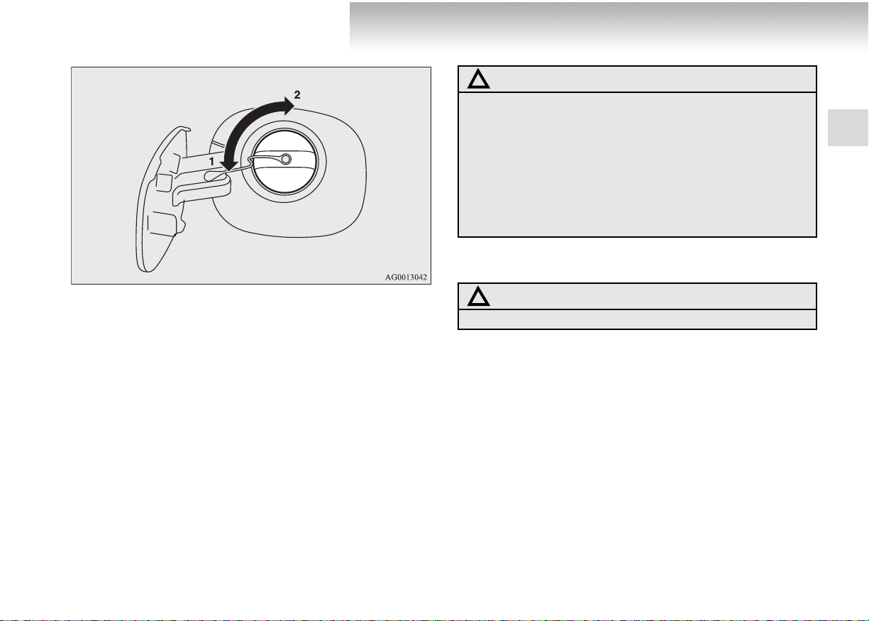
3. Remove the fuel cap.
Open the fuel tank filler neck by slowly turning the cap
anticlockwise.
Except for 2200 models
1- Remove
2- Close
4
Page 19
General information
For 2200 models
1- Remove
2- Close
!
CAUTION
● The fuel cap does not turn more than 90 degrees.
Turning it further by force could damage the fuel
cap.
● Since the fuel system may be under pressure,
remove the fuel cap slowly. This relieves any pressure or vacuum that might have built up in the fuel
tank. If you hear a hissing sound from the cap, wait
until it stops before removing the cap. Otherwise,
fuel may spray out and injure you or others.
4. Insert the filler gun into the tank port as far as it will go.
!
CAUTION
● Do not tilt the filler gun.
5. After the second automatic stop, do not fill with fuel anymore.
6. Reattach the fuel cap.
[Except for 2200 models]
To close, turn the tank filler cap slowly clockwise until
you hear clicking sounds and then gently push the fuel
tank filler door shut.
[For 2200 models]
Fit the fuel cap with the cap handle sideways and turn it
clockwise.
5
Page 20

General information
Installation of accessories
E00200300598
We recommend you to consult your MITSUBISHI MOTORS
Authorised Service Point.
● The installation of accessories, optional components, etc.,
should only be carried out within the limits prescribed by
law in your country, and in accordance with the guidelines
and warnings contained within the documents accompanying this vehicle.
● Installing electric components incorrectly could lead to a
fire. See the “Modification/alterations to the electrical or
fuel systems” section within this owner’s manual
● Using a cellular phone or radio set inside the vehicle without an external antenna may cause electrical system interference, which could lead to unsafe vehicle operation.
● Tyres and wheels which do not meet specifications must
not be used.
Refer to the “Specifications” section for information
regarding wheel and tyre sizes.
Important points!
Due to large number of accessory and replacement parts of different manufactures available in the market, it is not possible,
not only for MITSUBISHI MOTORS, but also a MITSUBISHI
MOTORS Authorised Service Point, to check whether the
attachment or installation of such parts affects the overall
safety of your MITSUBISHI-vehicle.
Even when such parts are officially authorised, for example by
a “general operators permit” (an appraisal for the part) or
through the execution of the part in an officially approved manner of construction, or when a single operation permit following the attachment or installation of such parts, it cannot be
deduced from that alone, that the driving safety of your vehicles has not been affected.
Consider also that there basically exists no liability on the part
of the appraiser or the official. Maximum safety can only be
ensured with parts recommended, sold and fitted or installed by
a MITSUBISHI MOTORS authorised Service Point
(MITSUBISHI MOTORS genuine replacement parts and
MITSUBISHI MOTORS accessories). The same also pertains
to modifications of MITSUBISHI vehicles with respect to the
production specifications. For safety reasons, do not attempt
any modifications other than those that follow the recommendations of a MITSUBISHI MOTORS authorised Service Point.
6
Page 21

General information
Modification/alterations to the electrical or
fuel systems
E00200400368
MITSUBISHI MOTORS CORPORATION has always manufactured safe, high quality vehicles. In order to maintain this
safety and quality, it is important that any accessory that is to
be fitted, or any modifications carried out which involve the
electrical or fuel systems, should be carried out in accordance
with MITSUBISHI guidelines.
!
CAUTION
● If the wires interfere with the vehicle body or
improper installation methods are used (protective
fuses not included, etc.), electronic devices may be
adversely affected, resulting in a fire or other accident.
Genuine Parts
E00200500499
MITSUBISHI MOTORS has gone to great lengths to bring you
a superbly crafted automobile offering the highest quality and
dependability.
Use MITSUBISHI MOTORS Genuine Parts, designed and
manufactured to maintain your MITSUBISHI MOTORS automobile at top performance. MITSUBISHI MOTORS Genuine
Parts are identified by this mark and are available at all
MITSUBISHI MOTORS Authorised Service Points.
7
Page 22
General information
Safety and disposal information for used
engine oil
E00200600155
!
WARNING
● Prolonged and repeated contact may cause serious
skin disorders, including dermatitis and cancer.
● Avoid contact with the skin as far as possible and
wash thoroughly after any contact.
● Keep used engine oils out of reach of children.
Protect the environment
It is illegal to pollute drains, water courses and soil. Use
authorised waste collection facilities, including civic amenity
sites and garages providing facilities for disposal of used oil
and used oil filters. If in doubt, contact your local authority for
advice on disposal.
8
Page 23

Locking and unlocking
Keys . . . . . . . . . . . . . . . . . . . . . . . . . . . . . . . . . . . .1- 2
Electronic immobiliser
(Anti-theft starting system). . . . . . . . . . . . . . . . .1- 4
Keyless entry system* . . . . . . . . . . . . . . . . . . . . . .1- 6
Keyless operation system (KOS)*. . . . . . . . . . . . .1- 10
Doors . . . . . . . . . . . . . . . . . . . . . . . . . . . . . . . . . . .1- 41
Central door locking system . . . . . . . . . . . . . . . . .1- 43
Dead Lock System*. . . . . . . . . . . . . . . . . . . . . . . .1- 45
“Child-protection” rear doors . . . . . . . . . . . . . . . .1- 48
Split tailgate . . . . . . . . . . . . . . . . . . . . . . . . . . . . . .1- 49
Tailgate emergency release lever . . . . . . . . . . . . . .1- 54
Electric window control. . . . . . . . . . . . . . . . . . . . .1- 56
Sunroof*. . . . . . . . . . . . . . . . . . . . . . . . . . . . . . . . .1- 61
1
Page 24
Locking and unlocking
Type 1, Type 2, Type 3
The keys fit all locks.
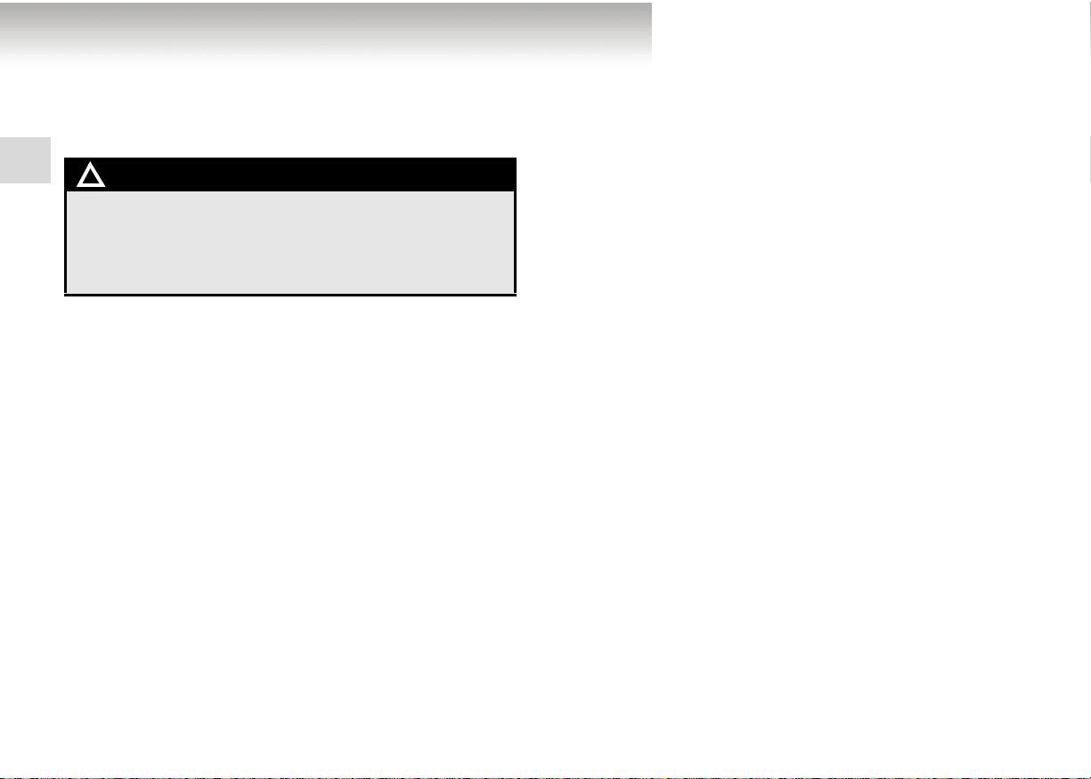
Type 1
1
1- Electronic immobiliser key
2- Key number tag
Keys
E00300101217
Type 2
1- Keyless entry key
(with electronic immobiliser)
2- Key number tag
1-2
Page 25
Locking and unlocking
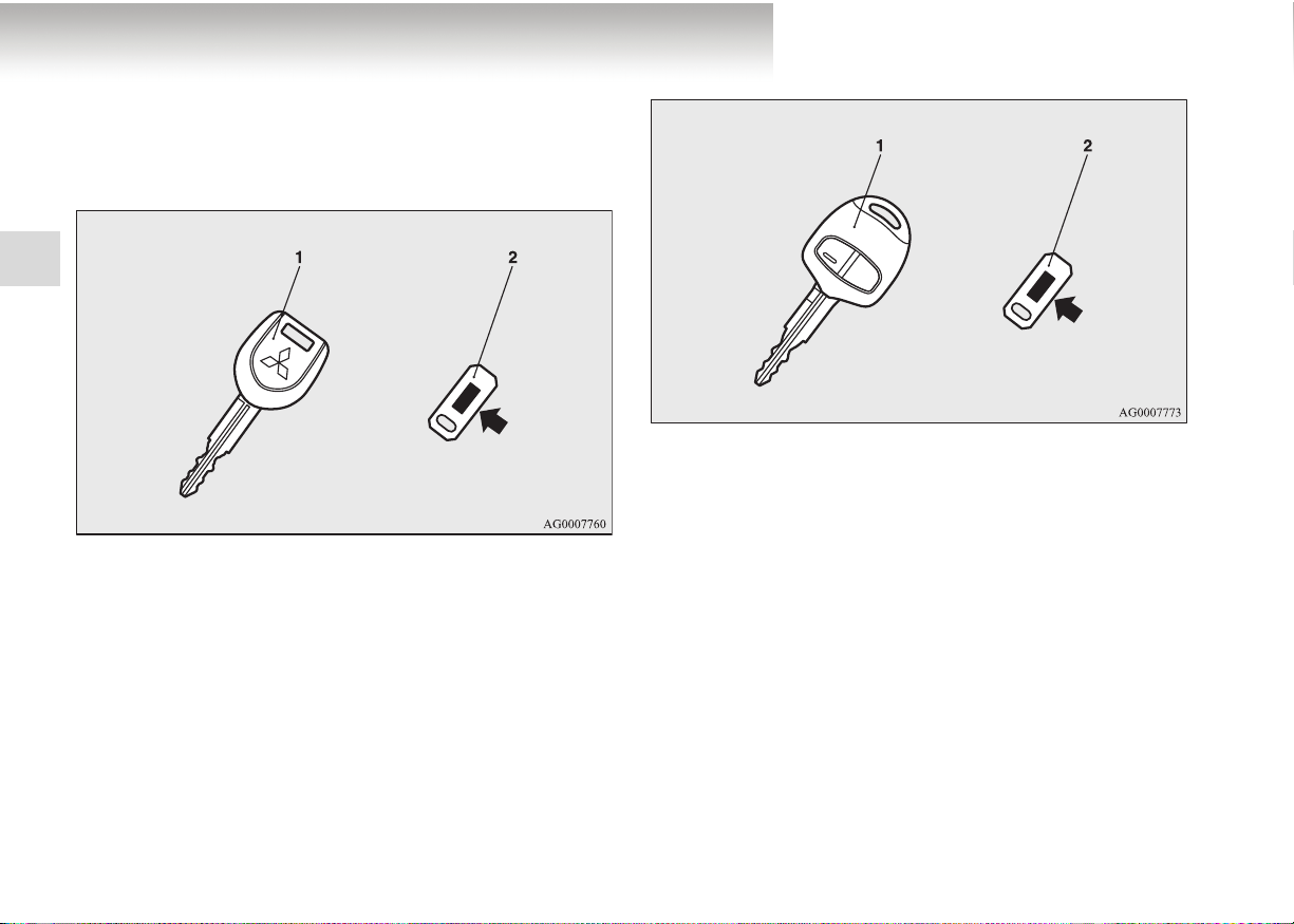
Type 3
1- Keyless entry key
(with electronic immobiliser)
2- Key number tag
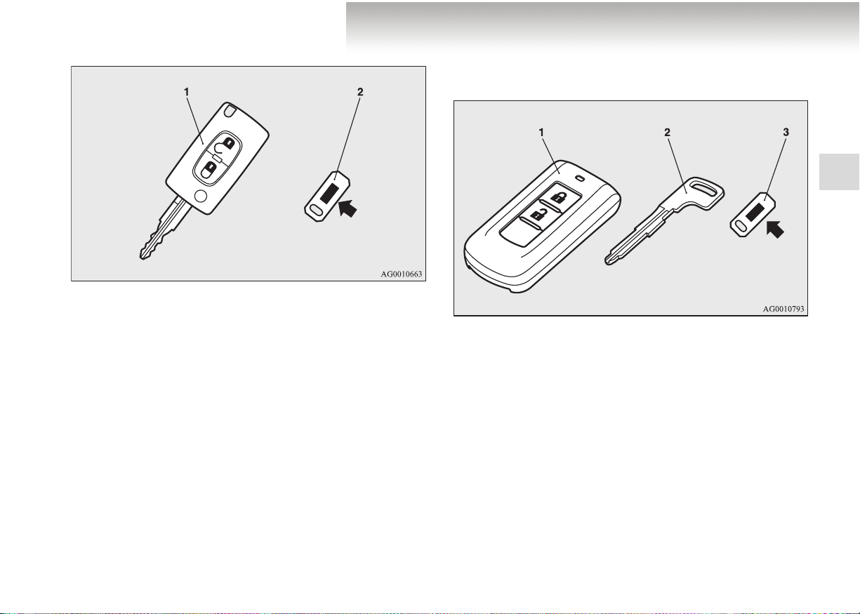
Type 4
The emergency key fits all locks.
Type 4
1
1- Keyless operation key
(with electronic immobiliser and lock remote control but-
tons)
2- Emergency key
3- Key number tag
1-3
Page 26

Locking and unlocking
N
OTE
● The key number is stamped on the tag as indicated in the
illustration.
Make a record of the key number and store the key and
key number tag in separate places so that you can order a
key in case the original keys are lost.
● The key is a precision electronic part with a built-in signal
1
transmitter. Please observe the following to prevent malfunctions.
• Do not leave this chip key in places exposed to direct
sunlight, for example on the dashboard.
• Do not disassemble or modify it.
• Do not excessively bend the key or subject it to strong
impact.
• Do not expose it to water.
• Keep it away from magnetic key holders.
• Keep it away from audio systems, personal computers,
TVs, and other equipment that generates a magnetic
field.
• Do not clean with ultrasonic cleaners or similar equipment.
• Do not leave the key in places exposed to high temperatures or high humidity.
● The engine is designed so that it will not start if the ID
code registered in the immobiliser computer and the key’s
ID code do not match. Refer to the section entitled “Electronic immobiliser” for details and key usage.
[For vehicles equipped with keyless operation key]
For information on operations for vehicles equipped with keyless operation system, refer to “keyless operation system: Electronic immobiliser (Anti-theft starting system on page 1-18.
[For vehicles equipped with keyless operation key]
The electronic immobiliser is designed to significantly reduce
the possibility of vehicle theft. The purpose of the system is to
immobilise the vehicle if starting is attempted with an invalid
ignition key. Starting the engine is only possible with a key
“registered” in the immobiliser system.
Electronic immobiliser
(Anti-theft starting system)
E00300201146
1-4
Page 27
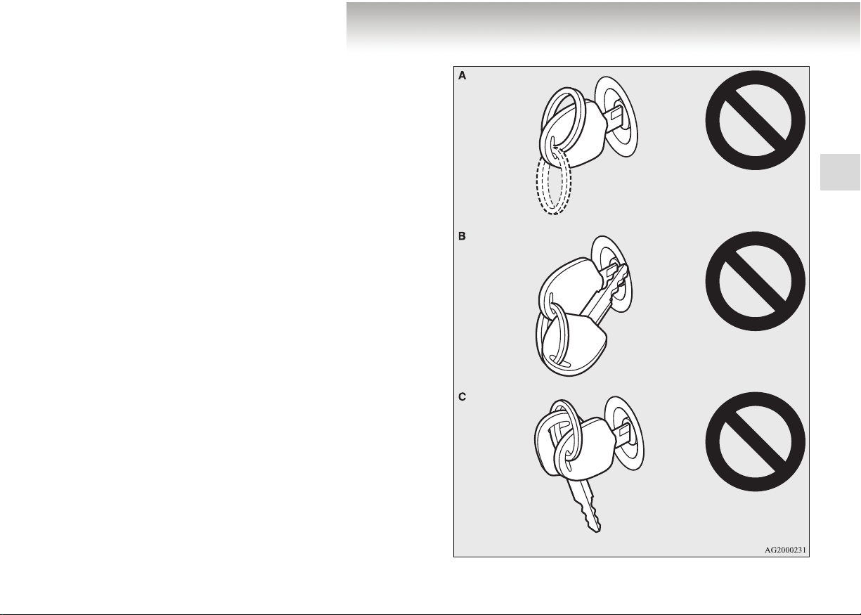
N
OTE
● In the following cases, the vehicle may not be able to
receive the registered ID code from the key and the engine
may not start.
• When the key comes into contact with a key ring or
another metallic or magnetic object (Type A)
• When the key grip comes into contact with the metal of
another key
(Type B)
• When the key contacts or is close to other immobilising
keys (including keys of other vehicles) (Type C)
In these cases remove the object or additional key from
the vehicle key. Then try to restart the engine. If the
engine does not start, contact a MITSUBISHI MOTORS
Authorised Service Point.
Locking and unlocking
1
1-5
Page 28
Locking and unlocking
● Two keys are provided.
If you lose one of them, order a key from your MITSUBISHI MOTORS Authorised Service Point as soon as possible. To obtain a key, take your vehicle and any remaining
key to a MITSUBISHI MOTORS Authorised Service
Point. All the keys have to be re-registered in the immobiliser computer unit. The immobiliser can register up to 8
1
different keys for use.
!
CAUTION
● Do not modify or add parts to the immobiliser sys-
tem. Doing so could cause the immobiliser to malfunction.
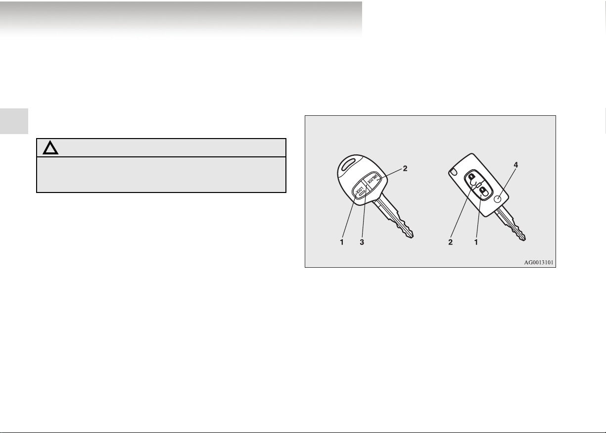
Press the corresponding remote control switch on the key and
all doors as well as the tailgate will lock or unlock respectively.
These switches can also operate the door mirrors and electric
windows.
Type 1 Type 2
1- LOCK switch
2- UNLOCK switch
3- Indicator lamp
4- Release button
Keyless entry system*
E00300301411
1-6
Page 29

Locking and unlocking
N
N
To l oc k
Press the LOCK switch (1) and all doors and the tailgate will
be locked. The turn-signal lamps will blink once when the
doors are locked.
OTE
● On a vehicle equipped with a Dead Lock System, pressing
the LOCK switch (1) twice in succession will set the Dead
Lock System. (Refer to “Setting the system” on page
1-45.)
To unlock
Press the UNLOCK switch (2) and all doors and the tailgate
will be unlocked. If the doors are unlocked when the room
lamp switch is in the middle position, the room lamp will illuminate for approximately 15 seconds and the turn-signal lamps
will blink twice.
OTE
● The indicator lamp (3) turns on each time a switch is
pressed. (Type 1 only)
● If you have pressed the UNLOCK switch (2), but do not
open any of the doors or the tailgate within approximately
30 seconds, relocking will automatically occur. On vehicles with the Mitsubishi Multi-Communication System
(MMCS), this function can be customised via the display.
Refer to the separate owner’s manual for details.
1
1-7
Page 30
Locking and unlocking
● It is possible to modify functions as follows:
For further information, please contact your MITSUBISHI MOTORS Authorised Service Point. On vehicles
with the Mitsubishi Multi-Communication System
(MMCS), this function can be customised via the display.
Refer to the separate owner’s manual for details.
• The time until automatic relocking can be changed.
1
• The confirmation function (flashing of the turn-signal
lamps) can be set to operate only when the doors and
tailgate are locked or only when the doors and tailgate
are unlocked.
• The confirmation function (this indicates the locking or
unlocking of the doors and tailgate with a flash of the
turn-signal lamps) can be deactivated.
• It is possible to change the number of times the turn-signal lamps are flashed by the confirmation function.
Operation of the Dead Lock System
On a vehicle equipped with a Dead Lock System, it is possible
to set the Dead Lock System using the remote controller.
(Refer to “Dead Lock System” on page 1-45.)
Linked operation of electric windows
To c l os e
You can close the windows within 30 seconds after locking the
doors with the LOCK switch (1) by pressing the switch a second time for at least 1 second.
To stop the windows part-way, press the LOCK switch again or
press the UNLOCK switch (2).
!
WARNING
● Ensure that no one is near the door windows before
closing them by pressing the remote control switch
on the key. Hands or fingers could be caught in a
closing window and injured.
1-8
Page 31

Locking and unlocking
N
Linked operation of outside rear-view mirrors
To retract
You can fold in the outside rear-view mirrors within 30 seconds
after locking the doors and tailgate with the LOCK switch (1)
by pressing the switch twice in rapid succession.
To f o ld out
You can fold out the outside rear-view mirrors within 30 seconds after unlocking the doors and tailgate with the UNLOCK
switch (2) by pressing the switch twice in rapid succession.
Operation of the key (Type 2 only)
To f o ld
Fold the key into the casing while pressing the Release button
(4).
To f o ld out
Press the Release button (4).
OTE
● The function of the remote control switches can be modified as stated below. Please consult your MITSUBISHI
MOTORS Authorised Service Point.
• Disable the key-linked “Close” function for the electric
windows.
• Add a key-linked ’Open’ function for electric windows.
• Link the folding-in and folding-out of the outside rearview mirrors to door locking and unlocking.
• Disable all operations.
● The keyless entry system does not operate under the following conditions:
• The key is left in the key cylinder.
• The door or tailgate is open.
● The remote control switches will function from within
about 4 m of the vehicle. However, the operating range of
the remote control switch may vary if the vehicle is
located near a TV transmitting tower, power station or
radio broadcasting station.
● If either of the following problems occurs, the battery may
be discharged. Have the battery replaced by a
MITSUBISHI MOTORS Authorised Service Point.
• Although the remote control switch is operated within
the correct distance from the vehicle, neither the doors
nor tailgate will lock or unlock.
• The indicator lamp (3) is dim or does not come on.
(Type 1 only)
● In case of loss or damage of your key with remote control
switches please contact your MITSUBISHI MOTORS
Authorised Service Point for a replacement.
● If you wish to have an additional key with remote control,
pl. contact your MITSUBISHI MOTORS Authorised
Service Point.
A maximum of 8 keys with remote control can be set for
your vehicle.
1
1-9
Page 32

Locking and unlocking
Keyless operation system (KOS)
On vehicles with keyless operation system or KOS you can
lock and unlock the doors as well as the tailgate and start the
engine simply by carrying the KOS key or electronic key with
you.
In addition the KOS key also features lock remote control
1
switches just like the normal key with remote control switches
of the keyless entry system.
Refer to “Keyless operation system (KOS): Keyless entry system” on page 1-38.
The driver should always carry the KOS key (keyless operation
key). This electronic key is necessary for locking and unlocking the doors and tailgate, starting the engine and operating the
vehicle. Therefore, before locking and leaving the vehicle,
make sure that you have the KOS key (keyless operation key)
on you.
!
WARNING
● People with implantable cardiac pacemakers or
implantable cardiovascular-defibrillators should not
go near the exterior transmitters (A) or the interior
transmitters (B) of the KOS system. The radio
waves used by the keyless operation system could
adversely affect implanted cardiac pacemakers or
cardiovascular defibrillators.
*
E00305600106
1-10
Page 33

Locking and unlocking
N
!
WARNING
● When using electromedical devices other than
implanted cardiac pacemakers or implantable cardiovascular-defibrillators, contact your doctor or
electromedical device manufacturer ahead of time to
determine the affects of radio waves on such devices.
In general, the function of electromedical devices
can be affected by radio waves.
● The keyless operation system (KOS) can be disa-
bled. For further information, please contact your
MITSUBISHI MOTORS Authorised Service Point.
You can limit the possible operations of the keyless operation system as listed below. (The functions of the KOS
system can be reduced to those of a conventional keyless
entry system). Please consult your MITSUBISHI
MOTORS Authorised Service Point. On vehicles with the
Mitsubishi Multi-Communication System (MMCS), this
function can be customised via the display. Refer to the
separate owner’s manual for details.
• You can limit operations to the locking and unlocking of
doors and the tailgate.
• You can limit operations to starting the engine.
When functions of the keyless operation system (KOS)
are modified, the transmitters operate as follows.
• Only locking and unlocking doors: exterior and interior
transmitters
• Only starting the engine: interior transmitter
OTE
● The KOS key employs ultra-weak electromagnetic waves.
In the following cases, the keyless operation system may
not operate properly or become unstable.
• In the vicinity of equipment that emits strong radio
waves, such as: TV transmitting towers, power stations,
radio broadcasting stations or airports.
• If the KOS key is carried close to a communications
device such as a cell phone or radio set, or kept close to
an electronic device such as a personal computer.
• If the KOS key is touching or covered by a metal object.
• If a keyless entry system is being used nearby.
• When the KOS key battery is worn out.
• When the KOS key is placed in an area with strong radio
waves or noise.
In such cases, use the emergency key.
Refer to “Operation without keyless operation function”
on page 1-38.
• Since the KOS key has to prompting signals in order to
initiate communication with the transmitters in the vehicle, the battery continually wears down regardless of the
KOS key’s use. The battery life is 1 to 3 years, depending on usage conditions. When the battery wears out,
have it replaced at your MITSUBISHI MOTORS
Authorised Service Point.
● Since the KOS key continually receives signals, strong
radio wave reception could affect battery wear. Do not
leave the key near a TV, PC, or other electronic device.
1
1-11
Page 34

Locking and unlocking
N
Operating range of the KOS system
(keyless operation system)
When carrying the KOS key you need to enter the operating
range of the keyless operation system in order to become able
to operate a door or tailgate switch or handle provided the ID
code of your key has been successfully verified by the system.
1
You can only lock or unlock the doors and tailgate and start the
engine if the ID codes of your KOS key and the vehicle match.
OTE
● If the KOS key battery is wearing out or there are strong
electromagnetic waves or noise present, the operating
range may become smaller and operation may become
unstable.
E00305700093
Operating range for locking and unlocking of doors
and tailgate
E00306200095
The operating range extends about 70 cm from the driver’s
door handle, front passenger’s door handle, and tailgate handle.
*: Forward direction
Operating range
:
1-12
Page 35

Locking and unlocking
N
N
OTE
● Locking and unlocking are only possible when the door or
tailgate is operated while the KOS key is being detected.
● Operation may not be possible if you are too close to the
front door, door window, or tailgate.
● Even though the KOS key is within 70 cm of the driver’s
door handle, front passenger’s door handle, or tailgate
handle, the system may not operate if the key is near the
ground or positioned too high.
● If the KOS key is within the system’s operating range,
even someone who is not carrying the KOS key can lock
and unlock the doors and tailgate by operating the driver’s
door, front passenger’s door switch or tailgate handle.
Operating range for starting the engine
E00306300012
The operating range is the interior of the vehicle.
*: Forward direction
Operating range
:
OTE
● Even if it is within the operating range, if the keyless
operation key is in a small item holder such as the glove
box, on top of the instrument panel, door pocket or in the
luggage area, it may be impossible to start the engine.
● If you are too close to the door or door window, the engine
may start even though the keyless operation key is outside
the vehicle.
1
1-13
Page 36

Locking and unlocking
Operation with keyless operation function
Locking the doors and tailgate
When you are carrying the KOS key and press the “LOCK”
switch (A) on the driver’s door, front passenger’s door, or tailgate within the system’s operating range, the doors and the tailgate will lock.
1
Also refer to “Locking and unlocking: Doors, Central door
locks, tailgate” on pages 1-41, 1-43, 1-49.
E00305800094
Driver’s door and front passenger’s door switches
Tailgate switch
1-14
Page 37

Locking and unlocking
N
OTE
● The keyless operation function does not work under the
following conditions:
• The KOS key is inside the vehicle.
• A door or the tailgate is open or ajar.
• The ignition switch is not in the “LOCK” position.
• The emergency key is in the ignition switch.
● To check whether the vehicle is locked, pull on the door or
tailgate handle within about 3 seconds after locking the
vehicle. If you wait more than 3 seconds and pull on one
of the handles, the doors and tailgate will unlock.
The time allowed for checking whether the vehicle is
locked can be adjusted. For further information, please
contact your MITSUBISHI MOTORS Authorised Service
Point. On vehicles with the Mitsubishi Multi-Communication System (MMCS), this function can be customised
via the display. Refer to the separate owner’s manual for
details.
Unlocking the doors and tailgate
When you are carrying the KOS key and grip the handle of the
driver’s door or front passenger’s door or pull on the tailgate
handle within the system’s operating range, the doors and the
tailgate will unlock.
Also refer to “Locking and unlocking: Doors, Central door
locks, tailgate” on pages 1-41, 1-43, 1-49.
1
Front door handle Tailgate handle
1-15
Page 38

Locking and unlocking
N
OTE
● The keyless operation function does not work under the
following conditions:
• The KOS key is inside the vehicle.
• A door or the tailgate is open or ajar.
• The ignition switch is not in the “LOCK” position.
• The emergency key is in the ignition switch.
1
● To allow for checking whether the doors and tailgate are
locked, you cannot unlock them for 3 seconds after locking them.
● The time allowed for checking whether the vehicle is
locked can be adjusted. For further information, please
contact your MITSUBISHI MOTORS Authorised Service
Point. On vehicles with the Mitsubishi Multi-Communication System (MMCS), this function can be customised
via the display. Refer to the separate owner’s manual for
details.
● To unlock, grip the sensor (B) on the rear of a door handle
firmly, check that the doors and tailgate unlock, and then
pull the handle (A). Unlocking may be delayed or prevented under the following conditions:
• You do not properly touch the sensor on the rear of the
handle.
• You touch the sensor on the rear of the handle with
gloves such as leather gloves or ski gloves.
• You are also carrying objects such as KOS key for
another vehicle, a communications device that emits
electromagnetic waves, or an electronic device.
1-16
Page 39

Locking and unlocking
N
N
OTE
● If you pull on the door handle too quickly, it may not
unlock. In this case, grip the handle again, check that the
doors and tailgate have been unlocked, and then pull on
the handle.
● If the door handle is exposed to a large quantity of water,
for example during strong rainfall or in a car wash while
the KOS key is within the operating range of the exterior
transmitter, the keyless operation system may be triggered
and the vehicle will be unlocked. If this happens, the vehicle is automatically locked again after about 30 seconds.
On vehicles with the Mitsubishi Multi-Communication
System (MMCS), this function can be customised via the
display. Refer to the separate owner’s manual for details.
Confirmation function for locking and unlocking
The system operation can be confirmed as shown below. However, the room lamp will only illuminate if the room lamp
switch is in the middle position.
When locking: The turn-signal lamps blink once.
When unlocking: The room lamp illuminates for about 15 sec-
onds and the turn-signal lamps blink twice.
OTE
● This function can be modified as stated below. For further
information, please contact your MITSUBISHI MOTORS
Authorised Service Point.
• Enable the confirmation function (flashing of the turnsignal lamps) only when the vehicle is locked or
unlocked.
• Disable the operation confirmation function (flashing of
turn-signal lamps).
• Change the number of flashes (flashing of turn-signal
lamps) for the operation confirmation function.
1
1-17
Page 40

Locking and unlocking
N
N
Retracting the outside rear-view mirrors
You can fold in the outside rear-view mirrors within 30 seconds
after locking the doors and tailgate with the LOCK switch by
pressing the switch twice in rapid succession.
Closing the door windows
You can close the windows within 30 seconds after locking the
doors with the LOCK switch by pressing the switch a second
1
time for at least 1 second.
OTE
● The switch operations for the door and tailgate can be
changed as follows. For further information, please contact your MITSUBISHI MOTORS Authorised Service
Point.
• Disable the key-linked “Close” function for the electric
windows.
• Link the outside rear-view mirror retraction to door
locking.
• Disable all operations.
Electronic immobiliser
(Anti-theft starting system)
E00306400101
The electronic immobiliser is designed to significantly reduce
the possibility of vehicle theft. The purpose of the system is to
immobilise the vehicle if starting is attempted with an invalid
ignition key. Starting the engine is only possible with a key
“registered” in the immobiliser system.
All of the keys provided with your new vehicle have been programmed into the vehicle’s electronics. Refer to “Keyless operation system : Ignition switch” on page1-19,1-30.
OTE
● If you lose one of the KOS keys, order a key from your
MITSUBISHI MOTORS Authorised Service Point as
soon as possible.
To obtain a key, take your vehicle and any remaining key
to a MITSUBISHI MOTORS Authorised Service Point.
All the keys have to be re-registered in the immobiliser
computer unit. The immobiliser can register up to 4 different keys.
1-18
Page 41

Locking and unlocking
N
Ignition switch
E00306500102
In order to prevent theft, the engine will not start unless a preregistered keyless operation key is used. (Engine immobiliser
function)
Provided you are carrying the KOS key, you can start the
engine by turning the ignition switch.
Also refer to “Starting and driving: Starting the engine” on
page 4-20.
LOCK (PUSH OFF)
The position where the steering wheel is locked.
LOCK (PUSH ON)
When the ID code verification inside the vehicle produces a
match, the steering wheel lock is released and the ignition
switch can be turned.
ACC
The engine is stopped, but the audio system and other electric
devices can be operated.
ON
The engine is running and all of the vehicle’s electrical devices
can be operated.
START
The starter motor operates. Once the engine starts, let go of the
key. The key will automatically return to the “ON” position.
OTE
● Your vehicle is equipped with an electronic immobiliser.
To start the engine, the ID code which the transponder
inside the key sends must match the one registered to the
immobiliser computer.
(Refer to “Electronic immobiliser (Anti-theft starting system)” on page 1-18.)
1
1-19
Page 42

Locking and unlocking
N
N
When turning from “LOCK” (PUSH OFF) to “ACC”
Push the ignition switch and then turn it slowly.
1
A- Steering wheel locked
B- Steering wheel released
OTE
● If the ignition switch does not turn from “LOCK” (PUSH
OFF) to “ACC”, press the ignition switch again, lightly
move the steering wheel left and right, and then turn the
ignition switch.
● The ignition switch cannot be turned if the keyless operation key is not in the vehicle.
Refer to “Operating range for starting the engine” on page
1-13.
E00306600015
When turning from “ACC” to “LOCK”
E00306700032
[Vehicles with M/T]
Put the gearshift lever into the “N” (Neutral) position, and
slowly turn the ignition switch to the “LOCK” position while
pressing it.
[Vehicles with A/T or CVT]
First, set the selector lever to the “P” (PARK) position, and
then slowly turn the ignition switch to the “LOCK” position
while pressing it.
OTE
● On vehicles with A/T or CVT, the ignition switch cannot
be turned to the “LOCK” position unless the selector lever
is in the “P” (PARK) position.
1-20
Page 43

Locking and unlocking
!
CAUTION
● Do not turn the ignition switch to “LOCK” position
while driving. The steering wheel will lock, causing
loss of control.
● If the engine is stopped while driving, the brake ser-
vomechanism will cease to function and braking
efficiency will deteriorate. Furthermore, the power
steering system will not function and it will require
greater manual effort to operate the steering.
● Do not leave the ignition switch in the “ON” position
for a long time when the engine is not running as
this will cause discharge of the battery.
● Do not turn the ignition switch to the “START”
position when the engine is running as doing so
could damage the starter motor.
Warning activation
E00305900109
In order to prevent vehicle theft or an accidental operation of
the keyless operation system, a buzzer and messages on the
multi-information display are used to alert the driver.
If a warning is triggered, always check the vehicle and the
KOS key. Warning messages will also be displayed if there is a
fault in the keyless operation system (KOS).
1
1-21
Page 44

Locking and unlocking
If any of the following warnings are activated, please contact a
MITSUBISHI MOTORS Authorised Service Point.
There is a fault in the keyless operation system.
The battery of the KOS key has worn out.
1
In the following cases, a warning is activated, but it can be cancelled if the correct actions are followed.
● The ID codes of KOS key and vehicle do not match.
You could be carrying another KOS key with a
different code, or the KOS key could be outside
the operating range.
Refer to “KOS key location monitoring system”
on page 1-22.
● Even though you press a door or tailgate “LOCK” switch,
the doors and tailgate will not lock.
Refer to “Key lock-in prevention system” on page
1-23.
Refer to “Door ajar prevention system” on page
1-24.
Refer to “Ignition switch reminder system” on
page 1-24.
KOS key location monitoring system
E00308000042
If you open any of the doors and take the KOS key out of the
vehicle while the ignition switch is in an other position than
“LOCK” (PUSH OFF) , the KOS key and vehicle ID codes
cannot be matched. This will trigger the warning message
“CONFIRM KEY LOCATION” on display and the buzzer will
sound four times.
1-22
Page 45

Locking and unlocking
N
OTE
● If remove the KOS key from the vehicle through a window
without opening a door, the KOS key location monitoring
system will not respond.
● It is possible to change the settings of the KOS key location
monitoring system so that it will respond if you remove the
KOS key from the vehicle through a window without
opening a door. For further information, please contact
your MITSUBISHI MOTORS Authorised Service Point.
● Even though the KOS key is within the engine start oper-
ating range, the keyless operation key and vehicle ID codes
sometimes cannot be matched due to the environment or
electromagnetic conditions. In this case the warning may
be activated.
Key lock-in prevention system
E00308100030
If you close all the doors and the tailgate with the ignition
switch is in the “LOCK” (PUSH OFF) position, but leave the
KOS key in the vehicle, any attempt to lock doors and tailgate
by pressing one of the “LOCK” switches will trigger the warning message “CONFIRM KEY LOCATION” on the display
and the buzzer will sound for about 3 seconds. Under these circumstances locking of doors and tailgate will be impossible.
1
1-23
Page 46

Locking and unlocking
Door ajar prevention system
If you try to lock the doors and tailgate by pressing one of the
“LOCK” switches while one of the doors or the tailgate is not
completely closed, the warning message “CHECK DOORS” is
displayed and the buzzer will sound for about 3 seconds. Under
these circumstances locking of doors and tailgate will be
impossible even with the ignition switch turned to “LOCK”
1
(PUSH OFF).
E00308200031
Ignition switch reminder system
E00308300032
If you close all doors and the tailgate with the ignition switch
in any position other than “LOCK” (PUSH OFF), any attempt
to lock doors and tailgate by pressing one of the “LOCK”
switches will trigger the warning message “STEERING
WHEEL LOCK” on the display and the buzzer will sound for
about 3 seconds. Under these circumstances locking of doors
and tailgate will be impossible.
1-24
Page 47

Locking and unlocking
Steering wheel lock
E00306800017
To l o ck
Turn the steering wheel until it is locked.
To u nlo ck
Turn the ignition switch to the “ACC” position while moving
the steering wheel slightly right and left.
!
CAUTION
● Remove the ignition switch when leaving the vehicle.
Starting
E00306900089
Tips for starting
● Do not operate the starter motor continuously for longer
than 10 seconds to avoid discharging the battery. If the
engine does not start, turn the ignition switch back to the
“LOCK” position, wait a few seconds and then try again.
Trying anew while the starter motor is still turning will
damage the starter mechanism.
!
WARNING
● Never run the engine in a closed or poorly ventilated
area any longer than is needed to move your vehicle
in or out of the area. Carbon monoxide gases are
odourless and can be fatal.
!
CAUTION
● Never attempt to start the engine by pushing or pull-
ing the vehicle.
● Do not run the engine at high rpm or drive the vehi-
cle at high speed until the engine has sufficiently
warmed up.
● Release the ignition switch as soon as the engine
starts to avoid damaging the starter motor.
● If your vehicle is equipped with a turbocharger, do
not stop the engine immediately after operating the
vehicle at high speeds. Allow the engine to idle for
approximately 60 seconds or more to give the turbocharger a chance to cool down.
1
1-25
Page 48

Locking and unlocking
Starting the engine (petrol-powered vehicles)
This vehicle is equipped with an electronically controlled fuel
injection system. When starting the engine, do not depress the
accelerator pedal.
Normal conditions
The starting procedure is as follows:
1
1. Fasten the seat belt.
2. Make sure the parking brake is applied.
3. Depress and hold the brake pedal.
4. Fully depress the clutch pedal (M/T).
E00307000117
5. On vehicles with M/T, place the gearshift lever in the “N”
(Neutral) position.
On vehicles with A/T or CVT, make sure the selector
lever is in the “P” (PARK) position.
Vehicles with M/T Vehicles with A/T or CVT
6. Turn the ignition switch to the “ON” position and ensure
all warning lamps are functioning properly before starting
the engine.
7. Turn the ignition switch to the “START” position without
depressing the accelerator pedal and release it when the
engine starts.
1-26
Page 49

Locking and unlocking
N
At extreme low ambient temperatures
If the engine will not start, depress the accelerator pedal about
halfway while cranking the engine. Once the engine starts,
release the accelerator pedal.
!
CAUTION
● When starting the engine, make sure you depress
the brake pedal. At extreme low ambient temperatures move your foot to the brake pedal immediately
after the engine has started.
Flooded engine
If the engine was flooded during starting, first operate the
starter for 5 to 6 seconds while depressing the accelerator
pedal, then start the engine with the accelerator pedal released.
On vehicles with MIVEC engine (3000 models)
The MIVEC engine automatically switches its intake-valve
control between a low-speed mode and a high-speed mode in
accordance with driving conditions for maximum engine performance.
OTE
● To protect the engine, the high-speed mode may not be
selected while the engine coolant temperature is low. In
such circumstances, the engine revolutions will not rise
above 5,000 rpm even if the accelerator pedal is
depressed.
Starting the engine (diesel-powered vehicles)
E00307000120
1. Fasten the seat belt.
2. Make sure the parking brake is applied.
3. Depress and hold the brake pedal.
4. Depress the clutch pedal all the way and place the gearshift lever in the “N” (Neutral) position.
1
5. Turn the ignition switch to the “ON” position.
The diesel preheat indicator lamp will illuminate first and
then go out after a short while to indicate that preheating
has been completed.
1-27
Page 50

Locking and unlocking
N
N
OTE
● If the engine is cold, the diesel preheat indicator lamp will
stay on for a longer time.
● When the engine has not been started within about 5 seconds after the diesel preheat indicator lamp went out,
return the ignition switch to the “LOCK” position. Then
turn the switch to the “ON” position to preheat the engine
1
again.
● When the engine is warm, the diesel preheat indicator
lamp will not come on when the ignition switch is turned
to the “ON” position.
Start the engine by turning the ignition switch directly to
the “START” position.
6. Turn the ignition switch to the “START” position without
depressing the accelerator pedal and release it when the
engine starts.
To operate without using the keyless operation
function
E00306000019
Emergency key
E00307200092
The emergency key is integrated into the KOS key (keyless
operation key). If the keyless operation function is not working
e.g. because of a discharged KOS key battery or vehicle battery, you can lock and unlock the doors and start the engine
with the emergency key. To use the emergency key (A), slide
the lock knob (B) into the release position and remove the
emergency key from the KOS key (C).
OTE
● A ticking noise may be heard after the engine has started.
This is not an abnormal condition. The noise will disappear after the engine has run for a short time.
If the ticking noise continues after the engine is warmed
up, please contact your MITSUBISHI MOTORS Authorised Service Point.
1-28
Page 51

Locking and unlocking
N
OTE
● Only use the emergency key for emergencies. If the KOS
key battery wears out, replace it as quickly as possible so
that you can use the keyless operation system.
● After using the emergency key, always insert it back into
the KOS key.
● The glove box can only be locked or unlocked with the
emergency key. When leaving your key at a hotel reception or lending your vehicle to someone else, take out the
emergency key as necessary and hand over only the KOS
key.
Locking and unlocking the door
Turning the emergency key to the vehicle front locks the door,
and turning it to rear unlocks the door. Also refer to “Locking
and unlocking: Doors” on page 1-41.
1
1- Lock
2- Unlock
1-29
Page 52

Locking and unlocking
N
Electronic immobiliser (Anti-theft starting system)
The electronic immobiliser is designed to significantly reduce
the possibility of vehicle theft. The purpose of the system is to
immobilise the vehicle if starting is attempted with an invalid
ignition key. Starting the engine is only possible with a key or
emergency key “registered” in the immobiliser system.
All of the keys provided with your new vehicle have been pro-
1
grammed into the vehicle’s electronics. Refer to “Keyless operation system: Ignition switch” on page 1-19, 1-30.
OTE
● If you lose one of the KOS keys, order a key from your
MITSUBISHI MOTORS Authorised Service Point as
soon as possible.
To obtain a key, take your vehicle and any remaining key
to a MITSUBISHI MOTORS Authorised Service Point.
All the keys have to be re-registered in the immobiliser
computer unit. The immobiliser can register up to 4 different keys.
E00307300107
Ignition switch
E00307400108
To prevent vehicle theft, only the emergency key with the preregistered KOS key can start the engine. (Electronic immobiliser function)
Also refer to “Starting and driving: Starting the engine” on
page 4-19.
LOCK
The engine is stopped and the steering wheel is locked. The
emergency key can be inserted and removed in this position.
ACC
The electrical accessories can be used with the engine off.
ON
The engine runs and all electrical accessories can be used.
1-30
Page 53

Locking and unlocking
N
OTE
● The KOS key is combined with an electronic immobiliser.
To start the engine, the ID code which the transponder
inside the key sends must match the one registered to the
immobiliser computer.
(Refer to “Electronic immobiliser (Anti-theft starting system)” on page 1-18.)
When turning from “LOCK” to “ACC”
1. Take the emergency key out of the KOS key.
Refer to “Emergency keys” on page1-28.
2. Remove the ignition switch cover by pressing the release
buttons (A).
1
1-31
Page 54

Locking and unlocking
N
N
3. Insert the emergency key into the ignition switch, and turn
it while pushing.
1
When turning from “ACC” to “LOCK”
1. [Vehicles with M/T]
While pushing the ignition switch, turn it to the “LOCK”
position and pull out the key.
[Vehicles with A/T or CVT]
First, set the selector lever to the “P” (PARK) position,
and turn the emergency key to the “ACC” position. Then
turn it to “LOCK” position while pushing it. You can pull
it out in the 'LOCK' position.
2. Install the ignition switch cover.
3. Reinsert the emergency key into the KOS key.
OTE
● On vehicles with A/T or CVT, the emergency key with
KOS key cannot be removed unless the selector lever is
set to the “P” (PARK) position.
● When not using the emergency key, always install the
OTE
● If the ignition switch will not turn from the “LOCK” to
the “ACC” position, slightly turn the steering wheel right
and left while turning the ignition switch.
ignition switch cover. Otherwise, there is a risk of dirt or
dust getting into the keyhole of the ignition switch and
causing a malfunction.
!
CAUTION
● Do not remove the emergency key from the ignition
switch while driving. The steering wheel will lock,
causing loss of control.
● If the engine is stopped while driving, the brake ser-
vomechanism will cease to function and braking
efficiency will deteriorate. Furthermore, the power
steering system will not function and it will require
greater manual effort to operate the steering.
1-32
Page 55

Locking and unlocking
!
CAUTION
● Do not leave the emergency key in the “ON” posi-
tion for a long time when the engine is not running
as this will cause discharge of the battery.
● Do not turn the emergency key to the “START”
position when the engine is running as doing so
could damage the starter motor.
Steering wheel lock
E00307500095
To lo c k
Turn the emergency key to the “LOCK” position.
Turn the steering wheel until it is locked.
To un l ock
Turn the emergency key to the “ACC” position while moving
the steering wheel slightly right and left.
!
CAUTION
● Remove the emergency key when leaving the vehi-
cle.
Never leave the key in the vehicle when it is parked.
1
1-33
Page 56

Locking and unlocking
Starting
Tips for starting
● Do not operate the starter motor continuously for longer
1
!
● Never run the engine in a closed or poorly ventilated
!
● Never attempt to start the engine by pushing or pull-
● Do not run the engine at high rpm or drive the vehi-
● Release the emergency key as soon as the engine
● If your vehicle is equipped with a turbocharger, do
E00307600100
than 10 seconds to avoid discharging the battery. If the
engine does not start, turn the ignition switch back to the
“LOCK” position, wait a few seconds and then try again.
Trying anew while the starter motor is still turning will
damage the starter mechanism.
WARNING
area any longer than is needed to move your vehicle
in or out of the area. Carbon monoxide gases are
odourless and can be fatal.
CAUTION
ing the vehicle.
cle at high speed until the engine has sufficiently
warmed up.
starts to avoid damaging the starter motor.
not stop the engine immediately after operating the
vehicle at high speeds. Allow the engine to idle for
approximately 60 seconds or more to give the turbocharger a chance to cool down.
Starting the engine (petrol-powered vehicles)
This vehicle is equipped with an electronically controlled fuel
injection system. When starting the engine, do not depress the
accelerator pedal.
Normal conditions
The starting procedure is as follows:
1. Fasten the seat belt.
2. Remove the cover of the ignition switch.
1-34
Page 57

Locking and unlocking
3. Insert the emergency key of the KOS key.
4. Set the emergency key onto the KOS key.
5. Make sure the parking brake is applied.
6. Depress and hold the brake pedal.
7. On vehicles with M/T, depress the clutch pedal all the way
and place the gearshift lever in the “N” (Neutral) position.
On vehicles with A/T or CVT, make sure the selector
lever is in the “P” (PARK) position.
Vehicles with M/T Vehicles with A/T or CVT
8. Turn the emergency key with the KOS key to the “ON”
position and ensure all warning lamps are functioning
properly before starting the engine.
9. Turn the emergency key with the KOS key to the
“START” position without depressing the accelerator
pedal and release it when the engine starts.
10. Remove the KOS key from the emergency key.
1
1-35
Page 58

Locking and unlocking
N
At extreme low ambient temperatures
If the engine will not start, depress the accelerator pedal about
halfway while cranking the engine. Once the engine starts,
release the accelerator pedal.
!
CAUTION
1
● When starting the engine, make sure you depress
the brake pedal. At extreme low ambient temperatures move your foot to the brake pedal immediately
after the engine has started.
Flooded engine
If the engine was flooded during starting, first operate the
starter for 5 to 6 seconds while fully depressing the accelerator
pedal, then start the engine with the accelerator pedal released.
On vehicles with MIVEC engine (3000 models)
The MIVEC engine automatically switches its intake-valve
control between a low-speed mode and a high-speed mode in
accordance with driving conditions for maximum engine performance.
OTE
● To protect the engine, the high-speed mode may not be
selected while the engine coolant temperature is low. In
such circumstances, the engine revolutions will not rise
above 5,000 rpm even if the accelerator pedal is
depressed.
Starting the engine (diesel-powered vehicles)
1. Fasten the seat belt.
2. Remove the cover of the ignition switch.
3. Insert the emergency key into the ignition switch.
1-36
Page 59

Locking and unlocking
4. Set the emergency key onto the KOS key.
5. Make sure the parking brake is applied.
6. Depress and hold the brake pedal.
7. Depress the clutch pedal all the way and place the gearshift lever in the “N” (Neutral) position.
1
8. Turn the emergency key with the KOS key to the “ON”
position.
The diesel preheat indicator lamp will illuminate first and
then go out after a short while to indicate that preheating
has been completed.
1-37
Page 60

Locking and unlocking
N
N
OTE
● If the engine is cold, the diesel preheat indicator lamp will
stay on for a longer time.
● When the engine has not been started within about 5 seconds after the diesel preheat indicator lamp went out,
return the ignition switch to the “LOCK” position. Then
turn the key to the “ON” position to preheat the engine
1
again.
● When the engine is warm, the diesel preheat indicator
lamp will not come on when the ignition switch is turned
to the “ON” position.
Start the engine by turning the ignition switch directly to
the “START” position.
9. Turn the emergency key with the KOS key to the
“START” position without depressing the accelerator
pedal and release it when the engine starts.
10. Remove the KOS key from the emergency key.
OTE
● A ticking noise may be heard after the engine has started.
This is not an abnormal condition. The noise will disappear after the engine has run for a short time.
If the ticking noise continues after the engine is warmed
up, please contact your MITSUBISHI MOTORS Authorised Service Point.
Keyless entry system
E00307700127
Press the corresponding remote control switch on the key and
all doors as well as the tailgate will lock or unlock. These
remote control switches can also operator the door mirrors and
electric windows.
1-
LOCK ( ) switch
2-
UNLOCK ( ) switch
3- Indicator lamp
1-38
Page 61

Locking and unlocking
N
N
To l o ck
Press the LOCK switch (1). All the doors and the tailgate will
be locked. If the room lamp switch is in the middle position at
this time, the room lamp and the turn-signal lamps will flash
once.
OTE
● On a vehicle equipped with a Dead Lock System, pressing
the Lock switch (1) twice in succession will set the Dead
Lock System. (Refer to “Setting the system” on page
1-45.)
To u nlo ck
Press the UNLOCK switch (2). All the doors and the tailgate
will be unlocked. If the room lamp switch is in the middle position at this time, the room lamp will come on for approximately
15 seconds and the turn-signal lamps will flash twice.
OTE
● The indicator lamp (3) turns on each time a switch is
pressed.
● If the UNLOCK switch (2) is pressed and you do not open
any of the doors or the tailgate within approximately 30
seconds: relocking will occur automatically. On vehicles
with the Mitsubishi Multi-Communication System
(MMCS), this function can be customised via the display.
Refer to the separate owner’s manual for details.
● It is possible to modify functions as follows:
For further information, please contact your
MITSUBISHI MOTORS Authorised Service Point. On
vehicles with the Mitsubishi Multi-Communication System (MMCS), this function can be customised via the display. Refer to the separate owner’s manual for details.
• The length of time from the moment the UNLOCK
switch (2) is pressed to the moment automatic locking
occurs can be changed.
• The confirmation function (flashing of the turn-signal
lamps) can be set to operate only when the doors and
tailgate are locked or when the doors and tailgate are
unlocked.
• The confirmation function (this indicates the locking or
unlocking of the doors and tailgate with a flash of the
turn-signal lamps) can be deactivated.
• It is possible to change the number of times the turn-signal lamps are flashed by the confirmation function.
1
1-39
Page 62

Locking and unlocking
N
Operation of the Dead Lock System
On a vehicle equipped with a Dead Lock System, it is possible
to set the Dead Lock System using the remote controller.
(Refer to “Dead Lock System” on page 1-45.)
Linked operation of electric windows
To close
1
You can close the windows within 30 seconds after locking the
doors with the LOCK switch (1) by pressing the switch a second time for at least 1 second.
To stop the windows part-way, press the LOCK switch again or
press the UNLOCK switch (2).
!
WARNING
● Ensure that no one is near the door windows before
closing them by pressing the remote control switch
on the key. Otherwise, there is risk of hands or finger being caught and injured.
Linked operation of outside rear-view mirrors
To fo l d
You can fold in the outside rear-view mirrors within 30 seconds
after locking the doors and tailgate with the LOCK switch (1)
by pressing the switch twice in rapid succession.
To fo l d ou t
You can fold out the outside rear-view mirrors within 30 seconds after unlocking the doors and tailgate with the UNLOCK
switch (2) by pressing the switch twice in rapid succession.
1-40
OTE
● The function of the remote control switches can be modified as stated below. Please consult your MITSUBISHI
MOTORS Authorised Service Point.
• Disable the key-linked “Close” function for the electric
windows.
• Add a key-linked ’Open’ function for electric windows.
• Link the folding-in and folding-out of the outside rearview mirrors to door locking and unlocking.
• Disable all operations.
● The keyless entry system does not operate under the following conditions:
• The key is left in the key cylinder.
• The door or tailgate is open.
● The remote control switches will function from within
about 4 m of the vehicle. However, the operating range of
the remote control switch may vary if the vehicle is
located near a TV transmitting tower, power station or
radio broadcasting station.
● If either of the following problems occurs, the battery may
be discharged. Have the battery replaced by a
MITSUBISHI MOTORS Authorised Service Point.
• Although the remote control switch is operated within
the correct distance from the vehicle, neither the doors
nor tailgate will lock or unlock.
• The indicator lamp (3) is dim or does not come on.
● In case of loss or damage of your key with remote control
switches please contact your MITSUBISHI MOTORS
Authorised Service Point for a replacement.
● If you wish to have an additional key with remote control,
pl. contact your MITSUBISHI MOTORS Authorised
Service Point.
A maximum of 8 keys with remote control can be set for
your vehicle.
Page 63

Locking and unlocking
N
N
Doors
E00300401496
!
CAUTION
● Make sure the doors are closed: driving with doors
not completely closed is dangerous.
● Never leave children in the vehicle unattended.
● Be careful not to lock the doors while the key is
inside the vehicle.
OTE
● When the driver’s door is open, neither the key nor the
lock knob can be used to lock it.
To lock or unlock with the key
1
1- Lock
2- Unlock
OTE
● If the vehicle is equipped with the keyless operation system and electronic key, the doors can be locked or
unlocked with the emergency key. Refer to “Emergency
keys” on page 1-28.
1-41
Page 64

Locking and unlocking
N
N
To lock or unlock from inside the vehicle
1
1- Lock
2- Unlock
Pull the inside door handle to open the door.
OTE
● The driver’s door can be opened without using the lock
knob by pulling the inside door handle.
● In a vehicle that has a Dead Lock System, it is not possible to unlock the door by pushing the lock knob to the
unlock side while the Dead Lock System is set.
(Refer to “Dead Lock System” on page 1-45.)
To lock without using the key
Front passenger’s door, Rear door
Set the inside lock knob (1) to the locked position and close the
door (2).
OTE
● The driver’s door cannot be locked using the inside lock
knob while it is open.
1-42
Page 65

Locking and unlocking
N
Ignition switch reminder system
E00310100040
When the engine was started using the keyless operation
function
If the driver’s door is opened with the ignition switch in a position other than “LOCK” (PUSH OFF) after turning off the
engine, the ignition switch reminder buzzer will sound intermittently to remind you to turn the ignition switch to 'LOCK'
(RELEASE).
In addition, “STEERING WHEEL LOCK” will appear on the
multi-information display.
Central door locking system
E00300801025
OTE
● Each door can be locked or unlocked independently using
the inside lock knob.
● Repeatedly switching between locking and unlocking
could trigger the central door locking system’s built-in
protection circuit and temporarily prevent the system from
operating. Should this occur, wait about 1 minute before
operating the central door lock switch.
● When the driver’s door is open, the central door lock
switch nor the lock knob can be used to lock it.
1
1-43
Page 66

Locking and unlocking
N
Central locking function with key in driver’s
door
Vehicles without keyless entry system or keyless operation
system
Using the key on the driver’s door will lock or unlock all doors
and the tailgate.
1
1- Lock
2- Unlock
OTE
● On vehicles with an enabled Dead Lock System, turning
the key towards the rear of the vehicle only unlocks the
driver’s door; the central door locking system does not
operate.
(Refer to “Dead Lock System” on page 1-45.)
Central locking function with door lock switch on
driver’s door
Pushing the central door lock switch on the driver’s door will
lock or unlock all doors and the tailgate.
LHD (Left-hand drive)
1-44
Page 67

Locking and unlocking
RHD (Right-hand drive)
1- Lock
2- Unlock
Dead Lock System*
E00305100068
The Dead Lock System helps prevent theft. When the remote
control switch on the key (keyless entry system) has been used
to lock all of the doors and the tailgate, the Dead Lock System
makes it impossible to unlock the doors using the inside lock
knobs.
!
CAUTION
● Do not set the Dead Lock System when someone is
inside the vehicle. When the Dead Lock System is
set, it is not possible to unlock the doors using the
inside lock knobs. If you erroneously set the Dead
Lock System, unlock the doors using the UNLOCK
switch on your key.
Setting the system
1. Turn the ignition switch to the “LOCK” position.
Also, if a key was used to start the engine, remove the key
from the ignition switch.
2. Get out of the vehicle. Close all doors and the tailgate.
3. Press the LOCK switch (A) of the keyless entry system to
lock all of the doors and the tailgate. The turn-signal
lamps will flash once.
4. Press the LOCK switch (A) again within 2 seconds.
The turn-signal lamps will flash three times to indicate
that the Dead Lock System has been set.
E00305200072
1
1-45
Page 68

Locking and unlocking
N
Vehicles with keyless entry system
1
Vehicles with keyless operation system (KOS)
Vehicles with keyless operation system (KOS)
OTE
● Pressing the LOCK switch (A) once after the Dead Lock
System has been set, causes the turn-signal lamps to flash
three times, which confirms that the Dead Lock System
has been set.
1-46
Page 69

Locking and unlocking
N
Cancelling the system
E00305300073
When the UNLOCK switch (B) of the keyless entry system is
pressed to unlock the doors and tailgate, the Dead Lock System
is simultaneously cancelled.
Vehicles with keyless entry system
Vehicles with keyless operation system (KOS)
1
OTE
● If neither a door nor the tailgate is opened within 30 seconds of unlocking, they are automatically relocked and
the Dead Lock System is simultaneously reset.
● Even when it is not possible to use the keyless entry system (remote control switch) to unlock the doors, it is possible to use the key to unlock a door. When the key is used
to unlock a door, the Dead Lock System is cancelled for
only that door. If you wish to subsequently unlock all of
the doors, turn the ignition switch to the “ON” or “ACC”
position.
● It is possible to adjust the time span until automatic
relocking after the UNLOCK switch (B) has been pressed.
For details, please contact a MITSUBISHI MOTORS
Authorised Service Point. On vehicles with the Mitsubishi
Multi-Communication System (MMCS), this function can
be customised via the display. Refer to the separate
owner’s manual for details.
1-47
Page 70

Locking and unlocking
N
Testing the system
Open all door windows and then set the Dead Lock System.
(Refer to “Setting the system” on page 1-45.)
After setting the Dead Lock System, reach into the vehicle
through a window and confirm that you cannot unlock the
doors using the inside lock knobs.
1
OTE
● If you need advice on how to set the Dead Lock System,
please contact a MITSUBISHI MOTORS Authorised
Service Point.
E00305400061
“Child-protection” rear doors
E00300900250
1- Lock
2- Unlock
Child protection helps prevent the rear doors from being
opened accidentally from the inside.
If the lever is set to the locked position, the rear doors cannot
be opened using the inside handle, but only with the outside
handle.
If the lever is set to the “Unlock” position, the child protection
mechanism does not function.
!
CAUTION
● When driving with a child in the rear seat, please
use the child protection to prevent accidental door
opening which may cause an accident.
1-48
Page 71

Locking and unlocking
Split tailgate
E00301400760
!
WARNING
● It is dangerous to drive with upper, lower or both
tailgates open since carbon monoxide (CO) gas can
enter the cabin.
Carbon monoxide is a colourless and odourless gas.
Exposure can cause unconsciousness and even be
fatal.
● Before opening and closing the tailgate, ensure that
no one is in the vicinity and be careful not to hit your
head or pinch your hands, neck, etc.
To lock or unlock from outside the vehicle
Vehicle with key cylinder
1
1- Lock
2- Unlock
1-49
Page 72

Locking and unlocking
N
To lock or unlock from inside the vehicle
The tailgate can be locked or unlocked by pushing the central
door lock switch (driver’s door).
LHD (Left-hand drive)
1
RHD (Right-hand drive)
1- Lock
2- Unlock
OTE
● Repeated switching between locking and unlocking could
trigger the central locking system’s built-in protection circuit and temporarily prevent the system from operating.
Should this occur, wait about 1 minute before operating
the central door lock switch.
1-50
Page 73

Locking and unlocking
To open
1. After unlocking the tailgate, pull the handle and lift the
upper gate.
2. Move the lever (A) in the direction of the arrow and
slowly fold down the lower gate.
!
CAUTION
● If a trailer hitch is mounted, do not open the lower
gate!
Otherwise, the trailer hitch could scratch and damage the lower gate.
1
1-51
Page 74

Locking and unlocking
N
N
OTE
● Do not jump on the lower gate or subject it to a strong
impact. This could damage the lower gate.
● If you do not open the tailgate immediately after pulling
the handle, the tailgate will automatically be relocked.
If this happens, pull the handle again and lift the tailgate.
● The tailgate cannot be opened when the battery is flat or
1
disconnected. After replacement of the battery, the tailgate
will be in the locked position.
To close
1. Raise the lower gate until it locks properly in position
with a click.
OTE
● Before closing the upper gate, push and pull the lower
gate to make sure it is securely locked.
You cannot close the upper gate unless the lower gate is
properly closed.
1-52
Page 75

Locking and unlocking
N
2. Pull the upper gate grip (B) downward as illustrated. Gently slam the upper tailgate from the outside so that it is
completely closed. Always make sure that the upper gate
is securely closed.
!
CAUTION
● Before closing the upper gate, always make sure that
your or other persons’ fingers will not be caught by
the upper gate.
● When closing the lower gate, make sure there is no
foreign matter around the striker (C). Otherwise, it
could be damaged, making it impossible to close the
lower gate.
OTE
● Always close the lower gate before closing the upper gate.
If you try to close the gates in the reverse order, they could
strike each other and be damaged.
1
1-53
Page 76

Locking and unlocking
● Gas struts (D) and wires (E) are installed to support the
tailgate.
To prevent damage or faulty operation:
• Do not hold the gas struts when closing the tailgate.
• Also, do not push or pull the gas struts.
• Do not attach any plastic material, tape, etc. to the gas
struts.
1
• Do not tie strings, etc. around the gas struts.
• Do not hang any objects on the gas struts.
The tailgate emergency release lever allows opening of the tailgate in case of a discharged battery.
This tailgate emergency release lever (see illustration) is
mounted on the tailgate.
You and your family should familiarise yourselves with the
location and operation of the tailgate emergency release lever.
Tailgate emergency release lever
E00303400168
1-54
Page 77

Locking and unlocking
To open
1. Open the lid (A) on the inside of the tailgate.
2. Move the lever (B) up to open the tailgate.
3. Push out the upper gate to open it.
4. Slowly lower the lower gate.
!
CAUTION
● Always keep the emergency release lever lid on tail-
gate closed when driving so that your cargo cannot
accidentally strike the lever and open the tailgate.
1
1-55
Page 78

Locking and unlocking
Electric window control
The electric windows can only be operated with the ignition
switch in the “ON” position.
!
WARNING
1
● Before operating the power window control, make
sure that nothing can be trapped (head, hand, finger,
etc.) by the window.
● Never leave the vehicle without removing the key.
● Never leave a child (or another person who might be
incapable of safely operating the power window control) alone in the vehicle.
● If a child plays with the switch, it could trap its
hands or head in the window.
E00302200446
Electric window control switch
E00302300997
Each door window opens or closes while the corresponding
switch is operated.
Driver’s switch (LHD)
1-56
Page 79

Locking and unlocking
Driver’s switch (RHD)
1- Driver’s door window
2- Front passenger’s door window
3- Rear left door window
4- Rear right door window
5- Lock switch
Driver’s / Passenger’s switches
The driver’s switches can be used to operate all door windows.
A window can be opened or closed by operating the corresponding switch.
Press the switch down to open the door window, and pull it up
to close the window.
1
If the switch is fully pressed down/pulled up, the door window
automatically opens/closes completely.
If you want to stop the window movement, operate the switch
lightly.
1-57
Page 80

Locking and unlocking
N
N
OTE
● Repeated operation of the RHT when the engine is turned
off will run down the battery. Operate the window control
switches only while the engine is running.
● The electric windows can also be closed with the remote
control switch of the key on vehicles with keyless entry
system (KES key) or keyless operation system (KOS
1
key).
(Refer to “Dead Lock System' on page 1-6.)
Refer to “Keyless operation system: Keyless entry system” on page 1-38.
● On vehicles with the keyless operation system (KOS), the
electric windows can also be closed using the door or tailgate “LOCK” switch.
Refer to “Keyless operation system (KOS): keyless operation” on page 1-14.
● The rear door windows only open halfway.
Lock switch
E00303100673
When this switch is pressed in, the passenger’s switches cannot
be used to open or close the door windows.
To unlock the function, press the button once again.
1- Lock
2- Unlock
OTE
● The driver’s switch always can open or close any door
windows.
!
WARNING
● If a child plays with the switch, it could trap its
hands or head in the window. When driving with a
child in the vehicle, please press the window lock
switch to disable the passenger’s switches.
1-58
Page 81

Locking and unlocking
N
N
OTE
● This function can be customised to disable the operation
of front passenger and rear door windows via the driver’s
switches when the lock switch is depressed.
Please consult your MITSUBISHI MOTORS Authorised
Service Point. On vehicles with the Mitsubishi MultiCommunication System (MMCS), this function can be
customised via the display. Refer to the separate owner’s
manual for details.
Timer function
E00302400363
The door windows can be opened or closed for 30 seconds
after the ignition switch has been turned off. If the driver’s door
is opened during this period, the door window can be opened or
closed for another 30 seconds.
However, once the driver’s door is closed, the windows cannot
be operated.
OTE
● This function can be modified as stated below.
Please consult your MITSUBISHI MOTORS Authorised
Service Point. On vehicles with the Mitsubishi MultiCommunication System (MMCS), this function can be
customised via the display. Refer to the separate owner’s
manual for details.
• The timer period can be adjusted.
• The timer function can be suppressed.
• The opening of front and rear passenger windows via
the driver switch during timer operation can be disabled.
1
1-59
Page 82

Locking and unlocking
N
Safety mechanism
If a hand or head is trapped in the closing window, it will lower
automatically.
Nonetheless, make sure that nobody puts their head or hand out
of the window when closing a window.
The lowered window will become operational after a few seconds.
1
!
WARNING
● If the safety mechanism is activated three or more
times in succession, the safety mechanism will be
temporarily cancelled.
A serious injury could occur if a hand or head
should get trapped.
!
CAUTION
● The safety mechanism is cancelled just before the
window is fully closed. This allows the window to
close completely. Consequently, be especially careful
that no fingers are trapped in the window.
OTE
● The safety mechanism can be triggered if driving conditions or other circumstances cause the door windows to be
subjected to a physical shock similar to that caused by a
trapped hand or head.
E00302500292
● If the safety mechanism is activated three or more times in
a row, the safety mechanism will be cancelled and the
door window will not close correctly.
In such a case, the following procedure should be implemented to rectify this situation. If the window is open,
repeatedly raise the appropriate window switch until that
window has been fully closed. Thereafter, release the
switch, raise the switch once again, hold it in this position
for at least 1 second and then release it. You should now
be able to operate all windows in the normal fashion.
1-60
Page 83

Locking and unlocking
N
Sunroof*
E00302800237
Sunroof
The sunroof can only be operated when the ignition switch is in
the “ON” position.
1- Open
2- Tilt up
3- Close, Tilt down
To open, press the switch (1).
To stop the moving sunroof, press the switch (2) or (3).
To close, press the switch (3)
To stop the moving sunroof, press the switch (1) or (2).
To tilt up, press the switch (2)
The rear sunroof will rise to ventilate the car interior.
To tilt down, press the switch (3)
1
Safety mechanism
If a hand or head is trapped in the closing sunroof, it will reopen automatically.
Nonetheless, make sure that nobody sticks their head or hand
out of the sunroof when opening or closing it.
The opened sunroof will become operational after a few seconds.
If the safety mechanism is triggered 5 or more times consecutively, normal closing of the sunroof will be aborted. In this
case, reset the mechanism by the following steps:
1. Tilt up the sunroof by pressing the switch (2) repeatedly.
2. Hold down the tilt up switch (2) for about 3 seconds or
more.
3. Then press the switch (1) to open the sunroof completely.
Finally, press the switch (3) to close the sunroof completely.
OTE
● The sunroof automatically stops just before reaching the
fully open position.
Press the switch again to fully open it.
1-61
Page 84

Locking and unlocking
N
N
OTE
● The safety mechanism can be triggered if driving conditions or other circumstances cause the door windows to be
subjected to a physical shock similar to that caused by a
trapped hand or head.
● Avoid stopping the sunroof before it reaches the fully
open or closed position. If this happens, repeat the process
1
from step 1.
!
CAUTION
● The safety mechanism is cancelled just before the
sunroof is fully closed. This allows the sunroof to
close completely.
Consequently, be especially careful that no fingers
are trapped in the sunroof.
4. After this procedure the sunroof should work normally
again.
Sunshade
Slide the sunshade manually to open and close it.
!
CAUTION
● Ensure hands are not trapped when closing the sun-
shade.
OTE
● Be sure to tilt down the sunroof before closing the sunshade.
● The sunshade cannot be closed while the sunroof is open.
1-62
Page 85

Locking and unlocking
N
!
WARNING
● Do not stick your head, hands or anything else out of
the sunroof opening while the vehicle is in motion.
● Never leave a child (or any other person who might
be incapable of safely operating the sunroof switch)
alone in the vehicle.
● Before operating the sunroof, make sure that noth-
ing is capable of being trapped (head, hand, finger,
etc.).
OTE
● The sunroof stops just before reaching the fully open position.
If the vehicle is driven with the sunroof in this position,
the wind draft reaches lower down than when the sunroof
is fully open.
● Before leaving the vehicle unattended, always close the
sunroof and take the ignition key with you.
● Do not try to operate the sunroof if it is frozen shut (after
snow fall or during extreme cold).
● Do not sit or place heavy luggage on the sunroof or roof
opening edge.
● Release the switch as soon as the sunroof reaches the fully
open or fully closed position.
● If the sunroof does not function when the sunroof switch
is operated, release the switch and check whether something has been trapped by the sunroof. If nothing is
trapped, we recommend you have the sunroof checked.
● Depending on the ski carrier or roof carrier models, the
sunroof may touch the carrier when it is tilted up. Be careful when tilting up the sunroof if such a ski carrier or a
roof carrier is installed on the vehicle.
● Ensure you close the sunroof completely when washing or
leaving the vehicle.
● Be careful not to put any wax on the weatherstrip (black
rubber) around the sunroof opening. If stained with wax,
the weatherstrip cannot maintain a weatherproof seal with
the sunroof.
● After washing the vehicle or after it has rained, wipe off
any water on the sunroof before operating it.
● Operating the sunroof repeatedly while the engine is
turned off will run down the battery. Operate the sunroof
while the engine is running.
1
1-63
Page 86

Page 87

Seat and seat belts
Seats . . . . . . . . . . . . . . . . . . . . . . . . . . . . . . . . . . . .2- 2
Arrangement of seats . . . . . . . . . . . . . . . . . . . . . . .2- 3
Seat adjustment . . . . . . . . . . . . . . . . . . . . . . . . . . .2- 5
Front seat . . . . . . . . . . . . . . . . . . . . . . . . . . . . . . . .2- 6
Second seat. . . . . . . . . . . . . . . . . . . . . . . . . . . . . . .2- 11
Third seat (7 persons). . . . . . . . . . . . . . . . . . . . . . .2- 13
Head restraints . . . . . . . . . . . . . . . . . . . . . . . . . . . .2- 23
Making a luggage room . . . . . . . . . . . . . . . . . . . . .2- 25
Making a flat seat. . . . . . . . . . . . . . . . . . . . . . . . . .2- 31
Seat belts . . . . . . . . . . . . . . . . . . . . . . . . . . . . . . . .2- 34
Pregnant women restraint . . . . . . . . . . . . . . . . . . .2- 40
Seat belt pre-tensioner system and
force limiter system . . . . . . . . . . . . . . . . . . . . . .2- 41
Child restraint. . . . . . . . . . . . . . . . . . . . . . . . . . . . .2- 42
Seat belt inspection . . . . . . . . . . . . . . . . . . . . . . . .2- 54
Supplemental restraint system (SRS)-airbag . . . . .2- 55
2
Page 88

Seat and seat belts
2
Seats
E00400101061
1-Front seat
● To adjust forward or backward → P. 2-6
● To recline the seatback → P. 2-7
● To adjust seat height (driver’s seat only) → P. 2-8
● Armrest → P. 2-9
● Seat heater* → P. 2-10
2-2
2- Second seat
● To adjust forward or backward (vehicles with second seat
slide function) → P. 2- 11
● To recline the seatback → P. 2- 11
● Armrest → P. 2 -1 2
● Accessing the underfloor-stowable third seat (7 persons)
→ P. 2-13
3- Third seat (7 persons)
● To fold out the underfloor-stowable third seat → P. 2-13
Page 89

Arrangement of seats
The seats can be arranged as desired to the patterns shown below.
5 persons 7 persons
Normal usage
7 persons → P. 2-13 -
Flat seat → P. 2-31
Seat and seat belts
E00400200342
2
Making a luggage
room
Folding the seatbacks forward
(Second seat) → P. 2-25
2-3
Page 90

Seat and seat belts
2
5 persons 7 persons
To collapse the second
seat → P. 2-25
2-4
Page 91

Seat and seat belts
Seat adjustment
E00400300271
Adjust the driver’s seat so that you are comfortable and that
you can reach the pedals, steering wheel, switches etc. while
retaining a clear field of vision.
!
WARNING
● Do not attempt to adjust the seat while driving. This
can cause loss of vehicle control and result in an
accident. After adjustments are made, ensure the
seating is locked in position by attempting to move
the seat forward and rearward without using the
adjusting mechanism.
● Do not let children or adults ride in areas of the
vehicle that are not equipped with seats or seat belts.
Also, make sure that all occupants are sitting in
their seats and wearing their seat belts, and that
children are sitting in child restraints.
● To minimize the risk of personal injury in the event
of a collision or sudden braking, the seatbacks
should always be in the almost upright position
while the vehicle is in motion. The protection provided by the seat belts may be reduced significantly
when the seatback is reclined. There is greater risk
that the passenger will slide under the seat belt,
resulting in serious injury, when the seatback is
reclined.
!
CAUTION
● Make sure the seat is adjusted by an adult or with
adult supervision for correct and safe operation.
● Do not place a cushion or the like between your back
and the seatback while driving. The effectiveness of
the head restraints will be reduced in the event of an
accident.
● When sliding the seat rearward, be careful not to
catch your hand or foot.
2
2-5
Page 92

Seat and seat belts
N
Front seat
To adjust forward or backward
Manual type
Pull the seat adjusting lever and adjust the seat forward or
backward to the desired position, and release the adjusting
lever.
2
!
WARNING
● To ensure the seat is locked securely, try to move the
seat forward or backward without using the adjusting lever.
E00400400142
E00400500462
Power type
Adjust the seat by operating the switch as indicated by the
arrows.
1- Adjustment forward
2- Adjustment backward
OTE
● To prevent the battery from discharging, use the power
seat while the engine is on.
2-6
Page 93

Seat and seat belts
N
To recline the seatback
E00400600580
Manual type
In order to recline the seatback, lean forward slightly, pull the
seatback lock lever up, and then lean backward to the desired
position and release the lever. The seatback will lock in that
position.
!
CAUTION
● The reclining mechanism of the seatback is spring
loaded, causing it to return to the vertical position
when the lock lever is operated. When using the
lever, sit close to the seatback or hold it with your
hand to control its return motion.
Power type
Adjust the seatback angle by operating the switch as indicated
by the arrows.
2
1- To move to forward direction
2- To recline rearward
OTE
● To prevent the battery from discharging, use the power
seat while the engine is on.
2-7
Page 94

Seat and seat belts
N
To adjust seat height (driver’s seat only)
Manual type
To adjust the seat height, operate the lever repeatedly to adjust.
2
1- Raise
2- Lower
E00400700549
Power type
To adjust the seat height, operate the switch as indicated by
arrows.
OTE
● To prevent the battery from discharging, use the power
seat while the engine is on.
1- To move the front of the seat up and down
2-8
Page 95

Seat and seat belts
2- To move the rear of the seat up and down
Armrest
E00400900206
The lid of the floor console box can be moved forward and
backward, and used as an armrest.
2
3- To move the whole seat up and down
2-9
Page 96

Seat and seat belts
Seat heaters
The seat heaters can only be operated with the ignition switch
in the “ON” position. The indicator lamp (A) will illuminate
while the heater is on.
2
1- Heater high (for quick heating).
2- Heater off.
3- Heater low (to keep the seat warm).
E00401100380
!
CAUTION
● Switch off the seat heaters when not in use.
● Operate in the high position for quick heating. Once
the seat is warm, set the heater to low to keep it
warm. Slight variations in seat temperature may be
felt while using the seat heaters. This is caused by
the operation of the heater’s internal thermostat and
does not indicate a malfunction.
● If the following types of persons use the heated seats,
they might become too hot or receive minor burns
(red skin, heat blisters, etc.):
• Children, elderly or ill people
• People with sensitive skin
• Excessively tired people
• People under the influence of alcohol or sleepinducing medication (cold medicine, etc.)
● Do not place heavy objects on the seat or stick pins,
needles or other pointed objects into it.
● Do not use a blanket, cushion or other material with
high heat-insulation properties on the seat while
using the heater as this might cause the heater element to overheat.
● Do not use benzene, petrol, alcohol or other organic
solvents for cleaning the seats. Otherwise, there is a
risk of damage not only to the seat cover, but also to
the heater element.
● If water or any other liquid is spilled on the seat,
allow it to dry thoroughly before attempting to use
the heater.
● Turn the heater off immediately if it appears to be
malfunctioning during use.
2-10
Page 97

Seat and seat belts
N
Second seat
E00402000256
When the second seat is used raise the head restraints to a
height at which they lock in position. Refer to “Head
restraints” on page 2-23.
OTE
● It is possible to adjust each of the second seats forward
and backward independently (vehicles with second seat
slide function), and to incline the seatback independently
on each side.
To adjust forward or backward
(vehicles with second seat slide function)
Pull the seat adjustment lever and slide the seat forward or
backward to the desired position. Release the adjustment lever
and the seat will lock in place.
!
WARNING
● To make sure that the seat is securely locked in place
after adjustment, try to move it forward and backward without using the adjustment lever.
To recline the seatback
To recline the seatback, lean forward slightly, pull the seatback
lock lever up and lean backward to the desired position. Then
release the lever and the seatback will lock in place.
2
2-11
Page 98

Seat and seat belts
N
!
WARNING
● To reduce the risk of serious or life-threatening inju-
ries in case of accident or sudden stops, make sure
that not only the driver’s seat seatback but also all
the other seatbacks are in an upright position while
driving.
● In order to use the middle position of the second
seat, its two outer seats must have the same for-
2
ward/backward adjustment (vehicles with second
seat slide function) and the same seatback angle.
Otherwise, the seat belt for the middle position may
not be adequately effective in the event of hard
braking or a collision.
!
CAUTION
● The reclining mechanism of the seatback is spring-
loaded. Therefore, when operating the lock lever sit
in a position close to the seatback or support the
seatback with your hand.
Armrest
E00402400247
To use the armrest, fold it down.
To return it to the original position, push it backward until it is
flush with the seat.
OTE
● Do not climb or sit on the armrest.
Doing so could damage the armrest.
2-12
Page 99

Seat and seat belts
Accessing the underfloor-stowable third seat
(7 persons)
E00412600011
The passenger gets on or off the third seat after collapsing the
second seat. Refer to “To collapse the second seat” on page
2-25
Third seat (7 persons)
E00402700211
To fold out the underfloor-stowable third seat
The third seat is stowed under the floor. Use the seat when
additional people ride in your vehicle. When not in use, stow
the seat under the floor and use the compartment as luggage
area.
!
WARNING
● Be sure to set up the third seat before starting to
drive. Mounting the seat while driving could cause
them to shift, resulting in a serious or life-threatening injury.
● After setting up the third seat, make sure that the
seat is securely locked in place. If the third seat is
not securely fixed , it could move and cause a serious
or life-threatening injury.
● Do not use the third seat with the second seat folded
up. The second seat could fall back during sudden
braking or a collision and result in a serious or lifethreatening injury.
● Always make sure that the head restraints of the sec-
ond seat are raised when the third seat is to be occupied. If the head restraints of the second seat remain
lowered, they could cause a serious or life-threatening head injury during sudden braking or a collision.
2
2-13
Page 100

Seat and seat belts
!
WARNING
● For safety reasons, whenever a passenger sits in the
third seat, ensure that all head restraints of the second seats are raised.
To fold out
1. Open the tailgate. Refer to “Split tailgate” on page 1-49
2. Pull up the cover from the rear.
Fasten the pulled up cover to the seatback with the band
(A).
2
!
CAUTION
● The third seat may only be set up by an adult. If you
let a child mount it, an accident could result.
● When setting up or folding down the third seat, keep
hands and feet away from the seat’s underside and
any moving parts.
● The exhaust pipe is still hot for a while after stop-
ping the engine, so be sure not to touch it.
2-14
 Loading...