

Mitsubishi MUZ-GE25VAD-a1, MUZ-GE25VA-a2, MUZ-GE33VA-a1, MUZ-GE35VA2-a2, MUZ-GE35VAD-a1 Service Manual
...
SERVICE MANUAL
CONTENTS
1. TECHNICAL CHANGES ··································· 3
2. PART NAMES AND FUNCTIONS ····················· 4
3. SPECIFICATION ················································ 6
4. NOISE CRITERIA CURVES ·····························11
5. OUTLINES AND DIMENSIONS ······················ 13
6. WIRING DIAGRAM ·········································· 15
7. REFRIGERANT SYSTEM DIAGRAM ············· 27
8. PERFORMANCE CURVES ····························· 31
9. ACTUATOR CONTROL ··································· 63
10. SERVICE FUNCTIONS ···································· 64
11. TROUBLESHOOTING ····································· 65
12. DISASSEMBLY INSTRUCTIONS ···················· 86
SPLIT-TYPE AIR CONDITIONERS
NOTE:
RoHS compliant products have <G> mark on the spec name plate.
HFC
utilized
R410A
OUTDOOR UNIT
Indoor unit service manual
MSZ-GE•VA Series (OBH531)
PARTS CATALOG (OBB532)
MUZ-GE25VA
MUZ-GE25VAD
MUZ-GE33VA
MUZ-GE35VA
MUZ-GE35VA2
MUZ-GE35VAD
MUZ-GE42VA
MUZ-GE42VAD
Models
MUZ-GE25VA
-
A1
MUZ-GE50VA
-
A1
MUZ-GE25VA
-
A2
MUZ-GE50VA2
-
A1
MUZ-GE25VAD
-
A1
MUZ-GE50VAD
-
A1
MUZ-GE33VA
-
A1
MUZ-GE60VA
-
A1
MUZ-GE35VA
-
A1
MUZ-GE60VAD
-
A1
MUZ-GE35VA2
-
A1
MUZ-GE71VA
-
A1
MUZ-GE35VA2
-
A2
MUZ-GE71VAD
-
A1
MUZ-GE35VAD
-
A1
MUZ-GE80VA
-
A1
MUZ-GE42VA
-
A1
MUZ-GE80VA2
-
A1
MUZ-GE42VAD
-
A1
MUZ-GE80VAD
-
A1
No. OBH532
REVISED EDITION-E
Please void OBH532 REVISED EDITION-D.
Revision E:
• MUZ-GE25VAD-A1, MUZ-GE35VAD-A1, MUZ-GE42VAD-A1,
MUZ-GE50VAD-A1, MUZ-GE60VAD-A1, MUZ-GE71VAD-A1
and MUZ-GE80VAD-A1 have been added.
2
Revision A :
• MUZ-GE60VA-A1, MUZ-GE71VA-A1 and MUZ-GE80VA-A1 have been added.
Revision B:
• MUZ-GE33VA-A1 and MUZ-GE42VA-A1 have been added.
Revision C:
• MUZ-GE35VA2-A1, MUZ-GE50VA2-A1 and MUZ-GE80VA2-A1 have been added.
Use the specified refrigerant only
Never use any refrigerant other than that specified.
Doing so may cause a burst, an explosion, or fire when the unit is being used, serviced, or disposed of.
Correct refrigerant is specified in the manuals and on the spec labels provided with our products.
We will not be held responsible for mechanical failure, system malfunction, unit breakdown or accidents caused by
failure to follow the instructions.
Revision D:
• MUZ-GE25VA-A2 and MUZ-GE35VA2-A2 have been added.
Revision E:
• MUZ-GE25VAD-A1, MUZ-GE35VAD-A1, MUZ-GE42VAD-A1, MUZ-GE50VAD-A1, MUZ-GE60VAD-A1, MUZ-GE71VAD-A1
and MUZ-GE80VAD-A1 have been added.
OBH532E
3
TECHNICAL CHANGES
1
MUZ-GE25VA -
A1
MUZ-GE33VA -
A1
MUZ-GE35VA -
A1
MUZ-GE42VA -
A1
MUZ-GE50VA -
A1
MUZ-GE60VA -
A1
MUZ-GE71VA -
A1
MUZ-GE80VA -
A1
1. New model
MUZ-GE35VA -
A1
MUZ-GE35VA2 -
A1
MUZ-GE50VA -
A1
MUZ-GE50VA2 -
A1
MUZ-GE80VA -
A1
MUZ-GE80VA2 -
A1
1. Inverter P.C. board has been changed.
MUZ-GE25VA -
A1
MUZ-GE25VA -
A2
1. Compressor has been changed.
2. Back panel has been changed.
3. Outdoor heat exchanger has been changed.
4. Reactor has been changed.
5. Inverter P.C. board has been changed.
6. Maximum heating capacity has been changed.
MUZ-GE35VA2 -
A1
MUZ-GE35VA2 -
A2
1. Compressor has been changed.
2. Back panel has been changed.
3. Outdoor heat exchanger has been changed.
4. Inverter P.C. board has been changed.
MUZ-GE25VA -
A2
MUZ-GE25VAD -
A1
MUZ-GE35VA2 -
A2
MUZ-GE35VAD -
A1
MUZ-GE42VA -
A1
MUZ-GE42VAD -
A1
MUZ-GE50VA2 -
A1
MUZ-GE50VAD -
A1
1. Inverter P.C. board has been changed.
MUZ-GE60VA -
A1
MUZ-GE60VAD -
A1
MUZ-GE71VA -
A1
MUZ-GE71VAD -
A1
MUZ-GE80VA2 -
A1
MUZ-GE80VAD -
A1
1. Outdoor heat exchanger has been changed.
2. R.V coil has been changed.
3. 4-Way valve has been changed.
4. Service panel has been changed.
5. Terminal block has been changed.
6. Inverter P.C. board has been changed.
OBH532E
4
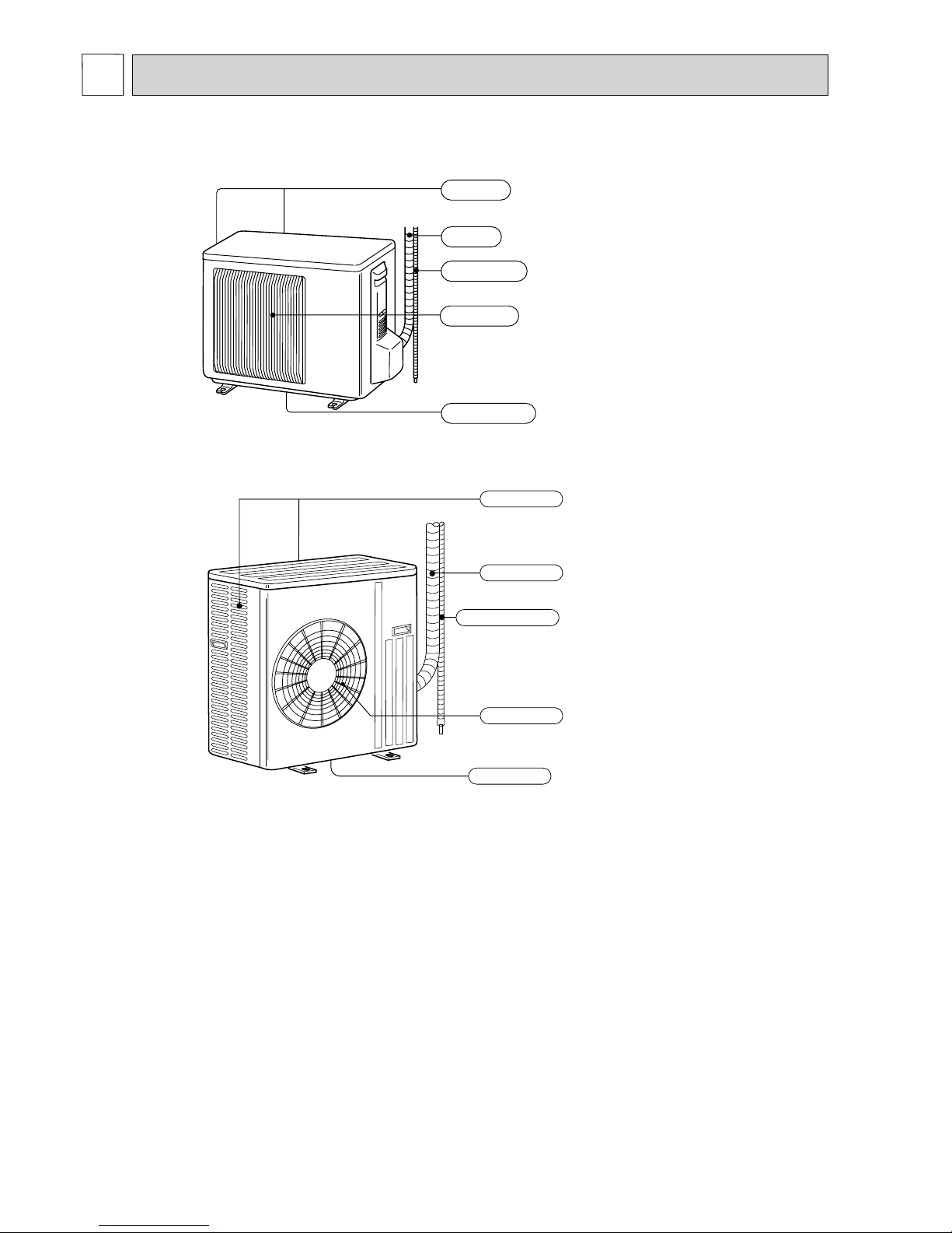
Air outlet
Drain outlet
Piping
Drain hose
Air inlet
(back and side)
Piping
Air outlet
Air inlet
(back and side)
Drain hose
Drain outlet
PART NAMES AND FUNCTIONS
2
MUZ-GE25VA MUZ-GE25VAD MUZ-GE33VA
MUZ-GE35VA MUZ-GE35VA2 MUZ-GE35VAD MUZ-GE42VA MUZ-GE42VAD
MUZ-GE50VA MUZ-GE50VA2 MUZ-GE50VAD
OBH532E
5
ACCESSORIES
Model
MUZ-GE25VA MUZ-GE25VAD
MUZ-GE33VA
MUZ-GE35VA MUZ-GE35VA2
MUZ-GE35VAD
MUZ-GE42VA MUZ-GE42VAD
MUZ-GE50VA
MUZ-GE50VA2
MUZ-GE50VAD
MUZ-GE60VA MUZ-GE60VAD
MUZ-GE71VA MUZ-GE71VAD
MUZ-GE80VA MUZ-GE80VA2
MUZ-GE80VAD
Drain socket 1 1 1
Drain cap - 2 -
Piping
Air outlet
Drain outlet
Air inlet
(back and side)
Drain hose
MUZ-GE60VA MUZ-GE60VAD MUZ-GE71VA MUZ-GE71VAD
MUZ-GE80VA MUZ-GE80VA2 MUZ-GE80VAD
OBH532E
6
Outdoor model MUZ-GE25VA-
A1
MUZ-GE25VA-
A2
MUZ-GE25VAD MUZ-GE33VA
Power supply
Single phase, 230 V, 50 Hz
Capacity
Rated frequency (Min.-Max.)
Cooling
kW
2.5 (1.1 - 3.5) 3.3(1.4 - 3.9)
Heating
3.2 (1.3 - 4.5) 3.2 (1.3 - 4.1) 3.2 (1.3 - 4.5) 4.0 (1.4 - 4.8)
Breaker Capacity
A10
Electrical data
Power input 1 (Total)
Cooling
W
560 910
Heating
730 1,030
Running current 1
(Total)
Cooling
A
2.9 4.3
Heating
3.8 4.8
Power factor 1 (Total)
Cooling
%
84 92
Heating
84 93
Starting current 1 (Total)
A 3.8 4.8
Coeffi cient of performance
(COP) 1 (Total)
Cooling
4.46 3.63
Heating
4.38 3.88
Compressor
Model
KNB073FFDHC KNB073FKVHC KNB092FFAHC
Output
W 550 650
Current 1
Cooling
A
2.44 3.70
Heating
3.30 4.30
Refrigeration oil
(Model)
L 0.32 (NEO22) 0.36 (NEO22) 0.32 (NEO22)
Fan motor
Model
RC0J50-DB
Current 1
Cooling
A
0.24 0.31
Heating
0.27
Dimensions W × H × D
mm 800 × 550 × 285
Weight
kg 30
Special remarks
Dehumidifi cation Cooling
L/h 0.2 0.6
Air fl ow 1
Cooling
High
m3/h
–
Med.
1,806 1,956
Low
1,170 1,806
Heating
High
2,106 2,130
Med.
1,806 1,956
Low
1,452 1,476
Sound level 1
Cooling
dB(A)
46 47
Heating
48
Fan speed
Cooling
High
rpm
–
Med.
740 800
Low
490 740
Heating
High
860 870
Med.
740 800
Low
600 610
Fan speed regulator
3
Refrigerant fi lling capacity
(R410A)
kg 0.80
NOTE: Test conditions are based on AS/NZS 3823.1.1.
Cooling: Indoor Dry-bulb temperature 27°C Wet-bulb temperature 19°C
Outdoor Dry-bulb temperature 35°C Wet-bulb temperature (24°C)
Heating: Indoor Dry-bulb temperature 20°C Wet-bulb temperature 15.5°C
Outdoor Dry-bulb temperature 7°C Wet-bulb temperature 6°C
Refrigerant piping length (one way): 5 m
1 Measured under rated operating frequency.
SPECIFICATION
3
OBH532E
7
Outdoor model
MUZ-GE35VA MUZ-GE35VA2-A1MUZ-GE35VA2-A2MUZ-GE35VAD MUZ-GE42VA MUZ-GE42VAD
Power supply
Single phase, 230 V, 50 Hz
Capacity
Rated frequency (Min.-Max.)
Cooling
kW
3.5 (1.4 - 3.9) 3.5 (1.1 - 4.0) 4.2(0.9-4.8)
Heating
4.0 (1.4 - 4.8) 4.0 (1.6 - 5.3) 5.4(1.4-6.0)
Breaker Capacity
A10
Electrical data
Power input 1 (Total)
Cooling
W
1,010 920 1,260
Heating
1,030 990 1,540
Running current 1
(Total)
Cooling
A
4.7 4.4 5.8
Heating
4.8 4.6 7.0
Power factor 1 (Total)
Cooling
%
93 91 94
Heating
93 94 96
Starting current 1 (Total)
A 4.8 4.6 7.0
Coeffi cient of performance
(COP) 1 (Total)
Cooling
3.47 3.80 3.33
Heating
3.88 4.04 3.51
Compressor
Model
KNB092FFAHC KNB092FNDHC SNB130FGBHT
Output
W 650 900
Current 1
Cooling
A
4.10 3.76 5.19
Heating
4.30 4.06 6.38
Refrigeration oil
(Model)
L 0.32 (NEO22) 0.45 (NEO22)
Fan motor
Model
RC0J50-DB RC0J50-EA
Current 1
Cooling
A
0.31 0.35 0.32
Heating
0.27 0.31
Dimensions W × H × D
mm 800 × 550 × 285
Weight
kg 30 33 36
Special remarks
Dehumidifi cation Cooling
L/h 0.8 0.9 1.4
Air fl ow 1
Cooling
High
m3/h
–
Med.
1,956 1,872
Low
1,806 1,776 1,086
Heating
High
2,130 2,016
Med.
1,956 1,776
Low
1,476 1,386
Sound level 1
Cooling
dB(A)
47 50
Heating
48 51
Fan speed
Cooling
High
rpm
–
Med.
800 810
Low
740 770 490
Heating
High
870
Med.
800 770
Low
610
Fan speed regulator
3
Refrigerant fi lling capacity
(R410A)
kg 0.80 1.15
NOTE: Test conditions are based on AS/NZS 3823.1.1.
Cooling: Indoor Dry-bulb temperature 27°C Wet-bulb temperature 19°C
Outdoor Dry-bulb temperature 35°C Wet-bulb temperature (24°C)
Heating: Indoor Dry-bulb temperature 20°C Wet-bulb temperature 15.5°C
Outdoor Dry-bulb temperature 7°C Wet-bulb temperature 6°C
Refrigerant piping length (one way): 5 m
1 Measured under rated operating frequency.
OBH532E
8
Outdoor model MUZ-GE50VA MUZ-GE50VA2 MUZ-GE50VAD
Power supply
Single phase, 230 V, 50 Hz
Capacity
Rated frequency (Min.-Max.)
Cooling
kW
5.0 (1.4 - 5.4) 4.8 (1.4 - 5.4)
Heating
5.8 (1.4 - 7.2)
Breaker Capacity
A16
Electrical data
Power input 1 (Total)
Cooling
W
1,640 1,480
Heating
1,650
Running current 1
(Total)
Cooling
A
7.4 6.8
Heating
7.4
Power factor 1 (Total)
Cooling
%
96 94
Heating
96
Starting current 1 (Total)
A 7.4
Coeffi cient of performance
(COP) 1 (Total)
Cooling
3.05 3.24
Heating
3.52
Compressor
Model
SNB130FGBHT
Output
W 900
Current 1
Cooling
A
6.69 6.09
Heating
6.72
Refrigeration oil
(Model)
L 0.45 (NEO22)
Fan motor
Model
RC0J60-AA
Current 1
Cooling
A
0.32
Heating
0.32
Dimensions W × H × D
mm 840 × 850 × 330
Weight
kg 54
Special remarks
Dehumidifi cation Cooling
L/h 1.8 1.6
Air fl ow 1
Cooling
High
m3/h
–
Med.
2,940
Low
1,740
Heating
High
–
Med.
2,940
Low
2,142
Sound level 1
Cooling
dB(A)
54
Heating
56
Fan speed
Cooling
High
rpm
–
Med.
780
Low
480
Heating
High
–
Med.
780
Low
580
Fan speed regulator
2
Refrigerant fi lling capacity
(R410A)
kg 1.55
NOTE: Test conditions are based on AS/NZS 3823.1.1.
Cooling: Indoor Dry-bulb temperature 27°C Wet-bulb temperature 19°C
Outdoor Dry-bulb temperature 35°C Wet-bulb temperature (24°C)
Heating: Indoor Dry-bulb temperature 20°C Wet-bulb temperature 15.5°C
Outdoor Dry-bulb temperature 7°C Wet-bulb temperature 6°C
Refrigerant piping length (one way): 5 m
1 Measured under rated operating frequency.
OBH532E
9
Outdoor model
MUZ-GE60VA
MUZ-GE60VAD
MUZ-GE71VA
MUZ-GE71VAD
MUZ-GE80VA MUZ-GE80VA2
MUZ-GE80VAD
Power supply
Single phase, 230 V, 50 Hz
Capacity
Rated frequency (Min.-Max.)
Cooling
kW
6.0 (1.5 - 7.5) 7.1 (2.4- 8.7)
8.0 (2.4 - 9.2)
7.8 (2.4 - 9.2)
Heating
6.8 (2.0 - 9.3) 8.1 (2.2 - 9.9) 9.0 (2.2 - 11.1)
Breaker Capacity
A20
Electrical data
Power input 1 (Total)
Cooling
W
1,760 2,130 2,560 2,460
Heating
1,770 2,110 2,540 2,550
Running current 1
(Total)
Cooling
A
7.8 9.4 11.3 10.8
Heating
7.8 9.5 11.2
Power factor 1 (Total)
Cooling
%
98 99 98 99
Heating
98 97 99
Starting current 1 (Total)
A 7.8 9.5 11.3 11.2
Coeffi cient of performance
(COP) 1 (Total)
Cooling
3.40 3.41 3.33 3.12 3.17
Heating
3.84 3.83 3.84 3.54 3.53
Compressor
Model
SNB130FGBMT SNB172FEKMT
Output
W 900 1,200
Current 1
Cooling
A
6.62 6.44 8.02 8.06 9.89 9.39 9.43
Heating
6.37 6.34 8.13 8.17 9.83 9.87
Refrigeration oil
(Model)
L 0.35 (FV50S) 0.4 (FV50S)
Fan motor
Model
RC0J60-BC
Current 1
Cooling
A
0.84 0.93 0.83 0.86
Heating
0.93 0.82
Dimensions W × H × D
mm 840 × 880 × 330
Weight
kg 50 53
Special remarks
Dehumidifi cation Cooling
L/h 1.9 2.2 2.9 2.7
Air fl ow 1
Cooling
High
m3/h
3,492 3,426
Med.
3,066 3,006
Low
1,692 1,512
Heating
High
2,952 2,892
Med.
2,952 2,892
Low
2,226 2,280
Sound level 1
Cooling
dB(A)
55
Heating
55
Fan speed
Cooling
High
rpm
950
Med.
840
Low
480 450
Heating
High
810
Med.
810
Low
620 650
Fan speed regulator
3
Refrigerant fi lling capacity
(R410A)
kg 1.55 1.90
NOTE: Test conditions are based on AS/NZS 3823.1.1.
Cooling: Indoor Dry-bulb temperature 27°C Wet-bulb temperature 19°C
Outdoor Dry-bulb temperature 35°C Wet-bulb temperature (24°C)
Heating: Indoor Dry-bulb temperature 20°C Wet-bulb temperature 15.5°C
Outdoor Dry-bulb temperature 7°C Wet-bulb temperature 6°C
Refrigerant piping length (one way): 5 m
1 Measured under rated operating frequency.
OBH532E
10
Specifi cations and rated conditions of main electric parts
Model
Item
MUZ-
GE25VA
MUZ-
GE25VAD
MUZ-
GE33VA
MUZ-
GE35VA
MUZ-
GE35VA2
MUZ-
GE35VAD
MUZ-
GE42VA
MUZ-
GE42VAD
MUZ-
GE50VA
MUZ-
GE50VA2
MUZ-
GE50VAD
Smoothing
capacitor
(C62, C63)
600 μF/620 μF 420 V —
(
C61
)
— 600 μF/620 μF 420 V
Diode module
(DB61) 15 A 600 V 25 A 600 V
(DB65) 25 A 600 V
Fuse
(F62) —
(F61) T20AL250V
(F701, F801, F901)
T3.15AL250V
(F601,F880, F901)
—
Intelligent
power module /
Power module
1.
(IC932) —
(IPM) 15 A 600 V 20 A 600 V
Expansion valve
coil
(LEV) 12 VDC
Reactor
(L61) 18 mH 23 mH
(L) —
Power factor
controller
(PFC) —
Current-limiting
PTC thermistor
(PTC64, PTC65) 33 Ω
Terminal block (TB1, TB2) 3 P
Relay
(X63) 3 A 250 V
(X64) 20 A 250 V
(X601) —
(X602) —
R.V.coil (21S4) 220 - 240 VAC
IGBT (TR821) 30 A 600 V
Specifi cations and rated conditions of main electric parts
Model
Item
MUZ-GE60VA
MUZ-GE60VAD
MUZ-GE71VA
MUZ-GE71VAD
MUZ-GE80VA MUZ-GE80VA2
MUZ-GE80VAD
Smoothing
capacitor
(C61, C62, C63)
—
(
CB1, CB2, CB3
)
560 μF 450 V
Diode module
(DB61) —
(DB65) —
Fuse
(F62)
T2.0AL250V
—
T2.0AL250V
—
T2.0AL250V
—
(F61) —
(F701, F801, F901)
—
(F601,F880, F901)
T3.15AL250V
Intelligent power
module
(IC932) 5A 600 V
(IPM) 20 A 600 V — 20 A 600 V — 20 A 600 V —
IGBT module (IC700) — 20 A 600 V — 20 A 600 V — 20 A 600 V
Expansion valve
coil
(LEV) 12 VDC
Reactor
(L61) —
(L) 340 μH
Power factor
controller
(PFC) 20 A 600 V — 20 A 600 V — 20 A 600 V —
(IC820) — 20 A 600 V — 20 A 600 V — 20 A 600 V
Current-limiting
PTC thermistor
(PTC64, PTC65) 33 Ω
Terminal block (TB1, TB2) 3 P
Relay
(X63) —
(X64) 20 A 250 V
(X601) 3 A 250V
(X602) 3 A 250V
R.V.coil (21S4) 220 - 240 VAC
IGBT (TR821) —
1.
Intelligent power module: MUZ-GE25VA -
A1
, MUZ-GE35/50VA
Power module: Other models
OBH532E
11
90
80
70
60
50
40
30
20
10
63 125 250 500 1000 2000 4000 8000
NC-60
NC-50
NC-40
NC-30
NC-20
NC-70
OCTAVE BAND SOUND PRESSURE LEVEL, 0 dB = 20μPa
BAND CENTER FREQUENCIES, Hz
COOLING
FUNCTION
SPL(dB(A)) LINE
HEATING
46
48
NC-10
NOISE CRITERIA CURVES
4
90
80
70
60
50
40
30
20
10
63 125 250 500 1000 2000 4000 8000
NC-60
NC-50
NC-40
NC-30
NC-20
NC-70
OCTAVE BAND SOUND PRESSURE LEVEL, 0dB = 20 μPa
BAND CENTER FREQUENCIES, Hz
COOLING
FUNCTION
SPL(dB(A)) LINE
HEATING
50
NC-10
51
90
80
70
60
50
40
30
20
10
63 125 250 500 1000 2000 4000 8000
NC-60
NC-50
NC-40
NC-30
NC-20
NC-70
OCTAVE BAND SOUND PRESSURE LEVEL, 0 dB = 20μPa
BAND CENTER FREQUENCIES, Hz
COOLING
FUNCTION
SPL(dB(A))
LINE
HEATING
47
48
NC-10
90
80
70
60
50
40
30
20
10
63 125 250 500 1000 2000 4000 8000
NC-60
NC-50
NC-40
NC-30
NC-20
NC-70
OCTAVE BAND SOUND PRESSURE LEVEL, 0 dB = 20μPa
BAND CENTER FREQUENCIES, Hz
COOLING
FUNCTION
SPL(dB(A))
LINE
HEATING
47
48
NC-10
MUZ-GE25VA
MUZ-GE25VAD
MUZ-GE42VA
MUZ-GE42VAD
MUZ-GE33VA
MUZ-GE35VA
MUZ-GE35VA2
MUZ-GE35VAD
OBH532E
12
90
80
70
60
50
40
30
20
10
63 125 250 500 1000 2000 4000 8000
NC-60
NC-50
NC-40
NC-30
NC-20
NC-70
BAND CENTER FREQUENCIES, Hz
COOLING
FUNCTION
SPL(dB(A)) LINE
HEATING
55
NC-10
55
OCTAVE BAND SOUND PRESSURE LEVEL, 0 dB = 20μPa
Test conditions
Cooling: Dry-bulb temperature 35°C Wet-bulb temperature (24°C)
Heating: Dry-bulb temperature 7°C Wet-bulb temperature 6°C
OUTDOOR UNIT
MICROPHONE
1 m
90
80
70
60
50
40
30
20
10
63 125 250 500 1000 2000 4000 8000
NC-60
NC-50
NC-40
NC-30
NC-20
NC-70
BAND CENTER FREQUENCIES, Hz
COOLING
FUNCTION
SPL(dB(A)) LINE
HEATING
55
NC-10
55
OCTAVE BAND SOUND PRESSURE LEVEL, 0 dB = 20μPa
90
80
70
60
50
40
30
20
10
63 125 250 500 1000 2000 4000 8000
NC-60
NC-50
NC-40
NC-30
NC-20
NC-70
OCTAVE BAND SOUND PRESSURE LEVEL, 0 dB = 20μPa
BAND CENTER FREQUENCIES, Hz
COOLING
FUNCTION
SPL(dB(A)) LINE
HEATING
54
NC-10
56
40
30
20
10
63 125 25
BAND
OCTAVE BAND SOUND
90
80
70
60
50
40
30
20
10
63 125 250 500 1000 2000 4000 8000
NC-60
NC-50
NC-40
NC-30
NC-20
NC-70
BAND CENTER FREQUENCIES, Hz
COOLING
FUNCTION
SPL(dB(A)) LINE
HEATING
55
NC-10
55
OCTAVE BAND SOUND PRESSURE LEVEL, 0 dB = 20μPa
MUZ-GE71VA
MUZ-GE71VAD
MUZ-GE60VA
MUZ-GE60VAD
MUZ-GE50VA
MUZ-GE50VA2
MUZ-GE50VAD
MUZ-GE80VA
MUZ-GE80VA2
MUZ-GE80VAD
OBH532E
13
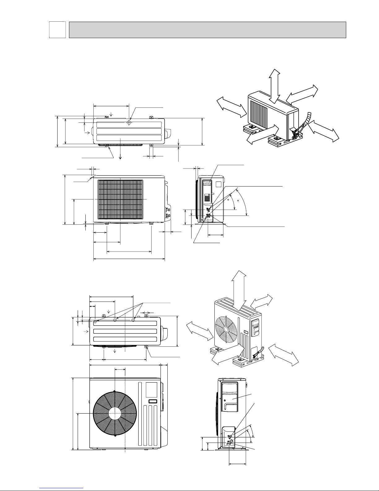
Unit: mm
10
69
800
302.5
500 Bolt pitch for installation
150
22.3
Handle
550
280
164.5
99.5
170.5
23
Service panel
Service port
285
344.5
44
400
Air in
Air out
Air in
17.5
Bolt pitch for
installation
304~325
40
Liquid refrigerant pipe joint
Refrigerant pipe (flared) ø6.35
Gas refrigerant pipe joint
Refrigerant pipe (flared) ø9.52
43
35
2 holes 10 X 21
REQUIRED SPACE
Basically open 100 mm or more
without any obstruction in front
and on both sides of the unit.
350 mm or more
200 mm or more
100 mm or more
100 mm or more
Open two sides of left,
right, or rear side.
Drain hole ø42
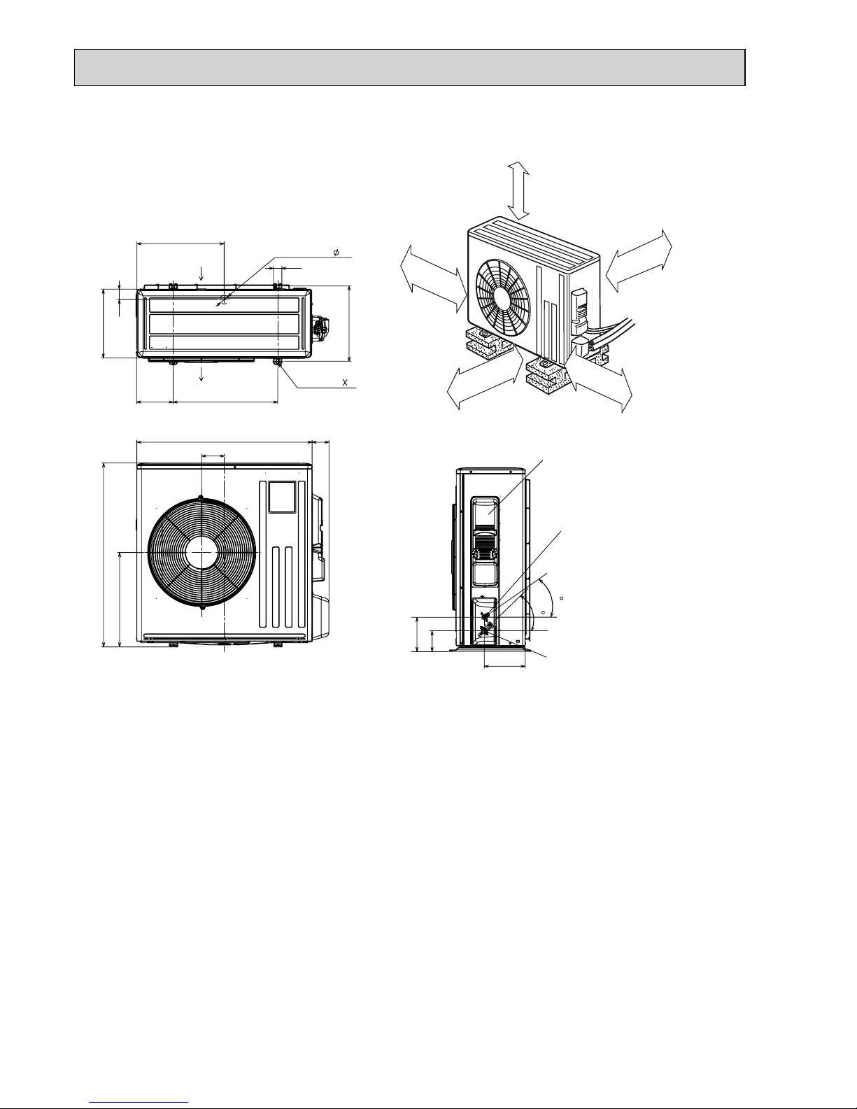
OUTLINES AND DIMENSIONS
5
30°
35°
155
90
198
40
515
299
66
34
51
330
360
850
430
500
80
121
840
Service panel
Gas refrigerant
pipe joint
Refrigerant pipe
(flared) ø12.7
Liquid refrigerant
pipe joint
Refrigerant pipe
(flared) ø6.35
170
Open as a rule
500 mm or more if
the front and both
sides are open
100 mm or more
200 mm or more if
there are obstacles
to both sides
Open as a rule
500 mm or more if the back,
both sides and top are open
350 mm or more
100 mm or more
REQUIRED SPACE
Air in
Air out
Air in
4 holes 10 × 21
Drain holes ø33
MUZ-GE50VA MUZ-GE50VA2 MUZ-GE50VAD
MUZ-GE25VA MUZ-GE25VAD MUZ-GE33VA
MUZ-GE35VA MUZ-GE35VA2 MUZ-GE35VAD MUZ-GE42VA MUZ-GE42VAD
OBH532E
14
417.5
40
42
Drain hole
175
500
330
50
Air in
Air out
2-holes 10 21
360
840
109
81
880
452
Service panel
99.5
164.5
195
35
44
Liquid refrigerant
pipe joint
Refrigerant pipe
(flared) Ø 6.35 (MUZ-GE60)
Ø 9.52 (MUZ-GE71/80)
Gas refrigerant
pipe joint
Refrigerant pipe
(flared)
Ø 15.88
350 mm or more
100 mm or more
REQUIRED SPACE
500 mm or more
100 mm or more
500 mm or more
MUZ-GE60VA MUZ-GE60VAD MUZ-GE71VA MUZ-GE71VAD
MUZ-GE80VA MUZ-GE80VA2 MUZ-GE80VAD
Unit: mm
OBH532E
15
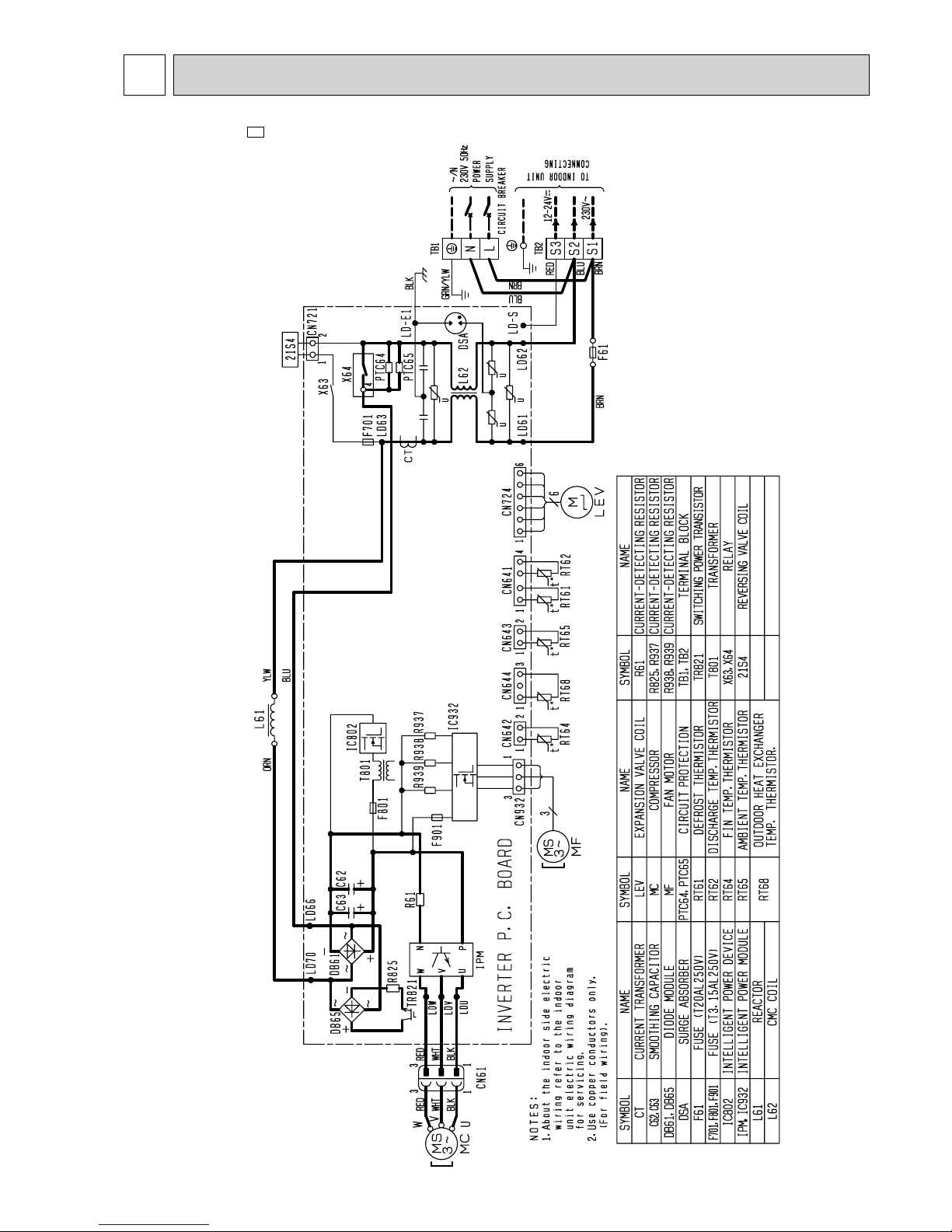
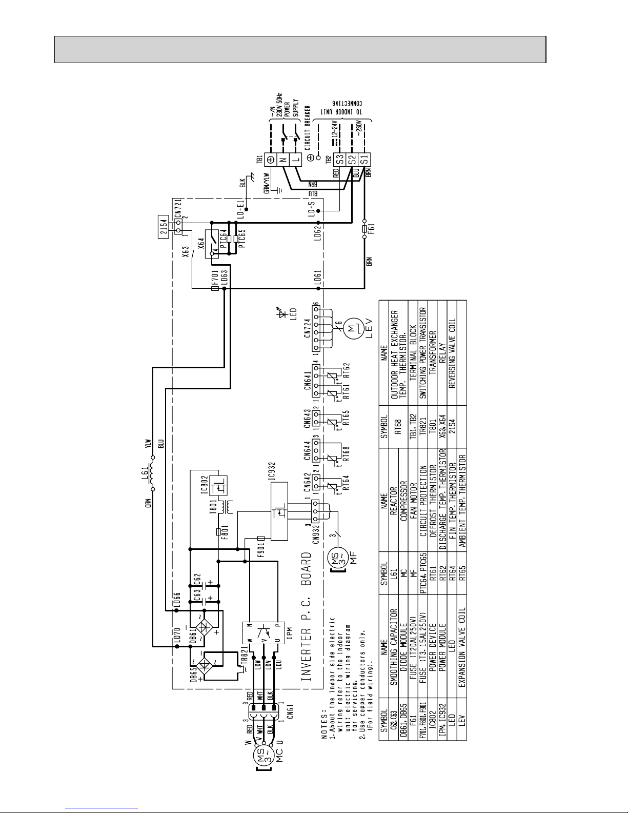
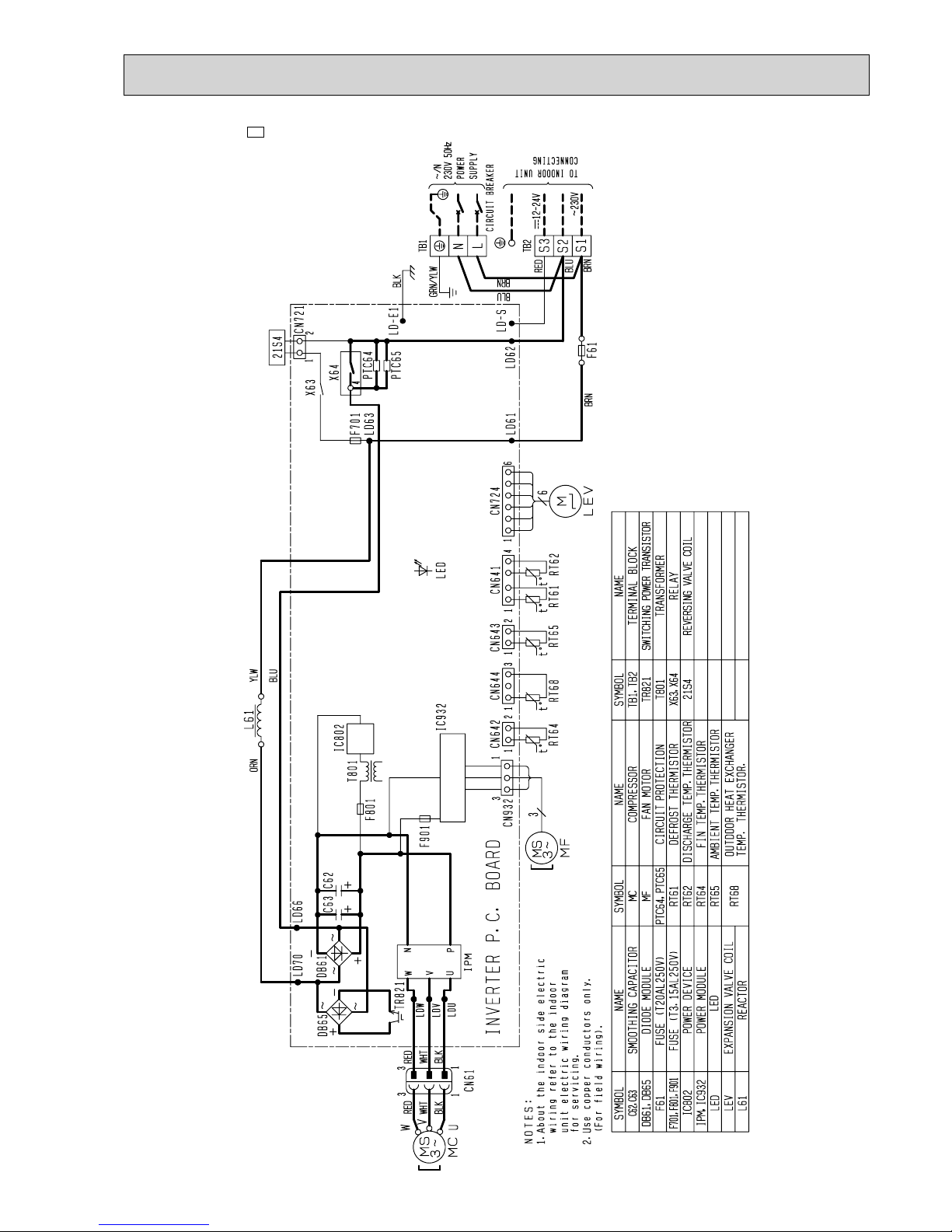
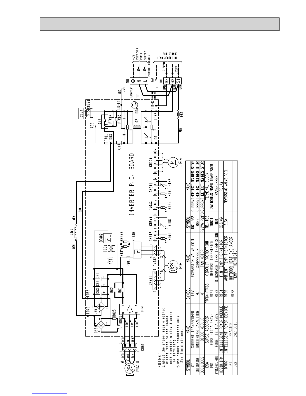
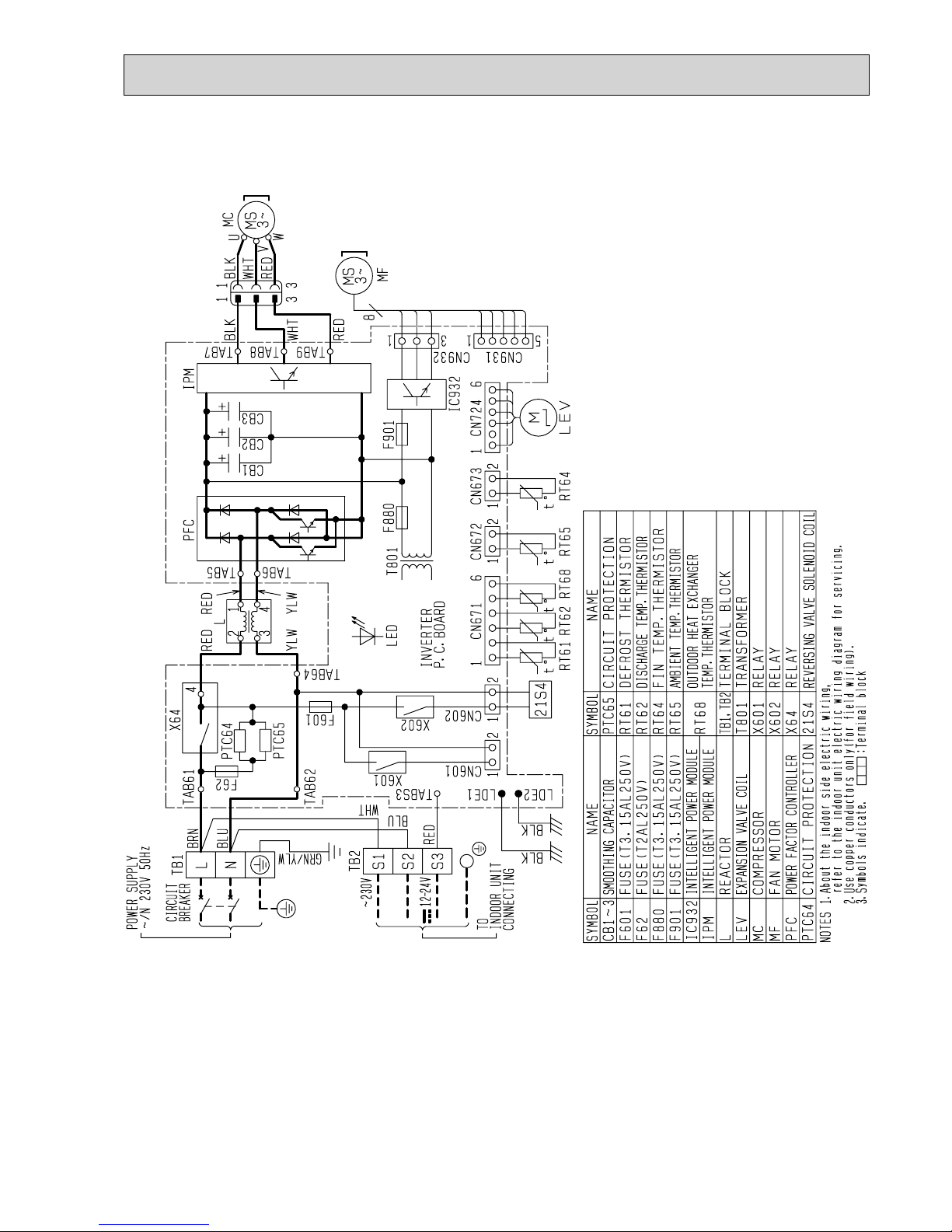
MUZ-GE25VA -A1 MUZ-GE35VA
WIRING DIAGRAM
6
OBH532E
16
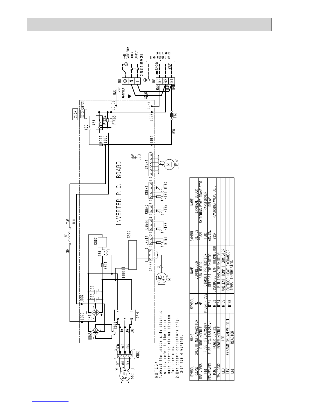
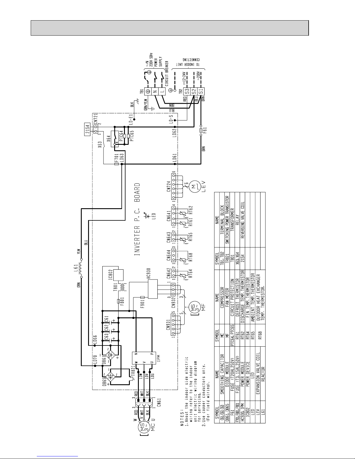
MUZ-GE33VA
OBH532E
17
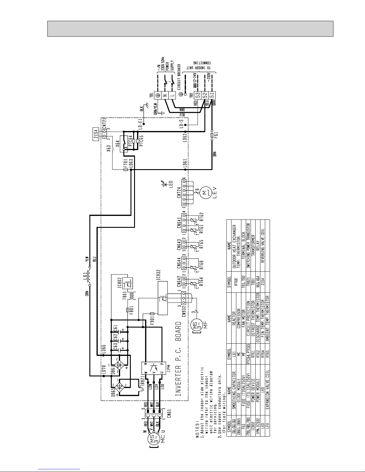
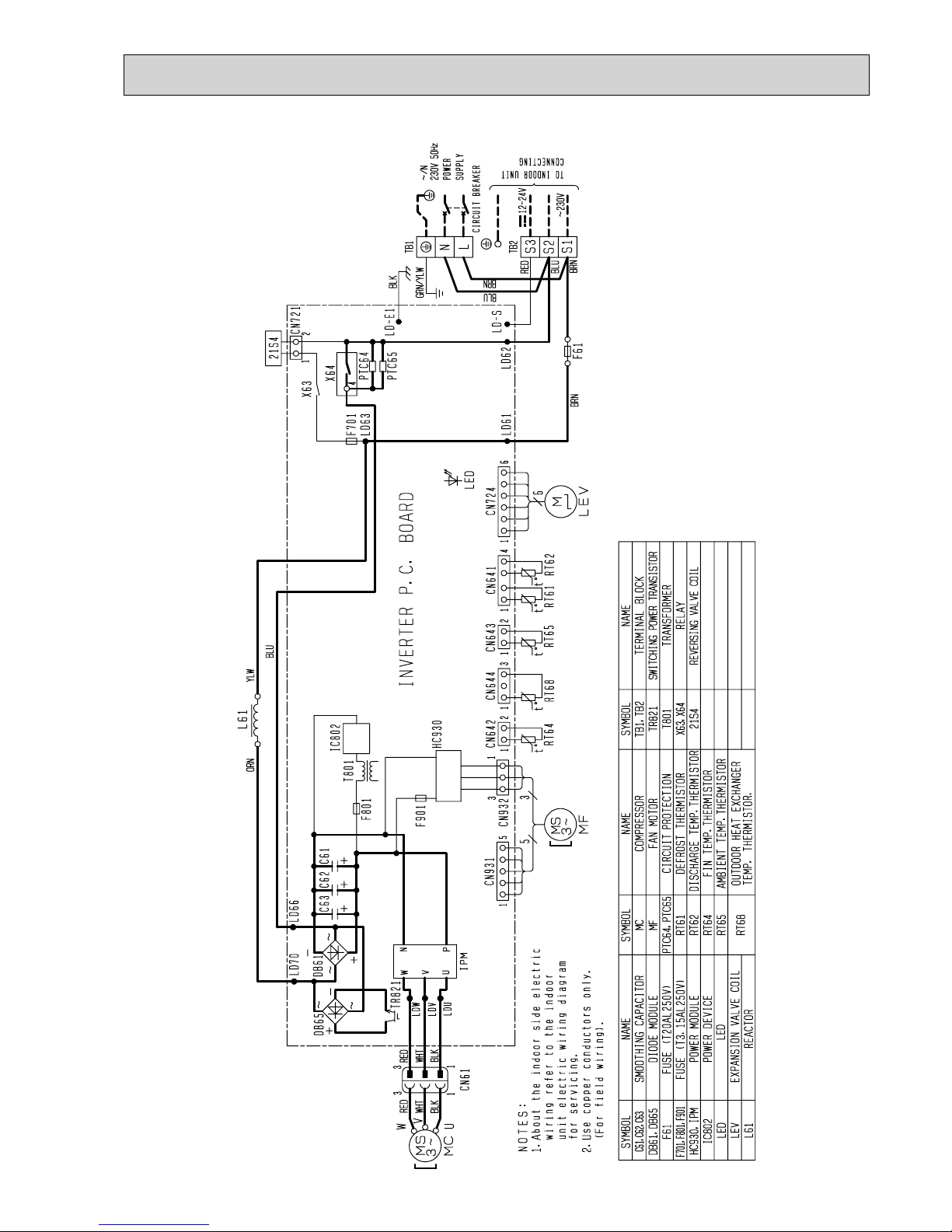
MUZ-GE25VA -A2 MUZ-GE35VA2
OBH532E
18
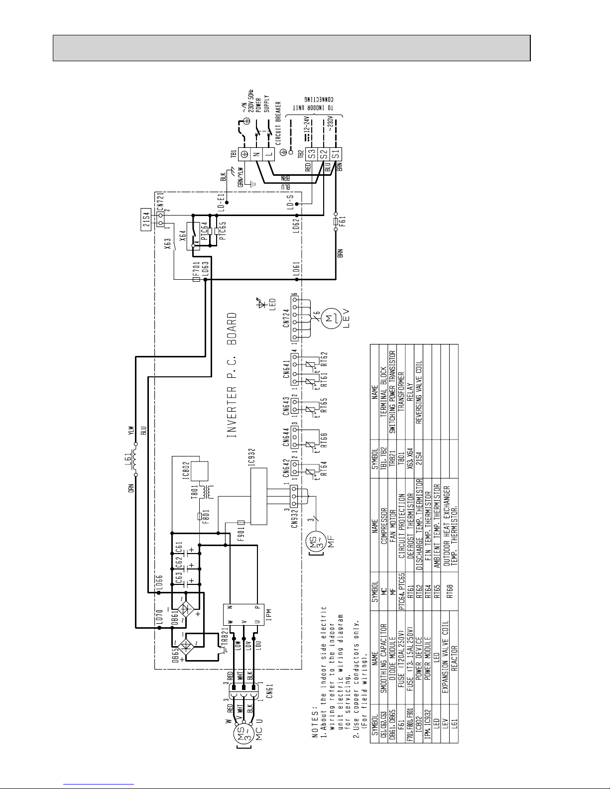
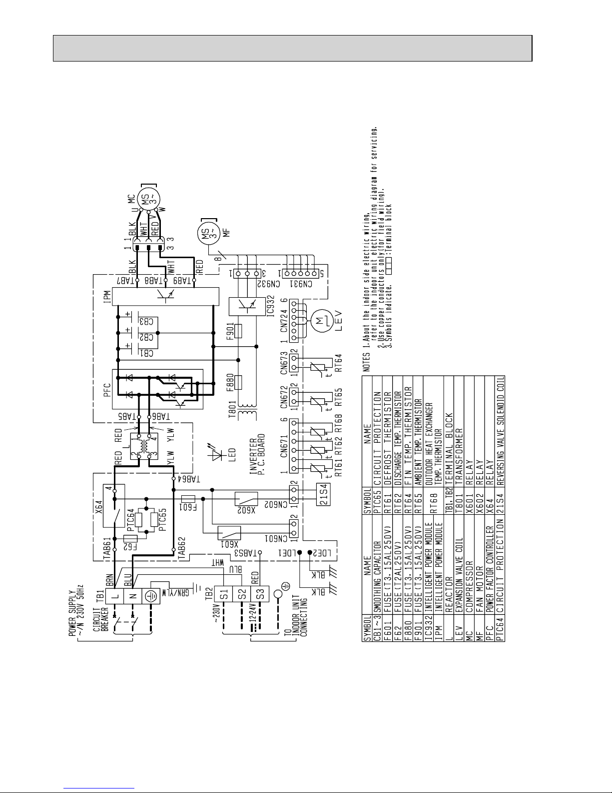
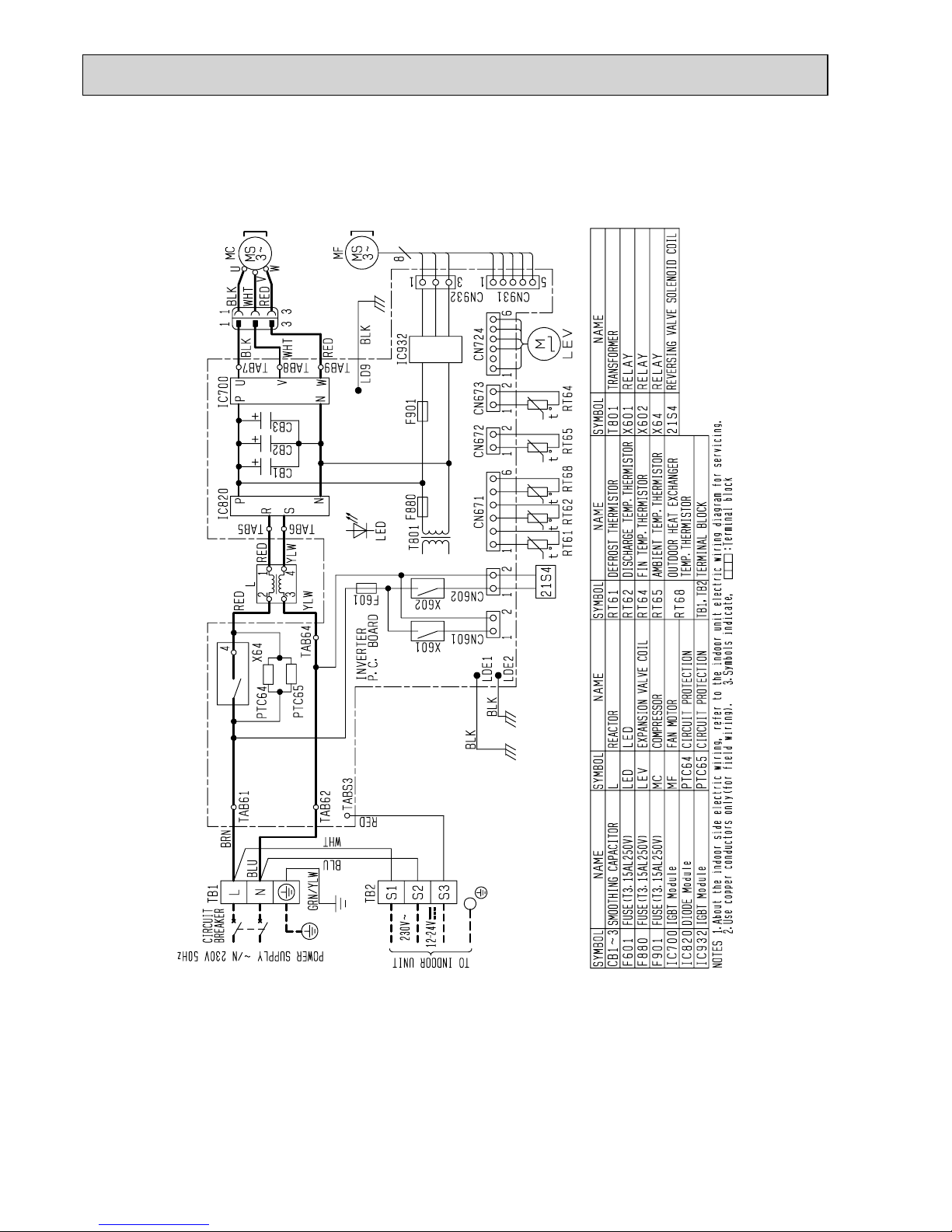
MUZ-GE25VAD MUZ-GE35VAD
OBH532E
19
MUZ-GE42VA
OBH532E
20
MUZ-GE42VAD
OBH532E
21
MUZ-GE50VA
OBH532E
22
MUZ-GE50VA2
OBH532E
23
MUZ-GE50VAD
OBH532E
24
MUZ-GE60VA MUZ-GE71VA MUZ-GE80VA
OBH532E
25
MUZ-GE80VA2
OBH532E
26
MUZ-GE60VAD MUZ-GE71VAD MUZ-GE80VAD
OBH532E
27
Unit: mm
Outdoor
heat
exchanger
Flared connection
Defrost
thermistor
RT61
Discharge
temperature
thermistor
RT62
Flared connection
Stop valve
(with strainar)
Stop valve
(with service port)
Refrigerant flow in cooling
Compressor
4-way valve
Refrigerant flow in heating
Refrigerant pipe ø9.52
(with heat insulator)
Refrigerant pipe ø6.35
(with heat insulator)
R.V. coil
heating ON
cooling OFF
Strainer
#100
LEV
Ambient
temperature
thermistor
RT65
Muffler
Capillary tube
ø3.0×ø2.0×240
Outdoor heat
exchanger
temperature
thermistor
RT68
Muffler
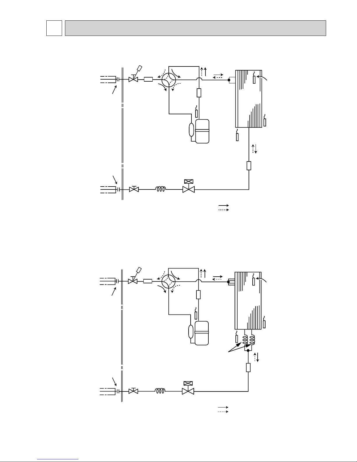
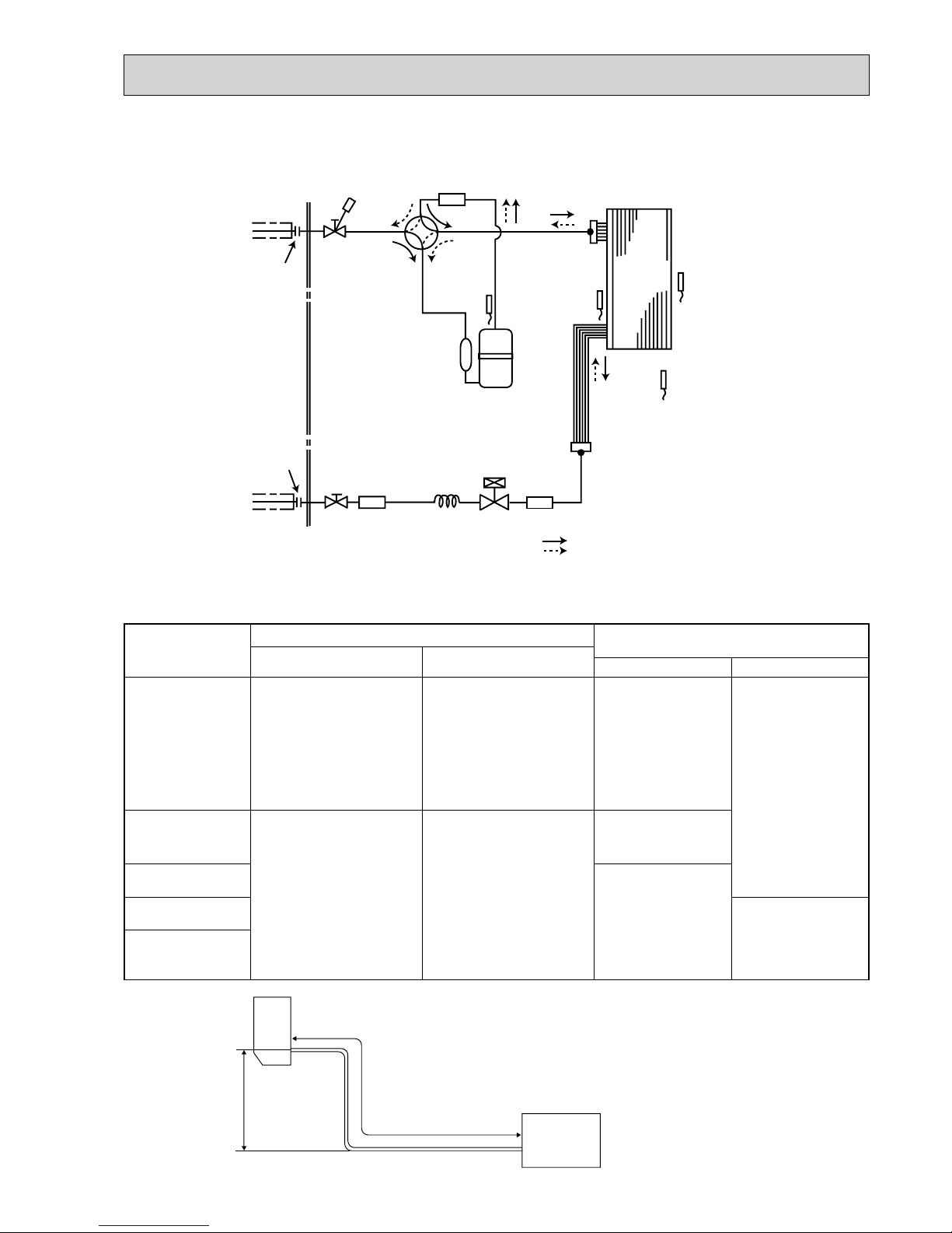
REFRIGERANT SYSTEM DIAGRAM
7
Outdoor
heat
exchanger
Flared connection
Defrost
thermistor
RT61
Discharge
temperature
thermistor
RT62
Flared connection
Stop valve
(with strainar)
Stop valve
(with service port)
Refrigerant flow in cooling
Compressor
4-way valve
Refrigerant flow in heating
Refrigerant pipe ø9.52
(with heat insulator)
Refrigerant pipe ø6.35
(with heat insulator)
R.V. coil
heating ON
cooling OFF
Strainer
#100
Capillary tube
ø3.0×ø1.8×600(×2)
LEV
Ambient
temperature
thermistor
RT65
Muffler
Capillary tube
ø3.0×ø2.0×240
Outdoor heat
exchanger
temperature
thermistor
RT68
Muffler
MUZ-GE25VA MUZ-GE25VAD MUZ-GE33VA MUZ-GE35VA
MUZ-GE35VA2 MUZ-GE35VAD MUZ-GE42VA MUZ-GE42VAD
OBH532E
28
Outdoor
heat
exchanger
Flared connection
Defrost
thermistor
RT61
Discharge
temperature
thermistor
RT62
Flared connection
Stop valve
Stop valve
(with service port)
Capillary tube
ø
4.0
×
ø
2.4×100
Refrigerant flow in cooling
Compressor
4-way valve
Refrigerant flow in heating
Refrigerant pipe
ø
15.88
(with heat insulator)
Refrigerant pipe ø6.35
(with heat insulator)
LEV
R.V. coil
heating ON
cooling OFF
Muffler
#100
Strainer
#100
Outdoor heat
exchanger
temperature
thermistor
RT68
Ambient
temperature
thermistor
RT65
Strainer
#100
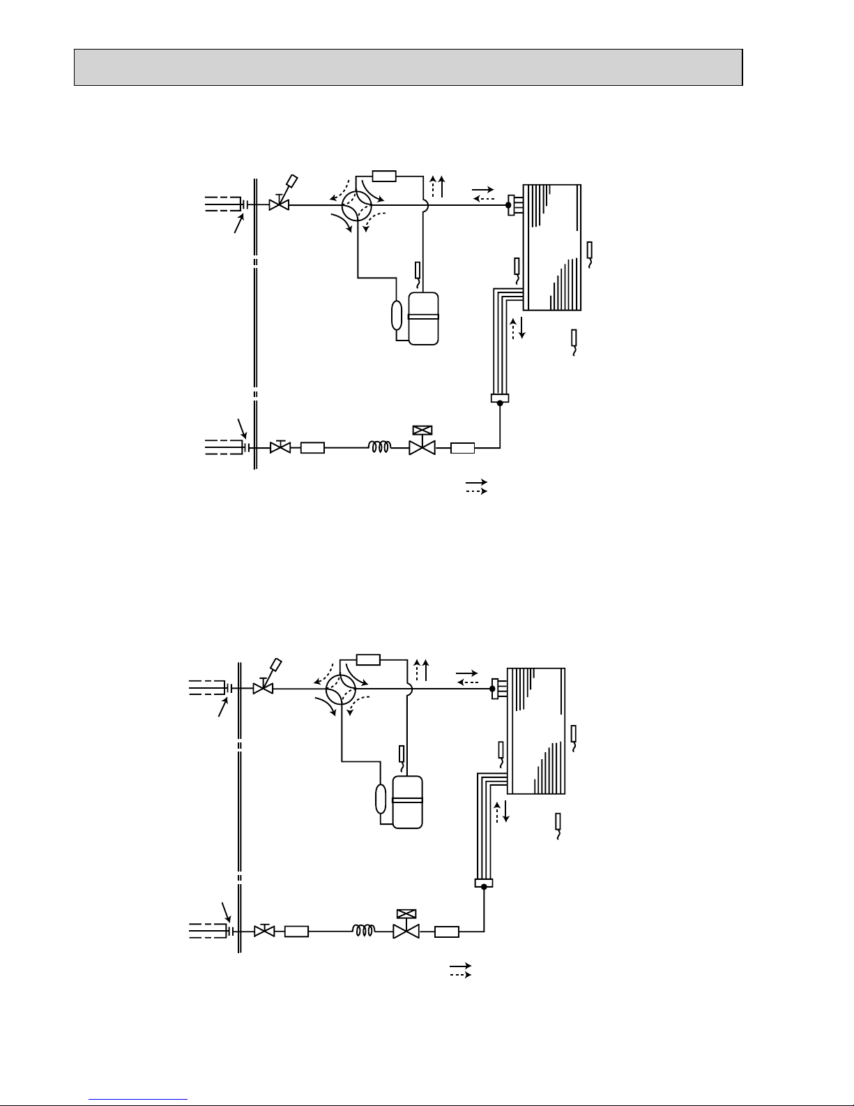
Unit: mm
Outdoor
heat
exchanger
Flared connection
Defrost
thermistor
RT61
Discharge
temperature
thermistor
RT62
Flared connection
Stop valve
(with strainar)
Stop valve
(with service port)
Capillary tube
ø
3.6
×
ø
2.4×50
Refrigerant flow in cooling
Compressor
4-way valve
Refrigerant flow in heating
Refrigerant pipe
ø
12.7
(with heat insulator)
Refrigerant pipe ø6.35
(with heat insulator)
LEV
R.V. coil
heating ON
cooling OFF
Muffler
#100
Receiver
Outdoor heat
exchanger
temperature
thermistor
RT68
Ambient
temperature
thermistor
RT65
Strainer
#100
MUZ-GE60VA MUZ-GE60VAD
MUZ-GE50VA MUZ-GE50VA2 MUZ-GE50VAD
OBH532E
29
Outdoor
heat
exchanger
Flared connection
Defrost
thermistor
RT61
Discharge
temperature
thermistor
RT62
Flared connection
Stop valve
Stop valve
(with service port)
Capillary tube
ø
4.0
×
ø
2.4×100
Refrigerant flow in cooling
Compressor
4-way valve
Refrigerant flow in heating
Refrigerant pipe
ø
15.88
(with heat insulator)
Refrigerant pipe ø9.52
(with heat insulator)
LEV
R.V. coil
heating ON
cooling OFF
Muffler
#100
Strainer
#100
Outdoor heat
exchanger
temperature
thermistor
RT68
Ambient
temperature
thermistor
RT65
Strainer
#100
Unit: mm
MUZ-GE71VA MUZ-GE71VAD
MUZ-GE80VA MUZ-GE80VA2 MUZ-GE80VAD
Max. Length
A
Max. Height
difference
B
Indoor
unit
Outdoor unit
MAX. REFRIGERANT PIPING LENGTH and MAX. HEIGHT DIFFERENCE
Refrigerant piping: m
Piping size O.D: mm
Max. Length
A
Max. Height difference
B
Gas Liquid
MUZ-GE25VA
MUZ-GE25VAD
MUZ-GE33VA
MUZ-GE35VA
MUZ-GE35VA2
MUZ-GE35VAD
MUZ-GE42VA
MUZ-GE42VAD
20 12 9.52
6.35
MUZ-GE50VA
MUZ-GE50VA2
MUZ-GE50VAD
30 15
12.7
MUZ-GE60VA
MUZ-GE60VAD
15.88
MUZ-GE71VA
MUZ-GE71VAD
9.52
MUZ-GE80VA
MUZ-GE80VA2
MUZ-GE80VAD
OBH532E
 Loading...