

Mitsubishi MSZ-GE06NA, MSY-GE09NA, MSY-GE12NA, MSY-GE15NA, MSY-GE18NA Service Manual
...
SPLIT-TYPE AIR CONDITIONERS
INDOOR UNIT
SERVICE MANUAL
Models
MSZ-GE06NA
MSZ-GE09NA
MSZ-GE12NA
MSZ-GE15NA
MSZ-GE18NA
MSZ-GE06NAMSZ-GE09NAMSZ-GE12NAMSZ-GE15NAMSZ-GE18NA-
8,9
8,9
8,9
8,9
8,9
Revision D:
• MSZ-GE06/09/12/15/18NA-9 and MSYGE09/12/15/18NA-
Please void OBH548 REVISED EDITION-C
9
have been added.
No. OBH548
REVISED EDITION-D
MSZ-GE24NA
MSY-GE09NA
MSY-GE12NA
MSY-GE15NA
MSY-GE18NA
MSY-GE24NA
MSZ-GE06/09/12/15/18NA
MSY-GE09/12/15/18NA
MSY-GE09NAMSY-GE12NAMSY-GE15NAMSY-GE18NA-
CONTENTS
1. TECHNICAL CHANGES
2. PART NAMES AND FUNCTIONS ·····················3
3. SPECIFICATION ················································ 5
4. OUTLINES AND DIMENSIONS ························7
5. WIRING DIAGRAM ············································9
6. REFRIGERANT SYSTEM DIAGRAM ············· 11
7. SERVICE FUNCTIONS ···································12
8. MICROPROCESSOR CONTROL ···················14
9. TROUBLESHOOTING ·····································21
10. DISASSEMBLY INSTRUCTIONS ···················· 40
8,9
8,9
8,9
8,9
Outdoor unit service manual
MUZ-GE•NA MUY-GE•NA
Series (OBH549)
MXZ-B·NA Series (OB444)
·······································
2
NOTE:
RoHS compliant products have <G> mark on the spec name plate.
PARTS CATALOG (OBB548)
Use the specifi ed refrigerant only
OBH548D
Never use any refrigerant other than that specified.
Doing so may cause a burst, an explosion, or fire when the unit is being used, serviced, or disposed of.
Correct refrigerant is specified in the manuals and on the spec labels provided with our products.
We will not be held responsible for mechanical failure, system malfunction, unit breakdown or accidents caused by
failure to follow the instructions.
Revision A:
• MSZ-GE24NA and MSY-GE24NA have been added.
Revision B:
• MSZ-GE06/09/12/15/18NA-8 and MSY-GE09/12/15/18NA-8 have been added.
Revision C:
• Specification has been corrected.
2.7
pt./h
5.1
The value of "Moisture removal" for MSZ-GE24NA and MSY-GE24NA has been corrected. [
Revision D:
• MSZ-GE06/09/12/15/18NA-9 and MSY-GE09/12/15/18NA-9 have been added.
pt./h]
1
TECHNICAL CHANGES
MSZ-GE06NA MSZ-GE09NA MSZ-GE12NA MSZ-GE15NA MSZ-GE18NA MSZ-GE24NA
MSY-GE09NA MSY-GE12NA MSY-GE15NA MSY-GE18NA MSY-GE24NA
1. New model
MSZ-GE06NA
MSZ-GE09NA
MSZ-GE12NA
MSZ-GE15NA
MSZ-GE18NA
MSY-GE09NA
MSY-GE12NA
MSY-GE15NA
MSY-GE18NA
1. These models have been modified to be compatible with Honeywell remote controller.
2. Indoor electronic control P.C. board has been changed.
MSZ-GE06NA MSZ-GE09NA MSZ-GE12NA MSZ-GE15NA MSZ-GE18NA MSY-GE09NA MSY-GE12NA MSY-GE15NA MSY-GE18NA -
MSZ-GE06NA MSZ-GE09NA MSZ-GE12NA MSZ-GE15NA MSZ-GE18NA MSY-GE09NA MSY-GE12NA MSY-GE15NA MSY-GE18NA -
8
8
8
8
8
8
8
8
8
MSZ-GE06NA MSZ-GE09NA MSZ-GE12NA MSZ-GE15NA MSZ-GE18NA MSY-GE09NA MSY-GE12NA MSY-GE15NA MSY-GE18NA -
8
8
8
8
8
8
8
8
8
9
9
9
9
9
9
9
9
9
1. Model name has been changed.
2. New service parts numbers (Refer to OBB548 1-9 to 1-12.)
2
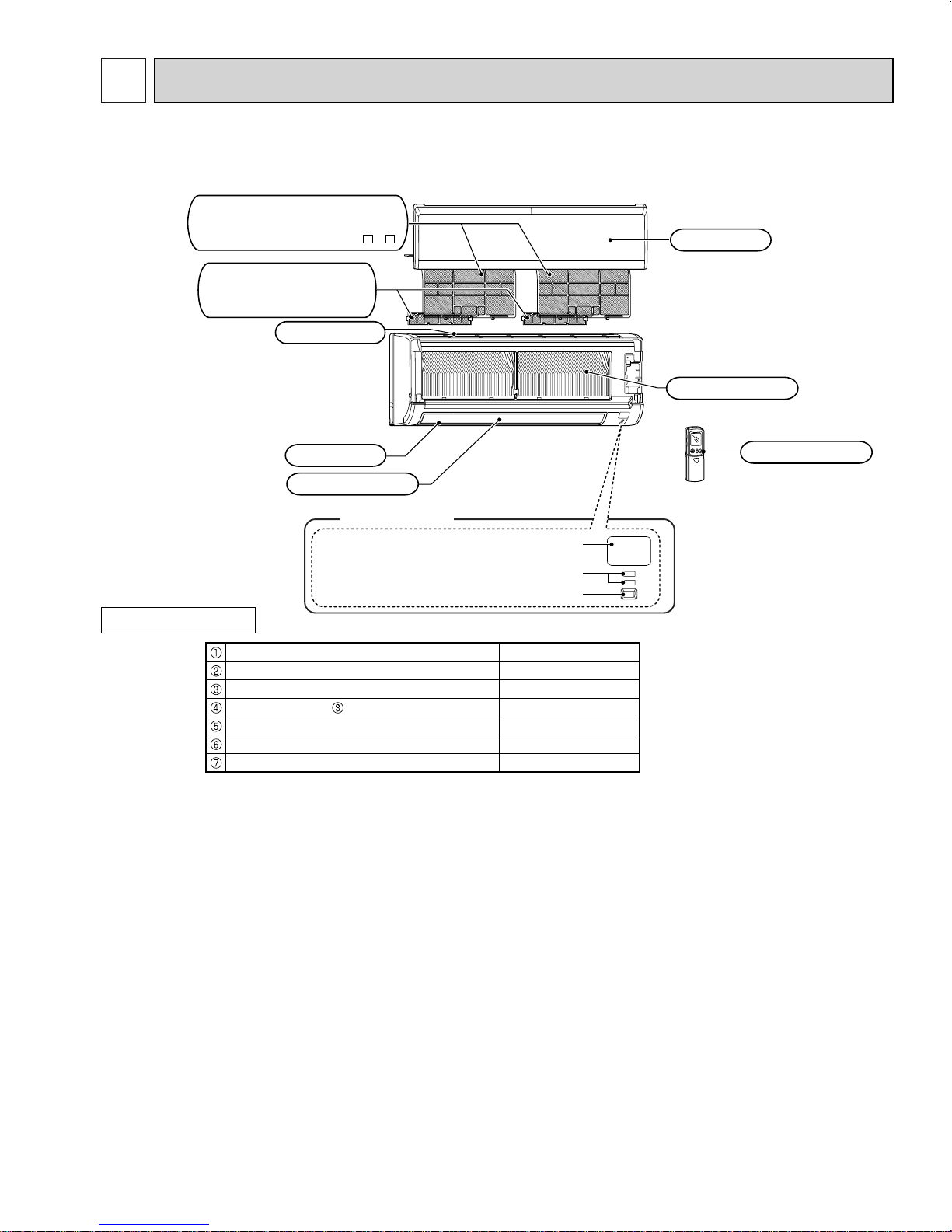
Remote controller
Operation indicator lamp
Remote control receiving section
Emergency operation switch (E.O. SW)
Horizontal vane
Air outlet
Air ¿ lter
[Catechin air ¿ lter
(GENA)
]
Air inlet
Heat exchanger
Front panel
Air cleaning ¿ lter
(Anti-Allergy Enzyme
Filter)
[Nano platinum ¿ lter
(GENA-
8 ,
- 9 )
]
Display section
2
OBH548D
PART NAMES AND FUNCTIONS
MSZ-GE06NA MSZ-GE09NA MSZ-GE12NA MSZ-GE15NA MSZ-GE18NA
MSY-GE09NA MSY-GE12NA MSY-GE15NA MSY-GE18NA
ACCESSORIES
Installation plate 1
Installation plate fi xing screw 4 × 25 mm 5
Remote controller holder 1
Fixing screw for 3.5 × 16 mm (Black) 2
Battery (AAA) for remote controller 2
Wireless remote controller 1
Felt tape (Used for left or left-rear piping) 1
3
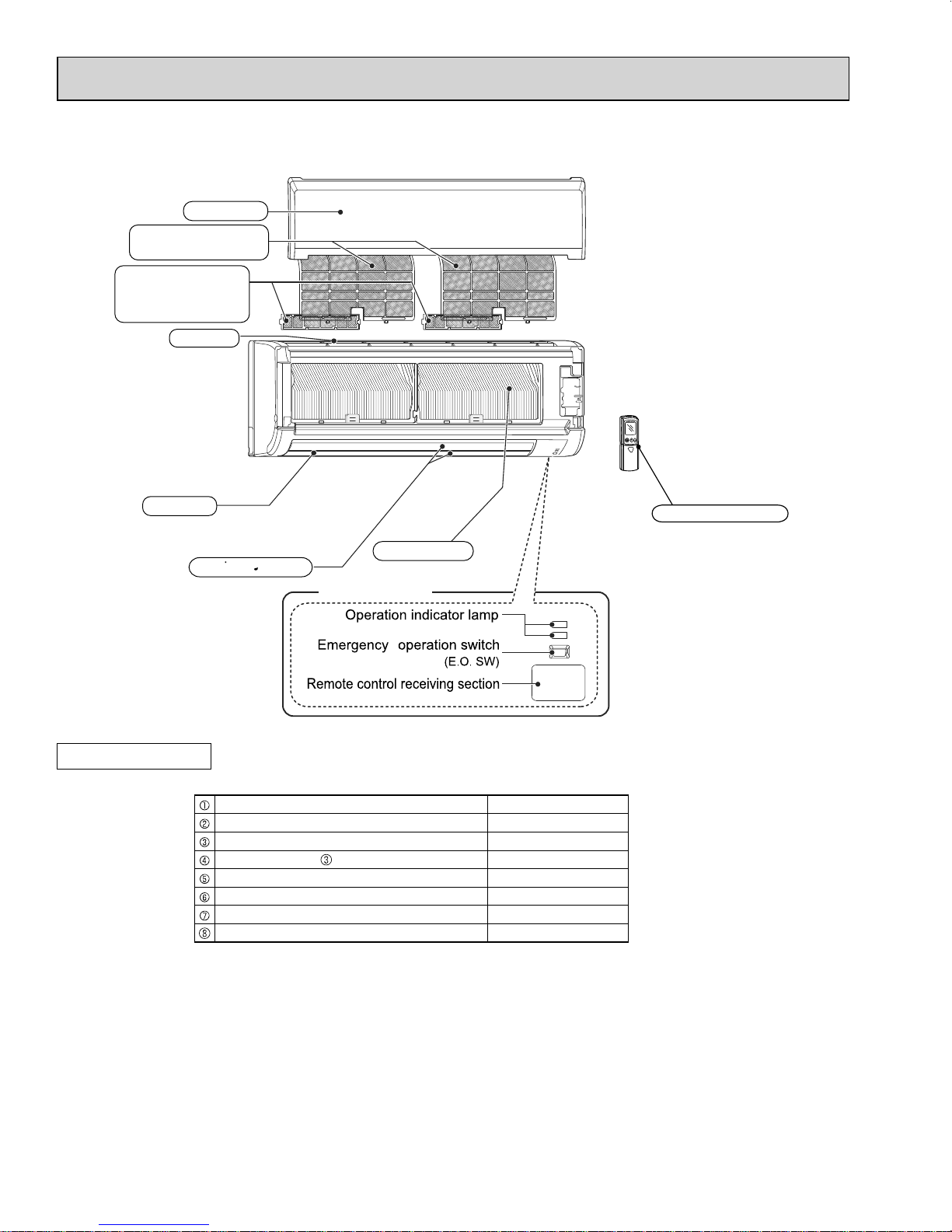
MSZ-GE24NA
OBH548D
MSY-GE24NA
Air fi lter
(Nano platinum filter)
Air cleaning filter
(Electrostatic anti-allergy
enzyme filter)
Front panel
Air inlet
Air outlet
ACCESSORIES
Remote controller
Heat exchanger
Horizontal vane
Display section
Installation plate 1
Installation plate fi xing screw 4 × 25 mm 7
Remote controller holder 1
Fixing screw for 3.5 × 16 mm (Black) 2
Battery (AAA) for remote controller 2
Wireless remote controller 1
Felt tape (Used for left or left-rear piping) 1
Air cleaning fi lter 2
4
3
OBH548D
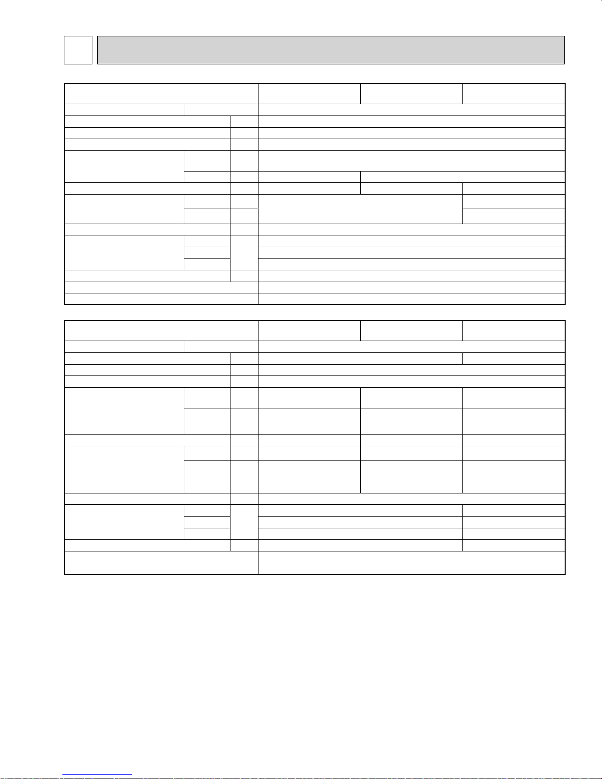
SPECIFICATION
Indoor model MSZ-GE06NA
Power supply V, phase, Hz 208/230, 1, 60
Max. fuse size (time delay)/ Disconnect switch
Min. circuit ampacity A 1.0
Fan motor F.L.A 0.76
Airfl ow
Super High - High - Med. Low - Quiet
Moisture removal pt./h – 1.5 2.5
Sound level
Super High - High - Med. Low - Quiet
Cond. drain connection O.D. in. 5/8
Dimensions
Weight Ib. 22
External fi nish Munsell 1.0Y 9.2/0.2
Control voltage (by built-in transformer) 12 - 24 VDC
Indoor model
Power supply V, phase, Hz 208/230, 1, 60
Max. fuse size (time delay)/ Disconnect switch
Min. circuit ampacity A 1.0
Fan motor F.L.A 0.76
Airfl ow
Super High - High - Med. Low - Quiet (GE15/18)
Powerful - High - Med - Low
(GE24)
Moisture removal pt./h 2.7 4.6 5.1
Sound level
Super High - High - Med. Low - Quiet (GE15/18)
Powerful - High - Med - Low
(GE24)
Cond. drain connection O.D. in. 5/8
Dimensions
Weight Ib. 22 37
External fi nish Munsell 1.0Y 9.2/0.2
Control voltage (by built-in transformer) 12 - 24 VDC
NOTE: Test conditions are based on AHRI 210/240.
COOL Dry
HEAT Dry CFM 406-321-233-170-145 406-321-237-170-145
Cooling dB(A)
Heating dB(A) 43-37-30-22-19
W
D 9-1/8
H 11-5/8
COOL Dry
HEAT Dry CFM 463-367-304-247-205 512-431-339-275-230 738-628-469-388
Cooling dB(A) 49-44-38-32-26 49-44-38-33-28
Heating dB(A) 46-40-35-30-26 49-43-38-33-28
W
D 9-1/8 9-3/8
H 11-5/8 12-13/16
A15
CFM
(Wet)
43-37-30-22-19
in.
MSZ-GE15NA
MSY-GE15NA
A15 20
(Wet)
CFM
in.
533-420-335-272-205
(498-385-300-237-170)
31-7/16 43-5/16
MSZ-GE09NA
MSY-GE09NA
399-321-237-170-145
(364-286-201-134-109)
31-7/16
MSZ-GE18NA
MSY-GE18NA
533-420-339-275-230
( 498-385-304-240-194)
MSZ-GE12NA
MSY-GE12NA
45-37-30-22-19
MSZ-GE24NA
MSY-GE24NA
738-628-469-388
(661-562-420-347)
53-49-41-34
52-49-41-32
5
3-1. OPERATING RANGE
OBH548D
(1) POWER SUPPLY
Rated voltage Guaranteed voltage (V)
Min. 187
Indoor unit
208/230 V
1 phase
60 Hz
(2) OPERATION
Mode Condition
Standard temperature 80 67 95 —
Cooling
Heating
Maximum temperature 90 73 115 —
Minimum temperature 67 57 14 —
Maximum humidity 78% —
Standard temperature 70 60 47 43
Maximum temperature 80 67 75 65
Minimum temperature 70 60 -4 -5
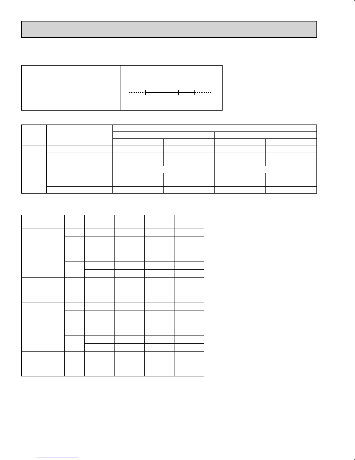
3-2. OUTLET AIR SPEED AND COVERAGE
Model Mode Function
HEAT Dry 406 20.6 29.5
MSZ-GE06NA
MSZ-GE09NA
MSY-GE09NA
MSZ-GE12NA
MSY-GE12NA
MSZ-GE15NA
MSY-GE15NA
MSZ-GE18NA
MSY-GE18NA
MSZ-GE24NA
MSY-GE24NA
COOL
HEAT Dry 406 20.6 29.5
COOL
HEAT Dry 406 20.6 29.5
COOL
HEAT Dry 463 23.4 33.5
COOL
HEAT Dry 512 25.9 36.9
COOL
HEAT Dry 738 18.0 36.9
COOL
Dry 321 16.3 23.5
Wet 286 14.5 21.0
Dry 321 16.3 23.5
Wet 286 14.5 21.0
Dry 321 16.3 23.5
Wet 286 14.5 21.0
Dry 420 21.3 30.5
Wet 385 19.5 28.0
Dry 420 21.3 30.5
Wet 385 19.5 28.0
Dry 738 18.0 36.9
Wet 661 16.1 33.2
Airfl ow
(CFM)
208 230 Max. 253
Intake air temperature (°F)
Indoor Outdoor
DB WB DB WB
Air speed
(ft./s.)
Coverage
● The air coverage is the figure up to the
(ft.)
position where the air speed is 1 ft./s.,
when air is blown out horizontally from
the unit properly at the High speed position.
The coverage should be used only as a
general guideline since it varies according to the size of the room and furniture
arranged inside the room.
6
4
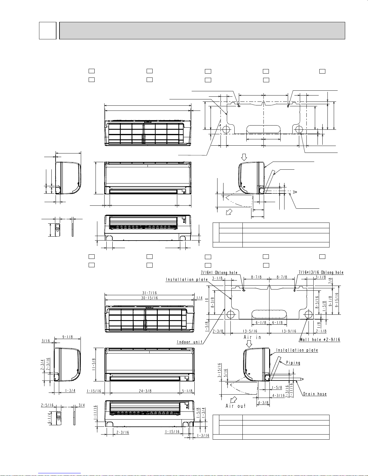
OBH548D
OUTLINES AND DIMENSIONS
MSZ-GE06NA MSZ-GE09NA MSZ-GE12NA MSZ-GE15NA MSZ-GE18NA
MSY-GE09NA MSY-GE12NA MSY-GE15NA MSY-GE18NA
MSZ-GE06NA- 8 MSZ-GE09NA- 8 MSZ-GE12NA- 8 MSZ-GE15NAMSY-GE09NA-
3/16
2-3/4
1-3/4
2- 5/16
9-1/8
2-3/16
6 - 1/4
8
MSY-GE12NA- 8 MSY-GE15NA- 8 MSY-GE18NA-
3/4
11-5/8
1-11/16
2-3/16
7/16×1 Oblong hole
Installation plate
31-7/16
30-15/16 1/4
Indoor unit
5-1/824-3/81-15/16
1-15/16
3-1/8
10
8-3/8
1-5/8
5/16
3-15/16
Air out
Insulation ø1 - 3/8 O.D
1-5/8
Liquid line ø1/4 19 - 11/16 (Flared connection ø1/4)
Gas line ø3/8 16 - 15/16
Piping
Drain hose Insulation ø1-1/8 O.D Connected part ø5/8 O.D
13-5/162-3/8
Air in
(Flared connection: ø3/8 (GE06/09/12NA), ø1/2 (GE15/18NA))
8
MSZ-GE18NA- 8
8
8-7/8 8-7/8
6-1/8 6-1/8
Installation plate
1-5/8
4/3/16
4-3/8
13-9/16 2-1/8
Piping
2-3/16
7/16×13/16 Oblong hole
3-1/8
Wall hole ø2-9/16
Drain hose
2-11/16
Unit: inch
7/8
9-15/16
9-1/8
8-5/16
1/8
1-5/8
MSZ-GE06NA- 9 MSZ-GE09NA- 9 MSZ-GE12NA- 9 MSZ-GE15NAMSY-GE09NA- 9 MSY-GE12NA- 9 MSY-GE15NA- 9 MSY-GE18NA-
Insulation ø1 - 3/8 O.D
Liquid line ø1/4 19 - 11/16 (Flared connection ø1/4)
Gas line ø3/8 16 - 15/16
Piping
Drain hose Insulation ø1-1/8 O.D Connected part ø5/8 O.D
(Flared connection: ø3/8 (GE06/09/12NA), ø1/2 (GE15/18NA))
9
MSZ-GE18NA- 9
9
7
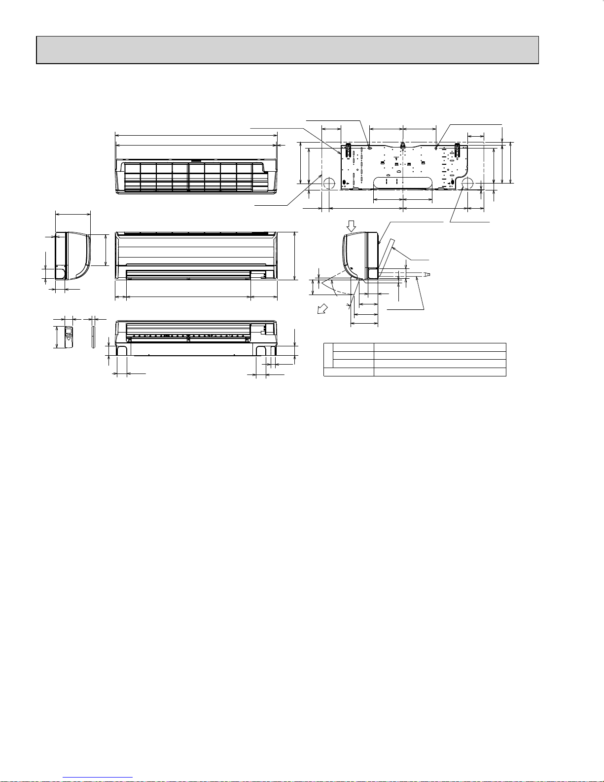
MSZ-GE24NA
OBH548D
MSY-GE24NA
43-5/16
42-7/8 3/16
Installation plate
7/16×1 Oblong hole
5-1/16
8-7/8 8-7/8
7/16×3/4 Oblong hole
4-5/16
27/32
3/16
2-9/16
2-5/16
6-1/4
9-3/8
2-1/2
8-1/4
3 33-1/8 7-1/8
3/4
2-1/2
2-9/16
Indoor unit
1-3/16
2-9/16
9-7/16
11-1/16
1-3/4
1-15/16 19-3/4 17-5/16
Air in
12-13/16
1/2
3-15/16
(
70°
)
4-7/8
Air out
2-1/2
6-5/16
7-1/4
Insulation Ø2 O.D
Liquid line Ø3/8 19-11/16 (Flared connection Ø3/8)
Piping
Gas line Ø1/2 16-15/16 (Flared connection Ø5/8)
Drain hose
Insulation Ø1-1/8 Connected part Ø5/8 O.D
7-27/327-27/32
Installation plate
Piping
2-5/8
2-9/16
1/8
Drain hose
4-3/8
Wall hole Ø3
1/8
11
10-3/16
1-3/4 9-3/8
8
5
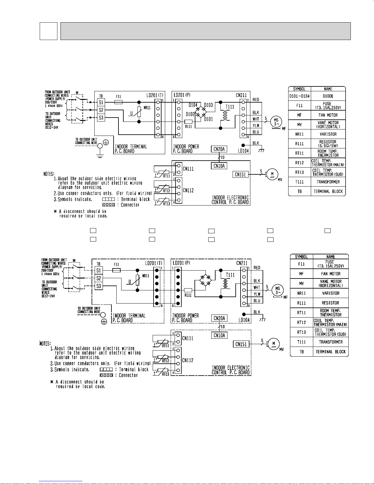
OBH548D
WIRING DIAGRAM
MSZ-GE06NA MSZ-GE09NA MSZ-GE12NA MSZ-GE15NA MSZ-GE18NA
MSY-GE09NA MSY-GE12NA MSY-GE15NA MSY-GE18NA
MSZ-GE06NA- 8 MSZ-GE09NA- 8 MSZ-GE12NA- 8 MSZ-GE15NAMSY-GE09NA- 8 MSY-GE12NA- 8 MSY-GE15NA- 8 MSY-GE18NA-
8
MSZ-GE18NA- 8
8
9
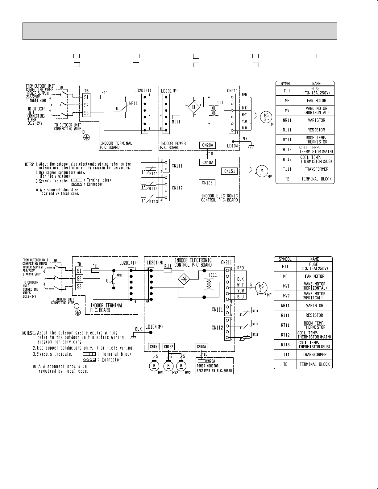
MSZ-GE06NA- 9 MSZ-GE09NA- 9 MSZ-GE12NA- 9 MSZ-GE15NA-
OBH548D
9
MSY-GE09NA-
MSY-GE12NA- 9 MSY-GE15NA- 9 MSY-GE18NA-
MSZ-GE24NA
MSY-GE24NA
9
MSZ-GE18NA- 9
9
10
6
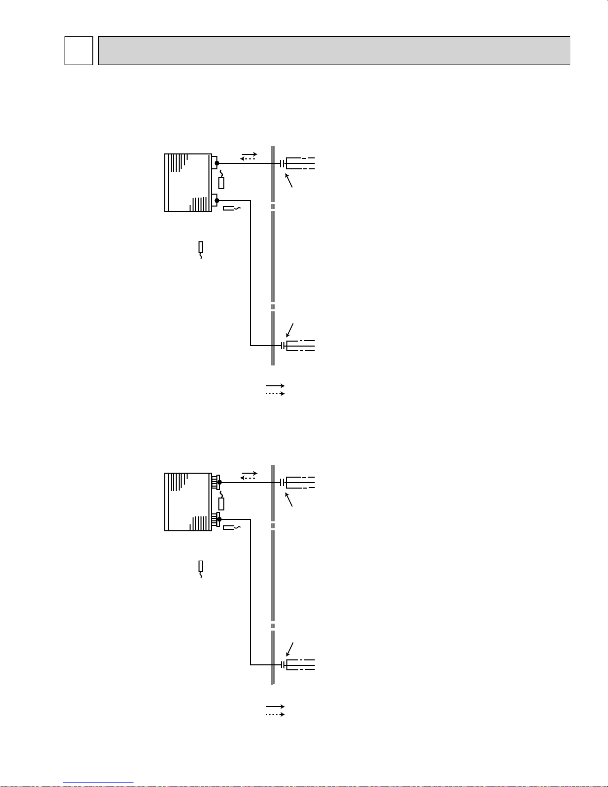
OBH548D
REFRIGERANT SYSTEM DIAGRAM
MSZ-GE06NA MSZ-GE09NA MSZ-GE12NA MSZ-GE15NA MSZ-GE18NA
MSY-GE09NA MSY-GE12NA MSY-GE15NA MSY-GE18NA
Refrigerant pipe ø3/8 (MSZ-GE06/09/12NA, MSY-GE09/12NA)
ø1/2 (MSZ-GE15/18NA, MSY-GE15/18NA)
(with heat insulator)
Indoor
heat
exchanger
Room temperature
thermistor
RT11
Indoor coil
thermistor
RT12 (main)
Indoor coil
thermistor
RT13 (sub)
Flared connection
Flared connection
Refrigerant pipe ø1/4
(with heat insulator)
Unit: inch
MSZ-GE24NA
MSY-GE24NA
Indoor
heat
exchanger
Indoor coil
thermistor
RT13 (sub)
Room temperature
thermistor
RT11
Indoor coil
thermistor
RT12 (main)
Refrigerant flow in cooling
Refrigerant flow in heating
Refrigerant pipe ø5/8
(with heat insulator)
Flared connection
Flared connection
Refrigerant pipe ø3/8
(with heat insulator)
Refrigerant flow in cooling
Refrigerant flow in heating
11
7
OBH548D
SERVICE FUNCTIONS
MSZ-GE06NA MSZ-GE09NA MSZ-GE12NA MSZ-GE15NA MSZ-GE18NA MSZ-GE24NA
MSY-GE09NA MSY-GE12NA MSY-GE15NA MSY-GE18NA MSY-GE24NA
7-1. TIMER SHORT MODE
For service, the set time can be shortened by bridging of JPG and JPS the indoor electronic control P.C. board.
The time will be shortened as follows. (Refer to 9-7.)
• The set time for the ON/OFF timer can be reduced to 1 second for each minutes.
• After the breaker is turned on, the time for starting the compressor, which normally takes 3 minuets, can be reduced to
3 seconds. Restarting the compressor, which takes 3 minuets, cannot be reduced.
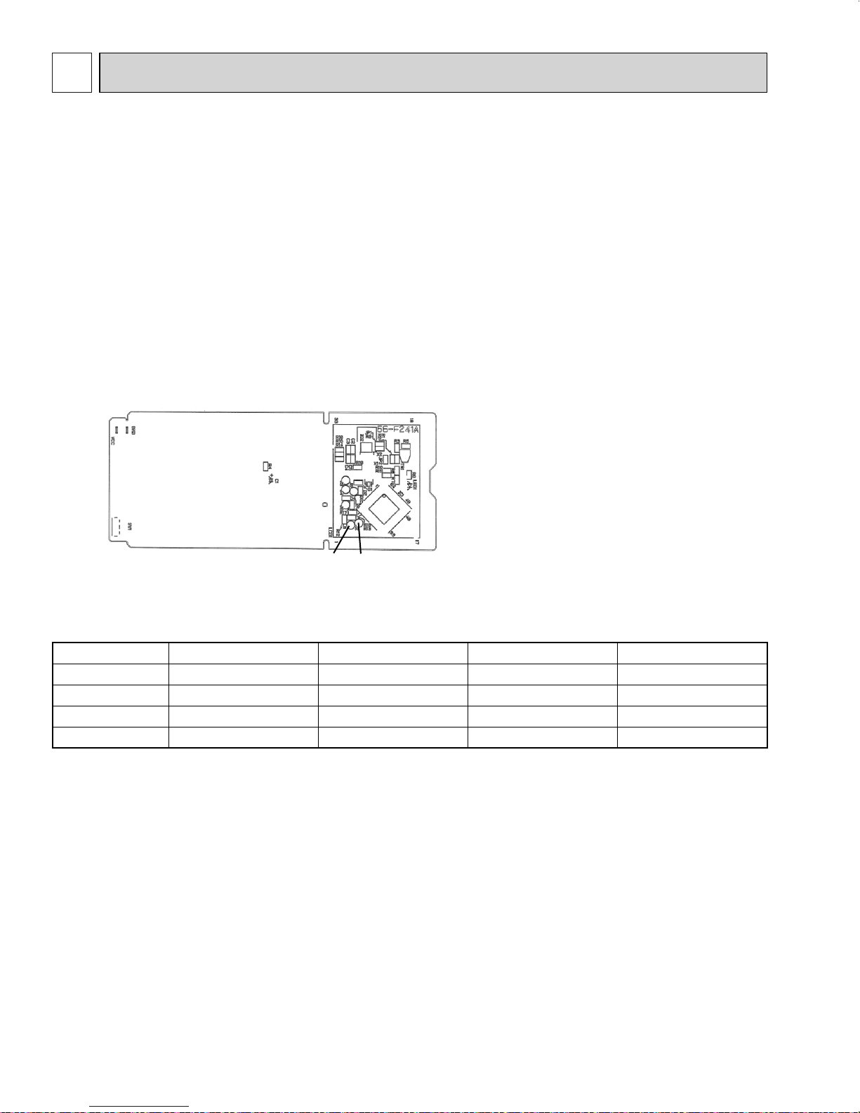
7-2. P.C. BOARD MODIFICATION FOR INDIVIDUAL OPERATION
A maximum of 4 indoor units with wireless remote controllers can be used in a room.
In this case, to operate each indoor unit individually by each remote controller, P.C. boards of remote controller must be
modified according to the number of the indoor unit.
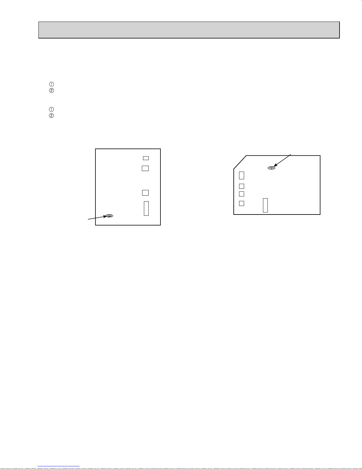
How to modify the remote controller P.C. board
Remove batteries before modification.
The board has a print as shown below:
NOTE: For modification, take out the batteries and
press the OPERATE/STOP (ON/OFF) button
twice or 3 times at first.
After finish modification, put back the batteries
then press the RESET button.
J1
J2
The P.C. board has the print “J1” and “J2”. Solder “J1” and “J2” according to the number of indoor unit as shown in Table 1.
After modification, press the RESET button.
Table 1
1 unit operation 2 units operation 3 units operation 4 units operation
No. 1 unit No modifi cation Same as at left Same as at left Same as at left
No. 2 unit — Solder J1 Same as at left Same as at left
No. 3 unit — — Solder J2 Same as at left
No. 4 unit — — — Solder both J1 and J2
How to set the remote controller exclusively for particular indoor unit
After you turn the breaker ON, the first remote controller that sends the signal to the indoor unit will be regarded as the remote
controller for the indoor unit.
The indoor unit will only accept the signal from the remote controller that has been assigned to the indoor unit once they are
set.
The setting will be cancelled if the breaker has turned OFF, or the power supply has shut down.
Please conduct the above setting once again after the power has been restored.
12
7-3. AUTO RESTART FUNCTION
OBH548D
When the indoor unit is controlled with the remote controller, the operation mode, the set temperature, and the fan speed
are memorized by the indoor electronic control P.C. board. “AUTO RESTART FUNCTION” automatically starts operation
in the same mode just before the shut-off of the main power.
Operation
If the main power has been cut, the operation settings remain.
After the power is restored, the unit restarts automatically according to the memory.
(However, it takes at least 3 minutes for the compressor to start running.)
How to disable “AUTO RESTART FUNCTION”
Turn OFF the main power of the unit.
Solder the Jumper wire JR07 on the indoor electronic control P.C. board. (Refer to 9-7.)
JR07
MSZ-GE06/09/12/15/18NA
MSY-GE09/12/15/18NA
Indoor electronic
control P.C. board
CN111CN112CN151CN10A
MSZ-GE24NA
MSY-GE24NA
CN112
CN 111
CN152
CN151
CN10A
JR07
Indoor electronic
control P.C. board
NOTE:
• The operation settings are memorized when 10 seconds have passed after the indoor unit was operated with the
remote controller.
• If main power is turned OFF or a power failure occurs while AUTO START/STOP timer is active, the timer setting is
cancelled.
• If the unit has been OFF with the remote controller before power failure, the auto restart function does not work as
the power button of the remote controller is OFF.
• To prevent breaker OFF due to the rush of starting current, systematize other home appliance not to turn ON at the
same time.
• When some air conditioners are connected to the same supply system, if they are operated before power failure, the
starting current of all the compressors may flow simultaneously at restart.
Therefore, the special counter-measures are required to prevent the main voltage-drop or the rush of the starting
current by adding to the system that allows the units to start one by one.
13
8
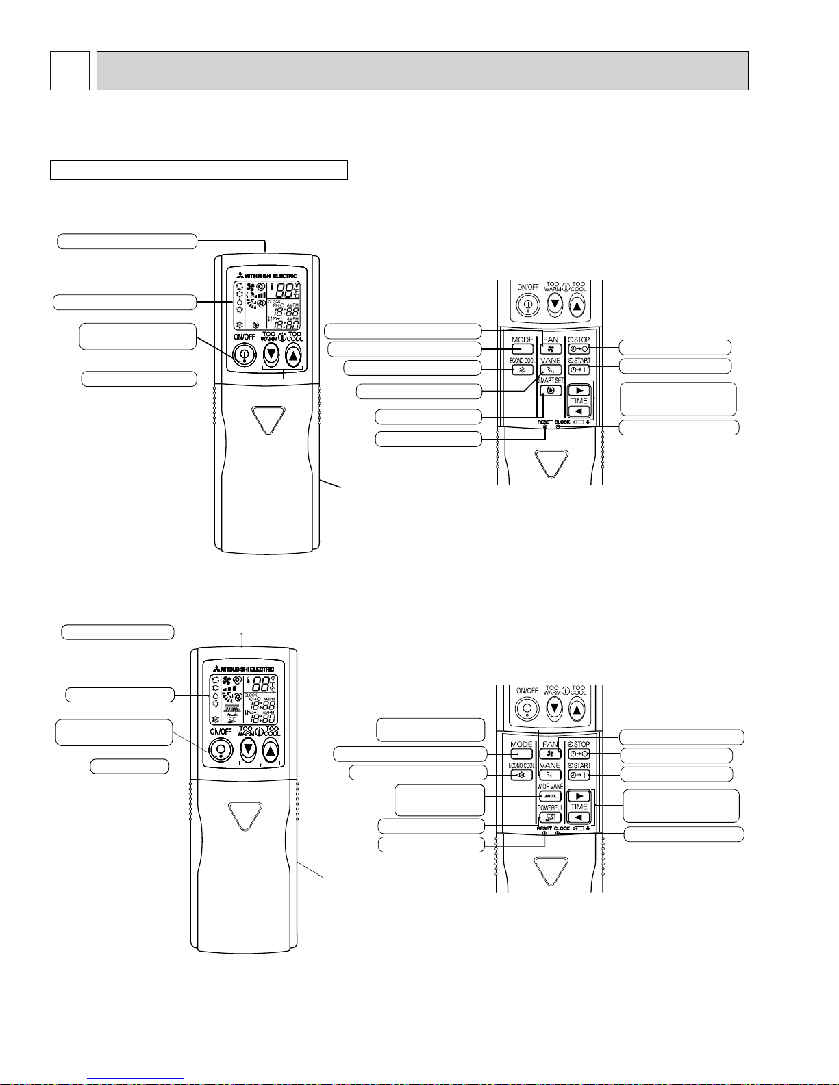
Signal transmitting section
Operation display section
Indication of
remote controller
model is on back
Temperature buttons
VANE CONTROL button
(Horizontal vane button)
WIDE VANE button
(Vertical vane button)
ON TIMER button
CLOCK SET button
TIME SET buttons
FORWARD button
BACKWARD button
OFF TIMER button
RESET button
POWERFUL button
OPERATE/STOP
(ON/OFF) button
FAN SPEED CONTROL button
OPERATION SELECT button
ECONO COOL button
OBH548D
MICROPROCESSOR CONTROL
MSZ-GE06NA MSZ-GE09NA MSZ-GE12NA MSZ-GE15NA MSZ-GE18NA MSZ-GE24NA
MSY-GE09NA MSY-GE12NA MSY-GE15NA MSY-GE18NA MSY-GE24NA
WIRELESS REMOTE CONTROLLER
E.g.: MSZ type
MSZ-GE06NA MSZ-GE09NA MSZ-GE12NA MSZ-GE15NA MSZ-GE18NA
MSY-GE09NA MSY-GE12NA MSY-GE15NA MSY-GE18NA
Signal transmitting section
Operation display section
OPERATE/STOP
(ON/OFF) button
Temperature buttons
FAN SPEED CONTROL button
OPERATION SELECT button
ECONO COOL button
VANE CONTROL button
SMART SET button
RESET button
Indication of
remote controller
model is on back
OFF TIMER button
ON TIMER button
TIME SET buttons
FORWARD button
BACKWARD button
CLOCK SET button
MSZ-GE24NA
MSY-GE24NA
NOTE: Last setting will be stored after the unit is turned OFF with the remote controller. Indoor unit receives the signal of the
remote controller with beeps.
14
INDOOR UNIT DISPLAY SECTION
OBH548D
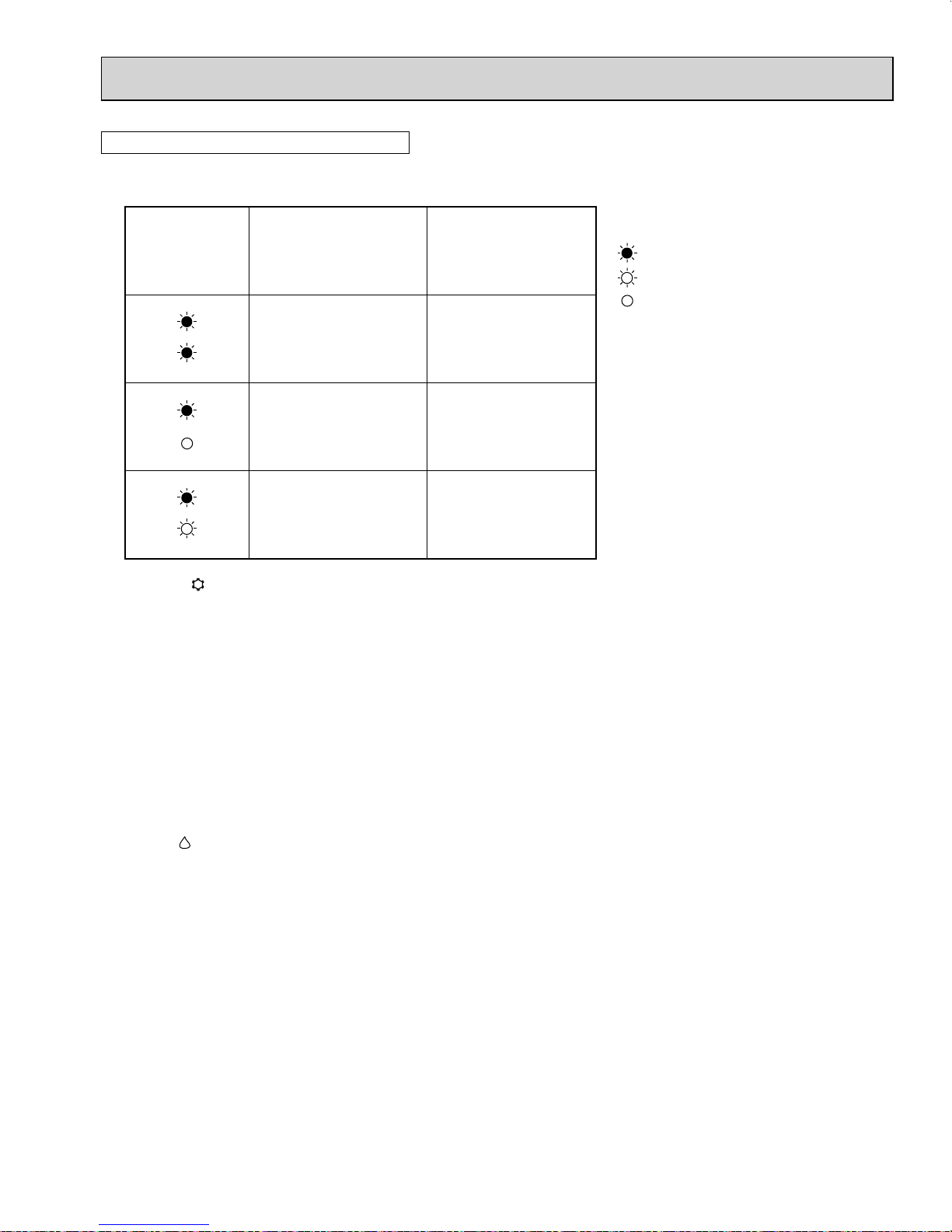
Operation Indicator lamp
The operation indicator at the right side of the indoor unit indicates the operation state.
• The following indication applies regardless of shape of the indication.
Indication Operation state Room temperature
The unit is operating to
reach the set temperature
The room temperature is
approaching the set temperature
Standby mode
(Only during multi system
operation)
8-1. COOL (
(1) Press OPERATE/STOP (ON/OFF) button.
OPERATION INDICATOR lamp of the indoor unit turns ON with a beep tone.
(2) Select COOL mode with OPERATION SELECT button.
(3) Press TEMPERATURE buttons (TOO WARM or TOO COOL button) to select the desired temperature.
The setting range is 61 ~ 88°F (16 ~ 31°C).
1. Coil frost prevention
The compressor operational frequency is controlled by the temperature of the indoor heat exchanger to prevent the coil from
frosting.
When the temperature of indoor heat exchanger becomes too low, the coil frost prevention mode works.
The indoor fan operates at the set speed and the compressor stops. This mode continues until the temperature of indoor
heat exchanger rises.
2. Low outside temperature operation
When the outside temperature is lower, low outside temperature operation starts, and the outdoor fan slows or stops.
) OPERATION
About 4°F(2°C) or more
away from set temperature
About 2 to 4°F(1 to 2°C)
from set temperature
-
Lighted
Blinking
Not lighted
8-2. DRY (
(1) Press OPERATE/STOP (ON/OFF) button.
OPERATION INDICATOR lamp of the indoor unit turns ON with a beep tone.
(2) Select DRY mode with OPERATION SELECT button.
(3) The set temperature is determined from the initial room temperature.
1. Coil frost prevention
Coil frost prevention works the same way as that in the COOL mode. (8-1.1.)
2. Low outside temperature operation
Low outside temperature operation works the same way as that in the COOL mode. (8-1.2.)
) OPERATION
15
 Loading...