

Mitsubishi Electric CMB-WM-V-AA, CMB-WM-V-AB, CMB-WM108V-AA, CMB-WM108V-AB, Model name CMB-WM1016V-AB Data Book
...Page 1

AIR CONDITIONING SYSTEMS
MODEL
CMB-WM-V-AA
CMB-WM-V-AB
EIo-1
Page 2

HBC controller
CMB-WM-V-AA, CMB-WM-V-AB (for YNW/YLM-Series)
I.HBC controller
1.SPECIFICATIONS ........................................................................................................................................... 2
2.EXTERNAL DIMENSIONS .............................................................................................................................. 6
3.CENTER OF GRAVITY ................................................................................................................................. 10
4.ELECTRICAL WIRING DIAGRAMS .............................................................................................................. 11
5.SOUND LEVELS ........................................................................................................................................... 15
5-1. Sound levels ......................................................................................................................................... 15
5-2. NC curves ............................................................................................................................................. 15
6.ELECTRICAL CHARACTERISTICS.............................................................................................................. 16
Indoor units
MEES17K102
EIo-1 1
Page 3
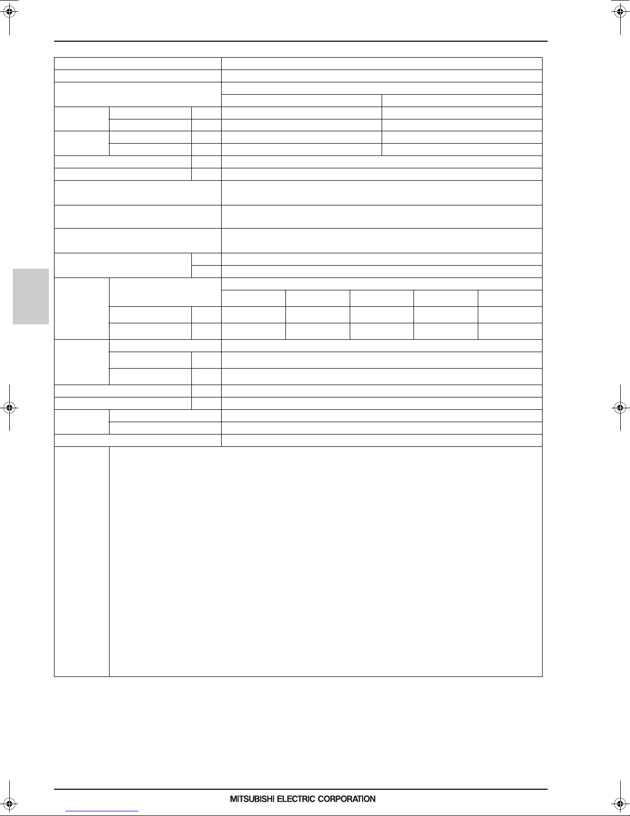
1. SPECIFICATIONS
I.HBC controller1. SPECIFICATIONS
Model name CMB-WM108V-AA
Number of branch 8
Power source 1-phase 220-230-240 V
50 Hz 60 Hz
Power input Cooling kW 0.45/0.46/0.47 0.45/0.46/0.47
(220/230/240) Heating kW 0.45/0.46/0.47 0.45/0.46/0.47
Current input Cooling A 2.89/2.83/2.79 2.89/2.83/2.79
(220/230/240) Heating A 2.89/2.83/2.79 2.89/2.83/2.79
Sound pressure level (measured in anecho ice room) dB <A> 41
Applicable temperature ra nge of installation site °C (D.B.) 0~32
External finish Galvanized steel plate
(Lower part drain pan: Pre-coated galvanized sheets + powder coating)
Connectable outdoor/heat source unit
Indoor unit capacity connectable to 1 branch
External dimension H x W x D
To outdoor/heat source unit
Refrigerant piping
diameter
Water piping
diameter
HBC controller
Field drain pipe size mm (in.) O.D. 32 (1-1/4)
Net weight kg (lbs) 86 (190) [96 (212) with water]
Standard
attachment
Optional parts
Note 1.Works not included:
High press. Pipe
Low press. Pipe
To Indoor unit
Inlet Pipe
Outlet Pipe
Document
Accessory Drain Connection pipe (with flexible hose and insulation)
Installation/foundation work, electrical connection work, duct work, insulation work, power source switch, and other items are not specified in this specifications.
2.The equipment is for R410A/R32 refrigerant.
3.Install this product in a location where noise (refrigerant noise) emitted by the unit will not disturb the neighbors.
(For use in quiet environments with low background noise, position the HBC CONTROLL ER at least 5 m away from any indoor units.)
4.Please install the HBC controller in a place where noise will not be an issue.
5.Please attach an expansion vessel (field supply).
6.Please use copper or plastic pipes for the water circuit. Do not use steel or stainless steel pipework.
Furthermore, when using copper pipewo rk use a non-oxidative brazing method.
Oxidation of the pipework will reduce the pump life.
7.When brazing the pipes, be sure to braze, after covering a wet cloth to the insulation pipes of the units in order to prevent it from burning and shrinking by heat.
8.Please install an air purge valve where air will gather in the water circuit.
9.Please install a pressure reducing valve and a strainer on the water supply to the HBC controller.
10.Please refer to the databook or the installation manual for the specified water quality.
11.This unit is not designed for outside installations.
12.Please always make water circulate or pull out the circulation water completely when not using it.
*Please do not use it as a drinking water.
13.Please do not use ground water and well water.
14.When installing the HBC unit in an environment which may drop below 0 °C, please add antifreez e to the circulating water.
(Refer to the databook and the installation manual).
15.R32 is flammable, and certain restrictions apply to the installation of units.
When installing new units, moving the existing units, or changing the layout of the room,
ensure that installation restrictions are observed.
For detail, refer to the section in the Databook on installation restrictions.
mm 300 x 1,520 x 630
in.
mm (in.)
O.D.
mm (in.)
O.D.
mm (in.)
I.D.
mm (in.)
I.D.
PURY-P200~500YLM-A(1)(-BS)/PURY -EP200~500YLM-A1(-BS)/PQRY-P200~500YLM -A2/A1
To P200
To M300
15.88 (5/8)
Brazed
19.05 (3/4)
Brazed
PURY-P200~500YNW-A(-BS)/PURY-EP200~500YNW-A(-BS)
PURY-M200~300YNW-A(-BS)/PURY- EM200~300YNW-A(-BS)
Model P80 or smaller
(Use optional joint pipe combing 2 branches when the total unit capacity excee ds P81)
11-13/16 x 59-7/8 x 24-13/16
Connectable outdoor/heat source unit capacity
To P250/300 To P350 To P400 for each To P450/500 for each
19.05 (3/4)
Brazed
22.2 (7/8)
Brazed
19.05 (3/4)
Brazed
28.58 (1-1/8)
Brazed
20 (3/4)
20 (3/4)
–
–
15.88 (5/8)
Brazed
19.05 (3/4)
Brazed
Indoor units
19.05 (3/4)
Brazed
22.2 (7/8)
Brazed
MEES17K102
EIo-1
2
Page 4
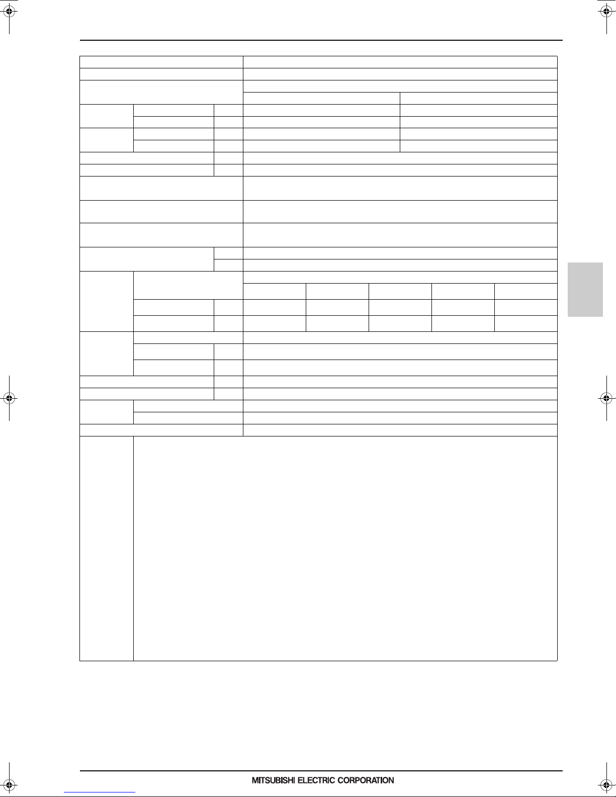
1. SPECIFICATIONS
Model name CMB-WM1016V-AA
Number of branch 16
Power source 1-phase 220-230-240 V
50 Hz 60 Hz
Power input Cooling kW 0.45/0.46/0.47 0.45/0.46 /0.47
(220/230/240) Heating kW 0.45/0.46/0.47 0.45/0.46/0.47
Current input Cooling A 2.89/2.83/2.79 2.89/2.83/2.79
(220/230/240) Heating A 2.89/2.83/2.79 2.89/2.83/2.79
Sound pressure level (measured in anechoice room) dB <A> 41
Applicable temperature range of installation site °C (D.B.) 0~32
External finish
Connectable outdoor/heat source unit
Indoor unit capacity connectable to 1 branch
External dimension H x W x D
To outdoor/heat source unit
Refrigerant piping
diameter
Water piping
diameter
Field drain pipe size mm (in.) O.D. 32 (1-1/4)
Net weight kg (lbs) 98 (217) [111 (245) with water]
Standard
attachment
Optional parts
Note 1.Works not included:
High press. Pipe
Low press. Pipe
To Indoor unit
Inlet Pipe
Outlet Pipe
Document –
Accessory Drain Connection pipe (with flexible hose and insulation)
Installation/foundation work, electrical connection work, duct work, insulation work, power source switch, and other items are not specified in this specifications.
2.The equipment is for R410A/R32 refrigerant.
3.Install this product in a location where noise (refrigerant noise) emitted by the un it will not disturb the neighbors.
(For use in quiet environments with low background noise, position the HBC CONTROLLER at least 5 m away from any indoor units.)
4.Please install the HBC controller in a place where noi se will not be an issue.
5.Please attach an expansion vessel (field supply).
6.Please use copper or plastic pipes for the water circuit. Do not use steel or stainless steel pipework.
Furthermore, when using copper pipework use a non-oxidative brazing method.
Oxidation of the pipework will reduce the pump life.
7.When brazing the pipes, be sure to braze, after covering a wet cloth to the insulation pipes of the units in order to prevent it from burning and shrinking by heat.
8.Please install an air purge valve where air will gather in the water circuit.
9.Please install a pressure reducing valve and a strainer on the water supply to the HBC controller.
10.Please refer to the databook or the installation manual for the specified water quality.
11.This unit is not designed for outside installations.
12.Please always make water circulate or pull out the circulation water completely wh en not using it.
*Please do not use it as a drinking water.
13.Please do not use ground water and well water.
14.When installing the HBC unit in an environment which may drop below 0 °C, please add antifreeze to the circulating water.
(Refer to the databook and the installation manual).
15.R32 is flammable, and certain restrictions apply to the installation of units.
When installing new units, moving the existing units, or changing the layout of the room,
ensure that installation restrictions are observed.
For detail, refer to the section in the Databook on installation restrictions.
mm 300 x 1,800 x 630
in.
To P200
mm (in.)
O.D.
mm (in.)
O.D.
mm (in.)
I.D.
mm (in.)
I.D.
To M300
15.88 (5/8)
Brazed
19.05 (3/4)
Brazed
(Lower part drain pan: Pre-coated galvanized sheets + powder coating)
PURY-P200~500YNW-A(-BS)/PURY-EP200~500YNW-A(-BS)
PURY-P200~500YLM-A(1)(-BS)/PURY -EP200~500YLM-A1(-BS)/PQRY-P200~500YLM-A2/A1
PURY-M200~300YNW-A(-BS)/PURY-EM200~300YNW-A(-BS)
(Use optional joint pipe combing 2 branches when the total unit capacity exceeds P81)
To P250/300 To P350 To P400 for each To P450/500 for each
19.05 (3/4)
Brazed
22.2 (7/8)
Brazed
Galvanized steel plate
Model P80 or smaller
11-13/16 x 70-7/8 x 24-13/16
Connectable outdoor/heat sou rce unit capacity
19.05 (3/4)
Brazed
28.58 (1-1/8)
Brazed
20 (3/4)
20 (3/4)
–
15.88 (5/8)
19.05 (3/4)
Brazed
Brazed
Indoor units
19.05 (3/4)
Brazed
22.2 (7/8)
Brazed
HBC controller
MEES17K102
EIo-1
3
Page 5
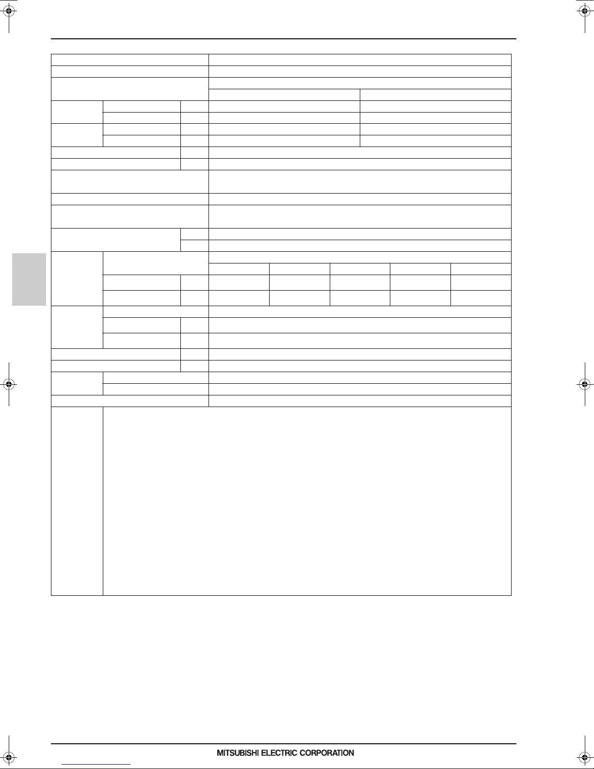
1. SPECIFICATIONS
Model name CMB-WM108V-AB
Number of branch 8
Power source 1-phase 220-230-240 V
50 Hz 60 Hz
Power input Cooling kW 0.01/0.01/0.01 0.01/0.01/0.01
(220/230/240) Heating kW 0.01/0.01/0.01 0.01/0.01/0.01
Current input Cooling A 0.05/0.05/0.05 0.05/0.05/0.05
(220/230/240) Heating A 0.05/0.05/0.05 0.05/0.05/0.05
Sound pressure level (measured in anecho ice room) dB <A> –
Applicable temperature ra nge of installation site °C (D.B.) 0~32
External finish Galvanized steel plate
(Lower part drain pan: Pre-coated galvanized sheets + powder coating)
Connectable outdoor/heat source unit –
Indoor unit capacity connectable to 1 branch
External dimension H x W x D
To outdoor/heat source unit
Refrigerant piping
diameter
Water piping
diameter
Field drain pipe size mm (in.) O.D. 32 (1-1/4)
HBC controller
Net weight kg (lbs) 44 (98) [49 (109) with water]
Standard
attachment
Optional parts
Note 1.Works not included:
High press. Pipe
Low press. Pipe
To Indoor unit
Inlet Pipe
Outlet Pipe
Document
Accessory Drain Connection pipe (with flexible hose and insulation)
Installation/foundation work, electrical connection work, duct work, insulation work, power source switch, and other items are not specified in this specifications.
2.The equipment is for water.
3.Install this product in a location where noise (refrigerant noise) emitted by the unit will not disturb the neighbors.
(For use in quiet environments with low b ackground noise, position the Sub HBC CONTROLLER at least 5 m away from any indoor units.)
4.Please install the Sub HBC controller in a place where noise will not be an issue.
5.Please attach an expansion vessel (field supply).
6.Please use copper or plastic pipes for the water circuit. Do not use steel or stainless steel pipework.
Furthermore, when using copper pipewo rk use a non-oxidative brazing method.
Oxidation of the pipework will reduce the pump life.
7.When brazing the pipes, be sure to braze, after covering a wet cloth to the insulation pipes of the units in order to prevent it from burning and shrinking by heat.
8.Please install an air purge valve where air will gather in the water circuit.
9.Please refer to the databook or the installation manual for the specified water quality.
10.This unit is not designed for outside installations.
11.Please always make water circulate or pull out the circulation water completely when not using it.
*Please do not use it as a drinking water.
12.Please do not use ground water and well water.
13.When installing the Sub HBC unit in an environment which may drop below 0 °C, please add antifreeze to the circul ating water.
(Refer to the databook and the installation manual).
14.Can't use singleness. (MAIN HBC CONTROLLER is necessary)
mm 300 x 1,520 x 630
in.
mm (in.)
O.D.
mm (in.)
O.D.
mm (in.)
I.D.
mm (in.)
I.D.
(Use optional joint pipe combing 2 branches when the total unit capacity excee ds P81)
Connectable outdoor/heat source unit capacity
–––––
–––––
–––––
Model P80 or smaller
11-13/16 x 59-7/8 x 24-13/16
20 (3/4)
20 (3/4)
–
–
Indoor units
MEES17K102
EIo-1
4
Page 6
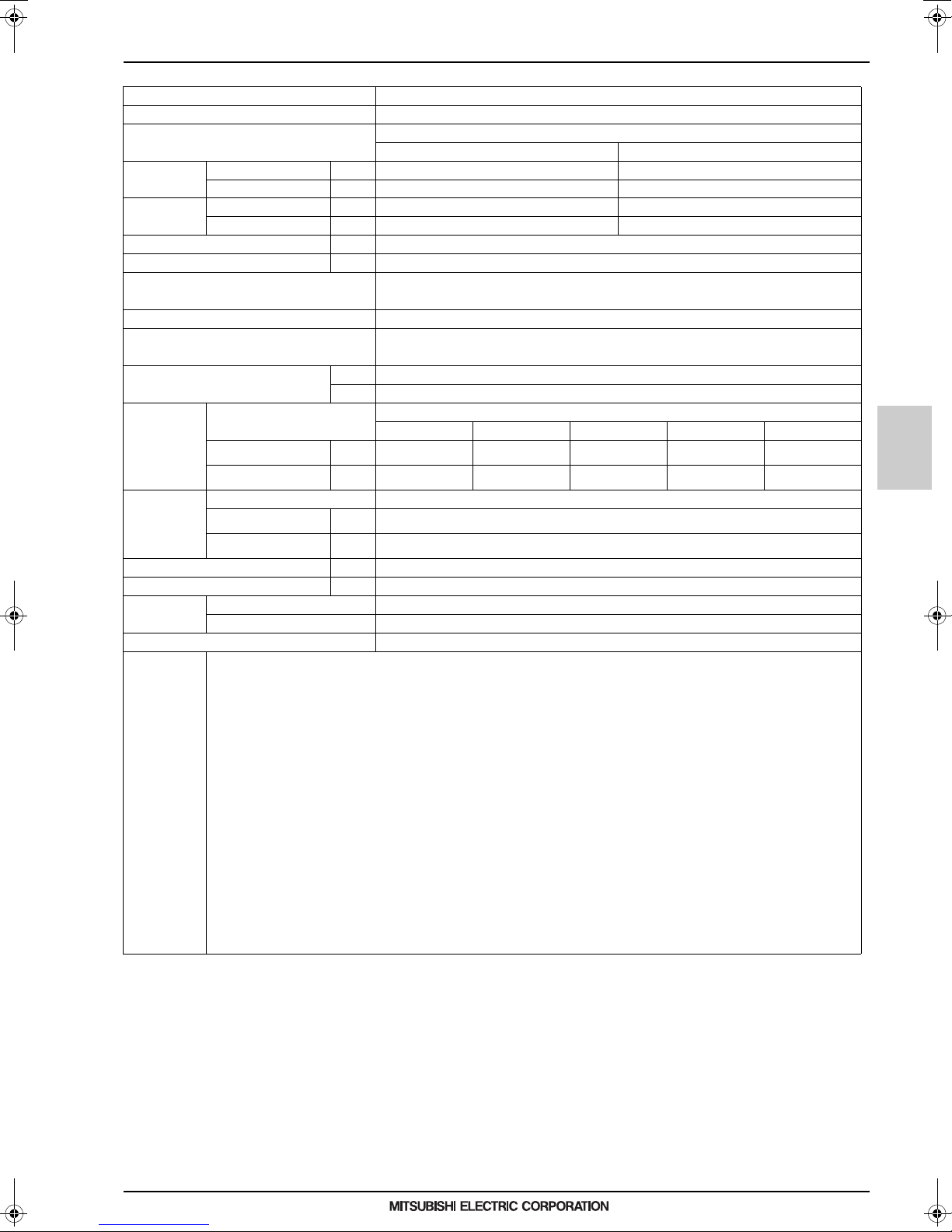
1. SPECIFICATIONS
Model name CMB-WM1016V-AB
Number of branch 16
Power source 1-phase 220-230-240 V
50 Hz 60 Hz
Power input Cooling kW 0.01/0.01/0.01 0.01/0.01 /0.01
(220/230/240) Heating kW 0.01/0.01/0.01 0.01/0.01/0.01
Current input Cooling A 0.05/0.05/0.05 0.05/0.05/0.05
(220/230/240) Heating A 0.05/0.05/0.05 0.05/0.05/0.05
Sound pressure level (measured in anechoice room) dB <A> –
Applicable temperature range of installation site °C (D.B.) 0~32
External finish
Connectable outdoor/heat source unit –
Indoor unit capacity connectable to 1 branch
External dimension H x W x D
To outdoor/heat source unit
Refrigerant piping
diameter
Water piping
diameter
Field drain pipe size mm (in.) O.D. 32 (1-1/4)
Net weight kg (lbs) 53 (117) [62 (137) with water]
Standard
attachment
Optional parts –
Note 1.Works not included:
High press. Pipe
Low press. Pipe
To Indoor unit
Inlet Pipe
Outlet Pipe
Document –
Accessory Drain Connection pipe (with flexible hose and insulation)
Installation/foundation work, electrical connection work, duct work, insulation work, power source switch, and other items are not specified in this specifications.
2.The equipment is for water.
3.Install this product in a location where noise (refrigerant noise) emitted by the un it will not disturb the neighbors.
(For use in quiet environments with low background noise, position the Sub HBC CONTROLLER at least 5 m away from any indoor units.)
4.Please install the Sub HBC controller in a place where noise will n ot be an issue.
5.Please attach an expansion vessel (field supply).
6.Please use copper or plastic pipes for the water circuit. Do not use steel or stainless steel pipework.
Furthermore, when using copper pipework use a non-oxidative brazing method.
Oxidation of the pipework will reduce the pump life.
7.When brazing the pipes, be sure to braze, after covering a wet cloth to the insulation pipes of the units in order to prevent it from burning and shrinking by heat.
8.Please install an air purge valve where air will gather in the water circuit.
9.Please refer to the databook or the installation manual for the specified water quality.
10.This unit is not designed for outside installations.
11.Please always make water circulate or pull out the circulation water completely wh en not using it.
*Please do not use it as a drinking water.
12.Please do not use ground water and well water.
13.When installing the Sub HBC unit in an environment which may drop below 0 °C, please add antifreeze to the circulating water.
(Refer to the databook and the installation manual).
14.Can't use singleness. (MAIN HBC CONTROLLER is necessary)
mm 300 x 1,520 x 630
in.
–––––
mm (in.)
O.D.
mm (in.)
O.D.
mm (in.)
I.D.
mm (in.)
I.D.
–––––
–––––
(Lower part drain pan: Pre-coated galvanized sheets + powder coating)
(Use optional joint pipe combing 2 branches when the total unit capacity exceeds P81)
Galvanized steel plate
Model P80 or smaller
11-13/16 x 59-7/8 x 24-13/16
Connectable outdoor/heat sou rce unit capacity
20 (3/4)
20 (3/4)
Indoor units
HBC controller
MEES17K102
EIo-1
5
Page 7

2. EXTERNAL DIMENSIONS
2. EXTERNAL DIMENSIONS
Indoor units
CMB-WM108V-AA
14
30
12
Y
Control box
1379
(Lifting bolt pitch)
HBC controller
Detail of Y section
543
540 90
Cutting point
(Lifting bolt pitch)
93
Z
93
31
43
51
93
200
3
Detail of Z section
224
216
157
44
272
286
1321
1391
Connection pipe from SUB HBC
[Field supply]
ø22.0(use attachment pipe)
Connection pipe to SUB HBC
[Field supply]
ø22.0(use attachment pipe)
ø22.0(use attachment pipe)
[Field supply]
Connection pipe from indoor unit
1520
70X7=490
412
ø19.05<Brazed>
Connection pipe of
outdoor/heat source unit
(High pressure)
ø22.2<Brazed>
Connection pipe of
outdoor/heat source unit
(Low pressure)
181
151
103
73
154
84
70
12345678
74
148
153
180
Unit : mm
[Field supply]
ø22.0(use attachment pipe)
Connection pipe to SUB HBC
[Field supply]
ø22.0(use attachment pipe)
Connection pipe from SUB HBC
Connection pipe to indoor unit
ø22.0(use attachment pipe)
[Field supply]
70X7=490
70
447
Water pipe(Inlet)
[Field supply]
ø22.0(use attachment pipe)
Water pipe(EXP.Tank)
[Field supply]
ø22.0(use attachment pipe)
300
Band(Accessory)
prepare in the field.
(Please give attention not to occupy service space by
letting ducts and pipes through.)
·Drain hose I.D.32(1-1/4")·····················1pc.
·Hose band········································1pc.
·Tie band···········································1pc.
·Wrench············································1pc.
<Accessories>
2. Take notice of service space as follows.
Note1. Suspension bolt(ø10),washer(M10),and nut(M10)
X
276
ø31
Detail of X section
Drain hose I.D.32(1-1/4") (Accessory)
160300
450
450
160
Access
door
Access
door
450
(700)
250
space
Service
Connection pipe from MAIN HBC
ø15.88<Brazed>
Drain piping VP-25 Connection
200
100120
Service space
Service space
Service space
MEES17K102
EIo-1
6
Page 8

2. EXTERNAL DIMENSIONS
Indoor units
CMB-WM1016V-AA
14
30
12
Detail of Y section
543
Y
Control box
1659
(Lifting bolt pitch)
Cutting point
(Lifting bolt pitch)
93
Z
93
Detail of Z section
1601
Connection pipe from SUB HBC
Connection pipe to SUB HBC
ø22.0(use attachment pipe)
[Field supply]
ø22.0(use attachment pipe)
[Field supply]
Connection pipe from indoor unit
1800
1671
181
151
103
73
[Field supply]
ø22.0(use attachment pipe)
Connection pipe from SUB HBC
154
70X15=1050412
70
1 2 3 4 5 6 7 8 9 10111213141516
84
Unit : mm
Connection pipe to SUB HBC
[Field supply]
ø22.0(use attachment pipe)
[Field supply]
ø22.0(use attachment pipe)
Connection pipe to indoor unit
ø22.0(use attachment pipe)
[Field supply]
70X15=1050
70
447
HBC controller
540 90
93
300
Band(Accessory)
prepare in the field.
(Please give attention not to occupy service space by
letting ducts and pipes through.)
2. Take notice of service space as follows.
·Drain hose I.D.32(1-1/4")·····················1pc.
·Hose band········································1pc.
·Tie band···········································1pc.
·Wrench············································1pc.
<Accessories>
Note1. Suspension bolt(ø10),washer(M10),and nut(M10)
286
272
224
216
157
31
43
44
51
200
3
276
X
ø31
Detail of X section
Drain hose I.D.32(1-1/4") (Accessory)
(High pressure)
ø22.2<Brazed>
Connection pipe of
outdoor/heat source unit
(Low pressure)
450
300300300
450450
Access
door
Access
door
74
148
153
Connection pipe of
outdoor/heat source unit
ø19.05<Brazed>
(700)
250
space
Service
180
[Field supply]
ø22.0(use attachment pipe)
Water pipe(EXP.Tank)
Connection pipe from MAIN HBC
ø15.88<Brazed>
Drain piping VP-25 Connection
200
100120
Service space
Service space
Water pipe(Inlet)
[Field supply]
ø22.0(use attachment pipe)
Service space
MEES17K102
EIo-1
7
Page 9

2. EXTERNAL DIMENSIONS
Indoor units
CMB-WM108V-AB
14
30
12
Y
1379
(Lifting bolt pitch)
HBC controller
Detail of Y section
Control box
Cutting point
(Lifting bolt pitch)
543
540 90
Detail of Z section
Z
149
93
44
200
52
3
219
1520
154
84
Connection pipe from indoor unit
ø22.0(use attachment pipe)
[Field supply]
70X7=490
70
12345678
290
73
103
141
171
Connection pipe to indoor unit
ø22.0(use attachment pipe)
[Field supply]
70X7=490
70
325
Unit : mm
300
Band(Accessory)
prepare in the field.
(Please give attention not to occupy service space by
letting ducts and pipes through.)
·Drain hose I.D.32(1-1/4")·····················1pc.
·Hose band········································1pc.
<Accessories>
2. Take notice of service space as follows.
·Tie band···········································1pc.
Note1. Suspension bolt(ø10),washer(M10),and nut(M10)
X
276
ø31
Detail of X section
Drain hose I.D.32(1-1/4") (Accessory)
Connection pipe to MAIN HBC
160300160 450450
[Field supply]
ø22.0(use attachment pipe)
[Field supply]
ø22.0(use attachment pipe)
Connection pipe from MAIN HBC
(700)
450
250
Access
door
Access
door
space
Service
[Field supply]
ø22.0(use attachment pipe)
Connection pipe to MAIN HBC
[Field supply]
ø22.0(use attachment pipe)
Connection pipe from MAIN HBC
Drain piping VP-25 Connection
200
100120
Service space
Service space
Service space
MEES17K102
EIo-1
8
Page 10

2. EXTERNAL DIMENSIONS
Indoor units
CMB-WM1016V-AB
14
30
12
Detail of Y section
Y
1379
Control box
(Lifting bolt pitch)
Cutting point
(Lifting bolt pitch)
543
540 90
Detail of Z section
Z
149
93
44
200
52
3
219
1520
154
Connection pipe from indoor unit
ø22.0(use attachment pipe)
[Field supply]
84
70X15=1050
70
1 2 3 4 5 6 7 8 9 10111213141516
290
73
103
141
171
Connection pipe to indoor unit
ø22.0(use attachment pipe)
[Field supply]
70X15=1050
70
325
Unit : mm
HBC controller
300
Band(Accessory)
prepare in the field.
(Please give attention not to occupy service space by
letting ducts and pipes through.)
2. Take notice of service space as follows.
·Drain hose I.D.32(1-1/4")·····················1pc.
·Hose band········································1pc.
·Tie band···········································1pc.
Note1. Suspension bolt(ø10),washer(M10),and nut(M10)
<Accessories>
Drain hose I.D.32(1-1/4") (Accessory)
X
ø31
Detail of X section
276
[Field supply]
ø22.0(use attachment pipe)
Connection pipe to MAIN HBC
[Field supply]
ø22.0(use attachment pipe)
Connection pipe from MAIN HBC
(700)
250
450
160300160 450450
Access
door
Access
door
space
Service
[Field supply]
ø22.0(use attachment pipe)
Connection pipe to MAIN HBC
[Field supply]
ø22.0(use attachment pipe)
Connection pipe from MAIN HBC
Drain piping VP-25 Connection
200
100120
Service space
Service space
Service space
MEES17K102
EIo-1
9
Page 11

3. CENTER OF GRAVITY
CMB-WM108, 1016V-AA
CMB-WM108, 1016V-AB
xz
y
543 A
Center of gravity
Indoor unit branching point
A (mm)
x (mm)
y (mm)
z (mm)
CMB-WM108V-AA
1379
680
145
285
CMB-WM1016V-AA
1659
825
145
285
CMB-WM108 V-AB
1379
610
145
270
CMB-WM1016V-AB
1379
680
145
270
3. CENTER OF GRAVITY
Indoor units
HBC controller
MEES17K102
EIo-1
10
Page 12

4. ELECTRICAL WIRING DIAGRAMS
4. ELECTRICAL WIRING DIAGRAMS
CMB-WM108V-AA
Name
Fuse AC250V 6.3A F
Solenoid valve
F001
SV1
Symbol
Name
AC reactor
Thermister sensor
TH11~16,TH32~35,
ACL
Symbol
(Symbol explanation)
TH32
t°
Function setting connector
4 way valve
Pump
Valve blockFSFloat switch
21S4Ma,21S4Mb
WP1,WP2
VB3a~h
Z
Terminal block
(for power source)
Terminal block
Expansion valve
LEV1~3
TH31a~h
TH33
(for Transmission)
Pressure sensor
PS1,PS3
TB01
TB02
TH31g
TH16
TH15
t°
t°t°t°
1
1
2
2
3
4
5
CN509(Blue)
CN511(Red)
SW1:0
SW2:0
Never connect power line to it.
Control Board are as follows.
2. The initial set values of switch on
NOTE:1. TB02 is transmission terminal block.
TH31f
TH31e
TH31h
t°
3
4
CN508(Red)
1
t°
2
t°
3
4
TH35
t°
1
2
3
CN506(Blue)
1
2
3
4
4
5
667
CN505
dotted line are field work.
3. The wirings to TB01 and TB02 shown in
TH31a
TH34
t°
t°
1
2
5
7
CN503(Blue)
Indoor units
TH12
TH11
CN501
TH31c
TH31d
TH13
TH14
t°t°t°
t°t°t°
1
2
3
4
5
6
HBC controller
TH31b
t°
3
4
5
6
Transmission Line
Indoor/outdoor
TB02
M1
M2
S(SHIELD)
1
1
2
2
3
3
4
4
5
5
6
1
C004 C006
SV1
3
X006
CN504(Yellow)
M
LEV2
1
(Red)
CN003
ZNR001
ZNR002
6
CN502(Red)
111
333222
444
555
666
(Yellow) (Green)
(Blue)
CNLEV1 CNLEV2 CNLEV3
M
LEV1
21S4Mb 21S4Ma
653
7
6
5
X002
X003
4
3
(Blue)
CN001
2
1
2
1
CN002
(Green)
CNAC
F001
250VAC
6.3A F
(Red)
UU
DSA001
CN005
1
355371
ACL
PULL BOX
TO NEXT INDOOR UNIT
L
N
TB01
X
~220V-240V
POWER SUPPLY
50Hz/60Hz
BREAKER(16A)
FUSE(16A)
43213215432132154321321543213215
LD1:CPU in
operation
CN216 CN215
LD1:CPU in
operation
CN214 CN213
LD1:CPU in
operation
LD1:CPU in
operation
CN210 CN209 CN212 CN211
432132154321321
CN207CN208
LD1:CPU in
operation
5
CN205
LD1:CPU in
operation
CN206
5
4321321
(Red)(Red) (Yellow)(Yellow) (Red) (Red) (Yellow) (Yellow) (Red) (Red)
CN203
LD1:CPU in
operation
CN204
CN201
32132145
CN202
LD1:CPU in
operation
Detail of X section
MMMMMMMM
VB3a VB3b VB3c VB3d VB3e VB3f VB3g VB3h
11 22 33
PS1PS3
FS
Z
ON
ON
CN103
CN101
(Blue)
(Red)
CN512CN513
LED1
10 12345678910
123456789
CN101
CN401
1 1
2 2
3 3
CN201
32 1
11 24 45 56 6
SW3
SW4
(Red)
CN003
(Red)
(Red)
1
10
ON
CN001
CN002
3
1
Power Board
CN510
1
2
34
SWP2SWP1 SWP3
SW5
12345678
(Green)
(Blue)
1
CN518
SW1SW2
1
2
1
2
3
4
5
6
7
CN204
2
CN203
(Red)
3
4
5
123
(Blue)
CN514
Control Board
M
LEV3
WP1
WP2
11
22
33
55
77
99
CN006
(Yellow)
L001
C003 C005
C002 C007
MEES17K102
EIo-1
11
Page 13

4. ELECTRICAL WIRING DIAGRAMS
CMB-WM1016V-AA
Name
Fuse AC250V 6.3A F
Solenoid valve
4 way valve
Pump
Valve block
Function setting connector
Float switch
F001
SV1
21S4Ma,21S4Mb
WP1,WP2
VB3a~p
Z
Symbol
Name
AC reactor
FS
Pressure sensor
Thermister sensor
Expansion valve
Terminal block
(for power source)
Terminal block
(for Transmission)
SW1:0
SW2:0
Control Board are as follows.
Never connect power line to it.
2.The initial set values of switch on
dotted line are field work.
3.The wirings to TB01 and TB02 shown in
Indoor units
ACL
LEV1~3
TH11~16,TH32~35,
TH31a~p
Symbol
(Symbol explanation)
PS1PS3
FS
HBC controller
Indoor/outdoor
Transmission Line
TB02
M1
M2
S(SHIELD)
PS1,PS3
TB01
TB02
TH31h
TH31g
TH16
TH33
TH15
TH32
t°t°t°
t°
1
1
2
2
3
3
4
4
5
CN508(Red)
CN509(Blue)
CN511(Red)
1
2
3
CN512
CN510
1
2
3
4
5
1
2
3
CN518
4
110
SW1SW2
LED1
1
SW3
123456789
10 10
SW4
123456789
O
CN101
(Red)
(Red) (Red)
CN201 CN003
3
SWP2SWP1 SWP3
SW5
12345678
1
2
CN001
(Green)
1
2
3
4
5
(Blue)
CN002
6
7
1
CN203
(Red)
CN204
Power Board
2
3
11
22
Z
ON
ON
1
2
3
CN513
CN401
1 1
2 2
3 3
(Blue)
CN103
CN101
(Red)
32 1
11 24 45 56 6
NOTE:1.TB02 is transmission terminal block.
TH31b
TH31f
TH31e
TH35
TH31k
TH31l
t°
t°t°t°
t°t°t°
CN505
1
1
2
2
3
3
4
4
5
667
CN506(Blue)
(Blue)
CN514
Control Board
WP1
WP2
33
55
77
99
L001
TH31a
TH34
TH31i
TH31j
t°
t°
t°t°t°
1
1
2
2
3
3
4
4
5
5
7
6
CN503(Blue)
1
2
3
4
5
6
CN504(Yellow)
1
2
3
4
CN507
CN516
11
22
33
(Red)
CN515
M
M
LEV2
LEV3
SV1
21S4Mb 21S4Ma
1
3
1
CN006
(Red)
(Yellow)
CN003
X002
X006
X003
ZNR001
UU
ZNR002
C004 C006
C003 C005
C002 C007
TH12
TH11
TH31c
TH31d
TH13
TH14
t°t°t°
t°t°t°t°t°
CN501
1
2
3
4
5
6
1
2
3
4
5
6
CN502(Red)
111
3
444
555
666
33222
(Yellow) (Green)
(Blue)
CNLEV1 CNLEV2 CNLEV3
M
LEV1
653
7
6
5
4
3
(Blue)
CN001
2
1
2
1
CN002
(Green)
CNAC
F001
250VAC
6.3A F
(Red)
DSA001
CN005
1
355371
ACL
TH31m
TH31n
t°
TO NEXT INDOOR UNIT
TH31p
TH31o
t°
LD1:CPU in
operation
LD1:CPU in
operation
443322113322115544332211332211554321321
CN216 CN218CN215 CN217
LD1:CPU in
operation
CN214 CN220CN213 CN219
LD1:CPU in
operation
LD1:CPU in
operation
LD1:CPU in
operation
LD1:CPU in
operation
LD1:CPU in
operation
LD1:CPU in
operation
LD1:CPU in
operation
CN210 CN209 CN212 CN211
CN205
CN206
CN203
CN204
CN207CN208
CN201
CN202
54
5
321321
54321321
4321321
Detail of X section
5
5
4321321
(Red)(Red) (Yellow)(Yellow) (Red) (Red) (Yellow) (Yellow) (Red) (Yellow)(Red) (Yellow)
32145
321
87654321
LD1:CPU in
operation
87654321
X
~220V-240V
POWER SUPPLY
50Hz/60Hz
FUSE(16A) BREAKER(16A)
PULL BOX
TB01
L
N
LD1:CPU in
operation
LD1:CPU in
operation
LD1:CPU in
operation
LD1:CPU in
operation
LD1:CPU in
operation
CN805(Red)
87654321
CN804
87654321
CN803(Yellow) CN806(Yellow)
87654321
CN802(Red)
8765432
CN801
1
MEES17K102
MM MMMMMMMMMMM MMM
VB3k VB3a VB3bVB3l VB3cVB3m VB3dVB3n VB3eVB3o VB3fVB3p VB3g VB3jVB3h VB3i
EIo-1
12
Page 14

4. ELECTRICAL WIRING DIAGRAMS
CMB-WM108V-AB
Name
Valve block
Float switch
Thermister sensor
TH31a~h,TH32,TH33
Symbol
VB3a~h
FS
(Symbol explanation)
Fuse AC250V 6.3A F
Terminal block
TB01
Function setting connector
(for power source)
Terminal block
(for Transmission)
TB02
F001
Z
SW1:0
SW2:0
Never connect power line to it.
2. The initial set values of switch on
dotted line are field work.
Control Board are as follows.
3. The wirings to TB01 and TB02 shown in
NOTE:1. TB02 is transmission terminal block.
Indoor units
Indoor/outdoor
Transmission Line
TB02
M1
M2
S(SHIELD)
TH31b
TH31f
TH31e
TH31h
ON ON
CN103
CN101
(Blue)
(Red)
CN401
32 1
11 2
LED1
SW3
SW4
12345678910 12345678910
CN101
(Red)
TH31g
1
CN509(Blue)
CN510
1234
110
SWP2SWP1 SWP3
SW5
ON
12345678
CN001
(Green)
3
1
Power Board
2
1
CN518
SW1SW2
1
2
3
4
2
3
123
t°t°t°t°t°
1
2
3
CN508(Red)
4
5
(Blue)
CN514
4
Control Board
L001
TH33
TH32
t°
t°
FS
Z
TH31a
t°
t°
1
2
3
4
5
CN503(Blue)
1
2
3
4
5
66
CN504(Yellow)
ZNR001
UU
ZNR002
C004 C006
C003 C005
C002 C007
TH31c
TH31d
t°
2
1
CN002
(Green)
(Red)
CNAC
F001
250VAC
6.3A F
DSA001
CN005
1
355371
POWER SUPPLY
PULL BOX
TO NEXT INDOOR UNIT
L
N
TB01
X
~220V-240V
50Hz/60Hz
FUSE(16A) BREAKER(16A)
43213215432132154321321543213215
LD1:CPU in
operation
CN216 CN215
LD1:CPU in
operation
CN214 CN213
LD1:CPU in
operation
LD1:CPU in
operation
CN210 CN209 CN212 CN211
432132154321321
CN207CN208
LD1:CPU in
operation
5
CN205
LD1:CPU in
operation
CN206
5
4321321
(Red)(Red) (Yellow)(Yellow) (Red) (Red) (Yellow) (Yellow) (Red) (Red)
CN203
LD1:CPU in
operation
CN204
CN201
32132145
CN202
LD1:CPU in
operation
HBC controller
Detail of X section
MMMMMMMM
VB3a VB3b VB3c VB3d VB3e VB3f VB3g VB3h
MEES17K102
EIo-1
13
Page 15

4. ELECTRICAL WIRING DIAGRAMS
CMB-WM1016V-AB
Name
Valve block
Function setting connector
Float switch
Thermister sensor
Terminal block
(for power source)
Terminal block
(for Transmission)
Fuse AC250V 6.3A F
SW1:0
SW2:0
Never connect powerline to it.
ControlBoardare asfollows.
dotted line are field work.
3.The wirings to TB01 and TB02 shown in
TH31b
TH31a
TH31j
°
°
t°t
Z
FS
TH31a~p,TH32,TH33
Symbol
(Symbol explanation)
TH32
°
TH33
t°t
TB01
VB3a~p
TH31g
°
TB02
TH31h
F001
TH31e
t°t°t
2.The initial set valuesof switch on
NOTE:1.TB02 is transmissionterminal block.
TH31k
TH31l
TH31f
°
t
TH31i
°
t°t
t°t
TH31c
°
t
TH31d
°
t
TH31m
°
t
TH31n
t°t°t
TH31p
Indoor units
TH31o
°
2
2
3
4
1
CN509(Blue)
CN510
3
4
2
1
FS
1
2
3
4
CN518
110
SW1SW2
LED1
Z
HBC controller
Indoor/outdoor
Transmission Line
TB02
M1
M2
S(SHIELD)
SW3
SWP2SWP1 SWP3
123456789 10
ON
SW4
SW5
123456789 1010
12345678
ON
ON
1
2
CN001
(Green)
CN101
1
3
(Red)
CN401
3
4
1
CN508(Red)
5
1
2
3
(Blue)
CN514
3
4
5
667
2
1
CN506(Blue)
Control Board
1
CN505
Power Board
(Blue)
CN103
L001
CN101
(Red)
32 1
11 2
2
3
3
4
4
5
5
7
6
1
2
CN503(Blue)
LD1:CPU in
operation
3
4
5
6
2
1
CN504(Yellow)
CN507
1
2
3
4
LD1:CPU in
operation
44332211332211554 43 32 21 13 32 21 15 54321321
CN216 CN218CN215 CN217
LD1:CPU in
operation
CN516
11
22
33
(Red)
CN515
X
~220V-240V
POWER SUPPLY
50Hz/60Hz
FUSE(16A) BREAKER(16A)
PULL BOX
2
1
CN002
(Green)
(Red)
CNAC
F001
250VAC
6.3A F
ZNR001
UU
ZNR002
C004 C006
C003 C005
C002 C007
DSA001
CN005
1
355371
TO NEXT INDOOR UNIT
TB01
L
N
87654321
LD1:CPU in
operation
87654321
CN805(Red)
LD1:CPU in
operation
87654321
CN804
LD1:CPU in
operation
87654321
CN803(Yellow) CN806(Yellow)
LD1:CPU in
operation
87654321
CN802(Red)
LD1:CPU in
operation
8765432
CN801
1
LD1:CPU in
operation
CN214 CN220CN213 CN219
LD1:CPU in
operation
54321321
LD1:CPU in
operation
5
CN210 CN209 CN212 CN211
LD1:CPU in
operation
54321321
4321321
CN207CN208
LD1:CPU in
operation
5
CN205
LD1:CPU in
operation
CN206
5
4321321
(Red)(Red) (Yellow)(Yellow) (Red) (Red) (Yellow) (Yellow) (Red) (Yellow)(Red) (Yellow)
CN203
CN204
LD1:CPU in
operation
32145
CN201
321
CN202
LD1:CPU in
operation
Detail of X section
MEES17K102
MM MMMMMMMMMMM MMM
VB3k VB3a VB3bVB3l VB3cVB3m VB3dVB3n VB3eVB3o VB3fVB3p VB3g VB3jVB3h VB3i
EIo-1
14
Page 16

5. SOUND LEVELS
5. SOUND LEVELS
5-1. Sound levels
(Measured point)
CMB-WM108V-AA
CMB-WM1016V-AA
1.5m
Measurement location
Measured in anechoic room.
*
5-2. NC curves
CMB-WM108V-AA,CMB-WM1016V-AA
Power Source: 230V, 50Hz
70.0
65.0
60.0
55.0
50.0
45.0
40.0
35.0
30.0
25.0
20.0
Approximate minimum
audible limit on
15.0
continuous noise
Octave band pressure level (dB) 0dB=20μPa
10.0
63 125 250 500 1k 2k 4k 8k
Octave band center frequencies (Hz)
Indoor units
HBC controller
NC-60
NC-50
NC-40
NC-30
NC-20
MEES17K102
EIo-1
15
Page 17

6. ELECTRICAL CHARACTERISTICS
6. ELECTRICAL CHARACTERISTICS
Symbols: MCA: Max. Circuit Amps, MFA: Max. Fuse Amps, RLA: Rated Load Amps
HBC controller
CMB-WM108V-AA
CMB-WM1016V-AA
CMB-WM108V-AB
CMB-WM1016V-AB
Hz Volts Range+-10% MCA(A) MFA(A)
220
50/60
230 2.83
240 2.79
220
50/60
230 0.05
240 0.05
Power supply
Max.: 264V
Min.: 198V
Max.: 264V
Min.: 198V
Indoor units
RLA(A)
2.89
3.49 15
0.05
0.06 15
HBC controller
MEES17K102
EIo-1
16
Page 18

Warning
■
Do not use refrigerant other than the type indicated in the manuals provided with the unit and on the nameplate.
- Doing so may cause the unit or pipes to burst, or result in explosion or fire during use, repair, or at the time of disposal of the unit.
- It may also be in violation of applicable laws.
- MITSUBISHI ELECTRIC CORPORATION cannot be held responsible for malfunctions or accidents resulting from the use of the wrong
type of refrigerant.
■
Our air conditioning equipment and heat pumps contain a fluorinated greenhouse gas, R410A/R32.
MEES17K102
New publication effective Mar. 2018
Specifications subject to change without notice
 Loading...