

Page 1
Page 2

Page 3

MELDAS is a registered trademark of Mitsubishi Electric Corporation.
Other company and product names that appear in this manual are trademarks or registered
trademarks of the respective companies.
Page 4

Page 5
Introduction
This manual is an instruction manual for NAVI LATHE for 700/70 (hereafter NAVI LATHE).
This manual explains how to operate NAVI LATHE, so read this manual thoroughly before
use. Be sure to study "Precautions for Safety" on the next page and use the system safely.
Details described in this manual
CAUTION
For items described as "Restrictions" or "Usable State" in this manual, the instruction manual
issued by the machine tool builder takes precedence over this manual.
Items not described in this manual must be interpreted as "not possible".
This manual is written on the assumption that all option functions are added. Confirm with the
specifications issued by the machine tool builder before starting to use.
Refer to the Instruction Manual issued by each machine tool builder for details on each
machine tool.
Some screens and functions may differ depending on the NC system (or its version), and
some functions may not be possible. Please confirm the specifications before use.
Refer to the following documents.
MITSUBISHI CNC 700/70 Series Instruction Manual ....................................IB-1500042
MITSUBISHI CNC 700/70 Series Setup Manual ...........................................IB-1500124
MITSUBISHI CNC 700/70 Series Programming Manual (Lathe System) .....IB-1500057
Page 6

Page 7
Precautions for Safety
Always read the specifications issued by the machine tool builder, this manual, related
manuals and attached documents before operation or programming to ensure correct use.
Understand the NAVI LATHE, safety items and cautions before using the system.
This manual ranks the safety precautions into "DANGER", "WARNING" and "CAUTION".
DANGER
When the user may be subject to imminent fatalities or major
injuries if handling is mistaken.
WARN ING
When the user may be subject to fatalities or major injuries if
handling is mistaken.
CAUTION
When the user may be subject to bodily injury or when property
damage may occur if handling is mistaken.
Note that even items ranked as "
CAUTION", may lead to serious consequences depending
on the situation. In any case, important information that must always be observed is described.
DANGER
Not applicable in this manual.
WARNING
1. Items related to operation
If the operation start position is set in a block which is in the middle of the program and
the program is started, the program before the set block is not executed. Please
confirm that G and F modal and coordinate values are appropriate. If there are
coordinate system shift commands or M, S, T and B commands before the block set as
the start position, carry out the required commands using the MDI, etc. If the program is
run from the set block without carrying out these operations, there is a danger of
interference with the machine or of machine operation at an unexpected speed, which
may result in breakage of tools or machine tool or may cause damage to the operators.
Under the constant surface speed control (during G96 modal), if the axis targeted for
the constant surface speed control moves toward the spindle center, the spindle
rotation speed will increase and may exceed the allowable speed of the workpiece or
chuck, etc. In this case, the workpiece, etc. may jump out during machining, which may
result in breakage of tools or machine tool or may cause damage to the operators.
Page 8
1. Items related to product and manual
For items described as "Restrictions" or "Usable State" in this manual, the instruction
manual issued by the machine tool builder takes precedence over this manual.
Items not described in this manual must be interpreted as "not possible".
This manual is written on the assumption that all option functions are added. Confirm
with the specifications issued by the machine tool builder before starting use.
Refer to the Instruction Manual issued by each machine tool builder for details on
each machine tool.
Some screens and functions may differ depending on the NC system (or its version),
and some functions may not be possible. Please confirm the specifications before
use.
2. Items related to installation and assembly
Ground the signal cables to ensure stable system operation. Also ground the NC unit
main frame, power distribution panel and machine to one point, so they all have the
same potential.
3. Items related to preparation before use
Always set the stored stroke limit. Failure to set this could result in collision with the
machine end.
Always turn the power OFF before connecting/disconnecting the I/O device cable.
Failure to do so could damage the I/O device and NC unit.
CAUTION
4. Items related to screen operation
NAVI LATHE uses the following variables in order to operate the NC program.
NC program mode Variables used by NAVI LATHE
User macro mode #150 to #197
MTB macro mode #450 to #497
When NC program mode is user macro mode, do not use common variables (#150 to
#197). If those variables are written over, malfunction will be resulted. If mistakenly
written them over, turn the NC power OFF after securing your safety. When the power
is turned ON again, the system recovers the data. NC program mode is specified on
the Preferences screen.
When either "TOOL REG No." or "CYCLE" is input in each machining process screen,
the cutting speed and feedrate are automatically determined using the data in the tool
file screen and the cutting condition file screen. Note that the cutting speed and
feedrate of each process determined once will not be changed by changing the data in
the tool file screen and the cutting condition file screen.
(Continued on next page)
Page 9
5. Items related to operation
Stay out of the moveable range of the machine during automatic operation. During
rotation, keep hands, feet and face away from the spindle.
Carry out dry operation before actually machining, and confirm the machining program,
tool offset and workpiece coordinate system offset.
If the operation start position is set from a block in the program and the program is
started, the program before the set block is not executed. If there are coordinate
system shift commands or M, S, T, and B commands before the block set as the
starting position, carry out the required commands using the MDI, etc. There is a
danger of interference with the machine if the operation is started from the set starting
position block without carrying out these operations.
Program so the mirror image function is turned ON/OFF at the mirror image center.
The mirror image center will deviate if the function is turned ON/OFF at a position
other than the mirror image center.
6. Items related to faults and abnormalities
If the battery low warning is issued, save the machining programs, tool data and
parameters in an input/output device, and then replace the battery. When the battery
alarm is issued, the machining programs, tool data and parameters may be destroyed.
Reload the data after replacing the battery.
If the axis overruns or emits an abnormal noise, immediately press the emergency
stop button and stop the axis movement.
CAUTION
(Continued from previous page)
(Continued on next page)
Page 10
7. Items related to maintenance
Incorrect connections may damage the devices, so connect the cables to the
specified connectors.
Do not apply voltages other than those indicated according to specification on the
connector. Doing so may lead to destruction or damage.
Do not connect or disconnect the connection cables between each unit while the
power is ON.
Do not connect or disconnect the PCBs while the power is ON.
Do not connect the cable by pulling on the cable wire.
Do not short circuit, charge, overheat, incinerate or disassemble the battery.
Dispose the spent battery according to local laws.
Dispose the spent cooling fan according to local laws.
Do not replace the control unit while the power is ON.
Do not replace the operation panel I/O unit while the power is ON.
Do not replace the control section power supply PCB while the power is ON.
Do not replace the expansion PCB while the power is ON.
Do not replace the memory cassette while the power is ON.
Do not replace the cooling fan while the power is ON.
Do not replace the battery while the power is ON.
Be careful that metal cutting chips, etc., do not come into contact with the connector
contacts of the memory cassette.
Do not replace the high-speed program server unit while the power is ON.
CAUTION
(Continued from previous page)
Page 11

Disposal
(Note) This symbol mark is for EU countries only.
This symbol mark is according to the directive 2006/66/EC Article 20 Information for endusers and Annex II.
Your MITSUBISHI ELECTRIC product is designed and manufactured with high quality materials and
components which can be recycled and/or reused.
This symbol means that batteries and accumulators, at their end-of-life, should be disposed of
separately from your household waste.
If a chemical symbol is printed beneath the symbol shown above, this chemical symbol means that the
battery or accumulator contains a heavy metal at a certain concentration. This will be indicated as
follows:
Hg: mercury (0,0005%), Cd: cadmium (0,002%), Pb: lead (0,004%)
In the European Union there are separate collection systems for used batteries and accumulators.
Please, dispose of batteries and accumulators correctly at your local community waste collection/
recycling centre.
Please, help us to conserve the environment we live in!
Page 12

Page 13

Contents
1. OUTLINE .....................................................................................................................1
1.1 System Outline............................................................................................................1
1.2 Input Procedures.........................................................................................................3
1.3 Screen Configuration...................................................................................................4
1.4 Starting NAVI LATHE..................................................................................................5
1.5 Setting up NAVI LATHE ..............................................................................................6
2. FUNCTIONS OF DISPLAY AREA...............................................................................8
2.1 LIST VIEW Area..........................................................................................................9
2.2 OPERATION VIEW Area...........................................................................................11
2.3 Setting Area...............................................................................................................12
2.4 Message Area ...........................................................................................................12
2.5 Menu Display Area....................................................................................................12
3. BASIC OPERATIONS................................................................................................13
3.1 Changing Active View................................................................................................13
3.2 Changing Screen.......................................................................................................13
3.3 Setting Data...............................................................................................................15
3.4 Switching Windows....................................................................................................18
3.5 Switching Selection Tags ..........................................................................................18
3.6 Inputting Operations..................................................................................................19
4. SCREEN SPECIFICATIONS.....................................................................................20
4.1 Starting NAVI LATHE................................................................................................20
4.2 Screen Related to the Program.................................................................................21
4.2.1 Program Edit Screen ..................................................................................21
4.3 Screens Related to the Process Edit Functions........................................................26
4.3.1 Process List Screen....................................................................................26
4.3.2 Operating Process......................................................................................27
4.3.3 Process Mode Selection Screen.................................................................33
4.3.4 Initial Condition Setting Screen................................................................... 37
4.3.5 Turning Process..........................................................................................40
4.3.6 Copy Cut Process.......................................................................................46
4.3.7 Threading Screen.......................................................................................49
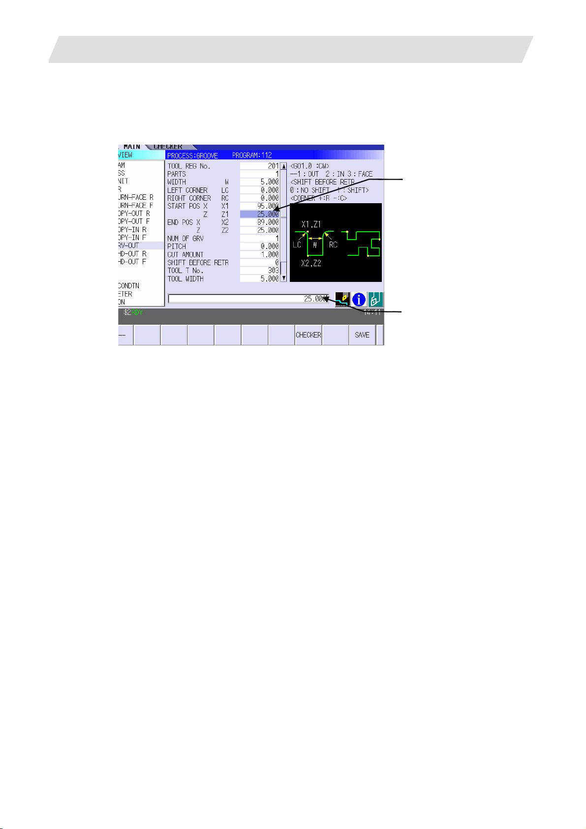
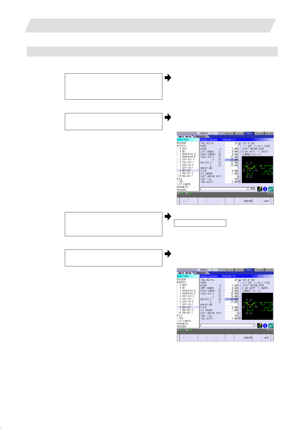
4.3.8 Grooving Screen.........................................................................................53
4.3.9 Trapezoidal Grooving Screen.....................................................................56
4.3.10 Hole Drilling Screen..................................................................................59
4.3.11 EIA Screen................................................................................................61
4.3.12 Milling Hole Drilling Screen.......................................................................62
4.3.13 Keyway Cutting Screen ............................................................................75
4.3.14 Contour Cutting Screen............................................................................81
4.4 Screens Related to File Editing.................................................................................90
4.4.1 Tool File Screen for Turning.......................................................................90
4.4.2 Tool File Screen for Milling.........................................................................95
4.4.3 Cutting Condition File Screen for Turning...................................................97
4.4.4 Cutting Condition File Screen for Milling...................................................101
Page 14

4.5 Screen Related to the Parameters..........................................................................103
4.5.1 Parameter Screen.....................................................................................103
4.5.1.1 Parameters for Turning................................................................103
4.5.1.2 Parameters for Milling..................................................................107
4.5.2 PREFERENCE Screen.............................................................................110
4.6 Screen Related to the Version.................................................................................112
4.6.1 Version Screen.........................................................................................112
4.7 Program Checker Screen........................................................................................113
4.8 Guidance Function ..................................................................................................122
4.8.1 Tool Guidance Screen..............................................................................123
4.8.1.1 Tool Guidance for Turning...........................................................123
4.8.1.2 Tool Guidance for Milling.............................................................125
5. PROGRAM SPECIFICATIONS................................................................................126
5.1 NC Program.............................................................................................................127
5.1.1 Output Method for NC Program................................................................127
5.1.2 Restrictions...............................................................................................131
5.2 File Program............................................................................................................133
5.3 Parameter Program.................................................................................................133
5.4 Macro Program........................................................................................................134
6. RESTRICTIONS FOR CNC FUNCTION SPECIFICATIONS...................................135
7. ALARM MESSAGE..................................................................................................139
7.1 Error Message.........................................................................................................139
7.2 Operation Message.................................................................................................142
APPENDIX 1. VARIABLES USED IN NAVI LATHE.....................................................143
APPENDIX 2. PROGRAMMING EXAMPLE 1 (TURNING) .........................................146
Appendix 2.1 Machining Drawing..................................................................................146
Appendix 2.2 Process Table..........................................................................................147
Appendix 2.3 Condition Setting.....................................................................................148
Appendix 2.4 Creating Program....................................................................................149
APPENDIX 3. PROGRAMMING EXAMPLE 2 (MILLING) ...........................................156
Appendix 3.1 Machining Drawing..................................................................................156
Appendix 3.2 Process Table..........................................................................................157
Appendix 3.3 Condition Setting.....................................................................................158
Appendix 3.4 Creating Program....................................................................................159
Page 15
1. OUTLINE
1. OUTLINE
1.1 System Outline
This manual is an instruction manual for NAVI LATHE for 700/70 (hereafter NAVI LATHE).
The part program for the turning center is created with the NAVI LATHE.
NAVI LATHE provides the turning function and the milling function.
(1) The following machining processes can be edited.
Turning Processes
• Turning (Outer dia., inner dia., front face)
• Copy cutting (Outer dia., inner dia., front face)
• Threading (Outer dia., inner dia., front face)
• Grooving (Outer dia., inner dia., front face)
• Trapezoidal grooving (Outer dia., inner dia., front face)
• Hole drilling (Drilling, deep-hole drilling, step, tapping)
• EIA
Milling Processes
• Milling hole drilling (Drilling, deep-hole drilling, boring, tapping)
• Keyway cutting (Front face, outer surface, side surface)
• Contour cutting (Front face, outer surface, side surface)
(Note) Milling interporation specifications are required to edit the milling processes.
1.1 System Outline
(2) The tool file and the cutting condition file are provided and the cutting conditions for each process are
determined automatically.
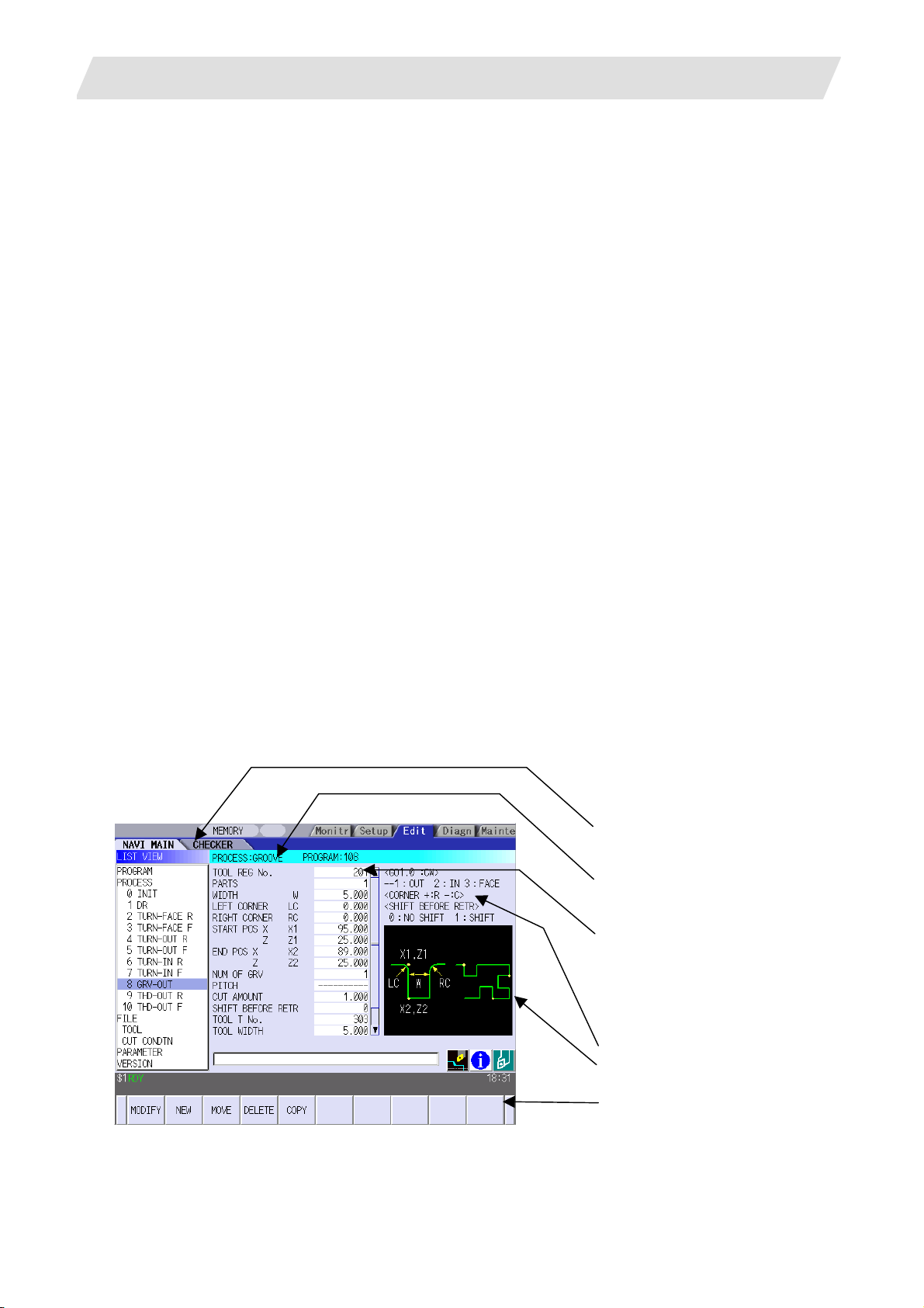
(3) The operation screen consists of the LIST VIEW area and the OPERATION VIEW area. In the LIST
VIEW area, the whole part program can be always viewed. In the OPERATION VIEW area, there are the
guide drawings related to the input items, and the data can be easily input by using these guide
drawings.
[LIST VIEW area]
The object of the NAVI LATHE is
selected.
[OPERATION VIEW area]
The screen is displayed
corresponding to the object selected
in the LIST VIEW.
[Cutting conditions automatically
determined]
Upon tool registration No. entry, the
cutting conditions for each process
are automatically determined based
on the tool file and cutting condition
file.
[Help]
[Guide drawing]
[Menu keys]
- 1 -
Page 16

1. OUTLINE
1.1 System Outline
(4) Program Checker enables the machining shape of a part program to be graphically traced. With this
function, errors in input data can be detected at an earlier stage.
(5) Guidance function provides an operator with error recovery information.
(6) Part program is a macro-program-based NC program. Commands can be added between processes
from the edit screen of the standard MITSUBISHI CNC 700/70 Series.
(7) The macro program mentioned above can be customized by the machine tool builder.
- 2 -
Page 17
1. OUTLINE
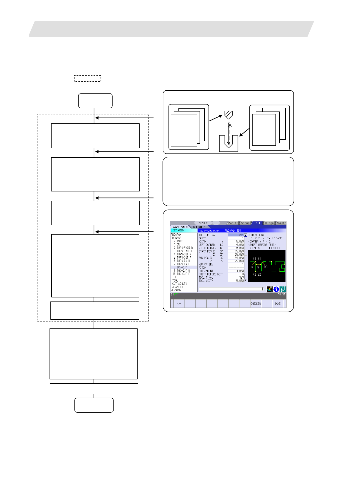
1.2 Input Procedures
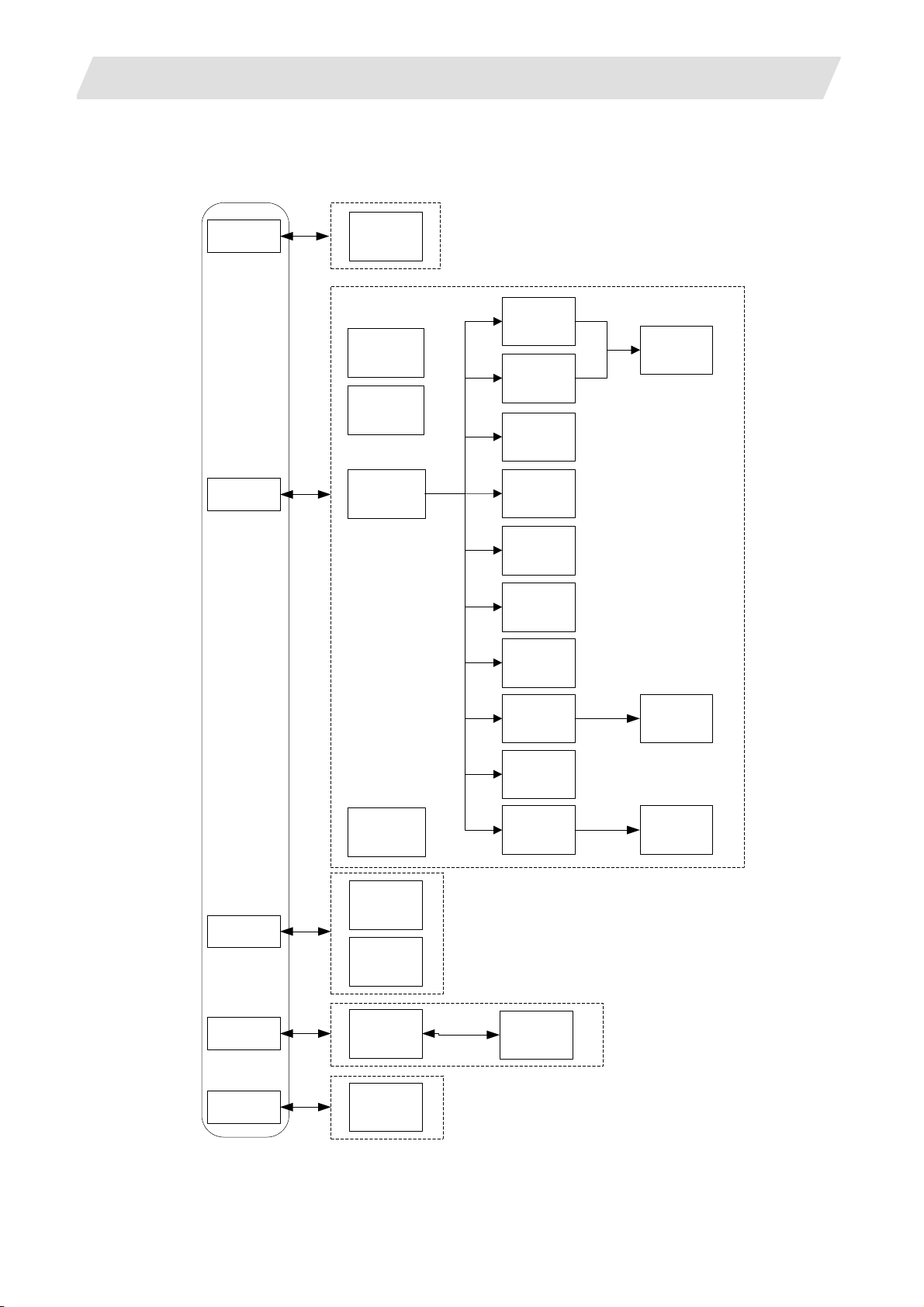
The input procedure for the NAVI LATHE is shown below.
The part is operated on
the NAVI LATHE's screen.
Supplements
1.2 Input Procedures
Start
File edition
Tool file
Cutting condition file
Parameter setting
Parameter file
(The parameter setting is valid
even if the parameter is set after
editing the NC program)
NC program selection
Newly create
Read out
Process editing:
Initial conditions
Process mode selection
Process data input
Turning / Copy cutting /
Threading / Grooving /
Trapezoidal grooving /
Hole drilling / EIA /
Milling hole drilling /
Keyway cutting / Contour cutting
Tool file
(Tool registration No. 10 1 -)
No.
No.
direction
99
1
No.
No.
No.
direction
Tool leng. offset
Tool leng. offset
Tool leng. offset
Tool diam. offset
Tool diam. offset
Spindle rotation
Spindle rotation
:
Cut condition file
(Work registration No.1 to 8)
Parameter setting
• M0 output
• Maximum number of spindle rotations
• Clearance
• Tool return position
• Common parameters for threading process
• Common parameters for grooving process
• Common parameters for hole drilling process
Process editing
Material
Tool applicable
Material
:
rotation rate
Tool applicable
:
rotation rate
:
8
1
Program check
Program Checker is used.
Program check
(Note) Set the tool
compensation amount and
workpiece coordinate system
offset to perform Program
Check. This function is realized
by using the 700/70 Series
graphic check functio n .
NC program operation
END
- 3 -
Page 18
1. OUTLINE
1.3 Screen Configuration
The screen configuration for the NAVI LATHE is shown below.
Program
Program
editing
screen
Process list
screen
Initial
condition
setting screen
Turning
screen
Copycutting
screen
Threading
screen
1.3 Screen Configuration
Process
pattern
screen
Process
File
Process mode
selection
screen
(For a new process,
select a process from
the process mode.)
Program
checker
Tool file
screen
Cutting
condition
file screen
Grooving
screen
Trapezoidal
grooving
screen
Hole drilling
screen
EIA screen
Milling
hole drilling
screen
Keyway
cutting
screen
Contour
cutting
screen
Process
pattern
screen
Process
pattern
screen
Parameter
Version
Parameter
screen
Version
screen
Preference
screen
- 4 -
Page 19
1. OUTLINE
Screen name Details
Program editing screen NC program is newly created and read out, etc.
Process list screen Tool information and cutting conditions for each process of a
Process mode selection
screen
Initial conditions setting
screen
Turning screen Various parameters for turning process are input.
Turning pattern screen The machining patterns for turning process are input.
Copy cutting screen Various parameters for copy cutting process are input.
Copy cutting pattern
screen
Threading screen Various parameters for threading process are input.
Grooving screen Various parameters for grooving process are input.
Trapezoidal grooving
screen
Hole drilling screen Various parameters for hole drilling process are input.
EIA screen The EIA process is input.
Milling hole drilling
screen
Milling hole drilling
pattern screen
Keyway cutting screen Various parameters for keyway cutting process are input.
Contour cutting screen Various parameters for contour cutting process are input.
Contour cutting pattern
screen
Tool file screen The tool data by each tool is registered.
Cutting condition file
screen
Parameter screen The parameters for a NC program are set.
Preference screen The system is set up.
Version screen The version data of the NAVI LATHE is displayed.
Program checker The machining shape of a NC program is graphically
1.4 Starting NAVI LATHE
1.3 Screen Configuration
NC program are listed.
The process mode (turning process, etc.) is selected.
The initial conditions for a NC program are set.
Machining patterns for copy cutting process are input.
Various parameters for trapezoidal grooving process are
input.
Various parameters for milling hole drilling process are input.
The machining patterns for milling hole drilling process are
input.
The machining patterns for contour cutting process are input.
The cutting conditions (cutting speed, feedrate) by each
process are input, corresponding to tip material. Also, the
cutting conditions (speed rate) by each process are input,
corresponding to workpiece material.
displayed.
Select
function, then the lathe menu to display NAVI LATHE screen.
EDIT
Program edit screen is displayed once when the power is turned ON. Then, whatever the screen
previously selected with NAVI LATHE is displayed thereafter.
- 5 -
Page 20

1. OUTLINE
1.5 Setting up NAVI LATHE
1.5 Setting up NAVI LATHE
Part program output from NAVI LATHE is a macro-program-based NC program. Thus, macro programs
have to be registered in the NC system in advance. Also, the destinations where NC programs or NAVI
LATHE's reference files are saved, as well as the unit for data input, have to be specified prior to NAVI
LATHE operations.
NAVI LATHE setup items
Item Details Standard value
PATH
PROGRAM
PATH
PARAMETER
MACRO Macro program mode
UNIT Unit for data input
Path to the folder in which NC program is saved. MEM:/
Path to the folder in which tool file, cutting condition file
and parameter file are saved.
1: User macro mode
2: MTB macro mode
1: inch
2: mm
In 700 Series:
D:/NCFILE/NAVI
In 70 Series:
MEM:/
1 (User Macro)
2 (mm)
- 6 -
Page 21
1. OUTLINE
1.5 Setting up NAVI LATHE
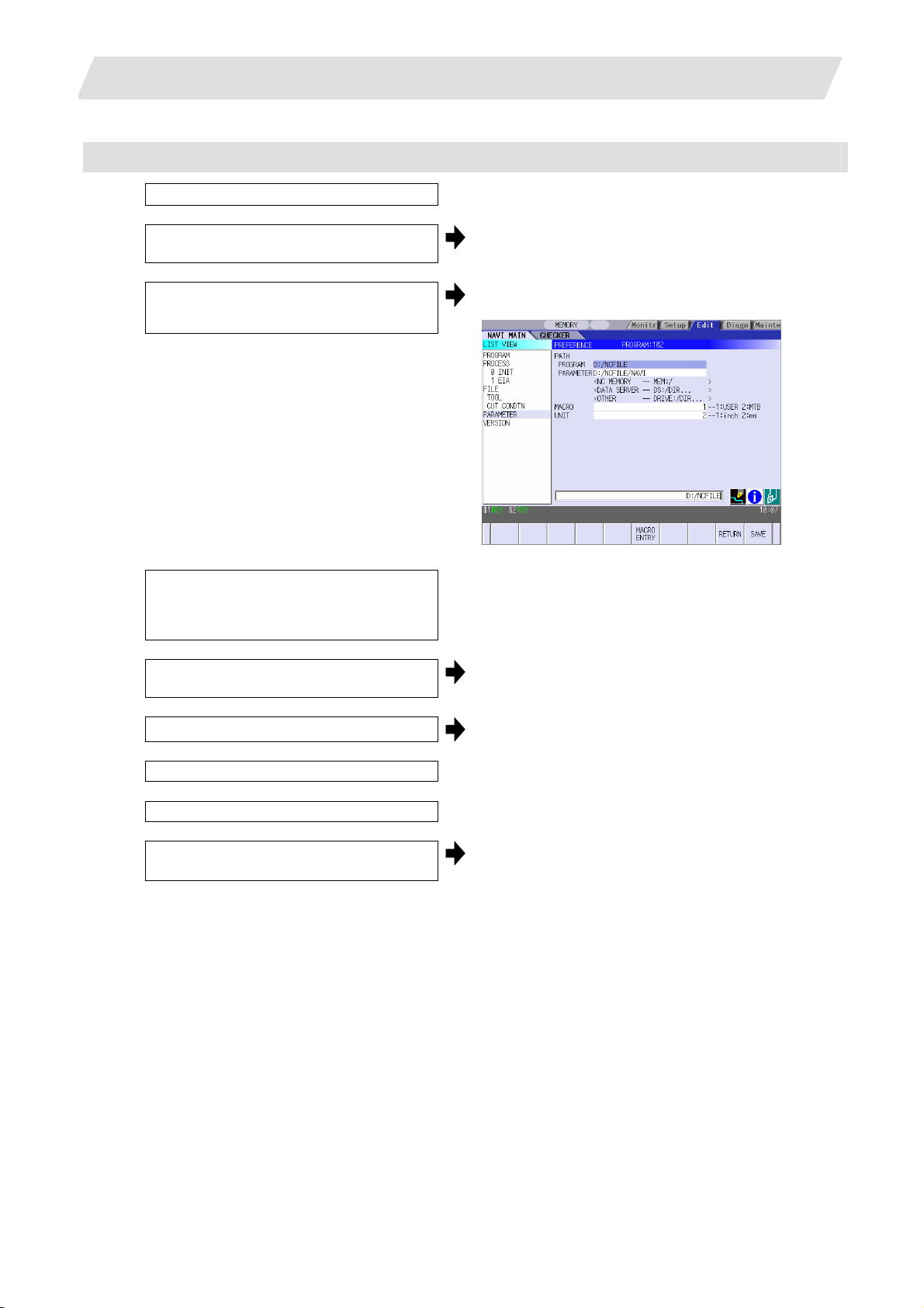
NAVI LATHE setup procedures
(1) Open PARAMETER screen.
(2) Set "999 MAINTE" to 1. [PREFERENCE] menu is displayed.
(3) Press [PREFERENCE] menu.
PREFERENCE screen is displayed.
(4) Select the macro type.
(1:Uer macro 2:MTB macro)
(5) Press [MACRO ENTRY] menu.
"OK?(Y/N)" message is displayed.
(6) Press [Y] key. Macro program is registered in NC system.
(7) Enter the program path.
(8) Enter the parameter path.
(9) Select the unit.
(1:inch, 2:mm)
When the unit is changed, turn the power
OFF and ON again.
(Addendum)
• Always carry out a macro program registration when setting up NAVI LATHE or switching "MACRO"
types.
• Change "PROGRAM PATH" and "PARAMETER PATH" when necessary.
• When "UNIT" is changed, turn the power OFF and ON again.
• If the tool file, cutting condition file and parameter file do not exist in "PARAMETER PATH" folder
when the power is turned ON, the system creates them.
- 7 -
Page 22
2. FUNCTIONS OF DISPLAY AREA
2. FUNCTIONS OF DISPLAY AREA
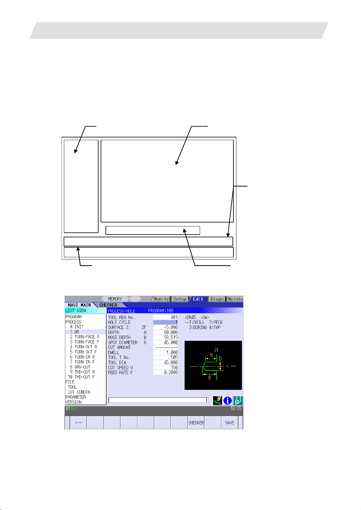
The screen of the NAVI LATHE is divided into the following five areas.
(1) LIST VIEW area (Refer to "2.1 LIST VIEW Area")
(2) OPERATION VIEW area (Refer to "2.2 OPERATION VIEW Area")
(3) Setting area (Refer to "2.3 Setting Area")
(4) Message area (Refer to "2.4 Message Area")
(5) Menu display area (Refer to "2.5 Menu Display Area")
(1) LIST VIEW area
(2) OPERATION VIEW area
(4) Message area
<Screen example>
(5) Menu display area
(3) Setting area
- 8 -
Page 23
2. FUNCTIONS OF DISPLAY AREA
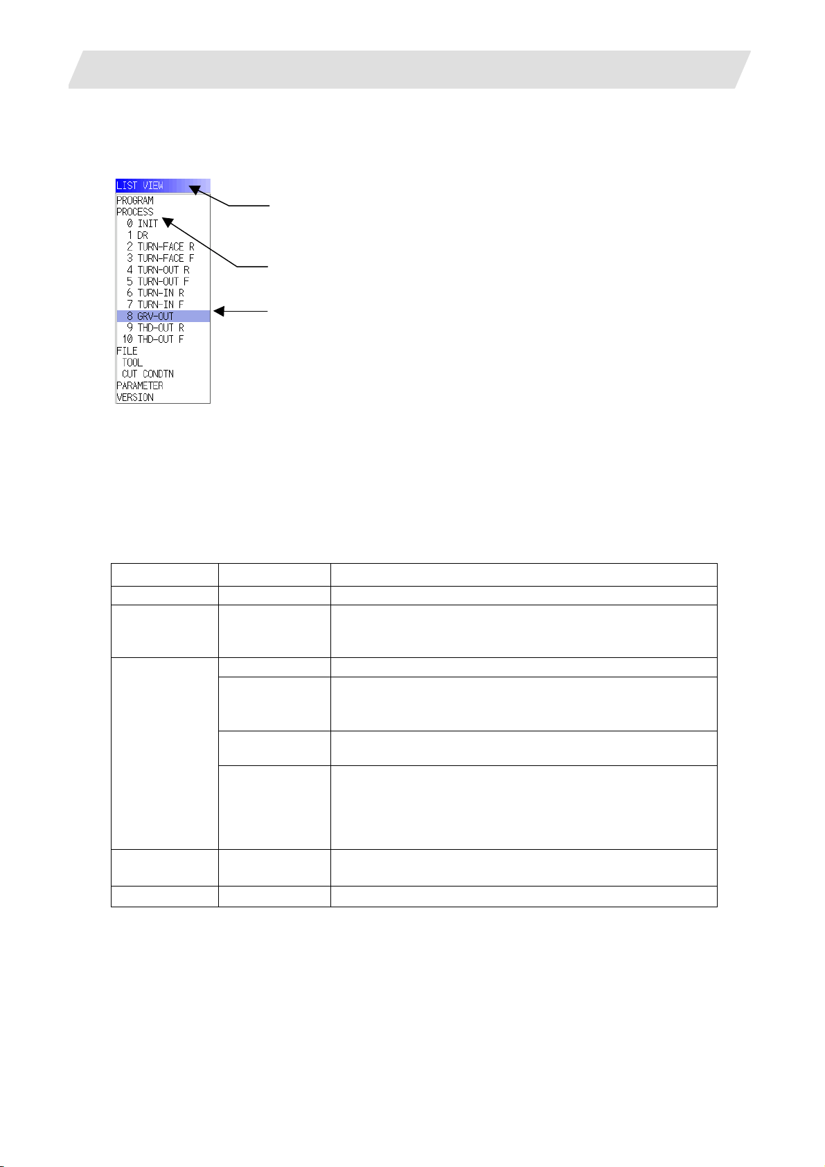
2.1 LIST VIEW Area
The object of the NAVI LATHE is selected in this area.
(1) Area bar
(2) Object
(3) Cursor
2.1 LIST VIEW Area
(1) Area bar
When the LIST VIEW area is active, the area bar is highlighted.
(2) Objects
The list of objects that can be selected are displayed. The object is composed of the main object and the
sub object, which is a specification of the main object. The details of each object are as follows.
Main object Sub object Details
PROGRAM - Newly creates, reads out, and deletes, etc. the NC program.
PROCESS 0 INIT
1 DR
:
FILE
PARAMETER - Displays the tool option and the miscellaneous parameter to
VERSION - Displays the version data of the NAVI LATHE.
(Note) If too many processes are registered and all the objects cannot be displayed, a scroll bar will be
displayed. In this case, change display of the list by pressing cursor key or page key down, or by
clicking on the scroll bar.
TOOL Displays and changes the tool file.
M TOOL Displays and changes the tool file for the milling machining.
CUT CONDTN Displays and changes the cutting conditions for each
M CUT
CONDTN
Displays the currently edited process list.
The settings of the selected process can be displayed and
changed.
(Note) This is valid when the milling interporation
process per tip material or workpiece material.
Displays and changes the cutting conditions for each
process per tip material or workpiece material for the milling
machining.
(Note) This file is valid when the milling interporation
be used in each process. Those can be changed.
specifications are provided.
specifications are provided.
- 9 -
Page 24

2. FUNCTIONS OF DISPLAY AREA
2.1 LIST VIEW Area
(3) Cursors
When the LIST VIEW area is active and the object is selected with the cursor, the display in the
OPERATION VIEW area and the menu display area will be changed.
<Cursor movement>
The cursor is moved using the cursor keys or a pointing device.
Key type Operation of cursor
[↑] Cursor key Moves the cursor one field up regardless of the main object or sub object.
Note that if the ↑ cursor is pressed when the cursor is at the top, the cursor
does not move.
[↓] Cursor key Moves the cursor one field down regardless of the main object or sub object.
Note that if the ↓ cursor is pressed when the cursor is at the bottom, the
cursor does not move.
[←] Cursor key When the cursor is at the sub object, moves the cursor to the previous main
object.
[→] Cursor key When the cursor is at the sub object, moves the cursor to the next main
object.
[Page Up] key Moves the displayed data toward the top.
[Page Down]
key
Pointing device Cursor jumps to the spot where clicked with a pointing device. If an object not
Moves the displayed data toward the bottom.
selectable is clicked, cursor does not jump.
- 10 -
Page 25
2. FUNCTIONS OF DISPLAY AREA
2.2 OPERATION VIEW Area
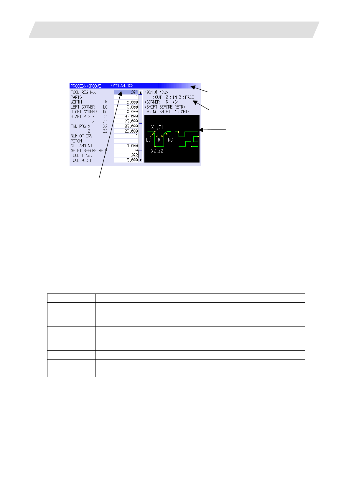
2.2 OPERATION VIEW Area
The various data are displayed in this area. Selecting the object in the LIST VIEW area changes the
contents displayed in the OPERATION VIEW area.
(1) Area bar
(2) Help
(3) Guide drawing
(4) Sub cursor
(1) Area bar
When the OPERATION VIEW area is active, the area bar is highlighted.
The name of the currently edited program is displayed.
(2) Help
Quick reference on the setting items is displayed.
(3) Guide drawing
When the process is edited, a guide drawing according to the currently edited machining mode is
displayed.
(4) Sub cursor
Key type Operation of cursor
[↑] Cursor key Moves the cursor one field up.
Note that if the ↑ cursor is pressed when the cursor is at the top, the cursor
does not move.
[↓] Cursor key Moves the cursor one field down.
Note that if the ↓ cursor is pressed when the cursor is at the bottom, the
cursor does not move.
[Page Up] key Moves the displayed data toward the top.
[Page Down]
key
Moves the displayed data toward the bottom.
- 11 -
Page 26

2. FUNCTIONS OF DISPLAY AREA
2.3 Setting Area
The value to be set to data is input.
2.4 Message Area
An error message or operation message, etc. during operation is displayed.
2.5 Menu Display Area
The screen operation is selected, and the screen is changed.
The different menus are displayed in each screen. (Refer to the chapter 4.)
2.3 Setting Area
- 12 -
Page 27
3. BASIC OPERATIONS
3.1 Changing Active View
3. BASIC OPERATIONS
3.1 Changing Active View
To operate NAVI LATHE, activate either LIST VIEW area or OPERATION VIEW area. When the VIEW is
active, the area bar is highlighted and data can be input. Use menu keys [←] and [→] or a pointing device
to switch either one of the VIEWs to be activated.
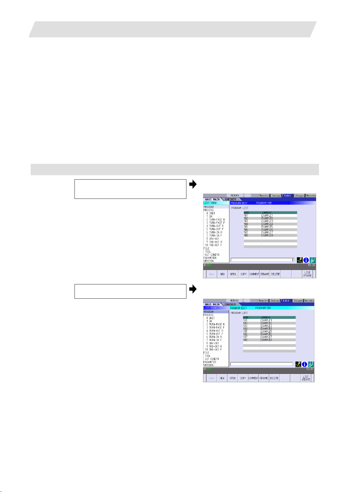
3.2 Changing Screen
When the object is selected in the LIST VIEW area, the screen (contents in the OPERATION VIEW area)
changes. (Refer to the section 2.1 LIST VIEW Area.)
Note that the screen cannot be changed while the OPERATION VIEW area is active.
In such a case, press the [←] menu key or click "LIST VIEW" with a pointing device to turn the LIST VIEW
area active.
Operation example
(1) Open the program edit screen.
The OPERATION VIEW area is active.
Press the [←] menu key. (2)
The LIST VIEW area will turn active.
- 13 -
Page 28
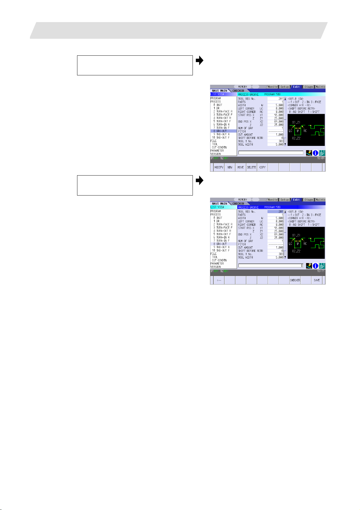
3. BASIC OPERATIONS
(3) Select the object with the cursor key.
3.2 Changing Screen
The OPERATION VIEW area will change
into the screen corresponding to the
selected object.
(4) Press the [MODIFY] menu key.
The OPERATION VIEW area will turn
active.
- 14 -
Page 29
3. BASIC OPERATIONS
3.3 Setting Data
3.3 Setting Data
After moving the sub cursor, input the data into the setting area and then press the [INPUT] key, and the
data will be set. (The sub cursor is displayed only when the OPERATION VIEW area is active.)
Sub cursor
Setting area
- 15 -
Page 30
3. BASIC OPERATIONS
Operation method
An example for setting the data on the hole drilling screen is shown below.
(1) Screen selection
Select the object to be changed from the
LIST VIEW and press [MODIFY] menu
key.
(2) Setting item selection
Move the sub cursor with cursor keys.
The OPERATION VIEW area will turn
active.
(Refer to the section 3.2 "Changing
screen".)
This is an example of the sub cursor
movement on the hole drilling screen.
3.3 Setting Data
(3) Data key input
Set data with the numeral keys or
alphabet keys, etc.
[1] [8] [.] [0] [0] [0]
The data is set in the data setting area.
18.000
(4) [INPUT] key input
Press the [INPUT] key.
Data for the selected setting item is set.
The sub cursor moves to the next position.
(Note 1) The contents in the data setting area are only displayed when [INPUT] key is not pressed and
will be invalidated if the screen is changed at this time. Data for the currently selected setting
item will be set when [INPUT] key is pressed.
(Note 2) If illegal data is set, an error occurs when [INPUT] is pressed. Set the correct data again.
- 16 -
Page 31

3. BASIC OPERATIONS
3.3 Setting Data
Operations in the data setting area
The key is input at the position where the cursor is displayed. If a cursor is not displayed, the key input is
invalid.
When a key is input, the data appears at the cursor position, and the cursor moves one character space
to the right.
[→] / [←] keys: Moves the cursor one character to the left or right.
(1) The cursor is at the position shown on
the right.
(2)
Press the [→] key.
[DETETE] key: Deletes the character in front of the cursor.
(1) Move the cursor to the position where
the data is to be deleted.
(2) Press the [DETETE] key.
1 2 3 7 7 7 | 4 5 6
The cursor moves one character space to
the right.
1 2 3 7 7 7 4 | 5 6
The cursor in the data setting area moves.
1 2 3 4 | 5 6
The character in front of the cursor is
deleted.
1 2 3 | 5 6
- 17 -
Page 32

3. BASIC OPERATIONS
3.4 Switching Windows
3.4 Switching Windows
When a shortcut button on the keyboard is pressed, its corresponding window is displayed.
Button Application
LIST
?
Displays the tool guidance window.
Displays the message guidance window.
Displays the checker window.
3.5 Switching Selection Tags
Menu tag
When a tag button on the keyboard is pressed, the main window and checker window can be switched
over.
Button Application
Selects the tag on the left.
Selects the tag on the right.
(Note 1) Depending on the keyboard specifications, tag button may not be available.
- 18 -
Page 33

3. BASIC OPERATIONS
3.6 Inputting Operations
3.6 Inputting Operations
In addition to the method of directly inputting numeric data for specific data settings, a method to input the
operation results using four rules operators and function symbols can be used.
Input method
Numeric values, function symbols, operators and parentheses ( ) are combined and set in the data
setting area.
The operation results appear when the [INPUT] key is pressed. Data for the currently selected setting
item will be set when [INPUT] key is pressed again.
The contents in the data setting area are erased.
Examples of operator settings,
and results
Operation
Setting
example
Operation
results
Function symbols, setting examples
and results
Function
Function
symbol
Setting
example
Operation
results
Addition =100+50 150.000
Subtraction =100−50 50.000 Square root SQRT =SQRT (3) 1.732
Multiplication =12.3∗4 49.200 Sine SIN =SIN (30) 0.5
Division =100/3 33.333 Cosine COS =COS (15) 0.966
Function
=1.2∗
(2.5+SQRT(4))
5.400
Circle ratio PAI =PAI*10 31.415
Inch INCH =INCH/10 2.54
Operation examples
(1) Set as shown below, and press the
[INPUT] key.
=12∗20 [INPUT]
(2) Press the [INPUT] key again.
Notes for using operators and functions
Division: Zero division causes an error.
Square root: If the value in the parentheses is negative, an error occurs.
Triangle function: The unit of angle θ is degree (°).
Arc tangent: −90 < operation results < 90.
Restrictions
• Always use "=" for the first character.
• Do not use the following characters as the second character or last character.
Invalid as second character: ∗, /, )
Invalid as last character: ∗, /, (, +, -
• Make sure that the left parentheses and right parentheses are balanced.
• The 360° limit does not apply on the angle. SIN (500) is interpreted as SIN (140).
Absolute
value
ABS
=ABS
(50−60)
10.000
Tangent TAN =TAN (45) 1
Arc tangent ATAN =ATAN (1.3) 52.431
The operation results appear in the data
setting area.
240 |
Data for the selected setting item is set.
The cursor moves to the next position.
- 19 -
Page 34

4. SCREEN SPECIFICATIONS
4. SCREEN SPECIFICATIONS
4.1 Starting NAVI LATHE
When NAVI LATHE is started, the program edit screen will be displayed.
Screen layout
4.1 Starting NAVI LATHE
At the initial start up of NAVI LATHE, the cursor is displayed at the position of [PROGRAM] in the LIST
VIEW area, and the program edit screen is displayed in the OPERATION VIEW area.
The LIST VIEW area is active.
The process program is not selected.
- 20 -
Page 35

4. SCREEN SPECIFICATIONS
4.2 Screen Related to the Program
4.2 Screen Related to the Program
4.2.1 Program Edit Screen
The NC program is newly created and read out, etc. on this screen. When [PROGRAM] is selected in the
LIST VIEW area, this screen is displayed.
Screen layout
The process list of the currently selected program is displayed in the LIST VIEW area.
- 21 -
Page 36

4. SCREEN SPECIFICATIONS
<Turning process displays>
4.2 Screen Related to the Program
Process name
Turning
Thread
Groove
Trapezoidal
grooving
Hole drilling
EIA EIA
OD OPEN TURN-OUT ?
OD CLOSE TURN-OUT ?
ID OPEN TURN-IN ?
ID CLOSE TURN-IN ?
FACE OPEN TURN-FACE ?
FACE CLOSE TURN-FACE ?
Outer diameter COPY OUT ? Copy cutting
Inner diameter COPY-IN ?
Outer diameter THD-OUT ?
Inner diameter THD-IN ?
Face THD-FACE ?
Outer diameter GRV-OUT
Inner diameter GRV-IN
Face GRV-FACE
Outer diameter TGRV-OUT ?
Inner diameter TGRV-IN ?
Face TGRV-FACE ?
Drill DR
Deep hole PECK
Step STEP
Tapping TAP
Display
character
A symbol that indicates the machining type
(rough/finishing) is put at ?.
• Rough machining: R
• Finishing machining: F
A symbol that indicates the machining type
(rough/finishing) is put at ?.
• Rough machining: R
• Finishing machining: F
A symbol that indicates the machining type
(rough/finishing) is put at ?.
• Rough machining: R
• Finishing machining: F
A symbol that indicates the machining type
(rough/finishing) is put at ?.
• Rough machining: R
• Finishing machining: F
Remarks
- 22 -
Page 37

4. SCREEN SPECIFICATIONS
<Milling process displays>
Process name Display
Milling
hole
drilling
Deep hole
Step M STEP-****
Tapping M TAP-****
Keyway
cutting
Outer surface K WAY-OUT ?
Side surface K WAY-SIDE ?
Contour
cutting
Outer surface CONT-OUT ?
Side surface CONT-SIDE ?
Screen display item
No. Display item Details Setting range
1
Drilling M DR-****
drilling
Front face K WAY-FACE ?
Front face CONT-FACE ?
PROGRAM LIST Displays the program number and comment of the
4.2 Screen Related to the Program
character
Symbols that indicate the machining area
(front face/outer surface/side surface) are put at
****.
M PECK-****
NC program that can be currently read out.
・Front face: FACE
・Outer surface: OUT
・Side surface: SIDE
A symbol that indicates machining type
(rough/finishing) is put at ?.
・Rough machining: R
・Finishing machining: F
Remarks
-
- 23 -
Page 38

4. SCREEN SPECIFICATIONS
r
Menus
No. Menu Details
← Turns the LIST VIEW area active.
1
NEW
2
OPEN
3
4.2 Screen Related to the Program
Newly creates the NC program. (Note 1)
< Display in the setting area when pressing the menu >
O( ) COMMENT( )
Reads out the existing NC program. (Note 1) (Note 2)
< Display in the setting area when pressing the menu >
O( )
When this menu is pressed, the cursor appears at the program list's
name section. When the setting area is empty, select a program with
the cursor and press the [INPUT] key to read the program.
4
COPY
Curso
Copies the existing NC program to another program. (Note 1)
< Display in the setting area when pressing the menu >
O( ) → O( )
COMMENT
5
Edits the comment in the NC program. (Note 1)
< Display in the setting area when pressing the menu >
O( ) COMMENT( )
6
RENAME
Renames the existing NC program. (Note 1)
< Display in the setting area when pressing the menu >
O( ) → O( )
DELETE Deletes the NC program.
7
< Display in the setting area when pressing the menu >
O( ) to O( )
LIST UPDATE Updates the list display.
8
(Note 1) 1 to 7999 or 10000 to 99999999 can be set for the O No, and up to 18 alphanumeric
characters can be set for the comment.
(Note 2) NC program mode includes user macro mode and MTB mode. (This is specified in the
preferences screen.) When user macro mode is active and an NC program created with MTB
mode is opened, the NC program is converted into user macro mode. When MTB mode is
active and an NC program created with user macro mode is opened, the NC program is
converted into MTB mode.
- 24 -
Page 39

4. SCREEN SPECIFICATIONS
Operation example (Opening the existing NC program)
(1) Select the [PROGRAM] in the LIST
VIEW area.
4.2 Screen Related to the Program
The program edit screen will be displayed.
The list of the NC program that can be read
out will be displayed.
Press the [OPEN] menu key, and input
(2)
the NC program No. to be read out.
Press the [INPUT] key.
(3)
The [OPEN] menu will be highlighted, and
the setting area will be displayed.
The highlight of the [OPEN] menu will turn
OFF, and the setting area will disappear.
The process of the NC program read out
will be displayed in the LIST VIEW area.
The NC program No. read out will be
displayed on the area bar of the
OPERATION VIEW area.
- 25 -
Page 40

4. SCREEN SPECIFICATIONS
4.3 Screen Related to the Process Edit Functions
4.3 Screens Related to the Process Edit Functions
4.3.1 Process List Screen
The tool information and cutting conditions for each process are displayed on this screen. When
[PROCESS] is selected in the LIST VIEW area, this screen is displayed.
When the NC program is not selected, this screen is not displayed.
Screen layout
Screen display items
No. Display item Details Setting range
PCS The process name is displayed.
1
T NAME The name of tool to be used is displayed. -
2
T The tool No. and compensation No. are displayed.
3
V The cutting speed is displayed.
4
F The feedrate is displayed. The feedrate can be
5
Menus
No. Menu Details
← Turns the LIST VIEW area active.
1
SAVE Saves changes in the process list.
2
(Note) This name is same as the name displayed in
the LIST VIEW area.
The tool No. can be changed.
T-command will not be output if the tool No. is set to
"0". Set the tool No. to "0" unless T-command
needs to be output, such as when the same tool is
used for the multiple consecutive processes.
The cutting speed can be changed.
changed. When TAP or THREAD process is
applied, the pitch (mm/rev) is displayed.
-
0 to 99999999
1 to 9999 m/min
1 to 9999 feet/min
0.0001 to 999.9999 mm/rev
0.00001 to
99.99999 inch/rev
- 26 -
Page 41

4. SCREEN SPECIFICATIONS
4.3 Screen Related to the Process Edit Functions
4.3.2 Operating Process
When the cursor is moved to the sub-object of PROCESS in the LIST VIEW area, a menu for editing the
process is displayed, and the process can be operated.
Screen layout
Menus
No. Menu Details
MODIFY The OPERATION VIEW area turns active, and the process
1
parameters can be changed.
NEW Adds a new process.
2
The process will be inserted into the cursor position.
MOVE Changes the process position.
3
DELETE Deletes the process at the cursor position.
4
When performing the deletion, the process under the deleted process
will be moved up.
COPY Copies the process at the cursor position.
5
The copied process will be inserted under the cursor position.
- 27 -
Page 42

4. SCREEN SPECIFICATIONS
Operation example (Selecting the process)
Validate the LIST VIEW area, select the
(1)
process with the cursor key.
4.3 Screen Related to the Process Edit Functions
The contents of the OPERATION VIEW
area will change to those of the selected
process.
Press the [MODIFY] menu key. (2)
The OPERATION VIEW area will turn
active.
- 28 -
Page 43

4. SCREEN SPECIFICATIONS
Operation example (Deleting the process)
Validate the LIST VIEW area, select the
(1)
process to be deleted with the cursor
key.
4.3 Screen Related to the Process Edit Functions
The contents of the OPERATION VIEW
area will change to those of the selected
process.
Press the [DELETE] menu key. (2)
Press the [Y] key. (3)
When not deleting the process, press
the [N] key
The [DELETE] menu will be highlighted,
and a massage confirming the deletion will
appear.
The highlight of the [DELETE] menu will
turn OFF, and the process at the cursor
position will be deleted.
The process under the deleted process will
be moved up one.
The contents in the OPERATION VIEW
area will change to those of the process at
the cursor position.
- 29 -
Page 44

4. SCREEN SPECIFICATIONS
Operation example (Copying the process)
Validate the LIST VIEW area, select the
(1)
process of the copy source with the
cursor key.
4.3 Screen Related to the Process Edit Functions
The contents of the OPERATION VIEW
area will change to those of the selected
process.
Press the [COPY] menu key. (2)
The copied process will be inserted under
the cursor position.
- 30 -
Page 45

4. SCREEN SPECIFICATIONS
Operation example (Moving the process)
Validate the LIST VIEW area, select the
(1)
process to be moved with the cursor
key.
4.3 Screen Related to the Process Edit Functions
The contents of the OPERATION VIEW
area will change to those of the selected
process.
Press the [MOVE] menu key. (2)
Select the position of the movement
(3)
destination with the cursor key.
The [MOVE] menu will be highlighted.
The mark "M" will be displayed beside the
process to be moved.
- 31 -
Page 46

4. SCREEN SPECIFICATIONS
Press the [INPUT] key.
(4)
If the [MOVE] menu key is pressed
again during the movement operation,
the movement operation will be
canceled.
4.3 Screen Related to the Process Edit Functions
The message to confirm a movement is
displayed.
Press the [Y] key. (5)
When not moving the process, press the
[N] key
(Note) For the [NEW] menu, refer to the next section.
The process of the movement source will
be moved to the cursor position.
The highlight of the [MOVE] menu will turn
OFF.
- 32 -
Page 47

4. SCREEN SPECIFICATIONS
4.3 Screen Related to the Process Edit Functions
4.3.3 Process Mode Selection Screen
When a new process is added, the process mode is selected on this screen.
Screen layout
• Turning process
• Milling Process
(Note) Milling process is available only when the milling interporation specifications are provided.
- 33 -
Page 48

4. SCREEN SPECIFICATIONS
Screen display item
• Turning process
No. Display item Details Setting range
Process mode Displays the process mode that can be selected for
1
• Milling Process
No. Display item Details Setting range
Process mode Displays the process mode that can be selected for
1
Menu
No. Menu Details
← Cancels adding a new process.
1
LATHE Displays the process mode for the turning machining.
2
MILLING Displays the process mode for milling.
3
4.3 Screen Related to the Process Edit Functions
1: TURN
the turning machining.
Select the process mode by moving the sub cursor
or inputting numerical values.
milling.
Select the process mode by moving the sub cursor
or inputting numerical values.
The LIST VIEW area will turn active after cancel.
(Note) This is valid when the milling interporation specifications are
provided.
(Note) This is valid when the milling interporation specifications are
provided.
2: COPY
3: GROOVE
4: T GROOVE
5: THREAD
6: HOLE
7: EIA
1: MILL HOLE
2: KEYWAY
3: CONTOUR
- 34 -
Page 49

4. SCREEN SPECIFICATIONS
Operation example (Adding a new process)
Validate the LIST VIEW area, and select
(1)
the position where the process is added
with the cursor key.
4.3 Screen Related to the Process Edit Functions
Press the [NEW] menu key. (2)
Select turning mode or milling mode by
pressing [LATHE] or [MILLING]
respectively.
Select the process mode with the cursor
(3)
or the numerical value input.
A blank process will be inserted into the
cursor position.
The process mode selection screen will be
displayed in the OPERATION VIEW area,
and the OPERATION VIEW area will turn
active.
- 35 -
Page 50

4. SCREEN SPECIFICATIONS
Press the [INPUT] key.
(4)
(Note) If the [←] menu key is pressed during adding the process, the screen will return to the state
before pressing the [NEW] menu key (state of the 1).
4.3 Screen Related to the Process Edit Functions
The contents in the OPERATION VIEW
area will change into those of the selected
process mode.
The selected process mode will be
displayed at the cursor position in the LIST
VIEW area.
- 36 -
Page 51

4. SCREEN SPECIFICATIONS
4.3 Screen Related to the Process Edit Functions
4.3.4 Initial Condition Setting Screen
The initial conditions for the program are set on this screen. When the [INIT] is selected in the LIST VIEW
area, this screen is displayed.
Screen layout
Screen display items
No. Display item Details Setting range
WORK REG No. Input the registration No. of the workpiece
1
1 to 8
material to be cut. Specify it with the No.
registered in the cutting condition file.
(The list of material names set on the cutting
condition file screen will be displayed. Input the
corresponding No. based on the list.)
WORK ZERO Input the program zero point.
2
Depending on the program zero point selection,
1 to 2
the program coordinate system is determined.
1: Tailstock side zero point
2: Chuck side zero point
+X
+Z
+X
+Z
Tail stock side zero point
Chuck side zero point
- 37 -
Page 52

4. SCREEN SPECIFICATIONS
No. Display item Details Setting range
OUTSIDE DIA Input the workpiece outer diameter. 0.001 to
3
INSIDE DIA Input the workpiece inner diameter. 0.000 to
4
+Z Input the workpiece face position looking from the
5
-Z Input the workpiece backside position looking from
6
WORK
7
COORDINATE
4.3 Screen Related to the Process Edit Functions
program zero point.
the program zero point.
Specify the workpiece coordinate system to be
used.
54 : G54
:
59 : G59
P1 : G54.1 P1
99999.999mm
0.0001 to
9999.9999inch
99999.999mm
0.0000 to
9999.9999inch
-99999.999 to
99999.999mm
-9999.9999 to
9999.9999inch
54 to 59
P1 to P48
:
P48 : G54.1 P48
COOLANT Select valid/invalid of the coolant.
8
0: Coolant invalid
1: Coolant valid
TOOL CHANGE
9
POS
Select the tool change position.
1: X axis: Reference position
Z axis: Tool turning clearance position
2: X axis, Z axis: Tool turning clearance position
3: X axis, Z axis: Tool fixed point return position
FIN TOOL RET Select the tool return type after the program end.
10
1: Reference position
2: Machining end position
3: Specified position
Reference position X
Tool turning
clearance X
Tool turning
clearance Z
Tool fixed
point return
position X
0 to 1
1 to 3
C1
C1
1 to 3
Tool fixed
point return
END POS X
11
END POS Z
12
position Z
Input the tool return position after the program end
by using machine coordinate system.
This is valid when end tool return type 3 (specified
position) is selected.
-99999.999 to
99999.999mm
-9999.9999 to
9999.9999inch
- 38 -
Page 53

4. SCREEN SPECIFICATIONS
No. Display item Details Setting range
END M CODE At the program end, select the M command to be
13
Menus
No. Menu Details
← Turns the LIST VIEW area active.
1
SAVE Saves the changes in the initial conditions.
2
output.
1 : M30
2 : M02
3 : M99
4.3 Screen Related to the Process Edit Functions
1 to 3
- 39 -
Page 54

4. SCREEN SPECIFICATIONS
4.3 Screen Related to the Process Edit Functions
4.3.5 Turning Screen
(1) Turning screen
The parameters for the turning process are input on this screen.
Screen layout
Screen display items
No. Display item Details Setting range
TOOL REG No. Input the registration No. of the tool to be used.
1
Use the No. registered in the tool file.
CYCLE Input the machining method.
2
<1: Rough machining>
Cuts into the cutting area gradually.
Leaves the finishing allowance for the
cutting shape.
<2: Finishing machining>
Machines the cutting shape in one cycle.
101 to 150
601 to 650
1,2
- 40 -
Page 55

4. SCREEN SPECIFICATIONS
A
A
No. Display item Details Setting range
PARTS Input the machining area.
3
4.3 Screen Related to the Process Edit Functions
<1: OD OPEN>
Machines the outer diameter area from the
front face of workpiece.
<2: OD CLOSE>
Machines the outer diameter area from the
halfway of workpiece.
<3: ID OPEN>
Machines the inner diameter area from the
front face of workpiece.
<4: ID CLOSE>
Machines inner area from the halfway of
workpiece.
<5: FACE OPEN>
Machines the front face of workpiece.
<6: FACE CLOSE>
Machines the front face from the halfway of
workpiece.
[OPEN type]
pproach point
1 to 6
Pe (Cutting shape end point)
[CLOSE type]
Pe (Cutting shape end point)
When the cutting shape is not incremented or
decremented monotonously, CLOSE type is
selected.
APPRCH POS X Input the approach point.
4
After machining, the tool returns to the approach
point.
APPRCH POS Z
5
Cutting
start point
pproach point
P1 (Cutting shape
start point)
Cutting start point
-99999.999 to
99999.999mm
-9999.9999 to
9999.9999inch
- 41 -
Page 56

4. SCREEN SPECIFICATIONS
A
A
4.3 Screen Related to the Process Edit Functions
No. Display item Details Setting range
FINISH ALLOW X
6
(FX)
FINISH ALLOW Z
7
(FZ)
CUT AMOUNT Input the cut amount for the rough machining. 0.001 to
8
RETRACT
9
AMOUNT
TOOL T No. Input the turret No. (or ATC No.) of the tool being
10
CUT SPEED V Input the cutting speed.
11
FEEDRATE F Input the feedrate.
12
(Addendum) The tool is retracted as shown below during rough machining.
[OPEN type] [CLOSE type]
The tool is retracted in 45˚ direction in
respect to the cutting shape.
Input the finishing allowance for the rough
machining.
Input both FX and FZ with radius value.
Input the retract amount for the rough machining. 0.0001 to
set, as well as the compensation No.
When tool registration No. is specified, tool No.
registered in the tool file is automatically set.
When tool registration No. is specified, cutting
speed is automatically set based on the contents
in the tool file and cutting condition file.
When tool registration No. is specified, feedrate
is automatically set based on the contents in the
tool file and cutting condition file.
The tool is retracted tracing the cutting shape.
pproach point
0.000 to
99999.999mm
0.0000 to
9999.9999inch
99.999mm
9.9999inch
0 to 99999999
1 to 9999 m/min
1 to 9999 feet/min
0.0001 to
999.9999 mm/rev
0.00001 to
99.99999 inch/rev
pproach point
Cutting start point
Cutting start point
(Note) Tool path is not provided based on the tool shape (tool nose angle, front edge angle, etc.)
Therefore, when the cutting shape is not incremented or decremented monotonously, take the
tool shape into consideration to input the cutting shape.
- 42 -
Page 57

4. SCREEN SPECIFICATIONS
4.3 Screen Related to the Process Edit Functions
Menus
No. Menu Details
← Turns the LIST VIEW area active.
1
PATTERN Machining pattern selection screen is displayed.
2
CHECKER Displays the checker screen. Select this to check the set data.
3
SAVE Saves the changes in the process.
4
If illegal parameters are found in saving, an error will be displayed.
When a parameter is incorrectly input, the cursor moves to that
parameter position. If illegal parameters are found in the pattern input
screen, the screen name and error will be displayed.
(2) Turning pattern screen
The cutting shapes for the turning process are input on this screen.
Screen layout
Screen display items
No. Display item Details Setting range
No. Shape No. 1 to 50
1
M Input the shape.
2
<1> Linear (G01) machining
<2> CW circular (G02) machining
<3> CCW circular (G03) machining
(Note) Not omittable.
- 43 -
1 to 3
Page 58

4. SCREEN SPECIFICATIONS
No. Display item Details Setting range
D Input right turn or left turn in respect to the vector
3
X
4
Z
4.3 Screen Related to the Process Edit Functions
at the end of the previous shape.
1: Left turn 2: Right turn
(Note 1) When nothing is input, it is regarded as
"contacting".
(Note 2) Omittable. However, when the end
point of the previous line, X and Z, is
uncertain, always input.
Turn to left Tangent Turn to right
Input the start point of a shape in the line No.1
and the end point of each shape in the line No.2
and after.
Specify with diameter value of the program
coordinate system for X and with radius value
for Z.
Z
1,2
-99999.999 to
99999.999mm
-9999.9999 to
9999.9999inch
X
(Note 1) Always input the coordinate in the final
line. Omittable except for the line No.1
and the last one.
(Note 2) Always input when the corner shape
dimension is input in the previous line.
R/A • When the shape is arc, input the radius of arc.
5
Positive value: Arc command smaller than 180°
Negative value: Arc command larger than 180°
• When the shape is linear, input the angle.
135°
(Note 1) Always input when the shape is arc.
(Note 2) When the shape is linear and the
coordinate X, Z or vector I, K is input,
this data is invalid.
Radius:
0.001 to
999999.999mm,
-999999.999 to
-0.001mm
Angle:
-359.999 to
360.000°
- 44 -
Page 59

4. SCREEN SPECIFICATIONS
No. Display item Details Setting range
I
6
K
4.3 Screen Related to the Process Edit Functions
• When the shape is arc, input the arc center
coordinate.
• When the shape is linear, input the gradient
(vector).
-99999.999 to
99999.999mm
-9999.9999 to
9999.9999inch
Z
80
40
I = 40.
K = 60.
4060
X
Z
I = 40.
K = 40.
80
40
(Note 1) When the shape is arc and only one of
either I or K is input, the other one is
regarded as "0".
(Note 2) When the shape is linear and the
coordinate X, Z or angle is input, this
data is invalid.
C Input the corner dimension.
7
Positive value: Corner R
Negative value: Corner C
R
C
(Note 1) When corner dimension is specified,
input the end point X, Y in the next line
in principle.
Menus
No. Menu Details
LINE INSERT Inserts the shape data in front of the cursor position.
1
(Note) This menu is not available when the cursor is at No.1
(machining start point).
LINE DELETE Deletes the shape data at the cursor position.
2
(Note) This menu is not available when the cursor is at No.1
(machining start point).
COPY Copies the previous line data at the cursor position.
3
+INPUT Inputs data at the cursor position with the data in the previous line
4
added.
(Note) This is valid only when inputting the coordinate X and Z.
CLEAR Clears the data at the cursor position.
5
RETURN Returns to the turning screen.
6
X
2060
-99999.999 to
99999.999mm
-9999.9999 to
9999.9999inch
- 45 -
Page 60

4. SCREEN SPECIFICATIONS
4.3 Screen Related to the Process Edit Functions
4.3.6 Copy Cutting Screen
(1) Copy cutting screen
The parameters for the copy cutting process are input on this screen.
Screen layout
Screen display items
No. Display item Details Setting range
TOOL REG No. Input the registration No. of the tool to be used.
1
CYCLE Input the machining method.
2
PARTS Input the machining area.
3
APPRCH POS X -99999.999 to
4
APPRCH POS Z
5
Use the No. registered in the tool file.
<1: Rough machining>
Cuts into the cutting area gradually.
Leaves the finishing allowance for the cutting
shape.
<2: Finishing machining>
Machines the cutting shape in one cycle.
<1: Outer diameter>
Machine the outer diameter section of the
workpiece.
<2: Inner diameter>
Machine the inner diameter section of the
workpiece.
Input the approach point.
After machining, the tool returns to the approach
point.
101 to 150
601 to 650
1,2
1 to 2
99999.999mm
-9999.9999 to
9999.9999inch
- 46 -
Page 61

4. SCREEN SPECIFICATIONS
No. Display item Details Setting range
MACH ALLOW X
6
(LX)
MACH ALLOW Z
7
(LZ)
FINISH ALLOW X
8
(FX)
FINISH ALLOW
9
FZ (FZ)
NUM OF CUTS Input the number of cuts for the rough
10
4.3 Screen Related to the Process Edit Functions
Input the allowance in X axis direction with the
radius value for the rough machining.
Input the allowance in Z axis direction for the
rough machining.
Input the finishing allowance for the rough
machining.
Input both FX and FZ with radius value.
machining.
0.001 to
99999.999mm
0.0001 to
9999.9999inch
0.000 to
99999.999mm
0.0000 to
9999.9999inch
1 to 99
Menus
TOOL T No. Input the turret No. (or ATC No.) of the tool being
11
set, as well as the compensation No.
When tool registration No. is specified, tool No.
registered in the tool file is automatically set.
CUT SPEED V Input the cutting speed.
12
When tool registration No. is specified, cutting
speed is automatically set based on the contents
in the tool file and cutting condition file.
FEED RATE F Input the feedrate.
13
When tool registration No. is specified, feedrate
is automatically set based on the contents in the
tool file and cutting condition file.
No. Menu Details
←
1
PATTERN Displays the machining pattern selection screen.
2
CHECKER Displays the checker screen. Select this to check the set data.
3
SAVE Saves the changes in the process.
4
Turns the LIST VIEW area active.
If illegal parameters are found in saving, an error will be displayed.
When a parameter is incorrectly input, the cursor moves to that
parameter position. If illegal parameters are input in the pattern input
screen, the screen name and error will be displayed.
1 to 999999
1 to 9999 m/min
1 to 9999 feet/min
0.0001 to
999.9999 mm/rev
0.00001 to
99.99999 inch/rev
- 47 -
Page 62

4. SCREEN SPECIFICATIONS
4.3 Screen Related to the Process Edit Functions
(2) Copy cutting pattern screen
The cutting shapes for the turning process are input on this screen.
Screen layout
Screen display items
Refer to the section "4.3.5 Turning Screen (2) Turning pattern screen".
Menus
No. Menu Details
LINE INSERT Inserts the shape data in front of the cursor position.
1
(Note) This menu is not available when the cursor is at No.1
(machining start point).
LINE DELETE Deletes the shape data at the cursor position.
2
(Note) This menu is not available when the cursor is at No.1
(machining start point).
COPY Copies the previous line data at the cursor position.
3
+INPUT Input data at the cursor position with the data in the previous line
4
added.
(Note) This is valid only when inputting the coordinate X and Z.
CLEAR Clears the data at the cursor position.
5
RETURN Returns to the copy cutting screen.
6
- 48 -
Page 63

4. SCREEN SPECIFICATIONS
4.3 Screen Related to the Process Edit Functions
4.3.7 Threading Screen
The parameters for the thread process are input on this screen.
Screen layout
Screen display items
No. Display item Details Setting range
TOOL REG No. Input the registration No. of the tool to be used.
1
Use the No. registered in the tool file.
CYCLE Input the machining method.
2
<1: Rough machining>
Cuts into the thread shape gradually.
Leaves the finishing allowance for the
thread shape.
<2: Finishing machining>
Machines the thread shape in one cycle.
PARTS Input the machining area.
3
<1: Outer diameter>
Thread the outer diameter area of the
workpiece.
<2: Inner diameter>
Thread the inner diameter area of the
workpiece.
<3: Face>
Thread the front area of the workpiece.
301 to 350
1,2
1 to 3
- 49 -
Page 64

4. SCREEN SPECIFICATIONS
No. Display item Details Setting range
CUT METHOD Select the threading cutting pattern for the rough
4
4.3 Screen Related to the Process Edit Functions
machining.
1: Constant area-normal
2: Constant area-zigzag
3: Constant depth-normal
4: Constant depth-zigzag
[Constant depth-normal] [Constant area-normal]
S in gl e c u tti n g am ou n t
S in gl e c u tti n g am ou n t
S in gl e c u tti n g am ou n t
[Constant area-z igzag] [Constant depth-zigz ag]
S3 S2 S1
1 to 4
S in gl e c u tti n g am ou n t
S in gl e c u tti n g am ou n t
S in gl e c u tti n g am ou n t
S3 S1 S2
ANG OF CUT (A) Input the cutting edge angle for the rough
5
machining.
When the cutting edge angle is set to 0, the
zigzag cutting pattern will be invalid.
Cutting edge angle = 0 Cutting edge angle 0
Cutting edge angle
Cutting edge angle
Cutting edge angle 0
PITCH (P) Input the screw pitch. 0.0001 to
6
HEIGHT (H) Input the thread height.
7
When selecting a thread type from the menu,
thread height can be input automatically based
on the pitch.
M
MET
ER
START POS X
8
(X1)
START POS Z
9
(Z1)
END POS X (X2) Input the X coordinate of the threading end point
10
Input the X coordinate of the threading start point
in the diameter value.
Input the Z coordinate of the threading start
point.
UN
UNI
FY
W
WIT
PF PT
PS
PIPI
NG
NPT
PIPI
NG
TM
TRA
P.30
°
TW
TRA
P.29
°
in the diameter value.
0.000 to
60.000°
999.9999mm
0.00001 to
99.99999inch
0.001 to
999.999mm
0.0001 to
9999.9999mm
-99999.999 to
99999.999mm
-9999.9999 to
9999.9999inch
-99999.999 to
99999.999mm
- 50 -
Page 65

4. SCREEN SPECIFICATIONS
No. Display item Details Setting range
END POS Z (Z2) Input the Z coordinate of the threading end point. -9999.9999 to
11
FIN ALLOW Input the threading finishing allowance for the
12
CUT AMOUNT Input the cutting amount corresponding the
13
CHM. ANGLE Input the chamfering angle.
14
CHM. AMOUNT Input the chamfering amount.
15
TOOL T No. Input the turret No. (or ATC No.) of the tool being
16
CUT SPEED V Input the cutting speed.
17
4.3 Screen Related to the Process Edit Functions
rough machining.
Chamfered section is machined as continuous
thread.
respective methods below for the rough
machining.
<Constant cutting amount method>
Maximum cutting amount per cut is input.
Cutting amount is calculated according to the
following formula, and the average is taken.
Number of cutting cycles =
((Thread height - Threading finishing
allowance)/Cutting amount) ↑
↑: Rounded up
Actual cutting amount =
(Thread height – Threading finishing
allowance)/Number of cutting cycles
<Constant area method>
Initial cutting amount is input.
"n" th cutting amount (dn) is calculated
according to the following formula.
dn = d1( √n - √(n-1) )
d1: Initial cutting amount
0: No chamfering
1: 45
°
2: 60
°
Chamfering is not carried out when:
Thread angle + chamfering angle > 90°
Chamfered section is machined as continuous
thread.
set, as well as the compensation No.
When tool registration No. is specified, tool No.
registered in the tool file is automatically set.
When tool registration No. is specified, cutting
speed is automatically set based on the contents
in the tool file and cutting condition file.
9999.9999inch
0.000 to
99999.999mm
0.0000 to
9999.9999inch
0.001 to
99999.999mm
0.0001 to
9999.9999inch
0 to 2
0.1 to 9.9
(Number of
threads)
1 to 999999
1 to 9999 m/min
1 to 9999 feet/min
- 51 -
Page 66

4. SCREEN SPECIFICATIONS
Menus
No. Menu Details
← Turns the LIST VIEW area active.
1
CHECKER Displays the checker screen. Select this to check the set data.
2
SAVE Saves the changes in the process.
3
4.3 Screen Related to the Process Edit Functions
If illegal parameters are found in saving, an error will be displayed.
When a parameter is incorrectly input, the cursor moves to that
parameter position.
- 52 -
Page 67

4. SCREEN SPECIFICATIONS
4.3 Screen Related to the Process Edit Functions
4.3.8 Grooving Screen
The parameters for the groove process are input on this screen.
Screen layout
Screen display items
No. Display item Details Setting range
TOOL REG No. Input the registration No. of the tool to be used.
1
201 to 250
Use the No. registered in the tool file.
PARTS Input the machining area.
2
1 to 3
<1: Outer diameter>
Groove the outer diameter area of the
workpiece.
<2: Inner diameter>
Groove the inner diameter area of the
workpiece.
<3: Face>
Groove the front area of the workpiece.
WIDTH (W) Input the groove width. 0.001 to
3
99999.999mm
0.0001 to
9999.9999inch
LEFT CORNER
4
(LC)
Input the dimension of the left groove corner.
Positive value: Corner R
Negative value: Corner C
-99999.999 to
99999.999mm
-9999.9999 to
9999.9999inch
R
C
Corner R/C cannot be specified for taper
grooving.
- 53 -
Page 68

4. SCREEN SPECIFICATIONS
No. Display item Details Setting range
RIGHT CORNER
5
(RC)
START POS X
6
(X1)
START POS Z
7
(Z1)
END POS X (X2) Input the X coordinate of the grooving end point
8
END POS Z (Z2) Input the Z coordinate of the grooving end point.
9
4.3 Screen Related to the Process Edit Functions
Input the dimension of the right groove corner.
Positive value: Corner R
Negative value: Corner C
Corner R/C cannot be specified for taper
-99999.999 to
99999.999mm
-9999.9999 to
9999.9999inch
grooving.
Input the X coordinate of the grooving start point
in the diameter value.
-99999.999 to
99999.999mm
Input the Z coordinate of the grooving start point. -9999.9999 to
9999.9999inch
in the diameter value.
Groove
width
Star t point X1,Z1
Outer
dia.
groove
End point X2,Z2
End point X2,Z2
End point X2,Z 2
Inner
dia.
groove
Start point X1,Z1
Front
face
groove
Start point X1,Z1
NUM OF GRV Input the number of grooves to be machined. 1 to 99
10
PITCH
11
Groove pitch
Gr oove pitch direct ion
+ -
+
Outer
dia.
groove
Front face
groove
Inner
dia.
groove
-
-
+
CUT AMOUNT Input the cut amount. 0.001 to
12
-99999.999 to
99999.999mm
-9999.9999 to
9999.9999inch
99999.999mm
0.0001 to
9999.9999inch
- 54 -
Page 69

4. SCREEN SPECIFICATIONS
No. Display item Details Setting range
SHIFT BEFORE
13
RETR
TOOL T No. Input the turret No. (or ATC No.) of the tool being
14
TOOL WIDTH Input the tool width of the respective tool.
15
CUT SPEED V Input the cutting speed.
16
FEED RATE F Input the feedrate.
17
Menus
No. Menu Details
← Turns the LIST VIEW area active.
1
CHECKER Displays the checker screen. Select this to check the set data.
2
SAVE Saves the changes in the process.
3
4.3 Screen Related to the Process Edit Functions
Specify whether to shift the tool with cutting feed
toward the machined area after reaching the
groove bottom second or more time.
0: Not shifted
1: Shifted
set, as well as the compensation No.
When tool registration No. is specified, tool No.
registered in the tool file is automatically set.
When tool registration No. is specified, tool width
registered in the tool file is automatically set.
When tool registration No. is specified, cutting
speed is automatically set based on the contents
in the tool file and cutting condition file.
When tool registration No. is specified, feedrate
is automatically set based on the contents in the
tool file and cutting condition file.
If illegal parameters are found in saving, an error will be displayed.
When a parameter is incorrectly input, the cursor moves to that
parameter position.
0 to 1
1 to 999999
0.001 to
999.999mm
0.0001 to
99.9999 inch
1 to 9999 m/min
1 to 9999 feet/min
0.0001 to
999.9999 mm/rev
0.00001 to
99.99999 inch/rev
- 55 -
Page 70

4. SCREEN SPECIFICATIONS
4.3 Screen Related to the Process Edit Functions
4.3.9 Trapezoidal Grooving Screen
The parameters for the trapezoidal groove process are input on this screen.
Screen layout
Screen display items
No. Display item Details Setting range
TOOL REG No. Input the registration No. of the tool to be used.
1
Use the No. registered in the tool file.
CYCLE Input the machining method.
2
<1: Rough machining>
Cuts into the trapezoidal groove shape
gradually.
Leaves the finishing allowance for the
trapezoidal groove shape.
<2: Finishing machining>
Machines the trapezoidal groove shape in
one cycle.
PARTS Input the machining area.
3
<1: Outer diameter>
Groove the outer diameter area of the
workpiece.
<2: Inner diameter>
Groove the inner diameter area of the
workpiece.
<3: Face>
Groove the front area of the workpiece.
BASE POS X Input the X coordinate, basic point of the
4
trapezoidal groove (the bottom center of the
trapezoidal groove), in the diameter value.
201 to 250
1,2
1 to 3
-99999.999 to
99999.999mm
- 56 -
Page 71

4. SCREEN SPECIFICATIONS
No. Display item Details Setting range
BASE POS Z Input the Z coordinate, basic point of the
5
WIDTH (W) Input the groove width.
6
DEPTH 1 (H1) Input the left-side depth of the groove. 0.0001 to
7
DEPTH 2 (H2) Input the right-side depth of the groove.
8
GRV ANG 1 (A1) Input the angle between the bottom and left-side
9
GRV ANG 2 (A2) Input the angle between the bottom and
10
GRV ANG 3 (A3) Input the angle between the left-side of the
11
GRV ANG 4 (A4) Input the angle between the right-side of the
12
4.3 Screen Related to the Process Edit Functions
trapezoidal groove (the bottom center of the
trapezoidal groove), in the diameter value.
surface of the groove.
right-side surface of the groove.
groove and the workpiece surface.
groove and the workpiece surface.
A3 A4
-9999.9999 to
9999.9999inch
0.001 to
99999.999mm
9999.9999inch
0.000 to 89.999°
0.000 to 89.999°
-89.999 to 89.999°
-89.999 to 89.999°
E1 E2
A1 A2
H1 H
2
ENTR L-COR
13
(E1)
X,Z
B1 B2
W
Input the left corner amount of trapezoidal
groove entrance.
Positive value: Corner R
Negative value: Corner C
ENTR R-COR
14
(E2)
Input the right corner amount of trapezoidal
groove entrance.
Positive value: Corner R
Negative value: Corner C
BOT L-COR (B1) Input the left corner amount of trapezoidal
15
groove bottom.
Positive value: Corner R
Negative value: Corner C
BOT R-COR (B2) Input the right corner amount of trapezoidal
16
groove bottom.
Positive value: Corner R
Negative value: Corner C
FIN ALLOW Input the finishing allowance of the groove for
17
the rough machining.
CUT AMOUNT Input the cut amount. 0.001 to
18
-99999.999 to
99999.999mm
-9999.9999 to
9999.9999inch
0.000 to
99999.999mm
0.0000 to
9999.9999inch
99999.999mm
0.0001 to
9999.9999inch
- 57 -
Page 72

4. SCREEN SPECIFICATIONS
No. Display item Details Setting range
TOOL T No. Input the turret No. (or ATC No.) of the tool being
19
TOOL WIDTH Input the tool width of the respective tool.
20
CUT SPEED V Input the cutting speed.
21
FEED RATE F Input the feedrate.
22
Menus
No. Menu Details
← Turns the LIST VIEW area active.
1
CHECKER Displays the checker screen. Select this to check the set data.
2
SAVE Saves the changes in the process.
3
4.3 Screen Related to the Process Edit Functions
1 to 999999
set, as well as the compensation No.
When tool registration No. is specified, tool No.
registered in the tool file is automatically set.
0.001 to
When tool registration No. is specified, tool width
registered in the tool file is automatically set.
When tool registration No. is specified, cutting
speed is automatically set based on the contents
in the tool file and cutting condition file.
When tool registration No. is specified, feedrate
is automatically set based on the contents in the
tool file and cutting condition file.
If illegal parameters are found in saving, an error will be displayed.
When a parameter is incorrectly input, the cursor moves to that
parameter position.
999.999mm
0.0001 to
99.9999inch
1 to 9999 m/min
1 to 9999 feet/min
0.0001 to
999.9999 mm/rev
0.00001 to
99.99999 inch/rev
- 58 -
Page 73

4. SCREEN SPECIFICATIONS
4.3 Screen Related to the Process Edit Functions
4.3.10 Hole Drilling Screen
Miscellaneous parameters related to the hole drilling process patterns are input on this screen. This is
displayed when PATTERN menu is pressed on the hole drilling screen.
Screen layout
Screen display items
No. Display item Details Setting range
TOOL REG No. Input the registration No. of the tool to be used.
1
Use the No. registered in the tool file.
HOLE CYCLE Input the type of hole machining cycle.
2
<1: Drill> (G83)
The machining is performed as far as the
hole bottom at a stretch, and the tool is
lifted up after the hole bottom dwell has
been executed.
<2: Deep hole> (G83)
The machining is performed halfway of the
hole, and the tool is returned to the higher
than the hole top position each time. The
machining is performed as far as the hole
bottom by repeating such operations.
<3: Boring cycle> (G85)
The machining is performed as far as the
hole bottom at a stretch, and the tool is
lifted up with the cutting feedrate after the
hole bottom dwell has been executed.
<4: Tapping> (G84,G84.1)
The tap machining is performed as far as
the hole bottom, and the tool is lifted up
with the reversed rotation after the hole
bottom dwell has been executed.
401 to 450
501 to 550
1 to 4
- 59 -
Page 74

4. SCREEN SPECIFICATIONS
No. Display item Details Setting range
SURFACE Z (ZF) Input the top surface position of the hole. -99999.999 to
3
DEPTH (H) Input the hole depth from the workpiece top
4
NOSE DEPTH (B) Input the nose depth from the workpiece top
5
SPOT
6
DIAMETER (D)
CUT AMOUNT When selecting the hole cycle type C=2(deep
7
DWELL Input the dwell time at the bottom of the hole. 0.0 to 99.999sec
8
TOOL T No. Input the turret No. (or ATC No.) of the tool being
9
TOOL DIA Input the tool radius of the respective tool.
10
CUT SPEED V Input the cutting speed.
11
FEED RATE F Input the feedrate.
12
Menus
No. Menu Details
← Turns the LIST VIEW area active.
1
CHECKER Displays the checker screen. Select this to check the set data.
2
SAVE Saves the changes in the process.
3
4.3 Screen Related to the Process Edit Functions
99999.999mm
-99999.999 to
surface with the addition input method.
When the hole depth is changed, tool nose
depth will be automatically updated.
If the calculated nose depth is 0 or below, the
data range will be over.
surface with the addition input method.
When the nose depth is changed, hole depth will
be automatically updated.
Input the spot diameter. When inputting the spot
diameter, hole depth and nose depth are
automatically changed.
hole), input the cut amount per cut.
set, as well as the compensation No.
When tool registration No. is specified, tool No.
registered in the tool file is automatically set.
When tool registration No. is specified, tool
radius registered in the tool file is automatically
set.
When tool registration No. is specified, cutting
speed is automatically set based on the contents
in the tool file and cutting condition file.
When the type of hole machining cycle is TAP,
the pitch (mm/rev) is displayed.
When tool registration No. is specified, feedrate
is automatically set based on the contents in the
tool file and cutting condition file.
If illegal parameters are found in saving, an error will be displayed.
When a parameter is incorrectly input, the cursor moves to that
parameter position.
99999.999mm
-9999.9999 to
9999.9999inch
0.001 to
99999.999mm
0.001 to
Tool diameter
0.001 to
99999.999mm
1 to 999999
0.001 to
999.999mm
0.0001 to
99.9999inch
1 to 9999 m/min
1 to 9999 feet/min
0.0001 to
999.9999 mm/rev
0.00001 to
99.99999 inch/rev
- 60 -
Page 75

4. SCREEN SPECIFICATIONS
4.3.11 EIA Screen
The EIA process is input on this screen.
Screen layout
4.3 Screen Related to the Process Edit Functions
Screen display item
No. Display item Details Setting range
EIA BLOCK The current contents of the EIA block are displayed.
1
Menus
No. Menu Details
← Turns the LIST VIEW area active.
1
INSERT Inserts a blank block before the block where the cursor exists.
2
DELETE Deletes the data of the block where the cursor exists.
3
SAVE Saves the changes in the process.
4
Register the EIA by inputting the EIA from the
setting area. Note that there is the following
restriction.
<Restriction>
• Characters that can be input into the EIA block are
up to 50 characters.
EIA code
Max. 10 blocks
- 61 -
Page 76

4. SCREEN SPECIFICATIONS
4.3 Screen Related to the Process Edit Functions
4.3.12 Milling Hole Drilling Screen
(1) Milling hole drilling screen
The parameters for the milling hole drilling are input on this screen.
Screen layout
Screen display items
No. Display item Details Setting range
TOOL REG
1
No.
PARTS Input the machining area.
2
Input the registration No. of the tool to be used.
Use the No. registered in the tool file.
<1: FACE>
Machines the front face of workpiece.
<2: OUT>
Machines the outer surface of workpiece.
<3: SIDE>
Machines the side surface of workpiece.
Y-axis specifications are required for the side cutting.
Side surface
Front face
701 to 799
1 to 3
Outer surface
- 62 -
Page 77

4. SCREEN SPECIFICATIONS
X
X
X
No. Display item Details Setting range
HOLE CYCLE Input the type of hole machining cycle.
3
BASE PLANE
4
BZ
BASE PLANE
BR
BASE PLANE
BA
DEPTH H Input the hole depth from the workpiece top surface
5
NOSE
6
DEPTH B
4.3 Screen Related to the Process Edit Functions
<1: DRILL>(G83,G87)
The machining is performed as far as the hole
bottom at a stretch, and the tool is lifted up
after the hole bottom dwell has been executed.
<2: PECK>(G83, G87)
The machining is performed as far as the middle
of the hole, and the tool is returned to the higher
position than the hole top each time.
The machining is performed as far as the hole
bottom with such operation repeatedly executed.
<3: BORE>(G85, G89)
The machining is performed as far as the hole
bottom at a stretch, and the tool is lifted up
with cutting feed after the hole bottom dwell has
been executed.
<4: TAP>(G84, G84.1, G88, G88.1)
The tap machining is performed as far as the hole
bottom, and the tool is lifted up with reversed
rotation after the hole bottom dwell has been
executed.
Set the hole top position in respect to the machining
area.
[Front face]
[Side surface]
BZ
BA
BR
[Outer surface]
Z
Z
BR
Z
BASE PLANE BZ/BR are switched according to the
machining area.
BASE PLANE BA is set only for the side cutting.
with an addition input method.
When the hole depth is changed, nose depth is
automatically updated.
If the calculated nose depth is 0 or below, the data is
out of the range.
Input the tool nose depth from the workpiece top
surface with an addition input method.
When the nose depth is changed, hole depth is
automatically updated.
1 to 4
Base plane BZ
-99999.999 to
99999.999mm
-9999.9999 to
9999.9999inch
Base plane BR
0.001 to
99999.999mm
0.0001 to
9999.9999inch
Base plane BA
-359.999 to
360.000°
-99999.999 to
99999.999mm
-9999.9999 to
9999.9999inch
0.001 to
99999.999mm
0.0001 to
9999.9999inch
- 63 -
Page 78

4. SCREEN SPECIFICATIONS
No. Display item Details Setting range
SPOT
7
DIAMETER D
CUT
8
AMOUNT
DWELL Input the dwell time at the bottom of the hole. 0.0 to
9
RETURN
10
POINT
4.3 Screen Related to the Process Edit Functions
Input the spot diameter.
When inputting the spot diameter, hole depth and nose
depth are automatically changed.
Input the cutting amount per cut when the hole cycle
type C=2 (PECK) is selected.
When machining multiple holes, select the height of the
tool movement to the next hole position.
1:Initial point level return
2:R point level return
Initial point level return -OUT-
R point level return -OUT-
0.001 to
Tool diameter
(mm)
0.0001 to
Tool diameter
(inch)
0.001 to
99999.999mm
0.0001 to
9999.9999inch
99.999sec
1,2
Safe profile clearance
Hole clearance
11
C-AXIS
CLAMP
Initial point level return -FACE-
Safe profile clearance
Select whether to clamp C axis or not in the machining.
Select “Clamp C axis” for heavy load machining.
R point level return -FACE-
Hole clearance
0,1
0:Invalid
1:Valid
PATTERN The machining pattern is displayed.
12
RANDOM LINE
ARC CIRCLE
SQUARE GRID
Change the machining pattern on the machining pattern
screen.
TOOL T No. Input the turret No. (or ATC No.) of the tool being set,
13
0 to 99999999
as well as the compensation No.
When tool registration No. is specified, the tool No.
registered in the tool file is automatically set.
DIA Input the tool diameter.
14
When tool registration No. is specified, the tool
diameter registered in the tool file is automatically set.
0.001 to
999.999mm
0.0001 to
99.9999inch
- 64 -
Page 79

4. SCREEN SPECIFICATIONS
No. Display item Details Setting range
CUT SPEED V Input the cutting speed.
15
FEED RATE F Input the feedrate.
16
Menus
No. Menu Details
←
1
PATTERN The machining pattern selection screen is displayed.
2
CHECKER Displays the checker screen. Select this to check the set data.
3
SAVE Saves the changes in the process.
4
4.3 Screen Related to the Process Edit Functions
When tool registration No. is specified, cutting speed is
automatically set based on the contents in the tool file
and cutting condition file.
When the type of the hole machining cycle is TAP, the
pitch (mm/rev) is displayed.
When tool registration No. is specified, feedrate is
automatically set based on the contents in the tool file
and cutting condition file.
Turns the LIST VIEW area active.
If illegal parameters are found in saving, an error will be displayed.
When a parameter is incorrectly input, the cursor moves to that
parameter position.
1 to 9999
m/min
1 to 9999
feet/min
0.0001 to
999.9999
mm/rev
0.00001 to
99.99999
inch/rev
- 65 -
Page 80

4. SCREEN SPECIFICATIONS
4.3 Screen Related to the Process Edit Functions
(2) Hole Drilling Pattern Screen
Various parameters for hole drilling patterns are input on this screen. When the [PATTERN] menu is
pressed on the hole drilling screen, this screen is displayed.
Screen layout
Machining area and hole machining pattern
The hole machining patterns selectable for each machining area are as follows.
Pattern
Machining
area
Front face
Outer surface
Side surface
Random Line Arc Circle Square Grid
{
{
{
{
{
{
{
{
×
{
×
{
{: Selectable, ×: Not selectable
{
{
×
{
{
×
- 66 -
Page 81

4. SCREEN SPECIFICATIONS
4.3 Screen Related to the Process Edit Functions
Screen display items
No. Display item Details Setting range
PATTERN Input the type of hole machining pattern.
1
<1: RANDOM>
The machining points are randomly arranged.
<2: LINE>
The machining points are equally spaced on a
line.
<3: ARC>
The machining points are equally spaced on an
arc.
<4: CIRCLE>
The machining points are equally spaced on a
circle.
<5: SQUARE>
The machining points are squarely arranged.
<6: GRID>
The machining points are arranged in grid.
(Note) If the pattern entered is not selectable for the
machining area, the message “E002 Data range over”
will appear.
(Note) Display items No.2 and later differ according to each pattern.
1 to 6
- 67 -
Page 82

4. SCREEN SPECIFICATIONS
X
Y
・Parameters for RANDOM
Front face Outer surface Side surface
4.3 Screen Related to the Process Edit Functions
No. Display
Details Setting range
item
HOLE No. Input the hole No. 1 to 35
2
3
FACE:
POS X
POS Y
OUT:
POS C
POS Z
SIDE:
POS Y
POS Z
Input the hole position.
[Front face]
[Side face]
Z
Y
y
y
z
[Outer circumference]
Z
x
c
180
z
270
360
C
X,Y,Z:
-99999.999 to
99999.999mm
-9999.9999 to
9999.9999inch
90
C:
-359.999 to
360.000
- 68 -
Page 83

4. SCREEN SPECIFICATIONS
・Parameters for LINE
Front face Outer surface Side surface
No. Display item Details Setting range
FACE:
2
BASE POS X
BASE POS Y
OUT:
BASE POS C
BASE POS Z
SIDE:
BASE POS Y
BASE POS Z
4.3 Screen Related to the Process Edit Functions
Set the first hole position for the machining area. X,Y,Z:
-99999.999 to
99999.999mm
-9999.9999 to
9999.9999inch
C:
-359.999° to
360.000°
ANGLE (A)
3
PITCH (A)
Front face:
Input the angle formed with the machining
direction and the positive direction of the
X axis.
Outer surface:
Input the pitch angle in respect to the
machining direction.
Side surface:
Input the angle formed with the machining
direction and the positive direction of the
Y axis.
PITCH (K) Input the space from the machining point to the
4
next machining point.
5
NUM OF
Input the number of holes. 2 to 999
HOLES
OMIT 1 to 4 Specify the hole No. to be omitted (deleted).
6
Maximum hole No. that can be specified is 127.
-359.999° to
360.000°
-99999.999 to
99999.999mm
-9999.9999 to
9999.9999inch
1 to number of
holes
- 69 -
Page 84

4. SCREEN SPECIFICATIONS
・Parameters for ARC
Front face Side surface
4.3 Screen Related to the Process Edit Functions
No. Display item Details Setting range
2
FACE:
SIDE:
BASE POS X
BASE POS Y
BASE POS Y
Input the arc center position. X,Y,Z:
-99999.999 to
99999.999mm
-9999.9999 to
9999.9999inch
BASE POS Z
RADIUS R Input the arc radius. 0.001 to
3
99999.999mm
0.0001 to
9999.9999inch
START
4
ANGLE A
Front face:
Input the angle formed with the first
-359.999° to
360.000°
machining point and the positive direction of
the X axis.
Side surface:
Input the angle formed with the first
machining point and the positive direction of
the Y axis.
PITCH K Input the angle from the previous machining point
5
to the next machining point.
6
NUM OF
Input the number of holes. 2 to 999
-359.999° to
360.000°
HOLES
OMIT 1 to 4 Specify the hole No. to be omitted (deleted).
7
Maximum hole No. that can be specified is 127.
1 to number of
holes
- 70 -
Page 85

4. SCREEN SPECIFICATIONS
・Parameters for CIRCLE
Front face Side surface
4.3 Screen Related to the Process Edit Functions
No. Display item Details Setting range
2
FACE:
SIDE:
BASE POS X
BASE POS Y
BASE POS Y
Input the circular center position. X,Y,Z:
-99999.999 to
99999.999mm
-9999.9999 to
9999.9999inch
BASE POS Z
DIAMETER
3
D
Input the circular diameter. 0.001 to
99999.999mm
0.0001 to
9999.9999inch
START
4
ANGLE A
Front face:
Input the angle formed with the first
-359.999° to
360.000°
machining point and the positive direction of
the X axis.
Side surface:
Input the angle formed with the first
machining point and the positive direction of
the Y axis.
5
NUM OF
Input the number of holes. 1 to 999
HOLES
OMIT 1 to 4 Specify the hole No. to be omitted (deleted).
6
Maximum hole No. that can be specified is 127.
1 to number of
holes
- 71 -
Page 86

4. SCREEN SPECIFICATIONS
・Parameters for SQUARE
Front face Side surface
4.3 Screen Related to the Process Edit Functions
No. Display item Details Setting range
2
FACE:
SIDE:
BASE POS X
BASE POS Y
BASE POS Y
Input the position of the machining start point. X,Y,Z:
-99999.999mm to
99999.999mm
-9999.9999 to
9999.9999inch
BASE POS Z
X WIDTH I Input the width of the machining point in the X
3
axis direction.
-99999.999mm to
99999.999mm
-9999.9999 to
9999.9999inch
X NUM OF
4
HOLES
Y WIDTH J Input the width of the machining point in the Y
5
Input the number of machining points in the X
axis direction.
axis direction.
2 to 999
-99999.999mm to
99999.999mm
-9999.9999 to
9999.9999inch
Y NUM OF
6
HOLES
ANGLE A Front face:
7
Input the number of machining points in the Y
axis direction.
Input the angle formed with the machining
2 to999
-359.999° to
360.000°
start direction and the X axis.
Side surface:
Input the angle formed with the machining
start direction and the Y axis.
ANGLE B Input the interior angle.
8
Default value is 90°.
OMIT 1 to 4 Specify the hole No. to be omitted (deleted).
9
Maximum hole No. that can be specified is 127.
0.001° to
179.999°
1 to number of
holes
- 72 -
Page 87

4. SCREEN SPECIFICATIONS
・Parameters for GRID
Front face Side surface
No. Display item Details Setting range
FACE:
2
BASE POS X
BASE POS Y
SIDE:
BASE POS
Y
BASE POS Z
X WIDTH I Input the width of the machining point in the X axis
3
X NUM OF
4
HOLES
Y WIDTH J Input the width of the machining point in the Y axis
5
Y NUM OF
6
HOLES
ANGLE A Front face:
7
ANGLE B Input the interior angle.
8
OMIT 1 to 4 Specify the hole No. to be omitted (deleted).
9
4.3 Screen Related to the Process Edit Functions
Input the position of the machining start point. X,Y,Z:
-99999.999mm to
99999.999mm
-9999.9999 to
9999.9999inch
-99999.999mm to
direction.
99999.999mm
-9999.9999 to
9999.9999inch
Input the number of machining points in the X axis
2 to 999
direction.
-99999.999mm to
direction.
99999.999mm
-9999.9999 to
9999.9999inch
Input the number of machining points in the Y axis
2 to 999
direction.
-359.999° to
Input the angle formed with the machining
360.000°
start direction and the X axis.
Side surface:
Input the angle formed with the machining
start direction and the Y axis.
0.001° to
Default value is 90°.
179.999°
1 to number of
Maximum hole No. that can be specified is 127.
holes
- 73 -
Page 88

4. SCREEN SPECIFICATIONS
Menus
No. Menu Details
LINE INSERT Inserts the hole position in front of the cursor position.
1
LINE DELETE Deletes the hole position at the cursor position.
2
COPY Copies the previous line data above cursor to the setting area.
3
+INPUT Adds the previous line data above cursor to the setting data and inputs
4
RETURN Returns to the hole drilling screen.
5
4.3 Screen Related to the Process Edit Functions
This is available only for the RANDOM pattern.
This is available only for the RANDOM pattern.
This is available only for the RANDOM pattern.
the value to the setting area.
This is available only for the RANDOM pattern.
- 74 -
Page 89

4. SCREEN SPECIFICATIONS
4.3 Screen Related to the Process Edit Functions
4.3.13 Keyway Cutting Screen
(1) Keyway Cutting Screen
The parameters for the keyway cutting are input on this screen.
Screen layout
- 75 -
Page 90

4. SCREEN SPECIFICATIONS
Screen display items
No. Display item Details Setting range
TOOL REG
1
No.
CYCLE Input the machining method.
2
4.3 Screen Related to the Process Edit Functions
Input the registration No. of the tool to be used.
Use the No. registered in the tool file.
<1: Rough machining>
Cuts into the keyway shape gradually.
Leaves the finishing allowance in respect to the
keyway shape.
<2: Finishing machining>
Machines the keyway shape in one cycle.
[Rough machining]
Safe profile clearance
positon
Keyway clearance
Finishing allowance
701 to 799
1,2
[Finishing machining]
PARTS Input the machining area.
3
<1: FACE>
Machines the front face of workpiece.
<2: OUT>
Machines the outer surface of workpiece.
<3: SIDE>
Machines the side surface of workpiece.
Y-axis specifications are required for the side cutting.
Side surface
Safe profile clearance
position
Keyway clearance +
Finishing allowance
1 to 3
Front
face
Outer surface
- 76 -
Page 91

4. SCREEN SPECIFICATIONS
X
X
X
X
X
X
No. Display item Details Setting range
BASE
4
PLANE BZ
BASE
PLANE BR
BASE
PLANE BA
WIDTH W
5
DEPTH H
6
4.3 Screen Related to the Process Edit Functions
Set the machining base plane in respect to the
machining area.
[Front face]
[Outer surface]
[Side surface]
SZ
EZ
SZ
EZ
BZ
Z
Z
Z
S
Y
SA
Y
BA
Y
ER
S
BR
BR
SY
BASE PLANE BZ/BR are changed each other
according to the machining area.
BASE PLANE BA is set only for the side cutting.
Input the width and depth of the keyway.
An error will occur when the keyway width is smaller
than the tool width.
Machining path is determined as follows depending on
whether Y-axis specifications are provided or not.
Y-axis specifications provided:
When the keyway width exceeds the tool width,
cutting is performed with shifting the tool on Y
axis.
No Y-axis specifications provided:
Cutting is only executed on the center line of the
keyway.
WidthDepth
Base plane BZ
-99999.999 to
99999.999mm
-9999.9999 to
9999.9999inch
Base plane BR
0.001 to
99999.999mm
0.0001 to
9999.9999inch
Base plane BA
-359.999 to
360.000°
0.001 to
999.999mm
0.0001 to
99.9999inch
FIN ALLOW Set the finishing allowance in the depth of the keyway.
7
Rough machining leaves the finishing allowance in
respect to the bottom of the keyway.
0.000 to
999.999mm
0.0000 to
99.9999inch
8
CUT
AMOUNT
Input the cutting depth amount of the keyway for the
rough machining.
0.001 to
99999.999mm
0.0001 to
9999.9999inch
- 77 -
Page 92

4. SCREEN SPECIFICATIONS
No. Display item Details Setting range
START
9
ANGLE SA
SHIFT POS
SY
START RAD
10
SR
START POS
SZ
END RAD
11
ER
END POS
EZ
NUM OF
12
KEYWAY
4.3 Screen Related to the Process Edit Functions
Refer to the figure of base plane.
START ANGLE SA and SHIFT POS SY are switched
each other according to the machining area.
START RAD SR and START POS SZ are switched
each other according to the machining area.
END RADIUS ER and END POS EZ are switched each
other according to the machining area.
Input the number of keyways.
Start position
BZ, end position
EZ
-99999.999 to
99999.999mm
-9999.9999 to
9999.9999inch
Start radius SR,
end radius ER,
shift position SY
0.001 to
99999.999mm
0.0001 to
9999.9999inch
Start angle SA
-359.999 to
360.000°
1 to 9
PITCH Input the pitch if the number of keyways is 2 or more.
13
14
RETURN
POINT
When the number of keyways is 2 or more, select the
height of the tool movement to the next hole position.
1: Initial point level return
2: R point level return
Initial point level return
R point level return
Safe profile clearance
Front face,
outer surface
-359.999 to
360.000°
Side surface
0.001 to
99999.999mm
0.0001 to
9999.9999inch
1,2
Keyway clearance
- 78 -
Page 93

4. SCREEN SPECIFICATIONS
A
A
No. Display item Details Setting range
C-AXIS
15
CLAMP
APPROACH
16
IN AXIS DIR
4.3 Screen Related to the Process Edit Functions
Select whether to clamp C axis or not in the machining.
Select “Clamp C axis” for heavy load machining.
0: Not clamp C axis
1: Clamp C axis
When the positioning is performed, the tool moves to
the position set in the K-WAY CLEARANCE with rapid
traverse.
Set “rapid traverse” or “cutting feed” to be performed in
the cutting from that set position to the axis direction.
1: RAPID (G00)
2: CUT (G01)
[Rough machining ]
Keyway clearance
pproach in the axis
direction G0/G1
0,1
1,2
[Finishing ma c hining]
Keyway clearance +
finishing allowance
pproach in the axis
direction G0/G1
TOOL T No. Input the turret No. (or ATC No.) of the tool being set,
17
0 to 99999999
as well as the compensation No.
When tool registration No. is specified, the tool No.
registered in the tool file is automatically set.
DIA Input the tool diameter.
18
When tool registration No. is specified, the tool
diameter registered in the tool file is automatically set.
0.001 to
999.999mm
0.0001 to
99.9999inch
CUT SPEED V Input the cutting speed.
19
When tool registration No. is specified, cutting speed is
automatically set based on the contents in the tool file
1 to9999 m/min
1 to 9999
feet/min
and cutting condition file.
FEED RATE
20
F1
Input the feedrate in the width direction of the keyway.
When tool registration No. is specified, feedrate is
automatically set based on the contents in the tool file
and cutting condition file.
0.0001 to
999.9999
mm/rev
0.00001 to
99.99999
inch/rev
FEED RATE
21
F2
Input the feedrate in the depth direction of the keyway.
When tool registration No. is specified, feedrate is
automatically set based on the contents in the tool file
and cutting condition file.
0.0001 to
999.9999
mm/rev
0.00001 to
99.99999
inch/rev
- 79 -
Page 94

4. SCREEN SPECIFICATIONS
Menus
No. Menu Details
1
←
CHECKER Displays the checker screen. Select this to check the set data.
2
SAVE Saves the changes in the process.
3
4.3 Screen Related to the Process Edit Functions
Turns the LIST VIEW area active.
If illegal parameters are found in saving, an error will be displayed.
When a parameter is incorrectly input, the cursor moves to that
parameter position.
- 80 -
Page 95

4. SCREEN SPECIFICATIONS
4.3 Screen Related to the Process Edit Functions
4.3.14 Contour Cutting Screen
(1) Contour Cutting Screen
The parameters for the contour cutting are input on this screen.
Screen layout
Screen display items
No. Display
item
TOOL
1
REG No.
Details Setting
Input the registration No. of the tool to be used. Use the No.
registered in the tool file.
(Continued to the next page)
range
701 to 799
- 81 -
Page 96

4. SCREEN SPECIFICATIONS
(Continued from the last page)
No. Display
item
CYCLE Input the machining method.
2
<1: Rough machining>
<2: Finishing machining>
[Finishing the bottom]
[Finishing the side surface]
PARTS Input the machining area.
3
<1: FACE> Machines the front face of workpiece.
<2: OUT> Machines the outer surface of workpiece.
<3: SIDE> Machines the side surface of workpiece.
Y-axis specifications are required for the side cutting.
4.3 Screen Related to the Process Edit Functions
Details Setting
In the axis direction:
Machines with the tool cutting into the shape.
FIN ALLOW FV is left.
In the diameter direction:
Machines with shifting the tool. FIN ALLOW FH is left.
Finishes the bottom first and then the side surface.
FIN ALLOW FH
Finishing of side surface
ALLOW FV
Finishing of bottom
In the axis direction:
Machines the FIN ALLOW FV in one cycle.
In the diameter direction:
Machines with shifting the tool. FIN ALLOW FH is left.
Finishing of bottom is not executed when FIN ALLOW FV
is set to 0.
In the axis direction:
Machines with the tool cutting into the FIN ALLOW FH.
In the diameter direction:
Machines the FIN ALLOW FH in one cycle.
Finishing of side surface cannot be executed when FIN
ALLOW FH is set to 0
Side surface
Front face
range
1,2
1 to 3
Outer surface
- 82 -
Page 97

4. SCREEN SPECIFICATIONS
X
X
X
No. Display
item
BASE
4
PLANE BZ
BASE
PLANE BR
BASE
PLANE BA
Set the machining base plane in respect to the
machining area.
[Front face] [Outer surface]
[Side surface]
BASE PLANE BZ/BR are switched according to the
machining area.
BASE PLANE BA is set only for the side cutting.
4.3 Screen Related to the Process Edit Functions
Details Setting range
Base plane BZ
-99999.999 to
BZ
99999.999mm
-9999.9999 to
BR
Z
Z
9999.9999inch
Base plane BR
0.001 to
99999.999mm
BA
BR
Z
0.0001 to
9999.9999inch
Base plane BA
-359.999 to
360.000°
5
TOOL
PATH
Input the tool path of the contour shape.
<1: CENTER>
1 to 3
Machines the center of the contour shape.
<2: RIGHT>
Machines the right side of the contour shape.
<3: LEFT>
Machines the left side of the contour shape.
6
7
WIDTH W
DEPTH D
Input the machining width and depth of the contour
shape.
An error occurs when the machining width is smaller
than the tool width.
0.001 to
999.999mm
0.0001 to
99.9999inch
Machining width cannot be input when CENTER is set
as tool path.
FIN ALLOW
8
FH
FIN ALLOW
FV
CUT
9
AMOUNT
Set the finishing allowance in the tool diameter direction
and in the tool axis direction.
FIN ALLOW FH cannot be input when CENTER is set as
tool path.
Input the cutting amount to the tool axis direction.
This is not available when CENTER is set as tool path
for finishing machining.
0.000 to
999.999mm
0.0000 to
99.9999inch
0.001 to
99999.999mm
0.0001 to
9999.9999inch
- 83 -
Page 98

4. SCREEN SPECIFICATIONS
A
A
No. Display
item
10
APPROAC
H IN AXIS
DIR
When the positioning is performed, the tool moves to the
position set in the E-ML CLEARANCE with rapid traverse.
Set “rapid traverse” or “cutting feed” to be performed in the
cutting from that set position to the axis direction.
1: RAPID (G00)
2: CUT (G01)
[Rough machining]
[Finishing machining]
4.3 Screen Related to the Process Edit Functions
Details Setting
range
1,2
Milling clearance
pproach in axis
direction G0/G1
Milling clearance
+finishing allowance
TOOL T No. Input the turret No. (or ATC No.) of the tool being set, as
11
pproach in axis
direction G0/G1
well as the compensation No.
When tool registration No. is specified, the tool No.
registered in the tool file is automatically set.
DIA Input the tool diameter.
12
When tool registration No. is specified, the tool diameter
registered in the tool file is automatically set.
13
CUT
SPEED V
Input the cutting speed.
When tool registration No. is specified, cutting speed is
automatically set based on the contents in the tool file and
cutting condition file.
FEED RATE
14
F1
Input the feedrate in the width direction of the groove.
When tool registration No. is specified, feedrate is
automatically set based on the contents in the tool file and
cutting condition file.
FEED RATE
15
F2
Input the feedrate in the depth direction of the groove.
When tool registration No. is specified, feedrate is
automatically set based on the contents in the tool file and
cutting condition file.
0 to
99999999
0.001 to
999.999mm
0.0001 to
99.9999inch
1 to 9999
m/min
1 to 9999
feet/min
0.0001 to
999.9999
mm/rev
0.00001 to
99.99999
inch/rev
0.0001 to
999.9999
mm/rev
0.00001 to
99.99999
inch/rev
- 84 -
Page 99

4. SCREEN SPECIFICATIONS
4.3 Screen Related to the Process Edit Functions
Menus
No. Menu Details
← Turns the LIST VIEW area active.
1
PATTERN Displays the machining pattern selection screen.
2
CHECKER Displays the checker screen. Select this to check the set data.
3
SAVE Saves the changes in the process.
4
If illegal parameters are found in saving, an error will be displayed.
When a parameter is incorrectly input, the cursor moves to that
parameter position.
(2) Contour cutting pattern screen
The parameters for the contour cutting pattern are input on this screen.
When the [PATTERN] menu is pressed on the contour cutting screen, this screen is displayed.
Screen layout
- 85 -
Page 100

4. SCREEN SPECIFICATIONS
X X
4.3 Screen Related to the Process Edit Functions
Input coordinate system of contour machining shape
Machining area Input coordinate system Remarks
Front face X-Y
Outer surface C-Z, Y-Z The input coordinate system can be changed with
Side surface Y-Z
[Front face] [Outer surface]
menu keys.
[Side surface]
x
y
Z
X
BA
y
BR
z
Z
z c
Z
- 86 -
 Loading...