

Page 1

MELDAS Series
MITSUBISHI ELECTRIC AUTOMATION
M700 Alarm Parameter Manual
USA-E99090 -006*
USA
Page 2

List of Revisions
Rev Date of Revision Detail Author
* 10/27/04 First Edition Created TSS
Page 3

MELDAS Series
M700 Alarm Parameter Manual (IB1500038-E)
MITSUBISHI ELECTRIC AUTOMATION
USA-E99080 -061*
USA
Page 4

List of Revisions
Rev Date of Revision Detail Author
* 10/01/04 First Edition Created TSS
Page 5

MELDAS Series
MITSUBISHI ELECTRIC AUTOMATION
M700 Series Alarm Parameter Manual
USA-E01091 -004*
USA
Page 6

List of Revisions
Rev Date of Revision Detail Author
* 06/16/04 First Edition Created TSS
Page 7

MITSUBISHI CNC
700 Series
ALARM/PARAMETER MANUAL
IB(NA)1500038(ENG)*
Page 8

MITSUBISHI CNC is a registered trademark of Mitsubishi Electric Corporation.
Other company and product names that appear in this manual are trademarks or
registered trademarks of the respective company.
Page 9
PREFACE
This manual is the alarm/parameter guide required to use the MITSUBISHI 700 Series.
This manual is prepared on the assumption that your machine is provided with all of the 700 Series
functions. Confirm the functions available for your NC before proceeding to operation by referring to the
specification issued by the machine manufacturer.
Notes on Reading This Manual
(1) This manual explains general parameters as viewed from the NC.
For information about each machine tool, refer to manuals issued from the machine manufacturer.
If the descriptions relating to “restrictions” and “allowable conditions” conflict between this manual
and the machine manufacturer's instruction manual, the later has priority over the former.
(2) This manual is intended to contain as much descriptions as possible even about special operations.
The operations to which no reference is made in this manual should be considered impossible.
(3) The “special display unit” explained in this manual is the display unit incorporated by the machine
manufacturer, and is not the MITSUBISHI standard display unit.
Caution
If the descriptions relating to the “restrictions” and “allowable conditions” conflict between this
manual and the machine manufacturer’s instruction manual‚ the latter has priority over the
former.
The operations to which no reference is made in this manual should be considered
impossible.
This manual is complied on the assumption that your machine is provided with all optional
functions. Confirm the functions available for your machine before proceeding to operation by
referring to the specification issued by the machine manufacturer.
In some NC system versions‚ there may be cases that different pictures appear on the screen‚
the machine operates in a different way or some function is not activated.
Page 10
Precautions for Safety
Always read the specifications issued by the machine maker, this manual, related manuals and attached
documents before installation, operation, programming, maintenance or inspection to ensure correct use.
Understand this numerical controller, safety items and cautions before using the unit.
This manual ranks the safety precautions into "DANGER", "WARNING" and "CAUTION".
DANGER
WARNING
CAUTION
Note that even items ranked as "
important information that must always be observed is described.
When the user may be subject to imminent fatalities or major injuries if handling is
mistaken.
When the user may be subject to fatalities or major injuries if handling is mistaken.
When the user may be subject to injuries or when physical damage may occur if
handling is mistaken.
CAUTION", may lead to major results depending on the situation. In any case,
DANGER
Not applicable in this manual.
Not applicable in this manual.
1. Items related to product and manual
If the descriptions relating to the “restrictions” and “allowable conditions” conflict between this
manual and the machine manufacturer’s instruction manual‚ the latter has priority over the former.
The operations to which no reference is made in this manual should be considered impossible.
This manual is complied on the assumption that your machine is provided with all optional
functions. Confirm the functions available for your machine before proceeding to operation by
referring to the specification issued by the machine manufacturer.
In some NC system versions‚ there may be cases that different pictures appear on the screen‚
the machine operates in a different way on some function is not activated.
2. Items related to faults and abnormalities
If the BATTERY LOW alarm is output, save the machining programs, tool data and parameters
to an input/output device, and then replace the battery. If the BATTERY alarm occurs, the
machining programs, tool data and parameters may be damaged. After replacing the battery,
reload each data item.
WARNING
CAUTION
[Continued on next page]
Page 11
CAUTION
3. Items related to maintenance
Do not replace the battery while the power is ON.
Do not short-circuit, charge, heat, incinerate or disassemble the battery.
Dispose of the spent battery according to local laws.
4. Items related to servo parameters and spindle parameters
With the MDS-C1 Series, only the serial encoder is compatible as the motor end detector. The
OHE/OHA type detector cannot be used as the motor end detector.
Do not adjust or change the parameter settings greatly as operation could become unstable.
In the explanation on bits, set all bits not used, including blank bits, to “0”.
[Continued]
Page 12

CONTENS
I EXPLANATION OF ALARMS
1. LIST OF ALARMS................................................................................................................................ 1
1.1 OPERATION ALARMS............................................................................................................... 1
1.2 STOP CODES............................................................................................................................ 9
1.3 SERVO ALARMS ..................................................................................................................... 14
1.4 SPINDLE ALARMS .................................................................................................................. 24
1.5 MCP ALARM ........................................................................................................................... 29
1.6 SYSTEM ALARMS .................................................................................................................. 32
1.7 ABSOLUTE POSITION DETECTION SYSTEM ALARMS ...................................................... 36
1.8 MESSAGES DURING EMERGENCY STOP .......................................................................... 39
1.9 AUXILIARY AXIS ALARMS...................................................................................................... 41
1.10 COMPUTER LINK ERRORS.................................................................................................... 48
1.11 USER PLC ALARMS................................................................................................................ 49
2. OPERATION MESSAGES ON SETTING AND DISPLAY UNIT....................................................... 50
2.1 OPERATION ERRORS............................................................................................................50
2.2 OPERATOR MESSAGES ........................................................................................................ 60
2.2.1 SEARCH AND OPERATION RELATED .................................................................... 60
2.2.2 MDI/EDITING RELATED ............................................................................................ 61
2.2.3 DATA INPUT/OUTPUT RELATED ............................................................................. 62
2.2.4 S-ANALOG OUTPUT ADJUSTMENT RELATED ...................................................... 63
2.2.5 AUXILIARY AXIS......................................................................................................... 63
2.2.6 PARAMETER BACKUP RELATED............................................................................. 63
2.2.7 OTHERS...................................................................................................................... 64
3. PROGRAM ERROR........................................................................................................................... 65
- i -
Page 13

II EXPLANATION OF PARAMETERS
1. SCREEN CONFIGURATION ............................................................................................................... 1
1.1 SCREEN TRANSITION CHARTS.............................................................................................. 1
2. MACHINING PARAMETERS............................................................................................................... 3
2.1 PROCESS PARAMETERS ........................................................................................................ 3
2.2 CONTROL PARAMETERS ...................................................................................................... 10
2.3 AXIS PARAMETERS................................................................................................................ 12
2.4 BARRIER DATA....................................................................................................................... 14
2.5 TOOL MEASUREMENT PARAMETERS................................................................................. 16
3. I/O PARAMETERS............................................................................................................................. 17
3.1 BASE PARAMETERS .............................................................................................................. 17
3.2 I/O DEVICE PARAMETERS..................................................................................................... 18
3.3 COMPUTER LINK PARAMETERS.......................................................................................... 20
4. SETUP PARAMETERS...................................................................................................................... 22
5. BASE SPECIFICATIONS PARAMETERS ........................................................................................ 23
6. AXIS SPECIFICATIONS PARAMETERS.......................................................................................... 92
6.1 AXIS SPECIFICATIONS PARAMETERS................................................................................. 92
6.2 ZERO POINT RETURN PARAMETERS.................................................................................. 99
6.3 ABSOLUTE POSITION PARAMETERS ................................................................................ 102
6.4 AXIS SPECIFICATIONS PARAMETERS 2............................................................................ 104
7. SERVO PARAMETERS................................................................................................................... 112
7.1 MDS-B-SVJ2 .......................................................................................................................... 114
7.2 MDS-C1-Vx HIGH-GAIN (MDS-B-Vx4 COMPATIBLE).......................................................... 140
7.3 MDS-C1-Vx STANDARD SPECIFICATION (MDS-B-Vx COMPATIBLE).............................. 168
- ii -
Page 14

7.4 SUPPLEMENT ....................................................................................................................... 198
7.4.1 D/A OUTPUT SPECIFICATIONS.............................................................................. 198
7.4.2 ELECTRONIC GEARS..............................................................................................204
7.4.3 LOST MOTION COMPENSATION............................................................................ 206
8. MDS-B-SP/SPH,SPJ2 SPINDLE PARAMETERS........................................................................... 207
8.1 MDS-B-SP/SPH,SPJ2 SPINDLE BASE SPECIFICATIONS PARAMETERS........................ 207
8.2 MDS-B-SP/SPH,SPJ2 SPINDLE PARAMETERS.................................................................. 215
8.3 MDS-B-SP/SPH,SPJ2 SUPPLEMENTARY EXPLANATION
(FOR D/A OUTPUT FUNCTIONS)......................................................................................... 252
9. MDS-C1-SP, SPM SPINDLE PARAMETERS ................................................................................. 255
9.1 MDS-C1-SP SPINDLE BASE SPECIFICATIONS PARAMETERS........................................ 255
9.2 MDS-C1-SP SPINDLE PARAMETERS.................................................................................. 262
9.3 MDS-C1-SPM SPINDLE PARAMETERS............................................................................... 292
9.4 MDS-C1-SP SUPPLEMENTARY EXPLANATION................................................................. 321
9.5 MDS-C1-SPM SUPPLEMENTARY EXPLANATION.............................................................. 325
10. MACHINE ERROR COMPENSATION............................................................................................. 329
10.1 FUNCTION OUTLINE............................................................................................................. 329
10.2 SETTING COMPENSATION DATA....................................................................................... 333
10.3 EXAMPLE IN USING A LINEAR AXIS AS THE BASE AXIS.................................................335
10.4 EXAMPLE IN USING A ROTATION AXIS AS THE BASE AXIS ........................................... 339
11. PLC CONSTANTS ........................................................................................................................... 340
11.1 PLC TIMER............................................................................................................................. 340
11.2 PLC COUNTER...................................................................................................................... 340
11.3 PLC CONSTANTS.................................................................................................................. 341
11.4 SELECTING THE PLC BIT..................................................................................................... 341
12. MACRO LIST.................................................................................................................................... 344
- iii -
Page 15

13. POSITION SWITCH.......................................................................................................................... 346
13.1 OUTLINE OF FUNCTION ...................................................................................................... 346
13.2 CANCELING THE POSITION SWITCH................................................................................. 348
14. AUXILIARY AXIS PARAMETER SCREEN..................................................................................... 349
- iv -
Page 16

I EXPLANATION OF ALARMS
Page 17

1. LIST OF ALARMS
1.1 OPERATION ALARMS
1. LIST OF ALARMS
1.1 OPERATION ALARMS
(The bold characters are the messages displayed on the screen.)
M01 OPERATION ERROR
Error No. Details Remedy
0001
0002
0003
0004
DOG OVERRUN (Dog overrun)
When returning to the reference point‚
the near-point detection limit switch did
not stop over the dog‚ but overran the
dog.
Z-AX NO CRSS
One of the axes did not pass the
Z-phase during the initial reference point
return after the power was turned ON.
INVALID RET (Invalid return)
When manually returning to the
reference point‚ the return direction
differs from the axis movement direction
selected with the AXIS SELECTION
key.
EXT INTRLK (External interlock)
The external interlock function has
activated (the input signal is “OFF”) and
one of the axes has entered the interlock
state.
Alarms occurring due to incorrect operation by the operator
during NC operation and those by machine trouble are
displayed.
• Increase the length of the near-point
dog.
• Reduce the reference point return
speed.
• Move the detector one rotation or more
in the opposite direction of the reference
point‚ and repeat reference point return.
• The selection of the AXIS SELECTION
key’s +/– direction is incorrect. The error
is canceled by feeding the axis in the
correct direction.
• As the interlock function has activated‚
release it before resuming operation.
• Check the sequence on the machine
side.
• Check for broken wires in the interlock
signal line.
0005
INTRL INTRLK (Internal interlock)
The internal interlock state has been
entered.
The absolute position detector axis has
been removed.
A command for the manual/automatic
simultaneous valid axis was issued from
the automatic mode.
I - 1
• The servo OFF function is valid‚ so
release it first.
• An axis that can be removed has been
issued‚ so perform the correct
operations.
• The command is issued in the same
direction as the direction where manual
skip turned ON‚ so perform the correct
operations.
• During the manual/automatic simultaneous mode‚ the axis commanded in
the automatic mode became the manual
operation axis. Turn OFF the manual/
automatic valid signal for the
commanded axis.
• Turn ON the power again‚ and perform
absolute position initialization.
Page 18

1. LIST OF ALARMS
1.1 OPERATION ALARMS
Error No. Details Remedy
0006
0007
0008
0009
0019
H/W STRK END (H/W stroke end)
The stroke end function has activated
(the input signal is “OFF”) and one of the
axes is in the stroke end status.
S/W STRK END (S/W stroke end)
The stored stroke limit I‚ II‚ IIB or IB
function has activated.
Chuck/tail-stock barrier stroke end axis
found
The chuck/tail-stock barrier function
turned ON‚ and an axis entered the
stroke end state.
Reference point return number illegal
Return to the No. 2 reference point was
performed before return to the No. 1
reference point was completed.
Sensor signal illegal ON
The sensor signal was already ON when
the tool measurement mode (TLM)
signal was validated.
The sensor signal turned ON when there
was no axis movement after the tool
measurement mode (TLM) signal was
validated.
The sensor signal turned ON at a
position within 100µm from the final
entry start position.
• Move the machine manually.
• Check for broken wires in the stroke end
signal wire.
• Check for trouble in the limit switch.
• Move it manually.
• If the stored stroke limit in the parameter
is incorrectly set‚ correct it.
• Reset the alarm with reset‚ and move
the machine in the reverse direction.
• Execute No. 1 reference point return.
• Turn the tool measurement mode signal
input OFF, and move the axis in a safe
direction.
• The operation alarm will turn OFF even
when the sensor signal is turned OFF.
Note) When the tool measurement mode
signal input is turned OFF, the axis
can be moved in either direction.
Pay attention to the movement
direction.
0020
0024
0025
Reference point return illegal
Return to the reference point was
performed before the coordinates had
not been established.
Zero point return disabled during absolute
position detection alarm
A zero point return signal was input
during an absolute position detection
alarm.
Zero point return disabled during zero
point initialization
A zero point return signal was input
during zero point initialization of the
absolute position detection system.
• Execute reference point return
• Reset the absolute position detection
alarm‚ and then perform zero point
return.
• Complete zero point initialization‚ and
then perform zero point return.
I - 2
Page 19

1. LIST OF ALARMS
1.1 OPERATION ALARMS
Error No. Details Remedy
0050
0051
0101
0102
Chopping axis zero point return
incomplete
• Reset or turn the chopping signal OFF,
and then carry out zero point return.
The chopping axis has not completed
zero point return before entering the
chopping mode.
All axes interlock will be applied.
Synchronization error too large
The synchronization error of the master
and slave axes exceeded the allowable
value under synchronous control.
A deviation exceeding the synchronization error limit value was found with
the synchronization deviation detection.
• Select the correction mode and move
one of the axes in the direction in which
the errors are reduced.
• Increase the allowable value or reset it
to 0 (check disabled).
• When using simple C-axis synchronous
control, set the contents of the R435
register to 0.
• Check the parameter (#2024 synerr).
NOT OP MODE (Not operation mode) • Check for a broken wire in the input
mode signal wire.
• Check for trouble in the mode selector
switch.
• Check the sequence program.
OVERRIDE ZERO (Override zero)
The cutting feed override switch on the
machine operation panel is set to zero.
• Set the switch to a value other than zero
to release the error.
• If the switch is set to a value other than
zero‚ check for a short circuit in the
signal wire.
• Check the sequence program.
0103
0104
0105
EX F SPD ZRO (External feed speed
zero)
The manual feed speed switch on the
machine operation panel is set to zero
when the machine is in the jog mode or
automatic dry run mode.
F1 SPD ZRO (F1-digit speed zero)
The F1-digit feedrate is set to zero when
the F1-digit feed command is being
executed.
SPINDLE STP (Spindle stop)
The spindle stopped during the
synchronous feed command.
• Set the switch to a value other than zero
to release the error.
• If the switch is set to a value other than
zero‚ check for a short circuit in the
signal wire.
• Check the sequence program.
• Set the F1-digit feedrate on the setup
parameter screen.
• Rotate the spindle.
• If the workpiece is not being cut‚ start dry
run.
• Check for a broken wire in the spindle
encoder cable.
• Check the connections for the spindle
encoder connectors.
• Check the spindle encoder pulse.
I - 3
Page 20

1. LIST OF ALARMS
1.1 OPERATION ALARMS
Error No. Details Remedy
0106
0107
0108
0109
0110
HNDL FD NOW (Handle feed axis No.
illegal)
An axis not found in the specifications
was designated for handle feed or the
handle feed axis was not selected.
SPDL RPM EXS (Spindle rotation speed
excessive)
The spindle rotation speed exceeded
the axis clamp speed during the thread
cutting command.
Fixed point mode feed axis No. illegal:
An axis not found in the specifications
was designated for the fixed point mode
feed or the fixed point mode feedrate is
illegal.
BLK ST INTLK (Block start interlock)
An interlock signal that locks the start of
the block has been input.
CTBL ST INTLK (Cutting block start
interlock)
An interlock signal that locks the start of
the cutting block has been input.
• Check for broken wires in the handle
feed axis selection signal wire.
• Check the sequence program.
• Check the No. of axes listed in the
specifications.
• Lower the commanded spindle rotation
speed.
• Check for broken wires in the fixed
mode feed axis selection signal wire and
fixed point mode feedrate wire.
• Check the fixed point mode feed
specifications.
• Check the sequence program.
• Check the sequence program.
0111
0112
0113
0115
Restart switch ON
The restart switch was turned ON before
the restart search was completed, and
the manual mode was selected.
Program Check Mode
The automatic start button was pressed
during program check or in program
check mode.
Automatic start during buffer correction
The automatic start button was pressed
during buffer correction.
RESETTING
The automatic start button was pressed
during resetting or tape rewinding.
• Search the block to be restarted.
• Turn OFF the restart switch.
• Press the reset button to cancel the
program check mode.
• Press the automatic start button after
buffer correction is completed.
• When rewinding the tape‚ wait for the
winding to end‚ or press the reset button
to stop the winding‚ and then press the
automatic start button.
• During resetting‚ wait for resetting to
end‚ and then press the automatic start
button.
I - 4
Page 21

1. LIST OF ALARMS
1.1 OPERATION ALARMS
Error No. Details Remedy
0117
0118
0120
PLAYBACK NOT POSSIBLE
The playback switch was turned ON
during editing or full-character mode
(9-inch).
Block joint turn stop during normal line
control
The turning angle at the block joint
exceeded the limit during normal line
control.
Normal line control type I
The normal line control axis turning
speed (#1523 C_feed) has not been
set.
Normal line control type II
When turning in the inside of the arc, the
parameter “#8041 C-rot.R” setting value
is larger than the arc radius.
Synchronization correction mode ON
The synchronous correction mode
switch was pressed in a non-handle
mode.
• During editing‚ cancel the function by
pressing the input or previous screen key‚
and then turn ON the playback switch.
• Set the edit screen (9-inch) to the
half-character mode‚ and then turn ON
the playback switch.
• Check the program.
• Set the normal line control axis turning
speed. (Parameter “#1523 C_feed”)
• Set the C axis turning diameter smaller
than the arc radius, or check the setting
value of the C axis turning diameter.
(Parameter “#8041 C rot. R”)
• Select the handle or manual feed mode.
• Turn OFF the correction mode switch.
0121
0123
0124
0126
No synchronous control option
The synchronous control system
(register R435) was set with no
synchronous control option.
Computer link B
The cycle start was attempted before
resetting was completed.
The operation of the computer link B
was attempted in the 2nd part system of
the 2-part system.
Simultaneous axis movement prohibited
during inclined axis control valid
The basic axis corresponding to the
inclined axis was started simultaneously
in the manual mode while the inclined
axis control was valid.
Program restart machine lock
Machine lock was applied on the return
axis while manually returning to the
restart position.
• Set 0 in register R435.
• Perform the cycle start after resetting is
completed.
• Set 0 in #8109 HOST LINK, and then set
1 again before performing the cycle start.
• The operation of the computer link B
cannot be performed in the 2nd part
system of the 2-part system.
• Turn the inclined axis and basic axis start
OFF for both axes. (This also applied for
manual/automatic simultaneous start.)
• Invalidate the basic axis compensation,
or command one axis at a time.
• Release the machine lock before
resuming operations.
I - 5
Page 22

1. LIST OF ALARMS
1.1 OPERATION ALARMS
Error No. Details Remedy
0150
0151
0153
0154
0160
Chopping override zero • Check the chopping override (R135).
• Check the rapid traverse override (R134).
Command axis chopping axis
A chopping axis movement command
was issued from the program during the
chopping mode. (This alarm will not
occur when the movement amount is
• Reset, or turn OFF the chopping signal.
When the chopping signal is turned OFF,
the axis will return to the reference
position, and then the program movement
command will be executed.
commanded as 0.)
(All axes interlock state will be applied.)
Bottom dead center position zero
The bottom dead center position is set to
• Correctly set the bottom dead center
position.
the same position as the upper dead
center position.
Chopping axis handle selection axis
Chopping was started when the
chopping axis was selected as the
handle axis.
Axis with no maximum speed set for the
outside of the soft limit range
Returned from the outside of the soft
limit range for the axis with no maximum
speed set for the outside of the soft limit
• Select an axis other than the chopping
axis as the handle axis, or start chopping
after changing the mode to another
mode.
• Set the maximum speed for the outside of
the soft limit range. (Parameter “#2021
out_f”)
• Change the soft limit range.
(Parameter “#2013 OT–” “#2014 OT+”)
range.
1005
1007
1026
An attempt was made to execute G114.*
during execution of G114.*.
G51.2 was commanded when the G51.2
spindle-spindle polygon machining mode
was already entered with a separate
system.
The spindle is being used in synchronized
tapping.
Spindle C axis and other position control
were commanded simultaneously.
C axis mode command was issued for
polygon machining spindle.
C axis mode command was issued for
synchronized tapping spindle.
Polygon command was issued for
synchronized tapping spindle.
Spindle is being used as spindle/C axis.
• Issue G113 to cancel G114.*.
• Issue the spindle synchronous cancel
signal (Y2E8: SPSYC) to cancel G114.*.
• Cancel with G50.2.
• Cancel with the spindle-spindle polygon
cancel signal (Y359).
• Cancel synchronized tapping.
• Cancel the C axis command.
• Cancel the polygon machining command.
• Cancel the C axis with servo OFF.
I - 6
Page 23

1. LIST OF ALARMS
1.1 OPERATION ALARMS
Error No. Details Remedy
1030
1031
1032
Synchronization mismatch
Different M codes were commanded in
the two systems as the synchronization
M codes.
Synchronization with the "!" code was
commanded in another system during M
code synchronization.
Synchronization with the M code was
commanded in another system during
synchronization with the "!" code.
The C axis selection signal was changed
when multiple C axes could not be
selected.
An axis that cannot be controlled as the
multiple C axes selection was selected.
Tap return spindle selection illegal during
multi-spindle
Tap return was executed when a
different spindle was selected. Cutting
feed will wait until synchronization is
completed.
• Correct the program so that the M codes
match.
• Correct the program so that the same
synchronization codes are commanded.
• Check and correct the parameters and
program.
• Select the spindle for which tap cycle was
halted before the tap return signal was
turned ON.
1033
1034
1035
Spindle-spindle polygon (G51.2) cutting
interlock
Cutting feed will wait until
synchronization is completed.
Cross machining command illegal
Cross machining control exceeding the
number of control axes was attempted.
Cross machining control with duplicated
axis addresses was attempted.
Cross machining control disable modal
Cross machining control was
commanded for a system in which cross
machining control is disabled as shown
below.
• During nose R compensation mode
• During pole coordinate interpolation
mode
• During cylindrical interpolation mode
• During balance cut mode
• During fixed cycle machining mode
• During facing turret mirror image
• Wait for synchronization to end.
• Check the parameter settings for cross
machining control.
• Check the program.
I - 7
Page 24

1. LIST OF ALARMS
1.1 OPERATION ALARMS
Error No. Details Remedy
1036
1037
1038
1106
Synchronous control designation disable
The synchronous control operation
method selection (R435 register) was
set when the mode was not the C axis
mode.
The synchronous control operation
method selection (R435 register) was
set in the zero point not set state.
Mirror image disable state
The external mirror image or parameter
mirror image was commanded during
facing turret mirror image.
Synchronous control was started or
canceled when synchronous control could
not be started or canceled.
A movement command was issued to a
synchronous axis in synchronous control.
Spindle synchronous phase calculation
illegal
The spindle synchronization phase
alignment command was issued while
the spindle synchronization phase
calculation request signal was ON.
• Set the R435 register to 0.
• Check the program and parameters.
• Check the program and parameters.
• Check the program.
• Check the program.
• Check the sequence program.
(The bold characters are the messages displayed on the screen.)
M90 PARAM SET MODE
M90 Messages output when the setup parameter lock function
is enabled are displayed.
Error No. Details Remedy
—
Setup parameter lock released
The setup parameter lock is released.
Automatic start is disabled when setup
• Refer to the manual issued by the
machine manufacturer.
parameters can be set.
I - 8
Page 25

1. LIST OF ALARMS
1.2 STOP CODES
1.2 STOP CODES
These codes indicate a status that caused the controller to stop for some reason.
(The bold characters are the messages displayed on the screen.)
T01 CAN’T CYCLE ST
Error No. Details Remedy
0101
0102
0103
0104
AX IN MOTION (axis in motion)
Automatic start is not possible as one of
the axes is moving.
READY OFF
Automatic start is not possible as the NC
is not ready.
RESET ON
Automatic start is not possible as the
reset signal has been input.
A-OP STP SGL (Automatic operation stop
signal “ON”)
The FEED HOLD switch on the machine
operation panel is “ON” (valid).
This indicates the state where automatic operation cannot be
started when attempting to start it from the stop state.
• Try automatic start again after all axes
have stopped.
• Another alarm has occurred. Check the
details and remedy.
• Turn OFF the reset input signal.
• Check that the reset switch is not ON
constantly due to trouble.
• Check the sequence program.
• Check the FEED HOLD switch.
• The feed hold switch is the B contact.
• Check for broken wires in the feed hold
signal wire.
• Check the sequence program.
0105
0106
0107
H/W STRK END (H/W stroke end axis)
Automatic start is not possible as one of
the axes is at the stroke end.
S/W STRK END (S/W stroke end axis)
Automatic start is not possible as one of
the axes is at the stored stroke limit.
NO OP MODE (NO operation mode)
The operation mode has not been
selected.
• If one of the axis’ ends is at the stroke
end‚ move the axis manually.
• Check for broken wire in the stroke end
signal wire.
• Check for trouble in the stroke end limit
switch.
• Move the axis manually.
• If an axis is not at the end‚ check the
parameter details.
• Select the automatic operation mode.
• Check for broken wires in the automatic
operation mode (memory‚ tape‚ MDl)
signal wire.
I - 9
Page 26

1. LIST OF ALARMS
1.2 STOP CODES
Error No. Details Remedy
0108
0109
0110
0112
0113
OP MODE DUPL (Operation mode
duplicated)
Two or more automatic operation modes
are selected.
OP MODE SHFT (Operation mode shift)
The automatic operation mode changed
to another automatic operation mode.
Tape search execution
Automatic start is not possible as tape
search is being executed.
Program restart position return incomplete
Automatic start is not possible as the
axis has not been returned to the restart
position.
Thermal alarm
Automatic start is not possible because
a thermal alarm (Z53 TEMP. OVER) has
occurred.
• Check for a short circuit in the mode
selection signal wire (memory‚ tape‚
MDl).
• Check for trouble in the switch.
• Check the sequence program.
• Return to the original automatic
operation mode‚ and start automatic
start.
• Begin automatic start after the tape
search is completed.
• Manually return to the restart position.
• Turn the automatic restart valid
parameter ON, and then execute
automatic start.
• The NC controller temperature has
exceeded the specified temperature.
• Take appropriate measures to cool the
unit.
0115
0138
0139
0190
0191
In host communication
Automatic start cannot be executed as
the NC is communicating with the host
computer.
Disabled start during absolute position
detection alarm
A start signal was input during an
absolute position detection alarm.
Disabled start during zero point
initialization
A start signal was input while initializing
the absolute position detector’s zero
point.
Automatic start disabled
Automatic start is disabled because
setup parameters can be set.
Automatic start disabled
Automatic start was caused during file
deletion or writing.
• Execute automatic start after the
communication with the host computer
is completed.
• Reset the absolute position detection
alarm‚ and then input the start signal.
• Complete zero point initialization before
inputting the start signal.
• Refer to the manual issued by the
machine manufacturer.
• Cause automatic start after file deletion
or writing is completed.
I - 10
Page 27

1. LIST OF ALARMS
1.2 STOP CODES
T02 FEED HOLD
The feed hold state been entered due to a condition in the
automatic operation.
Error No. Details Remedy
0201
H/W STRK END (H/W stroke end axis)
An axis is at the stroke end.
• Manually move the axis away from the
stroke end limit switch.
• The machining program must be
corrected.
0202
S/W STRK END (S/W stroke end axis)
An axis is at the stored stroke limit.
• Manually move the axis.
• The machining program must be
corrected.
0203
RESET SIGNAL ON (Reset signal on)
The reset signal has been input.
• The program execution position has
returned to the start of the program.
Execute automatic operation from the
start of the machining program.
0204
AUTO OP STOP (Automatic operation
stop)
• Resume automatic operation by
pressing the “CYCLE START” switch.
The FEED HOLD switch is “ON”.
0205
AUTO MD CHING (Automatic mode
change)
The operation mode changed to another
mode during automatic operation.
• Return to the original automatic
operation mode‚ and resume automatic
operation by pressing the “CYCLE
START” switch.
0206
0215
Acceleration and deceleration time
constants too large
The acceleration and deceleration time
constants are too large. (This problem
occurs at the same time as system
alarm Z59.)
Absolute position detection alarm stop
An absolute position detection alarm
occurred.
• Increase the set value of the parameter
“#1206 G1bF”.
• Decrease the set value of the parameter
“#1207 G1btL”.
• Lower the cutting speed.
• Reset the absolute position detection
alarm.
I - 11
Page 28

1. LIST OF ALARMS
1.2 STOP CODES
T03 BLOCK STOP
This indicates that automatic operation stopped after executing
one block of the program.
Error No. Details Remedy
0301
SNGL BLK ON (Single block on)
The SINGLE BLOCK switch on the
• Automatic operation can be resumed by
turning the CYCLE START switch ON.
machine operation panel is ON.
The single block or machine lock switch
changed.
0302
User macro stop
The block stop command was issued in
• Automatic operation can be resumed by
turning the CYCLE START switch ON.
the user macro program.
0303
Mode change
The automatic mode changed to another
automatic mode.
• Return to the original automatic
operation mode‚ and resume automatic
operation by turning the CYCLE START
switch ON.
0304
MDI completion
The last block of MDI was completed.
• Set MDI again‚ and turn the CYCLE
START switch ON to resume MDl
operation.
0305
Block start interlock
• Check the sequence program.
The interlock signal that locks the block
start is entered.
0306
Block cutting start interlock
• Check the sequence program.
The interlock signal that locks the block
cutting start is entered.
0310
Offset change of inclined Z-axis during
program operation
• Automatic operation can be restarted by
turning ON the cycle start switch.
Whether to validate the offset of the
inclined Z-axis switched during program
operation.
T04 COLLATION STOP
Collation stop was applied during automatic operation.
Error No. Details Remedy
0401
Collation stop occurred. • Automatic operation can be restarted
with automatic start.
I - 12
Page 29
1. LIST OF ALARMS
1.2 STOP CODES
T10 FIN WAIT
This indicates the operation state when an alarm did not occur
during automatic operation‚ and nothing seems to have
happened.
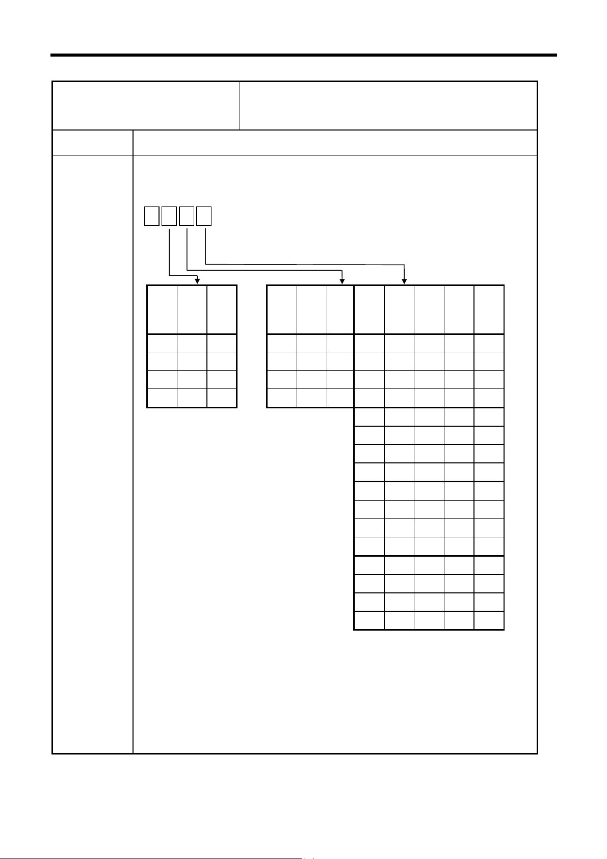
Error No. Details
0
The error number is displayed while each of the completion wait modes listed in the
table below is ON. It disappears when the mode is canceled.
0
Alarm
Unclamp
In dwell
No.
signal
wait
Note 2)
Alarm
execution
No.
Door
open
Note 1)
0 0 0
1
8
×
×
1
8
×
Waiting
Alarm
Waiting
for
spindle
position
to be
looped
×
No.
1
for
spindle
orienta-
tion to
complete
Waiting
for
cutting
speed
deceleration
2
Waiting
for rapid
traverse
deceleration
×
Waiting
for MSTB
completion
×
9
× ×
4
5
6
7
8
9
A
B
C
D
E
F
9
× ×
3
×
×
× ×
× × ×
×
×
×
×
× ×
× ×
× × ×
× × × ×
× ×
×
×
×
× ×
×
Note 1: This mode is enabled by the door interlock function.
Note 2: The system is waiting for the index table indexing unclamp signal to turn
ON or OFF
I - 13
Page 30
1. LIST OF ALARMS
×
×
∆
∆
1.3 SERVO ALARMS
1.3 SERVO ALARMS
These alarms describe errors in the servo system such as the servo drive amplifier‚ motor and encoder.
The alarm message‚ alarm No. and Axis Name will display on the alarm message. The No. of the axis
where the alarm occurred and the alarm No. will also display on the servo monitor screen. If several alarms
have occurred‚ a max. of two errors per axis will display on the servo monitor screen.
If “S”, “T”, “M” or “N” is displayed as an axis name on the alarm message screen, the error is a spindle
alarm.
Refer to the section “Spindle alarms”.
(The bold characters are the messages displayed on the screen.)
S
SERVO ALARM :
0 0
Axis name
Alarm No.
Alarm reset class
Alarm class
(Note 1) The alarm class and alarm reset class combinations are preset.
(Refer to the separate table for S02, S51 and S52.)
Alarm class Alarm reset class Resetting methods
S01 PR After removing the cause of the alarm, reset the
alarm by turning the NC power ON again.
S03 NR After removing the cause of the alarm, reset the
alarm by inputting the NC RESET key.
S04 AR After removing the cause of the alarm, reset the
alarm by turning the servo drive unit power ON
again.
(Note 2) The resetting method may change according to the alarm class.
For example, even if “S03 Servo error: NR” is displayed, it may be necessary to turn the NC
power ON again.
(Note 3) Refer to the spindle alarms if the axis name is “S”, “T”, “M” or “N”.
Alarm No. Name Meaning
10
11
12
13
14
15
Insufficient voltage PN bus voltage dropped to 200 V or lower.
Axis selection error The rotary switches for both axes are set to the same axis number
when using the 2-axis integrated amplifier. Otherwise, the switches
are set to an illegal value.
Memory error 1 An error occurred in a memory or FB IC by self-check to be made
during driver power-ON.
Software processing
error 1
Software processing
error 2
Memory error 2 Amplifier self-diagnosis error
The S/W process did not end within the specified time. (S/W
operation sequence or timing error)
The control IC is not operating correctly.
(The amplifier LED display will be “-”.)
I - 14
Page 31

1. LIST OF ALARMS
1.3 SERVO ALARMS
Alarm No. Name Meaning
16
Magnetic pole
position detection
An error occurred in the U, V, and W phases for polarity position
detection.
error
17
A/D converter error An error occurred in the A/D converter for current detection by
self-check to be made during driver power-ON.
A/D converter variables contain an abnormal value.
18
1A
Motor side detector:
Initial
communication error
Machine side
detector: Initial
The absolute position data was not sent properly with serial data
when the power was turned ON.
Initial communication with the detector could not be performed.
Initial communication with the detector cannot be performed in the
system that uses OHA25K-ET in the machine end detector.
communication error
1B
Machine side
detector: CPU error
In the high-speed serial detector connected to the machine end, an
error occurred in the data stored in an EEROM.
1
1C
Machine side
detector:
In the high-speed serial detector connected to the machine end, a
deteriorated LED was detected.
EEPROM/LED error
1D
1E
Machine side
detector: Data error
Machine side
detector: Memory
In the high-speed serial detector connected to the machine end, an
error occurred in a position within one rotation.
In the high-speed serial detector connected to the machine end, the
built-in thermal protector functioned.
error
1F
Machine side
detector:
In the high-speed serial detector connected to the machine end,
communication with the detector stopped.
Communication
error
20
21
22
24
Motor side detector:
No signal 1
Machine side
detector: No signal 2
LSI error LSI operation error
Grounding A grounded motor cable was detected. (Detected only in Ready ON
An abnormality was detected in the ABZ or UVW phase for the motor
end detector.
An abnormality was detected in the ABZ phase in a closed-loop
system.
state)
25
Absolute position
data lost
The absolute position data in the detector was lost.
(The backup voltage in the absolute position detector dropped. The
absolute position cannot be corrected.)
26
Unused axis error A power module error occurred in the axis set as [F] in the rotary
switch.
(Alarm issued only for 2-axis amplifier.)
27
Machine side
detector: CPU error
The CPU in the machine end absolute position detection linear scale
is malfunctioning.
2
I - 15
Page 32

1. LIST OF ALARMS
1.3 SERVO ALARMS
Alarm No. Name Meaning
28
Machine side
detector: Overspeed
The absolute position linear scale moved more than 45 mm/s during
initialization after the NC power was turned ON.
(Alarm output by linear scale.)
29
2A
2B
Machine side
detector: Absolute
position data error
Machine side
detector: Relative
position data error
Motor side detector:
CPU error 1
An error occurred in the scale or scale circuit for the absolute value
linear scale.
(Alarm is output from the linear scale.)
The absolute position linear scale has exceeded the maximum
movement speed.
(Alarm is output from the linear scale.)
Detector circuit error
In the motor end high-speed serial detector, an error occurred in the
data stored in an EEROM.
The scale CPU doesn’t operate properly.
(Alarm is output from the linear scale.)
2C
Motor side detector:
A deteriorated LED was detected in the detector.
EEPROM/LED error
2D
Motor side detector:
A detector position data error was detected.
Data error
2F
Motor side detector:
Communication
Communication with the detector stopped or receive data was
abnormal.
error
30
31
Over regeneration Overheating was detected in the regenerative resistor.
Overspeed A speed exceeding the motor’s tolerable rotation speed was
detected.
32
Power module
overcurrent
The overcurrent protector in the power module functioned.
An error occurred in the IPM used in the inverter. One of the
following factors can be considered.
(1) Overcurrent‚ (2) Overheat‚ (3) Drop in control power voltage‚ etc.
33
34
Overvoltage The PN bus voltage exceeded 400 V.
NC-DRV
An error occurred in the communication data from the NC.
communication:
CRC error
35
NC command error The movement command data from the NC is abnormally large in
amount.
36
NC-DRV
Communication from the NC stopped.
communication:
Communication
error
37
38
Initial parameter
error
NC-DRV
communication:
The servo parameter sent from the controller during initialization by
NC power-ON was illegal.
There was a protocol error in the communication with the NC.
(Frame error)
Protocol Error 1
39
NC-DRV
communication:
There was a protocol error in the communication with the NC.
(Information error)
Protocol Error 2
I - 16
Page 33

1. LIST OF ALARMS
1.3 SERVO ALARMS
Alarm No. Name Meaning
3A
3B
3C
Overcurrent The motor drive current is too large.
Power module
overheat
Regeneration circuit
An overheat in the IPM used for the servo drive’s main circuit was
detected.
A regeneration transistor or resistor error was detected.
error
42
Feedback error 1 A feedback pulse skip or Z-phase error occurred in the position
detector.
43
Feedback error 2 There is an excessive difference in the feedback amount between
the motor end detector and the machine end detector during a
closed loop. An FB IC error was also detected during semi-closed
loop.
46
48
49
Motor overheat The motor overheated.
Motor side detector:
CPU error 2
Motor side detector:
Overspeed
When using the linear servo system, the CPU in the absolute
position linear scale is malfunctioning.
When using the linear servo system, the absolute position linear
scale detected a speed exceeding 45m/s when the CNC power was
turned ON.
4A
Motor side detector:
Absolute position
When using the linear servo system, the absolute position linear
scale detected an error in the scale or scale circuit.
data error
4B
4F
Motor side detector:
Relative position
data error
Instantaneous
When using the linear servo system, the absolute position linear
scale detected a speed exceeding the maximum movement speed of
the absolute position scale.
A momentary power interrupt of 50 ms or longer was detected.
power interruption
50
Overload 1 Excessive loads were applied for an interval exceeding the specified
time.
The load level of the servomotor or servo driver can be calculated
from the motor current. This load level has reached the overload
level that is specified by the overload detection level (sv022: OLL)
and overload-time constant (sv021: OLT).
51
Overload 2 Excessive loads are applied, exceeding the specified time.
A current command exceeding 95% of the maximum driver capacity
continued for 1.0 second or more.
52
Excessive error 1 The difference between the ideal and actual positions has exceeded
parameter setting value
sv023: OD1 (or sv053: OD3) when the servo was turned ON.
53
Excessive error 2 The difference between the ideal and actual positions has exceeded
parameter setting value
sv026: OD2 when the servo was turned OFF.
I - 17
Page 34

1. LIST OF ALARMS
1.3 SERVO ALARMS
Alarm No. Name Meaning
54
Excessive error 3 When an excessive error or alarm 1 is detected, no motor current
flows. This error occurs when the power cable is loose or
disconnected or no voltage is applied to the bus.
55
External emergency
stop error
No contactor interrupt command is issued in 30 seconds after an
external emergency stop signal is input.
Check the settings for the emergency stop input signal and sv036
external emergency stop.
58
59
5A
5F
Collision detection 1:
G0
Collision detection 1:
G1
Collision detection 2 An interference or system 2 error was detected.
External contactor
An interference or system 1 error was detected in G0 modal (rapid
traverse feed) mode.
An interference or system 1 error was detected in G1 modal (cutting
speed) mode.
An outside contact fused.
welding
61
62
Power module
overcurrent
Frequency error A “power frequency error” was detected in the power supply unit.
The “regenerative overcurrent” alarm was generated on the power
supply unit side. (Alarm “1” on the power supply unit.)
(Alarm “2” on the power supply unit.)
63
65
Supplementary
regeneration error
Rush relay error The “rush current error” alarm was generated on the power supply
The “compensating regenerative error” alarm was generated on the
power supply unit side. (Alarm “3” on the power supply unit.)
unit side. (Alarm “5” on the power supply unit.)
67
Phase interruption The “open phase alarm” was generated on the power supply unit
side. (Alarm “7” on the power supply unit.)
68
Watchdog The “watch dog” alarm was generated on the power supply unit side.
(Alarm “8” on the power supply unit.)
69
Grounding The “motor ground fault” alarm was generated on the power supply
unit side. (Alarm “9” on the power supply unit.) For details refer to the
descriptions for the power supply unit’s alarms.
6A
External contactor
welding
“External contactor deposition” was detected on the power supply
unit side. (Alarm “A” on the power supply unit.)
I - 18
Page 35

1. LIST OF ALARMS
1.3 SERVO ALARMS
Alarm No. Name Meaning
6B
Rush relay welding “Rush relay deposition” was detected on the power supply unit side.
(Alarm “b” on the power supply unit.)
6C
Main circuit error “Main circuit error” was detected on the power supply unit side.
(Alarm “c” on the power supply unit.)
6D
Parameter error “Parameter value abnormal” was detected on the power supply unit
side. (Alarm “d” on the power supply unit.)
6E
Power supply PCB
combination error
Memory error “Memory error” was detected on the power supply unit side. (Alarm
An incorrect power PCB and control PCB combination was detected.
(Alarm “d” on the power supply unit.) (MDS-CH-CV Series only)
“E” on the power supply unit.)
6F
Power supply error • “AD converter error” was detected on the power supply unit side.
• It was recognized that the power supply is not connected. (Alarm
“F” on the power supply unit.)
71
Instantaneous
power
“Momentary power failure detection” alarm is generated on the
power supply unit side. (Alarm “H” on the power supply unit.)
interruption/External
emergency stop
73
Over regeneration “Overregeneration” alarm is generated on the power supply unit
side. (Alarm “J” on the power supply unit.)
74
75
Regenerative
resistor overheat
Overvoltage “Overvoltage” alarm is generated on the power supply unit side.
“Regeneration resistor overheated” alarm is generated on the power
supply unit side. (Alarm “K” on the power supply unit.)
(Alarm “L” on the power supply unit.)
76
77
7F
External emergency
stop setting error
Power module
overheat
Drive unit power
supply reclose
request
“External emergency stop setting abnormal” alarm is generated on
the power supply unit side. (Alarm “M” on the power supply unit.)
“Power module or PC board overheated” alarm is generated on the
power supply unit side. (Alarm “n” on the power supply unit.)
An error was detected when the high-gain mode and normal mode
was selected.
Turn the amplifier power ON again.
If this alarm is detected even after the amplifier power is turned ON
again after the alarm 7F is detected, there is an error in the
EEPROM.
Refer to the MELDAS AC Servo Maintenance Manual for details.
80
Detector converting
unit 1: Connection
The MDS-B-HR connected to the motor end detected an incorrect
connection or broken cable.
error
I - 19
Page 36

1. LIST OF ALARMS
1.3 SERVO ALARMS
Alarm No. Name Meaning
81
Detector converting
unit 1:
The MDS-B-HR connected to the motor end detected an error in the
communication with the absolute position detection scale.
Communication
error
83
Detector converting
unit 1: Judgment
The MDS-B-HR connected to the motor end could not judge the
connected scale's analog wave cycle.
error
84
85
86
Detector converting
unit 1: CPU error
Detector converting
unit 1: Data error
Detector converting
unit 1: Magnetic Pole
The CPU for the MDS-B-HR connected to the motor end is not
operating correctly.
An error was detected in the analog interpolation data for the
MDS-B-HR connected to the motor end.
An error was detected in the magnetic pole data of the MDS-B-HR
connected to the motor end.
error
88
89
Watchdog Servo system operation is abnormal.
Detector converting
unit 2: Connection
The MDS-B-HR connected to the machine end detected an incorrect
connection or broken cable.
error
8A
Detector converting
unit 2:
The MDS-B-HR connected to the machine end detected an error in
the communication with the absolute position detection scale.
Communication
error
8C
Detector converting
unit 2: Judgment
The MDS-B-HR connected to the machine end could not judge the
connected scale's analog wave cycle.
error
8D
8E
Detector converting
unit 2: CPU error
Detector converting
unit 2: Data error
The CPU for the MDS-B-HR connected to the machine end is not
operating correctly.
An error was detected in the analog interpolation data for the
MDS-B-HR connected to the machine end.
I - 20
Page 37

1. LIST OF ALARMS
A
A
1.3 SERVO ALARMS
An error was found in the
S02 INIT PARAM ERR
∆∆∆∆
xis name
larm No. (parameter No.)
(Note) Refer to the spindle alarms if the axis name is “S”, “T”, “M” or
“N”.
Alarm No. Details Remedy
2201 – 2264
2301
2302
2303
2304
2305
The servo parameter setting data is illegal.
The alarm No. is the No. of the servo
parameter where the error occurred.
The number of constants to be used in the
following functions is too large:
• Electronic gears
• Position loop gain
• Speed feedback conversion
High-speed serial incremental detector
Parameters for absolute position detection
are set to ON during OSE104 and OSE105
connection.
Set the parameters for absolute position
detection to OFF.
To detect an absolute position, replace the
incremental specification detector with an
absolute position detector.
No servo option is found.
The closed loop (including the ball screwend detector) or dual feedback control
function is an option.
No servo option is found.
The SHG control function is an option.
No servo option is found.
The adaptive filtering function is an option.
Check the descriptions for the appropriate
parameters and correct them.
Check that all the related parameters are
specified correctly.
sv001:PC1, sv002:PC2, sv003:PGN1
sv018:PIT, sv019:RNG1, sv020:RNG2
Check that all the related parameters are
specified correctly.
sv017:SPEC, sv025:MTYP
Check that all the related parameters are
specified correctly.
sv025:MTYP/pen
sv017:SPEC/dfbx
Check that all the related parameters are
specified correctly.
sv057:SHGC
sv058:SHGCsp
Check that all the related parameters are
specified correctly.
sv027:SSF1/aflt
parameters transmitted from the
controller to the spindle amplifier
when the power was turned ON.
Remove the cause of the alarm,
and then reset the alarm by
turning the controller power OFF
once.
I - 21
Page 38
1. LIST OF ALARMS
A
A
A
A
1.3 SERVO ALARMS
A warning appears if a
S51 PARAMETER ERROR
∆∆∆∆
xis name
larm No.
(parameter No.)
(Note) Refer to the spindle alarms if the axis name is “S”, “T”, “M” or
“N”.
Alarm No. Details Remedy
2201 – 2264
Servo parameter setting data is illegal.
The alarm No. is the No. of the servo
parameter where the warning occurred.
Check the descriptions for the appropriate
parameters and correct them.
parameter set outside the
tolerable range is set.
Illegal settings will be ignored.
This alarm will be reset when the
correct value is set.
The servo warning is displayed.
S52 SERVO WARNING 0 0 ∆∆
xis name
larm No.
(Warning No.)
(Note) Refer to the spindle alarms if the axis name is “S”, “T”, “M” or
“N”.
Alarm No. Name Meaning
90
91
92
93
96
97
9B
9C
Detector: Initial
communication
error
Detector:
Communication
error
Detector: Protocol
error
Initial absolute
position fluctuation
Scale feedback
error
Scale offset error An error occurred in the offset data to be read during initialization by
Detector
converting unit:
Magnetic pole shift
warning
Detector
converting unit:
Magnetic pole
warning
Initial communication with the absolute position linear scale cannot be
performed.
An error occurred in communication with the detector in the absolute
position detector.
An error occurred in the data from the detector in the absolute position
detector.
The absolute position data fluctuated when the power was turned ON
so the absolute value counter could not be set.
There is an excessive difference in the feedback amount between the
motor end detector and the MP scale in the absolute position detector.
NC power-ON in the absolute position detector of the MP scale.
When using the linear servo system, an error was detected in the
magnetic pole shift amount set in sv028.
When using the linear servo system, an error was detected in the
magnetic pole data of the MDS-B-HR connected to the MAIN side
after the Z phase was passed.
I - 22
Page 39

1. LIST OF ALARMS
1.3 SERVO ALARMS
Alarm No. Name Meaning
9E
9F
E0
E1
Absolute position
detector:
Revolution counter
error
Battery voltage
drop
Over regeneration
warning
Overload warning An 80% level of the overload 1 alarm was detected. This is not an
An error occurred in the rotation counter in the detector. An error
occurred in the rotation counter in
OSE104/OSA104/OSE105/OSA105/OSE104-ET/OSA104-ET/OSE1
05-ET/OSA105-ET. The absolute position cannot be corrected.
The voltage of the battery supplying to the absolute value detector
dropped.
An 80% level of the regeneration alarm was detected. (The
regeneration alarm may occur if operation is continued.)
alarm so the servo will not turn OFF‚ but if operation is continued‚
overload 1 alarm may occur.
E3
Absolute position
There is a difference between absolute and relative position data.
counter warning
E4
Set parameter
A parameter setting exceeding the setting range was set.
warning
E6
Control axis
A control axis removal command has been issued. (Status display)
detachment
warning
E8
Excessive
supplementary
The auxiliary regeneration cycle was too high in the power supply unit.
(Alarm “o” from the power supply unit)
regeneration
frequency
E9
Instantaneous
power interruption
A momentary power interrupt of 25 to 50 ms occurred. (Alarm “p” from
the power supply unit.)
warning
EA
In external
emergency stop
The power supply enters an emergency stop state by receiving the
stop signal from the NC. (Alarm “q” from the power supply unit)
state
EB
Over regeneration
warning
An excessive-regeneration alarm was generated from the power
supply unit. (Alarm “r” from the power supply unit.)
I - 23
Page 40
1. LIST OF ALARMS
×
×
∆
∆
1.4 SPINDLE ALARMS
1.4 SPINDLE ALARMS
These alarms describe errors in the spindle system such as the spindle amplifier‚ motor and encoder.
The alarm message, alarm number, and axis name (S: 1st spindle, T: 2nd spindle, M: 3rd spindle, N: 4th
spindle) will display on the alarm message screen. If several alarms have occurred, the number of the
alarm that occurred last and the other alarm numbers will display on the spindle monitor screen for
confirmation. If an axis name other than “S”, “T”, “M” and “N” is displayed, the alarm is a servo alarm.
Refer to the section “Servo alarms”. (The bold characters are the messages displayed on the screen.)
S
SERVO ALARM :
0 0
Axis name
Alarm No.
Alarm reset class
Alarm class
(Note 1) The alarm class and alarm reset class combinations are preset.
(Refer to the separate table for S02, S51 and S52.)
Alarm class Alarm reset class Resetting methods
S01 PR After removing the cause of the alarm, reset the
alarm by turning the NC power ON again.
S03 NR After removing the cause of the alarm, reset the
alarm by inputting the NC RESET key.
S04 AR After removing the cause of the alarm, reset the
alarm by turning the servo drive unit power ON
again.
(Note 2) The resetting method may change according to the alarm class.
For example, even if “S03 Servo error: NR” is displayed, it may be necessary to turn the NC
power ON again.
(Note 3) Refer to the servo alarms if the axis name is other than “S”, “T”, “M” and “N”.
Alarm No. Name Meaning
12
13
16
17
20
Memory error 1 A check sum or RAM check error occurred in the ROM of the spindle
drive’s control card.
Software
processing error 1
Magnetic pole
position detection
error
A/D converter error The AD converter for current detection did not function normally
Motor side
detector: No signal
1
The S/W process did not end within the specified time.
The start signal was input before the Z-phase of the magnetic pole
position was automatically adjusted.
Or, the number of initial magnetic pole estimation retry times (10 times
or more) was exceeded.
(After replacing the spindle amplifier, set parameter (SP205: ZCHS) to
1 from 0, carry out Z phase automatic adjustment, and then turn the
power ON again.)
during initialization.
A signal was not input from the PLG‚ or was not at a normal level.
I - 24
Page 41

1. LIST OF ALARMS
1.4 SPINDLE ALARMS
Alarm No. Name Meaning
21
Machine side
detector: No signal
A signal was not input from the spindle encoder (for orient‚ C axis)‚ or
was not at a normal level.
2
23
Excessive speed
error 1
The command speed and motor speed difference was above the
specified value‚ and the state continued for the specified time.
This may also occur when the coil changeover contactor is not the
specified contactor.
30
31
32
Over regeneration Overheating was detected in the regenerative resistor.
Overspeed The motor speed exceeded 115% of the set max. speed.
Power module
overcurrent
A current exceeding the specified value flowed to the spindle drive’s
main circuit.
This may also occur when the coil changeover contactor is not the
specified contactor.
33
Overvoltage The bus voltage in the driver exceeded 400V.
This may also occur when the coil changeover contactor is not the
specified contactor.
34
NC-DRV
A CRC error occurred in the communication data from the controller.
communication:
CRC error
35
NC command error The movement command data from the controller is abnormally high
during position control.
36
NC-DRV
The periodic data transmission from the controller was stopped.
communication:
Communication
error
37
38
Initial parameter
error
NC-DRV
communication:
The servo parameter sent from the controller during initialization of the
driver was illegal.
There was a protocol error in the communication with the controller.
(Frame error)
Protocol error 1
39
NC-DRV
communication:
There was a protocol error in the communication with the controller.
(Information error)
Protocol error 2
3A
Overcurrent The command current reached the spindle drive's maximum output
current and continued for one second or more.
3B
Power module
An overheat in the IPM used for the driver’s main circuit was detected.
overheat
3D
Spindle motor
locked
A state in which the motor speed did not reach 45r/min or more even
when the maximum torque command value reached the time set in the
parameter SP239 (3 seconds when set to 0) was detected.
3E
Spindle speed
overrun
1. A state in which the motor was continuously accelerated even
when the speed feedback exceeded 112.5% (detection speed) of
the commanded speed was detected. (Note that if a speed less
than the parameter SP237 (1000r/min when set to 0) setting is
commanded, the detection speed will be the speed command
value + SP237∗1.125.)
2. Motor rotation exceeding the value set with parameter SP206
(when set to 0: 10 deg.) was detected even though the speed
command was 0 (including when stopped during position control).
I - 25
Page 42

1. LIST OF ALARMS
1.4 SPINDLE ALARMS
Alarm No. Name Meaning
3F
Excessive speed
error 2
The state in which the speed range set by parameter SP238 (30%
when set to 0) was exceeded while rotating at a constant speed with
speed control exceeded the time set in parameter SP239 (3 seconds
when set to 0).
40
41
Detector selection
unit switching error
Detector selection
unit
The procedure for changing the signal during use of the TK unit is
wrong.
Communication with the TK unit during use of the TK unit was
incorrect.
communication
error
42
Feedback error 1 1. A PLG error was detected during PLG automatic compensation.
2. The correct Z phase was not detected even when the motor
rotated several times during Z phase automatic adjustment.
3. An abnormal number of feedback pulses was continuously
detected during normal operation.
43
Feedback error 2 A deviation occurred in the feedback from the spindle encoder and
motor built-in encoder.
44
Inappropriate
winding selected
When using the coil changeover motor, the C axis mode was entered
when the H coil or M coil was selected.
for C axis
46
Motor overheat The motor overheated and the thermal protector functioned during an
overload or when the motor cooling blower stopped.
4E
NC command
mode error
The spindle control mode was selected several times.
(If the input was unexpected, the mode will return to the speed control
mode, and an alarm will occur.)
50
Overload 1 The time that the motor current exceeded the overload detection level
exceeds the detection time constant.
51
Overload 2 The motor output reached the overload level set with the overload
detection level and detection time constant.
52
Excessive error 1 The position tracking error exceeded the specified value during
position loop operation.
5C
Orientation
feedback error
When orientation was completed, the error between the command
and feedback exceeded the value set in the parameters. If the number
of orientation retry times parameter SP118 is set, “S52 SERVO
WARNING 00A9” will occur, and then this alarm will occur. (An alarm
will occur if the error exceeds SP114: OPER. This cannot be detected
when using magnetic sensor orientation, so set SP114 to 0.)
I - 26
Page 43

1. LIST OF ALARMS
A
A
A
A
1.4 SPINDLE ALARMS
Alarm No. Name Meaning
5D
5E
61 – 6F
88
S02 INIT PARAM ERR
(Note) Refer to the servo alarms if the axis name is other than “S”,
“T”, “M” and “N”.
Alarm No. Details Remedy
3201 – 3584
Speed monitoring:
Input mismatch
Speed monitoring:
Feedback speed
error
Power supply
alarm
Watchdog 88 is the watch dog alarm. Refer to the section “Servo alarms” for
∆∆∆∆
Parameter error
A parameter value not within the
tolerable range was set. The alarm No. is
the No. of the spindle parameter where
the error occurred.
S51 PARAMETER ERROR
(Note) Refer to the servo alarms if the axis name is other than “S”,
“T”, “M” and “N”.
This occurs if the door state of the “DI input (CN9 10-20)” and the
“data input (control input 4-bit D)” signal from the NC do not match.
(Occurs if the state does not match for three seconds.)
This occurs if the door is opened when the spindle speed is higher
than the speed set in parameter SP223: SPDV.
The codes 60 to 6F are power supply alarms. The power supply
alarms will be displayed as alarms of the axis to which the power
supply is connected. Refer to the section “Servo alarms” for details.
details.
An error was found in the
∆∆∆∆
xis name
larm No.
(parameter No.)
(parameter No.)
• Confirm the spindle parameter for the No.
displayed as an error.
Refer to Spindle Drive Maintenance Manual’s
Alarm No. 37.
xis name
larm No.
parameters transmitted from the
controller to the spindle amplifier
when the power was turned ON.
Remove the cause of the alarm,
and then reset the alarm by
turning the controller power OFF
once.
A warning appears if a
parameter set outside the
tolerable range is set.
Illegal settings will be ignored.
This alarm will be reset when the
correct value is set.
Alarm No. Details Remedy
3201 – 3584
Parameter warning
A parameter value not within the
tolerable range was set.
The alarm No. is the No. of the spindle
where the warning occurred.
I - 27
• Confirm the details of the spindle parameter
for which the No. is displayed.
Page 44

1. LIST OF ALARMS
A
A
1.4 SPINDLE ALARMS
The spindle warning is
S52 SERVO WARNING 0 0 ∆∆
xis name
displayed.
larm No.
(Warning No.)
(Note) Refer to the servo alarms if the axis name is other than “S”,
“T”, “M” and “N”.
Alarm No. Details Remedy
A9
E0
E1
E4
Orientation feedback warning
The system is retrying when an
orientation feedback error occurs.
(When SP118: ORCT is set to 0, an
alarm (5C) will occur instead of the
warning.)
Over regeneration warning
A level of 80% of the excessiveregeneration alarm was detected
(continuing the operation may cause the
excessive-regeneration alarm).
Overload warning
The time that the motor current exceeded
the overload detection level was 80% or
more of the detection time constant.
Set parameter warning
A parameter exceeding the setting range
was set. The illegal parameter will be
ignored‚ and the value before the illegal
parameter setting will be retained.
Check the speed detector or encoder shield
treatment, and for wire breakage.
Check the phase of the A, B and Z phases.
(Adjust the waveform)
Refer to the Spindle Drive Maintenance
Manual.
Refer to the Spindle Drive Maintenance
Manual.
Confirm the spindle parameter.
I - 28
Page 45

1. LIST OF ALARMS
A
1.5 MCP ALARM
1.5 MCP ALARM
An error has occurred in the drive amplifier and other interfaces. (The bold characters are the messages
displayed on the screen.)
Y02 SYSTEM ALARM
Error No. Details Remedy
0050
0051
Y03 AMP. UNEQUIPPED
The amplifier is not correctly
connected
Error No. Details
Alphabet
(axis name)
1 – 4
S
T
Background error The software or hardware may be damaged.
0000 CRC error
0001 CRC error (2 continuous times)
0002 Reception timing error
××03
××04
Servo axis amplifier not mounted
PLC axis amplifier not mounted
No.1 spindle axis not mounted
No.2 spindle axis not mounted
An error occurred in the data transmitted between the MCP and amplifier
after the power was turned ON.
Contact the service center.
communication error has occurred between
(10 times/910.2 ms)
(2 continuous times)
Data ID error
(2 continuous times)
××: Axis No.
No. of reception frames error
(2 continuous times)
××: Axis No.
Check the amplifier mounting state.
• Check the end of the cable wiring.
• Check the cable for broken wires.
• Check the connector insertion.
• The amplifier input power is not being input.
• The amplifier axis No. switch is illegal.
the controller and amplifier.
• Take measures against noise.
• Check that the communication cable
connector between the controller and
amplifier and one between the amplifiers are
tight.
• Check whether the communication cable
between the controller and amplifier and
one between the amplifiers are
disconnected.
• A driving amplifier may be faulty. Take a
note of the 7-segment LED contents of each
driving amplifier and report to the Service
Center.
Y05 INIT PARAM ERR
: Error parameter number
Details Remedy
There is a problem in the value set for the number of axes or
the number of systems.
↑
Check the value set for the corresponding
parameters.
#1001 SYS_ON
#1002 axisno
#1039 spinno
I - 29
Page 46

1. LIST OF ALARMS
1.5 MCP ALARM
Y06 mcp_no ERROR
There are differences in the MCP and axis parameters when the NC power
is turned ON.
Error No. Details Remedy
0001
0002
0003
0004
There is a skipped number in the channels.
The random layout setting is duplicated.
The amplifier fixed setting “0000” and
random layout setting “∗∗∗∗” are both set.
The spindle/C axis “#3031 mcp_no” and
Check the values set for the following
parameters.
#1021 mcp_no
#3031 smcp_no
#3032 mbmcp_no
“#3032 smcp_no” are set to the same
values.
0005
A random layout is set for the “#1154 pdoor”
=1 two-system.
0006
The channel No. parameter is not within the
setting range.
Y51 PARAMETER ERROR
An error occurred in a parameter that causes an alarm while the control
axis was operating.
Error No. Details Remedy
1
LN FEED ABNL (Linear feed abnormal)
• Check “#2004 G0tL”.
The time constant has not been set or the
setting exceeded the setting range.
2
CT FEED ABNL (Cutting feed abnormal)
• Check “#2007 G1tL”.
The time constant has not been set or the
setting exceeded the setting range.
3
DLY F-F ABNL (Delayed fast feed abnormal)
• Check “#2005 G0t1”.
The time constant has not been set or the
setting exceeded the setting range.
4
DLY CUTG ABNL (Delayed cutting feed
• Check “#2008 G1t1”.
abnormal)
The time constant has not been set or the
setting exceeded the setting range.
9
12
GRID SPACE ERROR • Check “#2029 grspc”.
SYNCHRONOUS TAP CYCLE
ACCELERATION/DECELERATION TIME
• Check spindle parameters #3017 stapt1 to
#3020 stapt4.
CONSTANT ERROR
The time constant has not been set or the
setting exceeded the setting range.
15
LN SKIP ABNL (Linear skip abnormal)
• Check “#2102 skip_tL”.
The time constant has not been set or the
setting exceeded the setting range.
16
DLY SKIP ABNL (Delayed skip abnormal)
• Check “#2103 skip_t1”.
The time constant has not been set or the
setting exceeded the setting range.
101
ROTARY AXIS GEAR RATIO EXCESSIVE
• Check “#2201 PC1” and “#2202 PC2”.
(ABSOLUTE POSITION DETECTION)
I - 30
Page 47

1. LIST OF ALARMS
1.5 MCP ALARM
Y90 SP. NON SIGNAL
Alarm No. Details Remedy
0001 – 0007
(Alarm No.)
0
0
There is an error in the spindle encoder
signal.
The data transmission to the servo amplifier
and spindle amplifier is stopped when this
error occurs.
No.1 spindle
No.2 spindle
Alarm No.
1
2
3
4
5
6
7
Z open
phase
B open
phase
×
×
× ×
×
× ×
× ×
× × ×
• Check the spindle encoder’s feedback
cable and the encoder.
A open
phase
I - 31
Page 48

1. LIST OF ALARMS
1.6 SYSTEM ALARMS
1.6 SYSTEM ALARMS
The following messages are displayed with the register at the time when the error occurred if the system
stops due to a system error.
Message Details Remedy
Parity error RAM error • Write down the displayed register‚ and
Bus error A non-existing memory was accessed. contact the service center.
Zero divide The division with a 0 denominator was
attempted.
Watch dog
error
Illegal
exception
Address error An illegal memory was accessed.
Illegal
instruction
Stack
overflow
The software process is not functioning
correctly.
The alarm was caused by an illegal
software function not listed above.
The software process is not functioning
correctly.
Z31 DATA SERVER ERROR
Warning No.
Warning No. Explanation
0001 Socket open error (socket)
0002 Socket bind error (bind)
0003 Connection wait queue error (listen)
0004 Connection request acceptance error (accept)
0005 Data receive error (socket error)
0006 Data receive error (data shortage or disconnection)
0007 Data send error (socket error)
0008 Data send error (data shortage or disconnection)
000A Socket close error (close)
Note: If warning No. 0001, 0002, 0003, or 000A is displayed, set the parameters, then turn power OFF and turn it
ON again.
Message Details Remedy
Z40
FORMAT
NOT MET
This appears when the parameter MemVal
is formatted at 0, and MemVal is set to 1.
↑
• Either return the MemVal setting, or format
and restart.
I - 32
Page 49

1. LIST OF ALARMS
1.6 SYSTEM ALARMS
The bold characters are the messages displayed on the screen.
Message Details Remedy
Z51 EE ROM
ERROR
000x
Z52 BATTERY
FAULT
Z53 TEMP.
OVER
This occurs when the parameters
were not correctly written into the
EEROM.
Formatting of the machine
manufacturer macro program area did
not end correctly.
The machine manufacturer macro
program was not written into the
FROM correctly.
<Type>
Z51 ROM error 0001: Open error
Z51 ROM error 0002: Erase error
Z51 ROM error 0003: Write error
Z51 ROM error 0004: Verify error
The voltage of the battery inserted in
the NC control unit has dropped. (The
battery used to save the internal data)
The controller or operation board
temperature has risen above the
designated value. (Note 1)
• If the same alarm is output by the same
operation, the cause is an H/W fault.
Contact the Service Center.
• Reformat the area.
• Write to the FROM again.
• Replace the battery of the NC control unit.
• After treating the battery‚ check the
machining program‚
• Cooling measures are required.
Turn OFF the controller power‚ or lower
the temperature with a cooler‚ etc.
Z55 RIO NOT
CONNECT
Z57 SYSTEM
WARNING
Z58 ROM WR
UNFIN
This occurs when an error occurs in
the communication between the
controller and remote l/O unit.
• Cable breakage
• Remote l/O unit fault
• Power supply to remote l/O unit fault
(Note 2)
The program memory capacity setting
value cannot be formatted.
The expansion cassette (HR437) is
not mounted after formatting.
An expansion cassette different from
the expansion cassette (HR437)
mounted during formatting is
mounted.
(Note 3)
The machine manufacturer macro
program was not written to the FROM
after being registered, edited, copied,
condensed, merged, the number
changed, or deleted.
• Check and replace the cables.
• Replace the remote I/O unit.
• Check the power supply. (existence of
supply‚ voltage)
Check the state of the following items.
• Program memory capacity
• Status of expansion cassette (HR437)
mounting
• APLC open option
• Write the machine manufacturer macro
program to the FROM.
* If the operations, such as editing, done
while the NC power was OFF can be
invalidated, the program does not need to
be written to the FROM.
I - 33
Page 50

1. LIST OF ALARMS
1.6 SYSTEM ALARMS
Message Details Remedy
Z59 TIME
CONSTANT
CAUTION
If the battery low warning is issued, save the machining programs, tool data and parameters in
an input/output device, and then replace the battery. When the battery alarm is issued, the
machining programs, tool data and parameters may be destroyed. Reload the data after
replacing the battery.
Do not replace the battery while the power is ON.
Do not short circuit, charge, heat, incinerate or disassemble the battery.
Dispose of the spent battery following local laws.
Note 1: Temperature warning
If the alarm is displayed when an overheat alarm is detected‚ the overheat signal will be output
simultaneously. If the machine is in automatic operation‚ the operation will be continued‚ but
restarting will not be possible after resetting or stopping with M02/M30. (Starting will be possible
after block stop or feed hold.) The alarm will be reset and the overheat signal will turn OFF when
the temperature drops below the specified temperature.
Acceleration and deceleration time
constants are too large.
(This alarm is output at the same
time as “T02 FEED HOLD 0206.”)
• Increase the value specified as the #1206
G1bF parameter.
• Decrease the value specified as the
#1207 G1btL parameter.
• Lower the feedrate.
Z53 TEMP. OVER 000x
↑
0001 : The temperature in the controller is high.
0002 : The temperature around the communication terminal
(setting and display unit) is high.
0003 : The temperature in the controller and around the communication
terminal (setting and display unit) is high.
The ambient temperature must be lowered immediately when a “Z53 TEMP.OVER” alarm occurs‚ but if
machining must be continued‚ the alarm can be invalidated by turning the following parameter OFF.
7 6 5 4 3 2 1 0
PLC parameter bit selection #6449
Communication terminal
(setting and display unit) 0: Detection invalid
Controller 1: Detection valid
I - 34
Page 51
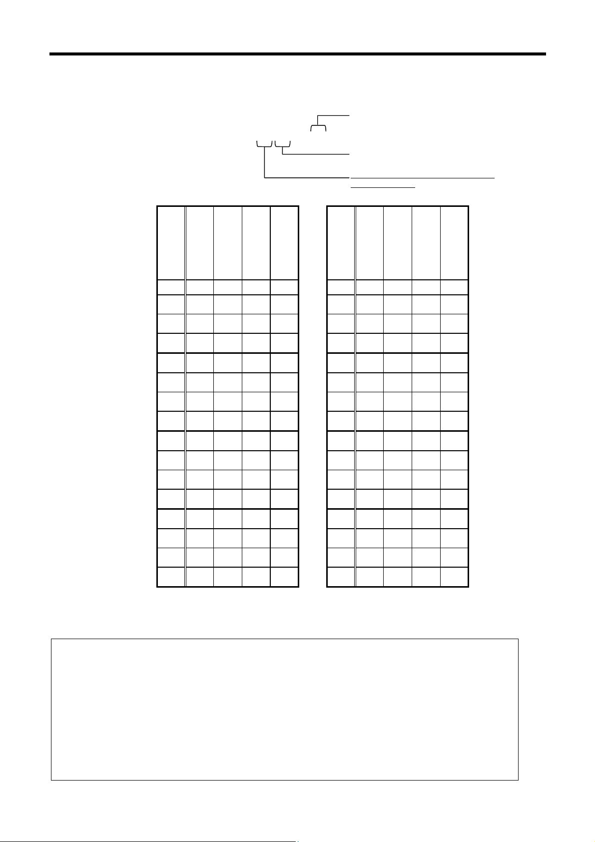
1. LIST OF ALARMS
1.6 SYSTEM ALARMS
Note 2: RIO communication interrupt
If communication between the control unit and remote I/O unit fails, the alarm and remote I/O unit
number are displayed.
Z55 RIO NOT CONNECT
(a) and (b) above indicate the following matters.
Alarm
RIO
(seventh
station)
RIO
(sixth
station)
number
0 0
1 × 1
(a)(b)
↓ ↓
RIO
(fifth
station)
RIO
(fourth
station)
0 0
Board connection remote I/O
communication interrupted station
Remote I/O 1st system communication
interrupted station
Remote I/O 2nd system communication
interrupted station
Alarm
RIO
RIO
RIO
number
(third
station)
(second
station)
(first
station)
RIO
(0th
station)
×
2
3
4
5
6
7
8
×
9
×
A
×
B
×
C
× ×
D
× ×
E
× ×
F
× ×
This applies for both the remote I/O 1st system communication interrupted station and board connection
remote I/O communication interrupted station.
Note 3: System warning
Z57 SYSTEM WARNING 00xx 0000
↑
001x : When the expansion cassette (HR437) is not mounted, a program
memory capacity exceeding 1280m was designated.
002x : When the APLC open option was validated, 5120m was
designated
for the program memory capacity.
00x1 : After formatting the program memory capacity to 1280m or more,
the expansion cassette (HR437) was removed, or an expansion
cassette (HR437) not used during formatting was mounted.
×
×
×
×
×
×
×
×
8
×
×
×
×
2
3
×
4
C
5
×
6
7
×
×
9
×
A
B
×
×
×
×
×
D
×
E
F
×
×
×
×
×
× ×
×
×
×
×
×
× ×
×
× ×
×
×
×
×
×
× ×
×
×
×
I - 35
Page 52

1. LIST OF ALARMS
1.7 ABSOLUTE POSITION DETECTION SYSTEM ALARMS
1.7 ABSOLUTE POSITION DETECTION SYSTEM ALARMS
Z70 ABS. ILLEGAL
(Error No.) (Axis name)
Error No. Details Remedy
0001
0002
0003
0004
0005
0080
0101
0106
Note: To release alarm “Z70 ABS. ILLEGAL”, enter the parameter data output when establishing the
Zero point initialization is
incomplete.
Otherwise, the spindle was
removed.
The absolute position
reference point data saved in
the NC has been destroyed.
The parameters used to detect
the absolute position have
been changed.
#1003 iunit #2201 PC1
#1016 iout #2202 PC2
#1017 rot #2218 PIT
#1018 ccw #2219 RNG1
#1040 M_inch #2220
RNG2
#2049 type #2225 MTYP
The zero point initialization
point is not at the grid position.
Restoration was possible with
parameter input in the above
No.0002 state.
The absolute value data was
lost, because the multi-rotation
counter data in the detector
was incorrect, etc.
The power was turned ON
again after the servo alarm No.
25 displayed.
The power was turned ON
again after the servo alarm No.
E3 displayed.
absolute position and turn ON the power again. For the rotation axis, however, the alarm cannot
be released by entering the parameter data.
This error is displayed if the absolute position data is lost in
the absolute position detection system.
Alarm reset
Complete zero point
initialization.
Input the parameters.
If the reference point
data cannot be
restored‚ perform
zero point
initialization.
Correctly set the
parameters. Turn the
power on again‚ and
perform zero point
initialization.
Reperform zero point
initialization.
Turn the power on
again‚ and operation
will be possible.
Replace the detector
and complete zero
point initialization.
Reperform zero point
initialization.
Reperform zero point
initialization.
Zero point
initialization
Required
(Required)
Required
Required
Not required
Required
Required
Required
when
power is
turned OFF
− −
− −
− −
− −
− −
−
−
−
Servo
alarm No.
(9E)
etc.
(25)
(E3)
I - 36
Page 53

1. LIST OF ALARMS
1.7 ABSOLUTE POSITION DETECTION SYSTEM ALARMS
Z71 DETECTOR ERROR
(Error No.) (Axis name)
Error No. Details Remedy
0001
The backup voltage in the
absolute position detector
dropped.
Replace the battery‚
check the cable
connections‚ and
check the detector.
Turn the power ON
again‚ and perform
zero point
initialization.
0003
Communication with the
absolute position detector
was not possible.
Check and replace the
cables‚ card or
detector. Turn the
power ON again‚ and
perform zero point
initialization.
0004
The absolute position
data fluctuated when
establishing the absolute
position.
Check and replace the
cables‚ card or
detector. Turn the
power ON again‚ and
perform zero point
initialization.
0005
An error was found in the
serial data from the
absolute position
detector.
Check and replace the
cables‚ card or
detector. Turn the
power ON again‚ and
perform zero point
initialization.
0006
0007
Servo alarm E3
Absolute position counter
warning
Initial communication with
the absolute position
detector was not
possible.
Operation is possible
until the power is
turned off.
Check and replace the
cables‚ card or
detector. Turn the
power ON again‚ and
perform zero point
initialization.
This alarm is displayed if an error is found in
the detector for the absolute position detection
system.
Alarm reset
Zero point
initialization
when
power is
Servo
alarm No.
turned OFF
Required
−
25
(Z70-0101
displays
after power
is turned
ON again.)
(Required) Only
Reset 91
when detector is
replaced.
(Required) Only
Reset 93
when detector is
replaced.
(Required) Only
Reset 92
when detector is
replaced.
(Required) When
power is turned ON
again.
Reset
(Z70-0106
displays
E3
after power
is turned
ON again.)
(Required) Only
Reset 18
when detector is
replaced.
I - 37
Page 54

1. LIST OF ALARMS
1.7 ABSOLUTE POSITION DETECTION SYSTEM ALARMS
Z72 COMPARE ERROR
(Alarm No.) (Axis name)
This alarm is displayed if an error is detected when
comparing the detector’s absolute position and
controller coordinate values in the absolute position
system.
Alarm No. Details Remedy
Z73 ABS. WARNING
(Warning No.) (Axis name)
This displays a warning in the absolute position
detection system.
Alarm No. Details Remedy
0001
Servo alarm 9F
Battery voltage drop
The battery voltage dropped or a cable is
broken.
Absolute position initialization is not required.
I - 38
Page 55

1. LIST OF ALARMS
1.8 MESSAGES DURING EMERGENCY STOP
1.8 MESSAGES DURING EMERGENCY STOP
EMG EMERGENCY ∗∗∗∗
Error No. Details Remedy
PLC
EXIN
SRV
STOP
SPIN
PC_H
PARA
LINK
The user PLC has entered the emergency
stop state during the sequence process.
The emergency stop input signal is
significant (open).
An alarm occurred in the servo system
causing an emergency stop.
The user PLC (ladder sequence) is not
running.
Spindle amplifier not mounted
The spindle amplifier is not mounted.
High-speed PC processing abnormal • Check the sequence program.
Setting of the door open II fixed device is
illegal.
The dog signal random assignment
parameter setting is illegal.
If the FROM/TO instruction is not executed
within 500 ms, an emergency stop occurs.
Error items
Refer to the explanations for details.
• Investigate and remove the cause of the
user PLC emergency stop.
• Cancel the emergency stop input signal.
• Check the wiring to see if any wiring is
broken.
• Investigate and remove the cause of the
servo alarm.
• Check if the rotary switch CS2 on the top of
the controller front panel is set to 1.
• Check if the PLC edit file save screen
(onboard function) [4RUN/SP] (run/stop)
switch is turned ON.
• Cancel the causes of the other emergency
stop.
• Check emergency stop signal input in the
spindle amplifier.
(To stop monitoring the high-speed PC
processing temporarily, set 1 in #1219
aux03 bit1. Disable the monitoring function
only as a temporary measure.)
• Specify the #1155 DOOR_m and #1156
DOOR_s parameters correctly.
(When the door open II fixed device is not
used, set #1155 DOOR_m and #1156
DOOR_s to 100.)
• Correctly set the #2073 zrn_dog, #2074
H/W_OT+, #2075 H/W_OT-and #1226 aux
10 bit 5 parameters.
• Try to execute the FROM or TO instruction
one or more times every 500 ms.
* Measure the time in which no interrupt
request is issued from MELSEC and store
the result in the R register.
R1880: Current time-out counter
R1881: Counter for maximum time-out
after power-on
R1882: Counter for maximum time-out
after system start-up (backed up)
I - 39
Page 56

1. LIST OF ALARMS
1.8 MESSAGES DURING EMERGENCY STOP
Error No. Details Remedy
LINK
MELSEC is held in error and reset states. • Check the MELSEC states.
The contents of MELSEC-specific code
• Check the MELSEC states.
area in buffer memory have been
destroyed.
PLC serial link communication has stopped.
Note: When WAIT is entered for the PLC
serial link, only the preparation
sequence has been established
before the communication stops.
Therefore, it is supposed that the
basic specification parameters or
• Check that HR571 card wiring and external
sequencer transmission are normal.
• Check the diagnostic screen for link
communication errors.
• Check whether the basic specification
parameters or serial link parameters are
specified correctly.
serial link parameters #1902 and
#1903 are incorrect or the #1909
set-time “Tout (ini)” is too short.
WAIT
The preparation sequence is not sent from
the master station. Otherwise, the contents
of the received preparation sequence are
inconsistent with those of the parameters,
so that the usual sequence cannot be
• Check that the HR571 card rotary switch
and wiring and the external sequencer
transmission are normal.
• Check the diagnostic screen for link
communication errors.
started.
Note: When LINK is also entered for the
PLC serial link, refer to “Note” in the
section, “LINK”.
XTEN
LAD
The HR571 card operates abnormally or
the rotary switch is set incorrectly.
The user PLC (ladder sequence) has an
illegal code.
• Check the HR571 card rotary switch and
replace the HR571 card if required.
• Check the user PLC (ladder sequence) to
see if it uses illegal device numbers or
constants.
I - 40
Page 57
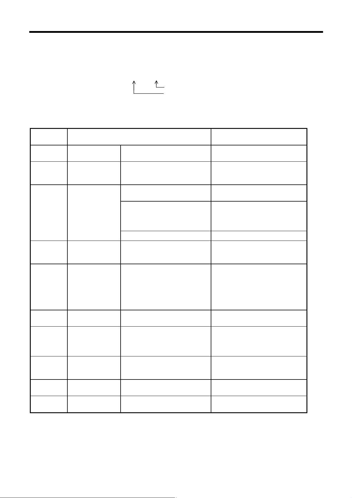
1.9 AUXILIARY AXIS ALARMS
A
1.9 AUXILIARY AXIS ALARMS
Display example
1. LIST OF ALARMS
S01 AUX SERVO ALM
(1) S01 AUX SERVO ALM
Alarm
information
Details Remedy
0011 PCB error 1 An error occurred in the
amplifier's internal PCB.
0013 Software
processing
timeout, clock error
0016
Motor type,
An error occurred in the
amplifier's internal reference
clock.
Motor type error • Use a correct amplifier and motor
detector type error
Detector initial communication
error.
Detector CPU error • Replace the motor (detector).
0017 PCB error
(A/D conversion
An error occurred in the
amplifier's internal A/D converter.
initial error)
0025
Absolute position
lost
An error occurred in the
detector's internal absolute
position data.
0034 CRC error An error occurred in the
communication with the NC.
0036 Communication
timeout, NC down
Communication with the NC was
cut off.
Axis No. 1 to 4
larm information
(Follows MR-J2-CT alarm information)
• Replace servo amplifier.
• Replace servo amplifier.
combination.
• Connect correctly.
• Replace the motor.
• Replace or repair cable.
• Replace servo amplifier.
• Turn the power ON for 2 to 3
minutes while the alarm is
occurring, and then turn the
power ON again.
• Replace the battery, and initialize
the absolute position again.
• Take countermeasures against
noise.
• Connect correctly.
• Turn the NC power ON.
• Replace the amplifier or NC.
0037 Parameter error
(Regenerative
The parameter setting value is
incorrect.
• Set the parameter correctly.
resistance error)
0038 Frame error An error occurred in the
communication with the NC.
0039 INFO error Undefined data was transferred
from the NC.
• Take countermeasures against
noise.
• Change the NC software version
to a compatible version.
I - 41
Page 58

(2) S02 AUX SERVO ALM
1. LIST OF ALARMS
1.9 AUXILIARY AXIS ALARMS
Alarm
information
0011 PCB error 1
(drive circuit error)
0013 Software
processing
timeout, clock error
Details Remedy
An error occurred in the
amplifier's internal PCB.
An error occurred in the
amplifier's internal reference
clock.
0015 EEROM error A write error occurred to the
EEROM in the amplifier.
0017 PCB error
(A/D conversion
An error occurred in the
amplifier's internal A/D converter.
error)
0018 PCB error
(LSI error)
An error occurred in the
amplifier's internal LSI.
0020 Detector error An error occurred in the
communication between the
servo amplifier and detector.
0024 Ground fault
detection
A ground fault of the output was
detected when the power was
turned ON.
(3) S03 AUX SERVO ALM
• Replace servo amplifier.
• Replace servo amplifier.
• Replace servo amplifier.
• Replace servo amplifier.
• Replace servo amplifier.
• Connect correctly.
• Replace or repair cable.
• Repair the ground fault section.
• Replace the cable or motor.
Alarm
information
Details Remedy
0010 Undervoltage The power voltage is 160V or
less.
0030 Regeneration error
The tolerable regeneration power
of the internal regenerative
resistor or external regenerative
option was exceeded.
Regenerative transistor error • Replace the servo amplifier.
0031 Overspeed The motor's rotation speed
exceeded the tolerable
momentary speed.
0032 Overcurrent A current exceeding the servo
amplifier's tolerable current
flowed.
• Review the power supply.
• Replace the servo amplifier.
• Set the parameter #002 correctly.
• Connect correctly.
• Lower the positioning frequency.
• Change the regenerative option
to a larger capacity.
• Lower the load.
• Review the power supply.
• Increase the acceleration/
deceleration time constant.
• Review the gear ratio.
• Replace the detector.
• Repair the wiring.
• Replace the servo amplifier.
• Take countermeasures against
noise.
I - 42
Page 59

1. LIST OF ALARMS
1.9 AUXILIARY AXIS ALARMS
Alarm
information
Details Remedy
0033 Overvoltage The voltage of the converter in
the servo amplifier was 400V or
more.
0046 Motor overheating An operation state causing the
motor to overheat continued.
0050 Overload 1 The servo amplifier or
servomotor overload protection
function activated.
0051 Overload 2 The max. output current flowed
for several seconds due to a
machine collision or overload.
0052 Excessive error A position deflection exceeding
the excessive error detection
setting value occurred.
• Wire correctly.
• Replace the servo amplifier.
• For the internal regenerative
resistor, replace the amplifier.
• For the external regenerative
option, replace the regenerative
option.
• Reduce the motor load.
• Review the operation pattern.
• Reduce the motor load.
• Review the operation pattern.
• Change to a motor or amplifier
with large output.
• Change the setting of the
automatic tuning response
characteristics.
• Correct the connection.
• Replace the servomotor.
• Review the operation pattern.
• Change the setting of the
automatic tuning response
characteristics.
• Correct the connection.
• Replace the servomotor.
• Increase the acceleration/
deceleration time constant.
• Increase the torque limit value.
• Review the power facility
capacity.
• Review the operation pattern.
• Replace the servomotor.
• Connect correctly.
• Repair or replace the cable.
I - 43
Page 60

(4) S52 AUX SERVO WRN
1. LIST OF ALARMS
1.9 AUXILIARY AXIS ALARMS
Alarm
information
0092 Battery voltage
drop
00E0 Over-regeneration
warning
Details Remedy
The absolute position detection
battery voltage dropped.
The regeneration power may
have exceeded the tolerable
range of the built-in regenerative
resistor or external regenerative
option.
00E1 Overload warning The overload alarm 1 could
occur.
00E3 Absolute position
counter warning
00E9 Main circuit OFF
warning
There is an error in the absolute
position detector internal data.
The servo ON signal was input
while the main circuit power was
OFF.
The contactor operation is faulty.
(5) Z70 AUX POS. ERR
• Mount a battery.
• Replace the battery and initialize
the absolute position.
• Lower the positioning frequency.
• Change the regenerative option
to a larger one.
• Lower the load.
• Refer to the items for S03 0050.
• Take countermeasures against
noise.
• Replace the servomotor.
• Turn ON the main circuit power.
Alarm
information
Details Cause Remedy
0001 Zero point
initialization
incomplete
0002 Absolute position
data lost
0003 Absolute position
system related
parameter error
(6) Z71 AUX DETEC. ERR
Alarm
information
Details Cause Remedy
0001 Absolute position
memory battery
voltage drop
The zero point (reference point)
has not been initialized in the
absolute position system.
The absolute position coordinate
data in the amplifier has been
lost.
The absolute position system
related parameters have been
changed or lost.
The data in the detector has been
lost.
Battery voltage drop.
Detector cable wire breakage or
looseness.
• Initialize the zero point (reference
point).
• Initialize the zero point (reference
point).
• Correctly set the parameters and
then initialize the zero point
(reference point).
• Check the battery and detector
cable and then initialize the zero
point (reference point).
I - 44
Page 61

(7) Z73 AUX SYSTEM WRN
1. LIST OF ALARMS
1.9 AUXILIARY AXIS ALARMS
Alarm
information
Details Cause Remedy
0001 Absolute position
memory battery
voltage warning
0003 Absolute position
counter warning
(8) M00 AUX OPER. ALM
Alarm
information
Details Cause Remedy
0001 Near-point dog
length insufficient
0003 Reference point
return direction
illegal
Battery voltage drop.
Detector cable wire breakage or
looseness.
An error occurred in the
detector's absolute position
counter.
When executing dog-type
reference point, the zero point
return speed is too fast or the dog
length is too short.
When executing reference point
return, the axis was moved in the
opposite of the designated
direction.
• Check the battery and detector
cable. The zero point does not
need to be initialized.
• Replace the detector.
• Lower the zero point return speed
or increase the dog length.
• Move the axis in the correct
direction.
0004 External interlock The axis interlock function is
• Cancel the interlock signal
valid.
0005 Internal interlock An interlock was established by
• Cancel the servo OFF.
the servo OFF function.
0007 Soft limit The soft limit was reached. • Check the soft limit setting and
machine position
0024 In absolute
position alarm.
Reference point
Reference point return was
executed during an absolute
position alarm.
• Initialize the absolute position
reference point and then fix the
absolute position coordinates.
return not possible.
0025 In initializing
absolute position.
Reference point
Reference point return was
executed while initializing the
absolute position.
• Initialize the absolute position
reference point and then fix the
absolute position coordinates.
return not possible.
I - 45
Page 62

(9) M01 AUX OPER. ALM
1. LIST OF ALARMS
1.9 AUXILIARY AXIS ALARMS
Alarm
information
Details Cause Remedy
0001 No operation mode The operation mode is not
designated, or the operation
mode was changed during axis
movement.
0003 Feedrate 0 The operation parameter's
feedrate setting is zero.
The operation parameter
feedrate setting is zero.
Or, the override is valid, and the
override value is zero.
0060 Station No.
designation illegal.
Starting not
A station No. exceeding the No.
of indexed divisions was
designated.
possible.
0061 Reference point
return incomplete.
Starting not
possible.
Automatic/manual operation was
started before reference point
return was executed with the
incremental system.
• Correctly designate the operation
mode.
• Set a value other than zero in the
feedrate setting or override value.
• Correctly designate the station
No.
• Execute the reference point
return.
0062 In initializing
reference point.
Starting not
possible.
0063 In absolute
position alarm.
Starting not
possible.
0064 In random
positioning mode.
Manual operation
not possible.
0065 Uneven indexing
station No. illegal.
Starting not
possible.
The start signal was input while
initializing the absolute position
reference point.
The start signal was input during
an absolute position alarm.
The manual operation mode was
started during the random
positioning mode.
The commanded station No. was
higher than 8 during uneven
indexing.
• Complete the absolute position
reference point initialization.
• Initialize the absolute position
reference point and then fix the
absolute position coordinates.
• Turn the random positioning
mode OFF before switching to
the manual operation mode.
• Check the commanded station
No.
I - 46
Page 63

AUXILIARY AXIS MCP ALARMS
1. LIST OF ALARMS
1.9 AUXILIARY AXIS ALARMS
Y02 AUX SYSTEM ALM
An error occurred in the data transmitted between the MCP and
auxiliary axis amplifier after the power was turned ON.
Error No. Details Remedy
0050
Background error The software or hardware may be
damaged.
Contact the service center.
0051
0000 CRC error
(10 times/910.2ms)
0001
CRC error
(2 continuous times)
0002 Reception timing error
(2 continuous times)
××03
Data ID error
(2 continuous times)
××: Axis No.
××04
No. of reception frames error
(2 continuous times)
××: Axis No.
A communication error has occurred
between the controller and amplifier.
• Take measures against noise.
• Check that the communication cable
connector between the controller and
amplifier and one between the amplifiers
are tight.
• Check whether the communication cable
between the controller and amplifier and
one between the amplifiers are
disconnected.
• A driving amplifier may be faulty. Take a
note of the 7-segment LED contents of
each driving amplifier and report to the
Service Center.
Y03 AUX AMP UNEQU.
The amplifier is not correctly
connected.
Check the auxiliary axis amplifier mounting state.
• Check the end of the cable wiring.
• Check the cable for broken wires.
• Check the connector insertion.
The auxiliary axis amplifier input power is not being input.
The auxiliary axis amplifier axis No. switch is illegal.
Error No. Details
Axis No.1 to 4
bit correspondence (bit 0 : 1st axis, bit 1: 2
nd
axis, bit 2: 3rd axis, bit 3: 4th axis)
I - 47
Page 64

1.10 COMPUTER LINK ERRORS
A
1.10 COMPUTER LINK ERRORS
Error Message
L01
DNC ERROR
Error
No.
–4
–10 HOST ER (CNC DR) signal is not turned
–15 Communication ends with parity H. 1) Recheck the HOST software as to
–16 Communication ends with parity V. 1) Recheck the data to be transmitted to
–17
Communication ends with timeout.
CNC has a 248-byte receive buffer.
The time during which CNC receives
248 bytes exceeds the “TIME-OUT”
value set in the I/O device parameter.
ON.
lthough CNC transmits DC3 (request to
stop data transfer) to the HOST, it
receives data of 10 bytes or more from
the HOST, thus terminates
communication.
When CNC is transmitting data to the
HOST, it receives data of 10 bytes or
more from the HOST.
1. LIST OF ALARMS
Details Remedy
1) Set a greater timeout value in the
input/output device parameter.
2) Recheck the HOST software as to
whether or not the HOST transmits
data in response to DC1 from CNC
(data request).
3) Check whether or not start code of
computer link parameter is set to 0.
1) Check whether or not the cable is
disconnected from the connector.
2) Check whether or not the cable is
broken.
3) Check whether or not the HOST power
is turned ON.
whether or not the data to be
transmitted to CNC is ISO code.
CNC.
1) Recheck the software as to whether or
not the HOST stops transmitting data
within 10 bytes after receiving DC3.
2) Recheck the HOST software as to
whether or not the HOST transmits
data such as a command or header to
CNC during receiving a work program.
I - 48
Page 65

1.11 USER PLC ALARMS
Message
U01
No PLC
U10
Illegal PLC
U50
Stop PLC
Sub-status
1 2
– – The ladder is not a GPPW ladder or
0x0010 – Scan time error
0x0040 – Ladder operation mode illegal
0x0080 – GPPW ladder code error
0x008x – PLC4B ladder code error
0x0400 Number of
ladder steps
0x800x Number of
ladder steps
The ladder is stopped. Start the ladder.
1. LIST OF ALARMS
1.11 USER PLC ALARMS
Details Remedy
PLC4B ladder.
(Note) Emergency stop (EMG) will
be applied.
The scan time is 1 second or longer.
A ladder different from the
designated mode was downloaded.
(Note) Emergency stop (EMG) will
be applied.
(Note) Emergency stop (EMG) will
be applied.
An illegal circuit was found in the
PLC4B ladder.
bit1: PC medium-speed circuit
illegal
bit2: PC high-speed circuit illegal
(Note) Emergency stop (EMG) will
be applied.
Software illegal interrupt
The ladder process stopped
abnormally due to an illegal software
command code.
(Note) Emergency stop (EMG) will
be applied.
Software exceptional interrupt
The ladder process stopped
abnormally due to a bus error, etc.
bit 0: BIN command operation error
bit 1: BCD command operation error
bit6: CALL/CALLS/RET
command error
bit7: IRET command execution error
(Note) Emergency stop (EMG) is
applied for bit 6/7.
Download the ladder of the
format selected with the
PLC environment selection
parameters (bit selection
#51/bit 4).
Edit the ladder size to a
smaller size.
Download the ladder
having the same format as
when the power was reset
or turned ON.
Download the correct
GPPW format ladder.
Download the correct
PLC4B format ladder.
Turn the power ON again.
If the error is not reset,
download the correct
ladder.
Refer to the methods for
using the BCD and BIN
function commands.
Turn the power ON again.
If the error is not reset,
download the correct
ladder.
(Note) The number of ladder steps displayed on the screen may not match the actual number of error
occurrence steps because of the ladder timing. Use this as a guideline of the occurrence place.
I - 49
Page 66

2. OPERATION MESSAGES ON SETTING AND DISPLAY UNIT
2.1 OPERATION ERRORS
2. OPERATION MESSAGES ON SETTING AND DISPLAY UNIT
If a setting operation error occurs on any setting and display unit screen‚ the error No. EOO and a message
describing the details of the error will display in the line above the data setting area or the menu display
area.
2.1 OPERATION ERRORS
∆: Message requiring resetting and restarting
×: Message requiring restarting after canceling error conditions
(The bold characters are the messages displayed on the screen.)
Error No. Error message Details
E01 SETTING ERROR
∆
(Word editing)
• W hen the incremental detection system was used, the parameter
• The data input for the standard parameter setting or during
• A value from 4 to 10 was specified for #1043 lang.
• W hen the machine manufacturer macro program memory area is
• The setting data is incorrect. An alphabetic character was set
when only number can be set‚ etc.
• Data was input without setting number (#).
• Even though no retrieval data was set, menu key [ ↓ ] or [ ↑ ] was
pressed.
• Even though no data is stored in edit buffers, menu key “Replace”
was pressed.
• One of the following characters was entered as the first character
of the retrieval data and edit buffers: 0 to 9, “. ”, “ ” (space), “+”,
“−”, “=”, “*”, “[ ] ”, and “ " " ”.
(#0 absolute position setting) was set on the absolute position
setting screen.
execution of formatting is not “Y” or “N”.
• Even though no language data exists, its output and comparison
were attempted. Check the numbers (0253 and 0254) of the
language data to be output.
the SRAM area, the setup parameter #1060 SETUP was set to
“20”.
• When the machine manufacturer macro program memory area is
the SRAM area, writing of the machine manufacturer macro
program was attempted on PROGRAM COPY screen.
I - 50
Page 67

2. OPERATION MESSAGES ON SETTING AND DISPLAY UNIT
2.1 OPERATION ERRORS
Error No. Error message Details
E02 DATA OVER
• The compensation data specification exceeded the range when
• When workpiece coordinate offsets are measured, the
• When there was no option, 2 or more was specified for #1043
E03 No. NOT FOUND
E04 DEV. NOT READY
• The setting data exceeded the setting range.
∆
inputting the tool offset data on tape‚ so that block could not be
input. Press the INPUT key again while the input screen is
displayed‚ and the input will continue from the next block.
calculation results given by pressing the CALC key are exceeding
the specified range. Correctly specify the tool length or the wear
data of cutting edges used for the calculation.
lang. Otherwise, an option was added and 23 or more was
specified for #1043 lang.
• The corresponding setting No. (#) was not found. This error
∆
occurs if a setting No. not found on the screen was set and input‚
or if a variable No. not found in the specifications was set and
input for the common variables.
• When the tool length was measured manually, a nonexisting tool
wear compensation number was specified and the sensor was
turned ON. Specify the R register of the offset number correctly.
• The input/output unit power is not ON.
×
• The cable is disconnected.
• Setting of the transfer speed (baud rate) does not agree.
I - 51
Page 68

2. OPERATION MESSAGES ON SETTING AND DISPLAY UNIT
2.1 OPERATION ERRORS
Error No. Error message Details
E05 NOT
ACCEPTABLE
E06 NO SPEC
• The PLC timer cannot be set from the screen when the program
×
is valid. (When machine parameter bit selection #6449 bit 1 is set
to 1.)
• The PLC counter cannot be set from the screen when the
program is valid. (When machine parameter bit selection #6449
bit 0 is set to 1.)
• The tool registration data setting is prohibited. (When special
relay E71 is valid by the PLC.)
• Setting from the tool life management screen is prohibited.
• Absolute position setting screen’s #1 “ORIGIN” and #2 “ZERO”
cannot be set when #0 “INIT SET” is invalid.
• The total of axes set in #1001 SYS_ON‚ #1002 axisno is illegal.
Set so that the total No. of axes is within the specifications range
for the target model.
• #1037 cmdtyp is not within the setting range.
• The INPUT key was pressed to perform search for the program
that is in background edit status on the word edit screen.
• The menu keys (Replace and Insert) on the word edit screen
were manipulated when a running program is displayed (PDISP
signal: ON).
• An attempt was made to set MDI data in an MDI setting lock state
(the MDI setting lock parameter is specified with 0 and a non-MDI
mode is valid).
• Language data in display selection status was entered. Change
the display selection status once before entering the data.
(#1043 lang)
• When the manual value command protection (#1228 aux12/bit7)
function is valid, the first monitor screen was manipulated by
manual command operation (M, S, and T keys).
• The menu key for a function not in the specifications was
×
pressed.
• A parameter not in the specifications was set.
• A language that was not added as an option was selected.
(#1043 lang)
• Set up parameter #1049 mmac_R was set to “1” when the
machine manufacturer macro option was not valid.
• Set up parameter #1060 SETUP was set to “20” when the
machine manufacturer macro option was not valid.
• Writing of the machine manufacturer macro program with the
PROGRAM COPY screen was attempted when the machine
manufacturer macro option was not valid.
I - 52
Page 69

2. OPERATION MESSAGES ON SETTING AND DISPLAY UNIT
2.1 OPERATION ERRORS
Error No. Error message Details
E07 RESET END
E08 PHYSICAL ERR
E09 TIME OUT
E10 MEMORY OVER
E11 PROG. No. DUPLI
E12 FILE ENTRY
OVER
E13 NB NOT FOUND
E14 PROG. NOT
FOUND
E15 EDIT LOCK B
E16 EDIT LOCK C
E17 PARITY H ERR
E18 PARITY V ERR
• The input/output operations were forcibly stopped by reset‚ etc.
∆
(including EMG).
• The input/output parameter setting or input/output unit side
×
setting was incorrect.
• The input/output unit parameter “#9116 TIME-OUT SET” setting
×
was too short.
• There is no EOB code in the machining program.
• The program cannot be written because the memory capacity is
×
exceeded.
• This error occurs when the MDI data setting on the MDI screen
exceeds 500 characters‚ or when saving MDl‚ editing or making a
program on the edit screen‚ input on the data input/output screen‚
program copy‚ etc.
• When registering a machining program in the memory‚ a program
∆
with the same No. as the designated program No. was found in
the memory. Refer to the program file to find a program No. not
being used‚ and reset the program No.
• A program with the same No. as the machining program to be
copied from the memory was found in the IC card.
• This error occurs during MDI registration in the MDI screen or
during creation of a program in the edit screen.
• When registering a machining program in the memory‚ the No. of
×
programs determined in the specifications is exceeded‚
preventing registration.
This error occurs during MDI registration in the MDI screen‚
creation of a program in the edit screen‚ data input in the data
input/output screen‚ and program copy.
• The block with the designated sequence No. or block No. does
∆
not exist in the designated program.
• The designated program is not found in the memory.
∆
• The corresponding program No. was not found with search of
tape memory during graphic check.
• An operation (edit‚ input/output‚ buffer correction‚ etc.) inhibited
×
for machining program B was attempted.
• An operation (edit‚ input/output‚ buffer correction‚ etc.) inhibited
×
for machining program C was attempted.
• A parity H error was detected during data input‚ etc.
×
• Check the paper tape or input device. This error may occur if the
paper tape is dirtied with oil‚ etc.
• A parity V error was detected during data input.
×
• Check the paper tape to see whether the number of characters in
the significant information section of a block is odd.
• Also check the state (cable wiring‚ noise measures‚ etc.) of the
connected equipment.
I - 53
Page 70

2. OPERATION MESSAGES ON SETTING AND DISPLAY UNIT
2.1 OPERATION ERRORS
Error No. Error message Details
E20 OVER RUN ERR
E21 PROGRAM
RUNNING
E22 CODE CHANGE
ERR
E24 PLC RUN
E25 DATA MEMORY
ERR
E26 NO
CHARACTERS
E35 COMPARE
ERROR
E40 OP MODE ERROR
×
×
×
×
×
∆
×
×
• The control method using the DC codes‚ etc.‚ for the input/output
operation is incorrect.
• Check the settings of the input/output unit parameters‚ and the
settings on the input/output unit side‚ and reset if necessary.
• Deletion of a machining program was attempted during
operation.
• Search was attempted during operation.
• Change of data such as parameters was attempted during
operation.
• Start of graphic check was attempted during operation.
• When using the two systems, the program being buffer corrected
was running with the other system.
• Erasing or inputting (IC → NC) of a program in the IC card being
used was attempted.
• Formatting of the IC card was attempted during automatic start.
• Accessing to the host computer was attempted during automatic
operation.
• There was an illegal code on the paper tape.
• Data input/output or comparison was attempted when the PLC
was not stopped.
• Analog output adjustment was attempted when the PLC was not
stopped.
• An attempt was made to input or output language data during
PLC execution.
• When the machine manufacturer macro program memory area
was set to the FROM area, formatting of the FROM area (#1060
SETUP “20”) was attempted when the PLC was not stopped,
writing of the machine manufacturer macro program was
attempted on the PROGRAM COPY screen, or input of the macro
program was attempted.
(Measures)
Stop the PLC.
• Set the control unit rotary switch to 1.
• Set the onboard file screen RUN/STOP setting to 1.
• When inputting the tool offset data onto tape‚ an offset type
exceeding the specifications range was designated‚ and that
block could not be input. If the INPUT key is pressed again in the
input screen‚ the input will continue from the next block.
• The designated character string was not found from the block
displayed on the screen to the end of the program when
searching with data search in the edit screen. Press the INPUT
key again’ and the search will start at the head of the program.
• An inconsistency was found in the paper tape and memory data
during comparison.
• Continuous or step graphic check was not possible because the
operation mode was illegal.
I - 54
Page 71

2. OPERATION MESSAGES ON SETTING AND DISPLAY UNIT
2.1 OPERATION ERRORS
Error No. Error message Details
E50
E51
E52
E53
E54
E55
E56
E60
E60 IOP ERROR – 20 (framing and H/W errors)
FILE ERR
FILE OPEN ERR
FILE CLOSE ERR
FILE SEEK ERR
FILE READ ERR
FILE DELETE
ERR
FILE INSERT ERR
IOP ERR
• If one of these errors occurs‚ the editing or input/output
×
operations cannot be continued. Contact the Service Center.
As for E50‚ a classification No. will display at the end of the
message. Inform the service center of this No. as well.
A classification number is displayed after the message for E60.
×
Refer to the section shown in parentheses‚ and remedy the
problem.
E60 lOP ERROR – 2 (Port already being used)
E60 lOP ERROR – 4 (E09 TIME OUT)
E60 lOP ERROR – 5 (E08 PHYSICAL ERR)
E60 lOP ERROR – 7 (E07 RESET END)
E60 lOP ERROR – 10 (E04 DEV. NOT READY)
E60 lOP ERROR – 15 (E17 PARITY H ERR)
E60 lOP ERROR – 16 (E18 PARITY V ERR)
E60 lOP ERROR – 17 (E20 OVER RUN ERR)
E60 lOP ERROR – 18 (E22 CODE CHANGE ERR)
• Setting for the bit length is incorrect. (Baud rate, stop bit, and
character length)
Check the setting of the I/O device system and its parameters
and set it again.
• Check the situations of the connected devices (cable wiring and
noise measures).
• Data was input/output or the tape search was executed during the
host link.
Set 0 in #8109 HOST LINK, and then set 1 again before
performing the cycle start. (IOP error -2)
• The host link parameter was turned ON during connecting to the
Anshin-net. Turn the Anshin-net valid OFF. (IOP error -2)
• When #10812 Anshin-net/ Machine builders network system
valid is set to 1, the modem connection port of the Anshin-net or
machine builders network system is occupied.
Perform inputting or outputting using a port other than the modem
connection port. (IOP error -2)
• When connecting the GX Developer (when the bit selection
parameter #6451 bit5 is set to 1), the port 2 of the RS232C
communication port is always used.
Use a port other than the port 2 of the RS232C communication
port. (IOP error -2)
I - 55
Page 72

2. OPERATION MESSAGES ON SETTING AND DISPLAY UNIT
2.1 OPERATION ERRORS
Error No. Error message Details
E62 I/O PARAM ERR
E64 PROGRAM No.
ERR
E65 PROG. No. DUPLl
E66 NO PROG.
NUMBER
E69 PROG. CHECK
MODE
E70 TOOL No. DUPLl
E71 TOOL ENTRY
OVER
E73 CAN’T
CALCULATE
E74 MENU
IMPOSSIBLE
• The “EIA code” data set for I/O parameter is of an unusable code.
∆
• The unusable codes are those used as the EIA standard codes
and the even hole codes.
• The same No. as the program No. designated for program copy
∆
was found in the memory.
• During tape input‚ the first character of the machining program
block is the program No. address “O” or “L”.
• During tape input‚ the same No. as the specified program was
∆
found in the memory.
• During tape input‚ the program No. was not found on the paper
∆
tape‚ and a program No. was not designated on the screen’s data
setting area. Set the program No.‚ and input again.
• Search (operation search) was attempted during program check
×
(continuous or step).
• Retry search after the program check is completed‚ or after
resetting the program search
• A tool No. already registered was newly registered on the tool life
∆
management screen.
• Registration of data exceeding the max. No. of registerable tools
×
was attempted on the tool life management screen.
• When inputting the tool offset data onto tape‚ a compensation
number exceeding the specifications range was specified‚ and
that block could not be input. If the INPUT key is pressed again in
the input screen’ the input will continue from the next block.
• The coordinate value of the hole center cannot be obtained.
×
• Reset the measurement point, which must not applied to the
following conditions.
The measurement A point is the same as the Y coordinate of
the C point.
The measurement B is the same as the Y coordinate of the C
point.
The slope of the line through A and C point is the same as the
slope of the line through B and C point.
• Press the operation menu “= Input” or “+ input” during the tool
×
measurement.
• Press the operation menu “= Input” or “+ input” during the manual
value command mode.
• Press the screen selection menu on which “↓” is displayed during
the tool measurement.
• Press the screen selection menu on which “↓” is displayed during
the manual value command mode.
I - 56
Page 73

2. OPERATION MESSAGES ON SETTING AND DISPLAY UNIT
2.1 OPERATION ERRORS
Error No. Error message Details
E75 TLM ILL. SIGNAL
E76 TOOL No. ERROR
E77 AXIS No.
REF-RET
E78 AX UNMATCH
(TLM)
E79 NO REF-RTN
(TLM)
E80 TOP SEARCH
ERR
E82 ALREADY
RESEARCH
E84 CAN’T IN/OUT
• The sensor signal was already ON when the tool measurement
mode (TLM) signal was validated.
• After the tool measurement mode (TLM) signal was validated, the
sensor signal turned ON when there was no axis movement.
• The sensor signal turned ON at a position within 100µm from the
final entry start position.
• Turn the tool measurement mode signal input OFF, or turn the
sensor signal OFF and move the axis in a safe direction.
Note) This display will be erased when another screen is opened.
The display will not be erased even if the tool measurement
mode signal input is turned OFF, or if the axis is moved in a
direction away from the sensor.
• The offset No. to be used for workpiece coordinate system offset
×
data measurement was invalid. Restart from tool selection.
(Correctly specify the R register that contains the offset number.)
• Zero point return has not been completed for the axis being
×
measured. Return the axis to the zero point.
• During movement of two or more axes‚ the sensor turned ON and
×
the tool length was measured.
Keep off from the sensor and perform the measurement for one
axis at a time.
• The sensor turned on for an axis that has not completed dog-type
×
reference point return‚ and the tool length was measured. Return
the axis to the zero point.
• The program head search (unmodal type search) was not
×
executed before type 2 (standard specification) restart search
was executed for program restart. Set the type to unmodal,
search for the head of the program, and then search for the
restart block with type 2.
• After completing the type 1 or type 2 search for program restart,
×
the unmodal type, type 1 or type 2 search was attempted again.
If program restart is continued (if the axis is return to the restart
position with automatic or manual operations), the program will
restart from the block searched for first.
To search again, cancel the previous search by resetting, and
then search again.
• An attempt was made to input a parameter in the setup
×
parameter locked state. Refer to the manual issued by the
machine manufacturer.
• The parameter “#1925 EtherNet” of the high-speed program
server function is set to 0.
• When writing data to the IC card, the file name is illegal.
(Exceeding 8 characters of file name + 3 characters of
extension.)
I - 57
Page 74

2. OPERATION MESSAGES ON SETTING AND DISPLAY UNIT
2.1 OPERATION ERRORS
Error No. Error message Details
E86 INPUT DATA ERR
E87 NOT EDIT PROG.
E88 CAN’T ADD
BLOCK
E91 MODE ERROR
(PBK)
E98 CAN’T
RESEARCH
E165 AUX RUNNING
E190 FORE EDITING
E191 NOT COM.
SEARCH
E200 ADJUST ERROR
• When inputting the tool offset data‚ the data format was not
×
correct‚ so that block could not be input.
• If the INPUT key is pressed again in the input screen‚ the input
will continue from the next block.
• When data is read from parameter tape, its format is incorrect.
• The format of file written to the NC memory is illegal.
• Playback edit was executed for a fixed cycle subprogram.
×
Playback edit of a fixed cycle subprogram is not possible.
• Playback edit cannot be executed unless the block being edited
×
with playback is displayed to the end (EOB) on the left side of the
machining program display area. Press the cursor key
display the whole block to the end. Then‚ input the data.
• G90 was set when “PB_G90” was OFF.
×
• G91 was set when “PB_G90” was ON.
• When restarting the program, the type 3 restart search was
×
attempted with a program containing no T command. Check the
program.
• When restarting the program, the T command corresponding to
the type 3 restart search was not found in the program. Check the
program.
• When restarting a program for 2-systems, restart search was
performed simultaneously for the 1st and 2nd systems, and then
the 2nd system was searched again.
If program restart is continued (if the axis is return to the restart
position with automatic or manual operations), the program will
restart from the block searched for first.
To search again, cancel the previous search by resetting, and
then search again.
• When carrying our program restart, type 3 restart search was
attempted while the machine was at the negative (–) side of the
restart limit parameters. Manually move the machine to the
positive (+) side of the restart limit parameters, and search again.
• The keys other than Function/Menu/Previous page/Next page
×
were pressed in Auxiliary monitor screen during auxiliary axis
operation.
• An attempt was made to perform background search for the
×
program that is in foreground search status. (Word editing)
• Operation search was attempted in tape mode.
×
• The hardware status can’t be read correctly‚ so automatic
×
adjustment was not possible.
• Check the remote l/O unit.
• A Z55 RIO NOT CONNECT occurred.
• Adjust manually.
• Unit defect (replace unit)
↓
‚ and
I - 58
Page 75

2. OPERATION MESSAGES ON SETTING AND DISPLAY UNIT
2.1 OPERATION ERRORS
Error No. Error message Details
E201 UNIT NOT EQUIP
E301 CONNECT
ERROR
E302 LOGIN ERR
E303 TIME OUT
E311 DOWNLOAD ERR
E312 UPLOAD ERR
E313 NO FILE
E314 FILE DUPLICATE
E315 FILE WRITE ERR
E316 FILE READ ERR
E317 MEMORY OVER
E318 OVER FLOW ERR
E319 DIRECTORY ERR
E320 HR437
UNEQU
• The analog output unit is not mounted.
×
• Confirm the remote l/O unit.
• Prepare a unit having analog output.
• Check the connection (power and signal wires)
• Unit defect (replace unit)
• A socket connection attempt failed during Ethernet
×
communication.
• Check the host address, the setting of the port No. and that the
host computer is turned ON.
• A login attempt failed during Ethernet communication. Check the
×
user name and password.
• Check the account settings, such as the home directory.
• Transmission of a file with Ethernet communication ended
×
because of timeout.
• An attempt to read a host file failed during Ethernet
×
communication.
• An attempt to write to a host file failed during Ethernet
×
communication.
× • The file specified by host receive (host → IC) operation during
Ethernet communication is not found in the host.
• The file specified by host send (IC → host) operation during
Ethernet communication is not found in the IC card.
× • The file name specified to be stored by host receive (host → IC)
operation during Ethernet communication already exists in the IC
card.
• The file name specified to be loaded by host send (IC → host)
operation during Ethernet communication already exists in the
host.
• An attempt to write to the IC card failed during Ethernet
×
communication.
• An attempt to read a file from the IC card failed during Ethernet
×
communication.
• IC card memory is full.
×
• NC memory is full.
• A host directory contains too many files.
×
• An attempt to move a directory failed.
×
• In the IC card device, accessing a directory in the nineteenth layer
or more was attempted.
• When backup or writing of the expansion cassette into/from the
×
FROM, the expansion cassette (HR437) was not mounted in
CBUS#1 or was incorrectly mounted.
• When backup or writing of the expansion cassette into/from the
FROM, a card other than the expansion cassette (HR437) was
mounted in CBUS#1.
• When the program memory was formatted to 1280m or more, the
expansion cassette (HR437) was not mounted in CBUS#1.
I - 59
Page 76

2. OPERATION MESSAGES ON SETTING AND DISPLAY UNIT
2.2 OPERATION MESSAGES
2.2 OPERATOR MESSAGES
The following messages indicate the status of the setting and display functions‚ and are not operation
errors. They are mainly used to show that operation is normal‚ and serve as guides for the following
operations. There is no classification by numbers.
2.2.1 SEARCH AND OPERATION RELATED
Message Message details
SEARCH EXECUTION
SEARCH COMPLET
BUFFER EDIT
CAN’T BUF. EDIT
DATA PROTECTING
• Search is being executed normally.
• Search was completed normally.
The buffer is being corrected. This
appears when the cursor or a tab key is
pressed and the buffer correction mode
is entered. This is erased when INPUT is
pressed.
When using 2 systems, the program
being buffer corrected is being used by
the other system.
Buffer correcting of a machine
manufacturer macro program was
attempted.
Buffer correcting is prohibited since the
data protection key 3 is valid.
I - 60
Page 77

2. OPERATION MESSAGES ON SETTING AND DISPLAY UNIT
2.2.2 MDI/EDITING RELATED
Message Message details
2.2 OPERATION MESSAGES
MDI NO SETTING
MDI SETTING COMPLETE
MDI ENTRY COMPLETE
MDI RUNNING
PUSH KEY SERCH/PROG
EDITING
PROGRAM RUNNING
DELETE? (Y/N)
BACK GROUND EDITING
• Only display of MDI data (no execution)
• The MDI data setting has been completed (execution is now possible).
• The MDI data was saved in the memory with the specified program
No.
• The NC is operating with an MDI program‚ and the MDI data cannot be
corrected.
• Status in which no programs to be edited have been called on the
editing screen. To edit‚ press the SEARCH or PROGRAM edit key.
• The details of a program are being edited on the screen. Press INPUT
to write the data in the memory.
• A machining program to be edited is currently being run with memory
operation‚ and cannot be edited.
• Waiting for a key entry (whether to delete the program) in word edit
status (when the background search menu is selected)
• Background edit mode
EDIT POSSIBLE
EDIT IMPOSSIBLE
WORD SEARCH FIN
• Editing can be performed in foreground edit mode.
• Editing cannot be performed in foreground edit mode.
• This state also occurs during feed hold or fixed cycle mode
(single-block stop).
• The word matching the search data was searched on word editing.
I - 61
Page 78

2. OPERATION MESSAGES ON SETTING AND DISPLAY UNIT
2.2 OPERATION MESSAGES
2.2.3 DATA INPUT/OUTPUT RELATED
Message Message details
DATA IN EXECUTION
DATA WRITING IN PROGRESS
DATA IN COMPLETE
COMPARE EXECUTION
COMPARE COMPLETE
DATA OUT EXECUTION
DATA OUT COMPLETE
ERASE EXECUTION
ERASE COMPLETE
COPY EXECUTION
COPY COMPLETE
• Data is being read without error from the paper tape.
• Data has been entered normally and the input data is being written to
the ROM.
• Data has been stored without error.
• Comparison is being executed without error.
• Comparison has completed without error.
• Data is being output without error.
• Data has been output without error.
• Data is being erased without error.
• Data has been erased without error.
• The machining program is being copied without error.
• The machining program has been copied without error.
CONDENSE EXECUTION
CONDENSE COMPLETE
MERGE EXECUTION
MERGE COMPLETE
No. CHANGE EXECUTION
No. CHANGE COMPLETE
• The machining program is being condensed without error.
• The machining program has been condensed without error.
• The machining program is being merged without error.
• The machining program has been merged without error.
• The machining program No. is being changed without error.
• The machining program No. has been changed without error.
I - 62
Page 79

2. OPERATION MESSAGES ON SETTING AND DISPLAY UNIT
2.2 OPERATION MESSAGES
2.2.4 S-ANALOG OUTPUT ADJUSTMENT RELATED
Message Message details
ADJUST EXECUTION
ADJUST COM PLETE
2.2.5 AUXILIARY AXIS
Message Message details
CONTINUE Y/N
BACKUP EXECUTION
BACKUP COMPLETE
AUX. WRITING EXEC.
WRITE COMPLETE
• Analog output adjustment is being executed without error.
• Analog output adjustment has completed without error.
• Type “Y” or “N” to specify whether to perform operation.
• The auxiliary axis parameters are being backed up in SRAM.
• The backup of the auxiliary axis parameters in SRAM has been
completed.
• The auxiliary axis parameters in SRAM is being written to MR-J2-CT.
• The writing of the auxiliary axis parameters in SRAM to MR-J2-CT has
been completed.
ABS POS RESTORED
2.2.6 PARAMETER BACKUP RELATED
Message Message details
BACKUP EXEC. Y/N
BACKUP EXECUTION
BACKUP COMPLTE
RESTORE EXEC. Y/N
RESTORE EXECUTION
RESTORE COMPLETE
• The absolute position in SRAM has been restored in MR-J2-CT.
Type “Y” or “N” to specify whether to perform the operation.
The parameters are being backed up.
Backup of the parameters has been completed.
Type “Y” or “N” to specify whether to perform the operation.
The parameters are being restored.
Restoration of the parameters has been completed.
I - 63
Page 80

2.2.7 OTHERS
Message Message details
2. OPERATION MESSAGES ON SETTING AND DISPLAY UNIT
2.2 OPERATION MESSAGES
DATA PROTECTING
BASE PARA. SET? (Y/N)
BASE PARA EXECUTION
EXECUTE FORMAT? (Y/N)
FORMAT EXECUTION
SETUP COMPLETE
NON SETUP
CONFIRM OPE? (Y/N)
INPUT? (Y/N)
• The data protection key is valid‚ and the various data cannot be set or
erased‚ etc.
• Waiting for the key input of standard parameter setting (Y/N).
• The standard parameters are being set.
• Waiting for the key input of execute format (Y/N).
• Formatting is being executed.
• The simple setup has been completed.
Setup with #1060 SETUP "1" has been completed.
Formatting with #1060 SETUP "20" has been completed.
• Completed without executing simple setup.
(When “N” has been set for both “BASE PARA. SET? (Y/N)” and
“EXECUTE FORMAT? (Y/N)”.)
• Confirmation for erasing operating time or alarm history.
• Waiting for the key input of tool length data by manual measurement.
V-ANALIZER EXEC.
ROM WRITE? (Y/N)
DATA WRITING
WRITE COMPLETE
• Waveform display data cannot be output while waveform is displayed.
• The system is waiting for a key input to indicate whether to write the
macro programs into the FROM.
• The macro program is being written into the FROM.
• The macro program has been written into the FROM.
I - 64
Page 81

3. PROGRAM ERROR
3. PROGRAM ERROR
(The bold characters are the message displayed in the screen.)
These alarms occur during automatic operation‚ and the causes of these alarms are mainly program errors
which occur‚ for instance‚ when mistakes have been made in the preparation of the machining programs or
when programs which conform to the specification have not been prepared.
Error No. Details Remedy
P 10 EXCS. AXIS No.
The number of axis addresses
commanded in the same block exceeds
the specifications.
P 11 AXIS ADR. ERROR
The axis address commanded by the
program and the axis address set by the
parameter do not match.
P 20 DIVISION ERROR
An axis command which cannot be
divided by the command unit has been
issued.
P 29 NOT ACCEPT CMND
The normal line control command
(G40.1, G41.1, G42.1) has been issued
during the modal in which the normal line
control is not acceptable.
P 30 PARITY H
The number of holes per character on the
paper tape is even for EIA code and odd
for ISO code.
P 31 PARITY V
The number of characters per block on
the paper tape is odd.
P 32 ADDRESS ERROR
An address not listed in the specifications
has been used.
P 33 FORMAT ERROR
The command format in the program is
not correct.
P 34
G-CODE ERROR
A G code not listed in the specifications
has been used.
G51.2 or G50.2 was commanded when
the rotary tool axis No. (#1501 polyax)
was set to “0”.
G51.2 or G50.2 was commanded when
the tool axis was set to the linear axis
(#1017 rot “0”).
• Divide the alarm block command into two.
• Check the specifications.
• Revise the axis names in the program.
• Check the program.
• Check the program.
• Check the paper tape.
• Check the tape puncher and tape reader.
• Make the number of characters per block on
the paper tape even.
• Set the parameter parity V selection OFF.
• Check and revise the program address.
• Check and correct the parameters values.
• Check the specifications.
• Check the program.
• Check and correct the G code address in the
program.
• Check the parameter setting values.
I - 65
Page 82

3. PROGRAM ERROR
Error No. Details Remedy
P 35 CMD-VALUE OVER
The setting range for the addresses has
been exceeded.
P 36 PROGRAM END ERR
“EOR” has been read during tape and
memory operation.
P 37 PROG. NO. ZERO
A zero has been specified for program
and sequence numbers.
P 39 NO SPEC ERR
• A non-specified G code was specified.
• The high-speed program server operation
specifications are not provided.
P 40 PREREAD BL. ERR
When tool radius compensation is
executed‚ there is an error in the pre-read
block and so the interference check is
disabled.
P 60 OVER CMP. LENG.
The commanded movement distance is
excessive. (Over 2
31
P 62 F-CMD. NOTHING
• No feed rate command has been issued.
• There is no F command in the cylindrical
interpolation or pole coordinate
interpolation immediately after the G95
mode is commanded.
P 65 NO G05P3 SPEC
P 70 ARC ERROR
• There is an error in the arc start and end
points as well as in the arc center.
• The difference of the involute curve
through the start point and the end point is
large.
• Check the program.
• Enter the M02 and M30 command at the end
of the program.
• Enter the M99 command at the end of the
subprogram.
• The program numbers are designated across
a range from 1 to 99999999.
• The sequence numbers are designated
across a range from 1 to 99999.
• Check the specifications.
• Reconsider the program.
• Reconsider the axis address command.
)
• The default movement modal command at
power ON is G01. This causes the machine
to move without a G01 command if a
movement command is issued in the
program, and an alarm results. Use an F
command to specify the feedrate.
• Specify F with a thread lead command.
• Check the high-speed mode III
specifications.
• Check the numerical values of the addresses
that specify the start and end points, arc
center as well as the radius in the program.
• Check the “+” and “–” directions of the
address numerical values.
I - 66
Page 83

3. PROGRAM ERROR
Error No. Details Remedy
P 71 ARC CENTER
• The arc center is not sought during
R-specified circular interpolation.
• The curvature center of the involute curve
cannot be obtained.
P 72 NO HELICAL SPEC
A helical command has been issued
though it is not included in the
specifications.
P 90 NO THREAD SPEC
A thread cutting command has been
issued though it is not included in the
specifications.
P 93 SCREW PITCH ERR
The screw pitch has not been set
correctly when the thread cutting
command is issued.
P100 NO CYLIND SPEC
Cylindrical interpolation was commanded
when the cylindrical interpolation
specifications were not provided.
P111 PLANE CHG (CR)
Plane selection commands (G17, G18,
and G19) were issued when a coordinate
rotation command (G68) was issued.
P112 PLANE CHG (CC)
• A plane selection command (G17‚ G18‚
G19) has been issued when the tool
radius compensation command (G41‚
G42) or nose R compensation
command (G41‚ G42‚ G46) is issued.
• The plane selection command was
issued when nose R compensation is
completed‚ there is no axial movement
command after the G40 command‚ and
the compensation has not been
canceled.
P113 ILLEGAL PLANE
The arc command axis is not on the
selected plane.
• Check the numerical values of the addresses
in the program.
• Check whether the start point or end point is
on the inner side of the base circle for
involute interpolation. When carrying out tool
radius compensation, check that the start
point and end point after compensation are
not on the inner side of the base circle for
involute interpolation.
• Check whether the start point and end point
are at an even distance from the center of the
base circle for involute interpolation.
• Check the helical specifications.
• An Axis 3 command was issued by the
circular interpolation command. If there is no
helical specification, the linear axis is moved
to the next block.
• Check the specifications.
• Issue the thread cutting command and then
set the screw pitch command properly.
• Check the specifications.
• Before issuing the plane selection
commands, issue G68 and then G69
(coordinate rotation cancel).
• Issue the plane selection command after the
tool radius compensation command or nose
R compensation command has been
canceled (issue axial movement command
after the G40 cancel command).
• Issue arc command on the correctly selected
plane.
I - 67
Page 84

3. PROGRAM ERROR
Error No. Details Remedy
P122 NO AUTO C-OVR
An automatic corner override command
(G62) has been issued though it is not
included in the specifications.
P130 2nd AUX. ADDR
The 2nd miscellaneous function address
specified in the program does not match
that set by the parameter.
P131 NO G96 SPEC
(No constant peripheral speed)
The constant peripheral speed command
(G96) was issued despite the fact that
such a command does not exist in the
specifications.
P132 SPINDLE S = 0
No spindle speed command has been
specified.
P133 G96 P-No. ERR
An invalid constant peripheral speed
control axis has been specified.
P150 NO C-CMP SPEC
• Even though there were no tool radius
compensation specifications, tool
radius compensation commands (G41
and G42) were issued.
• Even though there were no nose R
compensation specifications, nose R
compensation commands (G41, G42,
and G46) were issued.
P151 G2‚ 3 CMP. ERR
A compensation command (G40‚ G41‚
G42‚ G43‚ G44‚ G46) has been issued in
the arc mode (G02‚ G03).
P152 I.S.P NOTHING
In interference block processing during
execution of a tool radius compensation
(G41 or G42) or nose R compensation
(G41‚ G42‚ or G46) command‚ the
intersection point after one block is
skipped cannot be determined.
P153 I.F ERROR
An interference error has arisen while the
tool radius compensation command
(G41‚ G42) or nose R compensation
command (G41‚ G42‚ G46) was being
executed.
• Check the specifications.
• Delete the G62 command from the program.
• Check and correct the 2nd miscellaneous
function address in the program.
• Check the specifications.
• Change from the constant peripheral speed
command (G96) to the rotation speed
command (G97).
• Reconsider the program.
• Reconsider the parameter specified for the
constant peripheral speed control axis.
• Check the specifications.
• Issue the linear command (G01) or rapid
traverse command (G00) in the
compensation command block or cancel
block.
(Set the modal to linear interpolation.)
• Reconsider the program.
• Reconsider the program.
I - 68
Page 85

3. PROGRAM ERROR
Error No. Details Remedy
P155 F-CYC ERR (CC)
A fixed cycle command has been issued
in the radius compensation mode.
P156 BOUND DIRECT
At the start of G46 nose R compensation‚
the compensation direction is undefined
if this shift vector is used.
P157 SIDE REVERSED
During G46 nose R compensation‚ the
compensation direction is inverted.
P158 ILLEGAL TIP P.
During G46 nose R compensation‚ the tip
point is illegal (other than 1 to 8).
P170 NO CORR. No.
The compensation number (DOO‚ TOO‚
HOO) command was not given when the
radius compensation (G41‚ G42‚ G43‚
G46) command was issued.
Alternatively‚ the compensation number
is larger than the number of sets in the
specifications.
P172 G10 L-No. ERR
(G10 L-number error)
The L address command is not correct
when the G10 command is issued.
P173 G10 P-No. ERR
(G10 compensation error)
When the G10 command is issued‚ a
compensation number outside the
permitted number of sets in the
specifications has been commanded for
the compensation number command.
P177 LIFE COUNT ACT
Registration of tool life management data
with G10 was attempted when the used
data count valid signal was ON.
• The radius compensation mode is
established when a fixed cycle command is
executed and so the radius compensation
cancel command (G40) should be issued.
• Change the vector to that with which the
compensation direction is defined.
• Exchange with a tool having a different tip
point number.
• Change the G command to that which allows
inversion of the compensation direction (G00‚
G28‚ G30‚ G33‚ or G53).
• Exchange with a tool having a different tip
point number.
• Turn ON the #8106 G46 inversion error
avoidance parameter.
• Change the tip point number to a legal one.
• Add the compensation number command to
the compensation command block.
• Check the number of compensation number
sets a correct it to a compensation number
command within the permitted number of
compensation sets.
• Check the address L-Number of the G10
command and correct the number.
• First check the number of compensation sets
and then set the address P designation to
within the permitted number of sets.
• The tool life management data cannot be
registered when counting the used data. Turn
the used data count valid signal OFF.
I - 69
Page 86

3. PROGRAM ERROR
Error No. Details Remedy
P178 LIFE DATA OVER
The No. of registration groups‚ total No.
of registered tools or the No. of
registrations per group exceeded the
specifications range.
P179 GROUP No. ILL.
• When registering the tool life
management data with G10‚ the group
No. was commanded in duplicate.
• A group No. that was not registered
was designated during the T99
command.
• An M code command must be issued
as a single command but coexists in
the same block as that of another M
code command.
• The M code commands set in the same
group exist in the same block.
P180 NO BORING CYC.
A fixed cycle command was issued
though there are not fixed cycle (G72 –
G89) specifications.
P181 NO S-CMD (TAP)
The spindle rotation speed command
has not been issued when the hole
drilling fixed cycle command is given.
P182 SYN TAP ERROR
Connection to the main spindle unit was
not established.
P183 PTC/THD‚ No.
The pitch or thread number command
has not been issued in the tap cycle of a
hole drilling fixed cycle command.
P184 NO PTC/THD CMD
The pitch or the number of threads per
inch is illegal in the tap cycle of the hole
drilling fixed cycle command.
P190 NO CUTTING CYC
A lathe cutting cycle command was input
although the lathe cutting cycle was
undefined in the specification.
• Review the No. of registrations. The
maximum No. of registrations is shown
below.
System System 1 System 2
No. of groups 80 40/40
No. of tools 80 40/40
Per group 16
• The group No. cannot be commanded in
duplicate. When registering the group data‚
register it in group units.
• Correct to the correct group No.
• Check the specifications.
• Correct the program.
• Issue the spindle rotation speed command
(S) when the hole drilling fixed cycle
command G84‚ G74 (G84‚ G88) is given.
• Check connection to the main spindle.
• Check that the main spindle encoder exists.
• Specify the pitch data and the number of
threads by F or E command.
• Check the pitch or the number of threads per
inch.
• Check the specification.
• Delete the lathe cutting cycle command.
I - 70
Page 87

3. PROGRAM ERROR
Error No. Details Remedy
P191 TAPER LENG ERR
In the lathe cutting cycle‚ the specified
length of taper section is illegal.
P192 CHAMFERING ERR
Chamfering in the thread cutting cycle is
illegal.
P200 NO MRC CYC SPC
The fixed cycle for compound lathe I
(G70 to G73) was commanded when the
fixed cycle for compound lathe I
specifications were not provided.
P201 PROG. ERR (MRC)
• When called with a fixed cycle for
compound lathe I command, the
subprogram contained at least one of the
following commands:
• Reference point return command (G27,
G28, G29, G30)
• Thread cutting (G33, G34)
• Fixed cycle skip-function (G31)
• The first move block of the finish shape
program in fixed cycle for compound lathe
I contains an arc command.
P202 BLOCK OVR (MRC)
The number of blocks in the shape
program of the fixed cycle for compound
lathe I is over 50 or 200 (this differs
according to the model).
P203 CONF. ERR (MRC)
The fixed cycle for compound lathe I
(G70 to G73) shape program could not
cut the work normally because it defined
an abnormal shape.
P204 VALUE ERR (MRC)
A command value of the fixed cycle for
compound lathe (G70 to G76) is illegal.
P210 NO PAT CYC SPC
A fixed cycle for compound lathe II (G74
to G76) command was input although it
was undefined in the specification.
P220 NO SPECIAL CYC
No special fixed cycle specifications are
available.
P221 NO HOLE (S_CYC)
A 0 has been specified for the number of
holes in special fixed cycle mode.
• The radius set value in the lathe cycle
command must be smaller than the axis shift
amount.
• Set a chamfering amount not exceeding the
cycle.
• Check the specification.
• Delete the following G codes from this
subprogram that is called with the fixed cycle
for compound lathe I commands (G70 to
G73): G27‚ G28‚ G29, G30‚ G31‚ G33‚ G34,
fixed cycle G-code.
• Remove G2 and G3 from the first move block
of the finish shape program in fixed cycle for
compound lathe I.
• Specify 50 or a less value. The number of
blocks in the shape program called by the
fixed cycle for compound lathe I commands
(G70 to G73) must be decreased below 50 or
200 (this differs according to the model).
• Check the fixed cycle for compound lathe I
(G70 to G73) shape program.
• Check the fixed cycle for compound lathe
(G70 to G76) command value.
• Check the specification.
• Check the specifications.
• Reconsider the program.
I - 71
Page 88

3. PROGRAM ERROR
Error No. Details Remedy
P222 G36 ANGLE ERR
A G36 command specifies 0 for angle
intervals.
P223 G12 G13 R ERR
The radius value specified with a G12 or
G13 command is below the
compensation amount.
P224 NO G12‚ G13 SPC
There are no circular cutting
specifications.
P230 NESTING OVER
• A subprogram has been called 4 or more
times in succession from the subprogram.
• The program in the IC card contains the
M198 command.
• The program in the IC card has been
called more than once (the program in the
IC card can be called only once at a time).
P231 NO N-NUMBER
At subprogram call time‚ the sequence
number set at return from the
subprogram or specified by GOTO‚ was
not set.
P232 NO PROGRAM No.
The subprogram has not been found
when the subprogram is called.
P241 NO VARl NUMBER
The variable number commanded is
higher than the numbers in the
specifications.
P242 EQL. SYM. MSSG.
The “=” sign has not been commanded
when a variable is defined.
P243 VARIABLE ERR.
An invalid variable has been specified in
the left or right side of an operation
expression.
P260 NO COOD-RT SPC
Even though there were no coordinate
rotation specifications, a coordinate
rotation command was issued.
P270 NO MACRO SPEC
A macro specification was commanded
though there are no such command
specifications.
• Reconsider the program.
• Reconsider the program.
• Check the specifications.
• Check the number of subprogram calls and
correct the program so that it does not
exceed 4 times.
• When using the IC card, the IC card and the
number of IC card program calls.
• Specify the sequence numbers in the call
block of the subprogram.
• When using an IC card, check the program
and its No. in the IC card.
• Enter the subprogram.
• Check the program number in the IC card.
• Check the specifications.
• Check the program variable number.
• Designate the “=” sign in the variable
definition of the program.
• Correct the program.
• Check the specifications.
• Check the specifications.
I - 72
Page 89

3. PROGRAM ERROR
Error No. Details Remedy
P271 NO MACRO INT.
A macro interrupt command has been
issued though it is not included in the
specifications.
P272 MACRO ILL.
A statement and a macro statement exist
together in the same block.
P273 MACRO OVERCALL
The number of macro call nests
exceeded the specifications.
P275 MACRO ARG. EX.
The number of macro call argument type
II sets has exceeded the limit.
P276 CALL CANCEL
A G67 command was issued though it
was not during the G66 command modal.
P277 MACRO ALM MESG
An alarm command has been issued in
#3000.
P280 EXC. [ ‚
The number of parentheses “[” or “]”
which can be commanded in a single
block has exceeded five.
P281 [ ‚ ] ILLEGAL
The number of “[” and “]” parentheses
commanded in a single block does not
match.
P282 CALC. IMPOSS.
The arithmetic formula is incorrect.
P283 DIVIDE BY ZERO
The denominator of the division is zero.
P290 IF SNT. ERROR
There is an error in the IF conditional
GOTO statement.
P291 WHILE SNT. ERR
There is an error in the WHILE
conditional DO-END statement.
P292 SETVN SNT. ERR
There is an error in the SETVN
statement when the variable name
setting was made.
• Check the specifications.
• Reconsider the program and place the
executable statement and macro statement
in separate blocks.
• Reconsider the program and correct it so that
the macro calls do not exceed the limit
imposed by the specification.
• Reconsider the program.
• Reconsider the program.
• The G67 command is the call cancel
command and so the G66 command must be
designated first before it is issued.
• Refer to the operator messages on the DIAG
screen.
• Refer to the instruction manual issued by the
machine manufacturer.
• Reconsider the program and correct it so the
number of “[” or “]” does not exceed five.
• Reconsider the program and correct it so that
“[” and “]” parentheses are paired up
properly.
• Reconsider the program and correct the
formula.
• Reconsider the program and correct it so that
the denominator for division in the formula is
not zero.
• Reconsider the program.
• Reconsider the program.
• Reconsider the program.
• The number of characters in the variable
name of the SETVN statement must be 7 or
less.
I - 73
Page 90

3. PROGRAM ERROR
Error No. Details Remedy
P293 DO-END EXCESS
The number of ’s for DO-END in the
WHILE conditional DO – END
statement has exceed 27.
P294 DO-END MMC.
The DO’s and END’s are not paired off
properly.
P295 WHILE/GOTO TPE
There is a WHILE or GOTO statement on
the tape during tape operation.
P296 NO ADR (MACRO)
A required address has not been
specified in the user macro.
P297 ADR-A ERR.
The user macro does not use address A
as a variable.
P298 PTR OP (MACRO)
User macro G200‚ G201‚ or G202 was
specified during tape or MDI operation.
P300 VER. NAME ERROR
The variable names have not been
commanded properly.
P301 VAR NAME DUPLI
The name of the variable has been
duplicated.
P360 NO PROG.MIRR.
A mirror image (G50.1 or G51.1)
command has been issued though the
programmable mirror image
specifications are not provided.
P370 NO OPOS MR SPC
The facing turret mirror image
specifications are not provided.
P371 MIRR ILLEGAL
Facing turret mirror image was
commanded to an axis for which external
mirror image or parameter mirror image
is valid.
Facing turret mirror image validating
mirror image for a rotary axis was
commanded.
• Reconsider the program and correct it so that
the number of ’s in the DO – END statement
does not exceed 27.
• Reconsider the program and correct it so that
the DO’s and END’s are paired off properly.
• During tape operation‚ a program which
includes a WHILE or GOTO statement
cannot be executed and so the memory
operation mode is established instead.
• Review the program.
• Review the program.
• Review the program.
• Reconsider the variable names in the
program and correct them.
• Correct the program so that the name is not
duplicated.
• Check the specifications.
• Check the specifications.
• Check the program.
• Check the parameters.
I - 74
Page 91

3. PROGRAM ERROR
Error No. Details Remedy
P380 NO CORNER R/C
A command was issued for corner
chamfering/corner rounding though there
are no such specifications.
P381 NO ARC R/C SPC
Corner chamfering/corner rounding was
specified in the arc interpolation block
although corner chamfering/corner
rounding II is unsupported.
P382 CORNER NO MOVE
The block next to corner chamfering/
corner rounding is not a movement
command.
P383 CORNER SHORT
In the corner chamfering/corner rounding
command‚ the movement distance was
shorter than the value in the corner
chamfering/corner rounding command.
P384 CORNER SHORT
When the corner chamfering/corner
rounding command was input‚ the
movement distance in the following block
was shorter than the length of the corner
chamfering/corner rounding.
P385 G0 G33 IN CONR
A block with corner chamfering/corner
rounding was given during G00 or G33
modal.
P390 NO GEOMETRIC
A geometric command was issued
though there are no geometric
specifications.
P391 NO GEOMETRIC 2
There are no geometric IB specifications.
P392 LES AGL (GEOMT)
The angular difference between the
geometric line and line is 1° or less.
P393 INC ERR (GEOMT)
The second geometric block was
specified by an incremental value.
P394 NO G01 (GEOMT)
The second geometric block contains no
linear command.
P395 NO ADRS (GEOMT)
The geometric format is invalid.
• Check the specifications.
• Remove the corner chamfering/corner
rounding command from the program.
• Check the specifications.
• Replace the block succeeding the corner
chamfering/corner rounding command by
G01 command.
• Make the corner chamfering/corner rounding
less than the movement distance since this
distance is shorter than the corner chamfering/
corner rounding.
• Make the corner chamfering/corner rounding
less than the movement distance since this
distance in the following block is shorter than
the corner chamfering/corner rounding.
• Recheck the program.
• Check the specifications.
• Check the specifications.
• Correct the geometric angle.
• Specify this block by an absolute value.
• Specify the G01 command.
• Recheck the program.
I - 75
Page 92

3. PROGRAM ERROR
Error No. Details Remedy
P396 PL CHG. (GEOMT)
A plane switching command was
executed during geometric command
processing.
P397 ARC ERR (GEOMT)
In geometric IB‚ the circular arc end point
does not contact or cross the next block
start point.
P398 NO GEOMETRIC 1B
Although the geometric IB specifications
are not included‚ a geometric command
is given.
P421 PRAM. IN ERROR
• The specified parameter number or set
data is illegal.
• An illegal G command address was
input in parameter input mode.
• A parameter input command was input
during fixed cycle modal or nose R
compensation.
P430 AXIS NOT RET.
• A command was issued to move an
axis‚ which has not returned to the
reference point‚ away from that
reference point.
• A command was issued to an axis
removal axis.
P431 NO 2nd REF. SPC
A command for second‚ third or fourth
reference point return was issued though
there are no such command
specifications.
P434 COLLATION ERR
One of the axes did not return to the start
position when the origin point collate
command (G27) was executed.
P435 G27/M ERROR
An M command was issued
simultaneously in the G27 command
block.
P436 G29/M ERROR
An M command was issued
simultaneously in the G29 command
block.
• Execute the plane switching command
before geometric command processing.
• Recheck the geometric circular arc command
and the preceding and following commands.
• Check the specifications.
• Check the program.
• Execute reference point return manually.
• The command was issued to an axis for
which axis removal is validated so invalidate
axis removal.
• Check the specifications.
• Check the program.
• An M code command cannot be issued in a
G27 command block and so the G27
command and M code command must be
placed in separate blocks.
• An M code command cannot be issued in a
G29 command block and so the G29
command and M code command must be
placed in separate blocks.
I - 76
Page 93

3. PROGRAM ERROR
Error No. Details Remedy
P438 NOT USE (G52)
A local coordinate system command was
issued during execution of the G54.1
command.
P450 NO CHUCK BARR.
The chuck barrier on command (G22)
was specified although the chuck barrier
was undefined in the specification.
P460 TAPE I/O ERROR
An error has arisen in the tape reader or‚
alternatively‚ in the printer during macro
printing.
P461 FILE I/O ERROR
A file of the machining program cannot
be read.
P462 DNC ERROR
A communication error occurred during
the BTR operation.
P480 NO MILL SPEC
• Milling was commanded when the milling
specifications were not provided.
• Pole coordinate interpolation was
commanded when the pole coordinate
interpolation specifications were not
provided.
P481 MILL ILL. G
• An illegal G code was used during the
milling mode.
• An illegal G code was used during
cylindrical interpolation or pole coordinate
interpolation.
• The G07.1 command was issued during
the tool radius compensation.
• Review the program.
• Check the specification.
• Check the power and cable of the connected
devices.
• Check the I/O device parameters.
• In memory mode, the programs stored in
memory may have been destroyed. Output
all of the programs and tool data once and
format them.
• Ensure that the external device (including a
floppy disk drive and IC card) that contains
the file is mounted.
• L01 DNC ERROR is displayed
simultaneously, so remedy the problem
according to the error No.
• Check the specification.
• Check the program.
I - 77
Page 94

3. PROGRAM ERROR
Error No. Details Remedy
P482 MILL ILL. AXIS
• A rotary axis was commanded during the
milling mode.
• Milling was executed even though an
illegal value was set for the milling axis
No.
• Cylindrical interpolation or pole
coordinate interpolation was commanded
during mirror image.
• Cylindrical interpolation or pole
coordinate interpolation was commanded
before the tool compensation was
completed after the T command.
• G07.1 was commanded when cylindrical
interpolation was not possible (there is no
rotary axis, or external mirror image is
ON).
• An axis other than a cylindrical coordinate
system axis was commanded during
cylindrical interpolation.
P484 MILL AXIS RET.
• Movement was commanded to an axis
that had not completed reference point
return during the milling mode.
• Movement was commanded to an axis
that had not completed reference point
return during cylindrical interpolation or
pole coordinate interpolation.
• Check the machining program, parameters
and PLC I/F signal.
• Carry out manual reference point return.
I - 78
Page 95

3. PROGRAM ERROR
Error No. Details Remedy
P485 MILL ILL. MODAL
• The milling mode was turned ON during
nose R compensation or constant surface
speed control.
• A T command was issued during the
milling mode.
• The mode was switched from milling to
cutting during tool compensation.
• Cylindrical interpolation or pole
coordinate interpolation was commanded
during the constant surface speed control
mode (G96).
• The command unacceptable in the
cylindrical interpolation was issued.
• A T command was issued during the
cylindrical interpolation or pole coordinate
interpolation mode.
• A movement command was issued when
the plane was not selected just before or
after the G07.1 command.
• A plane selection command was issued
during the pole coordinate interpolation
mode.
• Cylindrical interpolation or pole
coordinate interpolation was commanded
during tool radius compensation.
• The G16 plane in which the radius value
of a cylinder is 0 was specified.
P486 MILLING ERROR
• The milling command was issued during
the mirror image (when parameter or
external input is turned ON).
• Pole coordinate interpolation, cylindrical
interpolation or milling interpolation was
commanded during facing turret mirror
image.
• The start command of the cylindrical
interpolation or polar coordinate
interpolation was issued during the
normal line control.
P511 SYNC CODE ERR
• Two or more synchronization M codes
were commanded in the same block.
• The synchronization M code and "!" code
were commanded in the same block.
• Check the program.
• Before issuing G12.1, issue G40 or G97.
• Before issuing G12.1, issue a T command.
• Before issuing G13.1, issue G40.
• Specify the radius value of a cylinder other
than 0, or specify the X axis’s current value
other than 0 before issuing G12.1/G16.
• Check the program.
• Check the program.
I - 79
Page 96

3. PROGRAM ERROR
Error No. Details Remedy
P600 NO AUTO TLM.
An automatic tool length measurement
command (G37) was execute though
there are no such command
specifications.
P601 NO SKIP SPEC.
A skip command (G31) was issued
though there are no such command
specifications.
P602 NO MULTI SKIP
A multiple skipping command (G31.1‚
G31.2 or G31.3) was issued though there
are no such command specifications.
P603 SKIP SPEED 0
The skip speed is 0.
P604 TLM ILL. AXIS
No axis or more than one axis was
specified in the automatic tool length
measurement block.
P605 T-CMD IN BLOCK
The T code is in the same block as the
automatic tool length measurement
block.
P606 NO T-CMD BEFOR
The T code was not yet specified in
automatic tool length measurement.
P607 TLM ILL. SIGNL
Before the area specified by the D
command or decelerating area
parameter d‚ the measurement position
arrival signal went ON. The signal
remains OFF to the end.
P608 SKIP ERROR (CC)
A skip command was specified during
radius compensation processing.
P610 ILLEGAL PARA.
• The parameter setting is not correct.
• G114.1 was commanded when the
spindle synchronization with PLC I/F
command was selected.
• G113 was commanded when the
spindle-spindle polygon machining option
was OFF and the spindle synchronization
with PLC I/F command was selected.
• Check the specifications.
• Check the specifications.
• Check the specifications.
• Specify the skip speed.
• Specify only one axis.
• Specify this T code before the block.
• Specify this T code before the block.
• Check the program.
• Specify a radius compensation cancel (G40)
command’ or remove the skip command.
• Check whether #1549 Iv0vR1 to #1553
Iv0vR5 are set in descending order (in order
of large values).
• Check whether #1554 Iv0rd2 to #1557 Iv0rd5
are set in descending order.
• Check and correct #1514 expLinax and
#1515 expRotax.
• Check the program.
• Check the parameter.
I - 80
Page 97

3. PROGRAM ERROR
Error No. Details Remedy
P612 EXP. ERROR
A movement command for exponential
function interpolation was issued during
facing turret mirror image.
P700 CMD-VALUE ILL.
Spindle synchronization was
commanded to a spindle that is not
connected serially.
P900 NO TANZ. SPEC
A normal line control command (G40.1,
G41.1, G42.1) was issued when the
normal line control specifications were
not provided.
P901 TAN. AXIS G92
A coordinate system preset command
(G92) was issued to a normal line control
axis during normal line control.
P902 TAN. AXIS LINE
• The normal line control axis was set to a
linear axis.
• The normal line control axis was set to the
linear type rotary axis II axis.
• The normal line control axis has not been
set.
• The normal line control axis was the same
as the plane selection axis.
P903 PLANE CHG (TAN)
The plane selection command (G17,
G18, G19) was issued during normal line
control.
P990 PREPRO S/W ERR
Combining commands that required
pre-reading (nose R offset‚ corner
chamfering/corner rounding‚ geometric I‚
geometric IB‚ and fixed cycle for
compound lathe) resulted in eight or
more pre-read blocks.
• Check the program.
• Check the program.
• Check the parameter.
• Check the specifications.
• Check the program.
• Correct the normal line control axis.
• Delete the plane selection command (G17,
G18, G19) from the program for normal line
control.
• Reduce the number of commands that
require pre-reading or delete such
commands.
I - 81
Page 98

II EXPLANATION OF PARAMETERS
Page 99
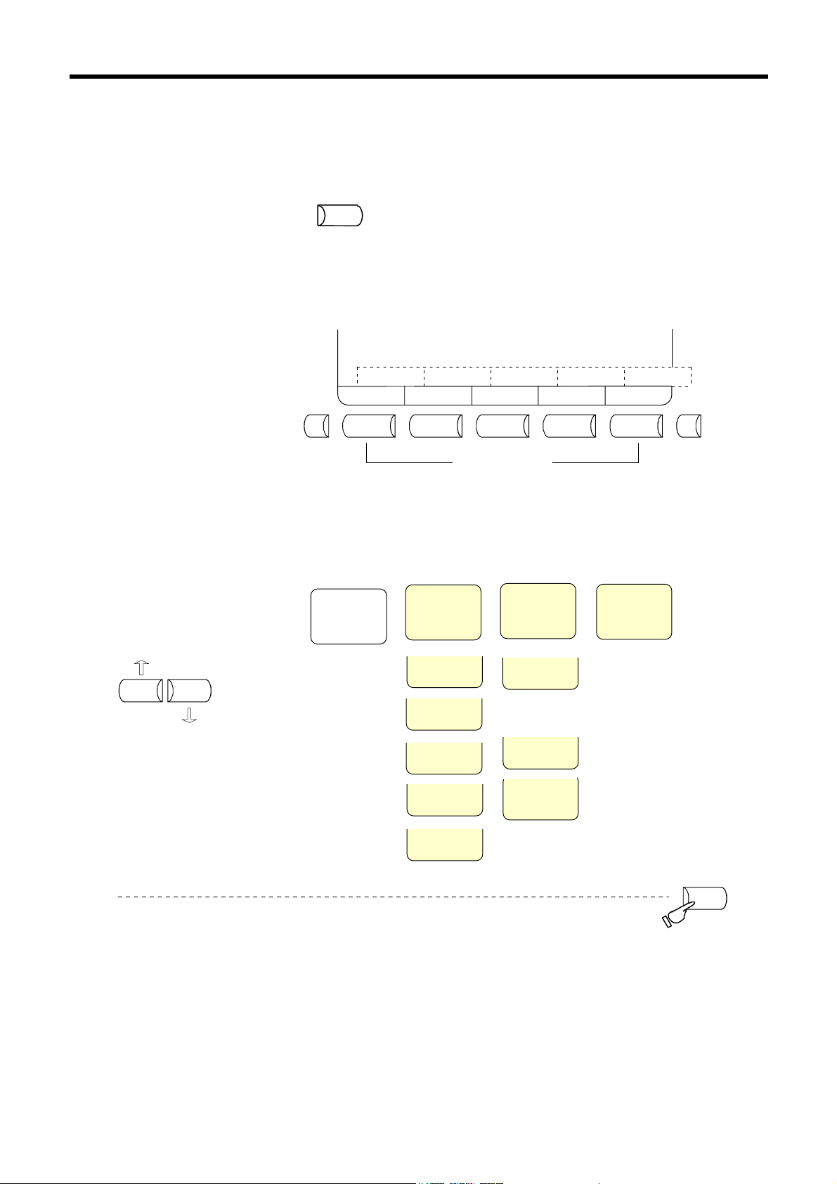
1. SCREEN CONFIGURATION
1.1 SCREEN TRANSITION CHARTS
1. SCREEN CONFIGURATION
1.1 SCREEN TRANSITION CHARTS
MENU
When the function selection key
TOOL menu is displayed after the power is turned on. To display PARAM menu‚ use menu key
on the TOOL screen.
is pressed‚ the following menu appears:
Tool offset menu display (No.1 to 4)
Setup parameter menu display (No. 1 to 4)
PARAM menu
No.1 to 4
Previous
page
Next
page
Previous
page Key
OFFSET REGIST
WORK
WORK
PROCESS
Menu selection key
PROCESS
#800 1 to #80 18
Machining
param eter
#8019 to #80 59
Machining
param et er
#8071 to #8086
CONTROL
PARAM
#810 1 to #8124
AXIS PARAM
#8201 to #8212
BARRI ER
PARAM
#8300 to #8319
I/O PAR
I/O BASE
PARAM
#9001 to #9014
I/O device
parameter
#9101 to #9130
#950 1 to #9530
Link
parameter
#9601 to #9630
LIFE
SETUP M EN U
.
.
.
MENU
Next page key
SETUP
PARAM ETE R
TOOL menu The contents of TOOL menu depends on the system.
II - 1
MENU
Page 100
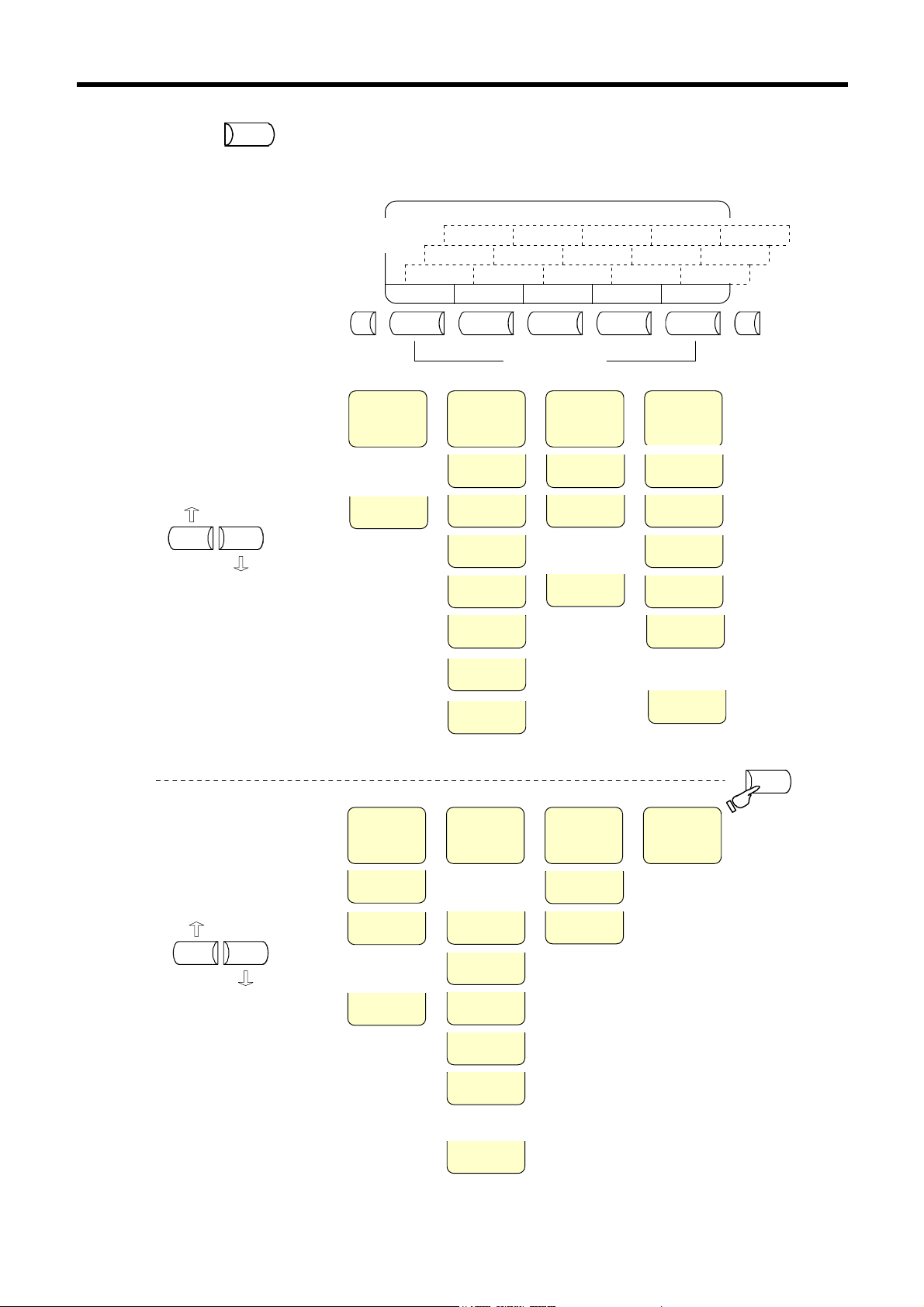
1. SCREEN CONFIGURATION
1.1 SCREEN TRANSITION CHARTS
SETUP
Press the menu key
to display the setup selection screen.
If the setup parameter menu opening option is specified in this screen, the setup parameters can be set up and
displayed.
Parameter menu display (No.1 to 4)
Tool offset menu display (No.1 to 4)
Setup param eter menu display (No. 5 to 8)
Setup param eter menu display (No. 1 to 4)
Previous page key
Setup parameter menu
No.1 to 4
Previous
page
Next
page
Base Axis Servo Spindle
Basic
speci fi cati on
param ete r
#100 1 to #1024
.
.
.
#192 5 to #1936
Work
Offset Registration
MC-ERR
Axis
specification
param ete r
#2001 to #2012
Axis specification
parameter
#201 3 to #20 24
Zero point
return parameter
#2025 to #2036
Zero point
return parameter
#2037 to #20 48
Absolute position
parameter
#204 9 to #2060
Axis specification
parameter
#2061 to #2072
Axis specification
parameter
#207 3 to #2084
Axis specification
parameter
#2085 to #2096
Process I/O PAR
PLC
Macro
Menu selection key
Servo
specification
param ete r
Servo
adjustment
param ete r
Servo
param ete r
#2201 to #2212
#2261 to #2265
Setup
Life
PSW
MENU
MENU
MENU
MENU
Next page key
Basic specific ation
parameter of
spindle
#300 1 to #30 36
Spindle
speci fi cati on
parameter
Spindle
specifi cation
.
.
.
parameter
Spindle offset
param ete r
Spindle offset
param ete r
Spindle
param ete r
#320 1 to #32 12
.
.
.
#357 3 to #35 84
Setup parameter menu
No.5 to 8
Previous
page
Next
page
Machining
error correction
#4000 to #40 47
Machining
error correction
#405 1 to #40 97
Machining
offset data
#410 1 to #41 84
.
.
.
#510 9 to #51 24
PLC timer
#6000 to #60 55
.
.
.
#6936 to #69 99
PLC counter
#6200 to #62 23
PLC constant
#6301 to #63 48
#6349 to #63 96
Bit selection
#6401 to #64 60
.
.
.
#6581 to #65 96
Macro list
M macro
#700 1 to #7103
G macro
#7201 to #73 13
ASCII macro
#7401 to #74 15
Positi on switch
#750 1 to #75 74
Menu
switch
II - 2
 Loading...