

Page 1

GROUP 80
CONFIGURATION
DIAGRAMS
CONTENTS
80-1
OVERALL CONFIGURATION DIAGRAM
OVERALL WIRING DIAGRAM
<SEDAN (LHD)> . . . . . . . . . . . . . . . . . . . . . 80-2
OVERALL WIRING DIAGRAM
<SEDAN (RHD)> . . . . . . . . . . . . . . . . . . . . 80-3
OVERALL WIRING DIAGRAM
<WAGON (LHD)> . . . . . . . . . . . . . . . . . . . . 80-4
OVERALL WIRING DIAGRAM
<WAGON (RHD)>. . . . . . . . . . . . . . . . . . . . 80-5
ENGINE COMPARTMENT
ENGINE COMPARTMENT <LHD>. . . . . . . 80-6
ENGINE COMPARTMENT <RHD> . . . . . . 80-8
ENGINE AND TRANSMISSION
ENGINE AND TRANSMISSION
<4G1-MPI (LHD)> . . . . . . . . . . . . . . . . . . . . 80-10
ENGINE AND TRANSMISSION
<4G1-MPI (RHD)> . . . . . . . . . . . . . . . . . . . 80-14
ENGINE AND TRANSMISSION
<4G6-MPI (LHD)> . . . . . . . . . . . . . . . . . . . . 80-18
ENGINE AND TRANSMISSION
<4G6-MPI (RHD)> . . . . . . . . . . . . . . . . . . . 80-22
DASH PANEL
DASH PANEL <LHD> . . . . . . . . . . . . . . . . . 80-26
DASH PANEL <RHD> . . . . . . . . . . . . . . . . . 80-32
FLOOR AND ROOF
FLOOR AND ROOF <SEDAN (LHD)> . . . . 80-38
FLOOR AND ROOF <SEDAN (RHD)> . . . . 80-40
FLOOR AND ROOF <WAGON (LHD)>. . . . 80-42
FLOOR AND ROOF <WAGON (RHD)> . . . 80-44
DOOR
DOOR <LHD> . . . . . . . . . . . . . . . . . . . . . . . 80-46
DOOR <RHD> . . . . . . . . . . . . . . . . . . . . . . . 80-48
TRUNK (LUGGAGE COMPARTMENT)
TRUNK (LUGGAGE COMPARTMENT)
<SEDAN (LHD)> . . . . . . . . . . . . . . . . . . . . . 80-50
TRUNK (LUGGAGE COMPARTMENT)
<SEDAN (RHD)>. . . . . . . . . . . . . . . . . . . . . 80-51
TAILGATE
TAILGATE <WAGON (LHD)> . . . . . . . . . . . 80-52
TAILGATE <WAGON (RHD)> . . . . . . . . . . . 80-53
Page 2
80-2
CONFIGURATION DIAGRAMS
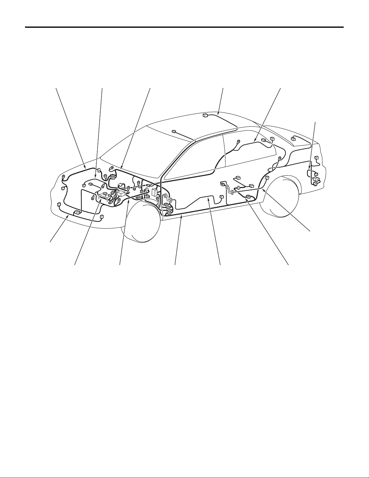
OVERALL CONFIGURATION DIAGRAM
OVERALL CONFIGURATION DIAGRAM
OVERALL WIRING DIAGRAM <SEDAN (LHD)>
M1801000101261
Front wiring
harness (RH)
Control wiring
harness
Instrument panel
wiring harness
Roof wiring
harness
Floor wiring
harness (RH)
Rear bumper
wiring harness
Front bumper
wiring harness
Battery wiring
harness
Front wiring
harness (LH)
Floor wiring
harness (LH)
NOTE: .
1. This illustration shows only major wiring harnesses.
2. *: also equipped at the right side.
Front door
wiring harness
Rear door
wiring harness
Fuel wiring
*
harness
AC301175
*
AB
Page 3
CONFIGURATION DIAGRAMS
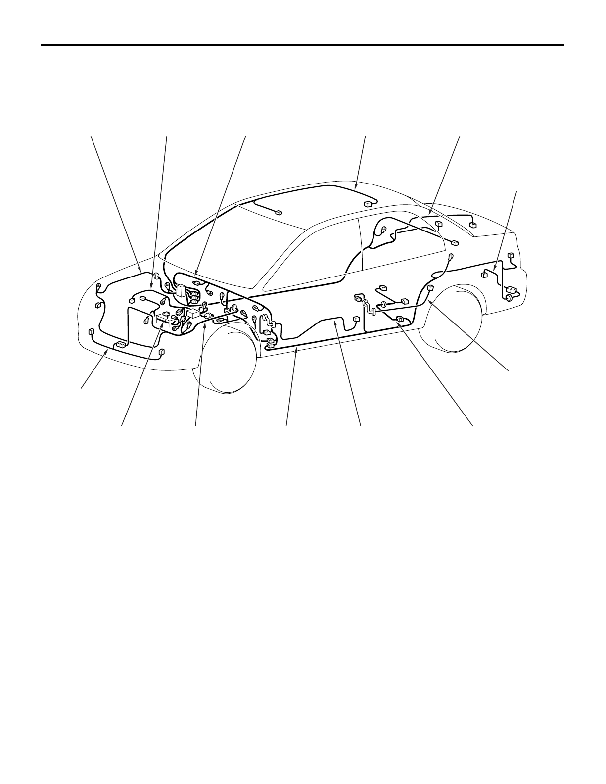
OVERALL CONFIGURATION DIAGRAM
OVERALL WIRING DIAGRAM <SEDAN (RHD)>
M1801000101272
80-3
Front wiring
harness (RH)
Front bumper
wiring harness
Control wiring
harness
Instrument panel
wiring harness
Roof wiring
harness
Floor wiring
harness (RH)
Rear bumper
wiring harness
Rear door
wiring harness
*
Battery wiring
harness
Front wiring
harness (LH)
Floor wiring
harness (LH)
NOTE: .
1. This illustration shows only major wiring harnesses.
2. *: also equipped at the right side.
Front door
wiring harness
Fuel wiring
*
harness
AC301176
AB
Page 4
80-4
CONFIGURATION DIAGRAMS
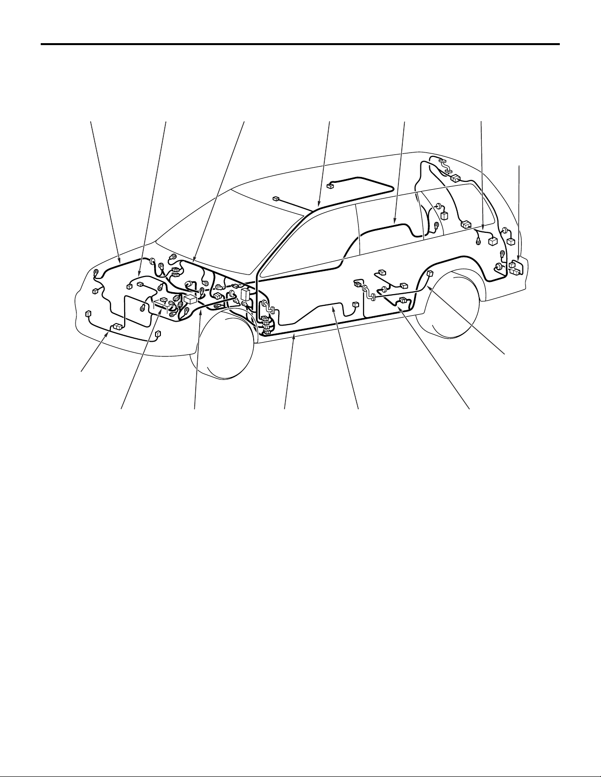
OVERALL CONFIGURATION DIAGRAM
OVERALL WIRING DIAGRAM <WAGON (LHD)>
M1801000101283
Front wiring
harness (RH)
Front bumper
wiring harness
Control wiring
harness
Instrument panel
wiring harness
Roof wiring
harness
Floor wiring
harness (RH)
Tailgate wiring
harness
Rear bumper
wiring harness
Rear door
wiring harness
*
Battery wiring
harness
Front wiring
harness (LH)
Floor wiring
harness (LH)
NOTE: .
1. This illustration shows only major wiring harnesses.
2. *: also equipped at the right side.
Front door
wiring harness
Fuel wiring
*
harness
AC301177
AB
Page 5
CONFIGURATION DIAGRAMS
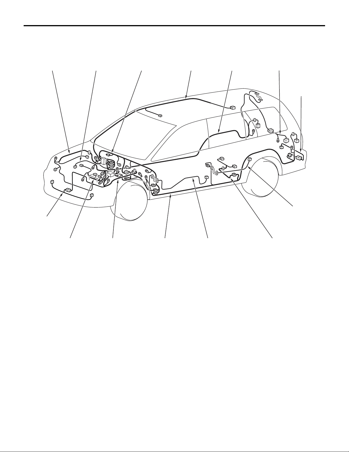
OVERALL CONFIGURATION DIAGRAM
OVERALL WIRING DIAGRAM <WAGON (RHD)>
M1801000101294
80-5
Front wiring
harness (RH)
Front bumper
wiring harness
Control wiring
harness
Instrument panel
wiring harness
Roof wiring
harness
Floor wiring
harness (RH)
Tailgate wiring
harness
Rear bumper
wiring harness
Rear door
wiring harness
*
Battery wiring
harness
Front wiring
harness (LH)
Floor wiring
harness (LH)
NOTE: .
1. This illustration shows only major wiring harnesses.
2. *: also equipped at the right side.
Front door
wiring harness
Fuel wiring
*
harness
AC301178
AB
Page 6
80-6
CONFIGURATION DIAGRAMS
ENGINE COMPARTMENT
ENGINE COMPARTMENT
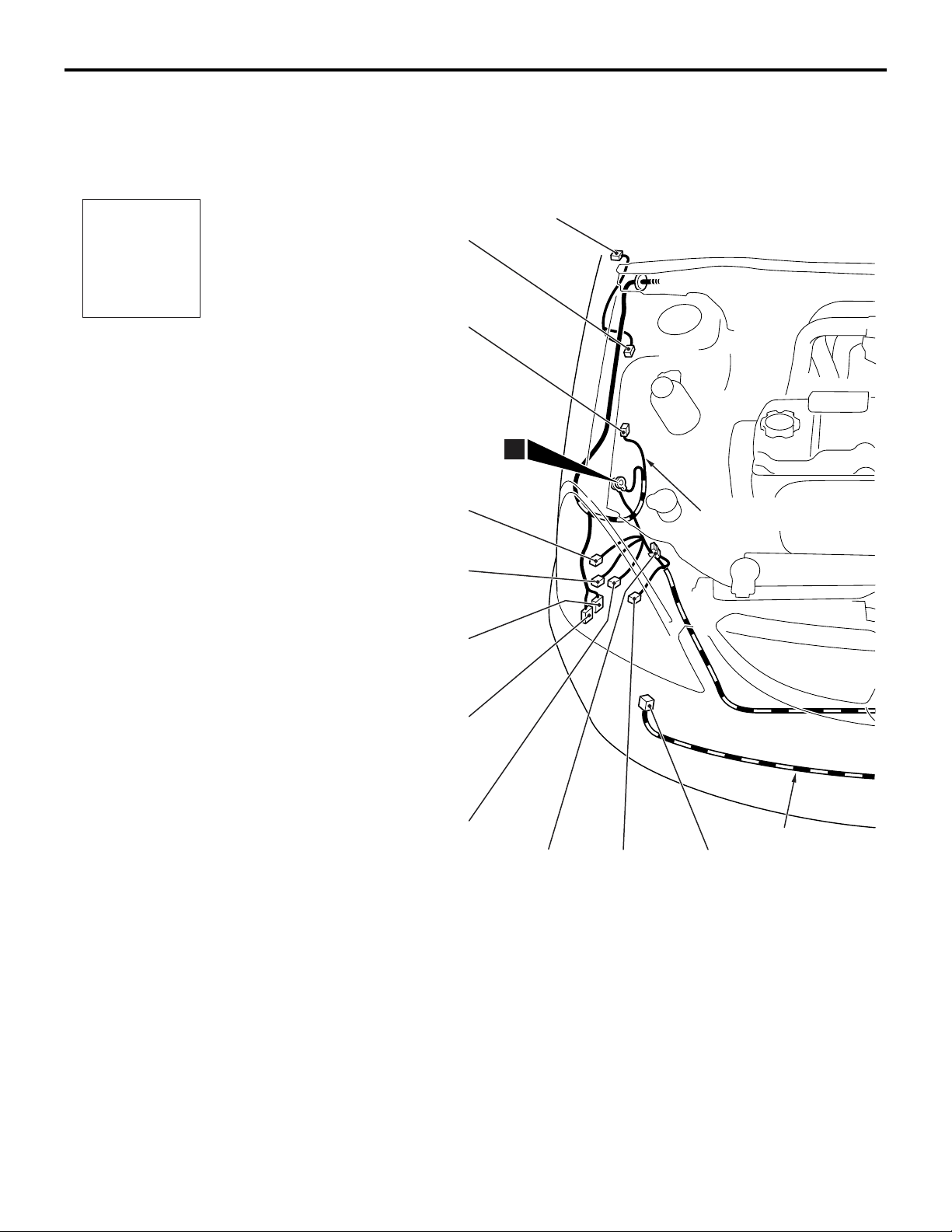
ENGINE COMPARTMENT <LHD>
Connector
symbol
A
M1801000302440
A-32
A-31
A-29
A-28
A-01
1
Front wiring
harness (RH)
A-27
Connector colour
code
B : Black
BR : Brown
G : Green
GR : Grey
L : Blue
None : Milk white
O : Orange
R : Red
V : Violet
Y : Yellow
A-01 (2-GR) Side turn signal lamp (RH)
A-02 (2-GR) Side turn signal lamp (LH)
A-03 (2-B) Wheel speed sensor (Front: LH)
A-04X (4) Front fog lamp relay or spare connector
(for front fog lamp)
A-05X (4) Horn relay
A-09X (4) Fan control relay
A-10X (11) Front-ECU
A-26
A-25
Front bumper
A-23A-24 A-22
A-11X (11) Front-ECU
A-12 (2-B) Front wiring harness (LH) and control
wiring harness combination
A-13 (12-B) Front wiring harness (LH) and control
wiring harness combination
A-14 (3-B) Headlamp (LH)
A-15 (6-B) Front combination lamp (LH)
A-16 (2) Front turn signal lamp (LH)
wiring harness
AC301123
AC
Page 7

CONFIGURATION DIAGRAMS
ENGINE COMPARTMENT
A-02
A-03
A-04X
A-05X
A-09X
A-10X
A-11X
A-12
80-7
Front wiring
harness (LH)
A-33
A-21
A-17 (2-B) Front fog lamp (LH)
A-18 (3-GR) Cooling fan motor drive control unit
A-19 (1-B) Horn (HI)
A-20 (2-B) Front wiring harness (LH) and front
bumper wiring harness combination
A-21 (1-B) Horn (LO)
A-22 (2-B) Front fog lamp (RH)
A-23 (2) Front turn signal lamp (RH)
A-24 (1) Spare connector (for front fog lamp)
A-13
12
A-14
A-15
A-16
A-17
A-18A-19A-20
AC502048
A-25 (6-B) Front combination lamp (RH)
A-26 (2) Windshield washer motor
A-27 (2-G) Rear washer motor
A-28 (2-B) Headlamp washer motor
A-29 (3-B) Headlamp (RH)
A-31 (2-BR) Dual pressure switch
A-32 (2-B) Wheel speed sensor (Front: RH)
A-33 (2-BR) Outside thermo sensor <Automatic A/C>
AB
Page 8
80-8
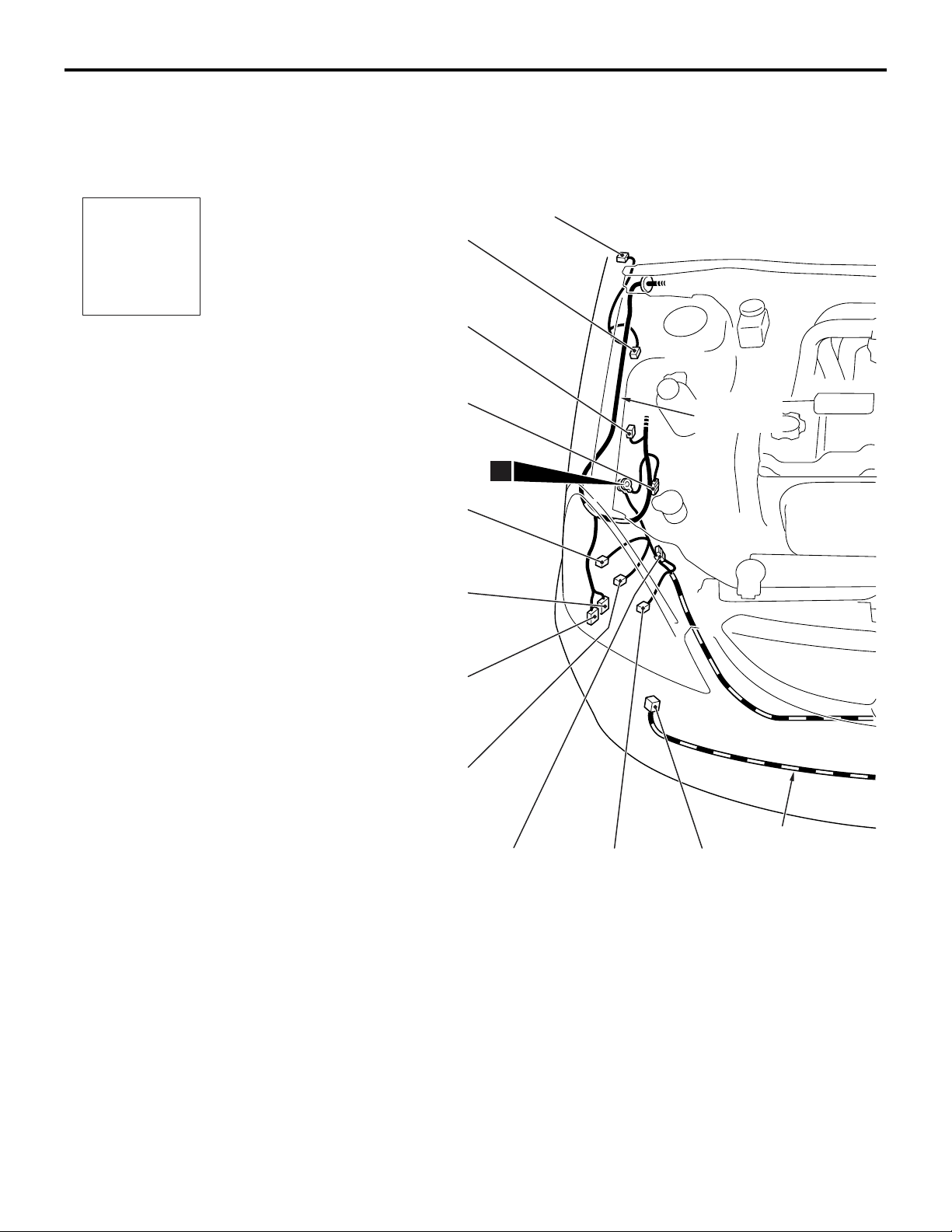
ENGINE COMPARTMENT <RHD>
CONFIGURATION DIAGRAMS
ENGINE COMPARTMENT
M1801000302451
Connector
symbol
A
A-32
A-31
A-30
A-29
A-27
A-01
Front wiring
harness (RH)
1
Connector colour
code
B : Black
BR : Brown
G : Green
GR : Grey
L : Blue
None : Milk white
O : Orange
R : Red
V : Violet
Y : Yellow
A-26
A-25
A-01 (2-GR) Side turn signal lamp (RH)
A-02 (2-GR) Side turn signal lamp (LH)
A-03 (2-B) Wheel speed sensor (Front: LH)
A-04X (4) Front fog lamp relay or spare connector
(for front fog lamp)
A-05X (4) Horn relay
A-09X (4) Fan control relay
A-10X (11) Front-ECU
Front bumper
A-23A-24 A-22
wiring harness
AC301126
A-11X (11) Front-ECU
A-12 (2-B) Front wiring harness (LH) and control
wiring harness combination
A-14 (3-B) Headlamp (LH)
A-15 (6-B) Front combination lamp (LH)
A-16 (2) Front turn signal lamp (LH)
A-17 (2-B) Front fog lamp (LH)
AC
Page 9
CONFIGURATION DIAGRAMS
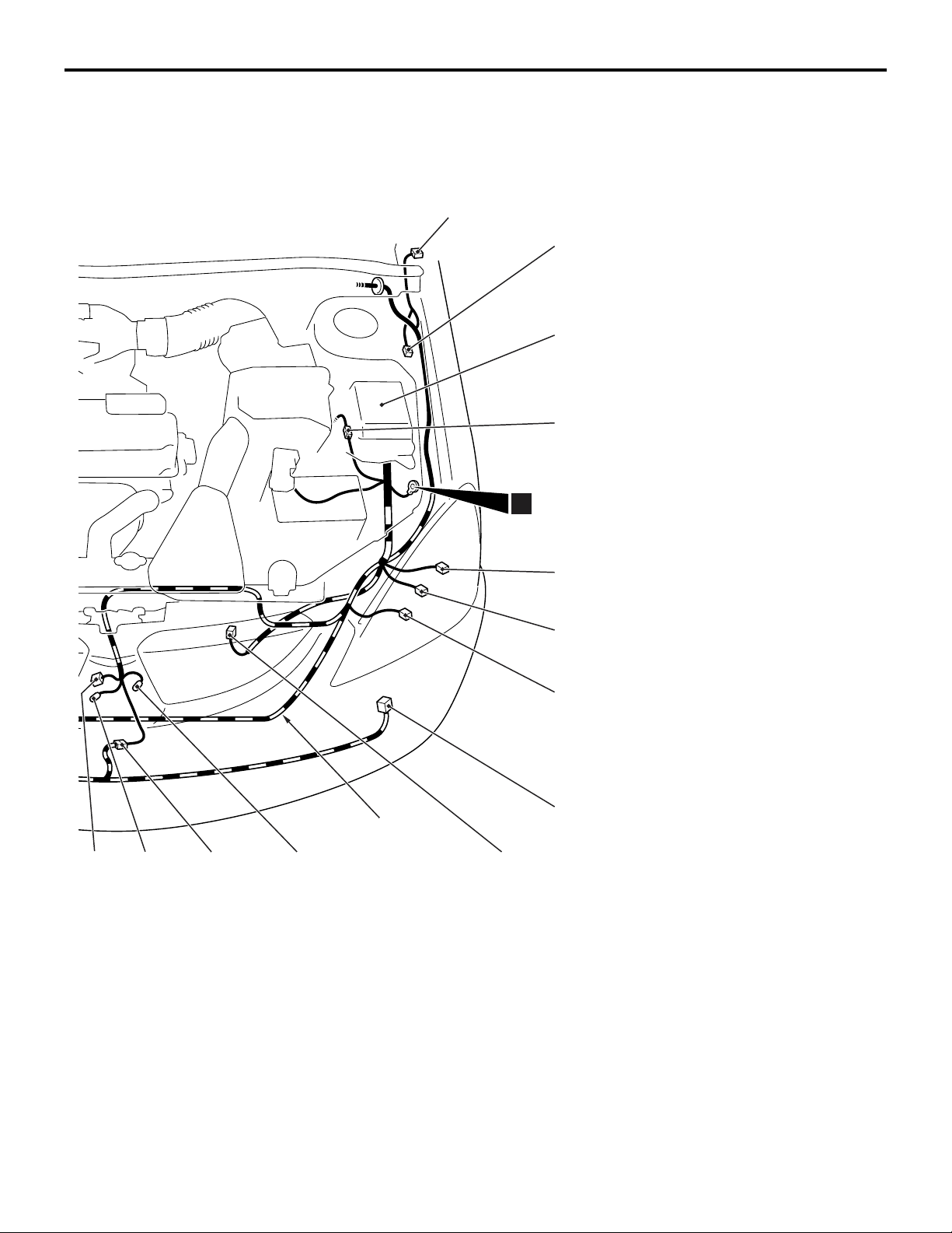
ENGINE COMPARTMENT
A-02
A-03
A-04X
A-05X
A-09X
A-10X
A-11X
A-12
80-9
A-33
A-21
Front wiring
harness (LH)
12
A-14
A-15
A-16
A-17
A-18A-19A-20
AC502049
AB
A-18 (3-GR) Cooling fan motor drive control unit
A-19 (1-B) Horn (HI)
A-20 (2-B) Front wiring harness (LH) and front
bumper wiring harness combination
A-21 (1-B) Horn (LO)
A-22 (2-B) Front fog lamp (RH)
A-23 (2) Front turn signal lamp (RH)
A-24 (1) Spare connector (for front fog lamp)
A-25 (6-B) Front combination lamp (RH)
A-26 (2) Windshield washer motor
A-27 (2-G) Rear washer motor
A-29 (3-B) Headlamp (RH)
A-30 (2-GR) No connection
A-31 (2-BR) Dual pressure switch
A-32 (2-B) Wheel speed sensor (Front: RH)
A-33 (2-BR) Outside thermo sensor <Automatic A/C>
Page 10

80-10
CONFIGURATION DIAGRAMS
ENGINE AND TRANSMISSION
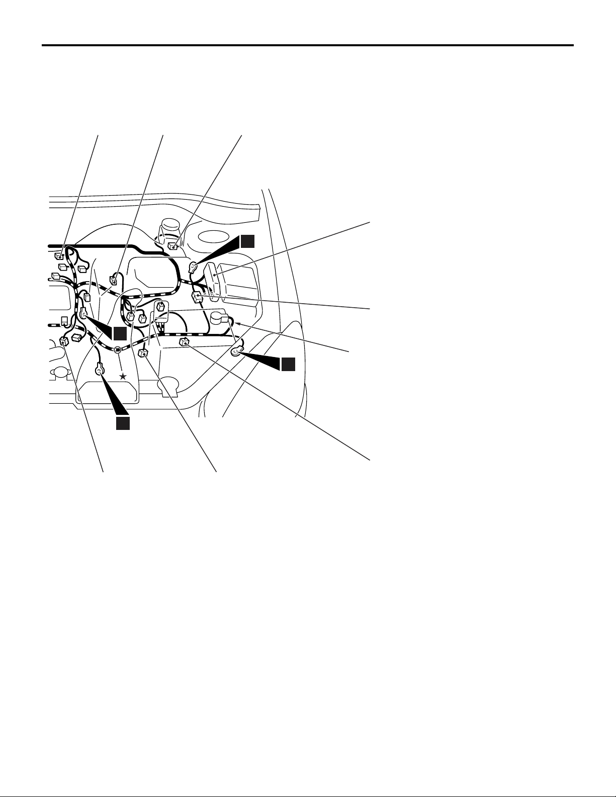
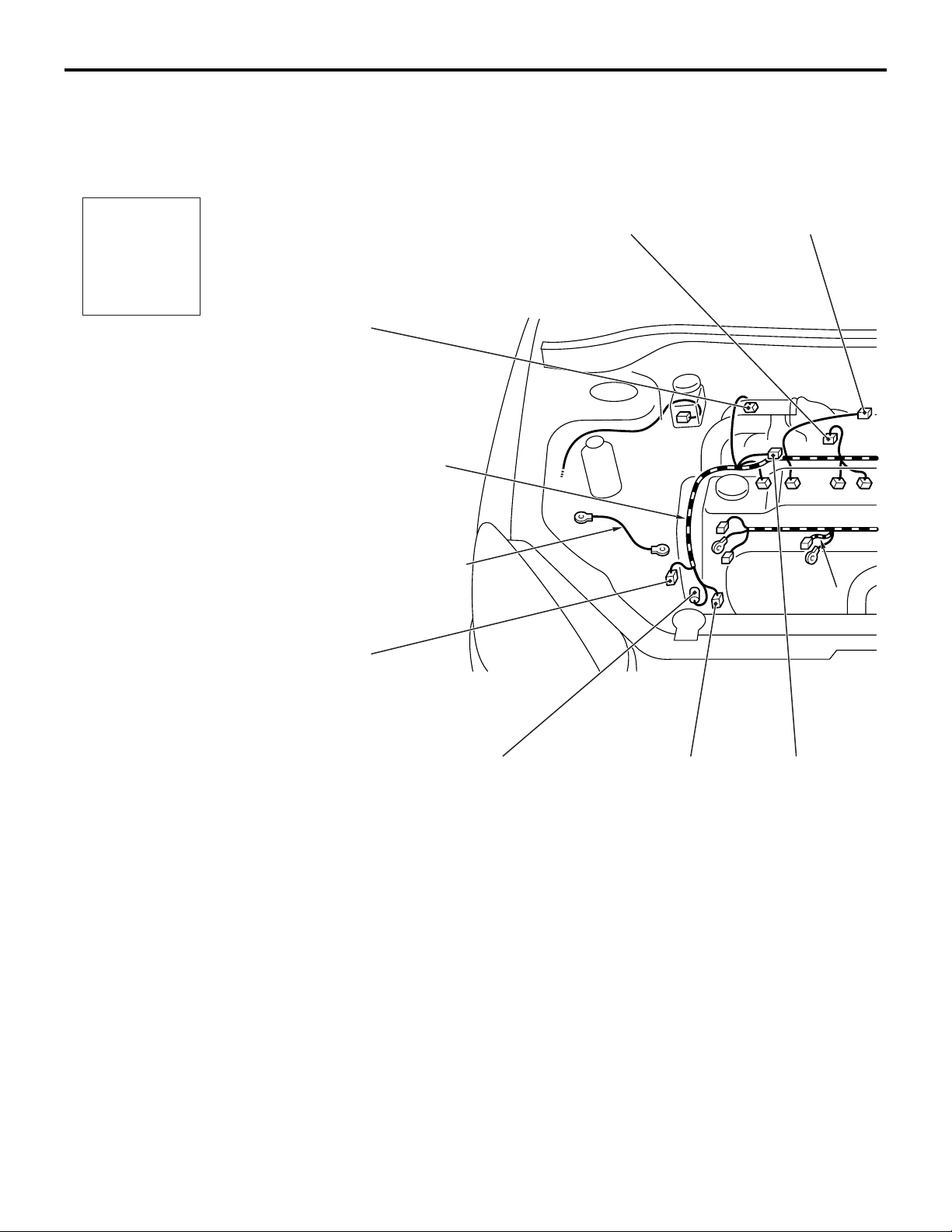
ENGINE AND TRANSMISSION
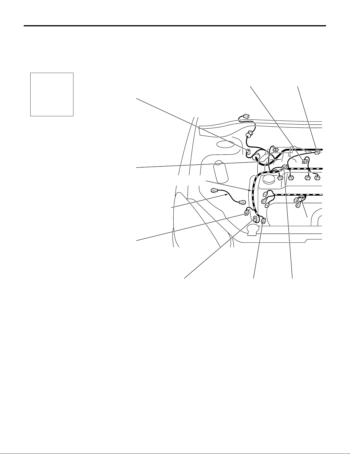
ENGINE AND TRANSMISSION <4G1-MPI (LHD)>
M1801000401949
Connector
symbol
-01
B
Connector colour
code
B : Black
BR : Brown
G : Green
GR : Grey
L : Blue
None : Milk white
O : Orange
R : Red
V : Violet
Y : Yellow
B-01 (5-GR) Windshield wiper motor
B-02 (2-GR) Fuel injector 1
B-03 (2-GR) Fuel injector 2
B-04 (2-GR) Fuel injector 3
B-05 (2-GR) Fuel injector 4
B-06 (3-GR) Throttle body throttle sensor
thru
-26
Control wiring
harness
B-26
Earth cable
B-25
B-24
B-07 (3-B) Vehicle speed sensor <M/T>
B-09 (2-GR) Brake fluid level indicator switch
B-10X (1) Engine speed detection connector
B-15X (4) A/T control relay
B-16X (4) Engine control relay
B-17X (4) A/C compressor relay
B-01
B-02
B-03
B-23
B-04
B-05
B-22
AC301129
*
AD
Page 11
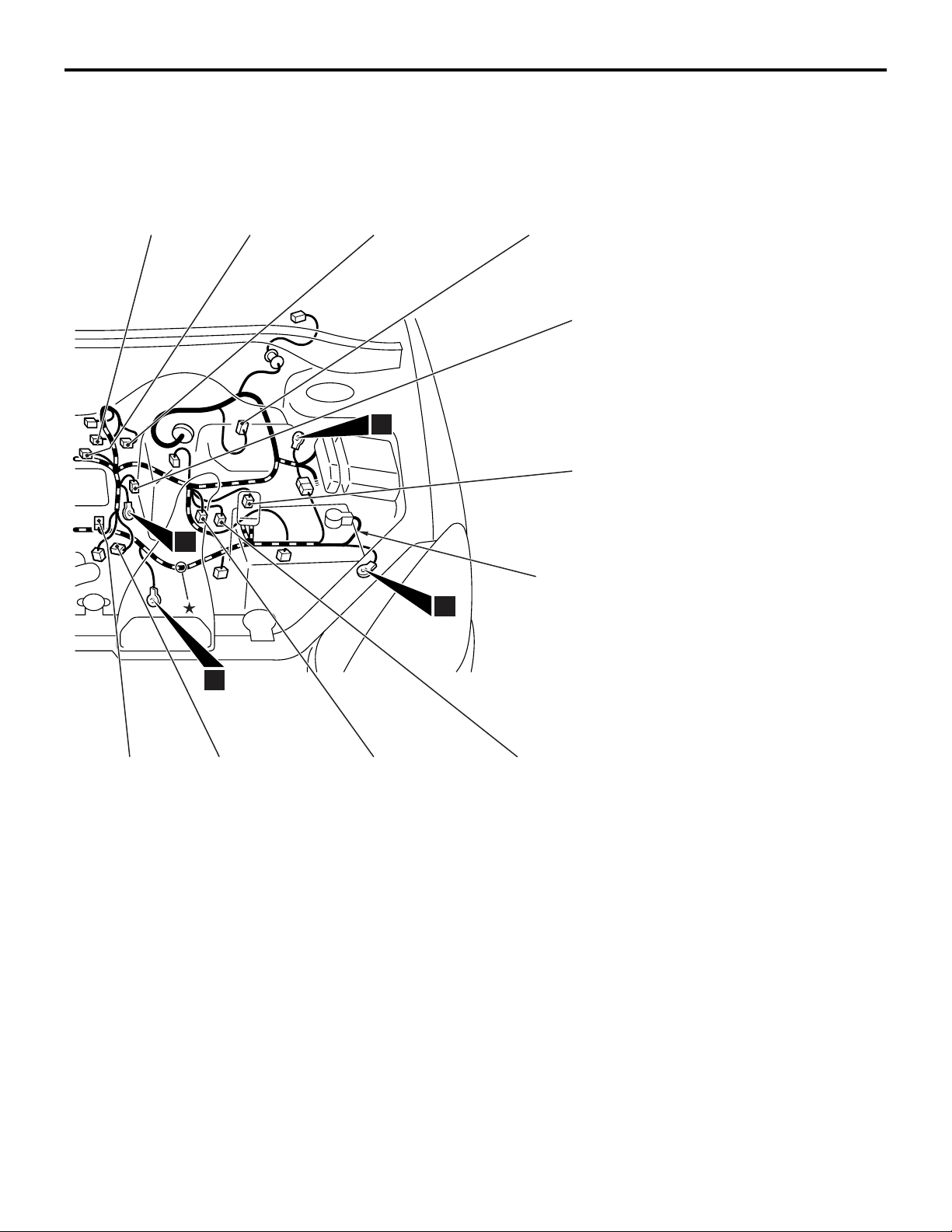
CONFIGURATION DIAGRAMS
ENGINE AND TRANSMISSION
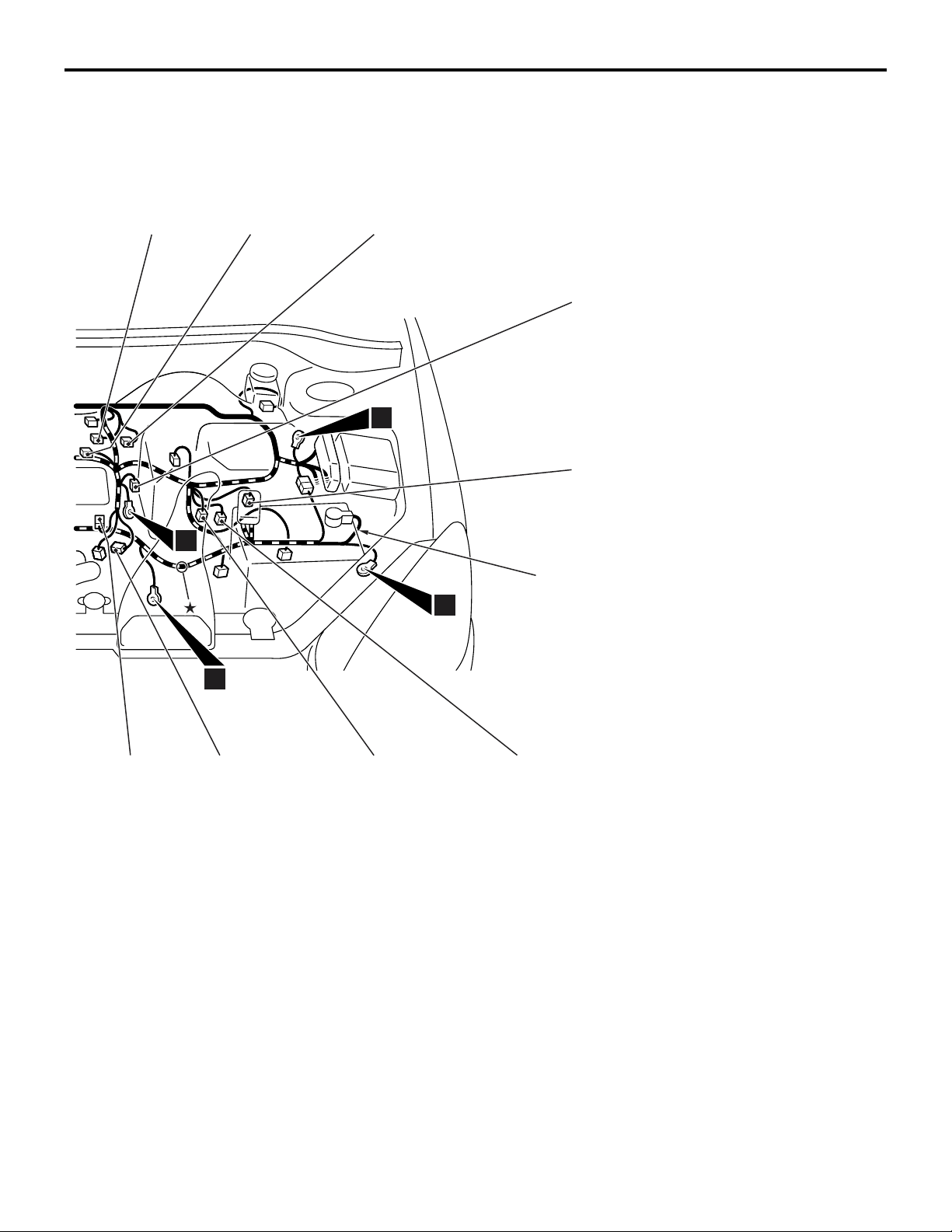
80-11
B-06
10
B-07
B-09
13
11
B-10X
B-15X
B-16X
B-17X
B-18
Battery wiring
harness
*
9
B-21
B-20
B-18 (6-B) Control wiring harness and battery wiring
harness combination
B-19 (10-GR) A/T control solenoid valve assembly
B-20 (10-B) Inhibitor switch <A/T>
B-21 (4-B) Engine control oxygen sensor (Front)
B-22 (1) Starter
B-23 (1-B) Starter
B-24 (1-B) Engine oil pressure switch
B-19
AC301130
B-25 (1) Alternator
B-26 (4-GR) Alternator
NOTE: On A/T only, the standard routing positions
for the corrugated tube and wiring harness are
marked by*.
AB
Page 12
80-12
CONFIGURATION DIAGRAMS
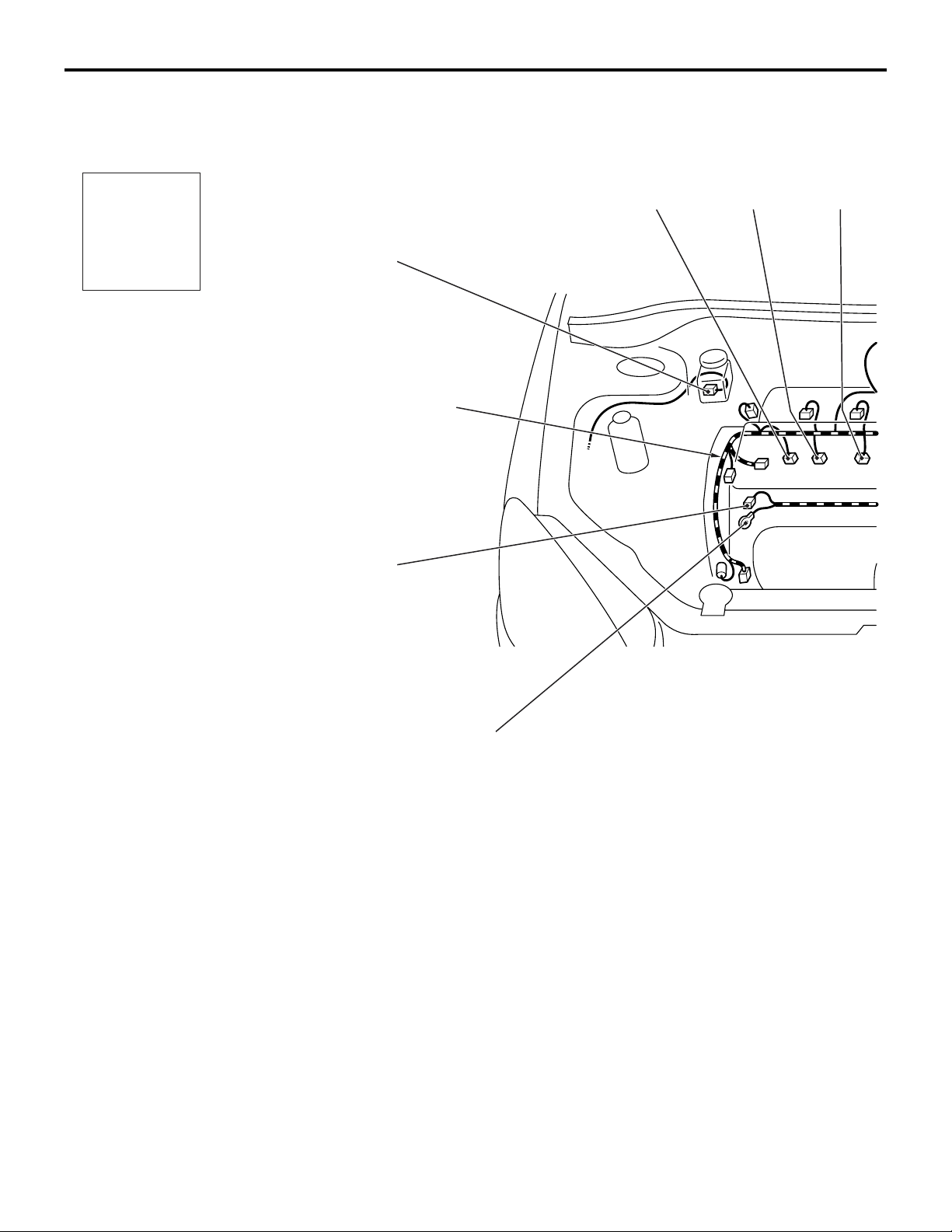
ENGINE AND TRANSMISSION
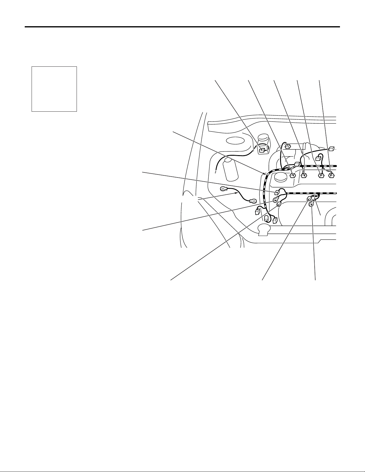
ENGINE AND TRANSMISSION <4G1-MPI (LHD)> (CONTINUED)
Connector
symbol
-101
B
Connector colour
code
B : Black
BR : Brown
G : Green
GR : Grey
L : Blue
None : Milk white
O : Orange
R : Red
V : Violet
Y : Yellow
thru
-118
B-118
B-117
B-116
Earth cable
Control wiring
harness
B-115
B-101 B-102
B-114
B-113
AC301129
*
AE
B-101 (2-BR) Emission solenoid valve (EGR system)
B-102 (4-GR) Inlet manifold absolute pressure sensor
B-103 (6-B) Throttle body idle speed control servo
B-104 (3-GR) Ignition coil 1
B-105 (2-B) Emission solenoid valve (Purge control
system)
B-107 (3-B) Camshaft position sensor
B-108 (3-GR) Output shaft speed sensor <A/T>
B-109 (3-B) Input shaft speed sensor <A/T>
B-110 (2-B) Back-up lamp switch <M/T>
B-111 (2-B) Water temperature sensor unit
Page 13
CONFIGURATION DIAGRAMS
ENGINE AND TRANSMISSION
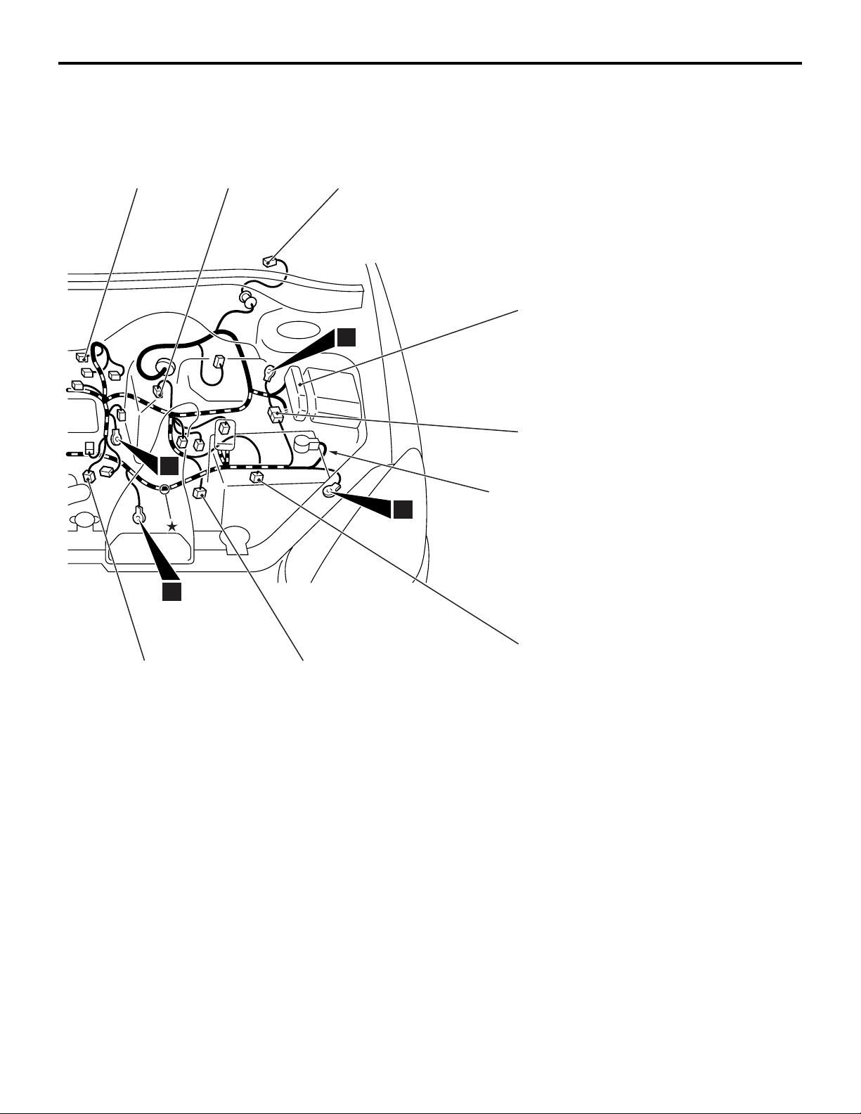
80-13
B-103
10
B-104
*
B-105
B-107
13
B-108
Battery wiring
harness
11
9
B-112
B-111
B-110
B-112 (1-B) Water temperature gauge unit
B-113 (3-GR) Ignition coil 2
B-114 (1-B) A/C compressor
B-115 (1) Power steering fluid pressure switch
B-116 (3-B) Engine crank angle sensor
B-117 (2-GR) Engine control detonation sensor
B-118 (28-GR) ABS-ECU
B-109
AC301130
NOTE: On A/T only, the standard routing positions
for the corrugated tube and wiring harness are
marked by*.
AC
Page 14
80-14
CONFIGURATION DIAGRAMS
ENGINE AND TRANSMISSION
ENGINE AND TRANSMISSION <4G1-MPI (RHD)>
M1801000401950
Connector
symbol
-01
B
Connector colour
code
B : Black
BR : Brown
G : Green
GR : Grey
L : Blue
None : Milk white
O : Orange
R : Red
V : Violet
Y : Yellow
thru
-26
Control wiring
harness
B-26
B-25
Earth cable
B-24
B-09
B-02
B-23
B-03
B-04 B-05
B-22
AC301132
*
AD
B-01 (5-GR) Windshield wiper motor
B-02 (2-GR) Fuel injector 1
B-03 (2-GR) Fuel injector 2
B-04 (2-GR) Fuel injector 3
B-05 (2-GR) Fuel injector 4
B-06 (3-GR) Throttle body throttle sensor
B-07 (3-B) Vehicle speed sensor <M/T>
B-09 (2-GR) Brake fluid level indicator switch
B-10X (1) Engine speed detection connector
B-14X (4) Ignition coil relay
B-15X (4) A/T control relay
B-16X (4) Engine control relay
Page 15
CONFIGURATION DIAGRAMS
ENGINE AND TRANSMISSION
80-15
B-06
10
B-07
B-01
13
11
B-10X
B-14X
B-15X
B-16X
B-17X
B-18
Battery wiring
harness
*
9
B-21
B-20
B-17X (4) A/C compressor relay
B-18 (6-B) Control wiring harness and battery wiring
harness combination
B-19 (10-GR) A/T control solenoid valve assembly
B-20 (10-B) Inhibitor switch <A/T>
B-21 (4-B) Engine control oxygen sensor (Front)
B-22 (1) Starter
B-23 (1-B) Starter
B-24 (1-B) Engine oil pressure switch
B-19
AC301133
B-25 (1) Alternator
B-26 (4-GR) Alternator
NOTE: On A/T only, the standard routing positions
for the corrugated tube and wiring harness are
marked by*.
AB
Page 16
80-16
CONFIGURATION DIAGRAMS
ENGINE AND TRANSMISSION
ENGINE AND TRANSMISSION <4G1-MPI (RHD)> (CONTINUED)
Connector
symbol
-101
B
Connector colour
code
B : Black
BR : Brown
G : Green
GR : Grey
L : Blue
None : Milk white
O : Orange
R : Red
V : Violet
Y : Yellow
thru
-118
B-117
Control wiring
harness
B-116
Earth cable
B-115
B-101 B-102
B-114
B-113
AC301132
*
AE
B-101 (2-BR) Emission solenoid valve (EGR system)
B-102 (4-GR) Inlet manifold absolute pressure sensor
B-103 (6-B) Throttle body idle speed control servo
B-104 (3-GR) Ignition coil 1
B-105 (2-B) Emission solenoid valve (Purge control
system)
B-107 (3-B) Camshaft position sensor
B-108 (3-GR) Output shaft speed sensor <A/T>
B-109 (3-B) Input shaft speed sensor <A/T>
B-110 (2-B) Back-up lamp switch <M/T>
Page 17
CONFIGURATION DIAGRAMS
ENGINE AND TRANSMISSION
80-17
B-103
10
B-104
*
B-105
13
11
B-118
B-107
B-108
Battery wiring
harness
9
B-112
B-111
B-110
B-111 (2-B) Water temperature sensor unit
B-112 (1-B) Water temperature gauge unit
B-113 (3-GR) Ignition coil 2
B-114 (1-B) A/C compressor
B-115 (1) Power steering fluid pressure switch
B-116 (3-B) Engine crank angle sensor
B-117 (2-GR) Engine control detonation sensor
B-109
AC301133
B-118 (28-GR) ABS-ECU
NOTE: On A/T only, the standard routing positions
for the corrugated tube and wiring harness are
marked by*.
AC
Page 18

80-18
CONFIGURATION DIAGRAMS
ENGINE AND TRANSMISSION
ENGINE AND TRANSMISSION <4G6-MPI (LHD)>
M1801000401961
Connector
symbol
-01
B
Connector colour
code
B : Black
BR : Brown
G : Green
GR : Grey
L : Blue
None : Milk white
O : Orange
R : Red
V : Violet
Y : Yellow
thru
-26
B-26
B-25
Control wiring
harness
B-01
B-02
B-03
B-04
AC301135
AD
B-01 (5-GR) Windshield wiper motor
B-02 (2-GR) Fuel injector 1
B-03 (2-GR) Fuel injector 2
B-04 (2-GR) Fuel injector 3
B-05 (2-GR) Fuel injector 4
B-06 (4-B) Throttle body throttle sensor
B-07 (3-B) Vehicle speed sensor <M/T>
B-08 (7-B) Air cleaner air flow sensor
B-09 (2-GR) Brake fluid level indicator switch
B-10X (1) Engine speed detection connector
B-15X (4) A/T control relay
Page 19

CONFIGURATION DIAGRAMS
ENGINE AND TRANSMISSION
80-19
Earth
cable
10
B-05
13
B-08
11
B-09
B-10X
B-15X
B-16X
B-17X
B-18
Battery wiring
harness
B-06
9
B-07
B-24
B-23
B-22
B-21
B-20
B-16X (4) Engine control relay
B-17X (4) A/C compressor relay
B-18 (6-B) Control wiring harness and battery wiring
harness combination
B-19 (10-GR) A/T control solenoid valve assembly
B-20 (10-B) Inhibitor switch <A/T>
B-19
AC502050
B-21 (4-B) Engine control oxygen sensor (Front)
B-22 (1) Start er
B-23 (1-B) Starter
B-24 (1-B) Engine oil pressure switch
B-25 (1) Alternator
B-26 (4-GR) Alternator
AB
Page 20

80-20
CONFIGURATION DIAGRAMS
ENGINE AND TRANSMISSION
ENGINE AND TRANSMISSION <4G6-MPI (LHD)> (CONTINUED)
Connector
symbol
-101
B
Connector colour
code
B : Black
BR : Brown
G : Green
GR : Grey
L : Blue
None : Milk white
O : Orange
R : Red
V : Violet
Y : Yellow
thru
-118
B-118
B-117
B-116
Control wiring
harness
B-115
B-105
B-114
B-113
B-101
AC301135
AE
B-101 (2-BR) Emission solenoid valve (EGR system)
B-103 (6-B) Throttle body idle speed control servo
B-104 (3-GR) Ignition coil 1
B-105 (2-B) Emission solenoid valve (Purge control
system)
B-106 (1-B) Capacitor
B-107 (3-B) Camshaft position sensor
B-108 (3-GR) Output shaft speed sensor <A/T>
B-109 (3-B) Input shaft speed sensor <A/T>
B-110 (2-B) Back-up lamp switch <M/T>
Page 21

CONFIGURATION DIAGRAMS
ENGINE AND TRANSMISSION
80-21
Earth cable
10
B-103
9
B-104
13
B-106
B-112
B-108
Battery wiring
harness
11
B-107
B-111
B-111 (2-B) Water temperature sensor unit
B-112 (1-B) Water temperature gauge unit
B-113 (3-GR) Ignition coil 2
B-114 (1-B) A/C compressor
B-110
B-109
AC502050
B-115 (1-B) Power steering fluid pressure switch
B-116 (3-B) Engine crank angle sensor
B-117 (2-GR) Engine control detonation sensor
B-118 (28-GR) ABS-ECU
AC
Page 22
80-22
CONFIGURATION DIAGRAMS
ENGINE AND TRANSMISSION
ENGINE AND TRANSMISSION <4G6-MPI (RHD)>
M1801000401972
Connector
symbol
-01
B
Connector colour
code
B : Black
BR : Brown
G : Green
GR : Grey
L : Blue
None : Milk white
O : Orange
R : Red
V : Violet
Y : Yellow
thru
-26
B-09
Control wiring
harness
B-26
B-25
B-02
B-03
B-04
AC301138
AD
B-01 (5-GR) Windshield wiper motor
B-02 (2-GR) Fuel injector 1
B-03 (2-GR) Fuel injector 2
B-04 (2-GR) Fuel injector 3
B-05 (2-GR) Fuel injector 4
B-06 (4-B) Throttle body throttle sensor
B-07 (3-B) Vehicle speed sensor
B-08 (7-B) Air cleaner air flow sensor
B-09 (2-GR) Brake fluid level indicator switch
B-10X (1) Engine speed detection connector
B-14X (4) Ignition coil relay
Page 23

CONFIGURATION DIAGRAMS
ENGINE AND TRANSMISSION
80-23
Earth
cable
10
B-05
B-06
9
B-07
B-01
13
11
B-08
B-10X
B-14X
B-16X
B-17X
B-18
Battery wiring
harness
B-24
B-23
B-22
B-16X (4) Engine control relay
B-17X (4) A/C compressor relay
B-18 (6-B) Control wiring harness and battery wiring
harness combination
B-21 (4-B) Engine control oxygen sensor (Front)
B-21
B-22 (1) Start er
B-23 (1-B) Starter
B-24 (1-B) Engine oil pressure switch
B-25 (1) Alternator
B-26 (4-GR) Alternator
AC301139
AB
Page 24

80-24
CONFIGURATION DIAGRAMS
ENGINE AND TRANSMISSION
ENGINE AND TRANSMISSION <4G6-MPI (RHD)> (CONTINUED)
Connector
symbol
-101
B
Connector colour
code
B : Black
BR : Brown
G : Green
GR : Grey
L : Blue
None : Milk white
O : Orange
R : Red
V : Violet
Y : Yellow
thru
-118
B-117
B-116
Control wiring
harness
B-115
B-105 B-101
B-114
B-113
AC301138
AE
B-101 (2-BR) Emission solenoid valve (EGR system)
B-103 (6-B) Throttle body idle speed control servo
B-104 (3-GR) Ignition coil 1
B-105 (2-B) Emission solenoid valve (Purge control
system)
B-106 (1-B) Capacitor
B-107 (3-B) Camshaft position sensor
B-110 (2-B) Back-up lamp switch
Page 25

CONFIGURATION DIAGRAMS
ENGINE AND TRANSMISSION
80-25
Earth cable
10
B-103
9
B-104
B-106
B-118
13
B-112
Battery wiring
harness
11
B-107
B-111 (2-B) Water temperature sensor unit
B-112 (1-B) Water temperature gauge unit
B-113 (3-GR) Ignition coil 2
B-114 (1-B) A/C compressor
B-111
B-110
AC301139
B-115 (1-B) Power steering fluid pressure switch
B-116 (3-B) Engine crank angle sensor
B-117 (2-GR) Engine control detonation sensor
B-118 (28-GR) ABS-ECU
AC
Page 26

80-26
CONFIGURATION DIAGRAMS
DASH PANEL
DASH PANEL
DASH PANEL <LHD>
Connector
symbol
-01
C
thru
-40
M1801000601761
C-36
C-35
C-34
C-33
C-32
C-01
C-02
16
C-04C-03
C-05
C-38 C-06
6
C-31
C-29
Connector colour
code
B : Black
BR : Brown
G : Green
GR : Grey
L : Blue
None : Milk white
O : Orange
R : Red
V : Violet
Y : Yellow
C-40
C-27
C-01 (6) Fog lamp switch
C-02 (1) Spare connector (for front fog lamp
switch)
C-03 (22-B) J/C (5)
C-04 (21) Combination meter
C-05 (4) Stop lamp switch
C-06 (21-L) Combination meter
C-08 (1-B) Spare connector (for audio)
C-09 (14) Spare connector (for audio)
C-10 (1) Instrument panel wiring harness and
antenna feeder cable combination
C-11 (16-B) Diagnosis connector
J/B
C-25
C-24
C-22
C-21
AC502051
C-12 (33) J/C (6)
C-13 (25) Instrument panel wiring harness and
control wiring harness combination
C-14 (10-GR) Instrument panel wiring harness and
control wiring harness combination
C-15 (22-L) Instrument panel wiring harness and
control wiring harness combination
C-19 (12) Diagnosis connector
C-21 (3) Front wiring harness (LH) and instrument
panel wiring harness combination
AB
Page 27

CONFIGURATION DIAGRAMS
DASH PANEL
80-27
Instrument panel
wiring harness
5
C-08C-39
C-09
C-10
C-11
C-12
Control wiring
harness
14
15
C-19
C-15
C-22 (13) Instrument panel wiring harness and floor
wiring harness (LH) combination
C-24 (6-L) Instrument panel wiring harness and roof
wiring harness combination
C-25
(11-B*)
Instrument panel wiring harness and floor
wiring harness (LH) combination
C-27 (25) Front wiring harness (LH) and instrument
panel wiring harness combination
C-29 (20) Instrument panel wiring harness and front
door wiring harness (LH) combination
C-31 (6) Instrument panel wiring harness and roof
wiring harness combination <Wagon>
C-32 (22-B) J/C (4)
C-33 (6-L) Rheostat
C-13
C-14
AC502052
AB
C-34 (6-GR) Headlamp levelling switch
C-35 (22-L) J/C (2)
C-36 (11-B) Remote controlled mirror switch
C-38 (5) Photo sensor <Automatic A/C>
C-39 (2-B) Inside air temperature sensor <Automatic
A/C>
C-40 (2) Front wiring harness (LH) and instrument
panel wiring harness combination
<Automatic A/C>
NOTE: The connector colour marked by * is for the
female side. For the male side, the colour is grey for
Sedan, and milk white for Wagon.
Page 28

80-28
DASH PANEL <LHD> (CONTINUED)
CONFIGURATION DIAGRAMS
DASH PANEL
Connector
symbol
-101
C
thru
-149
C-140
C-139
C-148
C-147
C-101
C-102
C-103
C-141
4
Instrument panel
Connector colour
code
B : Black
BR : Brown
G : Green
GR : Grey
L : Blue
None : Milk white
O : Orange
R : Red
V : Violet
Y : Yellow
wiring harness
C-133
C-132
C-101 (4) Hazard warning lamp switch
C-102 (4) Clock
C-103 (22-GR) J/C (1)
C-104 (22-GR) J/C (3)
C-106 (7) Instrument panel wiring harness and A/C
wiring harness combination <Manual
A/C>
C-107 (7) Outside /Inside air selection damper
control motor
C-108 (2-R) Air bag module (squib) <Passenger’s
side>
C-109 (4) Resistor <Manual A/C>
C-110 (2) Blower motor <Manual A/C>
C-112 (16) Instrument panel wiring harness and front
door wiring harness (RH) combination
Y
C-131
C-130
C-146 C-145
AC502053
AB
C-114 (25) Front wiring harness (RH) and instrument
panel wiring harness combination
C-116
(9-GR*)
Instrument panel wiring harness and floor
wiring harness (RH) combination
C-119 (13) Instrument panel wiring harness and floor
wiring harness (RH) combination
C-122 (35-GR) Engine-A/T-ECU <A/T>
C-123 (26-Y) Engine-ECU <M/T>
C-124 (26-GR) Engine-A/T-ECU <A/T>
C-125 (16-Y) Engine-ECU <M/T>
C-126 (28-GR) Engine-A/T-ECU <A/T>
C-127 (12-Y) Engine-ECU <M/T>
C-128 (30-GR) Engine-A/T-ECU <A/T>
C-129 (22-Y) Engine-ECU <M/T>
C-130 (4) Engine control oxygen sensor (Rear)
C-131 (20-Y) SRS-ECU
Page 29

Antenna
feeder
cable
C-142
C-104
C-106
C-143
A/C wiring
harness
CONFIGURATION DIAGRAMS
DASH PANEL
C-107
80-29
C-108
C-109
Control wiring
harness
C-128
C-129
C-126
C-127
C-124
C-125
C-122
C-123
C-119
C-132 (28-Y) SRS-ECU
C-133 (20-Y) SRS-ECU
C-139 (16-B) A/C-ECU or heater control unit
C-140 (6) Blower switch
C-141 (6) Air mixing door control motor and
potentiometer <Automatic A/C>
C-142 (2) Air thermo sensor <Automatic A/C>
C-143 (13) Instrument panel wiring harness and A/C
wiring harness combination <Automatic
A/C>
C-144 (6) Blower motor <Automatic A/C>
C-145 (6) Mode selection damper control motor and
potentiometer <Automatic A/C>
3
C-149
2
C-110
C-144
C-112
C-114
C-116
AC502054
C-146 (2) Heater water temperature sensor
<Automatic A/C>
C-147 (20-B) A/C-ECU <Automatic A/C>
C-148 (16-B) A/C-ECU <Automatic A/C>
C-149 (2) Instrument panel wiring harness and
tweeter wiring harness combination
NOTE: The connector colour marked by * is for the
female side.For the male side, the colour is grey for
Sedan, and milk white for Wagon.
AB
Page 30

80-30
DASH PANEL <LHD> (CONTINUED)
Connector
symbol
-201
C
thru
-227
CONFIGURATION DIAGRAMS
DASH PANEL
STEERING COLUMN
C-207
C-206
Clock spring
Y
Instrument panel
wiring harness
C-201C-202C-203C-203C-204C-205
AC301179
AB
C-201 (6) Ignition switch
C-202 (7) Key reminder switch
C-203 (10) Column switch
C-204 (6) Clock spring
C-205 (4-Y) Clock spring
C-206 (1) Horn switch
C-207 (2) Air bag module (squib) <Driver’s side>
C-208 (13) Instrument panel wiring harness and J/B
combination
C-209 (14) Instrument panel wiring harness and J/B
combination
C-210 (6) Instrument panel wiring harness and J/B
combination
C-211 (1-B) Instrument panel wiring harness and J/B
combination
C-212 (28) Instrument panel wiring harness and J/B
combination
Page 31

CONFIGURATION DIAGRAMS
DASH PANEL
JUNCTION BLOCK
80-31
C-224
C-223
C-222
C-221
C-220
(Front view)
C-208 C-209 C-210 C-211
(Rear view)
C-225
C-212
C-213
C-214
C-215
C-217C-218C-219
C-213 (5) Rear window defogger relay
C-214 (5) Blower relay
C-215 (15) Floor wiring harness (LH) and J/B
combination
C-217 (3) Roof wiring harness and J/B combination
C-218 (4) Rear fog lamp relay
C-219 (4) Accessory socket relay
C-220 (4) Fuel pump relay (2)
C-226C-227
C-221 (4) Heated seat relay
C-222 (4) Fuel pump relay (1)
C-223 (5) Power window relay
C-224 (2) No connection
C-225 (20) ETACS-ECU
C-226 (24) ETACS-ECU
C-227 (24-GR) ETACS-ECU
Connector colour
code
B : Black
BR : Brown
G : Green
GR : Grey
L : Blue
None : Milk white
O : Orange
R : Red
V : Violet
Y : Yellow
AC302010
AC
Page 32

80-32
DASH PANEL <RHD>
CONFIGURATION DIAGRAMS
DASH PANEL
M1801000601772
Connector
symbol
-01
C
thru
-39
C-10
C-11
C-37
C-09 C-08
Control wiring
harness
C-38
Instrument panel
wiring harness
4
Connector colour
code
B : Black
BR : Brown
G : Green
GR : Grey
L : Blue
None : Milk white
O : Orange
R : Red
V : Violet
Y : Yellow
C-16
C-01 (6) Fog lamp switch
C-02 (1) Spare connector (for front fog lamp
switch)
C-04 (21) Combination meter
C-05 (4) Stop lamp switch
C-06 (21-L) Combination meter
C-07 (22-GR) J/C (3)
C-08 (1-B) Spare connector (for audio)
C-09 (14) Spare connector (for audio)
Y
C-17
C-18
C-19
AC502055
C-10 (1) Instrument panel wiring harness and
antenna feeder cable combination
C-11 (16-B) Diagnosis connector
C-16 (20-Y) SRS-ECU
C-17 (28-Y) SRS-ECU
C-18 (20-Y) SRS-ECU
C-19 (12) Diagnosis connector
C-20 (2) No connection
AB
Page 33

CONFIGURATION DIAGRAMS
C-04 C-07 C-06 C-05 C-02 C-01
6
DASH PANEL
C-36
C-32
C-34
80-33
2
J/B
C-39
C-35
C-23
C-24C-20
C-23 (13) Instrument panel wiring harness and floor
wiring harness (RH) combination
C-24 (6-L) Instrument panel wiring harness and roof
wiring harness combination
C-26 (9-GR) Instrument panel wiring harness and floor
wiring harness (RH) combination
C-28 (25) Front wiring harness (RH) and instrument
panel wiring harness combination
C-30 (20) Instrument panel wiring harness and front
door wiring harness (RH) combination
C-31 (6) Instrument panel wiring harness and roof
wiring harness combination <Wagon>
C-33
C-31
C-30
C-28
C-26
AC502056
AB
C-32 (22-B) J/C (4)
C-33 (6-L) Rheostat
C-34 (6-GR) Headlamp levelling switch
C-35 (22-L) J/C (2)
C-36 (11-B) Remote controlled mirror switch
C-37 (4) Engine control oxygen sensor (Rear)
C-38 (5) Photo sensor <Automatic A/C>
C-39 (2-B) Inside air temperature sensor <Automatic
A/C>
Page 34

80-34
DASH PANEL <RHD> (CONTINUED)
CONFIGURATION DIAGRAMS
DASH PANEL
Connector
symbol
-101
C
thru
-149
C-109
Instrument panel
wiring harness
C-149
C-110
C-144
C-111
16
C-106
C-107C-108
3
C-143
A/C wiring
harness
Control wiring
harness
C-105
Antenna
feeder
cable
C-142
Y
Connector colour
code
B : Black
BR : Brown
G : Green
GR : Grey
L : Blue
None : Milk white
O : Orange
R : Red
V : Violet
Y : Yellow
C-113
C-115
C-117
C-118
C-101 (4) Hazard warning lamp switch
C-102 (4) Clock
C-103 (22-GR) J/C (1)
C-105 (13) J/C (5)
C-106 (7) Instrument panel wiring harness and A/C
wiring harness combination <Manual
A/C>
C-107 (7) Outside /Inside air selection damper
control motor
C-108 (2-R) Air bag module (squib) <Passenger’s
side>
C-109 (4) Resistor <<Manual A/C>
C-110 (2) Blower motor <Manual A/C>
C-111 (12) Front wiring harness (LH) and control
wiring harness combination
C-113 (16) Instrument panel wiring harness and front
door wiring harness (LH) combination
C-115 (25) Front wiring harness (LH) and instrument
panel wiring harness combination
C-120
C-117
C-121
(11-B*)
C-128
C-129
C-126
C-127
C-124
C-125
C-122
C-123
AC502057
Instrument panel wiring harness and floor
wiring harness (LH) combination
C-118 (6-L) Instrument panel wiring harness and floor
wiring harness (LH) combination
C-120 (13) Instrument panel wiring harness and floor
wiring harness (LH) combination
C-121 (3) Front wiring harness (LH) and instrument
panel wiring harness combination
C-122 (35-GR) Engine-A/T-ECU <A/T>
C-123 (26-Y) Engine-ECU <M/T>
C-124 (26-GR) Engine-A/T-ECU <A/T>
C-125 (16-Y) Engine-ECU <M/T>
C-126 (28-GR) Engine-A/T-ECU <A/T>
C-127 (12-Y) Engine-ECU <M/T>
C-128 (30-GR) Engine-A/T-ECU <A/T>
C-129 (22-Y) Engine-ECU <M/T>
C-134 (33) J/C (6)
C-135 (22-L) Instrument panel wiring harness and
control wiring harness combination
AB
Page 35

CONFIGURATION DIAGRAMS
DASH PANEL
80-35
5
C-103
C-141
C-102
C-101
C-140
C-139
C-147
C-148
C-138
14
15
C-145
C-134
C-135
C-136 (10-GR) Instrument panel wiring harness and
control wiring harness combination
C-137 (25) Instrument panel wiring harness and
control wiring harness combination
C-138 (3) Instrument panel wiring harness and
Instrument panel wiring harness
combination
C-139 (12-B) A/C-ECU or heater control unit
C-140 (6) Blower switch
C-141 (6) Air mixing door control motor and
potentiometer <Automatic A/C>
C-142 (2) Air thermo sensor <Automatic A/C>
C-143 (13) Instrument panel wiring harness and A/C
wiring harness combination <Automatic
A/C>
C-144 (6) Blower motor <Automatic A/C>
C-146
C-137
C-136
AC502058
C-145 (6) Mode selection damper control motor and
potentiometer <Automatic A/C>
C-146 (2) Heater water temperature sensor
<Automatic A/C>
C-147 (20-B) A/C-ECU <Automatic A/C>
C-148 (16-B) A/C-ECU <Automatic A/C>
C-149 (2) Instrument panel wiring harness and
tweeter wiring harness combination
NOTE: The connector colour marked by * is for the
female side.For the male side, the colour is grey.
AB
Page 36

80-36
DASH PANEL <RHD> (CONTINUED)
Connector
symbol
-201
C
thru
-227
CONFIGURATION DIAGRAMS
DASH PANEL
STEERING COLUMN
Y
Instrument panel
wiring harness
C-201 (6) Ignition switch
C-202 (7) Key reminder switch
C-203 (10) Column switch
C-204 (6) Clock spring
C-205 (4-Y) Clock spring
C-206 (1) Horn switch
C-207 (2) Air bag module (squib) <Driver’s side>
C-208 (13) Instrument panel wiring harness and J/B
combination
Clock spring
C-207
C-206
C-205C-204C-203C-203C-202C-201
AC206572
C-209 (14) Instrument panel wiring harness and J/B
combination
C-210 (6) Instrument panel wiring harness and J/B
combination
C-211 (1-B) Instrument panel wiring harness and J/B
combination
C-212 (28) Instrument panel wiring harness and J/B
combination
AC
Page 37

CONFIGURATION DIAGRAMS
DASH PANEL
JUNCTION BLOCK
80-37
C-224
C-223
C-222
C-221
C-220
(Front view)
C-208 C-209 C-210 C-211
(Rear view)
C-225
C-212
C-213
C-214
C-216
C-217C-218C-219
C-213 (5) Rear window defogger relay
C-214 (5) Blower relay
C-216 (15) Floor wiring harness (RH) and J/B
combination
C-217 (3) Roof wiring harness and J/B combination
C-218 (4) Rear fog lamp relay
C-219 (4) Accessory socket relay
C-220 (4) Fuel pump relay (2)
C-221 (4) No connection
C-222 (4) Fuel pump relay (1)
C-223 (5) Power window relay
C-224 (2) No connection
C-225 (20) ETACS-ECU
C-226 (24) ETACS-ECU
C-227 (24-GR) ETACS-ECU
C-226C-227
Connector colour
code
B : Black
BR : Brown
G : Green
GR : Grey
L : Blue
None : Milk white
O : Orange
R : Red
V : Violet
Y : Yellow
AC302011
AC
Page 38

80-38
CONFIGURATION DIAGRAMS
FLOOR AND ROOF
FLOOR AND ROOF
FLOOR AND ROOF <SEDAN (LHD)>
M1801000901557
Connector
symbol
D
D-35
D-39
D-33
D-38
D-32
Antenna
feeder cable
D-03D-02D-01
Floor wiring
harness (RH)
D-04
Y
D-06
Roof wiring
Y
harness
Instrument panel
wiring harness
D-07D-05
D-34
Connector colour
code
B : Black
BR : Brown
G : Green
GR : Grey
L : Blue
None : Milk white
O : Orange
R : Red
V : Violet
Y : Yellow
D-31
D-30
D-29
D-28
D-27 D-24
D-01 (2) Side impact sensor (Front: RH)
D-02 (3) Door switch (Front: RH)
D-03 (8) Floor wiring harness (RH) and rear door
wiring harness (RH) combination
D-04 (2) Front room lamp
D-05 (2-B) Wheel speed sensor (Rear: RH)
D-06 (2-GR) Rear room lamp
D-07 (3) Door switch (Rear: RH)
D-08 (2-Y) Side impact sensor (Rear: RH)
D-13 (3-B) Fuel tank gauge unit
Y
Floor wiring
harness (LH)
D-26
D-25
D-23
AC502059
AB
D-14 (2-Y) Side impact sensor (Rear: LH)
D-15 (3) Door switch (Rear: LH)
D-16 (5-GR) Fuel tank pump
D-17 (2-B) Wheel speed sensor (Rear: LH)
D-18 (8) Floor wiring harness (LH) and fuel wiring
harness combination
D-19 (8) Floor wiring harness (LH) and rear door
wiring harness (LH) combination
D-20 (3) Door switch (Front: LH)
Page 39

CONFIGURATION DIAGRAMS
FLOOR AND ROOF
80-39
D-08
7
Y
Fuel wiring
harness
D-13
17
<Vehicles with curtain air bag>
D-04 D-36 D-06 D-37
Y
D-14
Antenna
feeder cable
Y
D-15
D-16
D-17
Roof wiring
harness
Y
Y
Y
D-18
D-22
D-21
D-19D-20
D-21 (2) Side impact sensor (Front: LH)
D-22 (2-B) Seat belt pre-tensioner (LH)
D-23 (2-R) Side air bag module (squib) (LH)
D-24 (3) Heated seat assembly (LH)
D-25 (9) Heated seat switch
D-26 (4) Instrument panel wiring harness and
console wiring harness combination
D-27 (6) Shift switch assembly
D-28 (1) Cigarette lighter
D-29 (1-B) Cigarette lighter
AC301180
D-30 (2-B) Cigarette lighter illumination lamp
D-31 (2-B) Ashtray illumination lamp
D-32 (3) Heated seat assembly (RH)
D-33 (2-R) Side air bag module (squib) (RH)
D-34 (1-B) Parking brake switch
D-35 (2-B) Seat belt pre-tensioner (RH)
D-36 (2-B) Curtain air bag module (squib) (RH)
D-37 (2-B) Curtain air bag module (squib) (LH)
D-38 (2) Tweeter (LH)
D-39 (2) Tweeter (RH)
AB
Page 40

80-40
CONFIGURATION DIAGRAMS
FLOOR AND ROOF <SEDAN (RHD)>
M1801000901568
FLOOR AND ROOF
Connector
symbol
D
D-35
D-39
D-33
D-38
D-34
Roof wiring
harness
D-03D-02D-01
Floor wiring
harness (RH)
D-04
Y
D-05
D-06
Y
Instrument panel
wiring harness
D-07
Connector colour
code
B : Black
BR : Brown
G : Green
GR : Grey
L : Blue
None : Milk white
O : Orange
R : Red
V : Violet
Y : Yellow
D-31
D-30
D-29
D-28
D-01 (2) Side impact sensor (Front: RH)
D-02 (3) Door switch (Front: RH)
D-03 (8) Floor wiring harness (RH) and rear door
wiring harness (RH) combination
D-04 (2) Front room lamp
D-05 (2-B) Wheel speed sensor (Rear: RH)
D-06 (2-GR) Rear room lamp
D-07 (3) Door switch (Rear: RH)
D-08 (2-Y) Side impact sensor (Rear: RH)
D-13 (3-B) Fuel tank gauge unit
Y
Floor wiring
harness (LH)
D-27
D-26
D-23
AC502060
AB
D-14 (2-Y) Side impact sensor (Rear: LH)
D-15 (3) Door switch (Rear: LH)
D-16 (5-GR) Fuel tank pump
D-17 (2-B) Wheel speed sensor (Rear: LH)
D-18 (8) Floor wiring harness (LH) and fuel wiring
harness combination
D-19 (8) Floor wiring harness (LH) and rear door
wiring harness (LH) combination
D-20 (3) Door switch (Front: LH)
Page 41

CONFIGURATION DIAGRAMS
FLOOR AND ROOF
80-41
D-08
Antenna
feeder cable
7
Y
Fuel wiring
harness
D-13
17
<Vehicles with curtain air bag>
D-04 D-36 D-06 D-37
Y
D-14
Y
D-15
D-16
D-17
Antenna
feeder cable
Roof wiring
harness
Y
Y
Y
D-18
D-22
D-21
D-19D-20
D-21 (2) Side impact sensor (Front: LH)
D-22 (2-B) Seat belt pre-tensioner (LH)
D-23 (2-R) Side air bag module (squib) (LH)
D-26 (4) Instrument panel wiring harness and
console wiring harness combination
D-27 (6) Shift switch assembly
D-28 (1) Cigarette lighter
D-29 (1-B) Cigarette lighter
D-30 (2-B) Cigarette lighter illumination lamp
AC301181
D-31 (2-B) Ashtray illumination lamp
D-33 (2-R) Side air bag module (squib) (RH)
D-34 (1-B) Parking brake switch
D-35 (2-B) Seat belt pre-tensioner (RH)
D-36 (2-B) Curtain air bag module (squib) (RH)
D-37 (2-B) Curtain air bag module (squib) (LH)
D-38 (2) Tweeter (LH)
D-39 (2) Tweeter (RH)
AB
Page 42

80-42
CONFIGURATION DIAGRAMS
FLOOR AND ROOF <WAGON (LHD)>
M1801000901579
FLOOR AND ROOF
Connector
symbol
D
D-35
D-34
D-39
D-33
D-38
D-32
D-27
D-01
D-03D-02
D-04
Antenna
feeder
cable
Y
D-05
D-07
Roof wiring
harness
D-08
Y
Instrument panel
wiring harness
Floor wiring
harness (RH)
D-09
Y
D-31
Connector colour
code
B : Black
BR : Brown
G : Green
GR : Grey
L : Blue
None : Milk white
O : Orange
R : Red
V : Violet
Y : Yellow
D-30
D-29
D-28
D-26
D-01 (2) Side impact sensor (Front: RH)
D-02 (3) Door switch (Front: RH)
D-03 (8) Floor wiring harness (RH) and rear door
wiring harness (RH) combination
D-04 (2) Front room lamp
D-05 (2-B) Wheel speed sensor (Rear: RH)
D-06 (2-GR) Rear room lamp
D-07 (3) Door switch (Rear: RH)
D-08 (2-Y) Side impact sensor (Rear: RH)
D-09 (3) Rear personal lamp (RH)
Y
Y
Y
D-25
D-24
D-23
D-20
D-21
D-22
AC502061
D-10 (3) Luggage room lamp
D-11 (2-B) Diode (for luggage room lamp circuit)
D-12 (3) Rear personal lamp (LH)
D-13 (3-B) Fuel tank gauge unit
D-14 (2-Y) Side impact sensor (Rear: LH)
D-15 (3) Door switch (Rear: LH)
D-16 (5-GR) Fuel tank pump
D-17 (2-B) Wheel speed sensor (Rear: LH)
D-18 (8) Floor wiring harness (LH) and fuel wiring
harness combination
D-19
AB
Page 43

CONFIGURATION DIAGRAMS
FLOOR AND ROOF
80-43
D-10
Fuel wiring
harness
D-11
D-12
<Vehicles with curtain air bag>
D-13
7
D-14
Y
17
D-15
D-16
D-04 D-36 D-06 D-37
Y
Antenna
feeder cable
Y
Roof wiring
harness
Floor wiring
harness (LH)
D-17D-18
D-19 (8) Floor wiring harness (LH) and rear door
wiring harness (LH) combination
D-20 (3) Door switch (Front: LH)
D-21 (2) Side impact sensor (Front: LH)
D-22 (2-B) Seat belt pre-tensioner (LH)
D-23 (2-R) Side air bag module (squib) (LH)
D-24 (3) Heated seat assembly (LH)
D-25 (9) Heated seat switch
D-26 (4) Instrument panel wiring harness and
console wiring harness combination
D-27 (6) Shift switch assembly
D-28 (1) Cigarette lighter
AC301824
D-29 (1-B) Cigarette lighter
D-30 (2-B) Cigarette lighter illumination lamp
D-31 (2-B) Ashtray illumination lamp
D-32 (3) Heated seat assembly (RH)
D-33 (2-R) Side air bag module (squib) (RH)
D-34 (1-B) Parking brake switch
D-35 (2-B) Seat belt pre-tensioner (RH)
D-36 (2-B) Curtain air bag module (squib) (RH)
D-37 (2-B) Curtain air bag module (squib) (LH)
D-38 (2) Tweeter (LH)
D-39 (2) Tweeter (RH)
AB
Page 44

80-44
CONFIGURATION DIAGRAMS
FLOOR AND ROOF <WAGON (RHD)>
M1801000901580
FLOOR AND ROOF
Connector
symbol
D
D-35
D-39
D-34
D-33
D-38
D-31
D-01
D-03D-02
D-04
Y
D-05
Roof wiring
harness
D-07
Y
Instrument panel
wiring harness
D-08
Floor wiring
harness (RH)
D-09
Antenna
feeder
cable
Y
Connector colour
code
B : Black
BR : Brown
G : Green
GR : Grey
L : Blue
None : Milk white
O : Orange
R : Red
V : Violet
Y : Yellow
D-30
D-29
D-28 D-19
D-27
D-01 (2) Side impact sensor (Front: RH)
D-02 (3) Door switch (Front: RH)
D-03 (8) Floor wiring harness (RH) and rear door
wiring harness (RH) combination
D-04 (2) Front room lamp
D-05 (2-B) Wheel speed sensor (Rear: RH)
D-06 (2-GR) Rear room lamp
D-07 (3) Door switch (Rear: RH)
D-08 (2-Y) Side impact sensor (Rear: RH)
D-09 (3) Rear personal lamp (RH)
Y
Y
Y
D-26
D-23
D-20
D-22D-21
AC502062
AB
D-10 (3) Luggage room lamp
D-11 (2-B) Diode (for luggage room lamp circuit)
D-12 (3) Rear personal lamp (LH)
D-13 (3-B) Fuel tank gauge unit
D-14 (2-Y) Side impact sensor (Rear: LH)
D-15 (3) Door switch (Rear: LH)
D-16 (5-GR) Fuel tank pump
D-17 (2-B) Wheel speed sensor (Rear: LH)
D-18 (8) Floor wiring harness (LH) and fuel wiring
harness combination
Page 45

CONFIGURATION DIAGRAMS
FLOOR AND ROOF
80-45
D-10
Fuel wiring
harness
D-11
D-12
D-13
7
D-14
Y
17
D-15
<Vehicles with curtain air bag>
D-04 D-36 D-06 D-37
Y
Y
Roof wiring
harness
Antenna
feeder cable
D-16
Floor wiring
harness (LH)
D-17D-18
D-19 (8) Floor wiring harness (LH) and rear door
wiring harness (LH) combination
D-20 (3) Door switch (Front: LH)
D-21 (2) Side impact sensor (Front: LH)
D-22 (2-B) Seat belt pre-tensioner (LH)
D-23 (2-R) Side air bag module (squib) (LH)
D-26 (4) Instrument panel wiring harness and
console wiring harness combination
D-27 (6) Shift switch assembly
D-28 (1) Cigarette lighter
AC301825
D-29 (1-B) Cigarette lighter
D-30 (2-B) Cigarette lighter illumination lamp
D-31 (2-B) Ashtray illumination lamp
D-33 (2-R) Side air bag module (squib) (RH)
D-34 (1-B) Parking brake switch
D-35 (2-B) Seat belt pre-tensioner (RH)
D-36 (2-B) Curtain air bag module (squib) (RH)
D-37 (2-B) Curtain air bag module (squib) (LH)
D-38 (2) Tweeter (LH)
D-39 (2) Tweeter (RH)
AB
Page 46

80-46
CONFIGURATION DIAGRAMS
DOOR
DOOR
DOOR <LHD>
Connector
symbol
E
Front
M1801001401458
Driver's side
E-01
E-02
E-06
Rear
E-09
E-01 (3) Remote controlled mirror (LH) <Vehicles
without door mirror heater>
E-02 (7) Remote controlled mirror (LH) <Vehicles
with door mirror heater>
E-03 (2) Front door speaker (LH)
E-04 (6-GR) Front power window motor (LH)
E-05 (14) Power window main switch
E-05
E-04
E-08
E-06 (6-B) Front door lock actuator (LH)
E-07 (6-GR) Rear power window motor (LH)
E-08 (8) Rear power window sub switch (LH)
E-09 (6-B) Rear door lock actuator (LH)
E-10 (3) Remote controlled mirror (RH) <Vehicles
E-07
without door mirror heater>
E-03
AC301826
AB
Page 47

CONFIGURATION DIAGRAMS
DOOR
80-47
Front
E-10
E-11
E-16
Passenger's side
E-15
E-14
E-13
Rear
E-19
E-11 (7) Remote controlled mirror (RH) <Vehicles
with door mirror heater>
E-13 (6-B) Front door lock actuator (RH)
E-14 (8) Front power window sub switch (RH)
E-15 (6-GR) Front power window motor (RH)
Connector colour
code
B : Black
BR : Brown
G : Green
GR : Grey
L : Blue
None : Milk white
O : Orange
R : Red
E-18
E-17
V : Violet
Y : Yellow
E-16 (2) Front door speaker (RH)
E-17 (6-B) Rear door lock actuator (RH)
E-18 (8) Rear power window sub switch (RH)
E-19 (6-GR) Rear power window motor (RH)
AC502063
AB
Page 48

80-48
DOOR <RHD>
Connector
symbol
E
Front
E-10
E-11
CONFIGURATION DIAGRAMS
DOOR
M1801001401469
Driver's side
E-16
Rear
E-19
E-01 (3) Remote controlled mirror (LH) <Vehicles
without door mirror heater>
E-02 (7) Remote controlled mirror (LH) <Vehicles
with door mirror heater>
E-03 (2) Front door speaker (LH)
E-04 (6-GR) Front power window motor (LH)
E-05 (14) Power window main switch
E-15
E-18
E-05
E-06 (6-B) Front door lock actuator (LH)
E-07 (6-GR) Rear power window motor (LH)
E-08 (8) Rear power window sub switch (LH)
E-09 (6-B) Rear door lock actuator (LH)
E-10 (3) Remote controlled mirror (RH) <Vehicles
E-13
E-17
without door mirror heater>
AC301883
AB
Page 49

CONFIGURATION DIAGRAMS
DOOR
80-49
Front
E-06
Passenger's side
E-20
E-04
E-01
E-02
E-03
Rear
E-09
E-11 (7) Remote controlled mirror (RH) <Vehicles
with door mirror heater>
E-13 (6-B) Front door lock actuator (RH)
E-15 (6-GR) Front power window motor (RH)
E-16 (2) Front door speaker (RH)
Connector colour
code
B : Black
BR : Brown
G : Green
GR : Grey
L : Blue
None : Milk white
O : Orange
R : Red
V : Violet
E-08
E-07
Y : Yellow
AC502064
E-17 (6-B) Rear door lock actuator (RH)
E-18 (8) Rear power window sub switch (RH)
E-19 (6-GR) Rear power window motor (RH)
E-20 (8) Front power window sub switch (LH)
AB
Page 50

80-50
CONFIGURATION DIAGRAMS
TRUNK (LUGGAGE COMPARTMENT)
TRUNK (LUGGAGE COMPARTMENT)
TRUNK (LUGGAGE COMPARTMENT) <SEDAN (LHD)>
M1801001500601
Connector
symbol
F-01 F-04 F-05 F-06
F-03
F
Antenna
feeder cable
F-22
Defogger
earth
F-08
Floor wiring
harness (RH)
F-10
Floor wiring
harness (LH)
Connector colour
code
B : Black
BR : Brown
G : Green
GR : Grey
L : Blue
None : Milk white
O : Orange
R : Red
V : Violet
Y : Yellow
F-01 (2) Rear speaker (LH)
F-03 (1) Roof antenna
F-04 (2) Luggage compartment lamp
F-05 (2-B) High mount stop lamp <Rear shelf>
F-06 (1-B) Rear window defogger (−)
F-08 (2) Rear speaker (RH)
F-10 (2) High mount stop lamp <Rear spoiler>
F-11 (6-B) Rear combination lamp (RH)
F-21
F-20
F-11
Rear bumper
wiring harness
F-18
F-15 (2-GR) Licence plate lamp (RH)
F-16 (1-B) Trunk lid latch switch
F-18 (2-GR) Licence plate lamp (LH)
F-19 (2-GR) Floor wiring harness (LH) and rear
bumper wiring harness combination
F-20 (2) Rear fog lamp
F-21 (6-B) Rear combination lamp (LH)
F-22 (1) Rear window defogger (+)
F-16F-19
F-15
AC301171
AD
Page 51

CONFIGURATION DIAGRAMS
TRUNK (LUGGAGE COMPARTMENT)
TRUNK (LUGGAGE COMPARTMENT) <SEDAN (RHD)>
M1801001500612
Connector
symbol
F-04 F-05 F-07 F-08 F-22
F-03
80-51
F
Defogger
earth
F-06
F-01
Floor wiring
harness (LH)
Connector colour
code
B : Black
BR : Brown
G : Green
GR : Grey
L : Blue
None : Milk white
O : Orange
R : Red
V : Violet
Y : Yellow
F-21
Antenna
feeder cable
F-01 (2) Rear speaker (LH)
F-03 (1) Roof antenna
F-04 (2) Luggage compartment lamp
F-05 (2-B) High mount stop lamp <Rear shelf>
F-06 (1-B) Rear window defogger (−)
F-07 (4) No connection
F-08 (2) Rear speaker (RH)
F-10 (2) High mount stop lamp <Rear spoiler>
F-11 (6-B) Rear combination lamp (RH)
F-10
Floor wiring
harness (RH)
F-11
F-14
Rear bumper
wiring harness
F-18
F-16F-19
F-15
AC301172
F-14 (2) Rear fog lamp
F-15 (2-GR) Licence plate lamp (RH)
F-16 (1-B) Trunk lid latch switch
F-18 (2-GR) Licence plate lamp (LH)
F-19 (2-GR) Floor wiring harness (LH) and rear
bumper wiring harness combination
F-21 (6-B) Rear combination lamp (LH)
F-22 (1) Rear window defogger (+)
AD
Page 52

80-52
CONFIGURATION DIAGRAMS
TAILGATE
TAILGATE
TAILGATE <WAGON (LHD)>
Connector
symbol
F-01 F-02
F
Floor wiring
harness (LH)
F-06
M1801001900654
Defogger
earth
F-03
Antenna
feeder cable
Floor wiring
harness (RH)
F-10
F-22
F-07
F-08
F-09
F-21
Connector colour
code
B : Black
BR : Brown
G : Green
GR : Grey
L : Blue
None : Milk white
O : Orange
R : Red
V : Violet
Y : Yellow
F-20
F-01 (2) Rear speaker (LH)
F-02 (6) Floor wiring harness (LH) and Floor
wiring harness (RH) combination
F-03 (1) Roof antenna
F-06 (1) Rear window defogger (−)
F-07 (4) Rear wiper motor
F-08 (2) Rear speaker (RH)
F-09 (2) Accessory socket
F-10 (2) High mount stop lamp <Rear spoiler>
F-11 (6-B) Rear combination lamp (RH)
Tailgate wiring
harness
F-18
F-12 (8) Floor wiring harness (RH) and tailgate
F-13 (2-B) Tailgate lock actuator
F-15 (2-GR) Licence plate lamp (RH)
F-17 (1) Tailgate switch
F-18 (2-GR) Licence plate lamp (LH)
F-19 (4-GR) Floor wiring harness (LH) and rear
F-20 (2) Rear fog lamp
F-21 (6-B) Rear combination lamp (LH)
F-22 (1) Rear window defogger (+)
Rear bumper
wiring harness
wiring harness combination
bumper wiring harness combination
F-11
F-12
8
F-13
F-17F-19
F-15
AC301173
AD
Page 53

TAILGATE <WAGON (RHD)>
Connector
symbol
CONFIGURATION DIAGRAMS
TAILGATE
M1801001900665
80-53
F
Floor wiring
harness (LH)
F-21
F-01
F-06
Antenna
feeder cable
Tailgate wiring
harness
F-03
Defogger
earth
F-10
F-22
F-07
Floor wiring
harness (RH)
F-08
F-09
F-11
F-12
8
Rear bumper
wiring harness
Connector colour
code
B : Black
BR : Brown
G : Green
GR : Grey
L : Blue
None : Milk white
O : Orange
R : Red
V : Violet
Y : Yellow
F-19
F-01 (2) Rear speaker (LH)
F-03 (1) Roof antenna
F-06 (1) Rear window defogger (−)
F-07 (4) Rear wiper motor
F-08 (2) Rear speaker (RH)
F-09 (2) Accessory socket
F-10 (2) High mount stop lamp <Rear spoiler>
F-11 (6-B) Rear combination lamp (RH)
F-12 (8) Floor wiring harness (RH) and tailgate
wiring harness combination
F-18
F-17
F-15
F-13 (2-B) Tailgate lock actuator
F-14 (2) Rear fog lamp
F-15 (2-GR) Licence plate lamp (RH)
F-17 (1) Tailgate switch
F-18 (2-GR) Licence plate lamp (LH)
F-19 (4-GR) Floor wiring harness (LH) and rear
bumper wiring harness combination
F-21 (6-B) Rear combination lamp (LH)
F-22 (1) Rear window defogger (+)
F-13
F-14
AC301174
AD
Page 54

NOTES
 Loading...