

Page 1

GRAPHIC OPERATION TERMINAL
GOT2000 Series
User's Manual (Utility)
Page 2

Page 3
Thank you for choosing Mitsubishi Electric Graphic Operation Terminal (Mitsubishi Electric GOT).
WARNING
CAUTION
Indicates that incorrect handling may cause hazardous conditions,
resulting in death or severe injury.
Indicates that incorrect handling may cause hazardous conditions,
resulting in minor or moderate injury or property damage.
Read this manual and make sure you understand the functions and performance of the GOT thoroughly
in advance to ensure correct use.
SAFETY PRECAUTIONS
(Always read these precautions before using this equipment.)
Before using this product, please read this manual and the relevant manuals introduced in this manual
carefully and pay full attention to safety to handle the product correctly.
The precautions given in this manual are concerned with this product.
In this manual, the safety precautions are ranked as "WARNING" and "CAUTION".
Note that the caution level may lead to a serious accident according to the circumstances. Always
follow the instructions of both levels because they are important to personal safety.
Please save this manual to make it accessible when required and always forward it to the end user.
[DESIGN PRECAUTIONS]
WARNING
Some failures of the GOT, communication unit or cable may keep the outputs on or off.
Some failures of a touch panel may cause malfunction of the input objects such as a touch switch.
An external monitoring circuit should be provided to check for output signals which may lead to a
serious accident.Not doing so can cause an accident due to false output or malfunction.
Do not use the GOT as the warning device that may cause a serious accident.
An independent and redundant hardware or mechanical interlock is required to configure the device
that displays and outputs serious warning.
Failure to observe this instruction may result in an accident due to incorrect output or malfunction.
A - 1
Page 4
[DESIGN PRECAUTIONS]
WARNING
When the GOT backlight has a failure, the GOT status will be as follows. Failure to observe this
instruction may result in an accident due to incorrect output or malfunction.
• GT27, GT25, GT23
The POWER LED blinks (orange/blue), the display section dims, and inputs by a touch switch are
disabled.
• GT2105-Q
The POWER LED blinks (orange/blue), and the display section dims. However, inputs by a touch
switch are still available.
• GT2107, GT2104-R, GT2104-P, GT2103-P
The display section dims. However, inputs by a touch switch are still available.
Even if the display section dims, inputs by a touch switch may still be available. This may cause an
unintended operation of the touch switch.
For example, if an operator assumes that the display section has dimmed because of the screen
save function and touches the display section to cancel the screen save, a touch switch may be
activated.
The GOT backlight failure can be checked with a system signal of the GOT. (This system signal is
not available on GT2107, GT2104-R, GT2104-P, and GT2103-P.)
The display section of the GOT is an analog-resistive type touch panel.
When multiple points of the display section are touched simultaneously, an accident may occur due
to incorrect output or malfunction.
•GT27
Do not touch three points or more simultaneously on the display section. Doing so may cause an
accident due to an incorrect output or malfunction.
• GT25, GT23, GT21
Do not touch two points or more simultaneously on the display section. Doing so may cause a
touch switch near the touched points to operate unexpectedly, or may cause an accident due to
an incorrect output or malfunction.
When programs or parameters of the controller (such as a PLC) that is monitored by the GOT are
changed, be sure to reset the GOT, or turn on the unit again after shutting off the power as soon as
possible.
Not doing so can cause an accident due to false output or malfunction.
If a communication fault (including cable disconnection) occurs during monitoring on the GOT,
communication between the GOT and PLC CPU is suspended and the GOT becomes inoperative.
For bus connection (GT27, GT25 Only) : The CPU becomes faulty and the GOT becomes
inoperative.
For other than bus connection : The GOT becomes inoperative.
A system where the GOT is used should be configured to perform any significant operation to the
system by using the switches of a device other than the GOT on the assumption that a GOT
communication fault will occur.
Not doing so can cause an accident due to false output or malfu
To maintain the safety of the system incorporating the GOT, take measures against unauthorized
access from external devices via a network.
To maintain the safety against unauthorized access via the Internet, take measures such as installing
a firewall.
nction.
A - 2
Page 5
[DESIGN PRECAUTIONS]
CAUTION
Do not bundle the control and communication cables with main-circuit, power or other wiring.
Run the above cables separately from such wiring and keep them a minimum of 100mm apart.
Not doing so noise can cause a malfunction.
Do not press the GOT display section with a pointed material as a pen or driver.
Doing so can result in a damage or failure of the display section.
When the GOT connects to an Ethernet network, the IP address setting is restricted according to the
system configuration.
• GT27,GT25,GT23
When a GOT2000 series model and a GOT1000 series model are on an Ethernet network, do not
set the IP address 192.168.0.18 for the GOTs and the controllers on this network.
Doing so can cause IP address duplication at the GOT startup, adversely affecting the
communication of the device with the IP address 192.168.0.18.
The operation at the IP address duplication depends on the devices and the system.
•GT21
• When multiple GOTs connect to the Ethernet network:
Do not set the IP address (192.168.3.18) for the GOTs and the controllers in the network.
• When one GOT connects to the Ethernet network:
Do not set the IP address (192.168.3.18) for the controllers other than the GOT in the network.
Doing so can cause IP address duplication at the GOT startup, adversely affecting the
communication of the device with the IP address 192.168.3.18.
The operation at the IP address duplication depends on the devices and the system.
When using the Ethernet interfaces, set an IP address for each interface to access a different
network.
Turn on the controllers and the network devices to be ready for communication before they
communicate with the GOT.
Failure to do so can cause a communication error on the GOT.
When the GOT is subject to shock or vibration, or some colors appear on the screen of the GOT, the
screen of the GOT might flicker.
[MOUNTING PRECAUTIONS]
WARNING
Be sure to shut off all phases of the external power supply used by the system before mounting or
removing the GOT main unit to/from the panel.
Not doing so can cause the unit to fail or malfunction.
Be sure to shut off all phases of the external power supply used by the system before mounting or
removing the option unit onto/from the GOT. (GT27, GT25 Only)
[MOUNTING PRECAUTIONS]
CAUTION
Use the GOT in the environment that satisfies the general specifications described in this manual.
Not doing so can cause an electric shock, fire, malfunction or product damage or deterioration.
A - 3
Page 6
[MOUNTING PRECAUTIONS]
CAUTION
When mounting the GOT to the control panel, tighten the mounting screws in the specified torque
range with a Phillips-head screwdriver No. 2.
• GT27, GT2512, GT2510, GT2508, GT23, GT2107
Specified torque range (0.36 N•m to 0.48 N•m)
• GT2505, GT2105-Q
Specified torque range (0.30 N•m to 0.50 N•m)
• GT2104-R, GT2104-P, GT2103-P
Specified torque range (0.20 N•m to 0.25 N•m)
Undertightening can cause the GOT to drop, short circuit or malfunction.
Overtightening can cause a drop, short circuit or malfunction due to the damage of the screws or the
GOT.
When mounting a unit on the GOT, tighten the mounting screws in the following specified torque
range.
• GT27, GT25 (except GT25-W)
When loading the communication unit or option unit other than wireless LAN unit to the GOT, fit it
to the connection interface of the GOT and tighten the mounting screws in the specified torque
range (0.36 N•m to 0.48 N•m) with a Phillips-head screwdriver No. 2.
When loading the wireless LAN unit to the GOT, fit it to the side interface of GOT and tighten the
mounting screws in the specified torque range (0.10 N•m to 0.14 N•m) with a Phillips-head
screwdriver No. 1.
When the GOT is installed vertically, its side interface is positioned on the bottom.
To prevent the falling of the wireless LAN communication unit from the side interface, install or
remove the unit while holding it with hands.
• GT25-W
When mounting the wireless LAN communication unit on the GOT, fit it to the wireless LAN
communication unit interface and tighten the mounting screws in the specified torque range (0.10
N•m to 0.14 N•m) with a Phillips-head screwdriver No.1.
• GT2103-P
When mounting the SD card unit on the GOT, fit it to the side of the GOT and tighten the tapping
screws in the specified torque range (0.3 N•m to 0.6 N•m) with a Phillips-head screwdriver No. 2.
Under tightening can cause the GOT to drop, short circuit or malfunction.
Overtightening can cause a drop, failure or malfunction due to the damage of the screws or unit.
When closing the USB environmental protection cover, note the following points to ensure the IP
rating.
• GT27, GT25 (except GT25-W and GT2505-V)
Push the [PUSH] mark on the latch firmly to fix the cover to the GOT.
• GT2505-V, GT2510-WX, GT2507-W, GT2107
Push the [PULL] mark on the latch firmly to fix the cover to the GOT.
• GT2105-Q
Tighten the lower fixing screws of the cover in the specified torque range (0.36 N•m to 0.48 N•m)
to fix the cover to the GOT.
Remove the protective film of the GOT.
When the user continues using the GOT with the protective film, the film may not be removed.
In addition, for the models equipped with the human sensor function, using the GOT with the
protective film may cause the human sensor not to function prop
erly
A - 4
Page 7
[MOUNTING PRECAUTIONS]
CAUTION
For GT2512F-S, GT2510F-V, and GT2508F-V, attach an environmental protection sheet dedicated
to the open frame model (sold separately) to the display section.
Or, attach a user-prepared environmental protection sheet.
Not doing so may damage or soil the GOT or cause foreign matter to enter the GOT, resulting in a
failure or malfunction.
When installing the supplied fittings on GT2512F-S, GT2510F-V, or GT2508F-V, tighten screws in
the specified torque range (0.8 N•m to 1.0 N•m).
Meld studs on the control panel to fasten the fittings.
The studs must have strength adequate to withstand a tightening torque of 0.9 N•m or more.
Make sure that no foreign matter such as welding waste is at and around the bases of the studs.
Tighten nuts on the studs in the specified torque range (0.8 N•m to 0.9 N•m) with a wrench for M4
nuts.
Undertightening a screw or nut may cause the GOT to drop, short-circuit, or malfunction.
Overtightening a screw or nut may damage it or the GOT, causing the GOT to drop, short-circuit, or
malfunction.
Do not operate or store the GOT in the environment exposed to direct sunlight, rain, high
temperature, dust, humidity, or vibrations.
When using the GOT in the environment of oil or chemicals, use the protective cover for oil.
Failure to do so may cause failure or malfunction due to the oil or chemical entering into the GOT.
Do not operate the GOT with its display section frozen.
The water droplets on the display section may freeze at a low temperature.
Touch switches and other input objects may malfunction if the display section is frozen.
[WIRING PRECAUTIONS]
WARNING
Be sure to shut off all phases of the external power supply used by the system before wiring.
Failure to do so may result in an electric shock, product damage or malfunctions.
After installation, wiring, or other work, make sure to attach the back cover to the Handy GOT before
turning on the power and starting operation.
Not doing so may cause an electrical shock.
The Handy GOT is designed to operate on DC power.
Supply power to the power supply, operation switch, and emergency stop switch within the
specifications.
Not doing so may cause a failure due to a reverse power connection.
Correctly wire the 24 V DC power cable (terminal) of the Handy GOT and [+]/[-] of the DC power
supply equipment as shown in this manual.
Not doing so may cause a failure.
Ground the FG terminal of the Handy GOT with a ground resistance of 100 Ω or less by using a drain
2
wire that has a cross-sectional area of 2 mm
Do not use common grounding with higher voltage systems.
Failure to observe these instructions may cause an electric shock or malfunction.
or more.
A - 5
Page 8
[WIRING PRECAUTIONS]
WARNING
When making a connection cable or installing wiring, make sure that no chips or wire offcuts enter
the Handy GOT.
Not doing so may cause a fire, failure or malfunction.
[WIRING PRECAUTIONS]
CAUTION
When grounding the FG terminal and LG terminal of the GOT power supply section, note the
following points.
Not doing so may cause an electric shock or malfunction.
• GT27, GT25, GT23, GT2107, GT2105-Q
Make sure to ground the FG terminal and LG terminal of the GOT power supply section solely for
the GOT (ground resistance: 100 Ω or less, ground cable diameter: 1.6 mm or more). (GT2705-V,
GT25-W, GT2107 and GT2105-Q do not have the LG terminal.)
• GT2104-R, GT2104-P, GT2103-P
Make sure to ground the FG terminal of the GOT power supply section with a ground resistance of
100 Ω or less. (For GT2104-PMBLS and GT2103-PMBLS, grounding is unnecessary.)
When tightening the terminal screws, use the following screwdrivers.
• GT27, GT25, GT23, GT2107, GT2105-Q
Use a Phillips-head screwdriver No. 2.
• GT2104-R, GT2104-P, GT2103-P
For the usable screwdrivers, refer to the following.
➠ GOT2000 Series User's Manual (Hardware)
Tighten the terminal screws of the GOT power supply section in the following specified torque range.
• GT27, GT25, GT23
Specified torque range (0.5 N•m to 0.8 N•m)
For a terminal processing of a wire to the GOT power supply section, use the following terminal.
• GT27, GT25, GT23, GT2107, GT2105-Q
Use applicable solderless terminals for terminal processing of a wire and tighten them with the
specified torque.
Not doing so can cause a fire, failure or malfunction.
• GT2104-R, GT2104-P, GT2103-P
Connect a stranded wire or a solid wire directly, or use a rod terminal with an insulation sleeve.
Correctly wire the GOT power supply section after confirming the rated voltage and terminal
arrangement of the product.
Not doing so can cause a fire or failure.
Tighten the terminal screws of the GOT power supply section in the following specified torque range.
• GT27, GT25, GT23, GT2107, GT2105-Q
Specified torque range (0.5 N•m to 0.8 N•m)
• GT2104-R, GT2104-P, GT2103-P
Specified torque range (0.22 N•m to 0.25 N•m)
Exercise care to avoid foreign matter such as chips and wire offcuts entering the GOT.
Not doing so can cause a fire, failure or malfunction.
A - 6
Page 9
[WIRING PRECAUTIONS]
CAUTION
The module has an ingress prevention label on its top to prevent foreign matter, such as wire offcuts,
from entering the module during wiring.
Do not peel this label during wiring.Before starting system operation, be sure to peel this label
because of heat dissipation. (GT27, GT25 Only)
Plug the communication cable into the GOT interface or the connector of the connected unit, and
tighten the mounting screws and the terminal screws in the specified torque range.
Undertightening can cause a short circuit or malfunction.
Overtightening can cause a short circuit or malfunction due to the damage of the screws or unit.
Plug the QnA/ACPU/Motion controller(A series) bus connection cable by inserting it into the
connector of the connected unit until it "clicks".
After plugging, check that it has been inserted snugly.
Not doing so can cause a malfunction due to a contact fault. (GT27, GT25 Only)
When you use the Handy GOT, run the connected cable in ducts or clamp the cable.
Not doing so can cause the unit or cable to be damaged due to the dangling, motion or accidental
pulling of the cables or can cause a malfunction due to a cable connection fault.
When you remove a cable from the Handy GOT, do not pull the cable portion.
Doing so can cause the unit or cable to be damaged or can cause a malfunction due to a cable
connection fault.
[TEST OPERATION PRECAUTIONS]
WARNING
Before testing the operation of a user-created monitor screen (such as turning on or off a bit device,
changing the current value of a word device, changing the set value or current value of a timer or
counter, and changing the current value of a buffer memory), thoroughly read the manual to fully
understand the operating procedures.
During the test operation, never change the data of the devices which are used to perform significant
operation for the system.
False output or malfunction can cause an accident.
A - 7
Page 10
[STARTUP/MAINTENANCE PRECAUTIONS]
WARNING
When power is on, do not touch the terminals.
Doing so can cause an electric shock or malfunction.
Correctly connect the battery connector.
Do not charge, disassemble, heat, short-circuit, solder, or throw the battery into the fire.
Doing so will cause the battery to produce heat, explode, or ignite, resulting in injury and fire.
Before starting cleaning or terminal screw retightening, always switch off the power externally in all
phases.
Not switching the power off in all phases can cause a unit failure or malfunction.
Undertightening can cause a short circuit or malfunction.
Overtightening can cause a short circuit or malfunction due to the damage of the screws or unit.
[STARTUP/MAINTENANCE PRECAUTIONS]
CAUTION
Do not disassemble or modify the unit.
Doing so can cause a failure, malfunction, injury or fire.
Do not touch the conductive and electronic parts of the unit directly.
Doing so can cause a unit malfunction or failure.
The cables connected to the unit must be run in ducts or clamped.
Not doing so can cause the unit or cable to be damaged due to the dangling, motion or accidental
pulling of the cables or can cause a malfunction due to a cable connection fault.
When unplugging the cable connected to the unit, do not hold and pull from the cable portion.
Doing so can cause the unit or cable to be damaged or can cause a malfunction due to a cable
connection fault.
Do not drop the module or subject it to strong shock. A module damage may result.
Do not drop or give an impact to the battery mounted to the unit.
Doing so may damage the battery, causing the battery fluid to leak inside the battery.
If the battery is dropped or given an impact, dispose of it without using.
Before touching the unit, always touch grounded metals, etc. to discharge static electricity from
human body, etc.
Not doing so can cause the unit to fail or malfunction.
Use the battery manufactured by Mitsubishi Electric Corporation.
Use of other batteries may cause a risk of fire or explosion.
Dispose of used battery promptly.
Keep away from children.Do not disassemble and do not dispose of in fire.
Be sure to shut off all phases of the external power supply before replacing the battery or using the
dip switch of the terminating resistor.
Not doing so can cause the unit to fail or malfunction by static electricity.
A - 8
Page 11
[STARTUP/MAINTENANCE PRECAUTIONS]
CAUTION
Before cleaning the GOT, be sure to turn off the power.
Before cleaning, check the following items.
• Ensure that there are no problems with the installation condition of the GOT to the control panel.
• Ensure that there are no damages on the environmental protection sheet (not replaceable).
If the environmental protection sheet peels or the cleaning solution enters between the sheet and the
display section during cleaning, stop the cleaning immediately.
In such a case, do not use the GOT.
[TOUCH PANEL PRECAUTIONS]
CAUTION
For the analog-resistive film type touch panels, normally the adjustment is not required.
However, the difference between a touched position and the object position may occur as the period
of use elapses.
When any difference between a touched position and the object position occurs, execute the touch
panel calibration.
When any difference between a touched position and the object position occurs, other object may be
activated.
This may cause an unexpected operation due to incorrect output or malfunction.
[PRECAUTIONS WHEN THE DATA STORAGE IS IN USE]
WARNING
If the SD card is removed from drive A of the GOT while being accessed by the GOT, the GOT may
stop processing data for about 20 seconds.
The GOT cannot be operated during this period.
The functions that run in the background including a screen updating, alarm, logging, scripts, and
others are also interrupted.
Before removing the SD card, check the following items.
• GT27, GT25, GT23(Excluding GT2505 and GT25HS-V)
Check that the SD card access LED is off before removing the SD card.
• GT2505, GT25HS-V
Make sure to turn off the SD card access switch before removing the SD card.
Not doing so may damage the SD card or files.
•GT21
Disable the SD card access in the GOT utility, and then check that the SD card access LED is off
before removing the SD card.
A - 9
Page 12
[PRECAUTIONS WHEN THE DATA STORAGE IS IN USE]
CAUTION
If the data storage is removed from the GOT while being accessed by the GOT, the data storage and
files may be damaged.
Before removing the data storage from the GOT, check the SD card access LED, system signal, or
others to make sure that the data storage is not accessed.
Turning off the GOT while it accesses the SD card results in damage to the SD card and files.
When using the GOT with an SD card inserted, check the following items.
• GT27, GT25, GT23(Excluding GT2505 and GT25HS-V)
After inserting an SD card into the GOT, make sure to close the SD card cover.
Not doing so causes the data not to be read or written.
• GT2505-V, GT25HS-V
After inserting an SD card into the GOT, make sure to turn on the SD card access switch.
Not doing so causes the data not to be read or written.
•GT21
After inserting an SD card into the SD card unit, make sure to enable the SD card access in the
GOT utility.
Not doing so causes the data not to be read or written.
When removing the SD card from the GOT, make sure to support the SD card by hand as it may pop
out.
Not doing so may cause the SD card to drop from the GOT, resulting in a failure or break.
When inserting a USB device into a USB interface of the GOT, make sure to insert the device into
the interface firmly.
Not doing so may cause the USB device to drop from the GOT, resulting in a failure or break. (GT27,
GT25, and GT2107)
Before removing the data storage from the GOT, follow the procedure for removal on the utility
screen of the GOT.
After the successful completion dialog is displayed, remove the USB device by hand carefully.
Not doing so may cause the USB device to drop from the GOT, resulting in a failure or break.
[PRECAUTIONS FOR USE]
CAUTION
When you operate the Handy GOT while holding it, slide your hand through the hand strap on the
back of the GOT to prevent falling.
The hand strap length is adjustable.
When you remove a cable from the Handy GOT, do not pull the cable portion.
Doing so may damage the unit or cable, or cause a malfunction due to a cable connection fault.
Do not drop or strike the Handy GOT.
Doing so may damage the GOT.
When you carry or operate the Handy GOT, hold its body.
Carrying or operating the Handy GOT while holding its cable may damage the unit or cable.
Determine whether to use the emergency stop switch of the Handy GOT according to your risk
assessment.
A - 10
Page 13

[PRECAUTIONS FOR USE]
CAUTION
If you use a parallel circuit (to avoid entering the emergency stop status while the Handy GOT is
removed), the system may not conform to the safety standards.
Check the safety standards required for your system before use.
If the Handy GOT is exposed to any impact beyond the general specifications, chattering may occur
in the emergency stop switch for its structural reasons.
Check that your use conditions are proper.
Do not touch the edges of the touch panel (display section) repeatedly.
Doing so may result in a failure.
Do not turn off the GOT while data is being written to the storage memory (ROM) or SD card.
Doing so may corrupt the data, rendering the GOT inoperative.
The GOT rugged model uses the environmental protection sheet (not replaceable) with UV
protection function on the front surface.
Therefore, it is possible to suppress deterioration of the touch panel or the liquid crystal display panel
that may be caused by ultraviolet rays.
Note that if the rugged model is exposed to ultraviolet rays for an extended period of time, the front
surface may turn yellow.
If the rugged model is likely to be exposed to ultraviolet rays for an extended period of time, it is
recommended to use a UV protective sheet (option).
[PRECAUTIONS FOR REMOTE CONTROL]
WARNING
Remote control is available through a network by using GOT functions, including theSoftGOT-GOT
link function, the remote personal computer operation function, the VNC server function, and the
GOT Mobile function.
If these functions are used to perform remote control of control equipment, the field operator may not
notice the remote control, possibly leading to an accident.
In addition, a communication delay or interruption may occur depending on the network
environment, and remote control of control equipment cannot be performed normally in some cases.
Before using the above functions to perform remote control, fully grasp the circumstances of the field
site and ensure safety.
A - 11
Page 14
[PRECAUTIONS FOR EXCLUSIVE AUTHORIZATION CONTROL]
WARNING
Make sure to fully understand the GOT network interaction function before using this function to
control the authorization among pieces of equipment to prevent simultaneous operations.
The exclusive authorization control of the GOT network interaction function can be enabled or
disabled for each screen. (For all screens, the exclusive authorization control is disabled by default.)
Properly determine the screens for which the exclusive authorization control is required, and set the
control by screen.
A screen for which the exclusive authorization control is disabled can be operated simultaneously
from pieces of equipment. Make sure to determine the operation period for each operator, fully grasp
the circumstances of the field site, and ensure safety to perform operations.
[DISPOSAL PRECAUTIONS]
CAUTION
When disposing of this product, treat it as industrial waste.
When disposing of batteries, separate them from other wastes according to the local regulations.
(Refer to GOT2000 Series User's Manual (Hardware) for details of the battery directive in the EU
member states.)
[TRANSPORTATION PRECAUTIONS]
CAUTION
When transporting lithium batteries, make sure to treat them based on the transport regulations.
(Refer to GOT2000 Series User's Manual (Hardware) for details of the regulated models.)
Make sure to transport the GOT main unit and/or relevant unit(s) in the manner they will not be
exposed to the impact exceeding the impact resistance described in the general specifications of this
manual, as they are precision devices.
Failure to do so may cause the unit to fail.
Check if the unit operates correctly after transportation.
When fumigants that contain halogen materials such as fluorine, chlorine, bromine, and iodine are
used for disinfecting and protecting wooden packaging from insects, they cause malfunction when
entering our products.
Please take necessary precautions to ensure that remaining materials from fumigant do not enter
our products, or treat packaging with methods other than fumigation (heat method).
Additionally, disinfect and protect wood from insects before packing products.
A - 12
Page 15

CONTENTS
SAFETY PRECAUTIONS .........................................................................................................................A - 1
CONTENTS ............................................................................................................................................ A - 13
List of Manuals for GT Works3 ............................................................................................................... A - 23
Abbreviations, Generic Terms, Model Icons ........................................................................................... A - 25
PART 1 UTILITY FOR GT27/GT25/GT23
1. UTILITY FUNCTION
1.1 Utility Execution ............................................................................................................................... 1 - 1
1.2 Utility Function List........................................................................................................................... 1 - 2
1.3 Utility Display ................................................................................................................................... 1 - 6
1.3.1 Display operation of main menu............................................................................................... 1 - 8
1.3.2 Utility basic configuration ....................................................................................................... 1 - 11
1.3.3 Basic operation of settings change ........................................................................................ 1 - 12
2. GOT BASIC SETTING
2.1 Display ............................................................................................................................................. 2 - 2
2.1.1 Display setting.......................................................................................................................... 2 - 2
2.1.2 Display operation of display ..................................................................................................... 2 - 4
2.1.3 Display setting operations ........................................................................................................ 2 - 5
2.2 Language......................................................................................................................................... 2 - 9
2.2.1 Language setting...................................................................................................................... 2 - 9
2.2.2 Display operation of language display ..................................................................................... 2 - 9
2.2.3 Setting operation of language ................................................................................................ 2 - 10
2.3 Unique Information ........................................................................................................................ 2 - 11
2.3.1 Unique information setting ..................................................................................................... 2 - 11
2.3.2 Display operation of unique information................................................................................. 2 - 11
2.3.3 Setting procedure for unique information ............................................................................... 2 - 12
2.4 IP Address ..................................................................................................................................... 2 - 13
2.4.1 IP address setting .................................................................................................................. 2 - 13
2.4.2 Display operation of IP address ............................................................................................. 2 - 14
2.4.3 Setting procedure for the IP address ..................................................................................... 2 - 15
2.4.4 Precautions ............................................................................................................................ 2 - 18
2.5 IP Filter Setting .............................................................................................................................. 2 - 19
2.5.1 IP filter setting ........................................................................................................................ 2 - 19
2.5.2 Display operation of the IP filter setting.................................................................................. 2 - 20
2.5.3 Setting procedure for the IP filter ........................................................................................... 2 - 21
2.6 Operation ....................................................................................................................................... 2 - 23
2.6.1 Operation setting.................................................................................................................... 2 - 23
2.6.2 Display operation of operation ............................................................................................... 2 - 24
2.6.3 Setting operation of operation ................................................................................................ 2 - 25
2.7 Utility Call Key................................................................................................................................ 2 - 26
2.7.1 Utility call key setting.............................................................................................................. 2 - 26
2.7.2 Display operation of the utility call key setting........................................................................ 2 - 26
2.7.3 Utility call key setting operation.............................................................................................. 2 - 27
2.8 USB Host ....................................................................................................................................... 2 - 29
A - 13
Page 16

2.8.1 USB host setting .................................................................................................................... 2 - 29
2.8.2 Display operation of the USB host setting.............................................................................. 2 - 29
2.8.3 Setting operation of USB host................................................................................................ 2 - 30
2.9 Time............................................................................................................................................... 2 - 32
2.9.1 Clock synchronization method ............................................................................................... 2 - 32
2.9.2 Time setting............................................................................................................................ 2 - 33
2.9.3 Adjusting the clock ................................................................................................................. 2 - 35
2.9.4 Broadcasting the clock data ................................................................................................... 2 - 41
2.9.5 Local time............................................................................................................................... 2 - 46
2.10 Controller ....................................................................................................................................... 2 - 49
2.10.1 Controller setting .................................................................................................................... 2 - 49
2.10.2 Communication detail setting display operation..................................................................... 2 - 50
2.10.3 Controller contents ................................................................................................................. 2 - 51
2.10.4 Controller setting operation .................................................................................................... 2 - 54
2.10.5 Communication detail setting ................................................................................................. 2 - 59
2.11 Ethernet Communication ............................................................................................................... 2 - 65
2.11.1 Ethernet setting ...................................................................................................................... 2 - 65
2.11.2 Display operation of the Ethernet setting ............................................................................... 2 - 65
2.12 Transparent Mode ......................................................................................................................... 2 - 70
2.12.1 Transparent mode setting ...................................................................................................... 2 - 70
2.12.2 Display operation of the transparent mode setting................................................................. 2 - 70
2.12.3 Operation the transparent mode ............................................................................................ 2 - 71
2.13 GOT Internal Device Monitor ......................................................................................................... 2 - 72
2.13.1 GOT internal device monitor setting....................................................................................... 2 - 72
2.13.2 Display operation of the GOT internal device monitor ........................................................... 2 - 72
2.13.3 Setting procedure for the GOT internal device monitor.......................................................... 2 - 73
2.14 Security.......................................................................................................................................... 2 - 74
2.14.1 Security level authentication .................................................................................................. 2 - 74
2.15 Operator Authentication................................................................................................................. 2 - 76
2.15.1 Operator management ........................................................................................................... 2 - 76
2.15.2 Password change................................................................................................................... 2 - 94
2.15.3 Function setting...................................................................................................................... 2 - 97
3. EXTENDED FUNCTION SETTING
3.1 SoftGOT-GOT Link Function ........................................................................................................... 3 - 2
3.1.1 SoftGOT-GOT link function setting .......................................................................................... 3 - 2
3.1.2 Display operation of the SoftGOT-GOT link function setting.................................................... 3 - 2
3.1.3 SoftGOT-GOT link function setting operation .......................................................................... 3 - 3
3.2 VNC Server Function ....................................................................................................................... 3 - 6
3.2.1 VNC server function setting ..................................................................................................... 3 - 6
3.2.2 Display operation of the VNC server function setting............................................................... 3 - 6
3.2.3 VNC server function setting operation .....................................................................................3 - 7
3.3 Sequence Program Monitor............................................................................................................. 3 - 8
3.3.1 Sequence program monitor setting ..........................................................................................3 - 8
3.3.2 Display operation of the sequence program monitor ............................................................... 3 - 9
3.3.3 Sequence program monitor setting operation .......................................................................... 3 - 9
3.4 Backup/Restoration ....................................................................................................................... 3 - 10
3.4.1 Backup/restoration setting...................................................................................................... 3 - 10
3.4.2 Display operation of backup/restoration setting ..................................................................... 3 - 11
A - 14
Page 17

3.4.3 Backup/restoration setting operation...................................................................................... 3 - 11
3.5 Trigger Backup .............................................................................................................................. 3 - 14
3.5.1 Trigger backup setting............................................................................................................ 3 - 14
3.5.2 Display operation of the trigger backup setting ...................................................................... 3 - 14
3.5.3 Trigger backup setting operation............................................................................................ 3 - 15
3.5.4 Trigger time setting operation ................................................................................................ 3 - 16
3.6 License Management .................................................................................................................... 3 - 17
3.6.1 License management setting ................................................................................................. 3 - 17
3.6.2 Display operation of the license management setting............................................................ 3 - 17
3.6.3 Setting operation of license management.............................................................................. 3 - 18
3.7 Video/RGB..................................................................................................................................... 3 - 19
3.7.1 Video unit setting.................................................................................................................... 3 - 19
3.7.2 Video display setting .............................................................................................................. 3 - 22
3.7.3 RGB display setting................................................................................................................ 3 - 26
3.8 Multimedia ..................................................................................................................................... 3 - 28
3.8.1 Video unit setting.................................................................................................................... 3 - 28
3.8.2 Video setting .......................................................................................................................... 3 - 31
3.8.3 Long time recording setting.................................................................................................... 3 - 35
3.8.4 Version control ....................................................................................................................... 3 - 37
3.8.5 Network setting ...................................................................................................................... 3 - 40
3.8.6 Multimedia screen .................................................................................................................. 3 - 42
3.9 Wireless LAN Function .................................................................................................................. 3 - 46
3.9.1 Wireless LAN function setting ................................................................................................ 3 - 46
3.9.2 Display operation of the wireless LAN function setting .......................................................... 3 - 46
3.9.3 Display contents when [Action Mode] is set to [Access point] ............................................... 3 - 47
3.9.4 Display contents when [Action Mode] is set to [Station]......................................................... 3 - 48
3.10 System Launcher........................................................................................................................... 3 - 50
3.10.1 System launcher setting......................................................................................................... 3 - 50
3.10.2 Display operation of the system launcher setting................................................................... 3 - 50
3.10.3 Setting procedure for the system launcher ............................................................................ 3 - 51
3.11 iQSS Utility..................................................................................................................................... 3 - 52
3.11.1 iQSS utility setting ....................................................................................................
11.2 Display operation of the iQSS utility setting ........................................................................... 3 - 52
3.
3.11.3 Setting procedure for the iQSS utility ..................................................................................... 3 - 53
3.12 ANDON Connection....................................................................................................................... 3 - 54
3.12.1 ANDON connection setting .................................................................................................... 3 - 54
3.12.2 Display operation of the ANDON connection setting ............................................................. 3 - 54
3.12.3 Setting procedure for the ANDON connection ....................................................................... 3 - 55
3.12.4 Precautions ............................................................................................................................ 3 - 56
.............. 3 - 52
4. MAINTENANCE
4.1 Batch Self Check ............................................................................................................................. 4 - 2
4.1.1 Batch self check ....................................................................................................................... 4 - 2
4.1.2 Display operation of batch self check....................................................................................... 4 - 2
4.1.3 Operation of batch self check................................................................................................... 4 - 3
4.2 USB Device Management ............................................................................................................... 4 - 5
4.2.1 Function of the USB device management................................................................................ 4 - 5
4.2.2 Display operation of the USB device management.................................................................. 4 - 5
4.2.3 USB device status display operation........................................................................................ 4 - 6
A - 15
Page 18

4.3 Screen Cleaning .............................................................................................................................. 4 - 7
4.3.1 Screen cleaning function.......................................................................................................... 4 - 7
4.3.2 Display operation of the screen for cleaning ............................................................................ 4 - 7
4.3.3 Operation of clean.................................................................................................................... 4 - 8
4.4 Touch Panel Calibration .................................................................................................................. 4 - 9
4.4.1 Touch panel calibration setting ................................................................................................ 4 - 9
4.4.2 Display operation of the touch panel calibration setting ........................................................... 4 - 9
4.4.3 Touch panel calibration operation .......................................................................................... 4 - 10
4.5 System Alarm ................................................................................................................................ 4 - 12
4.5.1 System alarm ......................................................................................................................... 4 - 12
4.5.2 Display operation of system alarm .........................................................................................4 - 12
4.5.3 Operation of system alarm display.........................................................................................4 - 13
4.6 Drawing Check .............................................................................................................................. 4 - 14
4.6.1 Drawing check function .......................................................................................................... 4 - 14
4.6.2 Display operation of drawing check ....................................................................................... 4 - 14
4.6.3 Drawing check operation........................................................................................................ 4 - 15
4.7 Font Check .................................................................................................................................... 4 - 18
4.7.1 Font check function ................................................................................................................ 4 - 18
4.7.2 Display operation of Font check............................................................................................. 4 - 18
4.7.3 Font check operation.............................................................................................................. 4 - 19
4.8 Touch Panel Check ....................................................................................................................... 4 - 20
4.8.1 Touch panel check function ................................................................................................... 4 - 20
4.8.2 Display operation of Touch panel check ................................................................................ 4 - 20
4.8.3 Touch panel check operations ............................................................................................... 4 - 21
4.9 I/O Check....................................................................................................................................... 4 - 22
4.9.1 I/O check function .................................................................................................................. 4 - 22
4.9.2 Display operation of I/O Check .............................................................................................. 4 - 23
4.9.3 I/O check operation ................................................................................................................ 4 - 23
4.10 Ethernet Status Check................................................................................................................... 4 - 26
4.10.1 Ethernet status check function ............................................................................................... 4 - 26
4.10.2 Display operation of Ethernet status check............................................................................ 4 - 26
4.10.3 Operation of Ethernet status check........................................................................................ 4 - 27
4.11 GOT Information ...........................................................................................................
4.11.1
4.11.2 Display operation of GOT information.................................................................................... 4 - 28
4.11.3 Display of GOT information.................................................................................................... 4 - 29
4.12 GOT Mobile Information ................................................................................................................ 4 - 30
4.12.1 GOT Mobile information ......................................................................................................... 4 - 30
4.12.2 Display operation of the GOT Mobile information .................................................................. 4 - 30
4.12.3 Displaying the GOT Mobile information ................................................................................. 4 - 31
GOT information..................................................................................................................... 4 - 28
................. 4 - 28
5. MONITOR
5.1 Monitor Screens............................................................................................................................... 5 - 1
5.1.1 Function of monitor screens..................................................................................................... 5 - 1
5.1.2 Display operation of monitor screens....................................................................................... 5 - 2
6. DATA CONTROL
6.1 Data Type and Storage Location ..................................................................................................... 6 - 1
A - 16
Page 19

6.2 Alarm Information ............................................................................................................................ 6 - 4
6.2.1 Function of alarm information................................................................................................... 6 - 4
6.2.2 The display operation of alarm information .............................................................................. 6 - 4
6.2.3 The display example of alarm information ............................................................................... 6 - 5
6.2.4 Alarm information operation..................................................................................................... 6 - 6
6.3 Image File Management ................................................................................................................ 6 - 10
6.3.1 Function of image file management ....................................................................................... 6 - 10
6.3.2 Display operation of image file management ......................................................................... 6 - 10
6.3.3 Display example of image file management .......................................................................... 6 - 11
6.3.4 Operation of image file management..................................................................................... 6 - 12
6.4 Recipe Information......................................................................................................................... 6 - 17
6.4.1 Function of recipe information................................................................................................ 6 - 17
6.4.2 Display operation of recipe information.................................................................................. 6 - 19
6.4.3 Example of advanced recipe information display................................................................... 6 - 20
6.4.4 Recipe information operation ................................................................................................. 6 - 21
6.4.5 Precautions ............................................................................................................................ 6 - 49
6.5 Logging Information ....................................................................................................................... 6 - 51
6.5.1 Function of logging information .............................................................................................. 6 - 51
6.5.2 Display operation of logging information ................................................................................ 6 - 52
6.5.3 Example of logging information display.................................................................................. 6 - 53
6.5.4 Logging information operation................................................................................................ 6 - 54
6.5.5 Precautions ............................................................................................................................ 6 - 65
6.6 Operation Log Information ............................................................................................................. 6 - 66
6.6.1 Function of operation log information..................................................................................... 6 - 66
6.6.2 Display operation of operation log information....................................................................... 6 - 67
6.6.3 Example of operation log information display ........................................................................ 6 - 68
6.6.4 Operation log information operation....................................................................................... 6 - 69
6.6.5 Precautions ............................................................................................................................ 6 - 87
6.7 File Manager.................................................................................................................................. 6 - 88
6.7.1 Required system application (extended function) .................................................................. 6 - 88
6.7.2 Display operation of the file manager screen................
6.7.3 Display example of the file manager screen .......................................................................... 6 - 90
6.7.4 Operations on the file manager screen .................................................................................. 6 - 91
6.7.5 Precautions .......................................................................................................................... 6 - 101
6.8 Package Data Management ........................................................................................................ 6 - 103
6.8.1 Function of package data management............................................................................... 6 - 103
6.8.2 Display operation of package data management................................................................. 6 - 103
6.8.3 Display example of package data management .................................................................. 6 - 104
6.8.4 Operation of package data management............................................................................. 6 - 105
6.8.5 Precautions .......................................................................................................................... 6 - 113
6.9 Backup/Restore Function ............................................................................................................ 6 - 114
6.9.1 Backup/restore function ....................................................................................................... 6 - 114
6.9.2 Display operation of backup/restoration............................................................................... 6 - 114
6.9.3 Operation of backup/restoration...........................................................................................6 - 114
......................................................... 6 - 89
6.10 SRAM management .................................................................................................................... 6 - 115
6.10.1 Function of SRAM management .......................................................................................... 6 - 115
6.10.2 Display operation of SRAM management ............................................................................ 6 - 115
6.10.3 Display example of SRAM management ............................................................................. 6 - 116
6.10.4 SRAM management operation............................................................................................. 6 - 117
A - 17
Page 20

6.11 Memory Card Format................................................................................................................... 6 - 121
6.11.1 Display operation of memory card format ............................................................................ 6 - 121
6.11.2 Operating the memory card format ...................................................................................... 6 - 122
6.12 Memory Check............................................................................................................................. 6 - 124
6.12.1 Memory check function ........................................................................................................ 6 - 124
6.12.2 Display operation of memory check ..................................................................................... 6 - 124
6.12.3 Memory check operation...................................................................................................... 6 - 125
6.13 GOT Data Package Acquisition ................................................................................................... 6 - 127
6.13.1 GOT data package acquisition function ............................................................................... 6 - 127
6.13.2 Display operation of GOT data package acquisition ............................................................ 6 - 127
6.13.3 Display example of GOT data package acquisition ............................................................. 6 - 128
6.13.4 GOT data package acquisition operation ............................................................................. 6 - 128
7. INSTALLATION OF BOOTOS AND BASIC SYSTEM APPLICATION
7.1 BootOS and Basic System Application to be Installed .................................................................... 7 - 2
7.2 Prior Preparations for Installing BootOS and System Application ................................................... 7 - 3
7.3 BootOS and System Application Installation Using Data Storage ................................................... 7 - 4
7.3.1 Installing when starting the GOT.............................................................................................. 7 - 5
7.3.2 Installing using the data control function (Utility)......................................................................7 - 7
7.4 When Installing the Different Version of BootOS, Basic System Application .................................. 7 - 9
8. SYSTEM ALARM DISPLAY AND LIST
8.1 Display on the GOT ......................................................................................................................... 8 - 1
8.2 Error Codes and System Alarm List ................................................................................................ 8 - 2
PART 2 UTILITY FOR GT21
9. UTILITY FUNCTION
9.1 Utility Execution ............................................................................................................................... 9 - 1
9.2 Utility Function List........................................................................................................................... 9 - 2
9.3 Utility Display ................................................................................................................................... 9 - 4
9.3.1 Display operation of main menu............................................................................................... 9 - 6
9.3.2 Utility basic configuration ......................................................................................................... 9 - 8
9.3.3 Basic operation of settings change .......................................................................................... 9 - 9
10. LANGUAGE SETTING (LANGUAGE)
10.1 Display Language Setting.............................................................................................................. 10 - 1
10.1.1 Display language setting function .......................................................................................... 10 - 1
10.1.2 Language setting operation.................................................................................................... 10 - 1
11. COMMUNICATION INTERFACE SETTING (COMMUNICATION SETTING)
11.1 Standard I/F ................................................................................................................................... 11 - 1
11.1.1 Standard I/F functions ............................................................................................................ 11 - 1
11.1.2 Standard I/F display operation ............................................................................................... 11 - 2
11.1.3 Display contents of standard I/F............................................................................................. 11 - 3
11.1.4 Detail information setting operation...................................................................................... 11 - 10
11.1.5 Channel setting operation .................................................................................................... 11 - 14
11.1.6 Driver setting operation ........................................................................................................ 11 - 16
A - 18
Page 21

11.2 GOT IP Address Setting (Ethernet models only) ......................................................................... 11 - 17
11.2.1 Standard............................................................................................................................... 11 - 17
11.2.2 Display operation of GOT IP address .................................................................................. 11 - 17
11.2.3 Setting operation.................................................................................................................. 11 - 18
11.3 Ethernet Communication (Ethernet models only) ........................................................................ 11 - 20
11.3.1 Setting function for Ethernet communication ....................................................................... 11 - 20
11.3.2 Display operation of Ethernet communication...................................................................... 11 - 20
11.3.3 Display contents of Ethernet setting.....................................................................................11 - 21
11.4 Communication Monitor............................................................................................................... 11 - 24
11.4.1 Communication monitor functions........................................................................................ 11 - 24
11.4.2 Communication monitor display operation........................................................................... 11 - 24
11.4.3 Screen display content......................................................................................................... 11 - 25
11.5 Ethernet Check (Ethernet models only)....................................................................................... 11 - 27
11.6 Setting the Transparent Mode ..................................................................................................... 11 - 29
11.7 Keyword....................................................................................................................................... 11 - 30
11.7.1 Keyword functions................................................................................................................ 11 - 30
11.7.2 Keyword display operation................................................................................................... 11 - 30
11.7.3 Regist................................................................................................................................... 11 - 31
11.7.4 Delete................................................................................................................................... 11 - 34
11.7.5 Clear..................................................................................................................................... 11 - 36
11.7.6 Protect.................................................................................................................................. 11 - 38
12. DISPLAY AND OPERATION SETTINGS (GOT SET UP)
12.1 Display Settings ............................................................................................................................. 12 - 1
12.1.1 Display functions .................................................................................................................... 12 - 1
12.1.2 Display operation of display setting........................................................................................ 12 - 2
12.1.3 Display setting operations ...................................................................................................... 12 - 3
12.2 Operation Settings (Settings for Operation)................................................................................... 12 - 6
12.2.1 Operation setting functions .................................................................................................... 12 - 6
12.2.2 Display operation of operation setting.................................................................................... 12 - 7
12.2.3 Setting operation of operation ................................................................................................ 12 - 8
12.2.4 Position correction of the touch panel (touch panel calibration setting) ................................. 12 - 9
12.2.5 Setting the utility call keys .................................................................................................... 12 - 11
12.3 Inherent Information..................................................................................................................... 12 - 13
12.3.1 Setting function for inherent information .............................................................................. 12 - 13
12.3.2 Display operation of inherent information............................................................................. 12 - 13
12.3.3 Setting operation for inherent information ............................................................................ 12 - 13
12.4 GOT internal device monitor........................................................................................................ 12 - 14
12.4.1 Setting the GOT internal device monitor .............................................................................. 12 - 14
12.4.2 GOT internal device monitor display operation .................................................................... 12 - 14
12.4.3 GOT internal device monitor setting operation..................................................................... 12 - 15
12.5 IP filter setting .............................................................................................................................. 12 - 16
12.5.1 IP filter setting ...................................................................................................................... 12 - 16
12.5.2 Display operation of the IP filter setting................................................................................ 12 - 17
12.5.3 Setting procedure for the IP filter ......................................................................................... 12 - 18
12.6 VNC Server Function (GT2107-W).............................................................................................. 12 - 22
12.6.1 VNC server function setting ................................................................................................. 12 - 22
12.6.2 Display operation of the VNC server function setting........................................................... 12 - 22
12.6.3 VNC server function setting operation ................................................................................. 12 - 23
A - 19
Page 22

12.7 License Management (GT2107-W) ............................................................................................. 12 - 24
12.7.1 License management setting ...............................................................................................12 - 24
12.7.2 Display operation of the license management setting.......................................................... 12 - 24
12.7.3 Setting operation of license management............................................................................ 12 - 25
12.8 USB Host (GT2107-W) ................................................................................................................ 12 - 26
12.8.1 USB host setting .................................................................................................................. 12 - 26
12.8.2 Display operation of the USB host setting............................................................................ 12 - 26
12.8.3 Setting operation of USB host.............................................................................................. 12 - 27
12.9 Setting the storage location for backup and restoration (GT2107-W) ......................................... 12 - 29
12.9.1 Display operation for setting the storage location for backup and restoration ..................... 12 - 29
12.9.2 Backup/restoration setting operation.................................................................................... 12 - 30
13. SECURITY LEVEL AND OPERATOR SETTINGS (SECURITY SETTING)
13.1 Security Level Authentication ........................................................................................................ 13 - 1
13.2 Operator Authentication................................................................................................................. 13 - 3
13.2.1 Operator information management ........................................................................................ 13 - 3
13.2.2 Password change................................................................................................................. 13 - 13
13.2.3 Function setting.................................................................................................................... 13 - 15
13.3 Login/Logout ................................................................................................................................ 13 - 17
14. CLOCK SETTINGS AND BATTERY STATUS DISPLAY
(TIME SETTING AND DISPLAY)
14.1 Time Setting and Display............................................................................................................... 14 - 1
14.1.1 Time setting and display functions ......................................................................................... 14 - 1
14.1.2 Clock synchronization method ............................................................................................... 14 - 2
14.1.3 Time setting............................................................................................................................ 14 - 3
14.1.4 Adjusting the clock ................................................................................................................. 14 - 5
14.1.5 Broadcasting the clock data ................................................................................................... 14 - 9
14.1.6 Local time............................................................................................................................. 14 - 13
15. CONTROL OF VARIOUS DATA (DATA CONTROL)
15.1 Data Storage Location ................................................................................................................... 15 - 1
15.1.1 Data type and storage location .............................................................................................. 15 - 1
15.1.2 Checking version of BootOS and basic system application ................................................... 15 - 5
15.2 OS information............................................................................................................................... 15 - 6
15.3 Resource Data Information............................................................................................................ 15 - 7
15.3.1 Alarm information ................................................................................................................... 15 - 7
15.3.2 Recipe information ............................................................................................................... 15 - 16
15.3.3 Logging information.............................................................................................................. 15 - 25
15.3.4 Image file management........................................................................................................ 15 - 32
15.4 SD Card Access .......................................................................................................................... 15 - 37
15.4.1 Functions of SD card access ............................................................................................... 15 - 37
15.4.2 Display operation of SD card access ................................................................................... 15 - 37
15.4.3 Operation of SD card access ............................................................................................... 15 - 37
15.5 SD Card Format........................................................................................................................... 15 - 38
15.6 Clear Data.................................................................................................................................... 15 - 41
15.6.1 Clear data functions ............................................................................................................. 15 - 41
15.6.2 Clear data display ................................................................................................................ 15 - 41
A - 20
Page 23

15.6.3 Clear data operation............................................................................................................. 15 - 42
15.7 Data Copy.................................................................................................................................... 15 - 43
15.7.1 Display operation of data copy............................................................................................. 15 - 43
15.7.2 Operation of data copy......................................................................................................... 15 - 44
15.8 Backup and Restoration .............................................................................................................. 15 - 47
15.8.1 Backup and restoration ........................................................................................................ 15 - 47
15.8.2 System configuration............................................................................................................ 15 - 48
15.8.3 Access range ....................................................................................................................... 15 - 52
15.8.4 Precautions .......................................................................................................................... 15 - 52
15.8.5 Security and password......................................................................................................... 15 - 55
15.8.6 Display operation of backup and restoration........................................................................ 15 - 61
15.8.7 Backup operation ................................................................................................................. 15 - 62
15.8.8 Restoration operation........................................................................................................... 15 - 64
15.8.9 Keyword operations ............................................................................................................. 15 - 66
15.8.10 Errors and corrective actions ............................................................................................... 15 - 67
15.9 USB Device Management (GT2107-W) ...................................................................................... 15 - 69
15.9.1 Function of the USB device management............................................................................ 15 - 69
15.9.2 Display operation of the USB device management.............................................................. 15 - 69
15.9.3 USB device status display operation.................................................................................... 15 - 70
16. GOT SELF CHECK (DEBUG)
16.1 Device Monitor Function ................................................................................................................ 16 - 1
16.1.1 System configuration.............................................................................................................. 16 - 1
16.1.2 Devices that can be monitored............................................................................................... 16 - 2
16.1.3 Precautions ............................................................................................................................ 16 - 2
16.1.4 Display operation of device monitor ....................................................................................... 16 - 3
16.1.5 Information displayed on the device monitor screen and key functions................................. 16 - 4
16.1.6 Basic operation of device monitor .......................................................................................... 16 - 6
16.1.7 Device registration ................................................................................................................. 16 - 7
16.1.8 Quick test ............................................................................................................................. 16 - 10
16.2 FX List Editor (GT2105-Q, GT2104-R only) ................................................................................ 16 - 13
16.2.1 Display operation of FX list editor ........................................................................................ 16 - 13
16.2.2 Specifications....................................................................................................................... 16 - 15
16.2.3 Access range ....................................................................................................................... 16 - 17
16.2.4 Precautions .......................................................................................................................... 16 - 17
16.2.5 Display operation ................................................................................................................. 16 - 18
16.2.6 Operation procedures .......................................................................................................... 16 - 20
16.2.7 Selection and operation of modes........................................................................................ 16 - 22
16.2.8 Displaying sequence programs............................................................................................ 16 - 23
16.2.9 Searching commands/devices ............................................................................................. 16 - 25
16.2.10 Writing commands ............................................................................................................... 16 - 27
16.2.11 Changing operands, set values............................................................................................ 16 - 30
16.2.12 Deleting commands ............................................................................................................. 16 - 31
16.2.13 Sequence program all clear ................................................................................................. 16 - 32
16.2.14 PLC diagnostics ................................................................................................................... 16 - 33
16.2.15 Parameter setting................................................................................................................. 16 - 34
16.2.16 Keyword ............................................................................................................................... 16 - 36
16.2.17 List monitor........................................................................................................................... 16 - 38
16.2.18 Action for an incorrect key input........................................................................................... 16 - 39
16.2.19 Error messages and corrective actions................................................................................ 16 - 40
A - 21
Page 24

16.3 FX3U-ENET-ADP Communication Setting Function ................................................................... 16 - 41
16.3.1 Specifications ....................................................................................................................... 16 - 41
16.3.2 Display operation of FX3U-ENET-ADP communication setting function ............................. 16 - 42
16.3.3 Setting operation .................................................................................................................. 16 - 43
17. MAINTENANCE
17.1 Touch Panel Calibration ................................................................................................................ 17 - 1
17.2 Touch Panel Check ....................................................................................................................... 17 - 3
17.3 Clean ............................................................................................................................................. 17 - 5
18. INSTALLATION OF BOOTOS AND BASIC SYSTEM APPLICATION
18.1 BootOS and Basic System Application to be Installed .................................................................. 18 - 1
18.2 Prior Preparations for Installing BootOS and System Application ................................................. 18 - 2
18.3 BOOTOS AND SYSTEM APPLICATION INSTALLATION USING DATA STORAGE .................. 18 - 3
18.3.1 Installing when starting the GOT............................................................................................ 18 - 4
18.3.2 Installing using the data copy function (Utility) ....................................................................... 18 - 4
19. ERROR MESSAGE LIST
REVISIONS
WARRANTY
A - 22
Page 25
List of Manuals for GT Works3
POINTPOINTPOINT
The electronic manuals related to this product are installed together with the screen design software.
If you need the printed manuals, consult your local sales office.
■1. List of Manuals for GT Designer3(GOT2000)
e-Manual
e-Manual refers to the Mitsubishi Electric FA electronic book manuals that can be browsed using a dedicated
tool.
e-Manual has the following features:
• Required information can be cross-searched in multiple manuals.
• Other manuals can be accessed from the links in the manual.
• Hardware specifications of each part can be found from the product figures.
• Pages that users often browse can be bookmarked.
(1) Screen design software-related manuals
Manual name
GT Works3 Installation Instructions -PDF
GT Designer3 (GOT2000) Screen Design Manual
GT Converter2 Version3 Operating Manual for GT Works3
GOT2000 Series MES Interface Function Manual for GT Works3 Version1 SH-081228ENG PDF
Manual number
(Model code)
SH-081220ENG
(1D7ML8)
SH-080862ENG
(1D7MB2)
PDF, e-Manual
PDF
(2) Connection manuals
Manual name
GOT2000 Series Connection Manual (Mitsubishi Electric Products) For GT Works3 Version1
GOT2000 Series Connection Manual (Non-Mitsubishi Electric Products 1) For GT Works3
Version1
GOT2000 Series Connection Manual (Non-Mitsubishi Electric Products 2) For GT Works3
Version1
GOT2000 Series Connection Manual (Microcomputers, MODBUS/Fieldbus Products,
Peripherals) For GT Works3 Version1
GOT2000 Series Handy GOT Connection Manual For GT Works3 Version1
Manual number
(Model code)
SH-081197ENG
(1D7MJ8)
SH-081198ENG PDF
SH-081199ENG PDF
SH-081200ENG PDF
SH-081867ENG
(1D7MS9)
PDF
PDF
Format
Format
(3) GT SoftGOT2000 manuals
Manual name
GT SoftGOT2000 Version1 Operating Manual SH-081201ENG PDF
Manual number
(Model code)
(4) GOT2000 series user's manuals
Manual name
GOT2000 Series User's Manual (Hardware)
GOT2000 Series User's Manual (Utility)
Manual number
(Model code)
SH-081194ENG
(1D7MJ5)
SH-081195ENG
(1D7MJ6)
Format
Format
PDF, e-Manual
PDF, e-Manual
A - 23
Page 26

GOT2000 Series User's Manual (Monitor)
Manual name
Manual number
(Model code)
SH-081196ENG
(1D7MJ7)
Format
PDF, e-Manual
A - 24
Page 27
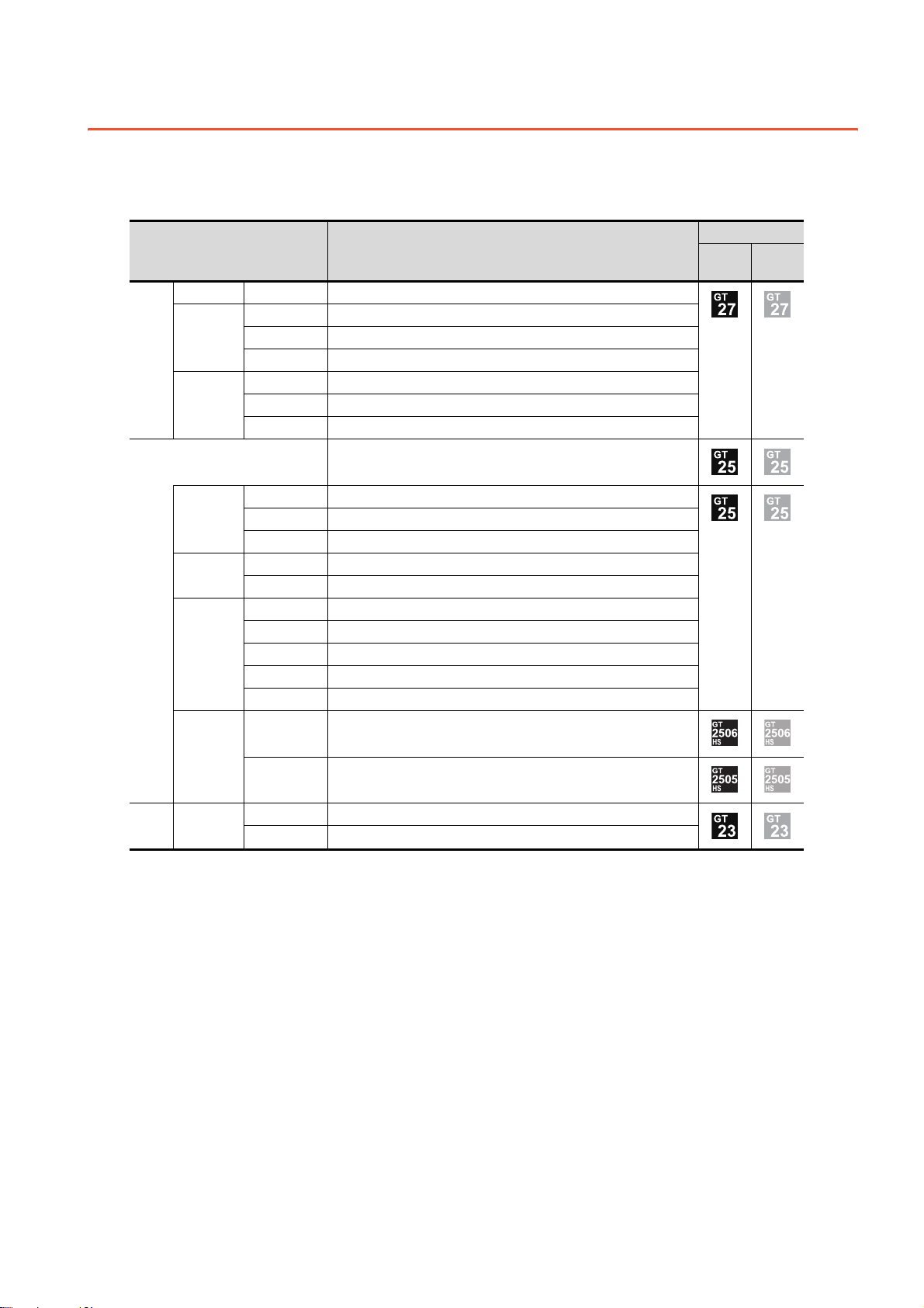
Abbreviations, Generic Terms, Model Icons
The following shows the abbreviations, generic terms, and model icons used in this manual.
■1. GOT
(1) GOT2000 series
Abbreviations and generic terms Description
GT27-X GT2715-X GT2715-XTBA, GT2715-XTBD
GT2712-S GT2712-STBA, GT2712-STWA, GT2712-STBD, GT2712-STWD
GT27-S
GT27
GT27-V
GT25-W
GT25-S
GT25
GT25-V
GT2710-S GT2710-STBA, GT2710-STBD
GT2708-S GT2708-STBA, GT2708-STBD
GT2710-V GT2710-VTBA, GT2710-VTWA, GT2710-VTBD, GT2710-VTWD
GT2708-V GT2708-VTBA, GT2708-VTBD
GT2705-V GT2705-VTBD
All GT25 models
GT2510-WX GT2510-WXTBD, GT2510-WXTSD
GT2507-W GT2507-WTBD, GT2507-WTSD
GT2507T-W GT2507T-WTSD
GT2512-S GT2512-STBA, GT2512-STBD
GT2512F-S GT2512F-STNA, GT2512F-STND
GT2510-V GT2510-VTBA, GT2510-VTWA, GT2510-VTBD, GT2510-VTWD
GT2510F-V GT2510F-VTNA, GT2510F-VTND
GT2508-V GT2508-VTBA, GT2508-VTWA, GT2508-VTBD, GT2508-VTWD
GT2508F-V GT2508F-VTNA, GT2508F-VTND
GT2505-V GT2505-VTBD
Meaning of icon
Support
support
Not
GT25HS-V
Handy GOT
GT23 GT23-V
GT2506HS-V GT2506HS-VTBD
GT2505HS-V GT2505HS-VTBD
GT2310-V GT2310-VTBA, GT2310-VTBD
GT2308-V GT2308-VTBA, GT2308-VTBD
A - 25
Page 28
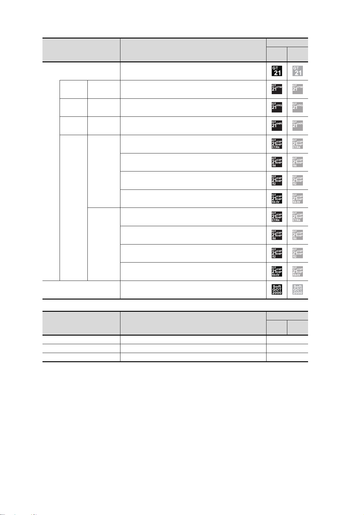
Abbreviations and generic terms Description
All GT21 models
GT21-W GT2107-W GT2107-WTBD, GT2107-WTSD
GT21-Q GT2105-Q GT2105-QTBDS, GT2105-QMBDS
GT21-R GT2104-R GT2104-RTBD
GT2104-PMBD
GT2104-PMBDS
GT21
GT21-P
GT2104-P
GT2104-PMBDS2
GT2104-PMBLS
GT2103-PMBD
Meaning of icon
Support
support
Not
GT2103-PMBDS
GT2103-P
GT2103-PMBDS2
GT2103-PMBLS
GT SoftGOT2000 GT SoftGOT2000 Version1
(2) GOT1000 series, GOT900 series, and GOT800 series
Abbreviations and generic terms Description
GOT1000 Series GOT1000 Series -
GOT900 Series GOT-A900 Series, GOT-F900 Series -
GOT800 Series GOT-800 Series -
Meaning of icon
Support
support
Not
A - 26
Page 29

■2. Communication unit
Abbreviations and generic terms Description
Bus connection unit
Serial communication unit GT15-RS2-9P, GT15-RS4-9S, GT15-RS4-TE
MELSECNET/H communication unit GT15-J71LP23-25, GT15-J71BR13
CC-Link IE Controller Network communication unit GT15-J71GP23-SX
CC-Link IE Field Network communication unit GT15-J71GF13-T2
CC-Link communication unit GT15-J61BT13
Wireless LAN communication unit GT25-WLAN
Serial multi-drop connection unit GT01-RS4-M
Connection conversion adapter GT10-9PT5S
Field network adapter unit GT25-FNADP
Ethernet communication unit GT25-J71E71-100
RS-232/485 signal conversion adapter GT14-RS2T4-9P
■3. Option unit
Abbreviations and generic terms Description
Printer unit GT15-PRN
Video input unit GT27-V4-Z (A set of GT16M-V4-Z and GT27-IF1000)
Video/RGB unit
Multimedia unit GT27-MMR-Z (A set of GT16M-MMR-Z and GT27-IF1000)
Video signal conversion unit GT27-IF1000
External I/O unit GT15-DIO, GT15-DIOR
Sound output unit GT15-SOUT
SD card unit GT21-03SDCD
RGB input unit GT27-R2, GT27-R2-Z (A set of GT16M-R2-Z and GT27-IF1000)
Video/RGB input unit GT27-V4R1-Z (A set of GT16M-V4R1-Z and GT27-IF1000)
RGB output unit GT27-ROUT, GT27-ROUT-Z (A set of GT16M-ROUT-Z and GT27-IF1000)
GT15-QBUS, GT15-QBUS2, GT15-ABUS, GT15-ABUS2, GT15-75QBUSL,
GT15-75QBUS2L, GT15-75ABUSL, GT15-75ABUS2L
■4. Option
SD card
Battery GT11-50BAT, GT15-BAT
Protective sheet
Environmental protection sheet GT25F-12ESGS, GT25F-10ESGS, GT25F-08ESGS
Protective cover for oil
USB environmental protection cover GT25-UCOV, GT25-05UCOV, GT21-WUCOV
Stand
Abbreviations and generic terms Description
NZ1MEM-2GBSD, NZ1MEM-4GBSD, NZ1MEM-8GBSD, NZ1MEM-16GBSD,
L1MEM-2GBSD, L1MEM-4GBSD
GT27-15PSGC, GT25-12PSGC, GT25-10WPSGC, GT25-10PSGC, GT2508PSGC, GT21-07WPSGC, GT25T-07WPSVC, GT25-05PSGC, GT2505PSGC-2, GT21-05PSGC, GT21-04RPSGC-UC, GT21-03PSGC-UC,
GT21-04PSGC-UC, GT27-15PSCC, GT25-12PSCC, GT25-10WPSCC,
GT25-10PSCC, GT25-08PSCC, GT25-05PSCC, GT25-05PSCC-2, GT2512PSCC-UC, GT25-10PSCC-UC, GT25-08PSCC-UC, GT21-07WPSCC,
GT21-05PSCC, GT21-04RPSCC-UC, GT21-04PSCC-UC, GT21-03PSCCUC, GT16H-60PSC, GT14H-50PSC
GT20-15PCO, GT20-12PCO, GT20-10PCO, GT20-08PCO, GT25T07WPCO, GT25-05PCO, GT05-50PCO, GT21-04RPCO, GT10-30PCO,
GT10-20PCO
GT15-90STAND, GT15-80STAND, GT15-70STAND, GT05-50STAND, GT2510WSTAND, GT21-07WSTAND, GT25T-07WSTAND
A - 27
Page 30

Abbreviations and generic terms Description
Attachment
Panel-mounted USB port extension GT14-C10EXUSB-4S, GT10-C10EXUSB-5S
Connector conversion box GT16H-CNB-42S, GT16H-CNB-37S, GT11H-CNB-37S
Emergency stop switch guard cover GT16H-60ESCOV, GT14H-50ESCOV
Wall-mounting attachment GT14H-50ATT
■5. Software
(1) Software related to GOT
Abbreviations and generic terms Description
GT Works3 SW1DND-GTWK3-J, SW1DND-GTWK3-E, SW1DND-GTWK3-C
GT Designer3 Version1 Screen design software GT Designer3 for GOT2000/GOT1000 series
GT Designer3
GT Designer3 (GOT2000)
GT Designer3 (GOT1000) Screen design software for GOT1000 series included in GT Works3
Speech synthesis license GT Works Text to Speech License (SW1DND-GTVO-M)
GT Simulator3 Screen simulator GT Simulator3 for GOT2000/GOT1000/GOT900 series
GT SoftGOT2000 Monitoring software GT SoftGOT2000
GT Converter2 Data conversion software GT Converter2 for GOT1000/GOT900 series
GT Designer2 Classic Screen design software GT Designer2 Classic for GOT900 series
GT Designer2 Screen design software GT Designer2 for GOT1000/GOT900 series
DU/WIN Screen design software FX-PCS-DU/WIN for GOT-F900 series
GT15-70ATT-98, GT15-70ATT-87, GT15-60ATT-97, GT15-60ATT-96, GT1560ATT-87, GT15-60ATT-77, GT21-04RATT-40
Screen design software for GOT2000 series included in GT Works3
(2) Software related to iQ Works
Abbreviations and generic terms Description
iQ Works
MELSOFT Navigator
MELSOFT iQ AppPortal
Abbreviation of iQ Platform compatible engineering environment MELSOFT
iQ Works
Generic term for integrated development environment software included in the
SW DNC-IQWK (iQ Platform compatible engineering environment MELSOFT
iQ Works)
(□ indicates a version.)
SW□DND-IQAPL-M type integrated application anagement software
(□ indicates a version.)
A - 28
Page 31

(3) Other software
Abbreviations and generic terms Description
GX Works3
GX Works2
GX Simulator3 Simulation function of GX Works3
GX Simulator2 Simulation function of GX Works2
Controller simulator
GX Simulator
GX Developer
GX LogViewer
MI Configurator
PX Developer
MT Works2
MT Developer
CW Configurator
MR Configurator2
MR Configurator
FR Configurator
NC Configurator2 CNC parameter setting support tool (FCSB1221)
NC Configurator CNC parameter setting support tool
FX Configurator-FP
FX3U-ENET-L Configuration tool FX3U-ENET-L type Ethernet module setting software (SW1D5-FXENETL-E)
RT ToolBox2 Robot program creation software (3D-11C-WINE)
RT ToolBox3 Robot program creation software (3F-14C-WINE)
MX Component
MX Sheet
CPU Module Logging Configuration Tool CPU module logging configuration tool (SW1DNN-LLUTL-E)
SW□DND-GXW3-E (-EA) type programmable controller engineering software
(□ indicates a version.)
SW□DNC-GXW2-□ type programmable controller engineering software
(□ indicates a version.)
SW□D5C-LLT-E (-EV) type ladder logic test tool function software package
(SW5D5C-LLT (-V) or later versions)
(□ indicates a version.)
SW□D5C-GPPW-E (-EV)/SW□D5F-GPPW (-V) type software package
(□ indicates a version.)
SW□DNN-VIEWER-E type software package
(□ indicates a version.)
Configuration and monitor tool for Mitsubishi Electric industrial computers (SW
□ DNNMICONF-M)
(□ indicates a version.)
SW□D5C-FBDQ-E type FBD software package for process control
(□ indicates a version.)
Motion controller engineering environment MELSOFT MT Works2(SW□DNDMTW2-E)
(□ indicates a version.)
SW□RNC-GSV type integrated start-up support software for motion controller
Q series
(□ indicates a version.)
C Controller module configuration and monitor tool (SW1DND-RCCPU-E)
(□ indicates a version.)
SW□DNC-MRC2-E type servo configuration software
(□ indicates a version.)
MRZJW□-SETUP type servo configuration software
(□ indicates a version.)
Inverter setup software (FR-SW□-SETUP-WE)
(□ indicates a version.)
Parameter setting, monitoring, and testing software packages for FX3U20SSC-H (SW□D5CFXSSCE)
(□ indicates a version.)
MX Component Version□(SW□D5C-ACT-E, SW□D5C-ACT-EA)
(□ indicates a version.)
MX Sheet Version□(SW□D5C-SHEET-E, SW□D5C-SHEET-EA)
(□ indicates a version.)
■6. License key (for GT SoftGOT2000)
Abbreviations and generic terms Description
License key GT27-SGTKEY-U
A - 29
Page 32

■7. Others
IAI IAI Corporation
AZBIL Azbil Corporation
OMRON OMRON Corporation
KEYENCE KEYENCE CORPORATION
KOYO EI KOYO ELECTRONICS INDUSTRIES CO., LTD.
JTEKT JTEKT Corporation
SHARP Sharp Corporation
SHINKO Shinko Technos Co., Ltd.
CHINO CHINO CORPORATION
TOSHIBA TOSHIBA CORPORATION
TOSHIBA MACHINE TOSHIBA MACHINE CO., LTD.
PANASONIC Panasonic Corporation
PANASONIC IDS Panasonic Industrial Devices SUNX Co., Ltd.
HITACHI IES Hitachi Industrial Equipment Systems Co., Ltd.
HITACHI Hitachi, Ltd.
HIRATA Hirata Corporation.
FUJI FUJI ELECTRIC CO., LTD.
MURATEC Muratec products manufactured by Murata Machinery, Ltd.
YASKAWA YASKAWA Electric Corporation
YOKOGAWA Yokogawa Electric Corporation
RKC RKC INSTRUMENT INC.
ALLEN-BRADLEY Allen-Bradley products manufactured by Rockwell Automation, Inc.
CLPA CC-Link Partner Association
GE GE Intelligent Platforms, Inc.
HMS HMS Industrial Networks
LS IS LS Industrial Systems Co., Ltd.
MITSUBISHI ELECTRIC INDIA Mitsubishi Electric India Pvt. Ltd.
ODVA Open DeviceNet Vendor Association, Inc.
SCHNEIDER Schneider Electric SA
SICK SICK AG
SIEMENS Siemens AG
PLC Programmable controller manufactured by each corporation
Control equipment Control equipment manufactured by each corporation
Temperature controller Temperature controller manufactured by each corporation
Indicating controller Indicating controller manufactured by each corporation
Controller Controller manufactured by each corporation
Abbreviations and generic terms Description
A - 30
Page 33

PART 1
PART 1UTILITY FOR GT27/GT25/GT23
1. UTILITY FUNCTION . . . . . . . . . . . . . . . . . . . . . . . . . . . . . . 1 - 1
2. GOT BASIC SETTING. . . . . . . . . . . . . . . . . . . . . . . . . . . . . 2 - 1
3. EXTENDED FUNCTION SETTING . . . . . . . . . . . . . . . . . . . 3 - 1
4. MAINTENANCE. . . . . . . . . . . . . . . . . . . . . . . . . . . . . . . . . . 4 - 1
5. MONITOR . . . . . . . . . . . . . . . . . . . . . . . . . . . . . . . . . . . . . . 5 - 1
6. DATA CONTROL . . . . . . . . . . . . . . . . . . . . . . . . . . . . . . . . . 6 - 1
7. INSTALLATION OF BOOTOS AND BASIC SYSTEM
APPLICATION . . . . . . . . . . . . . . . . . . . . . . . . . . . . . . . . . . . 7 - 1
8. SYSTEM ALARM DISPLAY AND LIST. . . . . . . . . . . . . . . . 8 - 1
Page 34

Page 35

1. UTILITY FUNCTION
• Install directly from GT Designer3
Via a USB interface or
RS-232 interface or
Ethernet interface
GT Designer3
GT Designer3
Writing system applications
to a file
2) GT Designer3 → Data storage → GOT
GOT
GOT
GOT
GOT
*1
*1
*1
Installing BootOS or
basic system application
Installing BootOS or
basic system application
• When GOT is remote,
install using a data storage easily
Install a data
storage to
the GOT
Install a data
storage to
the GOT
Data storage
Data storage
• Install from the GOT to the GOT
using a data storage
Uploading system
application files
1) GT Designer3→GOT
3) GOT → Data storage → GOT
Utility is a function, which carries out connection of GOT and controller, screen display and operation method settings,
program/data control and self-check etc.
Refer to the following for the utility function list.
➠ 1.2 Utility Function List
1.1 Utility Execution
For utility execution, utility has to be displayed by installing BootOS and basic system application in the C drive (built in flash
memory).
There are following three types for the installing BootOS and basic system application methods.
1
UTILITY FUNCTION
Refer to the following for the installation which uses GT Designer3.
Refer to the following for the installation which uses GOT.
*1 When installing the BootOS and basic system application, standard monitor OS has to be installed in GOT in advance.
➠ GT Designer3 (GOT2000) Screen Design Manual
➠ 7. INSTALLATION OF BOOTOS AND BASIC SYSTEM APPLICATION
1.1 Utility Execution
1 - 1
Page 36

1.2 Utility Function List
The items in the following list can be set/operated on the utility screens.
For GT Designer3 of an old version, displayed screens, setting items and others may differ from those described in the
manual.
The sequence program monitor (R ladder) will be supported soon.
Applicable GOT
GT27 GT25 GT23
*8
GOT basic
setting
Item Functions overview
Setting the startup screen display time and
screen saving time
Setting the battery alarm display to ON or OFF
Display
Language Switching message languages 2.2
Unique information Setting the GOT ID number 2.3
IP address
IP filter setting
Operation
Utility call key Setting the utility call keys 2.7
USB host Setting the USB mouse/keyboard
Setting the detect level/detect time of human
sensor
Adjusting brightness
Setting the GOT IP address, subnet mask, and
default gateway
Setting the GOT operation when a device with
the same IP address as that of the GOT is
added to the network afterwards.
Setting IP addresses from which access to the
GOT is allowed or blocked
Setting the buzzer volume and window move
buzzer
Setting a musical interval for the buzzer
sound*4
Setting the key sensitivity and key reaction
speed
Setting the access switch for the drive A
Reference
2.1
2.4
2.5
2.6
2.8
Time Displaying and setting the clock current time 2.9
Assign Ethernet I/F Setting the assign Ethernet I/F
Channel - Driver assign
Changing
assignment
Controller
5 V power supply Setting 5 V power supply for channel No. 1
Communication detail setting
Ethernet communication
Transparent mode
GOT internal device monitor
Security Security level authentication Authenticating security levels 2.14
Displaying the communication driver assigned
to each channel
Changing the assigned communication driver
Setting communication parameters, setting or
deleting sequence program protection key
words, canceling sequence program
protection status
(When connecting to FX series CPU)
Displaying the contents of Ethernet setting,
changing the host
Setting the channel No. to be used for the
communication for the FA transparent function
Setting whether to use the GOT internal
device monitor of the GOT diagnostics
function
2.10
2.11
2.12
2.13
1 - 2
1.2 Utility Function List
Page 37

Maintenance
Item Functions overview
Operator management Managing operator
Operator
authentication
Function setting Setting the operator authentication function
SoftGOT-GOT link function Setting the SoftGOT-GOT link function 3.1
VNC server function Setting the VNC server function 3.2
Applicable GOT
GT27 GT25 GT23
Reference
2.15Password change Changing a password
1
Extended
function setting
Sequence program monitor Starting the sequence program monitor 3.3
Backup/restoration setting Setting the backup and restoration 3.4
Trigger backup setting Setting the trigger backup
Trigger
time
setting
License management
Video/RGB
Multimedia
Wireless LAN connection function Setting the wireless LAN connection function
System launcher
iQSS utility
ANDON connection
Batch self check
Setting the trigger time
Displaying the screen for registering and
releasing the license
Displaying the screen for setting the video/
RGB I/O unit
Displaying the screen for setting the
multimedia
Configuring a setting to enable the online
module change in the system launcher
function
Setting a drive for a data storage containing
the profile data of iQSS-compatible equipment
Setting the IP address of a client targeted for
the ANDON connection
Executing various diagnostics collectively and
copying the result to a data storage
*3
*3
*7
3.5
3.6
3.7
3.8
3.9
3.10
3.11
3.12
4.1
UTILITY FUNCTION
Maintenance
USB device management Displaying the status of USB device 4.2
Cleaning Displaying the screen for cleaning the display 4.3
Touch panel calibration Adjusting the touch panel 4.4
System alarm Displaying the system alarm 4.5
Drawing check Checking the drawing 4.6
Font check Checking the font 4.7
Touch panel check Checking the touch panel 4.8
I/O check Checking the I/O of RS-232 interface 4.9
Ethernet status check Checking the connection status of Ethernet 4.10
GOT information Displaying the GOT information 4.11
GOT Mobile information Displaying the GOT Mobile function settings 4.12
1.2 Utility Function List
1 - 3
Page 38

Item Functions overview
System launcher Starting the system launcher
Device monitor Starting the device monitor
Applicable GOT
GT27 GT25 GT23
Reference
Monitor
Sequence program monitor (Ladder)
Starting the QCPU or LCPU sequence
program monitor
Sequence program monitor (iQ-R ladder) Starting the RCPU sequence program monitor
FX ladder monitor Starting the FX ladder monitor
Network monitor Starting the network monitor
Intelligent module monitor Starting the intelligent module monitor
Servo amplifier monitor Starting the servo amplifier monitor
Q motion monitor Starting the Q motion monitor
R motion monitor Starting the R motion monitor
CNC monitor Starting the CNC monitor
CNC monitor 2 Starting the CNC monitor 2
Sequence program monitor (SFC) Starting the SFC monitor
Motion SFC monitor Starting the motion SFC monitor
Log viewer Starting the log viewer
Network status display Starting the network status display
*1 *2
*6
5.1
FX list editor Starting the FX list editor
CNC machining program edit Starting the CNC machining program edit
CNC data I/O Starting the CNC data I/O
Motion Program Editor Starting the motion program editor
Motion Program I/O Starting the motion program I/O
MELSEC-L troubleshooting Starting the MELSEC-L troubleshooting
iQSS utility Starting the iQSS utility
Drive recorder Starting the drive recorder
CC-Link IE Field Network diagnostics
Starting the CC-Link IE Field Network
diagnostics
Servo amplifier graph Starting the servo amplifier graph
*1 *2
*1
*1
*1
*5
*2
*2
*2
1 - 4
1.2 Utility Function List
Page 39

Data
management
Item Functions overview
Deleting or copying alarm log files
Alarm information
Image file management
Recipe information
Logging information
Operation log information
File manager
Package data management
Converting alarm log files in G2A format →
CSV/TXT format
Deleting/copying image files, changing image
file names
Converting recipe files in G2P → CSV/TXT
format, deleting/copying/moving/creating
recipe files, deleting/moving/changing recipe
folder names, writing/reading/verifying record
values with the recipe record list, deleting
device values
Converting logging files in G2L format → CSV/
TXT format
Deleting/copying/moving logging files,
changing logging file names
Converting operation log files in G20 → CSV/
TXT format
Deleting, copying, moving, or renaming an
operation log file, deleting or creating an
operation log folder
Deleting, copying, moving or renaming a folder
or file, sorting the list of folders and files, or
creating a folder
Installing/uploading package data, checking
the property
Applicable GOT
GT27 GT25 GT23
Reference
6.2
6.3
6.4
6.5
6.6
6.7
6.8
1
UTILITY FUNCTION
Backup/restoration Starting the backup/restoration function 6.9
Confirming the SRAM user area usage,
SRAM management
Memory card format Formatting a data storage 6.11
Memory check
GOT data package acquisition
*1 Available to GT27-X and GT27-S.
*2 Only available to GT25-S.
*3 GT2705-V does not support.
*4 Not available to GT23.
*5 Not available to GT25-W.
*6 Not available to GT25-W, GT2505-V, and GT2505HS-V.
*7 Not available to GT2505-V and GT25HS-V.
*8 Not available to GT25HS-V.
backing up or restoring the data in the SRAM
user area, and initializing the SRAM user area
Write/read check of a data storage and built-in
flash memory
Copying the data stored in the GOT to an SD
card in a batch
6.10
6.12
6.13
1.2 Utility Function List
1 - 5
Page 40

1.3 Utility Display
1)
2)
To display each setting screen of the utility, the main menu has to be displayed first.
Even when the GOT is installed vertically, the utility screen appears horizontally.
In the utility main menu, message dialogs appear according to the vertical installation.
1) Main menu
The menu items that can be set at the GOT utility are displayed.
Touching a menu item in the main menu will display the setting screen or subsequent selection screen for the
item.
2) System message switch button
This button switches the language used for the utility or system alarms.
When touching the [Language] button, the Select Language screen is displayed.
Step 1. Touch the button of the language to be displayed.
Step 2. Touch the [OK] button to restart the GOT for the selected language to take effect in the utility.
To cancel the setting, touch the [Cancel] button to return to the main menu.
1 - 6
1.3 Utility Display
Page 41

POINT
POINT
POINT
When starting the GOT without selecting any language or the selected language and the
installed fonts are not matched
The following screen will be displayed.
Touching the button of a desired language restarts the GOT and the language is switched to the
selected one.
(1) Selectable languages
The system message switch button is displayed only for the selectable languages.
The selectable languages differ depending on the fonts installed in the GOT.
For the relation between the selectable languages and the fonts, refer to the following.
➠ GT Designer3 (GOT2000) Screen Design Manual
(2) System language switching using the device
The system language can be switched using the system language switching device set with
GT Designer3.
For the setting method of the system language switching device, refer to the following.
➠ GT Designer3 (GOT2000) Screen Design Manual
1
UTILITY FUNCTION
1.3 Utility Display
1 - 7
Page 42

1.3.1 Display operation of main menu
POINTPOINTPOINT
Turning on the power
supply of the GOT
GOT basic setting
GOT basic setting
Utility call key
Touch a top left corner.
The following three types of operation can display the main menu.
(Display the main menu after installing the basic system application from GT Designer3 to the GOT built in flash memory.)
■1. When project data is undownloaded
If the power supply of GOT turns ON, the main menu is displayed automatically after title display.
■2. When touching menu call key
If you touch the menu call key while user-created screen is displayed, the main menu is displayed.
The menu call key is set in the position on the GOT screen upper left corner at factory shipment.
The menu call key can be set by the GOT utility or GT Designer3.
For the setting method of the utility call key, refer to the following.
➠ 2.7.3 Utility call key setting operation
➠ GT Designer3 (GOT2000) Screen Design Manual
(1) Prohibited simultaneous 2-point presses
Do not touch 2 points or more on the GOT screen simultaneously. Touching 2 points or more
simultaneously may activate a part other than the touched point.
(2) When setting menu call key to 1-point
When having set [Pressing time] of the menu call key setting screen to other than "0 (s)",
keep pressing the touch panel for the period set to [Pressing time] or more before leaving the
finger from the touch panel.
For menu call key setting, refer to the following.
➠ 2.7.3 Utility call key setting operation
1 - 8
1.3 Utility Display
Page 43
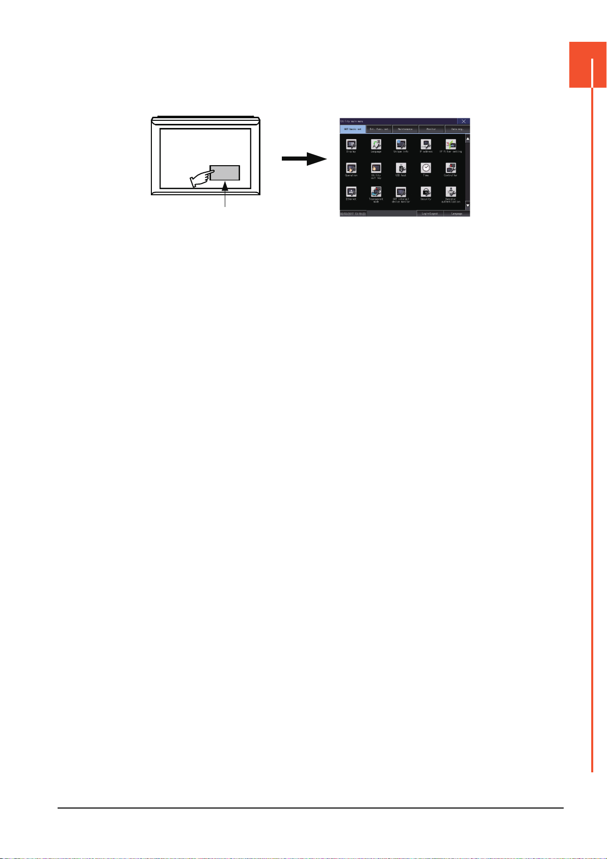
■3. When touching special function switch (utility)
GOT basic setting
Special function switch
(Utility)
If you touch the special function switch (utility) while user-created screen is displayed, the main menu is displayed.
The special function switch (utility) can be set as a touch switch that is displayed on a user-created screen by GT
Designer3.
For the details of the special function switch, refer to the following.
➠ GT Designer3 (GOT2000) Screen Design Manual
1
UTILITY FUNCTION
1.3 Utility Display
1 - 9
Page 44

POINTPOINTPOINT
Locking the utility display by password
When you try to display the utility main menu while the password is set to the GOT by GT
Designer3, the display for password input will be appeared.
(Set a password from the common setting menu.)
When the password is not matched, displays the error message.
When touching the [OK] button, the screen returns to the monitor screen.
(1) Input operation of password
Step 1. Input the password after touching [0] to [9], [A] to [F] key.
Step 2. Define the password by touching [Enter] key, after password input.
Step 3. To correct the input character, touch [Del] key to delete the correcting character
and reinput/retype the new character.
(2) Password input cancel operation
When the button is touched, it returns to the monitor screen.
Refer to the following for the details related to the password setting.
➠ GT Designer3 (GOT2000) Screen Design Manual
1 - 10
1.3 Utility Display
Page 45

1.3.2 Utility basic configuration
Title display Close/Return button
Scroll button
Screen
Title display
The basic configuration of utility is as follows.
■1. Title display
The screen title name is displayed in title display part.
As the screen is composed of multiple layers, the title including these layers is displayed.
1
UTILITY FUNCTION
■2. Close/Return button
When a middle screen of the layers is displayed, if the (Close/return) button in the right corner of screen is
touched, returns to the previous screen.
If this button is touched when directly displayed from monitor screen, the screen is closed and returns to monitor
screen.
■3. Scroll button
For screens in which the content does not fit on one screen page, there is a right or down scroll button on the screen.
/ / / Scroll one line/column.
/ / / Scroll window.
1.3 Utility Display
1 - 11
Page 46

1.3.3 Basic operation of settings change
Setting item
Select button
Close/Return button
Example: [Operation] screen
■1. Change of setting value
(1) Setting item, select button
Touch the select button to change the settings.
The setting methods differ depending on the setting items.
The following types of setting method are available.
(a) Switching the setting value
Touch the button to switch the setting value as shown in .
ON OFF
(b) Enter the setting value with a keyboard.
Touch the button to display a keyboard on the GOT screen.
(c) Move to another setting screen.
Touch the button to move to another setting screen.
For the setting method of each setting item, refer to the setting operation of each setting screen.
(2) [OK] button, [Cancel] button, (Close/Return) button
Reflect or cancel the changed settings.
• [OK] button
Touch this button to reflect the changed settings and return to the previous screen.
Depending on the setting item, the GOT restarts.
• [Cancel] button
Touch this button to cancel the changed settings and return to the previous screen.
• (Close/Return) button
Touching the button displays the following dialog. (If no setting is changed, the dialog is not displayed.)
Operate following the message of the dialog.
1 - 12
1.3 Utility Display
Page 47

2. GOT BASIC SETTING
Setting screen for display and setting screen for operation can be displayed from the GOT utility screen.
In the setting screen for display and the setting screen for operation, the following settings can be set.
Item Description Reference
Display
Language Language setting 2.2
Unique information Number setting, GOT name display, GOT description display 2.3
IP address
IP filter setting
Operation
Utility call key Call key setting, pressing time setting 2.7
USB host
Time setting Current time, GOT internal battery voltage status
Adjust
Time
Broadcast
Local time Specify time zone, time zone, time difference from GMT
Controller The setting contents of the communication interface can be checked or changed. 2.10
Ethernet communication The contents of the Ethernet setting can be checked and the host can be changed. 2.11
Transparent mode Channel No. setting 2.12
GOT internal device monitor Setting whether to use the GOT internal device monitor of the GOT diagnostics function 2.13
Security Security level authentication 2.14
Operator authentication Operator management, password change function setting 2.15
Opening screen time, screen save time, battery alarm display, human sensor, sensor detect level,
sensor detect time, sensor off delay, brightness adjustment mode, brightness adjustment, POWER LED
Ethernet communication unit, IP address, subnet mask, default gateway, peripheral software port No.,
transparent port No., behavior of duplicate IPs
IP filter usage, specification of filtering method, specifications of target IP address and exception IP
address
Buzzer sound, musical interval, window move buzzer volume, Key sensitivity, Access switch for the
drive A
USB mouse setting, interlock with mouse cursor touch operation, USB keyboard setting, USB keyboard
type setting
Adjust the clock, mode, reference CH No., SNTP IP address, trigger type, specify the time zone of
target unit, time zone, time difference from GMT
Broadcast the clock data, broadcast CH No., trigger type, specify the time zone of target unit, time zone,
time difference from GMT
2
2.1
2.4
2.5
2.6
GOT BASIC SETTING
2.8
2.9
2 - 1
Page 48

2.1 Display
2.1.1 Display setting
Configure display settings.
The items which can be set are shown below. When each item part is touched, the respective setting becomes possible.
Item Description Setting range
Opening screen time The title display period at the main unit boot can be set.
Screen save time
Battery alarm display
Human sensor
Sensor detect level
Sensor detect time
Sensor off delay
Brightness adjustment mode
Brightness adjustment The brightness can be adjusted.
POWER LED*5 Turning on/off the POWER LED can be set.
*2
*2
*3
The period from the user stops the touch panel operation till the
screen save function starts can be set.
Whether to display system alarm when the voltage of the GOT
internal battery has dropped can be specified.
Screen saver status cancel by human sensor can be set to Effective
or Invalid.
The sensor detect level can be set.
The time corresponding to the [Sensor detect level] is displayed.
(setting is disabled)
When the [Sensor detect level] is changed, the corresponding time is
reflected by touching [OK] button.
The time period from when the human sensor detects no human
movement until the Human Sensor Detection Signal (System Signal
2-1.b5) turns OFF can be set.
The brightness adjustment mode can be set to the standard or low
intensity mode.
0 to 60 seconds
<At factory shipment: 0 seconds>
0 to 60 minutes
<At factory shipment: 0 minutes>
ON/OFF
<At factory shipment: OFF>
Valid/Invalid
<At factory shipment: Invalid>
0 to 10
<At factory shipment: 10>
0 to 4
<At factory shipment: 0 seconds>
0Min 10Sec to 60Min 0Sec
<At factory shipment: 0Min 10Sec>
Standard/Low
<At factory shipment: standard>
1 to 32
<Default: 32>
Turn ing on/off
<At factory shipment: turning on>
*1
*1
*4
*1 If setting 0, the title screen is not hidden.
The title screen is always displayed for 4 seconds or longer (which changes depending on the project data contents).
*2 The monitoring time corresponding to the sensor detect level (0 to 10) is as follows.
As the sensor detect level becomes greater, the sensitivity of the human sensor becomes higher.
Sensor detect level 109876543210
Sensor detect time [s] 0 0.1 0.2 0.4 0.8 1 1.5 2 2.5 3 4
*3 For BootOS version D or earlier, the [Standard] mode is specified.
*4 For GT23, the brightness can be adjusted in 16 levels.
The following table shows the correspondences between values set in the utility and the brightness in 16 levels.
Setting value 12345678 ··· 2526272829303132
Brightness adjustment (16
levels)
*5 GT23 does not support.
1 2 3 4 ··· 13 14 15 16
2 - 2
2.1 Display
Page 49

POINT
POINT
ON
OFF
Operator motion
[Sensor detect level]
Human Sensor
Detection Signal
[System Signal 2-1.b5]
[Sensor detect time]
Approach Go away Approach Go away
[Sensor off delay]
Screen saver
Screen saving mode released
Screen saver
mode activated
[Screen save time]
[Sensor off delay]
POINT
(1) Display setting by GT Designer3
Set the title display period and screen save time in [GOT setup] in [Environmental Setting] of
GT Designer3.
When change a part of the setting, change the setting by the GOT display setting after
downloading the project data.
➠ GT Designer3 (GOT2000) Screen Design Manual
(2) Screen save time
Using the system information function can compulsorily switch the controller to the screen
saving status (Forced Screen Saver Disable Signal) or disable the screen save time
(Automatic Screen Saver Disable Signal) set with Utility.
➠ GT Designer3 (GOT2000) Screen Design Manual
(3) Display control by human sensor
The human sensor is a function that releases the GOT from the screen saving mode without
the necessity to touch the GOT.
This function releases the GOT from the screen saving mode when the operator has come
closer to the GOT.
2
GOT BASIC SETTING
When there is no operator around the GOT for the time set as "Sensor OFF delay", the "Human
Sensor Detection Signal" turns OFF.
When the time set as the "Screen save time" elapses after the "Human Sensor Detection Signal" turns
OFF, the GOT enters the screen saving mode.
Refer to the following for the Human Sensor Detection Signal (System Signal 2-1.b5).
➠ GT Designer3 (GOT2000) Screen Design Manual
(4) When setting the human sensor to invalid
Even if setting the human sensor to invalid by the utility, the Human Sensor Detection Signal
(System Signal 2-1.b5) turns ON when the human sensor detects human movement.
Unintended operation may result, therefore, if controlling the Forced Screen Saver Enable
Signal (System Signal 1-1.b1) and Human Sensor Detection Signal associating them with
each other by a sequence program, etc.
When setting the human sensor to invalid, review the related sequence program, etc.
(5) Restrictions on the backlight shutoff detection in the [Low] mode
In the [Low] mode, the GOT cannot detect the backlight shutoff.
To detect the backlight shutoff, set the brightness adjustment mode to [Standard].
(6) Restrictions on the screen display in the [Low] mode
In the [Low] mode, the screen may flicker, or the screen display may turn off.
If you do not use the GOT in a dark place, set the brightness adjustment mode to [Standard].
2.1 Display
2 - 3
Page 50

(7) When the utility screen is difficult to see in the [Low] mode
Display
Touch
[Display].
GOT basic setting
Touch the upper-left corner of the main menu for two seconds to change the mode to the
[Standard] mode.
When the utility screen transitions to a user-created screen, the mode is returned to the [Low]
mode.
2.1.2 Display operation of display
2 - 4
2.1 Display
Page 51

2.1.3 Display setting operations
■1. Opening screen, screen save time
Step 1. Touch the setting item (numeral) to display a software keyboard.
Input a value with the keyboard.
Step 2. Touch the [OK] button to restart the GOT and reflect the setting change.
To cancel the setting change and return to the Main Menu, touch the [Cancel] button.
■2. Battery alarm display
Step 1. Touch the setting item to change the selection. (ON OFF)
2
GOT BASIC SETTING
Step 2. Touch the [OK] button to restart the GOT and reflect the setting change.
To cancel the setting change and return to the Main Menu, touch the [Cancel] button.
2.1 Display
2 - 5
Page 52

■3. Human sensor
Step 1. Touch the setting item to change the selection. (Valid Invalid)
Step 2. Touch the [OK] button to restart the GOT and reflect the setting change.
To cancel the setting change and return to the Main Menu, touch the [Cancel] button.
■4. Sensor detect level, sensor off delay
Step 1. Touch the setting item (numeral) to display a software keyboard.
Input a value with the keyboard.
To move the cursor, touch the or button.
Step 2. Touch the [OK] button to restart the GOT and reflect the setting change.
To cancel the setting change and return to the Main Menu, touch the [Cancel] button.
2 - 6
2.1 Display
Page 53

■5. Brightness adjustment mode
Step 1. Touch the setting item to change the selection. (Standard Low)
Step 2. Touch the [OK] button to restart the GOT and reflect the setting change.
To cancel the setting change and return to the Main Menu, touch the [Cancel] button.
■6. Brightness adjustment
Step 1. Touch the [+] or [-] key to adjust the brightness.
2
GOT BASIC SETTING
Step 2. If touch the [OK] button, the changed settings are reflected and the screen returns to the [Display] screen.
If touch the [Cancel] button, the changed settings are canceled and the screen returns to the [Display]
screen.
2.1 Display
2 - 7
Page 54

■7. POWER LED
Step 1. Touch the setting item to change the selection. (ON OFF)
Step 2. Touch the [OK] button to restart the GOT and reflect the setting change.
To cancel the setting change and return to the Main Menu, touch the [Cancel] button.
2 - 8
2.1 Display
Page 55

2.2 Language
Language
GOT basic setting
Touch
[Language].
2.2.1 Language setting
Configure language settings.
Item Description Setting range
Confirmation of the current language and switching
language can be performed regarding with the language
displayed by utility and dialog.
Language
*1
*1 Only selectable languages are displayed.
The selectable languages differ depending on the fonts installed in the GOT.
For details of the fonts, refer to the following.
➠ GT Designer3 (GOT2000) Screen Design Manual
2.2.2 Display operation of language display
2
(Japanese)
(English)
(Chinese (Simplified))
(Chinese
(Traditional))
(Korean)
(At factory shipment: User's
selection>
GOT BASIC SETTING
2.2 Language
2 - 9
Page 56

2.2.3 Setting operation of language
POINTPOINTPOINT
■1. Language
Step 1. If touch the language to be displayed, the language is selected.
Step 2. If touch the [OK] button, the GOT restarts and operates with the changed settings.
If touch the [Cancel] button, the changed settings are canceled and the screen returns to the Main Menu.
(1) Selectable languages
The system message switch button is displayed only for the selectable languages.
The selectable languages differ depending on the fonts installed in the GOT.
For the relation between the selectable languages and the fonts, refer to the following.
➠ GT Designer3 (GOT2000) Screen Design Manual
(2) System language switching using the device
The system language can be switched using the system language switching device set with
GT Designer3.
For the setting method of the system language switching device, refer to the following.
➠ GT Designer3 (GOT2000) Screen Design Manual
2 - 10
2.2 Language
Page 57
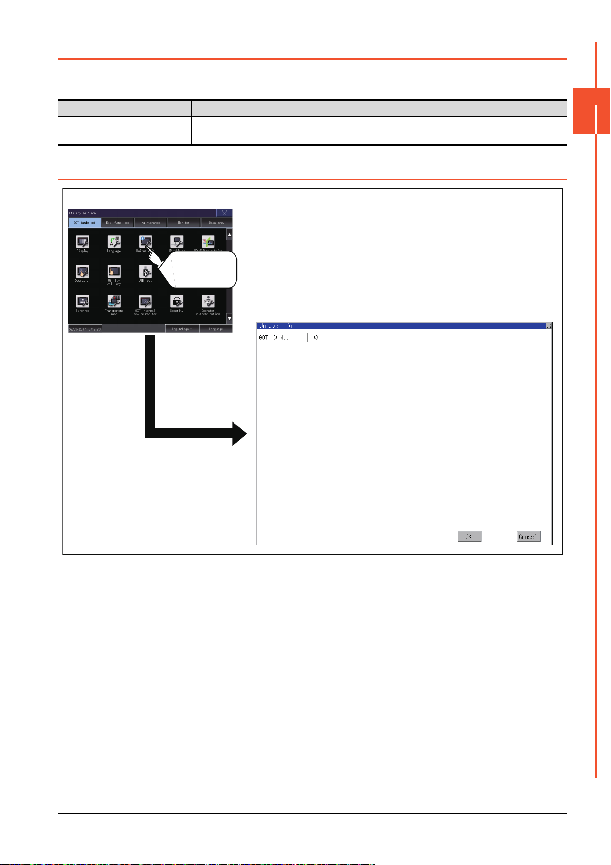
2.3 Unique Information
Unique information
GOT basic setting
Touch
[Unique info].
2.3.1 Unique information setting
Configure unique information settings.
Item Description Setting range
GOT ID No. Set the ID No. as the unique information for the GOT.
2.3.2 Display operation of unique information
2
0 to 32767
<Default: 0>
GOT BASIC SETTING
2.3 Unique Information
2 - 11
Page 58
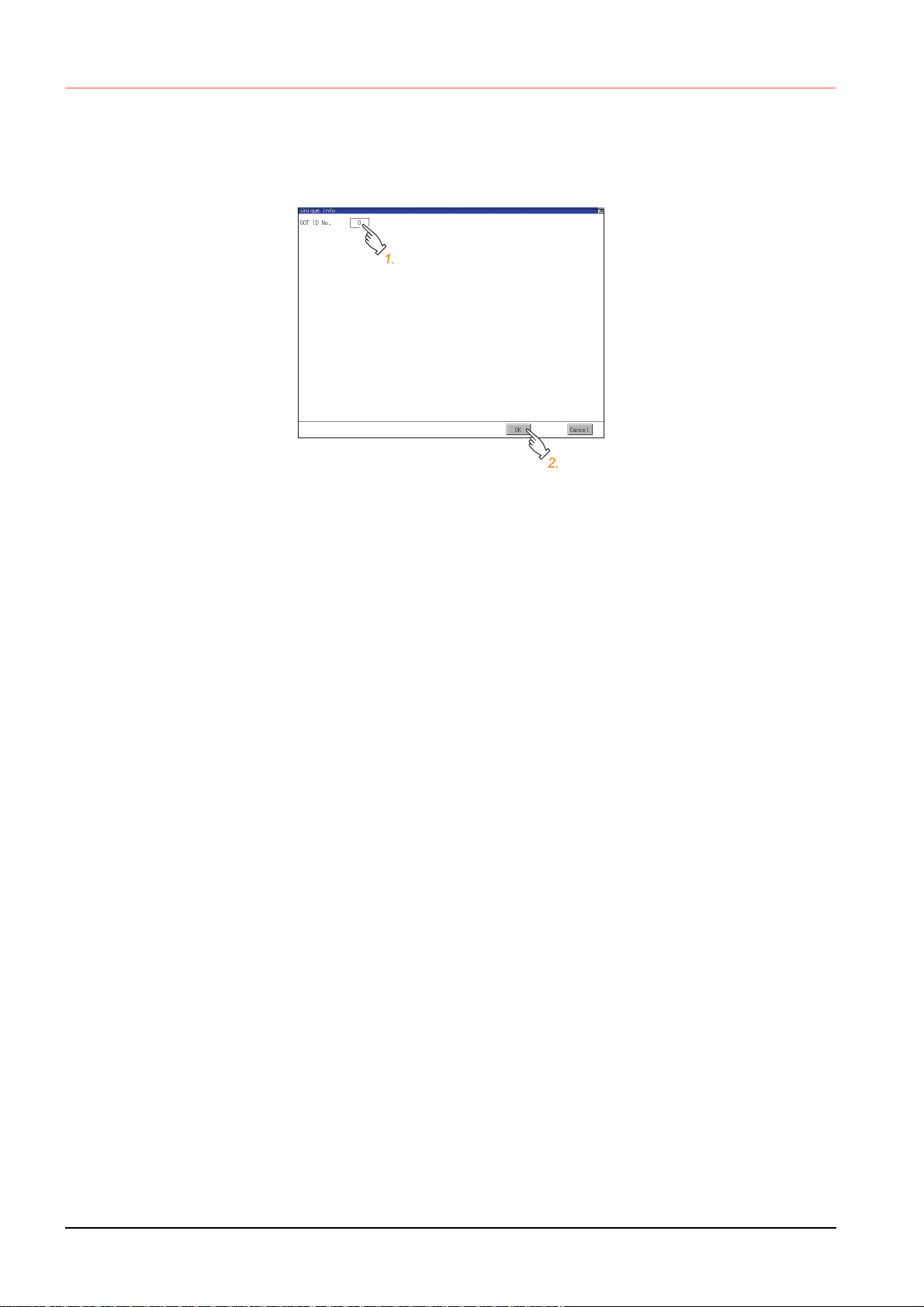
2.3.3 Setting procedure for unique information
■1. GOT ID No.
Step 1. Touch the setting item to display a software keyboard.
Input a value with the keyboard.
Step 2. Touch the [OK] button to restart the GOT and reflect the setting change.
To cancel the setting change and return to the Main Menu, touch the [Cancel] button.
2 - 12
2.3 Unique Information
Page 59
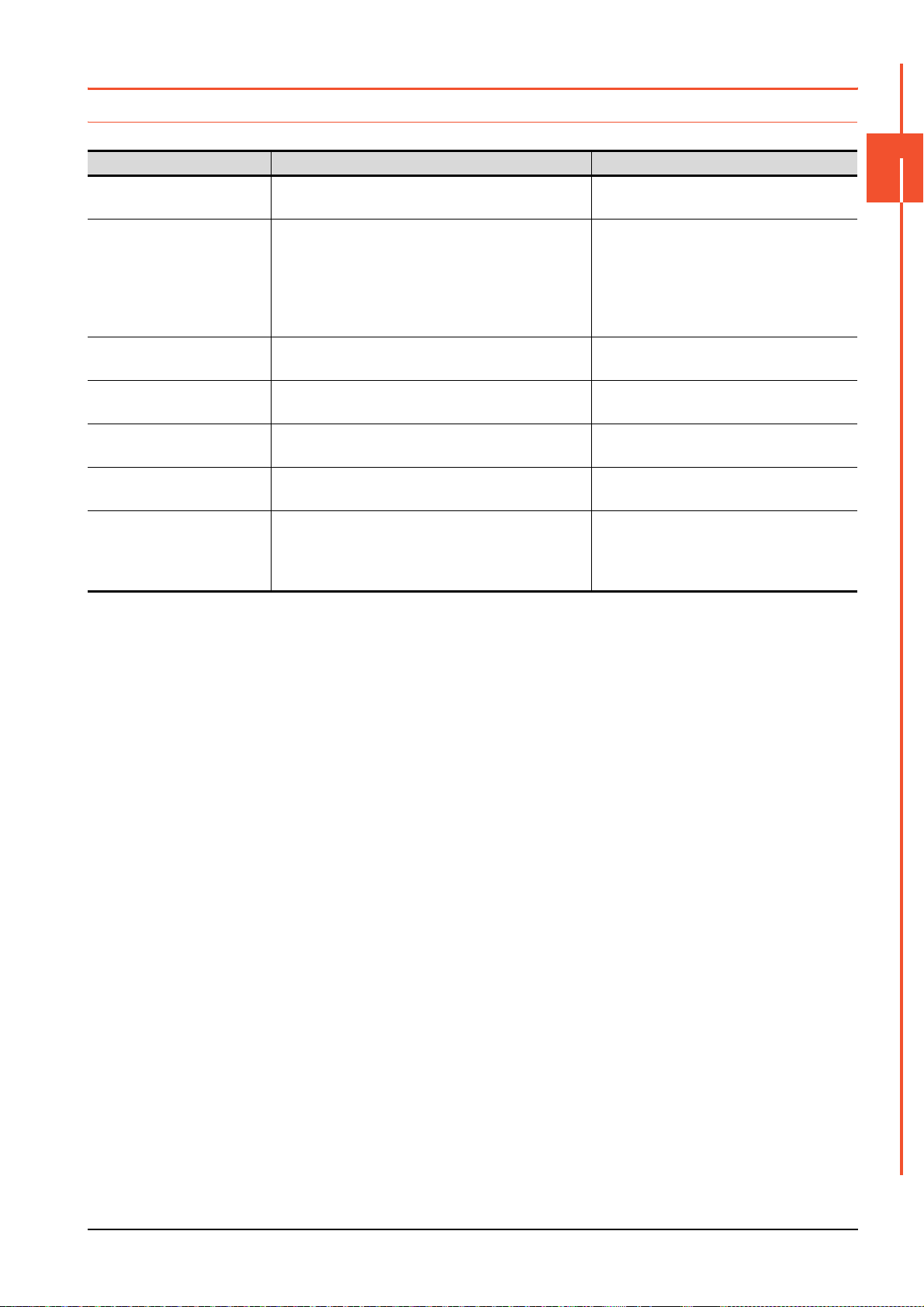
2.4 IP Address
2.4.1 IP address setting
Set the IP address and others.
Item Description Setting range
Ethernet comm. unit Set whether to use the Ethernet communication unit.
IP Address Check or set the IP address.
Subnet Mask Check or set the subnet mask.
Default Gateway Check or set the router address of the default gateway.
Per. S/W wireless port No.
Transparent port No.
Behavior of duplicate IPs
Set the port number for the GOT to use peripheral
software.
Set the port number for the GOT to use the FA
transparent function.
Set the behavior of the GOT to be performed when a
device with the same IP address as the GOT is
connected to the network afterwards.
Effective/Invalid
<Default: Invalid>
0.0.0.0 to 255.255.255.255
• Ethernet standard port, Ethernet standard
port 1 <Default: 192.168.3.18>
• Ethernet extension port, Ethernet standard
port 2 <Default: 192.168.5.22>
• Wireless LAN I/F <Default: 192.168.4.20>
0.0.0.0 to 255.255.255.255
<Default: 255.255.255.0>
0.0.0.0 to 255.255.255.255
<Default: 0.0.0.0>
1024 to 5010, 5014 to 49152, 49171 to 65534
<Default: 5014>
1024 to 5010, 5014 to 49152, 49171 to 65534
<Default: 5015>
Maintain a network connection (rec)/Do not
maintain a network connection
<Default: Maintain a network connection
(rec)>
2
GOT BASIC SETTING
2.4 IP Address
2 - 13
Page 60

2.4.2 Display operation of IP address
IP address(For GT27)
GOT basic setting
Touch
[IP address].
If the Ethernet setting is changed with applicable GOT special registers (GS), the GOT may not operate with the new
Ethernet setting displayed in the utility.
Therefore, restart the GOT to reflect the new setting.
2 - 14
2.4 IP Address
Page 61

2.4.3 Setting procedure for the IP address
POINTPOINTPOINT
■1. Ethernet standard port, Ethernet standard port 1, and wireless LAN I/F
(1) IP address, subnet mask, default gateway, peripheral software port No., and transparent port No.
Step 1.
Touch the entry box for the setting item to display a software keyboard.
Input a value with the keyboard.
Example) For GT27
Step 2. Touch the [OK] button to restart the GOT and reflect the setting.
To cancel the setting, touch the [Cancel] button to return to the main menu.
2
GOT BASIC SETTING
Settings of [Per. S/W port No.] and [Transparent port No.]
You cannot set the same port number for [Per. S/W port No.] and [Transparent port No.].
Set a different port number for each setting item.
(2) Behavior of duplicate IPs
This item is settable in the [Ethernet standard port] tab or the [Ethernet standard port 1] tab.
Step 1. Touch the selection for the setting item to switch the selection.
This setting determines the behavior of the GOT when a device with the same IP address connects to the
network on which the GOT resides.
• [Maintain a network connection (rec)]
Displays a system alarm, and maintains the network connection for the GOT.
• [Do not maintain a network connection]
Disconnects the GOT from the network.
Example) For GT27
2.4 IP Address
2 - 15
Page 62
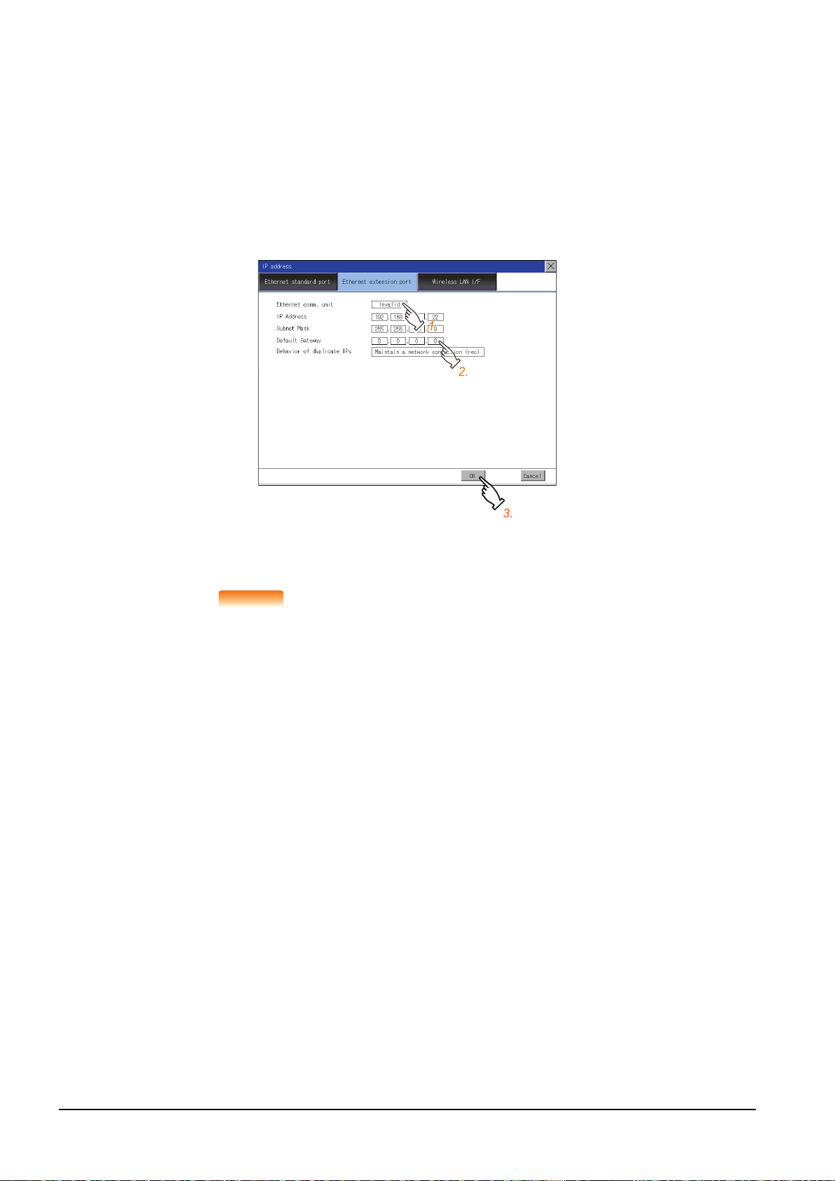
Step 2. Touch the [OK] button to restart the GOT and reflect the setting.
POINTPOINTPOINT
To cancel the setting, touch the [Cancel] button to return to the main menu.
■2. Ethernet extension port and Ethernet standard port 2
(1) IP address, subnet mask, default gateway, peripheral software port No., and transparent port No.
Step 1.
Touch the selection for [Ethernet comm. unit] to switch to [Effective].
Step 2. Touch the entry box for the setting item to display a software keyboard.
Input a value with the keyboard.
Example) For GT27
Step 3. Touch the [OK] button to restart the GOT and reflect the setting.
To cancel the setting, touch the [Cancel] button to return to the main menu.
Assignment to an extension interface
The Ethernet extension port is assigned to an unused extension interface with the lowest stage
number.
If all extension interfaces are occupied, the Ethernet extension port cannot be assigned.
2 - 16
2.4 IP Address
Page 63
(2) Behavior of duplicate IPs
This item is settable in [Ethernet standard port] or [Ethernet standard port 1].
Step 1. Touch the selection for the setting item to switch the selection.
This setting determines the behavior of the GOT when a device with the same IP address connects to the
network on which the GOT resides.
• [Maintain a network connection (rec)]
Displays a system alarm, and maintains the network connection for the GOT.
• [Do not maintain a network connection]
Disconnects the GOT from the network.
Example) For GT27
2
GOT BASIC SETTING
Step 2. Touch the [OK] button to restart the GOT and reflect the setting.
To cancel the setting, touch the [Cancel] button to return to the main menu.
2.4 IP Address
2 - 17
Page 64

2.4.4 Precautions
[Ethernet port1]: [Ethernet standard port] tab
[Ethernet port2]: [Ethernet extension port] tab
■1. IP address setting
Set an IP address for each interface to access a different network.
■2. When the GOT connects to the network on which a device with the same IP address
resides
The GOT goes into an offline state, and displays the following dialog.
Example) For GT27
Change the IP address of the GOT or the device.
• When changing the IP address of the device
Specify a new IP address for the device, and touch the [Reboot GOT] button to restart the GOT.
• When changing the IP address of the GOT
Touch the [Clear IP Address] button to clear the GOT IP address.
Then, touch the [Reboot GOT] button to restart the GOT, and specify a new IP address for the GOT.
■3. Selection for [Behavior of duplicate IPs]
When [Do not maintain a network connection] is selected for [Behavior of duplicate IPs], if a device with the same IP
address as the GOT connects to the same network, the GOT becomes disconnected from the network.
Thus, incorrect setting of IP addresses or any malicious action may disable the relevant GOT to communicate,
affecting the system control.
Make sure to consider the necessity to change the selection for [Behavior of duplicate IPs] before doing so.
■4. Using a switching hub compatible with the Spanning Tree Protocol
For the switching hub port connected with the GOT, configure the setting (PortFast or others) that makes the GOT be
ready for communications (forwarding state). Thus, the Spanning Tree Protocol does not cause a delay upon
connection.
Without the setting, the Ethernet IP address duplication is detected incorrectly.
Additionally, the GOT may not connect to the Ethernet network correctly.
For the setting that makes the GOT be ready for communications (forwarding state), refer to the user’s manual for the
switching hub used.
2 - 18
2.4 IP Address
Page 65
2.5 IP Filter Setting
2.5.1 IP filter setting
IP addresses from which access to the GOT is allowed or blocked can be set.
For the details of the IP filter setting, refer to the following.
➠ GT Designer3 (GOT2000) Screen Design Manual
Item Description Setting range
IP filter usage You can set whether to use or not the IP filter function.
You can set whether to allow or block access from the IP addresses that set
in the filtering list.
• If [Transmit] is selected
Access from the IP addresses that are set for [Target IP address] is
blocked.
Access from the following address
Range
Target IP address
Exception IP address
Access from the IP addresses that are set for [Exception IP address] is
disallowed.
• If [Block] is selected
Access from the IP addresses that are set for [Target IP address] is
blocked.
Access from the IP addresses that are set for [Exception IP address] is
allowed.
You can set whether to register IP addresses by specifying a range.
To specify a range, set the start IP address and the end IP address for
[Target IP address].
You can set IP addresses or IP address ranges to be filtered.
Up to 32 ranges can be set.
This item can be set only when [Range] is selected.
For an IP address range specified in [Target IP address], set IP addresses
excluded from being filtered.
Up to 32 addresses can be set for one range specified in [Target IP
address].
Yes /N o
<Default: No>
Transmit/Block
<Default: Transmit>
Selected/Not selected
<Default: Not selected>
0.0.0.0 to 255.255.255.255
<Default: Blank>
0.0.0.0 to 255.255.255.255
<Default: Blank>
2
GOT BASIC SETTING
*1
*1
*1 Leave the boxes blank if you do not set any IP addresses.
2.5 IP Filter Setting
2 - 19
Page 66

2.5.2 Display operation of the IP filter setting
IP filter setting
Touch
[IP filter setting].
GOT basic setting
2 - 20
2.5 IP Filter Setting
Page 67

2.5.3 Setting procedure for the IP filter
1.
3.
2.
3.
1.
1.
2.
2.
2.
2.
■1. Setting IP addresses
Step 1. Touch the down arrow of the [IP filter usage] list box and select [Yes].
1.
2.
3.
5.
Step 2. Touch the down arrow of the [Access from the following address] list box and select [Transmit] or [Block].
Step 3. Touch a start IP address entry box in the [Target IP address] section in the filtering list to display a software
keyboard.
Input a value with the keyboard.
Step 4. For specifying an IP address range and setting an IP address excluded from a specified range, refer to the
following.
Specifying IP address ranges
(1) Specifying IP address ranges
Setting exception IP addresses
(2) Setting exception IP addresses
2
GOT BASIC SETTING
Step 5. Touch the [OK] button to restart the GOT and reflect the setting change.
To cancel the setting change and return to the Main Menu, touch the [Cancel] button.
To change the setting for each item to its default, touch the [Default] button.
(1) Specifying IP address ranges
Step 1.
Touch the checkbox in the filtering list to display the end IP address entry boxes in the [Target IP address]
section.
Step 2. In the filtering list, touch any IP address entry box in [Target IP address] to display a software keyboard.
Input a value for each box with the keyboard.
2.5 IP Filter Setting
2 - 21
Page 68

(2) Setting exception IP addresses
1.1.3.
2.2.
[Exception IP address] can be set only when [Range] is selected.
Step 1. Touch the exception IP address display button to open the exception IP address list.
Step 2. Touch an exception IP address entry box to display a software keyboard.
Input a value for each box with the keyboard.
Step 3. Touch the exception IP address display button to close the exception IP address list.
2 - 22
2.5 IP Filter Setting
Page 69

2.6 Operation
POINT
2.6.1 Operation setting
Setting regarding GOT operation can be set.
The items which can be set are described below. If touch the each item part, the respective setting becomes possible.
Function Description Setting range
Buzzer volume setting Buzzer volume setting can be changed.
Musical interval setting The setting of the musical interval for the buzzer sound can be changed.
Window move buzzer volume setting Whether turn ON/OFF buzzer when move window can be selected.
Key sensitivity setting
Access switch for the drive A
*1 Relation between the [Key sensitivity] setting and reaction speed
The larger the set value in [Key sensitivity] is, the shorter the time taken from touching the touch panel until the GOT responds
becomes. E.g. decrease the value set for [Key sensitivity] when double-touch is made when touching the GOT screen only once.
(Decrease the reaction speed.)
The touch panel sensitivity when touching the GOT screen can be set.
E.g. a setting can be changed when double-touch is made when touching
the GOT screen only once. (For preventing chattering)
Set whether to access drive A or not while the cover of an SD card interface
is open.
POINT
POINT
OFF/SHORT/LONG
<At factory shipment: SHORT>
1 to 5
<Default: 4>
ON/OFF
<At factory shipment: OFF>
*1
1 to 8
<Default: 6>
Unignore/Ignore
<Default: Unignore>
Operation setting by GT Designer3
Set buzzer volume and window move buzzer volume by [GOT setup] in [Environmental Setting]
of GT Designer3.
When change a part of the setting, change the setting by the GOT display setting after
downloading the project data.
➠ GT Designer3 (GOT2000) Screen Design Manual
2
GOT BASIC SETTING
2.6 Operation
2 - 23
Page 70

2.6.2 Display operation of operation
Operation
GOT basic setting
Touch
[Operation].
2 - 24
2.6 Operation
Page 71

2.6.3 Setting operation of operation
■1. Buzzer sound, musical interval, window move buzzer volume, access switch for the drive
A
Step 1. If touch the setup item, the setup contents is changed.
Step 2. If touch the [OK] button, the GOT restarts and operates with the changed settings.
If touch the [Cancel] button, the changed settings are canceled and the screen returns to the Main Menu.
2
GOT BASIC SETTING
■2. Key sensitivity setting
Step 1. If touching the setting items, keyboard is displayed.
Input numeric with the keyboard.
Step 2. The key response speed corresponding to the [Key sensitivity] setting is displayed.
Step 3. If touch the [OK] button, the GOT restarts and operates with the changed settings.
If touch the [Cancel] button, the changed settings are canceled and the screen returns to the Main Menu.
2.6 Operation
2 - 25
Page 72

2.7 Utility Call Key
POINTPOINTPOINT
Utility call key
GOT basic setting
Touch [Utility call key].
2.7.1 Utility call key setting
The key position for calling the main menu of the utility can be specified.
For the key position, the specification of 1 point from 4 corners on the screen, or no specification, can be set.
(No specification can be set when GT Designer3 is used.)
By keeping pressing the screen, a setting to switch the screen to the utility is available.
This prevents a switching to the utility by an unintentional operation.
Operation setting by GT Designer3
Set the utility call key at [GOT set up] in [Environmental Setting] of GT Designer3.
When change a part of the setting, change the setting by the GOT display setting after
downloading the project data.
➠ GT Designer3 (GOT2000) Screen Design Manual
2.7.2 Display operation of the utility call key setting
2 - 26
2.7 Utility Call Key
Page 73

2.7.3 Utility call key setting operation
Step 1. Touch or displayed at the 4 corners of the setting screen. The button repeats
with every touch Set the corner to be specified as a key position to .
For the key position, up to 1 point can be specified.
When the key position is not specified, displaying the utility with the utility call key is not available.
Step 2. When setting 1 point, specify the time to switch to the utility in case of keeping pressing the key position.
Touch the time input area.
2
GOT BASIC SETTING
Step 3. Touching the input area displays a keyboard.
Input numeric with the keyboard.
Step 4. If touch the [OK] button, the changed settings are reflected and the screen returns to the [Operation] screen.
If touch the [Cancel] button, the changed settings are canceled and the screen returns to the [Operation]
screen.
Step 5. In the [Operation] screen, touching the [OK]/[Cancel]/[×] button restarts and operates the GOT with the
changed settings.
2.7 Utility Call Key
2 - 27
Page 74

■1. When the utility call key is not specified
The followings are the method for displaying the utility without using the utility call key.
(1) Changing the project data in GT Designer3
Step 1.
Read the project data in GT Designer3.
Step 2. Set either of the followings in GT Designer3.
• Set the utility call key in the [Display/Operation] tab of the [Environmental Setting] dialog.
• Set a special function switch to display the utility at the user-created screen.
Step 3. Write the project data whose setting is changed to the GOT.
(2) Operating the forced start-up of the utility with the GOT
After powering on the GOT, pressing the S.MODE switch during [Booting] displayed on the upper left displays the
utility in the screen.
To display the utility on GT2505-V, power on the GOT, and press the lower right of the screen while [Booting] is being
displayed on the upper left of the screen.
When restricting the display of the utility, set a password in GT Designer3.
➠ GT Designer3 (GOT2000) Screen Design Manual
■2. Precautions on using the alarm popup display
When [Display Position Switching] is set to [Switch] in the alarm popup display setting, set either of the following for the
utility call key.
• Setting the position of the utility call key to the upper-right or lower-left corner
• Setting [Pressing Time] of the utility call key to 1 or more seconds
When [Pressing Time] is set to 0 and the key position is set to the lower-left corner, the operation is as described below.
If the positions of the key and the alarm popup display overlap, the utility screen appears by switching the display
position of the alarm popup display.
For the alarm popup display, refer to the following.
➠ GT Designer3 (GOT2000) Screen Design Manual
2 - 28
2.7 Utility Call Key
Page 75
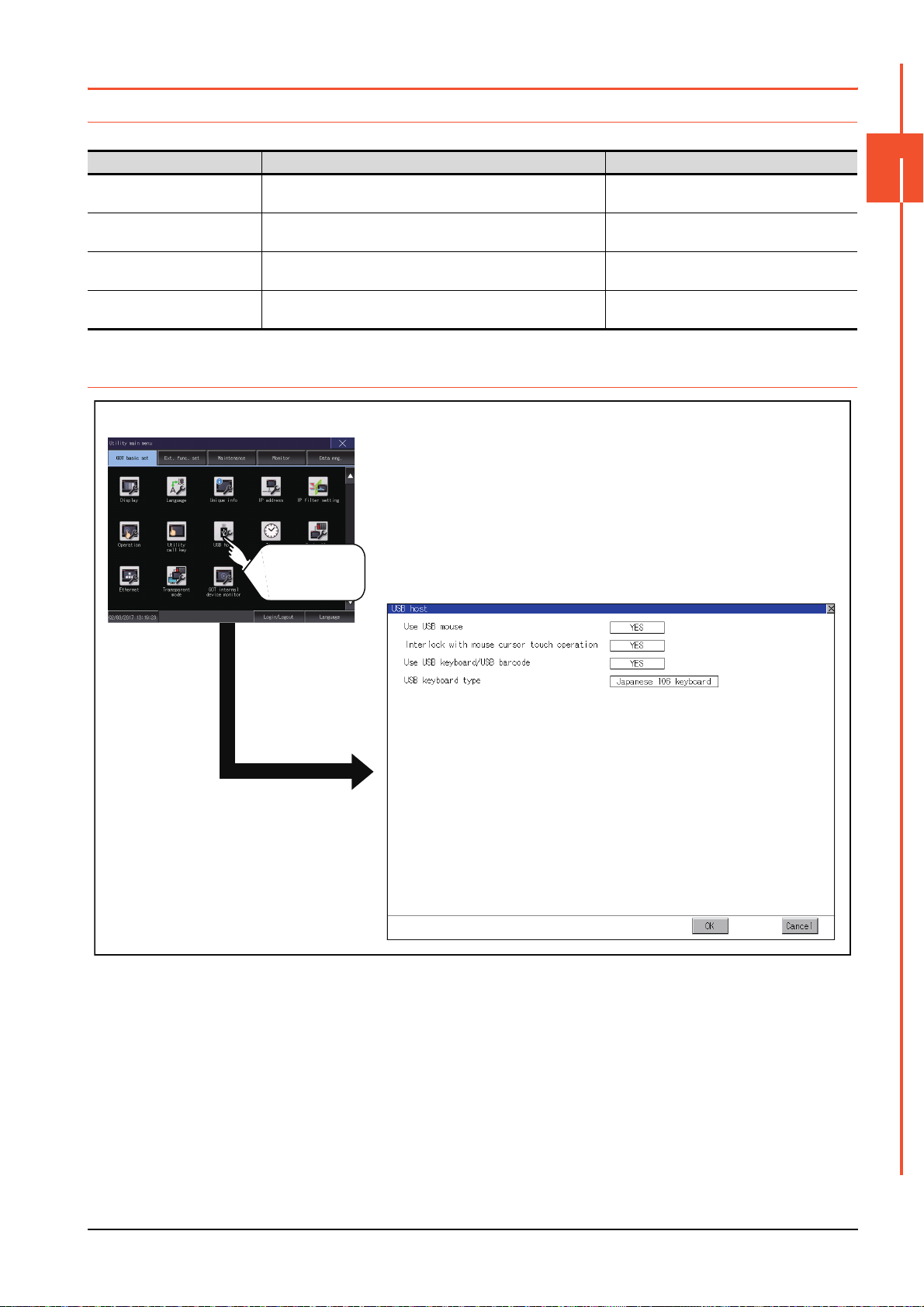
2.8 USB Host
USB host
GOT basic setting
Touch
[USB host].
2.8.1 USB host setting
To install and use the USB mouse/keyboard on the GOT, set the USB mouse/keyboard.
Item Description Setting range
Use USB mouse Set whether to use a USB mouse.
Interlock with mouse cursor touch
operation
Use USB keyboard/USB barcode Set whether to use a USB keyboard or a USB barcode reader.
USB keyboard type Set the USB keyboard type.
The mouse cursor can be moved to the touched position.
YES/NO
<Default: YES>
YES/NO
<Default: YES>
YES/NO
<Default: YES>
Japanese 106 keyboard/English 101 keyboard
<Default: Japanese 106 keyboard>
2.8.2 Display operation of the USB host setting
2
GOT BASIC SETTING
2.8 USB Host
2 - 29
Page 76

2.8.3 Setting operation of USB host
Step 1. To use a USB mouse, touch the current selection of [Use USB mouse].
Switch between the selections with each touch.
(YES NO)
Step 2. To move the mouse cursor to a touched position, touch the current selection of [Interlock with mouse cursor
touch operation].
Switch between the selections with each touch.
(YES NO)
Step 3. To use a USB keyboard or a USB barcode reader, touch the current selection of [Use USB keyboard/USB
barcode].
Switch between the selections with each touch.
(YES NO)
2 - 30
2.8 USB Host
Page 77
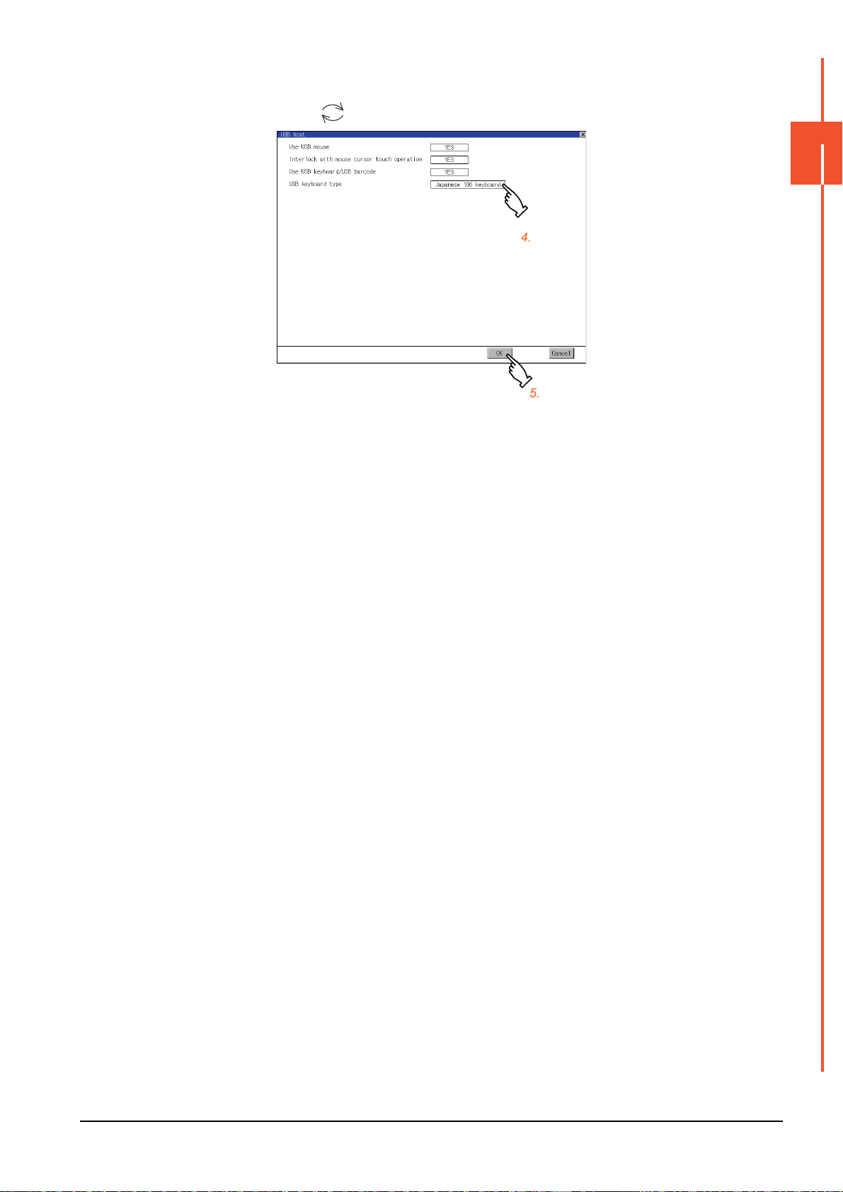
Step 4. To use a USB keyboard, touch the current selection of [USB keyboard type].
Switch between the selections with each touch.
(Japanese 106 keyboard English 101 keyboard)
Step 5. Touch the [OK] button to reflect the new settings and return to the [USB Host] screen.
To cancel the new settings, touch the [Cancel] button to return to the [USB Host] screen.
Step 6. In the [Operation] screen, touch the [OK] button, [Cancel] button, or [×] button to restart the GOT to operate
with the new settings.
2
GOT BASIC SETTING
2.8 USB Host
2 - 31
Page 78
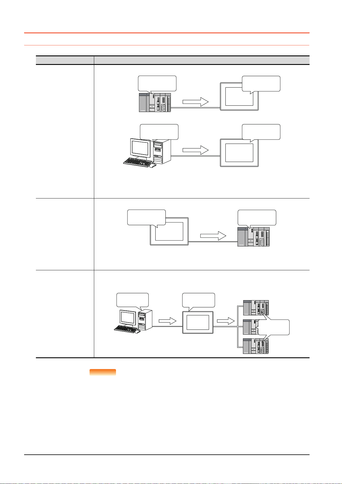
2.9 Time
POINTPOINTPOINT
Clock data
2013/4/1
12:45:07
2013/4/1
12:45:07
Clock data
2013/4/1
12:45:07
2013/4/1
12:45:07
SNTP server
GOT
PLC
GOT
Clock data
2013/4/1
12:45:07
2013/4/1
12:45:07
adjustment
Clock
2013/4/1
12:45:07
2013/4/1
12:45:07
SNTP server
GOT
Time
2013/4/1
12:45:07
function
notification
function
2.9.1 Clock synchronization method
The following shows the clock synchronization method on the GOT.
Clock synchronization method Description
Acquire the clock data of the controller or the SNTP server and change the clock data of the GOT.
Time setting function
When the GOT is powered on, set the clock data of the GOT to that of the controller or the SNTP server.
Since the GOT does not have to hold the clock data while the GOT is powered off, no battery is required.
To set the controller clock data of the controller, refer to the manual of the controller you use.
Notify the clock data of the GOT to the controller to change that of the controller.
Time notification function
Using the clock adjustment
function
and the time notification
function together
At the timing of the trigger, set the clock data of the controller to that of the GOT.
Since the GOT must hold the clock data while the GOT is powered off, a battery is required.
Set the clock data of the GOT in the utility.
Acquire the clock data of the controller or the SNTP server by the clock adjustment function. Then change the clock
data of other controllers by the time notification function.
Then change the clock data of other controllers by the time notification function.
Details of the clock synchronization method
For the details of the clock synchronization method, refer to the following.
➠ GT Designer3 (GOT2000) Screen Design Manual
2 - 32
2.9 Time
Page 79
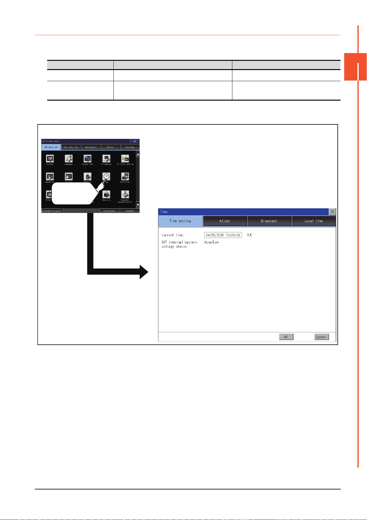
2.9.2 Time setting
Time (Time setting)
GOT basic setting
Touch [Time].
Set the current time.
■1. Time setting
Item Description Reference
Current time
GOT internal battery voltage
status
Carry out the display and setup of GOT clock data.
Displays GOT internal battery voltage status.
■2. Display operation of the time setting
2
➠ 2.9.2 ■3. (1) Current time
➠ 2.9.2 ■3. (2) GOT internal battery voltage
status
GOT BASIC SETTING
2.9 Time
2 - 33
Page 80

■3. Setting procedure for the time setting
(1) Current time
Carry out the display and setting of GOT clock data.
The setup methods of clock data are shown below.
Step 1. Touch the current date and time to display the keyboard and stop the clock update.
Step 2. Input date and time with the keyboard by referring to the table below.
The input date and time are reflected after step 3 is performed.
The day of the week on the input date is displayed automatically.
The following shows the setting range of the date.
Jan. 1, 2000 to Dec. 31, 2099
Key Description
[0] to [9] Input numeric value in cursor position.
,
[Del]
[Enter] Close the keyboard after the input time is displayed in clock display.
[Cancel]
Move the cursor.
Move the cursor to the left by one character when [Del] Key is touched while inputting year, month, day, time, minutes,
seconds.
Cancel the input time and returns the time of clock display to the time at which the keyboard was displayed and close the
keyboard.
Step 3. To reflect the new setting and return to the Main Menu, touch the [OK] button.
To cancel the new setting and return to the Main Menu, touch the [Cancel] button.
(2) GOT internal battery voltage status
Displays battery voltage status.
Display Status
Normal Normal
Low/None Voltage drop or no battery installed
When the battery voltage is low, replace the battery immediately.
Refer to the following for battery replacement procedure.
➠ GOT2000 Series User's Manual (Hardware)
2 - 34
2.9 Time
Page 81

2.9.3 Adjusting the clock
POINTPOINTPOINT
Synchronize the clock data of the GOT with the clock data of the controller.
■1. Clock adjustment setting
Item Description Setting range
Adjust the clock Set whether to use the clock adjustment function.
Mode
Reference CH No.
SNTP IP address
Trigger type
Specify the time zone of target
unit
Time zone
Time difference from GMT
Set the clock adjustment mode.
When selecting [External unit] for [Mode], set a reference
channel of the controller.
When selecting [SNTP server] for [Mode], set the IP
address of the SNTP server.
Touch the [Connection test] button to check the
connection with the SNTP server.
Set the trigger type for the clock adjustment.
• When selecting [Sampling] for [Trigger type], set the
sampling interval for the clock adjustment.
• When selecting [Rise] or [Fall] for [Trigger type],
information on the device set as a trigger is displayed.
Set whether to specify the time zone of the target
controller.
When selecting [Specify the time zone of target unit], set
the time zone.
When selecting [Custom] for [Time zone], set the time
difference based on GMT.
*1
2
Yes (selected)/No (deselected)
<Default: No (deselected)>
External unit/SNTP server
<Default: External unit >
1 to 4
<Default: 1>
0.0.0.0 to 255.255.255.255
<Default: 0.0.0.0>
*2
Trigger type: Rise/Fall/Sampling
<Default: Sampling>
Sampling interval: 1 to 1440
<Default: 60>
*3
Selected/Not selected
<Default: Not selected>
GMT-12:00 to GMT+13:00/Custom
<Default: GMT+9:00>
Hour: -12 to 13
Minute: 0, 15, 30, or 45
<Default: 0 hour 0 minute>
GOT BASIC SETTING
*1 If you set this item to [SNTP server], set [Time zone] to the time zone of the local time.
➠ 2.9.5 Local time
*2 If [Adjust the clock] is deselected or [Trigger Type] is set to [Sampling] in [GOT Setup] in the project data, only [Sampling] is
selectable as the trigger type for the clock adjustment in the utility.
*3 If [Adjust the clock] is deselected or [Trigger Type] is set to [Sampling] in [GOT Setup] in the project data, [No setting] is displayed
in [Device].
Settings of [Adjust] in the utility
Configure the settings in the utility and in [GOT Setup] on GT Designer3 by the same method.
➠ GT Designer3 (GOT2000) Screen Design Manual
2.9 Time
2 - 35
Page 82
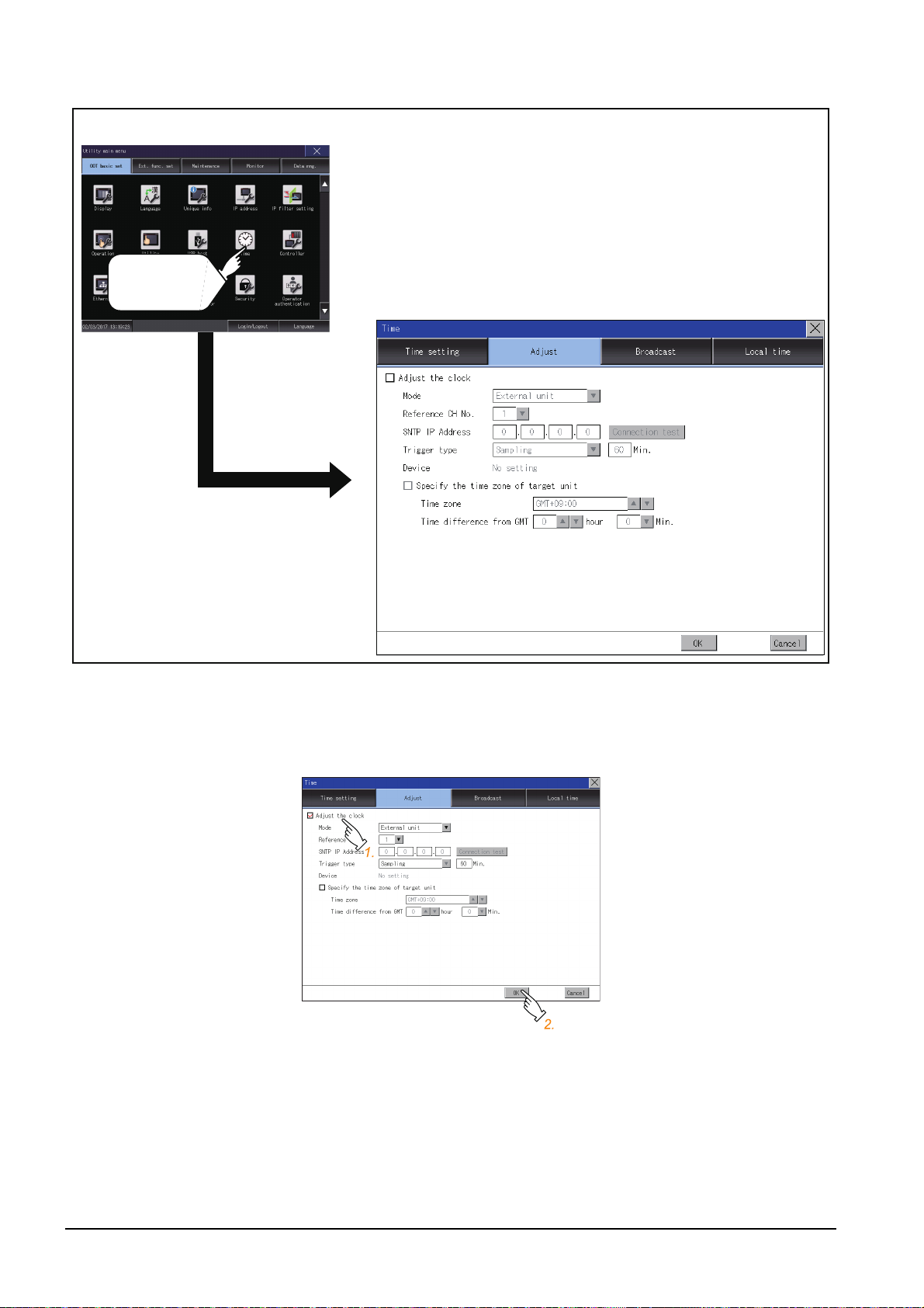
■2. Display operation of the clock adjustment
Time (Time setting)
GOT basic setting
Touch [Time].
■3. Setting procedure for the clock adjustment
(1) Adjust the clock
Step 1.
Step 2. Touch the [OK] button to display a restart confirmation dialog.
To synchronize the clock data of the GOT with the clock data of the controller, select [Adjust the clock].
Restart the GOT to operate with the new setting.
If touch the [Cancel] button, the changed settings are canceled and the screen returns to the Main Menu.
2 - 36
2.9 Time
Page 83

(2) Mode
Step 1.
Step 2. Touch the [OK] button to display a restart confirmation dialog.
(3) Reference CH No.
Step 1.
Touch the setting item and select a setting from the list.
Restart the GOT to operate with the new setting.
If touch the [Cancel] button, the changed settings are canceled and the screen returns to the Main Menu.
Touch the setting item and select a setting from the list.
2
GOT BASIC SETTING
Step 2. Touch the [OK] button to display a restart confirmation dialog.
Restart the GOT to operate with the new setting.
If touch the [Cancel] button, the changed settings are canceled and the screen returns to the Main Menu.
2.9 Time
2 - 37
Page 84

(4) SNTP IP address
Step 1.
Touch the setting item to display a software keyboard.
Input a value for each box with the keyboard.
Step 2. Touch the [Connection test] button to check the connection with the SNTP server.
Step 3. Touch the [OK] button to display a restart confirmation dialog.
Restart the GOT to operate with the new setting.
If touch the [Cancel] button, the changed settings are canceled and the screen returns to the Main Menu.
(5) Trigger type
Step 1.
Touch the setting item and select a setting from the list.
Step 2. If you select [Sampling], set the sampling interval for the clock adjustment.
Touch the entry box on the left side of [Min.] to display a software keyboard.
Input a value with the keyboard.
Step 3. Touch the [OK] button to display a restart confirmation dialog.
Restart the GOT to operate with the new setting.
If touch the [Cancel] button, the changed settings are canceled and the screen returns to the Main Menu.
2 - 38
2.9 Time
Page 85

(6) Specify the time zone of target unit
Step 1.
Step 2. Touch the [OK] button to display a restart confirmation dialog.
(7) Time zone
Step 1.
To specify the time zone of the target controller, select [Specify the time zone of target unit].
Restart the GOT to operate with the new setting.
If touch the [Cancel] button, the changed settings are canceled and the screen returns to the Main Menu.
Touch the up or down button on the right side of the time zone entry box to change the setting.
2
GOT BASIC SETTING
Step 2. Touch the [OK] button to display a restart confirmation dialog.
Restart the GOT to operate with the new setting.
If touch the [Cancel] button, the changed settings are canceled and the screen returns to the Main Menu.
2.9 Time
2 - 39
Page 86

(8) Time difference from GMT
Step 1.
To change the setting of [hour], touch the up or down button on the left side of [hour].
To change the setting of [Min.], touch the pull-down menu button on the left side of [Min.] and select an item
from the list.
Step 2. Touch the [OK] button to display a restart confirmation dialog.
Restart the GOT to operate with the new setting.
If touch the [Cancel] button, the changed settings are canceled and the screen returns to the Main Menu.
2 - 40
2.9 Time
Page 87

2.9.4 Broadcasting the clock data
POINTPOINTPOINT
Notify the clock data of the GOT to the controller for synchronization with the GOT.
■1. Time notification setting
Item Description Setting range
Broadcast the clock data Set whether to use the time notification function.
Broadcast CH No. Set a channel used for the time notification.
Set the trigger type for the time notification.
• When selecting [Sampling] for [Trigger type], set the
Trigger type
Specify the time zone of target
unit
Time zone
Time difference from GMT
*1 If [Broadcast the clock data] is deselected or [Trigger Type] is set to [Sampling] in [GOT Setup] in the project data, only [Sampling]
is selectable as the trigger type for the time notification in the utility.
*2 If [Broadcast the clock data] is deselected or [Trigger Type] is set to [Sampling] in [GOT Setup] in the project data, [No setting] is
displayed for the device.
sampling interval for the time notification.
• When selecting [Rise] or [Fall] for [Trigger type],
information on the device set as a trigger is displayed.
Set whether to specify the time zone of the target
controller.
When selecting [Specify the time zone of target unit], set
the time zone.
When selecting [Custom] for [Time zone], set the time
difference based on GMT.
2
Selected/Not selected
<Default: Not selected>
CH 1, CH 2, CH 3, CH 4
<Default: 1>
*1
Trigger type: Rise/Fall/Sampling
<Default: Sampling>
Sampling interval: 1 to 1440
<Default: 60>
*2
Selected/Not selected
<Default: Not selected>
GMT-12:00 to GMT+13:00/Custom
<Default: GMT+9:00>
Hour: -12 to 13
Minute: 0, 15, 30, or 45
<Default: 0 hour 0 minute>
GOT BASIC SETTING
Settings of [Broadcast] in the utility
Configure the settings in the utility and in [GOT Setup] on GT Designer3 by the same method.
➠ GT Designer3 (GOT2000) Screen Design Manual
2.9 Time
2 - 41
Page 88

■2. Display operation of the time notification
GOT basic setting
Touch [Time].
Time (Broadcast tab)
■3. Setting procedure for the time notification
(1) Broadcast the clock data
Step 1.
Step 2. Touch the [OK] button to display a restart confirmation dialog.
To notify the clock data of the GOT to the controller for synchronization with the GOT, select [Broadcast the
clock data].
Restart the GOT to operate with the new setting.
If touch the [Cancel] button, the changed settings are canceled and the screen returns to the Main Menu.
2 - 42
2.9 Time
Page 89

(2) Broadcast CH No.
Step 1.
Touch a channel number to select it.
Step 2. Touch the [OK] button to display a restart confirmation dialog.
Restart the GOT to operate with the new setting.
If touch the [Cancel] button, the changed settings are canceled and the screen returns to the Main Menu.
(3) Trigger type
Step 1.
Touch the setting item and select a setting from the list.
2
GOT BASIC SETTING
Step 2. If you select [Sampling], set the sampling interval for the time notification.
Touch the entry box on the left side of [Min.] to display a software keyboard.
Input a value with the keyboard.
Step 3. Touch the [OK] button to display a restart confirmation dialog.
Restart the GOT to operate with the new setting.
If touch the [Cancel] button, the changed settings are canceled and the screen returns to the Main Menu.
2.9 Time
2 - 43
Page 90
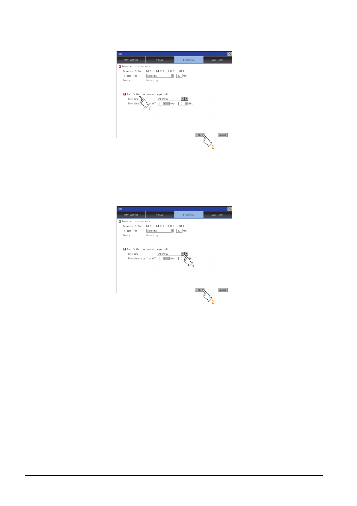
(4) Specify the time zone of target unit
Step 1.
To specify the time zone of the target controller, select [Specify the time zone of target unit].
Step 2. Touch the [OK] button to display a restart confirmation dialog.
Restart the GOT to operate with the new setting.
If touch the [Cancel] button, the changed settings are canceled and the screen returns to the Main Menu.
(5) Time zone
Step 1.
Touch the up or down button on the right side of the time zone entry box to change the setting.
Step 2. Touch the [OK] button to display a restart confirmation dialog.
Restart the GOT to operate with the new setting.
If touch the [Cancel] button, the changed settings are canceled and the screen returns to the Main Menu.
2 - 44
2.9 Time
Page 91

(6) Time difference from GMT
Step 1.
Step 2. Touch the [OK] button to display a restart confirmation dialog.
To change the setting of [hour], touch the up or down button on the left side of [hour].
To change the setting of [Min.], touch the pull-down menu button on the left side of [Min.] and select an item
from the list.
Restart the GOT to operate with the new setting.
If touch the [Cancel] button, the changed settings are canceled and the screen returns to the Main Menu.
2
GOT BASIC SETTING
2.9 Time
2 - 45
Page 92

2.9.5 Local time
GOT basic setting
Touch [Time].
Time (Local time)
Set the time zone of the local time in the clock data of the GOT.
■1. Local time setting
Item Description Setting range
Specify time zone
Time zone When selecting [Specify time zone], set the time zone.
Time difference from GMT
■2. Display operation of the local time
Set whether to specify the time zone in the clock data of
the GOT.
When selecting [Custom] for [Time zone], set the time
difference based on GMT.
Selected/Not selected
<Default: Not selected>
GMT-12:00 to GMT+13:00/Custom
<Default: GMT+9:00>
Hour: -12 to 13
Minute: 0, 15, 30, or 45
<Default: 0 hour 0 minute>
2 - 46
2.9 Time
Page 93
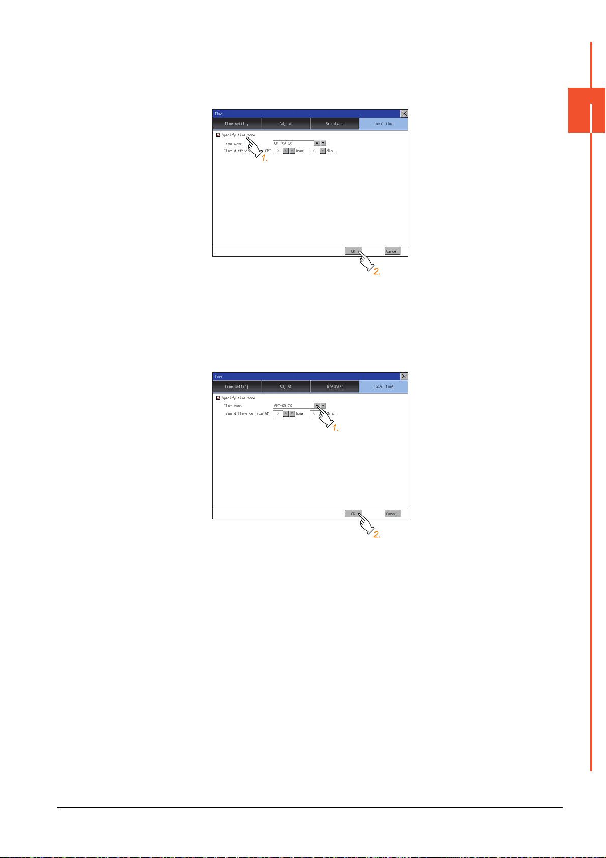
■3. Setting procedure for the local time
(1) Specify time zone
Step 1.
Step 2. Touch the [OK] button to display a restart confirmation dialog.
(2) Time zone
Step 1.
To set the time zone, select [Specify time zone].
Restart the GOT to operate with the new setting.
If touch the [Cancel] button, the changed settings are canceled and the screen returns to the Main Menu.
Touch the up or down button on the right side of the time zone entry box to change the setting.
2
GOT BASIC SETTING
Step 2. Touch the [OK] button to display a restart confirmation dialog.
Restart the GOT to operate with the new setting.
If touch the [Cancel] button, the changed settings are canceled and the screen returns to the Main Menu.
2.9 Time
2 - 47
Page 94
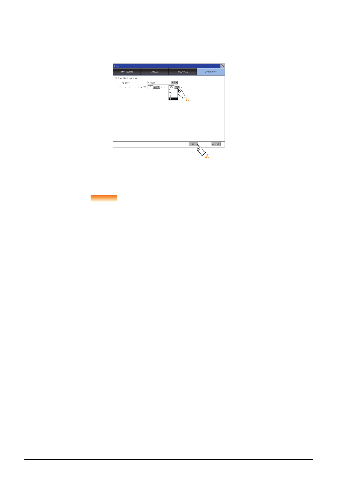
(3) Time difference from GMT
POINTPOINTPOINT
Step 1.
To change the setting of [hour], touch the up or down button on the left side of [hour].
To change the setting of [Min.], touch the pull-down menu button on the left side of [Min.] and select an item
from the list.
Step 2. Touch the [OK] button to display a restart confirmation dialog.
Restart the GOT to operate with the new setting.
If touch the [Cancel] button, the changed settings are canceled and the screen returns to the Main Menu.
(1) When connecting to an external device which does not have clock function
If the GOT is connected to an external device (such as a PLC or microcomputer) that has no
clock function, setting [Adjust] or [Broadcast] does not synchronize the clock data between
the GOT and external device.
For the list of the PLCs having the clock function, refer to the following.
➠ GOT2000 Series Connection Manual for the controller used
For details of [Adjust] and [Broadcast], refer to the following.
➠ GT Designer3 (GOT2000) Screen Design Manual
(2) Time setting and battery
The GOT built-in battery is not connected to the GOT at factory default.
To use the time notification function, connect the GOT built-in battery and then configure the
time setting.
For information on how to connect the GOT built-in battery, refer to the following.
➠ GOT2000 Series User's Manual (Hardware)
(3) Time display
The GOT displays the current time to which the local time setting is reflected.
For the local time setting, refer to the following.
2 - 48
➠ 2.9.5 Local time
(4) Changing times
If you have changed the present time of the GOT where the time setting function or the time
notification function was being used, the new time setting will be written to the PLC.
Thus, you can change the time of the PLC from the GOT even when the time setting function
is being used.
For details of [Adjust] and [Broadcast], refer to the following.
➠ GT Designer3 (GOT2000) Screen Design Manual
2.9 Time
Page 95

2.10 Controller
2.10.1 Controller setting
Configure controller settings.
The items which can be set are shown below. When each item part is touched, the respective setting becomes possible.
Function Description
Assign Ethernet I/F
Channel-Driver assign Change the assignment of channel No. and communication driver name.
Channel no. (Ch No.) setting Set the channel numbers of the communication interface (Standard interface/Extend interface).
5 V power supply
Communication Detail Setting Set communication parameters of communication devices.
Change the assignment of channel No. and communication driver name of the device connected using the
Ethernet interface.
When connecting a controller to the RS-232 interface, whether to supply 5 V DC power or not to the controller
through 9 pins can be selected.
2
GOT BASIC SETTING
2.10 Controller
2 - 49
Page 96

2.10.2 Communication detail setting display operation
Controller(For GT27)
GOT basic setting
Touch
[Controller].
2 - 50
2.10 Controller
Page 97

2.10.3 Controller contents
1)
6)
4)
2)
5)
3)
This section describes setting items and display contents for a controller.
2
GOT BASIC SETTING
1) Channel-Driver assign
• Assignment of communication drivers to channels
Communication drivers installed in the GOT can be assigned to channels.
Even without setting [Controller Setting] on GT Designer3, communication with controller is available by
assigning channel No. with this function.
➠ 2.10.4 ■2. Channel-Driver assign operation
• Changing the assignment of communication drivers to channels
Without using GT Designer3, the assignment of communication drivers to channels can be changed.
When change a communication driver, the alternative communication driver has to be installed in GOT in
advance.
2) Standard interface display box
The standard communication interfaces of the GOT are displayed.
There are the following 4 types.
RS-232 For communicating with a controller
RS-422/485 For communicating with a controller
USB (Device) For communicating with a personal computer (GT Designer3)
Ethernet For communicating with a personal computer (GT Designer3) or a controller
3) Extension interface display box
The name of the unit installed in the extension interface is displayed.
(Displays [None] when any unit is not mounted.)
For details of each unit, refer to the following.
➠ GOT2000 Series User's Manual (Hardware)
2.10 Controller
2 - 51
Page 98

4) Channel number specification menu box
Set the channel number used for a standard interface or extension interface.
For drivers that can be assigned for channels, refer to (5) in this section.
0 Set when the communication interface is not used.
1 to 4
*1*2
5 to 8
*1
9
A
- When the Ethernet communication unit is used, the channel number is fixed to [-].
Set when connecting to a controller.
(Except a barcode reader, an RFID controller, and a personal computer)
Set when connecting to a barcode reader, an RFID controller or a PC.
Set when connecting to a personal computer (GT Designer3).
When the USB interface is used, the channel number is fixed to [9].
Set this item when using the following functions.
• Gateway function
• MES interface function
• Ethernet download
• Report function
• Hard copy function (for output to a printer)
• Video display function
• RGB display function
• RGB output function
• External I/O function
• Operation panel function
• Sound output function
• Multimedia function
• Remote personal computer operation function
• VNC server function
• Wireless LAN connection function
*1 The channels cannot be assigned with the Ethernet I/F assignment.
*2 The same device cannot be used for Ch No.5 to Ch No.8 simultaneously.
For restrictions on external devices, refer to the following.
➠ GOT2000 Series Connection Manual for the controller used
➠ GT Designer3 (GOT2000) Screen Design Manual
5) Communication driver display box
The name of the communication driver assigned to a channel or the communication driver set in the controller
setting of GT Designer3 is displayed.
For details of drivers to be displayed, refer to the following.
➠ GOT2000 Series Connection Manual for the controller used
➠ GT Designer3 (GOT2000) Screen Design Manual
Display [None] in the driver display box in case of the followings.
• The communication driver is not installed.
• In the channel number specification menu box, [0] is set.
• The type of the communication unit mounted on the extension interface does not correspond to the set
• communication driver.
For how to set the communication driver, refer to the following.
➠ 2.10.4 ■2. Channel-Driver assign operation
6) Assign Ethernet I/F
The communication settings for the Ethernet connection can be made.
Ethernet I/F Assignment can assign up to four channels per interface.
➠ 2.10.4 ■1. Assign Ethernet I/F operation
2 - 52
2.10 Controller
Page 99

POINT
POINT
POINT
Precautions for communications between GOT and controller
(1) Installing a communication driver and downloading communication setting data
To communicate with a controller, perform the following to the communication interface
1) Install a communication driver (up to four drivers).
2) Assign a channel number and the communication driver to the communication interface.
3) Download the project data including the setting configured in step 2) above.
Refer to the following for details.
➠ GOT2000 Series Connection Manual for the controller used
GT Designer3 (GOT2000) Screen Design Manual
(2) When the communication setting data is not downloaded.
The GOT automatically assigns the installed communication driver in the order of 1) to 3) as
follows.
(This automatic assignment is applied to the extension interface only.)
2
GOT BASIC SETTING
1)
2)
3)
1): ChNo.1, Communication driver installed at 1st
2): ChNo.2, Communication driver installed at 2nd
3): ChNo.3, Communication driver installed at 3rd
(a) After communication driver is assigned automatically.
When saving the settings to the GOT with [OK] button after the automatic assignment of
communication driver, automatic assignment will not be performed at the next time and
after.
(b) Priority against [Controller Setting] of GT Designer3
If download the communication settings to the GOT with GT Designer3 after the
automatic assignment, the GOT will operate with the communication settings of GT
Designer3. (The GOT operates with the latest communication settings.)
(3) When the communication driver does not match with the unit that is installed in the
GOT
An error is displayed on the GOT when displaying [Communication setting].
If an error is displayed, confirm the combination of the communication driver and
communication unit.
Refer to the following manual for the combination.
➠ GOT2000 Series Connection Manual for the controller used
2.10 Controller
2 - 53
Page 100

2.10.4 Controller setting operation
■1. Assign Ethernet I/F operation
The following describes how to operate the Ethernet I/F assign.
The setting operation is same as that of the communication setting screen.
Step 1. Touch the [Assign Ethernet I/F] button in [Communication setting].
Step 2. After the screen shown below is displayed, touch the channel number specification menu BOX when
changing the channel number.
➠ ■3. Channel number setting operation
Step 3. For changing the parameter settings, touch the driver display BOX.
➠ 2.10.5 Communication detail setting
2 - 54
2.10 Controller
 Loading...