

Page 1

Page 2

Page 3
SAFETY PRECAUTIONS
(Always read these precautions before using this equipment.)
Before using this product, please read this manual and the relevant manuals introduced in this manual
carefully and pay full attention to safety to handle the product correctly.
The precautions given in this manual are concerned with this product.
In this manual, the safety precautions are ranked as "DANGER" and "CAUTION".
DANGER
CAUTION
Note that the caution level may lead to a serious accident according to the circumstances. Always follow
the instructions of both levels because they are important to personal safety.
Please save this manual to make it accessible when required and always forward it to the end user.
Indicates that incorrect handling may cause hazardous
conditions, resulting in death or severe injury.
Indicates that incorrect handling may cause hazardous
conditions, resulting in medium or slight personal injury or
physical damage.
[DESIGN PRECAUTIONS]
DANGER
Some failures of the GOT or cable may keep the outputs on or off.
An external monitoring circuit should be provided to check for output signals which may lead to a
serious accident.
Not doing so can cause an accident due to false output or malfunction.
If a communication error (including cable disconnection) occurs while monitoring on the GOT,
communication between the GOT and PLC CPU is suspended, and the GOT becomes inoperative
as described below:
(1) GT1155-QSBD, GT1150-QLBD: Become inoperative
(2) PLC CPU shuts down and the GOT becomes inoperative.
For the system configuration with GOT, assuming communication error occurs in the GOT, the
switches for critical operation to the system should be set in the device other than GOT. False output
or malfunction may occur.
Do not use the GOT as the warning device that may cause a serious accident.
An independent and redundant hardware or mechanical interlock is required to configure the device
that displays and outputs serious warning.
Failure to observe this instruction may result in an accident due to incorrect output or malfunction.
A - 1
Page 4
[DESIGN PRECAUTIONS]
DANGER
Incorrect operation of the touch switch(s) may lead to a serious accident if the GOT backlight is gone
out.
When the GOT backlight goes out, the POWER LED flickers (green/orange) and the display section
turns black and causes the monitor screen to appear blank, while the input of the touch switch(s)
remains active.
This may confuse an operator in thinking that the GOT is in "screensaver" mode, who then tries to
release the GOT from this mode by touching the display section, which may cause a touch switch to
operate.
Note that the following occurs on the GOT when the backlight goes out.
•The POWER LED flickers (green/orange) and the monitor screen appears blank
CAUTION
Do not bundle the control and communication cables with main-circuit, power or other wiring.
Run the above cables separately from such wiring and keep them a minimum of 100mm (3.94in.)
apart. Not doing so noise can cause a malfunction.
Do not press the GOT display section with a pointed material as a pen or driver.
Doing so can result in a damage or failure of the display section.
[MOUNTING PRECAUTIONS]
DANGER
Be sure to shut off all phases of the external power supply used by the system before mounting or
removing the GOT to/from the panel.
Not doing so can cause the unit to fail or malfunction.
Be sure to shut off all phases of the external power supply used by the system before mounting or
removing the option function board on to/from the GOT.
Not doing so can cause the unit to fail or malfunction.
When installing the option function board or battery, or operating the reset switch, wear an earth
band etc. to avoid the static electricity.
The static electricity can cause the unit to fail or malfunction.
A - 2
Page 5
[MOUNTING PRECAUTIONS]
CAUTION
Use the GOT in the environment that satisfies the general specifications described in this manual.
Not doing so can cause an electric shock, fire, malfunction or product damage or deterioration.
When mounting the GOT to the control panel, tighten the mounting screws in the specified torque
range.
Undertightening can cause the GOT to drop, short circuit or malfunction.
Overtightening can cause a drop, short circuit or malfunction due to the damage of the screws or the
GOT.
Securely connect the option function board to the connector provided for the board.
When inserting/removing a CF card into/from the GOT, turn the CF card access switch off in
advance.
Failure to do so may corrupt data within the CF card.
When inserting a CF card into the GOT, push it into the insertion slot until the CF card eject button
will pop out.
Failure to do so may cause a malfunction due to poor contact.
When removing a CF card from the GOT, make sure to support the CF card by hand, as it may pop
out.
Failure to do so may cause the CF card to drop from the GOT and break.
When using the GOT in the environment of oil or chemicals, use the protective cover for oil.
Failure to do so may cause failure or malfunction due to the oil or chemical entering into the GOT.
[WIRING PRECAUTIONS]
DANGER
Be sure to shut off all phases of the external power supply used by the system before wiring.
Failure to do so may result in an electric shock, product damage or malfunctions.
Please make sure to ground FG terminal of the GOT power supply section by applying 100 or less
which is used exclusively for the GOT.
Not doing so may cause an electric shock or malfunction.
Correctly wire the GOT power supply section after confirming the rated voltage and terminal
arrangement of the product.
Not doing so can cause a fire or failure.
Tighten the terminal screws of the GOT power supply section in the specified torque range.
Undertightening can cause a short circuit or malfunction.
Overtightening can cause a short circuit or malfunction due to the damage of the screws or the GOT.
Exercise care to avoid foreign matter such as chips and wire offcuts entering the GOT.
Not doing so can cause a fire, failure or malfunction.
A - 3
Page 6
[WIRING PRECAUTIONS]
CAUTION
Plug the communication cable into the connector of the connected unit and tighten the mounting and
terminal screws in the specified torque range.
Undertightening can cause a short circuit or malfunction.
Overtightening can cause a short circuit or malfunction due to the damage of the screws or unit.
Insert the bus cables for QnA, ACPU, and motion controller (A series) into the GOT's bus interface
connectors until they click into the place.
Check for proper insertion to avoid malfunctions.
[TEST OPERATION PRECAUTIONS]
DANGER
Before performing the test operations of the user creation monitor screen (such as turning ON or
OFF bit device, changing the word device current value, changing the settings or current values of
the timer or counter, and changing the buffer memory current value), read through the manual
carefully and make yourself familiar with the operation method.
During test operation, never change the data of the devices which are used to perform significant
operation for the system.
False output or malfunction can cause an accident.
[STARTUP/MAINTENANCE PRECAUTIONS]
DANGER
When power is on, do not touch the terminals.
Doing so can cause an electric shock or malfunction.
Connect the battery correctly.
Do not discharge, disassemble, heat, short, solder or throw the battery into the fire.
Incorrect handling may cause the battery to generate heat, burst or take fire, resulting in injuries or
fires.
Before starting cleaning or terminal screw retightening, always switch off the power externally in all
phases.
Not switching the power off in all phases can cause a unit failure or malfunction.
Undertightening can cause a short circuit or malfunction.
Overtightening can cause a short circuit or malfunction due to the damage of the screws or unit.
A - 4
Page 7
[STARTUP/MAINTENANCE PRECAUTIONS]
CAUTION
Do not disassemble or modify the unit.
Doing so can cause a failure, malfunction, injury or fire.
Do not touch the conductive and electronic parts of the unit directly.
Doing so can cause a unit malfunction or failure.
The cables connected to the unit must be run in ducts or clamped.
Not doing so can cause the unit or cable to be damaged due to the dangling, motion or accidental
pulling of the cables or can cause a malfunction due to a cable connection fault.
When unplugging the cable connected to the unit, do not hold and pull the cable portion.
Doing so can cause the unit or cable to be damaged or can cause a malfunction due to a cable
connection fault.
Do not drop or apply any impact to the battery.
If any impact has been applied, discard the battery and never use it.
The battery may be damaged by the drop or impact.
Before touching the unit, always touch grounded metal, etc. to discharge static electricity from
human body, etc.
Not doing so can cause the unit to fail or malfunction.
Replace battery with GT11-50BAT by Mitsubishi electric Co. only.
Use of another battery may present a risk of fire or explosion.
Dispose of used battery promptly.
Keep away from children. Do not disassemble and do not dispose of in fire.
[DISPOSAL PRECAUTIONS]
CAUTION
When disposing of the product, handle it as industrial waste.
When disposing of batteries, separate them from other wastes according to the local regulations.
(For details of the battery directive in EU member states, refer to 17.4
.)
[TRANSPORTATION PRECAUTIONS]
CAUTION
When transporting lithium batteries, make sure to treat them based on the transport regulations.
(Refer to Appendix 3 for details of the regulated units.)
Before transporting the GOT, turn the GOT power on and check that the battery voltage status is
normal on the Time setting & display screen (utilities screen). In addition, confirm that the adequate
battery life remains on the rating plate.
Transporting the GOT with the low battery voltage or the battery the reached battery life may
unstabilize the backup data unstable during transportation.
Make sure to transport the GOT main unit and/or relevant unit(s) in the manner they will not be
exposed to the impact exceeding the impact resistance described in the general specifications of this
manual, as they are precision devices.
Failure to do so may cause the unit to fail.
Check if the unit operates correctly after transportation.
A - 5
Page 8
REVISIONS
The manual number is given on the bottom left of the back cover.
Print Date Manual Number Ver. Revision
Mar., 2005 JY997D17501 A First edition
Oct., 2005 JY997D17501 B
Partial correcting
ABOUT MANUALS, ABBREVIATIONS AND GENERIC TERMS IN THIS
MANUAL, Chapter 1, Section 2.2, 3.1, 3.2, 4.2, Chapter 6, 7, Section 8.1,
8.4, 8.5, 9.2, 9.3, Chapter 10, 11, 12, 13, Section 14.1, 14.3, 16.2, 16.3,
17.4, Chapter 18, Appendix2, Appendix 4
Additions
Section 13.6, 16.4
Nov., 2006 JY997D17501 C
May., 2007 JY997D17501 D
Nov., 2007 JY997D17501 E
Partial correcting
ABOUT MANUALS, ABBREVIATIONS AND GENERIC TERMS IN THIS
MANUAL, Section 2.2, 7.1, 9.2, 9.3, 10.1, Chapter 11, Section 13.1,
Chapter 14, Section 16.3, 16.4, Appendix1, Appendix2, Appendix 4
Additions
Section 7.2, 13.7, 14.8, 14.9
Partial revisions
ABBREVIATIONS AND GENERIC TERMS IN THIS MANUAL, ABOUT
MANUALS, Section 4.1, Appendix 4
Additions
Section 1.1, 2.2, 2.2.1, 2.2.2, 3.2, 3.3, 3.4, 4.2, Chapter 5, Section 6.1, 6.5,
7.1, 8.1.2, 8.3, 10.1.3, 11.2.1, 13.1.3, 16.4, 18.3, Appendix 1, Appendix 2
Partial revisions
ABBREVIATIONS AND GENERIC TERMS IN THIS MANUAL, ABOUT
MANUALS, Appendix 4
Additions
Section 2.2, Chapter 3, Section 4.2, Chapter 5, Section 6.1, 6.5, 7.1, 8.1,
8.3, 8.4, 10.1, 11.2.1, 13.1, 14.7, 16.4, Appendix 1
Jan., 2008 JY997D17501 F
A - 6
Partial revisions
ABBREVIATIONS AND GENERIC TERMS IN THIS MANUAL, ABOUT
MANUALS, Section 8.3, 14.9, Appendix 4
Additions
Chapter 2, Section 3.3, 4.2, Chapter 5, Section 6.1, 7.1, 10.1
Page 9
The manual number is given on the bottom left of the back cover.
Print Date Manual Number Ver. Revision
Oct., 2008 JY997D17501 G
Partial revisions
ABBREVIATIONS AND GENERIC TERMS IN THIS MANUAL, ABOUT
MANUALS, Section 3.1, 3.2, 3.3, 8.8, 10.2, Appendix 4
Mar., 2009 JY997D17501 H
Jul., 2009 JY997D17501 J
Oct., 2009 JY997D17501 K
Apr., 2010 JY997D17501 L
Oct., 2010 JY997D17501 M
Jan., 2011 JY997D17501 N
Apr., 2011 JY997D17501 P
Partial revisions
SAFETY PRECAUTIONS, ABBREVIATIONS AND GENERIC TERMS,
HOW TO READ THIS MANUAL, Chapter 2, 3, Section 4.2, 8.4, 17.4,
Appendix 1, Appendix 4
Additions
Section 8.9, 8.10
Partial revisions
Section 2.1, 3.3, 4.2, Chapter 5, Section 8.9, 8.10
Partial revisions
ABBREVIATIONS AND GENERIC TERMS, HOW TO READ THIS
MANUAL, Chapter 1, Section 2.2, 3.2, 4.1, 8.3, 8.9, Chapter 9, 10, 11, 12,
13, 14, 16, 17, 18, Appendix 2
Additions
Section 14.2, 14.3, 14.4
Partial revisions
SAFETY PRECAUTIONS, ABBREVIATIONS AND GENERIC TERMS,
Chapter 1, 2, 3, 5, 8, 14, 16, 17, Index
Partial revisions
ABBREVIATIONS AND GENERIC TERMS, HOW TO READ THIS
MANUAL, Chapter 2, Section 3.2, Chapter 5, Section 7.1, Chapter 8,
Section 9.3, Section 11.3.3, Chapter 13, Section 16.4, Appendix 4
Partial revisions
ABBREVIATIONS AND GENERIC TERMS, HOW TO READ THIS
MANUAL, Section 4.2, 6.5, 9.3.1, 11.5.3
Partial revisions
HOW TO READ THIS MANUAL, Section 5.2, 8.3
Partial additions
ABBREVIATIONS AND GENERIC TERMS, Section 3.2, 6.2, 6.5, 11.2
This manual confers no industrial property rights or any rights of any other kind, nor does it confer any patent licenses.
Mitsubishi Electric Corporation cannot be held responsible for any problems involving industrial property rights which may
occur as a result of using the contents noted in this manual.
© 2005 MITSUBISHI ELECTRIC CORPORATION
A - 7
Page 10

INTRODUCTION
Thank you for choosing the Mitsubishi Graphic Operation Terminal.
Before using the equipment, please read this manual carefully to use the equipment to its optimum.
OUTLINE PRECAUTIONS
• This manual provides information for the use of the graphic operation terminal. The manual has been written
to be used by trained and competent personnel. The definition of such a person or persons is as follows;
1) Any engineer who is responsible for the planning, design and construction of automatic equipment using
the product associated with this manual should be of a competent nature, trained and qualified to the local
and national standards required to fulfill that role. These engineers should be fully aware of all aspects of
safety with regards to automated equipment.
2) Any commissioning or service engineer must be of a competent nature, trained and qualified to the local
and national standards required to fulfill that job. These engineers should also be trained in the use and
maintenance of the completed product. This includes being completely familiar with all associated
documentation for the said product. All maintenance should be carried out in accordance with established
safety practices.
3) All operators of the completed equipment should be trained to use that product in a safe and coordinated
manner in compliance to established safety practices. The operators should also be familiar with
documentation which is connected with the actual operation of the completed equipment.
Note: the term 'completed equipment' refers to a third party constructed device which contains or uses the
product associated with this manual.
• This product has been manufactured as a general-purpose part for general industries, and has not been
designed or manufactured to be incorporated in a device or system used in purposes related to human life.
• Before using the product for special purposes such as nuclear power, electric power, aerospace, medicine or
passenger movement vehicles, consult with Mitsubishi Electric.
• This product has been manufactured under strict quality control. However when installing the product where
major accidents or losses could occur if the product fails, install appropriate backup or failsafe functions in the
system.
• When using this product combining other products, please confirm the standard and the code, or regulation
which a user should suit. Moreover, please confirm the compatibility of this product to the system, machine,
and apparatus with which a user is used for user itself.
• If in doubt at any stage of the installation of the product always consult a professional electrical engineer who
is qualified and trained to the local and national standards. If in doubt about the operation or use, please
consult the nearest Mitsubishi Electric distributor.
• Since the example indicated by this manual, technical bulletin, the catalog, etc. is reference, please use it
after confirming the function and safety of equipment and system when employing. Mitsubishi Electric will
accept no responsibility for actual use of the product based on these illustrative examples.
• About this manual content, specification etc. may be changed without a notice for improvement.
• The information in this manual has been carefully checked and is believed to be accurate; however, you have
noticed a doubtful point, a doubtful error, etc., please contact the nearest Mitsubishi Electric distributor.
A - 8
Page 11

CONTENTS
SAFETY PRECAUTIONS ...............................................................................................A-1
REVISIONS.....................................................................................................................A-6
INTRODUCTION.............................................................................................................A-8
OUTLINE PRECAUTIONS..............................................................................................A-8
CONTENTS ....................................................................................................................A-9
ABBREVIATIONS AND GENERIC TERMS..................................................................A-17
HOW TO READ THIS MANUAL ...................................................................................A-22
1. OVERVIEW.......................................................... 1-1 to 1-5
1.1 Features .....................................................................................................................1-4
1.2 Rough Pre-operation Procedure ................................................................................1-5
2. SYSTEM CONFIGURATION ............................. 2-1 to 2-13
2.1 Overall Configuration .................................................................................................2-1
2.2 Component List .......................................................................................................... 2-2
2.2.1 GOT (GT11)....................................................................................................................................2-4
2.2.2 Option (Optional components for GT11)......................................................................................... 2-5
3. SPECIFICATIONS ............................................... 3-1 to 3-9
3.1 General Specifications ...............................................................................................3-1
3.2 Performance Specifications .......................................................................................3-2
3.3 Built-in Interface Specifications .................................................................................. 3-6
3.4 Power Supply Specifications...................................................................................... 3-8
4. PART NAME........................................................ 4-1 to 4-4
4.1 Front Panel.................................................................................................................4-1
4.2 Back Panel ................................................................................................................. 4-2
5. EMC DIRECTIVE ............................................... 5-1 to 5-10
5.1 Requirements for Conformance to EMC Directive ..................................................... 5-2
5.1.1 Standards applicable to the EMC Directive .................................................................................... 5-2
5.1.2 Control cabinet................................................................................................................................ 5-3
5.1.3 Grounding ....................................................................................................................................... 5-4
5.2 System Configuration when EMC Directive is Applicable .......................................... 5-5
5.2.1 About models applicable to the EMC Directive...............................................................................5-5
5.2.2 Connection format...........................................................................................................................5-6
5.3 Wiring Precautions the Part which Matches the EMC Directives............................... 5-7
5.3.1 About the cable used ...................................................................................................................... 5-7
5.3.2 Method to connect the power wire and ground wire ....................................................................... 5-9
5.3.3 Grounding the cable...................................................................................................................... 5-10
A - 9
Page 12

6. INSTALLATION....................................................6-1 to 6-7
6.1 Control Panel Inside Dimensions for Mounting GOT..................................................6-2
6.2 Panel Cutting Dimensions ..........................................................................................6-4
6.3 Mounting Position.......................................................................................................6-4
6.4 Control Panel Temperature and Mounting Angle .......................................................6-5
6.5 Installation Procedure.................................................................................................6-6
7. WIRING.................................................................7-1 to 7-8
7.1 Power Supply Wiring ..................................................................................................7-2
7.1.1 Wiring example ............................................................................................................................... 7-2
7.1.2 The cause of malfunctions related wiring/Remedy .........................................................................7-4
7.2 Wiring inside and outside the panel............................................................................7-6
7.2.1 Wiring inside ................................................................................................................................... 7-6
7.2.2 Outside the panel............................................................................................................................7-6
7.2.3 Attaching surge killers to control equipment ...................................................................................7-7
7.2.4 Wiring the FG wire of the BUS cable .............................................................................................. 7-8
8. OPTION ..............................................................8-1 to 8-19
8.1 CF Card......................................................................................................................8-1
8.1.1 Applicable CF card.......................................................................................................................... 8-1
8.1.2 Installing and removing procedures of the CF card ........................................................................8-2
8.2 Memory Card Adaptor ................................................................................................8-4
8.2.1 Applicable memory card adaptor .................................................................................................... 8-4
8.2.2 Installing procedure of the CF card into a memory card adaptor.................................................... 8-4
8.3 Option Function Board................................................................................................8-5
8.3.1 Applicable option function board..................................................................................................... 8-5
8.3.2 Part names...................................................................................................................................... 8-5
8.3.3 How to install or remove the option function board ......................................................................... 8-6
8.4 Battery ........................................................................................................................8-7
8.4.1 Applicable battery ........................................................................................................................... 8-7
8.4.2 Battery specifications ......................................................................................................................8-7
8.4.3 Battery replacement procedure.......................................................................................................8-7
8.5 Protective Sheet .......................................................................................................8-10
8.5.1 Applicable protective sheet ...........................................................................................................8-10
8.5.2 Installing procedure.......................................................................................................................8-10
8.6 USB Environmental Protection Cover ......................................................................8-11
8.6.1 Applicable USB environmental protection cover ...........................................................................8-11
8.6.2 Installing procedure.......................................................................................................................8-11
8.7 Stand ........................................................................................................................8-12
8.7.1 Applicable stand............................................................................................................................ 8-12
8.7.2 Installing procedure.......................................................................................................................8-12
8.8 Protective cover for oil ..............................................................................................8-13
8.8.1 Applicable protective cover for oil .................................................................................................8-13
8.8.2 Installation procedure....................................................................................................................8-13
8.9 Serial Multi-Drop Connection Unit ............................................................................8-16
8.9.1 Serial multi-drop connection unit...................................................................................................8-16
8.9.2 Applicable serial multi-drop connection unit..................................................................................8-17
8.9.3 Part name ..................................................................................................................................... 8-17
8.9.4 Installation..................................................................................................................................... 8-18
A - 10
Page 13

8.9.5 Caution for compliance with EMC Directive.................................................................................. 8-18
8.10 Connector Conversion Adapter.............................................................................. 8-19
8.10.1 Applicable connector conversion adapter ................................................................................... 8-19
8.10.2 Installing procedure..................................................................................................................... 8-19
9. UTILITY FUNCTION .......................................... 9-1 to 9-11
9.1 Utility Execution.......................................................................................................... 9-1
9.2 Utility Function List ..................................................................................................... 9-2
9.3 Utility Display..............................................................................................................9-4
9.3.1 Display operation of main menu ..................................................................................................... 9-6
9.3.2 Utility basic configuration ................................................................................................................ 9-9
9.3.3 Basic operation of settings change ............................................................................................... 9-10
10. COMMUNICATION INTERFACE SETTING
(COMMUNICATION SETTING)................... 10-1 to 10-15
10.1 Communication Setting .......................................................................................... 10-1
10.1.1 Communication setting functions ................................................................................................ 10-1
10.1.2 Communication setting display operation ................................................................................... 10-1
10.1.3 Description of communication setting screen ............................................................................. 10-2
10.1.4 Operation of communication setting ........................................................................................... 10-5
10.2 Communication Detail Settings .............................................................................. 10-8
10.2.1 Communication detail settings functions..................................................................................... 10-8
10.2.2 Communication detail settings display operation........................................................................10-8
10.2.3 Display contents of communication detail settings ..................................................................... 10-9
11. DISPLAY AND OPERATION SETTINGS
(GOT SET UP) ............................................. 11-1 to 11-18
11.1 Display Settings .....................................................................................................11-1
11.1.1 Display setting functions ............................................................................................................. 11-1
11.1.2 Display operation of display setting ............................................................................................ 11-3
11.1.3 Display setting operations........................................................................................................... 11-4
11.2 Brightness, Contrast Adjustment............................................................................ 11-8
11.2.1 Brightness, contrast adjustment function .................................................................................... 11-8
11.2.2 Display operation of brightness, contrast.................................................................................... 11-8
11.2.3 Brightness adjustment operation ................................................................................................ 11-9
11.3 Operation Settings ............................................................................................... 11-10
11.3.1 Operation setting functions ....................................................................................................... 11-10
11.3.2 Display operation of operation setting....................................................................................... 11-11
11.3.3 Setting operation of operation................................................................................................... 11-12
11.4 Security Level Change ......................................................................................... 11-14
11.4.1 Security level change functions ................................................................................................ 11-14
11.4.2 Security change display operation............................................................................................ 11-14
11.4.3 Security level change operation................................................................................................ 11-15
11.5 Utility Call Key Setting.......................................................................................... 11-16
11.5.1 Utility call key setting function ................................................................................................... 11-16
11.5.2 Utility call key display operation ................................................................................................ 11-16
11.5.3 Utility call key setting operation................................................................................................. 11-17
A - 11
Page 14

12. CLOCK SETTINGS AND BATTERY STATUS DISPLAY
(TIME SETTING AND DISPLAY) ...................12-1 to 12-5
12.1 Time Setting and Display........................................................................................12-1
12.1.1 Time setting and display functions.............................................................................................. 12-1
12.1.2 Display operation of clock display and setting ............................................................................12-1
12.1.3 Clock setting operations..............................................................................................................12-2
13. FILE DISPLAY AND COPY
(PROGRAM/DATA CONTROL) ...................13-1 to 13-36
13.1 Data Storage Location............................................................................................13-1
13.1.1 Drive name allocation ................................................................................................................. 13-1
13.1.2 Data type and storage location ...................................................................................................13-1
13.1.3 OS version confirmation.............................................................................................................. 13-3
13.1.4 Display file................................................................................................................................... 13-5
13.2 OS Information .......................................................................................................13-6
13.2.1 Function of OS information ......................................................................................................... 13-6
13.2.2 Display operation of OS information screen ...............................................................................13-6
13.2.3 Display example of OS information ............................................................................................ 13-7
13.2.4 Operation of OS information .......................................................................................................13-8
13.3 Project Information ...............................................................................................13-13
13.3.1 Function of project information..................................................................................................13-13
13.3.2 Display operation of project information....................................................................................13-13
13.3.3 Display example of project information ................................................................................... 13-14
13.3.4 Operation of project information................................................................................................13-15
13.4 Alarm Information .................................................................................................13-23
13.4.1 Function of alarm information ...................................................................................................13-23
13.4.2 The display operation of alarm information ............................................................................... 13-23
13.4.3 The display example of alarm information .............................................................................. 13-24
13.4.4 Alarm information operation...................................................................................................... 13-25
13.5 Memory Card Format ...........................................................................................13-29
13.5.1 Format function of memory card ............................................................................................... 13-29
13.5.2 Display operation of memory card format .................................................................................13-29
13.5.3 Format operation of memory card.............................................................................................13-30
13.6 Memory Information..............................................................................................13-31
13.6.1 Memory information function.....................................................................................................13-31
13.6.2 Memory information display operation ......................................................................................13-31
13.6.3 Display example of memory information ................................................................................... 13-32
13.7 GOT data package acquisition .............................................................................13-33
13.7.1 The function of GOT data package acquisition ......................................................................... 13-33
13.7.2 Operating the GOT data package acquisition function .............................................................13-33
13.7.3 Display example of GOT data package acquisition ..................................................................13-34
13.7.4 GOT data package acquisition operation.................................................................................. 13-35
14. GOT SELF CHECK (DEBUG & SELF CHECK)
....................................................................14-1 to 14-131
14.1 Debug.....................................................................................................................14-1
14.1.1 Debug functions ..........................................................................................................................14-1
14.1.2 Display operation of debug ......................................................................................................... 14-1
A - 12
Page 15

14.2 System Monitor ......................................................................................................14-2
14.2.1 Specifications.............................................................................................................................. 14-5
14.2.2 Display ...................................................................................................................................... 14-13
14.2.3 Operation procedure common to the system monitor screens ................................................. 14-14
14.2.4 Functional change menu screen............................................................................................... 14-14
14.2.5 Entering monitor devices (specifying monitor stations and devices) ........................................14-15
14.2.6 Key window setting columns and operation procedure............................................................. 14-18
14.2.7 Switching the display format (DEC/HEX) and comment/no-comment display.......................... 14-19
14.2.8 Quick test operation of monitor devices....................................................................................14-21
14.2.9 Changing screens (common operation)....................................................................................14-25
14.2.10 Entry monitor...........................................................................................................................14-26
14.2.11 Information displayed on the entry monitor screen and key functions .................................... 14-26
14.2.12 Procedure for entry monitor basic operation........................................................................... 14-28
14.2.13 Deleting entry devices............................................................................................................. 14-29
14.2.14 Batch monitor.......................................................................................................................... 14-30
14.2.15 Information displayed on the Batch Monitor screen and key functions................................... 14-30
14.2.16 Procedure for batch monitor basic operation ..........................................................................14-33
14.2.17 TC Monitor (Monitoring Timers and Counters) ....................................................................... 14-34
14.2.18 Information displayed on the TC Monitor screen and key functions .......................................14-34
14.2.19 Procedure for TC monitor basic operation .............................................................................. 14-36
14.2.20 Procedure for canceling TC monitor keywords ....................................................................... 14-37
14.2.21 BM monitor (monitoring buffer memory) ................................................................................. 14-38
14.2.22 Information displayed on the BM Monitor screen and key functions....................................... 14-38
14.2.23 Procedure for BM monitor basic operation ............................................................................. 14-40
14.2.24 Test operation ......................................................................................................................... 14-41
14.2.25 Procedure for displaying the test menu screen and the setting key window screen............... 14-41
14.2.26 Information displayed on the test menu screen and key functions ......................................... 14-42
14.2.27 Information and set items displayed on each setting key window screen............................... 14-43
14.2.28 Test operation procedure........................................................................................................ 14-45
14.2.29 Test operation basic procedure .............................................................................................. 14-47
14.2.30 Error messages and corrective actions...................................................................................14-48
14.3 MELSEC-A List Editor.......................................................................................... 14-49
14.3.1 Specifications............................................................................................................................ 14-50
14.3.2 Access range ............................................................................................................................ 14-51
14.3.3 Precautions ...............................................................................................................................14-51
14.3.4 Display ...................................................................................................................................... 14-52
14.3.5 Operation of keyword input .......................................................................................................14-53
14.3.6 Operation methods ................................................................................................................... 14-55
14.3.7 Display format of the display area............................................................................................. 14-57
14.3.8 Switching valid keys (upper/lower functions) ............................................................................ 14-60
14.3.9 Selection and operation of modes ............................................................................................ 14-60
14.3.10 Command input procedures.................................................................................................... 14-61
14.3.11 Action if an incorrect key is input ............................................................................................14-64
14.3.12 List of functions ....................................................................................................................... 14-65
14.3.13 Basic Operation ......................................................................................................................14-66
14.3.14 Reading sequence programs..................................................................................................14-66
14.3.15 Changing (Overwriting) commands ........................................................................................ 14-67
14.3.16 Adding (Inserting) commands .................................................................................................14-68
14.3.17 Deleting commands ................................................................................................................ 14-69
14.3.18 Using the help function ........................................................................................................... 14-70
14.3.19 PLC memory all clear.............................................................................................................. 14-72
14.3.20 List of operation procedures ...................................................................................................14-73
14.3.21 Common operation ................................................................................................................. 14-73
14.3.22 Operation in write mode (W) ................................................................................................... 14-74
14.3.23 Operation in read mode (R) ....................................................................................................14-74
14.3.24 Operation in insert mode (I) ....................................................................................................14-75
14.3.25 Operation in delete mode (D).................................................................................................. 14-75
14.3.26 Operation in parameter mode (P) ........................................................................................... 14-76
14.3.27 Operation in other mode (O) ................................................................................................... 14-77
14.3.28 Error messages and corrective actions...................................................................................14-78
A - 13
Page 16

14.4 MELSEC-FX List Editor........................................................................................14-84
14.4.1 Specifications............................................................................................................................14-85
14.4.2 Access range ............................................................................................................................14-86
14.4.3 Precautions ...............................................................................................................................14-87
14.4.4 Display ......................................................................................................................................14-88
14.4.5 Operation procedures ............................................................................................................... 14-90
14.4.6 Selection and operation of modes ............................................................................................14-92
14.4.7 Sequence program display .......................................................................................................14-93
14.4.8 Searching commands and devices ........................................................................................... 14-95
14.4.9 Writing commands .................................................................................................................... 14-97
14.4.10 Changing operands, set values ............................................................................................14-100
14.4.11 Deleting commands .............................................................................................................. 14-101
14.4.12 Sequence program all clear ..................................................................................................14-102
14.4.13 PLC diagnostics .................................................................................................................... 14-103
14.4.14 Parameter setting.................................................................................................................. 14-105
14.4.15 Keywords .............................................................................................................................. 14-107
14.4.16 List monitor ........................................................................................................................... 14-109
14.4.17 Action for an incorrect key input............................................................................................14-111
14.4.18 Error messages and corrective actions................................................................................. 14-111
14.5 Self Check ..........................................................................................................14-112
14.5.1 Self check function..................................................................................................................14-112
14.6 Memory Check ...................................................................................................14-113
14.6.1 Memory check function ........................................................................................................... 14-113
14.6.2 Display operation of memory check........................................................................................14-113
14.6.3 Memory check operation.........................................................................................................14-114
14.7 Drawing Check ...................................................................................................14-117
14.7.1 Drawing check function...........................................................................................................14-117
14.7.2 Display operation of drawing check ........................................................................................14-117
14.7.3 Display and operation of drawing check .................................................................................14-118
14.8 Font Check .........................................................................................................14-121
14.8.1 Font check function.................................................................................................................14-121
14.8.2 Display operation of font check ...............................................................................................14-121
14.8.3 Font check operation .............................................................................................................. 14-122
14.9 Touch Panel Check ............................................................................................14-123
14.9.1 Touch panel check function .................................................................................................... 14-123
14.9.2 Display operation of touch panel check ..................................................................................14-123
14.9.3 Touch panel check operations ................................................................................................ 14-124
14.10 I/O Check..........................................................................................................14-125
14.10.1 I/O check function ................................................................................................................. 14-125
14.10.2 Display operation of I/O check ..............................................................................................14-125
14.10.3 I/O check operation...............................................................................................................14-126
14.11 System Alarm Display ......................................................................................14-128
14.11.1 System alarm display function ..............................................................................................14-128
14.11.2 Displaying the system alarm display.....................................................................................14-128
14.11.3 Operating the system alarm display...................................................................................... 14-129
14.12 GOT Start Time ................................................................................................14-130
14.12.1 GOT start time function .........................................................................................................14-130
14.12.2 Display operation of GOT start time...................................................................................... 14-130
14.12.3 Display of GOT start time...................................................................................................... 14-131
A - 14
Page 17

15. CLEANING OF DISPLAY SECTION (CLEAN) .......... 15-1
15.1 Clean...................................................................................................................... 15-1
15.1.1 Display operation of clean........................................................................................................... 15-1
15.1.2 Operation of clean....................................................................................................................... 15-1
16. INSTALLATION OF CoreOS, BOOTOS AND
STANDARD MONITOR OS......................... 16-1 to 16-13
16.1 BootOS and Standard Monitor OS Required for Installation .................................. 16-2
16.2 Prior Preparations for Installing BootOS and Standard Monitor OS ...................... 16-3
16.3 BootOS and Standard Monitor OS Installation Using CF Card .............................. 16-4
16.3.1 Installation method when the GOT is turned on.......................................................................... 16-5
16.3.2 Installation method using the program/data control function (Utility) ..........................................16-6
16.4 When Installing the Different Version of BootOS, Standard Monitor OS ............... 16-8
16.5 CoreOS ................................................................................................................16-11
16.5.1 Installation method of CoreOS.................................................................................................. 16-11
16.5.2 When CoreOS cannot be installed............................................................................................ 16-13
17. MAINTENANCE AND INSPECTION............. 17-1 to 17-7
17.1 Daily Inspection...................................................................................................... 17-2
17.2 Periodic Inspection................................................................................................. 17-2
17.3 Cleaning Method .................................................................................................... 17-3
17.4 Battery Voltage Low Detection and Battery Replacement .....................................17-4
17.5 Backlight Shutoff Detection .................................................................................... 17-7
17.5.1 Backlight shutoff detection and external alarm ...........................................................................17-7
18. ERROR MESSAGE AND SYSTEM ALARM
..................................................................... 18-1 to 18-11
18.1 Error Contents Display ........................................................................................... 18-1
18.2 List of Error Message/System Alarm...................................................................... 18-3
18.3 Troubleshooting in Bus Connection .......................................................................18-7
18.3.1 Locating error positions............................................................................................................... 18-7
18.3.2 Further locating error positions ................................................................................................... 18-8
18.3.3 Specific example of troubleshooting ........................................................................................... 18-9
18.4 Troubleshooting for Monitoring ............................................................................18-10
18.5 Starting GOT ........................................................................................................18-11
18.5.1 Power-Off.................................................................................................................................. 18-11
18.5.2 Communication from drawing software to the GOT.................................................................. 18-11
APPENDICES............................................ App-1 to App-17
Appendix 1 External Dimensions ...............................................................................App-1
Appendix 2 Usage Condition of Utility Function .......................................................App-10
A - 15
Page 18

Appendix 3 Transportation Precautions .................................................................. App-16
Appendix 3.1 Relevant models...................................................................................................... App-16
Appendix 3.2 Transport guidelines ................................................................................................App-16
Appendix 4 List of Functions Added by GT Designer2 Version Upgrade
(For GOT1000 Series) ......................................................................... App-17
INDEX .......................................................Index-1 to Index-2
A - 16
Page 19
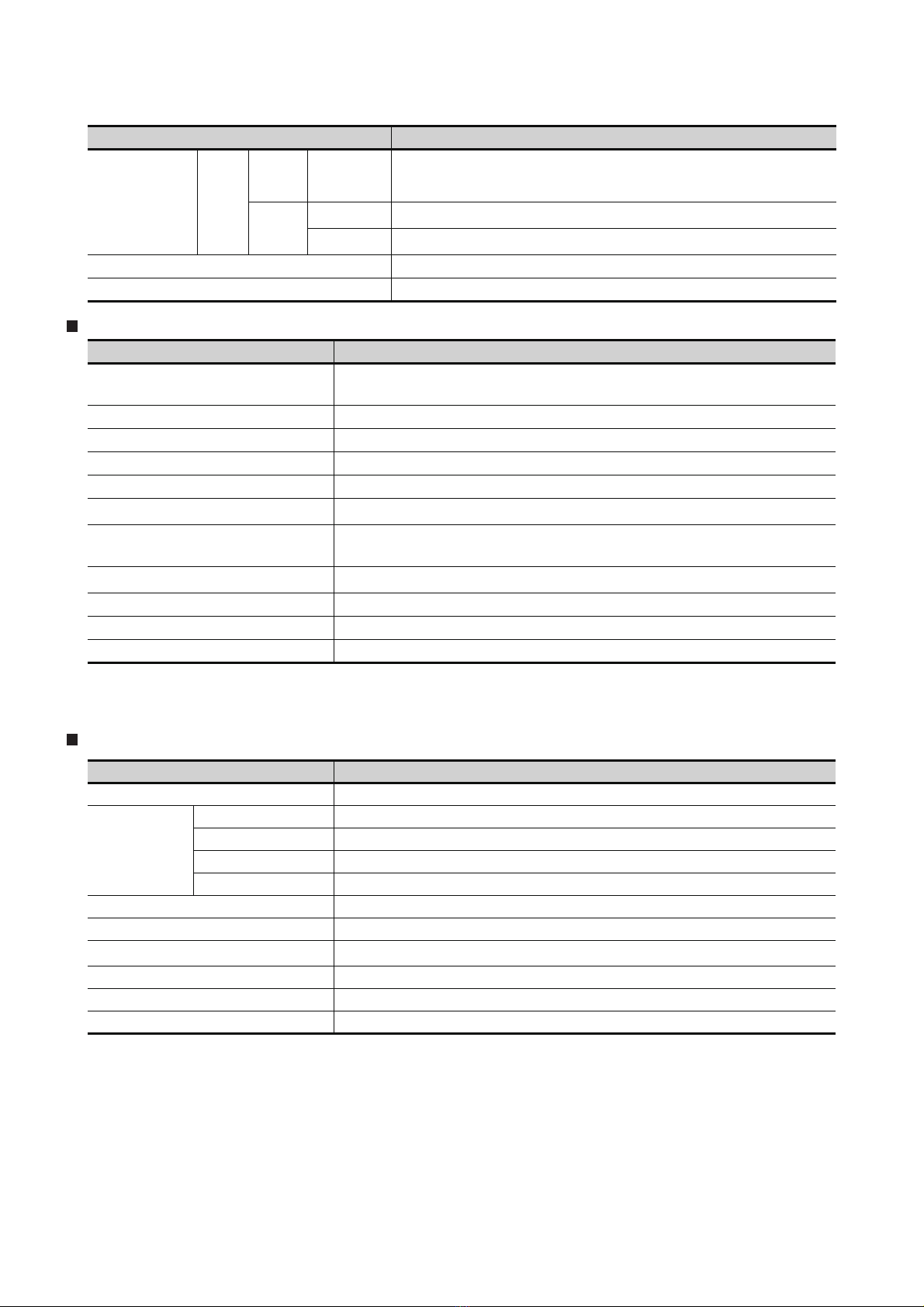
ABBREVIATIONS AND GENERIC TERMS
Abbreviations and generic terms used in this manual are as follows:
GOT
Abbreviations and generic terms Description
GT SoftGOT1000 Abbreviation of GT SoftGOT1000
GT1695 GT1695M-X Abbreviation of GT1695M-XTBA, GT1695M-XTBD
GT1685 GT1685M-S Abbreviation of GT1685M-STBA, GT1685M-STBD
GT1675M-S Abbreviation of GT1675M-STBA, GT1675M-STBD
GT1675
GT1672 GT1672-VN Abbreviation of GT1672-VNBA, GT1672-VNBD
GT1665
GT1662 GT1662-VN Abbreviation of GT1662-VNBA, GT1662-VNBD
GT1655 GT1655-V Abbreviation of GT1655-VTBD
GT1 6
GT1595 GT1595-X Abbreviation of GT1595-XTBA, GT1595-XTBD
GT1585
GT1 57
GOT1000 Series
GT1 56
GT1 55
GT1 5
GT11 5
GT11
GT1 05
GT1 04
GT1030
GT1020
GT1 0
GT1675M-V Abbreviation of GT1675M-VTBA, GT1675M-VTBD
GT1675-VN Abbreviation of GT1675-VNBA, GT1675-VNBD
GT1665M-S Abbreviation of GT1665M-STBA, GT1665M-STBD
GT1665M-V Abbreviation of GT1665M-VTBA, GT1665M-VTBD
Abbreviation of GT1695, GT1685, GT1675, GT1672, GT1665, GT1662, GT1655,
GT16 Handy GOT
GT1585V-S Abbreviation of GT1585V-STBA, GT1585V-STBD
GT1585-S Abbreviation of GT1585-STBA, GT1585-STBD
GT1575V-S Abbreviation of GT1575V-STBA, GT1575V-STBD
GT1575-S Abbreviation of GT1575-STBA, GT1575-STBD
GT1575-V Abbreviation of GT1575-VTBA, GT1575-VTBD
GT1575-VN Abbreviation of GT1575-VNBA, GT1575-VNBD
GT1572-VN Abbreviation of GT1572-VNBA, GT1572-VNBD
GT1565-V Abbreviation of GT1565-VTBA, GT1565-VTBD
GT1562-VN Abbreviation of GT1562-VNBA, GT1562-VNBD
GT1555-V Abbreviation of GT1555-VTBD
GT1555-Q Abbreviation of GT1555-QTBD, GT1555-QSBD
GT1550-Q Abbreviation of GT1550-QLBD
Abbreviation of GT1595, GT1585, GT157 , GT156 , GT155
GT11 55-Q
GT1150-Q Abbreviation of GT1150-QLBDQ, GT1150-QLBDA, GT1150-QLBD
GT1055-Q Abbreviation of GT1055-QSBD
GT1050-Q Abbreviation of GT1050-QBBD
GT1045-Q Abbreviation of GT1045-QSBD
GT1040-Q Abbreviation of GT1040-QBBD
Abbreviation of GT1155-QTBDQ, GT1155-QSBDQ, GT1155-QTBDA, GT1155-QSBDA,
GT11 5 5-QT B D, GT11 5 5-QS B D
Abbreviation of GT115 , GT11 Handy GOT
Abbreviation of GT1030-LBD, GT1030-LBD2, GT1030-LBL, GT1030-LBDW, GT1030LBDW2, GT1030-LBLW, GT1030-LWD, GT1030-LWD2, GT1030-LWL, GT1030-LWDW,
GT1030-LWDW2, GT1030-LWLW, GT1030-HBD, GT1030-HBD2, GT1030-HBL, GT1030HBDW, GT1030-HBDW2, GT1030-HBLW, GT1030-HWD, GT1030-HWD2, GT1030-HWL,
GT1030-HWDW, GT1030-HWDW2, GT1030-HWLW
Abbreviation of GT1020-LBD, GT1020-LBD2, GT1020-LBL, GT1020-LBDW, GT1020LBDW2, GT1020-LBLW, GT1020-LWD, GT1020LWD2, GT1020-LWL, GT1020-LWDW,
GT1020-LWDW2, GT1020-LWLW
Abbreviation of GT105 , GT104 , GT1030, GT1020
(Continued to next page)
A - 17
Page 20
Abbreviations and generic terms Description
GT1 6
Handy
GOT1000 Series
GOT900 Series Abbreviation of GOT-A900 series, GOT-F900 series
GOT800 Series Abbreviation of GOT-800 series
Handy
GOT
GOT
GT11
Handy
GOT
GT1665HS-V Abbreviation of GT1665HS-VTBD
GT1155HS-Q Abbreviation of GT1155HS-QSBD
GT1150HS-Q Abbreviation of GT1150HS-QLBD
Communication unit
Abbreviations and generic terms Description
Bus connection unit
Serial communication unit GT15-RS2-9P, GT15-RS4-9S, GT15-RS4-TE
RS-422 conversion unit GT15-RS2T4-9P, GT15-RS2T4-25P
Ethernet communication unit GT15-J71E71-100
MELSECNET/H communication unit GT15-J71LP23-25, GT15-J71BR13
MELSECNET/10 communication unit
CC-Link IE controller network communication
unit
CC-Link communication unit
Interface converter unit GT15-75IF900
Serial multi-drop connection unit GT01-RS4-M
Connection Conversion Adapter GT10-9PT5S
GT15-QBUS, GT15-QBUS2, GT15-ABUS, GT15-ABUS2,
GT15-75QBUSL, GT15-75QBUS2L, GT15-75ABUSL, GT15-75ABUS2L
GT15-75J71LP23-Z*1, GT15-75J71BR13-Z
GT15-J71GP23-SX
GT15-J61BT13, GT15-75J61BT13-Z
*2
*3
*1 A9GT-QJ71LP23 + GT15-75IF900 set
*2 A9GT-QJ71BR13 + GT15-75IF900 set
*3 A8GT-J61BT13 + GT15-75IF900 set
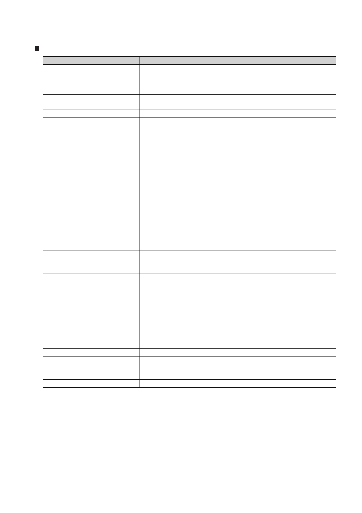
Option unit
Abbreviations and generic terms Description
Printer unit GT15-PRN
Video input unit GT16M-V4, GT15V-75V4
Video/RGB unit
Multimedia unit GT16M-MMR
CF card unit GT15-CFCD
CF card extension unit
External I/O unit GT15-DIO, GT15-DIOR
Sound output unit GT15-SOUT
Fingerprint unit GT15-80FPA
RGB input unit GT16M-R2, GT15V-75R1
Video/RGB input unit GT16M-V4R1, GT15V-75V4R1
RGB output unit GT16M-ROUT, GT15V-75ROUT
*1
GT15-CFEX-C08SET
*1 GT15-CFEX + GT15-CFEXIF + GT15-C08CF set.
A - 18
Page 21
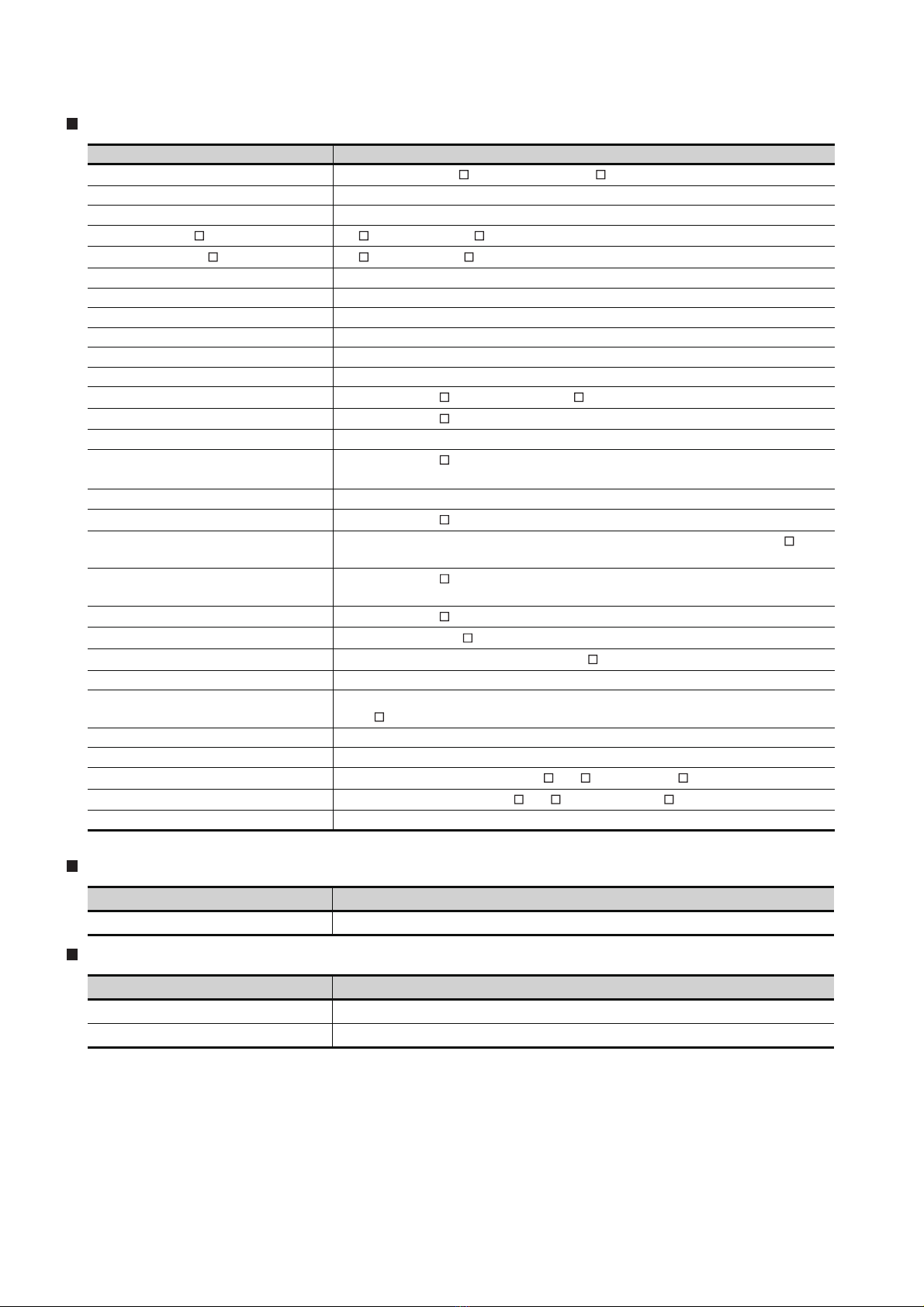
Option
Abbreviations and generic terms Description
GT05-MEM-16MC, GT05-MEM-32MC, GT05-MEM-64MC, GT05-MEM-128MC,
CF card
Memory card adaptor GT05-MEM-ADPC
Option function board
Battery GT15-BAT, GT11-50BAT
Protective Sheet
Protective cover for oil
USB environmental protection cover GT16-UCOV, GT16-50UCOV, GT15-UCOV, GT11-50UCOV
Stan d
Attachment
Backlight
Multi-color display board GT15-XHNB, GT15-VHNB
Connector conversion box GT11H-CNB-37S, GT16H-CNB-42S
Emergency stop sw guard cover GT11H-50ESCOV, GT16H-60ESCOV
Memory loader GT10-LDR
Memory board GT10-50FMB
Panel-mounted USB port extension GT10-C10EXUSB-5S
GT05-MEM-256MC, GT05-MEM-512MC, GT05-MEM-1GC, GT05-MEM-2GC,
GT05-MEM-4GC, GT05-MEM-8GC, GT05-MEM-16GC
GT16-MESB, GT15-FNB, GT15-QFNB, GT15-QFNB16M,
GT15-QFNB32M, GT15-QFNB48M, GT15-MESB48M, GT11-50FNB
GT16-90PSCB, GT16-90PSGB, GT16-90PSCW, GT16-90PSGW,
GT16-80PSCB, GT16-80PSGB, GT16-80PSCW, GT16-80PSGW,
GT16-70PSCB, GT16-70PSGB, GT16-70PSCW, GT16-70PSGW,
For GT16
For GT15
For GT11
For GT10
GT05-90PCO, GT05-80PCO, GT05-70PCO, GT05-60PCO,
GT05-50PCO, GT16-50PCO, GT10-40PCO, GT10-30PCO,
GT10-20PCO
GT15-90STAND, GT15-80STAND, GT15-70STAND, A9GT-50STAND,
GT05-50STAND
GT15-70ATT-98, GT15-70ATT-87, GT15-60ATT-97, GT15-60ATT-96,
GT15-60ATT-87, GT15-60ATT-77, GT15-50ATT-95W, GT15-50ATT-85
GT16-90XLTT, GT16-80SLTT, GT16-70VLTN, GT16-60VLTN,
GT15-90XLTT, GT15-80SLTT, GT16-70SLTT, GT16-70VLTT,
GT16-60SLTT, GT16-60VLTT, GT15-70SLTT, GT15-70VLTT,
GT15-70VLTN, GT15-60VLTT, GT15-60VLTN
GT16-60PSCB, GT16-60PSGB, GT16-60PSCW, GT16-60PSGW,
GT16-50PSCB, GT16-50PSGB, GT16-50PSCW, GT16-50PSGW,
GT16-90PSCB-012, GT16-80PSCB-012, GT16-70PSCB-012,
GT16-60PSCB-012, GT16-50PSCB-012, GT16H-60PSC
GT15-90PSCB, GT15-90PSGB, GT15-90PSCW, GT15-90PSGW,
GT15-80PSCB, GT15-80PSGB, GT15-80PSCW, GT15-80PSGW,
GT15-70PSCB, GT15-70PSGB, GT15-70PSCW, GT15-70PSGW,
GT15-60PSCB, GT15-60PSGB, GT15-60PSCW, GT15-60PSGW,
GT15-50PSCB, GT15-50PSGB, GT15-50PSCW, GT15-50PSGW
GT11-50PSCB, GT11-50PSGB, GT11-50PSCW, GT11-50PSGW,
GT11H-50PSC
GT10-50PSCB, GT10-50PSGB, GT10-50PSCW, GT10-50PSGW,
GT10-40PSCB, GT10-40PSGB, GT10-40PSCW, GT10-40PSGW,
GT10-30PSCB, GT10-30PSGB, GT10-30PSCW, GT10-30PSGW,
GT10-20PSCB, GT10-20PSGB, GT10-20PSCW, GT10-20PSGW
A - 19
Page 22
Software
Abbreviations and generic terms Description
GT W orks 3
GT Designer3 Abbreviation of screen drawing software GT Designer3 for GOT1000 series
GT Simulator3 Abbreviation of screen simulator GT Simulator3 for GOT1000/GOT900 series
GT Works2 Version SW D5C-GTWK2-E, SW D5C-GTWK2-EV
GT Designer2 Version SW D5C-GTD2-E, SW D5C-GTD2-EV
GT Designer2 Abbreviation of screen drawing software GT Designer2 for GOT1000/GOT900 series
GT Converter2 Abbreviation of data conversion software GT Converter2 for GOT1000/GOT900 series
GT Designer2 Classic Abbreviation of screen drawing software GT Designer2 Classic for GOT900 series
GT Simulator2 Abbreviation of screen simulator GT Simulator 2 for GOT1000 / GOT900 series
GT SoftGOT1000 Abbreviation of monitoring software GT SoftGOT1000
GT SoftGOT2 Abbreviation of monitoring software GT SoftGOT2
GX Developer
GX LogViewer
GX Simulator2 Abbreviation of GX Works2 with the simulation function
GX Simulator
Document Converter Abbreviation of document data conversion software Document Converter for GOT1000 series
PX Developer
MT Works2
MT Developer
MR Configurator2
MR Configurator
FR Configurator
NC Configurator Abbreviation of CNC parameter setting support tool NC Configurator
FX Configurator-FP
FX3U-ENET-L Configuration tool Abbreviation of FX3U-ENET-L type Ethernet module setting software (SW1D5-FXENETL-E)
RT ToolBox2 Abbreviation of robot program creation software (3D-11C-WINE)
MX Component
MX Sheet
LCPU Logging Configuration Tool Abbreviation of LCPU Logging Configuration Tool (SW1DNN-LLUTL-E)
Abbreviation of the SW DNC-GTWK3-E and SW DNC-GTWK3-EA
Abbreviation of SW D5C-GPPW-E(-EV)/SW D5F-GPPW-E type software package
Abbreviation of SW DNN-VIEWER-E type software package
Abbreviation of SW D5C-LLT-E(-EV) type ladder logic test tool function software packages
(SW5D5C-LLT (-EV) or later versions)
Abbreviation of SW D5C-FBDQ-E type FBD software package for process control
Abbreviation of motion controller engineering environment MELSOFT MT Works2 (SW DNCMTW2-E)
Abbreviation of SW RNC-GSV type general start-up support software for motion controller Q
series
Abbreviation of SW DNC-MRC2-E type Servo Configuration Software
Abbreviation of MRZJW -SETUP type servo set up software
Abbreviation of Inverter Setup Software (FR-SW -SETUP-WE)
Abbreviation of parameter setting, monitoring, and testing software packages for FX3U-20SSC-
H (SW D5C-FXSSC-E)
Abbreviation of MX Component Version (SW D5C-ACT-E, SW D5C-ACT-EA)
Abbreviation of MX Sheet Version (SW D5C-SHEET-E, SW D5C-SHEET-EA)
License key (for GT SoftGOT1000)
Abbreviations and generic terms Description
License GT15-SGTKEY-U, GT15-SGTKEY-P
License key (for GT SoftGOT2)
Abbreviations and generic terms Description
License key A9GTSOFT-LKEY-P (For DOS/V PC)
License key FD SW5D5F-SGLKEY-J (For PC CPU module)
A - 20
Page 23

Others
Abbreviations and generic terms Description
IAI ROBOT CONTROLLER Abbreviation of robot controller manufactured by IAI Corporation
OMRON PLC Abbreviation of PLC manufactured by OMRON Corporation
KEYENCE PLC Abbreviation of PLC manufactured by KEYENCE CORPORATION
KOYO EI PLC Abbreviation of PLC manufactured by KOYO ELECTRONICS INDUSTRIES CO., LTD.
SHARP PLC Abbreviation of PLC manufactured by Sharp Manufacturing Systems Corporation
JTEKT PLC Abbreviation of PLC manufactured by JTEKT Corporation
TOSHIBA PLC Abbreviation of PLC manufactured by TOSHIBA CORPORATION
TOSHIBA MACHINE PLC Abbreviation of PLC manufactured by TOSHIBA MACHINE CO., LTD.
HITACHI IES PLC Abbreviation of PLC manufactured by Hitachi Industrial Equipment Systems Co., Ltd.
HITACHI PLC Abbreviation of PLC manufactured by Hitachi, Ltd.
FUJI FA PLC Abbreviation of PLC manufactured by Fuji Electric FA Components & Systems Co., Ltd.
PANASONIC SERVO AMPLIFIER Abbreviation of servo amplifier manufactured by Panasonic Corporation
PANASONIC EW PLC Abbreviation of PLC manufactured by Panasonic Electric Works Co., Ltd.
YASKAWA PLC Abbreviation of PLC manufactured by YASKAWA Electric Corporation
YOKOGAWA PLC Abbreviation of PLC manufactured by Yokogawa Electric Corporation
ALLEN-BRADLEY PLC Abbreviation of Allen-Bradley PLC manufactured by Rockwell Automation, Inc.
GE FANUC PLC Abbreviation of PLC manufactured by GE Fanuc Automation Corporation
LS IS PLC Abbreviation of PLC manufactured by LS Industrial Systems Co., Ltd.
SCHNEIDER PLC Abbreviation of PLC manufactured by Schneider Electric SA
SICK SAFETY CONTROLLER Abbreviation of safety controller manufactured by SICK AG
SIEMENS PLC Abbreviation of PLC manufactured by Siemens AG
OMRON temperature
controller
SHINKO indicating
controller
CHINO controller Abbreviation of temperature controller manufactured by CHINO CORPORATION
Temperature
controller
HIRATA HNC controller Abbreviation of HNC controller manufactured by Hirata Corporation
PC CPU module Abbreviation of PC CPU Unit manufactured by CONTEC CO., LTD
GOT (server) Abbreviation of GOTs that use the server function
GOT (client) Abbreviation of GOTs that use the client function
FUJI SYS temperature
controller
YAMATAKE temperature
controller
YOKOGAWA temperature
controller
RKC temperature
controller
Abbreviation of temperature controller manufactured by OMRON Corporation
Abbreviation of temperature controller manufactured by Shinko Technos Co., Ltd.
Abbreviation of temperature controller manufactured by Fuji Electric Systems Co., Ltd.
Abbreviation of temperature controller manufactured by Yamatake Corporation
Abbreviation of temperature controller manufactured by Yokogawa Electric Corporation
Abbreviation of temperature controller manufactured by RKC INSTRUMENT INC.
Windows font
Intelligent function module
MODBUS /RTU
MODBUS /TCP
Abbreviation of TrueType font and OpenType font available for Windows
(Differs from the True Type fonts settable with GT Designer2)
Indicates the modules other than the PLC CPU, power supply module and I/O module that are
mounted to the base unit.
Generic term for protocols designed to use MODBUS protocol messages on a serial
communication.
Generic term for the protocol designed to use MODBUS protocol messages on a TCP/IP
network.
A - 21
Page 24
HOW TO READ THIS MANUAL
1 Functions
This manual describes functions available for the GT Designer2 Version 2.96A, GT Designer3
Version1.28E.
For the added functions by the product version upgrade, refer to the list of functions added by GT
Designer2 version upgrade in Appendices.
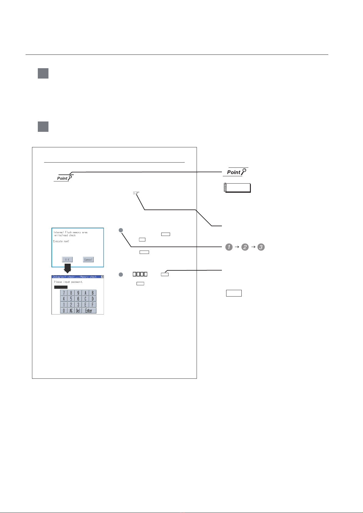
2 Symbols
Following symbols are used in this manual.
13.3.3 Memory check operation
Carries out write/read check of memory.
When drive is not displayed
When the drive (memory) to check is not displayed, confirm the moun ting procedure
or memory type with reference to the following.
• CF card inser ting/removing method Section 7.1 CF Card
When no faults are found in mounting , etc, a memory failure may be arosen.
Replace the CF card or Flash memory.
For details of Flash memory, contact your nearest sales office or FA Center.
The following example explains about Memo ry Check using Flash memory.
For the CF card memory check, install the CF card before carrying out the same key operations as built-in
flash memory.
1 Select [Flash M emory] in the Memory check
setting screen, and touch the button.
If select the button, the nume ric keyboard
OK
window is displayed.
If select the button, the screen returns
Cancel
to the initial menu.
Check
Refers to the information
required.
Remark
Refers to the supplementary
explanations for reference.
Indicates the items in which the detailed
explanation is described (manual, chapter,
section, item of the manual).
. . . .
Indicates the operation steps.
13.3 Memory Check
13 - 4
13.3.3 Memory check operation
5 9 2 0
2 Touch and then .
3 (The password is fixed to 5920.)
4 Touching executes read/write check for
Enter
the flash memory.
Enter
Menu and items are differentiated with
parentheses.
[ ]
: refers to the menu of GOT utility.
: refers to the button in the dialog
box of GOT utility.
A - 22
Page 25
1. OVERVIEW
1
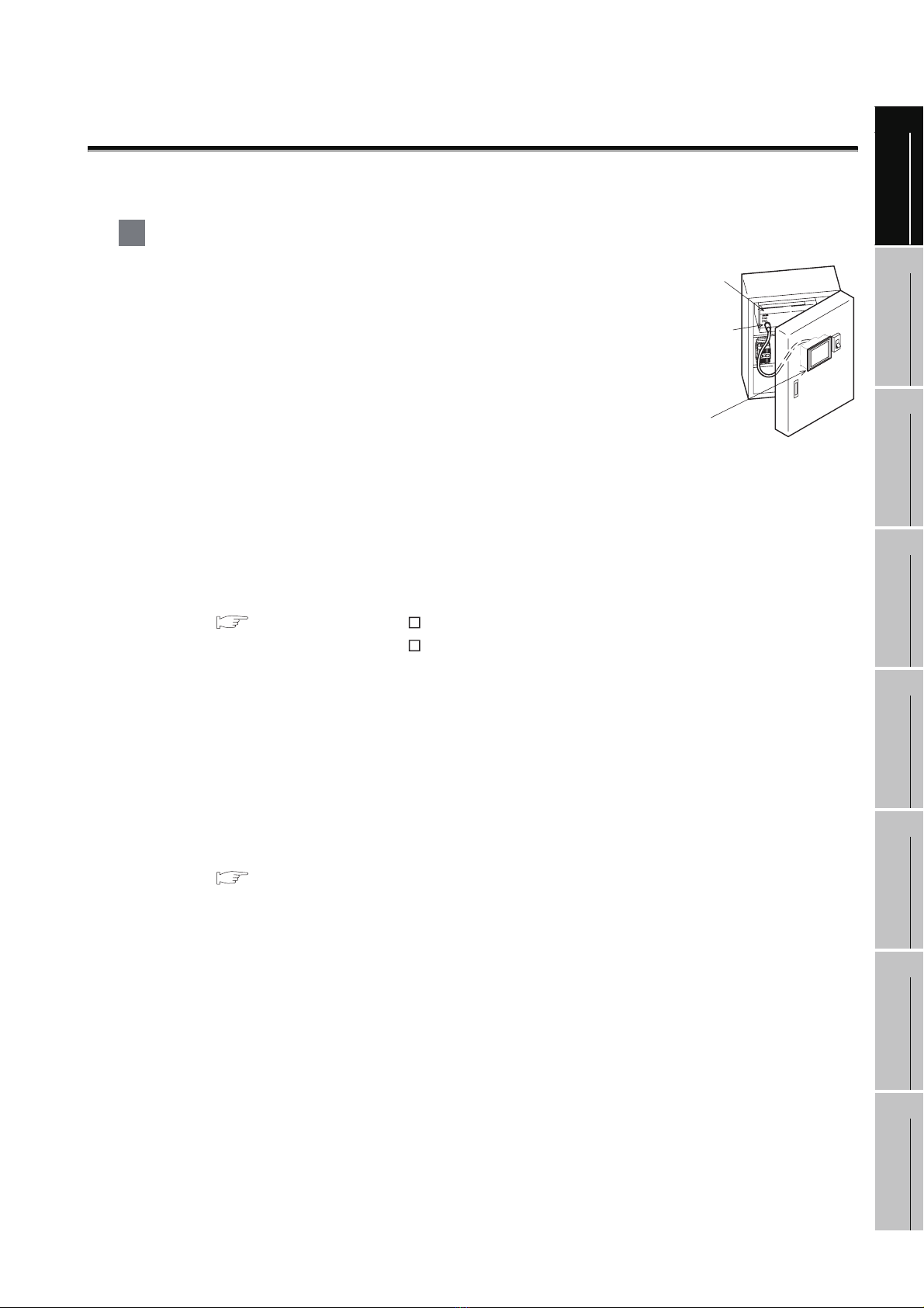
1 About GOT
A GOT is installed on the panel surface of a control panel or operating
panel and connects to the PLC within the control panel. The GOT
carries out switch operation, lamp display, data display, message
display, etc.
For the display screen, two kinds of screens are available : user screen
and utility screen.
(1) User screen
The user screen is a screen drawn by drawing software.
The objects [Touch switch], [Lamp display], [Comment display], and [Numeric display] can be
arbitrarily arranged on the display.
A "horizontal format" or "vertical format" may be selected for displaying a user’s project.
Moreover, multiple screens created within drawing software can be individually selected or
overlapped for the display.
For details, refer to the following.
GT Designer2 Version Basic Operation/Data Transfer Manual
GT Designer2 Version Screen Design Manual
GT Designer3 Version1 Screen Design Manual
(2) Utility Screen
The utility screen is a factory drawn horizontal screen that cannot be edited.
Installing the BootOS or Standard monitor OS in the GOT from drawing software, the utility screen
is displayed.
The utility screen has options for [Brightness/contrast], [Memory check], etc, and the format is
horizontal only.
For details, refer to the following.
PLC
Connector for
program
GOT
OVERVIEW
2
SYSTEM
CONFIGURATION
3
SPECIFICATIONS
4
PAR T NA M E
5
EMC DIRECTIVE
6
Chapter 9 to Chapter 15
INSTALLATION
7
WIRING
8
OPTION
1 - 1
Page 26
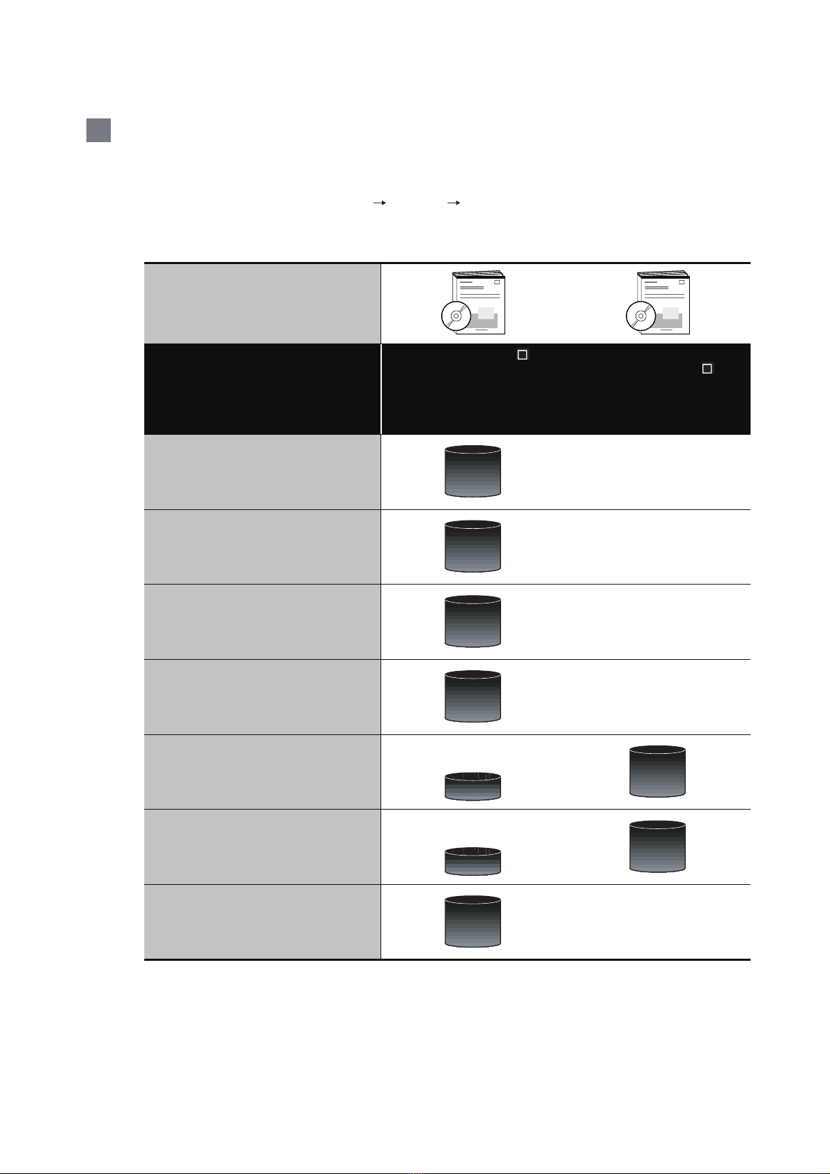
2 About Manual
The following manuals related to GOT 1000 series are available. Refer to each manual in accordance
with the intended use.
(1) Installation of the software programs Drawing Data transfer
For operations from creating project data to transferring data to GOT, refer to the following
manuals.
GT Designer2 Version
GT Designer2 Version
Screen Design Manual
GT Designer3 Version1
Screen Design Manual (Functions)
Purpose
Basic Operation/Data Transfer
GT Designer3 Version1
Screen Design Manual
(Fundamentals)
Manual
*1
*1
*1
*1
Installing product on PC
Creating projects
Creating screens
Drawing figures
Making Common Settings
Placing/Setting objects
Detailed
Detailed
Detailed
Detailed
Detailed
Overview
Detailed
Overview
1 - 2
Transferring data to GOT
*1 Stored in the GT Works 2/GT Designer2/GT Works 3/GT Designer3 in PDF format.
Detailed
Page 27
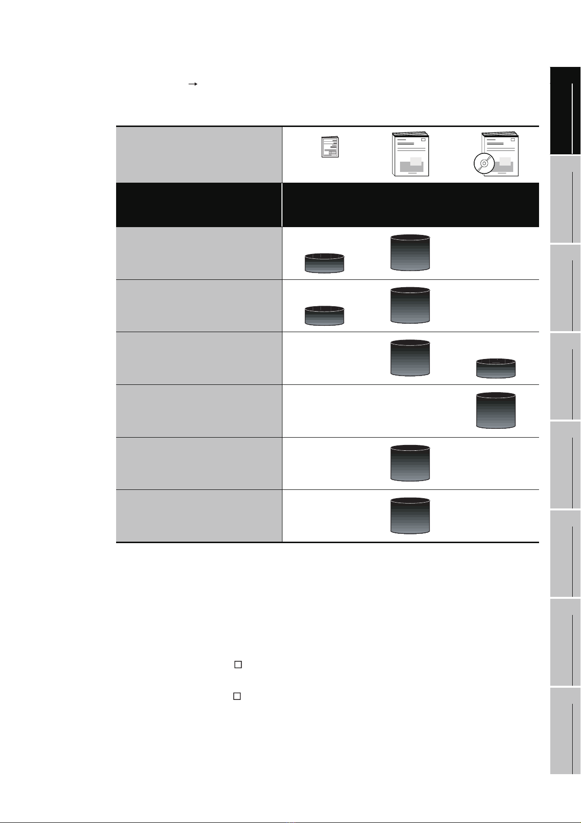
(2) Installing a GOT connection to a PLC
For the operations from installing a GOT to communicating with a PLC CPU, refer to the following
manuals.
1
OVERVIEW
Purpose
Confirming part names and
specifications of the GOT
Confirming the GOT installation
method
Confirming the mounting method for
communication units or option
devices
Confirming the PLC connection
method
(Included)
GT1 5 Ge n era l
Description
GT11 General
Description
Overview
Overview
GT15 User's Manual
GT11 U ser ' s M a nua l
Detailed
Detailed
Detailed
GOT1000 Series
Connection Manual
Overview
Detailed
2
*1
SYSTEM
CONFIGURATION
3
SPECIFICATIONS
4
PAR T NA M E
5
Confirming the utility operation
method
Detailed
Confirming error codes (system
alarm) displayed on the GOT
*1 Stored in the GT Works2/GT Designer2/GT Works 3/GT Designer3 in PDF format.
Detailed
(3) Other manuals
The following manuals are also available.
The following manuals are stored in the GT Works2/GT Designer2/GT Works3/GT Designer3 in
PDF format.
(a) GOT1000 Series Gateway Functions Manual
Describes how to use the gateway function.
(b) GT Simulator 2 Version Operation Manual
Describes how to simulate the created project data with GT Simulator2.
(c) GT Converter2 Version Operating Manual
Describes how to use the GT Converter2.
EMC DIRECTIVE
6
INSTALLATION
7
WIRING
8
1 - 3
OPTION
Page 28

1.1 Features
(1) Improved monitoring performance and connectivity to FA devices
• Multiple languages are displayed using the Unicode2.1-compatible fonts and beautiful characters
are drawn using the TrueType and high quality fonts.
• Two types of display modes are provided: 256-color display and monochrome display.
In the monochrome display, 16 scales are used to improve the display.
• High-speed monitoring through high-speed serial communication at maximum tare of 115.2 kbps
or through bus connection with the PLC.
• High speed display and high speed touch switch response.
(2) More efficient GOT operations including screen design, startup, adjustment, management and
maintenance works
• The 3MB user memory is included as standard.
• CF card interface is included as standard.
• The USB connector is positioned on the GOT front. This enables the system startup to be
performed more efficiently using FA device setup tool, and eliminates the indirect works (opening
and closing the control panel, cable replacement, cable rewiring) in order to improve the working
efficiency.
(3) Enhanced support of FA setup tools
• PLC program transfer and monitoring are possible via the personal computer that is connected to
the GOT if connected directly to the A, QnA, L, Q, or FX series of the PLC CPU (FA transparent
function).
1 - 4
1.1 Features
Page 29
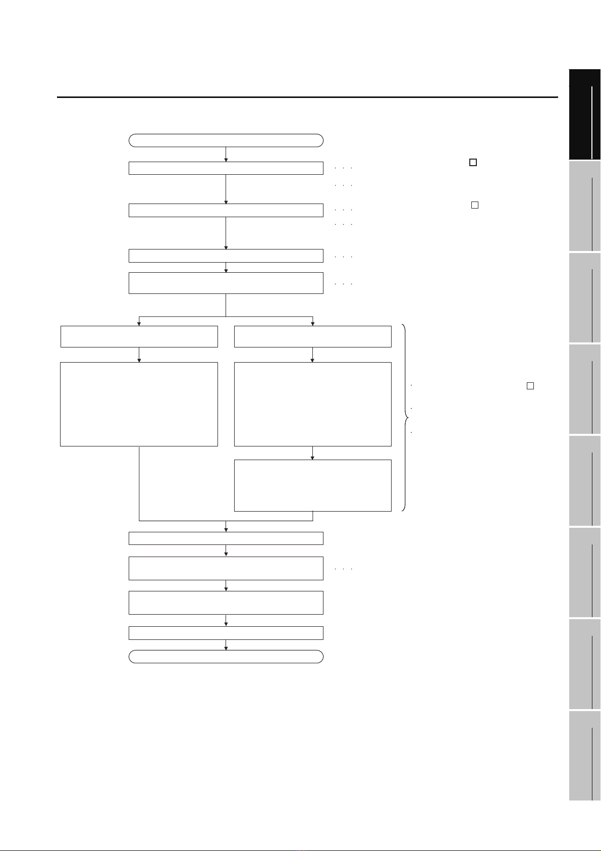
1.2 Rough Pre-operation Procedure
The outline procedure before operating GOT is shown.
Start
Install GT Designer2 or GT Designer3 in the PC.
Create project data.
Wire for the GOT power supply.
Attach the option function board.
(Only when necessary)
When transferring data via a cable When transferring data via the CF card
Refer to GT Designer2 Version
Basic Operation/Data Transfer Manual.
Refer to GT Designer3 Version1
Screen Design Manual(Fundamentals)
Refer to GT Designer2 Version
Screen Design Manual.
Refer to GT Designer3 Version1
Screen Design Manual(Functions)
or Help functions of GT Designer.
Refer to Chapter 7 WIRING.
Refer to Chapter 8 OPTION.
1
2
SYSTEM
3
OVERVIEW
CONFIGURATION
Connect GOT and PC with a USB cable
or RS-232 cable.
Install and download the OS program,
project data installed in the PC to the GOT.
1) Install the standard monitor OS,
communication driver, extended
functions OS, option OS to GOT.
2) Download the project data created
by the PC.
Check the communication settings.
Connect the cable to GOT and the destination
connector.
Turn on the GOT power and the system of the
connection destination.
Insert the CF card in the PC.
Write the OS, project data installed
in the PC in the CF card.
1) Write the standard monitor OS,
communication driver, extended function
OS, option OS in the CF card.
2) Write the project data created
by the PC in the CF card.
Install the CF card to GOT to install
and download the standard monitor OS,
communication driver, extended
function OS, option OS, project data
to the built-in flash memory.
Refer to GOT1000 Series Connection Manual.
Refer to GT Designer2 Version
Basic Operation/Data Transfer Manual.
Refer to GT Designer3 Version1
Screen Design Manual(Fundamentals)
Refer to 16. INSTALLATION OF
core OS, BOOTOS AND STANDARD
MONITOR OS in this manual for the
operations of GOT.
SPECIFICATIONS
4
PAR T NA M E
5
EMC DIRECTIVE
6
INSTALLATION
Start the monitor. (Display each screen.)
End
1.2 Rough Pre-operation Procedure
7
WIRING
8
OPTION
1 - 5
Page 30
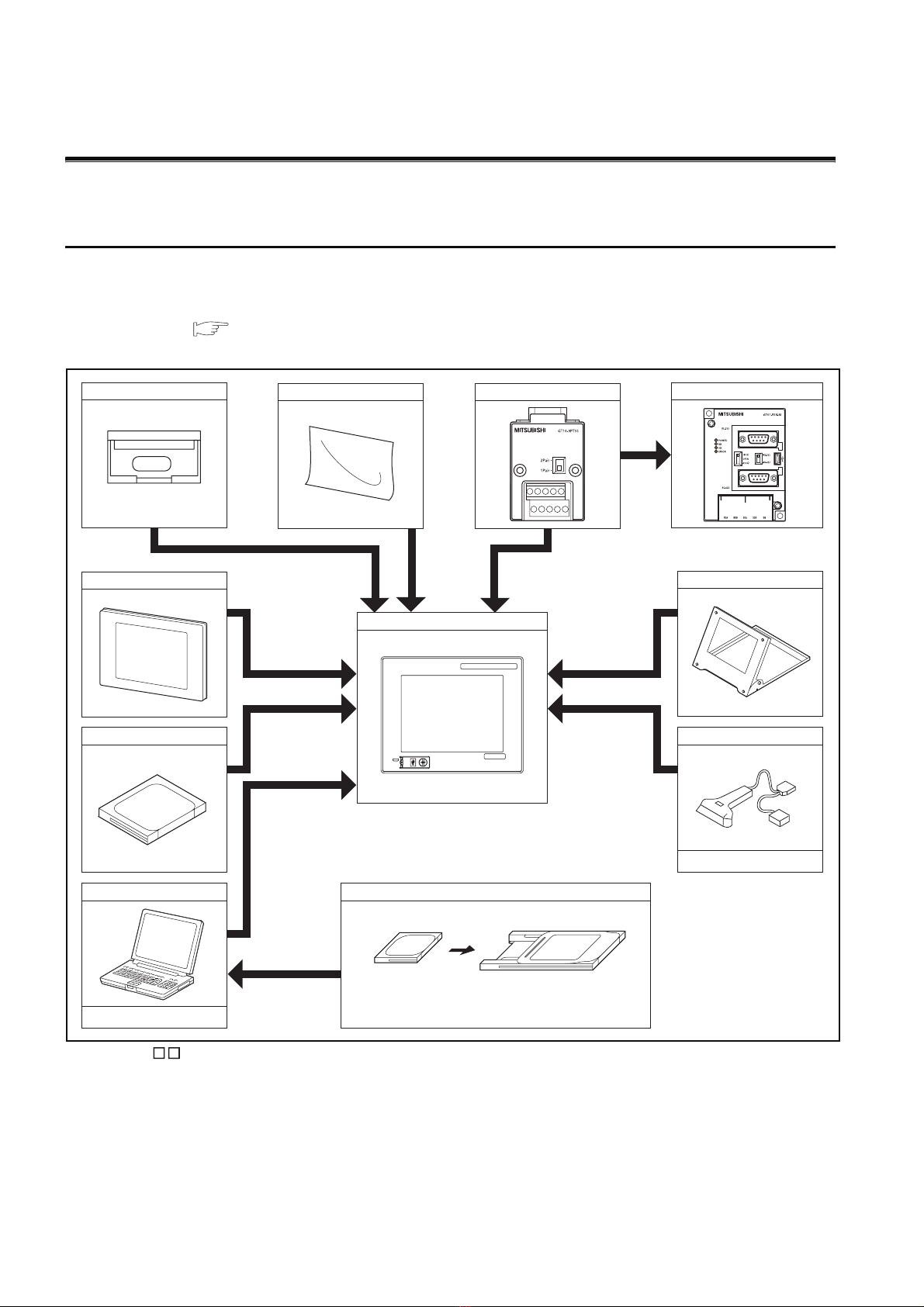
2. SYSTEM CONFIGURATION
2.1 Overall Configuration
The overall configuration of GOT is as follows.
For the connection methods applicable to GOT1000 series and cable, refer to the following.
GOT1000 Series Connection Manual
Option function board
Protective cover for oil
CF card
Protective sheet
Connector conversion adapter
GOT
GRAPHIC OPERATION TERMINAL
GOT
1000
MITSUBISHI
Serial multi-drop connection unit
Stand
Bar code reader, RFID
Personal computer
Commercially available
• GT11 does not connect a printer.
2 - 1
2.1 Overall Configuration
Commercially available
Memory card
CF card Memory card adaptor
Page 31

2.2 Component List
(1) Explanation of the GOT model name
1
G T 1 1 5 5
Communication
interface
Power type
Panel color type
Display device type
Resolution
Display color type
Screen size type
GOT 1000 series GT15/GT11/GT10
*1: For GT15 that can display 65536 colors, refer to following.
GT15 User's Manual
2 : Built-in RS-232
Q : Built-in Q bus
A : Built-in A bus
Blank : Built-in RS-422
A : 100 to 240VAC
D : 24VDC
L : 5VDC
B : Black
W : White
T : TFT color (High intensity, wide angle view)
N : TFT color
S : STN color
L : STN monochrome (black and white)
B : STN monochrome (blue and white)
H : STN monochrome (black and white, high contrast)
X : 1024 768 (XGA)
S : 800 600 (SVGA)
V : 640 480 (VCA)
Q : 320 240 (QVGA)
Blank: less than 320 240
5 : 65535/256 colors*
2 : 16 colors
0 : Monochrome (black and white) 16 scales
9 : 15.0"
8 : 12.1"
7 : 10.4"
6 : 8.4"
5 : 5.7"
4 : 4.7"
3 : 4.5"
2 : 3.7"
1
OVERVIEW
2
SYSTEM
CONFIGURATION
3
SPECIFICATIONS
4
PAR T NA M E
5
EMC DIRECTIVE
6
2.2 Component List
INSTALLATION
7
WIRING
8
OPTION
2 - 2
Page 32

(2) Explanation of the option model name
GT
90 : 15.0"
80 : 12.1"
75 : Common for 10.4", 8.4"
70 : Dedicated for 10.4"
60 : Dedicated for 8.4"
50 : Dedicated for 5.7"
40 : Dedicated for 4.7"
30 : Dedicated for 4.5"
20 : Dedicated for 3.7"
15 : Dedicated for GT15*
11 : Dedicated for GT11*
10 : Dedicated for GT10*
09 :
05 :
Common for GT15/GT11*
01 :
*1: There are optional components common for GT15, GT11 and GT10.
1
1
1
1
2 - 3
2.2 Component List
Page 33

2.2.1 GOT (GT11)
1 Models with a built-in serial interface
1
5.7" [320 x 240 dots], TFT color liquid crystal, 256 colors, 24VDC, memory size 3MB, built-
in battery, built-in serial interface
5.7" [320 x 240 dots], STN color liquid crystal, 256 colors, 24VDC, memory size 3MB, built-
in battery, built-in serial interface
5.7" [320 x 240 dots], STN monochrome liquid crystal, monochrome (black/white), 16
scales, 24VDC, memory size 3MB, built-in battery, built-in serial interface
GOT
GT1155-QT BD
GT1155-QSBD
GT1150-QLBD
2 Models with a built-in bus interface
GT1155-QT BDQ
GT1155-QT BDA
GT1155-QSBDQ
GOT
GT1155-QSBDA
GT1150-QLBDQ
GT1150-QLBDA
5.7" [320 x 240 dots], TFT color liquid crystal, 256 colors, 24VDC, memory size 3MB, built-
in battery, built-in Q bus/serial interface
5.7" [320 x 240 dots], TFT color liquid crystal, 256 colors, 24VDC, memory size 3MB, built-
in battery, built-in A bus/serial interface
5.7" [320 x 240 dots], STN color liquid crystal, 256 colors, 24VDC, memory size 3MB, built-
in battery, built-in Q bus/serial interface
5.7" [320 x 240 dots], STN color liquid crystal, 256 colors, 24VDC, memory size 3MB, built-
in battery, built-in A bus/serial interface
5.7" [320 x 240 dots], STN monochrome liquid crystal, monochrome (black/white), 16
scales, 24VDC, memory size 3MB, built-in battery, built-in Q bus/serial interface
5.7" [320 x 240 dots], STN monochrome liquid crystal, monochrome (black/white), 16
scales, 24VDC, memory size 3MB, built-in battery, built-in A bus/serial interface
2
SYSTEM
3
4
5
OVERVIEW
CONFIGURATION
SPECIFICATIONS
PAR T NA M E
2.2 Component List
2.2.1 GOT (GT11)
EMC DIRECTIVE
6
INSTALLATION
7
WIRING
8
OPTION
2 - 4
Page 34

2.2.2 Option (Optional components for GT11)
PLC connection cable (Sold separately)
Product name Model name Cable length Contents
RS-422
Cable
RS-232
Cable
FXCPU
direct
connection
cable
FX
expansion
board
connection
cable
QnA/A/
FXCPU
direct
connection
cable
computer
link
connection
cable
Computer
link
connection
cable
QCPU
direct
connection
cable
FX
expansion
board
connection,
FX special
adaptor
connection,
data
transfer
cable
FX special
adaptor
connection
Computer
link
connection
cable
*1: Description in parentheses indicates the cable side connector shape.
GT01-C10R4-8P 1m
GT01-C30R4-8P 3m
GT01-C100R4-8P 10m
GT01-C200R4-8P 20m
GT01-C300R4-8P 30m
GT01-C30R4-25P 3m
GT01-C100R4-25P 10m
GT01-C200R4-25P 20m
GT01-C300R4-25P 30m
GT09-C30R4-6C 3m
GT09-C100R4-6C 10m
GT09-C200R4-6C 20m
GT09-C300R4-6C 30m
GT01-C30R2-6P 3m
GT01-C30R2-9S 3m
GT01-C30R2-25P 3m
GT09-C30R2-9P 3m
GT09-C30R2-25P 3m
For connecting FXCPU (MINI DIN 8 pins) and
GOT.
For connecting FXCPU expansion board (MINI
DIN 8 pins) and GOT.
For connecting QnA/ACPU/Motion controller
CPU (A series) FXCPU (D-sub 25 pins) and
GOT.
For connecting FA-CNV
For connecting serial communication unit
(AJ71QC24(N)-R4) and GOT
For connecting computer link unit/serial
communication unit and GOT
For connecting QCPU/Motion controller CPU (Q
series) and GOT
For connecting FXCPU expansion board (D-sub
9pins), special adapter (D-sub 9 pins) and GOT.
For connecting personal computer (GT
Designer2) (D-sub 9 pins: female)
(D-sub 9 pins: female)*1
For connecting FXCPU special adaptor (D-sub
25 pins) and GOT.
For connecting computer link unit/serial
communication unit and GOT
CBL and GOT
*1
and GOT
2 - 5
2.2 Component List
2.2.2 Option (Optional components for GT11)
Page 35

Bus cable for connection to QCPU (Q mode) (Sold separately)
Product name Model name Cable length Description
GT15-QC06B 0.6m
Q add-on cable
Inter-GOT connection
cable
Long Q connection
cable
Long inter-GOT
connection cable
GT15-QC12B 1.2m
GT15-QC30B 3m
GT15-QC50B 5m
GT15-QC100B 10m
GT15-QC150BS 15m
GT15-QC200BS 20m
GT15-QC250BS 25m
GT15-QC300BS 30m
GT15-QC350BS 35m
For connecting QCPU and GOT
For interconnecting GOTs
For connecting QCPU and GOT over a
distance of 13.2 m or farther (Requires A9GT-
QCNB)
For interconnecting GOTs over a distance of
13.2 m or farther
Bus cable for connection to QnA/ACPU/motion controller (A series) (sold separately)
Product name Model name Cable length Description
GT15-A1SC07B 0.7m
For connecting QnAS/AnSCPU/motion
controller CPU (A series) and GOT
For connecting QnAS/AnSCPU/motion
controller CPU (A series) and A7GT-CNB
For connecting QnA/ACPU/motion controller
CPU (A series/expanded base) and GOT
For connecting QnA/ACPU/motion controller
CPU (A series/expanded base) and A7GT-CNB
For connecting motion controller CPU (A series/
basic base) and GOT
For connecting motion controller CPU (A series/
basic base) and A7GT-CNB
Small-CPU
connection cable
Inter-GOT
connection cable
Large-CPU
connection cable
GT15-A1SC12B 1.2m
GT15-A1SC30B 3m
GT15-A1SC50B 5m For connecting QnAS/AnSCPU and GOT
GT15-A1SC05NB 0.45m
GT15-A1SC07NB 0.7m
GT15-A1SC30NB 3m
GT15-A1SC50NB 5m For connecting QnAS/AnSCPU and A7GT-CNB
GT15-C12NB 1.2m
GT15-C30NB 3m
GT15-C50NB 5m
GT15-AC06B 0.6m
GT15-AC12B 1.2m
GT15-AC30B 3m
GT15-AC50B 5m
GT15-A370C12B-S1 1.2m
GT15-A370C25B-S1 2.5m
GT15-A370C12B 1.2m
GT15-A370C25B 2.5m
1
OVERVIEW
2
SYSTEM
CONFIGURATION
3
SPECIFICATIONS
4
PAR T NA M E
5
EMC DIRECTIVE
6
INSTALLATION
7
Small-CPU long
connection cable
GT15-C100EXSS-1 10.6m
GT15-C200EXSS-1 20.6m
GT15-C300EXSS-1 30.6m
For QnAS/AnSCPU/motion controller CPU (A
series) to GOT long distance connection
For A7GT-CNB to GOT long distance
connection Combination of GT15-FXCNB and
GT1 5-C BS
2.2 Component List
2.2.2 Option (Optional components for GT11)
WIRING
8
OPTION
2 - 6
Page 36

Product name Model name Cable length Description
GT15-C07BS 0.7m
GT15-C12BS 1.2m
Long inter-GOT
connection cable
A0J2HCPU
connection cable
Buffer circuit cable GT15-EXCNB 0.5m
GT15-C30BS 3m
GT15-C50BS 5m
GT15-C100BS 10m
GT15-C200BS 20m
GT15-C300BS 30m
GT15-J2C10B 1m
Connection cables for OMRON PLCs (Sold separately)
Product
name
Model name Cable length Description
GT09-C30R40101-9P 3m
GT09-C100R40101-9P 10m
GT09-C200R40101-9P 20m
GT09-C300R40101-9P 30m
GT09-C30R40102-9P 3m
For connecting GOT to OMRON PLC, serial communication
module, serial communication board
For interconnecting GOTs
For connecting the power supply unit (A0J2-
PW) to GOT
Can be used as a GT15-C EXSS-1 when
used in combination with GT15-C BS
RS-422
cable
RS-232
cable
GT09-C100R40102-9P 10m
GT09-C200R40102-9P 20m
GT09-C300R40102-9P 30m
GT09-C30R40103-5T 3m
GT09-C100R40103-5T 10m
GT09-C200R40103-5T 20m
GT09-C300R40103-5T 30m
GT09-C30R20101-9P 3m
GT09-C30R20102-25P 3m For connecting GOT to OMRON connection cable
GT09-C30R20103-25P 3m For connecting GOT to OMRON rack type host link unit
For connecting GOT to OMRON rack type host link unit,
communication board
For connecting GOT to serial communication board
For connecting GOT to OMRON PLC, serial communication
module, communication board, serial communication board
Connection cables for KEYENCE PLCs (Sold separately)
Product
name
RS-422
cable
RS-232
cable
Model name Cable length Description
GT09-C30R41101-5T 3m
GT09-C100R41101-5T 10m
For connecting GOT to KEYENCE multi-communication unit
GT09-C200R41101-5T 20m
GT09-C300R41101-5T 30m
GT09-C30R21101-6P 3m For connecting GOT to KEYENCE PLC
GT09-C30R21102-9S 3m For connecting GOT to KEYENCE multi-communication unit
GT09-C30R21103-3T 3m For connecting GOT to KEYENCE multi-communication unit
2 - 7
2.2 Component List
2.2.2 Option (Optional components for GT11)
Page 37

Connection cables for JTEKT PLCs (Sold separately)
Product
name
RS-422
cable
RS-232
cable
Model name Cable length Description
GT09-C30R41201-6C 3 m
GT09-C100R41201-6C 10 m
GT09-C200R41201-6C 20 m
GT09-C300R41201-6C 30 m
GT09-C30R21201-25P 3 m For connecting GOT to JTEKT PLC
Connection cables for SHARP PLCs (Sold separately)
Product
name
RS-422
cable
RS-232
cable
Model name Cable length Description
GT09-C30R40601-15P 3m
GT09-C100R40601-15P 10m
GT09-C200R40601-15P 20m
GT09-C300R40601-15P 30m
GT09-C30R40602-15P 3m
GT09-C100R40602-15P 10m
GT09-C200R40602-15P 20m
GT09-C300R40602-15P 30m
GT09-C30R40603-6T 3m
GT09-C100R40603-6T 10m
GT09-C200R40603-6T 20m
GT09-C300R40603-6T 30m
GT09-C30R20601-15P 3m For connecting GOT to SHARP PLC
GT09-C30R20602-15P 3m For connecting GOT to SHARP PLC
For connecting GOT to JTEKT PLC
For connecting GOT to SHARP PLC
For connecting GOT to SHARP PLC
For connecting GOT to SHARP link unit
1
2
SYSTEM
3
4
5
OVERVIEW
CONFIGURATION
SPECIFICATIONS
PAR T NA M E
Connection cables for TOSHIBA PLCs (Sold separately)
Product
name
RS-422
cable
RS-232
cable
Model name Cable length Description
GT09-C30R40501-15P 3m
GT09-C100R40501-15P 10m
GT09-C200R40501-15P 20m
GT09-C300R40501-15P 30m
GT09-C30R40502-6C 3m
GT09-C100R40502-6C 10m
GT09-C200R40502-6C 20m
GT09-C300R40502-6C 30m
GT09-C30R40503-15P 3m
GT09-C100R40503-15P 10m
GT09-C200R40503-15P 20m
GT09-C300R40503-15P 30m
GT09-C30R20501-9P 3m For connecting GOT to TOSHIBA PLC
GT09-C30R20502-15P 3m For connecting GOT to TOSHIBA PLC
For connecting GOT to TOSHIBA PLC
For connecting GOT to TOSHIBA PLC
For connecting GOT to TOSHIBA PLC
EMC DIRECTIVE
6
INSTALLATION
7
WIRING
8
2.2 Component List
2.2.2 Option (Optional components for GT11)
OPTION
2 - 8
Page 38

Connection cables for HITACHI PLCs (Sold separately)
Product
name
RS-422
cable
RS-232
cable
Model name Cable length Description
GT09-C30R40401-7T 3m
GT09-C100R40401-7T 10m
GT09-C200R40401-7T 20m
GT09-C300R40401-7T 30m
GT09-C30R21101-6P 3m
GT09-C30R21103-3T 3m For connecting GOT to HITACHI PLC
For connecting GOT to HITACHI intelligent serial port module
For connecting GOT to HITACHI PLC, intelligent serial port
module
Connection cables for HITACHI PLCs (Sold separately)
Product
name
RS-422
cable
RS-232
cable
Model name Cable length Description
GT09-C30R41301-9S 3m
GT09-C100R41301-9S 10m
GT09-C200R41301-9S 20m
GT09-C300R41301-9S 30m
GT09-C30R21301-9S 3m
For connecting Connector Conversion Box to HITACHI PLC
For connecting Connector Conversion Box to HITACHI
communication module
Connection cables for FUJI FA PLCs (Sold separately)
Product
name
RS-422
cable
RS-232
cable
Model name Cable length Description
GT09-C30R41001-9S 3m
GT09-C100R41001-9S 10m
GT09-C200R41001-9S 20m
GT09-C300R41001-9S 30m
GT09-C30R21003-25P 3m
For connecting Connector Conversion Box to FUJI FA RS-
232C interface card, RS-232C/485 interface capsule,
general-purpose interface module
Connection cables for Panasonic Electric Works PLCs (Sold separately)
Product
name
RS-232
cable
Model name Cable length Description
GT09-C30R20901-25P 3m
GT09-C30R20902-9P 3m
GT09-C30R20903-9P 3m
GT09-C30R20904-3C 3m
For connecting GOT to Panasonic Electric Works RS422/
232C conversion adapter
For connecting GOT to the tool port or RS232C port of
Panasonic Electric Works PLC, computer communication
unit
For connecting GOT to the RS232C port of Panasonic
Electric Works PLC
For connecting GOT to the RS232C port of Panasonic
Electric Works PLC
2 - 9
2.2 Component List
2.2.2 Option (Optional components for GT11)
Page 39

Connection cables for YASKAWA PLCs (Sold separately)
Product
name
Model name Cable length Description
GT09-C30R40201-9P 3m
1
RS-422
cable
RS-232
cable
GT09-C100R40201-9P 10m
GT09-C200R40201-9P 20m
GT09-C300R40201-9P 30m
GT09-C30R40202-14P 3m
GT09-C100R40202-14P 10m
GT09-C200R40202-14P 20m
GT09-C300R40202-14P 30m
GT09-C30R20201-9P 3m
GT09-C30R20202-15P 3m
GT09-C30R20203-9P 3m
GT09-C30R20204-14P 3m
GT09-C30R20205-25P 3m For connecting GOT to YASKAWA MEMOBUS module
For connecting GOT to YASKAWA MEMOBUS module
For connecting GOT to YASKAWA PLC
For connecting GOT to YASKAWA PLC
Connection cables for YOKOGAWA PLCs (Sold separately)
Product
name
Model name Cable length Description
GT09-C30R40301-6T 3m
GT09-C100R40301-6T 10m
GT09-C200R40301-6T 20m
GT09-C300R40301-6T 30m
For connecting GOT to YOKOGAWA PC link module
GT09-C30R40302-6T 3m
2
SYSTEM
3
4
5
OVERVIEW
CONFIGURATION
SPECIFICATIONS
PAR T NA M E
RS-422
cable
RS-232
cable
GT09-C100R40302-6T 10m
GT09-C200R40302-6T 20m
GT09-C300R40302-6T 30m
GT09-C30R40303-6T 3m
GT09-C100R40303-6T 10m
GT09-C200R40303-6T 20m
GT09-C300R40303-6T 30m
GT09-C30R40304-6T 3m
GT09-C100R40304-6T 10m
GT09-C200R40304-6T 20m
GT09-C300R40304-6T 30m
GT09-C30R20301-9P 3m
GT09-C30R20302-9P 3m For connecting GOT to YOKOGAWA PC link module
GT09-C30R20304-9S 3m
For connecting Connector Conversion Box to YOKOGAWA
temperature controller
For connecting GOT to YOKOGAWA CPU port/D-Sub 9-pin
conversion cable
For connecting Connector Conversion Box to YOKOGAWA
converter
EMC DIRECTIVE
6
INSTALLATION
7
WIRING
8
2.2 Component List
2.2.2 Option (Optional components for GT11)
OPTION
2 - 10
Page 40

Connection cables for Allen-Bradley PLCs (Sold separately)
Product
name
RS-232
cable
Model name Cable length Description
GT09-C30R20701-9S 3m For connecting GOT to Allen-Bradley PLC
Connection cables for SIEMENS PLCs (Sold separately)
Product
name
RS-232
cable
Model name Cable length Description
GT09-C30R20801-9S 3m For connecting GOT to SIEMENS HMI Adapter
Connection cables for SHINKO indicating controller PLCs (Sold separately)
Product
name
RS-232
cable
Model name Cable length Description
GT09-C30R21401-4T 3m
For connecting Connector Conversion Box to SHINKO
indicating controller
CF card (Sold separately)
Product name Model name Contents
GT05-MEM-128MC Flash ROM 128MB
GT05-MEM-256MC Flash ROM 256MB
GT05-MEM-512MC Flash ROM 512MB
CF card
GT05-MEM-1GC Flash ROM 1GB
GT05-MEM-2GC Flash ROM 2GB
-
*2: Some models with the operations checked by our company are usable.
For the operation-checked models, refer to "List of valid devices applicable for GOT1000 series" (T10-0039)
separately available.
The Technical News above is available as a reference at the information site for Mitsubishi industrial automation
products MELFANSweb home page.
(MELFANSweb website: http://wwwf2.mitsubishielectric.co.jp/english/index.html)
Commercially-available CF card
*2
Memory card adaptor (Sold separately)
Product name Model name Contents
Memory card adaptor GT05-MEM-ADPC CF card to memory card (Type II) conversion adaptor
Option function board (Sold separately)
Product name Model name Contents
Option function board GT11-50FNB
*3: Necessity of mounting the option function board may offer depending on the hardware version. Refer to the
following for details.
Section 8.3 Option Function Board
Option function board
*3
2 - 11
2.2 Component List
2.2.2 Option (Optional components for GT11)
Page 41

Stand (Sold separately)
Product name Model name Contents
Stand
GT05-50STAND Stand for 5.7”
A9GT-50STAND
Stand for 5.7” (Common to A95 GOT)
1
Battery (Sold separately)
Product name Model name Contents
Battery
*4
*4: At GOT purchase, it is installed in the main unit.
GT11- 50BAT
For storing clock data, alarm history, recipe data and time action
setting value
Bus extension connector box (sold separately)
Product name Model name Contents
Bus extension
connector box
A9GT-QCNB
Used for QCPU (Q mode)/motion controller CPU (Q series) bus
connection when the cable is longer than 13.2 m
Bus connector adapter box (sold separately)
Product name Model name Contents
Bus connector
adapter box
A7GT-CNB
Used for QnA/ACPU/motion controller CPU (A series) bus connection
when the cable is longer than 13.2 m (For changing a large connector
to a small connector.)
Protective sheet (Sold separately)
Product name Model name Contents
GT11-50 PSCB
Protective sheet
GT11-50PSGB Antiglare 5 sheets
5.7" protective sheet
GT11-50PSCW Clear (Frame: white) 5 sheets
GT11-50PSGW Antiglare (Frame: white) 5 sheets
USB environmental protection cover (Sold separately)
Product name Model name Contents
Clear 5 sheets
OVERVIEW
2
SYSTEM
CONFIGURATION
3
SPECIFICATIONS
4
PAR T NA M E
5
EMC DIRECTIVE
6
USB environmental
protection cover
*5
*5: At GOT purchase, it is installed in the main unit.
GT11-50UCOV
Replacement environmental protection cover for USB interface on
the GOT main unit front side (For complying IP67)
Protective cover for oil (Sold separately)
Product name Model name Contents
Protective cover for oil GT05-50PCO
5.7" protective cover for oil
2.2.2 Option (Optional components for GT11)
2.2 Component List
INSTALLATION
7
WIRING
8
OPTION
2 - 12
Page 42

Drawing software (Sold separately)
Product name Model name Contents
SW
GT Designer2
D5C-GTD2-E
( indicates the version)
Drawing software for GOT1000/GOT900 series
*6
GT Designer3
* 6: The is assigned with an integer 2 or more.
SW DNC-GTD3-E
( indicates the version)
Drawing software for GOT1000 series
PC connection cable (Sold separately)
Product name Model name Cable length Description
For connecting GOT (D sub 9-pin female)
GT01-C30R2-9S 3m
and PC (D sub 9-pin female)
Project data
transfer cable
GT01-C30R2-25P 3m
GT01-C20USB-5P 2m
GT09-C30USB-5P 3m
* 7: Connector shape on the cable is shown in ( ).
For connecting GOT (D sub 9-pin female)
and PC (D sub 25-pin male)
For connecting GOT (USB mini)*7 and PC
(USB)
Bar code reader (Sold separately)
Product name Model name Contents
Bar code reader -
*8: Some models with the operations checked by our company are usable.
For the operation-checked models, refer to "List of valid devices applicable for GOT1000 series" separately
available (T10-0039).
The Technical News above is available as a reference at the Information site for Mitsubishi industrial automation
products MELFANSweb home page.
(MELFANSweb home page: http://wwwf2.mitsubishielectric.co.jp/melfansweb/english/index_e.htm)
Commercially-available bar code reader
*8
RFID controller (Sold separately)
*7
*7
Product name Model name Contents
RFID controller -
*9: For connectable RFID controllers and system equipment, refer to the following Technical bulletin.
List of valid devices applicable for GOT 1000 series (T10-0039)
The Technical News above is available as a reference at the Information site for Mitsubishi industrial automation
products MELFANSweb home page.
(MELFANSweb home page: http://wwwf2.mitsubishielectric.co.jp/melfansweb/english/index_e.htm)
Serial multi-drop connection unit (Sold separately)
Product name Model name Contents
Serial multi-drop
connection unit
GT01-RS4-M For GOT multi-drop connection
Connector conversion adapter (Sold separately)
Product name Model name Contents
Connector
conversion adapter
2 - 13
2.2 Component List
2.2.2 Option (Optional components for GT11)
GT10-9PT5S For GOT multi-drop connection
Commercially-available
RFID controller
*9
Page 43

3. SPECIFICATIONS
1
3.1 General Specifications
Item Specifications
Operating
ambient
temperature
Storage ambient temperature
Operating ambient humidity
Storage ambient humidity
Vibration resistance
Shock resistance
Operating atmosphere
Operating altitude
Installation location Inside control panel
Overvoltage category
Pollution degree
Cooling method Self-cooling
Grounding
Display
section
Other than
display section
*1
*1
*2
*3
*4
0 to 50
0 to 55 (when horizontally installed), 0 to 50 (when vertically installed)
-20 to 60
10 to 90% RH, non-condensing
10 to 90% RH, non-condensing
Compliant
with JIS
B3502 and
IEC61131-2
Compliant with JIS B3502, IEC 61131-2 (147 m/s2, 3 times each in X, Y and Z
directions)
Must be free of lamp black, corrosive gas, flammable gas, or excessive amount of
electro conductive dust particles and must be no direct sunlight. (Same as for saving)
2000 m (6562 ft) max.
II or less
2 or less
Class D grounding (100 or less), To be connected to the panel when grounding is not
possible
Under
intermittent
vibration
Under
continuous
vibration
Frequency Acceleration
5 to 9Hz - 3.5mm
9 to 150Hz
5 to 9Hz - 1.75mm
9 to 150Hz
9.8m/s
4.9m/s
2
2
Half-
amplitude
-
-
Sweep Count
10 times each
in X, Y and Z
directions
OVERVIEW
2
SYSTEM
CONFIGURATION
3
SPECIFICATIONS
4
PAR T NA M E
5
EMC DIRECTIVE
6
*1 : STN liquid crystal type to be stored at or below 39 WBT.
*2 : Do not use or store the GOT under pressures higher than the atmospheric pressure of altitude 0m (0ft.). Failure
to observe this instruction may cause a malfunction.
When the air inside the control panel is purged by pressurization, the surface sheet may be lifted by high
pressure. As a result, the touch panel may be difficult to press, and the sheet may be peeled off.
*3 : This indicates the section of the power supply to which the equipment is assumed to be connected between the
public electrical power distribution network and the machinery within the premises.
Category II applies to equipment for which electrical power is supplied from fixed facilities.
The surge voltage withstand level for up to the raged voltage of 300 V is 2500 V.
*4 : This index indicates the degree to which conductive pollution is generated in the environment where the
equipment is used.
In pollution degree 2, only non-conductive pollution occurs but temporary conductivity may be produced due to
condensation.
3.1 General Specifications
3 - 1
INSTALLATION
7
WIRING
8
OPTION
Page 44

3.2 Performance Specifications
• GT1155-QTBD, GT1155-QSBD, GT1150-QLBD
Item
Type TFT color liquid crystal STN color liquid crystal
Screen size 5.7"
Resolution
Display size
Display character
Display color 256 colors
Display
section
Display angle
*1
Contrast adjustment - 16-level adjustment
Intensity of LCD only
Intensity adjustment 8-level adjustment
Life
Backlight
*2
Life
Number of touch keys
Key size
Touch
panel
Number of points
touched
simultaneously
Life 1 million times or more (operating force 0.98N max.)
*3
C drive
Memory
Life (Number of
write times)
D drive SRAM (Internal), 512kbyes (battery backup)
Battery GT11-50BAT lithium battery
Backup target Clock data, alarm history, recipe data and time action setting value
Life
Buzzer output Single tone (tone length adjustable)
Environmental protective
structure
*4
External dimensions
Panel cutting dimensions
Weight 0.7kg (Excluding mounting fixtures)
Compatible software package
GT1155-QTBD GT1155-QSBD GT1150-QLBD
320 240 dots
W115(4.53) H86(3.39)[mm](inch) (Horizontal format)
16-dot standard font: 20 characters
15 lines (Horizontal format),
12-dot standard font: 26 characters 20 lines (Horizontal format)
• Left/Right: 50 degrees,
Top: 50 degrees, Bottom: 60
degrees
Left/Right: 70 degrees, Top:
70 degrees, Bottom: 50
degrees (Horizontal format)
2
400[cd/m
]
(Adjustable in 8 levels)
(Horizontal format)
(Hardware version A, B)
• Left/Right: 55 degrees,
Top: 65 degrees, Bottom: 70
degrees
(Horizontal format)
(Hardware version C or later)
• 350[cd/m2]
(Adjustable in 8 levels)
(Hardware version A, B)
• 380[cd/m2]
(Adjustable in 8 levels)
(Hardware version C or later)
Approx. 50,000h. (Time for display intensity to become 1/5 at operating ambient temperature
of 25 )
Cold cathode fluorescent tube (irreplaceable by a user) backlight shutoff detection function is
included. Backlight off/screen saving time can be set.
Approx. 75,000h or longer. (Time for display intensity
reaches 50% at the operating ambient temperature of 25 )
300 keys/screen (Matrix structure of 15 lines
Minimum 16
16 dots (per key)
Maximum of 2 points
Flash memory (Internal), for storing project data (3Mbytes) and OS
100,000 times
Approx. 5 years (Operating ambient temperature of 25 )
Equivalent to IP67 (JEM1030) (front section) when the USB environmental protective cover is
attached
W164(6.46)
H135(5.32) D56(2.21)[mm](inch)
(Excluding USB environmental protective cover) (Horizontal format)
W153 (6.03)
H121(4.77)[mm] (inch) (Horizontal format)
GT Designer2 Version2.73B
or later/
GT Designer3 Version1 or
GT Designer2 Version2 or later/GT Designer3 Version1 or later
later
Specifications
STN monochrome (white/
black) liquid crystal
Monochrome (white/black), 16
scales
Left/Right: 45 degrees, Top:
20 degrees, Bottom: 40
degrees (Horizontal format)
220[cd/m2]
(Adjustable in 8 levels)
Approx. 54,000h or longer.
(Time for display intensity
reaches 50% at the operating
ambient temperature of 25 )
20 columns)
3 - 2
3.2 Performance Specifications
Page 45
*1: • Bright dots (always lit) and dark dots (unlit) may appear on a liquid crystal display panel. It is impossible to
completely avoid this symptom, as the liquid crystal display comprises of a great number of display elements.
Flickers may be observed depending on the display color.
Please note that these dots appear due to its characteristic and are not caused by product defect.
• Flickers and partial discoloration may be generated on the liquid crystal display panel due to the display
contents or the contrast adjustment. However, please note that these phenomena appear due to its
characteristic and are not caused by product defect.
• There is a difference in the display brightness and the color tones between liquid crystal display panels. When
using multiple liquid crystal display panels, please note that there is an individual difference between them.
• A crosstalk (shadow as an extension of the display) may appear on the liquid crystal display panel. Please note
that it appears due to its characteristic.
• When the display section is seen from the outside of the display angle, the display color seems like it has
changed. Please note that it is due to its characteristic.
Please note that the response time, brightness and color of the liquid crystal display panel may vary depending
on the usage environmental temperature.
• When the same screen is displayed for a long time, an incidental color or partial discoloration is generated on
the screen due to heat damage, and it may not disappear.
To prevent the heat damage, the screen saver function is effective.
For details on the screen saver function, refer to the following.
Chapter 11 DISPLAY AND OPERATION SETTINGS (GOT SET UP)
*2: Using the GOT Backlight OFF function can prolong the life of the backlight.
For details on the Backlight OFF function, refer to the following.
Chapter 11 DISPLAY AND OPERATION SETTINGS (GOT SET UP)
*3: ROM in which new data can be written without deleting the written data.
*4: Compliant with IP67 when the USB environmental protection cover is attached. Not compliant when a USB cable
is connected. Note that this does not guarantee all user’s operation environment.
In addition, the product may not be used in environments under exposition of oil or chemicals for a long period of
time, or in environments filled with oil-mist.
1
2
SYSTEM
3
4
OVERVIEW
CONFIGURATION
SPECIFICATIONS
PAR T NA M E
5
EMC DIRECTIVE
6
INSTALLATION
7
WIRING
3.2 Performance Specifications
8
OPTION
3 - 3
Page 46

• GT1155-QTBDQ, GT1155-QSBDQ, GT1150-QLBDQ, GT1155-QTBDA,
GT1155-QSBDA, GT1150-QLBDA
Specifications
Item
GT1155-QTBDQ
GT1155-QT BDA
Type TFT color liquid crystal Color liquid crystal
Screen size 5.7"
Display
Resolution
Display size
Display character
Display color 256 colors
320 240 dots
W115(4.53) H86 (3.39)[mm](inch) (Horizontal format)
16-dot standard font: 20 characters 15 lines, 12-dot standard font: 26 characters
20 lines (Horizontal format)
section
*1
Display angle
Left/right: 70 degrees, Top:
70 degrees, Bottom: 50
degrees (Horizontal format)
Contrast adjustment - 16-level adjustment
Intensity of LCD
only
400[cd/m
(Adjustable in 8 levels)
2
]
Intensity adjustment 8-level adjustment
Life
Approx. 50,000 h (at operating ambient temperature of 25 )
Cold cathode fluorescent tube (irreplaceable by the user) backlight detection function is
Backlight
included
Backlight/screen saving time can be set.
Approx. 75,000 hours or longer. (The time takes to
Life
*2
reduce to 50% of the backlight luminance at the operating
ambient temperature of 25 )
Touch
panel
Number of touch
keys
Key size
Maximum
simultaneous key
300 keys/screen (Matrix of 15 lines 20 columns)
Minimum 16 16 dots (per key)
Maximum of 2 points
presses
Life 1 million times or more (operating force 0.98N max.)
Memory
*3
C drive
Life (Number of
write times)
Flash memory (Internal), for storing project data (3Mbytes) and OS
100,000 times
D drive SRAM (internal), 512kbytes (battery backup)
Battery GT11-50BAT lithium battery
Backup target Clock data, alarm history, recipe data and time action setting value
Life
Approx. 5 years (Operating ambient temperature of 25 )
Buzzer output Single tone (tone length adjustable)
Environmental protective
structure
*4
External dimensions
Panel cutting dimensions
Equivalent to IP67f (JEM1030) (front section) when the USB environmental protective
cover is attached (Horizontal format)
W167(6.58) H135(5.32) D65(2.56)[mm](inch)(Excluding USB environmental
protective cover) (Horizontal format)
W153 (6.03) H121(4.77)[mm] (inch)(Horizontal format)
GT1155-QSBDQ
GT1155-QSBDA
Left/right: 55 degrees, Top:
65 degrees, Bottom: 70
degrees (Horizontal format)
380[cd/m2]
(Adjustable in 8 levels)
GT1150-QLBDQ
GT1150-QLBDA
STN monochrome (black/
white) liquid crystal
Monochrome (black/white),
16 scales
Left/right: 45 degrees, Top:
20 degrees, Bottom: 40
degrees (Horizontal format)
220[cd/m2]
(Adjustable in 8 levels)
Approx. 54,000 hours or
longer. (The time takes to
reduce to 50% of the
backlight luminance at the
operating ambient
temperature of 25 )
3 - 4
3.2 Performance Specifications
Page 47

Item
Weight 0.9kg(Excluding mounting fixtures)
Compatible software package
*1: • Bright dots (always lit) and dark dots (unlit) may appear on a liquid crystal display panel. It is impossible to
completely avoid this symptom, as the liquid crystal display comprises of a great number of display
elements.Flickers may be observed depending on the display color.Please note that these dots appear due to
its characteristic and are not caused by product defect.
• Flickers and partial discoloration may be generated on the liquid crystal display panel due to the display
contents or the contrast adjustment. However, please note that these phenomena appear due to its
characteristic and are not caused by product defect.
• There is a difference in the display brightness and the color tones between liquid crystal display panels. When
using multiple liquid crystal display panels, please note that there is an individual difference between them.
• A crosstalk (shadow as an extension of the display) may appear on the liquid crystal display panel. Please note
that it appears due to its characteristic.
• When the display section is seen from the outside of the display angle, the display color seems like it has
changed. Please note that it is due to its characteristic.
Please note that the response time, brightness and color of the liquid crystal display panel may vary depending
on the usage environmental temperature.
• When the same screen is displayed for a long time, an incidental color or partial discoloration is generated on
the screen due to heat damage, and it may not disappear.
To prevent the heat damage, the screen saver function is effective.
For details on the screen saver function, refer to the following.
Chapter 11 DISPLAY AND OPERATION SETTINGS (GOT SET UP)
*2: Using the GOT Backlight OFF function can prolong the life of the backlight.
For details on the Backlight OFF function, refer to the following.
Chapter 11 DISPLAY AND OPERATION SETTINGS (GOT SET UP)
*3: ROM in which new data can be written without deleting the written data.
*4: Compliant with IP67 when the USB environmental protection cover is attached. Not compliant when a USB cable
is connected. Note that this does not guarantee all user’s operation environment.
In addition, the product may not be used in environments under exposition of oil or chemicals for a long period of
time, or in environments filled with oil-mist.
GT1155-QT BDQ
GT1155-QTBDA
GT Designer2 Version2.58L
or later/
GT Designer3 Version1 or
later
GT Designer2 Version2 or later/GT Designer3 Version1 or
later
Specifications
GT1155-QSBDQ
GT1155-QSBDA
GT1150-QLBDQ
GT1150-QLBDA
1
OVERVIEW
2
SYSTEM
CONFIGURATION
3
SPECIFICATIONS
4
PAR T NA M E
5
EMC DIRECTIVE
3.2 Performance Specifications
6
INSTALLATION
7
WIRING
8
OPTION
3 - 5
Page 48

3.3 Built-in Interface Specifications
• GT1155-QTBD, GT1155-QSBD, GT1150-QLBD
Specifications
Item
• RS422, 1ch
Transmission speed :115,200/57,600/
Connecter type : D-sub 9-pin (female)
Use : PLC communication
GT1155-QTBD
38,400/19,200/
9,600/4,800bps
GT1155-QSBD
GT1150-QLBD
• RS422, 1ch
Transmission speed :115,200/57,600/
38,400/19,200/
9,600/4,800bps
Connecter type : D-sub 9-pin (female)
Use : PLC communication
Built-in
Interface
• RS422/485, 1ch
RS-422
RS-232
USB
CF card
Option function
*1
board
*1: Necessity of mounting the option function board may offer depending on the hardware version.
Refer to the following for details.
*2: Set the terminating resistor selector switch of the GOT in accordance with the connection type when adopting
GOT multidrop connection. For details of GOT multidrop connection, refer to the following.
Transmission speed :115,200/57,600/
38,400/19,200/
9,600/4,800bps
Connecter type : D-sub 9-pin (female)
Use : PLC communication
Terminating resistor
(Switched by terminating resistor selector
switch) (At factory shipment: 330 )
(Compatibility with the serial multi-drop
connection: Hardware version C or later)
RS232, 1ch
Transmission speed : 115,200/57,600/38,400/19,200/9,600/4,800bps
Connecter type : D-sub 9-pin (male)
Use : PLC communication, barcode reader, RFID connection, PC
USB (Full Speed 12Mbps), device, 1ch
Connector type : Mini-B
Use : PC communication (project data upload/download, OS
PCMCIA, compact flash slot, 1ch
Connector type : For TYPE I only
Use : Data transmission and storage
For mounting the option function board 1ch
Section 8.3 Option Function Board
Section 8.9 Serial Multi-Drop Connection Unit
*2
: Open/110 /330
communication (project data upload/download, OS installation,
transparent function)
installation, transparent function)
• RS422/485, 1ch
Transmission speed :115,200/57,600/
38,400/19,200/
9,600/4,800bps
Connecter type : D-sub 9-pin (female)
Use : PLC communication
Terminating resistor
(Switched by terminating resistor selector
switch) (At factory shipment: 330 )
(Compatibility with the serial multi-drop
connection: Hardware version F or later)
*2
: Open/110 /330
3 - 6
3.3 Built-in Interface Specifications
Page 49

• GT1155-QTBDQ, GT1155-QSBDQ, GT1150-QLBDQ,
GT1155-QTBDA, GT1155-QSBDA, GT1150-QLBDA
GT1155-QTBDQ
GT1155-QSBDQ
GT1150-QLBDQ
-
data upload/download, OS installation, transparent function)
installation, transparent function)
Built-in
Interface
Item
Bus
RS-232
USB
CF card
QCPU (Q mode)/motion controller CPU (Q
series), 1ch
Use : PLC communication
RS232, 1ch
Transmission speed : 115,200/57,600/38,400/19,200/9,600/4,800bps
Connecter type : D-sub 9-pin (male)
Use : Barcode reader, RFID connection, PC communication (project
USB (Full Speed 12Mbps), device, 1ch
Connector type : Mini-B
Use : PC communication (project data upload/download, OS
PCMCIA, compact flash slot, 1ch
Connector type : For TYPE I only
Use : Data transmission and storage
Specifications
GT1155-QTBDA
GT1155-QSBDA
GT1150-QLBDA
QnA/ACPU/motion controller CPU (A
series), 1ch
Use : PLC communication
1
OVERVIEW
-
2
SYSTEM
CONFIGURATION
3
SPECIFICATIONS
4
PAR T NA M E
5
EMC DIRECTIVE
6
INSTALLATION
7
WIRING
3.3 Built-in Interface Specifications
8
OPTION
3 - 7
Page 50

3.4 Power Supply Specifications
• GT1155-QTBD, GT1155-QSBD, GT1150-QLBD
Item
Input power supply voltage 24VDC (+10% -15%), ripple voltage 200mV or less
Fuse (built-in, not
exchangeable)
Power consumption 9.84W (410mA/24VDC) or less
At backlight off 4.32W (180mA/24VDC) or less
Inrush current 15A or less (26.4V) 2ms
Permissible instantaneous
power failure time
Noise immunity
Dielectric withstand voltage 500VAC for 1 minute (across power supply terminals and earth)
Insulation resistance
Applicable wire size
Applicable solderless terminal Solderless terminal for M3 screw RAV1.25-3, V2-N3A, FV2-N3A
Applicable tightening torque
(Terminal block terminal
screw)
GT1155-QT BD GT1155-QSBD GT1150-QLBD
1.0A
Within 5ms
Noise voltage: 1000Vp-p, Noise width: 1 s (by noise simulator of 30 to 100Hz noise
frequency)
10M or larger by insulation resistance tester (across power supply terminals and
earth)
0.75 to 2[mm
0.5 to 0.8[N•m]
2
]
Specifications
9.36W (390mA/24VDC) or
less
3 - 8
3.4 Power Supply Specifications
Page 51

• GT1155-QTBDQ, GT1155-QSBDQ, GT1150-QLBDQ, GT1155-QTBDA,
GT1155-QSBDA, GT1150-QLBDA
Specifications
Item
Input power supply voltage DC24V(+10% -15%)ripple voltage 200mV or less
Fuse (built-in,
irreplaceable)
Power consumption
With backlight off 5.04W (210mA/24VDC) or less
Inrush current 26A or less (26.4V) 4ms
Permissible instantaneous
power failure time
GT1155-QT BDQ
GT1155-QTBDA
1.0A
11.16W (465mA/24VDC) or
less
Within 10ms
GT1155-QSBDQ
GT1155-QSBDA
9.72W (405mA/24VDC) or
less
GT1150-QLBDQ
GT1150-QLBDA
7.92W (330mA/24VDC) or
less
1
2
SYSTEM
3
OVERVIEW
CONFIGURATION
Noise immunity
Dielectric withstand voltage 500VAC for 1 minute (across power supply terminals and earth)
Insulation resistance
Applicable wire size
Applicable solderless
terminal
Applicable tightening torque
(Terminal block terminal
screw)
Remark
Noise voltage: 500Vp-p, Noise width: 1 s (by noise simulator of 25 to 60 Hz noise
frequency)
10M or larger as measured with the 500 VDC insulation resistance tester (across
power supply terminals and earth)
0.75 to 2[mm
Solderless terminal for M3 screw RAV1.25-3, V2-N3A, FV2-N3A
0.5 to 0.8[N•m]
2
]
Operation at momentary power failure
The GOT continues to operate even when the instantaneous power failure occurs
within the permissible instantaneous power failure time.
The GOT stops operating if there is extended power failure or voltage drop, while it
automatically resumes operation as soon as the power is restored.
SPECIFICATIONS
4
PAR T NA M E
5
EMC DIRECTIVE
6
3.4 Power Supply Specifications
INSTALLATION
7
WIRING
8
OPTION
3 - 9
Page 52

4. PART NAME
4.1 Front Panel
GRAPHIC OPERATION TERMINAL
GOT
1000
1) 2)
5)
MITSUBISHI
3) 4)
No Name Specifications
1) Display screen Displays the utility screen and the user creation screen.
2) Touch key For operating the touch switches in the utility screen and the user creation screen
3) USB interface
USB interface for connecting a personal computer
(OS installation, project data download, transparent)
USB environmental
4)
protection cover
5) POWER LED
Opens/Closes when the USB interface is used.
Lit in green : Power is correctly supplied
Lit in orange : Screen saving
Blinking in orange/green : Blown backlight bulb
Not lit : Power is not supplied
For the PC connection, refer to the following.
GT Designer2 Version Basic Operation/Data Transfer Manual
GT Designer3 Version1 Screen Design Manual (Fundamentals)
4 - 1
4.1 Front Panel
Page 53

4.2 Back Panel
1
Remark
Connecting the back panel
For the connection to the controller (PLC, microcomputer board, bar code reader,
RFID, etc) or PC, refer to the following.
GOT 1000 Series Connection Manual
1 GT1155-QTBD, GT1155-QSBD, GT1150-QLBD
• Hardware version
GT1155-QTBD : A
GT1155-QSBD : A to D
GT1150-QLBD : A to C
3)3)
3)3)
RESET
CARD
CF
8) 9)
7)
BATTERY
ACCESS
5)4)
OFF ON
CF CARD
6)
I/F
1)
2)
RS-232
RS-422
INPUT
24V DC
+-
(FG)
10)11)12) 13)
• Compatibility with the serial multi-drop connection
GT1155-QTBD : C
GT1155-QSBD : F
GT1150-QLBD : F
14)
15)
CF card cover opened
Battery cover opened
16)
Power supply terminal layout
(FG)
INPUT
24V DC
+-
2
SYSTEM
3
4
5
OVERVIEW
CONFIGURATION
SPECIFICATIONS
PAR T NA M E
1)
2)
EMC DIRECTIVE
6
RS-232
ACCESS
5)4)
OFF ON
CF CARD
6)
7)
14)
3)3)
CARD
CF
15)
Battery cover opened
16)
RS-422
BATTERY
INPUT
24V DC
+-
(FG)
I/F
RESET
10)11)12) 13)
3)3)
CF card cover opened
17)
INSTALLATION
7
WIRING
8
OPTION
4.2 Back Panel
4 - 2
Page 54

No. Name Specifications
RS-232 interface
1)
RS-422 interface
2)
Hole for unit installation fitting
3)
Rating plate (nameplate)
4)
CF card access LED Lit: CF card accessed Not lit: CF card not accessed
5)
CF card access switch
6)
CF card cover Open or close when inserting or removing the CF card.
7)
Option function board (option) Connect when using optional functions.
8)
Option function board cover Remove when using the option function board.
9)
Reset switch Hardware reset switch (Use an isolated rod to operate.)
10)
Battery cover Open or close when replacing the battery.
11)
Power terminal
12)
Power terminal cover Open or close when connecting a power terminal. (Color: transparent)
13)
CF card interface Interface for installing the CF card to GOT
14)
CF card eject button Button for removing the CF card
15)
Battery
16)
Terminating resistor selector switch
17)
For communicating with controller (PLC, microcomputer board, bar code
reader, RFID, etc) or personal computer (OS installation, project data
download, transparent) (D-sub 9-pin male)
For communicating with controller (PLC, microcomputer board, etc)
(D-sub 9-pin female)
Hole for the inserting installation fittings (accessory) during the GOT
installation to the panel (4 holes at top and bottom)
-
Switch for prohibiting access to CF card before removing the CF card from
the GOT
ON : CF card being accessed (CF card removal prohibited)
OFF : No access to CF card (CF card removal possible)
Power terminal and FG terminal (for power supply (24VDC) to GOT and
grounding)
GT11-50BAT battery for storing clock data, alarm history, recipe data and
time action setting value
(The project data is stored in the built-in flash memory.)
Terminating resistor selector of RS422/485
(330 /OPEN/110 ) (At factory shipment: 330 )
4 - 3
4.2 Back Panel
Page 55

2 GT1155-QTBDQ, GT1155-QSBDQ, GT1150-QLBDQ, GT1155-QTBDA,
GT1155-QSBDA, GT1150-QLBDA
1
1)
2)
3)
4)
5)
6)
3)
7)
11)10)
Battery cover opened
12)
Power supply terminal layout
9)
3)
8)
3)
CF card cover opened
No. Name Specifications
Compatible GOT : GT1155-QTBDQ, GT1155-QSBDQ, GT1150-QLBDQ
Use : For connection to QCPU (Q mode)/motion controller
1) Bus interface
2) RS-232 interface
3) Hole for unit installation fitting
Compatible GOT : GT1155-QTBDA, GT1155-QSBDA, GT1150-QLBDA
Use : For connection to QnA/ACPU/motion controller CPU
For communicating with controller (bar code reader, RFID) or personal
computer (OS installation, project data download, transparent) (D-sub 9-
pin male)
Hole for the inserting installation fittings (accessory) during the GOT
installation to the panel (4 holes at top and bottom)
CPU (Q series)
(A series)
2
SYSTEM
3
4
5
OVERVIEW
CONFIGURATION
SPECIFICATIONS
PAR T NA M E
4) Rating plate (nameplate) -
5) CF card access LED Lit: CF card accessed Not lit: CF card not accessed
Switch for prohibiting access to CF card before removing the CF card from
6) CF card access switch
7) CF card cover Open or close when inserting or removing the CF card.
8) Battery cover Open or close when replacing the battery.
9) Power terminal
10) CF card interface Interface for installing the CF card to GOT
11) CF card eject button Button for removing the CF card
12) Battery
the GOT
ON : CF card being accessed (CF card removal prohibited)
OFF : No access to CF card (CF card removal possible)
Power terminal and FG terminal (for power supply (24VDC) to GOT and
grounding)
GT11-50BAT battery for storing clock data, alarm history, recipe data and
time action setting value
(The project data is stored in the built-in flash memory.)
4.2 Back Panel
EMC DIRECTIVE
6
INSTALLATION
7
WIRING
8
OPTION
4 - 4
Page 56

5. EMC DIRECTIVE
For the products sold in European countries, the conformance to the EMC Directive, which is one of the
European Directives, has been a legal obligation since 1996. Also, conformance to the Low Voltage
Directive, another European Directives, has been a legal obligation since 1997.
Manufacturers who recognize their products must conform to the EMC and Low Voltage Directives required
to declare that their products conform to these Directives and put a "CE mark" on their products.
Products that the EMC Directive applies to are marked with the CE mark logo.
Authorized representative in Europe
• This product is designed for use in industrial applications.
• Manufactured by: Mitsubishi Electric Corporation
2-7-3 Marunouchi, Chiyoda-ku, Tokyo 100-8310 Japan
• Manufactured at: Mitsubishi Electric Corporation Himeji Works
840 Chiyoda-machi, Himeji, Hyogo 670-8677 Japan
• Manufactured at: Mitsubishi Electric Corporation Nagoya Works
1-14 Yada-minami 5-Chome, Higashi-ku, Nagoya 461-0048 Japan
• Authorized Representative in the European Community: Mitsubishi Electric Europe B.V.
Gothaer Str. 8, 40880 Ratingen, Germany.
5 - 1
Page 57

5.1 Requirements for Conformance to EMC Directive
The EMC Directive specifies that products placed on the market must "be so constructed that they do not
cause excessive electromagnetic interference (emissions) and are not unduly affected by electromagnetic
interference (immunity)".
The applicable products are requested to meet these requirements.
The sections 5.1.1 through 5.3.2 summarize the precautions on conformance to the EMC Directive of the
machinery constructed using the GOT.
The details of these precautions has been prepared based on the requirements and the applicable standards
control. However, we will not assure that the overall machinery manufactured according to these details
conforms to the above-mentioned directives. The method of conformance to the EMC Directive and the
judgment on whether or not the machinery conforms to the EMC Directive must be determined finally by the
manufacturer of the machinery.
1
2
SYSTEM
OVERVIEW
CONFIGURATION
5.1.1 Standards applicable to the EMC Directive
The following products have shown compliance through direct testing (to the identified standards) and
design analysis (forming a technical construction file) to the European Directive for Electromagnetic
Compatibility (2004/108/EC) when used as directed by the appropriate documentation
Type : Programmable Controller (Open Type Equipment)
Standard Remark
EN61131-2 : 2007
Programmable controllers
- Equipment, requirement and tests
Models : MELSEC GOT series products, identified here, manufactured from April 1st, 2005
GT1155-QSBD, GT1150-QLBD (For this product see note under and over the page).
Models : MELSEC GOT series products, identified here, manufactured from October 1st, 2007
GT1155-QTBD (For this product see note under and over the page).
Standard Remark
EN61131-2 : 2007
Programmable controllers
- Equipment, requirement and tests
Models : MELSEC GOT series products, identified here, manufactured from January 7th, 2008
GT1155-QTB D Q , GT1155-QTB D A , GT1155-QSB D Q , GT1155-QS B D A ,
GT1150-QLBDQ, GT1150-QLBDA (For this product see note under and over the page).
EMI
EMS
EMI
EMS
Compliance with all relevant aspects of the standard.
(Radiated Emissions)
Compliance with all relevant aspects of the standard.
(ESD,RF electromagnetic field, EFTB, Surge, RF conducted
disturbances and Power frequency magnetic field)
Compliance with all relevant aspects of the standard.
(Radiated Emissions)
Compliance with all relevant aspects of the standard.
(ESD,RF electromagnetic field, EFTB, Surge, RF conducted
disturbances and Power frequency magnetic field)
3
SPECIFICATIONS
4
PAR T NA M E
5
EMC DIRECTIVE
6
INSTALLATION
7
5.1 Requirements for Conformance to EMC Directive
5.1.1 Standards applicable to the EMC Directive
WIRING
8
OPTION
5 - 2
Page 58

5.1.2 Control cabinet
The GOT is an open type device (device installed to another device) and must be installed in a conductive
control panel or cabinet.
It not only assure the safety but also has a large effect to shut down the noise generated from GOT, on the
control panel.
(1) Control cabinet
(a) Use a conductive control cabinet.
(b) When attaching the control cabinet's top plate or base plate, mask painting and weld so that
good surface contact can be made between the cabinet and plate.
(c) To ensure good electrical contact with the control cabinet, mask the paint on the installation
bolts of the inner plate in the control cabinet so that contact between surfaces can be ensured
over the widest possible area.
(d) Earth the control cabinet with a thick wire so that a low impedance connection to ground can
be ensured even at high frequencies. (22mm 2 wire or thicker is recommended.)
(e) Holes made in the control cabinet must be 10 cm (3.94inch) diameter or less. If the holes are
10cm (3.94inch) or larger, radio frequency noise may be emitted.
In addition, because radio waves leak through a clearance between the control panel door and
the main unit, reduce the clearance as much as practicable.
The leakage of radio waves can be suppressed by the direct application of an EMI gasket on
the paint surface.
(2) Connection of power and ground wires
Ground and power supply wires for the GOT must be connected as described below.
(a) Provide an earthing point near the GOT. Earth the power supply's FG terminal (FG: Frame
Ground) with the thickest and shortest wire possible. (The wire length must be 30cm
(11.18inch) or shorter.)
The FG terminal function is to pass the noise generated in the GOT to the ground, so an
impedance that is as low as possible must be ensured. As the wires are used to relieve the
noise, the wire itself carries a large noise content and thus short wiring means that the wire is
prevented from acting as an antenna.
Note) A long conductor will become a more efficient antenna at high frequency.
(3) Electrical shock prevention
In order to such as the operators from electric shocks, the control box must have the following
functions :
(a) The control cabinet must be equipped with a lock so that only skilled or qualified personnel.
(b) The control cabinet must be fitted with advice which automatically stops the power supply
when the cabinet is opened.
(4) Dustproof and waterproof features
The control box also has the dustproof and waterproof functions. Insufficient dustproof and
waterproof features lower the insulation withstand voltage, resulting in insulation destruction.
The insulation in our GOT is designed to cope with the pollution level 2, so use in an environment
with pollution level 2 or better.
Pollution level 1: An environment where the air is dry and conductive dust does not exist.
Pollution level 2: An environment where conductive dust does not usually exist, but occasional
temporary conductivity occurs due to the accumulated dust.
Generally, this is the level for inside the control box equivalent a control room
or on the floor of a typical factory.
5 - 3
5.1 Requirements for Conformance to EMC Directive
5.1.2 Control cabinet
Page 59

Pollution level 3: An environment where conductive dust exits and conductivity may be
generated due to the accumulated dust.
An environment for a typical factory floor.
Pollution level 4: Continuous conductivity may occur due to rain, snow, etc.
An outdoor environment.
1
5.1.3 Grounding
It is necessary to use the GOT grounding terminal only when it is in the grounded condition.
Be sure to ground the grounding for the safety reasons and EMC Directives.
Functional grounding : Improves the noise resistance.
2
SYSTEM
3
4
OVERVIEW
CONFIGURATION
SPECIFICATIONS
PAR T NA M E
5
EMC DIRECTIVE
6
INSTALLATION
7
WIRING
8
5.1 Requirements for Conformance to EMC Directive
5.1.3 Grounding
OPTION
5 - 4
Page 60

5.2 System Configuration when EMC Directive is
Applicable
Connection conditions and models where the EMC Directive is applicable are shown below. (Available April,
2005)
5.2.1 About models applicable to the EMC Directive
The following table lists the modules compliant with the EMC Directive.
: Compliant with EMC Directive : Not compliant with EMC Directive
Item EMC Directive Hardware version
GT11 55-Q TBD A
GT11 5 5-QS B D, GT11 5 0 -QL B D B
GT11 5 5-QT B DQ, GT 11 55-Q T B DA, GT 1155- Q SBDQ ,
GT1155-QSBDA, GT1150-QLBDQ, GT1150-QLBDA
Please use the GOT whose hardware version is later than that described.
Confirm the hardware version with the products rating plate.
(Products that the EMC Directive applies to are marked with the CE mark logo.)
(1) GT1155-QTBD, GT1155-QSBD, GT1150-QLBD
GRAPHIC OPERATION TERMINAL
MODEL
IN 20.4
S/N
MADE IN JAPAN
GT1155-QSBD
26.4VDC
540001 BC
MITSUBISHI ELECTRIC CORPORATION
80M1 IND. CONT. EQ
US LISTED
(2) GT1155-QTBDQ, GT1155-QTBDA, GT1155-QSBDQ,
GT1155-QSBDA, GT1150-QLBDQ, GT1150-QLBDA
D
POWER 9.84W MAX
BC
Hardware version
JY550D26101A
5 - 5
GRAPHIC OPERATION TERMINAL
MODEL
GT1155-QTBDQ
IN 24VDC
POWER MAX 00W
SERIAL
00007201
DP00001-A
MITSUBISHI ELECTRIC
MADE IN JAPAN
5.2 System Configuration when EMC Directive is Applicable
5.2.1 About models applicable to the EMC Directive
DP
Hardware version
Conformed standard
Page 61

5.2.2 Connection format
Connection conditions where the GT11 is applicable to the EMC Directive are shown below.
1
(1) GT1155-QTBD, GT1155-QSBD, GT1150-QLBD
Connection format: CPU direct connection (RS-422)
If connecting to a PLC not from this company (MELSEC-FX2N series), refer to the
manual of the connected device (PLC, microcomputer) for information about the
applicability of the EMC Directive.
(2) GT1155-QTBDQ, GT1155-QTBDA, GT1155-QSBDQ,
GT1155-QSBDA, GT1150-QLBDQ, GT1150-QLBDA
Connection format: Bus connection
2
SYSTEM
3
4
OVERVIEW
CONFIGURATION
SPECIFICATIONS
PAR T NA M E
5
EMC DIRECTIVE
6
INSTALLATION
7
WIRING
8
5.2 System Configuration when EMC Directive is Applicable
5.2.2 Connection format
OPTION
5 - 6
Page 62

5.3 Wiring Precautions the Part which Matches the
r
EMC Directives
Connect and wire GOT equipment as instructed below.
If the GOT equipment is configured in a way that differs from the following instructions then the system will
not comply with EMC directives.
5.3.1 About the cable used
(1) Serial connection cable
Any device which utilizes a data communication function is susceptible to the wider effects of local
EMC noise. Therefore, when installing any communication cables care should always be taken with
the routing and location of those cables. The GOT units identified on the previous page are
compliant with the EMC requirement when the following communication cables are used.
GOT Unit Existing Cables User Made Cables
GT11 55-Q TBD
GT1155-QSBD
GT1150-QLBD
GT01-C30R4-8P modified as shown in EX.1
Those cables need to be independently tested by
the user to demonstrate EMC compatibility when
they are used with Mitsubishi GOT unit and FX2N
Programmable Controllers.
EX.1
Programmable
controller
(9.84inch)
140mm
(5.51inch)
GT01-C30R4-8P
F F F
Comes equipped
Added by user
F = Ferrite core
Ex. NEC TOKIN - ESD-R-17S or simila
100mm(250mm)
(3.93inch)
GOT units
Added by user
5 - 7
5.3 Wiring Precautions the Part which Matches the EMC Directives
5.3.1 About the cable used
Page 63

(2) Bus connection cable
1
The following products are used in the EMC specification compatibility test conducted by Mitsubishi
Electric Corporation.
• ZCAT3035-1330 ferrite core manufactured by TDK corporation
• AD75CK-type cable clamp manufactured by MITSUBISHI
• Zipper tube SHNJ type manufactured by Zippertubing(Japan),Ltd.
GOT Unit Existing Cables User Made Cables
OVERVIEW
2
GT1155-QTBDQ
GT1155-QSBDQ
GT1150-QLBDQ
GT1155-QTBDA
GT1155-QSBDA
GT1150-QLBDA
EX.2
Programmable
controller
GT15-QC B, GT15-QC BS modified as shown in EX.2.
Peel the sheath at both ends of the cable, and expose the shield
braided wire for grounding. (For grounding with clamps.(refer to
Section 5.3.3.))
GT15-C BS, GT15-C EXSS-S1 modified as shown in EX.3.
Peel the sheath at both ends of the cable, and expose the shield
braided wire for grounding. (For grounding with clamps.(refer to
Section 5.3.3.))
Other bus connection cables modified as shown in EX.4.
Wind cable shield material around the cable, and pull out the
grounding braided wire of the cable shield material.
Attach the ferrite core to the cable in the specified position and
insert the braided wire for grounding into the ferrite core.
360mm or less
(14.17inch)
40mm 40mm
(1.57inch)(1.57inch)
The cable need to be independently
tested by the user to demonstrate EMC
compatibility when they are used with the
GOT, the PLC of MELSEC-Q series,
MELSEC-QnA series, and MELSEC-A
series.
GOT units
360mm or less
(14.17inch)
SYSTEM
3
4
5
CONFIGURATION
SPECIFICATIONS
PAR T NA M E
EX.3
EX.4
Programmable
controller
/GOT units
Programmable
controller
Ferrite Core
(ZCAT3035-1330)
60mm or less
(2.36inch)
360mm or less
(14.17inch)
80mm
(3.15inch)
40mm or less
(1.57inch)
Ground wires
(280mm (11.0 inch))
40mm
(1.57inch)
Cable shield material
Grounding braided wire
(200mm (7.87 inch))
Grounding braided wire
(50mm (1.97 inch))
40mm
(1.57inch)
Ferrite Core
(ZCAT3035-1330)
60mm or less
(2.36inch)
360mm or less
(14.17inch)
80mm
(3.15inch)
40mm or less
(1.57inch)
5.3 Wiring Precautions the Part which Matches the EMC Directives
5.3.1 About the cable used
GOT units
GOT
units
EMC DIRECTIVE
6
INSTALLATION
7
WIRING
8
OPTION
5 - 8
Page 64

5.3.2 Method to connect the power wire and ground wire
(1) GT1155-QTBD, GT1155-QSBD, GT1150-QLBD
The GT1155-QTBD, GT1155-QSBD and GT1150-QLBD unit requires an additional ferrite filter to be
attached to the 24V DC power supply cables. The filter should be attached in a similar manner as
shown in the figure opposite, i.e. the power cables are wrapped around the filter. However, as with
all EMC situations the more correctly applied precautions the better the systems Electro-magnetic
Compatibility. The ferrite recommended is a TDK ZCAT3035-1330 or similar. The ferrite should be
placed as near to the 24V DC terminals of the GT1155-QTBD, GT1155-QSBD and GT1150-QLBD
as possible (which should be within 75mm of the GOT terminal).
INPUT
24V DC
+-
Up to
75mm
TDK
(2) GT1155-QTBDQ, GT1155-QTBDA, GT1155-QSBDQ,
GT1155-QSBDA, GT1150-QLBDQ, GT1150-QLBDA
Twist the 24VDC cables to connect to the GT1155-QTBDQ, GT1155-QTBDA, GT1155-QSBDQ,
GT1155-QSBDA, GT1150-QLBDQ, and GT1150-QLBDA.
The ferrite filter is required for the 24VDC cables. The filter should be attached in a similar manner
as shown in the figure opposite, i.e. the power cables are wrapped around the filter.
However, as with all EMC situations the more correctly applied precautions the better the systems
Electro-magnetic Compatibility. The ferrite recommended is a TDK ZCAT3035-1330 or similar. The
ferrite should be placed as near to the 24V DC terminals of the GT1155-QTBDQ, GT1155-QTBDA,
GT1155-QSBDQ, GT1155-QSBDA, GT1150-QLBDQ and GT1150-QLBDA as possible (which
should be within 75mm of the GOT terminal).
INPUT
24V DC
+-
Up to
75mm
TDK
5 - 9
5.3 Wiring Precautions the Part which Matches the EMC Directives
5.3.2 Method to connect the power wire and ground wire
Page 65

5.3.3 Grounding the cable
Use the bus connection cable to ground the cable and grounding wire to the control panel where
the GOT and base unit are installed.
1
Bus connection cable
FG wire
1) Ground the braided shield portion of the cable to the control panel
with the cable clamp (AD75CK).
Braided shield
Cable clamps
For the cable clamp attaching details, refer to AD75CK-type
Cable Clamping Instruction Manual <IB-68682>.
a) For GT15-C EXSS-1 and GT15-C BS
Ground the ground wire to the FG terminal of the GOT power supply section.
2
SYSTEM
3
4
OVERVIEW
CONFIGURATION
SPECIFICATIONS
PAR T NA M E
GOT FG terminal
b) For other bus connection cables Ground
the braided wire for grounding to the control panel by tightening a screw.
5
EMC DIRECTIVE
6
INSTALLATION
7
WIRING
8
5.3 Wiring Precautions the Part which Matches the EMC Directives
5.3.3 Grounding the cable
OPTION
5 - 10
Page 66

6. INSTALLATION
MOUNTING PRECAUTIONS
Be sure to shut off all phases of the external power supply used by the system before mounting or
removing the GOT to/from the panel.
Not doing so can cause the unit to fail or malfunction.
Be sure to shut off all phases of the external power supply used by the system before mounting or
removing the option function board on to/from the GOT.
Not doing so can cause the unit to fail or malfunction.
When installing the option function board or battery, or operating the reset switch, wear an earth
band etc. to avoid the static electricity.
The static electricity can cause the unit to fail or malfunction.
MOUNTING PRECAUTIONS
Use the GOT in the environment that satisfies the general specifications described in this manual.
Not doing so can cause an electric shock, fire, malfunction or product damage or deterioration.
When mounting the GOT to the control panel, tighten the mounting screws in the specified torque
range.
Undertightening can cause the GOT to drop, short circuit or malfunction.
Overtightening can cause a drop, short circuit or malfunction due to the damage of the screws or the
GOT.
Securely connect the option function board to the connector provided for the board.
When inserting/removing a CF card into/from the GOT, turn the CF card access switch off in
advance.
Failure to do so may corrupt data within the CF card.
When inserting a CF card into the GOT, push it into the insertion slot until the CF card eject button
will pop out.
Failure to do so may cause a malfunction due to poor contact.
When removing a CF card from the GOT, make sure to support the CF card by hand, as it may pop
out.
Failure to do so may cause the CF card to drop from the GOT and break.
DANGER
CAUTION
6 - 1
Page 67

6.1 Control Panel Inside Dimensions for Mounting
GOT
Mount the GOT onto the control panel while considering the following control panel inside dimensions.
Vertical installation of the GOT requires a space with the same dimensions as the horizontal installation
turned 90 degrees clockwise (seen from the display side).
Applicable cable
Some cables may need to be longer than the specified dimensions when connecting
to the GOT.
Therefore, consider the connector dimensions and bending radius of the cable as
well for installation.
1 GT1155-QTBD, GT1155-QSBD, GT1150-QLBD
1
2
SYSTEM
3
OVERVIEW
CONFIGURATION
30 (1.19")
RS-232
152 (5.99")
1)
RS-422
INPUT
24V DC
+-
(FG)
No Name
1) PLC connection cable/PC connection cable
BATTERY
ACCESS
OFF ON
CF CARD
CARD
CF
SPECIFICATIONS
4
140 (5.52")
120 (4.73")
I/F
RESET
Unit: mm (inch)
PAR T NA M E
5
EMC DIRECTIVE
6
6.1 Control Panel Inside Dimensions for Mounting GOT
INSTALLATION
7
WIRING
8
OPTION
6 - 2
Page 68

2 GT1155-QTBDQ, GT1155-QSBDQ, GT1150-QLBDQ,
GT1155-QTBDA, GT1155-QSBDA, GT1150-QLBDA
A
152 (5.99")
1)
2)
B
No Name
Bus cable
1)
2) PC cable/barcode cable/RFID cable
GT1155-QTBDQ
GT1155-QSBDQ
GT1150-QLBDQ
GT1155-QTBDA
GT1155-QSBDA
140 (5.52")
120 (4.73")
GT1150-QLBDA
Type A B
56(2.20”) 40(1.57”)
38(1.50”) 40(1.57”)
Unit: mm(inch)
6 - 3
6.1 Control Panel Inside Dimensions for Mounting GOT
Page 69

6.2 Panel Cutting Dimensions
Make holes in the panel according to the dimensions list below.
Also, ensure 10mm of space in upper and lower parts of the panel for mounting fixtures.
Horizontal format (If the vertical format is selected, the dimension must be rotated 90 degrees.)
+2
153 (6.03" )
-0
+0.08"
-0
10 (0.4")
or more
+0.08"
-0
(4.77" )
+2
-0
121
10 (0.4")
or more
Unit: mm (inch)
Type Panel thickness [mm] (inch)
GT1155-QTBD
GT1155-QSBD
GT1150-QLBD
GT1155-QTBDQ
GT1155-QSBDQ
GT1150-QLBDQ
GT1155-QTBDA
GT1155-QSBDA
GT1150-QLBDA
Within 2 (0.08”) to 4 (0.16”)
1
2
SYSTEM
3
4
OVERVIEW
CONFIGURATION
SPECIFICATIONS
6.3 Mounting Position
When mounting the GOT, the following clearances must be maintained from other structures and devices.
The below diagram represents a horizontal installation. (The same clearances must be maintained when
rotating the GOT 90 degrees clockwise for a vertical installation.)
C
Installation Environment A,D B
In the presence of radiated-noise or
heat-generating equipment nearby
In the absence of radiated-noise or
heat-generating equipment nearby
*1 Vertical Format....50 mm (1.97") or more
*2 Vertical Format....80 mm (3.14") or more
BA
CD
50 mm (1.97")
or more
20 mm (0.79")
or more
80 mm (3.14")
*1
or more
20 mm (0.79")
or more
When the CF
card is not used
50 mm (1.97")
*2
or more
20 mm (0.79")
or more
When the CF
card is used
100 mm (3.93")
or more
E
100 mm (3.93")
or more
20 mm (0.79")
or more
PAR T NA M E
5
E
EMC DIRECTIVE
6
INSTALLATION
7
WIRING
Panel thickness: 2 to 4mm
(0.08 to 0.16inch)
6.2 Panel Cutting Dimensions
8
OPTION
6 - 4
Page 70

6.4 Control Panel Temperature and Mounting Angle
When mounting the main unit to a control panel or similar fixture, set the GOT display section as shown
below.
1 Horizontal installation
When the temperature inside the control panel is 40 to 55 , the mounting angle should be in the range
from 60 to 105 degrees.
GOT
back panel
105°
GOT
display
section
Control panel,
etc.
• The GOT will have a longer lifetime if used within the mounting angles shown above.
Ideally, the temperature inside the control panel should not exceed 0 to 40
60°
2 Vertical installation
When the temperature inside the control panel is 40 to 50 , the mounting angle should be in the range
from 60 to 105 degrees.
GOT
back panel
105°
GOT
display
section
Control panel,
etc.
• The GOT will have a longer lifetime if used within the mounting angles shown above.
Ideally, the temperature inside the control panel should not exceed 0 to 40 .
60°
6 - 5
6.4 Control Panel Temperature and Mounting Angle
Page 71

6.5 Installation Procedure
The GOT is designed to be embedded into a panel.
Mount the GOT by following the procedure below.
1
OVERVIEW
Cautions on the installation panel
Refer to "Section 6.2 Panel Cutting Dimensions" for the panel cutting dimensions
and panel thickness.
Make sure that the panel surface is free from warpage, flaws and irregularities.
Warpage, flaws and irregularities may disable the waterproof effect.
Select proper panel thickness under consideration of the panel strength.
(For example, the panel strength may be insufficient depending on the panel
material and dimensions even if the panel thickness is acceptable. Insufficient panel
strength may cause warpage depending on the installation positions of the GOT and
other equipment.)
1 Installing the packing
(1) GT1155-QTBD, GT1155-QSBD and GT1150-QLBD
Install packing to the packing installation groove on
the back panel of the GOT.
While referring to the cross sectional view of the
packing shown right, push the thinner side into the
packing groove.
(Right drawing is the example of lateral format.)
(2) GT1155-QTBDQ, GT1155-QSBDQ,
GT1150-QLBDQ, GT1155-QTBDA, GT1155-QSBDA,
and GT1150-QLBDA
Units are shipped with the packing attached.
Packing
Magnified
illustration
Packing
Packing installation groove
Packing cross sectional view
Inserting direction
2
SYSTEM
CONFIGURATION
3
SPECIFICATIONS
4
PAR T NA M E
5
EMC DIRECTIVE
6
2 Inserting into the panel face
Insert the GOT from the front side of the panel.
6.5 Installation Procedure
INSTALLATION
7
WIRING
8
Mounting hole
OPTION
6 - 6
Page 72

3 Fixing the GOT
Engage the hook of the mounting fitting (accessory) to the unit fixing hole of the GOT and tighten the
screw until the GOT is fixed with the mounting bolt (accessory).
The GOT will be fixed in 4 upper/lower parts.
Enlarged view
Mounting
bracket
Mounting
screw
GT1155-QTBD, GT1155-QSBD, GT1155-QTBDQ, GT1155-QTBDA,
GT1150-QLBD GT1155-QSBDQ, GT1155-QSBDA,
GT1150-QLBDQ, GT1150-QLBDA
Enlarged view
Mounting
bracket
Mounting
screw
Cautions on installation
Tighten the mounting screw with the specified torque.
Failure to do so may damage the unit, or distort the panel and make a surface
waviness on the display area, leading to deterioration of the visibility or incorrect
input from the touch panel.
GOT
Tightening torque 0.3 to 0.5N•m 0.36 to 0.48N•m
GT1155-QTBD, GT1155-QSBD
GT11 50-Q LBD
GT11 5 5-QT B DQ, GT 11 5 5-Q T B DA
GT1155-QSBDQ, GT1155-QSBDA
GT11 5 0-QL B DQ, GT 11 5 0-Q L B DA
4 A protection film is attached on the display section of GOT prior to shipment.
Remove the film when the installation is completed.
6 - 7
6.5 Installation Procedure
Page 73

7. WIRING
1
WIRING PRECAUTIONS
Be sure to shut off all phases of the external power supply used by the system before wiring.
Failure to do so may result in an electric shock, product damage or malfunctions.
Please make sure to ground FG terminal of the GOT power supply section by applying 100 or less
which is used exclusively for the GOT.
Not doing so may cause an electric shock or malfunction.
Correctly wire the GOT power supply section after confirming the rated voltage and terminal
arrangement of the product.
Not doing so can cause a fire or failure.
Tighten the terminal screws of the GOT power supply section in the specified torque range.
Undertightening can cause a short circuit or malfunction.
Overtightening can cause a short circuit or malfunction due to the damage of the screws or the GOT.
Exercise care to avoid foreign matter such as chips and wire offcuts entering the GOT.
Not doing so can cause a fire, failure or malfunction.
WIRING PRECAUTIONS
Plug the communication cable into the connector of the connected unit and tighten the mounting
and terminal screws in the specified torque range.
Undertightening can cause a short circuit or malfunction.
Overtightening can cause a short circuit or malfunction due to the damage of the screws or unit.
This chapter describes the wiring to the GOT power supply section.
(1) For the connection with a PLC, refer to the following.
GOT1000 Series Connection Manual
DANGER
CAUTION
2
SYSTEM
3
4
5
OVERVIEW
CONFIGURATION
SPECIFICATIONS
PAR T NA M E
(2) For the dimensional drawing of connection cables, refer to the following.
Appendix 1 External Dimensions
Remark
General preventive measures against noise
There are two kinds of noises: Radiated noise that is transmitted into the air and
Conductive noise that is directly transmitted along connected lines.
Countermeasures must be taken considering both kinds of noises and referring to
the following 3 points.
(1) Protecting against noise
(a) Keep signal lines away from noise sources such as a power cable or a high-
power drive circuit.
(b) Shield the signal lines.
(2) Reducing generated noise
(a) Use a noise filter, etc. to reduce the level of the noise generated due to a
source such as a high-power motor drive circuit.
(b) Attach surge killers to the terminals on the No Fuse Breaker (NFB),
electromagnetic contactors, relays, solenoid valves, and generators to
suppress noise interference.
(3) Releasing noise to the ground
(a) Make sure to connect the ground cable to the ground.
(b) Use a short and thick cable to lower its impedance.
(c) Ground the power system and the control system separately.
EMC DIRECTIVE
6
INSTALLATION
7
WIRING
8
OPTION
7 - 1
Page 74

7.1 Power Supply Wiring
7.1.1 Wiring example
Connect the power supply to the power terminals on the back panel of the GOT.
2
Use 0.75mm
securely.
1 GT1155-QTBD, GT1155-QSBD, GT1150-QLBD
or thicker cables to avoid voltage drop and tighten the terminal screw with the specified torque
PC and external
INPUT
24V DC
+-
device connection
cables
INPUT
24V DC
+-
CF CARD
I/F
Grounding
(100 or less)
24VDC
power supply
2 GT1155-QTBDQ, GT1155-QSBDQ, GT1150-QLBDQ, GT1155-QTBDA,
GT1155-QSBDA, GT1150-QLBDA
PLC connection cable
PC, barcode, RFID
connection cable
24VDC
power supply
(FG)
Class D grounding
(class 3 grounding)
INPUT
24V DC
+-
7 - 2
7.1 Power Supply Wiring
7.1.1 Wiring example
Page 75

Make sure to carry out the followings for grounding.
• Carry out the independent grounding if possible.
• If the independent grounding is impossible, carry out the shared grounding as shown in fig.2) below.
1
GOT
Grounding
(100 or less)
(1) Independent ground
...... Best condition
• Use the cable of 2mm
Other
device
2
or more for grounding.
GOT
(2) Shared grounding
...... Good condition
Other
device
Grounding
(100 or less)
GOT
(3) Common grounding
...... Not allowed
Other
device
Set the grounding point closer to the GOT to make the grounding cable short as possible.
Recommended terminal shape
• Terminal screws should be tightened to between 0.5 to 0.8 N·m.
Terminal screws must be secured to prevent a loose connection thus avoiding a malfunction.
Failure to do so may cause equipment failures or malfunctions.
Terminal
screw
3.2
Terminal
screw
Solderless
terminal
6.2mm
or less
3.2
6.2mm
or less
When wiring one cable to
one terminal
Cable size
Solderless terminal M3 solderless terminal (applicable solderless terminal: RAV 1.25-3, V2-N3A and FV2-N3A)
Tightening torque 0.5 to 0.8N•m
For power supply: 0.75mm2 min. For grounding: 2mm2 min.
When wiring two cables to
one terminal
Solderless
terminal
2
SYSTEM
3
4
5
OVERVIEW
CONFIGURATION
SPECIFICATIONS
PAR T NA M E
7.1 Power Supply Wiring
7.1.1 Wiring example
EMC DIRECTIVE
6
INSTALLATION
7
WIRING
8
OPTION
7 - 3
Page 76
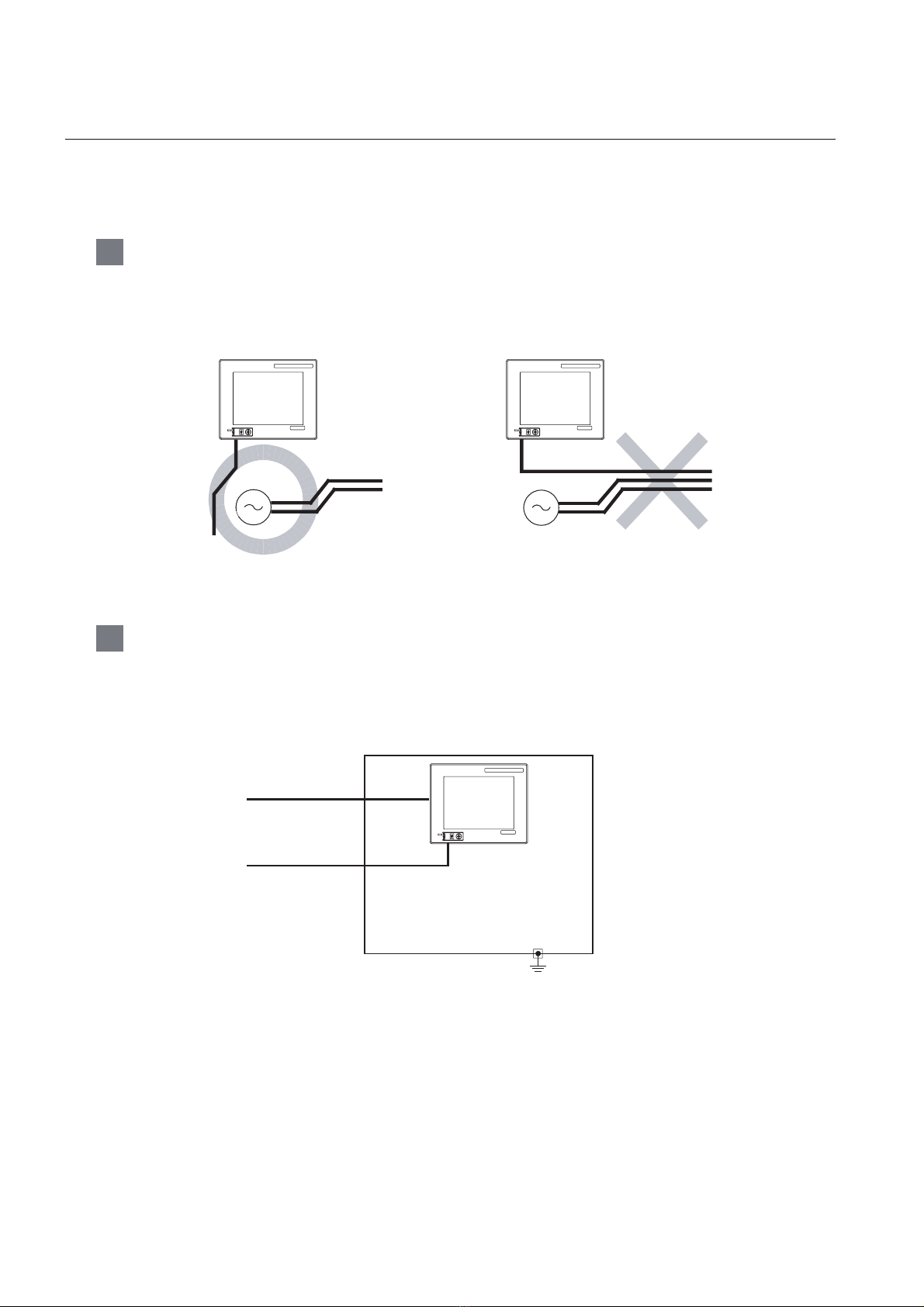
7.1.2 The cause of malfunctions related wiring/Remedy
Grounding of the GOT may cause electric potential difference and noise interference, which may result in
GOT malfunctions.
These problems may be resolved by taking the following measures.
1 Wiring path of the GOT's ground cable and power line
Bundling the GOT's ground cable and power line together can cause interference noise, which may
result in malfunctions.
Keeping the GOT's ground cable and power line away from each other will help minimize noise
interference.
GRAPHIC OPERATION TERMINAL
GOT
1000
GRAPHIC OPERATION TERMINAL
GOT
1000
MITSUBISHI
FG
Power supply for power equipment
Good : Wiring the ground cable away from the
power cable
FG
Power supply for power equipment
Bad : Bundling the ground cable and
the power cable
MITSUBISHI
2 Connecting the ground cable from the panel that houses control equipment to the
panel to which the GOT is grounded
When running a single ground cable from the panel that houses such piece of control equipment as a
sequencer to the panel to which the GOT is grounded, the ground cable may have to be directly
connected to the terminal on the GOT.
GRAPHIC OPERATION TERMINAL
GOT
1000
Connection cable
MITSUBISHI
FG
Ground cable from
the panel that
houses control
equipment
7 - 4
If electric potential difference between the ground points created by it causes malfunctions, lowering the
voltage as shown in Remedy 1 below may solve the problem.
7.1 Power Supply Wiring
7.1.2 The cause of malfunctions related wiring/Remedy
Page 77

• Remedy 1 (Refer to the figures Remedy 1-1 and 1-2 below.)
If the electric potential difference between the ground cable and the panel that houses the GOT is creating
problems, connect the ground cable to the panel also.
If the wiring method as shown in Remedy 1-1 is not feasible, follow Remedy 1-2.
GRAPHIC OPERATION TERMINAL
GOT
Connection cable
Ground cable from
the panel that
houses control
equipment
Use the thickest
cable possible.
1000
MITSUBISHI
FG
Panel grounding
Connection cable
Ground cable from
the panel that
houses control
equipment
Use the thickest
cable possible.
GRAPHIC OPERATION TERMINAL
GOT
1000
MITSUBISHI
FG
Panel grounding
1
2
SYSTEM
3
OVERVIEW
CONFIGURATION
Remedy 1-1
Remedy 1-2
If taking Remedy 1 worsens noise interference, taking Remedy 2 may alleviate it.
• Remedy 2 (Refer to the figures Remedy 2-1 and 2-2 below.)
Attach a ferrite core to the cable if noise from the GOT panel has adverse effects on the GOT when Remedy
1 is taken.
Wind the wire around the ferrite core several times (approx. 3 times), if a ferrite core is used.
If the wiring method as shown in Remedy 2-1 is not feasible, follow Remedy 2-2.
Connection cable
Ground cable from
the panel that
houses control
equipment
Use the thickest
cable possible.
Remedy 2-1
GRAPHIC OPERATION TERMINAL
GOT
1000
Connection cable
Ground cable from
MITSUBISHI
the panel that
houses control
FG
equipment
Use the thickest
Ferrite core Ferrite core
cable possible.
Panel grounding
Remedy 2-2
GRAPHIC OPERATION TERMINAL
GOT
1000
MITSUBISHI
FG
Panel grounding
SPECIFICATIONS
4
PAR T NA M E
5
EMC DIRECTIVE
6
7.1 Power Supply Wiring
7.1.2 The cause of malfunctions related wiring/Remedy
INSTALLATION
7
WIRING
8
OPTION
7 - 5
Page 78

7.2 Wiring inside and outside the panel
7.2.1 Wiring inside
Run power lines, servo amplifier drive wires, and communication cables so that they do not cross each other.
Noise interference that is generated by cables that cross each other may cause malfunctions.
Surge suppressors are an effective way to filter out surge noise that is generated from no fuse breakers
(NFB), electromagnetic contactors (MC), relays (RA), solenoid valves, and induction motors.
Refer to the section to follow for surge killers.
7.2.3 Attaching surge killers to control equipment
Crossing power lines and communication cables
NFB
PLC
GOT connection cable
PLC
I/O wire
Power
cable
NFB
Uncrossed power lines and
communication cables
PLC
GOT connection cable
PLC I/O wire
Power
cable
MC
MC RA RA
Drive control wire
Terminal block
MC
MC RA RA
Drive control wire
Terminal block
7.2.2 Outside the panel
To pull the power line and communication cable out of the panel, make two pullout holes away from each
other and pull the cables through.
Putting both cables through the same pullout hole will increase noise interference.
Power line
Power line
Connection
cable
Pullout hole Pullout hole
Keep the power line and communication cable inside the duct at least 100 mm away from each other.
If that is not possible, the use of a metal separator inside the duct can reduce noise interference.
Connection
cable
7 - 6
100mm or more
Wiring the power line and communication cable inside the duct
7.2 Wiring inside and outside the panel
7.2.1 Wiring inside
Power line
Signal line
Wiring duct Separator
Power line
Signal line
Page 79

7.2.3 Attaching surge killers to control equipment
If communication errors happen in synch with the on/off signals from certain control equipment (referred to
as "load" hereafter) such as no fuse breakers, electromagnetic contactors, relays, solenoid valves, and
induction motors, surge noise interference is suspected.
If this problem happens, keep the ground cable and communication cable away from the load.
If that is not possible, an installation of a surge killer will help reduce noise interference.
Place the surge killer as close to the load as possible.
Remedy for AC inductive load
Keep the ground cable and
communication cable away
from each other.
1
2
SYSTEM
OVERVIEW
CONFIGURATION
Output
Output equipment such as PLC output unit
Remedy for DC inductive load
Keep the ground cable and
communication cable away
from each other.
Output
Output equipment such as PLC output unit
AC
DC
C
R
L:Load
Place the surge killer near the load.
3
SPECIFICATIONS
4
PAR T NA M E
D
L:Load
Place the surge killer near the load.
5
EMC DIRECTIVE
6
7.2 Wiring inside and outside the panel
7.2.3 Attaching surge killers to control equipment
INSTALLATION
7
WIRING
8
OPTION
7 - 7
Page 80

7.2.4 Wiring the FG wire of the BUS cable
1 To connect the QCPU, motion controller CPU (Q series) and GOT
The cable for connection to the QCPU, motion controller CPU (Q series) does not have a FG wire that
needs to be grounded.
2 To connect QnACPU, ACPU, motion controller CPU (A series) and GOT
When using GT15-C EXSS-1 or GT15-C BS, ground the FC wires as shown in the figure below.
(1) GT15-C EXSS-1
Leave unconnected
PLC
GOT
(GT15-C BS)
OUT IN
FG
LG
N
L
(GT15-EXCNB)
2SQ wire to the FG
terminals
to be 28 cm or less
FG
NL
1 Ground the FG terminal of the power supply terminal block on the GOT.
2 FG wires on GT15-C BS must be 28 cm or less.
3 Leave the FG ground wire on GT15-EXCNB unconnected.
4 Connect the FG wire on GT15-C BS on the GOT side to the FG terminal of
the power supply terminal block on the GOT.
5 Connect the FG wire on GT15-C BS on the PLC side to the FG terminal of the
power supply terminal block on the PLC.
6 Connect the LG and FG terminals on the terminal block, and provide a single
grounding point for them.
7 - 8
(2) GT15-C BS
For both GOTs, provide the same grounding as described in the section (1) above to both GOTs.
7.2 Wiring inside and outside the panel
7.2.4 Wiring the FG wire of the BUS cable
Page 81

8. OPTION
1
8.1 CF Card
The CF card is used to transmit the OS or project data and to save the data of the alarm history function.
Refer to the following for details.
Chapter 13 FILE DISPLAY AND COPY (PROGRAM/DATA CONTROL)
8.1.1 Applicable CF card
The following CF cards are applicable for GT11 .
Model Description
GT05-MEM-128MC Flash ROM 128MB
GT05-MEM-256MC Flash ROM 256MB
GT05-MEM-512MC Flash ROM 512MB
GT05-MEM-1GC Flash ROM 1GB
GT05-MEM-2GC Flash ROM 2GB
--
*1 Some models with the operations checked by our company are usable.
For the operation-checked models, refer to "List of valid devices applicable for GOT 1000 series" (T10-0039)
separately available.
The Technical News above is available as a reference at the Information site for Mitsubishi industrial automation
products MELFANSweb home page.
(MELFANSweb home page: http://wwwf2.mitsubishielectric.co.jp/melfansweb/english/index_e.htm)
Commercially-available CF card
*1
2
SYSTEM
3
4
5
OVERVIEW
CONFIGURATION
SPECIFICATIONS
PAR T NA M E
The flash PC card of the GOT-A900 series
In the GT11 , the flash PC card for GOT-A900 series cannot be used.
Use the CF card which is described in the above.
8.1 CF Card
8.1.1 Applicable CF card
EMC DIRECTIVE
6
INSTALLATION
7
WIRING
8
OPTION
8 - 1
Page 82

8.1.2 Installing and removing procedures of the CF card
Install/remove the CF card with the power supply of GOT is OFF or CF card access switch is "OFF".
1 Installing
1 Set the CF card access switch of the GOT to "OFF", and make sure
that the CF card access LED turns off. (When the CF card access LED
turns off, the CF card can be installed even during the GOT power on.)
2 To install the CF card to the GOT, insert the CF card into the CF card
interface with its front side outside.
Push-in the CF card until the CF card eject button snaps.
CF card
access LED
INPUT
24V DC
+-
GT1155-QTBD, GT1155-QSBD,
GT1150-QLBD
CF card access
switch
CF card
I/F
CF card
CF card
front face
3 Turn the CF card access switch on.
After the CF card access switch is turned on, the CF card can be used.
CF card
CF card front face
CF card
eject
button
8 - 2
8.1 CF Card
8.1.2 Installing and removing procedures of the CF card
Page 83

2 Removing
1
1 Set the CF card access switch of the GOT to "OFF."
Make sure that the CF card access LED turns off.
When the CF card access LED turns off, the CF card can be installed
or removed even during the GOT power on.
2 Push-in the CF card eject button of the GOT to eject the CF card,
and then remove the CF card.
CF card
access LED
INPUT
24V DC
+-
GT1155-QTBD, GT1155-QSBD,
GT1150-QLBD
CF card access
switch
CF card
I/F
CF card
2
SYSTEM
3
4
OVERVIEW
CONFIGURATION
SPECIFICATIONS
Push.
CF card
eject
button
Precautions for removing the CF card
(1) While the CF card access LED is on, do not install/remove the CF card or power
off the GOT.
To do so may cause data corruption or malfunction.
(2) When ejecting the CF card, support it by hand since it may pop out.
Failure to do so may cause a fall of the CF card leading to failure or damage of
the card.
PAR T NA M E
5
EMC DIRECTIVE
6
INSTALLATION
7
8.1 CF Card
8.1.2 Installing and removing procedures of the CF card
WIRING
8
OPTION
8 - 3
Page 84

8.2 Memory Card Adaptor
The memory card adaptor is used to convert the CF card into the memory card (Type II).
Install the memory card adaptor to a PC equipped with a PCMCIA interface, to write the OS or project data
on the CF card from the PC or load alarm history data from the CF card to the PC.
Refer to the following for the details related to CF card.
Section 8.1 CF Card
8.2.1 Applicable memory card adaptor
The following memory card adaptor is applicable.
Model Contents
GT05-MEM-ADPC Adaptor converting from CF card to memory card (Type II)
8.2.2 Installing procedure of the CF card into a memory card adaptor
Fit the CF card in the memory card adaptor.
CF card Memory card adaptor
8 - 4
8.2 Memory Card Adaptor
8.2.1 Applicable memory card adaptor
Page 85

8.3 Option Function Board
1 GT1155-QSBD, GT1150-QLBD
To use the optional functions, the option function board is necessary.
For GT11 with hardware version C or later, option function can be used without mounting the option
function board.
Refer to the following for the functions requiring the option function board.
GT Designer2 Version Screen Design Manual
GT Designer3 Version1 Screen Design Manual
Checking method of hardware version
Confirm the hardware version with the products rating plate.
GRAPHIC OPERATION TERMINAL
MODEL
IN 20.4
S/N
MADE IN JAPAN
GT1155-QSBD
26.4VDC
MITSUBISHI ELECTRIC CORPORATION
80M1 IND. CONT. EQ
US LISTED
POWER 9.84W MAX
540001 BC
JY550D26101A
BC
Hardware version
1
2
SYSTEM
3
4
OVERVIEW
CONFIGURATION
SPECIFICATIONS
2 GT1155-QTBD, GT1155-QTBDQ, GT1155-QTBDA, GT1155-QSBDQ,
GT1155-QSBDA,GT1150-QLBDQ, GT1150-QLBDA
The above models of GOTs have built-in option functions and do not require the option function board.
8.3.1 Applicable option function board
The table below shows the type of option function board that can be used with GT1155-QSBD and
GT1150-QLBD.
Model Contents
GT11-50FNB Option function board
8.3.2 Part names
Groove for reverse
installation protection
Lever
for removal
Groove for reverse
installation protection
Connector for connecting GOT
PAR T NA M E
5
EMC DIRECTIVE
6
INSTALLATION
7
WIRING
8
8.3 Option Function Board
8.3.1 Applicable option function board
OPTION
8 - 5
Page 86

8.3.3 How to install or remove the option function board
r
r
1 Installing
1 Turn the GOT power off.
2 Rise the lever on the dummy cover with a fingernail as
shown in the figure on the right.
3 Pinch the lever with fingers and pull-up it vertically to
remove the dummy cover.
4 Install the option function board to the option function board
connector on the back panel of the GOT.
Push-down the option function board by approximately
0.5mm with fingers along the groove for reverse installation
protection.
Cross sectional view (with option function board installed)
*1
*1
Do not keep the option function board in a floated or inclined
status.
Do not touch the circuit board in the GOT main unit during
the option function board installation.
Push-down by
approx. 0.5mm
at four corners.
GOT main unit
*1:Option function
board
*1
InclinedFloated
Dummy cove
Dummy cove
Option function
board
Groove for
reverse installation
protection
2 Removing
1 Turn the GOT power off.
2 Rise the lever for removing the option function board
with a fingernail as shown in the figure on the right.
3 Pinch the lever with fingers and pull-up it vertically to
remove the option function board.
Precautions for installing/removing the option function board
(1) Do not twist the lever when removing the option function board. Otherwise the
lever may be broken.
Option function board
Option function board
Groove for reverse
installation
protection
8 - 6
(2) Install the dummy cover when not using the option function board.
8.3 Option Function Board
8.3.3 How to install or remove the option function board
Page 87

8.4 Battery
r
r
The battery backs up clock data, alarm history and recipe data.
A battery is installed to GT11 when the GT11 is shipped from the factory.
1
8.4.1 Applicable battery
The following battery is applicable for GT11 .
Model Contents
GT11 -50BAT
alarm history, recipe data and time action setting value
8.4.2 Battery specifications
Item Specifications
Type Magnesium manganese dioxide lithium primary battery
Initial voltage 3.0V
Storage life
Application
Remark
For the battery directive in EU member states, refer to 17.4 Handling of Batteries
and Devices with Built-in Batteries in EU Member States.
Approx. 5 years (Operating ambient temperature of 25 )
For backup of clock data, alarm history, recipe data
Battery for backup of clock data,
and time action setting value
2
SYSTEM
3
4
5
OVERVIEW
CONFIGURATION
SPECIFICATIONS
PAR T NA M E
8.4.3 Battery replacement procedure
Replace battery periodically at intervals of 4 to 5 years as reference.
1 Turn the GOT power off.
2 Open the back cover of the GOT.
3 Remove the old battery from the holder.
4 Disconnect the old battery connector and insert the new battery
connector within 30s.
5 Insert the new battery into the holder and close the back cover.
6 Turn the GOT power on.
7 Check if the battery condition is normal with the utility.
Refer to the following for the details of battery status display.
Chapter 12 CLOCK SETTINGS AND BATTERY
STATUS DISPLAY (TIME SETTING AND DISPLAY)
Holder
Connector
Holder
Connector
Back cove
Back cove
EMC DIRECTIVE
6
INSTALLATION
7
WIRING
8
8.4 Battery
8.4.1 Applicable battery
OPTION
8 - 7
Page 88

(1) Battery life
)
The battery life is approximately 5 years.
The production date of the optional replacement battery can be confirmed by the
lot No. marked on the nameplate (label) affixed on the battery.
Nameplate
Connector
Model name
LOT.
<Jan., 2010 or later>
3-digit
1
10
Month
(example: Jan.)
1 (Jan.) to 9 (Sep.),
X (Oct.), Y (Nov.), Z (Dec.)
Year (example: 2010)
Last two digit of year
GT11-50BAT
LOT.101
<Dec., 2009 or before>
2-digit
8
X
Month
(example: Oct.)
1 (Jan.) to 9 (Sep.),
X (Oct.), Y (Nov.), Z (Dec.
Year (example: 2008)
Last digit of year
The production date of the battery built in the purchased GOT can be confirmed
by the production No. (S/N) marked on the GOT main unit.
(a) GT1155-QTBD, GT1155-QSBD, GT1150-QLBD.
Example nameplate (manufacture's serial number 1010001)
GRAPHIC OPERATION TERMINAL
GT1155-QSBD
CF CARD
INPUT
24V DC
+-
I/F
<Jan., 2010 or later>
MODEL
IN 20.4
S/N
MITSUBISHI ELECTRIC CORPORATION
MADE IN JAPAN
POWER 9.84W MAX
26.4VDC
1010001 BC
80M1 IND. CONT. EQ
US LISTED
JY550D26101A
7-digit
01 1 0 0 0
Month (example: Jan.). 1 to 9: Jan. to Sep.,
X: Oct., Y: Nov., Z: Dec.
Year (example: 2010)
Last two digit of year
* Actual product nameplate
differs from the shown above.
1
Control number
8 - 8
8.4 Battery
8.4.3 Battery replacement procedure
<Dec., 2009 or before>
6-digit
9 X 0 0 0
Month (example: Oct.). 1 to 9: Jan. to Sep.,
X: Oct., Y: Nov., Z: Dec.
Year (example: 2009)
Last digit of year
1
Control number
Page 89

(b) GT1155-QTBDQ, GT1155-QTBDA, GT1155-QSBDQ,
GT1155-QSBDA, GT1150-QLBDQ, GT1150-QLBDA
GRAPHIC OPERATION TERMINAL
MODEL
GT1155-QTBDQ
IN 24VDC
POWER MAX 00W
SERIAL
00007201
DP00001-A
MITSUBISHI ELECTRIC
Year (e.g., 2007) The last two digits
of the Western calendar year
0
7
MADE IN JAPAN
2
1
0
Date (e.g., 1st) 1 to 31=1st to 31st
Month
(e.g., February)
1 to 9=Jan. to Sept.,
X = Oct., Y = Nov., Z = Dec.
(2) Battery procurement
The battery is susceptible to natural discharge. Order one when necessary.
1
2
SYSTEM
3
4
OVERVIEW
CONFIGURATION
SPECIFICATIONS
PAR T NA M E
5
EMC DIRECTIVE
6
INSTALLATION
7
WIRING
8.4 Battery
8.4.3 Battery replacement procedure
8
OPTION
8 - 9
Page 90

8.5 Protective Sheet
The protective sheet is used to protect the operation surface from damage or dirt when the touch key of GOT
display section is operated.
8.5.1 Applicable protective sheet
The following protective sheets are applicable for GT11 .
Product name Model Contents
GT11-50PSCB
Protective sheet
GT11-50PSGB Antiglare 5 sheets
Protective sheet for 5.7"
GT11-50PSCW Clear (Frame: White) 5 sheets
GT11-50PSGW Antiglare (Frame: White) 5 sheets
8.5.2 Installing procedure
1 If the protective sheet has been already attached to the GOT,
remove the old one from the GOT display section holding the lower
right corner.
If the protective sheet for transportation is attached to the GOT,
remove it too.
2 Peel the release paper from the back of the new protective sheet,
and attach its adhesive side to the GOT display section.
When attaching the protective sheet, make sure to fit it on the
display section closely without leaving any clearance between them.
Clear 5 sheets
8 - 10
Remark
8.5 Protective Sheet
8.5.1 Applicable protective sheet
Replacement time of protective sheet
Check the status of the protection sheet visually by to the daily inspection.
The visibility becomes worse when there is too much dirt and cracks, causing
malfunction. Proceeds replacement promptly.
Page 91

8.6 USB Environmental Protection Cover
The USB environmental protection cover protects the USB connector on the front face of GOT from dust,
water, and oil.
The GOT is installed with the USB environmental protection cover at factory shipment.
Replace when damage and deterioration are caused.
1
OVERVIEW
8.6.1 Applicable USB environmental protection cover
The following USB environmental protection cover is applicable for GT11 .
Product name Model Contents
USB environmental
protection cover
GT11-50UCOV
Environmental protection cover for USB interface on the main unit front
panel (conforming to IP67)
8.6.2 Installing procedure
1 Turn the GOT power off.
2 Disconnect the USB cable from the GOT if one is connected.
3 Open the USB environmental protection cover equipped with the GOT
and remove the mounting screws.
4 Remove the old USB environmental protection cover from the GOT to
replace it with the new USB environmental protection cover.
5 Fix the new USB environmental protection cover while fitting its
projection to the hole in the GOT, and mount the cover to the GOT, using
the mounting screws.
Open.
Mounting screw
USB environmental
protection cover
Projection
2
SYSTEM
3
4
5
CONFIGURATION
SPECIFICATIONS
PAR T NA M E
Tightening torque 0.36 to 0.48N•m for both mounting screws A and B
Mounting screw A
M3 6 pan head screw
Precautions when the USB environmental protection cover is opened
Environmental protective structure of USB interface is "IP2X" when the USB
environmental protection cover is opened.
Mounting screw B
8.6 USB Environmental Protection Cover
8.6.1 Applicable USB environmental protection cover
EMC DIRECTIVE
6
INSTALLATION
7
WIRING
8
OPTION
8 - 11
Page 92

8.7 Stand
A
Stand is used to fix the GOT to standing status in order to debug the monitor screen data easily.
8.7.1 Applicable stand
The following stand is applicable for GT11 .
Product name Model Contents
Stand
GT05-50STAND
A9GT-50STAND
Stand for 5.7
Stand for 5.7"
"
8.7.2 Installing procedure
1 Adjust the mounting angle of GOT with the angle adjusting fitting of
the stand.
2 Put the GOT into the stand from the stand front side and fix it using
the fixtures.
For how to mount the GOT, refer to the following.
djust to
45 , 55 , 65 or 75 .
Angle adjusting fitting
GOT
mounting face
Section 6.5 Installation Procedure
For details of the stand, refer to the following.
GT05-50STAND
GOT1000 series User's Manual
A9GT-50STAND
A9GT-50STAND User's Manual
8 - 12
8.7 Stand
8.7.1 Applicable stand
Page 93

8.8 Protective cover for oil
Use of the protective cover for oil improves waterproof property, oil resistance, and chemical resistance of
the GOT.
1
8.8.1 Applicable protective cover for oil
The following protective covers for oil are applicable to the GT11 .
Product name Model Contents
Protective cover for oil GT05-50PCO
For 5.7"
GOT
8.8.2 Installation procedure
Before attaching protective cover for oil
A protective film is attached on the display area when the GOT is shipped. Make
sure to remove the protective film before attaching the protective cover for oil.
For attaching the protective cover for oil to the GOT already mounted on the control
panel, follow the procedures as below.
• Remove the GOT from the control panel. Make sure to externally shut off all
phases of the power supply and remove all cables from the GOT in
advance.
• Clean dirt off surfaces of the GOT and control panel.
2
SYSTEM
3
4
OVERVIEW
CONFIGURATION
SPECIFICATIONS
PAR T NA M E
1 When the USB environmental protection cover is installed on the GOT,
remove the cover.
2 After removing the cover, put the USB connector protective sticker on the
USB connector.
3 Position the POWER LED frame of the cover to the POWER LED on the
GOT front face, and the direction of the cover is decided.
GOT
Protective Cover For oil
5
EMC DIRECTIVE
6
INSTALLATION
7
WIRING
8
8.8 Protective cover for oil
8.8.1 Applicable protective cover for oil
OPTION
8 - 13
Page 94

4 One corner of the cover is pulled outside, and it hangs it
on the corner of the front panel of GOT.
Please do not pull the oil cover
more than the necessity,
and do not bend it extremely.
The seat part and the rubber part
in the display part might flake off.
Protective Cover For oil
The corner is hung.
GOT
5 The oil cover was hung and the edge of the oil cover is
sequentially obtained and obtain the oil cover to cover
rubber packing parts in the back of GOT of the front
panel.
(It is the order of the arrow from A side to D side.)
Please confirm all surroundings.
Check whether the rubber packing is fitted correctly into
the groove on the under side of the GOT front panel,
and then whether the protective cover for oil securely
covers the rubber packing part to prevent invasion of
liquids into the board.
6 Mount the GOT onto the control panel.
When the control panel is dirty, clean the control panel.
The panel cutting dimensions and mounting screw tightening
torque with the protective cover for oil are the same as those
without the cover.
The corner on the left is hung and the oil cover is hung
from A side to D side on the starting point sequentially.
A
B
D
C
Make sure that corners of protective
cover for oil match those of GOT front.
Panel cut
Protectivecover
for oil
dimensions
Mounting metal fixture
Control panel
8 - 14
8.8 Protective cover for oil
8.8.2 Installation procedure
Page 95

Precautions for protective cover for oil
• The protective cover for oil is a consumable product.
Check the cover for scratch, damage or dirt at regular intervals, and replace
with new one if necessary.
• Do not push the protective cover for oil with pointed tools, including
mechanical pencils and screwdrivers.
Doing so causes scratches and damages of the cover.
• Do not clean the protective cover for oil with bleaches, thinners, organic
solvents, corrosive chemicals, and others. Doing so causes changes in
shape and color of the cover.
• When the protective cover for oil is attached to the GOT, do not stretch and
bend the cover too much.
Doing so may cause a separation between the sheet and rubber.
• Do not place or use the protective cover for oil in direct sunshine.
• When the protective cover for oil gets dusts, wipe the dusts off with a damp
cloth.
• When the protective cover for oil is used, the USB connector on the GOT
front face cannot be used.
• When the protective cover for oil is used, the human sensor does not
correctly operate.
• Do not do a frequent detaching the protective cover for oil. It causes
deterioration in the waterproof function, the oil performance, and the
medicine performance.
• It is not the one to guarantee all customer's environments. Moreover, it is
not likely to be able to use it in the environment to which oil splashes for a
long time and the environment with which Oilmist is filled.
1
2
SYSTEM
3
4
5
OVERVIEW
CONFIGURATION
SPECIFICATIONS
PAR T NA M E
8.8 Protective cover for oil
8.8.2 Installation procedure
EMC DIRECTIVE
6
INSTALLATION
7
WIRING
8
OPTION
8 - 15
Page 96

8.9 Serial Multi-Drop Connection Unit
8.9.1 Serial multi-drop connection unit
GOT multi-drop connection is a communication method for 1:N communication by connecting multiple GOTs
to one PLC, using the GT01-RS4-M serial multi-drop connection module.
For details of GOT multidrop connection, refer to the following.
GOT1000 Series Connection Manual
• GT Designer2
• GT Designer3
Serial multi drop connection module
Connect to the PLC.
Varies according to
the connection type.
(1) GOTs supporting the GOT multi-drop connection
The followings are the GOTs compatible with the GOT multi-drop connection.
• Communication driver
• Communication interface
RS-485 cable
MAX500m
GOT Hardware version
GT1155-QTBD Hardware version C or later
GT1155-QSBD, GT1150-QLBD Hardware version F or later
• Communication driver
• Communication interface
8 - 16
(2) Checking method of hardware version
Confirm the hardware version with the products rating plate.
GRAPHIC OPERATION TERMINAL
MODEL
IN 20.4
S/N
MITSUBISHI ELECTRIC CORPORATION
MADE IN JAPAN
8.9 Serial Multi-Drop Connection Unit
8.9.1 Serial multi-drop connection unit
GT1155-QSBD
26.4VDC
POWER 9.84W MAX
540001 BC
BC
Hardware version
JY550D26101A
Page 97

8.9.2 Applicable serial multi-drop connection unit
The following serial multi-drop connection unit is applicable.
Model Contents
GT01-RS4-M For GOT multi-drop connection
1
OVERVIEW
8.9.3 Part name
1)
• Protective cover is installed • Protective cover is removed
2)
72
90
80
10)
57
65
2- 4.5
12)
11)
2
5)
4)
3)
7)
6)
9)
8)
SYSTEM
CONFIGURATION
3
SPECIFICATIONS
4
PAR T NA M E
5
No. Name Specifications
1) Installation hole for the main unit Installation hole
POWER Lit in green when the power is properly supplied.
2) LED
3) Terminating resistor selector
4) Connector for PLC communication D-sub 9-pin (male) For RS-232 connection
Connector selection switch for PLC
5)
communication
6) USB port
7) Connector for PLC communication D-sub 9-pin (female) For RS-422 connection
8) Protective cover Protect unused D-sub connector, USB port and switches.
Terminal block for the serial multi-drop
9)
communication
10) Power supply connector
11) Slider for installing the DIN rail -
Mode selection switch
12)
(Slide switch)
SD Lit in green when the data is being sent to PLC.
RD Lit in green when the data is being received from PLC.
ERROR Lit or blinking depending on the status.
Can be selected among 110 , OPEN and 330
(set to "OPEN" by default)
Switch for selecting RS-422 or RS-232 (set to "RS-422" by default)
For connecting to a personal computer (for changing the
communication driver)
Terminal block 5-pin (with a protective cover) M3 Tightening torque
0.5 to 0.6N•m
24VDC power supply connector insertion point (A dedicated cable is
included.)
Do not operate. (Set to right by default. When set to left, the module
does not operate normally.)
8.9 Serial Multi-Drop Connection Unit
8.9.2 Applicable serial multi-drop connection unit
EMC DIRECTIVE
6
INSTALLATION
7
WIRING
8
OPTION
8 - 17
Page 98

8.9.4 Installation
1 Installed with DIN rail
Install the multi-drop connection module with its hook (1 place) using the DIN rail.
• Applicable DIN rail DIN46277 (width: 35mm)
(Install the DIN rail with screws at intervals of 150mm.)
2 Directly installed to panel
Install the multi-drop connection module to the panel using 4.5mm holes (2 places).
8.9.5 Caution for compliance with EMC Directive
Programmable logic controllers are open-type devices that must be installed and used within conductive
control boxes. Please use the Multi-Drop Connection Unit while installed in conductive shielded control
boxes. Please secure the control box lid to the control box (for conduction). Installation within a control box
greatly affects the safety of the system and aids in shielding noise from the Multi-Drop Connection Unit.
8 - 18
8.9 Serial Multi-Drop Connection Unit
8.9.4 Installation
Page 99

8.10 Connector Conversion Adapter
GT10-9PT5S type connector conversion adapter enables an easy crossover wiring for the multi-dropconncted GOTs.
For the wiring between the connector conversion adapter and the controller, refer to the following manual.
GOT1000 Series Connection Manual
(1) GOTs supporting the connector conversion adapter
The followings are the GOTs compatible with the connector conversion adapter.
GOT Hardware version
GT1155-QTBD Hardware version C or later
GT1155-QSBD, GT1150-QLBD Hardware version F or later
(2) Checking method of hardware version
Confirm the hardware version with the products rating plate.
GRAPHIC OPERATION TERMINAL
MODEL
IN 20.4
S/N
MADE IN JAPAN
GT1155-QSBD
26.4VDC
MITSUBISHI ELECTRIC CORPORATION
POWER 9.84W MAX
540001 BC
JY550D26101A
BC
Hardware version
1
2
SYSTEM
3
4
5
OVERVIEW
CONFIGURATION
SPECIFICATIONS
PAR T NA M E
8.10.1 Applicable connector conversion adapter
The following connector conversion adapter is applicable.
Model Contents
GT10-9PT5S For GOT multi-drop connection
8.10.2 Installing procedure
1 Turn the GOT power off.
2 Connect the connection conversion adapter to the RS-422/485
interface on the GOT.
3 Fix the connection conversion adapter to the GOT using the
provided M3 tapping screws.
4 Tightening torque: 0.3 to 0.6 N
•m
EMC DIRECTIVE
6
INSTALLATION
7
WIRING
8
8.10 Connector Conversion Adapter
8.10.1 Applicable connector conversion adapter
OPTION
8 - 19
Page 100

9. UTILITY FUNCTION
Utility is a function, which carries out connection of GOT and PLC, screen display and operation method
settings, program/data control and self-check etc.
Refer to the following for the utility function list.
Section 9.2 Utility Function List
9.1 Utility Execution
For utility execution, utility has to be displayed by installing BootOS and Standard monitor OS in the C drive
(Flash memory).
There are following three types for the installing Standard monitor OS methods.
1) Drawing software GOT
Via USB interface or
RS-232 interface
GOT
• Installed directly from the drawing software
GT Designer2
GT Designer3
2) Drawing software CF card GOT
BootOS or Standard monitor OS installation
OS file
write
BootOS or Standard
monitor OS installation
GOT
Install the CF
GT Designer2
GT Designer3
3) GOT CF card GOT
OS file
upload
CF card
GOT
CF card
Refer to the following for the installation which uses drawing software.
GT Designer2 Version Basic Operation/Data Transfer Manual
GT Designer3 Version1 Screen Design Manual (Fundamentals)
Refer to the following for the installation which uses GOT.
Chapter 16 INSTALLATION OF CoreOS, BOOTOS AND STANDARD MONITOR OS
card in GOT
BootOS, Standard
monitor OS installation
GOT
Install the CF
card in GOT
• When GOT is remote, installed easily
using the CF card
• Install OS from GOT to GOT using CF card
9 - 1
9.1 Utility Execution
 Loading...