

Page 1
BUS CONNECTION
DIRECT CONNECTION TO CPU
COMPUTER LINK CONNECTION
ETHERNET CONNECTION
MELSECNET/H CONNECTION
MELSECNET/10 CONNECTION
CC-Link IE CONNECTION
CC-Link CONNECTION
INVERTER CONNECTION
SERVO AMPLIFIER CONNECTION
ROBOT CONTROLLER CONNECTION
CNC CONNECTION
GOT MULTI-DROP CONNECTION
MULTIPLE-GT14, GT12, GT11, GT10 CONNECTION FUNCTION
MULTI-CHANNEL FUNCTION
FA TRANSPARENT FUNCTION
Series
Connection Manual
(Mitsubishi Products)
BUS CONNECTION
BUS CONNECTION
DIRECT CONNECTION TO CPU
DIRECT CONNECTION TO CPU
COMPUTER LINK CONNECTION
COMPUTER LINK CONNECTION
ETHERNET CONNECTION
ETHERNET CONNECTION
MELSECNET/H CONNECTION
MELSECNET/H CONNECTION
MELSECNET/10 CONNECTION
MELSECNET/10 CONNECTION
CC-Link IE CONNECTION
CC-Link IE CONNECTION
CC-Link CONNECTION
CC-Link CONNECTION
INVERTER CONNECTION
INVERTER CONNECTION
SERVO AMPLIFIER CONNECTION
SERVO AMPLIFIER CONNECTION
ROBOT CONTROLLER CONNECTION
ROBOT CONTROLLER CONNECTION
for GT Works3 (ELE)
CNC CONNECTION
CNC CONNECTION
GOT MULTI-DROP CONNECTION
GOT MULTI-DROP CONNECTION
MULTIPLE-GT14, GT12, GT11, GT10 CONNECTION FUNCTION
MULTIPLE-GT14, GT12, GT11, GT10 CONNECTION FUNCTION
MULTI-CHANNEL FUNCTION
MULTI-CHANNEL FUNCTION
FA TRANSPARENT FUNCTION
FA TRANSPARENT FUNCTION
Page 2

Page 3
SAFETY PRECAUTIONS
WARNING
Indicates that incorrect handling may cause hazardous conditions,
resulting in death or severe injury.
CAUTION
Indicates that incorrect handling may cause hazardous conditions,
resulting in medium or slight personal injury or physical damage.
(Always read these precautions before using this equipment.)
Before using this product, please read this manual and the relevant manuals introduced in this manual
carefully and pay full attention to safety to handle the product correctly.
The precautions given in this manual are concerned with this product.
In this manual, the safety precautions are ranked as "WARNING" and "CAUTION".
Note that the caution level may lead to a serious accident according to the circumstances.
Always follow the instructions of both levels because they are important to personal safety.
Please save this manual to make it accessible when required and always forward it to the end user.
[DESIGN PRECAUTIONS]
WARNING
● Some failures of the GOT, communication unit or cable may keep the outputs on or off.
An external monitoring circuit should be provided to check for output signals which may lead to a
serious accident.
Not doing so can cause an accident due to false output or malfunction.
● If a communication fault (including cable disconnection) occurs during monitoring on the GOT,
communication between the GOT and PLC CPU is suspended and the GOT becomes inoperative.
For bus connection : The CPU becomes faulty and the GOT becomes inoperative.
For other than bus connection : The GOT becomes inoperative.
A system where the GOT is used should be configured to perform any significant operation to the
system by using the switches of a device other than the GOT on the assumption that a GOT
communication fault will occur.
Not doing so can cause an accident due to false output or malfunction.
● Do not use the GOT as the warning device that may cause a serious accident.
An independent and redundant hardware or mechanical interlock is required to configure the device
that displays and outputs serious warning.
Failure to observe this instruction may result in an accident due to incorrect output or malfunction.
A - 1
Page 4
[DESIGN PRECAUTIONS]
WARNING
● Incorrect operation of the touch switch(s) may lead to a serious accident if the GOT backlight is gone
out.
When the GOT backlight goes out, the display section dims, while the input of the touch switch(s)
remains active.
This may confuse an operator in thinking that the GOT is in "screensaver" mode, who then tries to
release the GOT from this mode by touching the display section, which may cause a touch switch to
operate.
Note that the following occurs on the GOT when the backlight goes out.
<When using the GT1655-V, Handy GOT, GT15, GT14, GT12, GT11, or GT105 >
The POWER LED blinks (green/orange) and the monitor screen appears blank.
<When using the GT1695, GT1685, GT1675, GT1672, GT1665, or GT1662>
The POWER LED blinks (green/orange) and the monitor screen appears dimmed.
<When using the GT104 >
The monitor screen appears blank.
<When using the GT103 or GT102 >
The monitor screen appears dimmed.
● The display section of the GT16, GT1595-X, GT14, GT12 or GT1020 are an analog-resistive type
touch panel.
If you touch the display section simultaneously in 2 points or more, the switch that is located around
the center of the touched point, if any, may operate.
Do not touch the display section in 2 points or more simultaneously.
Doing so may cause an accident due to incorrect output or malfunction.
● When programs or parameters of the controller (such as a PLC) that is monitored by the GOT are
changed, be sure to reset the GOT or shut off the power of the GOT at the same time.
Not doing so can cause an accident due to false output or malfunction.
CAUTION
● Do not bundle the control and communication cables with main-circuit, power or other wiring.
Run the above cables separately from such wiring and keep them a minimum of 100mm apart.
Not doing so noise can cause a malfunction.
● Do not press the GOT display section with a pointed material as a pen or driver.
Doing so can result in a damage or failure of the display section.
● When the GOT is connected to the Ethernet network, the available IP address is restricted according
to the system configuration.
• When multiple GOTs are connected to the Ethernet network:
Do not set the IP address (192.168.0.18) for the GOTs and the controllers in the network.
• When a single GOT is connected to the Ethernet network:
Do not set the IP address (192.168.0.18) for the controllers except the GOT in the network.
Doing so can cause the IP address duplication. The duplication can negatively affect the
communication of the device with the IP address (192.168.0.18).
The operation at the IP address duplication depends on the devices and the system.
● Turn on the controllers and the network devices to be ready for communication before they
communicate with the GOT.
Failure to do so can cause a communication error on the GOT.
A - 2
Page 5
[MOUNTING PRECAUTIONS]
WARNING
● Be sure to shut off all phases of the external power supply used by the system before mounting or
removing the GOT to/from the panel.
Not switching the power off in all phases can cause a unit failure or malfunction.
● Be sure to shut off all phases of the external power supply used by the system before mounting or
removing the communication unit, option function board or multi-color display board onto/from the
GOT.
Not doing so can cause the unit to fail or malfunction.
● Before mounting an optional function board or Multi-color display board, wear a static discharge wrist
strap to prevent the board from being damaged by static electricity.
CAUTION
● Use the GOT in the environment that satisfies the general specifications described in the User's
Manual.
Not doing so can cause an electric shock, fire, malfunction or product damage or deterioration.
● When mounting the GOT to the control panel, tighten the mounting screws in the specified torque
range.
Undertightening can cause the GOT to drop, short circuit or malfunction.
Overtightening can cause a drop, short circuit or malfunction due to the damage of the screws or the
GOT.
● When loading the communication unit or option unit to the GOT (GT16, GT15), fit it to the extension
interface of the GOT and tighten the mounting screws in the specified torque range.
Undertightening can cause the GOT to drop, short circuit or malfunction.
Overtightening can cause a drop, failure or malfunction due to the damage of the screws or unit.
● When mounting the multi-color display board onto the GOT (GT15), connect it to the corresponding
connector securely and tighten the mounting screws within the specified torque range.
Loose tightening may cause the unit and/or GOT to malfunction due to poor contact.
Overtightening may damage the screws, unit and/or GOT; they might malfunction.
● When mounting the option function board onto the GOT (GT16), connect it to the corresponding
connector securely and tighten the mounting screws within the specified torque range.
● When mounting an optional function board onto the GOT(GT15), fully connect it to the connector
until you hear a click.
● When mounting an optional function board onto the GOT(GT11), fully connect it to the connector.
● When inserting a CF card into the GOT(GT16, GT15, GT11), push it into the CF card interface of
GOT until the CF card eject button will pop out.
Failure to do so may cause a malfunction due to poor contact.
● When inserting/removing a SD card into/from the GOT(GT14), turn the SD card access switch off in
advance.
Failure to do so may corrupt data within the SD card.
A - 3
Page 6
[MOUNTING PRECAUTIONS]
CAUTION
● When inserting/removing a CF card into/from the GOT(GT16, GT15, GT11), turn the CF card access
switch off in advance.
Failure to do so may corrupt data within the CF card.
● When removing a SD card from the GOT(GT14), make sure to support the SD card by hand, as it
may pop out.
Failure to do so may cause the SD card to drop from the GOT and break.
● When removing a CF card from the GOT, make sure to support the CF card by hand, as it may pop
out.
Failure to do so may cause the CF card to drop from the GOT and break.
● When installing a USB memory to the GOT(GT16, GT14), make sure to install the USB memory to
the USB interface firmly.
Failure to do so may cause a malfunction due to poor contact.
●
Before removing the USB memory from the GOT(GT16, GT14), operate the utility screen for removal.
After the successful completion dialog box is displayed, remove the memory by hand carefully.
Failure to do so may cause the USB memory to drop, resulting in a damage or failure of the memory.
● For closing the USB environmental protection cover, fix the cover by pushing the mark on the latch
firmly to comply with the protective structure.
● Remove the protective film of the GOT.
When the user continues using the GOT with the protective film, the film may not be removed.
● Operate and store the GOT in environments without direct sunlight, high temperature, dust, humidity,
and vibrations.
● When using the GOT in the environment of oil or chemicals, use the protective cover for oil.
Failure to do so may cause failure or malfunction due to the oil or chemical entering into the GOT.
[WIRING PRECAUTIONS]
WARNING
● Be sure to shut off all phases of the external power supply used by the system before wiring.
Failure to do so may result in an electric shock, product damage or malfunctions.
CAUTION
● Please make sure to ground FG terminal and LG terminal and protective ground terminal of the GOT
power supply section by applying Class D Grounding (Class 3 Grounding Method) or higher which is
used exclusively for the GOT.
Not doing so may cause an electric shock or malfunction.
● Be sure to tighten any unused terminal screws with a torque of 0.5 to 0.8N•m.
Failure to do so may cause a short circuit due to contact with a solderless terminal.
● Use applicable solderless terminals and tighten them with the specified torque.
If any solderless spade terminal is used, it may be disconnected when the terminal screw comes
loose, resulting in failure.
A - 4
Page 7
[WIRING PRECAUTIONS]
CAUTION
● Correctly wire the GOT power supply section after confirming the rated voltage and terminal
arrangement of the product.
Not doing so can cause a fire or failure.
● Tighten the terminal screws of the GOT power supply section in the specified torque range.
Undertightening can cause a short circuit or malfunction.
Overtightening can cause a short circuit or malfunction due to the damage of the screws or the GOT.
● Exercise care to avoid foreign matter such as chips and wire offcuts entering the GOT.
Not doing so can cause a fire, failure or malfunction.
● The module has an ingress prevention label on its top to prevent foreign matter, such as wire offcuts,
from entering the module during wiring.
Do not peel this label during wiring.
Before starting system operation, be sure to peel this label because of heat dissipation.
● Plug the bus connection cable by inserting it into the connector of the connected unit until it "clicks".
After plugging, check that it has been inserted snugly.
Not doing so can cause a malfunction due to a contact fault.
● Plug the communication cable into the connector of the connected unit and tighten the mounting and
terminal screws in the specified torque range.
Undertightening can cause a short circuit or malfunction.
Overtightening can cause a short circuit or malfunction due to the damage of the screws or unit.
● Plug the QnA/ACPU/Motion controller (A series) bus connection cable by inserting it into the
connector of the connected unit until it "clicks".
After plugging, check that it has been inserted snugly.
Not doing so can cause a malfunction due to a contact fault.
[TEST OPERATION PRECAUTIONS]
WARNING
● Before performing the test operations of the user creation monitor screen (such as turning ON or
OFF bit device, changing the word device current value, changing the settings or current values of
the timer or counter, and changing the buffer memory current value), read through the manual
carefully and make yourself familiar with the operation method.
During test operation, never change the data of the devices which are used to perform significant
operation for the system.
False output or malfunction can cause an accident.
A - 5
Page 8
[STARTUP/MAINTENANCE PRECAUTIONS]
WARNING
● When power is on, do not touch the terminals.
Doing so can cause an electric shock or malfunction.
● Correctly connect the battery connector.
Do not charge, disassemble, heat, short-circuit, solder, or throw the battery into the fire.
Doing so will cause the battery to produce heat, explode, or ignite, resulting in injury and fire.
● Before starting cleaning or terminal screw retightening, always switch off the power externally in all
phases.
Not switching the power off in all phases can cause a unit failure or malfunction.
Undertightening can cause a short circuit or malfunction.
Overtightening can cause a short circuit or malfunction due to the damage of the screws or unit.
CAUTION
● Do not disassemble or modify the unit.
Doing so can cause a failure, malfunction, injury or fire.
● Do not touch the conductive and electronic parts of the unit directly.
Doing so can cause a unit malfunction or failure.
● The cables connected to the unit must be run in ducts or clamped.
Not doing so can cause the unit or cable to be damaged due to the dangling, motion or accidental
pulling of the cables or can cause a malfunction due to a cable connection fault.
● When unplugging the cable connected to the unit, do not hold and pull the cable portion.
Doing so can cause the unit or cable to be damaged or can cause a malfunction due to a cable
connection fault.
● Do not drop or apply strong impact to the unit.
Doing so may damage the unit.
● Do not drop or give an impact to the battery mounted to the unit.
Doing so may damage the battery, causing the battery fluid to leak inside the battery.
If the battery is dropped or given an impact, dispose of it without using.
● Before touching the unit, always touch grounded metal, etc. to discharge static electricity from
human body, etc.
Not doing so can cause the unit to fail or malfunction.
● Replace battery with GT15-BAT(GT16, GT15) or GT11-50BAT(GT14, GT12, GT11, GT10) by
Mitsubishi electric Co. only.
Use of another battery may present a risk of fire or explosion.
● Dispose of used battery promptly.
Keep away from children. Do not disassemble and do not dispose of in fire.
A - 6
Page 9
[TOUCH PANEL PRECAUTIONS]
CAUTION
● For the analog-resistive film type touch panels, normally the adjustment is not required. However,
the difference between a touched position and the object position may occur as the period of use
elapses. When any difference between a touched position and the object position occurs, execute
the touch panel calibration.
● When any difference between a touched position and the object position occurs, other object may be
activated. This may cause an unexpected operation due to incorrect output or malfunction.
[BACKLIGHT REPLACEMENT PRECAUTIONS]
WARNING
● Be sure to shut off all phases of the external power supply of the GOT (and the PLC CPU in the case
of a bus topology) and remove the GOT from the control panel before replacing the backlight (when
using the GOT with the backlight replaceable by the user).
Not doing so can cause an electric shock.
Replacing a backlight without removing the GOT from the control panel can cause the backlight or
control panel to drop, resulting in an injury.
CAUTION
● Wear gloves for the backlight replacement when using the GOT with the backlight replaceable by the
user.
Not doing so can cause an injury.
● Before replacing a backlight, allow 5 minutes or more after turning off the GOT when using the GOT
with the backlight replaceable by the user.
Not doing so can cause a burn from heat of the backlight.
[DISPOSAL PRECAUTIONS]
CAUTION
● When disposing of the product, handle it as industrial waste.
● When disposing of this product, treat it as industrial waste. When disposing of batteries, separate
them from other wastes according to the local regulations.
(For details of the battery directive in EU member states, refer to the User's Manual of the GOT to be
used.)
A - 7
Page 10

[TRANSPORTATION PRECAUTIONS]
CAUTION
● When transporting lithium batteries, make sure to treat them based on the transport regulations.
(For details on models subject to restrictions, refer to the User's Manual for the GOT you are using.)
● Make sure to transport the GOT main unit and/or relevant unit(s) in the manner they will not be
exposed to the impact exceeding the impact resistance described in the general specifications of the
User's Manual, as they are precision devices.
Failure to do so may cause the unit to fail.
Check if the unit operates correctly after transportation.
A - 8
Page 11

INTRODUCTION
Thank you for choosing Mitsubishi Graphic Operation Terminal (Mitsubishi GOT).
Read this manual and make sure you understand the functions and performance of the GOT thoroughly
in advance to ensure correct use.
CONTENTS
SAFETY PRECAUTIONS .........................................................................................................................A - 1
INTRODUCTION ...................................................................................................................................... A - 9
CONTENTS .............................................................................................................................................. A - 9
MANUALS...............................................................................................................................................A - 20
QUICK REFERENCE .............................................................................................................................A - 22
ABBREVIATIONS AND GENERIC TERMS ...........................................................................................A - 24
HOW TO READ THIS MANUAL .............................................................................................................A - 29
1.PREPARATORY PROCEDURES FOR MONITORING
1.1 Setting the Communication Interface............................................................................................... 1 - 3
1.1.1 Setting connected equipment (Channel setting)................................................................... 1 - 4
1.1.2 I/F communication setting................................................................................................... 1 - 12
1.1.3 Precautions......................................................................................................................... 1 - 14
1.2 Writing the Project Data and OS onto the GOT............................................................................. 1 - 15
1.2.1 Writing the project data and OS onto the GOT................................................................... 1 - 15
1.2.2 Checking the project data and OS writing on GOT ............................................................ 1 - 16
1.3 Option Devices for the Respective Connection ............................................................................. 1 - 17
1.3.1 Communication module...................................................................................................... 1 - 17
1.3.2 Option unit .......................................................................................................................... 1 - 18
1.3.3 Conversion cables .............................................................................................................. 1 - 18
1.3.4 Connector conversion adapter ........................................................................................... 1 - 18
1.3.5 Serial Multi-Drop Connection Unit ...................................................................................... 1 - 18
1.3.6 RS-232/485 signal conversion adapter .............................................................................. 1 - 18
1.3.7 Installing a unit on another unit (Checking the unit installation position) ............................ 1 - 19
1.4 Connection Cables for the Respective Connection ....................................................................... 1 - 26
1.4.1 GOT connector specifications ............................................................................................ 1 - 26
1.4.2 Coaxial cable connector connection method...................................................................... 1 - 29
1.4.3 Terminating resistors of GOT ............................................................................................. 1 - 30
1.4.4 Setting the RS-232/485 signal conversion adaptor ............................................................ 1 - 33
1.5 Verifying GOT Recognizes Connected Equipment........................................................................ 1 - 34
1.6 Checking for Normal Monitoring .................................................................................................... 1 - 39
1.6.1 Check on the GOT.............................................................................................................. 1 - 39
1.6.2 Confirming the communication state on the GOT side (For Ethernet connection) ............. 1 - 45
1.6.3 Confirming the communication state to each station (Station monitoring function) ............ 1 - 47
1.6.4 Check on GX Developer.................................................................................................... 1 - 50
1.6.5 Check on GX Works2 .........................................................................................................1 - 54
1.6.6 Check on the PLC ............................................................................................................. 1 - 55
A - 9
Page 12

MITSUBISHI PLC CONNECTIONS
2.DEVICE RANGE THAT CAN BE SET
2.1 MELSEC-QnU/DC, Q17nD/M/NC/DR, CRnD-700........................................................................... 2 - 8
2.2 MELSEC-L ....................................................................................................................................... 2 - 9
2.3 MELSEC-QnA/Q/QS, MELDAS C6 * ............................................................................................. 2 - 10
2.4 MELSEC-Q (Multi)/Q Motion ......................................................................................................... 2 - 11
2.5 MELSEC-A .................................................................................................................................... 2 - 12
2.6 MELSEC-FX .................................................................................................................................. 2 - 13
2.7 MELSEC-WS ................................................................................................................................. 2 - 14
3.ACCESS RANGE FOR MONITORING
3.1 Access Range for Monitoring Stations on Network Systems........................................................... 3 - 2
3.1.1 MELSECNET/H, MELSECNET/10, CC-Link IE Controller Network,
CC-Link IE Field Network ..................................................................................................... 3 - 2
3.2 Access Range for Monitoring when Using Ethernet Connection ................................................... 3 - 13
3.3 CC-Link System Access Range for Monitoring.............................................................................. 3 - 14
3.4 Data Link System (MELSECNET/B, (II)) Access Range for Monitoring ........................................ 3 - 17
3.5 Access Range for Monitoring when Connecting FXCPU............................................................... 3 - 18
3.6 Connection to Remote I/O Station in MELSECNET/H Network System........................................ 3 - 19
3.7 Connection to the Head Module of CC-Link IE Field Network System .......................................... 3 - 22
4.HOW TO MONITOR REDUNTANT SYSTEM
4.1 Connection to Remote I/O Station in MELSECNET/H Network System.......................................... 4 - 8
4.1.1 Direct CPU connection (Direct CPU connection to the remote I/O station) .......................... 4 - 8
4.1.2 Computer link connection
(Connection to serial communication module mounted on remote I/O station) .................... 4 - 9
4.1.3 Ethernet connection (Connection to Ethernet module mounted on remote I/O station) ..... 4 - 10
4.2 Direct CPU Connection.................................................................................................................. 4 - 11
4.2.1 When using one GOT .........................................................................................................4 - 11
4.2.2 When using two GOTs........................................................................................................4 - 12
4.2.3 Precautions when connecting a GOT directly to a PLC CPU in the redundant system
without making Q redundant setting ................................................................................... 4 - 13
4.3 CC-Link Connection (Intelligent Device Station)............................................................................ 4 - 18
4.4 CC-Link Connection (Via G4) ........................................................................................................ 4 - 20
4.5 MELSECNET/H and MELSECNET/10 Connections (Network Systems) ...................................... 4 - 22
4.6 CC-Link IE Controller Network Connection (Network System) ...................................................... 4 - 23
4.7 Ethernet Connection ...................................................................................................................... 4 - 24
4.8 Connection to the Redundant Type Extension Base Unit.............................................................. 4 - 25
4.8.1 Computer link connection (Connection to the Serial communication module mounted
on the redundant type extension base unit)........................................................................ 4 - 25
4.8.2 Ethernet connection (Connection to the Ethernet module mounted on redundant type
extension base unit)............................................................................................................4 - 26
4.8.3 CC-Link connection (intelligent device station) (Connection to the CC-Link module
mounted on redundant type extension base unit)............................................................... 4 - 27
A - 10
Page 13

4.8.4 CC-Link connection (Via G4)
(Connection to the CC-Link module mounted on redundant type extension base unit) ..... 4 - 28
4.9 Q Redundant Setting ..................................................................................................................... 4 - 29
4.10 Switch the Monitor Target to the Control System Using the Script Function ................................. 4 - 31
4.10.1 Method for using the station number switching function..................................................... 4 - 31
4.10.2 Method for using the screen changing function .................................................................. 4 - 38
5.BUS CONNECTION
5.1 Connectable Model List ................................................................................................................... 5 - 2
5.2 System Configuration ...................................................................................................................... 5 - 5
5.2.1 Connecting to QCPU ............................................................................................................ 5 - 5
5.2.2 Connecting to QnACPU or AnCPU ...................................................................................... 5 - 9
5.2.3 Connection to QnASCPU or AnSCPU................................................................................ 5 - 12
5.2.4 Connection to A0J2HCPU .................................................................................................. 5 - 18
5.2.5 Connection to motion controller CPU
(A273UCPU, A273UHCPU(-S3), A373UCPU(-S3)) ........................................................... 5 - 19
5.2.6 Connecting to motion controller CPU
(A171SCPU(-S3(N)), A171SHCPU(N), A172SHCPU(N), A173UHCPU(-S1))................... 5 - 24
5.3 GOT Side Settings......................................................................................................................... 5 - 30
5.3.1 Setting communication interface (Communication settings)............................................... 5 - 30
5.3.2 Communication detail settings............................................................................................ 5 - 30
5.4 Precautions.................................................................................................................................... 5 - 34
5.4.1 GT15-C [ ] EXSS-1, GT15-C [ ] BS .................................................................................. 5 - 34
5.4.2 Turning the GOT ON .......................................................................................................... 5 - 34
5.4.3 Powering OFF the GOT, reapplying the power (OFF to ON) ............................................. 5 - 35
5.4.4 Reset switch on GOT ......................................................................................................... 5 - 35
5.4.5 Powering OFF or resetting the PLC ................................................................................... 5 - 35
5.4.6 Position of the GOT ............................................................................................................ 5 - 35
5.4.7 When the GOT is bus-connected to a PLC CPU without the communication driver
written ................................................................................................................................. 5 - 35
5.4.8 When designing the system ............................................................................................... 5 - 36
5.4.9 When assigning GOT I/O signals ....................................................................................... 5 - 36
5.4.10 When connecting to a QCPU (Q mode) ............................................................................. 5 - 36
5.4.11 When connecting to a QnA(S)CPU or An(S)CPU type ...................................................... 5 - 37
5.4.12 When connecting multiple GOTs ........................................................................................ 5 - 38
5.4.13 When using a PLC CPU in the direct mode ....................................................................... 5 - 38
5.4.14 When connecting to a Q4ARCPU redundant system ......................................................... 5 - 39
5.4.15 When monitoring the Q170MCPU ...................................................................................... 5 - 39
5.4.16 Troubleshooting .................................................................................................................. 5 - 39
6.DIRECT CONNECTION TO CPU
6.1 Connectable Model List ................................................................................................................... 6 - 2
6.2 System Configuration ...................................................................................................................... 6 - 6
6.2.1 Connecting to QCPU ............................................................................................................ 6 - 6
6.2.2 Connecting to LCPU............................................................................................................. 6 - 7
6.2.3 Connecting to QnACPU........................................................................................................ 6 - 8
6.2.4 Connecting to ACPU ............................................................................................................ 6 - 9
6.2.5 Connecting to FXCPU ........................................................................................................6 - 10
6.2.6 Connecting to WSCPU ....................................................................................................... 6 - 20
6.2.7 Connecting to the motion controller CPU ........................................................................... 6 - 20
A - 11
Page 14

6.3 Connection Diagram ...................................................................................................................... 6 - 22
6.3.1 RS-232 cable ...................................................................................................................... 6 - 22
6.3.2 RS-422 cable ...................................................................................................................... 6 - 23
6.4 GOT Side Settings ......................................................................................................................... 6 - 25
6.4.1 Setting communication interface (Communication settings) ............................................... 6 - 25
6.4.2 Communication detail settings ............................................................................................ 6 - 25
6.5 Precautions .................................................................................................................................... 6 - 28
7.COMPUTER LINK CONNECTION
7.1 Connectable Model List ................................................................................................................... 7 - 2
7.1.1 PLC/Motion controller CPU................................................................................................... 7 - 2
7.1.2 Serial communication module/Computer link module........................................................... 7 - 6
7.2 System Configuration ...................................................................................................................... 7 - 7
7.2.1 Connecting to QCPU (Q mode) ............................................................................................ 7 - 7
7.2.2 Connecting to LCPU ............................................................................................................. 7 - 8
7.2.3 Connecting to QCPU (A mode) ............................................................................................ 7 - 9
7.2.4 Connecting to QnACPU (QnACPU type) ............................................................................ 7 - 10
7.2.5 Connecting to QnACPU (QnASCPU type) ......................................................................... 7 - 11
7.2.6 Connecting to ACPU (AnCPU type) ................................................................................... 7 - 13
7.2.7 Connecting to ACPU (AnSCPU type, A0J2HCPU, A2CCPUC) ......................................... 7 - 14
7.3 Connection Diagram ...................................................................................................................... 7 - 15
7.3.1 RS-232 cable ...................................................................................................................... 7 - 15
7.3.2 RS-422 cable ...................................................................................................................... 7 - 17
7.4 GOT Side Settings ......................................................................................................................... 7 - 19
7.4.1 Setting communication interface (Communication settings) ............................................... 7 - 19
7.4.2 Communication detail settings ............................................................................................ 7 - 19
7.5 PLC Side Setting ........................................................................................................................... 7 - 22
7.5.1 Connecting serial communication module (Q, L Series)..................................................... 7 - 22
7.5.2 Connecting serial communication module (QnA Series) .................................................... 7 - 24
7.5.3 Connecting computer link module ...................................................................................... 7 - 25
7.6 Precautions .................................................................................................................................... 7 - 29
8.ETHERNET CONNECTION
8.1 Connectable Model List ................................................................................................................... 8 - 2
8.1.1 PLC/Motion controller CPU................................................................................................... 8 - 2
8.1.2 Ethernet module ................................................................................................................... 8 - 6
8.2 System Configuration ...................................................................................................................... 8 - 7
8.2.1 Connection to Ethernet module ............................................................................................ 8 - 7
8.2.2 Connection to Built-in Ethernet port CPU or C Controller module ...................................... 8 - 11
8.2.3 Connecting to Display I/F.................................................................................................... 8 - 12
8.2.4 Connection to CC-Link IE Field Network Ethernet Adapter Module ................................... 8 - 13
8.2.5 Connecting to PERIPHERAL I/F (Built-in Ethernet port Motion Controller CPU) ............... 8 - 14
8.3 GOT Side Settings ......................................................................................................................... 8 - 15
8.3.1 Setting communication interface (Communication settings) ............................................... 8 - 15
8.3.2 Communication detail settings ............................................................................................ 8 - 15
8.3.3 Ethernet setting................................................................................................................... 8 - 17
8.3.4 Routing parameter setting ..................................................................................................8 - 18
8.4 PLC Side Setting ........................................................................................................................... 8 - 20
8.4.1 Connecting to Built-in Ethernet port CPU (one-to-one connection) .................................... 8 - 20
A - 12
Page 15

8.4.2 Connecting to Built-in Ethernet port CPU (multiple connection)......................................... 8 - 22
8.4.3 Connecting to Ethernet module (Q/L Series)...................................................................... 8 - 24
8.4.4 Connecting to C Controller module .................................................................................... 8 - 27
8.4.5 Connecting to Ethernet module (QnA Series) .................................................................... 8 - 30
8.4.6 Connecting to Ethernet module (A Series) ......................................................................... 8 - 33
8.4.7 Connecting to Ethernet module (FX Series)....................................................................... 8 - 38
8.4.8 Connecting to Display I/F (CNC C70)................................................................................. 8 - 42
8.4.9 Connecting to CC-Link IE Field Network Ethernet Adapter Module ................................... 8 - 44
8.4.10 Connecting to PERIPHERAL I/F (Built-in Ethernet port Motion Controller CPU) ............... 8 - 46
8.5 Precautions.................................................................................................................................... 8 - 49
9.MELSECNET/H CONNECTION (PLC TO PLC NETWORK)
9.1 Connectable Model List ................................................................................................................... 9 - 2
9.1.1 PLC/Motion controller CPU ..................................................................................................9 - 2
9.1.2 MELSECNET/H network module.......................................................................................... 9 - 6
9.2 System Configuration ...................................................................................................................... 9 - 7
9.2.1 Connecting to optical loop system........................................................................................ 9 - 7
9.2.2 Connecting to the coaxial bus system .................................................................................. 9 - 7
9.3 GOT Side Settings........................................................................................................................... 9 - 9
9.3.1 Setting communication interface (Communication settings)................................................. 9 - 9
9.3.2 Communication detail settings..............................................................................................9 - 9
9.3.3 Routing parameter setting ..................................................................................................9 - 10
9.4 PLC Side Settings.......................................................................................................................... 9 - 11
9.4.1 System configuration .......................................................................................................... 9 - 11
9.4.2 Switch setting of MELSECNET/H network module ............................................................ 9 - 11
9.4.3 Parameter setting ............................................................................................................... 9 - 12
9.4.4 [Controller Setting] of GT Designer3 .................................................................................. 9 - 15
9.5 Precautions.................................................................................................................................... 9 - 16
10.MELSECNET/10 CONNECTION (PLC TO PLC NETWORK)
10.1 Connectable Model List ................................................................................................................. 10 - 2
10.1.1 PLC/Motion controller CPU ................................................................................................ 10 - 2
10.1.2 MELSECNET/H (NET/10 mode), MELSECNET/10 network module ................................. 10 - 6
10.2 System Configuration .................................................................................................................... 10 - 7
10.2.1 Connecting to optical loop system...................................................................................... 10 - 7
10.2.2 Connecting to the coaxial bus system ................................................................................ 10 - 8
10.3 GOT Side Settings......................................................................................................................... 10 - 9
10.3.1 Setting communication interface (Communication settings)............................................... 10 - 9
10.3.2 Communication detail settings............................................................................................ 10 - 9
10.3.3 Routing parameter setting ................................................................................................ 10 - 10
10.3.4 Switch setting (Only when MELSECNET/10 communication unit is used)....................... 10 - 11
10.4 PLC Side Setting ......................................................................................................................... 10 - 12
10.4.1 Connecting to MELSECNET/H network module .............................................................. 10 - 12
10.4.2 Connecting to MELSECNET/10 network module (QnA Series) ....................................... 10 - 17
10.4.3 Connecting to MELSECNET/10 network module (A Series) ............................................ 10 - 21
10.5 Precautions.................................................................................................................................. 10 - 26
A - 13
Page 16

11.CC-Link IE CONTROLLER NETWORK CONNECTION
11.1 Connectable Model List ................................................................................................................. 11 - 2
11.1.1 PLC/Motion controller CPU.................................................................................................11 - 2
11.1.2 CC-Link IE Controller Network communication unit............................................................ 11 - 6
11.2 System Configuration .................................................................................................................... 11 - 7
11.2.1 Connecting to optical loop system ...................................................................................... 11 - 7
11.3 GOT side settings .......................................................................................................................... 11 - 8
11.3.1 Setting communication interface (Communication settings)............................................... 11 - 8
11.3.2 Communication detail settings ............................................................................................ 11 - 8
11.3.3 Routing parameter setting .................................................................................................. 11 - 9
11.4 PLC Side Setting ......................................................................................................................... 11 - 10
11.5 Precautions.................................................................................................................................. 11 - 16
12.CC-Link IE FIELD NETWORK CONNECTION
12.1 Connectable Model List ................................................................................................................. 12 - 2
12.1.1 PLC/Motion controller CPU.................................................................................................12 - 2
12.1.2 CC-Link IE Field Network communication unit ................................................................... 12 - 6
12.2 System Configuration .................................................................................................................... 12 - 7
12.2.1 Connecting to CC-Link IE Field Network communication unit ............................................ 12 - 7
12.3 GOT side settings .......................................................................................................................... 12 - 8
12.3.1 Setting communication interface (Communication settings)............................................... 12 - 8
12.3.2 Communication detail settings ............................................................................................ 12 - 8
12.3.3 Routing parameter setting .................................................................................................. 12 - 9
12.4 PLC Side Setting ......................................................................................................................... 12 - 10
12.5 Precautions.................................................................................................................................. 12 - 13
13.CC-Link CONNECTION (INTELLIGENT DEVICE STATION)
13.1 Connectable Model List ................................................................................................................. 13 - 2
13.1.1 PLC/Motion controller CPU.................................................................................................13 - 2
13.1.2 CC-Link module .................................................................................................................. 13 - 5
13.2 System Configuration .................................................................................................................... 13 - 6
13.2.1 Connecting with CC-Link Ver.1 compatible ........................................................................ 13 - 6
13.2.2 Connecting with CC-Link Ver.2 compatible ........................................................................ 13 - 7
13.2.3 Connecting with CC-Link Ver.1/Ver.2 compatibles mixed .................................................. 13 - 8
13.3 GOT Side Settings ......................................................................................................................... 13 - 9
13.3.1 Setting communication interface (Communication settings)............................................... 13 - 9
13.3.2 Communication detail settings ............................................................................................ 13 - 9
13.3.3 Switch setting
(Only when MODEL GT15-75J61BT13-Z CC-Link communication unit is used) ............. 13 - 11
13.4 PLC Side Setting ......................................................................................................................... 13 - 12
13.4.1 Connecting to CC-Link module (Q Series) with Ver.1 compatible .................................... 13 - 13
13.4.2 Connecting to CC-Link module (Q Series) with Ver.2 compatible .................................... 13 - 16
13.4.3 Connecting to CC-Link module (Q Series) with Ver.1/Ver.2 compatibles mixed .............. 13 - 20
13.4.4 Connecting to MELSEC-L series with CC-Link Ver.1 compatible..................................... 13 - 24
13.4.5 Connecting to MELSEC-L series with CC-Link Ver.2 compatible..................................... 13 - 25
13.4.6 Connecting to CC-Link module (QnA Series) ................................................................... 13 - 27
13.4.7 Connecting to CC-Link module (A Series)........................................................................ 13 - 31
13.5 Precautions.................................................................................................................................. 13 - 39
A - 14
Page 17

14.CC-Link CONNECTION (Via G4)
14.1 Connectable Model List ................................................................................................................. 14 - 2
14.1.1 PLC/Motion controller CPU ................................................................................................ 14 - 2
14.1.2 CC-Link module/peripheral module .................................................................................... 14 - 5
14.2 System Configuration .................................................................................................................... 14 - 6
14.2.1 Connecting to QCPU (Q mode) .......................................................................................... 14 - 6
14.2.2 Connecting to LCPU........................................................................................................... 14 - 7
14.3 Connection Diagram ...................................................................................................................... 14 - 8
14.3.1 RS-232 cable...................................................................................................................... 14 - 8
14.3.2 RS-422 cable...................................................................................................................... 14 - 8
14.4 GOT Side Settings......................................................................................................................... 14 - 9
14.4.1 Setting communication interface (Communication settings)............................................... 14 - 9
14.4.2 Communication detail settings............................................................................................ 14 - 9
14.5 PLC Side Settings........................................................................................................................ 14 - 11
14.5.1 Connecting AJ65BT-G4-S3 .............................................................................................. 14 - 11
14.5.2 Connecting AJ65BT-R2N ................................................................................................. 14 - 12
14.5.3 Switch setting of CC-Link module (Q series) .................................................................... 14 - 14
14.5.4 [Network parameter] of GX Developer ............................................................................. 14 - 14
14.5.5 Parameter setting (when connecting to C Controller module).......................................... 14 - 15
14.5.6 [Controller Setting] of GT Designer3 ................................................................................ 14 - 16
14.6 Precautions.................................................................................................................................. 14 - 17
MITSUBISHI FA DEVICE CONNECTIONS
15.INVERTER CONNECTION
15.1 Connectable Model List ................................................................................................................. 15 - 2
15.2 System Configuration .................................................................................................................... 15 - 3
15.2.1 Connecting to FREQROL-A500/A500L/F500/F500L/V500/V500L..................................... 15 - 3
15.2.2 Connecting to FREQROL-E500/S500/S500E/F500J/D700/F700PJ .................................. 15 - 7
15.2.3 Connecting to FREQROL E700........................................................................................ 15 - 10
15.2.4 Connecting to FREQROL-A700/F700/700P..................................................................... 15 - 14
15.2.5 Connecting to MD-CX522-K(-A0) ..................................................................................... 15 - 18
15.3 Connection Diagram .................................................................................................................... 15 - 21
15.3.1 RS-422 cable.................................................................................................................... 15 - 21
15.4 GOT Side Settings....................................................................................................................... 15 - 29
15.4.1 Setting communication interface (Communication settings)............................................. 15 - 29
15.4.2 Communication detail settings.......................................................................................... 15 - 29
15.5 FREQROL Series Inverter Side Settings..................................................................................... 15 - 31
15.5.1 Connecting FREQROL-S500, S500E, F500J series ........................................................ 15 - 31
15.5.2 Connecting FREQROL-E500 series................................................................................. 15 - 32
15.5.3 Connecting FREQROL-F500, F500L series..................................................................... 15 - 33
15.5.4 Connecting FREQROL-A500, A500L series .................................................................... 15 - 34
15.5.5 Connecting FREQROL-V500, V500L series .................................................................... 15 - 35
15.5.6 Connecting FREQROL-E700 series................................................................................. 15 - 36
15.5.7 Connecting FREQROL-D700 series................................................................................. 15 - 37
15.5.8 Connecting FREQROL-F700/700P series........................................................................ 15 - 38
15.5.9 Connecting FREQROL-F700PJ series............................................................................. 15 - 40
15.5.10 Connecting FREQROL-A700 series ................................................................................. 15 - 41
15.5.11 Connecting MD-CX522-K(-A0) ......................................................................................... 15 - 42
A - 15
Page 18

15.5.12 Station number setting...................................................................................................... 15 - 43
15.6 Device Range that Can Be Set .................................................................................................... 15 - 44
15.7 Precautions.................................................................................................................................. 15 - 47
16.SERVO AMPLIFIER CONNECTION
16.1 Connectable Model List ................................................................................................................. 16 - 2
16.2 System Configuration .................................................................................................................... 16 - 3
16.2.1 Connecting to the MELSERVO-J2-Super Series................................................................ 16 - 3
16.2.2 Connecting to the MELSERVO-J2M Series ....................................................................... 16 - 4
16.2.3 Connecting to the MELSERVO-J4, J3 Series..................................................................... 16 - 5
16.3 Connection Diagram ...................................................................................................................... 16 - 8
16.3.1 RS-232 cable ...................................................................................................................... 16 - 8
16.3.2 RS-422 cable ...................................................................................................................... 16 - 9
16.4 GOT Side Settings ....................................................................................................................... 16 - 12
16.4.1 Setting communication interface (Communication settings)............................................. 16 - 12
16.4.2 Communication detail settings .......................................................................................... 16 - 12
16.5 Setting on Servo Amplifier Side ................................................................................................... 16 - 14
16.5.1 Connecting to the MELSERVO-J2-Super Series.............................................................. 16 - 14
16.5.2 Connecting to the MELSERVO-J2M Series ..................................................................... 16 - 15
16.5.3 Connecting to the MELSERVO-J4,J3 Series.................................................................... 16 - 16
16.5.4 Station number setting...................................................................................................... 16 - 16
16.6 Device Range that Can Be Set .................................................................................................... 16 - 17
16.7 Precautions.................................................................................................................................. 16 - 45
17.ROBOT CONTROLLER CONNECTION
17.1 Connectable Model List ................................................................................................................. 17 - 2
17.2 System Configuration .................................................................................................................... 17 - 2
17.2.1 Connecting to robot controller (CRnD-700) ........................................................................ 17 - 2
17.3 GOT Side Settings ......................................................................................................................... 17 - 3
17.3.1 Setting communication interface (Communication settings)............................................... 17 - 3
17.3.2 Communication detail settings ............................................................................................ 17 - 3
17.3.3 Ethernet setting................................................................................................................... 17 - 5
17.4 PLC Side Settings.......................................................................................................................... 17 - 6
17.4.1 Connecting to robot controller (CRnD-700) ........................................................................ 17 - 6
17.5 Device Range that Can Be Set ...................................................................................................... 17 - 8
17.6 Precautions.................................................................................................................................... 17 - 8
18.CNC CONNECTION
18.1 Connectable Model List ................................................................................................................. 18 - 2
18.2 System Configuration .................................................................................................................... 18 - 3
18.2.1 Direct connection to CPU ................................................................................................... 18 - 3
18.2.2 MELSECNET/10 connection (PLC to PLC network) .......................................................... 18 - 4
18.2.3 CC-Link connection (intelligent device station)................................................................... 18 - 5
18.2.4 Ethernet connection............................................................................................................ 18 - 6
18.3 Connection Diagram ...................................................................................................................... 18 - 7
18.3.1 RS-232 cable ...................................................................................................................... 18 - 7
A - 16
Page 19

18.4 GOT Side Settings......................................................................................................................... 18 - 8
18.4.1 Setting communication interface (Communication settings)............................................... 18 - 8
18.4.2 Communication detail settings............................................................................................ 18 - 8
18.4.3 Ethernet setting ................................................................................................................ 18 - 13
18.4.4 Switch setting ................................................................................................................... 18 - 13
18.5 CNC Side Settings....................................................................................................................... 18 - 16
18.5.1 MELSECNET/10 connection ............................................................................................ 18 - 16
18.5.2 CC-Link (ID) connection ...................................................................................................18 - 19
18.5.3 Ethernet connection.......................................................................................................... 18 - 21
18.6 Device Range that Can Be Set.................................................................................................... 18 - 23
18.7 Precautions.................................................................................................................................. 18 - 23
18.7.1 Direct connection to CPU ................................................................................................. 18 - 23
18.7.2 MELSECNET/10 connection ............................................................................................ 18 - 23
18.7.3 CC-Link (ID) connection ...................................................................................................18 - 23
18.7.4 Ethernet connection.......................................................................................................... 18 - 24
MULTIPLE GOT CONNECTIONS
19.GOT MULTI-DROP CONNECTION
19.1 CPU that can be Monitored ........................................................................................................... 19 - 2
19.2 Connectable Model List ................................................................................................................. 19 - 3
19.3 System Configuration .................................................................................................................. 19 - 14
19.4 Connection Diagram .................................................................................................................... 19 - 15
19.4.1 RS-485 cable.................................................................................................................... 19 - 15
19.5 GOT Side Settings....................................................................................................................... 19 - 23
19.5.1 Setting communication interface (communication settings) ............................................. 19 - 23
19.5.2 Communication detail settings.......................................................................................... 19 - 23
19.6 Setting of Serial Multi-Drop Connection Unit ............................................................................... 19 - 24
19.6.1 Write the OS ..................................................................................................................... 19 - 24
19.6.2 Setting communication interface (Communication settings)............................................. 19 - 24
19.6.3 Setting switches................................................................................................................ 19 - 28
19.7 Setting of connection conversion adapter....................................................................................19 - 29
19.7.1 Setting switches................................................................................................................ 19 - 29
19.8 Precautions.................................................................................................................................. 19 - 30
20.MULTIPLE-GT14, GT12, GT11, GT10 CONNECTION FUNCTION
20.1 Connectable Model List ................................................................................................................. 20 - 2
20.2 System Configuration .................................................................................................................... 20 - 2
20.2.1 Connecting the GOT to PLC via RS-232 interface ............................................................. 20 - 2
20.2.2 Connecting the GOT to PLC via RS-422 interface ............................................................. 20 - 4
20.3 Connection Diagram ...................................................................................................................... 20 - 5
20.3.1 RS-232 Cable ..................................................................................................................... 20 - 5
20.3.2 RS-422 cable...................................................................................................................... 20 - 6
20.4 GOT Side Settings......................................................................................................................... 20 - 7
20.4.1 Setting communication interface (Communication settings)............................................... 20 - 7
20.4.2 Communication detail settings............................................................................................ 20 - 9
20.5 Precautions.................................................................................................................................. 20 - 11
A - 17
Page 20

MULTI-CHANNEL FUNCTION
21.MULTI-CHANNEL FUNCTION
21.1 What is Multi-channel Function?.................................................................................................... 21 - 2
21.2 System Configuration .................................................................................................................... 21 - 4
21.2.1 Bus connection and serial connection ................................................................................ 21 - 4
21.2.2 Ethernet multiple connection ..............................................................................................21 - 6
21.3 GOT Side Settings ......................................................................................................................... 21 - 7
21.3.1 Basics of interface selection ............................................................................................... 21 - 7
21.3.2 General flow from system selection to drawing ................................................................ 21 - 12
21.3.3 Determining the connection type and channel No. (System selection) ............................ 21 - 13
21.3.4 Determining the GOT side interface (Interface selection)................................................. 21 - 23
21.3.5 Setting for communication settings................................................................................... 21 - 35
21.3.6 Items to be checked before starting drawing .................................................................... 21 - 39
21.4 Precautions.................................................................................................................................. 21 - 41
21.4.1 Precautions for hardware..................................................................................................21 - 41
21.4.2 Precautions for use........................................................................................................... 21 - 41
21.5 Multi-channel Function Check Sheet ........................................................................................... 21 - 42
FA TRANSPARENT FUNCTION
22.FA TRANSPARENT FUNCTION
22.1 FA Transparent Function ............................................................................................................... 22 - 2
22.2 Compatible Software ..................................................................................................................... 22 - 2
22.3 List of Models that Can Be Monitored.......................................................................................... 22 - 11
22.4 System Configuration .................................................................................................................. 22 - 26
22.4.1 GX Developer, GX Works2, GX LogViewer, MX Component, MX Sheet, LCPU Logging
Configuration Tool, Setting/Monitoring tool for C Controller module ................................ 22 - 26
22.4.2 PX Developer, GX Configurator........................................................................................ 22 - 29
22.4.3 MT Developer, MT Works2............................................................................................... 22 - 30
22.4.4 MR Configurator, MR Configurator2 ................................................................................. 22 - 32
22.4.5 FR Configurator ................................................................................................................ 22 - 34
22.4.6 FX Configurator-FP, FX Configurator-EN ......................................................................... 22 - 34
22.4.7 RT ToolBox2..................................................................................................................... 22 - 35
22.4.8 NC Configurator................................................................................................................ 22 - 35
22.5 GOT Side Settings ....................................................................................................................... 22 - 36
22.5.1 Setting communication interface....................................................................................... 22 - 36
22.6 Personal Computer Side Setting ................................................................................................. 22 - 39
22.6.1 Accessing the PLC by the GX Developer, PX Developer, GX Configurator ..................... 22 - 39
22.6.2 Accessing by GX Works2 ................................................................................................. 22 - 43
22.6.3 Accessing by GX LogViewer ............................................................................................ 22 - 52
22.6.4 Accessing PLC by GX Configurator-QP ........................................................................... 22 - 53
22.6.5 Accessing by the MT Developer ....................................................................................... 22 - 54
22.6.6 Accessing by the MT Works2 ........................................................................................... 22 - 55
22.6.7 Accessing the servo amplifier by the MR Configurator..................................................... 22 - 58
22.6.8 Accessing the servo amplifier by the MR Configurator2................................................... 22 - 58
22.6.9 Accessing the inverter by the FR Configurator ................................................................. 22 - 58
22.6.10 Accessing PLC by FX Configurator-FP ............................................................................ 22 - 59
22.6.11 Accessing by FX Configurator-EN .................................................................................... 22 - 60
A - 18
Page 21

22.6.12 Accessing by RT ToolBox2 .............................................................................................. 22 - 61
22.6.13 Accessing by NC Configurator ......................................................................................... 22 - 63
22.6.14 Accessing by MELSOFT Navigator .................................................................................. 22 - 63
22.6.15 Accessing by LCPU Logging Configuration Tool.............................................................. 22 - 64
22.6.16 Accessing by Setting/ Monitoring tool for C Controller module ........................................ 22 - 64
22.7 Precautions.................................................................................................................................. 22 - 67
22.7.1 Precautions common to each software ............................................................................ 22 - 67
22.7.2 When using GX Developer, GX Woks2............................................................................ 22 - 69
22.7.3 When using MT Developer, MT Works2........................................................................... 22 - 71
22.7.4 When using MR Configurator, MR Configurator2............................................................. 22 - 72
22.7.5 When using FR Configurator ............................................................................................ 22 - 72
INDEX
REVISIONS
A - 19
Page 22

MANUALS
The following table lists the manual relevant to this product.
Refer to each manual for any purpose.
Screen creation software manuals
Manual Name
GT Works3 Version1 Installation Procedure Manual Enclosed in product -
GT Designer3 Version1 Screen Design Manual (Fundamentals) 1/2, 2/2 Stored in CD-ROM
GT Designer3 Version1 Screen Design Manual (Functions) 1/2, 2/2 Stored in CD-ROM
GT Simulator3 Version1 Operating Manual for GT Works3 Stored in CD-ROM
GT Converter2 Version3 Operating Manual for GT Works3 Stored in CD-ROM
Packaging
Connection manuals
Manual Name Packaging
GOT1000 Series Connection Manual (Mitsubishi Products) for GT Works3 (ELE) Stored in CD-ROM
GOT1000 Series Connection Manual (Non-Mitsubishi Products 1) for GT Works3 Stored in CD-ROM
GOT1000 Series Connection Manual (Non-Mitsubishi Products 2) for GT Works3 Stored in CD-ROM
GOT1000 Series Connection Manual (Microcomputer, MODBUS Products, Peripherals) for GT
Works3
GOT1000 Series Connection Manual (α2 Connection) for GT Works3 (ELE) Stored in CD-ROM JY997D39201
Stored in CD-ROM
Manual Number
(Model code)
SH-080866ENG
(1D7MB9)
SH-080867ENG
(1D7MC1)
SH-080861ENG
(1D7MB1)
SH-080862ENG
(1D7MB2)
Manual Number
(Model code)
SH-080898ENG
(1D7MC9)
SH-080869ENG
(1D7MC3)
SH-080870ENG
(1D7MC4)
SH-080871ENG
(1D7MC5)
Extended and option function manuals
Manual Name Packaging
GOT1000 Series Gateway Functions Manual for GT Works3 Stored in CD-ROM
GOT1000 Series MES Interface Function Manual for GT Works3 Stored in CD-ROM
GOT1000 Series User's Manual (Extended Functions, Option Functions) for GT Works3 Stored in CD-ROM
GT SoftGOT1000 manuals
Manual Name Packaging
GT SoftGOT1000 Version3 Operating Manual for GT Works3 (ELE) Stored in CD-ROM
Manual Number
(Model code)
SH-080858ENG
(1D7MA7)
SH-080859ENG
(1D7MA8)
SH-080863ENG
(1D7MB3)
Manual Number
(Model code)
SH-080966ENG
(1D7MD7)
A - 20
Page 23

GT16 manuals
Manual Name Packaging
GT16 User's Manual (Hardware) Stored in CD-ROM
GT16 User's Manual (Basic Utility) Stored in CD-ROM
GT16 Handy GOT User's Manual Stored in CD-ROM
GT15 manuals
Manual Name Packaging
GT15 User's Manual Stored in CD-ROM
GT14 manuals
Manual Name Packaging
GT14 User's Manual Stored in CD-ROM
Manual Number
(Model code)
SH-080928ENG
(1D7MD3)
SH-080929ENG
(1D7MD4)
JY997D41201
JY997D41202
(09R821)
Manual Number
(Model code)
SH-080528ENG
(1D7M23)
Manual Number
(Model code)
JY997D44801
(09R823)
GT12 manuals
Manual Name Packaging
GT12 User's Manual Stored in CD-ROM
GT11 manuals
Manual Name Packaging
GT11 User's Manual Stored in CD-ROM
GT11 Handy GOT User's Manual Stored in CD-ROM
GT10 manuals
Manual Name Packaging
GT10 User's Manual Stored in CD-ROM
Manual Number
(Model code)
SH-080977ENG
(1D7ME1)
Manual Number
(Model code)
JY997D17501
(09R815)
JY997D20101
JY997D20102
(09R817)
Manual Number
(Model code)
JY997D24701
(09R819)
A - 21
Page 24

QUICK REFERENCE
Creating a project
Obtaining the specifications and operation methods of GT Designer3
Setting available functions on GT Designer3
Creating a screen displayed on the GOT
Obtaining useful functions to increase efficiency of drawing
Setting details for figures and objects
Setting functions for the data collection or trigger action
Setting functions to use peripheral devices
Simulating a created project on a personal computer GT Simulator3 Version1 Operating Manual for GT Works3
GT Designer3 Version1 Screen Design Manual
(Fundamentals) 1/2, 2/2
GT Designer3 Version1 Screen Design Manual (Functions)
1/2, 2/2
Connecting a controller to the GOT
Obtaining information of Mitsubishi products applicable to the GOT
Connecting Mitsubishi products to the GOT
GOT1000 Series Connection Manual (Mitsubishi Products) for
Connecting multiple controllers to one GOT (Multi-channel function)
Establishing communication between a personal computer and a
controller via the GOT (FA transparent function)
GT Works3 (ELE)
Obtaining information of Non-Mitsubishi products applicable to the GOT • GOT1000 Series Connection Manual (Non-Mitsubishi
Products 1) for GT Works3
Connecting Non-Mitsubishi products to the GOT
Obtaining information of peripheral devices applicable to the GOT
Connecting peripheral devices including a barcode reader to the GOT
Connecting α2 with GOT
• GOT1000 Series Connection Manual (Non-Mitsubishi
Products 2) for GT Works3
GOT1000 Series Connection Manual (Microcomputer,
MODBUS Products, Peripherals) for GT Works3
GOT1000 Series Connection Manual (α2 Connection)
Works3
(ELE)
Transferring data to the GOT
Writing data to the GOT
Reading data from the GOT
Verifying a editing project to a GOT project
GT Designer3 Version1 Screen Design Manual
(Fundamentals) 1/2, 2/2
for GT
A - 22
Page 25

Others
Obtaining specifications (including part names, external dimensions, and
options) of each GOT
Installing the GOT
Operating the utility
Configuring the gateway function GOT1000 Series Gateway Functions Manual for GT Works3
Configuring the MES interface function
Configuring the extended function and option function
• GT16 User's Manual (Hardware)
• GT16 Handy GOT User's Manual
• GT15 User's Manual
• GT14 User's Manual
• GT12 User's Manual
• GT11 User's Manual
• GT11 Handy GOT User's Manual
• GT10 User's Manual
• GT16 User's Manual (Basic Utility)
• GT16 Handy GOT User's Manual
• GT15 User's Manual
• GT14 User's Manual
• GT12 User's Manual
• GT11 User's Manual
• GT11 Handy GOT User's Manual
• GT10 User's Manual
GOT1000 Series MES Interface Function Manual for GT
Works3
GOT1000 Series User's Manual (Extended Functions, Option
Functions) for GT Works3
Using a personal computer as the GOT
GT SoftGOT1000 Version3 Operating Manual for GT Works3
(ELE)
A - 23
Page 26
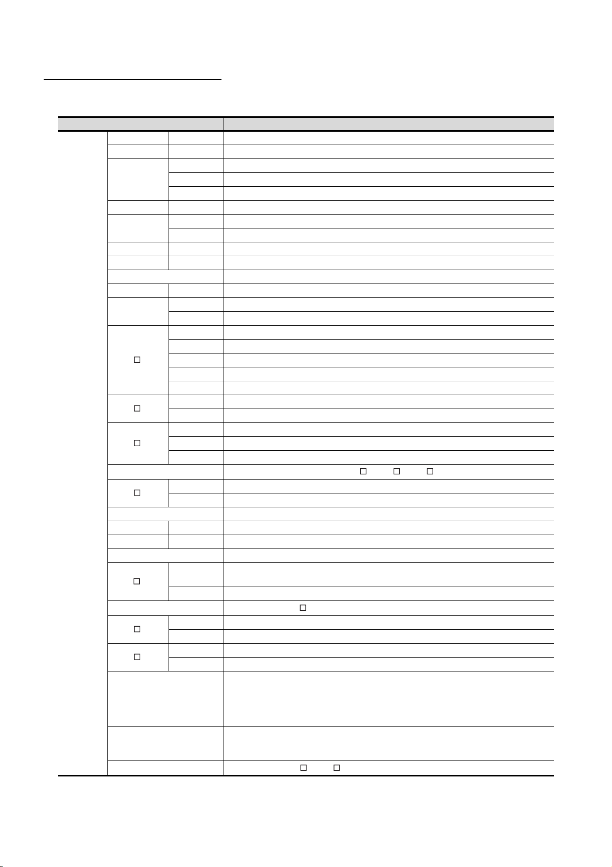
ABBREVIATIONS AND GENERIC TERMS
GOT
Abbreviations and generic terms Description
GT1695 GT1695M-X Abbreviation of GT1695M-XTBA, GT1695M-XTBD
GT1685 GT1685M-S Abbreviation of GT1685M-STBA, GT1685M-STBD
GT1675M-S Abbrevuation GT1575-STBA, GT1575-STBD
GOT1000
Series
GT1675
GT1672 GT1672-VN Abbreviation of GT1672-VNBA, GT1672-VNBD
GT1665
GT1662 GT1662-VN Abbreviation of GT1662-VNBA, GT1662-VNBD
GT1655 GT1655-V Abbreviation of GT1655-VTBD
GT16 Abbreviation of GT1695, GT1685, GT1675, GT1672, GT1665, GT1662, GT1655, GT16 Handy GOT
GT1595 GT1595-X Abbreviation of GT1595-XTBA, GT1595-XTBD
GT1585
GT157
GT156
GT155
GT15
GT145
GT14 Abbreviation of GT1455-Q, GT1450-Q
GT1275 GT1275-V Abbreviation of GT1275-VNBA, GT1275-VNBD
GT1265 GT1265-V Abbreviation of GT1265-VNBA, GT1265-VNBD
GT12 Abbreviation of GT1275, GT1265
GT115
GT11
GT105
GT104
GT1030
GT1020
GT10
GT1675M-V Abbreviation of GT1675M-VTBA, GT1675M-VTBD
GT1675-VN Abbreviation of GT1675-VNBA, GT1675-VNBD
GT1665M-S Abbreviation of GT1665M-STBA, GT1665M-STBD
GT1665M-V Abbreviation of GT1665M-VTBA, GT1665M-VTBD
GT1585V-S Abbreviation of GT1585V-STBA, GT1585V-STBD
GT1585-S Abbreviation of GT1585-STBA, GT1585-STBD
GT1575V-S Abbreviation of GT1575V-STBA, GT1575V-STBD
GT1575-S Abbreviation of GT1575-STBA, GT1575-STBD
GT1575-V Abbreviation of GT1575-VTBA, GT1575-VTBD
GT1575-VN Abbreviation of GT1575-VNBA, GT1575-VNBD
GT1572-VN Abbreviation of GT1572-VNBA, GT1572-VNBD
GT1565-V Abbreviation of GT1565-VTBA, GT1565-VTBD
GT1562-VN Abbreviation of GT1562-VNBA, GT1562-VNBD
GT1555-V Abbreviation of GT1555-VTBD
GT1555-Q Abbreviation of GT1555-QTBD, GT1555-QSBD
GT1550-Q Abbreviation of GT1550-QLBD
GT1455-Q Abbreviation of GT1455-QTBDE, GT1455-QTBD
GT1450-Q Abbreviation of GT1450-QLBDE, GT1450-QLBD
GT1155-Q
GT1150-Q Abbreviation of GT1150-QLBDQ, GT1150-QLBDA, GT1150-QLBD
GT1055-Q Abbreviation of GT1055-QSBD
GT1050-Q Abbreviation of GT1050-QBBD
GT1045-Q Abbreviation of GT1045-QSBD
GT1040-Q Abbreviation of GT1040-QBBD
Abbreviation of GT1595, GT1585, GT157 , GT156 , GT155
Abbreviation of GT1155-QTBDQ, GT1155-QSBDQ, GT1155-QTBDA, GT1155-QSBDA,
GT1155-QTBD, GT1155-QSBD
Abbreviation of GT115 , Handy GOT
Abbreviation of GT1030-LBD, GT1030-LBD2, GT1030-LBL, GT1030-LBDW, GT1030-LBDW2,
GT1030-LBLW, GT1030-LWD, GT1030-LWD2, GT1030-LWL, GT1030-LWDW, GT1030-LWDW2,
GT1030-LWLW, GT1030-HBD, GT1030-HBD2, GT1030-HBL, GT1030-HBDW, GT1030-HBDW2,
GT1030-HBLW, GT1030-HWD, GT1030-HWD2, GT1030-HWL, GT1030-HWDW, GT1030-HWDW2,
GT1030-HWLW
Abbreviation of GT1020-LBD, GT1020-LBD2, GT1020-LBL, GT1020-LBDW, GT1020-LBDW2,
GT1020-LBLW, GT1020-LWD, GT1020LWD2, GT1020-LWL, GT1020-LWDW, GT1020-LWDW2,
GT1020-LWLW
Abbreviation of GT105 , GT104 , GT1030, GT1020
A - 24
Page 27

Abbreviations and generic terms Description
GT16
Handy
GOT
GOT1000
Series
GOT900 Series Abbreviation of GOT-A900 Series, GOT-F900 Series
GOT800 Series Abbreviation of GOT-800 Series
Handy
GOT
GT11
Handy
GOT
GT SoftGOT1000 Abbreviation of GT SoftGOT1000
GT1665HS-V
GT1155HS-Q
GT1150HS-Q
Abbreviation of GT1665HS-VTBD
Abbreviation of GT1155HS-QSBD
Abbreviation of GT1150HS-QLBD
Communication unit
Abbreviations and generic terms Description
Bus connection unit
Serial communication unit GT15-RS2-9P, GT15-RS4-9S, GT15-RS4-TE
RS-422 Conversion Unit GT15-RS2T4-9P, GT15-RS2T4-25P
Ethernet communication unit GT15-J71E71-100
MELSECNET/H communication unit GT15-J71LP23-25, GT15-J71BR13
MELSECNET/10 communication unit
CC-Link IE Controller Network communication
unit
CC-Link IE Field Network communication unit GT15-J71GF13-T2
CC-Link communication unit
Interface converter unit GT15-75IF900
Serial multi-drop connection unit GT01-RS4-M
Connector conversion adapter GT10-9PT5S
RS-232/485 signal conversion adapter GT14-RS2T4-9P
*1 A9GT-QJ71LP23+GT15-75IF900 set
*2 A9GT-QJ71BR13+GT15-75IF900 set
*3 A8GT-J61BT13+GT15-75IF900 set
GT15-QBUS, GT15-QBUS2, GT15-ABUS, GT15-ABUS2, GT15-75QBUSL,
GT15-75QBUS2L, GT15-75ABUSL, GT15-75ABUS2L
*1
GT15-75J71LP23-Z
GT15-J71GP23-SX
GT15-J61BT13, GT15-75J61BT13-Z
, GT15-75J71BR13-Z
*2
*3
Option unit
Abbreviations and generic terms Description
Printer unit GT15-PRN
Video input unit GT16M-V4, GT15V-75V4
Video/RGB unit
Multimedia unit GT16M-MMR
CF card unit GT15-CFCD
CF card extension unit
External I/O unit GT15-DIO, GT15-DIOR
Sound output unit GT15-SOUT
Fingerprint unit GT15-80FPA
RGB input unit GT16M-R2, GT15V-75R1
Video/RGB input unit GT16M-V4R1, GT15V-75V4R1
RGB output unit GT16M-ROUT, GT15V-75ROUT
*1
*1 GT15-CFEX+GT15-CFEXIF+GT15-C08CF set
GT15-CFEX-C08SET
A - 25
Page 28

Option
Abbreviations and generic terms Description
Memory card
Memory card adaptor GT05-MEM-ADPC
Option function board
Battery GT15-BAT, GT11-50BAT
Protective Sheet
Protective cover for oil
USB environmental protection cover GT16-UCOV, GT16-50UCOV, GT15-UCOV, GT14-50UCOV, GT11-50UCOV
Stand GT15-90STAND, GT15-80STAND, GT15-70STAND, A9GT-50STAND, GT05-50STAND
Attachment
Backlight
Multi-color display board GT15-XHNB, GT15-VHNB
Connector conversion box GT11H-CNB-37S, GT16H-CNB-42S
Emergency stop sw guard cover GT11H-50ESCOV, GT16H-60ESCOV
Memory loader GT10-LDR
Memory board GT10-50FMB
Panel-mounted USB port extension GT14-C10EXUSB-4S, GT10-C10EXUSB-5S
CF card
SD card L1MEM-2GBSD, L1MEM-4GBSD
GT05-MEM-16MC, GT05-MEM-32MC, GT05-MEM-64MC, GT05-MEM-128MC,
GT05-MEM-256MC, GT05-MEM-512MC, GT05-MEM-1GC, GT05-MEM-2GC,
GT05-MEM-4GC, GT05-MEM-8GC, GT05-MEM-16GC
GT16-MESB, GT15-FNB, GT15-QFNB, GT15-QFNB16M,
GT15-QFNB32M, GT15-QFNB48M, GT11-50FNB, GT15-MESB48M
GT16-90PSCB, GT16-90PSGB, GT16-90PSCW, GT16-90PSGW,
GT16-80PSCB, GT16-80PSGB, GT16-80PSCW, GT16-80PSGW,
GT16-70PSCB, GT16-70PSGB, GT16-70PSCW, GT16-70PSGW,
For GT16
For GT15
For GT14 GT14-50PSCB, GT14-50PSGB, GT14-50PSCW, GT14-50PSGW
For GT12 GT11-70PSCB, GT11-65PSCB
For GT11 GT11-50PSCB, GT11-50PSGB, GT11-50PSCW, GT11-50PSGW, GT11H-50PSC
For GT10
GT05-90PCO, GT05-80PCO, GT05-70PCO, GT05-60PCO, GT05-50PCO,
GT16-50PCO, GT10-40PCO, GT10-30PCO, GT10-20PCO
GT15-70ATT-98, GT15-70ATT-87, GT15-60ATT-97, GT15-60ATT-96,
GT15-60ATT-87, GT15-60ATT-77, GT15-50ATT-95W, GT15-50ATT-85
GT16-90XLTT, GT16-80SLTT, GT16-70SLTT, GT16-70VLTT, GT16-70VLTTA, GT16-70VLTN,
GT16-60SLTT, GT16-60VLTT, GT16-60VLTN, GT15-90XLTT, GT15-80SLTT, GT15-70SLTT,
GT15-70VLTT, GT15-70VLTN, GT15-60VLTT, GT15-60VLTN
GT16-60PSCB, GT16-60PSGB, GT16-60PSCW, GT16-60PSGW,
GT16-50PSCB, GT16-50PSGB, GT16-50PSCW, GT16-50PSGW,
GT16-90PSCB-012, GT16-80PSCB-012, GT16-70PSCB-012,
GT16-60PSCB-012, GT16-50PSCB-012, GT16H-60PSC
GT15-90PSCB, GT15-90PSGB, GT15-90PSCW, GT15-90PSGW,
GT15-80PSCB, GT15-80PSGB, GT15-80PSCW, GT15-80PSGW,
GT15-70PSCB, GT15-70PSGB, GT15-70PSCW, GT15-70PSGW,
GT15-60PSCB, GT15-60PSGB, GT15-60PSCW, GT15-60PSGW,
GT15-50PSCB, GT15-50PSGB, GT15-50PSCW, GT15-50PSGW
GT10-50PSCB, GT10-50PSGB, GT10-50PSCW, GT10-50PSGW,
GT10-40PSCB, GT10-40PSGB, GT10-40PSCW, GT10-40PSGW,
GT10-30PSCB, GT10-30PSGB, GT10-30PSCW, GT10-30PSGW,
GT10-20PSCB, GT10-20PSGB, GT10-20PSCW, GT10-20PSGW
A - 26
Page 29
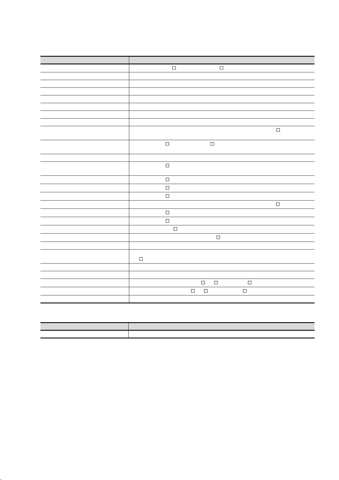
Software
Abbreviations and generic terms Description
GT Works3
GT Designer3 Abbreviation of screen drawing software GT Designer3 for GOT1000 series
GT Simulator3 Abbreviation of screen simulator GT Simulator3 for GOT1000/GOT900 series
GT SoftGOT1000 Abbreviation of monitoring software GT SoftGOT1000
GT Converter2 Abbreviation of data conversion software GT Converter2 for GOT1000/GOT900 series
GT Designer2 Classic Abbreviation of screen drawing software GT Designer2 Classic for GOT900 series
GT Designer2 Abbreviation of screen drawing software GT Designer2 for GOT1000/GOT900 series
iQ Works Abbreviation of iQ Platform compatible engineering environment MELSOFT iQ Works
MELSOFT Navigator
GX Works2
GX Simulator2 Abbreviation of GX Works2 with the simulation function
GX Simulator
GX Developer
GX LogViewer
PX Developer
MT Works2
MT Developer
MR Configurator2
MR Configurator
FR Configurator
NC Configurator Abbreviation of CNC parameter setting support tool NC Configurator
FX Configurator-FP
FX Configurator-EN Abbreviation of FX3U-ENET type Ethernet module setting software (SW1D5C-FXENET-E)
RT ToolBox2 Abbreviation of robot program creation software (3D-11C-WINE)
MX Component
MX Sheet
LCPU Logging Configuration Tool Abbreviation of LCPU Logging Configuration Tool (SW1DNN-LLUTL-E)
Abbreviation of the SW DNC-GTWK3-E and SW DNC-GTWK3-EA
Generic term for integrated development environment software included in the SW DNC-IQWK (iQ
Platform compatible engineering environment MELSOFT iQ Works)
Abbreviation of SW DNC-GXW2-E and SW DNC-GXW2-EA type programmable controller
engineering software
Abbreviation of SW D5C-LLT-E(-EV) type ladder logic test tool function software packages
(SW5D5C-LLT (-EV) or later versions)
Abbreviation of SW D5C-GPPW-E(-EV)/SW D5F-GPPW-E type software package
Abbreviation of SW DNN-VIEWER-E type software package
Abbreviation of SW D5C-FBDQ-E type FBD software package for process control
Abbreviation of motion controller engineering environment MELSOFT MT Works2 (SW DNC-MTW2-E)
Abbreviation of SW RNC-GSV type general start-up support software for motion controller Q series
Abbreviation of SW DNC-MRC2-E type Servo Configuration Software
Abbreviation of MRZJW -SETUP type servo set up software
Abbreviation of Inverter Setup Software (FR-SW -SETUP-WE)
Abbreviation of parameter setting, monitoring, and testing software packages for FX3U-20SSC-H
(SW D5C-FXSSC-E)
Abbreviation of MX Component Version (SW D5C-ACT-E, SW D5C-ACT-EA)
Abbreviation of MX Sheet Version (SW D5C-SHEET-E, SW D5C-SHEET-EA)
License key (for GT SoftGOT1000)
Abbreviations and generic terms Description
License key GT15-SGTKEY-U, GT15-SGTKEY-P
A - 27
Page 30

Others
Abbreviations and generic terms Description
IAI Abbreviation of IAI Corporation
AZBIL Abbreviation of Azbil Corporation (former Yamatake Corporation)
OMRON Abbreviation of OMRON Corporation
KEYENCE Abbreviation of KEYENCE CORPORATION
KOYO EI Abbreviation of KOYO ELECTRONICS INDUSTRIES CO., LTD.
SHARP Abbreviation of Sharp Manufacturing Systems Corporation
JTEKT Abbreviation of JTEKT Corporation
SHINKO Abbreviation of Shinko Technos Co., Ltd.
CHINO Abbreviation of CHINO CORPORATION
TOSHIBA Abbreviation of TOSHIBA CORPORATION
TOSHIBA MACHINE Abbreviation of TOSHIBA MACHINE CO., LTD.
HITACHI IES Abbreviation of Hitachi Industrial Equipment Systems Co., Ltd.
HITACHI Abbreviation of Hitachi, Ltd.
FUJI FA Abbreviation of Fuji Electric FA Components & Systems Co., Ltd.
PANASONIC Abbreviation of Panasonic Corporation
FUJI SYS Abbreviation of Fuji Electric Systems Co., Ltd.
YASKAWA Abbreviation of YASKAWA Electric Corporation
YOKOGAWA Abbreviation of Yokogawa Electric Corporation
ALLEN-BRADLEY Abbreviation of Allen-Bradley products manufactured by Rockwell Automation, Inc.
GE FANUC Abbreviation of GE Fanuc Automation Corporation
LS IS Abbreviation of LS Industrial Systems Co., Ltd.
SCHNEIDER Abbreviation of Schneider Electric SA
SICK Abbreviation of SICK AG
SIEMENS Abbreviation of Siemens AG
RKC Abbreviation of RKC INSTRUMENT INC.
HIRATA Abbreviation of Hirata Corporation
MURATEC Abbreviation of Muratec products manufactured by Muratec Automation Co., Ltd.
α2 Abbreviation of α2 Simple Application Controller
PLC Generic term for programmable logic controllers of each manufacturer
Temperature controller Generic term for temperature controllers of each manufacturer
Indicating controller Generic term for indicating controllers of each manufacturer
Control equipment Generic term for control equipment manufactured by each corporation
Controller Generic term for controllers of each manufacturer
PC CPU module Abbreviation of PC CPU Unit manufactured by CONTEC CO., LTD
GOT (server) Abbreviation of GOTs that use the server function
GOT (client) Abbreviation of GOTs that use the client function
®
Windows
Intelligent function module
MODBUS
MODBUS
font
®
/RTU Generic term for protocols designed to use MODBUS® protocol messages on a serial communication
®
/TCP Generic term for the protocol designed to use MODBUS® protocol messages on a TCP/IP network
Abbreviation of TrueType font (Other than the True Type fonts settable with GT Designer3) and
OpenType font available for Windows
Indicates the modules other than the PLC CPU, power supply module and I/O module that are mounted
to the base unit
®
A - 28
Page 31
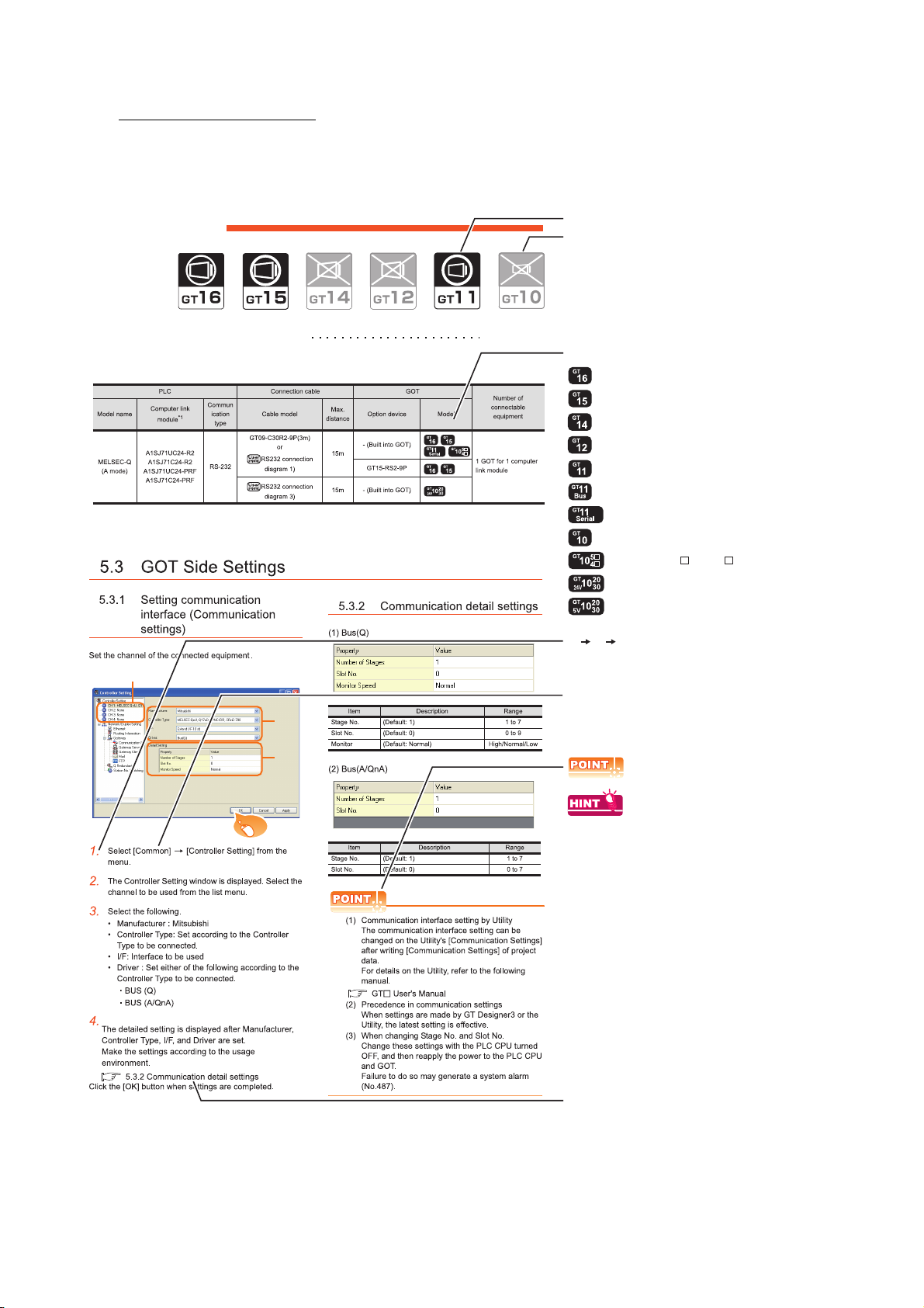
HOW TO READ THIS MANUAL
Not connectable model name
Connectable model name
BUS CONNECTION
5.1 Connectable Model List 5 - 2
Applicable model name
Shows GT16.
Shows GT15.
Shows GT11.
Shows GT11 (BUS).
Shows GT10.
Shows GT11 (SERIAL).
Shows GT1020,GT1030 (input power supply : 24V).
Shows GT1020,GT1030 (input power supply : 5V).
Shows GT105 ,GT104 .
Indicates the location of related content.
Indicates the operation steps.
[ ]: Indicates the setting items displayed on
the software and GOT screen.
1. 2. 3.
…
Refers to the information required.
Refers to information useful
for operation.
2.
3.
4.
Click!
Shows GT14.
Shows GT12.
Symbols
Following symbols are used in this manual.
Since the above page was created for explanation purpose, it differs from the actual page.
A - 29
Page 32
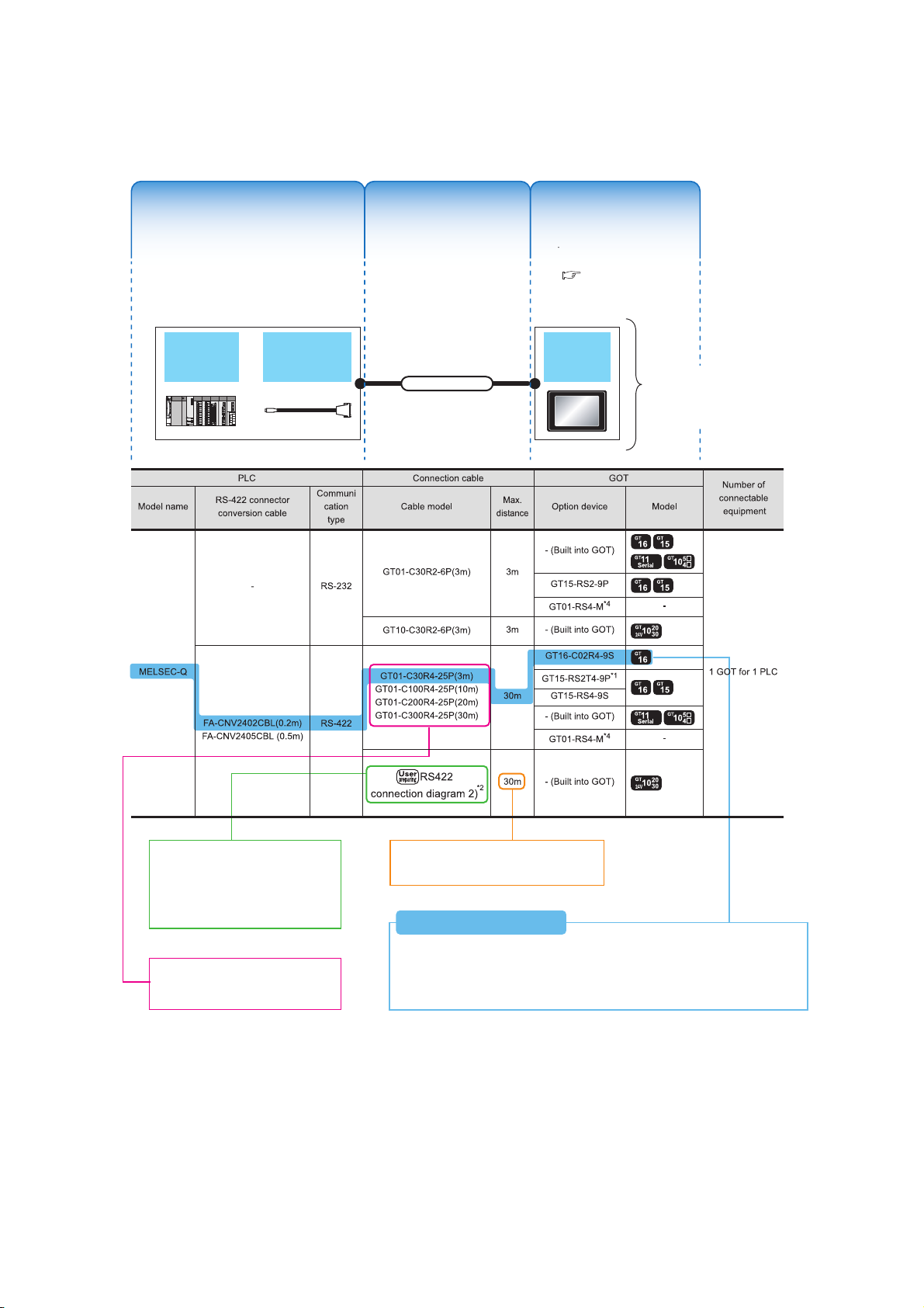
About system configuration
The configuration of The configuration of
equipment connected equipment connected
to GOT is shown.to GOT is shown.
The cable connecting The cable connecting
the GOT to the the GOT to the
equipment is shown.equipment is shown.
The configuration of The configuration of
the GOT connected to the GOT connected to
equipment is shown.equipment is shown.
RS-422 connector
conversion Cable
QCPU GOT
Connection cable
A representative example
of the system configuration
is described with an
illustration.
Indicates the connection diagram
number of cables to be prepared by
the user.
Refer to the connection diagram
section in each chapter.
Indicates the commercially available
cable models that can be used.
Indicates the maximum distance between
the PLC and GOT.
1) Connect the RS-422 conversion cable [FA-CNV2402CBL] to the [MELSEC-Q].
2) Connect the option [GT16-C02R4-9S] to [GT16].
3) Connect [MELSEQ-Q] and [GT16] with the connection cable [GT01-C30R4-25P].
System Configuration ExamplesSystem Configuration Examples
(When connecting the PLC [MELSEC-Q] and GT16, with RS-422 cable)
System Configuration Examples
The configuration of
equipment connected
to GOT is shown.
The cable connecting
the GOT to the
equipment is shown.
The configuration of
the GOT connected to
equipment is shown.
For the option devices,
refer to the following.
1.3 Option Devices for
the Respective
Connection
The following describes the system configuration of each connection included in this manual.
Since the above page was created for explanation purpose, it differs from the actual page.
A - 30
Page 33

1
1
1.PREPARATORY PROCEDURES
FOR MONITORING
1.1 Setting the Communication Interface . . . . . . . . . . . . . . . . . . 1 - 3
1.2 Writing the Project Data and OS onto the GOT . . . . . . . . . 1 - 15
1.3 Option Devices for the Respective Connection . . . . . . . . . 1 - 17
1.4 Connection Cables for the Respective Connection . . . . . . 1 - 26
1.5 Verifying GOT Recognizes Connected Equipment . . . . . . 1 - 34
1.6 Checking for Normal Monitoring. . . . . . . . . . . . . . . . . . . . . 1 - 39
PREPARATORY
PROCEDURES FOR
MONITORING
2
DEVICE RANGE
THAT CAN BE SET
3
ACCESS RANGE
FOR MONITORING
4
HOW TO MONITOR
REDUNTANT
SYSTEM
5
1 - 1
BUS CONNECTION
6
DIRECT
CONNECTION TO
CPU
7
COMPUTER LINK
CONNECTION
8
ETHERNET
CONNECTION
Page 34

1. PREPARATORY PROCEDURES FOR
MONITORING
The following shows the procedures to be taken before monitoring and corresponding reference sections.
Setting the communication interface
Determine the connection type and channel No. to be used, and
perform the communication setting.
Writing the project data and OS
Write the standard monitor OS, communication driver, option
OS, project data and communication settings onto the GOT.
Verifying the project data and OS
Verify the standard monitor OS, communication driver, option
OS, project data and communication settings are properly
written onto the GOT.
Attaching the communication unit and
connecting the cable
Mount the optional equipment and prepare/connect the
connection cable according to the connection type.
1.1 Setting the Communication Interface
Each chapter GOT Side Settings
1.2.1 Writing the project data and OS onto the GOT
1.2.2 Checking the project data and OS writing on GOT
1.3 Option Devices for the Respective Connection
1.4 Connection Cables for the Respective Connection
Each chapter System Configuration
Each chapter Connection Diagram
1 - 2
Verifying GOT recognizes connected
equipment
Verify the GOT recognizes controllers on [Communication
Settings] of the Utility.
Verifying the GOT is monitoring normally
Verify the GOT is monitoring normally using Utility, Developer,
etc.
1. PREPARATORY PROCEDURES FOR MONITORING
1.5 Verifying GOT Recognizes Connected Equipment
1.6 Checking for Normal Monitoring
Page 35

1.1 Setting the Communication Interface
POINTPOINTPOINT
Set the communication interface of GOT and the connected equipment.
When using the GOT at the first time, make sure to set the channel of communication interface and the communication
driver before writing to GOT.
Set the communication interface of the GOT at [Controller Setting] and [I/F Communication Setting] in GT Designer3.
When using the parameter reflection function of MELSOFT Navigator.
The system configuration of MELSOFT Navigator can be reflected to the project of GT Designer3 using the
parameter function of MELSOFT Navigator.
For details of the parameter functions of MELSOFT Navigator, refer to the following.
Help of MELSOFT Navigator
(1) The color of the cells for the items which are reflected to GT Designer3 from MELSOFT Navigator changes to
green. Set items, which are displayed in green cells, from the MELSOFT Navigator. When changing in GT
Designer3, refer to the following (3).
1
PREPARATORY
PROCEDURES FOR
MONITORING
2
DEVICE RANGE
THAT CAN BE SET
3
ACCESS RANGE
FOR MONITORING
4
(2) When setting the communication interface for the connection with the iQ Works untargeted equipment, set
[Set with GT Designer3] to the channel connected at [Input Detailed Configuration Information] in MELSOFT
Navigator and make the settings at [Controller Setting] in GT Designer3.
(3) To make the items reflected from MELSOFT Navigator editable on GT Designer3, select the [Option] menu
and put a check mark at [Enable an editing of parameters set in MELSOFT Navigator] in the [iQ Works
Interaction] tab.
However, when the items set in MELSOFT Navigator are edited in GT Designer3, the interaction function with
MELSOFT Navigator is unavailable due to a mismatch with the system configuration of MELSOFT Navigator.
Eliminate mismatches using the parameter verification function etc. before using the interaction function of
MELSOFT Navigator.
HOW TO MONITOR
REDUNTANT
SYSTEM
5
BUS CONNECTION
6
DIRECT
CONNECTION TO
CPU
7
COMPUTER LINK
CONNECTION
8
1. PREPARATORY PROCEDURES FOR MONITORING
1.1 Setting the Communication Interface
1 - 3
ETHERNET
CONNECTION
Page 36

1.1.1 Setting connected equipment (Channel setting)
POINTPOINTPOINT
Set the channel of the equipment connected to the GOT.
Setting
1. Select [Common] [Controller Setting] from the menu.
2.
The Controller Setting dialog box appears. Select the channel No. to be used from the list menu.
3. Refer to the following explanations for the setting.
Channel No.2 to No.4
Use the channel No.2 to No.4 when using the Multi-channel function.
For details of the Multi-channel function, refer to the following.
Mitsubishi Products 21. MULTI-CHANNEL FUNCTION
1 - 4
1. PREPARATORY PROCEDURES FOR MONITORING
1.1 Setting the Communication Interface
Page 37

Setting item
This section describes the setting items of the Manufacturer, Controller Type, Driver and I/F.
When using the channel No.2 to No.4, put a check mark at [Use CH*].
1
PREPARATORY
PROCEDURES FOR
MONITORING
2
DEVICE RANGE
THAT CAN BE SET
3
ACCESS RANGE
FOR MONITORING
4
Item Description
Use CH* Select this item when setting the channel No.2 to No.4.
Manufacturer Select the manufacturer of the equipment to be connected to the GOT.
Typ e
I/F
Driver
Detail Setting
Select the type of the equipment to be connected to the GOT. For the settings, refer to the following.
(2)Setting [Controller Type]
Select the interface of the GOT to which the equipment is connected.For the settings, refer to the following.
(3)Setting [I/F]
Select the communication driver to be written to the GOT. For the settings, refer to the following.
(1)Setting [Driver]
Make settings for the transmission speed and data length of the communication driver.
Refer to each chapter of the equipment to be connected to the GOT.
(1) Setting [Driver]
The displayed items for a driver differ according to the settings [Manufacturer], [Controller Type] and [I/F].
When the driver to be set is not displayed, confirm if [Manufacturer], [Controller Type] and [I/F] are correct.
For the settings, refer to the following.
[Setting the communication interface] section in each chapter
HOW TO MONITOR
REDUNTANT
SYSTEM
5
BUS CONNECTION
6
DIRECT
CONNECTION TO
CPU
7
COMPUTER LINK
CONNECTION
8
1. PREPARATORY PROCEDURES FOR MONITORING
1.1 Setting the Communication Interface
1 - 5
ETHERNET
CONNECTION
Page 38

(2) Setting [Controller Type]
The types for the selection differs depending on the PLC to be used.
For the settings, refer to the following.
Type Model name
For GT16, GT15, GT14, GT12, GT11
MELSEC-Q(MULTI)/Q MOTION
For GT10
MELSEC-Q(MULTI)
For GT16, GT15, GT12
MELSEC-QnU/DC, Q17nD/M/NC/DR, CRnD-700
For GT14, GT11
MELSEC-QnU/DC, Q17nD/M/NC/DR
*1
For GT10
MELSEC-QnU/DC
*1*2
*1
Q00CPU
Q01CPU
Q02CPU
Q02HCPU
Q06HCPU
Q12HCPU
Q25HCPU
Q02PHCPU
Q06PHCPU
Q12PHCPU
Q25PHCPU
Q172CPU
Q173CPU
Q172CPUN
Q173CPUN
Q172HCPU
Q173HCPU
Q00UJCPU
Q00UCPU
Q01UCPU
Q02UCPU
Q03UDCPU
Q04UDHCPU
Q06UDHCPU
Q10UDHCPU
Q13UDHCPU
Q20UDHCPU
Q26UDHCPU
Q03UDECPU
Q04UDEHCPU
Q06UDEHCPU
Q10UDEHCPU
Q13UDEHCPU
Q20UDEHCPU
Q26UDEHCPU
Q50UDEHCPU
Q100UDEHCPU
Q03UDVCPU
Q04UDVCPU
Q06UDVCPU
Q13UDVCPU
Q26UDVCPU
Q12DCCPU-V
Q24DHCCPU-V
Typ e Model name
For GT16, GT15, GT12
*1*2
MELSEC-QnU/DC, Q17nD/M/NC/DR, CRnD-700
For GT14, GT11
*1
MELSEC-QnU/DC, Q17nD/M/NC/DR
*1
For GT10
MELSEC-QnU/DC
For GT16, GT15, GT12
*1*2
MELSEC-QnA/Q/QS, MELDAS C6*
For GT14, GT11
*1
MELSEC-QnA/Q, MELDAS C6*
*1
For GT10
MELSEC-QnA/Q
MELSEC-L
*1 When using the multiple CPU system
When using the GOT to monitor the multiple CPU system of
other station, select [MELSEC-Q(Multi)/Q-Motion], or
[MELSEC-QnU/DC,Q17nD/M/NC/DR,CRnD-700] for the
type regardless of the host PLC CPU type.
*2 When connecting to the remote I/O station in the
MELSECNET/H network system, set the type to [MELSECQnA/Q/QS, MELDAS C6 *].
Q172DCPU
Q173DCPU
Q172DCPU-S1
Q173DCPU-S1
Q172DSCPU
Q173DSCPU
Q170MCPU
MR-MQ100
CNC C70
(Q173NCCPU)
CRnQ-700
(Q172DRCPU)
CRnD-700
Q00JCPU
Q00CPU
Q01CPU
Q02CPU
Q02HCPU
Q06HCPU
Q12HCPU
Q25HCPU
Q02PHCPU
Q06PHCPU
Q12PHCPU
Q25PHCPU
Q12PRHCPU
Q25PRHCPU
QS001CPU
*3
Q2ACPU
Q2ACPU-S1
Q3ACPU
Q4ACPU
Q4ARCPU
Q2ASCPU
Q2ASCPU-S1
Q2ASHCPU
Q2ASHCPU-S1
MELDAS C6 (FCA C6)
MELDAS C64 (FCA C64)
L02CPU
L26CPU
L26CPU-BT
L02CPU-P
L26CPU-PBT
L02SCPU
NZ2GF-ETB
1 - 6
1. PREPARATORY PROCEDURES FOR MONITORING
1.1 Setting the Communication Interface
Page 39

MELSEC-A
Typ e Model name
A2UCPU
A2UCPU-S1
A3UCPU
A4UCPU
A2ACPU
A2ACPUP21
A2ACPUR21
A2ACPU-S1
A2ACPUP21-S1
A2ACPUR21-S1
A3ACPU
A3ACPUP21
A3ACPUR21
A1NCPU
A1NCPUP21
A1NCPUR21
A2NCPU
A2NCPUP21
A2NCPUR21
A2NCPU-S1
A2NCPUP21-S1
A2NCPUR21-S1
A3NCPU
A3NCPUP21
A3NCPUR21
A2USCPU
A2USCPU-S1
A2USHCPU-S1
A1SCPU
A1SCPUC24-R2
A1SHCPU
A2SCPU
A2SCPU-S1
A2SHCPU
A2SHCPU-S1
A1SJCPU
A1SJCPU-S3
A1SJHCPU
A0J2HCPU
A0J2HCPUP21
A0J2HCPUR21
A0J2HCPU-DC24
A2CCPU
A2CCPUP21
A2CCPUR21
A2CCPUC24
A2CCPUC24-PRF
A2CJCPU-S3
A1FXCPU
A273UCPU
A273UHCPU
A273UHCPU-S3
Type Model name
A373UCPU
A373UCPU-S3
A171SCPU
A171SCPU-S3
A171SCPU-S3N
MELSEC-A
MELSEC-FX
MELSEC-FX(Ethernet)
MELSEC-WS
MELSERVO-J2M-P8A
MELSERVO-J2M-*DU
MELSERVO-J2S-*A MELSERVO-J2S-*A
MELSERVO-J2S-*CP
MELSERVO-J2S-*CL
MELSERVO-J3-*A MELSERVO-J3-*A
MELSERVO-J3-*T MELSERVO-J3-*T
MELSERVO-J4-*A MELSERVO-J4-*A
FREQROL 500/700 Series
A171SHCPU
A171SHCPUN
A172SHCPU
A172SHCPUN
A173UHCPU
A173UHCPU-S1
0
FX
FX0S
FX0N
FX1
FX2
FX2C
FX1S
FX1N
FX2N
FX1NC
FX2NC
FX3G
FX3GC
FX3U
FX3UC
FX
3U
FX3UC
WS0-CPU0
WS0-CPU1
MELSERVO-J2M-P8A
MELSERVO-J2M-*DU
MELSERVO-J2S-*CP
MELSERVO-J2S-*CL
FREQROL-S500
FREQROL-S500E
FREQROL-E500
FREQROL-F500
FREQROL-F500L
FREQROL-F500J
FREQROL-A500
FREQROL-A500L
FREQROL-V500
FREQROL-V500L
FREQROL-E700
FREQROL-F700
FREQROL-F700P
FREQROL-F700PJ
FREQROL-A700
1
PREPARATORY
PROCEDURES FOR
MONITORING
2
DEVICE RANGE
THAT CAN BE SET
3
ACCESS RANGE
FOR MONITORING
4
HOW TO MONITOR
REDUNTANT
SYSTEM
5
BUS CONNECTION
6
DIRECT
CONNECTION TO
CPU
7
COMPUTER LINK
CONNECTION
8
1. PREPARATORY PROCEDURES FOR MONITORING
1.1 Setting the Communication Interface
1 - 7
ETHERNET
CONNECTION
Page 40

(3) Setting [I/F]
3rd stage
Extension interface 1
Extension interface 2
Standard interface 1
(RS-232 interface built in the GOT)
2nd stage
1st stage
Standard interface 2
(USB interface built in the GOT)
(Example: In the case of the GT1685)
Standard interface 3
(RS-422/485 interface built in the GOT)
Standard interface 4
(Ethernet interface built in the GOT)
The interface differs depending on the GOT to be used.
Set the I/F according to the connection and the position of communication unit to be mounted onto the GOT.
(a) GT16
(b) GT15
3rd stage
2nd stage
1st stage
(Example: In the case of the GT1575)
Extension interface 1
Extension interface 2
Standard interface 1
(RS-232 interface built in the GOT)
Standard interface 2
(USB interface built in the GOT)
1 - 8
1. PREPARATORY PROCEDURES FOR MONITORING
1.1 Setting the Communication Interface
Page 41
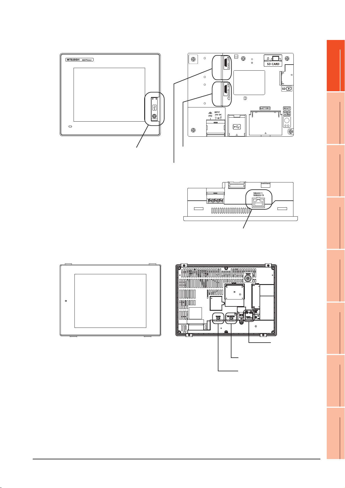
(c) GT14
Standard interface 4
(GOT built-in Ethernet interface)
Standard interface 3
(GOT built-in USB interface)
[Front view]] [Rear view]
[Under view]
Standard interface 1
(GOT built-in RS-422 interface)
Standard interface 2
(GOT built-in RS-232 interface)
Standard interface 1
(GOT built-in RS-422 interface)
Standard interface 2
(GOT built-in RS-232 interface)
Standard interface 4
(GOT built-in Ethernet interface)
[Front view] [Rear view]
1
PREPARATORY
PROCEDURES FOR
MONITORING
2
DEVICE RANGE
THAT CAN BE SET
3
ACCESS RANGE
FOR MONITORING
4
(d) GT12
HOW TO MONITOR
REDUNTANT
SYSTEM
5
BUS CONNECTION
6
DIRECT
CONNECTION TO
CPU
7
COMPUTER LINK
CONNECTION
8
1. PREPARATORY PROCEDURES FOR MONITORING
1.1 Setting the Communication Interface
1 - 9
ETHERNET
CONNECTION
Page 42

(e) GT11
Standard interface 3
(GOT built-in USB interface)
[Front view] [Rear view]
Standard interface 1
(GOT built-in RS-422 interface)
Standard interface 2
(GOT built-in RS-232 interface)
Standard interface 3
(GOT built-in USB interface)
Standard interface 2
(GOT built-in RS-232 interface)
Standard interface 1
(GOT built-in Bus interface)
[Front view] [Rear view]
•GT11 Serial
•GT11 Bus
1 - 10
1. PREPARATORY PROCEDURES FOR MONITORING
1.1 Setting the Communication Interface
Page 43
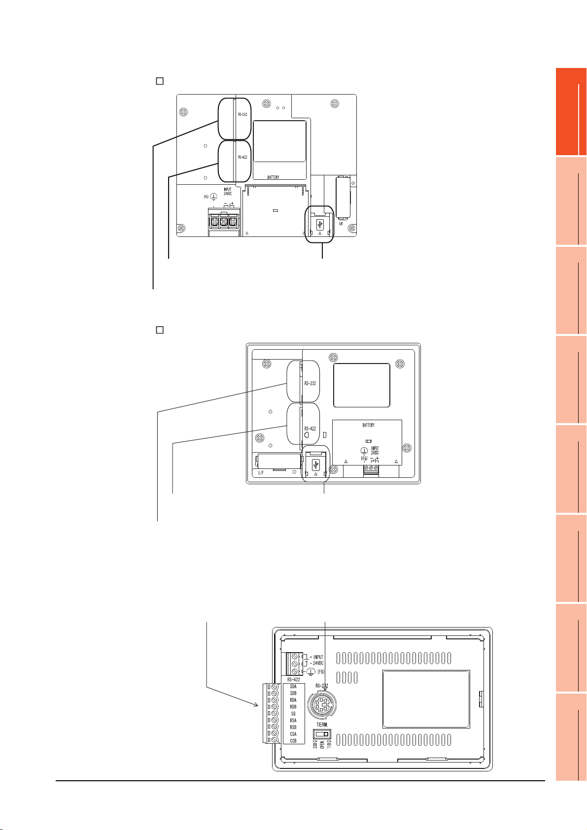
(f) GT105
Standard interface 1
(GOT built-in RS-422 interface)
Standard interface 2
(GOT built-in RS-232 interface)
Standard interface 3
(GOT built-in USB interface)
[Rear view]
Standard interface 1
(GOT built-in RS-422 interface)
or (GOT built-in RS-232 interface)
Standard interface 2
(GOT built-in RS-232 interface)
(g) GT104
1
PREPARATORY
PROCEDURES FOR
MONITORING
2
DEVICE RANGE
THAT CAN BE SET
3
ACCESS RANGE
FOR MONITORING
4
(h) GT1020, GT1030
Standard interface 1
(GOT built-in RS-422 interface)
Standard interface 2
(GOT built-in RS-232 interface)
Standard interface 3
(GOT built-in USB interface)
HOW TO MONITOR
REDUNTANT
SYSTEM
5
BUS CONNECTION
6
DIRECT
CONNECTION TO
CPU
7
COMPUTER LINK
CONNECTION
8
1. PREPARATORY PROCEDURES FOR MONITORING
1.1 Setting the Communication Interface
1 - 11
ETHERNET
CONNECTION
Page 44

1.1.2 I/F communication setting
POINTPOINTPOINT
This function displays the list of the GOT communication interfaces.
Set the channel and the communication driver to the interface to be used.
Setting
1. Select [Common] [I/F Communication Setting] from the menu.
2. The I/F Communication Setting dialog box appears. Make the settings with reference to the following explanation.
When using the parameter reflection function of MELSOFT Navigator.
When setting [Controller Setting] in GT Designer3 using the parameter function of MELSOFT Navigator, all of I/F
Communication Setting are grayout and cannot be edited.Set these items at [Controller Setting] or [Peripheral Unit
Setting].
1 - 12
1. PREPARATORY PROCEDURES FOR MONITORING
1.1 Setting the Communication Interface
Page 45

Setting item
The following describes the setting items for the standard I/F setting and extension I/F setting.
1
PREPARATORY
PROCEDURES FOR
MONITORING
2
DEVICE RANGE
THAT CAN BE SET
3
ACCESS RANGE
FOR MONITORING
4
Item Description
Standard I/F setting
Set channel No. and drivers to the GOT standard interfaces.
GT16, GT14, GT12: Standard I/F-1, Standard I/F-2, Standard I/F-3, Standard I/F-4
GT15, GT1030, GT1020: Standard I/F-1, Standard I/F-2
GT11, GT105 , GT104 : Standard I/F-1, Standard I/F-2, Standard I/F-3
Set the CH No. according to the intended purpose.
The number of channels differs depending on the GOT to be used.
0: Not used
1 to 4: Used for connecting a controller of channel No. 1 to 4 set in Setting connected equipment (Channel
setting)
CH No.
I/F The communication type of the GOT standard interface is displayed.
Driver
Detail Setting
RS232 Setting
8: Used for fingerprint authentication, barcode function, RFID function, remote personal computer operation
(serial), report function (when using the serial printer), hard copy function (when using the serial printer) or GOT
(extended computer)
9: Used for connecting Host (PC) or Host (modem)
*: Used for remote personal computer operation (Ethernet), Ethernet download, gateway function or MES
interface function
Multi: Used for Ethernet multiple connection
Set the driver for the device to be connected.
None Host (Personal computer) Each communication driver for connected devices
Make settings for the transmission speed and data length of the communication driver.
Refer to each chapter of the equipment to be connected to the GOT.
To validate the 5V power supply function in RS232, mark the [Enable the 5V power supply] checkbox.
The RS232 setting is invalid in the following cases.
• CH No. of [I/F-1: RS232] is [9] in GT15 and 16.
• CH No. of [I/F-1: RS232] is [9] or [8] in GT14.
• For GT12, GT11 and GT10
(Continued to next page)
HOW TO MONITOR
REDUNTANT
SYSTEM
5
BUS CONNECTION
6
DIRECT
CONNECTION TO
CPU
7
COMPUTER LINK
CONNECTION
8
1. PREPARATORY PROCEDURES FOR MONITORING
1.1 Setting the Communication Interface
1 - 13
ETHERNET
CONNECTION
Page 46

POINTPOINTPOINT
Item Description
Extension I/F setting Set the communication unit attached to the extension interface of the GOT.
Set the CH No. according to the intended purpose.
The number of channels differs depending on the GOT to be used.
0: Not used
1 to 4: Used for connecting a controller of channel No. 1 to 4 set in Setting connected equipment (Channel
setting)
CH No.
Driver
Detail Setting
5 to 7: Used for barcode function, RFID function, remote personal computer operation (serial), report function
(when using the serial printer) or hard copy function (when using the serial printer)
* : Used for remote personal computer operation (Ethernet), video display function, multimedia function,
operation panel function, external I/O function, RGB display function, report function (when using a
PictBridge compatible printer), hard copy function (when using a PictBridge compatible printer), sound
output function, functions with the CF card unit or CF card extension unit, Ethernet download, gateway
function or MES interface function
Set the driver for the device to be connected.
None Each driver for connected devices
Make settings for the transmission speed and data length of the communication driver.
Refer to each chapter of the equipment to be connected to the GOT.
Channel No., drivers, [RS232 Setting]
(1) Channel No.2 to No.4
Use the channel No.2 to No.4 when using the Multi-channel function.
For details of the Multi-channel function, refer to the following.
Mitsubishi Products 21. MULTI-CHANNEL FUNCTION
(2) Drivers
The displayed items for a driver differ according to the settings [Manufacturer], [Controller Type] and [I/F].
When the driver to be set is not displayed, confirm if [Manufacturer], [Controller Type] and [I/F] are correct.
[Setting the communication] section in each chapter
(3) [RS232 Setting] of GT14
Do not use [RS232 Setting] of GT14 for other than the 5V power feeding to the RS-232/485 signal conversion
adaptor.
For details, refer to the following manual.
GT14 User's Manual 7.11 RS-232/485 Signal Conversion Adaptor
1.1.3 Precautions
(1) When using the multiple CPU system
When using the GOT to monitor the multiple CPU system of other stations, select [MELSEC-Q(Multi)/Q-Motion]
or [MELSEC-QnU, Q17nD/M/NC/DR, CRnD-700] for the type, regardless of the host PLC CPU type (QCPU,
QnACPU, ACPU). When other models are selected, the setting of the CPU No. becomes unavailable.
(2) Precautions for changing model
(a) When devices that cannot be converted are included.
When setting of [Manufacturer] or [Controller Type] is changed, GT Designer3 displays the device that
cannot be converted (no corresponding device type, or excessive setting ranges as [??]. In this case, set
the device again.
(b) When the changed Manufacturer or Controller Type does not correspond to the network.
The network will be set to the host station.
(c) When the Manufacturer or Controller Type is changed to [None]
The GT Designer3 displays the device of the changed channel No. as [??]. In this case, set the device
again.
Since the channel No. is retained, the objects can be reused in other channel No. in a batch by using the
[Device Bach Edit], [CH No. Batch Edit] or [Device List].
1 - 14
1. PREPARATORY PROCEDURES FOR MONITORING
1.1 Setting the Communication Interface
Page 47

1.2 Writing the Project Data and OS onto the GOT
POINTPOINTPOINT
Write the standard monitor OS, communication driver, option OS, project data and communication settings onto the GOT.
For details on writing to GOT, refer to the following manual.
GT Designer3 Version Screen Design Manual
1.2.1 Writing the project data and OS onto the GOT
1
PREPARATORY
PROCEDURES FOR
MONITORING
2
DEVICE RANGE
THAT CAN BE SET
3
ACCESS RANGE
FOR MONITORING
4
1. Select [Communication] [Write to GOT…] from the menu.
2. The [Communication configuration] dialog box appears.
Set the communication setting between the GOT and the personal computer.
Click the [OK] button when settings are completed.
3. The [GOT Write] tab appears on the [Communicate with GOT] dialog box.
Select the [Project data, OS] radio button of the Write Data.
4. Check-mark a desired standard monitor OS, communication driver, option OS, extended function OS, and
Communication Settings and click the [GOT Write] button.
Writing communication driver onto GT10
When writing a communication driver onto the GT10 in which a Boot OS Ver. under F or a standard monitor OS
Ver. under 01.08.00 is written, turn on the GOT in the OS transfer mode.
For details, refer to the following manual.
GT10 User's Manual
(Operating of transmission mode)
HOW TO MONITOR
REDUNTANT
SYSTEM
5
BUS CONNECTION
6
DIRECT
CONNECTION TO
CPU
7
COMPUTER LINK
CONNECTION
8
Turn on the GOT while the bottom right corner is touched.
1. PREPARATORY PROCEDURES FOR MONITORING
1.2 Writing the Project Data and OS onto the GOT
1 - 15
ETHERNET
CONNECTION
Page 48

1.2.2 Checking the project data and OS writing on GOT
Confirm if the standard monitor OS, communication driver, option OS, project data and communication settings are
properly written onto the GOT by reading from GOT using GT Designer3.
For reading from the GOT, refer to the following manual.
GT Designer3 Version Screen Design Manual
1. Select [Communication] [Read from GOT…] from the menu.
2. The [Communication configuration] dialog box appears.
Set the communication setting between the GOT and the personal computer.
Click the [OK] button when settings are completed.
3. The [GOT Read] tab appears on the [Communicate with GOT] dialog box.
Select the [Drive information] radio button of the Read Data.
4. Click the [Info Reception] button.
5. Confirm that the project data and OS are written correctly onto the GOT.
1 - 16
1. PREPARATORY PROCEDURES FOR MONITORING
1.2 Writing the Project Data and OS onto the GOT
Page 49

1.3 Option Devices for the Respective Connection
The following shows the option devices to connect in the respective connection type.
For the specifications, usage and connecting procedure on option devices, refer to the respective device manual.
1.3.1 Communication module
Product name Model Specifications
GT15-QBUS
GT15-QBUS2
GT15-ABUS
GT15-ABUS2
Bus connection unit
GT15-75QBUSL
GT15-75QBUS2L
GT15-75ABUSL
GT15-75ABUS2L
GT15-RS2-9P RS-232 serial communication unit (D-sub 9-pin (male))
Serial communication module
RS-422 conversion unit
MELSECNET/H
Communication module
MELSECNET/10
Communication module
CC-Link IE Controller Network
communication unit
CC-Link IE Field Network
communication unit
CC-Link communication unit
Ethernet communication unit GT15-J71E71-100 Ethernet (100Base-TX) unit
GT15-RS4-9S RS-422/485 serial communication unit (D-sub 9-pin (female))
GT15-RS4-TE RS-422/485 serial communication unit (terminal block)
GT15-RS2T4-9P
GT15-RS2T4-25P RS-422 side connector 25-pin
GT15-J71LP23-25 Optical loop unit
GT15-J71BR13 Coaxial bus unit
GT15-75J71LP23-Z Optical loop unit (A9GT-QJ71LP23 + GT15-75IF900 set)
GT15-75J71BR13-Z Coaxial bus unit (A9GT-QJ71BR13 + GT15-75IF900 set)
GT15-J71GP23-SX Optical loop unit
GT15-J71GF13-T2 CC-Link IE Field Network (1000BASE-T) unit
GT15-J61BT13 Intelligent device station unit CC-LINK Ver. 2 compatible
GT15-75J61BT13-Z
For QCPU (Q mode), motion controller CPU (Q series)
Bus connection (1ch) unit standard model
For QCPU (Q mode), motion controller CPU (Q series)
Bus connection (2ch) unit standard model
For A/QnACPU, motion controller CPU (A series)
Bus connection (1ch) unit standard model
For A/QnACPU, motion controller CPU (A series)
Bus connection (2ch) unit standard model
For QCPU (Q mode), motion controller CPU (Q series)
Bus connection (1ch) unit slim model
For QCPU (Q mode), motion controller CPU (Q series)
Bus connection (2ch) unit slim model
For A/QnACPU, motion controller CPU (A series)
Bus connection (1ch) unit slim model
For A/QnACPU, motion controller CPU (A series)
Bus connection (1ch) unit slim model
RS-232 RS-422 conversion unit
Intelligent device station unit
(A8GT-61BT13 + GT15-75IF900 set)
RS-422 side connector 9-pin
1
PREPARATORY
PROCEDURES FOR
MONITORING
2
DEVICE RANGE
THAT CAN BE SET
3
ACCESS RANGE
FOR MONITORING
4
HOW TO MONITOR
REDUNTANT
SYSTEM
5
BUS CONNECTION
6
DIRECT
CONNECTION TO
CPU
7
1. PREPARATORY PROCEDURES FOR MONITORING
1.3 Option Devices for the Respective Connection
1 - 17
COMPUTER LINK
CONNECTION
8
ETHERNET
CONNECTION
Page 50

1.3.2 Option unit
Product name Model Specifications
Printer unit GT15-PRN USB slave (PictBridge) for connecting printer 1 ch
Multimedia unit GT16M-MMR For video input signal (NTSC/PAL) 1 ch, playing movie
Video input unit
RGB input unit
Video/RGB input unit
RGB output unit
CF card unit GT15-CFCD For CF card installation (B drive) For GOT back face CF card eject
CF card extension unit GT15-CFEX-C08SET For CF card installation (B drive) For control panel front face CF card eject
Sound output unit GT15-SOUT For sound output
External I/O unit
GT16M-V4
GT15V-75V4
GT16M-R2
GT15V-75R1
GT16M-V4R1
GT15V-75V4R1
GT16M-ROUT
GT15V-75ROUT
GT15-DIOR
GT15-DIO
For video input signal (NTSC/PAL) 4 ch
For analog RGB input signal 2 ch
For video input signal (NTSC/PAL) 4 ch, for analog RGB mixed input signal 1 ch
For analog RGB output signal 1 ch
For the connection to external I/O device or operation panel (Negative Common
Input/Source Type Output)
For the connection to external I/O device or operation panel (Positive Common
Input/Sink Type Output)
1.3.3 Conversion cables
Product name Model Specifications
RS-422 connector conversion
Cable
RS-485 terminal block
conversion modules
GT16-C02R4-9S
FA-LTBGTR4CBL05
FA-LTBGTR4CBL10
FA-LTBGTR4CBL20
1.3.4 Connector conversion adapter
Product name Model Specifications
Connector conversion adapter GT10-9PT5S
1.3.5 Serial Multi-Drop Connection Unit
Product name Model Specifications
Serial multi-drop
connection unit
GT01-RS4-M
RS-422/485 (Connector) RS-422 connector conversion cable (D-sub 9-pin)
RS-422/485 (Connector) RS-485 (Terminal block)
Supplied connection cable dedicated for the conversion unit
RS-422/485 (D-Sub 9-pin connector) RS-422/485 (Terminal block)
GOT multi-drop connection module
Mitsubishi Products 19. GOT MULTI-DROP CONNECTION
1.3.6 RS-232/485 signal conversion adapter
Product name Model Specifications
1 - 18
RS-232/485 signal conversion
adapter
1. PREPARATORY PROCEDURES FOR MONITORING
1.3 Option Devices for the Respective Connection
GT14-RS2T4-9P
RS-232 signal (D-Sub 9-pin connector) RS-485 signal (Terminal block)
Page 51

1.3.7 Installing a unit on another unit (Checking the unit installation position)
This section describes the precautions for installing units on another unit.
For the installation method of each unit, refer to the User's Manual for the communication unit and option unit you are
using.
For the method for installing a unit on another unit, refer to the following.
User's Manual of GOT used.
Calculating consumed current
For using multiple extension units, a bar code reader, or a RFID controller, the total current for the extension units,
bar code reader, or RFID controller must be within the current that the GOT can supply.
For the current that the GOT can supply and the current for the extension units, bar code reader, or RFID controller,
refer to the following tables. Make sure that the total of consumed current is within the capacity of the GOT.
(1) Current supply capacity of the GOT
Current supply
GOT type
GT1695M-X 2.4 GT1595-X 2.13
GT1685M-S 2.4 GT1585V-S 1.74
GT1675M-S 2.4 GT1585-S 1.74
GT1675M-V 2.4 GT1575V-S 2.2
GT1675-VN, GT1672-VN 2.4 GT1575-S 2.2
GT1665M-S 2.4 GT1575-V, GT1572-VN 2.2
GT1665M-V 2.4 GT1565-V, GT1562-VN 2.2
GT1662-VN 2.4 GT1555-V 1.3
GT1655-V 1.3 GT1555-Q, GT1550-Q 1.3
capacity
(A)
GOT type
(2) Current consumed by an extension unit/barcode reader/RFID controller
Current supply
capacity
(A)
1
PREPARATORY
PROCEDURES FOR
MONITORING
2
DEVICE RANGE
THAT CAN BE SET
3
ACCESS RANGE
FOR MONITORING
4
HOW TO MONITOR
REDUNTANT
SYSTEM
5
Consumed
Module type
GT15-QBUS, GT15-QBUS,
GT15-75QBUSL, GT15-75QBUS2L
GT15-ABUS, GT15-ABUS2,
GT15-75ABUSL, GT15-75ABUS2L
GT15-RS2-9P 0.29 GT16M-V4R1
GT15-RS4-9S 0.33 GT15V-75V4R1
GT15-RS4-TE 0.3 GT16M-ROUT
GT15-RS2T4-9P 0.098 GT15V-75ROUT 0.11
GT15-J71E71-100 0.224 GT16M-MMR
GT15-J71GP23-SX 1.07 GT15-CFCD 0.07
GT15-J71LP23-25 0.56 GT15-CFEX-C08SET 0.15
GT15-J71BR13 0.77 GT15-SOUT 0.08
GT15-J61BT13 0.56 GT15-DIO 0.1
Bar code reader *2 GT15-DIOR 0.1
GT15-PRN 0.09 RFID controller *2
GT16M-V4
GT15V-75V4
*1 Value used for calculating the current consumption of the multi-channel function.
For the specifications of the unit, refer to the manual included with the unit.
*2 When the GOT supplies power to a barcode reader or a RFID controller from the standard interface, add their consumed current.
(Maximum value is less than 0.3 A)
current
(A)
*1
0.275
0.12 GT15V-75R1
*1
0.12
*1
0.2
GT16M-R2
GT15-80FPA 0.22
Module type
Consumed
current
(A)
0
0.2
0.12
0.2
0.11
0.27
1. PREPARATORY PROCEDURES FOR MONITORING
1.3 Option Devices for the Respective Connection
*1
*1
*1
*1
*1
*1
1 - 19
BUS CONNECTION
6
DIRECT
CONNECTION TO
CPU
7
COMPUTER LINK
CONNECTION
8
ETHERNET
CONNECTION
Page 52

(3) Calculation example
Serial communication unit
Bus connection unit
Bus connection unit
Serial communication unit
(a) When connecting the GT15-J71BR13, GT15-RS4-9S (3 units), GT15-J71E71-100 (For the gateway function)
and a bar code reader (0.12 A) to the GT1575-V
Current supply capacity of GOT (A) Total consumed current (A)
2.2 0.77+0.33+0.33+0.33+0.224+0.12=2.104
Since the calculated value is within the capacity of the GOT, they can be connected to the GOT.
(b) When connecting the GT15-J71BR13, GT15-RS4-9S (2 units), GT15-J71E71-100 (For the gateway function)
and a bar code reader (0.12 A) to the GT1585-S
Current supply capacity of GOT (A) Total consumed current (A)
1.74 0.77+0.33+0.33+0.224+0.12=1.774
Since the calculated value exceeds the capacity of the GOT, such configuration is not allowed.
When using a bus connection unit
The installation position varies depending on the bus connection unit to be used.
(1) Wide bus units (GT15-75QBUS(2)L, GT15-75ABUS(2)L, GT15-QBUS2, GT15-ABUS2)
Install a bus connection unit in the 1st stage of the extension interface.
If a bus connection unit is installed in the 2nd stage or above, the unit cannot be used.
Example: Installing a bus connection unit and serial communication units
1 - 20
1. PREPARATORY PROCEDURES FOR MONITORING
1.3 Option Devices for the Respective Connection
Page 53
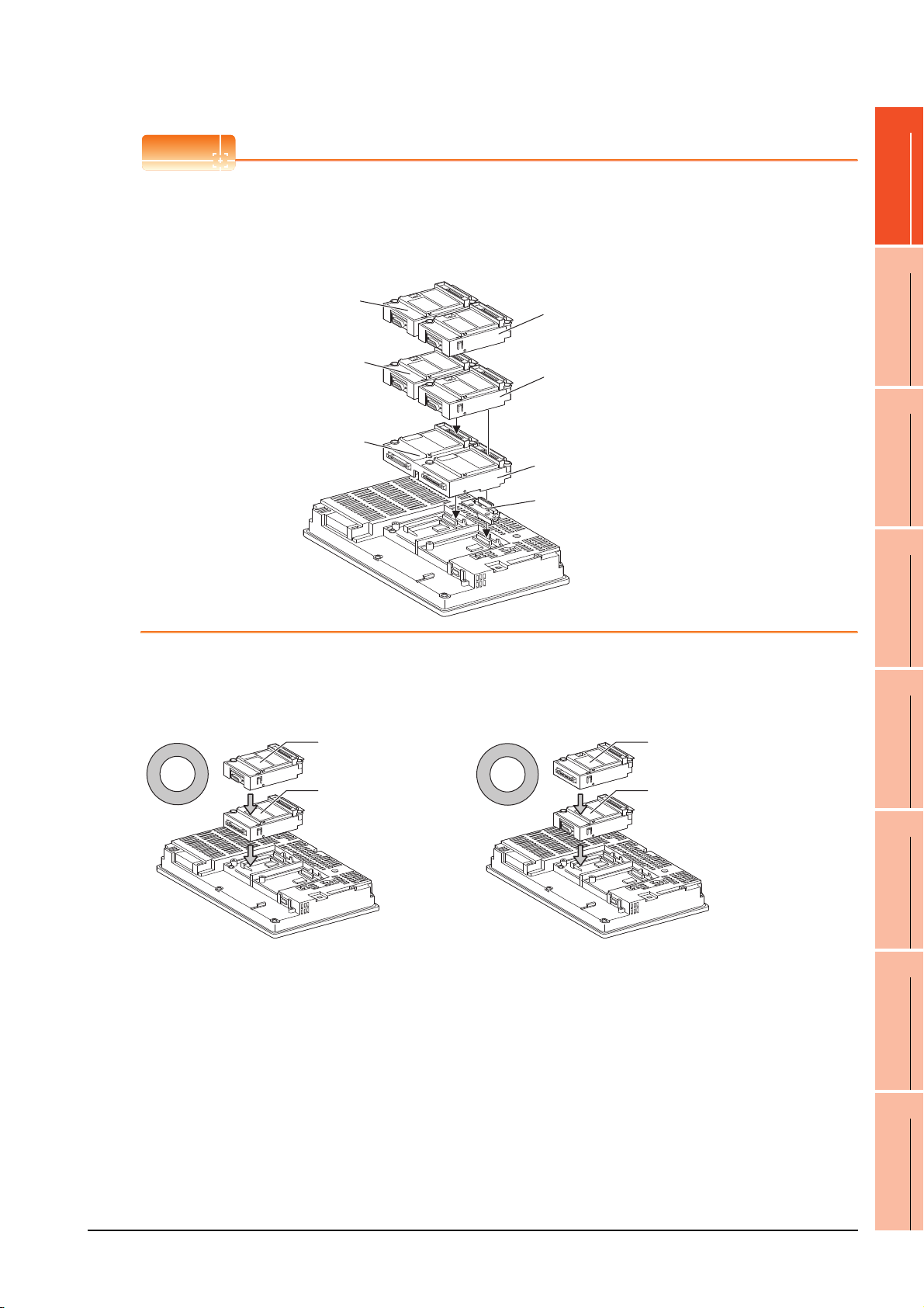
POINTPOINTPOINT
Cautions for using GT15-QBUS2 and GT15-ABUS2
Recognized as the
3rd stage of extend
interface 1
Recognized as the 2nd stage
of extend interface 2
Recognized as the 1st stage
of extend interface 2
Recognized as the
2nd stage of extend
interface 1
Recognized as the 1st stage
of extend interface 1
GT15-QBUS2, GT15-ABUS2
Relay connector
Serial communication unit
Bus connection unit
Bus connection unit
Serial communication unit
The stage number of communication units installed on the next stage of GT15-QBUS2 or GT15-ABUS2 are
recognized by the GOT differently depending on the extension interface position.
For communication units installed in the extension interface 2 side, even if the communication unit is physically
installed in the 2nd stage position, the GOT recognizes the position as the 1st stage.
1
PREPARATORY
PROCEDURES FOR
MONITORING
2
DEVICE RANGE
THAT CAN BE SET
3
ACCESS RANGE
FOR MONITORING
4
(2) Standard size bus connection unit (GT15-QBUS and GT15-ABUS)
A bus connection unit can be installed in any position (1st to 3rd stage) of the extension interface.
Example: Installing a bus connection unit and serial communication units
HOW TO MONITOR
REDUNTANT
SYSTEM
5
BUS CONNECTION
6
DIRECT
CONNECTION TO
CPU
7
COMPUTER LINK
CONNECTION
8
1. PREPARATORY PROCEDURES FOR MONITORING
1.3 Option Devices for the Respective Connection
1 - 21
ETHERNET
CONNECTION
Page 54

When using a MELSECNET/H communication unit, CC-Link IE Controller Network
POINTPOINTPOINT
Serial communication unit
MELSECNET/H
communication unit
MELSECNET/H
communication unit
Serial communication unit
communication unit, CC-Link IE Field Network communication unit, or CC-Link communication
unit (GT15-J61BT13)
Install a MELSECNET/H communication unit, CC-Link IE Controller Network communication unit, CC-Link IE Field
Network communication unit, or CC-Link communication unit in the 1st stage of an extension interface.
These communication units cannot be used if installed in the 2nd or higher stage.
Example: When installing a MELSECNET/H communication unit and a serial communication unit
Precautions for using a MELSECNET/H communication unit, CC-Link IE Controller Network communication unit,
CC-Link IE Field Network communication unit, CC-Link communication unit (GT15-J61BT13)
The installed stage number of communication units installed on the next stage of MELSECNET/H communication
unit, CC-Link IE Controller Network communication unit, CC-Link IE Field Network communication unit, or CC-Link
communication unit are recognized by the GOT differently depending on the extension interface position.
For communication units installed in the extension interface 2 side, even if the communication unit is physically
installed in the 2nd stage position, the GOT recognizes the position as the 1st stage.
Recognized as the 3rd stage
of extension interface 1
Recognized as the 2nd stage
of extension interface 1
Recognized as the 1st stage
of extension interface 1
Recognized as the 2nd stage
of extension interface 2
Recognized as the 1st stage
of extension interface 2
MELSECNET/H communication unit
Relay connector
1 - 22
1. PREPARATORY PROCEDURES FOR MONITORING
1.3 Option Devices for the Respective Connection
Page 55
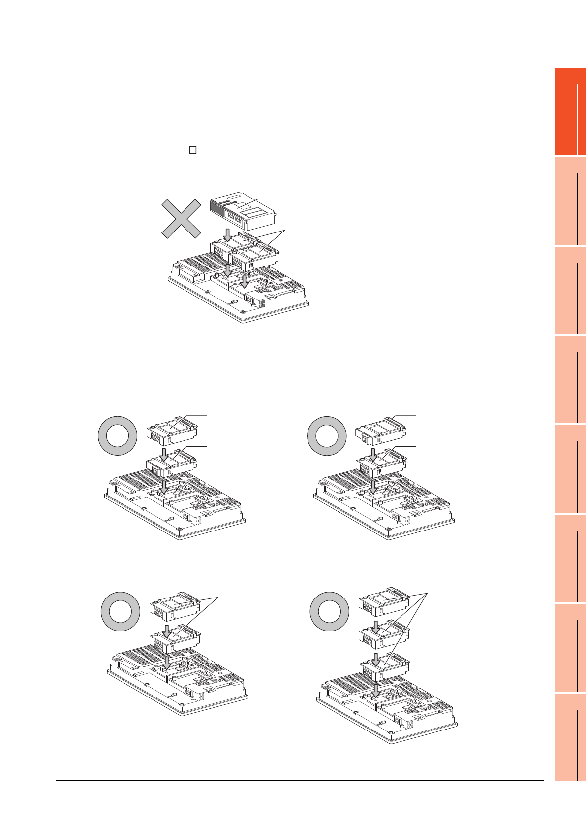
When using a MELSECNET/10 communication unit (GT15-75J71LP23-Z, GT15- 75J71BR13-
Serial communication unit
Ethernet
communication unit
Ethernet
communication unit
Serial communication unit
Serial
communication
unit
Serial
communication
unit
Z) or CC-Link communication unit (GT15-75J61BT13-Z)
Install a MELSECNET/10 communication unit (GT15-75J71LP23-Z, GT15-75J71BR13-Z) or CC-Link communication
unit (GT15-75J61BT13-Z) at the 1st stage of the extension interface.
These communication units cannot be used if installed in the 2nd or higher stage.
For GT16 and the GT155 , the MELSECNET/10 communication unit (GT15-75J71LP23-Z, GT15- 75J71BR13-Z)
and the CC-Link communication unit (GT15-75J61BT13-Z) are not applicable.
Example: When installing a MELSECNET/10 communication unit and a serial communication unit
MELSECNET/10
communication unit
1
PREPARATORY
PROCEDURES FOR
MONITORING
2
Serial communication unit
When using an Ethernet communication unit
An Ethernet communication unit can be installed in any position (1st to 3rd stage) of the extension interface.
For GT16, the Ethernet communication unit is not applicable.
Use the Ethernet interface built in the GOT.
Example: When installing an Ethernet communication unit and a serial communication unit
DEVICE RANGE
THAT CAN BE SET
3
ACCESS RANGE
FOR MONITORING
4
HOW TO MONITOR
REDUNTANT
SYSTEM
5
BUS CONNECTION
6
When using a serial communication unit
A serial communication unit can be installed in any position (1st to 3rd stage) of the extension interface.
1. PREPARATORY PROCEDURES FOR MONITORING
1.3 Option Devices for the Respective Connection
1 - 23
DIRECT
CONNECTION TO
CPU
7
COMPUTER LINK
CONNECTION
8
ETHERNET
CONNECTION
Page 56

When using the printer unit, sound output unit, or external I/O unit
Printer unit
Communication
unit
Printer unit
Communication
unit
MELSECNET/H
communication unit
Video/RGB
input unit
Video/RGB
input unit
MELSECNET/H
communication unit
The printer unit, sound output unit, or external I/O unit can be installed in any position (1st to 3rd stage) of the
extension interface.
Example: When installing a printer unit
When using the video input unit, RGB input unit, video/RGB input unit, RGB output unit, or
multimedia unit
Install the video input unit, RGB input unit, video/RGB input unit, RGB output unit, or multimedia unit at the 1st stage
of the extension interface.These units cannot be used if installed in the 2nd or higher stage.
When any of these units is used, the communication units indicated below must be installed in the 2nd stage of the
extension interface.
Communication unit Model
Bus connection unit GT15-QBUS2, GT15-ABUS2
MELSECNET/H communication unit GT15-J71LP23-25, GT15-J71BR13
CC-Link IE Controller Network
communication unit
CC-Link communication unit GT15-J61BT13
GT15-J71GP23-SX
Example: When installing a video input unit and a MELSECNET/H communication unit
1 - 24
1. PREPARATORY PROCEDURES FOR MONITORING
1.3 Option Devices for the Respective Connection
Page 57

POINTPOINTPOINT
Precautions for video input unit, RGB input unit, video/RGB input unit, RGB output unit, and multimedia unit
Serial communication
unit
CF card unit
CF card unit
Serial communication
unit
When a communication unit is installed on any of the units above, the stage number of the communication unit
recognized by the GOT varies according to the extension interface.
For communication units installed in the extension interface 2 side, even if the communication unit is physically
installed in the 2nd stage position, the GOT recognizes the position as the 1st stage.
Recognized as the 3rd stage of
extension interface 1
Recognized as the 2nd stage of
extension interface 1
Recognized as the 1st stage of
extension interface 1
Recognized as the 2nd stage
of extension interface 2
Recognized as the 1st stage
of extension interface 2
Video/RGB input unit
Relay connector
1
PREPARATORY
PROCEDURES FOR
MONITORING
2
DEVICE RANGE
THAT CAN BE SET
3
ACCESS RANGE
FOR MONITORING
4
When using CF card unit or CF card extension unit
Install the CF card unit or CF card extension unit on the extension interface at the last.
The following figures show how to install the CF card unit.
HOW TO MONITOR
REDUNTANT
SYSTEM
5
BUS CONNECTION
6
DIRECT
CONNECTION TO
CPU
7
COMPUTER LINK
CONNECTION
8
1. PREPARATORY PROCEDURES FOR MONITORING
1.3 Option Devices for the Respective Connection
1 - 25
ETHERNET
CONNECTION
Page 58
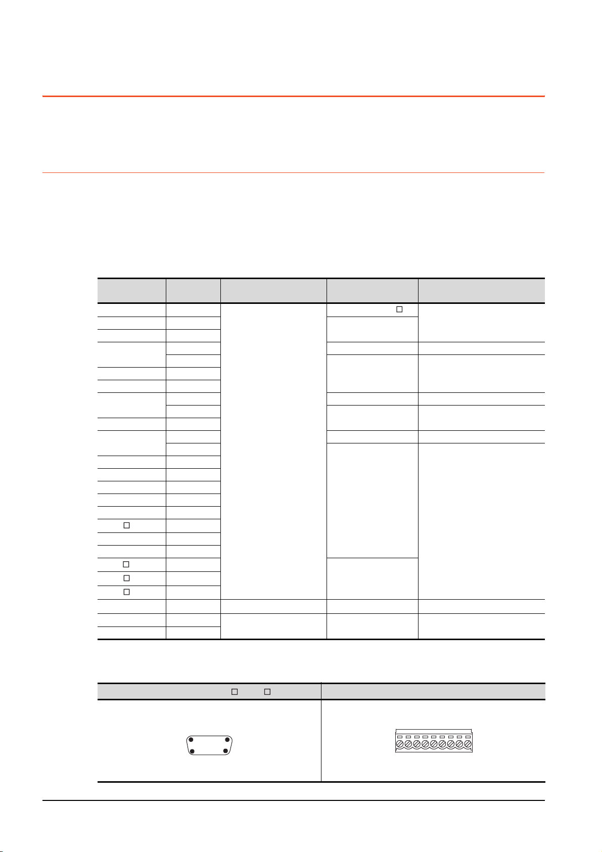
1.4 Connection Cables for the Respective Connection
r
See from the back of a
GOT main part
9-pin terminal block
SD
RD
ER
DR
SG
CSRSNC
NC
To connect the GOT to a device in the respective connection type, connection cables between the GOT and a device are
necessary.
For cables needed for each connection, refer to each chapter for connection.
1.4.1 GOT connector specifications
The following shows the connector specifications on the GOT side.
Refer to the following table when preparing connection cables by the user.
RS-232 interface
Use the following as the RS-232 interface and RS-232 communication unit connector on the GOT. For the GOT side
connection cable, use a connector and connector cover applicable to the GOT connector.
(1) Connector specifications
GOT
GT16 ―
GT1595-X ―
GT1585V-S ―
GT1585-STBA
GT1575V-S ―
GT1575-STBA
GT1575-STBD ―
GT1575-VTBA
GT1575-VTBD ―
GT1575-VN ―
GT1572-VN ―
GT1565-V ―
GT1562-VN ―
GT155
GT14 ―
GT12 ―
GT115 -Q
GT105 -Q
GT104 -Q
GT1030, GT1020
GT15-RS2-9P ―
GT01-RS4-M ―
*1 For the procedure to check the GT15 hardware version, refer to the GT15 User's Manual.
*2 The terminal block (MC1.5/9-ST-3.5 or corresponding product) of the cable side is packed together with the GT1030, GT1020.
(2) Connector pin arrangement
GT16, GT15, GT14, GT12, GT11, GT105 , GT104 , GT01-RS4-M
Hardware
*1
version
B or later GM-C9RMDU11 Honda Tsushin Kogyo Co., Ltd.
C
B or later GM-C9RMDU11 Honda Tsushin Kogyo Co., Ltd.
C
D or later GM-C9RMDU11 Honda Tsushin Kogyo Co., Ltd.
E
―
―
―
―
―
Connector type Connector model Manufacturer
17LE-23090-27(D4C )
DDK Ltd.
DDK Ltd.
GT1030, GT1020
9-pin D-sub (male)
inch screw fixed type
9-pin terminal block
9-pin D-sub (male)
inch screw fixed type
17LE-23090-27(D4CK)
17LE-23090-27(D4CK) DDK Ltd.GT1585-STBD ―
17LE-23090-27(D4CK) DDK Ltd.
17LE-23090-27(D4CK)
17LE-23090-27(D3CC)
*2
MC1.5/9-G-3.5BK PHOENIX CONTACT Inc
17LE-23090-27(D3CC) DDK Ltd.
1 - 26
GOT main part connecto
see from the front
15
69
9-pin D-sub (male)
1. PREPARATORY PROCEDURES FOR MONITORING
1.4 Connection Cables for the Respective Connection
Page 59
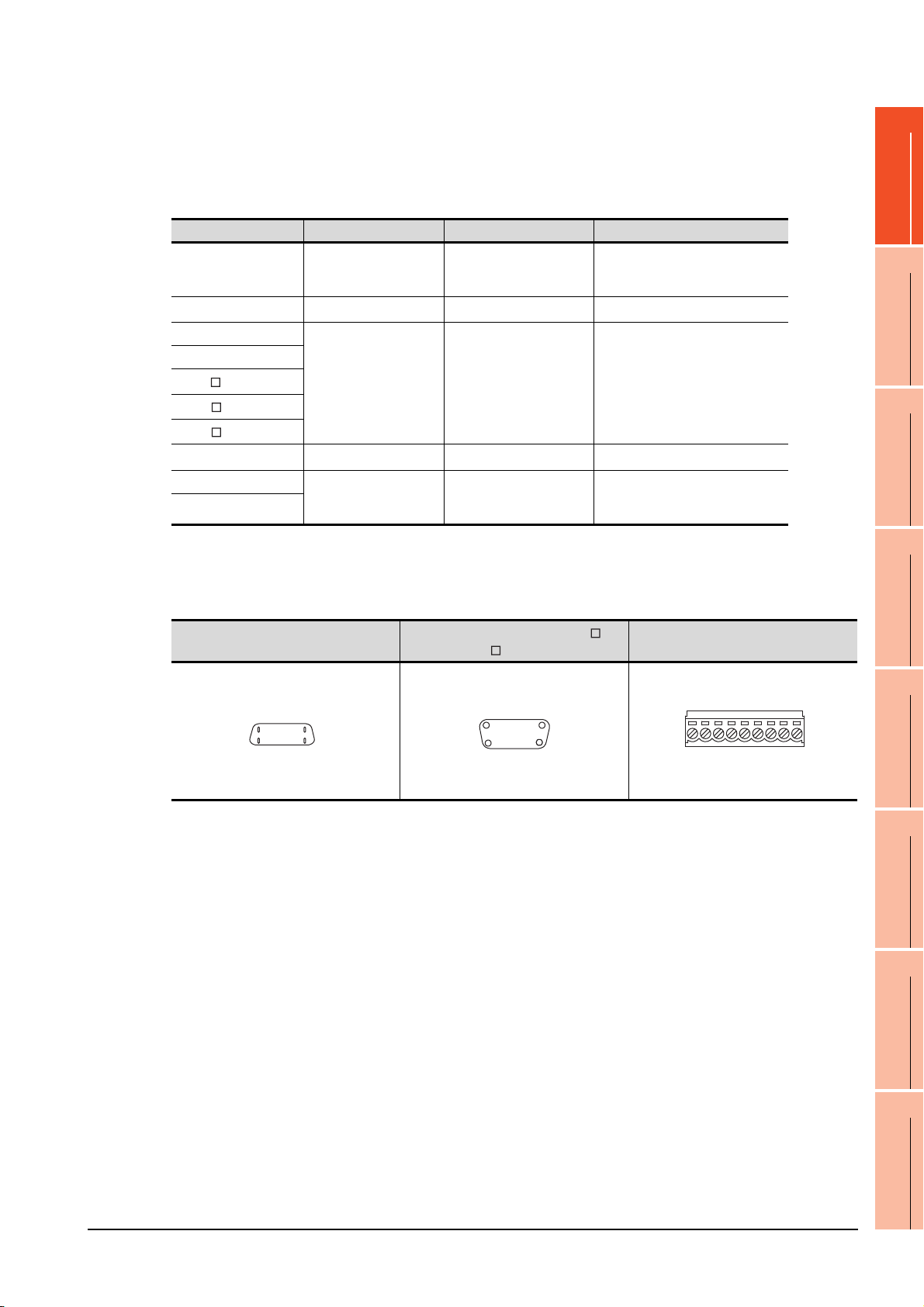
RS-422 interface
14-pin (female)
GOT main part connector
see from the front
814
17
9-pin D-sub (female)
GOT main part connector
see from the front
51
96
See from the back of a
GOT main part
9-pin terminal block
SDA
SDB
RDA
RDB
SG
RSB
RSA
CSA
CSB
Use the following as the RS-422 interface and the RS-422/485 communication unit connector on the GOT.
For the GOT side of the connection cable, use a connector and connector cover applicable to the GOT connector.
(1) Connector model
GOT Connector type Connector model Manufacturer
9-pin D-sub (female)
RS-422 conversion unit
*1
GT16
GT14
GT12
GT115 -Q
GT105 -Q
GT104 -Q
GT1030, GT1020
GT15-RS4-9S 9-pin D-sub (female)
GT01-RS4-M
*1 When connecting to the RS-422/485 interface, use HDR-E14MAG1+ as a cable connector.
To use HDR-E14MAG1+, a dedicated pressure welding tool is required.
For details on the connector and pressure welding tool, contact Honda Tsushin Kogyo Co., Ltd.
*2 The terminal block (MC1.5/9-ST-3.5 or corresponding product) of the cable side is packed together with the GT1030, GT1020.
(2) Connector pin arrangement
M2.6 millimeter screw
fixed type
14-pin (female) HDR-EC14LFDT1-SLE+ Honda Tsushin Kogyo Co., Ltd.
9-pin D-sub (female)
M2.6 millimeter screw
fixed type
9-pin terminal block
M2.6 millimeter screw
fixed type
*2
17LE-13090-27(D2AC) DDK Ltd.
17LE-13090-27(D3AC) DDK Ltd.
MC1.5/9-G-3.5BK PHOENIX CONTACT Inc.
17LE-13090-27(D3AC) DDK Ltd.
1
PREPARATORY
PROCEDURES FOR
MONITORING
2
DEVICE RANGE
THAT CAN BE SET
3
ACCESS RANGE
FOR MONITORING
4
GT16
GT15, GT14, GT12, GT11, GT105 ,
GT104 , GT01-RS4-M
GT1030, GT1020
HOW TO MONITOR
REDUNTANT
SYSTEM
5
BUS CONNECTION
6
DIRECT
CONNECTION TO
CPU
7
COMPUTER LINK
CONNECTION
8
1. PREPARATORY PROCEDURES FOR MONITORING
1.4 Connection Cables for the Respective Connection
1 - 27
ETHERNET
CONNECTION
Page 60

RS-485 interface
14-pin (female)
GOT main part connector
see from the front
814
17
9-pin D-sub (female)
GOT main part connector
see from the front
51
96
Use the following as the RS-485 interface and the RS-422/485 communication unit connector on the GOT.
For the GOT side of the connection cable, use a connector and connector cover applicable to the GOT connector.
(1) Connector model
GOT
*2
GT16
GT14 ―
GT12 ―
GT1155-QTBD C or later
GT1155-QSBD
GT1150-QLBD
GT105 -Q
GT104 -Q
GT1030 B or later
GT1020 E or later
GT15-RS4-9S ―
GT15-RS4-TE ――SL-SMT3.5/10/90F BOX Weidmuller interconnections inc
*1 For the checking procedure of the hardware version, refer to the User's Manual.
*2 When connecting to the RS-422/485 interface, use HDR-E14MAG1+ as a cable connector.
*3 The terminal block (MC1.5/9-ST-3.5 or corresponding product) of the cable side is packed together with the GT1030, GT1020.
Hardware version
F or later
C or later
A or later
To use HDR-E14MAG1+, a dedicated pressure welding tool is required.
For details on the connector and pressure welding tool, contact Honda Tsushin Kogyo Co., Ltd..
(2) Connector pin arrangement
GT16
*1
― 14-pin (female) HDR-EC14LFDT1-SLE+ Honda Tsushin Kogyo Co., Ltd.
Connector type Connector model Manufacturer
9-pin D-sub (female)
M2.6 millimeter screw
fixed type
9-pin terminal block
9-pin D-sub (female)
M2.6 millimeter screw
fixed type
GT15, GT14, GT12, GT11,
GT105 , GT104
17LE-13090-27(D3AC) DDK Ltd.
*3
MC1.5/9-G-3.5BK PHOENIX CONTACT Inc
17LE-13090-27(D3AC) DDK Ltd.
GT1030, GT1020
See from the back of a
GOT main part
CSB
SG
SDA
SDB
RDA
RDB
RSB
RSA
CSA
9-pin terminal block
1 - 28
1. PREPARATORY PROCEDURES FOR MONITORING
1.4 Connection Cables for the Respective Connection
Page 61

1.4.2 Coaxial cable connector connection method
Cable in use
A
3C-2V 15mm
5C-2V, 5C-2V-CCY 10mm
Clamp
Gasket
Washer
Nut
Cable in use
B C
3C-2V 6mm 3mm
5C-2V, 5C-2V-CCY 7mm 5mm
The following describes the method for connecting the BNC connector (connector plug for coaxial cable) and the cable.
CAUTION
Solder the coaxial cable connectors properly.
Insufficient soldering may result in malfunctions.
1
PREPARATORY
PROCEDURES FOR
MONITORING
2
Components of the BNC connector
Nut Washer Gasket
Plug shell
Clamp Contact
A
Cut this portion of the outer sheath
Internal conductor
Insulating material
C
B
Clamp and external
conductor
Structure of the coaxial cable
External conductor
Outer sheath
Insulating material
Internal conductor
1. Remove the external sheath of the coaxial cable with
dimensions as shown below.
2. Pass the nut, washer, gasket, and clamp through the coaxial
cable as shown on the left and loosen the external conductor.
3. Cut the external conductor, insulting material, and internal
conductor with the dimensions as shown below.
Note that the external conductor should be cut to the same
dimension as the tapered section of the clamp and smoothed
down to the clamp.
DEVICE RANGE
THAT CAN BE SET
3
ACCESS RANGE
FOR MONITORING
4
HOW TO MONITOR
REDUNTANT
SYSTEM
5
BUS CONNECTION
6
Solder here
Precautions for soldering
Note the following precautions when soldering the internal conductor and contact.
• Make sure that the solder does not bead up at the soldered section.
• Make sure there are no gaps between the connector and cable insulator or they do not cut into each other.
• Perform soldering quickly so the insulation material does not become deformed.
4. Solder the contact to the internal conductor.
5. Insert the connector assembly shown in into the plug
shell and screw the nut into the plug shell.
1. PREPARATORY PROCEDURES FOR MONITORING
1.4 Connection Cables for the Respective Connection
1 - 29
DIRECT
CONNECTION TO
CPU
7
COMPUTER LINK
CONNECTION
8
ETHERNET
CONNECTION
Page 62
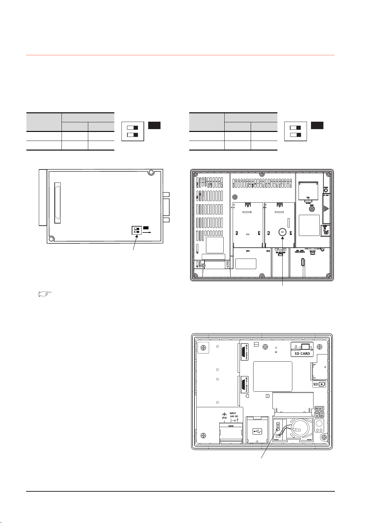
1.4.3 Terminating resistors of GOT
SW1
ON
12
ON
SW1
ON
12
Rear view of RS-422/485 communication unit.
Terminating resistor setting switch
Terminating resistor selector switch
The following shows the terminating resistor specifications on the GOT side.
When setting the terminating resistor in each connection type, refer to the following.
RS-422/485 communication unit
Set the terminating resistor using the terminating
resistor setting switch.
Terminating
*1
resistor
100 OHM ON ON
Disable OFF OFF
*1 The default setting is "Disable".
• For RS-422/485 communication unit
Switch No.
1 2
GT16
Set the terminating resistor using the terminating
resistor setting switch.
Terminating
*1
resistor
Enable ON ON
Disable OFF OFF
*1 The default setting is "Disable".
• For GT1685M-S
Switch No.
1 2
12
ON
SW1
RS-232/485 signal conversion adapter
For details, refer to the following.
1.4.4 Setting the RS-232/485 signal conversion
adaptor
Terminating resistor setting switch
(inside the cover)
GT14
Set the terminating resistor using the terminating
resistor setting switch.
1 - 30
1. PREPARATORY PROCEDURES FOR MONITORING
1.4 Connection Cables for the Respective Connection
Page 63
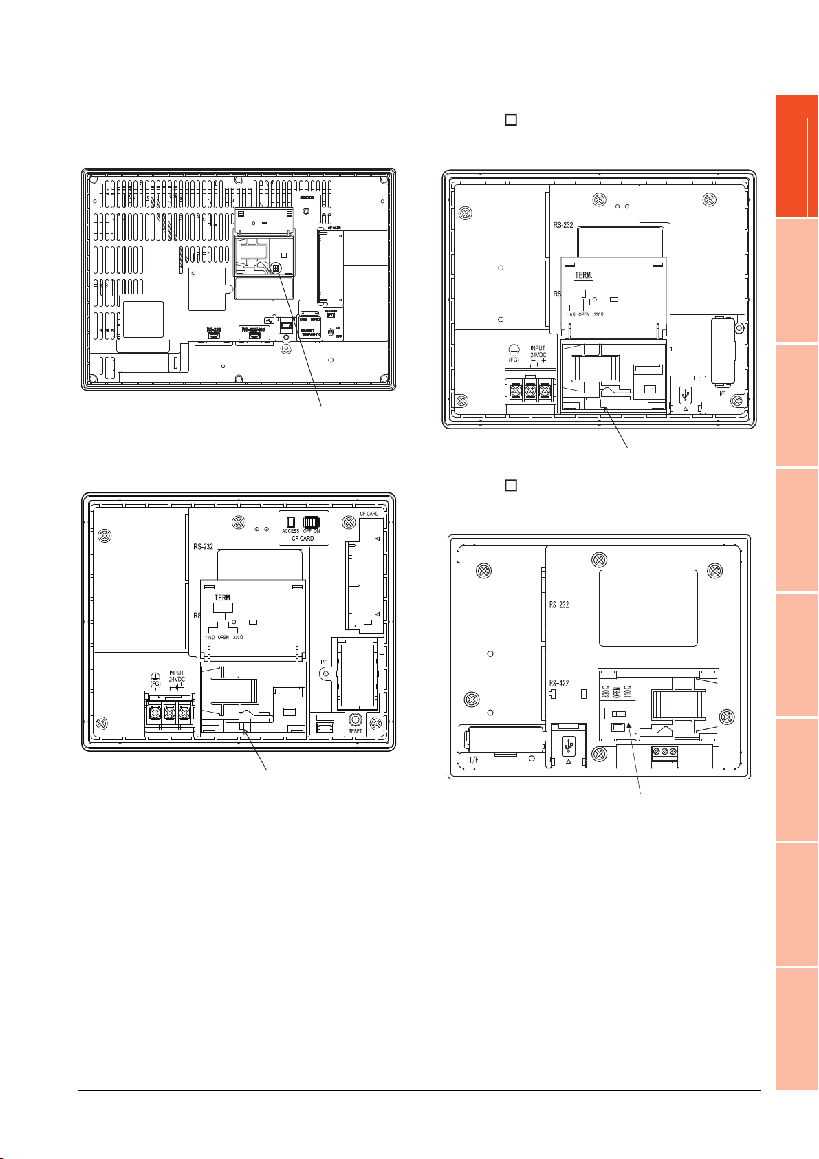
GT12
Terminating resistor selector switch
Terminating resistor selector switch
Set the terminating resistor using the terminating
resistor setting switch.
Terminating resistor selector switch
GT105
Set the terminating resistor using the terminating
resistor setting switch.
1
PREPARATORY
PROCEDURES FOR
MONITORING
2
DEVICE RANGE
THAT CAN BE SET
3
GT11
Set the terminating resistor using the terminating
resistor setting switch.
Terminating resistor selector switch
GT104
Set the terminating resistor using the terminating
resistor setting switch.
ACCESS RANGE
FOR MONITORING
4
HOW TO MONITOR
REDUNTANT
SYSTEM
5
BUS CONNECTION
6
DIRECT
CONNECTION TO
CPU
7
1. PREPARATORY PROCEDURES FOR MONITORING
1.4 Connection Cables for the Respective Connection
1 - 31
COMPUTER LINK
CONNECTION
8
ETHERNET
CONNECTION
Page 64
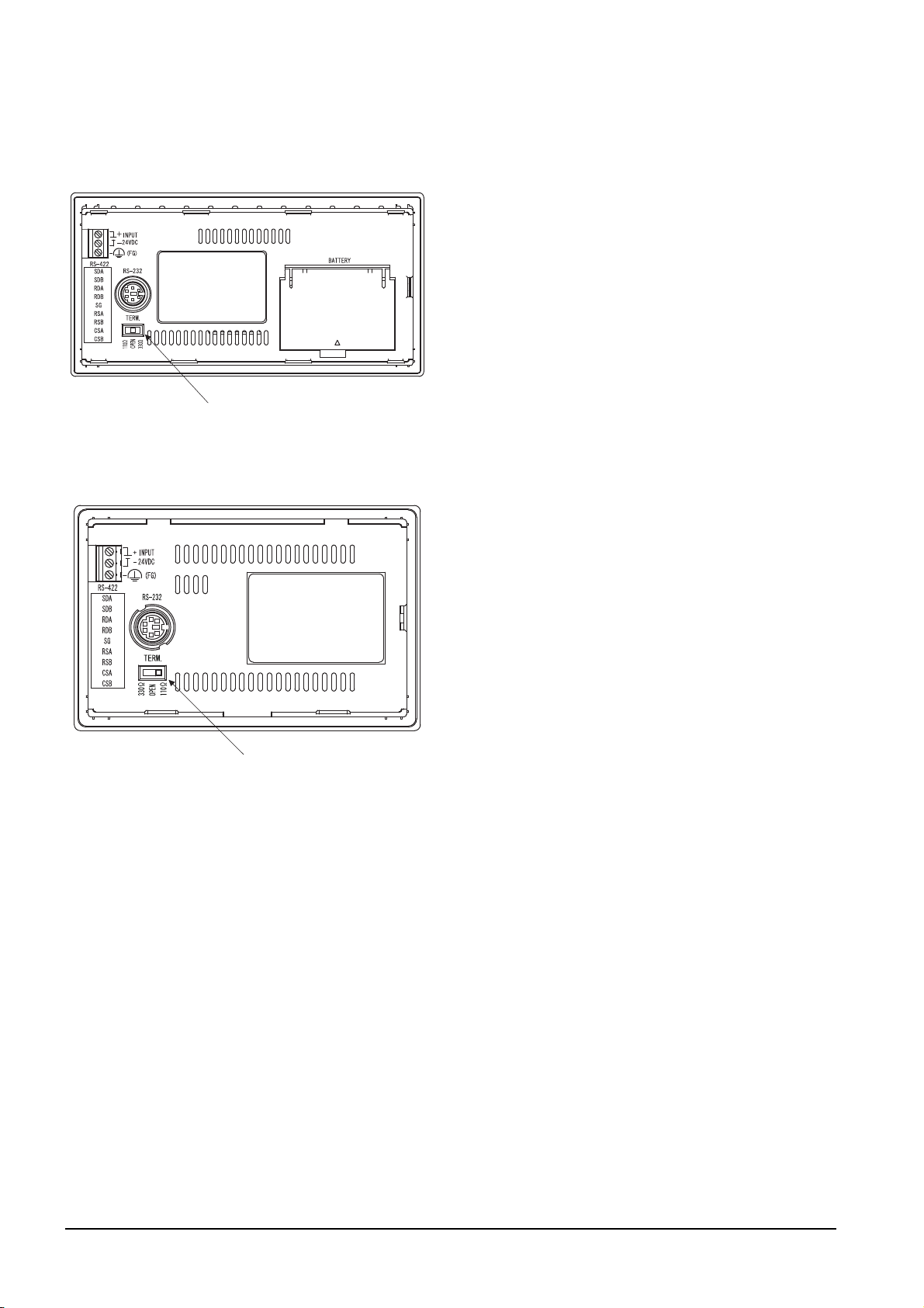
GT1030
Terminating resistor selector switch
Terminating resistor selector switch
Set the terminating resistor using the terminating
resistor setting switch.
GT1020
Set the terminating resistor using the terminating
resistor setting switch.
1 - 32
1. PREPARATORY PROCEDURES FOR MONITORING
1.4 Connection Cables for the Respective Connection
Page 65

1.4.4 Setting the RS-232/485 signal conversion adaptor
POINTPOINTPOINT
POINTPOINTPOINT
2-wire/4-wire terminating resistor setting switch
Set the 2-wire/4-wire terminating resistor setting switch according to the connection type.
Enable the 5V power supply
Make sure to validate "Enable the 5V power supply" in the [RS232 Setting] to operate the RS-232/485 signal
conversion adaptor.
1.1.2 I/F communication setting
When validating the function using the utility function of the GOT main unit, refer to the following manual.
GT14 User's Manual 8.2 Utility Function List
1
PREPARATORY
PROCEDURES FOR
MONITORING
2
DEVICE RANGE
THAT CAN BE SET
3
ACCESS RANGE
FOR MONITORING
4
Setting the 2-wire/4-wire terminating resistor setting switch
1O2N345
Setting item Set value
2-wire/4-wire
Terminating resistor
RS-232/485 signal conversion adapter
For details on the RS-232/485 signal conversion adapter, refer to the following manual.
2-wire (1Pair) ON ON - - - OFF
4-wire (2Pair) OFF OFF - - - OFF
110
OPEN - - OFF OFF OFF OFF
330
GT14-RS2T4-9P RS-232/485 Signal Conversion Adapter User's Manual
1 2 3 4 5 6
--ONOFFOFFOFF
--OFFONONOFF
6
Switch No.
HOW TO MONITOR
REDUNTANT
SYSTEM
5
BUS CONNECTION
6
DIRECT
CONNECTION TO
CPU
7
COMPUTER LINK
CONNECTION
8
1. PREPARATORY PROCEDURES FOR MONITORING
1.4 Connection Cables for the Respective Connection
1 - 33
ETHERNET
CONNECTION
Page 66
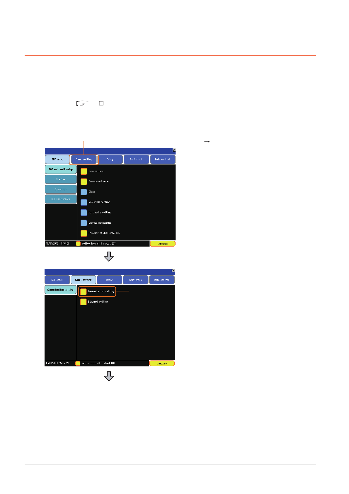
1.5 Verifying GOT Recognizes Connected Equipment
1.
2.
Verify the GOT recognizes controllers on [Communication Settings] of the Utility.
• Channel number of communication interface, communication drivers allocation status
• Communication unit installation status
For details on the Utility, refer to the following manual.
GT User's Manual
When using GT16, GT12
(For GT16)
1. After powering up the GOT, touch [Main menu]
[Communication setting] from the Utility.
2. Touch [Communication setting].
1 - 34
1. PREPARATORY PROCEDURES FOR MONITORING
1.5 Verifying GOT Recognizes Connected Equipment
Page 67
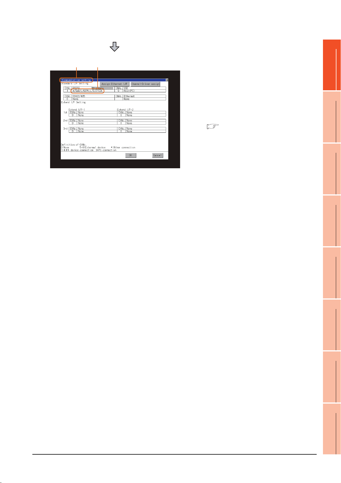
1
3. 4.
3. The [Communication Settings] appears.
4. Verify that the communication driver name to
be used is displayed in the communication
interface box to be used.
5. When the communication driver name is not
displayed normally, carry out the following
procedure again.
1.1Setting the Communication Interface
PREPARATORY
PROCEDURES FOR
MONITORING
2
DEVICE RANGE
THAT CAN BE SET
3
ACCESS RANGE
FOR MONITORING
4
HOW TO MONITOR
REDUNTANT
SYSTEM
5
BUS CONNECTION
6
DIRECT
CONNECTION TO
CPU
7
COMPUTER LINK
CONNECTION
8
1. PREPARATORY PROCEDURES FOR MONITORING
1.5 Verifying GOT Recognizes Connected Equipment
1 - 35
ETHERNET
CONNECTION
Page 68

For GT15, GT14 or GT11
1.
2.
3. 4.
1. After powering up the GOT, touch [Main Menu]
[Communication setting] from the Utility.
2. Touch [Communication setting].
(The screen on the left is not displayed on
GT11.)
1 - 36
3. The [Communication Setting] appears.
4. Verify that the communication driver name to
be used is displayed in the box for the
communication interface to be used.
5. When the communication driver name is not
displayed normally, carry out the following
procedure again.
1.1Setting the Communication Interface
1. PREPARATORY PROCEDURES FOR MONITORING
1.5 Verifying GOT Recognizes Connected Equipment
Page 69

For GT10
1.
2.
3. 4.
1. After powering up the GOT, touch [Main Menu]
[Comm. Setting] from the Utility.
1
PREPARATORY
PROCEDURES FOR
MONITORING
2
2. Touch [Standard I/F] on [Comm. Setting].
3. The [Standard I/F] appears.
4. Verify that the communication driver name to
be used is displayed in the box for the
communication interface to be used.
5. When the communication driver name is not
displayed normally, carry out the following
procedure again.
1.1Setting the Communication Interface
DEVICE RANGE
THAT CAN BE SET
3
ACCESS RANGE
FOR MONITORING
4
HOW TO MONITOR
REDUNTANT
SYSTEM
5
BUS CONNECTION
6
1. PREPARATORY PROCEDURES FOR MONITORING
1.5 Verifying GOT Recognizes Connected Equipment
1 - 37
DIRECT
CONNECTION TO
CPU
7
COMPUTER LINK
CONNECTION
8
ETHERNET
CONNECTION
Page 70

POINTPOINTPOINT
Utility
(1) How to display Utility (at default)
When using GT16, GT1595, GT14, GT12 or GT1020
Utility call key
1-point press on GOT screen upper-left corner
Utility display
(When using GT15)(When using GT16, GT12)
When using GT1585, GT157 ,
(When using GT14, GT11)
GT104 )
GT156 , GT155 , GT11, GT105 ,
GT104 or GT1030
(When using GT105 ,
Utility call key
Simultaneous 2-point press
(When using GT1030,GT1020)
(2) Utility call
When setting [Pressing time] to other than 0 second on the setting screen of the utility call key, press and hold
the utility call key until the buzzer sounds.For the setting of the utility call key, refer to the following.
GT User's Manual
(3) Communication interface setting by the Utility
The communication interface setting can be changed on the Utility's [Communication setting] after writing
[Communication Settings] of project data.
For details on the Utility, refer to the following manual.
GT User's Manual
(4) Precedence in communication settings
When settings are made by GT Designer3 or the Utility, the latest setting is effective.
1 - 38
1. PREPARATORY PROCEDURES FOR MONITORING
1.5 Verifying GOT Recognizes Connected Equipment
Page 71

1.6 Checking for Normal Monitoring
HINTHINTHINT
Error code Communication Channel No.
Error message Time of occurrence
(Displayed only for errors)
1.6.1 Check on the GOT
1
Check for errors occurring on the GOT
Presetting the system alarm to project data allows you to identify errors occurred on the GOT, PLC CPU, servo
amplifier and communications.
For details on the operation method of the GOT Utility screen, refer to the following manual.
GT User's Manual
(When using GT15)
PREPARATORY
PROCEDURES FOR
MONITORING
2
DEVICE RANGE
THAT CAN BE SET
3
ACCESS RANGE
FOR MONITORING
4
HOW TO MONITOR
REDUNTANT
SYSTEM
5
Advanced alarm popup display
With the advanced alarm popup display function, alarms are displayed as a popup display regardless of whether
an alarm display object is placed on the screen or not (regardless of the display screen).
Since comments can be flown from right to left, even a long comment can be displayed all.
For details of the advanced popup display, refer to the following manual.
GT Designer3 Screen Design Manual
1. PREPARATORY PROCEDURES FOR MONITORING
1.6 Checking for Normal Monitoring
1 - 39
BUS CONNECTION
6
DIRECT
CONNECTION TO
CPU
7
COMPUTER LINK
CONNECTION
8
ETHERNET
CONNECTION
Page 72

Perform an I/O check
1.
Whether the PLC can communicate with the GOT or not can be checked by the I/O check function.
If this check ends successfully, it means correct communication interface settings and proper cable connection.
Display the I/O check screen by Main Menu.
• For GT16, GT12
Display the I/O check screen by [Main menu] [Self check] [I/O check].
• For GT15, GT14, GT11
Display the I/O check screen by [Main menu] [Debug & self check] [Self check] [I/O check].
For details on the I/O check, refer to the following manual:
GT User's Manual
1.
Touch [CPU] on the I/O check screen.
Touching [
check with the connected PLC.
CPU
] executes the communication
1 - 40
2. When the communication screen ends
successfully, the screen on the left is displayed.
1. PREPARATORY PROCEDURES FOR MONITORING
1.6 Checking for Normal Monitoring
Page 73

Communication monitoring function
Main Menu
Touch [Comm. Setting]
Touch [ ]
Communication settings
Touch [Comm. Monitor]
The communication monitoring is a function that checks whether the PLC can communicate with the GOT.
If this check ends successfully, it means correct communication interface settings and proper cable connection.
Display the communication monitoring function screen by [Main Menu] [Comm. Setting] [Comm. Monitor].
For details on the communication monitoring function, refer to the following manual:
GT10 User's Manual
(Operation of communication monitoring function screen)
1
PREPARATORY
PROCEDURES FOR
MONITORING
2
DEVICE RANGE
THAT CAN BE SET
3
ACCESS RANGE
FOR MONITORING
4
HOW TO MONITOR
REDUNTANT
SYSTEM
5
BUS CONNECTION
6
DIRECT
CONNECTION TO
CPU
7
COMPUTER LINK
CONNECTION
8
1. PREPARATORY PROCEDURES FOR MONITORING
1.6 Checking for Normal Monitoring
1 - 41
ETHERNET
CONNECTION
Page 74
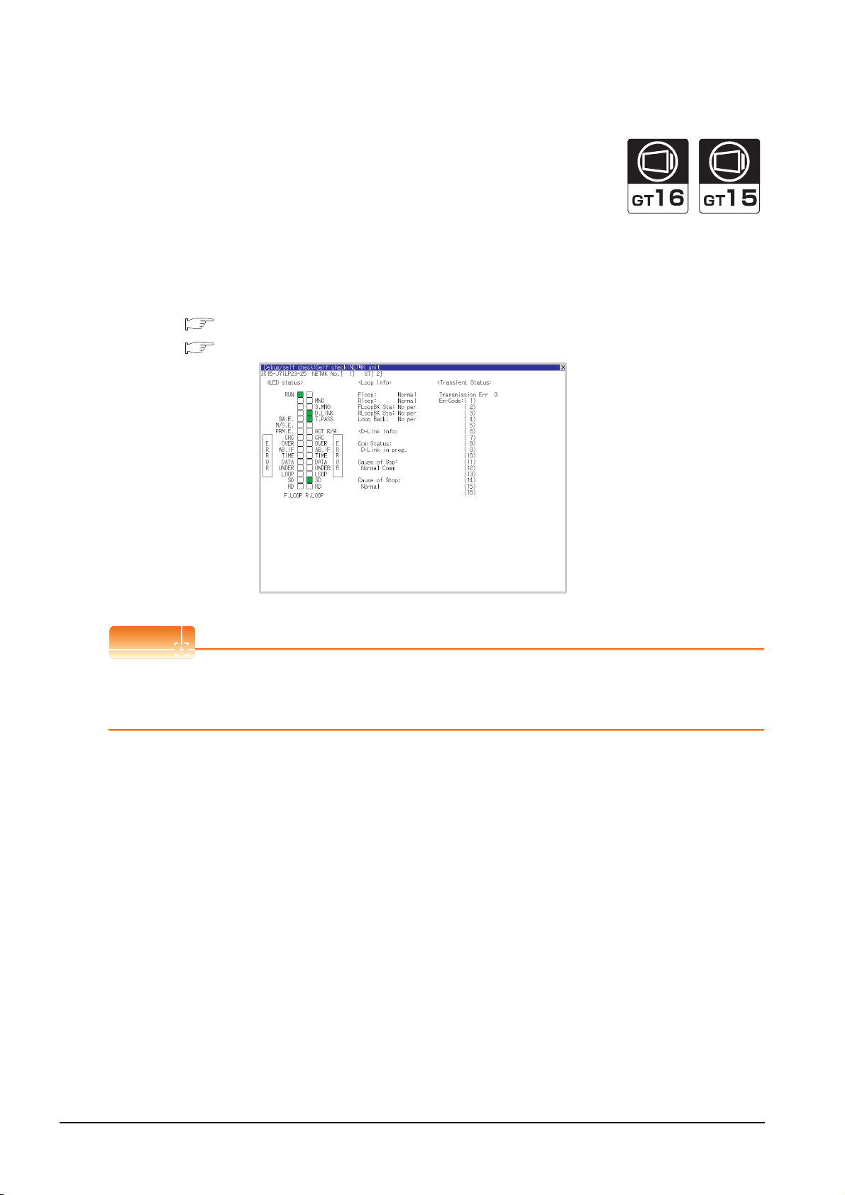
Confirming the communication status with network unit by GOT
POINTPOINTPOINT
(1) For MELSECNET/H, MELSECNET/10 network system
The communication status between the GOT and the MELSECNET/H, MELSECNET/10 network system can be
confirmed by the Utility screen of the GOT.
For details on the operation method of the GOT Utility screen, refer to the following manual.
GT16 User's Manual (Basic Utility)
GT15 User's Manual
Communication unit for displaying network module status
Use the GT15-J71LP23-25 or GT15-J71BR13 for displaying the network module status on the GOT.
The GOT cannot display the network module status with GT15-75J71LP23-Z or GT15-75J71BR13-Z.
1 - 42
1. PREPARATORY PROCEDURES FOR MONITORING
1.6 Checking for Normal Monitoring
Page 75
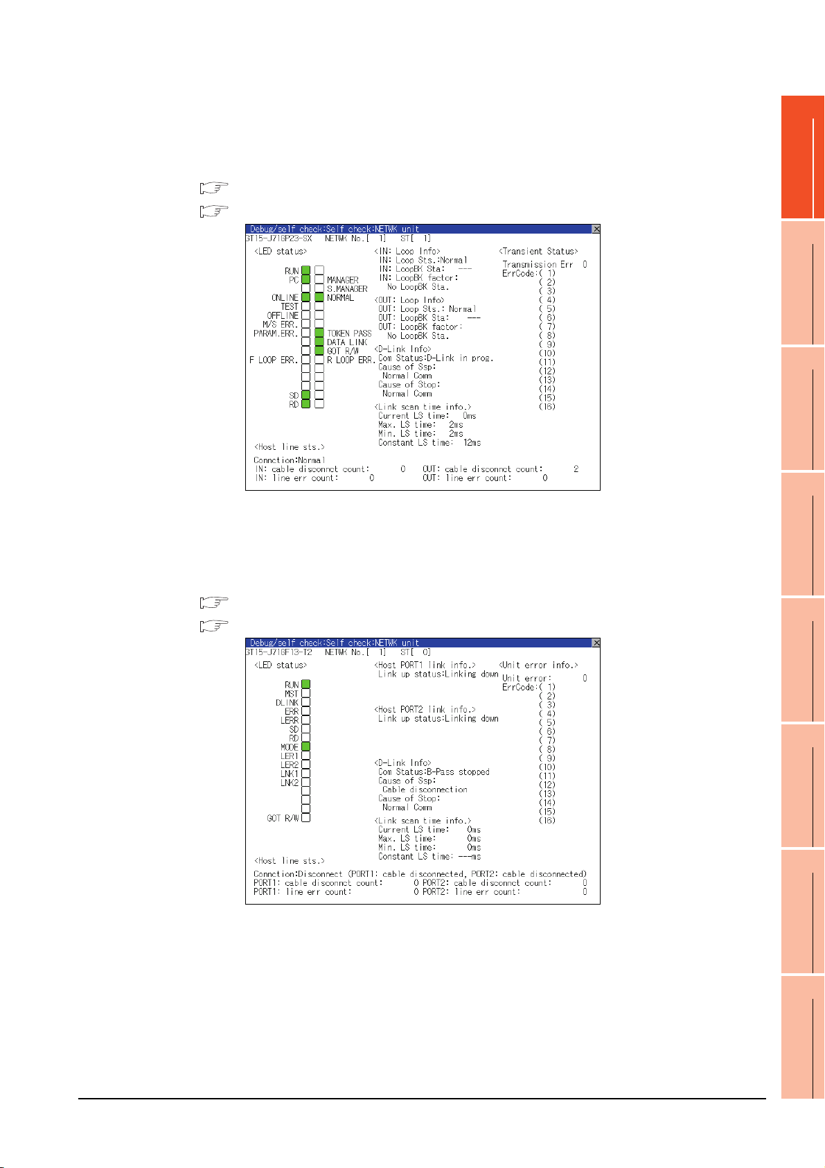
(2) For CC-Link IE Controller Network system
The communication status between the GOT and CC-Link IE Controller Network can be confirmed by the utility
screen of the GOT.
For details on the operation method of the GOT Utility screen, refer to the following manual.
GT16 User's Manual (Basic Utility)
GT15 User's Manual
1
PREPARATORY
PROCEDURES FOR
MONITORING
2
DEVICE RANGE
THAT CAN BE SET
3
ACCESS RANGE
FOR MONITORING
4
(3) For CC-Link IE Field Network system
The communication status between the GOT and CC-Link IE Field Network can be confirmed by the utility
screen of the GOT.
For details on the operation method of the GOT Utility screen, refer to the following manual.
GT16 User's Manual (Basic Utility)
GT15 User's Manual
HOW TO MONITOR
REDUNTANT
SYSTEM
5
BUS CONNECTION
6
DIRECT
CONNECTION TO
CPU
7
1. PREPARATORY PROCEDURES FOR MONITORING
1.6 Checking for Normal Monitoring
1 - 43
COMPUTER LINK
CONNECTION
8
ETHERNET
CONNECTION
Page 76

(4) For CC-Link system
POINTPOINTPOINT
The communication status between the GOT and the CC-Link System can be confirmed by the Utility screen of
the GOT.
For details on the operation method of the GOT Utility screen, refer to the following manual.
GT16 User's Manual (Basic Utility)
GT15 User's Manual
CC-Link communication unit when network module status display is made
When displaying the network module status, use the CC-Link communication unit of MODEL GT15-J61BT13.
For the MODEL GT15-75J61BT13-Z, the network module status cannot be displayed.
1 - 44
1. PREPARATORY PROCEDURES FOR MONITORING
1.6 Checking for Normal Monitoring
Page 77

1.6.2 Confirming the communication state on the GOT side (For Ethernet
POINTPOINTPOINT
2.
1.
Click!
connection)
Confirming the communication state on Windows
(1) When using the Command Prompt of Windows
Execute a Ping command at the Command Prompt of Windows®.
(a) When normal communication
C:\>Ping 192.168.0.18
Reply from 192.168.0.18: bytes=32time<1ms TTL=64
(b) When abnormal communication
C:\>Ping 192.168.0.18
Request timed out.
(2) When using the [PING Test] of GT Designer3
Select [Communication] [Communication configuration] [Ethernet] and [Connection Test] to display
[PING Test].
®
, GT Designer3
®
1. Specify the [GOT IP Address] of the [PING
Test] and click the [PING Test] button.
1
PREPARATORY
PROCEDURES FOR
MONITORING
2
DEVICE RANGE
THAT CAN BE SET
3
ACCESS RANGE
FOR MONITORING
4
2. The [Test Result] is displayed after the [PING
Test] is finished.
(3) When abnormal communication
At abnormal communication, check the followings and execute the Ping command again.
• Mounting condition of Ethernet communication unit
• Cable connecting condition
• Confirmation of [Communication Settings]
• IP address of GOT specified by Ping command
HOW TO MONITOR
REDUNTANT
SYSTEM
5
BUS CONNECTION
6
DIRECT
CONNECTION TO
CPU
7
Ethernet diagnostics of GX Developer
Ethernet diagnostics of GX Developer is available to a Ping test from the PLC.
For details of Ethernet diagnostics of GX Developer, refer to the following manual.
User's manual of the Ethernet module
1. PREPARATORY PROCEDURES FOR MONITORING
1.6 Checking for Normal Monitoring
1 - 45
COMPUTER LINK
CONNECTION
8
ETHERNET
CONNECTION
Page 78

Confirming the communication state on the GOT (For GT16, GT14)
[PING Test] can be confirmed by the Utility screen of the GOT.
For details on the operation method of the GOT Utility screen, refer to the following manual.
GT16 User's Manual (Basic Utility)
GT14 User's Manual
1 - 46
1. PREPARATORY PROCEDURES FOR MONITORING
1.6 Checking for Normal Monitoring
Page 79

1.6.3 Confirming the communication state to each station (Station monitoring
POINTPOINTPOINT
function)
The station monitoring function detects the faults (communication timeout) of the stations monitored by the GOT.
When detecting the abnormal state, it allocates the data for the faulty station to the GOT special register (GS).
(1) No. of faulty stations
(a) Ethernet connection (Except for Ethernet multiple connection)
Total No. of the faulty CPU is stored.
Device b15 to b8 b7 to b0
GS230 (00
(b) Ethernet multiple connection
Total No. of the faulty connected equipment is stored.
Channel Device b15 to b8 b7 to b0
Ch1 GS280 (00
Ch2 GS300 (00
Ch3 GS320 (00
Ch4 GS340 (00
H fixed) No. of faulty stations
H fixed) No. of faulty stations
H fixed) No. of faulty stations
H fixed) No. of faulty stations
H fixed) No. of faulty stations
1
PREPARATORY
PROCEDURES FOR
MONITORING
2
DEVICE RANGE
THAT CAN BE SET
3
ACCESS RANGE
FOR MONITORING
4
When monitoring GS230 on Numerical Display
When monitoring GS230 on Numerical Display, check [mask processing] with data operation tab as the following.
For the data operation, refer to the following manual.
GT Designer3 Screen Design Manual
Numerical Display (Data Operation tab)
Set [mask processing] to the upper eight bits (b8
to b15) of GS230 on Numerical Display.
HOW TO MONITOR
REDUNTANT
SYSTEM
5
BUS CONNECTION
6
DIRECT
CONNECTION TO
CPU
7
COMPUTER LINK
CONNECTION
8
1. PREPARATORY PROCEDURES FOR MONITORING
1.6 Checking for Normal Monitoring
1 - 47
ETHERNET
CONNECTION
Page 80

(2) Faulty station information (GS231 to GS238)
The bit corresponding to the faulty station is set.(0: Normal, 1: Abnormal)
The bit is reset after the fault is recovered.
(a) Ethernet connection (Except for Ethernet multiple connection)
GS231 bit 0
GS231 bit 1
GS231 bit 2
GS231 bit 3
Device
GS231 16151413121110987654321
GS232 32 31 30 29 28 27 26 25 24 23 22 21 20 19 18 17
GS233 48 47 46 45 44 43 42 41 40 39 38 37 36 35 34 33
GS234 64 63 62 61 60 59 58 57 56 55 54 53 52 51 50 49
GS235 80 79 78 77 76 75 74 73 72 71 70 69 68 67 66 65
GS236 96 95 94 93 92 91 90 89 88 87 86 85 84 83 82 81
GS237 112 111 110 109 108 107 106 105 104 103 102 101 100 99 98 97
GS238 128 127 126 125 124 123 122 121 120 119 118 117 116 115 114 113
b15 b14 b13 b12 b11 b10 b9 b8 b7 b6 b5 b4 b3 b2 b1 b0
PLC No.
(b) Ethernet multiple connection, servo amplifier connection, inverter connection
The station number to which each device corresponds changes according to the connection/non
connection with Ethernet.
With Ethernet connection: 1 to 128
With other than Ethernet connection: 0 to 127
Example) With Ethernet connection, when PC No. 100 CPU connecting to Ch3 is faulty, GS327.b3 is set.
The following table shows the case with Ethernet connection.
Device PLC No./Station No.
Ch1 Ch2 Ch3 Ch4 b15 b14 b13 b12 b11 b10 b9 b8 b7 b6 b5 b4 b3 b2 b1 b0
GS281GS301GS321GS34116151413121110987654321
GS282 GS302 GS322 GS342 32 31 30 29 28 27 26 25 24 23 22 21 20 19 18 17
GS283 GS303 GS323 GS343 48 47 46 45 44 43 42 41 40 39 38 37 36 35 34 33
GS284 GS304 GS324 GS344 64 63 62 61 60 59 58 57 56 55 54 53 52 51 50 49
GS285 GS305 GS325 GS345 80 79 78 77 76 75 74 73 72 71 70 69 68 67 66 65
GS286 GS306 GS326 GS346 96 95 94 93 92 91 90 89 88 87 86 85 84 83 82 81
GS287 GS307 GS327 GS347 112 111 110 109 108 107 106 105 104 103 102 101 100 99 98 97
GS288 GS308 GS328 GS348 128 127 126 125 124 123 122 121 120 119 118 117 116 115 114 113
1 - 48
For details on the GS Device, refer to the following manual.
GT Designer3 Screen Design Manual (Fundamentals) Appendix.2.3 GOT special register (GS)
1. PREPARATORY PROCEDURES FOR MONITORING
1.6 Checking for Normal Monitoring
Page 81

(3) Network No., station No. notification
The network No. and station No. of the GOT in Ethernet connection are stored at GOT startup.
If connected by other than Ethernet, 0 is stored.
Device
CH1 CH2 CH3 CH4
GS376 GS378 GS380 GS382 Network No. (1 to 239)
GS377 GS379 GS381 GS383 Station No. (1 to 64)
Description
1
PREPARATORY
PROCEDURES FOR
MONITORING
2
DEVICE RANGE
THAT CAN BE SET
3
ACCESS RANGE
FOR MONITORING
4
HOW TO MONITOR
REDUNTANT
SYSTEM
5
BUS CONNECTION
6
DIRECT
CONNECTION TO
CPU
7
COMPUTER LINK
CONNECTION
8
1. PREPARATORY PROCEDURES FOR MONITORING
1.6 Checking for Normal Monitoring
1 - 49
ETHERNET
CONNECTION
Page 82

1.6.4 Check on GX Developer
No error displayed
at all times
Not displayed
Check if the PLC CPU recognizes the GOT (For bus connection) (QCPU (Q mode) only)
Using the [System monitor] of GX Developer, check if the PLC CPU recognizes the GOT or not.
For the GX Developer operation method, refer to the following manual.
GX Developer Version Operating Manual
(1) Check the Module Name, I/O Address and Implementation Position. (The display example is based on GX
Developer Version 8)
Startup procedure
GX Developer [Diagnostics] [System monitor]
1 - 50
1. PREPARATORY PROCEDURES FOR MONITORING
1.6 Checking for Normal Monitoring
Page 83

Checking the wiring state (For optical loop system only)
Loop test
Check if the optical fiber cable is connected correctly in [Loop test] of GX Developer.
For the GX Developer operation method, refer to the following manual.
Q Corresponding MELSECNET/H Network System Reference Manual (PLC to PLC network)
(2) Check the [Receive direction error station] (The display example on GX Developer Version 8)
1
PREPARATORY
PROCEDURES FOR
MONITORING
2
Startup procedure
GX Developer [Diagnostics] [MELSECNET (II)/10/H diagnostics]
DEVICE RANGE
THAT CAN BE SET
3
ACCESS RANGE
FOR MONITORING
4
HOW TO MONITOR
REDUNTANT
SYSTEM
5
BUS CONNECTION
6
1. PREPARATORY PROCEDURES FOR MONITORING
1.6 Checking for Normal Monitoring
1 - 51
DIRECT
CONNECTION TO
CPU
7
COMPUTER LINK
CONNECTION
8
ETHERNET
CONNECTION
Page 84

Checking if the GOT is performed the data link correctly
Other station info.
(1) For MELSECNET/H, MELSECNET/10 network system
Check if the GOT is performed the data link correctly in [Other station information].
For the GX Developer operation method, refer to the following manual.
Q Corresponding MELSECNET/H Network System Reference Manual (PLC to PLC network)
(a) Check [Communication status of each station] and [Data-Link status of each station] (The display example
on GX Developer Version 8)
Startup procedure
GX Developer [Diagnostics] [MELSECNET (II)/10/H diagnostics]
1 - 52
1. PREPARATORY PROCEDURES FOR MONITORING
1.6 Checking for Normal Monitoring
Page 85

(2) For CC-Link IE Controller Network system
Monitoring other station
Use [CC IE Control diagnostics…] of GX Developer to check if the GOT is correctly performed the data link.
For the GX Developer operation method, refer to the following manual.
CC-Link IE Controller Network Reference Manual
(a) Check the [Select station network device status display] (The display example on GX Developer Version 8)
Startup procedure
GX Developer [Diagnostics] [CC IE Control diagnostics…] [CC IE Control Network Diagnostics]
1
PREPARATORY
PROCEDURES FOR
MONITORING
2
DEVICE RANGE
THAT CAN BE SET
3
ACCESS RANGE
FOR MONITORING
4
(3) For CC-Link system
Use [Monitoring other station] of the GX Developer to check if the GOT is correctly performed the data link.
For the GX Developer operation method, refer to the following manual.
CC-Link System Master/Local Module User's Manual QJ61BT11N
(a) Check the [Status] (The display example on GX Developer Version 8)
Startup procedure
GX Developer [Diagnostics] [CC-Link / CC-Link LT diagnostics]
HOW TO MONITOR
REDUNTANT
SYSTEM
5
BUS CONNECTION
6
DIRECT
CONNECTION TO
CPU
7
COMPUTER LINK
CONNECTION
8
1. PREPARATORY PROCEDURES FOR MONITORING
1.6 Checking for Normal Monitoring
1 - 53
ETHERNET
CONNECTION
Page 86

1.6.5 Check on GX Works2
For CC-Link IE Field Network system
Use [CC IE Field diagnostics] of GX Works2 to check if the GOT is correctly performed the data link.
For the GX Works2 operation method, refer to the following manual.
MELSEC-Q CC-Link IE Field Network Master/Local Module User's Manual
Startup procedure
GX Works2 → [diagnostics] → [CC IE Field diagnostics]
1 - 54
1. PREPARATORY PROCEDURES FOR MONITORING
1.6 Checking for Normal Monitoring
Page 87

1.6.6 Check on the PLC
Checking the wiring state of the optical fiber cable (For CC-Link IE Controller Network only)
Check if the fiber-optic cable is connected correctly to all the modules in the CC-Link IE Controller Network.
Perform the line test from the control station of the CC-Link IE Controller Network to check the wiring state of the
fiber-optic cable.
For the line testing method, refer to the following manual.
CC-Link IE Controller Network Reference Manual
Checking the wiring state of the CC-Link dedicated cable (For CC-Link system only)
1
PREPARATORY
PROCEDURES FOR
MONITORING
2
DEVICE RANGE
THAT CAN BE SET
3
ACCESS RANGE
FOR MONITORING
4
Check if the CC-Link dedicated cable is connected correctly to all the modules in the CC-Link system.
Perform the line test from the master station of the CC-Link System to check the wiring state of the CC-Link
dedicated cable.
For the line testing method, refer to the following manuals.
CC-Link System Master/Local Module User's Manual QJ61BT11N
CC-Link System Master/Local Module User's Manual AJ61QBT11, A1SJ61QBT11
CC-Link System Master/Local Module User's Manual AJ61BT11, A1SJ61BT11
HOW TO MONITOR
REDUNTANT
SYSTEM
5
BUS CONNECTION
6
DIRECT
CONNECTION TO
CPU
7
1. PREPARATORY PROCEDURES FOR MONITORING
1.6 Checking for Normal Monitoring
1 - 55
COMPUTER LINK
CONNECTION
8
ETHERNET
CONNECTION
Page 88

1 - 56
1. PREPARATORY PROCEDURES FOR MONITORING
1.6 Checking for Normal Monitoring
Page 89

MITSUBISHI PLC CONNECTIONS
2. DEVICE RANGE THAT CAN BE SET . . . . . . . . . . . . . . . . . .2 - 1
3. ACCESS RANGE FOR MONITORING . . . . . . . . . . . . . . . . .3 - 1
4. HOW TO MONITOR REDUNTANT SYSTEM . . . . . . . . . . . .4 - 1
5. BUS CONNECTION. . . . . . . . . . . . . . . . . . . . . . . . . . . . . . . .5 - 1
6. DIRECT CONNECTION TO CPU . . . . . . . . . . . . . . . . . . . . .6 - 1
7. COMPUTER LINK CONNECTION . . . . . . . . . . . . . . . . . . . .7 - 1
8. ETHERNET CONNECTION. . . . . . . . . . . . . . . . . . . . . . . . . .8 - 1
9. MELSECNET/H CONNECTION (PLC TO PLC NETWORK)
. . . . . . . . . . . . . . . . . . . . . . . . . . . . . . . . . . . . . . . . . . . . . . . .9 - 1
10. MELSECNET/10 CONNECTION (PLC TO PLC NETWORK)
. . . . . . . . . . . . . . . . . . . . . . . . . . . . . . . . . . . . . . . . . . . . . . .10 - 1
11. CC-Link IE CONTROLLER NETWORK CONNECTION . . . 11 - 1
12. CC-Link IE FIELD NETWORK CONNECTION
. . . . . . . . . . . . . . . . . . . . . . . . . . . . . . . . . . . . . . . . . . . . . . .12 - 1
13. CC-Link CONNECTION (INTELLIGENT DEVICE STATION)
. . . . . . . . . . . . . . . . . . . . . . . . . . . . . . . . . . . . . . . . . . . . . . .13 - 1
14. CC-Link CONNECTION (Via G4). . . . . . . . . . . . . . . . . . . . .14 - 1
Page 90

Page 91

1
2
2.
DEVICE RANGE THAT CAN BE SET
2.1 MELSEC-QnU/DC, Q17nD/M/NC/DR, CRnD-700 . . . . . . . 2 - 8
2.2 MELSEC-L . . . . . . . . . . . . . . . . . . . . . . . . . . . . . . . . . . . . . 2 - 9
2.3 MELSEC-QnA/Q/QS, MELDAS C6 * . . . . . . . . . . . . . . . . 2 - 10
2.4 MELSEC-Q (Multi)/Q Motion. . . . . . . . . . . . . . . . . . . . . . . .2 - 11
2.5 MELSEC-A . . . . . . . . . . . . . . . . . . . . . . . . . . . . . . . . . . . . 2 - 12
2.6 MELSEC-FX . . . . . . . . . . . . . . . . . . . . . . . . . . . . . . . . . . . 2 - 13
2.7 MELSEC-WS . . . . . . . . . . . . . . . . . . . . . . . . . . . . . . . . . . 2 - 14
PREPARATORY
PROCEDURES FOR
MONITORING
2
DEVICE RANGE
THAT CAN BE SET
3
ACCESS RANGE
FOR MONITORING
4
HOW TO MONITOR
REDUNTANT
SYSTEM
5
2 - 1
BUS CONNECTION
6
DIRECT
CONNECTION TO
CPU
7
COMPUTER LINK
CONNECTION
8
ETHERNET
CONNECTION
Page 92

2. DEVICE RANGE THAT CAN BE SET
The device ranges that can be set for the Mitsubishi PLCs are as follows.
Note that the device ranges in the following tables are the maximum values that can be set in GT Designer3.
The device specifications of controllers may differ depending on the models, even though belonging to the same series.
Please make the setting according to the specifications of the controller actually used.
When a non-existent device or a device number outside the range is set, other objects with correct device settings may
not be monitored.
2.1 MELSEC-QnU/DC, Q17nD/M/NC/DR, CRnD-700
2.2 MELSEC-L
2.3 MELSEC-QnA/Q/QS, MELDAS C6 *
2.4 MELSEC-Q (Multi)/Q Motion
*3
2.5 MELSEC-A
2.6 MELSEC-FX
2.7 MELSEC-WS
*1 The PLC names differ depending on the type of GOT.
• GT11: MELSEC-QnU/DC, Q17nD/M/NC/DR
• GT10: MELSEC-QnU/DC
*2 The PLC names differ depending on the type of GOT.
• GT11: MELSEC-QnA/Q, MELDAS C6 *
• GT10: MELSEC-QnA/Q
*3 The PLC names differ depending on the type of GOT.
• GT10: MELSEC-Q (MULTI)
*1
*2
2 - 2
2. DEVICE RANGE THAT CAN BE SET
Page 93

Setting item
When selecting buffer memory (G) with the following controllers
MELSEC-QnU/DC, Q17nD/M/NC/DR, CRnD-700
MELSEC-L
MELSEC-QnA/Q/QS, MELDAS C6 *
MELSEC-Q(MULTI)/Q MOTION
(For MELSEC-QnU/DC, Q17nD/M/NC/DR, CRnD-700)
1
PREPARATORY
PROCEDURES FOR
MONITORING
2
DEVICE RANGE
THAT CAN BE SET
3
ACCESS RANGE
FOR MONITORING
4
(For MELSEC-FX)
Item Description
Set the device name, device number, and bit number.
The bit number can be set only by specifying the bit of word device.
When setting buffer memory (BM) and (G), set the buffer memory address in the space for the device number.
Reading the device comment data created by GX Developer and confirming the device
comment/device name are available during device setting.
For details on the procedure to refer to the device comment, refer to the following.
GT Designer3 Version Screen Design Manual
Block
Device
Information Displays the device type and its setting range selected in [Device].
Network
Intelligent
function
module
MELSECFX buffer
memory
Set the station number of the controller to be monitored.
CPU No.
Host Select this item for monitoring the host controller.
Other
Unit top I/O
Unit No.
Mask type
Unit No.
Set the block number of the extended file register.
This item can be set only when the extended file register (ER) is selected.
Set when the buffer memory (BM) is selected.
Set the head I/O number of the buffer memory for the intelligent function module.
Set the first 2 digits of the 3-digit head I/O number.
Set when the buffer memory (G) is selected.
Set the head I/O number of the buffer memory for the intelligent function module.
Set the first 2 digits of the 3-digit head I/O number.
Set for using the buffer memory of MELSEC-FX series.
Set the mask type for monitoring or writing only specified bits of the buffer memory.
(4) Setting of the mask type (MELSEC-FX)
Set for using the buffer memory of MELSEC-FX series.
Set the module No. of the special function unit or special function block to monitor or write.
(5) Setting of the module No. (MELSEC-FX)
Set the CPU No. of the controller.
(1) Setting of the CPU No.
Select this for monitoring other controllers.
After selecting the item, set the station number and network number of the controller to be
monitored.
NW No.: Set the network No.
Station No.: Set the station No.
2. DEVICE RANGE THAT CAN BE SET
HOW TO MONITOR
REDUNTANT
SYSTEM
5
BUS CONNECTION
6
DIRECT
CONNECTION TO
CPU
7
COMPUTER LINK
CONNECTION
8
ETHERNET
CONNECTION
2 - 3
Page 94

(1) Setting of the CPU No.
Device number
Head I/O number of buffer memory
Device name
Device number
Head I/O number of buffer memory
Device name
CPU No. 1 to 4
Device number
Device name
Unit No.
Device number
Device name
Unit No.
CPU No. 1 to 4
(a) When monitoring a single CPU system
Set to 0.
(b) When monitoring a multiple CPU system
Set the CPU No. (0 to 4) in [CPU No.] when
monitoring a multiple CPU system.
When [CPU No.] is set to "0", the monitoring target
differs depending on the connection method.
Connection method Monitoring target
• Direct CPU connection Connected PLC CPU
• Bus connection
• Computer link connection
• MELSECNET connection
• Ethernet connection
• CC-Link connection
Control CPU
(2) When monitoring link relay (B) and link register (W)
assigned in link parameter and network parameter.
Set the device link relay (B) and link register (W)
running cyclic communication as [Host].
If it is set as [Other] in the network setting, the cyclic
transmission is changed to the transient transmission
regardless of the network type, resulting in delay of the
object display.
(For device BM and CPU No. 0)
(For device BM and CPU No. 1 to 4)
(For device G and CPU No. 0)
(3) Setting the device by inputting directly from the
keyboard
When setting the device by inputting directly from the
keyboard, set the items as follows.
(For devices except BM and G)
Bit condition
Device number
Device name
CPU No.
PLC station number
N/W No.
Channel No.
(For device G and CPU No. 1 to 4)
2 - 4
2. DEVICE RANGE THAT CAN BE SET
Page 95
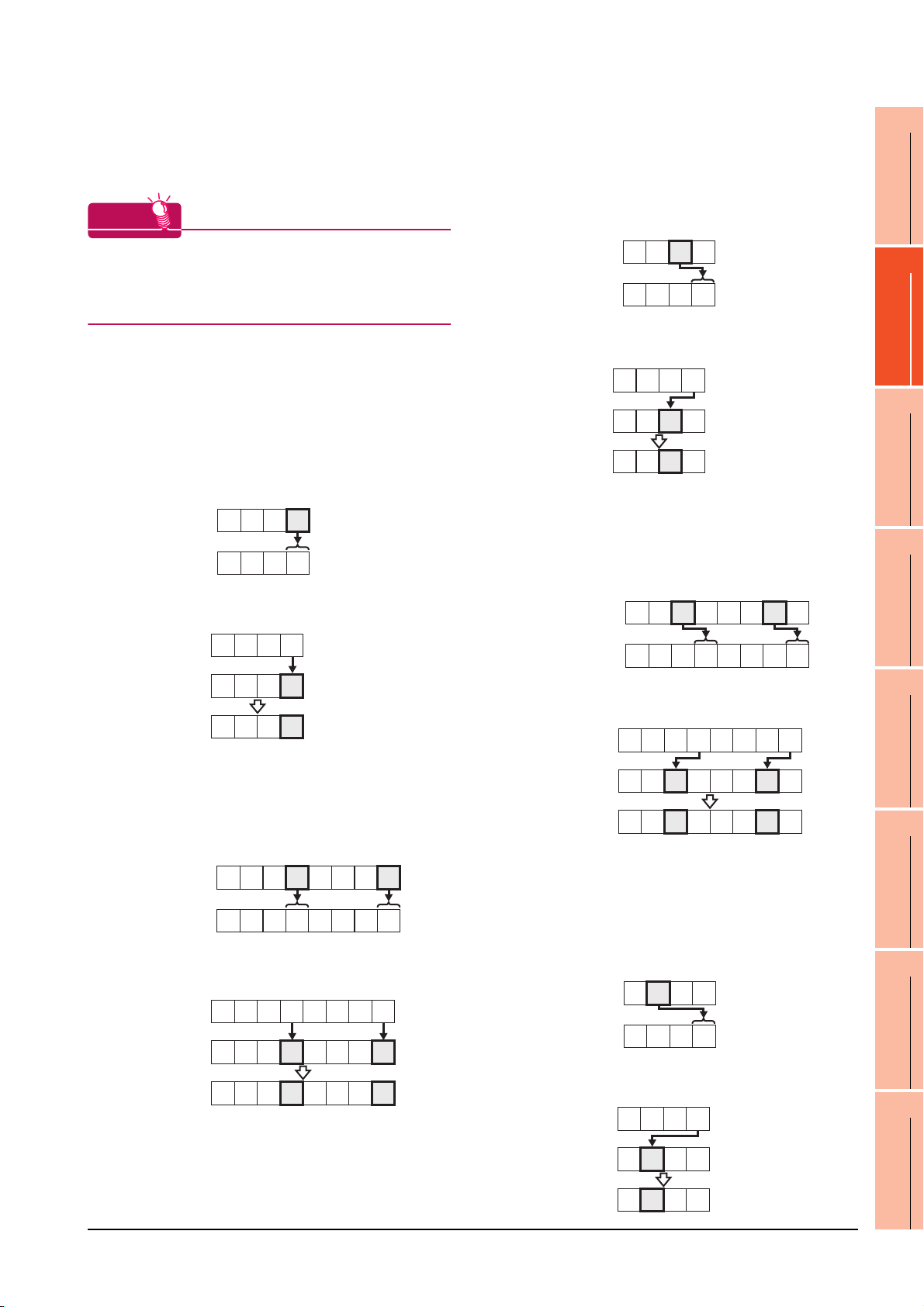
(4) Setting of the mask type (MELSEC-FX)
HINTHINTHINT
BM0
Monitor value
H
4321
0001
H
BM0
(Before writing)
(After writing)
BM0
Input value
H
4321
0000
H
0001
H
BM0
Monitor value
H
4321
0002
H
BM0
(Before writing)
(After writing)
BM0
Input value
H
4321
0000
H
0010
H
H
BM0
87654321
00060002
H
Monitor value
H
BM0
87654321
00000000
H
Input value
BM0
00500010
H
(Before writing)
(After writing)
BM0
Monitor value
H
4321
0003
H
BM0
(Before writing)
(After writing)
BM0
Input value
H
4321
0000
H
0100
H
Set the item for monitoring or writing only the specified
bits of the buffer memory.
Mask type
The mask type is effective when using for the buffer
memories divided per 4 bits, such as an analog input
block.
(c) Mask type 2
•(For 16 bits)
Monitor and write only b4 to b7 of the buffer
memory.
Example:
The monitor value is 0002
H when monitoring
BM0=4321H as mask type 2.
1
PREPARATORY
PROCEDURES FOR
MONITORING
2
(a) Mask type 0
Monitor and write the buffer memory value directly.
(b) Mask type 1
•(For 16 bits)
Monitor and write only b0 to b3 of the buffer
memory.
Example:
The monitor value is 0001
H when monitoring
BM=4321H as mask type 1.
BM0=0001
H when writing input value 4321H to
BM0=0000H as mask type 1.
•(For 32 bits)
Monitor and write only b0 to b3 and b16 to 19 of
the buffer memory.
Example:
The monitor value is 00050001
BM0=87654321
BM0
Monitor value
H as mask type 1.
87654321
00050001
H when monitoring
BM0=00050001H when writing input value
87654321H to BM0=00000000H as mask type 1.
Input value
87654321
BM0=0010
H when writing input value 4321H to
BM0=0000H as mask type 2.
DEVICE RANGE
THAT CAN BE SET
3
•(For 32 bits)
ACCESS RANGE
Monitor and write only b4 to b7 and b20 to 23 of
the buffer memory.
Example:
The monitor value is 00060002
H when monitoring
FOR MONITORING
4
BM0=87654321H as mask type 2.
HOW TO MONITOR
REDUNTANT
SYSTEM
5
BM0=00500010
87654321H to BM0=00000000H as mask type 2.
H when writing input value
BUS CONNECTION
6
(d) Mask type 3
H
H
H
•(For 16 bits)
Monitor and write only b8 to b11 of the buffer
memory.
Example:
The monitor value is 0003
BM0=4321
H as mask type 3.
H when monitoring
DIRECT
CONNECTION TO
CPU
7
BM0
(Before writing)
BM0
(After writing)
00000000
00050001
H
BM0=0100
H
2. DEVICE RANGE THAT CAN BE SET
BM0=0000
H when writing input value 4321H to
H as mask type 3.
2 - 5
COMPUTER LINK
CONNECTION
8
ETHERNET
CONNECTION
Page 96

• (For 32 bits)
H
BM0
87654321
00000000
H
Input value
BM0
05000100
H
(Before writing)
(After writing)
BM0
(Before writing)
(After writing)
BM0
Input value
H
4321
0000
H
1000
H
H
BM0
87654321
00650021
H
Monitor value
Monitor and write only b8 to b11 and b28 to 31 of
the buffer memory.
Example:
The monitor value is 00070003
BM0=87654321
BM0
Monitor value
H as mask type 3.
87654321
00070003
H when monitoring
H
H
BM0=05000100H when writing input value
87654321H to BM0=00000000H as mask type 3.
(f) Mask type 5
•(For 16 bits)
Monitor and write only b0 to b7 of the buffer
memory.
Example:
The monitor value is 0021
H when monitoring
BM0=4321H as mask type 5.
BM0
Monitor value
BM0=0021
4321
0021
H when writing input value 4321H to
H
H
BM0=0000H as mask type 5.
Input value
4321
H
(e) Mask type 4
• (For 16 bits)
Monitor and write only b12 to b15 of the buffer
memory.
Example:
The monitor value is 0004
BM0=4321
Monitor value
H as mask type 4.
BM0
4321
0004
BM0=1000H when writing input value 4321H to
BM0=0000
H as mask type 4.
• (For 32 bits)
Monitor and write only b12 to b15 and b28 to 31
of the buffer memory.
Example:
The monitor value is 00080004
BM0=87654321H as mask type 4.
BM0
87654321
Monitor value
BM0=50001000
87654321
Input value
BM0
(Before writing)
BM0
(After writing)
2 - 6
00080004
H for writing input value
H to BM0=00000000H as mask type 4.
87654321
00000000
50001000
2. DEVICE RANGE THAT CAN BE SET
H when monitoring
H
H
H when monitoring
BM0
(Before writing)
BM0
(After writing)
0000
0021
H
H
•(For 32 bits)
Monitor and write only b0 to b7 and b16 to 23 of
the buffer memory.
Example:
The monitor value is 00650021H when monitoring
BM0=87654321
BM0=00650021
H as mask type 5.
H when writing input value
87654321H to BM0=00000000H as mask type 5.
Input value
BM0
(Before writing)
BM0
(After writing)
87654321
00000000
00650021
H
H
H
(g) Mask type 6
•(For 16 bits)
Monitor and write only b8 to b15 of the buffer
memory.
Example:
The monitor value is 0043
H
H
BM0=4321
Monitor value
BM0=2100
H
H
H
BM0=0000
Input value
BM0
(Before writing)
BM0
(After writing)
H as mask type 6.
BM0
4321
0043
H when writing input value 4321H to
H as mask type 6.
4321
0000
2100
H when monitoring
H
H
H
H
H
Page 97

•(For 32 bits)
H
BM0
87654321
00000000
H
Input value
BM0
65002100
H
(Before writing)
(After writing)
Monitor and write only b8 to b15 and b24 to 31 of
the buffer memory.
Example:
The monitor value is 00870043
BM0=87654321
BM0
Monitor value
H as mask type 6.
87654321
00870043
H when monitoring
H
H
1
PREPARATORY
PROCEDURES FOR
MONITORING
2
BM0=65002100
H when writing input value
87654321H to BM0=00000000H as mask type 6.
(5) Setting of the module No. (MELSEC-FX)
Set the module No. of the special function unit or
special function block to monitor or write.
The module No.0 to No.7 are assigned in order for the
nearest module or block from the main unit. For details
of the module No., refer to the following.
User's Manual (Hardware) of MELSEC-FX
(a) Direct specification
Specify the module No. (No.0 to No.7) of the
special function unit or special function block
directly, to monitor or write when setting the
devices.
(b) Indirect specification
*1
Specify the module No. of the special function unit
or special function block indirectly, to monitor or
write when setting the devices, by using the 16-bit
GOT internal data register (GD10 to GD25).
When specifying the station No. from 100 to 115 on
GT Designer3, the value of GD10 to GD25
corresponding to the module No. will be the
module No. of the special function unit or special
function block.
DEVICE RANGE
THAT CAN BE SET
3
ACCESS RANGE
FOR MONITORING
4
HOW TO MONITOR
REDUNTANT
SYSTEM
5
BUS CONNECTION
6
Module No.
100 GD10
101 GD11
::
114 G D24
115 G D25
Compatible
device
*1 The module No. cannot be specified indirectly for the multi-
drop connection.
Setting range
0 to 7
For the setting other than the above,
error (dedicated device is out of range)
will occur.
If a non-existent module No. is set, a
timeout error occurs.
2. DEVICE RANGE THAT CAN BE SET
DIRECT
CONNECTION TO
CPU
7
COMPUTER LINK
CONNECTION
8
ETHERNET
CONNECTION
2 - 7
Page 98

2.1 MELSEC-QnU/DC, Q17nD/M/NC/DR, CRnD-700
The table below shows the device ranges in [MELSEC-
*10
QnU/DC, Q17nD/M/NC/DR, CRnD-700]
as the
controller type.
Device name
*7
Setting range
Input (X) X0 to X3FFF
Output (Y) Y0 to Y3FFF
Internal relay (M)
*4*6*11
M0 to M61439
Latch relay (L) L0 to L32767
Annunciator (F) F0 to F32767
Link relay (B)
*6
Timer
*6
Counter
*4
Contact (TT) TT0 to TT32767
Coil (TC) TC0 to TC32767
Contact (CT) CT0 to CT32767
Coil (CC) CC0 to CC32767
B0 to B9FFFF
Special relay (SM) SM0 to SM2255
Retentive
Bit device
timer
Contact (SS) SS0 to SS32767
*6
Coil (SC) SC0 to SC32767
Step relay (S) S0 to S32767
Link special relay (SB) SB0 to SB7FFF
Specified bit of the
following word devices
Word device bit
(Except Timer, Counter,
Retentive timer, Index
register and Buffer
memory)
Device No.
representation
Hexadecimal
Decimal
Hexadecimal
Decimal
Hexadecimal
―
Device name
Data register (D)
*7
*4*6*11
Special data register (SD)
Link register (W)
*4
Timer (current value) (TN)
Counter (current value)
*6
(CN)
Retentive timer
(current value) (SN)
*6
Link special register (SW)
File register (R)
Extension
file register
*1
(ER)
*1*2
Block 0 to 255
Device ER0 to ER32767
Extension file register
*1*3*4
(ZR)
*6
Setting range
D0 to D4910079
SD0 to SD2255
W0 to W4AEBFF
TN0 to TN32767
CN0 to CN32767
SN0 to SN32767
SW0 to SW7FFF
R0 to R32767
ZR0 to ZR4849663
Index register (Z) Z0 to Z19
Device No.
representation
Decimal
Hexadecimal
Decimal
Hexadecimal
Decimal
Buffer memory
(Intelligent function module)
*5
(BM)
Buffer memory
Word device
(Intelligent function module)
*4*5
(G)
*8*9
Ww
*8*9
Wr
Multiple CPU high speed
transmission memory (U3E0)
Multiple CPU high speed
transmission memory (U3E1)
Multiple CPU high speed
transmission memory (U3E2)
Multiple CPU high speed
transmission memory (U3E3)
BM0 to BM32767
G0 to G65535
Ww0 to Ww1FFF
Wr0 to Wr1FFF
U3E010000 to U3E024335
to
U3E110000
U3E210000
U3E310000
U3E124335
to
U3E224335
to
U3E324335
Hexadecimal
Motion device (#) #0 to #12287 Decimal
Converting the above bit
Bit device word
*8*12
devices into words
(Except Timer, Counter
and Retentive timer)
*1 Do not set a file register by GT Designer3 when executing
multiple programs with the file of the file register set at [Use
the same file name as the program] by the PLC parameter of
GX Developer.
Otherwise, read/write at GOT will be erroneous.
*2 Available for file register of block No. switched with the RSET
instruction.
*3 Available for file register of block No. of file name switched
with the QDRSET instruction.
*4 GOT treats them in units of 32k (32768 points).
*5 Only the intelligent function module on the station connected
to GOT can be specified.
Set within the address range of the buffer memory existing in
the target intelligent function module.
*6 Do not use local devices set in the MELSEC-Q system.
Otherwise, normal monitoring is not performed.
*7 Even though Universal model QCPU processes 64-bit data,
the GOT cannot monitor 64-bit data.
*8 This is not supported by GT10.
*9 This cannot be monitored when in GOT multi-drop
connection.
*10 For GT14, GT11 and GT10, the controller type is as follows.
• GT14, GT11: MELSEC-QnU/DC, Q17nD/M/NC/DR
• GT10: MELSEC-QnU/DC
*11 For monitoring the internal relay (M) or data register (D) of a
C Controller module, configure the settings related to the
device functions in the device setting tab of the language
controller setting utility.
*12 The device No. must be set in multiples of 16.
―
2 - 8
2. DEVICE RANGE THAT CAN BE SET
2.1 MELSEC-QnU/DC, Q17nD/M/NC/DR, CRnD-700
Page 99

2.2 MELSEC-L
1
The device ranges that can be set when selecting
[MELSEC-L] as the controller type are as follows.
Device name Setting range
Input (X) X0 to X3FFF
Output (Y) Y0 to Y3FFF
Internal relay (M)
Latch relay (L) L0 to L32767
Annunciator (F) F0 to F32767
Link relay (B)
*6
Timer
Counter
Special relay (SM) SM0 to SM2047
Bit device
Retentive
*6
timer
Step relay (S) S0 to S8191
Link special relay (SB) SB0 to SB7FFF
Word device bit
Data register (D)
Special data register (SD)
Link register (W)
Timer (current value) (TN)
Counter (current value)
*6
(CN)
Retentive timer
(current value) (SN)
Link special register (SW)
File register (R)
Extension file register
*1*3*4
(ZR)
Index register (Z) Z0 to Z19
Word device
Buffer memory
(Intelligent function module)
*5
(BM)
Buffer memory
(Intelligent function module)
*4*5
(G)
*7*8
Ww
*7*8
Wr
Bit device word
*4*6
*4
Contact (TT) TT0 to TT32767
Coil (TC) TC0 to TC32767
Contact (CT) CT0 to CT32767
*6
Coil (CC) CC0 to CC32767
Contact (SS) SS0 to SS32767
Coil (SC) SC0 to SC32767
*4*6
*4
*1*2
*7*9
M0 to M61439
B0 to BEFFF
Specified bit of the
following word devices
(Except Timer, Counter,
Retentive timer, Index
register and Buffer
D0 to D421887
SD0 to SD2047
W0 to W66FFF
*6
TN0 to TN32767
CN0 to CN32767
SN0 to SN32767
*6
SW0 to SW7FFF
R0 to R32767
ZR0 to ZR393215
BM0 to BM32767
G0 to G65535
Ww0 to Ww1FFF
Wr0 to Wr1FFF
Converting the above bit
devices into words
(Except Timer contact
and Counter contact)
memory)
representation
Hexadecimal
Hexadecimal
Hexadecimal
Hexadecimal
Hexadecimal
Hexadecimal
Device No.
Decimal
Decimal
―
Decimal
Decimal
Decimal
―
*1 Do not set a file register by GT Designer3 when executing
multiple programs with the file of the file register set at [Use
the same file name as the program] by the PLC parameter of
GX Developer.
Otherwise, read/write at GOT will be erroneous.
*2 Available for file register of block No. switched with the RSET
instruction.
*3 Available for file register of block No. of file name switched
with the QDRSET instruction.
*4 GOT treats them in units of 32k (32768 points).
*5 Only the intelligent function module on the station connected
to GOT can be specified.
Set within the address range of the buffer memory existing in
the target intelligent function module.
*6 Do not use local devices set in the MELSEC-L system.
Otherwise, normal monitoring is not performed. (The data
register (D) can be used for D32768 or later.)
*7 This is not supported by GT10.
*8 This cannot be monitored when in GOT multi-drop
connection.
*9 The device No. must be set in multiples of 16.
PREPARATORY
PROCEDURES FOR
MONITORING
2
DEVICE RANGE
THAT CAN BE SET
3
ACCESS RANGE
FOR MONITORING
4
HOW TO MONITOR
REDUNTANT
SYSTEM
5
BUS CONNECTION
6
DIRECT
CONNECTION TO
CPU
7
COMPUTER LINK
CONNECTION
8
2. DEVICE RANGE THAT CAN BE SET
2.2 MELSEC-L
2 - 9
ETHERNET
CONNECTION
Page 100

2.3 MELSEC-QnA/Q/QS, MELDAS C6 *
The device ranges that can be set when selecting
*13
[MELSEC-QnA/Q/QS, MELDAS C6*]
as the controller
type are as follows.
Device name
Input (X) X0 to X3FFF
Output (Y) Y0 to Y3FFF
Internal relay (M)
Latch relay (L) L0 to L32767
Annunciator (F) F0 to F32767
Link relay (B) B0 to B7FFF
Timer
Counter
Special relay (SM) SM0 to SM2047
Bit device
Retentive
timer
Step relay (S) S0 to S32767
Link special relay (SB) SB0 to SB7FFF
Word device bit
Data register (D)
Special data register (SD) SD0 to SD2047
Link register (W) W0 to W7FFF
Timer (current value) (TN)
Counter (current value)
*9
(CN)
Retentive timer
(current value) (SN)
Link special register (SW) SW0 to SW7FFF
File register (R)
Extension
file register
*1*10*11
(ER)
Extension file register
*1*3*4*10*11
(ZR)
Word device
Index register (Z) Z0 to Z15
Buffer memory
(Intelligent function module)
*5*10*11
(BM)
Buffer memory
(Intelligent function module)
*4*5*10*11
(G)
*10*11
Ww
*10*11
Wr
Bit device word
*7 *8 *12
*9
Contact (TT) TT0 to TT32767
*9
Coil (TC) TC0 to TC32767
Contact (CT) CT0 to CT32767
*9
Coil (CC) CC0 to CC32767
Contact (SS) SS0 to SS32767
*9
Coil (SC) SC0 to SC32767
*9
*9
*9
*1*2
Block 0 to 255
Device R0 to R32767
*6*10
Setting range
M0 to M32767
Specified bit of the
following word devices
(Except Timer, Counter,
Retentive timer, Index
register and Buffer
memory)
D0 to D32767
TN0 to TN32767
CN0 to CN32767
SN0 to SN32767
R0 to R32767
ZR0 to
BM0 to BM32767
G0 to G65535
Ww0 to Ww1FFF
Wr0 to Wr1FFF
Converting the above bit
devices into words
(Except Timer, Counter
and Retentive timer)
ZR1042431
representation
Hexadecimal
Hexadecimal
Hexadecimal
Hexadecimal
Hexadecimal
Hexadecimal
Device No.
Decimal
Decimal
―
Decimal
Decimal
Decimal
―
*1 Do not set a file register by GT Designer3 when executing
multiple programs with the file of the file register set at [Use
the same file name as the program] by the PLC parameter of
GX Developer.(Except MELSEC-QnA)
Otherwise, read/write at GOT will be erroneous.
*2 Available for file register of block No. switched with the RSET
instruction.
*3 Available for file register of block No. of file name switched
with the QDRSET instruction.
*4 GOT treats them in units of 32k (32768 points).
*5 Only the intelligent function module on the station connected
to GOT can be specified.
Set within the address range of the buffer memory existing in
the target intelligent function module.
*6 The device No. must be set in multiples of 16.
*7 When monitoring MELDAS C6/64, if a word device outside
the range is set, the value becomes indefinite.
When a bit device outside the range is set, the object may
not be displayed or the set function may fail to operate.
Check the set device using the device list of GT Designer3.
*8 Devices used by the MELDAS C6/64 system cannot be
used.
*9 Do not use local devices set in the MELSEC-Q system.
Otherwise, normal monitoring is not performed.
*10 This is not supported by GT10.
*11 This cannot be monitored when in GOT multi-drop
connection.
*12 Only reading is possible from QS001CPU.
*13 For GT14, GT11 and GT10, the controller type is as follows.
• GT14, GT11: MELSEC-QnA/Q, MELDAS C6 *
• GT10: MELSEC-QnA/Q
2 - 10
2. DEVICE RANGE THAT CAN BE SET
2.3 MELSEC-QnA/Q/QS, MELDAS C6 *
 Loading...