

Page 1

MELSEC iQ-F
FX5U User's Manual (Hardware)
Page 2

Page 3
SAFETY PRECAUTIONS
WARNING
Indicates that incorrect handling may cause hazardous conditions, resulting in
death or severe injury.
CAUTION
Indicates that incorrect handling may cause hazardous conditions, resulting in
minor or moderate injury or property damage.
(Read these precautions before use.)
Before using this product, please read this manual and the relevant manuals introduced in this manual carefully and pay full
attention to safety in order to handle the product correctly.
This manual classifies the safety precautions into two categories: [ WARNING] and [ CAUTION].
Depending on the circumstances, procedures indicated by [ CAUTION] may also cause severe injury.
It is important to follow all precautions for personal safety.
Store this manual in a safe place so that it can be read whenever necessary. Always forward it to the end user.
[DESIGN PRECAUTIONS]
WARNING
● Make sure to set up the following safety circuits outside the PLC to ensure safe system operation
even during external power supply problems or PLC failure. Otherwise, malfunctions may cause
serious accidents.
- Most importantly, set up the following: an emergency stop circuit, a protection circuit, an interlock
circuit for opposite movements (such as forward vs. reverse rotation), and an interlock circuit to
prevent damage to the equipment at the upper and lower positioning limits.
- Note that when the CPU module detects an error, such as a watchdog timer error, during self-
diagnosis, all outputs are turned off. Also, when an error that cannot be detected by the CPU
module occurs in an input/output control block, output control may be disabled. External circuits
and mechanisms should be designed to ensure safe machine operation in such a case.
- Note that the output current of the 24 V DC service power supply varies depending on the model
and the absence/presence of extension modules. If an overload occurs, the voltage automatically
drops, inputs in the PLC are disabled, and all outputs are turned off. External circuits and
mechanisms should be designed to ensure safe machine operation in such a case.
- Note that when an error occurs in a relay or transistor of an output circuit, the output might stay on
or off. For output signals that may lead to serious accidents, external circuits and mechanisms
should be designed to ensure safe machine operation.
● Construct an interlock circuit in the program so that the whole system always operates on the safe
side before executing the control (for data change) of the PLC in operation.
Read the manual thoroughly and ensure complete safety before executing other controls (for program
change, parameter change, forced output and operation status change) of the PLC in operation.
Otherwise, the machine may be damaged and accidents may occur due to erroneous operations.
● In an output circuit, when a load current exceeding the current rating or an overcurrent caused by a
load short-circuit flows for a long time, it may cause smoke and fire. To prevent this, configure an
external safety circuit, such as a fuse.
● For the operating status of each station after a communication failure of the network, refer to relevant
manuals for the network. Incorrect output or malfunction may result in an accident.
1
Page 4

[DESIGN PRECAUTIONS]
CAUTION
● When an inductive load such as a lamp, heater, or solenoid valve is controlled, a large current
(approximately ten times greater than normal) may flow when the output is turned from off to on. Take
proper measures so that the flowing current does not exceed the value corresponding to the
maximum load specification of the resistance load.
● After the CPU module is powered on or is reset, the time taken to enter the RUN status varies
depending on the system configuration, parameter settings, and/or program size.
Design circuits so that the entire system will always operate safely, regardless of this variation in time.
● Simultaneously turn on and off the power supplies of the CPU module and extension modules.
● If a long-time power failure or an abnormal voltage drop occurs, the PLC stops, and output is turned
off. When the power supply is restored, it will automatically restart (when the RUN/STOP/RESET
switch is on RUN side).
[INSTALLATION PRECAUTIONS]
WARNING
● Make sure to cut off all phases of the power supply externally before attempting installation or wiring
work. Failure to do so may cause electric shock or damage to the product.
● Use the product within the generic environment specifications described in Page 17 Generic
Specifications of this manual.
Never use the product in areas with excessive dust, oily smoke, conductive dusts, corrosive gas (salt
air, Cl
condensation, or rain and wind.
If the product is used in such conditions, electric shock, fire, malfunctions, deterioration or damage
may occur.
, H2S, SO2 or NO2), flammable gas, vibration or impacts, or expose it to high temperature,
2
2
Page 5

[INSTALLATION PRECAUTIONS]
CAUTION
● Do not touch the conductive parts of the product directly. Doing so may cause device failures or
malfunctions.
● When drilling screw holes or wiring, make sure that cutting and wiring debris do not enter the
ventilation slits of the PLC. Failure to do so may cause fire, equipment failures or malfunctions.
● For product supplied together with a dust proof sheet, the sheet should be affixed to the ventilation
slits before the installation and wiring work in order to block foreign objects such as cutting and wiring
debris.
However, when the installation work is completed, make sure to remove the sheet to provide
adequate ventilation. Failure to do so may cause fire, equipment failures or malfunctions.
● Install the product on a flat surface. If the mounting surface is rough, undue force will be applied to the
PC board, thereby causing nonconformities.
● Install the product securely using a DIN rail or mounting screws.
● Connect the expansion board and expansion adapter securely to their designated connectors. Loose
connections may cause malfunctions.
● Make sure to affix the expansion board with tapping screws. Tightening torque should follow the
specifications in the manual. If the screws are tightened outside of the specified torque range, poor
connections may cause malfunctions.
● Work carefully when using a screwdriver during product installation. Failure to do so may cause
damage to the product or accidents.
● Connect the extension cables, peripheral device cables, input/output cables and battery connecting
cable securely to their designated connectors. Loose connections may cause malfunctions.
● When using an SD memory card, insert it into the SD memory card slot. Check that it is inserted
completely. Poor contact may cause malfunction.
● Turn off the power to the PLC before attaching or detaching the following devices. Failure to do so
may cause device failures or malfunctions.
- Peripheral devices, expansion board and expansion adapter
- Extension modules and bus conversion module
-Battery
3
Page 6

[WIRING PRECAUTIONS]
WARNING
● Make sure to cut off all phases of the power supply externally before attempting installation or wiring
work. Failure to do so may cause electric shock or damage to the product.
● Make sure to attach the terminal cover, provided as an accessory, before turning on the power or
initiating operation after installation or wiring work. Failure to do so may cause electric shock.
● The temperature rating of the cable should be 80 or more.
● Make sure to wire the screw terminal block in accordance with the following precautions. Failure to do
so may cause electric shock, equipment failures, a short-circuit, wire breakage, malfunctions, or
damage to the product.
- Wire terminals should follow the dimensions described in the manual.
- Tightening torque should follow the specifications in the manual.
- Tighten the screws using a Phillips-head screwdriver No. 2 (shaft diameter 6 mm (0.24") or less).
Make sure that the screwdriver does not touch the partition part of the terminal block.
● Make sure to wire the terminal block (European type) in accordance with the following precautions.
Failure to do so may cause electric shock, equipment failures, a short-circuit, wire breakage,
malfunctions, or damage to the product.
- Wire terminals should follow the dimensions described in the manual.
- Tightening torque should follow the specifications in the manual.
- Twist the ends of stranded wires and make sure that there are no loose wires.
- Do not solder-plate the electric wire ends.
- Do not connect more than the specified number of wires or electric wires of unspecified size.
- Affix the electric wires so that neither the terminal block nor the connected parts are directly
stressed.
[WIRING PRECAUTIONS]
CAUTION
● Do not supply power to the [24+] and [24V] terminals (24 V DC service power supply) on the CPU
module or extension modules. Doing so may cause damage to the product.
● Perform class D grounding (grounding resistance: 100 or less) of the grounding terminal on the
2
CPU module and extension modules with a wire 2 mm
However, do not use common grounding (refer to Page 78 Grounding) with heavy electrical
systems.
● Connect the power supply wiring to the dedicated terminals described in this manual. If an AC power
supply is connected to a DC input/output terminal or DC power supply terminal, the PLC will burn out.
● Do not wire vacant terminals externally. Doing so may cause damage to the product.
● Install module so that excessive force will not be applied to terminal blocks, power connectors, I/O
connectors, communication connectors, or communication cables. Failure to do so may result in wire
damage/breakage or PLC failure.
or thicker.
4
Page 7

CAUTION
● Make sure to observe the following precautions in order to prevent any damage to the machinery or
accidents due to malfunction of the PLC caused by abnormal data written to the PLC due to the
effects of noise.
- Do not bundle the power line, control line and communication cables together with or lay them
close to the main circuit, high-voltage line, load line or power line. As a guideline, lay the power
line, control line and connection cables at least 100 mm (3.94") away from the main circuit, highvoltage line, load line or power line.
- Ground the shield of the shield wire or shielded cable at one point on the PLC. However, do not
use common grounding with heavy electrical systems.
- Ground the shield of the analog input/output cable at one point on the signal receiving side. Do
not use common grounding with heavy electrical systems.
[STARTUP AND MAINTENANCE PRECAUTIONS]
WARNING
● Do not touch any terminal while the PLC's power is on. Doing so may cause electric shock or
malfunctions.
● Before cleaning or retightening terminals, cut off all phases of the power supply externally. Failure to
do so may cause electric shock.
● Before modifying the program in mid-operation, forcing output, running or stopping the PLC, read
through this manual carefully, and ensure complete safety. An operation error may damage the
machinery or cause accidents.
● Do not change the program in the PLC from two or more peripheral equipment devices at the same
time. (i.e. from an engineering tool and a GOT) Doing so may cause destruction or malfunction of the
PLC program.
● Use the battery for memory backup in conformance to this manual.
- Use the battery for the specified purpose only.
- Connect the battery correctly.
- Do not charge, disassemble, heat, put in fire, short-circuit, connect reversely, weld, swallow or
burn the battery, or apply excessive force (vibration, impact, drop, etc.) to the battery.
- Do not store or use the battery at high temperatures or expose to direct sunlight.
- Do not expose to water, bring near fire or touch liquid leakage or other contents directly.
Incorrect handling of the battery may cause excessive heat, bursting, ignition, liquid leakage or
deformation, and lead to injury, fire or failures and malfunction of facilities and other equipment.
5
Page 8
[STARTUP AND MAINTENANCE PRECAUTIONS]
CAUTION
● Do not disassemble or modify the PLC. Doing so may cause fire, equipment failures, or malfunctions.
*For repair, contact your local Mitsubishi Electric representative.
● After the first use of the SD memory card, do not insert/remove the memory card more than 500 times.
Insertion/removal 500 times or more may cause malfunction.
● Turn off the power to the PLC before connecting or disconnecting any extension cable. Failure to do
so may cause device failures or malfunctions.
● Turn off the power to the PLC before attaching or detaching the following devices. Failure to do so
may cause device failures or malfunctions.
- Peripheral devices, expansion board and expansion adapter
- Extension modules and bus conversion module
- Battery
[OPERATION PRECAUTIONS]
CAUTION
● Construct an interlock circuit in the program to ensure safe operation for the whole system when
executing control (for data change) of the PLC in operation. Read the manual thoroughly and ensure
complete safety before executing other controls (for program change, parameter change, forced
output and operation status change) of the PLC in operation. Otherwise, the machine may be
damaged and accidents may occur by erroneous operations.
[DISPOSAL PRECAUTIONS]
CAUTION
● Please contact a certified electronic waste disposal company for the environmentally safe recycling
and disposal of your device.
● When disposing of batteries, separate them from other waste according to local regulations. For
details on the Battery Directive in EU countries, refer to Page 144 Handling of Batteries and
Devices with Built-in Batteries in EU Member States.
6
Page 9

[TRANSPORTATION PRECAUTIONS]
CAUTION
● When transporting the PLC with the optional battery, turn on the PLC before shipment, confirm that
the battery mode is set in PLC parameters and the BAT LED is OFF, and check the battery life. If the
PLC is transported with the BAT LED on or the battery exhausted, the battery-backed data may be
lost during transportation.
● The PLC is a precision instrument. During transportation, avoid impacts larger than those specified in
the general specifications (Page 17 Generic Specifications) by using dedicated packaging boxes
and shock-absorbing palettes. Failure to do so may cause failures in the PLC. After transportation,
verify operation of the PLC and check for damage of the mounting part, etc.
● When transporting lithium batteries, follow required transportation regulations. For details on the
regulated products, refer to Page 144 Handling of Batteries and Devices with Built-in Batteries in
EU Member States.
● Fumigants that contain halogen materials such as fluorine, chlorine, bromine, and iodine used for
disinfecting and protecting wooden packaging from insects will cause malfunction in Mitsubishi
products. Please take necessary precautions to ensure that residual fumigants do not enter the
product, or treat packaging with methods other than fumigation (heat method). Additionally, disinfect
and protect wood from insects before packing.
INTRODUCTION
This manual contains text, diagrams and explanations which will guide the reader in the correct installation, safe use and
operation of the FX5U Programmable Controllers and should be read and understood before attempting to install or use the
module.
Always forward it to the end user.
Regarding use of this product
• This product has been manufactured as a general-purpose part for general industries, and has not been designed or
manufactured to be incorporated in a device or system used in purposes related to human life.
• Before using the product for special purposes such as nuclear power, electric power, aerospace, medicine or passenger
movement vehicles, consult Mitsubishi Electric.
• This product has been manufactured under strict quality control. However when installing the product where major
accidents or losses could occur if the product fails, install appropriate backup or failsafe functions in the system.
Note
• If in doubt at any stage during the installation of the product, always consult a professional electrical engineer who is
qualified and trained in the local and national standards. If in doubt about the operation or use, please consult the nearest
Mitsubishi Electric representative.
• Since the examples indicated by this manual, technical bulletin, catalog, etc. are used as a reference, please use it after
confirming the function and safety of the equipment and system. Mitsubishi Electric will accept no responsibility for actual
use of the product based on these illustrative examples.
• This manual content, specification etc. may be changed, without a notice, for improvement.
• The information in this manual has been carefully checked and is believed to be accurate; however, if you notice a doubtful
point, an error, etc., please contact the nearest Mitsubishi Electric representative. When doing so, please provide the
manual number given at the end of this manual.
7
Page 10

CONTENTS
SAFETY PRECAUTIONS . . . . . . . . . . . . . . . . . . . . . . . . . . . . . . . . . . . . . . . . . . . . . . . . . . . . . . . . . . . . . . . . . . . .1
INTRODUCTION. . . . . . . . . . . . . . . . . . . . . . . . . . . . . . . . . . . . . . . . . . . . . . . . . . . . . . . . . . . . . . . . . . . . . . . . . . .7
RELEVANT MANUALS . . . . . . . . . . . . . . . . . . . . . . . . . . . . . . . . . . . . . . . . . . . . . . . . . . . . . . . . . . . . . . . . . . . . .12
TERMS . . . . . . . . . . . . . . . . . . . . . . . . . . . . . . . . . . . . . . . . . . . . . . . . . . . . . . . . . . . . . . . . . . . . . . . . . . . . . . . . .12
CHAPTER 1 OUTLINE 14
1.1 Part Names. . . . . . . . . . . . . . . . . . . . . . . . . . . . . . . . . . . . . . . . . . . . . . . . . . . . . . . . . . . . . . . . . . . . . . . . . . . . . 14
Front panel . . . . . . . . . . . . . . . . . . . . . . . . . . . . . . . . . . . . . . . . . . . . . . . . . . . . . . . . . . . . . . . . . . . . . . . . . . . . . 14
Side . . . . . . . . . . . . . . . . . . . . . . . . . . . . . . . . . . . . . . . . . . . . . . . . . . . . . . . . . . . . . . . . . . . . . . . . . . . . . . . . . . . 16
CHAPTER 2 SPECIFICATIONS 17
2.1 Generic Specifications . . . . . . . . . . . . . . . . . . . . . . . . . . . . . . . . . . . . . . . . . . . . . . . . . . . . . . . . . . . . . . . . . . . 17
2.2 Power Supply Specifications . . . . . . . . . . . . . . . . . . . . . . . . . . . . . . . . . . . . . . . . . . . . . . . . . . . . . . . . . . . . . . 18
AC power supply . . . . . . . . . . . . . . . . . . . . . . . . . . . . . . . . . . . . . . . . . . . . . . . . . . . . . . . . . . . . . . . . . . . . . . . . . 18
2.3 Input Specifications . . . . . . . . . . . . . . . . . . . . . . . . . . . . . . . . . . . . . . . . . . . . . . . . . . . . . . . . . . . . . . . . . . . . . 19
24 V DC Input (sink/source) . . . . . . . . . . . . . . . . . . . . . . . . . . . . . . . . . . . . . . . . . . . . . . . . . . . . . . . . . . . . . . . . 19
2.4 Output Specifications . . . . . . . . . . . . . . . . . . . . . . . . . . . . . . . . . . . . . . . . . . . . . . . . . . . . . . . . . . . . . . . . . . . . 21
Relay output . . . . . . . . . . . . . . . . . . . . . . . . . . . . . . . . . . . . . . . . . . . . . . . . . . . . . . . . . . . . . . . . . . . . . . . . . . . . 21
Transistor output . . . . . . . . . . . . . . . . . . . . . . . . . . . . . . . . . . . . . . . . . . . . . . . . . . . . . . . . . . . . . . . . . . . . . . . . . 22
2.5 Input/Output Derating Curve . . . . . . . . . . . . . . . . . . . . . . . . . . . . . . . . . . . . . . . . . . . . . . . . . . . . . . . . . . . . . . 22
2.6 Performance Specifications . . . . . . . . . . . . . . . . . . . . . . . . . . . . . . . . . . . . . . . . . . . . . . . . . . . . . . . . . . . . . . . 23
2.7 Built-in Analog Specifications . . . . . . . . . . . . . . . . . . . . . . . . . . . . . . . . . . . . . . . . . . . . . . . . . . . . . . . . . . . . . 25
Analog input. . . . . . . . . . . . . . . . . . . . . . . . . . . . . . . . . . . . . . . . . . . . . . . . . . . . . . . . . . . . . . . . . . . . . . . . . . . . . 25
Analog output . . . . . . . . . . . . . . . . . . . . . . . . . . . . . . . . . . . . . . . . . . . . . . . . . . . . . . . . . . . . . . . . . . . . . . . . . . . 25
2.8 Communication Specifications . . . . . . . . . . . . . . . . . . . . . . . . . . . . . . . . . . . . . . . . . . . . . . . . . . . . . . . . . . . . 26
Built-in Ethernet communication . . . . . . . . . . . . . . . . . . . . . . . . . . . . . . . . . . . . . . . . . . . . . . . . . . . . . . . . . . . . . 26
Built-in RS-485 communication . . . . . . . . . . . . . . . . . . . . . . . . . . . . . . . . . . . . . . . . . . . . . . . . . . . . . . . . . . . . . . 26
2.9 External Dimensions . . . . . . . . . . . . . . . . . . . . . . . . . . . . . . . . . . . . . . . . . . . . . . . . . . . . . . . . . . . . . . . . . . . . . 27
CPU module . . . . . . . . . . . . . . . . . . . . . . . . . . . . . . . . . . . . . . . . . . . . . . . . . . . . . . . . . . . . . . . . . . . . . . . . . . . . 27
2.10 Terminal Layout . . . . . . . . . . . . . . . . . . . . . . . . . . . . . . . . . . . . . . . . . . . . . . . . . . . . . . . . . . . . . . . . . . . . . . . . . 28
8
CHAPTER 3 PRODUCT LIST 31
3.1 Overall Configuration . . . . . . . . . . . . . . . . . . . . . . . . . . . . . . . . . . . . . . . . . . . . . . . . . . . . . . . . . . . . . . . . . . . . 31
3.2 CPU Module . . . . . . . . . . . . . . . . . . . . . . . . . . . . . . . . . . . . . . . . . . . . . . . . . . . . . . . . . . . . . . . . . . . . . . . . . . . . 32
3.3 I/O Module . . . . . . . . . . . . . . . . . . . . . . . . . . . . . . . . . . . . . . . . . . . . . . . . . . . . . . . . . . . . . . . . . . . . . . . . . . . . . 33
3.4 Intelligent Function Module . . . . . . . . . . . . . . . . . . . . . . . . . . . . . . . . . . . . . . . . . . . . . . . . . . . . . . . . . . . . . . . 34
FX5 intelligent Function Module . . . . . . . . . . . . . . . . . . . . . . . . . . . . . . . . . . . . . . . . . . . . . . . . . . . . . . . . . . . . . 34
FX3 intelligent Function Module . . . . . . . . . . . . . . . . . . . . . . . . . . . . . . . . . . . . . . . . . . . . . . . . . . . . . . . . . . . . . 34
3.5 Expansion Board . . . . . . . . . . . . . . . . . . . . . . . . . . . . . . . . . . . . . . . . . . . . . . . . . . . . . . . . . . . . . . . . . . . . . . . . 35
3.6 Expansion Adapter . . . . . . . . . . . . . . . . . . . . . . . . . . . . . . . . . . . . . . . . . . . . . . . . . . . . . . . . . . . . . . . . . . . . . . 35
3.7 Extension Power Supply Module . . . . . . . . . . . . . . . . . . . . . . . . . . . . . . . . . . . . . . . . . . . . . . . . . . . . . . . . . . . 36
FX5 expansion power supply module . . . . . . . . . . . . . . . . . . . . . . . . . . . . . . . . . . . . . . . . . . . . . . . . . . . . . . . . . 36
FX3 expansion power supply module . . . . . . . . . . . . . . . . . . . . . . . . . . . . . . . . . . . . . . . . . . . . . . . . . . . . . . . . . 36
3.8 Bus Conversion Module . . . . . . . . . . . . . . . . . . . . . . . . . . . . . . . . . . . . . . . . . . . . . . . . . . . . . . . . . . . . . . . . . . 36
3.9 SD Memory Card . . . . . . . . . . . . . . . . . . . . . . . . . . . . . . . . . . . . . . . . . . . . . . . . . . . . . . . . . . . . . . . . . . . . . . . . 36
3.10 Battery . . . . . . . . . . . . . . . . . . . . . . . . . . . . . . . . . . . . . . . . . . . . . . . . . . . . . . . . . . . . . . . . . . . . . . . . . . . . . . . . 37
3.11 Communication Cable. . . . . . . . . . . . . . . . . . . . . . . . . . . . . . . . . . . . . . . . . . . . . . . . . . . . . . . . . . . . . . . . . . . . 37
3.12 Engineering Tool . . . . . . . . . . . . . . . . . . . . . . . . . . . . . . . . . . . . . . . . . . . . . . . . . . . . . . . . . . . . . . . . . . . . . . . . 37
Page 11

CHAPTER 4 SYSTEM CONFIGURATION 38
4.1 Rules of System Configuration . . . . . . . . . . . . . . . . . . . . . . . . . . . . . . . . . . . . . . . . . . . . . . . . . . . . . . . . . . . . 39
4.2 Limitations on the Number of Connected Extension Devices . . . . . . . . . . . . . . . . . . . . . . . . . . . . . . . . . . .41
Number of connected expansion boards. . . . . . . . . . . . . . . . . . . . . . . . . . . . . . . . . . . . . . . . . . . . . . . . . . . . . . . 41
Number of connected expansion adapters . . . . . . . . . . . . . . . . . . . . . . . . . . . . . . . . . . . . . . . . . . . . . . . . . . . . . 41
Number of connected extension modules . . . . . . . . . . . . . . . . . . . . . . . . . . . . . . . . . . . . . . . . . . . . . . . . . . . . . . 42
4.3 Limitation on the Number of Input/Output Points . . . . . . . . . . . . . . . . . . . . . . . . . . . . . . . . . . . . . . . . . . . . . 45
Total number of I/O points and remote I/O points . . . . . . . . . . . . . . . . . . . . . . . . . . . . . . . . . . . . . . . . . . . . . . . . 45
Calculation of number of input/output points . . . . . . . . . . . . . . . . . . . . . . . . . . . . . . . . . . . . . . . . . . . . . . . . . . . . 46
Calculation of number of remote I/O points . . . . . . . . . . . . . . . . . . . . . . . . . . . . . . . . . . . . . . . . . . . . . . . . . . . . . 46
4.4 Limitation on Current Consumption . . . . . . . . . . . . . . . . . . . . . . . . . . . . . . . . . . . . . . . . . . . . . . . . . . . . . . . . 48
Power supply check from the CPU module (current consumption calculation). . . . . . . . . . . . . . . . . . . . . . . . . . 48
Power supply check from the powered input/output module (current consumption calculation) . . . . . . . . . . . . . 49
Power supply check from extension power supply module (current consumption calculation) . . . . . . . . . . . . . . 51
4.5 Rules of System Configuration and Examples of Reconfiguration . . . . . . . . . . . . . . . . . . . . . . . . . . . . . . . 53
System configuration example . . . . . . . . . . . . . . . . . . . . . . . . . . . . . . . . . . . . . . . . . . . . . . . . . . . . . . . . . . . . . . 53
System reconfiguration example . . . . . . . . . . . . . . . . . . . . . . . . . . . . . . . . . . . . . . . . . . . . . . . . . . . . . . . . . . . . . 57
4.6 Numbers and Assignment in System . . . . . . . . . . . . . . . . . . . . . . . . . . . . . . . . . . . . . . . . . . . . . . . . . . . . . . . 62
Module input/output number . . . . . . . . . . . . . . . . . . . . . . . . . . . . . . . . . . . . . . . . . . . . . . . . . . . . . . . . . . . . . . . . 62
Module number of Extension modules . . . . . . . . . . . . . . . . . . . . . . . . . . . . . . . . . . . . . . . . . . . . . . . . . . . . . . . . 62
CONTENTS
CHAPTER 5 INSTALLATION 63
5.1 Installation Location . . . . . . . . . . . . . . . . . . . . . . . . . . . . . . . . . . . . . . . . . . . . . . . . . . . . . . . . . . . . . . . . . . . . . 63
Installation location in enclosure . . . . . . . . . . . . . . . . . . . . . . . . . . . . . . . . . . . . . . . . . . . . . . . . . . . . . . . . . . . . . 63
Spaces in enclosure . . . . . . . . . . . . . . . . . . . . . . . . . . . . . . . . . . . . . . . . . . . . . . . . . . . . . . . . . . . . . . . . . . . . . . 63
Layout in enclosure . . . . . . . . . . . . . . . . . . . . . . . . . . . . . . . . . . . . . . . . . . . . . . . . . . . . . . . . . . . . . . . . . . . . . . . 63
5.2 Examination for Installation Method in Enclosure . . . . . . . . . . . . . . . . . . . . . . . . . . . . . . . . . . . . . . . . . . . . . 64
5.3 Procedures for Installing on and Detaching from DIN Rail . . . . . . . . . . . . . . . . . . . . . . . . . . . . . . . . . . . . . . 65
Preparation for installation . . . . . . . . . . . . . . . . . . . . . . . . . . . . . . . . . . . . . . . . . . . . . . . . . . . . . . . . . . . . . . . . . . 65
Installation of CPU module . . . . . . . . . . . . . . . . . . . . . . . . . . . . . . . . . . . . . . . . . . . . . . . . . . . . . . . . . . . . . . . . . 65
Installation of extension module . . . . . . . . . . . . . . . . . . . . . . . . . . . . . . . . . . . . . . . . . . . . . . . . . . . . . . . . . . . . . 66
Removal of CPU module . . . . . . . . . . . . . . . . . . . . . . . . . . . . . . . . . . . . . . . . . . . . . . . . . . . . . . . . . . . . . . . . . . . 66
5.4 Procedures for Installing Directly (with M4 Screws) . . . . . . . . . . . . . . . . . . . . . . . . . . . . . . . . . . . . . . . . . . . 67
Hole pitches for direct mounting . . . . . . . . . . . . . . . . . . . . . . . . . . . . . . . . . . . . . . . . . . . . . . . . . . . . . . . . . . . . . 67
Hole pitches when extension module connected . . . . . . . . . . . . . . . . . . . . . . . . . . . . . . . . . . . . . . . . . . . . . . . . 69
Installation of CPU module . . . . . . . . . . . . . . . . . . . . . . . . . . . . . . . . . . . . . . . . . . . . . . . . . . . . . . . . . . . . . . . . . 69
Installation of extension module . . . . . . . . . . . . . . . . . . . . . . . . . . . . . . . . . . . . . . . . . . . . . . . . . . . . . . . . . . . . . 70
5.5 Connection Methods for CPU Module and Extension Devices. . . . . . . . . . . . . . . . . . . . . . . . . . . . . . . . . . . 71
Connection of extension devices. . . . . . . . . . . . . . . . . . . . . . . . . . . . . . . . . . . . . . . . . . . . . . . . . . . . . . . . . . . . . 71
Connection method A - connection of an expansion board. . . . . . . . . . . . . . . . . . . . . . . . . . . . . . . . . . . . . . . . . 71
Connection method B - connection of an expansion adapter . . . . . . . . . . . . . . . . . . . . . . . . . . . . . . . . . . . . . . . 72
Connection method C - connection of an extension module to the CPU module . . . . . . . . . . . . . . . . . . . . . . . . 72
Connection method D - connection between extension modules . . . . . . . . . . . . . . . . . . . . . . . . . . . . . . . . . . . . 73
Connection method E - connection of an extension module to the bus conversion module . . . . . . . . . . . . . . . . 73
CHAPTER 6 WIRING 74
6.1 Wiring Preparations . . . . . . . . . . . . . . . . . . . . . . . . . . . . . . . . . . . . . . . . . . . . . . . . . . . . . . . . . . . . . . . . . . . . . 74
Wiring procedure . . . . . . . . . . . . . . . . . . . . . . . . . . . . . . . . . . . . . . . . . . . . . . . . . . . . . . . . . . . . . . . . . . . . . . . . . 74
Removal and installation of removable terminal block . . . . . . . . . . . . . . . . . . . . . . . . . . . . . . . . . . . . . . . . . . . . 75
6.2 Cable Connecting Procedure . . . . . . . . . . . . . . . . . . . . . . . . . . . . . . . . . . . . . . . . . . . . . . . . . . . . . . . . . . . . . . 76
9
Page 12

Screw terminal block . . . . . . . . . . . . . . . . . . . . . . . . . . . . . . . . . . . . . . . . . . . . . . . . . . . . . . . . . . . . . . . . . . . . . . 76
European-type terminal block . . . . . . . . . . . . . . . . . . . . . . . . . . . . . . . . . . . . . . . . . . . . . . . . . . . . . . . . . . . . . . . 77
6.3 Grounding . . . . . . . . . . . . . . . . . . . . . . . . . . . . . . . . . . . . . . . . . . . . . . . . . . . . . . . . . . . . . . . . . . . . . . . . . . . . . 78
6.4 Power Supply Wiring. . . . . . . . . . . . . . . . . . . . . . . . . . . . . . . . . . . . . . . . . . . . . . . . . . . . . . . . . . . . . . . . . . . . . 79
Examples of AC power supply wiring . . . . . . . . . . . . . . . . . . . . . . . . . . . . . . . . . . . . . . . . . . . . . . . . . . . . . . . . . 79
6.5 Input Wiring . . . . . . . . . . . . . . . . . . . . . . . . . . . . . . . . . . . . . . . . . . . . . . . . . . . . . . . . . . . . . . . . . . . . . . . . . . . . 83
24 V DC input (Sink and source input type) . . . . . . . . . . . . . . . . . . . . . . . . . . . . . . . . . . . . . . . . . . . . . . . . . . . . 83
Input wiring example . . . . . . . . . . . . . . . . . . . . . . . . . . . . . . . . . . . . . . . . . . . . . . . . . . . . . . . . . . . . . . . . . . . . . . 87
6.6 Output Wiring. . . . . . . . . . . . . . . . . . . . . . . . . . . . . . . . . . . . . . . . . . . . . . . . . . . . . . . . . . . . . . . . . . . . . . . . . . . 89
Relay output . . . . . . . . . . . . . . . . . . . . . . . . . . . . . . . . . . . . . . . . . . . . . . . . . . . . . . . . . . . . . . . . . . . . . . . . . . . . 89
Transistor output . . . . . . . . . . . . . . . . . . . . . . . . . . . . . . . . . . . . . . . . . . . . . . . . . . . . . . . . . . . . . . . . . . . . . . . . . 92
Output wiring example . . . . . . . . . . . . . . . . . . . . . . . . . . . . . . . . . . . . . . . . . . . . . . . . . . . . . . . . . . . . . . . . . . . . . 95
6.7 Analog Wiring . . . . . . . . . . . . . . . . . . . . . . . . . . . . . . . . . . . . . . . . . . . . . . . . . . . . . . . . . . . . . . . . . . . . . . . . . . 98
6.8 Examples of Wiring for Various Uses . . . . . . . . . . . . . . . . . . . . . . . . . . . . . . . . . . . . . . . . . . . . . . . . . . . . . . . 99
Built-in positioning function . . . . . . . . . . . . . . . . . . . . . . . . . . . . . . . . . . . . . . . . . . . . . . . . . . . . . . . . . . . . . . . . . 99
Communication function . . . . . . . . . . . . . . . . . . . . . . . . . . . . . . . . . . . . . . . . . . . . . . . . . . . . . . . . . . . . . . . . . . . 99
High-speed counter . . . . . . . . . . . . . . . . . . . . . . . . . . . . . . . . . . . . . . . . . . . . . . . . . . . . . . . . . . . . . . . . . . . . . . 100
Interruption . . . . . . . . . . . . . . . . . . . . . . . . . . . . . . . . . . . . . . . . . . . . . . . . . . . . . . . . . . . . . . . . . . . . . . . . . . . . 104
Digital Switch . . . . . . . . . . . . . . . . . . . . . . . . . . . . . . . . . . . . . . . . . . . . . . . . . . . . . . . . . . . . . . . . . . . . . . . . . . . 105
Input Matrix . . . . . . . . . . . . . . . . . . . . . . . . . . . . . . . . . . . . . . . . . . . . . . . . . . . . . . . . . . . . . . . . . . . . . . . . . . . . 107
Seven Segment with Latch . . . . . . . . . . . . . . . . . . . . . . . . . . . . . . . . . . . . . . . . . . . . . . . . . . . . . . . . . . . . . . . . 108
CHAPTER 7 OPERATION ADJUSTMENT 110
7.1 Preparation for Operation . . . . . . . . . . . . . . . . . . . . . . . . . . . . . . . . . . . . . . . . . . . . . . . . . . . . . . . . . . . . . . . . 110
Preliminary inspection . . . . . . . . . . . . . . . . . . . . . . . . . . . . . . . . . . . . . . . . . . . . . . . . . . . . . . . . . . . . . . . . . . . . 110
Procedure until operation . . . . . . . . . . . . . . . . . . . . . . . . . . . . . . . . . . . . . . . . . . . . . . . . . . . . . . . . . . . . . . . . . 111
Connection with a personal computer. . . . . . . . . . . . . . . . . . . . . . . . . . . . . . . . . . . . . . . . . . . . . . . . . . . . . . . . 112
7.2 Operation and Test . . . . . . . . . . . . . . . . . . . . . . . . . . . . . . . . . . . . . . . . . . . . . . . . . . . . . . . . . . . . . . . . . . . . . 113
Self-diagnostic function . . . . . . . . . . . . . . . . . . . . . . . . . . . . . . . . . . . . . . . . . . . . . . . . . . . . . . . . . . . . . . . . . . . 113
Monitoring and debugging. . . . . . . . . . . . . . . . . . . . . . . . . . . . . . . . . . . . . . . . . . . . . . . . . . . . . . . . . . . . . . . . . 113
7.3 Running, Stopping, and Resetting. . . . . . . . . . . . . . . . . . . . . . . . . . . . . . . . . . . . . . . . . . . . . . . . . . . . . . . . . 114
Methods of running, stopping, and resetting . . . . . . . . . . . . . . . . . . . . . . . . . . . . . . . . . . . . . . . . . . . . . . . . . . . 114
CHAPTER 8 MAINTENANCE AND INSPECTION 115
8.1 Daily Inspection . . . . . . . . . . . . . . . . . . . . . . . . . . . . . . . . . . . . . . . . . . . . . . . . . . . . . . . . . . . . . . . . . . . . . . . . 115
8.2 Periodic Inspection . . . . . . . . . . . . . . . . . . . . . . . . . . . . . . . . . . . . . . . . . . . . . . . . . . . . . . . . . . . . . . . . . . . . . 115
8.3 Battery . . . . . . . . . . . . . . . . . . . . . . . . . . . . . . . . . . . . . . . . . . . . . . . . . . . . . . . . . . . . . . . . . . . . . . . . . . . . . . . 116
Part names . . . . . . . . . . . . . . . . . . . . . . . . . . . . . . . . . . . . . . . . . . . . . . . . . . . . . . . . . . . . . . . . . . . . . . . . . . . . 116
Specifications . . . . . . . . . . . . . . . . . . . . . . . . . . . . . . . . . . . . . . . . . . . . . . . . . . . . . . . . . . . . . . . . . . . . . . . . . . 116
Battery attachment . . . . . . . . . . . . . . . . . . . . . . . . . . . . . . . . . . . . . . . . . . . . . . . . . . . . . . . . . . . . . . . . . . . . . . 116
Battery replacement . . . . . . . . . . . . . . . . . . . . . . . . . . . . . . . . . . . . . . . . . . . . . . . . . . . . . . . . . . . . . . . . . . . . . 118
Special relay for low battery voltage . . . . . . . . . . . . . . . . . . . . . . . . . . . . . . . . . . . . . . . . . . . . . . . . . . . . . . . . . 119
10
CHAPTER 9 TROUBLESHOOTING 120
9.1 Troubleshooting Procedure . . . . . . . . . . . . . . . . . . . . . . . . . . . . . . . . . . . . . . . . . . . . . . . . . . . . . . . . . . . . . . 120
9.2 Checking with LEDs . . . . . . . . . . . . . . . . . . . . . . . . . . . . . . . . . . . . . . . . . . . . . . . . . . . . . . . . . . . . . . . . . . . . 120
Checking the PWR LED . . . . . . . . . . . . . . . . . . . . . . . . . . . . . . . . . . . . . . . . . . . . . . . . . . . . . . . . . . . . . . . . . . 120
Checking the BAT LED . . . . . . . . . . . . . . . . . . . . . . . . . . . . . . . . . . . . . . . . . . . . . . . . . . . . . . . . . . . . . . . . . . . 120
Checking the ERR LED . . . . . . . . . . . . . . . . . . . . . . . . . . . . . . . . . . . . . . . . . . . . . . . . . . . . . . . . . . . . . . . . . . . 121
Checking the P.RUN LED . . . . . . . . . . . . . . . . . . . . . . . . . . . . . . . . . . . . . . . . . . . . . . . . . . . . . . . . . . . . . . . . . 121
Page 13

9.3 Troubleshooting using the engineering tool . . . . . . . . . . . . . . . . . . . . . . . . . . . . . . . . . . . . . . . . . . . . . . . . 121
Module diagnostics (CPU Diagnostics) . . . . . . . . . . . . . . . . . . . . . . . . . . . . . . . . . . . . . . . . . . . . . . . . . . . . . . . 122
9.4 Error Status and Operations on Occurrence of an Error. . . . . . . . . . . . . . . . . . . . . . . . . . . . . . . . . . . . . . . 123
9.5 Backing Up the Data . . . . . . . . . . . . . . . . . . . . . . . . . . . . . . . . . . . . . . . . . . . . . . . . . . . . . . . . . . . . . . . . . . . . 124
9.6 Canceling Errors . . . . . . . . . . . . . . . . . . . . . . . . . . . . . . . . . . . . . . . . . . . . . . . . . . . . . . . . . . . . . . . . . . . . . . . 124
9.7 Troubleshooting for Each Symptom . . . . . . . . . . . . . . . . . . . . . . . . . . . . . . . . . . . . . . . . . . . . . . . . . . . . . . . 125
I/O operation (CPU module, I/O module) . . . . . . . . . . . . . . . . . . . . . . . . . . . . . . . . . . . . . . . . . . . . . . . . . . . . . 125
PLC write, PLC read . . . . . . . . . . . . . . . . . . . . . . . . . . . . . . . . . . . . . . . . . . . . . . . . . . . . . . . . . . . . . . . . . . . . . 126
Boot operation . . . . . . . . . . . . . . . . . . . . . . . . . . . . . . . . . . . . . . . . . . . . . . . . . . . . . . . . . . . . . . . . . . . . . . . . . . 126
APPENDIX 127
Appendix 1 How to Check the Date of Manufacture . . . . . . . . . . . . . . . . . . . . . . . . . . . . . . . . . . . . . . . . . . . . . . . . 127
Appendix 2 Standards . . . . . . . . . . . . . . . . . . . . . . . . . . . . . . . . . . . . . . . . . . . . . . . . . . . . . . . . . . . . . . . . . . . . . . . . 128
Certification of UL, cUL standards. . . . . . . . . . . . . . . . . . . . . . . . . . . . . . . . . . . . . . . . . . . . . . . . . . . . . . . . . . . 128
Compliance with EC directive (CE Marking) . . . . . . . . . . . . . . . . . . . . . . . . . . . . . . . . . . . . . . . . . . . . . . . . . . . 128
Requirement for compliance with EMC directive . . . . . . . . . . . . . . . . . . . . . . . . . . . . . . . . . . . . . . . . . . . . . . . . 128
Requirement for compliance with LVD directive . . . . . . . . . . . . . . . . . . . . . . . . . . . . . . . . . . . . . . . . . . . . . . . . 129
Caution for compliance with EC Directive . . . . . . . . . . . . . . . . . . . . . . . . . . . . . . . . . . . . . . . . . . . . . . . . . . . . . 129
Appendix 3 I/O Module. . . . . . . . . . . . . . . . . . . . . . . . . . . . . . . . . . . . . . . . . . . . . . . . . . . . . . . . . . . . . . . . . . . . . . . . 132
Product configuration. . . . . . . . . . . . . . . . . . . . . . . . . . . . . . . . . . . . . . . . . . . . . . . . . . . . . . . . . . . . . . . . . . . . . 132
Product list. . . . . . . . . . . . . . . . . . . . . . . . . . . . . . . . . . . . . . . . . . . . . . . . . . . . . . . . . . . . . . . . . . . . . . . . . . . . . 132
Specifications . . . . . . . . . . . . . . . . . . . . . . . . . . . . . . . . . . . . . . . . . . . . . . . . . . . . . . . . . . . . . . . . . . . . . . . . . . 133
External dimensions and component names. . . . . . . . . . . . . . . . . . . . . . . . . . . . . . . . . . . . . . . . . . . . . . . . . . . 138
Terminal layout . . . . . . . . . . . . . . . . . . . . . . . . . . . . . . . . . . . . . . . . . . . . . . . . . . . . . . . . . . . . . . . . . . . . . . . . . 140
Appendix 4 SD Memory Card . . . . . . . . . . . . . . . . . . . . . . . . . . . . . . . . . . . . . . . . . . . . . . . . . . . . . . . . . . . . . . . . . . 141
Part names . . . . . . . . . . . . . . . . . . . . . . . . . . . . . . . . . . . . . . . . . . . . . . . . . . . . . . . . . . . . . . . . . . . . . . . . . . . . 141
Specifications . . . . . . . . . . . . . . . . . . . . . . . . . . . . . . . . . . . . . . . . . . . . . . . . . . . . . . . . . . . . . . . . . . . . . . . . . . 141
Insertion and removal of the SD memory card . . . . . . . . . . . . . . . . . . . . . . . . . . . . . . . . . . . . . . . . . . . . . . . . . 142
Appendix 5 Precautions for Battery Transportation . . . . . . . . . . . . . . . . . . . . . . . . . . . . . . . . . . . . . . . . . . . . . . . . 143
Control-subject product . . . . . . . . . . . . . . . . . . . . . . . . . . . . . . . . . . . . . . . . . . . . . . . . . . . . . . . . . . . . . . . . . . . 143
Precautions for transportation . . . . . . . . . . . . . . . . . . . . . . . . . . . . . . . . . . . . . . . . . . . . . . . . . . . . . . . . . . . . . . 143
Appendix 6 Handling of Batteries and Devices with Built-in Batteries in EU Member States . . . . . . . . . . . . . . 144
Disposal precautions . . . . . . . . . . . . . . . . . . . . . . . . . . . . . . . . . . . . . . . . . . . . . . . . . . . . . . . . . . . . . . . . . . . . . 144
Exportation precautions . . . . . . . . . . . . . . . . . . . . . . . . . . . . . . . . . . . . . . . . . . . . . . . . . . . . . . . . . . . . . . . . . . . 144
CONTENTS
INDEX 145
REVISIONS. . . . . . . . . . . . . . . . . . . . . . . . . . . . . . . . . . . . . . . . . . . . . . . . . . . . . . . . . . . . . . . . . . . . . . . . . . . . .146
WARRANTY . . . . . . . . . . . . . . . . . . . . . . . . . . . . . . . . . . . . . . . . . . . . . . . . . . . . . . . . . . . . . . . . . . . . . . . . . . . .147
TRADEMARKS . . . . . . . . . . . . . . . . . . . . . . . . . . . . . . . . . . . . . . . . . . . . . . . . . . . . . . . . . . . . . . . . . . . . . . . . . .148
11
Page 14

RELEVANT MANUALS
User's manuals for the applicable modules
Manual name <manual number> Description
MELSEC iQ-F FX5U CPU Module Hardware Manual
<JY997D53401>
MELSEC iQ-F FX5 User's Manual (Startup)
<JY997D58201>
MELSEC iQ-F FX5U User's Manual (Hardware)
<JY997D55301> (This manual)
MELSEC iQ-F FX5UC User's Manual (Hardware)
<JY997D61401>
MELSEC iQ-F FX5 User's Manual (Application)
<JY997D55401>
MELSEC iQ-F FX5 Programming Manual (Program Design)
<JY997D55701>
MELSEC iQ-F FX5 Programming Manual (Instructions, Standard
Functions/Function Blocks)
<JY997D55801>
MELSEC iQ-F FX5 User's Manual (Serial Communication)
<JY997D55901>
MELSEC iQ-F FX5 User's Manual (MODBUS Communication)
<JY997D56101>
MELSEC iQ-F FX5 User's Manual (Ethernet Communication)
<JY997D56201>
MELSEC iQ-F FX5 User's Manual (SLMP)
<JY997D56001>
MELSEC iQ-F FX5 User's Manual (Positioning Control)
<JY997D56301>
MELSEC iQ-F FX5 User's Manual (Analog Control)
<JY997D60501>
GX Works3 Operating Manual
<SH-081215ENG>
Describes the details of input/output specifications, wiring and installation of the
FX5U CPU module from MELSEC iQ-F FX5U User's Manual (Hardware).
Performance specifications, procedures before operation, and troubleshooting of the
CPU module.
Describes the details of hardware of the FX5U CPU module, including input/output
specifications, wiring, installation, and maintenance.
Describes the details of hardware of the FX5UC CPU module, including input/output
specifications, wiring, installation, and maintenance.
Describes basic knowledge required for program design, functions of the CPU
module, devices/labels, and parameters.
Describes specifications of ladders, ST, FBD/LD, and other programs and labels.
Describes specifications of instructions and functions that can be used in programs.
Describes N:N network, MELSEC Communication protocol, inverter communication,
non-protocol communication, and predefined protocol support.
Describes MODBUS serial communication.
Describes the functions of the built-in Ethernet port communication function.
Explains methods for the device that is communicating with the CPU module by
SLMP to read and write the data of the CPU module.
Describes the built-in positioning function.
Describes the analog function.
System configuration, parameter settings, and online operations of GX Works3.
TERMS
Unless otherwise specified, this manual uses the following terms.
• indicates a variable part to collectively call multiple models or versions.
(Example) FX5U-32MR/ES, FX5U-32MT/ES FX5U-32M/ES
• For details on the FX3 devices that can be connected with the FX5U CPU module, refer to Page 31 PRODUCT LIST.
Ter ms Description
■Devices
FX5 Generic term for FX5U, and FX5UC PLCs
FX3 Generic term for FX3S, FX3G, FX3GC, FX3U, and FX3UC PLCs
FX5 CPU module Generic term for FX5U CPU module and FX5UC CPU module
FX5U CPU module Generic term for FX5U-32MR/ES, FX5U-32MT/ES, FX5U-32MT/ESS, FX5U-64MR/ES, FX5U-64MT/ES,
FX5U-64MT/ESS, FX5U-80MR/ES, FX5U-80MT/ES, and FX5U-80MT/ESS
FX5UC CPU module Generic term for FX5UC-32MT/D and FX5UC-32MT/DSS
Extension module Generic term for FX5 extension modules and FX3 function modules
• FX5 extension module Generic term for I/O modules, FX5 extension power supply module, and FX5 intelligent function module
• FX3 extension module Generic term for FX3 extension power supply module and FX3 intelligent function module
I/O module Generic term for input modules, output modules, and powered input/output modules
• Input module Generic term for FX5-8EX/ES and FX5-16EX/ES
• Output module Generic term for FX5-8EYR/ES, FX5-8EYT/ES, FX5-8EYT/ESS, FX5-16EYR/ES, FX5-16EYT/ES, and
FX5-16EYT/ESS
Powered input/output module Generic term for FX5-32ER/ES, FX5-32ET/ES, and FX5-32ET/ESS
12
Page 15

Term s Description
Extension power supply module Generic term for FX5 extension power supply module and FX3 extension power supply module
• FX5 extension power supply module Different name for FX5-1PSU-5V
• FX3 extension power supply module Different name for FX3U-1PSU-5V
Intelligent module The abbreviation for intelligent function modules
Intelligent function module Generic term for FX5 intelligent function modules and FX3 intelligent function modules
• FX5 intelligent function module Generic term for FX5 intelligent function modules
• FX3 intelligent function module Different name for FX3 special function blocks
Simple motion module Different name for FX5-40SSC-S
Expansion board Generic term for board for FX5U CPU module
• Communication board Generic term for FX5-232-BD, FX5-485-BD, and FX5-422-BD-GOT
Expansion adapter Generic term for adapter for FX5 CPU module
• Communication adapter Generic term for FX5-232ADP and FX5-485ADP
• Analog adapter Generic term for FX5-4AD-ADP and FX5-4DA-ADP
Bus conversion module Different name for FX5-CNV-BUS
Battery Different name for FX3U-32BL
SD memory card Generic term for NZ1MEM-2GBSD, NZ1MEM-4GBSD, L1MEM-2GBSD and L1MEM-4GBSD SD memory
cards
Abbreviation of Secure Digital Memory Card. Device that stores data using flash memory.
Peripheral device Generic term for engineering tools and GOTs
GOT Generic term for Mitsubishi Graphic Operation Terminal GOT1000 and GOT2000 series
■Software packages
Engineering tool The product name of the software package for the MELSEC programmable controllers
GX Works3 The product name of the software package, SWnDND-GXW3, for the MELSEC programmable controllers
■Manuals
Hardware manual Generic term for manuals enclosed with the product
• FX5U Hardware manual Abbreviation of MELSEC iQ-F FX5U CPU Module Hardware manual
User's manual Generic term for separate manuals
• User's manual (Startup) Abbreviation of MELSEC iQ-F FX5 User's Manual (Startup)
• FX5U User's manual (Hardware) Abbreviation of MELSEC iQ-F FX5U User's Manual (Hardware)
• User's manual (Application) Abbreviation of MELSEC iQ-F FX5 User's Manual (Application)
Programming manual (Program Design) Abbreviation of MELSEC iQ-F FX5 Programming Manual (Program Design)
Programming manual (Instructions, Standard
Functions/Function Blocks)
Communication manual Generic term for MELSEC iQ-F FX5 User's Manual (Serial Communication), MELSEC iQ-F FX5 User's
• Serial communication manual Abbreviation of MELSEC iQ-F FX5 User's Manual (Serial Communication)
• MODBUS communication manual Abbreviation of MELSEC iQ-F FX5 User's Manual (MODBUS Communication)
• Ethernet communication manual Abbreviation of MELSEC iQ-F FX5 User's Manual (Ethernet Communication)
• SLMP manual Abbreviation of MELSEC iQ-F FX5 User's Manual (SLMP)
Positioning manual Abbreviation of MELSEC iQ-F FX5 User's Manual (Positioning Control)
Analog manual Abbreviation of MELSEC iQ-F FX5 User's Manual (Analog Control)
(The 'n' represents a version.)
Abbreviation of MELSEC iQ-F FX5 Programming Manual (Instructions, Standard Functions/Function Blocks)
Manual (MODBUS Communication), MELSEC iQ-F FX5 User's Manual (Ethernet Communication), and
MELSEC iQ-F FX5 User's Manual (SLMP)
13
Page 16
1 OUTLINE
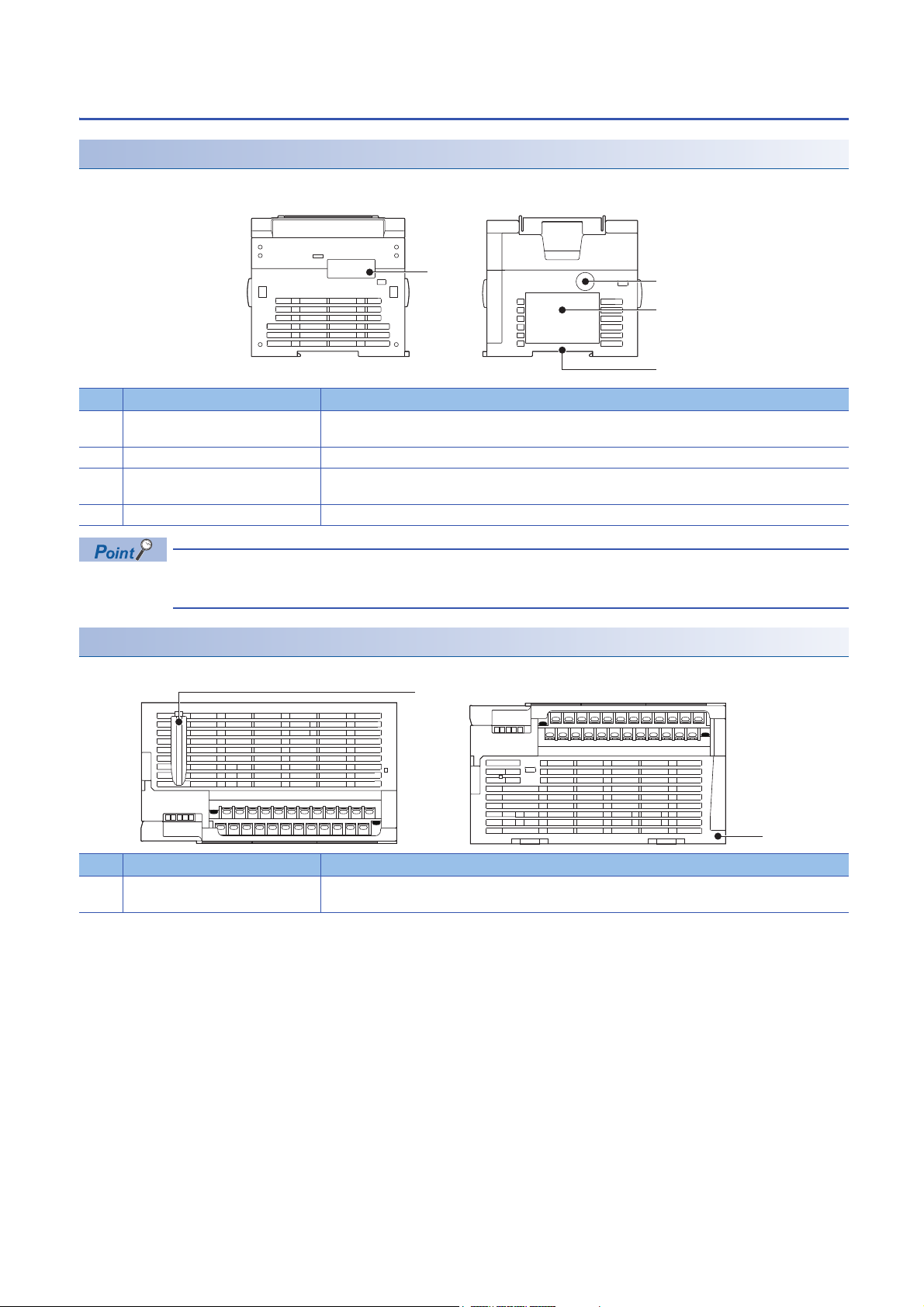
1.1 Part Names
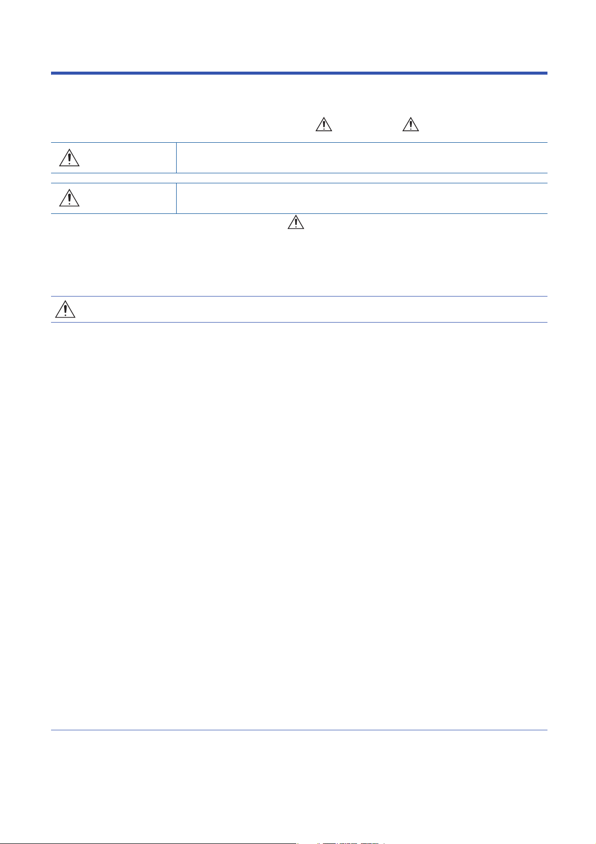
Front panel
[2]
[3]
[6]
[7]
[8]
[9]
[5]
[4]
[10]
[11]
[3]
[2]
[1]
No. Name Description
[1] DIN rail mounting hooks Hook for mounting the CPU module on a DIN rail of DIN46277 (35 mm (1.38") wide).
[2] Expansion adapter connecting
hooks
[3] Terminal block cover Cover for protecting the terminal block.
[4] Built-in Ethernet communication
connector
[5] Top cover Cover for protecting the SD memory card slot, the RUN/STOP/RESET switch, and others.
[6] CARD LED Indicates whether an SD memory card can be used or not.
RD LED Lit when the CPU module is receiving data through built-in RS-485 communication.
SD LED Lit when the CPU module is sending data through built-in RS-485 communication.
SD/RD LED Lit when the CPU module is sending or receiving data through built-in Ethernet communication.
[7] Expansion board connector cover Cover for protecting expansion board connectors, battery, or others.
[8] Input display LED Lit when input is on.
[9] Extension connector cover Cover for protecting the extension connector.
[10] PWR LED Indicates whether the CPU module is powered or not.
ERR LED Indicates the error status of the CPU module. (Page 120 Checking with LEDs)
P.RUN LED Indicates the program running status.
BAT LED Indicates the battery status.
[11] Output display LED Lit when output is on.
When connecting an expansion adapter, secure it with these hooks.
The cover can be opened for wiring. Keep the covers closed while equipment is running (power is on).
Connector for connection with Ethernet-compatible devices. (with cover)
For details, refer to MELSEC iQ-F FX5 User's Manual (Ethernet Communication).
The built-in RS-485 communication terminal block, built-in analog I/O terminal block, RUN/STOP/RESET switch,
SD memory card slot, and others are located under this cover.
Lit: Can be used or cannot be removed.
Flashing: In preparation
Off: Not inserted or can be removed.
Connect the battery under this cover.
Connect the extension cable of an extension module to the extension connector under the cover.
Lit: Powered
Off: Not powered or hardware error (Page 120 Checking with LEDs)
Lit: Error or hardware error
Flashing: Factory default setting, error, hardware error, or resetting
Off: Operating normally
Lit: Operating normally
Flashing: Paused
Off: Stopped or stop error
Flashing: Battery error
Off: Operating normally (Page 120 Checking with LEDs)
14
1 OUTLINE
1.1 Part Names
Page 17
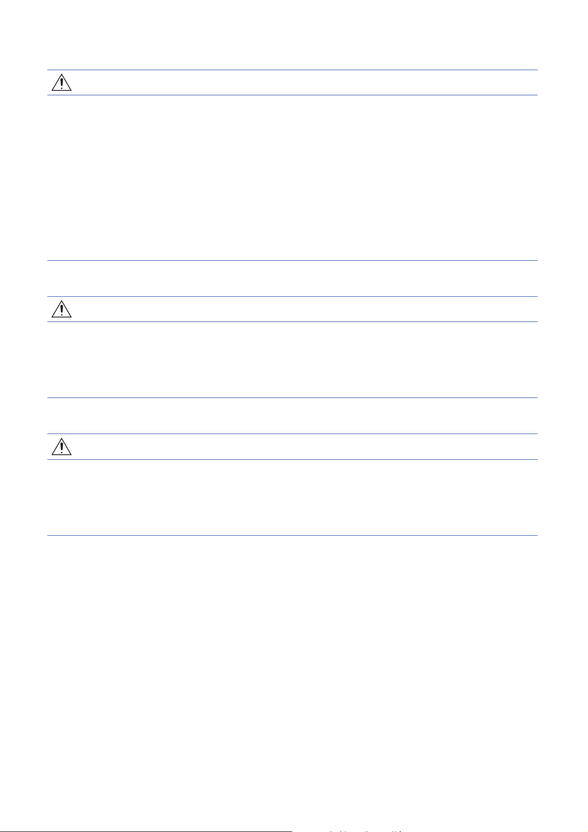
With cover open
[6]
[5]
1
[7]
[4]
[3]
[2]
[8]
[9]
[10]
[1]
No. Name Description
[1] Built-in RS-485 communication
terminal block
[2] RS-485 terminal resistor selector
switch
[3] RUN/STOP/RESET switch Switch for operating the CPU module. (Page 114 Methods of running, stopping, and resetting)
[4] SD memory card disable switch Switch for disabling access to the SD memory card when the card is to be removed.
[5] Built-in analog I/O terminal block Terminal block for using the built-in analog function.
[6] SD memory card slot Slot for inserting an SD memory card.
[7] Expansion board connector Connector for connecting an expansion board.
[8] Extension connector Connector for connecting the extension cable of an extension module.
[9] Battery holder Holder for storing an optional battery.
[10] Battery connector Connector for connecting an optional battery.
Terminal block for connection with RS-485-compatible devices
Switch for switching terminal resistance for built-in RS-485 communication.
RUN: Runs the program
STOP: Stops the program
RESET: Resets the CPU module (hold the switch on the RESET side for approximately 1 second.)
Use a tool such as a screwdriver to operate RS-485 terminal resistor selector switch.
Make sure that the edge of the tool does not damage the switch or the case.
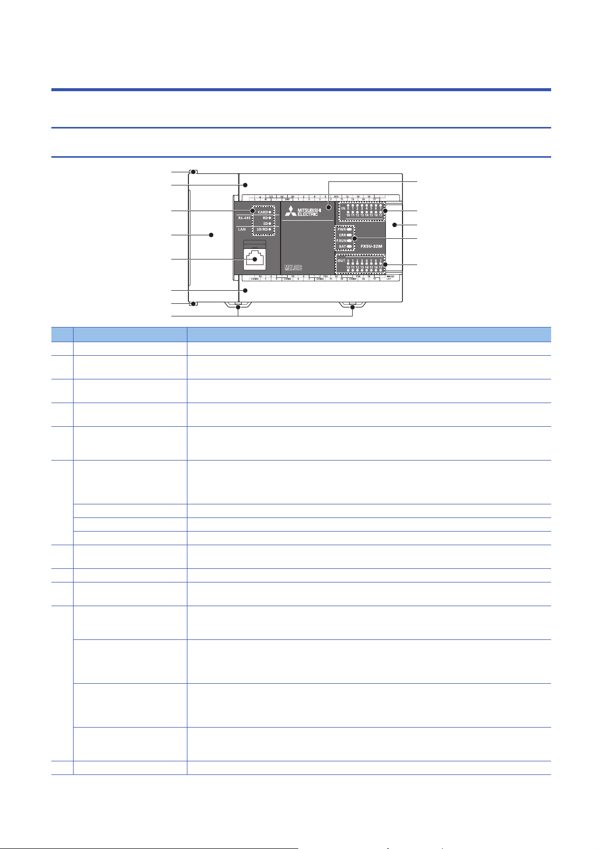
When the terminal block covers are open
[1]
[2]
[2]
[1]
No. Name Description
[1] Terminal block mounting screws Gradually loosen the left and right screws (alternately), and remove the top of the terminal blocks.
[2] Terminal Terminals for power, input, and output.
For details on the terminal layout, refer to Page 28 Terminal Layout.
1 OUTLINE
1.1 Part Names
15
Page 18
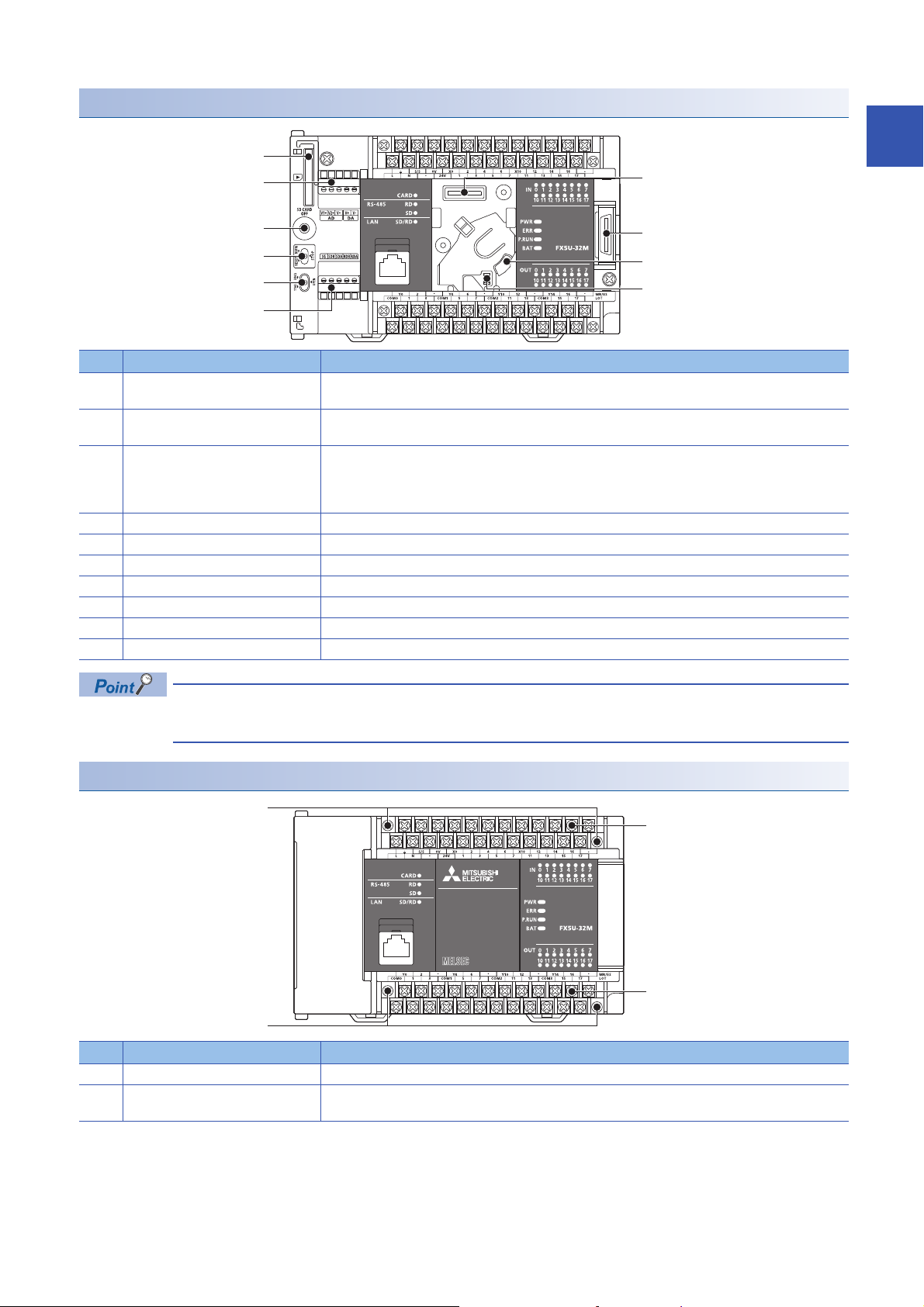
Side
[1]
[1]
Top side Bottom side
Left side/right side
Left side Right side
[1]
[2]
[3]
[4]
No. Name Description
[1] Expansion adapter connector cover Cover for protecting the expansion adapter connector. Connect the expansion adapter to the expansion
[2] Genuine product certification label Genuine product certification label to prevent counterfeiting
[3] Nameplate The product model name, Manufacturer's serial number, power supply specifications, and MAC address are
[4] DIN rail mounting groove The module can be installed on DIN46277 rail (35 mm (1.38") wide).
adapter connector under the cover.
shown.
Products that do not have the genuine product certification label or nameplate are not covered by the
warranty.
Top side/bottom side
No. Name Description
[1] CPU module fixing screw hole Screw holes for fixing the CPU module to the panel. (In the case of FX5U-64M/80M, there are four
screw holes.)
16
1 OUTLINE
1.1 Part Names
Page 19

2 SPECIFICATIONS
The CPU module specifications are explained below.
2.1 Generic Specifications
Item Specifications
Operating ambient temperature
Storage ambient temperature -25 to 75 (-13 to 167 )
Operating ambient humidity 5 to 95%RH, non-condensation
Storage ambient humidity 5 to 95%RH, non-condensation
Vibration resistance
Shock resistance
Noise durability By noise simulator at noise voltage of 1000 Vp-p, noise width of 1 s and period of 30 to 100 Hz
Grounding Class D grounding (grounding resistance: 100 or less) <Common grounding with a heavy electrical system is not
Working atmosphere Free from corrosive or flammable gas and excessive conductive dust
Operating altitude
Installation location Inside a control panel
Overvoltage category
Pollution degree
Equipment class Class 2
*1 The simultaneous ON ratio of available PLC inputs or outputs changes with respect to the ambient temperature, refer to Page 22
Input/Output Derating Curve.
*2 For details on Intelligent function modules, refer to manuals of each product.
*3 The criterion is shown in IEC61131-2.
*4 When the system has equipment which specification values are lower than above mentioned vibration resistance specification values,
the vibration resistance specification of the whole system is corresponding to the lower specification.
*5 For grounding, refer to Page 78
*6 The PLC cannot be used at a pressure higher than the atmospheric pressure to avoid damage.
*7 This indicates the section of the power supply to which the equipment is assumed to be connected between the public electrical power
distribution network and the machinery within premises. Category applies to equipment for which electrical power is supplied from
fixed facilities. The surge voltage withstand level for up to the rated voltage of 300 V is 2500 V.
*8 This index indicates the degree to which conductive material is generated in the environment in which the equipment is used. Pollution
level 2 is when only non-conductive pollution occurs. Temporary conductivity caused by condensation must be expected occasionally.
*3*4
*3
*6
*7
*8
*1
0 to 55 (32 to 131 )
Frequency Acceleration Half amplitude Sweep count
Installed on DIN rail 5 to 8.4 Hz 1.75 mm 10 times each in X, Y, Z directions
Direct installing 5 to 8.4 Hz 3.5 mm
147 m/, Action time: 11 ms, 3 times by half-sine pulse in each direction X, Y, and Z
*5
allowed.>
0 to 2000 m
or less
2 or less
*2
8.4 to 150 Hz 4.9 m/
8.4 to 150 Hz 9.8 m/
(80 min in each direction)
2
Dielectric withstand voltage test and insulation resistance test
Perform dielectric withstand voltage test and insulation resistance test at the following voltages between each terminal and
the CPU module ground terminal.
■ CPU module, I/O module
Between terminals Dielectric
withstand voltage
Between power supply terminal (AC power supply) and ground terminal 1.5 kV AC for one
minute
Between 24 V DC service power supply connected to input terminal (24
V DC) and ground terminal
Between output terminal (relay) and ground terminal 1.5 kV AC for one
Between output terminal (transistor) and ground terminal 500 V AC for one
500 V AC for one
minute
minute
minute
Insulation resistance Remarks
10 M or higher by 500 V DC
insulation resistance tester
2.1 Generic Specifications
2 SPECIFICATIONS
17
Page 20

■Expansion board, expansion adapter
Between terminals Dielectric
withstand
voltage
Between terminal of expansion board and ground terminal Not allowed Not allowed Since the expansion board and
Between terminal of expansion adapter and ground terminal 500 V AC for
one minute
For dielectric withstand voltage test and insulation resistance test of each product, refer to manuals of each product.
Insulation resistance Remarks
CPU module are not insulated, it
is not allowed to perform the
dielectric withstand voltage test
and insulation resistance test
between them.
10 M or higher by 500 V DC
insulation resistance tester
■Intelligent function module
For information concerning dielectric withstand voltage and insulation resistance of intelligent function modules, refer to
manuals of each intelligent function module.
2.2 Power Supply Specifications
The CPU module power supply specifications are explained below.
For the consumption current of extension modules, refer to Page 31 PRODUCT LIST or manuals of each extension
module.
AC power supply
Item Specifications
Rated voltage 100 to 240 V AC
Allowable supply voltage range 85 to 264 V AC
Frequency rating 50/60 Hz
Allowable instantaneous power failure time Operation can be continued upon occurrence of instantaneous power failure for 10 ms or less.
When the supply voltage is 200 V AC, the time can be change to 10 to 100 ms by editing the user
program.
Power fuse FX5U-32M 250 V, 3.15 A Time-lag fuse
FX5U-64M,
FX5U-80M
Rush current FX5U-32M 25 A max. 5 ms or less/100 V AC
FX5U-64M,
FX5U-80M
Power consumption
24 V DC service power
supply capacity
5 V DC power supply
capacity
*1
*2
FX5U-32M 30 W
FX5U-64M 40 W
FX5U-80M 45 W
FX5U-32M 400 mA (Supply capacity when service power supply is used for input circuit of the CPU module )
FX5U-64M 600 mA (Supply capacity when service power supply is used for input circuit of the CPU module)
FX5U-80M 600 mA (Supply capacity when service power supply is used for input circuit of the CPU module)
FX5U-32M 900 mA
FX5U-64M,
FX5U-80M
*1 This item shows value when all 24 V DC service power supplies are used in the maximum configuration connectable to the CPU
module. (The current of the input circuit is included.)
*2 When I/O modules are connected, they consume current from the 24 V DC service power.
For details on the service power supply, refer to Page 48 Limitation on Current Consumption.
250 V, 5 A Time-lag fuse
50 A max. 5 ms or less/200 V AC
30 A max. 5 ms or less/100 V AC
60 A max. 5 ms or less/200 V AC
480 mA (Supply capacity when external power supply is used for input circuit of the CPU module)
740 mA (Supply capacity when external power supply is used for input circuit of the CPU module)
770 mA (Supply capacity when external power supply is used for input circuit of the CPU module)
1100 mA
18
2 SPECIFICATIONS
2.2 Power Supply Specifications
Page 21

2.3 Input Specifications
T1 T1
T2 T2
The CPU module input specifications are explained below.
24 V DC Input (sink/source)
The input points in the table below indicate the CPU module terminal points.
Item Specifications
No. of input points FX5U-32M 16 points
FX5U-64M 32 points
FX5U-80M 40 points
Connection type Removable terminal block (M3 screws)
Input type Sink/source
Input signal voltage 24 V DC +20 %, -15%
Input signal current X000 to X017 5.3 mA/24 V DC
X020 and subsequent 4.0 mA/24 V DC
Input impedance X000 to X017 4.3 k
X020 and subsequent 5.6 k
ON input sensitivity
current
OFF input sensitivity current 1.5 mA or less
Input response
frequency
Pulse waveform Waveform
X000 to X017 3.5 mA or more
X020 and subsequent 3.0 mA or more
FX5U-32M X000 to X005 200 kHz
FX5U-64M,
FX5U-80M
FX5U-32M X006 to X017 10 kHz
FX5U-64M,
FX5U-80M
X000 to X007
X010 to X017
When capturing pulses of a response frequency of 50 to 200 kHz, refer to Page 86 In the case of
capturing high-speed pulses.
2
T1 (pulse width) T2 (rise/fall time)
FX5U-32M X000 to X005 2.5 s or more 1.25 s or less
FX5U-64M,
FX5U-80M
FX5U-32M X006 to X017 50 s or more 25 s or less
FX5U-64M,
FX5U-80M
Input response time
(H/W filter delay)
Input response time
(Digital filter setting value)
Input signal format No-voltage contact input
Input circuit insulation Photo-coupler insulation
Indication of input operation LED is lit when input is on
FX5U-32M X000 to X005 ON: 2.5 s or less
FX5U-64M,
FX5U-80M
FX5U-32M X006 to X017 ON: 30 s or less
FX5U-64M,
FX5U-80M
FX5U-64
FX5U-80M
M,
X000 to X007
X010 to X017
X000 to X007
X010 to X017
X020 and
subsequent
OFF: 2.5 s or less
OFF: 50 s or less
ON: 50 s or less
OFF: 150 s or less
None, 10 s, 50 s, 0.1 ms, 0.2 ms, 0.4 ms, 0.6 ms, 1 ms, 5 ms, 10 ms (initial values), 20 ms, 70 ms
When using this product in an environment with much noise, set the digital filter.
Sink: NPN open collector transistor
Source: PNP open collector transistor
2 SPECIFICATIONS
2.3 Input Specifications
19
Page 22
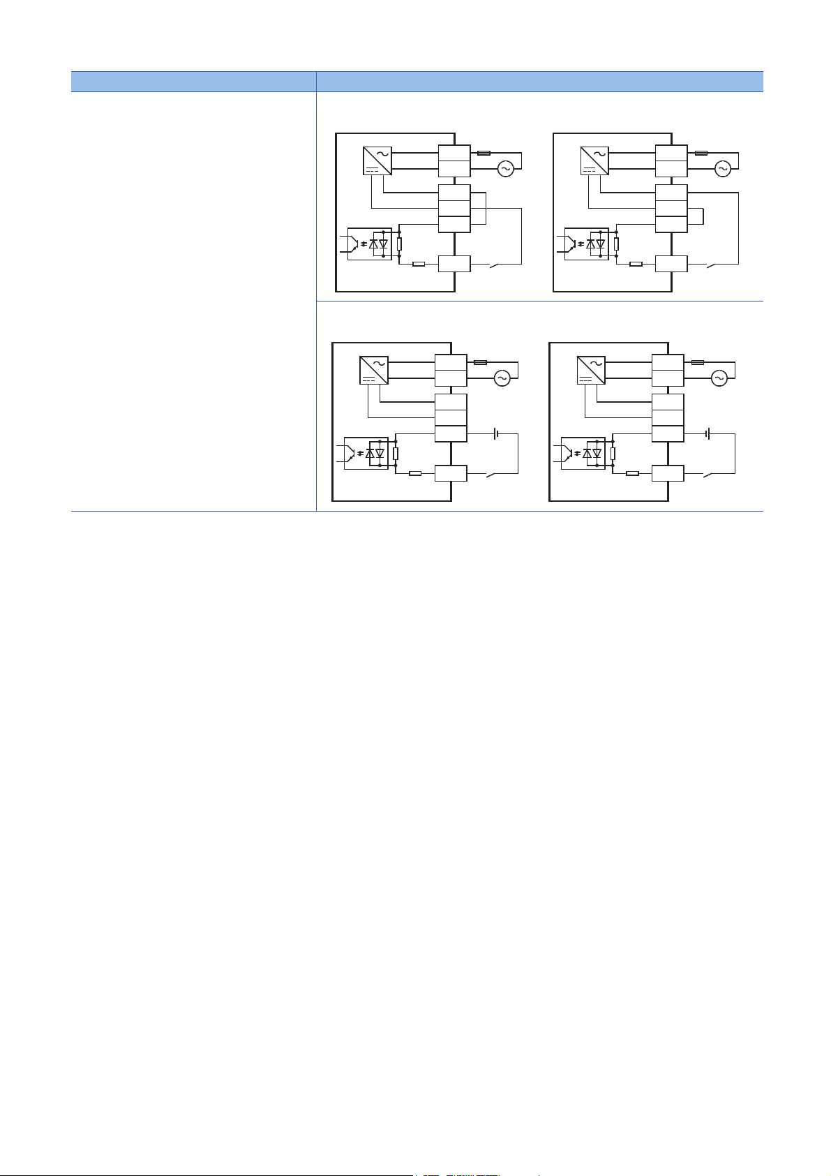
Item Specifications
Input circuit configuration • When using service power supply
Sink input wiring
Source input wiring
Fuse
L
N
100 to 240 V AC
24V
0V
S/S
X
• When using external power supply
Sink input wiring
Fuse
L
N
100 to 240 V AC
24V
0V
S/S
Input impedance Input impedance
X
Source input wiring
Fuse
L
N
100 to 240 V AC
24V
0V
S/S
Input impedanceInput impedance
X
Fuse
L
N
100 to 240 V AC
24V
0V
S/S
X
20
2 SPECIFICATIONS
2.3 Input Specifications
Page 23
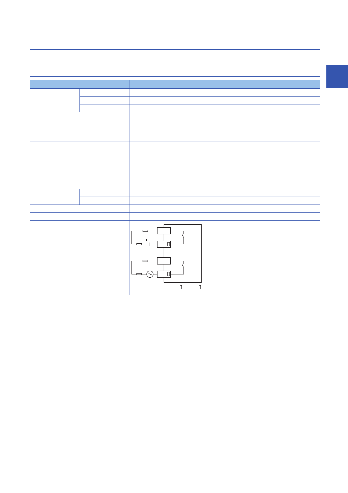
2.4 Output Specifications
The CPU module output specifications are explained below.
Relay output
Item Output Specifications
No. of output points FX5U-32MR/ 16 points
FX5U-64MR/ 32 points
FX5U-80MR/ 40 points
Connection type Removable terminal block (M3 screws)
Output type Relay
External power supply 30 V DC or less
240 V AC or less ("250 V AC or less" if not a CE, UL, cUL compliant item)
Max. load 2 A/point
Min. load 5 V DC, 2 mA (reference values)
Open circuit leakage current
Response time OFFON Approx. 10 ms
ONOFF Approx. 10 ms
Insulation of circuit Mechanical insulation
Indication of output operation LED is lit when output is on
Output circuit configuration
The total load current per common terminal should be the following value.
• 4 output points/common terminal: 8 A or less
• 8 output points/common terminal: 8 A or less
For details on the common, refer to Page 29 Interpretation of terminal block layout.
Load
DC power supply
Fuse
Load
AC power supply
Fuse
A number is entered in the of [COM ].
Y
COM
Y
COM
2
2 SPECIFICATIONS
2.4 Output Specifications
21
Page 24
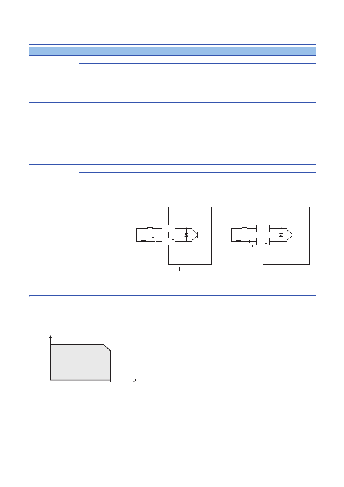
Transistor output
Simultaneous ON ratio
Derating curve
When service power supply or external power supply (24 V DC) is used for input circuits
100%
Ambient temperature
applicable
5550
80%
Item Output specifications
No. of output points FX5U-32MT/ 16 points
FX5U-64MT/ 32 points
FX5U-80MT/ 40 points
Connection type Removable terminal block (M3 screws)
Output type FX5U-MT/ES Transistor/sink output
FX5U-MT/ESS Transistor/source output
External power supply 5 to 30 V DC
Max. load 0.5 A/point
The total load current per common terminal should be the following value.
• 4 output points/common terminal: 0.8 A or less
• 8 output points/common terminal: 1.6 A or less
For details on the common, refer to Page 29 Interpretation of terminal block layout.
Open circuit leakage current 0.1 mA or less/30 V DC
Voltage drop when ON Y000 to Y003 1.0 V or less
Y004 and subsequent 1.5 V or less
Response time Y000 to Y003 2.5 s or less/10 mA or more (5 to 24 V DC)
Y004 and subsequent 0.2 ms or less/200 mA or more (24 V DC)
Insulation of circuit Photo-coupler insulation
Indication of output operation LED is lit when output is on
Output circuit configuration
Sink output wiring Source output wiring
Load
DC power supply
Fuse
A number is entered in the of [COM ].
Y
COM
Load
DC power supply
Fuse
A number is entered in the of [+V ].
Y
+V
2.5 Input/Output Derating Curve
The derating curve below shows the simultaneous ON ratio of available PLC inputs or outputs with respect to the ambient
temperature. Use the PLC within the simultaneous input or output ON ratio range shown in the figure.
2 SPECIFICATIONS
22
2.5 Input/Output Derating Curve
Page 25

2.6 Performance Specifications
Item Specification
Control system Stored-program repetitive operation
Input/output control system Refresh system
(Direct access input/output allowed by specification of direct access input/output [DX, DY])
Programming
specifications
Operation
specifications
Command
processing time
Memory
capacity
Flash memory (Flash ROM) write count Maximum 20000 times
File storage
capacity
Clock function Display data Year, month, day, hour, minute, second, day of week (leap year automatic detection)
No. of input/
output points
Power failure
*2
retention
*1 The value listed above indicates the number of files stored in the root folder.
*2 Clock data is retained using the power accumulated in a large-capacity capacitor incorporated into the PLC. When voltage of the large-
capacity capacitor drops, clock data is no longer accurately retained. The retention period of a fully charged capacitor (electricity is
conducted across the PLC for at least 30 minutes) is 10 days (ambient temperature: 25 (77)). How long the capacitor can hold the
data depends on the operating ambient temperature. When the operating ambient temperature is high, the holding period is short.
Programming language Ladder diagram (LD), structured text (ST), function block diagram/ladder diagram (FBD/LD)
Programming extension function Function block (FB), structured ladder, label programming (local/global)
Constant scan 0.2 to 2000 ms (can be set in 0.1 ms increments)
Fixed cycle interrupt 1 to 60000 ms (can be set in 1 ms increments)
Timer performance specifications 100 ms, 10 ms, 1 ms
No. of program executions 32
No. of FB files 16 (Up to 15 for user)
Execution type Standby type, initial execution type, scan execution type, event execution type
Interrupt type Internal timer interrupt, input interruption, high-speed comparison match interrupt
LD X0 34 ns
MOV D0 D1 34 ns
Program capacity 64 k steps
(128 kbytes, flash memory)
SD memory card Memory card capacity (SD/SDHC memory card: Max. 4 Gbytes)
Device/label memory 120 kbytes
Data memory/standard ROM 5 Mbytes
Device/label memory 1
Data memory
P: No. of program files
FB: No. of FB files
SD Memory Card 2 Gbytes: 511
Precision -2.96 to +3.74 (TYP.+1.42) s/d (Ambient temperature: 0 (32))
(1) No. of input/output points 256 points or less
(2) No. of remote I/O points 384 points or less
Total No. of points of (1) and (2) 512 points or less
Retention method Large-capacity capacitor
Retention time 10 days (Ambient temperature: 25 (77))
Data retained Clock data
P: 32, FB: 16
*1
4 Gbytes: 65534
-3.18 to +3.74 (TYP.+1.50) s/d (Ambient temperature: 25 (77))
-13.20 to +2.12 (TYP.-3.54) s/d (Ambient temperature: 55 (131))
*1
2
2 SPECIFICATIONS
2.6 Performance Specifications
23
Page 26

Number of device points
Item Base Max. number of points
No. of user device
points
No. of system device
points
Module access device Intelligent function module device 10 65536 points (designated by U\G)
No. of index register
points
No. of file register
points
No. of nesting points Nesting (N) 10 15 points (fixed)
No. of pointer points Pointer (P) 10 4096 points
Others Decimal
*1 Can be changed with parameters within the capacity range of the CPU built-in memory.
*2 Total of the index register (Z) and long index register (LZ) is maximum 24 words.
Input relay (X) 8 1024 points The total number of X and Y assigned to input/output points is up to
Output relay (Y) 8 1024 points
256 points.
Internal relay (M) 10 32768 points (can be changed with parameter)
Latch relay (L) 10 32768 points (can be changed with parameter)
Link relay (B) 16 32768 points (can be changed with parameter)
Annunciator (F) 10 32768 points (can be changed with parameter)
Link special relay (SB) 16 32768 points (can be changed with parameter)
Step relay (S) 10 4096 points (fixed)
Timer system Timer (T) 10 1024 points (can be changed with parameter)
Accumulation
timer system
Counter
system
Accumulation timer
10 1024 points (can be changed with parameter)
(ST)
Counter (C) 10 1024 points (can be changed with parameter)
Long counter (LC) 10 1024 points (can be changed with parameter)
Data register (D) 10 8000 points (can be changed with parameter)
Link register (W) 16 32768 points (can be changed with parameter)
Link special register (SW) 16 32768 points (can be changed with parameter)
Special relay (SM) 10 10000 points (fixed)
Special register (SD) 10 12000 points (fixed)
Index register (Z)
*2
Long index register (LZ)
*2
10 24 points
10 12 points
File register (R) 10 32768 points (can be changed with parameter)
Interrupt pointer (I) 10 178 points (fixed)
Signed 16 bits: -32768 to +32767, 32 bits: -2147483648 to +2147483647
constant (K)
Unsigned 16 bits: 0 to 65535, 32 bits: 0 to 4294967295
Hexadecimal constant (H) 16 bits: 0 to FFFF, 32 bits: 0 to FFFFFFFF
Real constant
Single precision E-3.40282347+38 to E-1.17549435-38, 0, E1.17549435-38 to E3.40282347+38
(E)
Character string Shift-JIS code max. 255 single-byte characters (256 including NULL)
*1
*1
*1
*1
*1
*1
*1
*1
*1
*1
*1
*1
*1
24
2 SPECIFICATIONS
2.6 Performance Specifications
Page 27

2.7 Built-in Analog Specifications
The analog input/output specifications of the built-in analog function are explained below.
For details on the analog built-in function, refer to MELSEC iQ-F FX5 User's Manual (Analog Control).
Analog input
Item Specifications
Analog input points 2 points (2 channels)
Analog input Voltage 0 to 10 V DC (input resistance 115.7 k)
Digital output Unsigned 12-bit binary
I/O characteristics, Maximum resolution Digital output value 0 to 4000
Maximum resolution 2.5 mV
*1
Accuracy
(Accuracy in respect to maximum digital
output value)
Conversion speed 30 s /channels (data refreshed every operation cycle)
Absolute maximum input -0.5 V, +15 V
Insulation method Inside the PLC and the analog input circuit are not insulated. Between input terminals
Occupied points 0 points (does not pertain to the max. No. of input/output points of the PLC.)
Terminal block used European-type terminal block
Ambient temperature
25 5 (77 41)
Ambient temperature
0 to 55 (32 to 131)
Within 0.5% (20 digit
Within 1.0% (40 digit
(channels) is not insulated.
)
*1
)
*1 "Digit" refers to digital values.
Analog output
Item Specifications
Analog output points 1 points (1 channels)
Digital input Unsigned 12-bit binary
Analog output Voltage 0 to 10 V DC (external load resistance 2 k to 1 M)
*1
I/O characteristics, Maximum resolution
*2
Accuracy
(Accuracy in respect to maximum analog
output value)
Conversion speed 30 s (data refreshed every operation cycle)
Insulation method Inside the PLC and the analog output circuit are not insulated.
Occupied points 0 points (does not pertain to the max. No. of input/output points of the PLC.)
Terminal block used European-type terminal block
*1 There is a dead band near 0 V output, which is an area where some analog output values do not reflect digital input values.
*2 External load resistance is set to 2 k when shipped from the factory. Thus, output voltage will increase somewhat if the resistance is
set higher than 2 k. When the resistance is 1 M, output voltage increases maximum 2%.
*3 "Digit" refers to digital values.
Digital input value 0 to 4000
Maximum resolution 2.5 mV
Ambient temperature
25 5 (77 41)
Ambient temperature
0 to 55 (32 to 131)
Within 0.5% (20 digit
Within 1.0% (40 digit
*3
)
*3
)
2
2 SPECIFICATIONS
2.7 Built-in Analog Specifications
25
Page 28

2.8 Communication Specifications
The built-in Ethernet and built-in RS-485 communication specifications are as explained below.
Built-in Ethernet communication
For details of built-in Ethernet communication, refer to the following.
MELSEC iQ-F FX5 User's Manual (Ethernet Communication)
MELSEC iQ-F FX5 User's Manual (SLMP)
Item Specifications
Data transmission speed 100/10 Mbps
Communication mode Full-duplex (FDX) / Half-duplex (HDX)
Interface RJ45 connector
Transmission method Base band
Maximum segment length (The distance between hub and node) 100 m (328'1")
Cascade connection 100BASE-TX Cascade connection max. 2 stages
10BASE-T Cascade connection max. 4 stages
Protocol type MELSOFT connection
SLMP (3E frame)
Socket communication
Predefined protocol support
Number of simultaneously open connections allowed Total of 8 for socket communication, MELSOFT connection, SLMP, and Predefined
Insulation method Pulse transformer insulation
Cable used
*2
For 100BASE-TX connection Ethernet standard-compatible cable, category 5 or higher (STP cable)
For 10BASE-T connection Ethernet standard-compatible cable, category 3 or higher (STP cable)
protocol support
(Up to 8 external devices can access one CPU module at the same time.)
*1
*1
*1 Number of stages that can be connected when a repeater hub is used. When a switching hub is used, check the specifications of the
switching hub used.
*2 A straight cable can be used. If a personal computer or GOT and CPU module are directly connected a cross cable can be used.
Built-in RS-485 communication
For details of built-in RS-485 communication, refer to the following.
MELSEC iQ-F FX5 User's Manual (Serial Communication)
MELSEC iQ-F FX5 User's Manual (MODBUS Communication)
Item Specifications
Transmission standards Conforms to RS-485/RS-422 specifications
Data transmission speed Max. 115.2 kbps
Communication method Full-duplex (FDX) / Half-duplex (HDX)
Maximum total extension distance 50 m (164'0")
Protocol type MELSOFT connection
Non-protocol communication
MELSEC Communication protocol (3C/4C frames)
MODBUS RTU
Predefined protocol support
Inverter communication
N:N network
Insulation method Not insulated
Terminal resistors Built-in (OPEN/110 /330 )
Terminal block used European-type terminal block
26
2 SPECIFICATIONS
2.8 Communication Specifications
Page 29
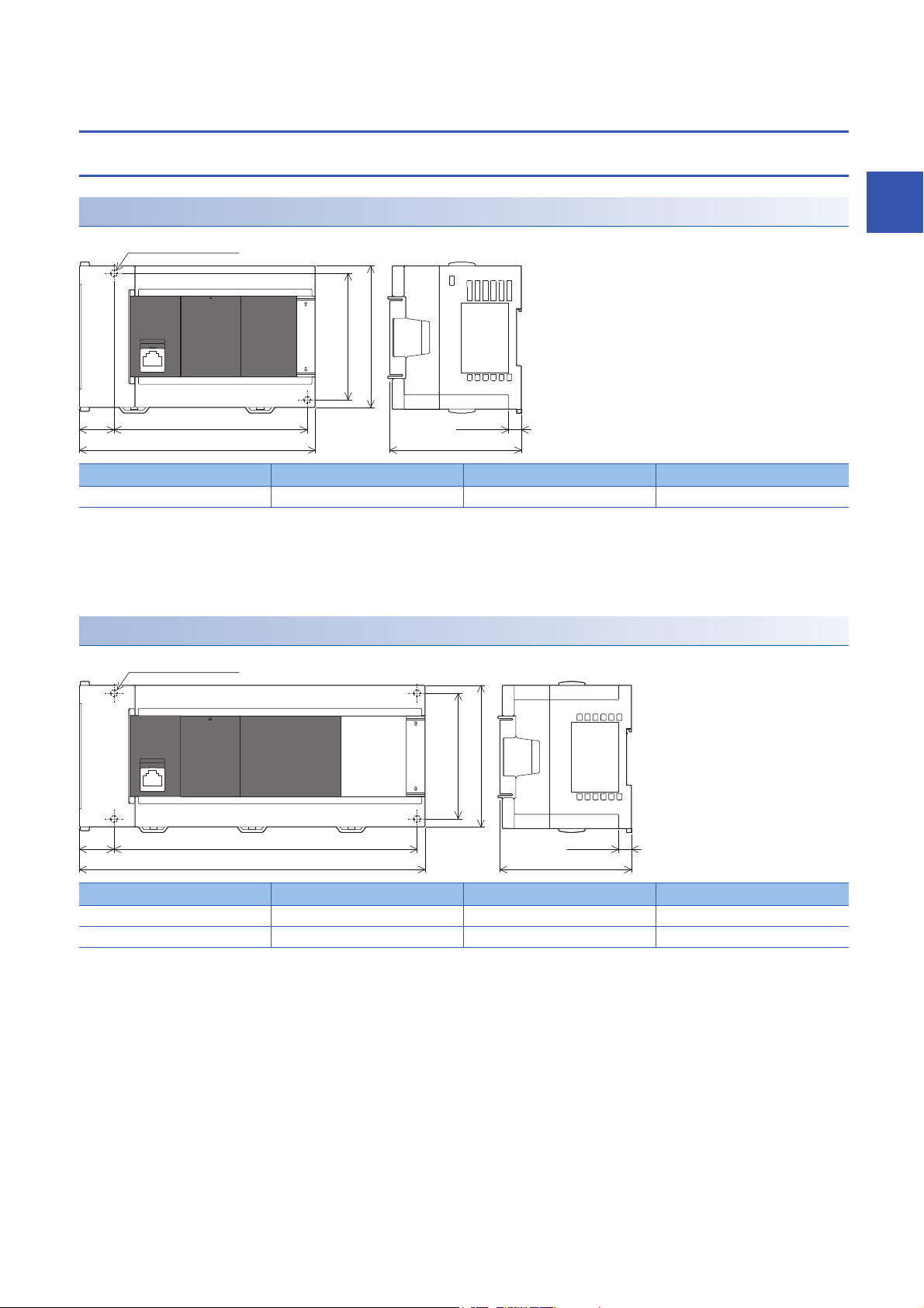
2.9 External Dimensions
W122
(0.87")
80 (3.15")
(mounting hole pitch)
90 (3.55")
W
83 (3.27")
Unit: mm (inches)
8 (0.32")
2-4.5 mounting holes
W122
(0.87")
80 (3.15")
(mounting hole pitch)
90 (3.55")
W
83 (3.27")
8 (0.32")
4-4.5 mounting holes
Unit: mm (inches)
CPU module
FX5U-32M
Model W W1 (mounting hole pitch) Mass (weight)
FX5U-32M 150 mm (5.91") 123 mm (4.85") Approx. 0.65 kg (1.43 lbs)
• Exterior color
Main body: Munsell 0.6B7.6/0.2
• Accessories
Dust proof protection sheet
Manual supplied with product
FX5U-64M, FX5U-80M
2
Model W W1 (mounting hole pitch) Mass (weight)
FX5U-64M 220 mm (8.67") 193 mm (7.6") Approx. 1.0 kg (2.2 lbs)
FX5U-80M 285 mm (11.23") 258 mm (10.16") Approx. 1.2 kg (2.64 lbs)
• Exterior color
Main body: Munsell 0.6B7.6/0.2
• Accessories
Dust proof protection sheet
Manual supplied with product
2.9 External Dimensions
2 SPECIFICATIONS
27
Page 30
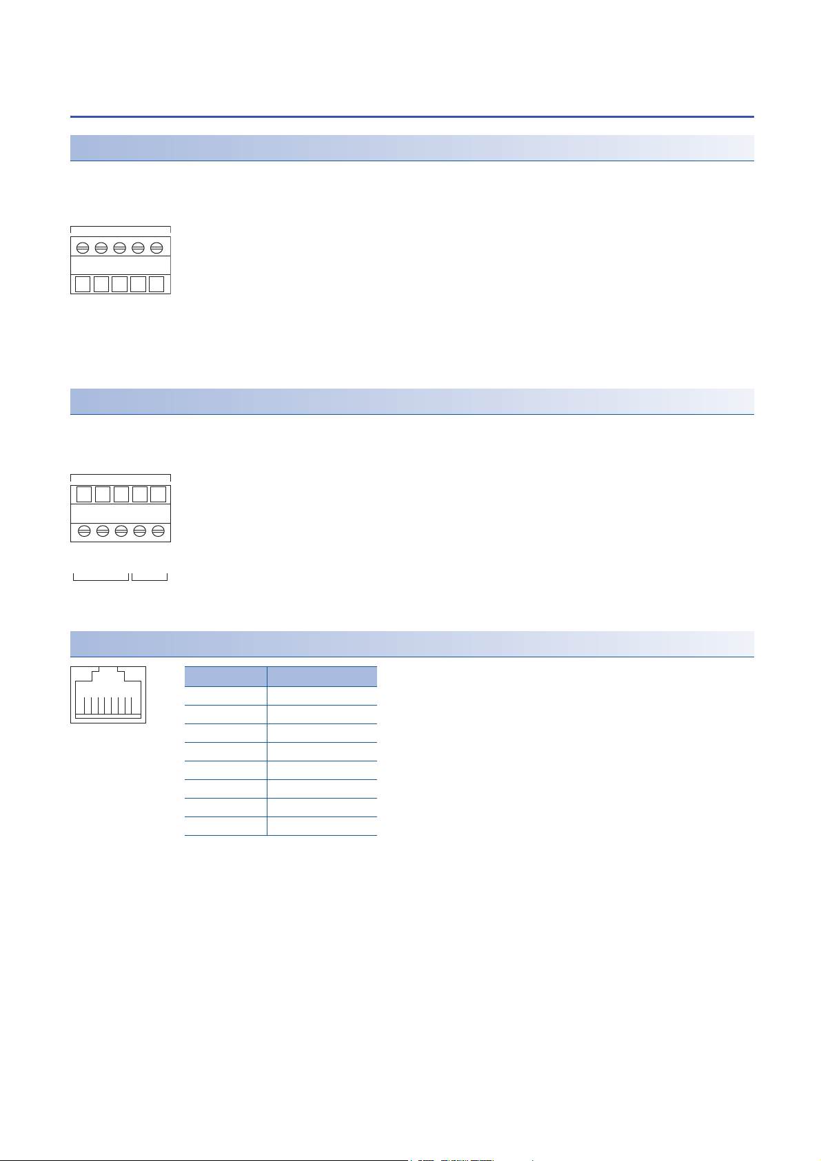
2.10 Terminal Layout
5 poles
RDB (RXD-)
SDA (TXD+)
SDB (TXD-)
SG (GND)
European type
terminal block
5 poles
V-
V+
V-
V2+
V1+
European type
terminal block
Analog
input
Analog
output
81
Pin
1
2
3
4
5
6
7
8
Signal name
TD+
TD-
RD+
Not used
Not used
RD-
Not used
Not used
Built-in RS-485 terminal
Built-in analog terminal
Built-in Ethernet connector
28
2 SPECIFICATIONS
2.10 Terminal Layout
Page 31

Power, input/output terminal block
X0S/S 0 V
24 V
N
L1
234567X10111213141516
17
FX5U-32MR/ES
Input terminal
Output terminal
Partition
[•] Vacant terminal (Do not use)
Output terminals
connected to COM3
Y42
3
COM1
1
Y0
COM0
567
Y10111213Y141516
17
COM2 COM3
Common terminal
(4 points/common)
24 V DC service
power supply
Power supply
terminals
Y42
3 +V11
Y0
+V0 567
Y101112
13
Y141516
17+V2 +V3
FX5U-32MT/ESS
X0S/S 0V
24VNL1
234567X10111213141516
17
Y42
3
COM1
1
Y0
COM0
567
Y101112
13
Y141516
17
COM2 COM3
FX5U-32MR/ES, FX5U-32MT/ES
FX5U-64MT/ESS
0VS/S 0V
24VNL 24VX01234567
X1011121314 2216 X20
2115 17 2324252627
X30313233343536
37
Y42
3
COM1
1
Y0
COM0
567
Y101112
13
Y141516
17
COM2 COM3
2422Y20
21 23
COM4
252627
32Y30
333435
COM5
36
31 37
Y42
3 +V11
Y0
+V0 567
Y101112
13
Y141516
17+V2 +V3
2422Y20
21 23+V4 252627
32Y30
333435
+V536
31 37
FX5U-64MR/ES, FX5U-64MT/ES
■Interpretation of terminal block layout
• Indication of power supply terminals
[L] and [N] terminals.
For external wiring, refer to Page 79 Power Supply Wiring.
• Indication of 24 V DC service power supply
[0V] and [24V] terminals.
• Indication of input terminal
For external wiring, refer to Page 83 Input Wiring.
• Indication of output terminals connected to common (COM)
One common terminal covers 4 or 8 output points.
The output number (Y) connected to common is the range inside the thick "separation line."
For transistor output (source) type, the "COM" terminal is the "+V" terminal.
2
■ FX5U-32M
■FX5U-64M
2 SPECIFICATIONS
2.10 Terminal Layout
29
Page 32

■FX5U-80M
FX5U-80MT/ESS
0VS/S 0V
24VNL 24VX01234567
X1011121314 2216 X20
2115 17 2324252627
X30313233343536 X40 42 44 46
37
Y42
3
COM1
1
Y0
COM0
567
Y101112
13
Y141516
17
COM2 COM3
2422Y20
21 23
COM4 COM5
25
26
27
32Y30
333435
36
31 37
Y40
COM6
41
42
41
43
44
43
45
46
454747
Y42
3
+V1
1
Y0
+V0
567
Y101112
13
Y141516
17
+V2 +V3
2422Y20
21 23
+V4 +V5
25
26
27
32Y30
333435
36
31 37
Y40
+V6
4241444346
45 47
FX5U-80MR/ES, FX5U-80MT/ES
2 SPECIFICATIONS
30
2.10 Terminal Layout
Page 33

3 PRODUCT LIST
I/O module
Input Output
•
FX5-8EX/ES
•
FX5-16EX/ES
Powered
input/output module
•
FX5-32ER/ES
•
FX5-32ET/ES
•
FX5-32ET/ESS
• FX5-8EYR/ES
• FX5-8EYT/ES
• FX5-8EYT/ESS
• FX5-16EYR/ES
• FX5-16EYT/ES
• FX5-16EYT/ESS
• FX5-4AD-ADP
• FX5-4DA-ADP
Analog
• FX5-232ADP
• FX5-485ADP
Communication
• FX5-232-BD
• FX5-485-BD
• FX5-422-BD-GOT
Battery
FX3U-32BL
CPU module
• FX5U-32MR/ES
• FX5U-32MT/ES
• FX5U-32MT/ESS
• FX5U-64MR/ES
• FX5U-64MT/ES
• FX5U-64MT/ESS
• FX5U-80MR/ES
• FX5U-80MT/ES
• FX5U-80MT/ESS
Input/output
FX5-CNV-BUS
Expansion boards
Intelligent function module
FX5-40SSC-S
FX5 extension power supply module
FX5-1PSU-5V
FX3 extension power supply module
FX3U-1PSU-5V
• FX3U-16CCL-M
• FX3U-64CCL
• FX3U-128ASL-M
Remote I/O
FX3 Intelligent function module
Analog
• FX3U-4AD
• FX3U-4DA
• FX3U-4LC
Network
Positioning
Bus
conversion
module
FX3U-1PG
High-speed counters
FX3U-2HC
Expansion
adapters
The following shows the system configuration equipment of the FX5U.
3.1 Overall Configuration
3
3 PRODUCT LIST
3.1 Overall Configuration
31
Page 34

3.2 CPU Module
FX5U
M
Power supply, Input/output type: Connection on terminal block.
• T/ES: AC power supply/24 V DC (sink/source) input/Transistor (sink) output
• R/ES: AC power supply/24 V DC (sink/source) input/Relay output
CPU module
• T/ESS: AC power supply/24 V DC (sink/source) input/Transistor (source) output
Total number of
input/output points
Model name
(abbreviation)
The CPU module incorporates a CPU, memory, input/output terminals, and power supply.
AC power supply common to 24 V DC sink and source input
Model No. of input/output points Input type Output type Connection
Total No.
of points
FX5U-32MR/ES 32 points 16 points 16 points 24 V DC
FX5U-32MT/ES Transistor
FX5U-32MT/ESS Transistor
FX5U-64MR/ES 64 points 32 points 32 points 24 V DC
FX5U-64MT/ES Transistor
FX5U-64MT/ESS Transistor
FX5U-80MR/ES 80 points 40 points 40 points 24 V DC
FX5U-80MT/ES Transistor
FX5U-80MT/ESS Transistor
*1 Power supply capacity when external power supply is used for input circuit
No. of
input
points
No. of
output
points
Relay Terminal block 900 mA 400 mA
(Sink/source)
(sink)
(source)
Relay Terminal block 1100 mA 600 mA
(Sink/source)
(sink)
(source)
Relay Terminal block 1100 mA 600 mA
(Sink/source)
(sink)
(source)
type
The model name of the CPU module can be checked on the nameplate on the right side. However, when
extension modules are connected, the nameplate cannot be seen. Check the model name in the following
places.
Power supply capacity
5 V DC power
supply
24 V DC
service
power supply
(480 mA
(740 mA
(770 mA
*1
)
*1
)
*1
)
32
3 PRODUCT LIST
3.2 CPU Module
Page 35

3.3 I/O Module
FX5 E
Input/output type
• X/ES: 24 V DC (sink/source) input
• YR/ES: Relay output
• YT/ES: Transistor (sink) output
• YT/ESS: Transistor (source) output
• R/ES: 24 V DC (sink/source) input/relay output
• T/ES: 24 V DC (sink/source) input/transistor (sink) output
• T/ESS: 24 V DC (sink/source) input/transistor (source) output
Input/output extension
Total number of
input/output points
The I/O module is used to expand inputs/outputs.
For details, refer to Page 132 I/O Module.
Input module
The input module is used to expand inputs.
Model No. of input/output points Input type Output
Total No.
of points
FX5-8EX/ES 8 points 8 points 24 V DC
FX5-16EX/ES 16 points 16 points 100 mA 85 mA
No. of
input
points
No. of
output
points
(Sink/source)
type
Terminal block 75 mA 50 mA
Connection
type
Current consumption
5 V DC power
supply
24 V DC
power supply
3
Output module
The output module is used to expand outputs.
Model No. of input/output points Input type Output
Total No.
of points
FX5-8EYR/ES 8 points 8 points Relay Terminal block 75 mA 75 mA
FX5-8EYT/ES Transistor
FX5-8EYT/ESS Transistor
FX5-16EYR/ES 16 points 16 points Relay Terminal block 100 mA 125 mA
FX5-16EYT/ES Transistor
FX5-16EYT/ESS Transistor
No. of
input
points
No. of
output
points
type
(sink)
(source)
(sink)
(source)
Connection
type
Current consumption
5 V DC power
supply
24 V DC
power supply
Powered input/output module
The powered input/output module includes a power supply and is used to expand input/output.
Model No. of input/output points Input type Output
Total No.
of points
FX5-32ER/ES 32 points 16 points 16 points 24 V DC
FX5-32ET/ES Transistor
FX5-32ET/ESS Transistor
No. of
input
points
No. of
output
points
(Sink/source)
type
Relay Terminal block 965 mA 250 mA
(sink)
(source)
Connection
type
Power supply capacity
5 V DC power
supply
24 V DC
service power
supply
(310 mA
*1
)
*1 Power supply capacity when external power supply is used for input circuit
3 PRODUCT LIST
3.3 I/O Module
33
Page 36

3.4 Intelligent Function Module
Intelligent function modules are modules that have functions other than input/output, such as simple motion modules.
For details, refer to manuals of each module.
FX5 intelligent Function Module
Positioning
Model Function No. of occupied
input/output
points
FX5-40SSC-S 4-axis control (compatible with SSCNET /H) 8 points 250 mA
Current consumption
5 V DC power
supply
24 V DC
power supply
External 24 V DC
power supply
FX3 intelligent Function Module
The following FX3 intelligent functions modules can be used in FX5U CPU module systems by using bus conversion modules.
For the bus conversion modules to be connected, refer to Page 36 Bus Conversion Module.
To use the modules, refer to Page 40 Bus conversion module.
Analog
Model Function No. of occupied
input/output
points
FX3U-4AD 4-ch voltage/current input 8 points 110 mA 90 mA
FX3U-4DA 4-ch voltage/current output 120 mA 160 mA
FX3U-4LC 4-ch temperature control (resistance
thermometer/thermocouple/low voltage)
4 transistor output points
Positioning
Current consumption
5 V DC power
supply
160 mA 50 mA
24 V DC
power supply
External 24 V DC
power supply
Model Function No. of occupied
input/output
points
FX3U-1PG Pulse output for independent 1-axis control 8 points 150 mA 40 mA
Current consumption
5 V DC power
supply
24 V DC
power supply
External 24 V DC
power supply
High-speed counter
Model Function No. of occupied
input/output
points
FX3U-2HC 2-ch high-speed counter 8 points 245 mA
Current consumption
5 V DC power supply 24 V DC power supply
34
3 PRODUCT LIST
3.4 Intelligent Function Module
Page 37

Network
Model Function No. of occupied
input/output
points
FX3U-16CCL-M
FX3U-64CCL
FX3U-128ASL-M
*1 GX Works3 does not support this module. When using this module, perform setting via buffer memory.
*2 Number of remote I/O points is added.
For details, refer to Page 46 Calculation of number of remote I/O points.
*3 The number of input/output points set by the rotary switch is added. For details, refer to FX3U-128ASL-M User's Manual.
*4 This value does not include supply current to slave modules. For details, refer to FX3U-128ASL-M User's Manual.
*5 Note that the warranty for this model differs from the ones for other PLCs. For details, refer to FX3U-128ASL-M User's Manual.
*1
Master for CC-Link (compatible with Ver. 2.00
and Ver. 1.10)
*1
Intelligent device station for CC-Link 8 points 220 mA
*1*5
Master for AnyWireASLINK 8 points
8 points
*2
*3
Current consumption
5 V DC power
supply
240 mA
130 mA 100 mA
24 V DC
power supply
External 24 V DC
power supply
*4
3.5 Expansion Board
The expansion board is to expand functions and is connected to the front face of the CPU module.
For details on the specifications of the expansion board, refer to Hardware manuals of each product.
Model Function No. of occupied
input/output points
FX5-232-BD For RS-232C communication 20 mA
FX5-485-BD For RS-485 communication 20 mA
FX5-422-BD-GOT For RS-422 communication (For
GOT connection)
20 mA
Current consumption
5 V DC power supply 24 V DC power supply
*1
3
*1 When the GOT 5 V type is connected with this product, the current consumption increases.
For the current consumption, refer to the manual of the model to be connected.
3.6 Expansion Adapter
The expansion adapter is to expand functions and is connected on the left side of the CPU module.
For details on the specifications of the expansion adapter, refer to Hardware manuals of each product.
Model Function No. of occupied
input/output points
FX5-4AD-ADP 4-ch voltage input/current input 10 mA 20 mA
FX5-4DA-ADP 4-ch voltage output/current output 10 mA 160 mA
FX5-232ADP For RS-232C communication 30 mA 30 mA
FX5-485ADP For RS-485 communication 20 mA 30 mA
Current consumption
5 V DC power
supply
24 V DC power
supply
External 24 V DC
power supply
3 PRODUCT LIST
3.5 Expansion Board
35
Page 38

3.7 Extension Power Supply Module
The extension power supply module is an added power supply if the built-in power supply of the CPU module is insufficient.
For details on the specifications of the extension power supply module, refer to Manuals of each product.
FX5 expansion power supply module
Model Function No. of occupied
input/output points
FX5-1PSU-5V Extension power supply 1200 mA
Power supply capacity
5 V DC power supply 24 V DC power supply
*1
300 mA
*1
FX3 expansion power supply module
With FX5U systems, the following FX3 extension power supply module can be used.
However, a bus conversion module is required to use the intelligent function modules.
For details, refer to Page 40 Bus conversion module.
Model Function No. of occupied
input/output points
FX3U-1PSU-5V Extension power supply 1000 mA
*1 If the ambient temperature exceeds 40, use the extension power supply module at the following current values within the derating
range.
Derating curve
FX5-1PSU-5V FX3U-1PSU-5V
Output current [mA]
1200
800
24 V DC
300
200
5 V DC
Ambient
temperature []
5540
Output current [mA]
1000
800
24 V DC
300
200
Power supply capacity
5 V DC power supply 24 V DC power supply
*1
300 mA
*1
5 V DC
Ambient
temperature []
5540
3.8 Bus Conversion Module
The bus conversion module is to connect FX3 extension modules with FX5U CPU module systems. For details on the
specifications of the bus conversion module, refer to MELSEC iQ-F FX5-CNV-BUS Hardware Manual.
Model Function No. of occupied
input/output points
FX5-CNV-BUS Bus conversion from FX5
extension modules or FX5
intelligent function modules
8 points 150 mA
Current consumption
5 V DC power supply 24 V DC power supply
3.9 SD Memory Card
For details on the SD memory card, refer to Page 141 SD Memory Card.
Model Function
NZ1MEM-2GBSD SD memory card (Mitsubishi product)
NZ1MEM-4GBSD
L1MEM-2GBSD
L1MEM-4GBSD
36
3 PRODUCT LIST
3.7 Extension Power Supply Module
Page 39

3.10 Battery
For details on the battery, refer to Page 116 Battery.
Model Function
FX3U-32BL Battery
3.11 Communication Cable
Use a communication cable to connect a PLC with a personal computer by RS-232C communication.
Model Function
FX-232CAB-1 FX5-232ADPPersonal computer
FX5-232-BDPersonal computer
3.12 Engineering Tool
For design and programming of FX5U CPU module systems, use GX Works3.
For the operation method, refer to GX Works3 Operating Manual.
Model Function
GX Works3 MELSEC PLC software package
3
3 PRODUCT LIST
3.10 Battery
37
Page 40

4 SYSTEM CONFIGURATION
Ex.
Intelligent module
FX3U-1PSU-5V FX3U-16CCL-M
Module No.5
FX3U-4DA
Module No.4
FX3U-4AD
Module No.3
FX3 extension module
When CC-Link is used
FX5 extension module
FX3 extension module
X000 to X017
FX5U-32MR/ES
CPU module
Y000 to Y017
Expansion board
Configuration of whole system
Expansion board and expansion adapters
Remote I/O Remote I/O
Bus
conversion
module
FX3 extension power supply module
Intelligent
module
Intelligent
module
Intelligent
module
Range of devices powered by FX3 extension power supply module
Expansion
adapters
FX5-40SSC-S
Module No.1
FX5-1PSU-5V
I/O module
-
Y020 to Y037
FX5-16EYR/ES
X020 to X037
-
FX5-16EX/ES
Simple motion
module
FX5-CNV-BUS
Module No.2
FX5 extension power
supply module
Output
module
Input
module
Range of devices powered
by FX5 extension power
supply module
Range of devices powered
by CPU module
Configuration of a whole system
The configuration of an entire system is shown below as an example.
For assignment of the module numbers for extension modules, refer to Page 62 Module number of Extension modules.
38
4 SYSTEM CONFIGURATION
Page 41

4.1 Rules of System Configuration
Ex.
CPU module
Up to 16 modules
*1
Up to 12 modules
Up to 10 modules
Up to 8 modules
Up to 2 modules
Expansion
adapters
(Commu-
nication)
Expansion
board
Input
module,
Output
module
Input
module,
Output
module
FX5
Intelligent
module
FX5
Intelligent
module
FX3
Intelligent
module
FX3
Intelligent
module
FX5
extension
power
supply
module
FX3
extension
power
supply
module
Bus
conversion
module
Up to 2
modules
Expansion
adapters
(Analog)
Up to 4
modules
Up to 1
module
Up to 1
module
Up to 8
modules
Up to 8 modules
Up to 256 points
CPU module I/O module
• Expansion board
• Expansion adapter
• CC-Link master
• AnyWireASLINK master
CC-Link/AnyWireASLINK system
Up to 384 points
Number of input/output points on whole system Up to 512 points
1. Number of input/output points
(including input/output occupied points)
Remote I/O station Remote I/O station Remote I/O station Remote I/O station
2. Number of remote input/output points for
CC-Link/AnyWireASLINK
FX5
Intelligent
module
FX5
Intelligent
module
Bus
conversion
module
The system configuration must meet the following four requirements.
Number of connected extension device
The number of extension devices that can be connected to a single system of FX5U CPU module is limited.
For details, refer to Page 41 Limitations on the Number of Connected Extension Devices.
*1 Extension power supply modules are not included in the number of connected devices.
4
Number of input/output points
With the FX5U CPU module, a total of 512 points or less including the number of input/output points of extension devices
(max. 256 points) and number of remote I/O points (max. 384 points) can be controlled.
For details on the number of input/output points, refer to Page 45 Limitation on the Number of Input/Output Points.
4 SYSTEM CONFIGURATION
4.1 Rules of System Configuration
39
Page 42

Current consumption
Power supply from CPU module
*1
Power supply from
FX5 extension power supply module
*1
Power supply from
powered input/output module
*1
CPU module
Expansion
adapters
Expansion
board
FX5
Intelligent
module
FX5
Intelligent
module
FX5
Intelligent
module
FX3
Intelligent
module
FX5
extension
power
supply
module
Bus
conversion
module
Input
module,
Output
module
Input
module,
Output
module
Input
module,
Output
module
Powered
input/
output
module
Power of extension devices is supplied from the CPU module or extension power supply module.
The number of extension devices that can be connected must be determined from the capacity of the power supply.
For details on the current consumption, refer to Page 48 Limitation on Current Consumption.
*1 Power is supplied to input circuit of input modules by service power supply or external power supply.
Limitations when using FX3 extension devices
■Bus conversion module
• A bus conversion module is required to use FX3 extension module. FX3 extension module can be connected to the right
side of the bus conversion module only.
• For limitation on the number of connectable modules, refer to Page 44 Connection to the bus conversion module
(connection with FX3 extension devices).
■Limitations on intelligent function modules
Note that some FX3 intelligent function modules have limitations on the number of modules and order in which they are added
for each individual module.
Model Limitations
FX3U-2HC Up to two modules connectable per system.
When FX5-1PSU-5V is not used, connect immediately after the bus conversion module.
FX3U-16CCL-M Only one module may be connected per system.
FX3U-64CCL Only one module may be connected per system.
FX3U-128ASL-M Only one module may be connected per system.
40
4 SYSTEM CONFIGURATION
4.1 Rules of System Configuration
Page 43

4.2 Limitations on the Number of Connected
Expansion board
Communication
adapter
Analog adapter
FX5-232ADP FX5-485ADP
Up to 2 modules
FX5-4AD-ADP FX5-4DA-ADP
Up to 4 modules
Extension Devices
Number of connected expansion boards
Only 1 expansion board can be connected on the front face of the CPU module.
Number of connected expansion adapters
There is a limitation on the number of expansion adapter connected to the CPU module as follows.
Type Limitations
Communication adapter Up to 2 modules can be connected.
Analog adapter Up to 4
modules can be connected.
4
4.2 Limitations on the Number of Connected Extension Devices
4 SYSTEM CONFIGURATION
41
Page 44

Number of connected extension modules
• • • • • • • • • • • •
Up to 16 modules (excluding extension power supply module)
Up to 1 module
Up to 2 modules
CPU module
I/O
module
I/O
module
Extension
power
supply
module
Extension
power
supply
module
Bus
conversion
module
Up to 12 modules
Up to 8
modules
CPU module
FX5
Intelligent
module
FX5
Intelligent
module
Powered input/
output module,
FX5 extension
power supply
module
Input
module,
Output
module
Input
module,
Output
module
Up to 12 modules
CPU module
FX3
Intelligent
module
Up to 8 modules
Intelligent
module
FX3
Intelligent
module
Bus
conversion
module
Input
module,
Output
module
FX3 extension
power supply
module
Overall system limitation
There is a limitation on the number of connected extension modules in a whole system as follows.
Type Limitations
Extension module Up to 16 modules can be connected to a system.
(Extension power supply modules are excluded.)
Extension power supply module Up to 2 modules
Bus conversion module Only 1 module
Connection to the CPU module
There is a limitation on the number of extension modules connected to the CPU module as follows.
The number of extension modules added from the right side of the CPU module to powered input/output module or the
extension power supply module must be as follows.
Type Limitations
Total No. of input modules, output modules, intelligent function modules, and bus
conversion modules
Total No. of intelligent function module and bus conversion modules Up to 8 modules
can be connected to a system.
can be connected to a system.
Up to 12 modules can be connected.
can be connected.
42
4 SYSTEM CONFIGURATION
4.2 Limitations on the Number of Connected Extension Devices
Page 45

Connection to the powered input/output module
Up to 10 modules
Up to 8
modules
Powered
input/output
module
FX5
Intelligent
module
FX5
Intelligent
module
Powered input/
output module,
FX5 extension
power supply
module
Input
module,
Output
module
Input
module,
Output
module
Up to 8 modules
Up to 10 modules
FX5
Intelligent
module
FX3
Intelligent
module
FX3
Intelligent
module
Powered
input/output
module
Bus
conversion
module
Input
module,
Output
module
FX3 extension
power supply
module
Up to 10 modules
Up to 8
modules
FX5 extension
power supply
module
FX5
Intelligent
module
FX5
Intelligent
module
Powered input/
output module,
FX5 extension
power supply
module
Input
module,
Output
module
Input
module,
Output
module
Up to 8 modules
Up to 10 modules
FX5
Intelligent
module
FX3
Intelligent
module
FX3
Intelligent
module
Bus
conversion
module
Input
module,
Output
module
FX3 extension
power supply
module
FX5 extension
power supply
module
There is a limitation on the number of extension modules connected to the powered input/output module as follows.
The number of connected modules from the right side of the powered input/output module the next extension power supply
module added later must be as follows.
Type Limitations
Total No. of input module, output module intelligent function modules, and bus
conversion modules
Total No. of intelligent function module and bus conversion modules Up to 8 modules
Up to 10 modules can be connected.
can be connected.
4
Connection to the FX5 extension power supply module (FX5-1PSU-5V)
There is a limitation on the number of extension modules connected to the FX5 extension power supply module as follows.
The number of connected modules from the right side of the FX5 extension power supply module to powered input/output
module or the next extension power supply module added later must be as follows.
Type Limitations
Total No. of input modules, output modules, intelligent function modules, and bus
conversion modules
Total No. of intelligent function module and bus conversion modules Up to 8 modules
Up to 10 modules can be connected.
can be connected.
4 SYSTEM CONFIGURATION
4.2 Limitations on the Number of Connected Extension Devices
43
Page 46

Connection to the bus conversion module (connection with FX3 extension devices)
Precautions
Up to 8 modules
• • • • •
FX3
Intelligent
module
FX3
extension
power
supply
module
Bus
conversion
module
Up to 6 modules
• • • • •
FX3
Intelligent
module
Bus
conversion
module
There is a limitation on the number of extension modules connected to the bus conversion module as follows.
The number of modules connected on the right side of the bus conversion module must be as follows.
■When using FX3 extension power supply modules
Type Limitations
Total No. of intelligent function modules Up to 8 modules can be connected.
■When not using FX3 extension power supply modules
Type Limitations
Total No. of intelligent function modules Up to 6 modules can be connected.
FX5 extension modules cannot be connected on the right side of the bus conversion module.
44
4 SYSTEM CONFIGURATION
4.2 Limitations on the Number of Connected Extension Devices
Page 47

4.3 Limitation on the Number of Input/Output Points
Up to 256 points
CPU module I/O module
• Expansion board
• Expansion adapter
• CC-Link master
• AnyWireASLINK master
CC-Link/AnyWireASLINK system
Up to 384 points
Number of input/output points on whole system Up to 512 points
1. Number of input/output points
(including input/output occupied points)
Remote I/O station Remote I/O station Remote I/O station Remote I/O station
2. Number of remote input/output points for
CC-Link/AnyWireASLINK
FX5
Intelligent
module
FX5
Intelligent
module
Bus
conversion
module
≥
512 points
+
Number of remote I/O points
(2) points
Number of input/output points
(1) points
Maximum number of
points controllable on
system
The total number of inputs and
outputs which is obtained in the
next subsection.
The total number of remote I/O
which is obtained in the next
subsection.
Number of input/output
points on whole system
With the FX5U CPU module, a total of 512 points including the number of input/output points of extension devices (max. 256
points) and the number of remote I/O points (max. 384 points) can be controlled.
Total number of I/O points and remote I/O points
With the FX5U CPU module, a total of 512 points or less including the number of input/output points of extension devices and
number of remote I/O points can be controlled.
The total number of I/O points and remote I/O points must not exceed 512 points.
4
4.3 Limitation on the Number of Input/Output Points
4 SYSTEM CONFIGURATION
45
Page 48

Calculation of number of input/output points
Precautions
Ex.
≥
256 points
+
(A) + (B) (C) modules ×8 points
=
(1)
Total number of input/output points of CPU
module and I/O modules
(A): Number of input/output points of CPU module
(B): Number of input/output points of I/O modules
(C): Number of Intelligent function modules and bus conversion modules
Intelligent function module,
bus conversion module
occupies 8 input/output points.
Maximum number of
input/output points
Number of
input/output points
Number of input/output points on
CPU module and I/O module
Number of input/output
occupied points
≥
384 points
(a) + (b) points
=
Remote I/O points
(2)
The total number of remote I/O points
in CC-Link and AnyWireASLINK
Maximum number of
remote I/O points
The total number of the remote I/O
points connected on the network
(a): CC-Link remote I/O
(b): AnyWireASLINK remote I/O
The number of input/output points is the total of the number of input/output points of the CPU module and I/O module, and the
number of occupied input/output points of intelligent function modules.
The total number of input/output points must not exceed 256 points.
Total number of input/output points of the CPU module and I/O modules
Count the total number of input/output points of the CPU module and I/O modules.
To obtain the total number of input/output points, count the input points (X000 and more) and output points (Y000 and more) of
the CPU module and I/O modules.
For details on the number of input/output points by model, refer to the following.
Page 32 CPU Module
Page 33 I/O Module
Number of occupied input/output points of intelligent function modules
Count the number of occupied input/output points of intelligent function modules.
The number of occupied input/output points per module is 8.
For details on the number of occupied input/output points by model, refer to Page 34 Intelligent Function Module.
Calculation of number of remote I/O points
If the master module of the network is used, calculate the number of remote I/O points connected on the network.
The total number of remote I/O points must not exceed 384 points.
The maximum number of remote I/O points differs according to type of the network.
Precautions when using CC-Link master (FX3U-16CCL-M) and AnyWireASLINK master (FX3U-128ASL-M) together
When using FX3U-16CCL-M and FX3U-128ASL-M together, connect FX3U-128ASL-M on the left side. In the FX5U CPU
module, FX3U-16CCL-M parameters are set up by PLC program and will occupy up to 256 remote I/O points. Therefore, the
remote I/O points of FX3U-128ASL-M that is connected to the right side may be less than 128 points when FX3U-16CCL-M is
connected to the left side.
When input/output points are 160 points and CC-Link master are 256 points: 512 points - 160 points - 256 points = 96 points
Remote I/O points of AnyWireASLINK master are 96 points or less.
46
4 SYSTEM CONFIGURATION
4.3 Limitation on the Number of Input/Output Points
Page 49

CC-Link remote I/O
≥
256 points
Actually used CC-Link remote I/O points
station
=
(a)
× 32 points
Maximum number of
CC-Link remote I/O points
(a) CC-Link remote
I/O points
The total number of the remote I/O
stations × 32 points
≥
128 points
AnyWireASLINK remote I/O
(b) points
Maximum number of
AnyWireASLINK remote
I/O points
(b) Number of remote I/O points assigned to
AnyWireASLINK master
Remote I/O points that are used in FX3U-16CCL-M are calculated as "number of stations X 32 points."
Even if using less than 32 remote I/O points, calculate as "number of stations X 32 points."
In the FX5U CPU module, FX3U-16CCL-M parameters are set up by PLC program and will occupy up to 256 remote I/O
points.
When the total number of the number of input/output points (including occupied input/output points) and the number of remote
I/O points of FX3U-128ASL-M that is connected to the left side exceeds 256 points, the difference of 512 minus that total can
be used as CC-Link remote I/O points.
AnyWireASLINK remote I/O
The number of input/output points set by the rotary switch of the AnyWireASLINK master is assigned as remote I/O of
AnyWireASLINK.
Use the number of input/output points set by the rotary switch of the AnyWireASLINK master as the number of remote I/O
points.
For details, refer to FX3U-128ASL-M User's Manual.
4
4 SYSTEM CONFIGURATION
4.3 Limitation on the Number of Input/Output Points
47
Page 50

4.4 Limitation on Current Consumption
Power supply from CPU module
CPU module
Expansion
adapters
Expansion
board
Output
module
Input
module
FX5
Intelligent
module
FX3
Intelligent
module
Bus
conversion
module
Ex.
Ex.
Ex.
Ex.
Power required for expansion adapters, expansion boards, and extension modules is supplied from the CPU module or
extension power supply module. The number of extension devices that can be connected must be determined from the
capacity of the power supply.
Power supply check from the CPU module (current consumption calculation)
Check if power can be supplied to extension devices with the power supply capacity of the CPU module.
Calculate following the procedure below.
1. Check the power supply capacity of the CPU module used. (Page 32 CPU Module)
Type Model Power supply capacity
5 V DC power supply 24 V DC service power supply
CPU module FX5U-32MT/ES 900 mA 400 mA
*1 Value when service power supply is used for input circuits. The power supply capacity differs when external power supply is used for
input circuit.
2. Check the current consumption of extension devices.
(Page 33 I/O Module), (Page 34 Intelligent Function Module)
*1
Type Model Current consumption
5 V DC power supply 24 V DC power supply
Expansion board FX5-232-BD 20 mA
Expansion adapter FX5-232ADP 30 mA 30 mA
Output module FX5-16EYT/ES 100 mA 125 mA
Input module FX5-16EX/ES 100 mA 85 mA
Simple motion module FX5-40SSC-S
Bus conversion module FX5-CNV-BUS 150 mA
Analog input FX3U-4AD 110 mA
*1 If using external power supply for input circuit, calculate current consumption of 24 V DC power supply as 0 mA.
*1
3. Calculate the total current consumption of each power supply.
Power supply type Total current consumption
5 V DC power supply 510 mA
24 V DC power supply 240 mA
48
4 SYSTEM CONFIGURATION
4.4 Limitation on Current Consumption
Page 51

4. Check if expansion to the CPU module is permitted.
mA
-
mA
CPU module
Current consumption
mA
≥
0 mA
=
Calculation result
Ex.
510 mA900 mA 390 mA
Capacity of 5 V DC
power supply
Total of current
consumed by extension
module
mA
-
mA
CPU module
Current consumption
mA
≥
0 mA
=
Calculation result
Ex.
240 mA400 mA 160 mA
Capacity of 24 V DC
power supply
Total of current
consumed by extension
module
CPU module
Expansion
adapters
Expansion
board
Output
module
Input
module
Output
module
Input
module
FX5
Intelligent
module
FX3
Intelligent
module
Powered
input/
output
module
Power supply from powered input/output module
Bus
conversion
module
Ex.
• 5 V DC power supply
• 24 V DC power supply
The value obtained by this calculation (when the value is positive) indicates the remaining capacity of 24 V DC service power
supply, and the capacity can be used for external loads.
If the calculation result is a negative value, the current consumption exceeds the power supply capacity of the CPU module.
Reconfigure the system, adding powered input/output module or extension power supply modules.
Power supply check from the powered input/output module (current consumption calculation)
If 24 V DC and 5 V DC power supplies of the CPU module are insufficient and system cannot be extended, add a powered
input/output module.
Check if power can be supplied to extension modules with the power supply capacity of the powered input/output module.
4
Calculate following the procedure below.
1. Check the power supply capacity of the powered input/output module.
(Page 33 Powered input/output module)
Type Model Power supply capacity
Powered input/output module FX5-32ER/ES 965 mA 250 mA
*1 Value when service power supply is used for input circuits.The power supply capacity differs when external power supply is used for
input circuit.
5 V DC power supply 24 V DC service power supply
*1
4 SYSTEM CONFIGURATION
4.4 Limitation on Current Consumption
49
Page 52

2. Check the number of input/output points and current consumption of the extension module.
Ex.
Ex.
mA
-
mA
Powered input/output
module
Current consumption
mA
≥
0 mA
=
Calculation result
Ex.
460 mA965 mA 505 mA
Capacity of 5 V DC
power supply
Total of current
consumed by extension
module
mA
-
mA
Powered input/output
module
Current consumption
mA
≥
0 mA
=
Calculation result
Ex.
210 mA250 mA 40 mA
Capacity of 24 V DC
service power supply
Total of current
consumed by extension
module
(Page 33 I/O Module)
(Page 34 Intelligent Function Module)
Type Model Current consumption
5 V DC power supply 24 V DC service power supply
Input module FX5-16EX/ES 100 mA 85 mA
Output module FX5-16EYR/ES 100 mA 125 mA
Simple motion modules FX5-40SSC-S
Bus conversion module FX5-CNV-BUS 150 mA
Analog input FX3U-4AD 110 mA
3. Calculate the total current consumption of each power supply.
Power supply type Total current consumption
5 V DC power supply 460 mA
24 V DC power supply 210 mA
4. Check if expansion to the extension power supply module is permitted.
• 5 V DC power supply
• 24 V DC power supply
The value obtained by this calculation (when the value is positive) indicates the remaining capacity of 24 V DC service power
supply, and the capacity can be used for external loads.
50
4 SYSTEM CONFIGURATION
4.4 Limitation on Current Consumption
Page 53

Power supply check from extension power supply module
Ex.
CPU module
Expansion
adapters
Expansion
board
Output
module
Output
module
Input
module
FX5
Intelligent
module
FX3
Intelligent
module
FX5
extension
power
supply
module
Power supply from FX5 extension power supply module
(Only the 5 V DC power supply for the input module is
supplied by the extension power supply module.)
Bus
conversion
module
Ex.
Ex.
(current consumption calculation)
If 5 V DC power supply of the CPU module is insufficient and cannot be extended, add an extension power supply module.
Check if power can be supplied to extension modules with the power supply capacity of the extension power supply module.
Calculate following the procedure below.
1. Check the power supply capacity of the extension power supply module used.
(Page 36 Extension Power Supply Module)
Type Model Power supply capacity
5 V DC power supply 24 V DC power supply
FX5 extension power supply module FX5-1PSU-5V 1200 mA 300 mA
4
If the ambient temperature exceeds 40, use the extension power supply module at the following current
values within the derating range.
Derating curve
FX5-1PSU-5V
Output current [mA]
1200
800
5 V DC
24 V DC
300
200
Ambient
temperature []
5540
2. Check the number of input/output points and current consumption of the extension module.
(Page 33 I/O Module)
(Page 34 Intelligent Function Module)
Type Model Current consumption
5 V DC power supply 24 V DC power supply
Input module FX5-16EX/ES 100 mA
Output module FX5-16EYR/ES 100 mA 125 mA
Simple motion module FX5-40SSC-S
Bus conversion module FX5-CNV-BUS 150 mA
Analog input FX3U-4AD 110 mA
*1 24 V DC power supply is supplied from the CPU module or powered input/output module.
*1
4 SYSTEM CONFIGURATION
4.4 Limitation on Current Consumption
51
Page 54

When connecting an input module after (on the right side of) the extension power supply module
Power supply from CPU module or
powered input/output module
CPU module,
Powered
input/output
module
Input
module
Input
module
FX5
Intelligent
module
FX5
Intelligent
module
Extension
power
supply
module
When the CPU module or powered input/output module
supplies the 24 V DC power supply for the input circuit, current
consumption of 24 V DC should be included in the supply
range from the CPU module or powered input/output module.
Ex.
mA
-
mA
Current consumption
mA
≥
0 mA
=
Calculation result
Ex.
460 mA1200 mA 740 mA
Capacity of 5 V DC
power supply
Extension power
supply module
Total of current
consumed by extension
module
mA
-
mA
Current consumption
mA
≥
0 mA=
Calculation result
Ex.
125 mA300 mA 175 mA
Capacity of 24 V DC
power supply
Extension power
supply module
Total of current
consumed by extension
module
When using service power supply of the CPU module or powered input/output module for input circuit of an
input module, include the input module in the 24 V DC current consumption calculation.
5 V DC power supply of the input module is supplied from the extension power supply module.
3. Calculate the total current consumption of each power supply.
Power supply type Total current consumption
5 V DC power supply 460 mA
24 V DC power supply 125 mA
4. Check if expansion to the extension power supply module is permitted.
• 5 V DC power supply
• 24 V DC power supply
If the calculation result is a negative value, the current consumption exceeds the power supply capacity of the extension
power supply module.
Reconfigure the system, adding powered input/output module or extension power supply modules.
52
4 SYSTEM CONFIGURATION
4.4 Limitation on Current Consumption
Page 55

4.5 Rules of System Configuration and Examples of
FX5U-32MR/ES
FX5-16EYR/ES
FX5-16EYT/ES
FX5-16EX/ES
FX5-232ADP
FX5-232-BD
FX5-485ADP
FX5-CNV-BUS
FX5-40SSC-S
FX3U-1PG
FX3U-4AD
FX3U-128ASL-M
FX3U-4LC
FX3U-64CCL
CC-Link
FX5-16EYT/ES
To CC-Link
master station
The number of transmission points
setting for AnyWireASLINK
64 points
Remote I/O
station
Remote I/O
station
Remote I/O
station
Reconfiguration
The rules of system configuration are explained below referring to a sample system configuration using an expansion board,
expansion adapter, I/O module, and intelligent function module.
System configuration example
The following system configuration is under consideration.
4
Check of limitation on the number of modules
Check if the sample system configuration is within the connectable-module range.
■Number of connected expansion boards
(Page 41 Number of connected expansion boards)
Type No. of modules used Limitations Judgment
Expansion board 1 Only 1 OK
■Number of connected expansion adapters
(Page 41 Number of connected expansion adapters)
Type No. of modules used Limitations Judgment
Expansion adapter (Communication) 2 Up to 2 OK
■Number of connected extension modules
• Number of modules connected on whole system
(Page 42 Overall system limitation)
Type No. of modules used Limitations Judgment
Extension module 11 Up to 16
Extension power supply module Not used Up to 2 OK
Bus conversion module 1 Only 1 OK
(Extension power supply modules are excluded.)
OK
4.5 Rules of System Configuration and Examples of Reconfiguration
4 SYSTEM CONFIGURATION
53
Page 56

• Number of modules connected to the CPU module
(Page 42 Connection to the CPU module)
Type No. of modules used Limitations Judgment
Total No. of I/O modules, intelligent function modules, and bus conversion modules 11 Up to 12 OK
Total No. of intelligent function module and bus conversion modules 7 Up to 8 OK
• Number of modules connected to the bus conversion module
(Page 44 Connection to the bus conversion module (connection with FX3 extension devices))
Type No. of modules used Limitations Judgment
Total No. of intelligent function modules 5 Up to 6
(When not using extension power supply modules)
OK
Check on limitations when using FX3 extension devices
Check the use of the FX3 extension devices.
■Use of the bus conversion module
(Page 40 Bus conversion module)
Limitations Judgment
FX3 extension modules are connected on the right side of the bus conversion module. OK
FX5 extension modules are connected on the left side of the bus conversion module. OK
■Connection of intelligent function modules
(Page 40 Limitations on intelligent function modules)
Model Limitations Judgment
FX3U-128ASL-M Only one module may be connected to the system. OK
FX3U-64CCL Only one module may be connected to the system. OK
54
4 SYSTEM CONFIGURATION
4.5 Rules of System Configuration and Examples of Reconfiguration
Page 57

Check of limitation on the number of input/output points
+
96 points
≤
56 points
256 points
Number of input/output points
152 points
Calculation result
=
OK
Number of
input/output points
Number of occupied
input/output points
Max. number of
input/output points
≤ 384 points
Remote I/O points
64 points
OK
Maximum number of
Remote I/O points
≤
152 points
512 points
Number of input/output points
+
Remote I/O points
64 points
Total number of input/output points
=
216 points
OK
Max. number of
input/output points
Calculation
result
Check if the number of input/output points of the sample system configuration is within the limit range.
■Number of input/output points
(Page 46 Calculation of number of input/output points)
Type Model No. of input/output
points
CPU module FX5-32MR/ES 32 points
Expansion board FX5-232-BD
Expansion adapter FX5-232ADP
Expansion adapter FX5-485ADP
Input module FX5-16EX/ES 16 points
Output module FX5-16EYT/ES 16 points
Output module FX5-16EYT/ES 16 points
Output module FX5-16EYR/ES 16 points
Simple motion module FX5-40SSC-S 8 points
Bus conversion module FX5-CNV-BUS 8 points
Pulse output module FX3U-1PG 8 points
Analog input module FX3U-4AD 8 points
Temperature controller module FX3U-4LC 8 points
AnyWireASLINK master module FX3U-128ASL-M 8 points
CC-Link intelligent device module FX3U-64CCL 8 points
No. of occupied input/
output points
4
■Number of remote I/O points
(Page 46 Calculation of number of remote I/O points)
Network No. of remote I/O points
AnyWireASLINK 64 points
■Total number of I/O points and remote I/O points
(Page 45 Limitation on the Number of Input/Output Points)
4.5 Rules of System Configuration and Examples of Reconfiguration
4 SYSTEM CONFIGURATION
55
Page 58

Check of limitation on current consumption
1170 mA
-
900 mA
CPU module
Current consumption
-270 mA
=
Calculation result
NG
Capacity of 5 V DC
power supply
Total of current
consumed by extension
module
520 mA
-
400 mA
CPU module
Current consumption
-120 mA
=
Calculation result
NG
Capacity of 24 V
DC power supply
Total of current
consumed by extension
module
Check if power required for extension devices can be supplied from the CPU module and extension power supply module.
A case using service power supply for input circuit is explained as an example.
■ Check of power supply from the CPU module
(Page 48 Power supply check from the CPU module (current consumption calculation))
• Power supply capacity of the CPU module
Type Model Power supply capacity
5 V DC power supply 24 V DC service power supply
CPU module FX5U-32MR/ES 900 mA 400 mA
(Service power supply is used for input circuit)
• Current consumption of extension devices
Type Model Current consumption
5 V DC power supply 24 V DC power supply
Expansion board FX5-232-BD 20 mA
Expansion adapter FX5-232ADP 30 mA 30 mA
Expansion adapter FX5-485ADP 20 mA 30 mA
Input module FX5-16EX/ES 100 mA 85 mA
Output module FX5-16EYT/ES 100 mA 125 mA
Output module FX5-16EYT/ES 100 mA 125 mA
Output module FX5-16EYR/ES 100 mA 125 mA
Simple motion module FX5-40SSC-S
Bus conversion module FX5-CNV-BUS 150 mA
Pulse output module FX3U-1PG 150 mA
Analog input module FX3U-4AD 110 mA
Temperature controller module FX3U-4LC 160 mA
AnyWireASLINK master module FX3U-128ASL-M 130 mA
CC-Link intelligent device module FX3U-64CCL
Result check
Because calculation results for 5 V DC or 24 V DC current consumption are negative, reconfiguration is necessary.
The judgment procedure after reconfiguration is explained on the following pages.
56
4 SYSTEM CONFIGURATION
4.5 Rules of System Configuration and Examples of Reconfiguration
Page 59

System reconfiguration example
FX5U-32MR/ES
FX5-16EYR/ES
FX5-16EYT/ES
FX5-16EX/ES
FX5-232ADP
FX5-232-BD
FX5-485ADP
FX5-CNV-BUS
FX5-40SSC-S
FX3U-1PG
FX3U-4AD
FX3U-128ASL-M
FX3U-4LC
F3U-64CCL
CC-Link
FX5-16EYT/ES
FX5-1PSU-5V
To CC-Link
master
station
The number of transmission points
setting for AnyWireASLINK
64 points
Remote
I/O station
Remote
I/O station
Remote
I/O station
If current consumption of the 5 V DC or 24 V DC power supply is insufficient with the CPU module only, powered input/output
module or use an extension power supply module.
Reconfigure the example system configuration using an extension power supply module.
Check of limitation on the number of modules
Check if the example system configuration is within the connectable-module range.
■Number of connected expansion boards
(Page 41 Number of connected expansion boards)
Type No. of modules used Limitations Judgment
Expansion board 1 Only 1 OK
4
■Number of connected expansion adapters
(Page 41 Number of connected expansion adapters)
Type No. of modules used Limitations Judgment
Expansion adapter (Communication) 2 Up to 2 OK
■Number of connected extension modules
• Number of modules connected on whole system
(Page 42 Overall system limitation)
Type No. of modules used Limitations Judgment
Extension module 11 Up to 16
(Extension power supply modules are excluded.)
Extension power supply module 1 Up to 2 OK
Bus conversion module 1 Only 1 OK
• Number of modules connected to the CPU module
(Page 42 Connection to the CPU module)
Type No. of modules used Limitations Judgment
Total No. of I/O modules, intelligent function modules, and bus conversion modules 3 Up to 12 OK
Total No. of intelligent function module and bus conversion modules 0 Up to 8 OK
• Number of modules connected to extension power supply module
(Page 43 Connection to the FX5 extension power supply module (FX5-1PSU-5V))
Type No. of modules used Limitations Judgment
Total No. of I/O modules, intelligent function modules, and bus conversion modules 8 Up to 10 OK
Total No. of intelligent function module and bus conversion modules 7 Up to 8 OK
OK
4 SYSTEM CONFIGURATION
4.5 Rules of System Configuration and Examples of Reconfiguration
57
Page 60

• Number of modules connected to the bus conversion module
+
96 points
≤
56 points
256 points
Number of input/output points
152 points
Calculation result
=
OK
Number of input/output
points
Number of occupied
input/output points
Max. number of
input/output points
(Page 44 Connection to the bus conversion module (connection with FX3 extension devices))
Type No. of modules used Limitations Judgment
Total No. of intelligent function modules 5 Up to 6
(When not using extension power supply modules)
OK
Check on limitations when using FX3 extension devices
Check on limitations when using the FX3 extension devices.
■Use of the bus conversion module
(Page 40 Bus conversion module)
Limitations Judgment
FX3 extension modules are connected on the right side of the bus conversion module. OK
FX5 extension modules are connected on the left side of the bus conversion module. OK
■Connection of intelligent function modules
(Page 40 Limitations on intelligent function modules)
Model Limitations Judgment
FX3U-128ASL-M Only one module may be connected to the system. OK
FX3U-64CCL Only one module may be connected to the system. OK
Check of limitation on the number of input/output points
Check if the number of input/output points of the sample system configuration is within the limit range.
■Number of input/output points
(Page 46 Calculation of number of input/output points)
Type Model No. of input/output
points
CPU module FX5-32MR/ES 32 points
Input module FX5-16EX/ES 16 points
Output module FX5-16EYT/ES 16 points
Output module FX5-16EYT/ES 16 points
FX5 extension power supply module FX5-1PSU-5V
Output module FX5-16EYR/ES 16 points
Simple motion module FX5-40SSC-S 8 points
Bus conversion module FX5-CNV-BUS 8 points
Pulse output module FX3U-1PG 8 points
Analog input module FX3U-4AD 8 points
Temperature controller module FX3U-4LC 8 points
AnyWireASLINK master module FX3U-128ASL-M 8 points
CC-Link intelligent device module FX3U-64CCL 8 points
No. of occupied input/
output points
58
4 SYSTEM CONFIGURATION
4.5 Rules of System Configuration and Examples of Reconfiguration
Page 61

■Number of remote I/O points
≤ 384 points
Remote I/O points
64 points
OK
Maximum number of
Remote I/O points
≤
152 points
512 points
Number of input/output points
+
Remote I/O points
64 points
Total number of input/output points
=
216 points
Calculation result
OK
Max. number of
input/output points
(Page 46 Calculation of number of remote I/O points)
Network No. of remote I/O points
AnyWireASLINK 64 points
■Total number of I/O points and remote I/O points
(Page 45 Limitation on the Number of Input/Output Points)
4
4.5 Rules of System Configuration and Examples of Reconfiguration
4 SYSTEM CONFIGURATION
59
Page 62

Check of limitation on current consumption
370 mA
-
900 mA
CPU module
Current consumption
530 mA
=
Calculation result
OK
Capacity of 5 V DC
power supply
Total of current
consumed by extension
module
395 mA
-
400 mA
CPU module
Current consumption
5 mA
=
Calculation result
OK
Capacity of 24 V DC
service power supply
Total of current
consumed by extension
module
Check if power required for extension devices can be supplied from the CPU module and extension power supply module.
A case using service power supply for input circuit is explained as an example.
■ Check of power supply from the CPU module
(Page 48 Power supply check from the CPU module (current consumption calculation))
Power supply capacity of the CPU module
Type Model Power supply capacity
5 V DC power supply 24 V DC service power supply
CPU module FX5U-32MR/ES 900 mA 400 mA
(Service power supply is used for input circuit)
Current consumption of extension devices
Type Model Current consumption
5 V DC power supply 24 V DC power supply
Expansion board FX5-232-BD 20 mA
Expansion adapter FX5-232ADP 30 mA 30 mA
Expansion adapter FX5-485ADP 20 mA 30 mA
Input module FX5-16EX/ES 100 mA 85 mA
Output module FX5-16EYT/ES 100 mA 125 mA
Output module FX5-16EYT/ES 100 mA 125 mA
60
4 SYSTEM CONFIGURATION
4.5 Rules of System Configuration and Examples of Reconfiguration
Page 63

■ Check of power supply from the extension power supply module
800 mA
-
1200 mA
Current consumption
400 mA
=
Calculation result
OK
Capacity of 5 V DC
power supply
Extension power
supply module
Total of current
consumed by extension
module
125 mA
-
300 mA
Current consumption
175 mA
=
Calculation result
OK
Capacity of 24 V DC
power supply
Extension power
supply module
Total of current
consumed by extension
module
(Page 51 Power supply check from extension power supply module (current consumption calculation))
Power supply capacity of the extension power supply module
Type Model Power supply capacity
5 V DC power supply 24 V DC power supply
FX5 extension power supply module FX5-1PSU-5V 1200 mA 300 mA
Current consumption of extension devices
Type Model Current consumption
5 V DC power supply 24 V DC power supply
Output module FX5-16EYR/ES 100 mA 125 mA
Simple motion module FX5-40SSC-S
Bus conversion module FX5-CNV-BUS 150 mA
Pulse output module FX3U-1PG 150 mA
Analog input module FX3U-4AD 110 mA
Temperature controller module FX3U-4LC 160 mA
AnyWireASLINK master module FX3U-128ASL-M 130 mA
CC-Link intelligent device module FX3U-64CCL
4
Result check
The reconfigured system is acceptable because the number of extension devices, consumption capacity of 5 V DC and 24 V
DC power supply, and number of input/output points are all within the limit range.
4 SYSTEM CONFIGURATION
4.5 Rules of System Configuration and Examples of Reconfiguration
61
Page 64

4.6 Numbers and Assignment in System
Ex.
CPU module
No.3No.1
Module No.
No.4
Expansion
adapters
FX5-232ADP
Input module
FX5-16EX/ES
Output module
FX5-16EYT/ES
FX3
Intelligent
module
FX3U-1PG
FX5
Intelligent
module
FX5-40SSC-S
FX3
Intelligent
module
FX3U-4AD
No.2
Bus
conversion
module
Expansion
board
Input/output numbers and module numbers in an FX5U CPU module system are explained.
Module input/output number
The input/output numbers are octal numbers. Input is assigned to "X" and output to "Y."
Input/output numbers are used for communication of ON/OFF data between I/O modules and the CPU module.
• Input/output numbers (X/Y) are octal.
Input/output numbers (X/Y) are automatically assigned as shown below.
X000 to X007, X010 to X017, X020 to X027, ... X070 to X077, X100 to X107, ...
Y000 to Y007, Y010 to Y017, Y020 to Y027, ... Y070 to Y077, Y100 to Y107, ...
• Numbers for added I/O module
To an added I/O module, input numbers and output numbers following the input numbers and output numbers given to the
preceding device are assigned. The last digit of the assigned numbers must begin with 0.
Module number of Extension modules
The CPU module automatically assigns numbers (1 to 16) to intelligent function modules or bus conversion module as module
numbers in order of distance from the CPU module.
• Intelligent function modules or bus conversion module connected to the CPU module
Module numbers are assigned to intelligent function modules in order of distance from the CPU module: No. 1 to No. 16.
• Products to which module numbers are not assigned
Module numbers are not assigned to the following extension devices.
• I/O module FX5-16EX/ES, FX5-16EYT/ES, etc.
• Expansion board FX5-232-BD, FX5-485-BD, etc.
• Expansion adapter FX5-232ADP, FX5-485ADP, etc.
• Extension power supply module FX5-1PSU-5V, FX3U-1PSU-5V
62
4 SYSTEM CONFIGURATION
4.6 Numbers and Assignment in System
Page 65

5 INSTALLATION
FX5-16EX
FX5-232ADP
FX5-16EYT
A
A
≥50 mm
(1.97")
A
A
A
FX5U
CPU module
Extension module
A
≥50 mm (1.97")A
A
FX5U
CPU module
Intelligent
function module
For product dimensions or manual for various
products, refer to App 3 I/O Module.
Expansion
adapter
Output
module
Input
module
5.1 Installation Location
Use the PLC under the environmental conditions complying with the generic specifications (Page 17 Generic
Specifications).
Installation location in enclosure
To prevent temperature rise, do not mount the PLC on the floor or ceiling, or in the vertical direction. Always mount the PLC
horizontally on the wall as shown in the following figure.
5
Spaces in enclosure
Extension devices can be connected on the left and right sides of the CPU module of the PLC. Keep a space of at least 50
mm (1.97") between the module main body and other devices and structure.
If you intend to add extension devices, keep necessary spaces on the left and right sides.
Layout in enclosure
Keep a space of at least 50 mm (1.97") between the module main body or other devices and structure.
5 INSTALLATION
5.1 Installation Location
63
Page 66

5.2 Examination for Installation Method in Enclosure
DIN rail
FX5-16EYTFX5-16EX
2 mm (0.08")
FX5U-32MR/ES
(+ indicates an M4 screw.)FX5-16EYTFX5-16EX
2 mm (0.08")
FX5U-32MR/ES
Examine the installation location of PLC considering the environmental conditions (Page 17 Generic Specifications).
The PLC can be installed by the following two methods.
Keep a space of about 2 mm (0.08") between the products.
Installing on DIN rail
• The PLC can be installed on a DIN46277 rail (35 mm (1.38") wide).
• The PLC can be easily moved and removed.
• The PLC installation height is the same as the DIN rail.
For details on the procedures for installing on and detaching from DIN rail, refer to Page 65 Procedures for Installing on
and Detaching from DIN Rail.
■Example of installation
Installing directly
• The PLC can be installed directly in the enclosure with M4 screws.
For mounting hole pitch, refer to Page 67 Hole pitches for direct mounting.
■Example of installation
64
5 INSTALLATION
5.2 Examination for Installation Method in Enclosure
Page 67

5.3 Procedures for Installing on and Detaching from
1
A
A
1
11
B
C
3
C
3
DIN Rail
The CPU module can be installed on a DIN46277 rail (35 mm (1.38") wide).
Preparation for installation
Connecting extension devices
Some extension devices must be mounted on the CPU module before the module is installed in the enclosure.
• Connect expansion adapters to the CPU module before mounting the PLC in the enclosure.
• Mount extension modules in the enclosure after mounting the CPU module in the enclosure.
• Expansion boards can be mounted on the CPU module after it is installed in the enclosure.
• Batteries can be replaced without dismounting the CPU module from the enclosure. However, if an expansion board is
used, the CPU module must be removed.
Affixing the dust proof sheet
The dust proof sheet should be affixed to the ventilation slits before beginning the installation and wiring work.
For the affixing procedure, refer to the instructions on the dust proof sheet.
Always remove the dust proof sheet when the installation and wiring work is completed.
Installation of CPU module
5
Connect the expansion adapter to the CPU module before mounting the PLC in the enclosure.
For the connection method of the expansion adapter, refer to Page 72 Connection method B - connection of an
expansion adapter.
1. Push out all DIN rail mounting hooks (A in the following figure).
2. Fit the upper edge of the DIN rail mounting groove (B in the following figure) onto the DIN rail.
3. Lock the DIN rail mounting hooks (C in the following figure) while pressing the PLC against the DIN rail.
5.3 Procedures for Installing on and Detaching from DIN Rail
5 INSTALLATION
65
Page 68

Installation of extension module
Rear panel
A
C
B
4
5
3
6 6
D
1. Push out the DIN rail mounting hook (A in the right
figure) of the extension module.
2. Fit the upper edge of the DIN rail mounting groove (B in
the right figure) onto the DIN rail.
3. Push the product against the DIN rail.
B
4. Lock the DIN rail mounting hook while pressing the
product against the DIN rail.
3
5. Connect the extension cable. For the connecting procedure of the extension cable, refer to Page 71 Connection
Methods for CPU Module and Extension Devices.
Removal of CPU module
1. Open the terminal block cover, gradually loosen the left
and right terminal block mounting screws (A in the right
figure), and remove the terminal blocks. For the
mounting procedure of the terminal block, refer to
Page 75 Removal and installation of removable
terminal block.
2. Disconnect the extension cables and the connecting
cables. When removing the extension cable, pull the
pullout tab of the extension cable straight up.
3. Insert the tip of a flathead screwdriver into the hole of
the DIN rail mounting hook (B in the right figure). This
step also applies for the DIN rail mounting hooks of the
expansion adapters.
A
A
4. Move the flathead screwdriver as shown in the right
5. Remove the product from the DIN rail (C in the right
6. Push in the DIN rail mounting hooks (D in the right
66
figure to draw out the DIN rail mounting hooks of all
devices.
figure).
figure).
5 INSTALLATION
5.3 Procedures for Installing on and Detaching from DIN Rail
Page 69

5.4 Procedures for Installing Directly (with M4 Screws)
W
22
(0.87")
A
5 (0.2")
80 (3.15")
90 (3.55")
W
22
(0.87")
B
5 (0.2")
80 (3.15")
90 (3.55")
5
C
98 (3.86")
W4 (0.16")
106 (4.18")
The product can be installed directly in the enclosure (with screws).
Position the holes so that there is a gap of about 2 mm (0.08") between the products.
Hole pitches for direct mounting
The product mounting hole pitches are shown below.
For pitch that varies depending on the product, refer to the table.
CPU module
Dimensions Model name Mounting hole pitch W
Unit: mm (inches)
FX5U-32MR/ES
FX5U-32MT/ES
FX5U-32MT/ESS
123 (4.85")
5
FX5U-64MR/ES
FX5U-64MT/ES
FX5U-64MT/ESS
FX5U-80MR/ES
FX5U-80MT/ES
FX5U-80MT/ESS
193 (7.6")
258 (10.16")
Expansion adapter
Dimensions Model name Mounting hole pitch W
Unit: mm (inches)
FX5-232ADP
FX5-485ADP
FX5-4AD-ADP
FX5-4DA-ADP
15.1 (0.6
")
5 INSTALLATION
5.4 Procedures for Installing Directly (with M4 Screws)
67
Page 70

I/O module
D
20 (0.87") 20 (0.87")
80 (3.15")
90 (3.55")
W
E
5 (0.2")5 (0.2")
80 (3.15")
90 (3.55")
16
(0.63")
W
80 (3.15")F90 (3.55")
4(0.16") W
G
80 (3.15")
90 (3.55")
H
8 (0.32") 8 (0.32")
80 (3.15")
90 (3.55")
Dimensions Model name Mounting hole pitch W
Unit: mm (inches)
FX5-8EX/ES
FX5-8EYR/ES
FX5-8EYT/ES
FX5-8EYT/ESS
FX5-16EX/ES
FX5-16EYR/ES
FX5-16EYT/ES
FX5-16EYT/ESS
Refer to the figure shown to the left.
FX5-32ER/ES
FX5-32ET/ES
FX5-32ET/ESS
140 (5.52")
Extension power supply module
Dimensions Model name Mounting hole pitch W
Unit: mm (inches)
FX5-1PSU-5V 34 (1.34")
FX3U-1PSU-5V 51 (2.01
")
Bus conversion module
Dimensions Model name Mounting hole pitch W
Intelligent function module
For the mounting hole dimensions of intelligent function modules, refer to user's manuals of each product.
68
5 INSTALLATION
5.4 Procedures for Installing Directly (with M4 Screws)
Unit: mm (inches)
FX5-CNV-BUS Refer to the figure shown to the left.
Page 71

Hole pitches when extension module connected
Ex.
A
C
D
F H
98 (3.86")
80 (3.15")
Unit: mm (inches)
2
*1
(0.08")
2
*1
(0.08")
2
*1
(0.08")
2
*1
(0.08")
FX5-232ADP FX5U-32MT/ES FX5-16EX/ES
FX5-1PSU-5V
FX5-CNV-BUS
FX3U-1PG
123 (4.85") 27
(1.07")
38 (1.5") 44 (1.74")
15.1
(0.6")
14
(0.56")
22
(0.87")
B
B
A
*1 The gap between products is 2 mm (0.08").
5
Installation of CPU module
Connect the expansion adapter to the CPU module before mounting the PLC in the enclosure.
For the connection method of the expansion adapter, refer to Page 72 Connection method B - connection of an
expansion adapter.
The FX5U-32M is used as the CPU module in this example.
1. Make mounting holes on the mounting surface according
to the external dimensions diagram.
2. Fit the CPU module (A in the right figure) to holes, and
secure it with M4 screws (B in the right figure). (In the
case of FX5U-64M/80M, there are four screw holes.)
5.4 Procedures for Installing Directly (with M4 Screws)
5 INSTALLATION
69
Page 72

Installation of extension module
Rear panel
2
A
Rear panel
B
C
C
1. Make mounting holes on the mounting surface
according to the external dimensions diagram.
2. Push in the DIN rail mounting hook (A in the right figure)
of the extension module. If the DIN rail mounting hook is
not pushed in, the screw hole is covered, and the
extension module cannot be mounted. (This procedure
may not be required, depending on the model.)
3. Fit the extension module (B in the right figure) to the
holes, and secure it with M4 screws (C in the right
figure).
70
5 INSTALLATION
5.4 Procedures for Installing Directly (with M4 Screws)
Page 73

5.5 Connection Methods for CPU Module and
FX5
extension module
Bus conversion
module
FX5U
CPU module
Expansion
adapter
Expansion
board
FX3
extension module
Connection
method B
Connection
method A
Connection
method C
Connection
method D
Connection
method D
Connection
method E
Connection
method D
1
Expansion board
connector cover
Extension Devices
This section explains the connection methods for extension devices.
Connection of extension devices
The connection method varies depending on the combination of products, i.e., the CPU module, expansion board, expansion
adapters, and extension modules.
The connection methods are explained with the following configuration example.
For connection method for FX5 extension power supply module (FX5-1PSU-5V), refer to MELSEC iQ-F FX5-1PSU-5V
HARDWARE MANUAL.
Connection method A - connection of an expansion board
5
This subsection explains how to connect the expansion board to the CPU module.
1. Remove the expansion board connector cover from the
front face of the CPU module.
2. Connect the expansion board to the expansion board
connector (C in the right figure).
3. Fix the expansion board (E in the right figure) with
provided M3 tapping screws (D in the right figure) to the
CPU module.
• Tightening torque: 0.3 to 0.6Nm
C
2
D
E
5 INSTALLATION
5.5 Connection Methods for CPU Module and Extension Devices
71
Page 74

Connection method B - connection of an expansion adapter
B
4
3
3
3
4
C
C
3
1
A
B
C
CPU module
This subsection explains how to connect the expansion adapter to the CPU module.
1. Remove expansion adapter connector cover (A in the right
figure).
2. Slide the hook for coupling the expansion adapter of the
CPU module (B in the right figure).
2
B
1
A
2
B
3. Connect the expansion adapter to the CPU module as
shown in the right figure.
4. Slide the hook for coupling the expansion adapter of the
CPU module (B in the right figure) to fix the expansion
adapter (C in the right figure).
Connection method C - connection of an extension module to the CPU module
The procedure for connecting the extension module to the CPU module or powered input/output module is explained below.
1. Remove the extension connector cover (A in the right figure)
on the right side of the surface of the CPU module or
powered input/output module.
2. Connect the extension cable (B in the right figure) from the
extension module to the extension connector of the CPU
module or powered input/output module. Put the pullout tab
(C in the right figure) of the extension cable inside the
extension connector cover.
3. Fit the extension connector cover (A in the right figure).
72
5 INSTALLATION
5.5 Connection Methods for CPU Module and Extension Devices
Page 75

Connection method D - connection between extension modules
A
C
D
31
B
A
The procedure for connecting the extension modules is explained below. (Powered input/output module are excluded.)
1. Remove the top cover (B in the right figure) of the existing
module (left side) (A in the right figure).
2. Connect the extension cable (C in the right figure) of the
module to be connected (right side) to the existing module
(left side) (A in the right figure).
3. Fit the top cover (B in the right figure).
4. Pull out the pullout tab (D in the right figure) of the extension
cable on the right side of the cover.
Connection method E - connection of an extension module to the bus conversion module
The procedure for connecting the extension module to the bus conversion module is explained below.
1. Connect the extension cable (A in the right figure) from the
extension module to the extension connector of the bus
conversion module.
Cautions on mounting and removing extension cables
• Make sure that the pullout tab of extension cables do not touch the conductive parts of the module.
• When removing the extension cable, pull the pullout tab of the extension cable straight up.
5
5.5 Connection Methods for CPU Module and Extension Devices
5 INSTALLATION
73
Page 76

6 WIRING
6.1 Wiring Preparations
Wiring procedure
Before wiring, make sure that the source power supply is off.
1. Prepare the parts for wiring.
Prepare crimp terminals and cables needed for wiring. (Page 76 Cable Connecting Procedure)
2. Wire the power supply terminals.
Connect the cables to the power [L] and [N] terminals.
Provide the protection circuit described in this chapter for the power supply circuit. (Page 79 Power Supply Wiring)
3. Perform class D grounding (grounding resistance: 100 or less) for the ground [ ] terminal.
Connect the grounded wire to the terminal. (Page 78 Grounding)
4. Wire the input [X] terminal.
When service power supply is used, select sink or source in the following wiring.
• For sink input, connect [24V][S/S] terminal
• For source input, connect [0V][S/S] terminal
Connect sensors and switches to the terminals. (Page 83 Input Wiring)
5. Wire the output [Y] terminal.
Connect the load to terminals. (Page 89 Output Wiring)
6. Wire built-in analog I/O terminal blocks.
Connect analog I/Os to terminals. (Page 98 Analog Wiring)
7. Wire the built-in RS-485 communication terminal blocks and Ethernet communication connectors.
MELSEC iQ-F FX5 User's Manual (Ethernet Communication)
MELSEC iQ-F FX5 User's Manual (Serial Communication)
MELSEC iQ-F FX5 User's Manual (MODBUS Communication)
8. Wire intelligent function modules, expansion boards, and expansion adapters.
MELSEC iQ-F FX5 User's Manual (Serial Communication)
MELSEC iQ-F FX5 User's Manual (MODBUS Communication)
User's manual for each intelligent function module
74
6 WIRING
6.1 Wiring Preparations
Page 77

Removal and installation of removable terminal block
Precautions
Removal
Loosen terminal block mounting screws on the left and right sides uniformly and remove the terminal block.
Installation
Place the terminal block at its predetermined position and tighten the terminal block mounting screws on the left and right
sides uniformly.
Tightening torque: 0.4 to 0.5 Nm
Do not tighten the terminal block mounting screws with torque exceeding the specified range.
Failure to do so may cause equipment failures or malfunctions.
Make sure that there is no gap between the terminal block and mount position.
6
6 WIRING
6.1 Wiring Preparations
75
Page 78

6.2 Cable Connecting Procedure
Precautions
Terminal
Terminal screw Crimp terminal
6.2 mm (0.24")
or less
φ3.2 (0.13")
6.2 mm (0.24")
or less
φ3.2 (0.13")
Terminal
φ3.2 (0.13")
6.3 mm (0.25")
or more
φ3.2 (0.13")
Terminal screw Crimp terminal6.2 mm (0.24")
or less
6.2 mm (0.24")
or less
6.3 mm (0.25")
or more
The cable connecting procedure is explained below.
Screw terminal block
Wire the screw terminal block in accordance with the following specifications.
For information concerning screw terminal blocks for intelligent function modules, refer to User's manual for each intelligent
function module.
Terminal block screw size and tightening torque
Model Terminal screw size Tightening torque
CPU module M3 0.5 to 0.8 Nm
I/O module
Extension power supply module
Intelligent function module Refer to manuals for each product.
Do not tighten terminal screws with torque beyond the specified range. Otherwise it may cause equipment failure or
malfunction.
Wire end treatment
Crimp terminal size differs depending on terminal screw size and wiring methods used.
• Use crimp terminals of the following sizes.
■M3 terminal screw
• When a single wire is connected to a single terminal
<Reference>
Manufacturer Model Supported standards Crimp tool
JST Mfg. Co., Ltd. FV1.25-B3A UL Listed YA-1
FV2-MS3
• When two wire are connected to a single terminal
(JST Mfg. Co., Ltd.)
<Reference>
76
Manufacturer Model Supported standards Crimp tool
JST Mfg. Co., Ltd. FV1.25-B3A UL Listed YA-1
6 WIRING
6.2 Cable Connecting Procedure
(JST Mfg. Co., Ltd.)
Page 79
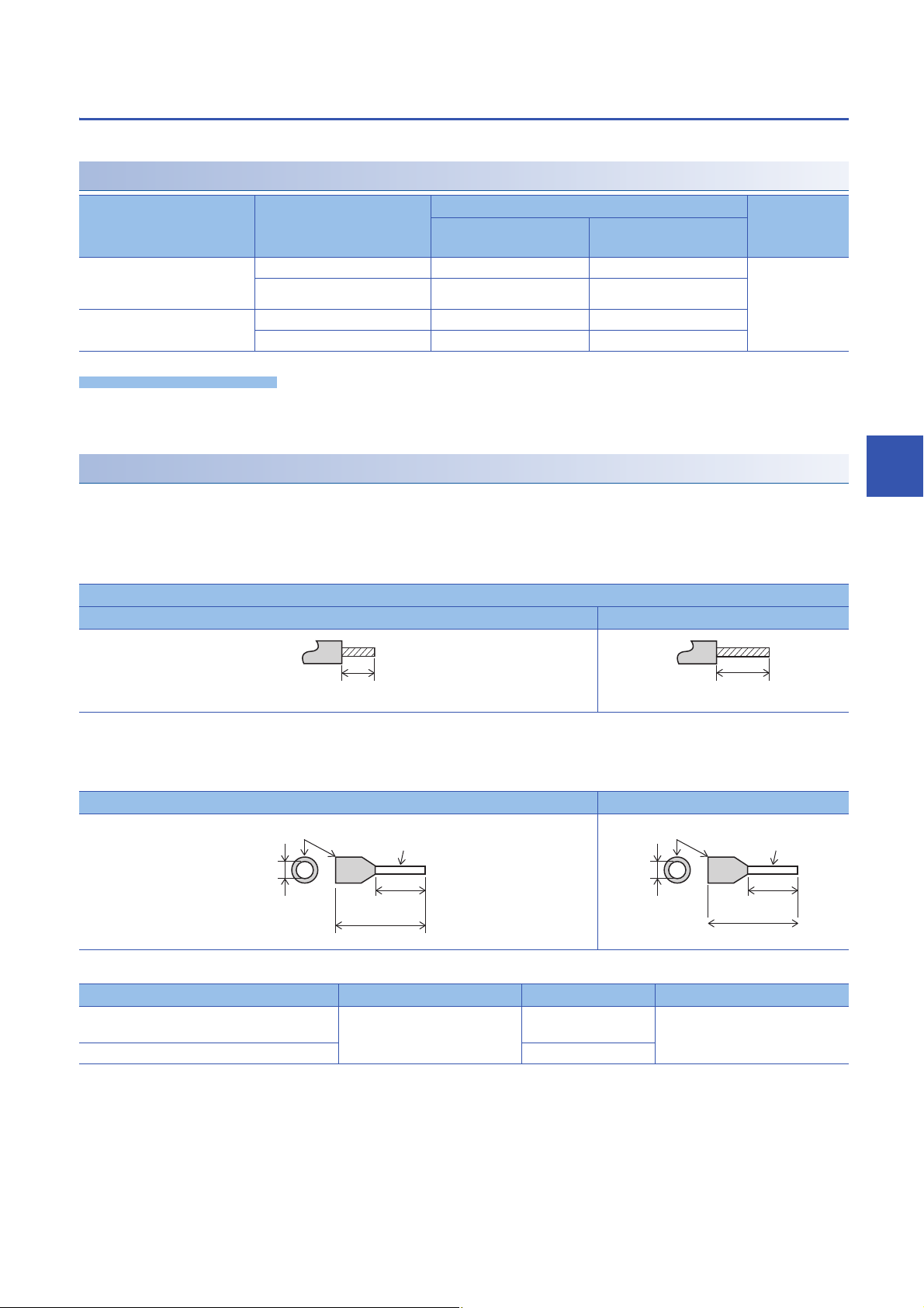
European-type terminal block
Precautions
6 mm
10.5 to 12 mm
2 to 2.5 mm
Insulating sleeve
Contact area
(crimp area)
(0.23")
(0.41" to 0.47")
(0.07" to 0.09")
8 mm
14 mm
2.6 mm
Insulating sleeve
Contact area
(crimp area)
(0.31")
(0.55")
(0.1")
Wire the European-type terminal block in accordance with the following specifications.
Suitable wiring
Built-in analog I/O terminal block
Terminal block for built-in RS-485
communication
Expansion board, expansion
adapter
Number of wires connected
per terminal
One wire 0.2 to 0.5 mm
Two wires 0.2 mm
One wire 0.3 to 0.5 mm
Two wires 0.3 mm
Wire size Tightening
Solid wire, Stranded
wire
2
(AWG24 to 20) 0.2 to 0.5 mm2 (AWG24 to 20) 0.22 to 0.25 Nm
2
(AWG24)
2
(AWG22 to 20) 0.3 to 0.5 mm2 (AWG22 to 20)
2
(AWG22)
Wire ferrule with
insulation sleeve
torque
Do not tighten terminal screws with torque beyond the specified range. Otherwise it may cause equipment failure or
malfunction.
Wire end treatment
Treat stranded and solid wires as they are or use wire ferrules with insulation sleeves for wiring terminals.
■When stranded and solid wires are treated as they are
• Twist the end of stranded wires and make sure that there are no loose wires.
• Do not solder-plate the electric wire ends.
Stripping dimensions of electric wire ends
Built-in analog I/O terminal block, built-in RS-485 communication terminal block Expansion board, expansion adapter
6
5 mm
(0.2")
9 mm
(0.36")
■When wire ferrules with insulation sleeves are used
Depending on the thickness of a wiring sheath used, it may be difficult to insert the sheath into an insulation sleeve. Refer to
the external dimensions as a reference to select wires.
Built-in analog I/O terminal block, built-in RS-485 communication terminal block Expansion board, expansion adapter
<Reference>
Manufacturer Model Crimp tool
Built-in analog I/O terminal block
Terminal block for built-in RS-485 communication
Expansion board, expansion adapter AI 0.5-8 WH
Phoenix Contact GmbH & Co. KG AI 0.5-6 WH CRIMPFOX 6
CRIMPFOX 6T-F
6 WIRING
6.2 Cable Connecting Procedure
77
Page 80

■Tool
For tightening terminals, use a small, commercially-available screwdriver with a straight tip. The recommended
shape is shown in the figure on the right.
■Precautions
When a precision screwdriver with a small grip is used, the specified tightening torque cannot be obtained. Use
the following screwdriver or equivalent product (grip diameter: 25 mm (0.99")) to obtain the tightening torque
specified above.
0.4 mm 2.5 mm
(0.01") (0.09")
<Reference>
Manufacturer Model
Phoenix Contact GmbH & Co. KG SZS 0.42.5
6.3 Grounding
Perform the following.
• Perform class D grounding (Grounding resistance: 100 or less).
• Ground the PLC independently when possible.
• If the PLC cannot be grounded independently, perform the "Common grounding" shown below.
With straight tip
PLC PLC PLC
Independent grounding
(Best condition)
Other
equipment
Shared grounding
(Good condition)
Other
equipment
Other
equipment
Common grounding
(Not allowed)
PLC extension devices (excluding expansion boards and communication adapters)
PLC
Expansion
adapter
Expansion
board
CPU
module
I/O
module
Intelligent
module
Other
equipment
Independent grounding
class D grounding (grounding resistance: 100 or less)
• Use a grounding wire with thickness of AWG 14 (2 mm
2
) or thicker.
• Locate the ground point as close to the PLC as possible to minimize the length of the grounding wire.
78
6 WIRING
6.3 Grounding
Page 81

6.4 Power Supply Wiring
AC power supply (100 to 240 V)
S/S
L
N
0V
Expansion adapter
PL
Power ON
MC
MC
MC MC
24V
CPU module
Input module
S/S
Class D grounding
DC AC
*1
*2
*4
*4
5 V 0 V 24 V
Breaker
24-
24+
*3
FX5
intelligent module
24-
24+
*3
24 V DC
service power
supply output
24 V DC
service power
supply output
FX3
intelligent module
Emergency
stop
Power supply for loads
connected to PLC output
terminals
As for emergency stop
operation, see "DESIGN
PRECAUTIONS" at
"Safety Precautions" field.
DC power
supply
Bus conversion
module
5 V 0 V 24 V
S/S
L
N
0V
24V
Powered
input/output module
*1
5 V 0 V 24 V
5 V 0 V 24 V
5 V 0 V 24 V
5 V 0 V 24 V
5 V 0 V 24 V
Examples of AC power supply wiring
Power supply example for sink input [-common]
6
*1 Connect the AC power supply to the [L] and [N] terminals (common for 100 V AC system and 200 V AC system).
Make sure that the powered input/output module is turned on at the same time as the CPU module or earlier than the CPU module.
*2 Connect the [24V] terminal of the CPU module to the [S/S] terminal of the input module.
*3 Some intelligent function modules may not have power supply terminals.
When using an external power supply, turn on the power supply at the same time as the CPU module or earlier than the CPU module.
When turning off the power, confirm the safety of the system and turn off the power of the PLC (including extension devices) at the same
time.
*4 Do not connect the [24V] terminals (24 V DC service power supply) of the CPU module and the powered input/output module with each
other. Connect the [0V] terminal.
6 WIRING
6.4 Power Supply Wiring
79
Page 82

Power supply example for source input [+common]
AC power supply (100 to 240 V)
S/S
L
N
0V
Expansion adapter
PL
Power ON
MC
MC
MC MC
24V
CPU module
Input module
S/S
Class D grounding
DC AC
*1
*2
*4
*4
Breaker
24-
24+
*3
FX5
intelligent module
24-
24+
*3
24 V DC
service
power supply
output
FX3
intelligent module
Emergency
stop
Power supply for loads
connected to PLC output
terminals
As for emergency stop
operation, see "DESIGN
PRECAUTIONS" at "Safety
Precautions" field.
DC power
supply
Bus conversion
module
5 V 0 V 24 V
5 V 0 V 24 V
S/S
L
N
0V
24V
Powered input/output
module
*1
24 V DC
service
power supply
output
5 V 0 V 24 V
5 V 0 V 24 V
5 V 0 V 24 V
5 V 0 V 24 V
5 V 0 V 24 V
*1 Connect the AC power supply to the [L] and [N] terminals (common for 100 V AC system and 200 V AC system).
Make sure that the powered input/output module is turned on at the same time as the CPU module or earlier than the CPU module.
*2 Connect the [0V] terminal of the CPU module to the [S/S] terminal of the input module.
*3 Some intelligent function modules may not have power supply terminals.
When using an external power supply, turn on the power supply at the same time as the CPU module or earlier than the CPU module.
When turning off the power, confirm the safety of the system and turn off the power of the PLC (including extension devices) at the same
time.
*4 Do not connect the [24V] terminals (24 V DC service power supply) of the CPU module and the powered input/output module with each
other. Connect the [0V] terminal.
80
6 WIRING
6.4 Power Supply Wiring
Page 83

Wiring example for an extension power supply module (sink input [-common])
X
S/S
AC power supply (100 to 240 V)
S/S
L
N
0V
Expansion adapter
PL
Power ON
MC
MC
MC MC
24V
CPU module
Input module
S/S
Class D grounding
DC AC
*1
*2
Breaker
24-
24+
*3
FX5
intelligent module
L
N
*1
*3
Extension power supply module
FX5
intelligent module
Input module
Output module
24-
24+
Wiring precaution:
24 V DC
service power
supply output
Emergency
stop
Power supply for loads connected
to PLC output terminals
As for emergency stop operation,
see "DESIGN PRECAUTIONS" at
"Safety Precautions" field.
Run grounding and power cables from the
top as shown in the following figure.
DC power
supply
Grounding and
power cables
5 V 0 V 24 V
5 V 0 V 24 V
5 V 0 V 24 V
5 V 0 V 24 V
5 V 0 V 24 V
5 V 0 V 24 V
5 V 0 V 24 V
5 V 0 V 24 V
S/S
*2
When external power supply is
supplied to the input circuit
The following example shows wiring for an extension power supply module when sink input [-common] is used.
6
*1 Connect the AC power supply to the [L] and [N] terminals (common for 100 V AC system and 200 V AC system). Make sure that the
power of the extension power supply module is turned on at the same time as the CPU module or earlier than the CPU module.
*2 Connect the [24V] terminal of the CPU module to the [S/S] terminal of the input module.
*3 Some intelligent function modules may not have power supply terminals.
When using an external power supply, turn on the power supply at the same time as the CPU module or earlier than the CPU module.
When turning off the power, confirm the safety of the system and turn off the power of the PLC (including extension devices) at the same
time.
6 WIRING
6.4 Power Supply Wiring
81
Page 84

Wiring example for an extension power supply module (source input [+common])
AC power supply (100 to 240 V)
S/S
L
N
0V
Expansion adapter
PL
Power ON
MC
MC
MC MC
24V
CPU module
Input module
S/S
Class D grounding
DC AC
*1
*2
Breaker
24-
24+
*3
FX5
intelligent module
L
N
S/S
*1
*3
Extension power supply module
FX5
intelligent module
Input module
Output module
24-
24+
Wiring precaution:
24 V DC
service
power supply
output
Emergency
stop
Power supply for loads connected
to PLC output terminals
As for emergency stop operation, see
"DESIGN PRECAUTIONS" at "Safety
Precautions" field.
Run grounding and power cables from the
top as shown in the following figure.
DC power
supply
Grounding and
power cables
5 V 0 V 24 V
5 V 0 V 24 V
5 V 0 V 24 V
5 V 0 V 24 V
5 V 0 V 24 V
5 V 0 V 24 V
5 V 0 V 24 V
5 V 0 V 24 V
*2
When external power supply is
supplied to the input circuit
X
S/S
The following example shows wiring for an extension power supply module when source input [+common] is used.
*1 Connect the AC power supply to the [L] and [N] terminals (common for 100 V AC system and 200 V AC system). Make sure that the
power of the extension power supply module is turned on at the same time as the CPU module or earlier than the CPU module.
*2 Connect the [0V] terminal of the CPU module to the [S/S] terminal of the input module.
*3 Some intelligent function modules may not have power supply terminals.
When using an external power supply, turn on the power supply at the same time as the CPU module or earlier than the CPU module.
When turning off the power, confirm the safety of the system and turn off the power of the PLC (including extension devices) at the same
time.
82
6 WIRING
6.4 Power Supply Wiring
Page 85

6.5 Input Wiring
24V
N
L
X
S/S
0V
The input wiring of the CPU module and I/O modules is explained below.
24 V DC input (Sink and source input type)
For input specifications of the CPU module, refer to Page 19 Input Specifications.
For input specifications of the I/O modules, refer to Page 135 Input specifications.
Sink and source input
■Differences between the sink input circuit and the source input circuit
• Sink input [-common] • Source input [+common]
Sink input means a DC input signal with current-flow from the input
(X) terminal.
When a device such as a transistor output type sensor is
connected, NPN open collector transistor output can be used.
L
N
24V
0 V
S/S
X
Source input means a DC input signal with current-flow into the
input (X) terminal.
When a device such as a transistor output type sensor is
connected, PNP open collector transistor output can be used.
6
■Switching between sink/source inputs
To switch the input type to sink or source input, wire the [S/S] terminal to the [0V] or [24V] terminal.
• Sink input: Connect the [24V] terminal and [S/S] terminal. (Page 87 Sink input [AC power supply type])
• Source input: Connect the [0V] terminal and [S/S] terminal. (Page 88 Source input [AC power supply type])
All inputs (X) of the CPU module can be set to either sink input or source input by selection.
6 WIRING
6.5 Input Wiring
83
Page 86
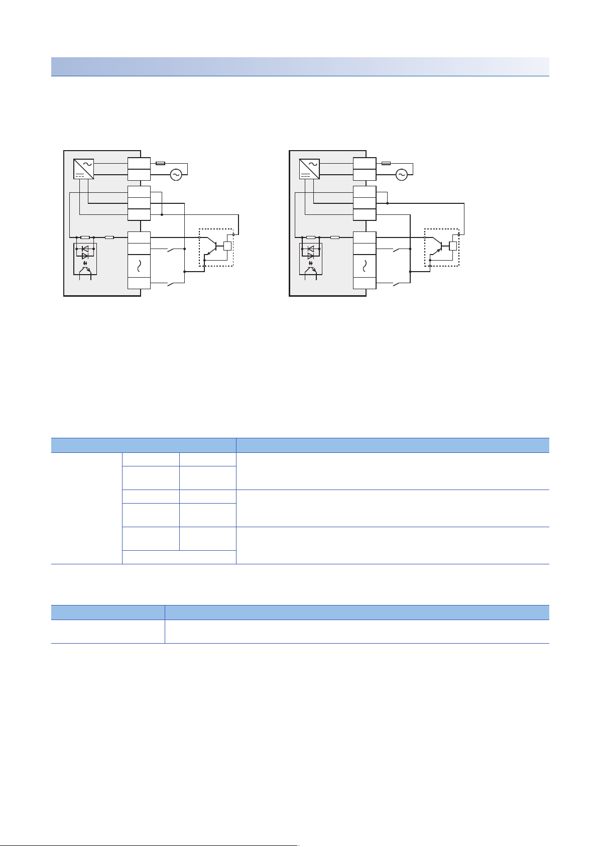
Handling of 24 V DC input
X000
X001
X007
*
*Input impedance
S/S
N
L
100 to 240 V AC
Fuse
24V
0V
■Input terminal
• Sink input • Source input
When a no-voltage contact or NPN open collector transistor output
is connected between an input (X) terminal and the [0V] terminal
and the circuit is closed, the input (X) turns on.
The input display LED turns on.
• RUN terminal setting
X000 to X017 of the CPU module can be used as RUN input terminals
by setting parameters.
MELSEC iQ-F FX5 User's Manual (Application)
When a no-voltage contact or PNP open collector transistor output
is connected between an input (X) terminal and the [24V] terminal
and the circuit is closed, the input (X) turns on.
The input display LED turns on.
Fuse
L
N
100 to 240 V AC
S/S
0V
24V
*
X000
X001
X007
*Input impedance
■Input circuit
• Function of input circuit
The primary and secondary circuits for input are insulated with a photocoupler, and the second circuit is provided with a C-R filter.
The C-R filter is designed to prevent malfunctions caused by chattering of the input contact and noise from the input line.
Input has a response delay switching from ON to OFF and OFF to ON, shown in the following table.
Item Specifications
Input response time
(H/W filter delay)
• Change of filter time
All input circuits have digital filters, and the input response time shown in the following table can be added by setting parameters.
When using this product in an environment with much noise, set the digital filter.
FX5U-32M X000 to X005 ON: 2.5 s or less
FX5U-64M,
FX5U-80M
FX5U-32M X006 to X017 ON: 30 s or less
FX5U-64M,
FX5U-80M
FX5U-64M,
FX5U-80M
I/O module
X000 to X007
X010 to X017
X020 and
subsequent
OFF: 2.5 s or less
OFF: 50 s or less
ON: 50 s or less
OFF: 150 s or less
Item Specifications
Input response time
(Digital filter setting value)
None, 10 s, 50 s, 0.1 ms, 0.2 ms, 0.4 ms, 0.6 ms, 1 ms, 5 ms, 10 ms (initial values), 20 ms, 70 ms
■Input sensitivity
For input signal current and Input sensitivity current of the CPU module, refer to Page 19 Input Specifications.
For input signal current and Input sensitivity current of the I/O modules, refer to Page 135 Input specifications.
84
6 WIRING
6.5 Input Wiring
Page 87
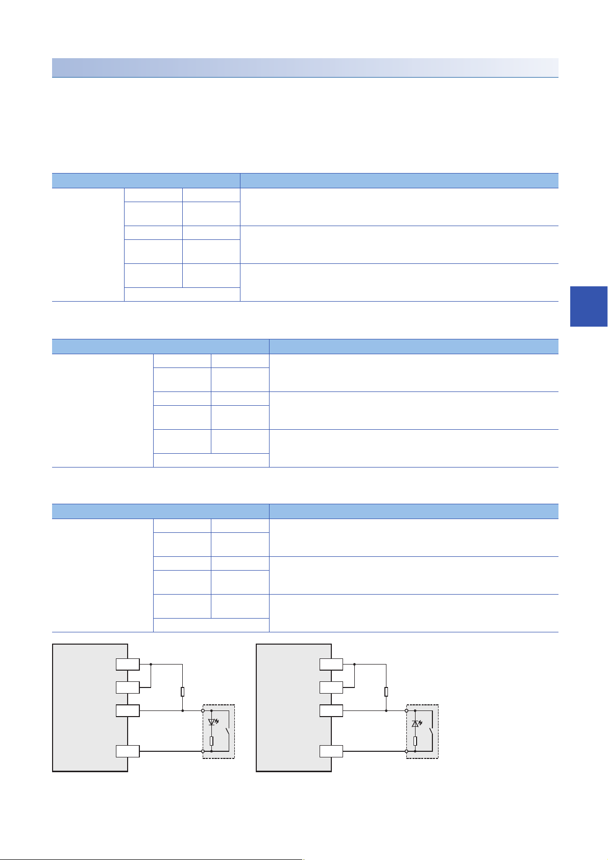
Precautions for connecting input devices
X
24V
Rp
Rb
X
0V
Rp
Rb
24V
S/S S/S
0V
PLC
(sink input)
PLC
(source input)
Bleeder
resistance
Bleeder
resistance
■In the case of no-voltage contact
Use input devices appropriate for low electric current.
If no-voltage contacts for high current (switches) are used, contact failure may occur.
■In the case of input device with built-in series diode
The voltage drop of the series diode should be the following value or less.
Also make sure that the input current is over the input-sensing level while the switches are on.
Item Specifications
Voltage drop FX5U-32M X000 to X005 3.9 V
FX5U-64M,
FX5U-80M
FX5U-32M X006 to X017 4.1 V
FX5U-64M,
FX5U-80M
FX5U-64M,
FX5U-80M
I/O module
■In the case of input device with built-in parallel resistance
Use a device having a parallel resistance Rp (k) of the following value or more.
Item Specifications
Parallel resistance Rp (k) FX5U-32M X000 to X005 14
X000 to X007
X010 to X017
X020 and
subsequent
FX5U-64M,
FX5U-80M
FX5U-32M X006 to X017 15
FX5U-64M,
FX5U-80M
FX5U-64M,
FX5U-80M
I/O module
2.4 V
X000 to X007
X010 to X017
X020 and
subsequent
13
6
If the resistance is less than the above parallel resistance Rp (k), connect a bleeder resistance Rb (k) obtained by the
following formula as shown in the following figure.
Item Specifications
Bleeder resistance Rb (k)FX5U-32M X000 to X005 5 Rp / (14-Rp) or less
FX5U-64M,
FX5U-80M
FX5U-32M X006 to X017 4 Rp / (15-Rp) or less
FX5U-64M,
FX5U-80M
FX5U-64M,
FX5U-80M
I/O module
X000 to X007
X010 to X017
X020 and
subsequent
6 Rp / (13-Rp) or less
6 WIRING
6.5 Input Wiring
85
Page 88

■ In the case of 2-wire proximity switch
X
24V
Rb
I
X
0V
Rb
I
24V
S/S S/S
0V
PLC
(sink input)
PLC
(source input)
Bleeder
resistance
Bleeder
resistance
2-wire
proximity
sensor
2-wire
proximity
sensor
X
S/S
5.6 k
Proximity sensor
PLC
Main circuit
External resistor
(for input current adjustment)
Input current
Adjusted in accordance
with the connected device
Use a two-wire proximity switch whose leakage current, I is 1.5 mA or less when the switch is off.
If the resistance is larger than leakage current, I of 1.5 mA, connect a bleeder resistance Rb (k), obtained by the following
formula as shown in the following figure.
Item Specifications
Bleeder resistance Rb (k)FX5U-32M X000 to X005 7 / (I-1.5) or less
FX5U-64M,
FX5U-80M
FX5U-32M X006 to X017 7 / (I-1.5) or less
FX5U-64M,
FX5U-80M
FX5U-64M,
FX5U-80M
I/O module
X000 to X007
X010 to X017
X020 and
subsequent
9 / (I-1.5) or less
86
■When the input signal cannot be received because the current is insufficient
The current rating for the CPU module in X020 or more and the I/O module is 4 mA.
In some cases, depending on extension devices used, it may not be possible to receive the input signal, due to the insufficient
current. Take the following action in such case.
In the case of capturing high-speed pulses
When capturing pulses of a response frequency of 50 to 200 kHz on using the input X000 to X007 (FX5U-32M is X000 to
X005.), wire the terminals as stated below.
• The wiring length should be 5 m (16'4") or less.
• Use shielded twisted-pair cables for connecting cables. Ground the shield of each shielded cable only on the CPU module
side.
• Connect a 1.5 k (1 W or more) bleeder resistance to the input terminal, so that the sum of the load current of the open
collector transistor output on the mating device and the input current of the CPU module is 20 mA or more.
The above-mentioned restrictions are due to specifications of connecting device (encoder etc.).
Please adjust the cable length and load, for connecting device.
6 WIRING
6.5 Input Wiring
Page 89

Input wiring example
X0
S/S
0V
24V
CPU module
N
L
X1
X0
S/S
X1
Input module
5V0V 24V
Input
terminal
X0
S/S
X1
Input module
5V0V 24V
5V0V 24V
Fuse
24 V DC
Class D grounding
*1
*2
24V
0V
*3
Input
impedance
Input
terminal
Input
terminal
Three-wire
sensor
Three-wire
sensor
Two-wire
proximity
sensor
Sink input [AC power supply type]
6
*1 Handle the power supply circuit properly in accordance with "Power Supply Wiring."
*2 For an input device having a parallel resistance or a two-wire proximity switch, a bleeder resistance may be required.
*3 In the case of sink input wiring, short-circuit the [S/S] and [24V] terminals of the CPU module.
The service power supply or external power supply can be used for all inputs (X) of the CPU module. However
you need to select either one for each CPU module or I/O module. Both power supplies cannot be used
together in the same module.
6 WIRING
6.5 Input Wiring
87
Page 90

Source input [AC power supply type]
X0
S/S
0V
24V
CPU module
N
L
X1
X0
S/S
X1
Input module
5V0V 24V
Input
terminal
X0
S/S
X1
Input module
5V0V 24V
5V0V 24V
Fuse
Class D grounding
*1
*2
Three-wire
sensor
Three-wire
sensor
Two-wire
proximity
sensor
0V
24V
*3
Input
impedance
Input
terminal
Input
terminal
24 V DC
*1 Handle the power supply circuit properly in accordance with "Power Supply Wiring."
*2 For an input device having a parallel resistance or a two-wire proximity switch, a bleeder resistance may be required.
*3 In the case of source input wiring, short-circuit the [S/S] and [0V] terminals of the CPU module.
The service power supply or external power supply can be used for all inputs (X) of the CPU module. However
you need to select either one for each CPU module or I/O module. Both power supplies cannot be used
together in the same module.
88
6 WIRING
6.5 Input Wiring
Page 91

6.6 Output Wiring
The output wiring of the CPU module and I/O modules is explained below.
Relay output
For output specifications of the CPU module, refer to Page 21 Output Specifications.
For output specifications of the I/O modules, refer to Page 136 Output specifications.
Product life of relay output contacts
The product life of relay output contacts varies considerably depending on the load type used.
Note that loads generating reverse electromotive force or rush current may cause poor contact or welding of contacts which
may lead to considerable reduction of the contact product life.
■Inductive load
Inductive loads generate large reverse electromotive force between contacts at shutdown, which may cause arc discharge. At
a fixed current consumption, as the power factor (phase between current and voltage) gets smaller, the arc energy gets larger.
The standard life of contacts used for inductive AC loads, such as general contactors and solenoid valves, is 500,000
operations at 20 VA.
The following table shows the approximate life of a relay based on the results of an operation life test.
• Test condition: 1 sec. ON/1 sec. OFF
Load capacity Contact life
20 VA 0.2 A/100 V AC 3,000,000 times
0.1 A/200 V AC
35 VA 0.35 A/100 V AC 1,000,000 times
0.17 A/200 V AC
80 VA 0.8 A/100 V AC 200,000 times
0.4 A/200 V AC
6
The product life of relay contacts becomes considerably shorter than the above conditions when the rush overcurrent is shut
down.
Please refer to the following measures regarding the inductive load.
Page 91 Contact protection circuit for inductive loads
Some types of inductive loads generate rush current 5 to 15 times the stationary current at activation. Make sure that the rush
current does not exceed the current corresponding to the maximum specified resistance load.
■Lamp load
Lamp loads generally generate rush current 10 to 15 times the stationary current. Make sure that the rush current does not
exceed the current corresponding to the maximum specified resistance load.
■Capacitive load
Capacitive loads can generate rush current 20 to 40 times the stationary current. Make sure that the rush current does not
exceed the current corresponding to the maximum specified resistance load.
Capacitive loads such as capacitors may be present in electronic circuit loads including inverters.
■Resistance load
For maximum load specifications of resistance load, refer to the following.
For output specifications of the CPU module, refer to Page 21 Output Specifications.
For output specifications of the I/O modules, refer to Page 136 Output specifications.
6 WIRING
6.6 Output Wiring
89
Page 92

Handling of relay output
PLCs
Load
24 V DC
Fuse
Y0
Y1
COM0
Load
100 V AC
Fuse
Y4
Y5
COM1
■Output terminal
One common terminal is used for 4 or 8 relay output points.
The common terminal blocks can drive loads of different circuit voltage systems (for example,100 V AC and 24 V DC).
■External power supply
Use an external power supply of 30 V DC or less or 240 V AC or less (250 V AC or less when the module does not comply
with CE, UL, cUL standards) for loads.
■Insulation of circuit
The PLC internal circuit and external load circuits are electrically insulated between the output relay coil and contact.
The common terminal blocks are separated from one another.
■Display of operation
When power is applied to the output relay coil, the LED is lit, and the output contact is turned on.
■Response time
The response time of the output relay from when the power is applied to the coil until the output contact is turned on and from
when the coil is shut off until the output contact is turned off is approx. 10 ms.
■Output current
At a circuit voltage of 240 V AC or less (250 V AC or less when the module does not comply with CE, UL, cUL standards), a
resistance load of 2 A per point or an inductive load of 80 VA or less (100 V AC or 200 V AC) can be driven.
For the life of the contact for switching an inductive load, refer to Page 89 Inductive load.
When an inductive load is switched, connect a diode (for commutation) or a surge absorber in parallel with this load.
DC circuit AC circuit
Diode (for commutation) Surge absorber
■Open circuit leakage current
There is no leakage current when the outputs are OFF.
90
6 WIRING
6.6 Output Wiring
Page 93

Wiring precautions
+
-
Inductive load
Diode (for commutation)
PLC output contact
Inductive load
PLC output contact
Surge
absorber
Interlock
PLC output
contact
PLC output
contact
Limit of forward
rotation
Limit of reverse
rotation
Forward
rotation
Reverse
rotation
■Protection circuit for load short-circuiting
A short-circuit at a load connected to an output terminal could cause
burnout at the output element or the PCB. To prevent this, a protection
fuse should be inserted at the output.
Fuse
■Contact protection circuit for inductive loads
An internal protection circuit for the relays is not provided for the relay output circuit in this product. It is recommended to
use inductive loads with built-in protection circuits.
When using loads without built-in protection circuits, insert an external contact protection circuit, etc. to reduce noise and
extend product life.
•
DC circuit
Connect a diode in parallel with the load.
The diode (for commutation) must comply with the following
specifications.
Reverse voltage: 5 to 10 times the load voltage
Forward current: Load current or more
•
AC circuit
Connect a surge absorber (CR composite parts like surge killer,
spark killer, etc.) parallel to the load. Select a surge absorber with
voltage rating that is suitable for the output used.
Electrostatic capacity: Approx. 0.1 F
Resistance: Approx. 100 to 200
Load
Y0
COM0
PLCs
6
■Interlock
For loads such as forward/reverse contactors, etc., where a
hazardous condition could result if switched ON simultaneously, an
external interlock should be provided for interlocking along with an
interlock in the PLC program, as shown to the right.
■In-phase
PLC output contacts (*) should be used in an "in-phase" manner.
*
*
*
*
6 WIRING
6.6 Output Wiring
91
Page 94

Transistor output
Load
Y
Fuse
DC power supply
A number is entered in the of [COM].
COM
Load
Y
Fuse
DC power supply
A number is entered in the of [+V].
+V
PLCs
Load
Fuse
Y0
COM0
Load
Fuse
COM1
Sink output type
Y1
Y4
Y5
DC power
supply
DC power
supply
For output specifications of the CPU module, refer to Page 21 Output Specifications.
For output specifications of the I/O modules, refer to Page 136 Output specifications.
Sink and source output
Sink output and source output products are available for transistor outputs of the CPU module and I/O modules.
■Differences in circuit
• Sink output [-common] • Source output [+common]
Output to make load current flow into the output (Y) terminal is
called sink output.
Handling of transistor output
■Output terminal
4 or 8 transistor output points are covered by one common terminal.
• Sink output • Source output
Connect each COM (number) terminal to the minus side of
the load power supply.
The COM terminals are not connected internally.
Output to make load current flow out of the output (Y) terminal
is called source output.
Connect +V (number) terminal to the plus side of the load
power supply.
The +V terminals are not connected internally.
Source output type
Fuse
Fuse
Load
DC power
supply
Load
DC power
supply
Y0
Y1
+V0
Y4
Y5
+V1
PLCs
■External power supply
For driving the load, use a smoothing power supply of 5 to 30 V DC that can output current two or more times the current
rating of the fuse connected to the load circuit.
■Insulation of circuit
The internal circuit of the PLC and the output transistor are insulated with a photocoupler.
The common blocks are separated from one another.
■Display of operation
Operation indicator LEDs are built into the CPU module and output modules, and turn ON when photocouplers are activated,
and the transistors are switched on.
92
6 WIRING
6.6 Output Wiring
Page 95

■Response time
PLCs
Y
COM0
Load
Fuse
Sink output type
Y
+V0
PLCs
Load
Fuse
Source output type
Time taken from when the photocoupler of the module is driven (or shut off) to when the transistor is turned on (or off) differs
depending on the output terminal used. For specifications of each module, refer to the following.
For output specifications of the CPU module, refer to Page 21 Output Specifications.
For output specifications of the I/O modules, refer to Page 136 Output specifications.
The transistor OFF time is longer under lighter loads. For example, under a load of 24 V DC 40 mA, the
response time is approx. 0.3 ms.
When response performance is required under light loads, provide a dummy resistor as shown below to
increase the load current.
• Sink output type • Source output type
LoadFuse
Dummy
resistor
Y
COM0
PLCs
LoadFuse
Dummy
resistor
Y
+V0
PLCs
■Output current
Maximum load differs for each module. For specifications of each module, refer to the following.
For output specifications of the CPU module, refer to Page 21 Output Specifications.
For output specifications of the I/O modules, refer to Page 136 Output specifications.
When driving a semiconductor device, carefully check the input voltage characteristics of the device.
■Open circuit leakage current
0.1 mA or less
Wiring precautions
■Protection circuit for load short-circuiting
A short-circuit at a load connected to an output terminal could cause burnout at the output device or the PCB.
To prevent this, a protection fuse should be inserted at the output. Use a load power supply capacity that is at least 2
times larger than the load current.
6
6 WIRING
6.6 Output Wiring
93
Page 96

■Contact protection circuit for inductive loads
PLCs
Inductive load
Fuse
Source output type
Y
+V0
+-
Forward rotation
Reverse rotation
Sink output type
Interlock
PLC output
element
Limit of forward
rotation
Limit of reverse
rotation
When an inductive load is connected, connect a diode (for commutation) in parallel with the load as necessary.
The diode (for commutation) must comply with the following specifications.
Standard
Reverse voltage 5 to 10 times as high as the load voltage
Forward current Load current or larger
Sink output type
Inductive load
Fuse
Y
COM0
PLCs
■Interlock
For loads such as forward/reverse contactors, etc., where a hazardous condition could result if switched ON simultaneously,
an external interlock should be provided for interlocking along with an interlock in the PLC program, as shown below.
Source output type
Limit of forward
rotation
Limit of reverse
rotation
Interlock
PLC output
element
+
Forward rotation
Reverse rotation
94
6 WIRING
6.6 Output Wiring
Page 97

Output wiring example
Y0
COM0
Y7
Y0
COM1
Y7
AC power supply (100 to 240 V)
PL
Power ON
MC
MC
MC MC
Load
Load
Fuse
*1
Fuse
*1
Fuse
*1
Fuse
*1
Fuse
*1
Breaker
Y0
COM0
Y14
COM3
Y4
COM1
*2
Emergency
stop
Power supply for loads connected to
PLC output terminals
As for emergency stop operation, see "DESIGN
PRECAUTIONS" at "Safety Precautions" field.
DC power
supply
CPU module
relay output
Output module
relay output
Relay output
6
*1 The output circuit of the PLC does not have a built-in fuse.
Provide a fuse suitable for each load to prevent melting of the wires on the circuit board caused by output device breakdown due to load
short-circuiting.
*2 "" represents vacant terminals.
6 WIRING
6.6 Output Wiring
95
Page 98

Transistor output
Y0
COM0
Y7
Y0
COM1
Y7
Load
PL
Power ON
MC
MC
MC MC
DC power supply
Load
Fuse
*1
Fuse
*1
Load
Load
Fuse
*1
Fuse
*1
AC power supply (100 to 240 V)
Breaker
Y0
COM0
Y14
COM3
Y4
COM1
*2
Emergency
stop
Power supply for loads connected to
PLC output terminals
As for emergency stop operation, see "DESIGN
PRECAUTIONS" at "Safety Precautions" field.
CPU module transistor
output (sink)
Output module
transistor output (sink)
■Sink output type
*1 The output circuit of the PLC does not have a built-in fuse.
Provide a fuse suitable for each load to prevent melting of the wires on the circuit board caused by output device breakdown due to load
short-circuiting.
*2 "" represents vacant terminals.
96
6 WIRING
6.6 Output Wiring
Page 99

■Source output type
Y0
+V0
Y7
Y0
+V1
Y7
PL
Power ON
Emergency
stop
MC
MC
MC MC
DC power supply
Load
Load
Fuse
Fuse
AC power supply (100 to 240 V)
Breaker
Load
Load
Fuse
*1
Fuse
*1
Y0
+V0
Y14
+V3
Y4
+V1
*2
Power supply for loads connected to
PLC output terminals
As for emergency stop operation, see "DESIGN
PRECAUTIONS" at "Safety Precautions" field.
CPU module transistor
output (source)
Output module transistor
output (source)
6
*1 The output circuit of the PLC does not have a built-in fuse.
Provide a fuse suitable for each load to prevent melting of the wires on the circuit board caused by output device breakdown due to load
short-circuiting.
*2 "" represents vacant terminals.
6 WIRING
6.6 Output Wiring
97
Page 100

6.7 Analog Wiring
CH No. goes in of V+, CH.
CH
33 k
82.7 k
V-
V+
Shield *1
*2
Class D
grounding
V-
V+
Class D grounding*2
Shield*1
Wiring to the built-in analog I/O terminals of the CPU module is explained below.
For specifications of the built-in analog I/O terminals of the CPU module, refer to Page 25 Built-in Analog Specifications.
Analog input wiring
*1 For analog input wiring, use shielded twisted-pair cables (double-core type). Separate them from other power lines or lines which can be
induced by others.
*2 For unused channels, short-circuit the "V+" and "V-" terminals.
Analog output wiring
*1 For analog output wiring, use shielded twisted-pair cables (double-core type). Separate them from other power lines or lines which can
be induced by others.
*2 Ground a shielded cable at one point on the signal receiving side.
98
6 WIRING
6.7 Analog Wiring
 Loading...