

Mitsubishi FR-BU2-1.5K, FR-BU2-3.7K, FR-BU2-30K, FR-BU2-55K, FR-BU2-H7.5K Instruction Manual
...
INVERTER
INSTRUCTION MANUAL
Brake Unit
FR-BU2-1.5K to 55K
FR-BU2-H7.5K to H75K
Thank you for choosing this Mitsubishi Inverter option unit.
This instruction manual gives handling information and precautions for use of this equipment.
Incorrect handling might cause an unexpected fault. Before using the equipment, please read
this manual carefully to use the equipment to its optimum performance.
Please forward this manual to the end user.
This section is specifically about safety matters
Do not attempt to install, operate, maintain or inspect this product until you have read through
this instruction manual and appended documents carefully and can use the equipment
correctly. Do not use this product until you have a full knowledge of the equipment, safety
information and instructions.
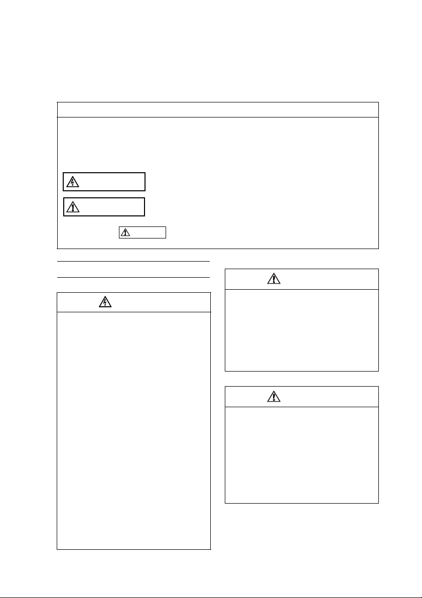
In this instruction manual, the safety instruction levels are classified into "WARNING" and
"CAUTION".
Assumes that incorrect handling may cause hazardous conditions,
WARNING
CAUTION
resulting in death or severe injury.
Assumes that incorrect handling may cause hazardous conditions,
resulting in medium or slight injury, or may cause physical damage
only.
Note that even the level may lead to a serious consequence according to conditions.
Please follow the instructions of both levels because they are important to personnel safety.
SAFETY INSTRUCTIONS
1. Electric Shock Prevention
•
While power is on or when the brake unit is
running, do not open the front cover. You
may get an electric shock.
•
Do not run the brake unit with the front
cover removed. Otherwise, you may access
the exposed high-voltage terminals and
charging part and get an electric shock.
•
Even if power is off, do not remove the front
cover except for wiring or periodic
inspection. You may access the charged
inverter connected to the brake unit and get
an electric shock.
•
Before starting wiring or inspection, check
to make sure that the 3-digit LED brake unit
monitor is off, wait for at least 10 minutes
after the power supply has been switched
off, and check to make sure that there are
no residual voltage using a tester or the
like. The brake unit connected to the brake
unit is charged with high voltage for some
time after power off and it is dangerous.
•
Must be earthed (grounded).
•
Any person who is involved in the wiring or
inspection of this equipment should be fully
competent to do the work.
•
Always install the brake unit before wiring.
Otherwise, you may get an electric shock or
be injured.
•
Do not operate a switch with wet hands.
You may get an electric shock.
•
Do not subject the cables to scratches,
excessive stress, heavy loads or pinching.
Otherwise you may get an electric shock.
CAUTION
WARNING
2. Fire Prevention
CAUTION
• Mount the brake unit and resistor unit to
incombustible material. Installing it to
combustible materials directly or near
combustible materials can cause a fire.
• Turn off power when an alarm signal is
output. Otherwise, the brake resistor may
excessively overheat due to damage of the
brake transistor and such, causing a fire.
• Do not connect the resistor unit directly to
the DC terminals P/+ and N/-. This could
cause a fire.
3. Injury Prevention
CAUTION
• Apply only the voltage specified in the
instruction manual to each terminal.
Otherwise, burst, damage, etc. may occur.
• Ensure that the cables are connected to
the correct terminals. Otherwise, burst,
damage, etc. may occur.
• Always make sure that polarity is correct
to prevent damage, etc. Otherwise, burst,
damage may occur.
• While power is on or for some time after
power-off, do not touch the brake resistor as
it will be extremely hot. Doing so can cause
burns.
A-1
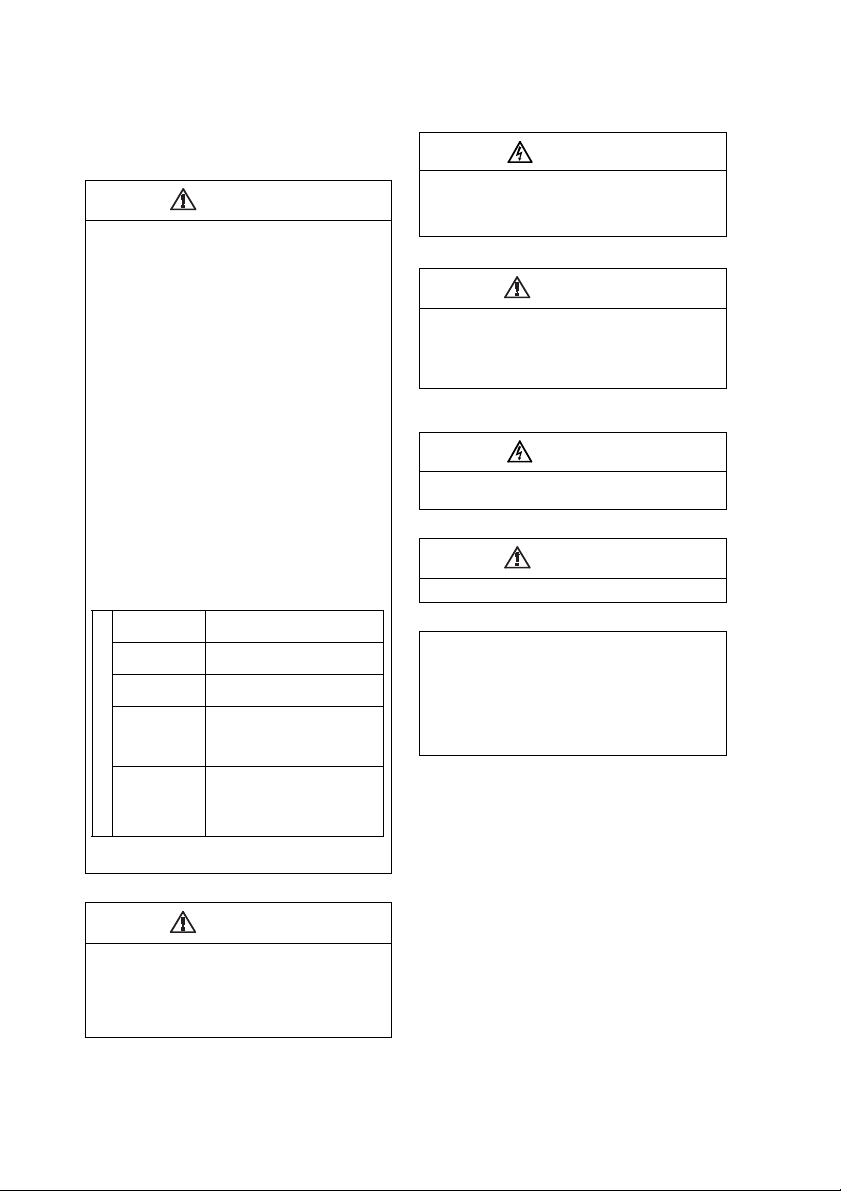
4. Additional Instructions
Also note the following points to prevent an
accidental failure, injury, electric shock, etc.
1) Transportation and mounting
CAUTION
• Transport the product using the correct
method that corresponds to the weight.
Failure to observe this could lead to
injuries.
• Do not stack the brake unit boxes higher
than the number recommended.
• Install the product in a place which can
withstand its weight according to the
information in the instruction manual.
• Do not install or operate the option unit if it
is damaged or has parts missing.
• When carrying the brake unit, do not hold
it by the front cover. It may fall off or fail.
• Do not stand or rest heavy objects on the
product.
• Check that the mounting orientation is
correct.
• Prevent screws, metal fragments or other
conductive bodies or oil or other
flammable substance from entering the
brake unit.
• As this brake unit is a precision
instrument, do not drop or subject it to
impact.
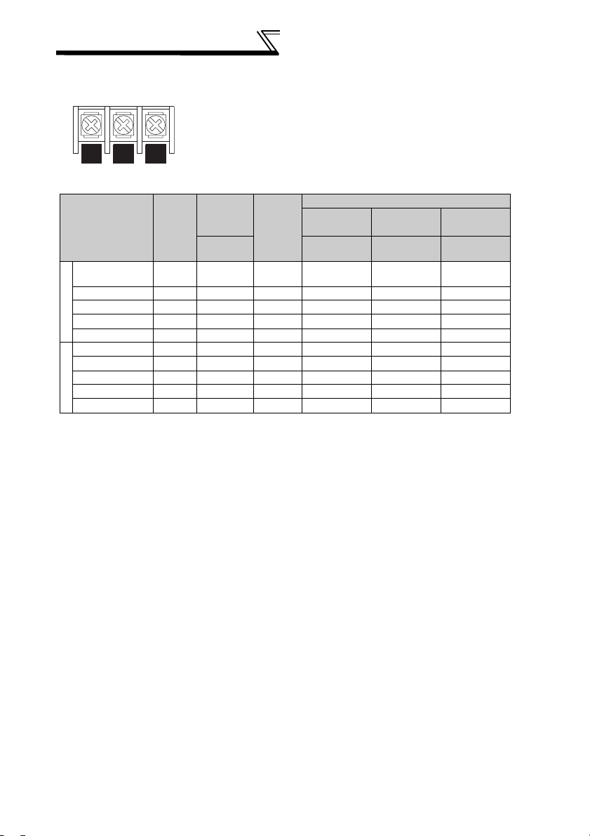
• Use the brake unit under the following
environmental conditions: Failure to fallow
may damage the product.
Ambient
temperature
Ambient
humidity
Storage
temperature
Atmosphere
Environment
Altitude/
vibration
*1Temperature applicable for a short time,
e.g. in transit.
(2) Trial run
-10°C to 50°C
(non-freezing)
90% RH or less
(non-condensing)
-20°C to 65°C *1
Indoors (free from
corrosive gas, flammable
gas, oil mist, dust and
dirt)
Maximum 1000m above
sea level, 5.9m/s
(conforms to JIS C
60068-2-6)
2
or less
3) Usage
WARNING
• Do not modify the equipment.
• Do not perform parts removal which is not
instructed in this manual. Doing so may
lead to fault or damage of the product.
(4) Emergency stop
CAUTION
• Provide a safety backup such as an
emergency brake which will prevent the
machine and equipment from hazardous
conditions if the inverter and brake unit
fail.
(5) Maintenance, inspection and parts
replacement
WARNING
• Do not test the brake unit with a megger
(measure insulation resistance).
(6) Disposal
CAUTION
• Treat as industrial waste.
(7) General instruction
Many of the diagrams and drawings in this
Instruction Manual show the products
without a cover, or partially open. Never
operate the products in this manner.
Always replace the cover and follow this
Instruction Manual when operating the
products.
CAUTION
• Before starting operation, confirm and
adjust the parameters. Setting parameter
different from the one set in the resistor
connected may not exhibit the best
performance or may cause resistor
overheat or alarm.
A-2
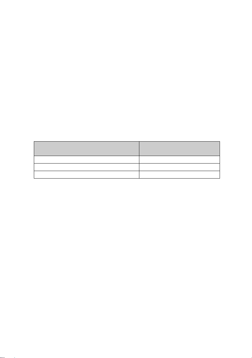
Brake unit (FR-BU2 type)
When running the motor with the FR series inverter, use this option unit
when a large brake torque is necessary such as when the motor is made to
run by the load, quick decerelation is required, etc.
Following three types of brake resistor as in the table below can be
connected to this option unit. FR-BU2 type break unit can be used as
substitute of the existing brake units (BU type, FR-BU-(H) type, MT-BU5
type).
Do not operate the conventional brake unit and FR-BU2 in parallel. Doing so
could cause an alarm or failure. Change all units to the FR-BU2 to operate in
parallel and connect the master/slave signal.
Compatible Brake Resistor and
Resistor Unit
GRZG type brake resistor BU type
FR-BR-(H) type resistor unit FR-BU-(H)
MT-BR5 type resistor unit MT-BU5 type
Perform wiring and parameter setting referring to page 15
Conventional Brake Unit
as the wiring
method and parameter setting method differ according to the brake resistor
combined.

CONTENTS
1 PRODUCT CHECKING AND PARTS IDENTIFICATION.................. 1
2 INSTALLATION ................................................................................. 2
3 WIRING ............................................................................................. 4
3.1 Terminals............................................................................................ 4
3.1.1 Brake unit...............................................................................................4
3.1.2 Resistor unit.........................................................................................11
3.2 Combinations of Brake Resistors for Brake
Unit and Used Wires......................................................................... 13
3.3 External Connection Diagram........................................................... 14
3.3.1 Connection with the inverter ................................................................14
3.4 Connection Example with the GRZG Type Brake Resitor ............... 16
3.4.1 When connecting one inverter and one brake unit .............................16
3.4.2 When connecting several brake units to one inverter.......................... 18
3.4.3 Master/slave operation when connecting several brake units ............. 19
3.5 FR-BR-(H) Connection Example with Resistor Unit ........................21
3.5.1 When connecting one inverter and one brake unit ..............................21
3.5.2 When connecting several brake units to one inverter.......................... 22
3.5.3 Master/slave operation when connecting several brake units ............. 23
3.6 Connection Example with MT-BR5 Type Resistor Unit ...................24
3.6.1 When connecting one inverter and one brake unit ..............................24
3.6.2 When connecting several brake units to one inverter.......................... 25
3.6.3 Master/slave operation when connecting several brake units ............. 26
3.7 Wiring Instructions ............................................................................28
4 OPERATION ................................................................................... 30
4.1 Control Panel.................................................................................... 30
4.2 Basic Operation ................................................................................31
4.3 Parameter List .................................................................................. 32
4.3.1 Mode switchover (Pr.0)........................................................................ 33
4.3.2 Multi-function monitor display (Pr.1, Pr.78).......................................... 34
4.3.3 Input terminal function selecttion (Pr.2, Pr.3).......................................36
4.3.4 Parameter write disable selection (Pr. 77)........................................... 37
4.3.5 Parameter clear ...................................................................................38
4.3.6 Alarm history clear ...............................................................................39
5 PROTECTIVE FUNCTIONS ........................................................... 40
5.1 Causes and Corrective Actions ........................................................ 40
I

5.2 Correspondence Between Digital and Actual Characters ................ 42
6 SPECIFICATIONS .......................................................................... 43
6.1 Brake Unit ........................................................................................ 43
6.2 Brake Resistor/Resistor Unit ............................................................ 43
7 PRECAUTIONS FOR MAINTENANCE AND INSPECTION ........... 44
7.1 Precautions for Maintenance and Inspection ................................... 44
7.2 Inspection Item................................................................................. 44
7.3 Periodic Inspection........................................................................... 45
7.4 Daily and Periodic Inspection........................................................... 46
7.5 Replacement of Parts....................................................................... 47
8 SELECTION .................................................................................... 48
9 OUTLINE DIMENSION DRAWINGS............................................... 51
10INSTRUCTIONS FOR UL, CSA STANDARD COMPLIANCE........ 56
II

MEMO
PRODUCT CHECKING AND
PARTS IDENTIFICATION
1 PRODUCT CHECKING AND PARTS
IDENTIFICATION
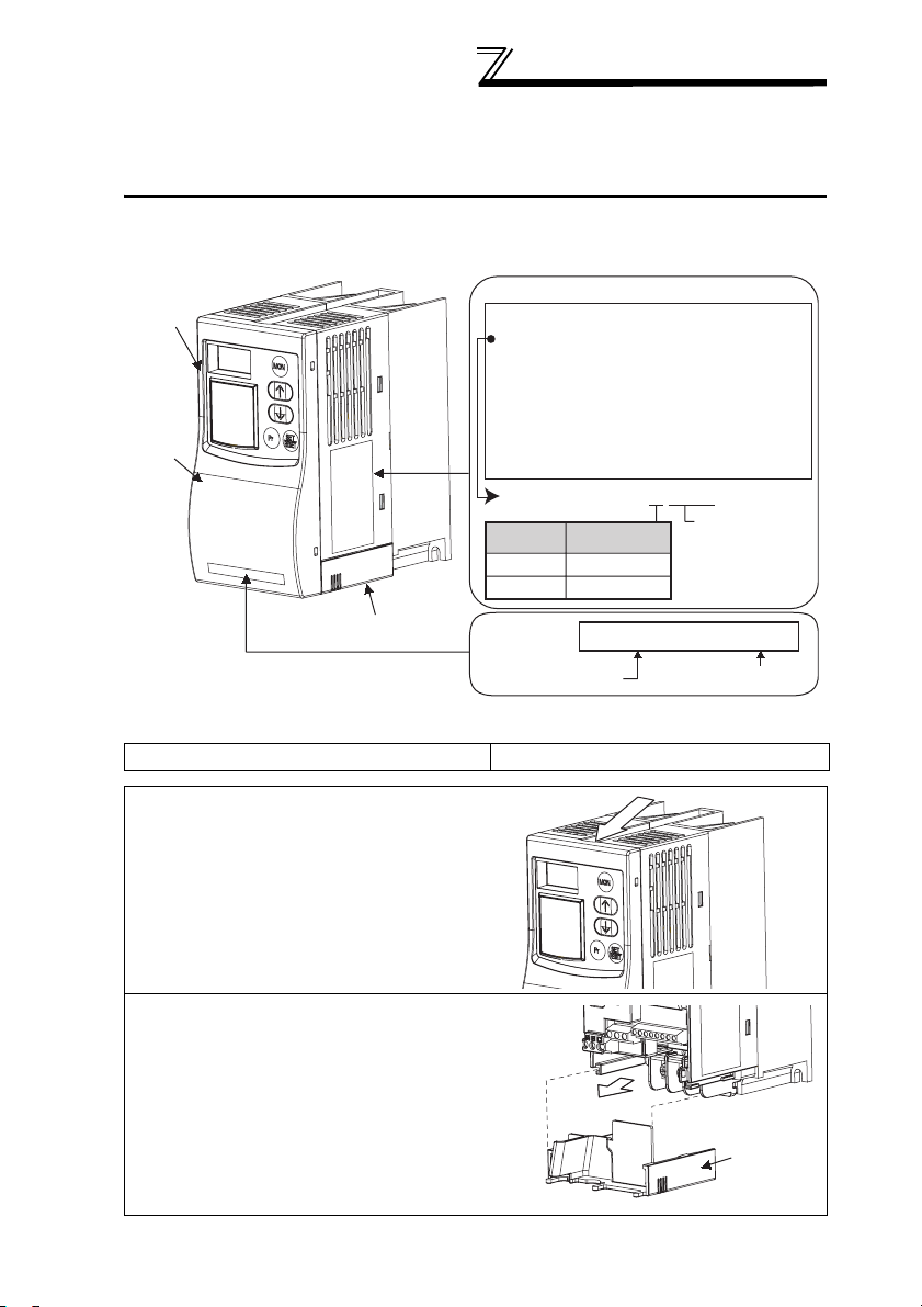
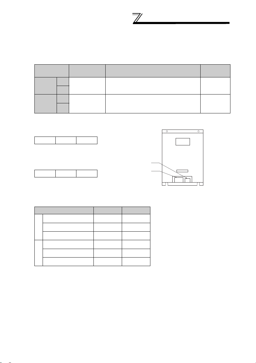
(1) Unpack the option unit and confirm that the product is as you ordered
and intact.
Operation
panel
Rating plate
MITSUBISHI BRAKE UNIT
MODEL FR-BU2-15K
for 200V class INVERTER
Front
cover
Wiring cover
SERIAL : XXXX
MITSUBISHI ELECTRIC CORPORATION
MADE IN JAPAN
MODEL FR-BU2- H □□K
Applied power
No.
supply voltage
H
plate
200V class
400V class
Not used
Capacity
Brake unit type
FR-BU2-15K XXXXXX
Applied motor
capacity (kW)
SERIAL number
(2) Make sure that the package includes all accessories.
Brake unit (FR-BU2).........................1 Instruction manual ........................... 1
• Removal and reinstallation of the
front cover
Remove the front cover by pulling it
toward you in the direction of arrow.
To reinstall, match the cover to the
brake unit front and install it straight.
• Removal and reinstallation of the
wiring cover
The cover can be removed easily by
pulling it toward you.
To reinstall, fit the cover to the brake
Wiring cover
unit along the guides.
1
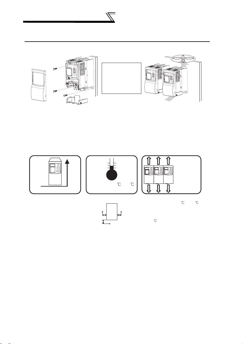
INSTALLATION
2 INSTALLATION
Enclosure surface mounting
Encasing multiple brake units
Remove the
front cover and
wiring cover to
fix the brake unit
to the surface.
When encasing multiple
brake units, install them
Leave enough clearances as
a cooling measure.
•Install the brake unit under the following conditions.
Vertical mounting
Vertical
Ambient temperature
and humidity
Temperature: -10 to 50
Humidity: 90%RH maximum
Brake unit
Measurement
position
5cm
Measurement
position
5cm5cm
in parallel as a cooling
measure.
* Permissible ambient
between brake units should be
Clearances
10cm or more
Brake units
can be closely
attached when
mounting in
lateral direction.*
10cm or more
temperature is -10 to 40
when mounting brake units
closely-attached. When
ambient temperature exceeds
40 , clearances
1cm or more.
2
INSTALLATION
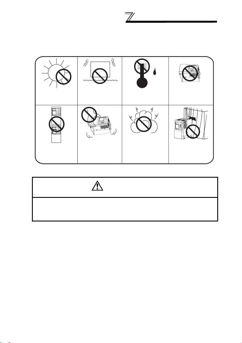
• The brake unit consists of precision mechanical and electronic parts. Never
install or handle it in any of the following conditions as doing so could cause
an operation fault or failure.
Horizontal
placement
Mounting to
combustible
material
Direct sunlight
Vertical mounting
(when mounting
inside an enclosure)
Vibration
2
(5.9m/s
or more)
Transportation by
holding the front
cover
High temperature,
high humidity
Oil mist,
flammable gas,
corrosive gas,
fluff, dust, etc.
CAUTION
Mount the brake unit and resistor unit to incombustible material.
Installing it to combustible materials directly or near combustible
materials can cause a fire.
3
WIRING
3 WIRING
3.1 Terminals
3.1.1 Brake unit
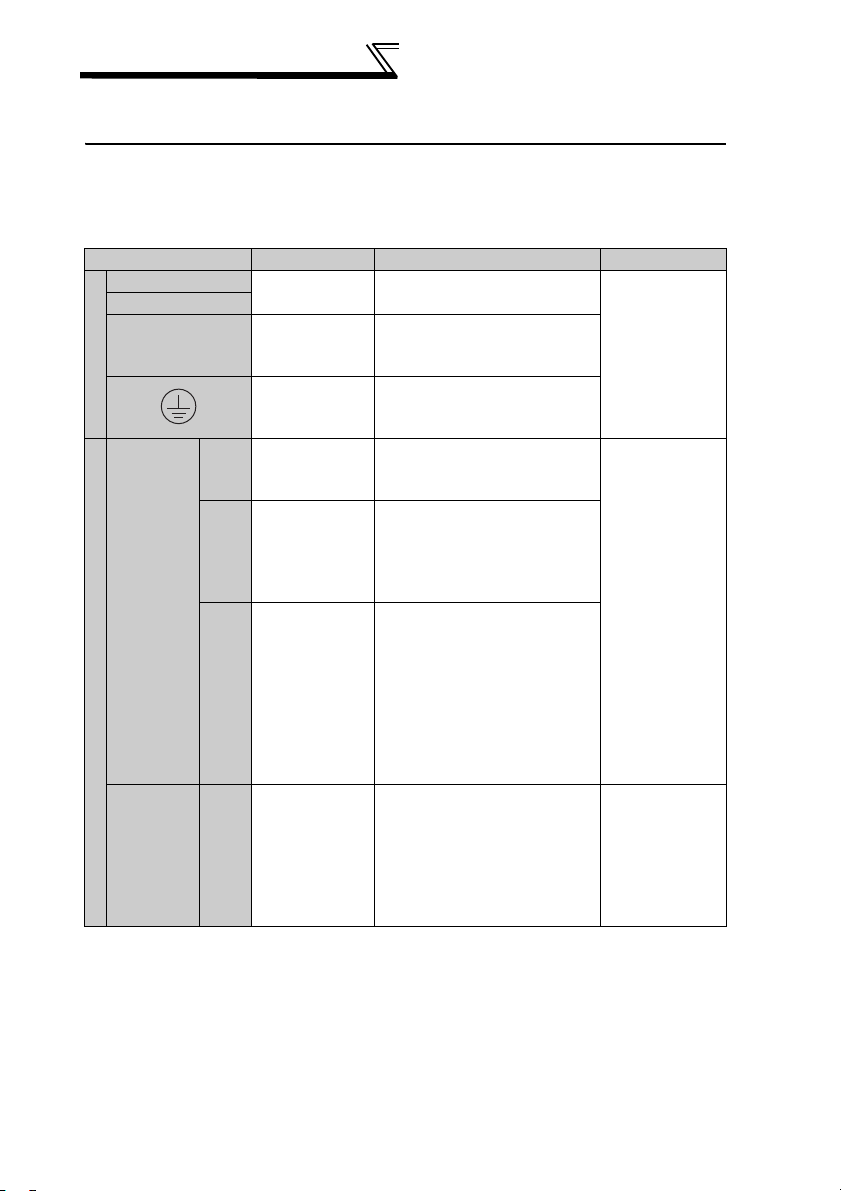
Terminal Symbol Terminal Name Description Rating
P/+
N/-
PR*1
Main circuit
Contact
input
Control circuit
Master/
slave
signal
*1 Only a brake resistor should be connected to terminal PR. Doing so may damage the
brake unit.
*2 BUE-SD is connected with a jumper in the initial status. Remove a jumper when
using this signal. (When terminals are open, brake unit is not operated.)
*3 Do not connect terminals SD, PC and MSG each other or to the ground. Doing so
may damage the brake unit.
For sink logic (initial status), terminal SD acts as the common terminal of contact
input. For source logic (initial status), terminal PC acts as the common terminal of
contact input.
Brake unit input
terminal
Resistor
connection
terminal
Earth (Ground)
Brake operation
BUE
permission
signal
RES Reset input
Contact input
SD
*3
common
Brake
MSG
transistor
*3
driving signal
Connect to the inverter
terminal P and N.
Connect the brake resistor.
For earthing (grounding) the
brake unit. Must be earthed
(grounded).
Controls the brake operation.
Turning on the signal enables
brake operation.
Used to reset alarm output
provided when protective
circuit is activated. Turn on the
RES signal for more than 0.1s,
then turn it off.
Common terminal of the
control input
Brake transister driving signal
common
(for master/slave operation,
when connecting several brake
units to one inverter in parallel,
connect this signal to terminals
of other brake units.)
Brake transistor driving signal
terminal
(For master/slave operation,
when connecting several brake
units to on inverter in parallel,
connect this signal to terminals
of other brake units.)
*2
---
Voltage at
opening :
21 to 27VDC
Controls by open
collector output
or no voltage
contact signal.
---
4
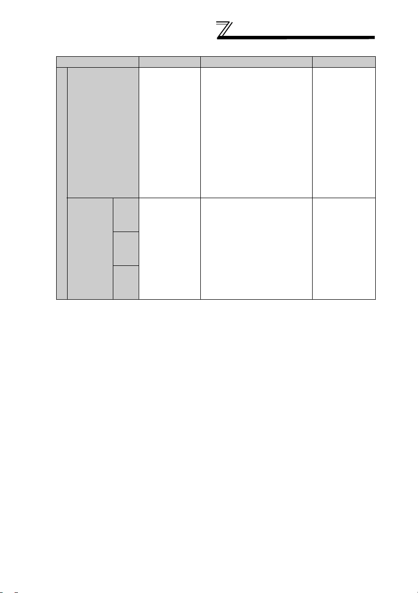
Terminal Symbol Terminal Name Description Rating
When connecting the transistor
output (open collector output),
such as a programmable
External
transistor
PC *3
Control circuit
Relay
output
*3 Do not connect terminals SD, PC and MSG each other or to the ground.
Doing so may damage the brake unit.
For sink logic (initial status), terminal SD acts as the common terminal of contact
input. For source logic (initial status), terminal PC acts as the common terminal of
contact input.
common,
Contact input
common
(source)
A
Relay output 1
B
(Alarm output)
C
controller (PLC), connect the
positive external power supply
for transistor output to this
terminal to prevent a
malfunction caused by
undesirable currents.
When source logic has been
selected, this terminal serves
as a contact input common
terminal.
1 changeover contact output
indicates that the brake unit
protective function has
activated.
• Normal
Across B-C: Continuity
Across A-C: Discontinuity
• Alarm
Across B-C: Disontinuity
Across A-C: Continuity
230VAC 0.3A
30VDC 0.3A
WIRING
---
5
WIRING
• Terminal arrangement of the main circuit terminal
N/-PRP/+
Cable size of the main circuit terminal
2
)
Cable Size
AWG
N/-
P/+, PR
Main
Circuit
Brake Unit Type
FR-BU2-1.5K/
3.7K
FR-BU2-7.5K M4 5.5-4 1.5 3.5 12 4
FR-BU2-15K M4 5.5-4 1.5 3.5 12 4
200V
FR-BU2-30K M5 5.5-5 2.5 5.5 10 6
FR-BU2-55K M6 14-6 4.4 14 6 16
FR-BU2-H7.5K M4 2-4 1.5 2 14 2.5
FR-BU2-H15K M4 5.5-4 1.5 3.5 12 4
FR-BU2-H30K M4 5.5-4 1.5 3.5 12 4
400V
FR-BU2-H55K M5 5.5-5 2.5 5.5 10 6
FR-BU2-H75K M6 14-6 4.4 14 6 16
Te rm i na l
Screw
Crimping
Te rm i na l
Size
P/+, PR
M4 2-4 1.5 2 14 2.5
N/-
Tightening
To rq u e
(N
• m)
HIV cables,
etc. (mm
N/-
P/+, PR
PVC cables,
etc. (mm
N/-
P/+, PR
2
)
6
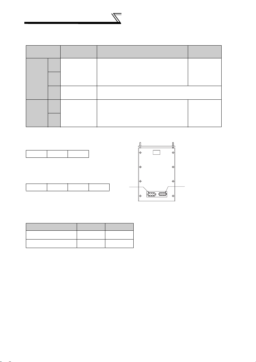
• Control circuit terminal layout
MSG
MSG
SD SD SD
AB
SD
Jumper
RES
BUE
PC
C
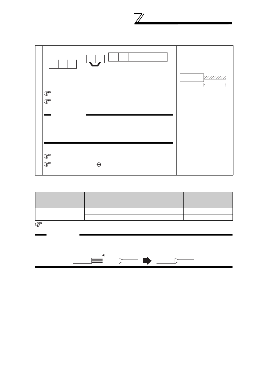
Loosen the terminal screw and insert the cable into the
terminal.
Screw size : M3
Tightening torque : 0.5N
•m to 0.6N•m
CAUTION
Undertightening can cause cable disconnection
or malfunction. Overtightening can cause a
short circuit or malfunction due to damage to
the screw or unit.
Control circuit terminal block
WIRING
Cable stripping size
6mm
Wire the stripped cable
after twisting it to
prevent it from
becoming loose.
In addition, do not
solder it.*
Cable size : 0.3mm
2
to 0.75mm
2
Screwdriver : Small flat-blade screwdriver
(Tip thickness : 0.4mm / tip width : 2.5mm)
* Information on bar terminals
Introduced products (as of June, 2006) : Phoenix Contact Co.,Ltd.
Terminal Screw Size
M3
Bar terminal crimping tool: CRIMPFOX ZA3 (Phoenix Contact Co., Ltd.)
Bar Terminal Model
(with insulation
sleeve)
Al 0.5-6WH A 0.5-6 0.3 to 0.5
Al 0.75-6GY A 0.75-6 0.5 to 0.75
Bar Terminal Model
(without insulation
sleeve)
Cable Size (mm2)
CAUTION
When using the bar terminal (without insulation sleeve), use care so that the twisted
wires do not come out.
7

WIRING
• Changing the control logic
The input signals are set to sink
logic when shipped from the
factory.
To change the control logic, the
jumper connector under the control
panel must be moved to the other
position.
• Change the jumper connector in
the sink logic position to source
logic position using tweezers, a
pair of long-nose pliers etc.
Change the jumper connector
position before switching power
on.
CAUTION
• Fully make sure that the front cover has been reinstalled securely.
• The front cover is fitted with the capacity plate and the brake unit with the
rating plate. Before reinstalling the front cover, check the serial numbers to
ensure that the cover removed is reinstalled to the brake unit from where it
was removed.
• The sink-source logic change-over jumper connector must be fitted in only
one of those positions. If it is fitted in both positions at the same time, the
brake unit may be damaged.
8
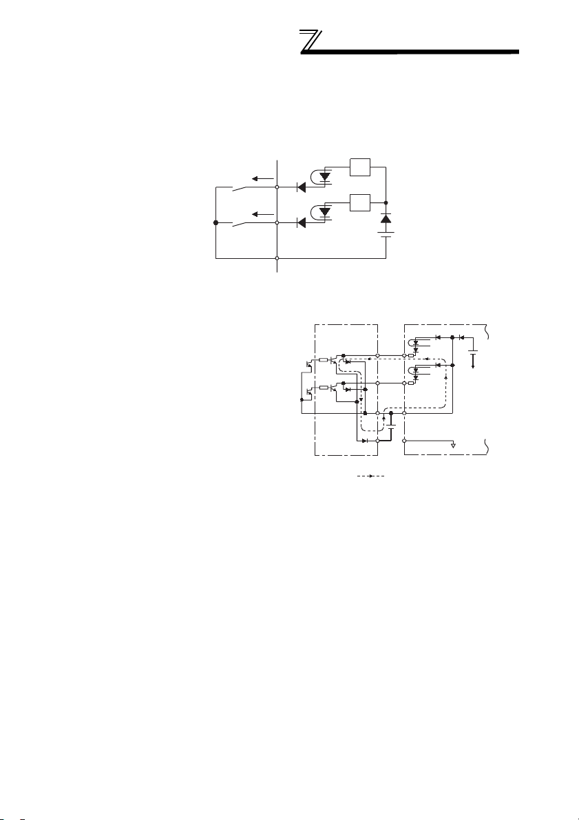
1) Sink logic type
• In sink logic, a signal switches on when a current flows from the
corresponding signal input terminal.
Terminal SD is common to the contact input signals.
WIRING
Power supply
• Connecting a positive terminal of
the external power supply for
transistor output to terminal PC
prevents a malfunction caused by
undesirable currents. (Do not
connect terminal SD of the brake
unit with terminal 0V of the external
power supply.)
BUE
RES
SD
R
R
AY40 type
transistor
output unit
1
2
RES
9
10
BUE
PC
SD
24VDC
Current flow
Brake unit
24VDC
(SD)
9
WIRING
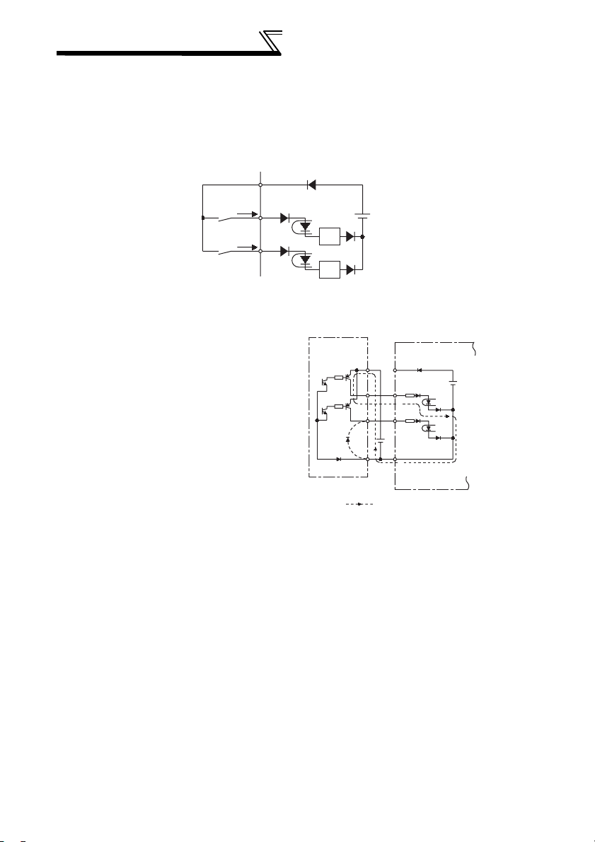
2) Source logic type
• In this logic, a signal switches on when a current flows into the
corresponding signal input terminal.
Terminal PC is common to the contact input signals.
PC
Power
supply
BUE
• Connecting a 0V terminal of the
external power supply for transistor
output to terminal SD prevents a
malfunction caused by undesirable
currents.
RES
R
R
AY80 type
transistor
output unit
9
1
2
10
Current flow
Brake unit
PC
BUE
RES
SD
24VDC
24VDC
(SD)
10
3.1.2 Resistor unit
(1) FR-BR-(H)
WIRING
Terminal
Symbol
Main
circuit
Control
circuit
• Terminal arrangement
Terminal Name Description Rating
P
Resistor unit
input resistance
PR
TH1
Alarm output
TH2
terminal
Connect to terminal P and PR of the brake
unit.
Output signal indicates resistor overheart
Resistor unit input terminal
PR P
TB1
Control circuit terminal block
arrangement
TH1 TH2
TB2
• Terminal screw size
Model TB1 TB2
FR-BR-15K
FR-BR-30K
200V
FR-BR-55K
FR-BR-H15K
FR-BR-H30K
400V
FR-BR-H55K M5 M3
M4 M3
M5 M3
M6 M3
M3 M3
M4 M3
---
1NC contact
110VAC, 5A
220VAC, 3A
<FR-BR resistor unit>
TB2
TB1
11
WIRING
(2) MT-BR5
Terminal
Symbol
Main
circuit
Control
circuit
• Terminal arrangement
Terminal Name Description Rating
P
Resistor unit
input terminal
PR
E
Earth terminal
TH1
Alarm output
terminal
TH2
Connect to terminal P and PR of the
brake unit.
For earthing (grounding) of the resistor unit. Must be
earthed (grounded).
Output signal indicates resistor
overheart.
Resistor unit input terminal
PPR
TB1
Control circuit terminal block
arrangement
TH1 TH2 E
TB2
• Terminal screw size (MT-BR5)
<MT-BR5 resistor unit>
NP
TB1
---
1 NO contact,
110VAC, 5A
220VAC, 3A
TB2
Model TB1 TB2
MT-BR5-55K M6 M4
MT-BR5-H75K M6 M4
12

3.2 Combinations of Brake Resistors for Brake
Unit and Used Wires
WIRING
Brake Unit Type
FR-BU2-1.5K
FR-BU2-3.7K
FR-BU2-7.5K
FR-BU2-15K
200V class
FR-BU2-30K
FR-BU2-55K
FR-BU2-H7.5K
FR-BU2-H15K
FR-BU2-H30K
400V class
FR-BU2-H55K FR-BR-H55K 5.5
FR-BU2-H75K
Brake Resistor, Resistor
Unit Type
GZG 300W-50Ω (one)
GRZG 200-10Ω (three in series)
GRZG 300-5Ω (four in series) 3.5
GRZG 400-2Ω (six in series)
FR-BR-15K
FR-BR-30K 5.5
FR-BR-55K
MT-BR5-55K
GRZG 200-10Ω (six in series) 2
GRZG 300-5Ω (eight in series)
FR-BR-H15K
GRZG 400-2Ω (twelve in series)
FR-BR-H30K
MT-BR5-H75K 14
Cable Size (mm2)
2
2
3.5
14
3.5
3.5
13
 Loading...