

Mitsubishi FR-ABR-3.7K, FR-ABR-0.4K, FR-ABR-5.5K, FR-ABR-7.5K, FR-ABR-11K Instruction Manual
...
TRANSISTORIZED INVERTER
INSTRUCTION MANUAL
HIGH-DUTY BRAKE RESISTOR
FR-ABR-(H)0.4K to 15K
F
Thank you for choosing the Mitsubishi transistorized inverter option
unit.
This instruction manual gives handling information and precautions for
use of this equipment.
Incorrect handling might cause an unexpected fault. Before using the
equipment, please read this manual carefully to use the equipment to
its optimum.
Please forward this instruction manual to the end user.
Safety Instructions
Do not attempt to install, operate, maintain or inspect this product
until you have read through this instruction manual and appended
documents carefully and can use the equipment correctly.
Do not use this product until you have a full knowledge of the
equipment, safety information and instructions.
In this manual, the safety instruction levels are classified into
"WARNING" and "CAUTION".
Denotes that incorrect handling may cause
WARNING
CAUTION
Note that even the level may lead to a serious
consequence under some circumstances. Please follow the
instructions of both levels as they are important to personnel safety.
hazardous conditions, resulting in death or
severe injury.
Denotes that incorrect handling may cause
hazardous conditions, resulting in medium or
slight injury, or may cause physical damage only.
CAUTION
SAFETY INSTRUCTIONS
1. Electric Shock Prevention
WARNING
• Before starting wiring or inspection, switch power off, wait for
more than 10 minutes, and check for no residual voltage with a
meter etc.
• Any person who is involved in the wiring or inspection of this
equipment should be fully competent to do the work.
A-1
2. Fire Prevention
CAUTION
• Mount the brake resistor on a non-combustible surface. Installing
it directly on or near a combustible surface could cause a fire.
• Use the alarm signal to switch power off. A failure to do so can
overheat the brake resistor due to a brake transistor failure etc.,
causing a fire.
3. Injury Prevention
CAUTION
• Ensure that the cables are connected to the correct terminals.
Otherwise, damage, etc. may occur.
• While power is on or for some time after power-off, do not touch
the brake resistor as it is hot. Touching it can cause burns.
4. Additional Instructions
Also note the following points to prevent an accidental failure, injury,
electric shock, etc.:
(1) Transportation and installation
CAUTION
• Transport products in a correct manner according to their weights.
Not doing so can cause injury.
• Install the product in a place secure enough to withstand its weight
according to the instruction manual.
(2) Usage
WARNING
• Do not modify the equipment.
(3) Disposal
CAUTION
• Dispose of this product as general industrial waste.
(4) General instructions
Many of the diagrams and drawings in this instruction manual show
the inverter without a cover, or partially open. Never run the inverter
like this. Always replace the cover and follow the instruction manual
when operating the inverter.
A-2

INSTALLATION INSTRUCTIONS FOR COMPLIANCE WITH UL
Install the FR-ABR brake resistors as follows:
• The resistor may be mounted horizontally or vertically, depending on a
suitable surface location.
• When the resistor is mounted externally to the enclosure housing the
inverter, install a solid Type 1 enclosure at least 8 times the volume size
of the resistor that incorporates mesh or perforated steel type ventilation
openings at each end of the resistor. Note, the vent openings shall not be
greater than 10 mm diameter.
• Secure the enclosure to a non-combustible surface only, such as metal or
concrete.
• Mount the resistor inside the Type 1 enclosure and wire it in accordance
with the NEC for North America installations or any other local codes.
Note, when the resistor and inverter are mounted together within a suitable
enclosure, the mesh covering is not required. Please take care that the
Inverter unit / resistor internal enclosure ambient does not exceed 50 deg. C.
Enclosure surface presents a possible burn hazard. After installation, the
following marking in minimum 3 mm (1/8 in.) sized lettering shall be provided
on the enclosure where visible:
CAUTION : HOT SURFACE. TO REDUCE RISK OF BURN - DO NOT TOUCH.
A-3
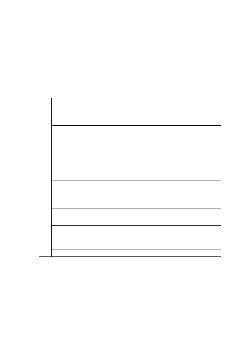
1. UNPACKING AND CHECKING THE MODEL AND APPLICABLE INVERTERS
Take the brake resistor out of the package and confirm that the product is
as you ordered and intact.
The FR-ABR Series brake resistors are a UL Listed Accessory for use
only with the following inverter models:
High-Duty Brake Resistor Model Applicable Inverter Models
FR-A520-0.4K(-**)
FR-ABR-0.4K
FR-ABR-0.75K
FR-ABR-2.2K
200V Class
FR-ABR-3.7K
FR-ABR-5.5K
FR-ABR-7.5K
FR-ABR-11K FR-V520-11K(-**)
FR-ABR-15K FR-V520-15K(-**)
Note : ** indicates alpha numeric combination.
FR-E520-0.4K(C)(-**), FR-E520S-0.4K(-**),
FR-E510W-0.4K(-**)
FR-A024-0.4K(-**)
FR-S520E-0.4K(-**)
FR-A520-0.75K(-**)
FR-E520-0.75K(C)(-**), FR-E520S-0.75K(-**),
FR-E510W-0.75K(-**)
FR-A024-0.75K(-**)
FR-S520E-0.75K(-**)
FR-A520-1.5K(-**), FR-A520-2.2K(-**)
FR-E520-1.5K(C)(-**), FR-E520-2.2K(C)(-**)
FR-V520-1.5K(-**), FR-V520-2.2K(-**)
FR-A024-1.5K(-**), FR-A024-2.2K(-**)
FR-S520E-1.5K(-**), FR-S520E-2.2K(-**)
FR-A520-3.7K(-**)
FR-E520-3.7K(C)(-**)
FR-V520-3.7K(-**)
FR-A024-3.7K(-**)
FR-S520E-3.7K(-**)
FR-A520-5.5K(-**)
FR-E520-5.5K(C)(-**)
FR-V520-5.5K(-**)
FR-A520-7.5K(-**)
FR-E520-7.5K(C)(-**)
FR-V520-7.5K(-**)
1
 Loading...