

Page 1

INVERTER
Control terminal option
FR-A8TR
INSTRUCTION MANUAL
Screw terminal block
PRE-OPERATION INSTRUCTIONS
INSTALLATION
1
2
Page 2
Thank you for choosing this Mitsubishi inverter control terminal option.
WARNING
CAUTION
CAUTION
This Instruction Manual provides handling information and precautions for use of the equipment. Incorrect handling might cause an unexpected
fault. Before using this product, always read this Instruction Manual carefully to use this product correctly.
Please forward this Instruction Manual to the end user.
Safety instructions
Do not attempt to install, operate, maintain or inspect the product until you have read through this Instruction Manual and supplementary
documents carefully and can use the equipment correctly. Do not use this product until you have a full knowledge of the equipment, safety
information and instructions. In this Instruction Manual, the safety instruction levels are classified into "WARNING" and "CAUTION".
Note that even the level may lead to a serious consequence depending on conditions. Be sure to follow the
instructions of both levels as they are critical to personnel safety.
Electric Shock Prevention
Incorrect handling may cause hazardous conditions, resulting in death or severe injury.
Incorrect handling may cause hazardous conditions, resulting in medium or slight injury, or may cause only
material damage.
WARNING
Do not remove the front cover or the wiring cover while the inverter power is ON. Do not operate the inverter with any cover or wiring cover removed, as accidental
contact with exposed high-voltage terminals and internal components may occur, resulting in an electrical shock.
Even if power is OFF, do not remove the front cover except for wiring or periodic inspection as you may accidentally touch the charged inverter circuits and get an
electric shock.
Before wiring or inspection, LED indication of the inverter unit operation panel must be switched OFF. Any person who is involved in wiring or inspection shall wait
for 10 minutes or longer after power OFF and check that there are no residual voltage using a tester or the like. The capacitor is charged with high voltage for some
time after power OFF, and it is dangerous.
Any person who is involved in wiring or inspection of this equipment shall be fully competent to do the work.
The control terminal option must be installed before wiring. Otherwise you may get an electric shock or be injured.
Do not touch the control terminal option or handle the cables with wet hands. Doing so may cause an electric shock.
Do not subject the cables to scratches, excessive stress, heavy loads or pinching. Doing so may cause an electric shock.
Injury Prevention
CAUTION
The voltage applied to each terminal must be the ones specified in the Instruction Manual. Otherwise a burst, damage, etc. may occur.
The cables must be connected to the correct terminals. Otherwise a burst, damage, etc. may occur.
The polarity (+ and -) must be correct. Otherwise a burst or damage may occur.
While power is ON or for some time after power OFF, do not touch the inverter as it will be extremely hot. Doing so may cause a burn.
2
Page 3
Additional Instructions
The following instructions must be also followed. If the product is handled incorrectly, it may cause unexpected fault, an injury, or an electric
shock.
CAUTION
Transportation and installation
Do not install or operate the control terminal option if it is damaged or has parts missing.
Do not stand or rest heavy objects on the product.
The mounting orientation must be correct.
Foreign conductive objects must be prevented from entering the inverter. That includes screws and metal fragments or other flammable substance such as oil.
If halogen-based materials (fluorine, chlorine, bromine, iodine, etc.) infiltrate into a Mitsubishi product, the product will be damaged. Halogen-based materials are
often included in fumigant, which is used to sterilize or disinfest wooden packages. When packaging, prevent residual fumigant components from being infiltrated
into Mitsubishi products, or use an alternative sterilization or disinfection method (heat disinfection, etc.) for packaging. Sterilization of disinfection of wooden
package should also be performed before packing a product.
Test operation
Before starting operation, each parameter must be confirmed and adjusted. Failure to do so may cause some machines to make unexpected motions.
WARNING
Usage
Do not modify the equipment.
Do not perform parts removal which is not instructed in this manual. Doing so may lead to fault or damage of the product.
CAUTION
Usage
As all parameters return to their initial values after the Parameter clear or All parameter clear is performed, the parameters must be set again as required before the
operation is started.
Static electricity in your body must be discharged before you touch the product.
Maintenance, inspection and parts replacement
Do not carry out a megger (insulation resistance) test.
Disposal
The product must be treated as industrial waste.
For clarity purpose, illustrations in this Instruction Manual may be drawn with covers or safety guards removed. Ensure all covers and safety guards are properly
General instruction
installed prior to starting operation.
3
Page 4

─ CONTENTS ─
1 PRE-OPERATION INSTRUCTIONS 5
1.1 Unpacking and product confirmation............................................................................................................................5
1.1.1 Product confirmation............................................................................................................................................................. 5
1.1.2 Component names................................................................................................................................................................6
1.1.3 Terminal layout ..................................................................................................................................................................... 7
1.1.4 Control logic switchover........................................................................................................................................................ 8
1.2 Restrictions for the FR-A8TR .........................................................................................................................................9
2 INSTALLATION 10
2.1 Pre-installation instructions .........................................................................................................................................10
2.2 Installation procedure ................................................................................................................................................... 10
2.3 Precautions for removal and reinstallation of the control circuit terminal block....................................................12
APPENDIX 13
4
Page 5
1 PRE-OPERATION INSTRUCTIONS
1.1 Unpacking and product confirmation
Take the control terminal option out of the package, check the product name, and confirm that the product is as you ordered
and intact.
The product is a control terminal option for the FR-A800/FR-F800 series. (This option is not supported on the Ethernet
communication type inverters.)
1.1.1 Product confirmation
Check the enclosed items.
Control terminal option
........................................................................ 1
1
PRE-OPERATION INSTRUCTIONS
5
Page 6

1.1.2 Component names
(a)
(c)
(d)
(b)
(e)
Symbol Name Description
a Mounting screw Fixes the option to the inverter. 10
b Terminal block Connect signal cables. 7
c Connector Connected to the control circuit connection connector of the inverter. 10
d Control logic switchover jumper connector Switches the control logic (sink logic or source logic). 8
e Terminal block cover Install this cover after wiring. ―
6
PRE-OPERATION INSTRUCTIONS
Refer to
page
Page 7

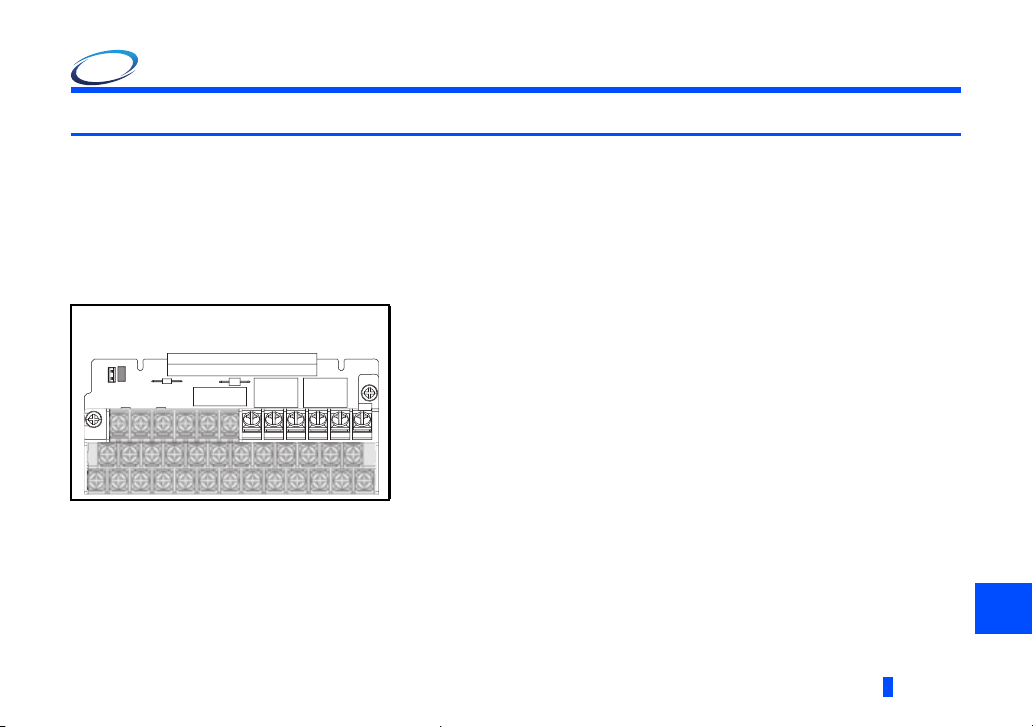
1.1.3 Terminal layout
NOTE
Terminal screw size: M3.5
Tightening torque: 1.2 N m
Recommended cable gauge: 0.75 mm
2
5PCCS
JOG
SD
SDSDFUOL
IPF
SU
RUN
SE
210AM
F/CSTRSTFRESMRS
RTRHRMRL
C2 14
10E+24
STOP
AUB2A2C1B1A1
• The inverter cover may not fit properly when using cables whose gauge is 1.25 mm2 or larger, or when using many
cables, and this could cause a contact fault of the operation panel.
• For the details of the terminal functions and specifications of the inverter, refer to the Instruction Manual (Detailed) of
the inverter.
PRE-OPERATION INSTRUCTIONS
1
7
Page 8

1.1.4 Control logic switchover
For sink logic
SOURCE
SINK
Jumper connector
Switch the control logic of input signals as necessary.
To change the control logic, change the jumper connector position on the control circuit board.
Connect the jumper connector to the connector pin of the desired control logic.
(For the details, refer to the Instruction Manual of the inverter.)
8
PRE-OPERATION INSTRUCTIONS
Page 9

1.2 Restrictions for the FR-A8TR
As compared with the standard control circuit terminal block, the FR-A8TR has the following restrictions.
• When the plug-in option FR-A8NS is used, terminals +24, 10E, 4, STOP, and AU of the FR-A8TR cannot be used.
• Because the height is restricted, two wires cannot be wired to upper-row terminals (except for terminals A1, B1, C1, A2, B2,
and C2) and middle-row terminals on the terminal block.
• The safety stop function is not available.
• For the connection to the terminal 1, use a screwdriver with a diameter of 4 mm or less. To avoid contact with the front cover
fixing area, put the screwdriver upright relative to the terminal screw surface.
4 mm or less
φ
Avoid contact with
Keep the screwdriver
upright relative to the
terminal screw surface
while rotating the
screwdriver.
the front cover
fixing area.
1
PRE-OPERATION INSTRUCTIONS
9
Page 10

2 INSTALLATION
2.1 Pre-installation instructions
Check that the inverter's input power and the control circuit power are both OFF.
CAUTION
Do not mount or remove the control terminal option while the input power is ON. Doing so may damage the inverter or the
control terminal option.
To avoid damage due to static electricity, static electricity in your body must be discharged before you touch the product.
2.2 Installation procedure
(1) Loosen the two mounting screws at the both side of the standard control circuit terminal block. (These screws cannot be
removed.)
Slide down the control circuit terminal block to remove it.
Loosen the screws
10
INSTALLATION
Page 11

(2) Be careful not to bend the pins of the inverter's control circuit connector, install the control terminal option and fix it with the
Fix it with
the screws
mounting screws for the control terminal option. (Tightening torque: 0.33 to 0.4 N•m)
INSTALLATION
2
11
Page 12

2.3 Precautions for removal and reinstallation of the control circuit
NOTE
terminal block
The following are the precautions to remove or reinstall the control circuit terminal block.
Observe the following for proper handling to avoid malfunctions or failures of the inverter.
• To remove or reinstall the control circuit terminal block, keep it upright so that it is parallel with the inverter.
• To install the control circuit terminal block, slide it upward so that the groove on the terminal block fits over the tongue on the
inverter. Adjust the terminal block position for alignment with the screw fixing bases.
• Check that the terminal block is parallel with the inverter and the pins of the inverter's control circuit connector are not bent.
After checking the proper connection, fix the terminal block with two screws.
Fit the groove over the tongue.
A
Insert the terminal
block parallel into the
inverter.
• Do not tilt the terminal block while tightening the screws or removing it from the inverter. (Otherwise, a stress applied
to the control circuit terminal block or the control circuit connector may cause damage to them.)
12
INSTALLATION
Fasten the screws.
Inverter's control circuit
Control circuit terminal block
connector
Control circuit terminal block
Inverter's control circuit
connector
View from A side
Page 13

APPENDIX
Restricted Use of Hazardous Substances in Electronic and Electrical Products
The mark of restricted use of hazardous substances in electronic and electrical products is applied to the product as follows
based on the “Management Methods for the Restriction of the Use of Hazardous Substances in Electrical and Electronic
Products” of the People's Republic of China.
电器电子产品有害物质限制使用标识要求
环境保护使用期限标识
本产品中所含有的有害物质的名称、含量、含有部件如下表所示。
• 产品中所含有害物质的名称及含量
部件名称
电路板组件 (
如电阻、电容、集成电路、
金属壳体、金属部件
树脂壳体、树脂部件
螺丝、电线
上表依据SJ/T11364的规定编制。
○:表示该有害物质在该部件所有均质材料中的含量均在GB/T26572规定的限量要求以下。
×:表示该有害物质在该部件的至少一种均质材料中的含量超出GB/T26572规定的限量要求。
包括印刷电路板及其构成的零部件,
连接器等)、电子部件
即使表中记载为 ×,根据产品型号,也可能会有 有害物质的含量为限制值以下的情况。
根据产品型号,一部分部件可能不包含在产品 中。
铅(Pb) 汞(Hg) 镉(Cd) 六价铬(Cr(VI)) 多溴联苯(PBB) 多溴二苯醚(PBDE)
有害物质
APPENDIX
13
Page 14

MEMO
14
IB(NA)-0600566ENG-B
Page 15

REVISIONS
*The manual number is given on the bottom left of the back cover.
Print date *Manual number Revision
Dec. 2014 IB(NA)-0600566ENG-A First edition
Dec. 2017 IB(NA)-0600566ENG-B
Addition
• Precautions for removal and reinstallation of the control circuit terminal block
• Restricted Use of Hazardous Substances in Electronic and Electrical Products
15
Page 16

INVERTER
HEAD OFFICE: TOKYO BUILDING 2-7-3, MARUNOUCHI, CHIYODA-KU, TOKYO 100-8310, JAPAN
IB(NA)-0600566ENG-B(1712) MEE
Printed in Japan Specifications subject to change without notice.
 Loading...