

Mitsubishi Electric FR-A8NP Instruction Manual

INVERTER
Plug-in option
PRE-OPERATION INSTRUCTIONS
INSTALLATION
1
2
FR-A8NP
INSTRUCTION MANUAL
PROFIBUS-DP
communication function
WIRING
INVERTER SETTING
FUNCTIONS
PROFIBUS DEVICE DATA
PPO TYPE SUPPORT
SPECIFICATION
PPO TYPE NON-SUPPORT
SPECIFICATION
TROUBLESHOOTING
3
4
5
6
7
8
9
Thank you for choosing this Mitsubishi inverter plug-in option.
Warning
Caution
Caution
This Instruction Manual provides handling information and precautions for use of this product. Incorrect handling might cause an unexpected
fault. Before using this product, always read this Instruction Manual carefully to use this product correctly.
Please forward this Instruction Manual to the end user.
Safety instructions
Do not attempt to install, operate, maintain or inspect the product until you have read through this Instruction Manual and appended
documents carefully and can use the equipment correctly. Do not use this product until you have a full knowledge of the equipment, safety
information and instructions. In this Instruction Manual, the safety instruction levels are classified into "Warning" and "Caution".
The level may even lead to a serious consequence according to conditions. Both instruction levels must be followed
because these are important to personal safety.
Electric shock prevention
Incorrect handling may cause hazardous conditions, resulting in death or severe injury.
Incorrect handling may cause hazardous conditions, resulting in medium or slight injury, or may cause only material
damage.
Warning
While the inverter power is ON, do not open the front cover or the wiring cover. Do not run the inverter with the front cover or the wiring cover removed. Otherwise
you may access the exposed high voltage terminals or the charging part of the circuitry and get an electric shock.
Do not remove the inverter front cover even if the power supply is disconnected. The only exception for this would be when performing wiring and periodic
inspection. You may accidentally touch the charged inverter circuits and get an electric shock.
Before wiring or inspection, LED indication of the inverter unit operation panel must be switched OFF. Any person who is involved in wiring or inspection shall wait
for at least 10 minutes after the power supply has been switched OFF and check that there is no residual voltage using a tester or the like. For some time after the
power-OFF, a high voltage remains in the smoothing capacitor, and it is dangerous.
Any person who is involved in wiring or inspection of this equipment shall be fully competent to do the work.
The plug-in option must be installed before wiring. Otherwise you may get an electric shock or be injured.
Do not touch the plug-in option or handle the cables with wet hands. Otherwise you may get an electric shock.
Do not subject the cables to scratches, excessive stress, heavy loads or pinching. Otherwise you may get an electric shock.
Injury prevention
Caution
The voltage applied to each terminal must be the ones specified in the Instruction Manual. Otherwise a burst, damage, etc. may occur.
The cables must be connected to the correct terminals. Otherwise a burst, damage, etc. may occur.
The polarity (+ and -) must be correct. Otherwise a burst or damage may occur.
While power is ON or for some time after power OFF, do not touch the inverter as it will be extremely hot. Touching these devices may cause a burn.
1
Additional instructions
The following instructions must be also followed. If the product is handled incorrectly, it may cause unexpected fault, an injury, or an electric
shock.
Caution
Transportation and mounting
Do not install or operate the plug-in option if it is damaged or has parts missing.
Do not stand or rest heavy objects on the product.
The mounting orientation must be correct.
Foreign conductive objects must be prevented from entering the inverter. That includes screws and metal fragments or other flammable substance such as oil.
If halogen-based materials (fluorine, chlorine, bromine, iodine, etc.) infiltrate into a Mitsubishi product, the product will be damaged. Halogen-based materials are
often included in fumigant, which is used to sterilize or disinfest wooden packages. When packaging, prevent residual fumigant components from being infiltrated
into Mitsubishi products, or use an alternative sterilization or disinfection method (heat disinfection, etc.) for packaging. Sterilization of disinfection of wooden
package should also be performed before packaging the product.
Trial run
Before starting operation, each parameter mu st be confirmed and adjusted. A failure to do so may cause some machines to make unexpected motions.
Warning
Usage
Do not modify the equipment.
Do not perform parts removal which is not instructed in this manual. Doing so may lead to fa ult or damage of the product.
Caution
Usage
When parameter clear or all parameter clear is performed, the required parameters must be set again before starting operations. Because all parameters return to
their initial values.
To avoid damage due to static electricity, static electricity in your body must be discharged before you touch the product.
Maintenance, inspection and parts replacement
Do not carry out a megger (insulation resistance) test.
Disposal
The product must be treated as industrial waste.
Many of the diagrams and drawings in this Instruction Manual show the inverter without a cover or partially open for explanation. Never operate the inverter in this
manner. The cover must be reinstalled and the instructions in the Instruction Manual must be followed when operating the inver ter.
2
General instruction

─ CONTENTS ─
1 PRE-OPERATION INSTRUCTIONS 7
1.1 Unpacking and product confirmation............................................................................................................................7
1.2 Component names ..........................................................................................................................................................8
1.3 Specifications ..................................................................................................................................................................9
1.3.1 Inverter option specifications ................................................................................................................................................ 9
1.3.2 Communication specifications .............................................................................................................................................. 9
2 INSTALLATION 10
2.1 Pre-installation instructions .........................................................................................................................................10
2.2 Installation procedure ...................................................................................................................................................11
2.3 Node address switch setting ........................................................................................................................................ 15
3WIRING 16
3.1 Terminals........................................................................................................................................................................16
3.2 Wiring..............................................................................................................................................................................17
4 INVERTER SETTING 20
4.1 Parameter list .................................................................................................................................................................20
4.2 Operation mode setting ................................................................................................................................................22
4.2.1 Operation mode switching and communication startup mode (Pr.79, Pr.340).................................................................... 22
4.3 Operation at communication error occurrence ..........................................................................................................25
4.3.1 Operation selection at communication error occurrence (Pr.500 to Pr.502, Pr.779) .......................................................... 25
4.3.2 Fault and measures ............................................................................................................................................................ 29
4.4 Inverter reset ..................................................................................................................................................................30
5 FUNCTIONS 32
5.1 Output from the inverter to the network......................................................................................................................32
3

5.2 Input to the inverter from the network.........................................................................................................................33
6 PROFIBUS DEVICE DATA 34
6.1 Device data (GSD file) ...................................................................................................................................................34
6.2 Slave user parameter ....................................................................................................................................................39
7 PPO TYPE SUPPORT SPECIFICATION 40
7.1 PROFIBUS profiles ........................................................................................................................................................40
7.1.1 Setting the PROFIBUS format (Pr.1110) ............................................................................................................................ 40
7.2 ID definitions .................................................................................................................................................................. 42
7.3 Buffer memory configuration .......................................................................................................................................43
7.4 Buffer memory details...................................................................................................................................................45
7.5 Outline of PNU ...............................................................................................................................................................54
7.6 PROFIBUS PNU..............................................................................................................................................................55
7.6.1 Real-time monitor................................................................................................................................................................ 55
7.6.2 Parameter clear .................................................................................................................................................................. 56
7.6.3 Operation mode read/write ................................................................................................................................................. 56
7.6.4 Set frequency read..............................................................................................................................................................56
7.6.5 Terminal input read ............................................................................................................................................................. 57
7.6.6 Inverter reset....................................................................................................................................................................... 57
7.6.7 REF command assignment (available only when the extended format is selected) (only for the FR-A800 series)............ 57
7.6.8 STS monitor function (available only when the extended format is selected) (only for the FR-A800 series)...................... 59
7.6.9 Node address read ............................................................................................................................................................. 59
7.6.10 Faults history read .............................................................................................................................................................. 60
7.6.11 PNU list read....................................................................................................................................................................... 64
7.7 Standard parameters.....................................................................................................................................................65
7.8 PROFIBUS-DP communication function setting ........................................................................................................68
7.8.1 PROFIBUS communication command source setting (Pr.1109) (only for the FR-A800 series) ......................................... 68
7.8.2 Torque command / torque limit via PROFIBUS communication (Pr.804) (only for the FR-A800 series)............................69
7.8.3 Torque bias selection (Pr.840) (only for the FR-A800 series)............................................................................................. 70
7.8.4 Frequency command with sign (Pr.541) ............................................................................................................................. 71
4

8 PPO TYPE NON-SUPPORT SPECIFICATION 72
8.1 PROFIBUS profiles ........................................................................................................................................................72
8.2 ID definitions ..................................................................................................................................................................73
8.3 Buffer memory configuration .......................................................................................................................................74
8.4 Buffer memory details...................................................................................................................................................75
8.5 Outline of PNU ...............................................................................................................................................................79
8.6 PROFIBUS PNU (module type A5NP) ..........................................................................................................................80
8.6.1 Real-time monitor area (IND=H0000 (IND=H00, PP=H00)) ............................................................................................... 80
8.6.2 System environment variable (sev) area (IND = H01PP (IND = H01, PP = H00, H01))..................................................... 81
8.7 Standard parameters.....................................................................................................................................................85
8.7.1 Normal parameter area (IND = H0200 (IND = H02, PP = H00))......................................................................................... 85
8.7.2 Pr.900 to calibration parameter (frequency) area (IND=H0300 (IND=H03, PP=H00)) ....................................................... 86
8.7.3 Pr.900 to calibration parameter (%) area (IND=H0400 (IND=H04, PP=H00)).................................................................... 87
9 TROUBLESHOOTING 88
5

MEMO
6
1 PRE-OPERATION INSTRUCTIONS
X16
X1
ON
12
0
F
E
D
C
B
A
9
8
7
6
5
4
3
2
1
0
F
E
D
C
B
A
9
8
7
6
5
4
3
2
1
1.1 Unpacking and product confirmation
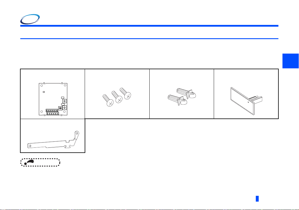
Take the plug-in option out of the package, check the product name, and confirm that the product is as you ordered and intact.
This product is a plug-in option for the FR-A800/F800 series inverter.
Product confirmation
Check the enclosed items.
Plug-in option
..............................................1
Earth plate
..................1 (Refer to page 12.)
NOTE
•PROFIBUS is a registered trademark of PROFIBUS User Organization.
Mounting screw (M3 8 mm)
..................3 (Refer to page 12.)
Spacer
..................2 (Refer to page 12.)
Communication option LED
display cover
..................1 (Refer to page 11.)
1
PRE-OPERATION INSTRUCTIONS
7
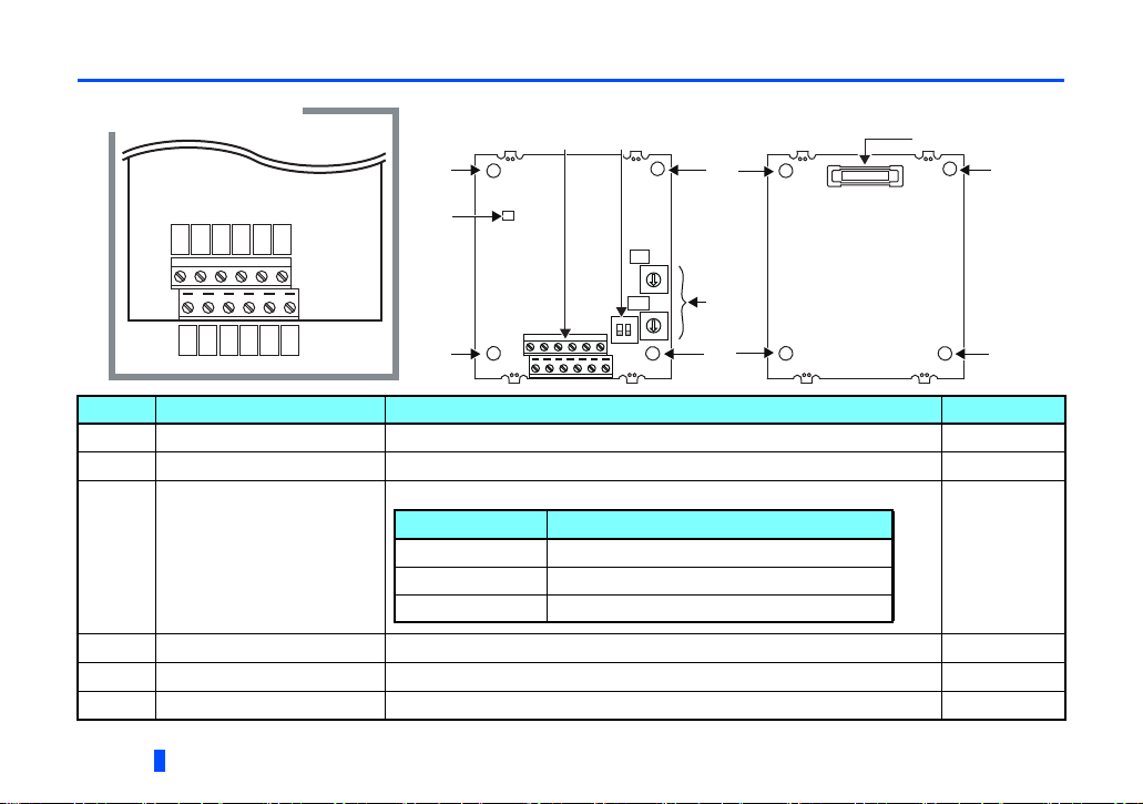
1.2 Component names
Front view
Rear view
(b) (e)
(c)
(f)
X1
ON
12
(a)
(a)
(a)
(a)
(a)
(a)
(d)
0
F
E
D
C
B
A
9
8
7
6
5
4
3
2
1
0
F
E
D
C
B
A
9
8
7
6
5
4
3
2
1
Pin assignment
D+
D-V-D-
CNTR
FG
V+
D+D-D+
V-
FG
(SW2)
(SW3)
X16
LED status Description
OFF Inverter power OFF
Red (ON) A communication error with the master occurred
Green (ON) During communication with the master
Symbol Name Description Refer to page
a Mounting hole Fixes the option to the inverter with screws, or installs spacers.
b Terminal block Connect the communication cable.
ON/OFF indicator of the LED indicates inverter operation status.
12
16
c Operation status (LED)
d Node address switch Set the inverter address within the range of H00 to H7D.
e Switch for manufacturer setting Do not change from initially-set status. (The switches 1 and 2 are both OFF.)
f Connector Connect to the inverter option connector.
8
PRE-OPERATION INSTRUCTIONS
—
15
—
12
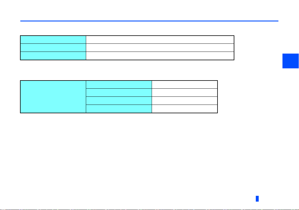
1.3 Specifications
1.3.1 Inverter option specifications
Typ e
Number of nodes occupied
Connection cable
Inverter plug-in option type
One inverter occupies one node.
Cable which supports 12.0 Mbps communication (EIA-485(RS-485) standard)
1.3.2 Communication specifications
Wiring length 1200 m or less
Communication speed
Wiring length 600 m or less
Wiring length 200 m or less
Wiring length 100 m or less
9600 bps, 19.2 Kbps, 93.75 Kbps
187.5 Kbps
500 Kbps, 1.5 Mbps
3.0 Mbps, 6.0 Mbps, 12.0 Mbps
PRE-OPERATION INSTRUCTIONS
1
9
2 INSTALLATION
2.1 Pre-installation instructions
Check that the inverter's input power and the control circuit power are both OFF.
Caution
With input power ON, do not install or remove the plug-in option. Otherwise, the inverter and plug-in option may be damaged.
To avoid damage due to static electricity, static electricity in your body must be discharged before you touch the product.
10
INSTALLATION
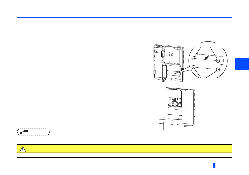
2.2 Installation procedure
Cut off with a nipper, etc.
Cut off with a nipper, etc.
Communication option LED display cover
Installing the communication option LED display cover
(1) Remove the inverter front cover. (Refer to Chapter 2 of the Instruction Manual (Detailed) of the inverter for details on how
to remove the front cover.)
Mount the cover for displaying the operation status indication LED for the communication option on the inverter front cover.
(2) Cut off hooks on the rear of the inverter front cover with nipper, etc. and
open the window for fitting the LED display cover.
(3) Fit the communication option LED display cover to the front side of the
front cover. Align the LED display cover with the LED position on the
circuit board of the option. Push the LED display cover until it is fixed with
the hooks.
NOTE
The protective structure (JEM1030) changes to the open type (IP00).
Take care not to hurt your hand and such with portions left by cutting hooks of the rear of the front cover.
Caution
2
INSTALLATION
11
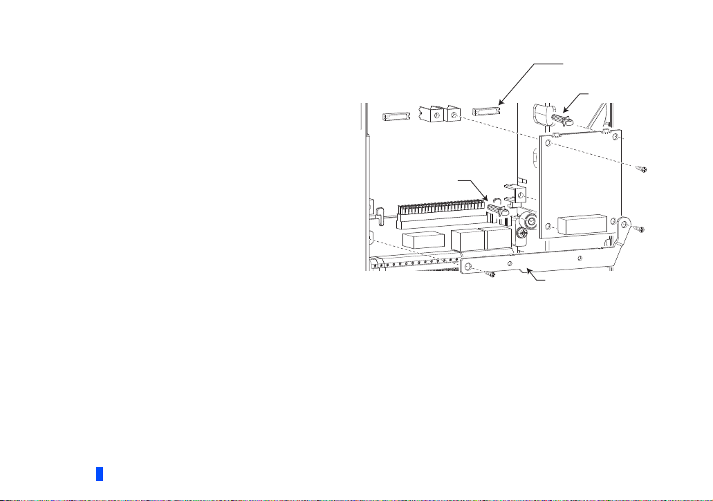
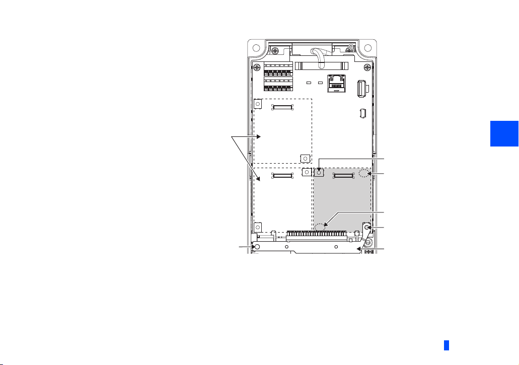
Installing the option
(1) For the two mounting holes (as shown in the next page)
that will not be tightened with mounting screws, insert
spacers.
(2) Fit the connector of the plug-in option to the guide of the
connector on the inverter unit side, and insert the plug-in
option as far as it goes. (Insert it to the inverter option
connector 1.)
(3) Fit the one location on the left of the earth plate (as shown
in the next page) securely to the inverter unit by screwing
in the supplied mounting screw. (tightening torque 0.33
N·m to 0.40 N·m)
(4) Fit the one location on the left of the plug-in option
securely to the inverter unit and the right of the plug-in
option to the inverter unit together with the earth plate by
screwing in the supplied mounting screws. (tightening
torque 0.33 N·m to 0.40 N·m) If the screw holes do not
line up, the connector may not be inserted deep enough.
Check the connector.
Inverter side
option connector
Spacer
Spacer
Earth plate
Example of installation to connector 1
12
INSTALLATION
2
Spacer
Spacer
Mounting screw
Do not insert the plug-in option to the connector 2 or 3.
Mounting screw
Connector 1Connector 2
Connector 3
Insertion positions for screws and spacers
Earth plate
Mounting screw
INSTALLATION
13
NOTE
• When mounting/removing the plug-in option, hold the sides of the option. Do not press on the parts on the option
circuit board. Stress applied to the parts by pressing, etc. may cause a failure.
• Caution must be applied to mounting screws falling off when removing and mounting the plug-in option.
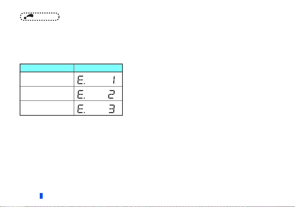
• When using this plug-in option, insert it to the inverter option connector 1. If it is inserted to the option connector 2 or 3,
the protective function (E.2 or E.3) is activated and the inverter will not operate.
Even if the option is inserted to the option connector 1, when the inverter cannot recognize that the option is mounted
due to improper installation, etc., the protective function (E.1) is activated.
Mounted position Fault indication
Option connector 1
Option connector 2
Option connector 3
• When removing the plug-in option, remove the two screws on the left and right, then pull it straight out. Pressure
applied to the connector and to the option board may break the option.
• Always attach the earth plate because a malfunction due to noises may occur without it.
14
INSTALLATION

2.3 Node address switch setting
X16
X1
0
1
2
3
4
5
6
7
8
9
A
B
C
D
E
F
0
1
2
3
4
5
6
7
8
9
A
B
C
D
E
F
(SW3)
(SW2)
0
1
2
3
4
5
6
7
8
9
A
B
C
D
E
F
0
1
2
3
4
5
6
7
8
9
A
B
C
D
E
F
Good
example
Bad
example
Set the node address between "H00" and "H7D" using the node address switches on the FR-A8NP board. (Refer to page 8.)
The setting is applied at the next power-ON.
Set the arrow () of the corresponding switches to a number or an alphabet to set a desired address.
• Setting example
Node address 1:
Set the "
(SW2) to "1".
" of X16 (SW3) to "0" and the " " of X1
NOTE
• Set the inverter node address before switching ON the inverter and do not change the setting while power is ON.
Otherwise you may get an electric shock.
• Set the node address switch to the switch number (alphabet) position correctly. If the switch is set between numbers,
normal data communication cannot be established.
• When the node address switches are set to any of H7E to HFF, the node address is recognized as H7D.
• The node addresses, H00, H01, H02, H7C, and H7D, may not be available for some master modules.
• You cannot set the same node address to other devices on the network. (Doing so disables proper communication.)
X1
X16
Node address 38 (H26):
(SW2)
Set the " " of X16 (SW3) to "2" and the " " of X1
9
8
A
7
6
B
C
5
4
D
3
(SW2) to "6".
E
2
F
1
0
(SW3)
9
8
A
7
6
B
C
5
4
D
3
E
2
F
1
0
INSTALLATION
2
15
3 WIRING
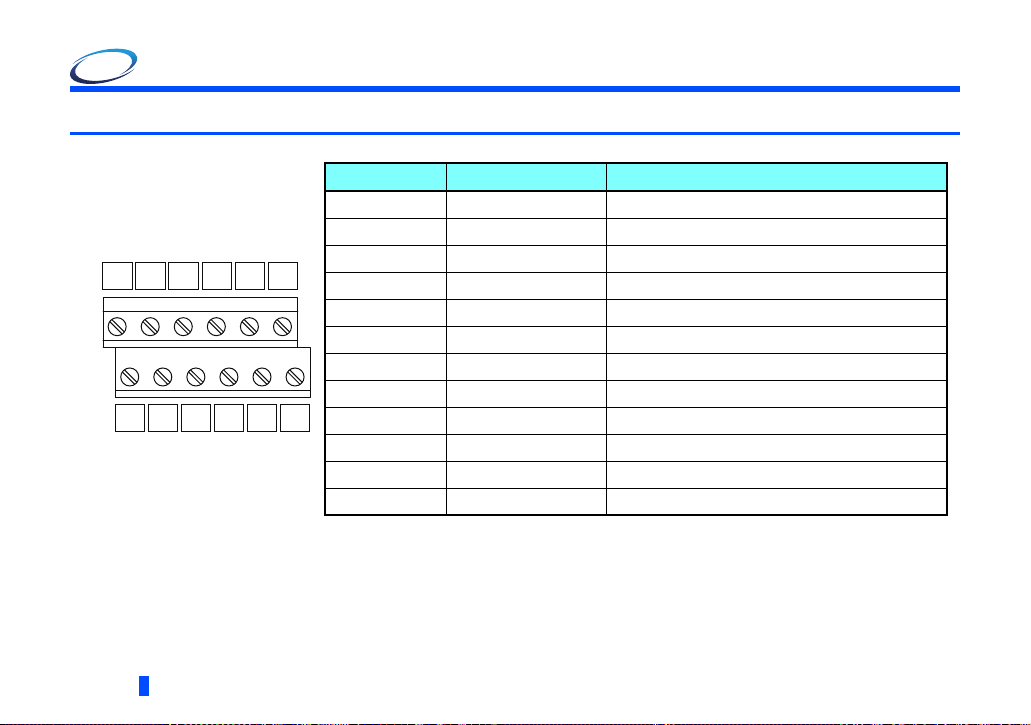
Ter min a l no . Terminal name Definition
1-A V+ (VP) Voltage output (approx. 5 V to V-)
1-B D+ (RXD/TXD-P) Sends and receives PROFIBUS signal+ (B-line)
2-A D+ (RXD/TXD-P)
Sends and receives PROFIBUS signal+ (B-line)
2-B D- (RXD/TXD-N) Sends and receives PROFIBUS signal- (A-line)
3-A D- (RXD/TXD-N)
Sends and receives PROFIBUS signal- (A-line)
3-B V- (DGND) GND of D+/D-
4-A D+ (RXD/TXD-P)
(To connect a terminating resistor)
4-B D- (RXD/TXD-N)
(To connect a terminating resistor)
5-A V- (DGND)
GND of D+/D-
5-B CNTR
Control signal (sending request from the inverter)
6-A FG (Connected to the earth of the inverter unit)
6-B FG (Connected to the earth of the inverter unit)
D+ D- V-
D-
CNTR
FG
V+ D+ D- D+ V- FG
123456A
123456B
3.1 Terminals
16
When connecting a terminating resistor, connect the terminating resistor to these terminals. (Refer to page 19)
It may not be necessary depending on the master used.
WIRING
3.2 Wiring
5 mm
Crumpled tip
Wires are not inserted
into the sleeve
Unstranded
wires
Damaged
WireWire
SleeveSleeve
0 to 0.5 mm0 to 0.5 mm
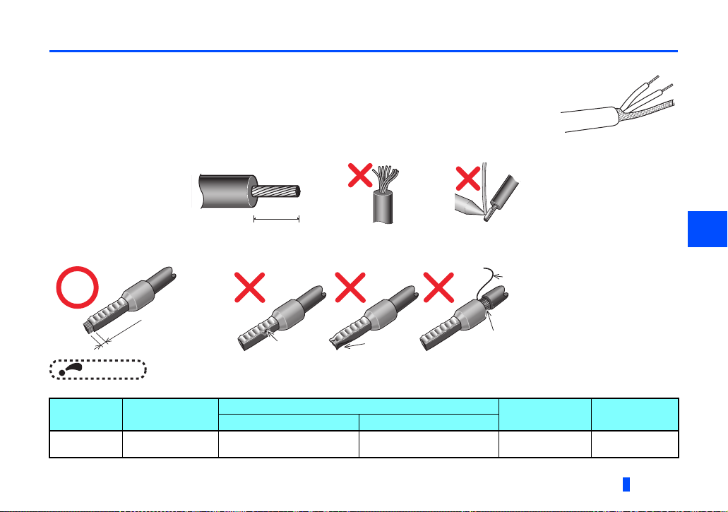
Use the network connection cable which supports 12.0 Mbps communication.
(1) Strip off the sheath of the PROFIBUS communication dedicated cable and wind wires and shield
cables to use.
Strip off the sheath for the below length. If the length of the sheath peeled is too long, a short circuit
may occur with neighboring wires. If the length is too short, wires might come off.
Wire the stripped cable after twisting it to prevent it from becoming loose. In addition, do not solder it.
Cable stripping length
Use a ferrule terminal as necessary.
When using the ferrule terminal, use care so that the twisted wires do not come out.
NOTE
• Ferrule terminal commercially available (as of February 2012. The product may be changed without notice.)
Ter mina l
screw size
M2 0.3 to 0.5 Al 0,5-6WH A 0,5-6
Wire size (mm2)
with insulation sleeve without insulation sleeve
Ferrule terminal model
Manufacturer
Phoenix Contact
Co.,Ltd.
Crimping tool
CRIMPFOX 6
WIRING
3
name
17
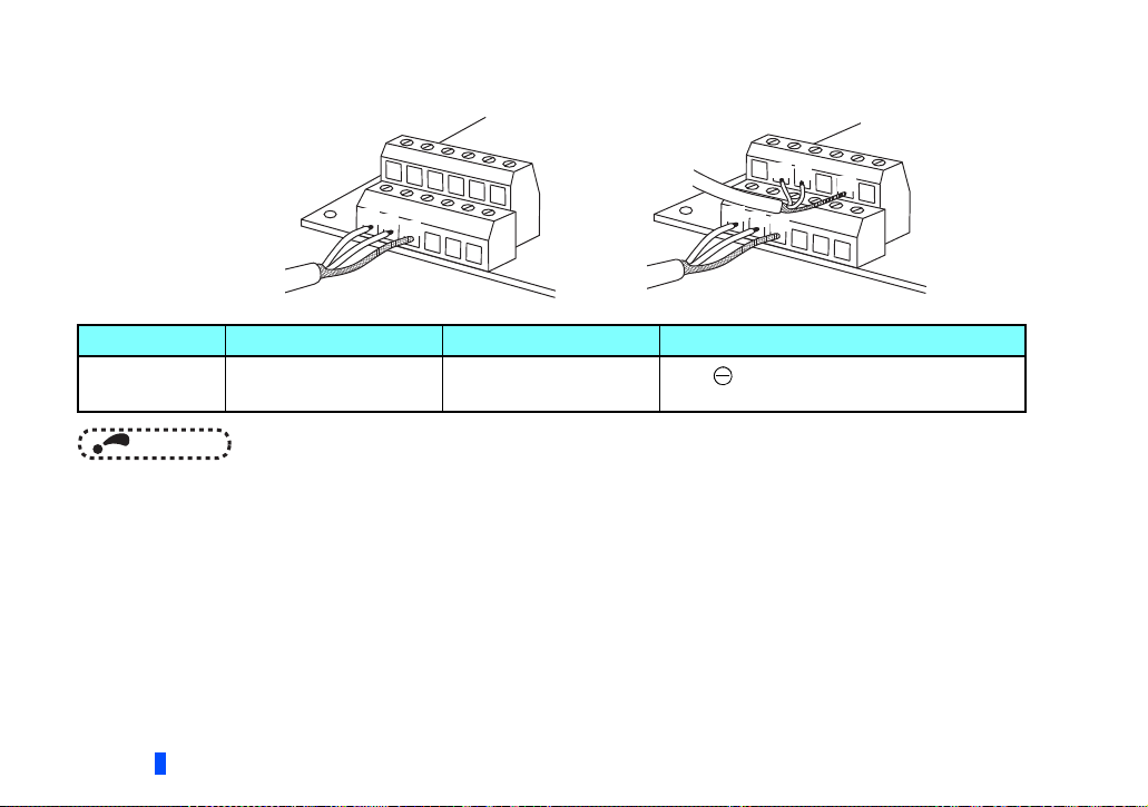
(2) Loosen the terminal screw and insert the cable into the terminal.
Tighten each cable with fixing screws to the recommended tightening torque.
<Cable connection example>
<Connection example of multiple inverters>
To next inverter
D+
D-
V-
D+
D-
D+
D-
V-
To master
Screw size Tightening torque Cable size Screwdriver
M2 0.22 N•m to 0.25 N•m
0.3 mm
2
to 0.75 mm
2
Small flat-blade screwdriver
(Tip thickness: 0.4 mm /tip width: 2.5 mm)
NOTE
• Undertightening can cause cable disconnection or malfunction. Overtightening can cause a short circuit or malfunction
due to damage to the screw or unit.
18
WIRING
V-
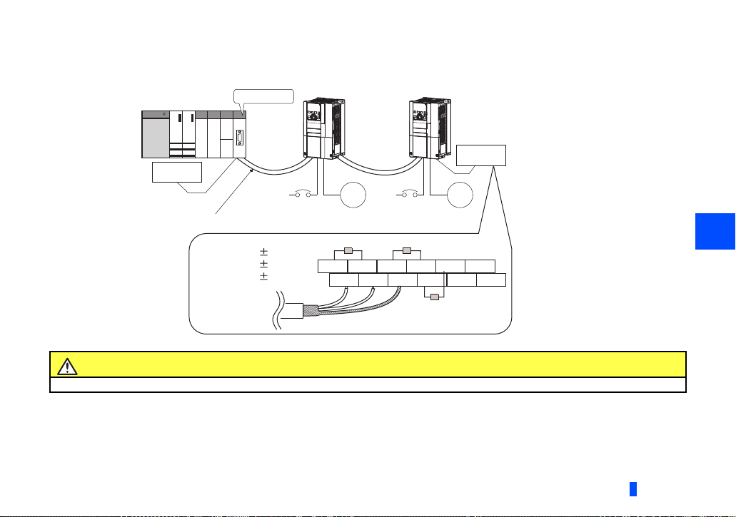
(3) Terminating resistor
Connect terminating resistors to the both ends of a network if the both ends are FR-A8NP-mounted inverters.
Connection example
Master station
PLC etc.
Terminating
resistor
Power
supply
PROFIBUS communication cable
R1=390Ω 2% 1/4W
R2=220Ω 2% 1/4W
R3=390Ω 2% 1/4W
Inverter
Motor Motor
R1 R2
V+ D+ D- D+D-V-
Power
supply
Inverter
Terminating
resistor
3
To other inverter
(node)
R3
Caution
After wiring, wire offcuts must not be left in the inverter. They may cause an error, failure or malfunction.
WIRING
19
4 INVERTER SETTING
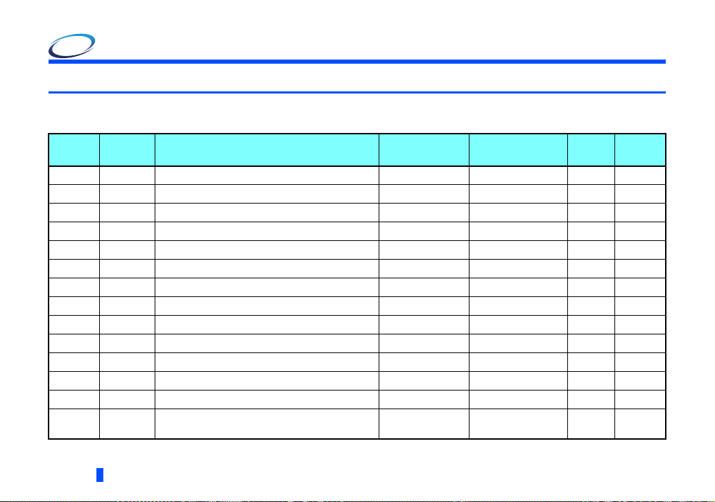
4.1 Parameter list
The following parameters are used for the communication option (FR-A8NP).
Set the values according to need.
Pr.
79 D000 Operation mode selection 0 to 4, 6, 7 1 0 22
338 D010 Communication operation command source 0, 1 1 0
339 D011 Communication speed command source 0, 1, 2 1 0
340 D001 Communication startup mode selection 0, 1, 2, 10, 12 1 0 22
342 N001 Communication EEPROM write selection 0, 1 1 0
349 N010 Communication reset selection 0, 1 1 0 31
N011 Communication error execution waiting time 0 to 999.8 s 0.1 s 0 s 25
500
N012 Communication error occurrence count display 0 1 0 26
501
502 N013 Stop mode selection at communication error 0 to 3 1 0 26
N100 Frequency command sign selection 0, 1 1 0 71
541
D012 NET mode operation command source selection 0, 1, 9999 1 9999
550
779 N014 Operation frequency during communication error 0 to 590 Hz, 9999 0.01 Hz 9999 26
D400 Torque command source selection 0, 1, 3 to 6 1 0 69
804
840
20
Pr.
group
G230
Torque bias selection
INVERTER SETTING
Name Setting range
0 to 3, 24, 25,
9999
Minimum setting
increments
1 9999 70
Initial
value
Refer to
page

Pr.
1109
1110
Pr.
group
G320
N190
Parameters which can be displayed when the plug-in option (FR-A8NP) is mounted.
Parameters which can be displayed when the plug-in option (FR-A8AP) is mounted.
The setting is applied after an inverter reset or power-ON.
For the parameter details, refer to the Instruction Manual (Detailed) of the inverter.
The setting is available only for the FR-A800 series.
PROFIBUS communication command source
selection
PROFIBUS format selection 0, 1 1 0 40
Name Setting range
0, 1, 10, 11, 20,
21, 100, 101, 110,
111, 120, 121,
1000, 1001, 1010,
1011, 1020, 1021,
1100, 1101, 1110,
1111, 1120 , 112 1
Minimum setting
increments
1068
Initial
value
Refer to
page
4
INVERTER SETTING
21

4.2 Operation mode setting
4.2.1 Operation mode switching and communication startup mode (Pr.79, Pr.340)
Operation mode switching conditions
Operation mode switching conditions
• The inverter is at a stop;
• Both the STF and STR signals are off; and
• The Pr.79 Operation mode selection setting is correct.
(Set with the operation panel of the inverter.)
Operation mode selection at power ON and at restoration from instantaneous power failure
The operation mode at power ON and at restoration from instantaneous power failure can be selected.
Set a value other than "0" in Pr.340 Communication startup mode selection to select the network operation mode.
After started in network operation mode, parameter write from the network is enabled.
NOTE
• Change of the Pr.340 setting is valid when powering on or resetting the inverter.
• Pr.340 can be changed with the operation panel independently of the operation mode.
• Ensure that the communication setting of the inverter is completed before setting Pr.340 "0".
• Refer to the Instruction Manual (Detailed) of the inverter for details of Pr.79, Pr.340.
22
INVERTER SETTING
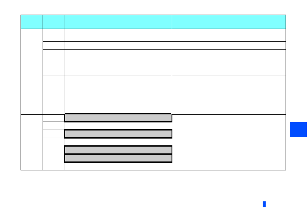
Pr.340
setting
0
(initial
value)
1, 2
Pr.79
setting
0 (initial
value)
1 PU operation mode PU operation mode fixed
2 External operation mode
3, 4 External/PU combined operation mode Operation mode switching is disallowed.
6 External operation mode
7
0 NET operation mode
1 PU operation mode
2
3, 4 External/PU combined operation mode
6
7
Operation mode at power ON or power
restoration
External operation mode
X12 (MRS) signal ON: external operation mode
X12 (MRS) signal OFF: external operation mode
NET operation mode
NET operation mode
X12 (MRS) signal ON........ NET operation mode
X12 (MRS) signal OFF........external operation mode
Operation mode switchover
Switching among the External, PU, and NET operation
mode is enabled.
Switching between the External and Net operation mode is
enabled.
Switching to the PU operation mode is disallowed.
Switching among the External, PU, and NET operation
mode is enabled while running.
Switching among the External, PU, and NET operation
mode is enabled.
External operation mode fixed (Forcibly switched to
External operation mode.)
Same as when Pr.340 = "0"
,
,
4
INVERTER SETTING
23

Pr.340
setting
10, 12
Pr.79
setting
0 NET operation mode
1 PU operation mode Same as when Pr.340 = "0"
2
3, 4 External/PU combined operation mode Same as when Pr.340 = "0"
6
7 External operation mode Same as when Pr.340 = "0"
Operation mode can not be directly changed between the PU operation mode and Network operation mode.
The Pr.340 settings "2 or 12" are mainly used for communication operation using the inverter RS-485 terminal.
When a value other than "9999" (selection of automatic restart after instantaneous power failure) is set in Pr.57 Restart coasting time,
the inverter will resume the same operation state which was in before after power has been restored from an instantaneous power failure.
When Pr.340 = "1 or 10", a start command turns off if power failure has occurred and then restored during a start command is on.
Switching between the PU and NET operation modes is available with the key on the operation panel or the X65 signal.
Refer to page 67 for a switching method from the network.
Operation mode at power ON or power
restoration
Switching between the PU and NET operation mode is
enabled.
NET operation mode NET operation mode fixed
NET operation mode
Switching between the PU and NET operation mode is
enabled while running.
Operation mode switchover
,
,
24
INVERTER SETTING
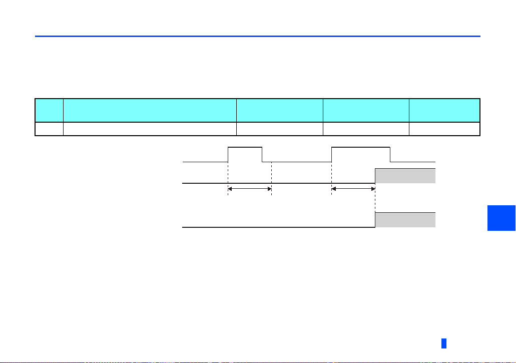
4.3 Operation at communication error occurrence
Normal
Error
Pr.500
setting time
Normal
Error
Communication line status
Alarm signal(LF)
(Pr.502 = 3)
Recognition
ON
Pr.500
setting time
Communication error
(E.OP1)
4.3.1 Operation selection at communication error occurrence (Pr.500 to Pr.502, Pr.779)
You can select operations at communication error occurrences by setting Pr.500 to Pr.502, Pr.779 under network operation.
Waiting time for the communication line error output after a communication error
Waiting time for the communication error output after a communication line error occurrence can be set.
Pr. Name Setting range
500 Communication error execution waiting time 0 to 999.8 s 0.1 s 0 s
When a communication line error occurs and lasts longer than the time set in Pr.500, it is recognized as a communication error.
If the communication returns to normal within the time, it is not recognized as a communication error, and the operation
continues.
Minimum setting
increments
INVERTER SETTING
Initial value
4
25
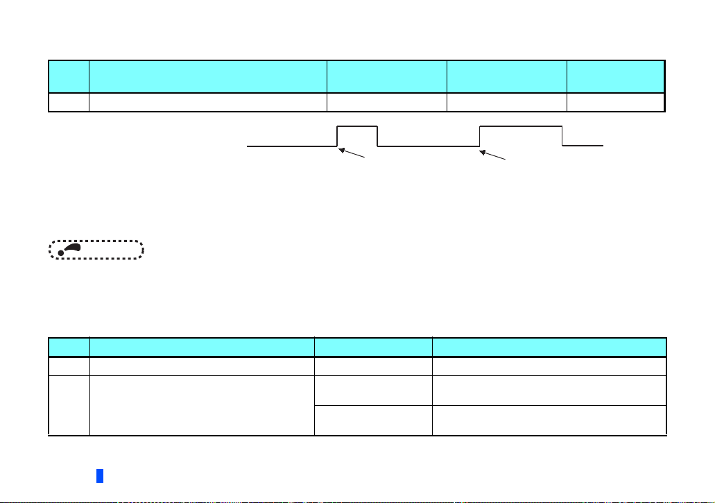
Displaying and clearing the communication error count
The cumulative count of communication error occurrences can be displayed. Write "0" to clear this cumulative count.
Pr. Name Setting range
501 Communication error occurrence count display 0 1 0
Minimum setting
increments
Initial value
Count timing depending on
communication line status
Normal
Error
Incremented by 1
Normal
Error
Incremented by 1
At the point of communication line error occurrence, Pr.501 Communication error occurrence count display is incremented
by 1.
The cumulative count of communication error occurrences is counted from 0 to 65535. When the count exceeds 65535, the
displayed value is cleared and the counting starts over from 0 again.
NOTE
• Communication error count is temporarily stored in the RAM memory. The error count is stored in EEPROM only once
per hour. If power reset or converter reset is performed, Pr.501 setting will be the one that is last stored to EEPROM
depending on the reset timing.
Inverter operation at a communication error occurrence
How the inverter operates at a communication line error or an option unit fault can be set.
Pr. Name Setting range Description
502 Stop mode selection at communication error 0 (Initial Value), 1, 2, 3 Refer to page 27.
When a communication error occurs, the inverter
operates at the set frequency.
The inverter operates at the frequency set before
the communication error occurs.
779
Operation frequency during communication error
Valid when Pr.502 = "3".
26
INVERTER SETTING
0 to 590 Hz
9999 (Initial Value)

About setting
• Operation at an error occurrence
Fault description Pr.502 setting Operation Indication Fault output
0
Communication line
Communication option
itself
When the communication returns to normal within the time period set in Pr.500, the communication option error (E.OP1) does not occur.
1
2
3
0, 3 Coast to stop E. 1 lit Provided
1, 2 Decelerated to stop E. 1 lit after stop Provided after stop
Continued Normal indication Not provided
• Operation after the time in Pr.500 elapses after an error occurrence
Fault description Pr.502 setting Operation Indication Fault output
0 Coast to stop E.OP1 lit Provided
Communication line
Communication option
itself
When an error occurs, the motor is decelerated or coasts to stop, and outputs the fault, independently of the Pr.500 setting.
1
2
3
0, 3
1, 2
Decelerated to stop E.OP1 lit after stop
Continues operation
with the Pr.779 setting.
Kept stopped
E.OP1 kept lit Kept provided
Normal indication
Provided after stop
Not provided
4
INVERTER SETTING
27
 Loading...