

Mitsubishi Electric FR-A8ND Instruction Manual

INVERTER
Plug-in option
FR-A8ND
INSTRUCTION MANUAL
communication function
PRE-OPERATION INSTRUCTIONS
INSTALLATION
WIRING
INVERTER SETTING
FUNCTIONS
OBJECT MAP DEFINITIONS
OBJECT MAP
1
2
3
4
5
6
7
Thank you for choosing this Mitsubishi inverter plug-in option.
Warning
Caution
Caution
This Instruction Manual provides handling information and precautions for use of this product. Incorrect handling might cause an unexpected
fault. Before using this product, always read this Instruction Manual carefully to use this product correctly.
Please forward this Instruction Manual to the end user.
Safety instructions
Do not attempt to install, operate, maintain or inspect the product until you have read through this Instruction Manual and appended
documents carefully and can use the equipment correctly. Do not use this product until you have a full knowledge of the equipment, safety
information and instructions. In this Instruction Manual, the safety instruction levels are classified into "Warning" and "Caution".
The level may even lead to a serious consequence according to conditions. Both instruction levels must be followed
because these are important to personal safety.
Electric Shock Prevention
Incorrect handling may cause hazardous conditions, resulting in death or severe injury.
Incorrect handling may cause hazardous conditions, resulting in medium or slight injury, or may cause only material
damage.
Warning
While the inverter power is ON, do not open the front cover or the wiring cover. Do not run the inverter with the front cover or the wiring cover removed. Otherwise
you may access the exposed high voltage terminals or the charging part of the circuitry and get an electric shock.
Do not remove the inverter front cover even if the power supply is disconnected. The only exception for this would be when performing wiring and periodic
inspection. You may accidentally touch the charged inverter circuits and get an electric shock.
Before wiring or inspection, LED indication of the inverter unit operation panel must be switched OFF. Any person who is involved in wiring or inspection shall wait
for at least 10 minutes after the power supply has been switched OFF and check that there is no residual voltage using a tester or the like. For some time after the
power-OFF, a high voltage remains in the smoothing capacitor, and it is dangerous.
Any person who is involved in wiring or inspection of this equipment shall be fully competent to do the work.
The plug-in option must be installed before wiring. Otherwise you may get an electric shock or be injured.
Do not touch the plug-in optio n or handle the cables with wet hands. Otherwise you may get an electric shock.
Do not subject the cables to scratches, excessive stress, heavy loads or pinching. Otherwise you may get an electric shock.
Injury Prevention
Caution
The voltage applied to each terminal must be the ones specified in the Instruction Manual. Otherwise a burst, damage, etc. may occur.
The cables must be connected to the correct terminals. Otherwise a burst, damage, etc. may occur.
The polarity (+ and -) must be correct. Otherwise a burst or damage may occur.
While power is ON or for some time after power OFF, do not touch the inverter as it will be extremely hot. Touching these devices may cause a burn.
1
Additional Instructions
The following instructions must be also followed. If the product is handled incorrectly, it may cause unexpected fault, an injury, or an electric
shock.
Caution
Transportation and mounting
Do not install or operate the plug-in option if it is damaged or has parts missing.
Do not stand or rest heavy objects on the product.
The mounting orientation must be correct.
Foreign conductive objects must be prevented from entering the inverter. That includes screws and metal fragments or other flammable substance such as oil.
If halogen-based materials (fluorine, chlorine, bromine, iodine, etc.) infiltrate into a Mitsubishi product, the product will be damaged. Halogen-based materials are
often included in fumigant, which is used to sterilize or disinfest wooden packages. When packaging, prevent residual fumigant components from being infiltrated
into Mitsubishi products, or use an alternative sterilization or disinfection method (heat disinfection, etc.) for packaging. Sterilization of disinfection of wooden
package should also be performed be fore packaging the product.
Trial run
Before starting operation, each parameter must be confirmed and adjusted. A failure to do so may cause some machines to make unexpected motions.
Warning
Usage
Do not modify the equipment.
Do not perform parts removal which is not instructed in this manual. Doing so may lead to fault or damage of the product.
Caution
Usage
When parameter clear or all parameter clear is performed, the required parameters must be set again before starting operations. Because all parameters return to
their initial values.
Static electricity in your body must be discharged before you touch the product.
Maintenance, inspection and parts replacement
Do not carry out a megger (insulation resistance) test.
Disposal
The inverter must be treated as industrial waste.
Many of the diagrams and drawings in this Instruction Manual show the inverter without a cover or partially open for explanation. Never operate the inverter in this
manner. The cover must be reinstalled and the instructions in the Instruction Manual must be followed when operating the inverter.
2
General instruction

─ CONTENTS ─
1 PRE-OPERATION INSTRUCTIONS 6
1.1 Unpacking and product confirmation............................................................................................................................6
1.2 Component names ..........................................................................................................................................................7
1.3 MNS LED (operation status indication) .........................................................................................................................8
1.4 Specifications ................................................................................................................................................................10
2 INSTALLATION 11
2.1 Pre-installation instructions .........................................................................................................................................11
2.2 Installation procedure ...................................................................................................................................................12
2.3 Node address setting ....................................................................................................................................................16
3WIRING 18
3.1 Connection to network..................................................................................................................................................18
3.2 Wiring..............................................................................................................................................................................19
4 INVERTER SETTING 22
4.1 Parameter list .................................................................................................................................................................22
4.2 DeviceNet data ...............................................................................................................................................................23
4.2.1 DeviceNet address (Pr. 345)............................................................................................................................................... 24
4.2.2 DeviceNet baud rate (Pr. 346) ............................................................................................................................................ 25
4.3 Operation mode setting ................................................................................................................................................27
4.3.1 Operation mode switching and communication startup mode (Pr.79, Pr.340).................................................................... 27
4.4 Operation at communication error occurrence ..........................................................................................................30
4.4.1 Operation selection at communication error occurrence (Pr.500 to Pr.502, Pr.779) .......................................................... 30
4.4.2 Fault and measures ............................................................................................................................................................ 34
4.5 Inverter reset ..................................................................................................................................................................35
4.6 Frequency and speed settings ..................................................................................................................................... 37
3

5 FUNCTIONS 38
5.1 Output from the inverter to the network......................................................................................................................38
5.2 Input to the inverter from the network.........................................................................................................................39
6 OBJECT MAP DEFINITIONS 40
6.1 Obejct model of DeviceNet ...........................................................................................................................................40
6.2 Data communication type ............................................................................................................................................. 41
6.2.1 Overview of the I/O communication (polling) ...................................................................................................................... 41
6.2.2 Overview of the message communication (Explicit message connection).......................................................................... 42
6.3 Response level...............................................................................................................................................................43
6.3.1 Response level of the I/O communication (polling)............................................................................................................. 43
6.3.2 Response level of the message communication (Explicit message connection)................................................................ 44
6.4 Recommendation for software developers .................................................................................................................44
7 OBJECT MAP 45
7.1 Format of the I/O communication (polling) .................................................................................................................45
7.1.1 Output Instance 20/Input Instance 70................................................................................................................................. 45
7.1.2 Output Instance 21/Input Instance 71................................................................................................................................. 47
7.1.3 Output Instance 126/Input Instance 176 ............................................................................................................................. 49
7.1.4 Output Instance 127/Input Instance 177 ............................................................................................................................. 53
7.2 Message communication (Explicit message connection) .........................................................................................59
7.2.1 Class 0x01 (Identity-Object)................................................................................................................................................ 59
7.2.2 Class 0x03 (DeviceNet Object)...........................................................................................................................................61
7.2.3 Class 0x04 (Assembly Object)............................................................................................................................................ 63
7.2.4 Class 0x05 (DeviceNet connection object) ......................................................................................................................... 64
7.2.5 Class 0x28 (Motor data object)........................................................................................................................................... 71
7.2.6 Class 0x29 (Control supervisor object) ............................................................................................................................... 72
7.2.7 Class 0x2A (AC drive object).............................................................................................................................................. 75
7.2.8 Class 0x66 (Extended object I)........................................................................................................................................... 81
7.2.9 Class 0x67 (Extended object II).......................................................................................................................................... 88
7.2.10 Class 0x70 to 0x79 (Extended object III) ............................................................................................................................ 90
7.2.11 Class 0x80 (Extended object IV)......................................................................................................................................... 91
4

7.2.12 Class 0x90 to 0x94 (Extended object V)............................................................................................................................. 95
7.3 FR-A5ND compatible mode ..........................................................................................................................................96
APPENDIX 99
Appendix 1 EDS file..............................................................................................................................................................99
Appendix 2 DeviceNet Error Code List.............................................................................................................................100
5
1 PRE-OPERATION INSTRUCTIONS
1.1 Unpacking and product confirmation
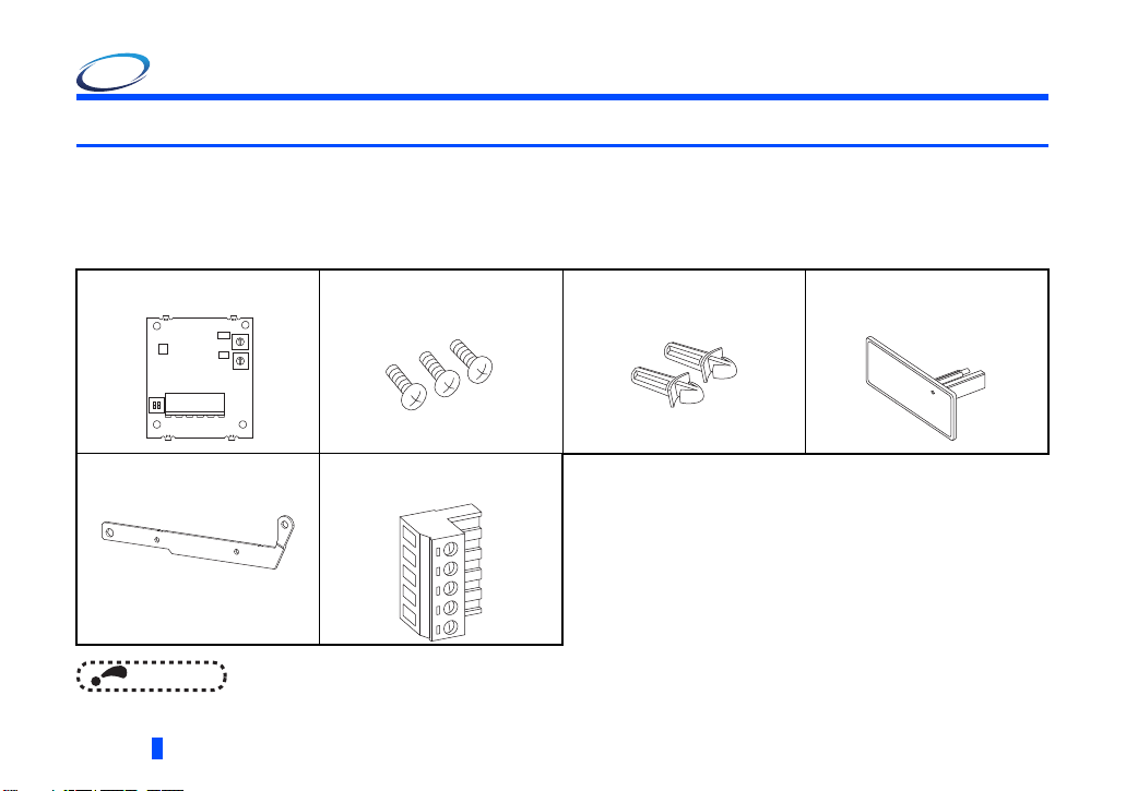
Take the plug-in option out of the package, check the product name, and confirm that the product is as you ordered and intact.
This product is a plug-in option for the FR-A800/F800 series inverter.
Product confirmation
Check the enclosed items.
Plug-in option............................1 Mounting screw (M3 8 mm)...3
0
X10
1
9
MNS
ON
12
Earth plate................................1
(Refer to page 13)
2
8
3
7
4
6
5
0
1
X1
9
2
8
3
7
4
6
5
(Refer to page 13)
Terminal block..........................1
(Refer to page 21)
NOTE
• DeviceNet is a registered trademark of ODVA (Open DeviceNet Vender Association, INC).
6
PRE-OPERATION INSTRUCTIONS
Spacer......................................2
(Refer to page 13 )
Communication option LED
display cover............................1
(Refer to page 12)
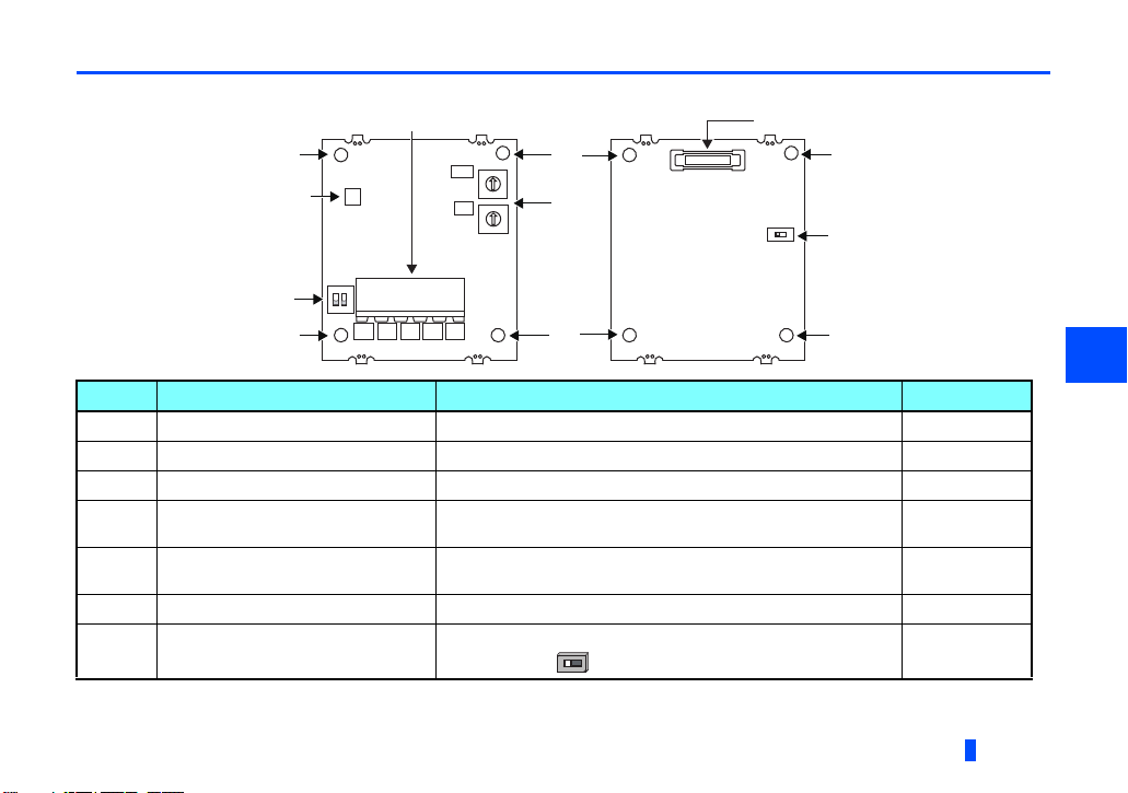
1.2 Component names
O
N
Front view Rear view
(b)
(a)
(e)
(a)
(c)
X10
9
MNS
ON
12
SLD
C-V-
8
7
6
X1
9
8
7
6
V+C+
(a)
0
1
2
3
4
5
(d)
0
1
2
3
4
5
(a)
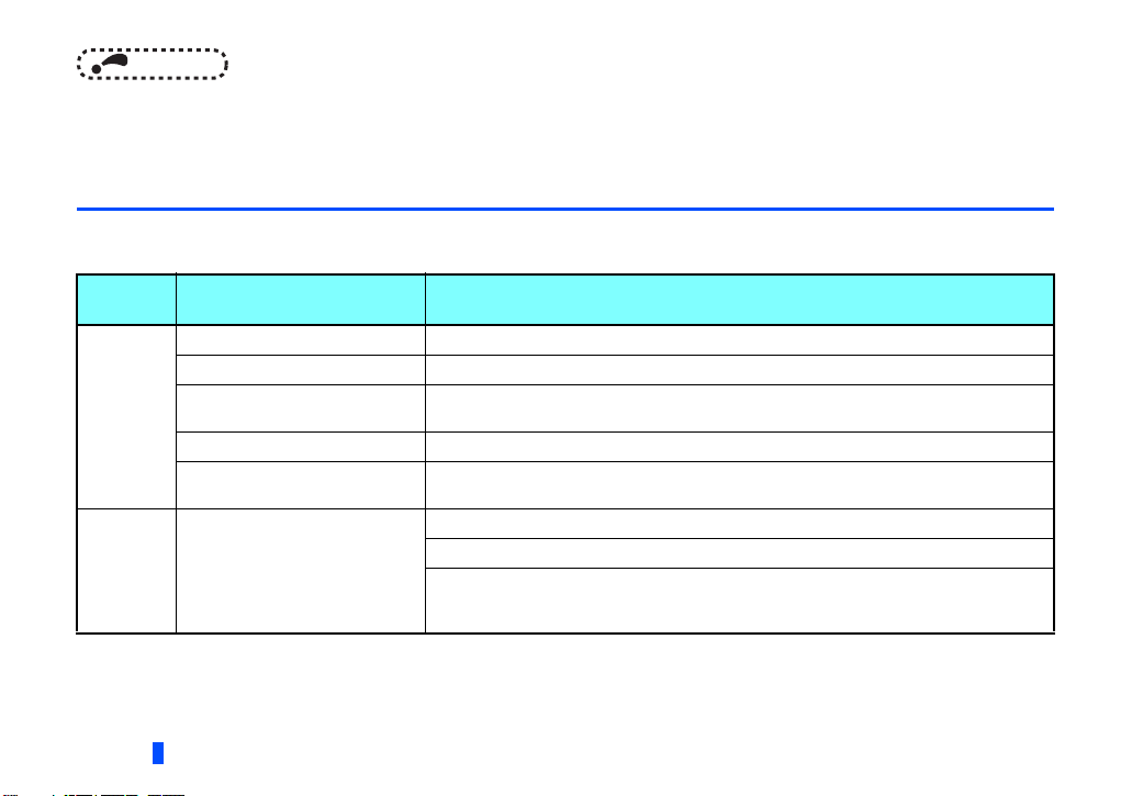
Symbol Name Description Refer to page
a Mounting hole Fixes the option to the inverter with screws, or installs spacers. 13
b Connector for communication Mount the accessory terminal block to connect to the network. 21
c MNS LED (operation status indication) Lit/flicker/off of the LED indicate inverter operation status. 8
d Node address switch
e Compatible mode switch
Set the node address. (In the initial setting, "0" is set for both X10
and X1.)
Switch over to the FR-A5ND compatible mode.
(In the initial status, the switches 1 and 2 are both OFF.)
f Connector Connect to the inverter option connector. 13
g Switch for manufacturer setting
Switch for manufacturer setting. Do not change from the initially-
set status (OFF ).
(f)
(a)
O
N
(g)
(a)
16
96
—
1
PRE-OPERATION INSTRUCTIONS
7
NOTE
• Set the compatible mode switch before switching ON the inverter and do not change the setting while the power is
ON. Otherwise you may get an electric shock.
• Do not turn ON the switch 2 of the compatible mode switch.
1.3 MNS LED (operation status indication)
The MNS LED indicates the operating status of the option unit by its indication status.
Check the position of LED on page 7.
LED
indicator
OFF
Green
(flickering)
8
Description Corrective action
Inverter power OFF Supply power to the inverter.
Network power OFF Supply power to the network.
Cable disconnected
Own node only on the network Supply power to the master.
Different baud rate between the
inverter and master
Connection not established
(Cable connection and network
power are normal.)
Check for a DeviceNet cable disconnection, connector contact fault, and misplaced
terminating resistor.
Set the same baud rate for the inverter (Pr.346) and master.
Check the node address setting (node address switches and Pr.345) of the inverter.
Set the master to the RUN mode.
Check that the size (number of bytes) of the I/O communication from the master matches
with that set in Pr.346 of the inverter. (For how to check the I/O communication size of the
master, refer to the Instruction Manual of the master device.)
PRE-OPERATION INSTRUCTIONS

LED
indicator
Green (ON)
Red
(flickering)
Red (ON)
Description Corrective action
Connection established
(The inverter power is ON and the
master on the network has
recognized this option unit.
The green LED stays ON during
communication.)
I/O communication connection
timeout
Network power OFF
Overlapping node address Check that the node address is not overlapping with those of other devices.
Incorrect baud rate setting Set the same baud rate for the inverter (Pr.346) and master.
Communication error due to cable
disconnection or intermittent
network power OFF
If the communication is set as the operation or speed command source for the inverter operation, a communication error occurs. For the
inverter operation at communication error, refer to page 31.
Time limit = 4 EPR.
(EPR = Expected Pack Rate Class 0x05 Instance 2 Attribute 9 (Refer to page 66))
<When the inverter is not running even with the green LED ON>
• Check that the correct data is sent from the master to the I/O communication format
specified in Pr.346. (For how to check the data to be sent from the master, refer to the
Instruction Manual of the master device.)
• Check that the inverter is in the NET operation mode, Pr.338 Communication operation
command source = "0", or Pr.550 NET mode operation command source selection =
"0 or 9999".
Check the EPR (Expected Packet Rate) setting of the I/O communication of the master
again.
(For how to set the EPR, refer to the Instruction Manual of the master device.)
Check for a DeviceNet cable disconnection, connector contact fault, and misplaced
terminating resistor.
Review the power supply method for the network so that the power does not turn OFF
again.
After connecting a master to an inverter (FR-A8ND) with terminating resistors, check for a
cable disconnection, connector contact fault, and network power supply drop.
1
PRE-OPERATION INSTRUCTIONS
9

1.4 Specifications
Item Specifications
Control power
Power
supply
Connector type Open-type connector
DeviceNet communication
specifications
Communication cable Use a DeviceNet standard thick or thin cable
Maximum cable length
Communication speed 125 kbps, 250 kbps, 500 kbps
Number of inverters
connected
Response time Refer to page 4 3.
supply
Network power
Supplied from the inverter
Input voltage: 11 to 28 V
Consumption current: 90 mA maximum
Conforms to ODVA DeviceNet Specification. Group2 server. Support UCMM
500 m (125 kbps)
250 m (250 kbps)
100 m (500 kbps)
64 (including master)
The number of inverters connectable is 64 - 1 = 63 when a minimum of one node as a master is connected.
10
PRE-OPERATION INSTRUCTIONS
2 INSTALLATION
2.1 Pre-installation instructions
Check that the inverter's input power and the control circuit power are both OFF.
Caution
With input power ON, do not install or remove the plug-in option. Otherwise, the inverter and plug-in option may be damaged.
To avoid damage due to static electricity, static electricity in your body must be discharged before you touch the product.
2
INSTALLATION
11
2.2 Installation procedure
Cut off with a nipper, etc.
Cut off with a nipper, etc.
Communication option LED cover
Installing the communication option LED display cover
(1) Remove the inverter front cover. (Refer to Chapter 2 of the Instruction Manual (Detailed) of the inverter for details on how
to remove the front cover.)
Mount the cover for displaying the operation status indication LED for the communication option on the inverter front cover.
(2) Cut off hooks on the rear of the inverter front cover with nipper, etc. and
open the window for fitting the LED display cover.
(3) Fit the communication option LED display cover to the front side of the
front cover. Align the LED display cover with the LED position on the
circuit board of the option. Push the LED display cover until it is fixed with
the hooks.
NOTE
The protective structure (JEM1030) changes to the open type (IP00).
Caution
Take care not to hurt your hand and such with portions left by cutting hooks of the rear of the front cover.
12
INSTALLATION
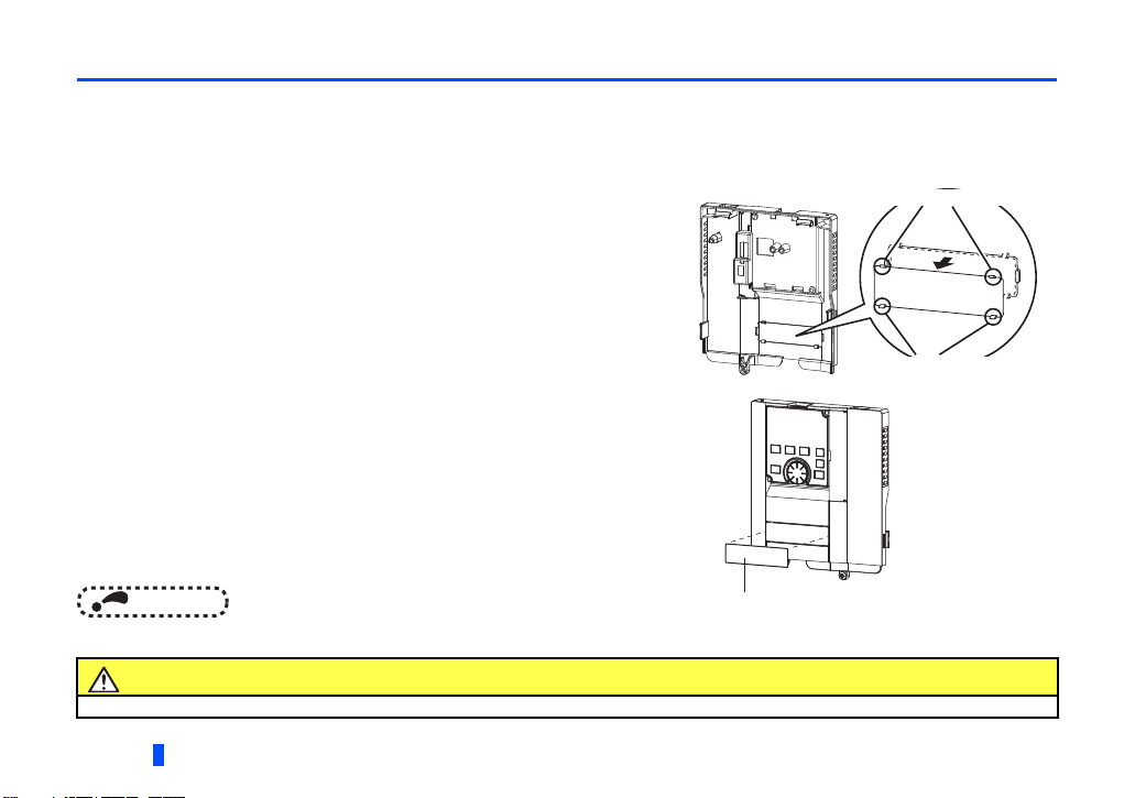
Installing the option
(1) For the two mounting holes (as shown in the next page)
that will not be tightened with mounting screws, insert
spacers.
(2) Fit the connector of the plug-in option to the guide of the
connector on the inverter unit side, and insert the plug-in
option as far as it goes. (Insert it to the inverter option
connector 1.)
(3) Fit the one location on the left of the earth plate (as shown
in the next page) securely to the inverter unit by screwing
in the supplied mounting screw. (tightening torque 0.33
N·m to 0.40 N·m)
(4) Fit the one location on the left of the plug-in option
securely to the inverter unit and the right of the plug-in
option to the inverter unit together with the earth plate by
screwing in the supplied mounting screws. (tightening
torque 0.33 N·m to 0.40 N·m) If the screw holes do not
line up, the connector may not be inserted deep enough.
Check the connector.
Inverter side
option connector
Spacer
Spacer
2
Earth plate
Example of installation to connector 1
INSTALLATION
13
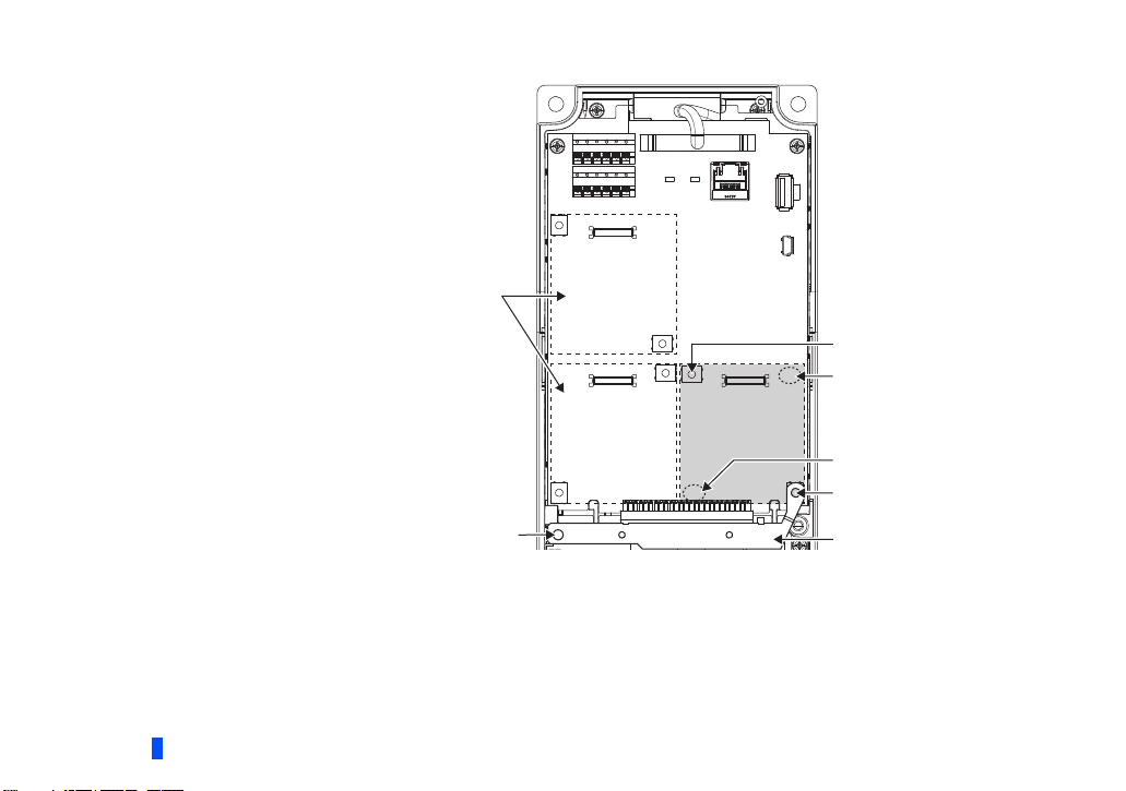
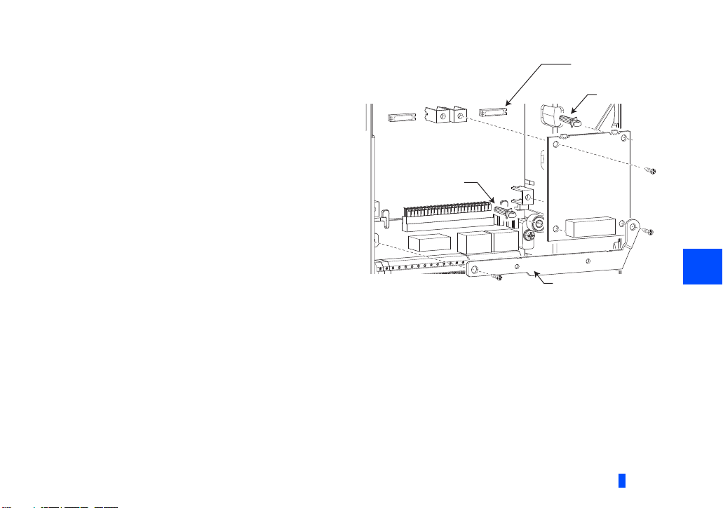
Spacer
Spacer
Mounting screw
Do not insert the plug-in option to the connector 2 or 3.
Mounting screw
Connector 1Connector 2
Connector 3
Insertion positions for screws and spacers
Earth plate
Mounting screw
14
INSTALLATION
NOTE
• When mounting/removing the plug-in option, hold the sides of the option. Do not press on the parts on the option
circuit board. Stress applied to the parts by pressing, etc. may cause a failure.
• Caution must be applied to mounting screws falling off when removing and mounting the plug-in option.
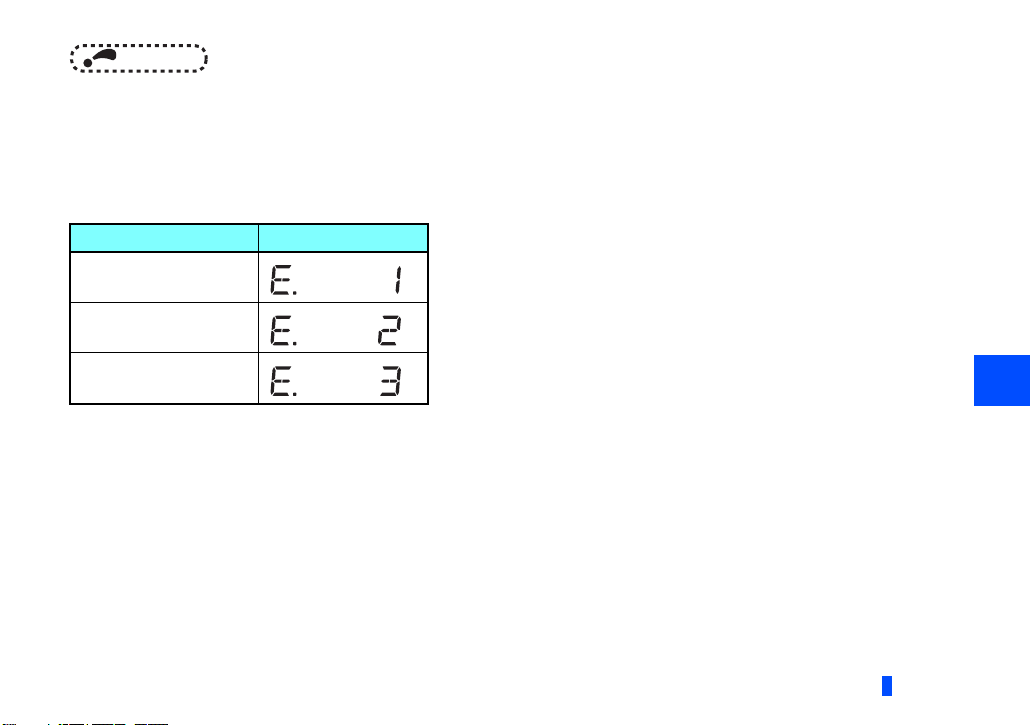
• When using this plug-in option, insert it to the inverter option connector 1. If it is inserted to the option connector 2 or 3,
the protective function (E.2 or E.3) is activated and the inverter will not operate.
• Even if the option is inserted to the option connector 1, when the inverter cannot recognize that the option is mounted
due to improper installation, etc., the protective function (E.1) is activated.
Mounted position Fault indication
Option connector 1
Option connector 2
Option connector 3
• When removing the plug-in option, remove the two screws on the left and right, then pull it straight out. Pressure
• Always attach the earth plate because a malfunction due to noises may occur without it.
applied to the connector and to the option board may break the option.
INSTALLATION
2
15
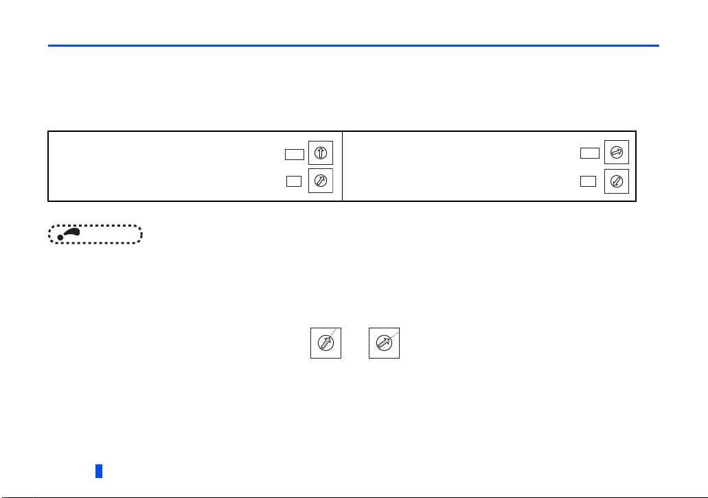
2.3 Node address setting
Setting with node address switch
Set the node address between "0 and 63" using the node address switches on the FR-A8ND board. (Refer to page 7.)
The setting is applied at the next power-ON or inverter reset.
Set the arrow () of the corresponding switches to the number to set a desired address.
• Setting example
Node address 1:
Set the "" of X10 to "0" and the "" of X1 to "1".
NOTE
• Set the inverter node address before switching ON the inverter and do not change the setting while the power is ON.
Otherwise you may get an electric shock.
• Set the node address switch to the switch number position correctly. If the switch is set between numbers, normal data
communication can not be made.
• When the node address switches are set to "64 or higher", the node address set by Pr.345 or in "Class 0x03, Instance
1, Attribute 1" becomes valid.
• You cannot set the same node address to other devices on the network.
(If different devices have the same node address, the communication cannot be established properly.)
16
INSTALLATION
X10
X1
0
1
9
2
8
3
7
4
6
5
0
1
9
2
8
3
7
4
6
5
Good
example
0
1
9
8
7
4
6
5
Node address 26:
Set the "" of X10 to "2" and the "6" of X1 to "6".
Bad
example
0
1
9
2
3
2
8
3
7
4
6
5
X10
X1
0
1
9
2
8
3
7
4
6
5
0
1
9
2
8
3
7
4
6
5

Set with parameter (Pr.345)
After setting the node address switches to "64 or higher", set the inverter parameter (Pr.345 DeviceNet address). When the
node address switches are set to "0 to 63", the node address switch setting is valid. The setting is applied at the next powerON or inverter reset. (Refer to page 24)
Setting with master
After setting the node address switches to "64 or higher", set "Class 0x03, Instance 1, Attribute 1" using the master. The setting
value is applied to Pr.345. When the node address switches are set to "0 to 63", the node address switch setting is valid. (Refer
to page 61)
All connections are released and a set value is immediately applied.
2
INSTALLATION
17
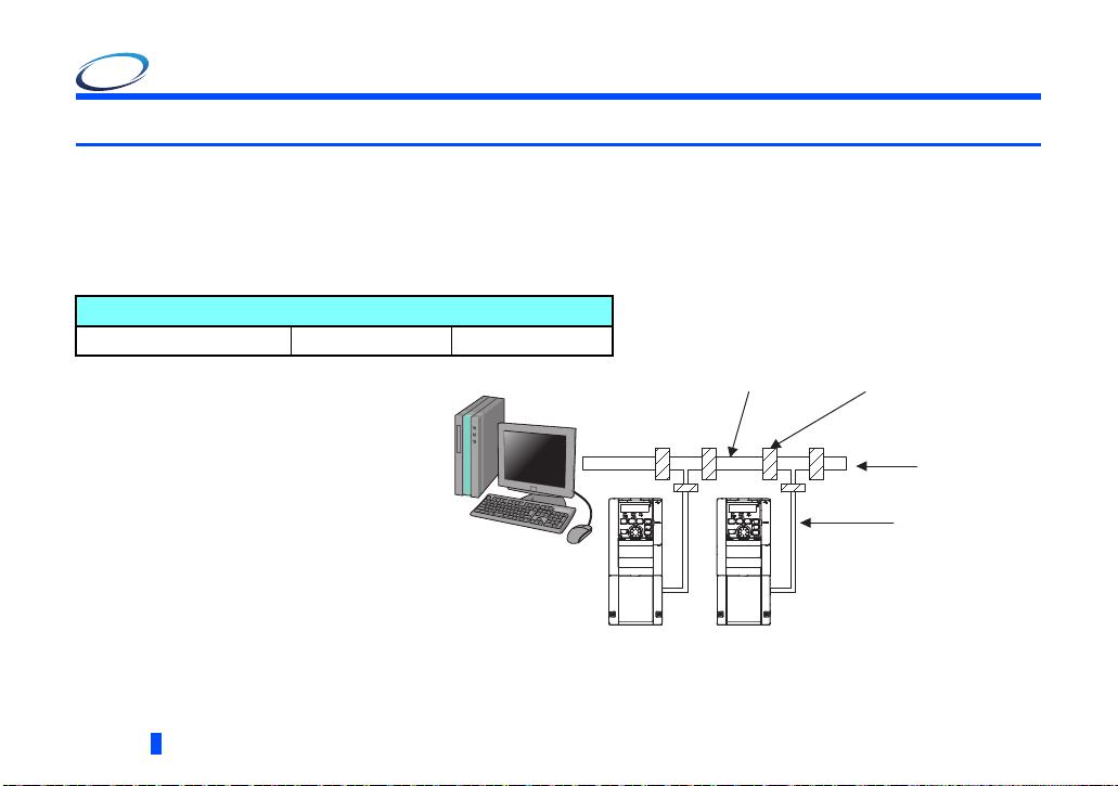
3 WIRING
Inverter
Trunk cable
Trunk connector
Drop cable
Terminating
resistor
Inverter
3.1 Connection to network
(1) Be sure to check the following before connecting the inverter to the network.
• Check that the FR-A8ND is securely inserted into the inverter. (Refer to page 10.)
• Check that the correct node address is set. (Refer to page 16.)
• Check that a drop cable is firmly connected to the FR-A8ND. (Refer to page 19.)
(2) Make sure that the terminating resistor is installed at each end (between C+ and C-) of the trunk cable. These resistors
must meet the following requirements.
Requirements of terminating resistors
R (resistance value) = 121 1% metal film 0.25 W
(3) Connect drop cables to the trank cable.
• If the trunk connector is a DeviceNet
sanctioned pluggable or sealed
connector, the connection to the active
network can be made at any time
whether the inverter is ON or OFF. The
option unit automatically detects when
the connection is completed.
• If connecting to the network with free
wires, power to the network and inverter
should be shut off as a safety
precaution in case two or more signal
wires are accidentally shorted together.
18
WIRING
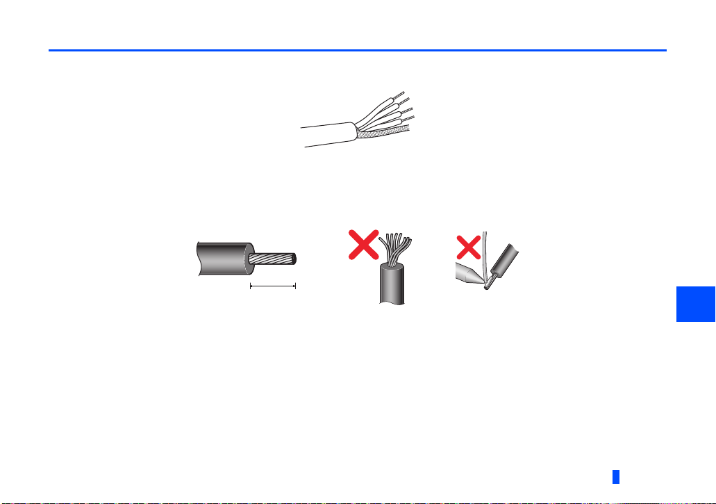
3.2 Wiring
7 mm
(1) Strip the sheath back about 40 mm on the free wire end of the drop cable to expose the four colored signal wires and the
silver shield wire.
(2) Strip the sheath back of each signal cable to use. If the length of the sheath pealed is too long, a short circuit may occur
among neighboring wires. If the length is too short, wires might come off.
Wire the stripped cable after twisting it to prevent it from becoming loose. In addition, do not solder it.
Cable stripping length
Use a blade type terminal as required.
WIRING
3
19
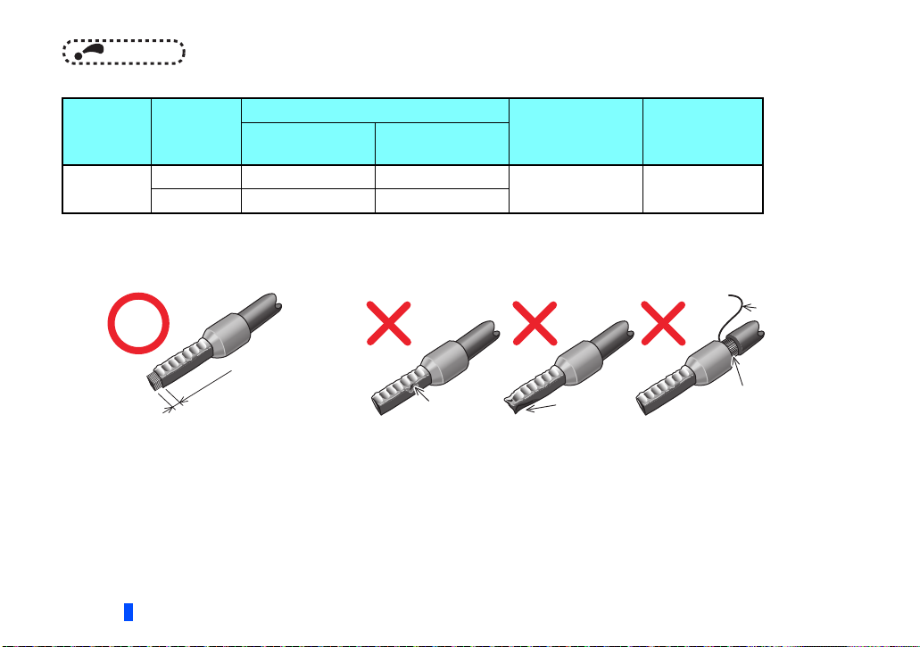
NOTE
Wire
Sleeve
0 to 0.5mm
• Blade terminals available on the market (as of February 2012)
Ter mina l
screw size
M3
20
Wire size
(mm2)
0.3 to 0.5 AI 0,5-6WH A 0,5-6
0.5 to 0.75 AI 0,75-6GY A 0,75-6
Ferrule terminal model
With insulation
sleeve
Without insulation
sleeve
Manufacturer
Phoenix Contact
Co.,Ltd.
Crimping tool
name
CRIMPFOX 6
Insert wires to a blade terminal, and check that the wires come out for about 0 to 0.5 mm from a sleeve.
Check the condition of the blade terminal after crimping. Do not use a blade terminal of which the crimping is
inappropriate, or the face is damaged.
Unstranded
wires
Wires are not inserted
into the sleeve
0 to 0.5mm
Sleeve
Wire
Damaged
Crumpled tip
WIRING
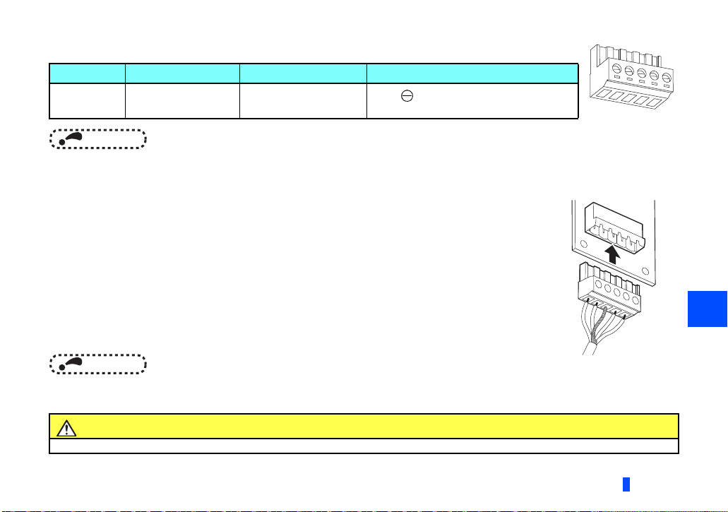
(3) Loosen the terminal screw and insert the cable into the terminal according to the terminal assignment.
V-
C-
C+
V+
Terminal layout
(Black)
(Blue)
(White)
(Red)
Tighten each cable with fixing screws to the recommended tightening torque.
Screw size Tightening torque Cable size Screwdriver
M3 0.5 N·m to 0.6 N·m
0.3 mm
2
to 0.75 mm
Small flat-blade screwdriver
2
(Tip thickness: 0.4 mm/ tip width: 2.5 mm)
NOTE
• Undertightening can cause cable disconnection or malfunction. Overtightening can cause a
short circuit or malfunction due to damage to the screw or unit.
(4) Connect the terminal block to the connector for communication of the communication option
mounted on the inverter.
NOTE
• When wiring cables to the inverter's RS-485 terminals with a plug-in option mounted, take caution not to let the cables
touch the circuit board of the option or of the inverter. Otherwise, electromagnetic noises may cause malfunctions.
Caution
After wiring, wire offcuts must not be left in the inverter. They may cause an error, failure or malfunction.
WIRING
3
21
4 INVERTER SETTING
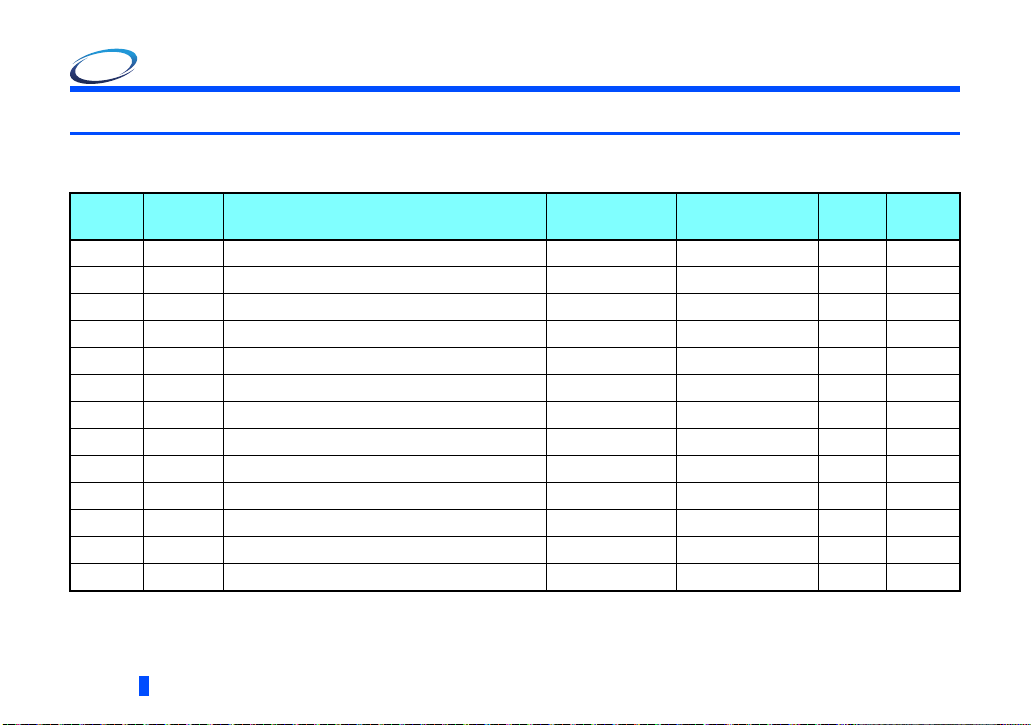
4.1 Parameter list
The following parameters are used for the communication option (FR-A8ND).
Set the values according to need.
Pr.
79 D000 Operation mode selection 0 to 4, 6, 7 1 0 27
338 D010 Communication operation command source 0, 1 1 0
339 D011 Communication speed command source 0, 1, 2 1 0
340 D001 Communication startup mode selection 0, 1, 2, 10, 12 1 0 27
342 N001 Communication EEPROM write selection 0, 1 1 0
345, N200, DeviceNet address 0 to 4095 1 63 24
, N201 , DeviceNet baud rate 0 to 4095 1 132 25
346
N010 Communication reset selection 0, 1 1 0 30
349
N011 Communication error execution waiting time 0 to 999.8 s 0.1 s 0 s 30
500
N012 Communication error occurrence count display 0 1 0 31
501
502 N013 Stop mode selection at communication error 0, 1, 2, 3 1 0 31
D012 NET mode operation command source selection 0, 1, 9999 1 9999
550
779 N014 Operation frequency during communication error 0 to 590 Hz, 9999 0.01 Hz 9999 31
22
Pr.
group
Parameters which can be displayed when the plug-in option (FR-A8ND) is mounted.
The setting is reflected after inverter reset or at the next power-ON.
Refer to the Instruction Manual (Detailed) of the inverter for the parameter details.
Name
INVERTER SETTING
Setting
range
Minimum setting
increments
Initial
value
Refer to
page

4.2 DeviceNet data
DeviceNet communication startup data can be set with the inverter parameter without using a DeviceNet configuration tool.
For the setting method with an EDS file (Refer to page 99) DeviceNet configuration tool, refer to the configuration tool manual.
4
INVERTER SETTING
23
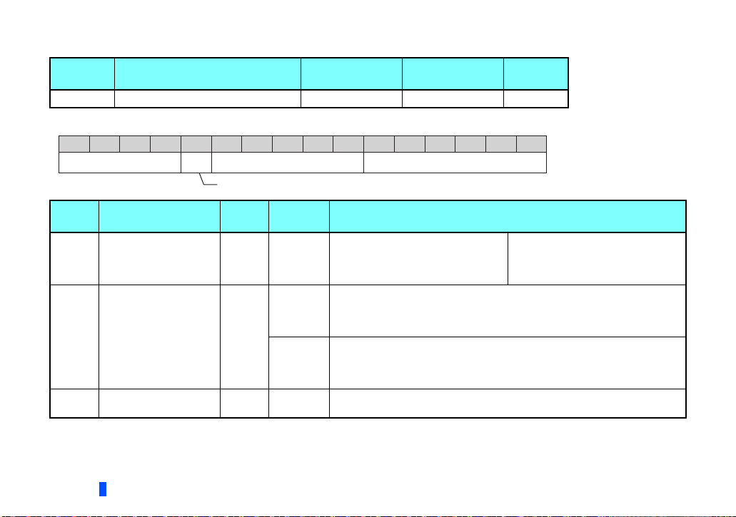
4.2.1 DeviceNet address (Pr. 345)
Pr. Name Setting range
345 DeviceNet address 0 to 4095 1 63
Minimum setting
increments
The definition of Pr. 345 is as follows.
Reserved
ResCom
Device Node AddressReserved
Communication continuation selection (ResCom)
Bit Item
0 to 5 Device Node Address 63 0 to 63
11
12 to 15 Reserved 0 0
Selection of continuous
communication at
inverter reset (ResCom)
To enable the device node address of bit 0 to 5, set the node address switches to "64 or higher". (Refer to page 16)
For an error reset via DeviceNet communication, the communication continues.
When operating the inverter through the DeviceNet communication, set Pr.3400 in advance to enable the inverter to run in the NET
operation mode after the inverter reset.
Initial
value
0
Setting
range
0
1
Definition
Node Address (MAC ID) of device is
set between 0 and 63.
Reset the option unit in synchronization with the inverter.
When connection is timed out, communication may not resume according to
the master action. In this case, release connection and reestablish to make
communication enabled.
The option unit will not be reset even if the inverter is reset and communication
continues.
After inverter reset, preset a value other than "0" in Pr. 340 so that the inverter
starts in Network operation mode.
Set "0" always. When a value other than "0" is set, the inverter operates as
when "63" (initial value) is set in Pr. 345.
Initial
value
0123456789101112131415
Node address can be set with
DeviceNet Object Class 0x03,
Instance1, Attribute1.
(Refer to page 61)
24
INVERTER SETTING
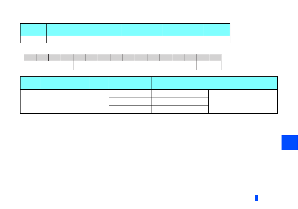
4.2.2 DeviceNet baud rate (Pr. 346)
Pr. Name Setting range
346 DeviceNet baud rate 0 to 4095 1 132
Minimum setting
increments
Set baud rate etc. to start DeviceNet communication.
Reserved Input Assembly Output Assembly Baud Rate
Bit Item
0, 1 Baud Rate 0
Initial
value
Setting range Definition
0, 3 125 kbps
1 250 kbps
2 500 kbps
Initial
value
0123456789101112131415
This value can be set with
DeviceNet Object Class 0x03
Instance 1 Attribute 2.
(Refer to page 61)
4
INVERTER SETTING
25
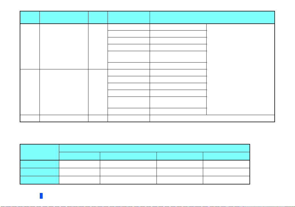
Bit Item
2 to 6 Output Assembly 1
7 to 11 Input Assembly 1
12 to 15 Reserved 0 0 Set "0" always.
Initial
value
Setting range Definition
0 Output Instance 20 (0x14) • Set the same value for input
1 Output Instance 21 (0x15)
6 Output Instance 126 (0x7E)
7 Output Instance 127 (0x7F)
8, 14
Other than the above Output Instance 21 (0x15)
0 Input Instance 70 (0x46)
1 Input Instance 71 (0x47)
6 Input Instance 176 (0xB0)
7 Input Instance 177 (0xB1)
8, 14
Other than the above Input Instance 71 (0x47)
For manufacturer setting. Do
not set.
For manufacturer setting. Do
not set.
assembly and output assembly.
• The value can be set with Control
Supervisor Class 0x29 Instance 1
Attribute 140, 141.
(Refer to page 72 )
Set Pr.346 according to the baud rate and Output/Input Instances (number of bytes of communicated data) of the I/O
communication as shown in the following table.
Baud rate
125 kbps
250 kbps
500 kbps
26
Output/Input Instances (No. of bytes of communicated data) of the I/O communication
20/70 (4) 21/71 (4) 126/176 (6) 127/177 (8)
0, 3 132 (initial value), 135 792, 795 924, 927
1 133 793 925
2 134 794 926
INVERTER SETTING

4.3 Operation mode setting
4.3.1 Operation mode switching and communication startup mode (Pr.79, Pr.340)
Operation mode switching conditions
Operation mode switching conditions
• The inverter is at a stop;
• Both the STF and STR signals are off; and
• The Pr.79 Operation mode selection setting is correct.
(Set with the operation panel of the inverter.)
Operation mode selection at power ON and at restoration from instantaneous power failure
The operation mode at power ON and at restoration from instantaneous power failure can be selected.
Set a value other than "0" in Pr.340 Communication startup mode selection to select the network operation mode.
After started in network operation mode, parameter write from the network is enabled.
NOTE
• Change of the Pr.340 setting is valid when powering on or resetting the inverter.
• Pr.340 can be changed with the operation panel independently of the operation mode.
• When setting a value other than 0 in Pr.340, make sure that the initial settings of the inverter are correct.
• When the inverter has received a communication establishment request from the master in the External operation
mode or switchover mode, the operation mode is switched to the NET operation mode.
However, after the error reset, the inverter enters the External operation mode and no communication establishment
request may be sent from the master. Thus, setting Pr.340 "0" in advance is recommended.
• Refer to the Instruction Manual (Detailed) of the inverter for details of Pr.79, Pr.340.
4
INVERTER SETTING
27

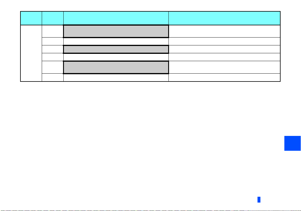
Pr.340
setting
0
(initial
value)
1, 2
Pr.79
setting
0 (initial
value)
1 PU operation mode PU operation mode fixed
2 External operation mode
3, 4 External/PU combined operation mode Operation mode switching is disallowed
6 External operation mode
7
0 NET operation mode
1 PU operation mode
2
3, 4 External/PU combined operation mode
6
7
Operation mode at power ON or power
restoration
External operation mode
X12 (MRS) signal ON: external operation mode
X12 (MRS) signal OFF: external operation mode
NET operation mode
NET operation mode
X12 (MRS) signal ON........ NET operation mode
X12 (MRS) signal OFF........external operation mode
Operation mode switchover
Switching among the External, PU, and NET operation
mode is enabled
Switching between the External and Net operation mode is
enabled
Switching to the PU operation mode is disallowed
Switching among the External, PU, and NET operation
mode is enabled while running.
Switching among the External, PU, and NET operation
mode is enabled
External operation mode fixed (Forcibly switched to
External operation mode.)
Same as when Pr.340 = "0"
,
,
28
INVERTER SETTING
Pr.340
setting
10, 12
Pr.79
setting
0 NET operation mode
1 PU operation mode Same as when Pr.340 = "0"
2
3, 4 External/PU combined operation mode Same as when Pr.340 = "0"
6
7 External operation mode Same as when Pr.340 = "0"
Operation mode can not be directly changed between the PU operation mode and Network operation mode.
The Pr.340 settings "2, 12" are mainly used for communication operation using the inverter RS-485 terminal.
When a value other than "9999" (selection of automatic restart after instantaneous power failure) is set in Pr.57 Restart coasting time,
the inverter will resume the same operation state which was in before after power has been restored from an instantaneous power failure.
When Pr.340 = "1, 10", a start command turns off if power failure has occurred and then restored during a start command is on.
Switching between the PU and NET operation modes is available with the key on the operation panel or the X65 signal.
Refer to pa ge 77 for a switching method from the network.
Operation mode at power ON or power
restoration
Switching between the PU and NET operation mode is
enabled
NET operation mode NET operation mode fixed
NET operation mode
Switching between the PU and NET operation mode is
enabled while running
Operation mode switchover
,
,
4
INVERTER SETTING
29
 Loading...