

Mitsubishi Electric FR-A8NCE Instruction Manual

INVERTER
Plug-in option
PRE-OPERATION INSTRUCTIONS
1
FR-A8NCE
INSTRUCTION MANUAL
Network
communication function
INSTALLATION
WIRING
INVERTER SETTING
FUNCTION OVERVIEW
I/O SIGNAL LIST
DETAILS OF I/O SIGNALS
PROGRAMMING EXAMPLES
2
3
4
5
6
7
8
Thank you for choosing this Mitsubishi Electric inverter plug-in option.
WARNING
CAUTION
CAUTION
This Instruction Manual provides handling information and precautions for use of this product. Incorrect handling might cause an unexpected
fault. Before using this product, read all relevant instruction manuals carefully to ensure proper use.
Please forward this Instruction Manual to the end user.
Safety instructions
Do not attempt to install, operate, maintain or inspect this product until you have read this Instruction Manual and appended documents
carefully. Do not use this product until you have a full knowledge of this product mechanism, safety information and instructions. In this
Instruction Manual, the safety instruction levels are classified into "WARNING" and "CAUTION".
Incorrect handling may cause hazardous conditions, resulting in death or severe injury.
Incorrect handling may cause hazardous conditions, resulting in medium or slight injury, or may cause only
material damage.
Note that even the level may lead to a serious consequence depending on conditions. Be sure to follow the
instructions of both levels as they are critical to personnel safety.
Electric shock prevention
WARNING
Do not remove the front cover or the wiring cover of the inverter while the inverter power is ON. Do not operate the inverter with any cover or wiring cover removed,
as accidental contact with exposed high-voltage terminals and internal components may occur, resulting in an electrical shock.
Even if power is OFF, do not remove the front cover of the inverter except for wiring or periodic inspection as you may accidentally touch the charged circuits and
get an electric shock.
Before wiring or inspection, check that the display of the inverter operation panel is OFF. Any person who is involved in wiring or inspection shall wait for 10 minutes
or longer after power OFF and check that there are no residual voltage using a tester or the like. The capacitor is charged with high voltage for some time after
power OFF, and it is dangerous.
Any person who is involved in wiring or inspection of this product shall be fully competent to do the work.
This product must be installed before wiring. Otherwise you may get an electric shock or be injured.
Do not subject the cables to scratches, excessive stress, heavy loads or pinching. Doing so may cause an electric shock.
Do not touch this product or handle the cables with wet hands. Doing so may cause an electric shock.
Injury prevention
CAUTION
The voltage applied to each terminal must be as specified in the Instruction Manual. Otherwise a burst, damage, etc. may occur.
The cables must be connected to the correct terminals. Otherwise a burst, damage, etc. may occur.
The polarity (+ and -) must be correct. Otherwise a burst, damage, etc. may occur.
While power is ON or for some time after power OFF, do not touch the inverter as it will be extremely hot. Doing so may cause a burn.
1
Additional instructions
The following instructions must be also followed. If this product is handled incorrectly, it may cause unexpected fault, an injury, or an electric
shock.
CAUTION
Transportation and installation
Do not stand or place heavy objects on this product.
The installing orientation of this product must be correct.
Do not install or operate this product if it is damaged or has parts missing.
Foreign conductive objects must be prevented from entering the inverter. That includes screws and metal fragments or other flammable substance such as oil.
If halogen-based materials (fluorine, chlorine, bromine, iodine, etc.), included in fumigants to sterilize or disinfect wooden packages, infiltrate into this product, the
product may be damaged. Prevent residual fumigant compon ents from being infiltrated into the product when packaging, or use an alternative sterilization or
disinfection method (heat disinfection, etc.). Note that sterilization or disinfection of wooden package should also be performed before packing the product.
Test operation
Before starting operation, confirm or adjust the parameter settings. Failure to do so may cause some machines to make unexpected motions.
WARNING
Usage
Do not modify this product.
Do not remove any part which is not instructed to be removed in the Instruction Manuals. Doing so may lead to a failure or damage of this product.
CAUTION
Usage
As all parameters return to their initial values after Parameter clear or All parameter clear is performed, the needed parameters for operation of the inverter and this
product must be set again bef ore the operation is started.
To avoid damage to this product due to static electricity, static electricity in your body must be discharged before you touch this product.
Maintenance, inspection and parts replacement
Do not carry out a megger (insulation resistance) test.
Disposal
This product must be treated as industrial waste.
For clarity purpose, illustrations in this Instruction Manual may be drawn with covers or safety guards removed. Ensure all covers and safety guards are properly
installed prior to starting operation.
2
General instruction

─ CONTENTS ─
1 PRE-OPERATION INSTRUCTIONS 6
1.1 Unpacking and product confirmation............................................................................................................................6
1.2 Parts..................................................................................................................................................................................7
1.3 CC-Link IE Field Network communication specifications ...........................................................................................9
2INSTALLATION 10
2.1 Pre-installation instructions .........................................................................................................................................10
2.2 Installation procedure ...................................................................................................................................................11
3WIRING 15
3.1 System configuration example.....................................................................................................................................15
3.2 Network configuration...................................................................................................................................................16
3.3 Network components ....................................................................................................................................................17
3.3.1 Connection cable ................................................................................................................................................................ 17
3.3.2 Hubs.................................................................................................................................................................................... 17
3.4 Wiring..............................................................................................................................................................................18
3.4.1 Ethernet cable connection .................................................................................................................................................. 18
3.4.2 Precautions .........................................................................................................................................................................20
4 INVERTER SETTING 23
4.1 Parameter list ................................................................................................................................................................. 23
4.2 Operation mode setting ................................................................................................................................................25
4.2.1 Operation mode switching and communication startup mode (Pr.79, Pr.340).................................................................... 25
4.3 Operation at communication error occurrence ..........................................................................................................28
4.3.1 Operation selection at communication error occurrence (Pr.500 to Pr.502, Pr.779) .......................................................... 28
4.3.2 Fault and measures ............................................................................................................................................................ 33
4.4 Inverter reset .................................................................................................................................................................. 34
3

4.5 CC-Link IE Field Network function setting ..................................................................................................................36
4.5.1 Network number setting (Pr. 434) ....................................................................................................................................... 36
4.5.2 Station number setting (Pr. 435)......................................................................................................................................... 36
4.5.3 Frequency command with sign (Pr. 541) ............................................................................................................................ 37
5 FUNCTION OVERVIEW 39
5.1 Output from the inverter through the network............................................................................................................39
5.2 Input to the inverter through the network ...................................................................................................................40
5.3 Cyclic transmission.......................................................................................................................................................41
5.3.1 Data flow and link device assignment................................................................................................................................. 41
6 I/O SIGNAL LIST 44
6.1 Remote I/O (64 points fixed) .........................................................................................................................................44
6.2 Remote register (128 words fixed) ...............................................................................................................................47
7 DETAILS OF I/O SIGNALS 53
7.1 Details of remote input and output signals.................................................................................................................53
7.1.1 Output signals (master module to inverter (FR-A8NCE)).................................................................................................... 53
7.1.2 Input signals (inverter (FR-A8NCE) to master module) ...................................................................................................... 56
7.2 Details of remote register .............................................................................................................................................58
7.2.1 Remote register (master module to inverter (FR-A8NCE))................................................................................................. 58
7.2.2 Remote register (inverter (FR-A8NCE) to master module)................................................................................................. 60
7.2.3 Instruction codes................................................................................................................................................................. 63
7.2.4 Monitor codes ..................................................................................................................................................................... 67
7.3 Torque command / torque limit through CC-Link IE Field Network
communication (only for the FR-A800 series) ............................................................................................................68
8 PROGRAMMING EXAMPLES 70
8.1 Programming example for reading the inverter status ..............................................................................................75
8.2 Programming example for setting the operation mode .............................................................................................76
4

8.3 Programming example for setting the operation commands....................................................................................77
8.4 Programming example for monitoring the output frequency....................................................................................78
8.5 Programming example for parameter reading............................................................................................................79
8.6 Programming example for parameter writing .............................................................................................................80
8.7 Programming example for setting the running frequency ........................................................................................81
8.8 Programming example for fault record reading .........................................................................................................83
8.9 Programming example for resetting the inverter at inverter error............................................................................84
8.10 Instructions ....................................................................................................................................................................85
APPENDIX 87
5
1 PRE-OPERATION INSTRUCTIONS
1.1 Unpacking and product confirmation
Take the product out of the package, check the product name, and confirm that the product is as you ordered and intact.
This product is a plug-in option made for the FR-A800/F800 series.
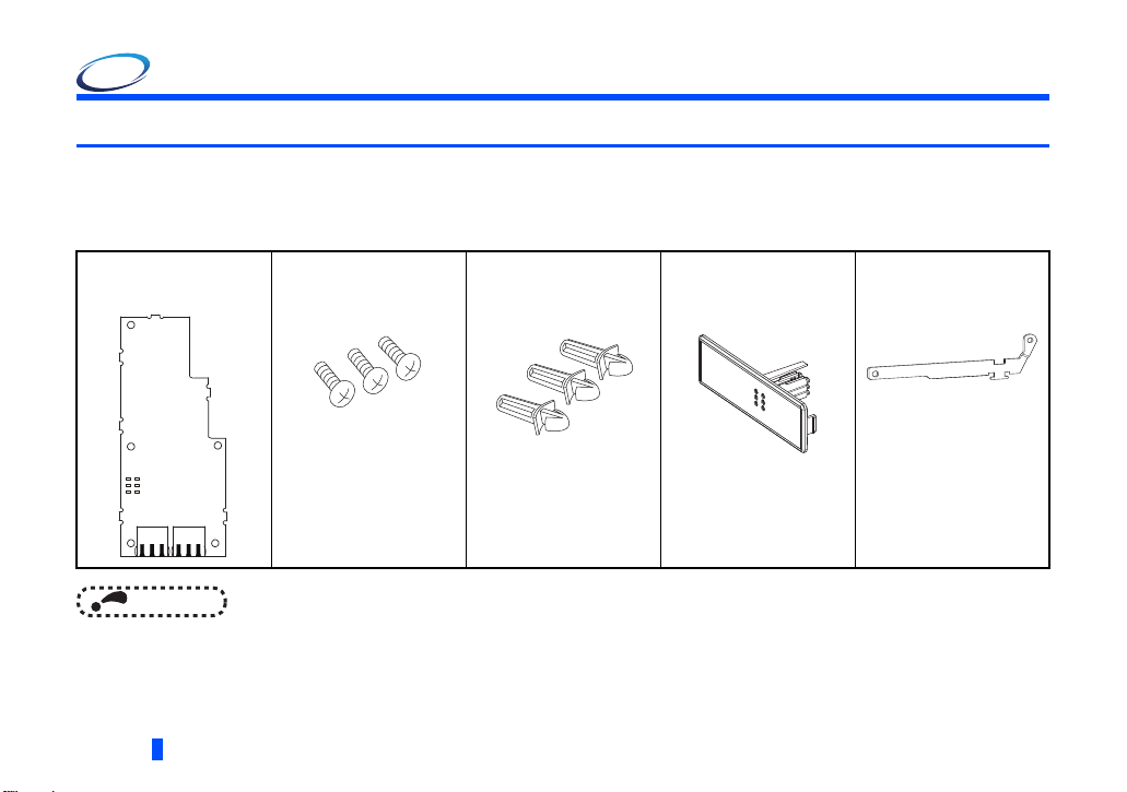
Product confirmation
Check the enclosed items.
Plug-in option
...................................... 1
RUN D LINK
SD ERR
RD L.ERR
NOTE
• ETHERNET is a registered trademark of Xerox Corporation in the United States.
Mounting screw
(M3 8 mm)
....... 3 (Refer to page 12.)
Spacer
....... 3 (Refer to page 12.)
Communication option
LED display cover
....... 1 (Refer to page 11.)
Earth plate
....... 1 (Refer to page 12.)
6
PRE-OPERATION INSTRUCTIONS
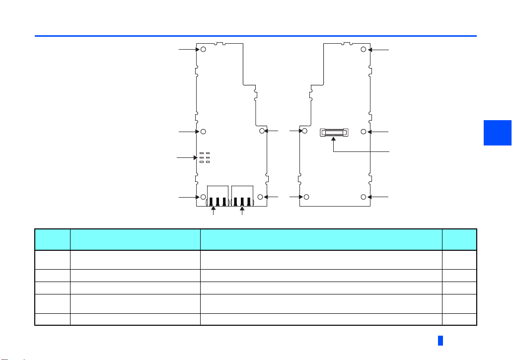
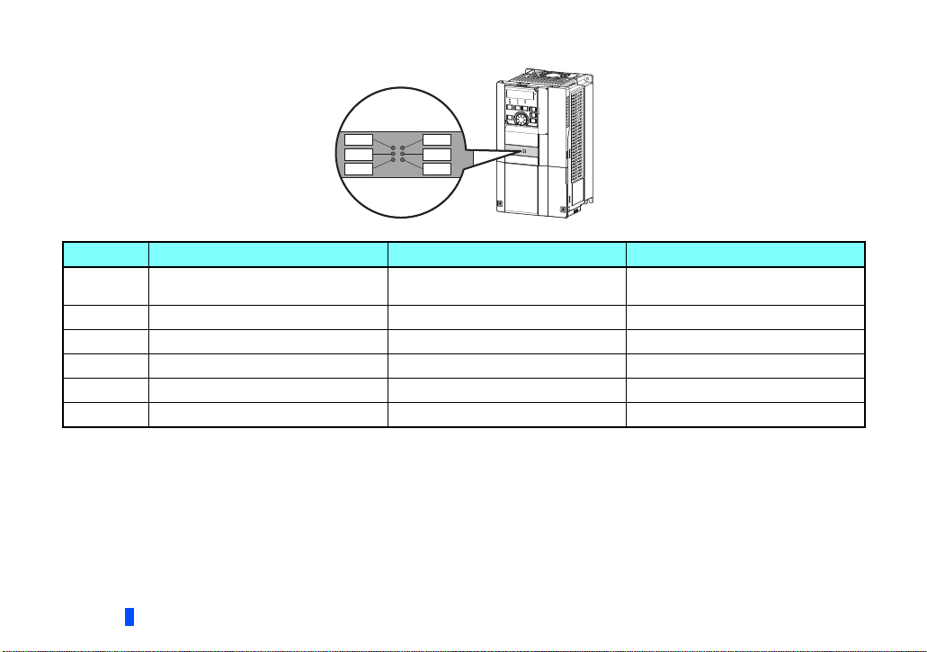
1.2 Parts
RUN D LINK
SD ERR
RD L.ERR
Front view
Rear view
(e)
(a)
(a)
(d)
(a)
(b)(c)
(a)
(a)
(a)
(a)
(a)
1
Symbol Name Description
a Mounting hole
b Connector for communication (PORT 1) For an Ethernet cable which connects to the network.
c Connector for communication (PORT 2) For an Ethernet cable which connects to the network.
d Operation status indication LED
e Board mounted option connector Used to connect this product to the option connector on the inverter. 12
Used to fix this product to the inverter by inserting a mounting screw or a
spacer.
Indicates operation/communication status of the inverter by turning ON or
blinking.
PRE-OPERATION INSTRUCTIONS
Refer
to page
12
18
18
8
7
Operation status LEDs
SD
ERR
L.ERRRD
D LINK
RUN
LED name Description ON OFF
RUN Operation status
SD Transmission status Data transmitting No data transmitting
RD Reception status Data receiving No data receiving
D LINK Cyclic communication status Cyclic transmitting No cyclic transmitting or disconnected
ERR Node failure status
Node failure Normal operation
L.ERR Link error Received data error Received data normal
Also lit in no-communication state.
This LED indicates a communication break between the master station and FR-A8NCE (due to cable disconnection or breakage, power-
OFF of the master power supply, or reset, etc.)
Normal operation (normal 5 V internal
voltage)
Hardware failure
8
PRE-OPERATION INSTRUCTIONS

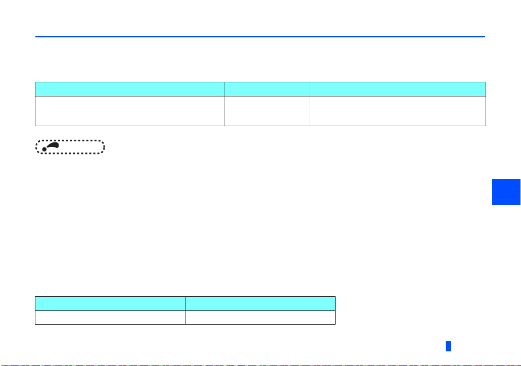
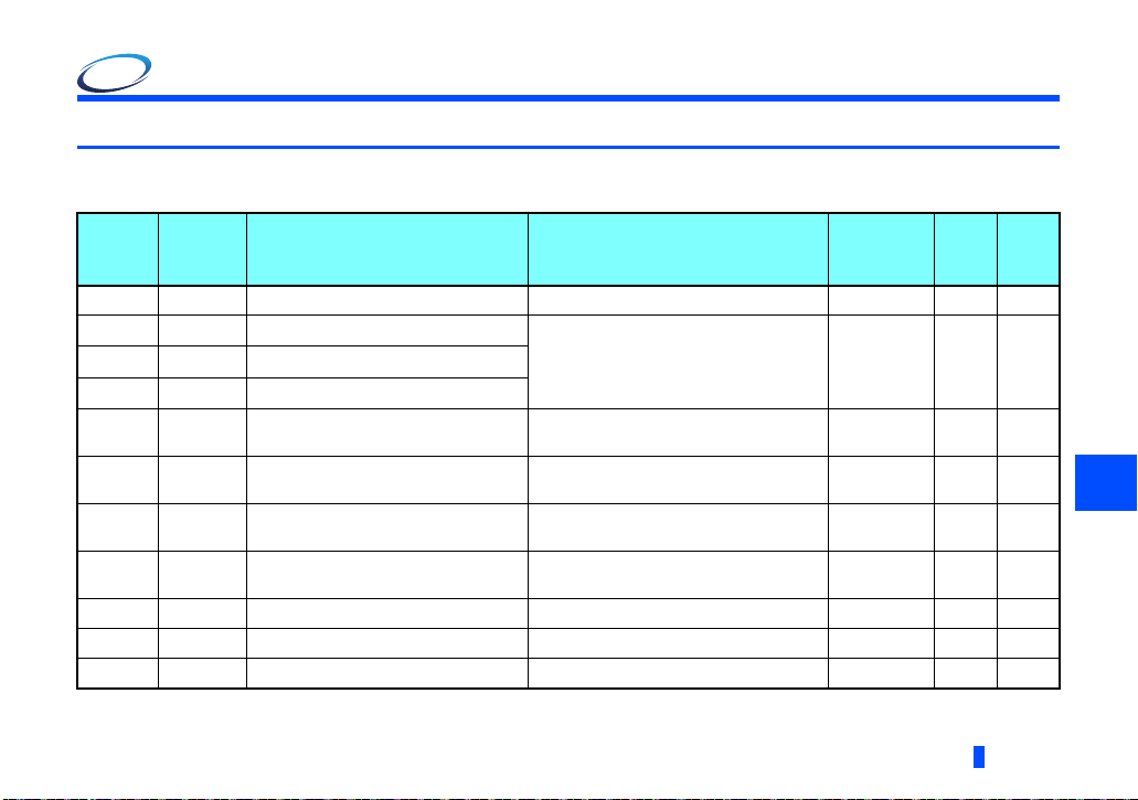
1.3 CC-Link IE Field Network communication specifications
Item Description
Type Inverter plug-in option type, RJ-45 connector connection method
Power supply Supplied from the inverter
Transmission speed 1 Gbps
Communication method Token passing
Number of units
connected
Maximum distance
between nodes
Maximum number of
branches
Topology Line, star, ring, or a combination of line and star
Connection cable
Connector Shielded RJ-45
Node type Intelligent device station Maximum cyclic size (of one node)
120 units max. (64 units when all stations are inverters handling 128-word transmissions.)
Different devices can be connected together.
100 m
No upper limit within the same Ethernet system
Ethernet cable
(IEEE 802.3 1000BASE-T compliant cable or ANSI/TIA/EIA-568-B (Category 5e) compliant shielded 4-pair
branched cable)
RX 64 bits
RY 64 bits
RWr 128 words
RWw 128 words
1
PRE-OPERATION INSTRUCTIONS
9
2 INSTALLATION
2.1 Pre-installation instructions
Check that the inverter's input power and the control circuit power are both OFF.
CAUTION
Do not install or remove this product while the inverter power is ON. Doing so may damage the inverter or this product.
To avoid damage due to static electricity, static electricity in your body must be discharged before you touch this product.
10
INSTALLATION
2.2 Installation procedure
Cut off the tabs with a nipper, etc.
Cut off the tabs with a nipper, etc.
Communication option LED display cover
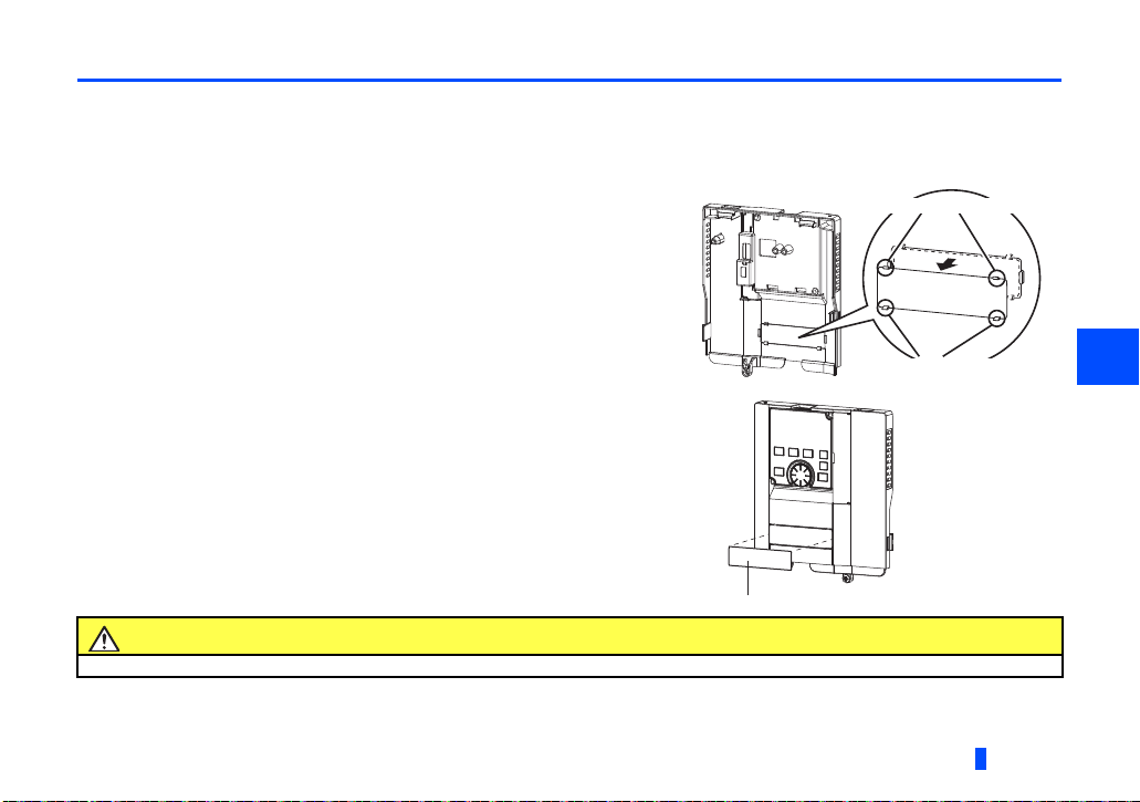
Installing the communication option LED display cover
(1) Remove the inverter front cover. (Refer to Chapter 2 of the Instruction Manual (Detailed) of the inverter for instructions for
removing the front cover.)
Follow instructions for mounting the communication option LED display cover to the inverter front cover.
(2) Cut off the tabs on the rear of the inverter front cover with nipper, etc. and
remove the separate part to make space for fitting the LED display cover.
(3) Fit the communication option LED display cover to the front side of the
front cover. Align the LED display cover with the LED position on the
circuit board of the option. Push the LED display cover until it is fixed with
the clips.
CAUTION
Take care not to hurt your hand and such with portions left by cutting tabs of the rear of the front cover.
2
INSTALLATION
11
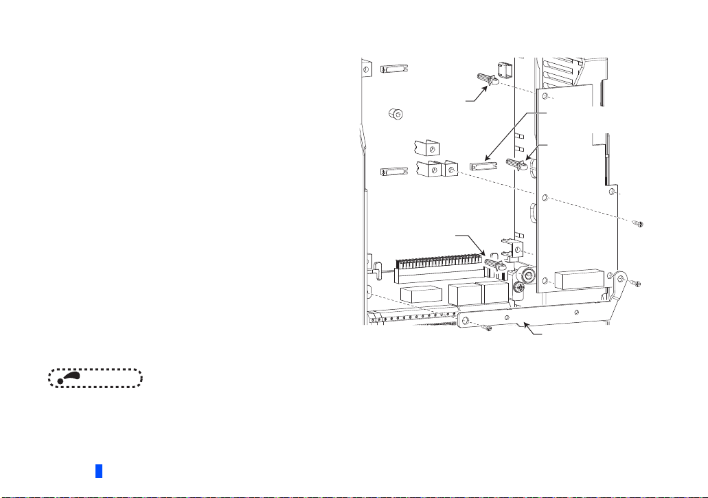
Installing the option
Spacer
Spacer
Spacer
Earth plate
Option connector
on the inverter
Installation to connector 1
(1) Insert three spacers into the mounting holes that will not
be filled with mounting screws (see the diagrams on the
next page to identify the holes).
(2) Fit the board mounted option connector on this product to
the guide of the option connector on the inverter and
insert the plug-in option as far as it goes. (Select option
connector 1 on the inverter.)
(3) Fasten the earth plate to the inverter using the one
mounting screw through the hole on the left side (see the
diagrams on the next page to identify the hole) (tightening
torque 0.33 N·m to 0.40 N·m).
(4) Fasten this product to the inverter using the one mounting
screw through the hole on the left side. Fasten the earth
plate and this product to the inverter using the last screw
through the hole on the right side of the earth plate and
this product (tightening torque 0.33 N·m to 0.40 N·m). If
the screw holes do not line up, the connector may not be
inserted deep enough. Check the connector.
NOTE
• When a communication option is installed to the FR-A800-E/FR-F800-E series inverter, use the earthing (grounding)
cable supplied with the inverter instead of the earth plate supplied with the communication option. (For details of the
installation method, refer to the Instruction Manual of the inverter.)
12
INSTALLATION
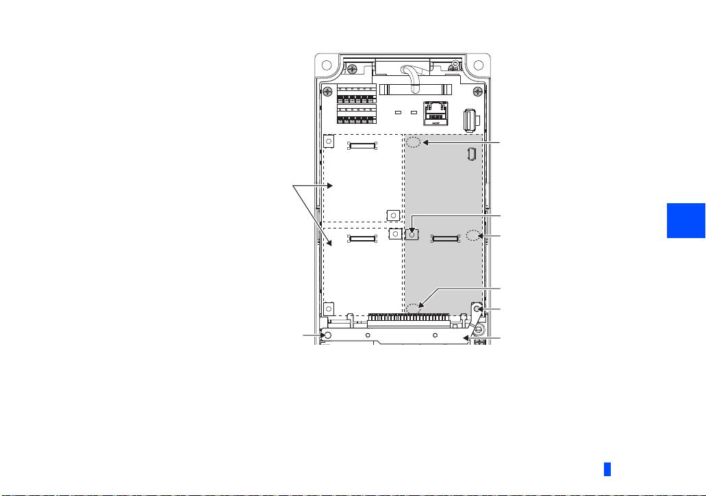
Spacer
Do not attach the plug-in option to connector 2 or 3.
Mounting screw
Connector 3
Mounting screw
Spacer
Connector 1Connector 2
Spacer
Mounting screw
Earth plate
Insertion positions for screws and spacers
INSTALLATION
2
13
NOTE
• When installing/removing the plug-in option, hold the sides of the option. Do not press on the parts on the option circuit
board. Stress applied to the parts by pressing, etc. may cause a failure.
• Be careful not to drop mounting screws during the installation or removal of the plug-in option.
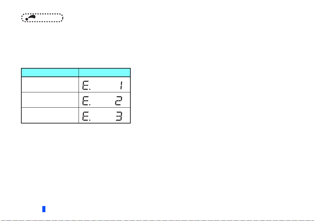
• Attach this product to option connector 1 on the inverter. If it is attached to option connector 2 or 3, the protective
function (E.2 or E.3) is activated and the inverter will not operate.
Even if this product is attached to option connector 1, when the inverter cannot recognize that the option is mounted
due to improper installation, etc., the protective function (E.1) is activated.
Mounted position Fault indication
Option connector 1
Option connector 2
Option connector 3
• When removing the plug-in option, remove the two screws on either side, then pull it straight out. Pressure applied to
the connector and to the option board may break the option.
• Always attach the earth plate because a malfunction due to noises may occur without it.
14
INSTALLATION
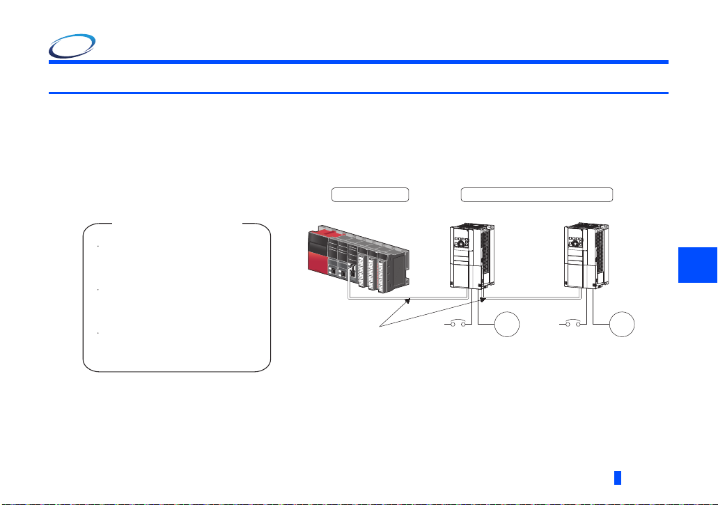
3 WIRING
Inverter
Motor
Power
supply
Inverter
Motor
Power
supply
Up to 120
units can be
connected
RJ71GF11-T2
Intelligent device station
RJ71EN71 type, RJ71GF11-T2 type
MELSEC iQ-R CC-Link IE Field Network
User's Manual (Application)
...............SH-081259ENG
LJ71GF11-T2 type
MELSEC-L CC-Link IE Field Network
Master/Local Module User's Manual
...............SH-080972ENG
Instruction manual regarding
the CC-Link IE Field Network
master station
Ethernet cable
QJ71GF11-T2 type
MELSEC-Q CC-Link IE Field Network
Master/Local Module User's Manual
...............SH-080917ENG
Master station
3.1 System configuration example
(1) Programmable controller side
Mount the "RJ71EN71", "RJ71GF11-T2", "QJ71GF11-T2", or "LJ71GF11-T2" type CC-Link IE Field Network master/local
module on the main or extension base unit having the programmable controller CPU used as the master station.
(2) Inverter side
Mount the option (FR-A8NCE) on the inverter.
(3) Connect the CC-Link IE Field Network programmable controller (master station) to FR-A8NCE with an Ethernet cable.
3
WIRING
15
3.2 Network configuration
Network topology
The network can be wired into star topology, line topology, and ring topology.
A network can consist of a combination of star and line topologies, but the ring topology cannot be combined with star or line
topology.
Item Description
Star topology
Line topology
Ring topology
Add/remove slave stations one by one. If multiple slave stations are added/removed at a time, all stations on the network will be
Station number and connection position
Modules can be connected in any order regardless of the station number.
Cascade connection
Up to 20-layer connection is available for the cascade connection.
Replacing CC-Link IE Field Network devices
For star topology, slave stations can be replaced without powering off the whole system.
NOTE
Modules are configured into a star using a switching hub and Ethernet cables. Slave stations can be easily added in a
star topology. Furthermore, data link continues among normally-operating stations in a star topology.
Modules are configured into a line with Ethernet cables and without a switching hub. If an error occurs, the station in
error and the stations after that will be disconnected from the network.
Modules are configured into a ring using Ethernet cables. Data link continues among normallyoperating stations without
a switching hub.
reconnected, resulting in a momentarily error in all the stations.
• Refer to the MELSEC iQ-R, MELSEC-Q, or MELSEC-L CC-Link IE Field Network Master/Local Module User's Manual
for the detailed network configurations.
16
WIRING
3.3 Network components
This section describes components comprising the CC-Link IE Field Network.
3.3.1 Connection cable
For wiring, use the 1000BASE-T compliant Ethernet cables.
Ethernet cable Connector Typ e
Category 5e or higher
(Double shielded/STP) Straight cable
NOTE
• For CC-Link IE Field Network wiring, use the recommended wiring components by CC-Link Partner Association.
• Cables for CC-Link IE Controller Network cannot be used for CC-Link IE Field Network.
• Some cable connector shapes are not compatible with FR-A8NCE.
3.3.2 Hubs
Use hubs that meet the conditions listed below:
• Compliance with the IEEE802.3 (1000BASE-T)
• Support of the auto MDI/MDI-X function
• Support of the auto-negotiation function
• Switching hub (layer 2 switch)
A repeater hub is not available.
Operation is not guaranteed if the hubs do not meet these conditions.
Industrial switching hub
Typ e Manufacturer
NZ2EHG-T8 Mitsubishi Electric Corporation
RJ-45 connector
The following conditioning cables:
• IEEE802.3 (1000BASE-T)
• ANSI/TIA/EIA-568-B (Category 5e)
3
WIRING
17
3.4 Wiring
This section describes the cable wiring and precautions. For network configuration, cables, and hubs used for the wiring, refer
to page 16 and subsequent pages.
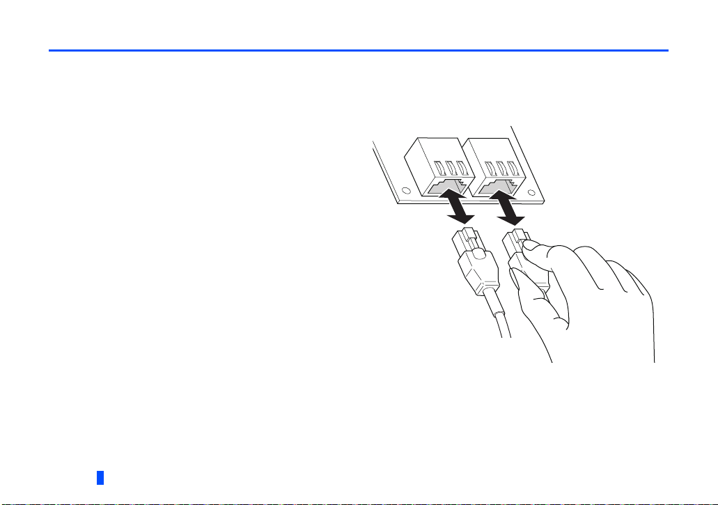
3.4.1 Ethernet cable connection
Connecting the cable
(1) Turn OFF the inverter power supply.
(2) Remove the front cover.
(3) Check the direction of the Ethernet cable connector.
Insert the connector to the communication connector of
FR-A8NCE until it clicks.
Disconnecting the cable
(1) Turn OFF the inverter power supply.
(2) Remove the front cover.
(3) Hold down the latch on the Ethernet cable connector, and
pull out the cable while holding the latch.
18
WIRING
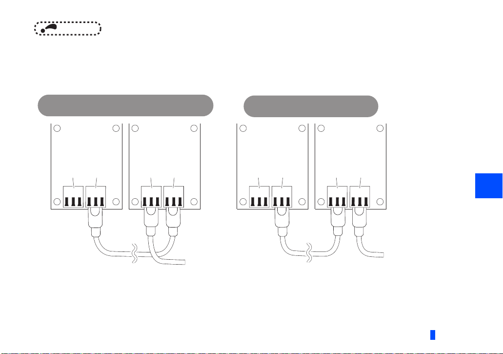
NOTE
• PORT1 and PORT2 do not need to be distinguished.
• When only one connector is used in star topology, either PORT1 or PORT2 is applicable.
• When using two connectors for line topology and ring topology, an Ethernet cable can be connected to the
connectors in any combination. For example, the cable can be connected between PORT1s or between PORT1
and PORT2.
Connection between
PORT1 and PORT1, PORT2 and PORT2
Connector
for
communication
(PORT2)
Connector
for
communication
(PORT1)
Connector
communication
(PORT2)
for
Connector
for
communication
(PORT1)
To the next
connector for
communication
(PORT2)
Connector
for
communication
(PORT2)
Connection between
PORT1 and PORT2
Connector
for
communication
(PORT1)
Connector
communication
(PORT2)
for
Connector
for
communication
(PORT1)
To the next
connector for
communication
(PORT2)
WIRING
3
19

3.4.2 Precautions
This section describes wiring precautions.
Handling of the Ethernet cable
• Do not touch the core of the cable-side or module-side connector, and protect it from dirt or dust. If oil from your hand, dirt or
dust is attached to the core, it can increase transmission loss, arising a problem in data link.
• Check the following:
• Is any Ethernet cable disconnected?
• Is any of the Ethernet cables shorted?
• Are the connectors securely connected?
Broken Ethernet cable latch
Do not use Ethernet cables with broken latches. Doing so may cause the cable to unplug or malfunction.
Connecting and disconnecting the Ethernet cable
Hold the connector part when connecting and disconnecting the Ethernet cable. Pulling a cable connected to the module may
damage the module or cable, or result in malfunction due to poor contact.
Maximum station-to-station distance (maximum cable length)
The maximum station-to-station distance is 100 m. However, the distance may be shorter depending on the operating
environment of the cable. For details, contact your cable manufacturer.
Network configuration
Check the instructions on page 16 before wiring, and perform correct wiring.
20
WIRING
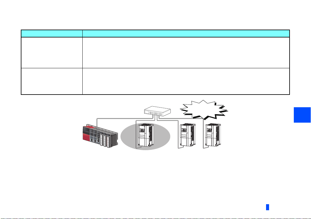
Connecting/disconnecting a cable and powering ON/OFF a device
When the operations listed below are performed, all stations on the network may be reconnected. At that time, a data link error
may momentarily occur in all the stations, and the communication error E.OP1 may occur in the connected inverters.
Network configuration Operation
• Powering ON/OFF a slave station or the switching hub
• Connecting/disconnecting an Ethernet cable connected to the switching hub
Star topology
Line topology,
ring topology
• Disconnecting an Ethernet cable from a slave station and connecting it to another slave station or to the
switching hub
• Disconnecting ten stations or more, or disconnecting half the number of slave stations in the system or more
• Changing the network topology when adding a slave station
• Simultaneously powering ON/OFF multiple stations
• Simultaneously connecting/disconnecting Ethernet cables to/from multiple stations
(When a data link faulty station returns, a data link error will occur in all the stations.)
• Disconnecting ten stations or more, or disconnecting half the number of slave stations in the system or more
• Changing the network topology when adding a slave station
A momentary error
in all stations
At plug in/unplug or power ON/OFF
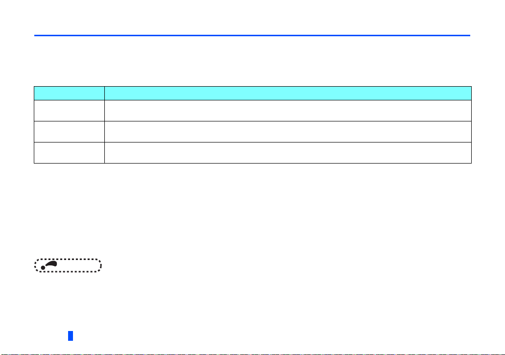
To keep outputting a data link error (inverter communication error), set Pr.500 Communication error execution waiting time
or Pr.502 Stop mode selection at communication error
3
WIRING
21

NOTE
• When wiring cables to the inverter's RS-485 terminals with a plug-in option mounted, take caution not to let the cables
.
touch the circuit board of the option or of the inverter. Otherwise, electromagnetic noises may cause malfunctions.
Caution
After wiring, wire offcuts must not be left in the inverter. Wire offcuts can cause an alarm, failure or malfunction.
22
WIRING
4 INVERTER SETTING
4.1 Parameter list
The following parameters are used for the plug-in option (FR-A8NCE). Set the values according to need. For the parameter
details, which depend on the applicable model of the inverter, refer to the Instruction Manual (Detailed) of the inverter.
Pr.
79 D000 Operation mode selection 0 to 4, 6, 7 1 0 25
313
M410 DO0 output selection
M411 DO1 output selection
M412 DO2 output selection
315
338 D010
339 D011
340 D001
342 N001
349 N010 Communication reset selection 0, 1 1 0 34
, N110, Network number (CC-Link IE) 0 to 255 1 0 36
434
, N111, Station number (CC-Link IE) 0 to 255 1 0 36
435
Pr.
group
Name Setting range
Communication operation command
source
Communication speed command
source
Communication startup mode
selection
Communication EEPROM write
selection
The setting range depends on the
inverter.
0, 1 1 0
0 to 2 1 0
0 to 2, 10, 12 1 0 25
0, 1 1 0
Minimum
setting
increments
1 9999 56314
Initial
value
INVERTER SETTING
Refer
to
page
4
23

Pr.
500 N011
N012
501
502 N013
541
N100 Frequency command sign selection 0, 1 1 0 37
550
D012
779 N014
804
D400 Torque command source selection 0, 1, 3 to 6 1 0 68
H700 Torque limit input method selection 0 to 2 1068
810
Pr.
group
Communication error execution
waiting time
Communication error occurrence
count display
Stop mode selection at communication
error
NET mode operation command source
selection
Operation frequency during
communication error
Parameters which can be displayed when the plug-in option (FR-A8NCE) is installed.
The setting is reflected after inverter reset or at the next power-ON.
Refer to the Instruction Manual (Detailed) of the inverter for the parameter details.
The setting is available only for the FR-A800 series.
This setting of Pr.810="2" can be set only when the inverter supports this function. (Refer to page 68.)
Name Setting range
0 to 999.8 s 0.1 s 0 s 28
01029
0 to 4, 11, 12 1 0 29
0, 1, 9999 1 9999
0 to 590 Hz, 9999 0.01 Hz 9999 29
Minimum
setting
increments
Initial
value
Refer
to
page
24
INVERTER SETTING

4.2 Operation mode setting
4.2.1 Operation mode switching and communication startup mode (Pr.79, Pr.340)
Operation mode switching conditions
Check the following before switching the operation mode.
• The inverter is at a stop;
• Both the STF and STR signals are off; and
• The Pr.79 Operation mode selection setting is correct.
(Check the setting on the operation panel of the inverter.)
Operation mode selection at power ON and at restoration from instantaneous power failure
The operation mode at power ON and at restoration from instantaneous power failure can be selected.
Set a value other than "0" in Pr.340 Communication startup mode selection to select the network operation mode.
After started in network operation mode, parameter write from the network is enabled.
(Refer to page 80 for a program example for parameter write.)
NOTE
• Change of the Pr.340 setting is valid when powering on or resetting the inverter.
• Pr.340 can be changed with the operation panel independently of the operation mode.
• Ensure that the communication setting of the inverter is completed before setting Pr.340 "0".
• Refer to the Instruction Manual (Detailed) of the inverter for details of Pr.79, Pr.340.
4
INVERTER SETTING
25
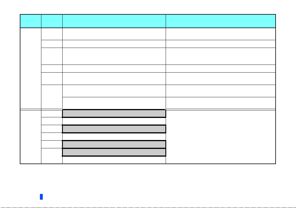
Pr.340
setting
0
(initial
value)
1, 2
Pr.79
setting
0 (initial
value)
1 PU operation mode PU operation mode fixed
2 External operation mode
3, 4 External/PU combined operation mode Operation mode switching is disallowed.
6 External operation mode
7
0 NET operation mode
1 PU operation mode
2
3, 4 External/PU combined operation mode
6
7
Operation mode at power ON or power
restoration
External operation mode
X12 (MRS) signal ON: external operation mode
X12 (MRS) signal OFF: external operation mode
NET operation mode
NET operation mode
X12 (MRS) signal ON........ NET operation mode
X12 (MRS) signal OFF........external operation mode
Operation mode switchover
Switching among the External, PU, and NET operation
mode is enabled.
Switching between the External and Net operation mode is
enabled.
Switching to the PU operation mode is disallowed.
Switching among the External, PU, and NET operation
mode is enabled while running.
Switching among the External, PU, and NET operation
mode is enabled.
External operation mode fixed (Forcibly switched to
External operation mode.)
Same as when Pr.340 = "0"
,
,
26
INVERTER SETTING
 Loading...